spatial modulation in the underwater acoustic channel ... · pdf filespatial modulation in the...
TRANSCRIPT

Spatial Modulation in the Underwater Acoustic Channel
Daniel KilfoyleSAIC
phone: 508-274-1197email: [email protected]
Abstract Multiple-input multiple-output (MIMO) communication channels are anactive area of research for terrestrial wireless applications. The natural bandwidthlimitations of the underwater acoustic channel (UAC) combined with the potentialfor a rich spatial propagation structure suggest the ocean may be another usefulapplication area for MIMO techniques.
An underwater acoustic communications experiment was conducted in the waterssurrounding Elba, Italy, using spatially modulated signals. Two frequency regimes(9.5-14.5 kHz and 25-35 kHz) were explored over ranges up to 5 km usingvertical line arrays suspended from drifting ships. The UAC had an averagedepth of 100 m. One-way communication links were established at two siteswith one site having a rocky (reverberant) bottom and the other having a muddy(absorbent) bottom.
The waveform comprised a single data stream with concatenated codes providingerror control. The inner code was a high rate BCH code. Trellis-coded modulationwas used as the basis for the outer code. Successive coded symbols weremultiplexed across the available transducer elements. This coding approacheffectively maintains the inherent bandwidth efficiency of MIMO signaling.
The receiver was an adaptive recursively updated multichannel decision feedbackequalizer operating in conjunction with a digital phase-locked loop. A packet-based, transport architecture was used and included a training sequence. AViterbi algorithm was integrated with the equalizer that supported simultaneoustap-weight update and trellis transversal, thereby affording the decision-directedupdate partial error control.
Using appropriate assumptions, channel capacity using a single transducerwas estimated to be 5.4 bits/channel use at the soft bottom site. Capacity wasmaximized at 15.9 bits/channel use using four transducers. More detailed resultswill be presented along with performance predictions based on both propagationmodels and measured channel transfer functions.

Form ApprovedReport Documentation Page OMB No. 0704-0188
Public reporting burden for the collection of information is estimated to average 1 hour per response, including the time for reviewing instructions, searching existing data sources, gathering andmaintaining the data needed, and completing and reviewing the collection of information. Send comments regarding this burden estimate or any other aspect of this collection of information,including suggestions for reducing this burden, to Washington Headquarters Services, Directorate for Information Operations and Reports, 1215 Jefferson Davis Highway, Suite 1204, ArlingtonVA 22202-4302. Respondents should be aware that notwithstanding any other provision of law, no person shall be subject to a penalty for failing to comply with a collection of information if itdoes not display a currently valid OMB control number.
1. REPORT DATE 2. REPORT TYPE 3. DATES COVERED
20 DEC 2004 N/A
4. TITLE AND SUBTITLE 5a. CONTRACT NUMBER
Spatial Modulation in the Underwater Acoustic Channel 5b. GRANT NUMBER
5c. PROGRAM ELEMENT NUMBER
6. AUTHOR(S) 5d. PROJECT NUMBER
5e. TASK NUMBER
5f. WORK UNIT NUMBER
7. PERFORMING ORGANIZATION NAME(S) AND ADDRESS(ES) 8. PERFORMING ORGANIZATION
SAIC REPORT NUMBER
9. SPONSORING/MONITORING AGENCY NAME(S) AND ADDRESS(ES) 10. SPONSOR/MONITOR'S ACRONYM(S)
11. SPONSOR/MONITOR'S REPORT
NUMBER(S)
12. DISTRIBUTION/AVAILABILITY STATEMENT
Approved for public release, distribution unlimited
13. SUPPLEMENTARY NOTES
See also, ADMOO1741 Proceedings of the Twelfth Annual Adaptive Sensor Array Processing Workshop,16-18 March 2004 (ASAP-12, Volume 1)., The original document contains color images.
14. ABSTRACT
15. SUBJECT TERMS
16. SECURITY CLASSIFICATION OF: 17. LIMITATION OF 18. NUMBER 19a. NAME OF
ABSTRACT OF PAGES RESPONSIBLE PERSON
a. REPORT b. ABSTRACT c. THIS PAGE UU 20unclassified unclassified unclassified
Standard Form 298 (Rev. 8-98)Pirscribed by ANSI Std Z39-18

SPATIAL MODULATION IN THE UNDERWATER ACOUSTIC CHANNELDaniel Kilfoyle, Science Applications International Corporation
406 Sippewissett Road, Falmouth, MA 02540 [email protected] Freitag, Woods Hole Oceanographic Institution
operating a PCS-band phone can expect coherence times ofABSTRACT nearly 10000/B. These conditions demand sophisticated
Multiple-input / multiple-output (MIMO) equalizer structures with rapid adaptation rates. Algorithmscommunication channels are an active area of research for developed by the underwater acoustic telemetry communityterrestrial wireless applications. The natural bandwidth may prove valuable when terrestrial wireless MIMO systemslimitations of the underwater acoustic channel (UAC) combined inevitably migrate to ultra-high bandwidth, mobile applications.with the potential for a rich spatial propagation structure In this paper, the relatively mature equalizer structuresuggests the ocean is another useful application area for MIMO developed for the UAC is extended to support MIMO signalingtechniques. An underwater acoustic communications and validated in sea trials. In section I, the baseline algorithm isexperiment was conducted in the waters surrounding Elba, described. The motivation for a particular error coding strategyItaly, using spatially modulated signals. Two frequency is presented. In section III, details of the at-sea testingregimes (9.5 - 14.5 kHz and 25 - 35 kHz) were explored over procedure used near Elba, Italy, during October 2003, are given.ranges up to 5 km using vertical line arrays. One-way Section IV reviews the estimated channel capacity increasescommunication links were established at two sites with one site provided by the use of spatial modulation, showing itshaving a rocky (reverberant) bottom and the other having a effectiveness, while pointing out the limitations imposed bymuddy (absorbent) bottom. The waveform comprised a single channel dispersion. The final section will summarize the keydata stream with concatenated codes providing error control. ideas addressed in this paper.The receiver was an adaptive recursively updated multi-channeldecision feedback equalizer operating in conjunction with a II. EQUALIZER DESIGNdigital phase locked loop. Channel capacity using a singletransducer was estimated to be 7.6 bits/channel use at the soft For the purpose of receiver design, communication via spatialbottom site. Capacity was maximized at 23.0 bits/channel use modulation is a form of multi-user communication where thereusing four transducers at that site. While the receiver was is the possibility of introducing dependency between differenteffective, the ability of the equalizer to cope with channel users. Rather than relying on frequency division multipledispersion effects was a limiting factor. access (FDMA) or code division multiple access (CDMA)
techniques, the spatial modulation receiver separates signals byI. INTRODUCTION using the differing spatial signatures of the data streams to
separate them. The demodulation algorithm used in theseUnderwater acoustic communication provides a experiments is based on the multi-user receiver structure
unique capability that is important to many users in both described by Stojanovic and Zvonar [4]. A number of similargovernment and private industry. At the same time, the and competing equalizer structures are described in thedynamic and dispersive nature of the underwater acoustic literature [5].channel (UAC) has limited demonstrated data rates to well Referring to figure 1, the first step is a coarse timingbelow those common to other systems such as landline and and carrier synchronization typically done via correlating with awireless [1], particularly for horizontal propagation paths. With training sequence appended to each packet of symbols. Thefundamental limits on bandwidth, mostly dictated by the equalization and channel separation task is accomplished withattenuation characteristics of sea water [2], increasing spectral the joint application of tapped delay lines on each receivedefficiency, defined as the ratio of data rate to signal bandwidth, signal, decision feedback filters for all data streams, and ais an important approach to increasing data rates. The digital phase locked loop. Decisions are based on a minimumsuccessful demonstration of phase coherent signaling [3] was a Euclidian distance metric that compares the symbol estimatemilestone in the field as it enabled bandwidth efficiencies of vector to a map of valid messages. The decisions are made withtwo or more over practical long-range horizontal a Viterbi algorithm that operates in concert with the equalizercommunication paths. The exploitation of the ocean's rich on a symbol-to-symbol basis. Soft decisions with low latencyspatial structure through the use of spatial modulation can (typically less than 10 symbols) are released to support the filterprovide significant additional bandwidth efficiency gains. update while hard decisions are released with a higher latency.
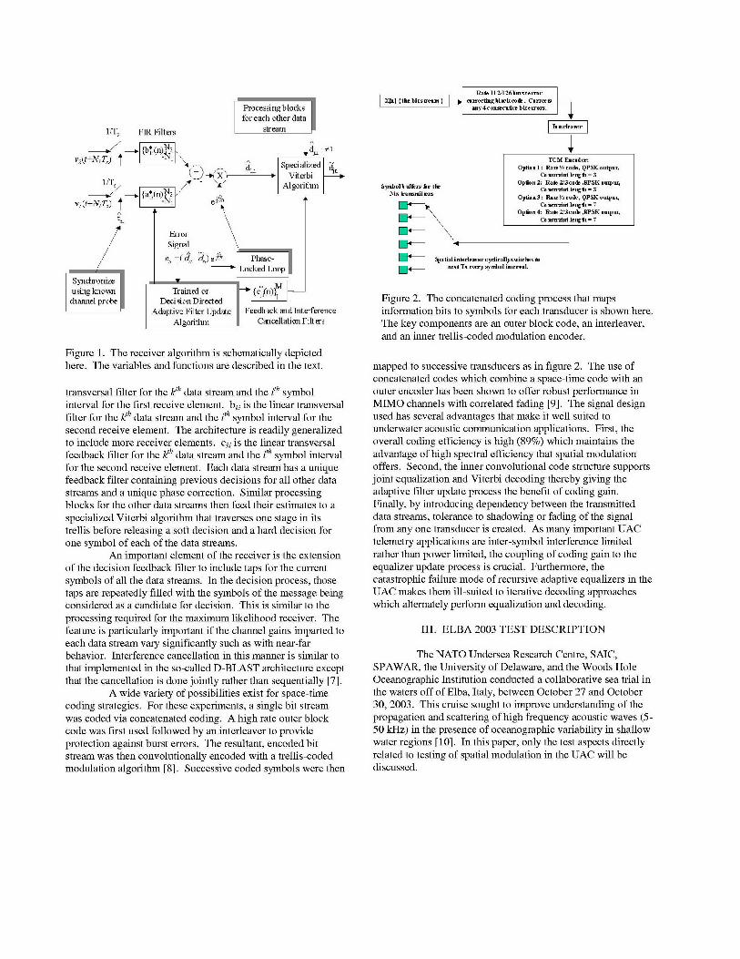
The UAC exhibits stressing traits that have yet to The general area of delayed decision feedback sequencesurface, for the most part, in terrestrial wireless MIMO estimation is addressed by Duel-Hallen [6].channels. Temporal dispersion due to the waveguide nature of The essential difference between this receiver and athe UAC leads to impulse responses that often extend from typical multi-user decision feedback equalizer is the integration10/B to 100/B in duration, where B is the signal bandwidth. In of the Viterbi algorithm with the adaptation process and thecontrast, urban spread spectrum systems such as those inclusion of feedback filtering within the Viterbi trellis. Noteconforming to the IS-95B and 1XRTT standards rarely see that the diagram shown in figure 4 is only intended to show thesignificant multipath extents beyond 10/B. Frequency processing for one data stream. More specifically, vi is thedispersion due to sea surface motion, platform movement, and received data for the th receiver element. T, is the symboleven seawater currents and turbulence often lead to coherence interval. N1 and N2 are the durations, before and after thetimes of 100/B. In contrast, a vehicle traveling 30 m/s while timing reference, that have delay tap support. aki is the linear
SRate l11Z126bu..teor
Procesing blocks [ly4conseeutiee bitteron.7
for each other data
l/T1 FIR Filters stream
V2Qt+N1TJ) pt.ý I~ PK
d Speci alized a/,d, tu,VOption: Rae½code, QPb, outpuo,
lIT Algorithm Syrb ol h vmf rn the Opttmn2: Rate 2(3cod PSK ouoput,
v1(t+NT) T - et-otnio _b-ldt ,•o•,P o7"" - Opttmn4: Rate 23 tco So,8PSK output,
FrTorSignal
e (4 d,)eJn' Phase- Spafatiadinterler.ydicaylly-sit•rs to
Locked Loop _-_ next Tx everysyoyolbntervalSyn chro nize, F{•Flee
using knowns |Trained orchannel probe D iFigure 2. The concatenated coding process that maps
Adaptive Filter Update Feedback and Interference information bits to symbols for each transducer is shown here.Algorithm Cancellation Filters The key components are an outer block code, an interleaver,
and an inner trellis-coded modulation encoder.
Figure 1. The receiver algorithm is schematically depictedhere. The variables and functions are described in the text. mapped to successive transducers as in figure 2. The use of
concatenated codes which combine a space-time code with antransversal filter for the kt1h data stream and the ith symbol outer encoder has been shown to offer robust performance ininterval for the first receive element. bki is the linear transversal MIMO channels with correlated fading [9]. The signal designfilter for the kth data stream and the ith symbol interval for the used has several advantages that make it well suited tosecond receive element. The architecture is readily generalized underwater acoustic communication applications. First, theto include more receiver elements. cki is the linear transversal overall coding efficiency is high (89%) which maintains thefeedback filter for the kth data stream and the ith symbol interval advantage of high spectral efficiency that spatial modulationfor the second receive element. Each data stream has a unique offers. Second, the inner convolutional code structure supportsfeedback filter containing previous decisions for all other data joint equalization and Viterbi decoding thereby giving thestreams and a unique phase correction. Similar processing adaptive filter update process the benefit of coding gain.blocks for the other data streams then feed their estimates to a Finally, by introducing dependency between the transmittedspecialized Viterbi algorithm that traverses one stage in its data streams, tolerance to shadowing or fading of the signaltrellis before releasing a soft decision and a hard decision for from any one transducer is created. As many important UACone symbol of each of the data streams. telemetry applications are inter-symbol interference limited
An important element of the receiver is the extension rather than power limited, the coupling of coding gain to theof the decision feedback filter to include taps for the current equalizer update process is crucial. Furthermore, thesymbols of all the data streams. In the decision process, those catastrophic failure mode of recursive adaptive equalizers in thetaps are repeatedly filled with the symbols of the message being UAC makes them ill-suited to iterative decoding approachesconsidered as a candidate for decision. This is similar to the which alternately perform equalization and decoding.processing required for the maximum likelihood receiver. Thefeature is particularly important if the channel gains imparted to III. ELBA 2003 TEST DESCRIPTIONeach data stream vary significantly such as with near-farbehavior. Interference cancellation in this manner is similar to The NATO Undersea Research Centre, SAIC,that implemented in the so-called D-BLAST architecture except SPAWAR, the University of Delaware, and the Woods Holethat the cancellation is done jointly rather than sequentially [7]. Oceanographic Institution conducted a collaborative sea trial in
A wide variety of possibilities exist for space-time the waters off of Elba, Italy, between October 27 and Octobercoding strategies. For these experiments, a single bit stream 30, 2003. This cruise sought to improve understanding of thewas coded via concatenated coding. A high rate outer block propagation and scattering of high frequency acoustic waves (5-code was first used followed by an interleaver to provide 50 kHz) in the presence of oceanographic variability in shallowprotection against burst errors. The resultant, encoded bit water regions [10]. In this paper, only the test aspects directlystream was then convolutionally encoded with a trellis-coded related to testing of spatial modulation in the UAC will bemodulation algorithm [8]. Successive coded symbols were then discussed.

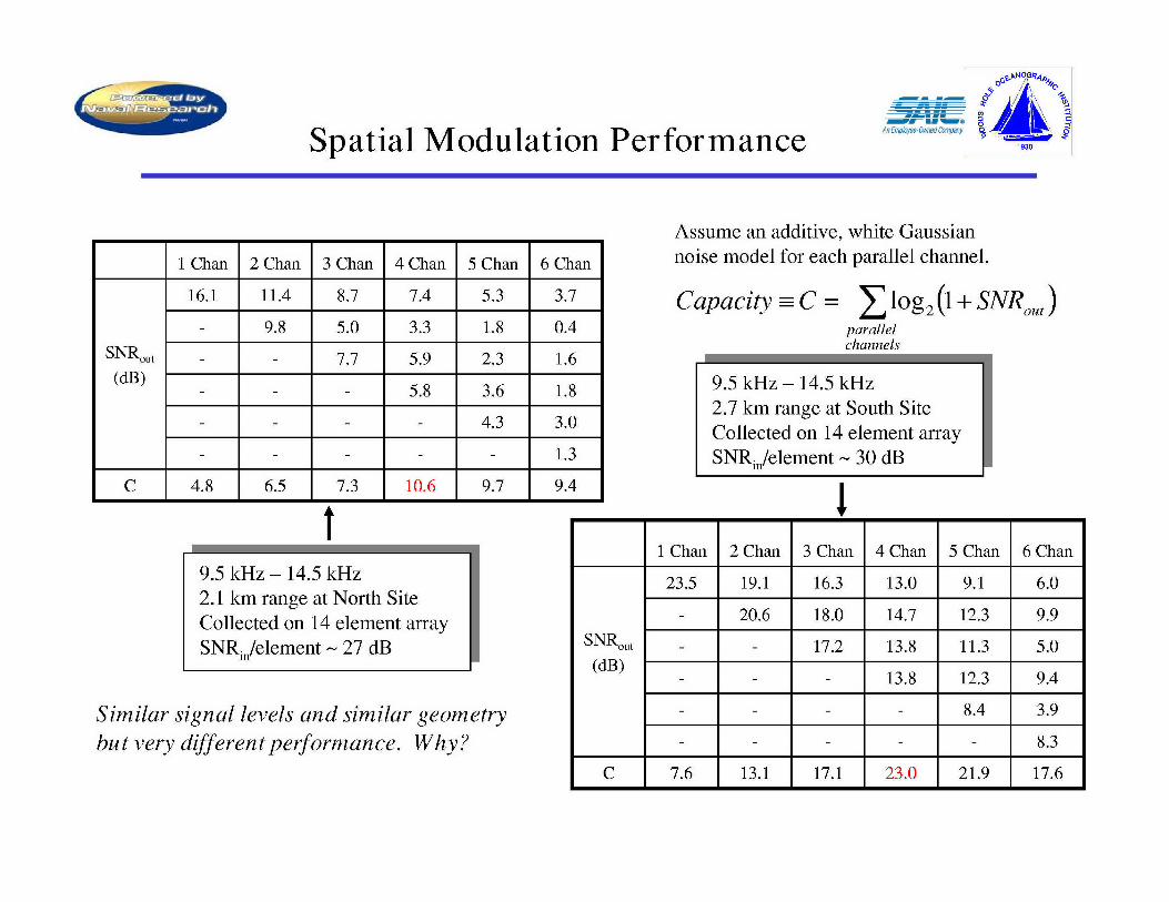
SNorth - Table 1. Post-equalization SNR for various levels of spatial'..... South modulation is shown here for the low frequency band at a range of
20- 2.1 km at the North site. C has units of bits/channel use.
"0 1 Chan 2 Chan 3 Chan 4 Chan 5 Chan 6 Chan40
16.1 11.4 8.7 7.4 5.3 3.7S SNRot
S60 (dB) 9.8 5.0 3.3 1.8 0.4
S7.7 5.9 2.3 1.6
80 5.8 3.6 1.8
4.3 3.0
100 1.3
C 4.8 6.5 7.3 10.6 9.7 9120
1500 1510 1520 1530Sound Speed (m/s) Table 2. Post-equalization SNR for various levels of spatial
modulation is shown here for the low frequency band at a range of2.5 km at the South site. C has units of bits/channel use.
Figure 3. The sound speed profiles at both siteswere downward refracting with a weak surfaceduct. The north site bottom layer transition was I Chan 2 Chan 3 Chan 4 Chan 5 Chan 6 Chan
quite abrupt. 23.5 19.1 16.3 13.0 9.1 6.0
SNRou_(dB) - 20.6 18.0 14.7 12.3 9.9
17.2 13.8 11.3 5.0
- 13.8 12.3 9.4
8.4 3.9
8.3
C 7.6 13.1 17.1 23.0 21.9 17.6
The test assets included the R/V Alliance, which but had substantial sediment deposits leading to severe bottomhosted a 14-element flexible hydrophone vertical line array attenuation. Typical sound velocity profiles from each site are(VLA) with 1 m spacing and a 12 element rigid hydrophone seen in figure 3. Each site exhibited a warm surface layer atopVLA with a 15 cm spacing. Each hydrophone array was a cooler bottom layer with an exceptionally steep gradient at thesufficiently wideband to record all signals transmitted. Two north site between the layers.transducer arrays were hosted by the vessel Saralu including a 6element, 2 m spaced, array tuned for operation between 9.5 and IV. RESULTS14 kHz and a 3 element, 53 cm spaced, transducer array tunedfor operation between 25 and 35 kHz. Packet-based waveforms In general, spatial modulation was more effective atwere alternately transmitted in both frequency bands. An the South site than at the North site. The effectiveness of theaverage power constraint was imposed. Testing parameters proposed receiver for each site will first be described. Theincluded the number of simultaneous, unique spatially observed differences will then be discussed in terms of themultiplexed packets (1 to 6 at the mid-band and 1 to 3 at the propagation conditions, namely time and frequency dispersion.high band) and symbol constellation size (4, 8, and 16-level A useful metric to characterize potentialquadrature amplitude modulation). communication performance is the post-equalization signal-to-
The two test sites were utilized specifically to provide noise ratio (SNR0 _t) of the data prior to the decision device. Bycontrasting environments that would aid understanding how processing the packet continually in training mode, systempropagation physics and communication performance are performance can be extrapolated from SNROUt to arbitraryrelated. The site to the North of Elba had a nominal water coding strategies. With appropriate assumptions, one may evencolumn depth of 100 m with hard, reverberant bottom structure. estimate the capacity given SNROt. Assuming that theThe site to the South of Elba also had a nominal depth of 100 m equalizer both whitens the residual noise and any channel-

14 1 1Tables 1 and 2 provide these metrics for a group of mid-
12 frequency band transmissions at the North and South site
S10 10.8 1*.8 respectively. While the North site showed approximately a8 two-fold increase in capacity through the use of four
0.performance with over a three-fold increase in capacity. The0 1EMI I O II 6 transducers, the South site yield superior spatial modulation
2 0 two sites were explicitly chosen to provide a contrast in2 4 6 8 10 12 14 2 4 6 8 10 12 14 telemetry performance. This result, however, was counter to
Element # Element # expectations prior to the test. With a hard bottom, the spatial
structure of the acoustic field at the North site was thought toprovide more potentially resolvable propagation paths while the
Figure 4. The array spatial covariance matrix for the soft bottom of the South site would deplete energy in ray pathslow-band transmissions at the North site (left panel) other than the direct arrival. These results show the opposite toand the South site (right panel) are shown. be true. This result suggests unexpected aspects of the acoustic
propagation are deeply affecting spatial modulation1 performance.
2- A classical analysis for predicting performance in aMIMO channel would examine the value and distribution of the
4- channel transfer function matrix singular values. For the testsconsidered in tables 1 and table 2, the average SNR per receiverelement was nearly equivalent at 24 dB and 22 dB respectively.
6 For the North site, the first four squared singular values are 20.5SdB, 17.5 dB, 14.7 dB, and 12.0 dB. For the South site, the first
S8 four values are 18.8 dB, 14.0 dB, 11.2 dB, and 6.0 dB. Theclassical conclusion would be that the North site is a better
10 candidate for spatial modulation as it has a higher overall SNRand a more favorable singular value distribution. In fact, the
12 ]opposite was found to be true. Two possible explanations will12 ..be considered.
10 20 30 40 50 Coherent UAC telemetry performance is often limitedDelay (msec) by residual inter-symbol interference (ISI). ISI typically results
from an inability of the equalizer to estimate and compensatefor channel dispersion. This may occur when the channel
4- coherence time is less than the averaging time required to
support reliable estimation. Spatial modulation is particularlyI6 sensitive to spatial coherence between the array elements.
SFigure 4 shows the array covariance matrix averaged over a 20S8- msec period for the low band transmission at both the North and
SI South sites. As can be seen, the North site had markedly less0I, coherence between the elements. The low-band array spacing
(8 wavelengths) was chosen to increase the resolving power. Inthe light of these results, it is clear that care must be taken to
12 Ibalance the requirement for resolution with the need forcoherence in designing appropriate arrays for spatial
14 modulation. In the presence of frequency dispersion,
0 5 10 15 20 25 30 35 optimization of array topology must account for coherence. ForDelay (msec) spatial modulation, the need for both receiver arrays and
adequate time taps to cover late, spatially distinct arrivals puts
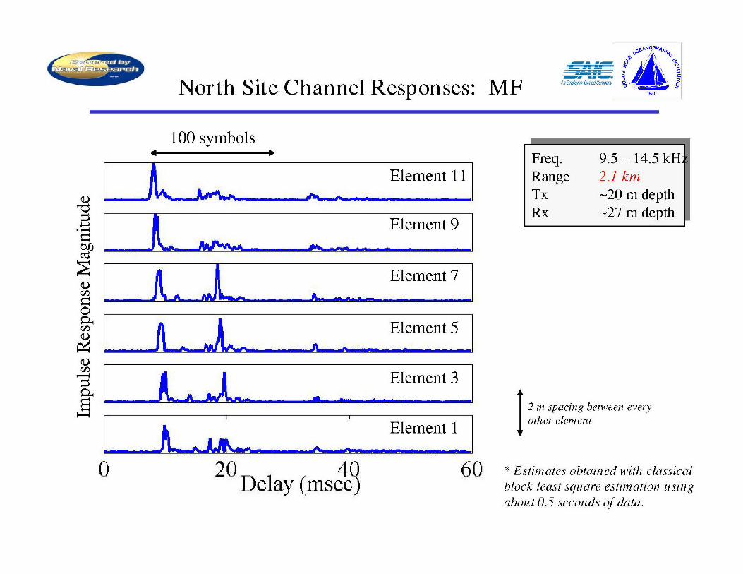
Figure 5. Channel impulse response amplitudes, as pressure on the number of degrees of freedom. Stressing
measured on rigid array for a high band signal at the North channel coherence times puts pressure on the required
site, are shown. In the top panel, responses are for each adaptation rate. These requirements are in conflict. One
array element while the bottom panel shows the response in possible solution is a more compact data representation than
beam space. delay and element taps.A second explanation arises from a careful
induced correlation between the signal stream estimates, each examination of the differing channel impulse responses. Thestream may be viewed as a parallel channel in the information hard bottom at the North site gave rise to an extended impulsetheoretic sense. The capacity estimate, C, is then given as: response at 1.7 km range (figure 5, top panel). Significant
energy continued to arrive 15 msec after the main arrival while
C = 0og2 ( + SNRo.,) (1) weaker reverberant energy stretched out well beyond that. In
par allel contrast, the South site impulse response showed significantchannels delay spreads of only 2 -3 msec. The delay spread is important

because successful spatial modulation requires that the Table 3. The demodulation performance for a hi-band signalequalizer be able to resolve the independent arrivals using the sent in the North site at 2.0 km range is shown when thefeedforward (as opposed to feedback) taps. In a time-varying equalizer operates in element space.channel, a performance penalty is generally incurred as thenumber of adapted degrees of freedom increase. Furthermore,with a sparse delay spread, an additional noise penalty is 1 Chan 2 Chan 3 Chanincurred for placing taps at delays with low signal energy. 11.3 5.6 2.5Once again, dispersion effects lead to degraded equalizer SNRoutperformance. (dB) - 4.4 1.3
By considering the physical nature of the channel,however, one might expect the later arrivals to have unique - - 1.6
angles of arrival. This observation suggests transforming thedata from element space to angle-of-arrival space. Figure 5 C 3.8 4.0 3.9(bottom panel) shows the beamformed impulse response at theNorth site. When the beamformer outputs are used rather than Table 4. The demodulation performance for a hi-band signalthe element data streams directly, the equalizer is no longer sent in the North site at 2.0 km range is shown when theencumbered with a lengthy delay spread in any given channel. equalizer operates in beam space.For signals that are not spatially modulated, common practicewould simply place feedback taps over the delayed arrivals.Spatial modulation, however, requires these late arrivals in thefeedforward structure and benefits from this transformation. 10.8 6.1 5.7The benefit is clear when examining SNROUt for these two cases. SNRou_Table 3 shows the performance of high band demodulation at (dB) - 6.1 5.82.7 km range in the North location when the equalizer is run inelement space. Table 4 shows the improvement when 5.9transformation to beam space is done prior to equalization. C 3.6 4.4 6.3While the non-spatially modulated signal is only slightlyaffected, the improvement in the spatially modulated signals ispronounced especially for 3 channels, as the later arrival ismade useful. and Finn Jensen for the opportunity to participate in the test and
V. CONCLUSIONS all they did to make it a success.
An effective receiver architecture has been presented VII. REFERENCES
that is suitable for decoding spatially modulated signals in theUAC. Using data collected jointly by the NATO Undersea 1. Kilfoyle, D. and A. Baggeroer, The State of the art inResearch Centre, SAIC, SPAWAR, the University of Delaware, underwater acoustic telemetry. IEEE Journal ofand the Woods Hole Oceanographic Institution in the waters Oceanic Engineering, 2000. 25(1): p. 4-27.offshore of Elba, Italy, spatial modulation was shown to offer 2. Frisk, G.V., Ocean and Seabed Acoustics: A Theorynearly a three-fold increase in capacity for the 9.6 - 12.4 kHz of Wave Propagation. 1994, Englewood Cliffs:band and nearly a two-fold increase in capacity for the 25 - 35 Prentice Hall. 299.kHz band. While the receiver architecture has features to 3. Stojanovic, M. et al., Phase-coherent digitalcompensate for channel dispersion, spatial modulation imposes communications for underwater acoustic channels.unique requirements that make the algorithm more susceptible IEEE Journal of Oceanic Engineering, 1994. 19(1): p.to performance degradation under severe dispersive conditions. 100-111.Such conditions were shown be limiting performance in these 4. Stojanovic, M. and Z. Zvonar, Multichanneltests rather than more classical criteria such as signal level or processing of broad-band multiuser communicationchannel transfer function rank. Future work will consider signals in shallow water acoustic channels. IEEEalgorithm modifications focused on these issues. Journal of Oceanic Engineering, 1996. 21(2): p. 156-
166.
VI. ACKNOWLEDGEMENTS 5. Al-Dhahir, N., Overview and comparison ofequalization schemes for space-time-coded signals
The authors wish to acknowledge the support of the with application to EDGE, IEEE Trans. on SignalOffice of Naval Research under the auspices of contracts Processing, 2002. 50(10): p. 2477-2488.N00014-97-1-0796 and N00014-01-C-0422. In addition, the 6. Duel-Hallen, A. and C. Heegard, Delayed decision-data collection would not have been possible without the feedback sequence estimation. IEEE Trans. onsupport of NATO Undersea Research Centre, the captain and Communicatiions, 1989. 37(5): p. 428-436.crew of the RNV Alliance and the Saralu, and the dedicated 7. Foschini, G. J., Layered space-time architecture fortechnical staff of the Woods Hole Oceanographic Institution. wireless communication in a fading environmentWe express our gratitude to Michael Porter, Martin Siderius, when using multiple antennas. Bell Laboratory
Technical Journal, 1996. 1(2): p. 41-59.

8. Ungerboeck, G., Channel coding withmultilevel/phase signals, IEEE Trans. on InformationTheory, 1982. 28(1).
9. Siwamogsatham, S. and M.P. Fitz, Robust space-timecodes for correlated Rayleigh fading channels. IEEETrans. on Signal Processing, 2002. 50(10): p. 2417-2428.
10. Jensen, F. B., et al., Results from the Elba HF-2003Experiment, in High-Frequency Ocean Acoustics,Eds. M. Porter, M. Siderius, W. Kuperman, AmericanInst. Physics Press (2004).

Spatial Modulation in the -if -oAn Employee-Owned Conpiny
Underwater Acoustic Channel
S•/l[•k\ gDaniel Kilfoyle, SAIC
Lee Freitag, WHOIMarch 17, 2004
1930

The Point of this Talk o 0AnErnpfoyce-Own aC rnpay ______1930
" The waveguide-nature of the underwater acoustic channel (UAC) makes it wellsuited for spatial modulation. However, underwater acoustic telemetry often facessevere temporal and frequency dispersion as compared to what many RF wirelessapplications encounter.
"* As RF MIMO efforts evolve (such as the DARPA Mobile Networked MIMOprogram), increasing bandwidth and mobility will emphasize the same issuescurrently faced by underwater acoustic MIMO channels. Thus, studying the UACholds broader value for the communications community.
"* Using data obtained during a 2003 at-sea test, three points will be made.
- An effective receiver algorithm has been developed that can both handle"spatial demodulation" and substantive dispersion.
- Time-varying channels with temporal dispersion may benefit from a pre-filter.
- Coherence and resolvability can lead to opposing array design pressures.

Discussion Roadmap 9 ; 10
"* A review of the modulation approach and a MIMO DFE/PLL receiver structure
"* A description of the at-sea testing conducted offshore of Elba, Italy
"* A summary of spatial modulation results via post-equalization SNR and capacity.
"* The impact of spatial coherence on spatial modulation performance
"* The consequences and mitigation of excessive temporal dispersion

P,0
ANA___________ CA Space-Time Coding Approach __ E0o 1
n bRate 112/126 burst error
X[n] {the bit stream correcting block code. Correctsany 4 consecutive bit errors.
Intleaveri
TCM Encoder:Option 1: Rate ½ code, QPSK output,
Constraint length = 3
Symbol buffers for the Option 2: Rate 2/3 code, 8PSK output,
Ntx transmitters Constraint length = 3Option 3: Rate 3/4 code, 16QAM output,
14 •Constraint length = 3
V-BLAST and D-BLAST use
Spatial interleaver cyclically switches to multiple, distinct coded bit
next Tx every symbol interval, streams, which is motivated bycomplexity concerns.

The Receiver Algorithm An 19300
Processing blocksfor each other data
1/T, FIR Filters stream
vj(t+N 1 T,) t A( -N TdlA Specialized -l/T Viterbi
its e/-& Algorithm-- S --. {ayi(n4•2
v,(t+N1TI) , - 1
tn
Error "Taps" for each of the
Signal other J- 1 concurrent
e. ( a e -d•)eJýt Phase- symbols are used to
SLocked Loop combat shadowing of
Synhroniz Lo_____Synchronize_____ l individual data streams.
using known Trained or c*i(n)channel probe Decision Directed
Adaptive Filter Update Feedback and Interference
Algorithm Cancellation Filters

P,0
Elba-2003 Test Methodology 1930
The Saralu'The Alliance
Range varied from
0.8 km to 11 km --- --..
Source Equipment Receive Equipment
6 Benthos AT-12ET transducers 14 element flexible hydrophone VLA (1 m spacing)- 9.5 to 14 kHz operating regime- 2 meter spacing in VLA 12 element rigid hydrophone VLA (6 in spacing)- Coherent and independently driven
48 channel record capability at 48 kHz sampling rate3 ITC-1032 transducers
- 25 to 35 kHz (only 6 dB loss up to 45 kHz) 24 channel record capability at 96 kHz sampling rate- 21 inch spacing in VLA- Coherent and independently driven Data streamed to SCSI disk in WAV format
enabling near real-time analysis

AENW M___i_ 004
An .® -0Elba-2003 Test Site
9050, 10°000 10010' 10020' 10030,
43020,' A 0 ISIOA S -/ North
CEO 111111111 ~lllSOUt
15020-
43010' 40
S 60-North Si.t •
43'00, '-CC
N -ck N80-
-- 30
1004 2 ° 5 0 ' - J , " 6 0 o 9 " P u=
,, .. . ... - ," 120 ,-1500 1510 1520 1530
A N- Sound Speed (m/s)" .. .130l- .. .. Track S
-140-150.. -- _,o1 .... South $ite'••:'I1890-
0-o - , Fornicbe di,, , . .- :-- ..... 210Depll onturs ll neles ',Grosseto Is."\Depth contours in metres Gro' t Is. . 420 301'N * Graphic from HF Elba-03 post
10 12 20' 30 40 SO' W°E cruise test report.
North Site Channel Responses: MF ý1930
100 symbols------- Freq. 9.5 - 14.5 k
L Element 11 Range 2.1 km, _mpg &___- - _ ,_........Tx -20 m depth
t -Rx -27 m depth5 Element 9
0 Element 7C~ __________ _ ______________--__
t t Element 5
" • _Element 3
S2 m spacing between every
Element 1 other element
0 20 4Q 60 * Estimates obtained with classicalDelay (msec) block least square estimation using
about 0.5 seconds of data.

South Site Channel Responses: MF o13 0
100 symbols--- Freq. 9.5 - 14.5 kH
A Element 11 Range 2.5 kmL ___Tx -20 m depth
Rx -27 m depthElement 9 _
A Element 7
Element 5
"Element 3
2miElement 1
0 20 40 60Delav (msec)
Spatial Modulation Performance o90
Assume an additive, white Gaussian
1 Chan 2 Chan 3 Chan 4 Chan 5 Chan 6 Chan noise model for each parallel channel.
16.1 11.4 8.7 7.4 5.3 3.7 Capacity- C = log 2 (1 + SNROUJ)
- 9.8 5.0 3.3 1.8 0.4 parallel
SNROut -- 7.7 5.9 2.3 1.6 channels
(dB) _ - 5.8 3.6 1.8 9.5 kHz - 14.5 kHz2.7 km range at South Site
S- - 4.3 3.0 Collected on 14 element array- - 1.3 SNRn/element - 30 dB
C 4.8 6.5 7.3 10.6 9.7 9.4 1 1
1 Chan 2 Chan 3 Chan 4 Chan 5 Chan 6 Chan9.5 kHz - 14.5 kHz 23.5 19.1 16.3 13.0 9.1 6.02.1 km range at North SiteCollected on 14 element array - 6 17.2 13.8 11.3 5.0SNRn/element - 27 dB (dB) 17.2 13.8 11.3 5.0
- 13.8 12.3 9.4
Similar signal levels and similar geometry - 8.4 3.9
but very different performance. Why? - I - - 8.3
C 7.6 13.1 17.1 23.0 21.9 17.6

One Possible Answer: Spatial Coherence o 0
9.5 kHz - 14.5 kHz 9.5 kHz - 14.5 kHz2.1 km range at North Site 2.7 km range at South SiteCollected on 14 element array Collected on 14 element arraySNRm/element - 27 dB SNRi./element - 30 dB
14 ii1 112--
i10 0.8 0.8
D8
6 0.6 0.6
2 I0.4 0.4
2 4 6 8 101214 2 4 6 8 101214Element # Element #
o While the cause of the reduced coherence at the North site is a subject for anotherinvestigation, spatial modulation clearly requires spatial coherence over time scales of theadaptive filter update process.
o The competing issues of path resolvability and spatial coherence warrant further study.* Correlation matrix averaged over 300 symbols (60 msec).

o ý,< , \ 0
Representat ionn &ye-Ole CompanAnother Possible Answer: DoF Rep esentation
Impulse Responses_ I I I I
2 Difficult to span this far I2T with feedforward taps. In beamspace, compact- filter support is possible.
4 6
6 8
-8 10
10 <12
12 , 14 , ,
0 10 20 30 40 50 0 5 10 15 20 25 30 351 Delay (msec) Delay (msec) I
1 Chan 2 Chan 3 Chan 1.7 km range I Chan 2Chan 3 Chan
11.3 5.6 2.5 North Site 10.8 6.1 5.7
(dB) - 4.4 1.3 (dB) - 6.1 5.8
- - 1.6 - - 5.9
C 3.8 4.0 3.9 C 3.6 4.4 6.3

P,0
Closing Thoughts An EflW[e-OWp aCorav _1930
" In this data set (and others), spatial modulation has been shown to offer two tothree fold improvements in capacity, even when the channel is intersymbolinterference limited and additional signal power is ineffective.
" Spatial coherence and multipath resolvability appear to impose opposing designconstraints in the underwater acoustic channel. Bigger may not be better indispersive MIMO channels.
" More compact representations of the signal space are particular important whenthe multipath (crucial for spatial modulation performance) is highly dispersed.Various sub-space based receiver algorithms may be indicated.
"* The UAC may offer valuable insights for future terrestrial MIMO applications.
" We would like to acknowledge the support of ONR, the HF-Elba03 test team,and the NATO Undersea Research Centre.