spatial reasoning for real-time robotic...
TRANSCRIPT

Spatial Reasoning for Real-time Robotic Manipulation
Han-Young Jang1, Hadi Moradi2, Suyeon Hong2, Sukhan Lee2, JungHyun Han1
1Department of Computer Science and Engineering 2School of Information and Communications EngineeringKorea University Sungkyunkwan University
Seoul, Korea Suwon, Korea
Abstract – Presented in this paper is an approach to real-time spatial reasoning for manipulative robotic tasks. When a service robot is requested to manipulate an object, it should determine the directions along which it can access and remove the object. The potential accessible directions for the object are retrieved from the object database. Then, spatial reasoning with the surrounding environment and the gripper geometry is invoked to verify the directions. The verification process mainly utilizes the visibility test of the commodity graphics hardware. Then, the directions along which both of the object and gripper are translated without colliding with the surrounding obstacles are computed using Minkowski sum and cube map of the graphics hardware. The access and removal directions are passed to the potential field path planning algorithm to determine the robot arm’s full path for accessing, removing and delivering the object. The experimental results show the feasibility of using graphics hardware for manipulative robotic tasks and further its performance gain in real-time manipulation. Index Terms – robotic manipulation, spatial reasoning, accessibility, graphics hardware.
I. INTRODUCTION
Recently, we have noticed a wide spectrum of efforts to extend robotics technology beyond industrial applications. Examples include mobile robots in the areas of service and personal assistance, especially for aiding the elderly or disabled. The research work presented in this paper aims at a mobile home service robot, which is equipped with a stereo camera mounted on a parallel jaw gripper. The mission of the service robot is to manipulate daily necessities on user’s request.
For such a mobile home service robot, a motion planner has been designed and implemented, which is composed of a 3D workspace modeling module [1], a spatial reasoning module, and a potential field path planning module [2]. This paper focuses on the algorithms of the spatial reasoning module, the main role of which is to determine the gripper access directions and object removal directions, i.e. the directions along which the robot gripper can access and remove the requested objects.
The success of a service robot depends on its real-time performance, and the above-mentioned three modules of the motion planner should run in real or interactive time. Unfortunately, software-based approaches to spatial reasoning are often too slow to be used for real-time manipulation. To tackle the problem, the spatial reasoning algorithms proposed in this paper have been implemented using graphics hardware.
Especially, the algorithms rely on the visibility query and environment map, which are supported by commodity graphics hardware. In the experiments, the graphics hardware proves to be quite useful for spatial reasoning, and guarantees the real-time performance.
The organization of this paper is as follows. Section II surveys the related work. Section III discusses 3D workspace modeling, and Section IV presents the gripper accessibility analysis. The major contribution of this paper is found in Section V, which discusses the spatial reasoning algorithms for determining the object removal directions. Section VI presents the experimental results, and evaluates the performance of the proposed approach. Finally, Section VII concludes the paper.
II. RELATED WORK
This paper proposes an accessibility analysis approach for accessing, grasping and removing objects. The proposed algorithms are based on the visibility query and environment map of graphics hardware. In general, accessibility analysis refers to a spatial reasoning activity that seeks to determine the directions along which a tool can access a target object. The major work in accessibility analysis has been done in the inspection field, especially with the coordinate measuring machines (CMMs) [3]. However, the application fields also include tool path planning for assembly [4], sensor placement for computer vision [5], numerically controlled machining [6], etc. In these fields, the proposed algorithms run mostly off-line to determine the accessibility. The accessibility analysis research report most relevant to our efforts can be found in [7], where the accessible directions for CMM tactile probes are computed using a cube map [8]. In the approach, however, it is assumed that the probe’s path to the workpiece is completely clear, i.e. only the workpiece may collide with the probe.
Since the very beginning of the computer graphics field, visibility test has been a fundamental problem. Among the visibility issues, the focus was dominantly on hidden surface removal. The problem has been mostly solved, and the z-buffer [9] technique dominates for interactive applications. In addition to the z-buffer, current commodity graphics hardware supports the image-space visibility query [11][12] that checks how many pixels of a given primitive are visible. Currently, the visibility query is supported both by OpenGL and DirectX.
In computer graphics, environment map, also called reflection map, is used to describe the scene surrounding an
object, and is usually represented as image textures [13]. Environment mapping starts with a ray from the viewpoint to a point on the reflector surface. The ray is reflected with respect to the surface normal, and then traced to provide an index to the image texture containing the environment. Popular implementations of the environment map include the cube map [8] and the sphere map [14].
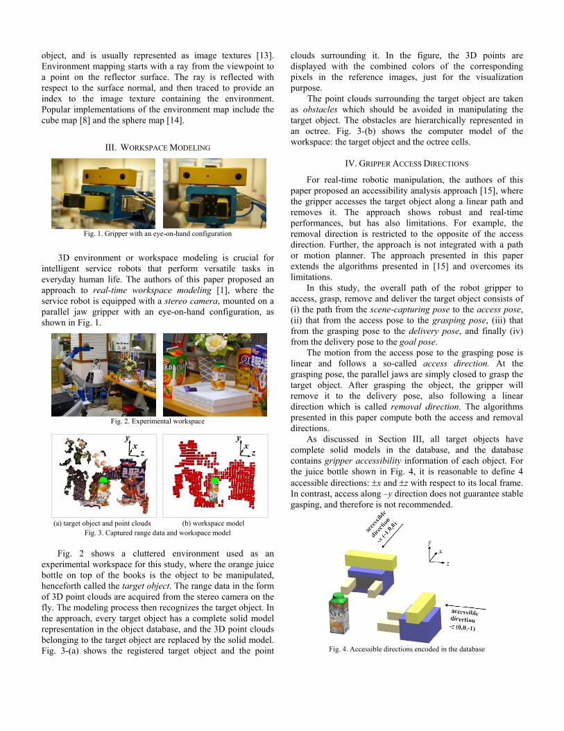
III. WORKSPACE MODELING
Fig. 1. Gripper with an eye-on-hand configuration
3D environment or workspace modeling is crucial for intelligent service robots that perform versatile tasks in everyday human life. The authors of this paper proposed an approach to real-time workspace modeling [1], where the service robot is equipped with a stereo camera, mounted on a parallel jaw gripper with an eye-on-hand configuration, as shown in Fig. 1.
Fig. 2. Experimental workspace
(a) target object and point clouds (b) workspace model
Fig. 3. Captured range data and workspace model
Fig. 2 shows a cluttered environment used as an experimental workspace for this study, where the orange juice bottle on top of the books is the object to be manipulated, henceforth called the target object. The range data in the form of 3D point clouds are acquired from the stereo camera on the fly. The modeling process then recognizes the target object. In the approach, every target object has a complete solid model representation in the object database, and the 3D point clouds belonging to the target object are replaced by the solid model. Fig. 3-(a) shows the registered target object and the point
clouds surrounding it. In the figure, the 3D points are displayed with the combined colors of the corresponding pixels in the reference images, just for the visualization purpose. The point clouds surrounding the target object are taken as obstacles which should be avoided in manipulating the target object. The obstacles are hierarchically represented in an octree. Fig. 3-(b) shows the computer model of the workspace: the target object and the octree cells.
IV. GRIPPER ACCESS DIRECTIONS
For real-time robotic manipulation, the authors of this paper proposed an accessibility analysis approach [15], where the gripper accesses the target object along a linear path and removes it. The approach shows robust and real-time performances, but has also limitations. For example, the removal direction is restricted to the opposite of the access direction. Further, the approach is not integrated with a path or motion planner. The approach presented in this paper extends the algorithms presented in [15] and overcomes its limitations.
In this study, the overall path of the robot gripper to access, grasp, remove and deliver the target object consists of (i) the path from the scene-capturing pose to the access pose, (ii) that from the access pose to the grasping pose, (iii) that from the grasping pose to the delivery pose, and finally (iv) from the delivery pose to the goal pose.
The motion from the access pose to the grasping pose is linear and follows a so-called access direction. At the grasping pose, the parallel jaws are simply closed to grasp the target object. After grasping the object, the gripper will remove it to the delivery pose, also following a linear direction which is called removal direction. The algorithms presented in this paper compute both the access and removal directions.
As discussed in Section III, all target objects have complete solid models in the database, and the database contains gripper accessibility information of each object. For the juice bottle shown in Fig. 4, it is reasonable to define 4 accessible directions: ±x and ±z with respect to its local frame. In contrast, access along –y direction does not guarantee stable gasping, and therefore is not recommended.
Fig. 4. Accessible directions encoded in the database
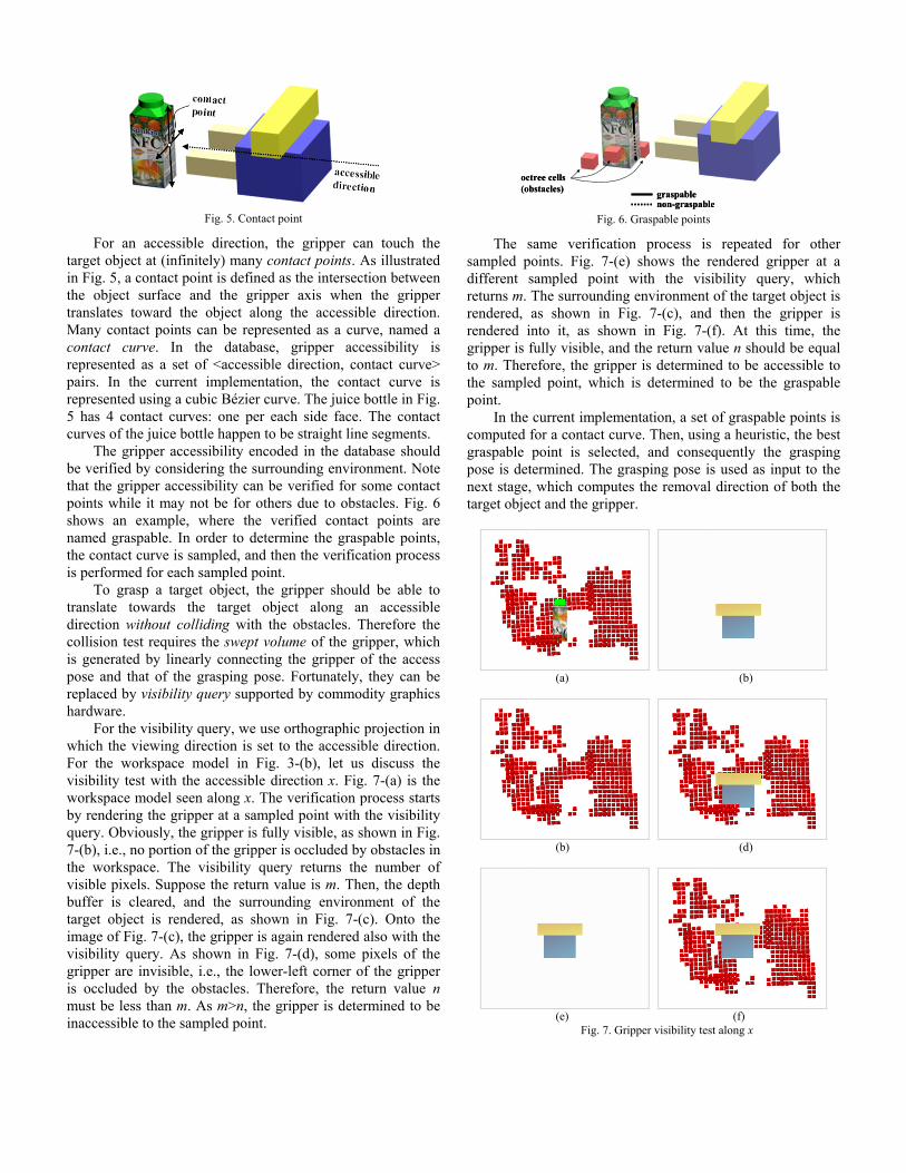
Fig. 5. Contact point
For an accessible direction, the gripper can touch the target object at (infinitely) many contact points. As illustrated in Fig. 5, a contact point is defined as the intersection between the object surface and the gripper axis when the gripper translates toward the object along the accessible direction. Many contact points can be represented as a curve, named a contact curve. In the database, gripper accessibility is represented as a set of <accessible direction, contact curve> pairs. In the current implementation, the contact curve is represented using a cubic Bézier curve. The juice bottle in Fig. 5 has 4 contact curves: one per each side face. The contact curves of the juice bottle happen to be straight line segments. The gripper accessibility encoded in the database should be verified by considering the surrounding environment. Note that the gripper accessibility can be verified for some contact points while it may not be for others due to obstacles. Fig. 6 shows an example, where the verified contact points are named graspable. In order to determine the graspable points, the contact curve is sampled, and then the verification process is performed for each sampled point. To grasp a target object, the gripper should be able to translate towards the target object along an accessible direction without colliding with the obstacles. Therefore the collision test requires the swept volume of the gripper, which is generated by linearly connecting the gripper of the access pose and that of the grasping pose. Fortunately, they can be replaced by visibility query supported by commodity graphics hardware. For the visibility query, we use orthographic projection in which the viewing direction is set to the accessible direction. For the workspace model in Fig. 3-(b), let us discuss the visibility test with the accessible direction x. Fig. 7-(a) is the workspace model seen along x. The verification process starts by rendering the gripper at a sampled point with the visibility query. Obviously, the gripper is fully visible, as shown in Fig. 7-(b), i.e., no portion of the gripper is occluded by obstacles in the workspace. The visibility query returns the number of visible pixels. Suppose the return value is m. Then, the depth buffer is cleared, and the surrounding environment of the target object is rendered, as shown in Fig. 7-(c). Onto the image of Fig. 7-(c), the gripper is again rendered also with the visibility query. As shown in Fig. 7-(d), some pixels of the gripper are invisible, i.e., the lower-left corner of the gripper is occluded by the obstacles. Therefore, the return value n must be less than m. As m>n, the gripper is determined to be inaccessible to the sampled point.
graspablenon-graspable
octree cells(obstacles) graspable
non-graspable
octree cells(obstacles)
Fig. 6. Graspable points
The same verification process is repeated for other sampled points. Fig. 7-(e) shows the rendered gripper at a different sampled point with the visibility query, which returns m. The surrounding environment of the target object is rendered, as shown in Fig. 7-(c), and then the gripper is rendered into it, as shown in Fig. 7-(f). At this time, the gripper is fully visible, and the return value n should be equal to m. Therefore, the gripper is determined to be accessible to the sampled point, which is determined to be the graspable point. In the current implementation, a set of graspable points is computed for a contact curve. Then, using a heuristic, the best graspable point is selected, and consequently the grasping pose is determined. The grasping pose is used as input to the next stage, which computes the removal direction of both the target object and the gripper.
(a) (b)
(b) (d)
(e) (f)
Fig. 7. Gripper visibility test along x

Fig. 8. Cube map
V. OBJECT REMOVAL DIRECTIONS
In computing the collision-free removal direction, environment map proves to be useful. The most popular implementation of the environment map is cube map [8], shown in Fig. 8, where each face covers a 90-degree field of view both horizontally and vertically. Therefore there are six faces per a cube, and each face is implemented as a square image texture. Notice that a pixel in the cube map represents a vector from the origin at the cube center.
Together with the cube map, Minkowski sum [16] proves to be useful for computing the removal direction. Suppose that the gripper is placed at a graspable point to make the grasping pose shown in Fig. 9-(a). Let us denote the combination of the object and gripper by O. For the point clouds P, the Minkowski sum of O and P is defined as the P-O. The point clouds P is simply a set of points, and therefore the Minkowski sum P-O is the union of -O located at each point pi in the point clouds. The number of points in the point clouds is often too huge. For the sake of real-time performance, not the points themselves but the octree cells are used for computing the Minkowski sum in the current implementation. Fig. 9-(b) visualizes the Minkowski sum P-O.
Placing the viewpoint (eye) at the center of the target object, the Minkowski sum is projected to a cube map. Projection is done per each square image of the cube map. Fig. 9-(c) shows the result, and Fig. 9-(d) is its unfolded version. In Fig. 9-(c) and -(d), the black-and-white image is used for obtaining the removable directions. The pixels which are not occupied by the projected Minkowski sum are colored in white, and represent the removable directions, along which no part of the target object or the gripper is occluded by the obstacles.
Out of the removable directions, one should be selected as the removal direction for path planning. In the current implementation, the following heuristic is used. Note that the removable directions form a set of connected components in the cube map surface, as shown in Fig. 9-(c). The connected components are simply identified using a labeling algorithm. The largest connected component and then its center pixel are selected. The selected pixel represents the removal direction. When the gripper removes the target object along the selected removal direction up to the delivery pose, it is more likely that the path planner will have the most freedom in determining the path from the delivery pose to the goal pose.
(a) grasping pose (b) Minkowski sum
(c) Minkowski sum projected onto cube map `
+y
-z +x +z -x
-y
(d) unfolded cube map
Fig. 9. Projection of Minkowski sum
Suppose that an acceptable removable direction has not been found from the cube map. It happens when the access direction and the graspable point have been verified but the gripper cannot remove the object along any direction. Then, the next-best graspable point is selected. (When all graspable points for an accessible direction are rejected, other accessible directions should be tested for verification.) With the newly selected graspable point, the stage for computing the removal direction is resumed, i.e. the griper is placed at the new graspable point to make a distinct grasping pose, and the Minkowski sum of the object and the gripper is projected to the cube map to find the removal direction.
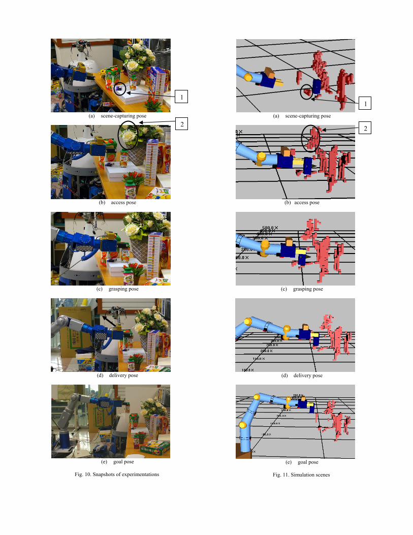
(a) scene-capturing pose
(b) access pose
(c) grasping pose
(d) delivery pose
(e) goal pose
Fig. 10. Snapshots of experimentations
1
(a) scene-capturing pose
1
2
(b) access pose
(c) grasping pose
(d) delivery pose
(e) goal pose
Fig. 11. Simulation scenes
2
VI. EXPERIMENTS
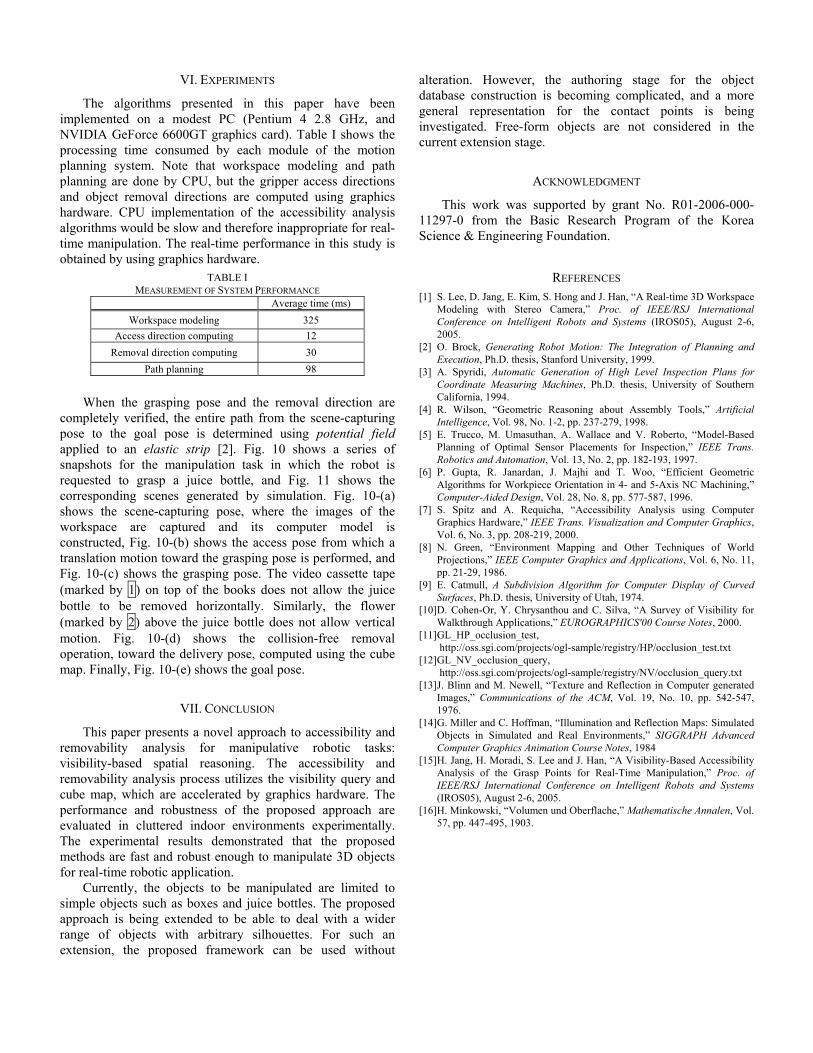
The algorithms presented in this paper have been implemented on a modest PC (Pentium 4 2.8 GHz, and NVIDIA GeForce 6600GT graphics card). Table I shows the processing time consumed by each module of the motion planning system. Note that workspace modeling and path planning are done by CPU, but the gripper access directions and object removal directions are computed using graphics hardware. CPU implementation of the accessibility analysis algorithms would be slow and therefore inappropriate for real-time manipulation. The real-time performance in this study is obtained by using graphics hardware.
When the grasping pcompletely verified, the epose to the goal pose iapplied to an elastic strsnapshots for the manipurequested to grasp a juicorresponding scenes geshows the scene-capturinworkspace are captureconstructed, Fig. 10-(b) stranslation motion towardFig. 10-(c) shows the gra(marked by 1) on top of bottle to be removed h(marked by 2) above the motion. Fig. 10-(d) soperation, toward the delimap. Finally, Fig. 10-(e) s
VII
This paper presents aremovability analysis visibility-based spatial removability analysis proccube map, which are accperformance and robustnevaluated in cluttered inThe experimental resultsmethods are fast and robufor real-time robotic applic
Currently, the objectsimple objects such as boapproach is being extendrange of objects with aextension, the proposed
alteration. However, the authoring stage for the object database construction is becoming complicated, and a more general representation for the contact points is being investigated. Free-form objects are not considered in the current extension stage.
ACKNOWLEDGMENT
This work was supported by grant No. R01-2006-000-11297-0 from the Basic Research Program of the Korea Science & Engineering Foundation.
REFERENCES MEASUREMENT
Workspace mode
Access direction comRemoval direction co
Path plannin
[1] S. Lee, D. Jang, E. Kim, S. Hong and J. Han, “A Real-time 3D Workspace Modeling with Stereo Camera,” Proc. of IEEE/RSJ International Conference on Intelligent Robots and Systems (IROS05), August 2-6, 2005.
[2] O. Brock, Generating Robot Motion: The Integration of Planning and Execution, Ph.D. thesis, Stanford University, 1999.
[3] A. Spyridi, Automatic Generation of High Level Inspection Plans for
TABLE I OF SYSTEM PERFORMANCE
Average time (ms) ling 325 puting 12
mputing 30 g 98
ose and the removal direction are ntire path from the scene-capturing s determined using potential field ip [2]. Fig. 10 shows a series of lation task in which the robot is
ce bottle, and Fig. 11 shows the nerated by simulation. Fig. 10-(a) g pose, where the images of the
d and its computer model is hows the access pose from which a the grasping pose is performed, and sping pose. The video cassette tape the books does not allow the juice orizontally. Similarly, the flower juice bottle does not allow vertical
hows the collision-free removal very pose, computed using the cube hows the goal pose.
. CONCLUSION
novel approach to accessibility and for manipulative robotic tasks: reasoning. The accessibility and ess utilizes the visibility query and
elerated by graphics hardware. The ess of the proposed approach are door environments experimentally. demonstrated that the proposed st enough to manipulate 3D objects ation.
s to be manipulated are limited to xes and juice bottles. The proposed ed to be able to deal with a wider rbitrary silhouettes. For such an framework can be used without
Coordinate Measuring Machines, Ph.D. thesis, University of Southern California, 1994.
[4] R. Wilson, “Geometric Reasoning about Assembly Tools,” Artificial Intelligence, Vol. 98, No. 1-2, pp. 237-279, 1998.
[5] E. Trucco, M. Umasuthan, A. Wallace and V. Roberto, “Model-Based Planning of Optimal Sensor Placements for Inspection,” IEEE Trans. Robotics and Automation, Vol. 13, No. 2, pp. 182-193, 1997.
[6] P. Gupta, R. Janardan, J. Majhi and T. Woo, “Efficient Geometric Algorithms for Workpiece Orientation in 4- and 5-Axis NC Machining,” Computer-Aided Design, Vol. 28, No. 8, pp. 577-587, 1996.
[7] S. Spitz and A. Requicha, “Accessibility Analysis using Computer Graphics Hardware,” IEEE Trans. Visualization and Computer Graphics, Vol. 6, No. 3, pp. 208-219, 2000.
[8] N. Green, “Environment Mapping and Other Techniques of World Projections,” IEEE Computer Graphics and Applications, Vol. 6, No. 11, pp. 21-29, 1986.
[9] E. Catmull, A Subdivision Algorithm for Computer Display of Curved Surfaces, Ph.D. thesis, University of Utah, 1974.
[10] D. Cohen-Or, Y. Chrysanthou and C. Silva, “A Survey of Visibility for Walkthrough Applications,” EUROGRAPHICS'00 Course Notes, 2000.
[11] GL_HP_occlusion_test, http://oss.sgi.com/projects/ogl-sample/registry/HP/occlusion_test.txt
[12] GL_NV_occlusion_query, http://oss.sgi.com/projects/ogl-sample/registry/NV/occlusion_query.txt
[13] J. Blinn and M. Newell, “Texture and Reflection in Computer generated Images,” Communications of the ACM, Vol. 19, No. 10, pp. 542-547, 1976.
[14] G. Miller and C. Hoffman, “Illumination and Reflection Maps: Simulated Objects in Simulated and Real Environments,” SIGGRAPH Advanced Computer Graphics Animation Course Notes, 1984
[15] H. Jang, H. Moradi, S. Lee and J. Han, “A Visibility-Based Accessibility Analysis of the Grasp Points for Real-Time Manipulation,” Proc. of IEEE/RSJ International Conference on Intelligent Robots and Systems (IROS05), August 2-6, 2005.
[16] H. Minkowski, “Volumen und Oberflache,” Mathematische Annalen, Vol. 57, pp. 447-495, 1903.