spatial reference manual - advanced navigation...spatial reference manual page 5 of 158 version 4.4...
TRANSCRIPT

Spatial Reference Manual

Spatial Reference ManualPage 1 of 158
Version 4.404/06/2019
Table of Contents1 Revision History........................................................................................................82 Firmware Changelog...............................................................................................133 Hardware Changelog..............................................................................................174 Introduction............................................................................................................185 Foundation Knowledge...........................................................................................19
5.1 GNSS...............................................................................................................195.2 INS................................................................................................................... 195.3 GNSS/INS.........................................................................................................195.4 AHRS............................................................................................................... 195.5 The Sensor Co-ordinate Frame........................................................................195.6 Roll, Pitch and Heading....................................................................................20
5.6.1 Second Right Hand Rule...........................................................................205.6.2 Rotation Order..........................................................................................21
5.7 Geodetic Co-ordinate System..........................................................................215.8 NED Co-ordinate Frame...................................................................................235.9 ECEF Co-ordinate Frame..................................................................................24
6 Evaluation Kit.........................................................................................................256.1 Evaluation Kit Contents...................................................................................256.2 Quick Start.......................................................................................................256.3 Troubleshooting...............................................................................................26
7 Part Numbers and Ordering Options.......................................................................277.1 Evaluation Kit..................................................................................................277.2 Standalone Unit...............................................................................................277.3 Accessories......................................................................................................27
8 Specifications.........................................................................................................298.1 Mechanical Drawings.......................................................................................298.2 Navigation Specifications................................................................................308.3 Sensor Specifications.......................................................................................318.4 GNSS Specifications.........................................................................................328.5 Communication Specifications.........................................................................328.6 Hardware Specifications..................................................................................338.7 Electrical Specifications...................................................................................348.8 Power Consumption.........................................................................................358.9 Connector Pin-out............................................................................................358.10 Evaluation Kit USB Cable...............................................................................368.11 Optional Breakout Cable................................................................................378.12 Sensor Calibration.........................................................................................388.13 Serial Number................................................................................................38
9 Installation..............................................................................................................409.1 Installation Checklist.......................................................................................409.2 Position and Alignment....................................................................................40
9.2.1 Alignment.................................................................................................419.3 Mounting Plate.................................................................................................419.4 Power Supply...................................................................................................419.5 GNSS Antenna.................................................................................................429.6 Odometer........................................................................................................43
9.6.1 Factory VSS Signal....................................................................................439.6.2 OBDII Odometer Interface........................................................................43
Spatial Reference ManualPage 2 of 158
Version 4.404/06/2019
9.6.3 Aftermarket Wheel Speed Sensor.............................................................439.6.4 Radar Speed Sensor.................................................................................44
9.7 Magnetics........................................................................................................449.8 Vibration..........................................................................................................45
10 Operation..............................................................................................................4610.1 Initialisation...................................................................................................46
10.1.1 Orientation Initialisation.........................................................................4610.1.2 Navigation Initialisation..........................................................................4610.1.3 Heading Initialisation..............................................................................4710.1.4 Time Initialisation...................................................................................47
10.2 Hot Start........................................................................................................4710.3 Time..............................................................................................................4710.4 Heading Source.............................................................................................48
10.4.1 Magnetic Heading...................................................................................4810.4.2 Velocity Heading.....................................................................................4810.4.3 External Heading....................................................................................48
10.5 Magnetics......................................................................................................4810.5.1 2D Magnetic Calibration.........................................................................49
10.5.1.1 Using the Spatial Manager Software................................................4910.5.1.2 Using the Packet Protocol................................................................49
10.5.2 3D Magnetic Calibration.........................................................................4910.5.2.1 Using the Spatial Manager Software................................................5010.5.2.2 Using the Packet Protocol................................................................50
10.5.3 Automatic Magnetic Calibration.............................................................5010.5.4 Disabling Magnetometers.......................................................................51
10.6 Sensors Range...............................................................................................5110.7 Data Anti Aliasing..........................................................................................5110.8 Vehicle Profiles..............................................................................................5110.9 Odometer Pulse Length.................................................................................51
10.9.1 Odometer Automatic Pulse Length Calibration Procedure......................5210.10 Reversing Detection....................................................................................5210.11 Motion Analysis............................................................................................5210.12 Differential and RTK GNSS...........................................................................5210.13 Raw Satellite Data.......................................................................................5310.14 Post Processing............................................................................................5310.15 Vents...........................................................................................................5410.16 RAIM............................................................................................................5410.17 Heave..........................................................................................................5410.18 Environmental Exposure..............................................................................55
10.18.1 Temperature.........................................................................................5510.18.2 Water....................................................................................................5510.18.3 Salt.......................................................................................................5510.18.4 Dirt and Dust........................................................................................5510.18.5 PH Level................................................................................................5510.18.6 Shocks..................................................................................................55
11 Spatial Manager....................................................................................................5711.1 Software Changelog......................................................................................5811.2 System Requirements....................................................................................5911.3 Installation.....................................................................................................5911.4 Troubleshooting.............................................................................................59
Spatial Reference ManualPage 3 of 158
Version 4.404/06/2019
11.4.1 All Platforms...........................................................................................5911.4.2 Windows.................................................................................................5911.4.3 Linux.......................................................................................................61
11.5 Main View......................................................................................................6211.5.1 Serial Port...............................................................................................6211.5.2 Attitude Indicator....................................................................................6211.5.3 Status Indicator......................................................................................62
11.5.3.1 Spatial Status Indicator...................................................................6311.5.3.2 Fix Indicator.....................................................................................6311.5.3.3 Satellites Table................................................................................63
11.5.4 3D Map...................................................................................................6311.5.5 3D Map Controls.....................................................................................63
11.5.5.1 Reset View.......................................................................................6311.5.5.2 Clear History....................................................................................63
11.6 Logging..........................................................................................................6311.7 View Menu.....................................................................................................64
11.7.1 Device Information.................................................................................6511.7.2 Status.....................................................................................................6511.7.3 Satellites.................................................................................................6611.7.4 Raw Sensors...........................................................................................6711.7.5 Orientation.............................................................................................6811.7.6 Position...................................................................................................6911.7.7 Velocity and Acceleration.......................................................................7011.7.8 3D Model................................................................................................7111.7.9 Communications Statistics.....................................................................7111.7.10 Heave...................................................................................................72
11.8 Configuration.................................................................................................7311.8.1 Configuration Export..............................................................................7311.8.2 Sensor Ranges........................................................................................7411.8.3 Filter Options..........................................................................................7411.8.4 Packet Rates...........................................................................................7511.8.5 Alignment Configuration.........................................................................76
11.8.5.1 Alignment Offset..............................................................................7611.8.5.2 GNSS Antenna Offset.......................................................................7611.8.5.3 Odometer Offset..............................................................................7711.8.5.4 External Data Offset........................................................................77
11.8.6 Baud Rates.............................................................................................7711.8.7 GPIO Configuration.................................................................................7711.8.8 Odometer...............................................................................................7811.8.9 Reset......................................................................................................7811.8.10 Reference Position Offsets....................................................................7911.8.11 GPIO Output Configuration...................................................................7911.8.12 Manual Initialisation..............................................................................8011.8.13 Gimbal..................................................................................................81
11.9 Tools..............................................................................................................8211.9.1 Terminal..................................................................................................8211.9.2 Magnetic Calibration...............................................................................8311.9.3 Firmware Update....................................................................................8411.9.4 Log Converter.........................................................................................8411.9.5 NTRIP Client............................................................................................84
Spatial Reference ManualPage 4 of 158
Version 4.404/06/2019
11.9.6 Network Connect....................................................................................8512 Interfacing............................................................................................................86
12.1 Communication.............................................................................................8612.1.1 Baud Rate...............................................................................................86
12.2 External Data.................................................................................................8612.3 GPIO Pins and Auxiliary RS232......................................................................8712.4 Dynamic Pin Functions...................................................................................87
12.4.1 1PPS Output...........................................................................................8912.4.2 GNSS Fix Output.....................................................................................8912.4.3 Odometer Input......................................................................................8912.4.4 Zero Velocity Input.................................................................................9012.4.5 Pitot Tube Input.......................................................................................9012.4.6 NMEA Input.............................................................................................9012.4.7 NMEA Output..........................................................................................9112.4.8 Novatel GNSS Input................................................................................9112.4.9 Topcon GNSS Input.................................................................................9212.4.10 ANPP Input............................................................................................9212.4.11 ANPP Output.........................................................................................9212.4.12 Disable Magnetometers........................................................................9212.4.13 Disable GNSS........................................................................................9212.4.14 Disable Pressure...................................................................................9212.4.15 Set Zero Orientation Alignment............................................................9212.4.16 System State Packet Trigger.................................................................9212.4.17 Raw Sensors Packet Trigger..................................................................9212.4.18 Pressure Depth Transducer...................................................................9312.4.19 RTCM Differential GNSS Corrections Input............................................9312.4.20 Trimble GNSS Input...............................................................................9312.4.21 u-blox GNSS Input.................................................................................9312.4.22 Hemisphere GNSS Input.......................................................................9312.4.23 Teledyne DVL Input...............................................................................9312.4.24 Tritech USBL Input................................................................................9312.4.25 Linkquest DVL Input.............................................................................9312.4.26 Linkquest USBL Input............................................................................9312.4.27 Nortek DVL Input..................................................................................9312.4.28 Left Wheel Speed Sensor......................................................................9412.4.29 Right Wheel Speed Sensor...................................................................9412.4.30 1PPS Input............................................................................................9412.4.31 Wheel Speed Sensor.............................................................................9412.4.32 Wheel Encoder Phase A........................................................................9412.4.33 Wheel Encoder Phase B........................................................................9412.4.34 Event 1 Input........................................................................................9412.4.35 Event 2 Input........................................................................................9412.4.36 TSS1 Output.........................................................................................9512.4.37 Simrad 1000 Output.............................................................................9512.4.38 Simrad 3000 Output.............................................................................9512.4.39 Serial Port Passthrough.........................................................................9512.4.40 GNSS Receiver Passthrough.................................................................9512.4.41 Gimbal Encoder Phase A.......................................................................9512.4.42 Gimbal Encoder Phase B.......................................................................9512.4.43 Odometer Direction, Forward Low........................................................95
Spatial Reference ManualPage 5 of 158
Version 4.404/06/2019
12.4.44 Odometer Direction, Forward High.......................................................9512.4.45 Reverse Alignment, Forward Low..........................................................9612.4.46 Reverse Alignment, Forward High........................................................9612.4.47 Zero Angular Velocity Input..................................................................96
13 Advanced Navigation Packet Protocol...................................................................9713.1 Data Types.....................................................................................................9713.2 Packet Structure............................................................................................97
13.2.1 Header LRC.............................................................................................9813.2.2 Packet ID................................................................................................9813.2.3 Packet Length.........................................................................................9813.2.4 CRC.........................................................................................................98
13.3 Packet Requests............................................................................................9813.4 Packet Acknowledgement..............................................................................9813.5 Packet Rates..................................................................................................9913.6 Packet Timing................................................................................................9913.7 Packet Summary............................................................................................9913.8 System Packets............................................................................................102
13.8.1 Acknowledge Packet.............................................................................10213.8.1.1 Acknowledge Result......................................................................102
13.8.2 Request Packet.....................................................................................10213.8.3 Boot Mode Packet.................................................................................103
13.8.3.1 Boot Mode Types...........................................................................10313.8.4 Device Information Packet....................................................................10313.8.5 Restore Factory Settings Packet............................................................10413.8.6 Reset Packet.........................................................................................104
13.8.6.1 Verification Sequence Values.........................................................10413.8.7 Serial Port Pass-through Packet............................................................104
13.8.7.1 Pass-through Routes......................................................................10413.9 State Packets...............................................................................................106
13.9.1 System State Packet.............................................................................10613.9.1.1 System Status...............................................................................10713.9.1.2 Filter Status...................................................................................10713.9.1.3 GNSS Fix Status.............................................................................10813.9.1.4 Unix Time Seconds........................................................................10813.9.1.5 Microseconds.................................................................................108
13.9.2 Unix Time Packet..................................................................................10913.9.3 Formatted Time Packet.........................................................................10913.9.4 Status Packet........................................................................................10913.9.5 Position Standard Deviation Packet......................................................11013.9.6 Velocity Standard Deviation Packet......................................................11013.9.7 Euler Orientation Standard Deviation Packet........................................11013.9.8 Quaternion Orientation Standard Deviation Packet..............................11013.9.9 Raw Sensors Packet..............................................................................11113.9.10 Raw GNSS Packet...............................................................................111
13.9.10.1 Raw GNSS Status.........................................................................11213.9.11 Satellites Packet.................................................................................11213.9.12 Detailed Satellites Packet...................................................................113
13.9.12.1 Satellite Systems.........................................................................11313.9.12.2 Satellite Frequencies...................................................................114
13.9.13 Geodetic Position Packet.....................................................................114

Spatial Reference ManualPage 6 of 158
Version 4.404/06/2019
13.9.14 ECEF Position Packet...........................................................................11413.9.15 UTM Position Packet............................................................................11513.9.16 NED Velocity Packet............................................................................11513.9.17 Body Velocity Packet...........................................................................11513.9.18 Acceleration Packet............................................................................11613.9.19 Body Acceleration Packet...................................................................11613.9.20 Euler Orientation Packet.....................................................................11613.9.21 Quaternion Orientation Packet...........................................................11713.9.22 DCM Orientation Packet......................................................................11713.9.23 Angular Velocity Packet......................................................................11813.9.24 Angular Acceleration Packet...............................................................11813.9.25 External Position & Velocity Packet.....................................................11813.9.26 External Position Packet......................................................................11913.9.27 External Velocity Packet.....................................................................11913.9.28 External Body Velocity Packet.............................................................11913.9.29 External Heading Packet.....................................................................12013.9.30 Running Time Packet..........................................................................12013.9.31 Local Magnetic Field Packet................................................................12113.9.32 Odometer State Packet.......................................................................12113.9.33 External Time Packet..........................................................................12113.9.34 External Depth Packet........................................................................12213.9.35 Geoid Height Packet...........................................................................12213.9.36 RTCM Corrections Packet....................................................................12213.9.37 External Pitot Pressure Packet............................................................12313.9.38 Wind Packet........................................................................................12313.9.39 Heave Packet......................................................................................12313.9.40 Post Processing Packet.......................................................................12313.9.41 Raw Satellite Data Packet...................................................................123
13.9.41.1 Satellite Frequencies...................................................................12513.9.41.2 Tracking Status............................................................................125
13.9.42 External Odometer Packet..................................................................12513.9.42.1 Odometer flags............................................................................126
13.9.43 External Air Data Packet.....................................................................12613.9.43.1 External Air Data Flags................................................................12613.9.43.2 Notes...........................................................................................126
13.9.44 Gimbal State Packet...........................................................................12713.9.45 Automotive Packet..............................................................................127
13.10 Configuration Packets................................................................................12813.10.1 Packet Timer Period Packet.................................................................128
13.10.1.1 UTC Synchronisation....................................................................12813.10.1.2 Packet Timer Period.....................................................................128
13.10.2 Packets Period Packet.........................................................................12813.10.2.1 Clear Existing Packets.................................................................12913.10.2.2 Packet Period...............................................................................129
13.10.3 Baud Rates Packet..............................................................................12913.10.4 Sensor Ranges Packet........................................................................130
13.10.4.1 Accelerometers Range.................................................................13013.10.4.2 Gyroscopes Range.......................................................................13013.10.4.3 Magnetometers Range................................................................130
13.10.5 Installation Alignment Packet.............................................................131
Spatial Reference ManualPage 7 of 158
Version 4.404/06/2019
13.10.5.1 Alignment DCM............................................................................13113.10.6 Filter Options Packet...........................................................................132
13.10.6.1 Vehicle Types...............................................................................13213.10.7 Advanced Filter Parameters Packet.....................................................13313.10.8 GPIO Configuration Packet..................................................................133
13.10.8.1 GPIO1 Functions..........................................................................13313.10.8.2 GPIO2 Functions..........................................................................13413.10.8.3 Auxiliary RS232 Transmit Functions.............................................13613.10.8.4 Auxiliary RS232 Receive Functions..............................................136
13.10.9 Magnetic Calibration Values Packet....................................................13813.10.10 Magnetic Calibration Configuration Packet.......................................138
13.10.10.1 Magnetic Calibration Actions.....................................................13813.10.11 Magnetic Calibration Status Packet..................................................139
13.10.11.1 Magnetic Calibration Status.......................................................13913.10.12 Odometer Configuration Packet........................................................14013.10.13 Set Zero Orientation Alignment Packet.............................................14013.10.14 Reference Point Offsets Packet.........................................................14013.10.15 GPIO Output Configuration Packet....................................................142
13.10.15.1 NMEA Fix Behaviour...................................................................14213.10.15.2 GPIO Output Rates.....................................................................14213.10.15.3 GPIO Output Rates Index...........................................................143
13.10.16 User Data Packet..............................................................................14313.10.17 GPIO Input Configuration Packet.......................................................144

Spatial Reference ManualPage 8 of 158
Version 4.404/06/2019
1 Revision History
Version Date Changes
4.4 04/06/2019 Updated firmware changelog, section 2Updated hardware changelog, section 3Updated dynamic pin functions table, section 12.4Updated GPIO configuration packet, section 13.10.8Added pressure depth transducer deprecated input function 12.4.18Added Nortek DVL input function 12.4.27Added Teledyne DVL input function 12.4.23Added Tritech USBL input function 12.4.24Added Linkquest DVL input function 12.4.25Added Linkquest USBL input functionality 12.4.26Added reverse alignment input functions 12.4.45Added zero angular velocity input function 12.4.47Clarified port baud rates in sections 8.5, 12.1, 12.3 and13.10.3Updated read status for external air data packet, section13.7Updated read status for external odometer packet, section13.7Modified quaternion element labels, sections 13.9.8 and13.9.21Clarified geoid height packet description, section 13.9.35Removed external pitot pressure packet, section 13.9.37Updated external body velocity packet size and definition13.9.28Updated specifications, section 8 Added RTK information, sections 10.12, 12.4.19Added wheel speed sensor specifications, section 12.4.31Corrected Raw GNSS packet velocity units, section 13.9.10Updated GPIO output configuration packet, section13.10.15Clarified negative acknowledgement packets, section13.8.1Clarified 1PPS output voltages, section 12.4.1
4.3 30/01/2017 Updated firmware changelog, section 2Updated hardware changelog, section 3Added raw satellite data operation, section 10.13Added post processing operation, section 10.14Added raw satellite data packet, section 13.9.41
4.2 12/04/2016 Updated firmware changelog, section 2Updated hardware changelog, section 3Updated images in foundation knowledge, section 5Added antenna offset diagrams, section 9.5Updated Spatial Manager changelog, section 11.1

Spatial Reference ManualPage 9 of 158
Version 4.404/06/2019
Version Date Changes
Updated sensor specifications with more detail, section 8.3
4.1 24/05/2015 Updated firmware changelog, section 2Updated hardware changelog, section 3Updated axes image, section 5.5Added part numbers and ordering information, section 7Updated optional breakout cable, section 8.11Updated power consumption graph, section 8.8Updated 2D magnetic calibration procedure, section 10.5.1Updated automatic magnetic calibration, section 10.5.3Added differential GNSS, section 10.12Updated Spatial Manager changelog, section 11.1Added gimbal encoder phase a function, section 12.4.41Added gimbal encoder phase b function, section 12.4.42Added odometer direction, forward low, section 12.4.43Added odometer direction, forward high, section 12.4.44Updated reset packet, section 13.8.6Updated UTM position packet, section 13.9.15Added gimbal state packet, section 13.9.44Added automotive packet, section 13.9.45Heave offsets packet changed name to reference point offsets packet, format remains the same, section 13.10.14Added user data packet, section 13.10.16Added GPIO input configuration packet, section 13.10.17Fixed a document heading spacing issue
4.0 18/09/2014 Added firmware changelog, section 2Added hardware changelog, section 3Updated GNSS specifications for version 3.0 hardware, section 8.4Updated connector pin-out to include pink wire, section 8.9Added evaluation kit USB cable, section 8.10Added optional breakout cable, section 8.11Added serial number information, section 8.13Updated GNSS antenna, section 9.5Updated OBDII Odometer, section 9.6.2Updated initialisation with more information, section 10.1Updated hot start for clarity, section 10.2Updated 2D magnetic calibration procedure for clarity, section 10.5.2.1Updated 3D magnetic calibration procedure for clarity, section 10.5.2.1Updated all screenshots in Spatial Manager, section 11Updated Spatial Manager changelog, section 11.1Updated Spatial Manager Linux troubleshooting, section11.4.3Added Spatial Manager 3D model, section 11.7.8Added Spatial Manager communications statistics, section11.7.9

Spatial Reference ManualPage 10 of 158
Version 4.404/06/2019
Version Date Changes
Added Spatial Manager GPIO output configuration, section11.8.11Added Spatial Manager position configuration, section11.8.12Added serial port pass-through GPIO function, section12.4.39Added packet timing, section 13.6Added serial port pass-through packet, section 13.8.7Changed raw GNSS packet, section 13.9.10Changed wind estimation packet to wind packet and changed from read only to read/write, section 13.9.38Added external odometer packet, section 13.9.42Added external air data packet, section 13.9.43Added stunt plane vehicle profile, section 13.10.6.1Updated set zero orientation packet, section 13.10.13NMEA output configuration packet changed to GPIO output configuration packet, section 13.10.15Total page numbering in header fixed
3.0 24/09/2013 Manual updated for Spatial v3.0 hardwareUpdated photo for Spatial v3.0 hardwareAdded evaluation kit, section 6Updated mechanical drawings, section 8.1Updated navigation specifications, section 8.2Updated sensor specifications, section 8.3Updated communication specifications, section 8.5Updated hardware specifications, section 8.6Updated electrical specifications, section 8.7Updated connector pin-out, section 8.9Updated mounting plate, section 9.3Updated odometer information, section 9.6Added reversing detection, section 10.10Added motion analysis, section 10.11Updated 3D magnetic calibration procedure, section 10.5.2Added automatic magnetic calibration, section 10.5.3Integrated Spatial Manager manual, section 11Added Auxiliary RS232 information, section 12.3Updated NMEA input, section 12.4.6Updated NMEA output, section 12.4.7Added wheel speed sensor function, section 12.4.31Added wheel encoder phase A function, section 12.4.32Added wheel encoder phase B function, section 12.4.33Added event 1 input, section 12.4.34Added event 2 input, section 12.4.35Added TSS1 output, section 12.4.36Added Simrad 1000 output, section 12.4.37Added Simrad 3000 output, section 12.4.38Updated filter status, section 13.9.1.2

Spatial Reference ManualPage 11 of 158
Version 4.404/06/2019
Version Date Changes
Added GNSS fix status, section 13.9.1.3Updated baud rates packet, section 13.10.3Updated filter options packet, section 13.10.6Updated GPIO configuration packet, section 13.10.8Added NMEA output configuration packet, section 13.10.15
2.7 27/03/2013 Added additional magnetic information, section 10.5Added 1PPS input, section 12.4.30Updated detailed satellites packet, section 13.9.12Corrected geoid height packet, section 13.9.35
2.6 29/01/2013 Added heave information, section 10.17Added RTCM corrections packet, section 13.9.36Added external pitot pressure packet, section 13.9.37Added wind estimation packet, section 13.9.38Added heave packet, section 13.9.39Added heave configuration packet, section 13.10.14
2.5 07/12/2012 Added input voltage range to electrical specifications, section 8.7Added left wheel speed sensor input, section 12.4.28Added right wheel speed sensor input, section 12.4.29Added external time packet, section 13.9.33Added external depth packet, section 13.9.34Added geoid height packet, section 13.9.35Updated GPIO functions tables, section 13.10.8
2.3 06/12/2012 Yaw terminology changed to heading for increased clarityReworded installation magnetics for increased clarity, section 9.7Reworded initialisation for increased clarity, section 10.1Reworded operation magnetics for increased clarity, section 10.5Added vehicle profiles information, section 10.8Updated NMEA output, section 12.4.7
2.2 19/11/2012 Installation magnetics changed, section 9.7Heading source added, section 10.4Disabling magnetometers changed, section 10.5.4GPIO information updated, section 12.3Added NMEA input GPGLL support, section 12.4.6Added NMEA input GPHDT support, section 12.4.6Added NMEA input HEHDT support, section 12.4.6Updated NMEA output, section 12.4.7Added RTCM corrections input, section 12.4.19Added Trimble GNSS input, section 12.4.20Added u-blox GNSS input, section 12.4.21Added Hemisphere GNSS input, section 12.4.22Updated GPIO functions tables, section 13.10.8
2.1 30/10/2012 Sensor specifications updated, section 8.3

Spatial Reference ManualPage 12 of 158
Version 4.404/06/2019
Version Date Changes
Fixed error in odometer state packet, section 13.9.32
2.0 18/10/2012 Added information on sensor calibration, section 8.12Added odometer installation information, section 9.6Added hot start information, section 10.2Added time information, section 10.3Added odometer pulse length information, section 10.9Added RAIM information, section 10.16Updated Odometer input, section 12.4.3Updated NMEA output, section 12.4.7Added disable magnetometers GPIO function, section12.4.12Added disable GNSS GPIO function, section 12.4.13Added disable pressure GPIO function, section 12.4.14Added set zero alignment GPIO function, section 12.4.15Added system state packet trigger GPIO function, section12.4.16Added raw sensors packet trigger GPIO function, section12.4.17Updated acknowledge packet, section 13.8.1Added running time packet, section 13.9.30Added local magnetic field packet, section 13.9.31Added odometer state packet, section 13.9.32Updated installation alignment packet, section 13.10.5Fixed error in filter options packet, section 13.10.6Updated GPIO configuration packet, section 13.10.8Added odometer configuration packet, section 13.10.12Added set zero orientation alignment packet, section13.10.13
1.0 16/09/2012 1PPS description updated, section 12.4.1Corrected reset packet, section 13.8.6Corrected external body velocity packet, section 13.9.28Revised alignment packet, section 13.10.5Grammar and spelling corrections
0.6 31/08/2012 Grammar corrections throughoutSpelling corrections throughoutUpdated 3D magnetic calibration, section 10.5.2
0.5 28/08/2012 Corrected satellite indexes, section 13.9.12.1Added navigation specifications, section 8.2Added sensor specifications, section 8.3Added GNSS specifications, section 8.4Added communication specifications, section 8.5Added hardware specifications, section 8.6
0.4 23/08/2012 Clarified anti aliasing, section 10.7Added external data, section 12.2Added GPIO information, section 12.3Added GPIO configuration packet, section 13.10.8

Spatial Reference ManualPage 13 of 158
Version 4.404/06/2019
Version Date Changes
0.3 11/08/2012 Magnetic calibration values packet correctedIncorrect length fixed on several packetsGrammar corrections
0.2 08/08/2012 Connector pin allocation table corrected
0.1 31/07/2012 First Draft
Table 1: Revision history
Spatial Reference ManualPage 14 of 158
Version 4.404/06/2019
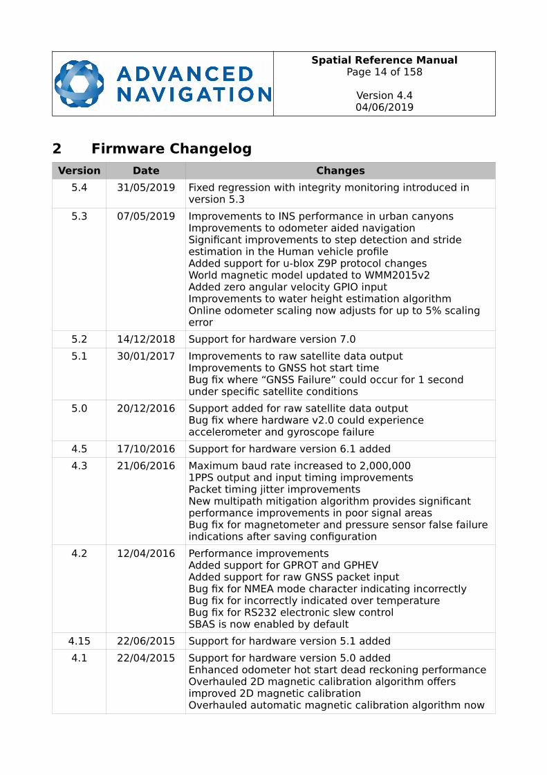
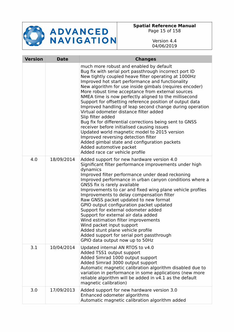
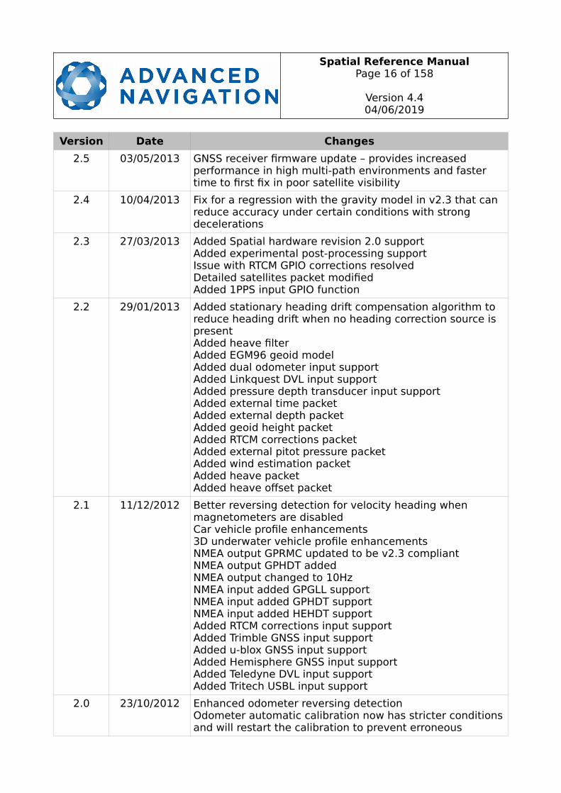
2 Firmware Changelog
Version Date Changes
5.4 31/05/2019 Fixed regression with integrity monitoring introduced in version 5.3
5.3 07/05/2019 Improvements to INS performance in urban canyonsImprovements to odometer aided navigationSignificant improvements to step detection and stride estimation in the Human vehicle profileAdded support for u-blox Z9P protocol changesWorld magnetic model updated to WMM2015v2Added zero angular velocity GPIO inputImprovements to water height estimation algorithmOnline odometer scaling now adjusts for up to 5% scaling error
5.2 14/12/2018 Support for hardware version 7.0
5.1 30/01/2017 Improvements to raw satellite data outputImprovements to GNSS hot start timeBug fix where “GNSS Failure” could occur for 1 second under specific satellite conditions
5.0 20/12/2016 Support added for raw satellite data outputBug fix where hardware v2.0 could experience accelerometer and gyroscope failure
4.5 17/10/2016 Support for hardware version 6.1 added
4.3 21/06/2016 Maximum baud rate increased to 2,000,0001PPS output and input timing improvementsPacket timing jitter improvementsNew multipath mitigation algorithm provides significant performance improvements in poor signal areasBug fix for magnetometer and pressure sensor false failure indications after saving configuration
4.2 12/04/2016 Performance improvementsAdded support for GPROT and GPHEVAdded support for raw GNSS packet inputBug fix for NMEA mode character indicating incorrectlyBug fix for incorrectly indicated over temperatureBug fix for RS232 electronic slew controlSBAS is now enabled by default
4.15 22/06/2015 Support for hardware version 5.1 added
4.1 22/04/2015 Support for hardware version 5.0 addedEnhanced odometer hot start dead reckoning performanceOverhauled 2D magnetic calibration algorithm offers improved 2D magnetic calibrationOverhauled automatic magnetic calibration algorithm now
Spatial Reference ManualPage 15 of 158
Version 4.404/06/2019
Version Date Changes
much more robust and enabled by defaultBug fix with serial port passthrough incorrect port IDNew tightly coupled heave filter operating at 1000HzImproved hot start performance and functionalityNew algorithm for use inside gimbals (requires encoder)More robust time acceptance from external sourcesNMEA time is now perfectly aligned to the millisecondSupport for offsetting reference position of output dataImproved handling of leap second change during operationVirtual odometer distance filter addedSlip filter addedBug fix for differential corrections being sent to GNSS receiver before initialised causing issuesUpdated world magnetic model to 2015 versionImproved reversing detection filterAdded gimbal state and configuration packetsAdded automotive packetAdded race car vehicle profile
4.0 18/09/2014 Added support for new hardware version 4.0Significant filter performance improvements under high dynamicsImproved filter performance under dead reckoningImproved performance in urban canyon conditions where a GNSS fix is rarely availableImprovements to car and fixed wing plane vehicle profilesImprovements to delay compensation filterRaw GNSS packet updated to new formatGPIO output configuration packet updatedSupport for external odometer addedSupport for external air data addedWind estimation filter improvementsWind packet input supportAdded stunt plane vehicle profileAdded support for serial port passthroughGPIO data output now up to 50Hz
3.1 10/04/2014 Updated internal AN RTOS to v4.0Added TSS1 output supportAdded Simrad 1000 output supportAdded Simrad 3000 output supportAutomatic magnetic calibration algorithm disabled due to variation in performance in some applications (new more reliable algorithm will be added in v4.1 as the default magnetic calibration)
3.0 17/09/2013 Added support for new hardware version 3.0Enhanced odometer algorithmsAutomatic magnetic calibration algorithm added
Spatial Reference ManualPage 16 of 158
Version 4.404/06/2019
Version Date Changes
2.5 03/05/2013 GNSS receiver firmware update – provides increased performance in high multi-path environments and faster time to first fix in poor satellite visibility
2.4 10/04/2013 Fix for a regression with the gravity model in v2.3 that can reduce accuracy under certain conditions with strong decelerations
2.3 27/03/2013 Added Spatial hardware revision 2.0 supportAdded experimental post-processing supportIssue with RTCM GPIO corrections resolvedDetailed satellites packet modifiedAdded 1PPS input GPIO function
2.2 29/01/2013 Added stationary heading drift compensation algorithm to reduce heading drift when no heading correction source is presentAdded heave filterAdded EGM96 geoid modelAdded dual odometer input supportAdded Linkquest DVL input supportAdded pressure depth transducer input supportAdded external time packetAdded external depth packetAdded geoid height packetAdded RTCM corrections packetAdded external pitot pressure packetAdded wind estimation packetAdded heave packetAdded heave offset packet
2.1 11/12/2012 Better reversing detection for velocity heading when magnetometers are disabledCar vehicle profile enhancements3D underwater vehicle profile enhancementsNMEA output GPRMC updated to be v2.3 compliantNMEA output GPHDT addedNMEA output changed to 10HzNMEA input added GPGLL supportNMEA input added GPHDT supportNMEA input added HEHDT supportAdded RTCM corrections input supportAdded Trimble GNSS input supportAdded u-blox GNSS input supportAdded Hemisphere GNSS input supportAdded Teledyne DVL input supportAdded Tritech USBL input support
2.0 23/10/2012 Enhanced odometer reversing detectionOdometer automatic calibration now has stricter conditionsand will restart the calibration to prevent erroneous
Spatial Reference ManualPage 17 of 158
Version 4.404/06/2019
Version Date Changes
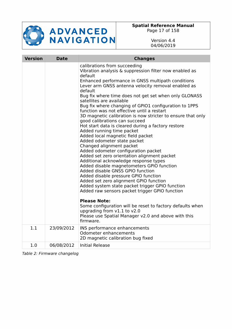
calibrations from succeedingVibration analysis & suppression filter now enabled as defaultEnhanced performance in GNSS multipath conditionsLever arm GNSS antenna velocity removal enabled as defaultBug fix where time does not get set when only GLONASS satellites are availableBug fix where changing of GPIO1 configuration to 1PPS function was not effective until a restart3D magnetic calibration is now stricter to ensure that only good calibrations can succeedHot start data is cleared during a factory restoreAdded running time packetAdded local magnetic field packetAdded odometer state packetChanged alignment packetAdded odometer configuration packetAdded set zero orientation alignment packetAdditional acknowledge response typesAdded disable magnetometers GPIO functionAdded disable GNSS GPIO functionAdded disable pressure GPIO functionAdded set zero alignment GPIO functionAdded system state packet trigger GPIO functionAdded raw sensors packet trigger GPIO function
Please Note: Some configuration will be reset to factory defaults when upgrading from v1.1 to v2.0Please use Spatial Manager v2.0 and above with this firmware.
1.1 23/09/2012 INS performance enhancementsOdometer enhancements2D magnetic calibration bug fixed
1.0 06/08/2012 Initial Release
Table 2: Firmware changelog
Spatial Reference ManualPage 18 of 158
Version 4.404/06/2019
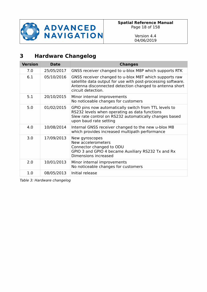
3 Hardware Changelog
Version Date Changes
7.0 25/05/2017 GNSS receiver changed to u-blox M8P which supports RTK
6.1 05/10/2016 GNSS receiver changed to u-blox M8T which supports raw satellite data output for use with post-processing software.Antenna disconnected detection changed to antenna short circuit detection.
5.1 20/10/2015 Minor internal improvementsNo noticeable changes for customers
5.0 01/02/2015 GPIO pins now automatically switch from TTL levels to RS232 levels when operating as data functionsSlew rate control on RS232 automatically changes based upon baud rate setting
4.0 10/08/2014 Internal GNSS receiver changed to the new u-blox M8 which provides increased multipath performance
3.0 17/09/2013 New gyroscopesNew accelerometersConnector changed to ODUGPIO 3 and GPIO 4 became Auxiliary RS232 Tx and RxDimensions increased
2.0 10/01/2013 Minor internal improvementsNo noticeable changes for customers
1.0 08/05/2013 Initial release
Table 3: Hardware changelog

Spatial Reference ManualPage 19 of 158
Version 4.404/06/2019
4 IntroductionSpatial is a miniature GNSS/INS & AHRS system that provides accurate position, velocity, acceleration and orientation under almost the most demanding conditions. It combines temperature calibrated accelerometers, gyroscopes, magnetometers and a pressure sensor with an advanced GNSS receiver. These are coupled in a sophisticatedfusion algorithm to deliver accurate and reliable navigation and orientation.
Spatial can provide amazing results but it does need to be set up properly and operated with an awareness of it’s limitations. Please read through this manual carefully to ensure success within your application.
The Spatial Manager software is downloadable from the software section of the Advanced Navigation website. It allows Spatial to be easily configured and operated. For more information on Spatial Manager please see section 11.
If you have any questions please contact [email protected].

Spatial Reference ManualPage 20 of 158
Version 4.404/06/2019
5 Foundation KnowledgeThis chapter is a learning reference that briefly covers knowledge essential to understanding Spatial and the following chapters. It explains the concepts in simple terms so that people unfamiliar with the technology may understand it.
5.1 GNSS
GNSS stands for global navigation satellite system. A GNSS consists of a number of satellites in space that broadcast navigation signals. These navigation signals can be picked up by a GNSS receiver on the earth to determine that receiver’s position and velocity. For a long time the only operational GNSS was the United States GPS. However the Russian GLONASS is now fully operational with similar performance to GPS. The Chinese BeiDou is in the process of becoming operational and the European Union’s GALILEO should be operational within ten years.
GNSS is excellent for navigational purposes and provides fairly accurate position (2.5 metres) and velocity (0.03 metres/second). The main drawback of GNSS is that the receiver must have a clear signal from at least 4 satellites to function. GNSS satellite signals are very weak and struggle to penetrate through buildings and other objects obstructing view of the sky. GNSS can also occasionally drop out due to disturbances inthe upper atmosphere.
5.2 INS
INS stands for inertial navigation system. An inertial navigation system can provide position and velocity similar to GNSS but with some big differences. The principle of inertial navigation is the measurement of acceleration. This acceleration is then integrated into velocity. The velocity is then integrated into position. Due to noise in the measurement and the compounding of that noise through the integration, inertial navigation has an error that increases exponentially over time. Inertial navigation systems have a very low relative error over short time periods but over long time periods the error can increase dramatically.
5.3 GNSS/INS
By combining GNSS and INS together in a mathematical algorithm, it is possible to take advantage of the benefits of GNSS long-term accuracy and INS short-term accuracy. This provides an overall enhanced position and velocity solution that can withstand short GNSS drop outs.
5.4 AHRS
AHRS stands for attitude and heading reference system. An AHRS uses accelerometers, gyroscopes and magnetometers combined in a mathematical algorithm to provide orientation. Orientation consists of the three body angles roll, pitch and heading.
Spatial Reference ManualPage 21 of 158
Version 4.404/06/2019
5.5 The Sensor Co-ordinate Frame
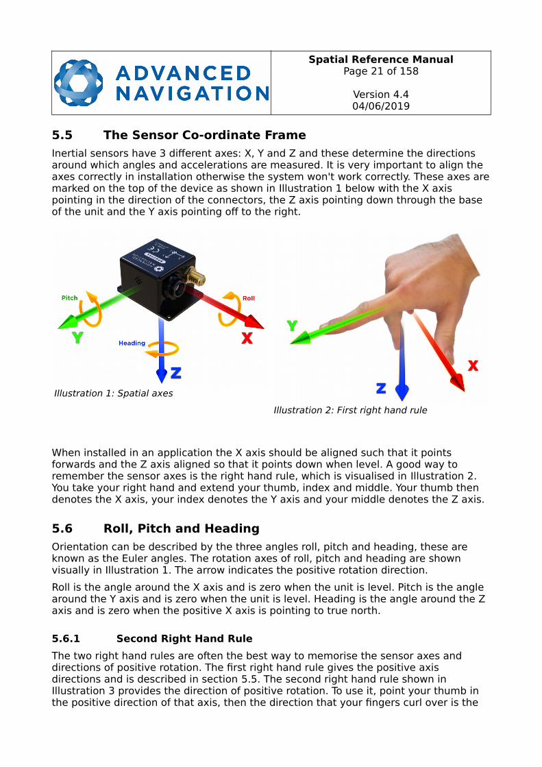
Inertial sensors have 3 different axes: X, Y and Z and these determine the directions around which angles and accelerations are measured. It is very important to align the axes correctly in installation otherwise the system won't work correctly. These axes aremarked on the top of the device as shown in Illustration 1 below with the X axis pointing in the direction of the connectors, the Z axis pointing down through the base of the unit and the Y axis pointing off to the right.
When installed in an application the X axis should be aligned such that it points forwards and the Z axis aligned so that it points down when level. A good way to remember the sensor axes is the right hand rule, which is visualised in Illustration 2. You take your right hand and extend your thumb, index and middle. Your thumb then denotes the X axis, your index denotes the Y axis and your middle denotes the Z axis.
5.6 Roll, Pitch and Heading
Orientation can be described by the three angles roll, pitch and heading, these are known as the Euler angles. The rotation axes of roll, pitch and heading are shown visually in Illustration 1. The arrow indicates the positive rotation direction.
Roll is the angle around the X axis and is zero when the unit is level. Pitch is the angle around the Y axis and is zero when the unit is level. Heading is the angle around the Z axis and is zero when the positive X axis is pointing to true north.
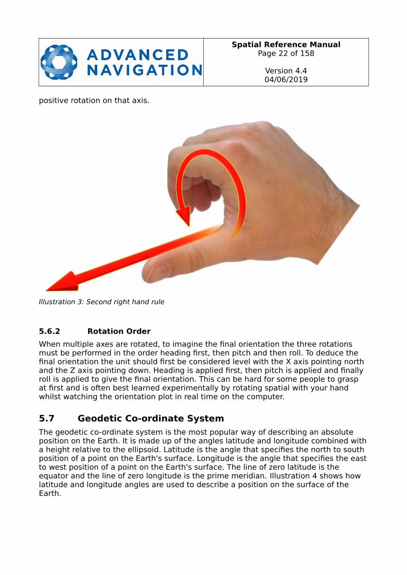
5.6.1 Second Right Hand Rule
The two right hand rules are often the best way to memorise the sensor axes and directions of positive rotation. The first right hand rule gives the positive axis directions and is described in section 5.5. The second right hand rule shown inIllustration 3 provides the direction of positive rotation. To use it, point your thumb in the positive direction of that axis, then the direction that your fingers curl over is the
Illustration 1: Spatial axes
Illustration 2: First right hand rule
Spatial Reference ManualPage 22 of 158
Version 4.404/06/2019
positive rotation on that axis.
5.6.2 Rotation Order
When multiple axes are rotated, to imagine the final orientation the three rotations must be performed in the order heading first, then pitch and then roll. To deduce the final orientation the unit should first be considered level with the X axis pointing north and the Z axis pointing down. Heading is applied first, then pitch is applied and finally roll is applied to give the final orientation. This can be hard for some people to grasp at first and is often best learned experimentally by rotating spatial with your hand whilst watching the orientation plot in real time on the computer.
5.7 Geodetic Co-ordinate System
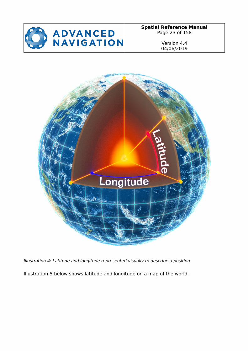
The geodetic co-ordinate system is the most popular way of describing an absolute position on the Earth. It is made up of the angles latitude and longitude combined witha height relative to the ellipsoid. Latitude is the angle that specifies the north to south position of a point on the Earth's surface. Longitude is the angle that specifies the eastto west position of a point on the Earth's surface. The line of zero latitude is the equator and the line of zero longitude is the prime meridian. Illustration 4 shows how latitude and longitude angles are used to describe a position on the surface of the Earth.
Illustration 3: Second right hand rule
Spatial Reference ManualPage 23 of 158
Version 4.404/06/2019
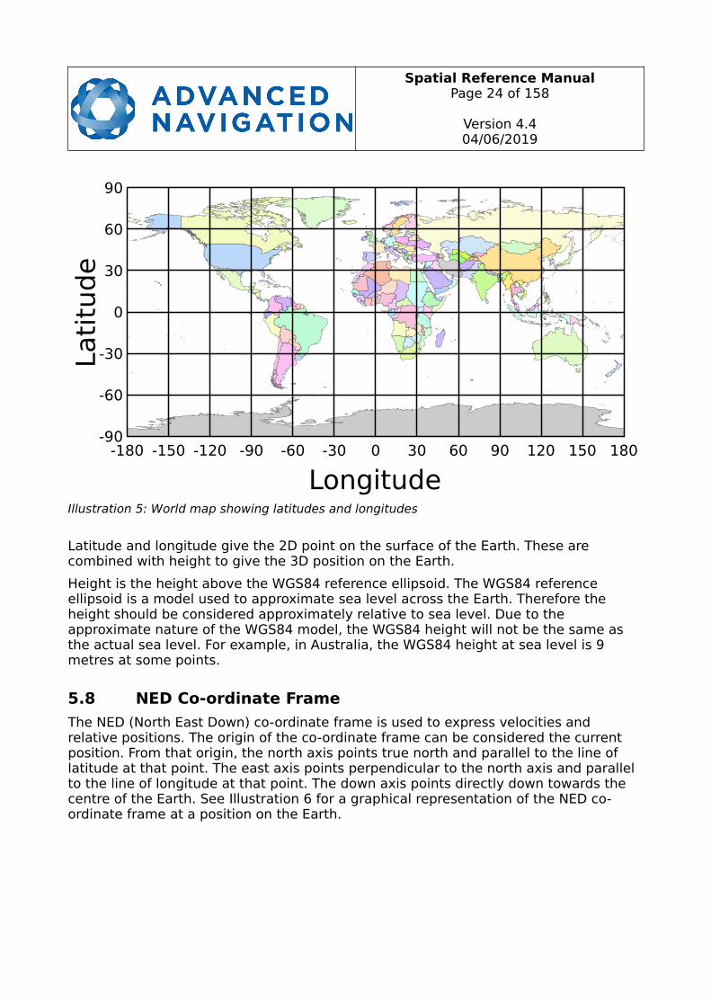
Illustration 5 below shows latitude and longitude on a map of the world.
Illustration 4: Latitude and longitude represented visually to describe a position
Spatial Reference ManualPage 24 of 158
Version 4.404/06/2019
Latitude and longitude give the 2D point on the surface of the Earth. These are combined with height to give the 3D position on the Earth.
Height is the height above the WGS84 reference ellipsoid. The WGS84 reference ellipsoid is a model used to approximate sea level across the Earth. Therefore the height should be considered approximately relative to sea level. Due to the approximate nature of the WGS84 model, the WGS84 height will not be the same as the actual sea level. For example, in Australia, the WGS84 height at sea level is 9 metres at some points.
5.8 NED Co-ordinate Frame
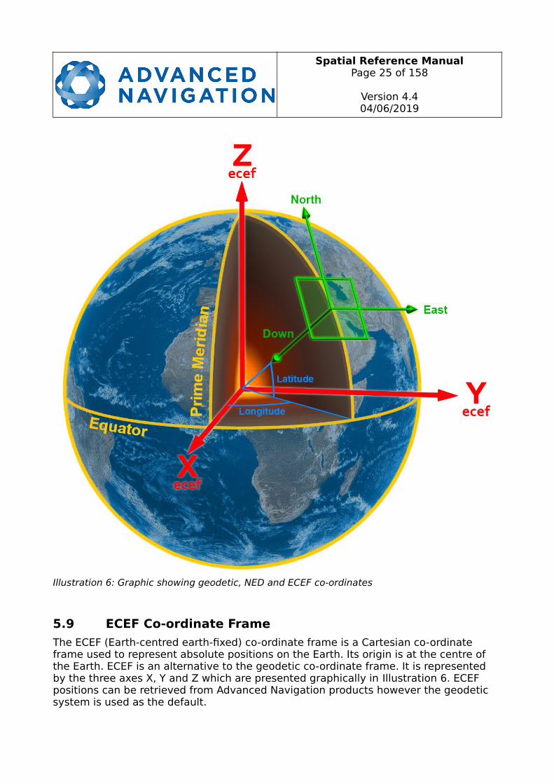
The NED (North East Down) co-ordinate frame is used to express velocities and relative positions. The origin of the co-ordinate frame can be considered the current position. From that origin, the north axis points true north and parallel to the line of latitude at that point. The east axis points perpendicular to the north axis and parallel to the line of longitude at that point. The down axis points directly down towards the centre of the Earth. See Illustration 6 for a graphical representation of the NED co-ordinate frame at a position on the Earth.
Illustration 5: World map showing latitudes and longitudes
Equator
Spatial Reference ManualPage 25 of 158
Version 4.404/06/2019
5.9 ECEF Co-ordinate Frame
The ECEF (Earth-centred earth-fixed) co-ordinate frame is a Cartesian co-ordinate frame used to represent absolute positions on the Earth. Its origin is at the centre of the Earth. ECEF is an alternative to the geodetic co-ordinate frame. It is represented by the three axes X, Y and Z which are presented graphically in Illustration 6. ECEF positions can be retrieved from Advanced Navigation products however the geodetic system is used as the default.
Illustration 6: Graphic showing geodetic, NED and ECEF co-ordinates
Spatial Reference ManualPage 26 of 158
Version 4.404/06/2019
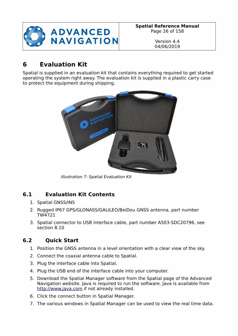
6 Evaluation KitSpatial is supplied in an evaluation kit that contains everything required to get started operating the system right away. The evaluation kit is supplied in a plastic carry case to protect the equipment during shipping.
6.1 Evaluation Kit Contents
1. Spatial GNSS/INS
2. Rugged IP67 GPS/GLONASS/GALILEO/BeiDou GNSS antenna, part number TW4721
3. Spatial connector to USB interface cable, part number A503-SDC20796, see section 8.10
6.2 Quick Start
1. Position the GNSS antenna in a level orientation with a clear view of the sky.
2. Connect the coaxial antenna cable to Spatial.
3. Plug the interface cable into Spatial.
4. Plug the USB end of the interface cable into your computer.
5. Download the Spatial Manager software from the Spatial page of the Advanced Navigation website. Java is required to run the software. Java is available from http://www.java.com if not already installed.
6. Click the connect button in Spatial Manager.
7. The various windows in Spatial Manager can be used to view the real time data.
Illustration 7: Spatial Evaluation Kit

Spatial Reference ManualPage 27 of 158
Version 4.404/06/2019
8. Once the unit is installed, perform a magnetic calibration. Please see section10.5.
9. Enter the GNSS antenna position offset into the alignment dialogue in Spatial Manager and press save, see section 11.8.5. The antenna offset is measured from the centre of the Spatial unit to the centre of the antenna in the body co-ordinate frame. Please note that as Z is positive down, if the antenna is above the Spatial unit this will result in a negative Z value.
10.To view the data logs, click disconnect in Spatial Manager. In the tools menu, select log converter and press convert. The *.anpp binary log file will be converted to CSV files that can be opened with popular data processing programs such as Matlab or Microsoft Excel. The log files can be found in the same folder as the Spatial Manager software.
6.3 Troubleshooting
1. If you are having trouble opening Spatial Manager, please try reinstalling Java.
2. If you are having problems connecting to Spatial, please try reinstalling the latest FTDI driver from the FTDI website: http://www.ftdichip.com/Drivers/VCP.htm
3. If you are running Spatial at a high update rate under Windows the latency timer will need to be adjusted. To do this please open control panel → system → device manager → ports → right click USB Serial Port → properties → port settings → advanced. In this window change the latency timer to 1 millisecond. Please see section 11.4.2 for more detail.
Spatial Reference ManualPage 28 of 158
Version 4.404/06/2019
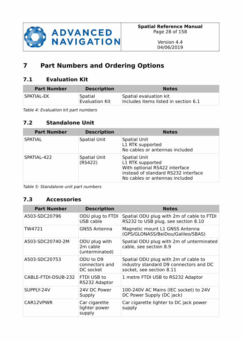
7 Part Numbers and Ordering Options
7.1 Evaluation Kit
Part Number Description Notes
SPATIAL-EK Spatial Evaluation Kit
Spatial evaluation kitIncludes items listed in section 6.1
Table 4: Evaluation kit part numbers
7.2 Standalone Unit
Part Number Description Notes
SPATIAL Spatial Unit Spatial UnitL1 RTK supportedNo cables or antennas included
SPATIAL-422 Spatial Unit (RS422)
Spatial UnitL1 RTK supportedWith optional RS422 interfaceinstead of standard RS232 interfaceNo cables or antennas included
Table 5: Standalone unit part numbers
7.3 Accessories
Part Number Description Notes
A503-SDC20796 ODU plug to FTDI USB cable
Spatial ODU plug with 2m of cable to FTDI RS232 to USB plug, see section 8.10
TW4721 GNSS Antenna Magnetic mount L1 GNSS Antenna (GPS/GLONASS/BeiDou/Galileo/SBAS)
A503-SDC20740-2M ODU plug with 2m cable (unterminated)
Spatial ODU plug with 2m of unterminatedcable, see section 8.9
A503-SDC20753 ODU to D9 connectors and DC socket
Spatial ODU plug with 2m of cable to industry standard D9 connectors and DC socket, see section 8.11
CABLE-FTDI-DSUB-232 FTDI USB to RS232 Adaptor
1 metre FTDI USB to RS232 Adaptor
SUPPLY-24V 24V DC Power Supply
100-240V AC Mains (IEC socket) to 24V DC Power Supply (DC jack)
CAR12VPWR Car cigarette lighter power supply
Car cigarette lighter to DC jack power supply

Spatial Reference ManualPage 29 of 158
Version 4.404/06/2019
Part Number Description Notes
OBDII-ODOMETER OBDII Odometer OBDII Odometer InterfaceSee section 9.6.2
AD-UNIT Air Data Unit Air data unit provides pitot and static air data aiding for Spatial in fixed wing aircraft
ILU Interface and Logging Unit
Interface and logging unit provides an Ethernet interface to Spatial with built in logging, time server and more ports
Table 6: Accessories part numbers
Spatial Reference ManualPage 30 of 158
Version 4.404/06/2019
8 Specifications
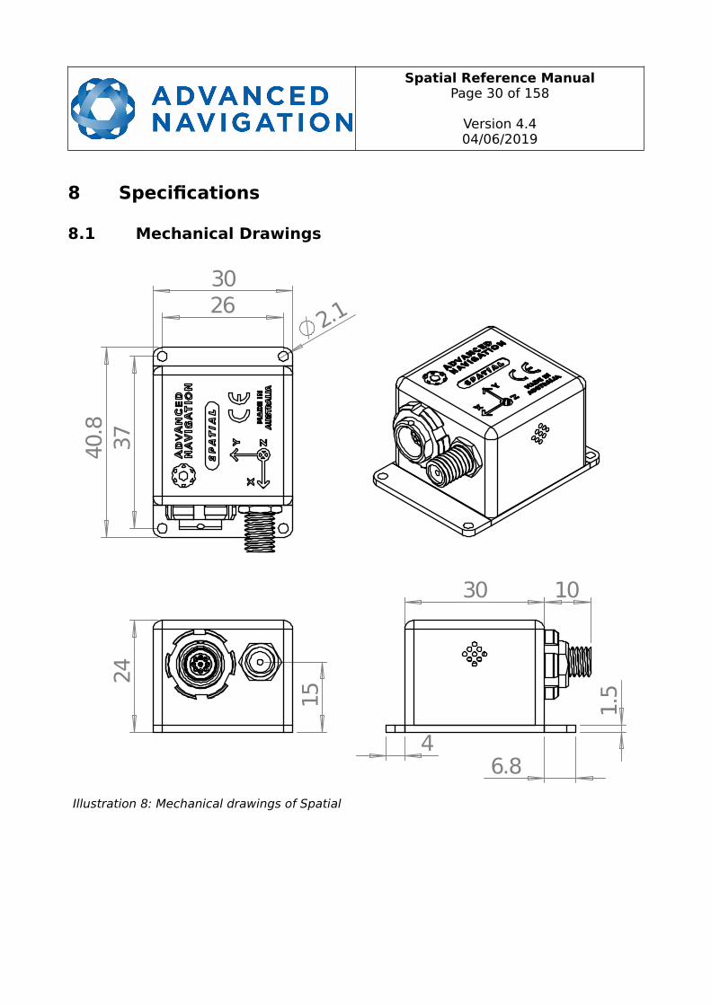
8.1 Mechanical Drawings
Illustration 8: Mechanical drawings of Spatial

Spatial Reference ManualPage 31 of 158
Version 4.404/06/2019
8.2 Navigation Specifications
Parameter Value
Horizontal Position Accuracy 2.0 m
Vertical Position Accuracy 3.0 m
Horizontal Position Accuracy (with L1 RTK) 0.02 m
Vertical Position Accuracy (with L1 RTK) 0.03 m
Velocity Accuracy 0.05 m/s
Roll & Pitch Accuracy (Static) 0.1 °
Heading Accuracy (Static) 0.5 °
Roll & Pitch Accuracy (Dynamic) 0.2 °
Heading Accuracy (Dynamic with GNSS) 0.2 °
Heading Accuracy (Dynamic, magnetic only)
0.8 °
Heave Accuracy 5 % or 0.05 m, whichever is greater
Orientation Range Unlimited
Hot Start Time 500 ms
Internal Filter Rate 1000 Hz
Output Data Rate Up to 1000 Hz
Table 7: Navigation specifications
Spatial Reference ManualPage 32 of 158
Version 4.404/06/2019
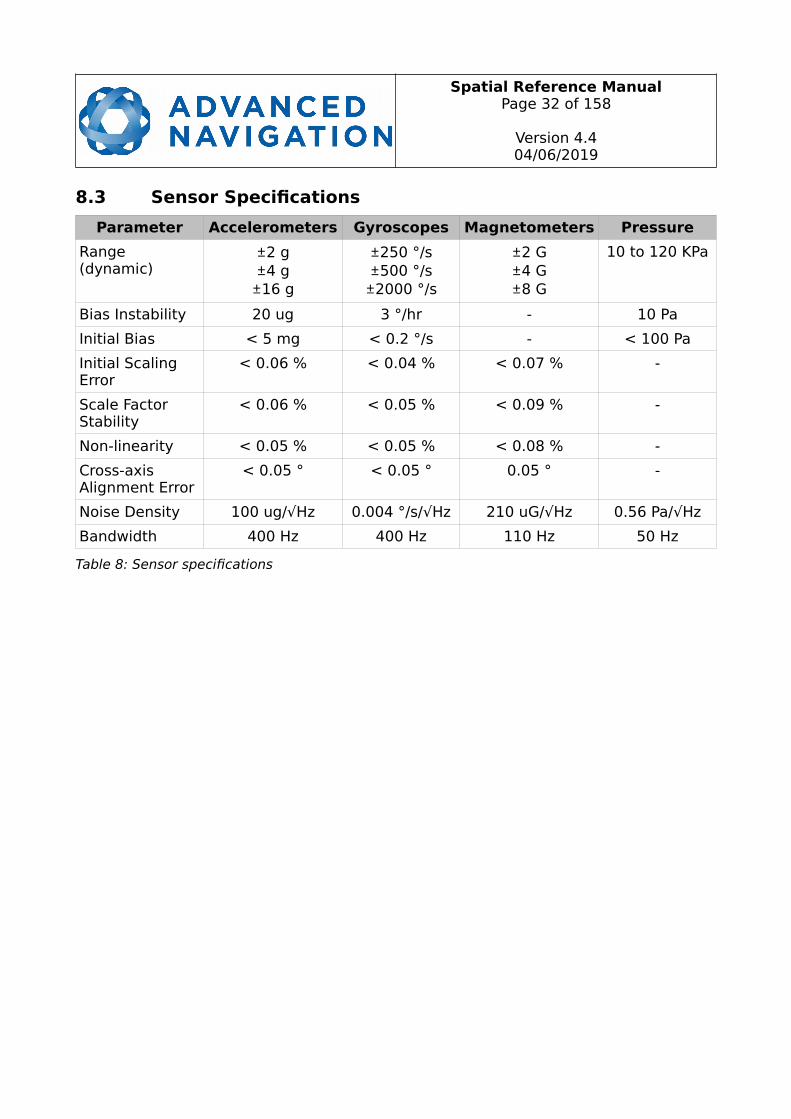
8.3 Sensor Specifications
Parameter Accelerometers Gyroscopes Magnetometers Pressure
Range(dynamic)
±2 g±4 g±16 g
±250 °/s±500 °/s±2000 °/s
±2 G±4 G±8 G
10 to 120 KPa
Bias Instability 20 ug 3 °/hr - 10 Pa
Initial Bias < 5 mg < 0.2 °/s - < 100 Pa
Initial Scaling Error
< 0.06 % < 0.04 % < 0.07 % -
Scale Factor Stability
< 0.06 % < 0.05 % < 0.09 % -
Non-linearity < 0.05 % < 0.05 % < 0.08 % -
Cross-axis Alignment Error
< 0.05 ° < 0.05 ° 0.05 ° -
Noise Density 100 ug/√Hz 0.004 °/s/√Hz 210 uG/√Hz 0.56 Pa/√Hz
Bandwidth 400 Hz 400 Hz 110 Hz 50 Hz
Table 8: Sensor specifications

Spatial Reference ManualPage 33 of 158
Version 4.404/06/2019
8.4 GNSS Specifications
Parameter Value
Supported Navigation Systems GPS L1GLONASS L1GALILEO E1BeiDou B1
Supported SBAS Systems WAASEGNOSMSAS
GAGANQZSS
Update Rate 10 Hz
Cold Start Sensitivity -148 dBm
Tracking Sensitivity -160 dBm
Hot Start First Fix 1 s
Cold Start First Fix 26 s
Horizontal Position Accuracy 2.5 m
Horizontal Position Accuracy (with L1 RTK) 0.02 m
Velocity Accuracy 0.05 m/s
Timing Accuracy 30 ns
Acceleration Limit 4 g
Table 9: GNSS specifications
8.5 Communication Specifications
Parameter Value
Interface RS232 (RS422 optional)
Primary and Auxiliary Port Speed 2400 to 2 M baud
GPIO Port Speed 2400 to 250 K baud
Protocol AN Packet ProtocolNMEATSS1
Simrad
Peripheral Interface 2 x GPIO and Auxiliary RS232
GPIO Level 5 V or RS232
Table 10: Communication specifications
Spatial Reference ManualPage 34 of 158
Version 4.404/06/2019
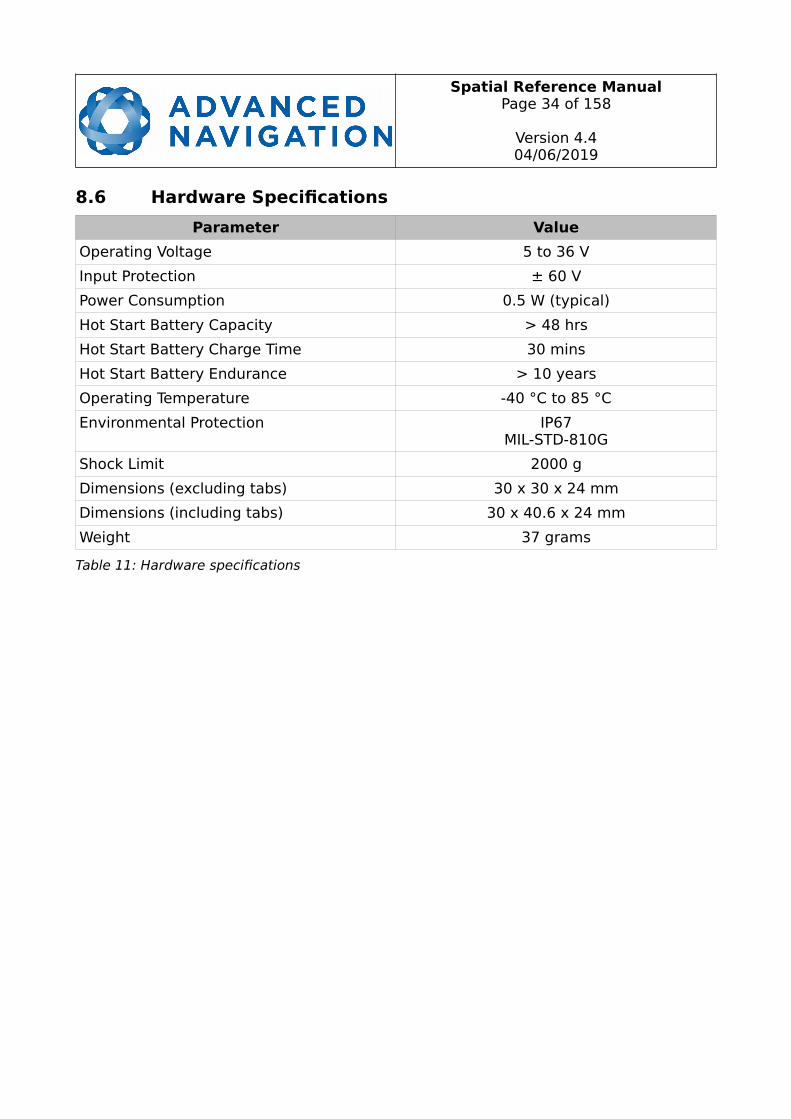
8.6 Hardware Specifications
Parameter Value
Operating Voltage 5 to 36 V
Input Protection ± 60 V
Power Consumption 0.5 W (typical)
Hot Start Battery Capacity > 48 hrs
Hot Start Battery Charge Time 30 mins
Hot Start Battery Endurance > 10 years
Operating Temperature -40 °C to 85 °C
Environmental Protection IP67MIL-STD-810G
Shock Limit 2000 g
Dimensions (excluding tabs) 30 x 30 x 24 mm
Dimensions (including tabs) 30 x 40.6 x 24 mm
Weight 37 grams
Table 11: Hardware specifications
Spatial Reference ManualPage 35 of 158
Version 4.404/06/2019
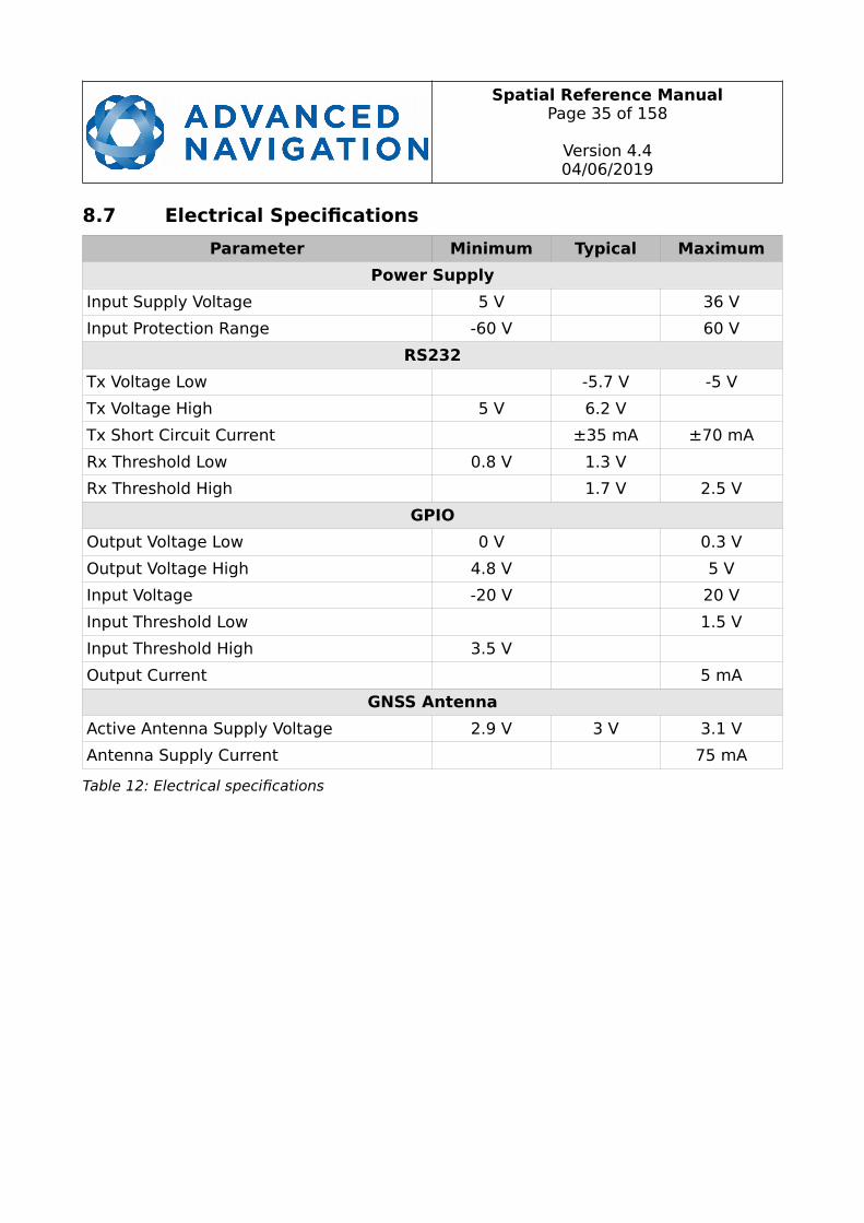
8.7 Electrical Specifications
Parameter Minimum Typical Maximum
Power Supply
Input Supply Voltage 5 V 36 V
Input Protection Range -60 V 60 V
RS232
Tx Voltage Low -5.7 V -5 V
Tx Voltage High 5 V 6.2 V
Tx Short Circuit Current ±35 mA ±70 mA
Rx Threshold Low 0.8 V 1.3 V
Rx Threshold High 1.7 V 2.5 V
GPIO
Output Voltage Low 0 V 0.3 V
Output Voltage High 4.8 V 5 V
Input Voltage -20 V 20 V
Input Threshold Low 1.5 V
Input Threshold High 3.5 V
Output Current 5 mA
GNSS Antenna
Active Antenna Supply Voltage 2.9 V 3 V 3.1 V
Antenna Supply Current 75 mA
Table 12: Electrical specifications

Spatial Reference ManualPage 36 of 158
Version 4.404/06/2019
8.8 Power Consumption
Illustration 9: Maximum and typical current consumption across operating voltage
2 4 6 8 10 12 14 16 18 20 22 24 26 28 30 32 34 36 380
20
40
60
80
100
120
140
Maximum
Typical
Voltage (V)
Cu
rre
nt C
on
sum
ptio
n (
mA
)
Spatial Reference ManualPage 37 of 158
Version 4.404/06/2019
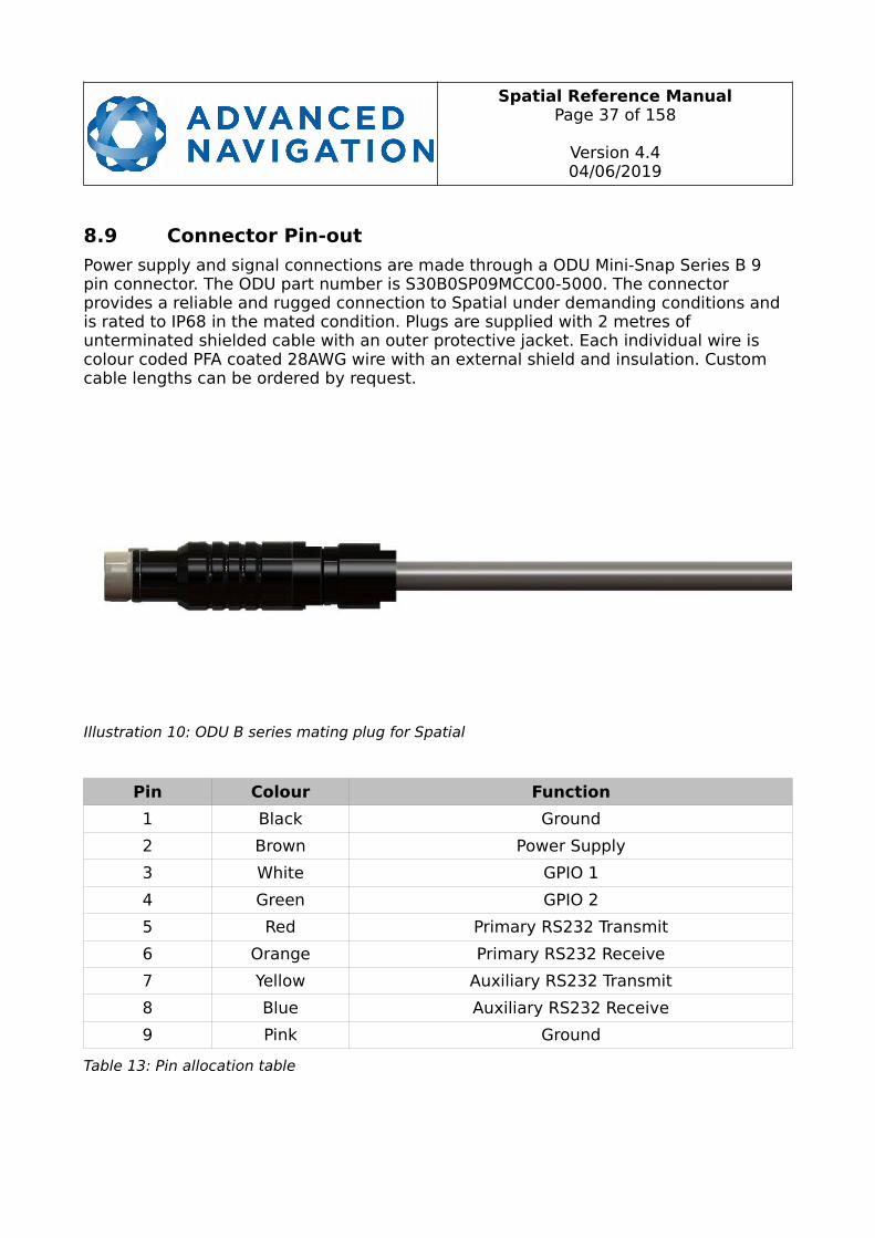
8.9 Connector Pin-out
Power supply and signal connections are made through a ODU Mini-Snap Series B 9 pin connector. The ODU part number is S30B0SP09MCC00-5000. The connector provides a reliable and rugged connection to Spatial under demanding conditions and is rated to IP68 in the mated condition. Plugs are supplied with 2 metres of unterminated shielded cable with an outer protective jacket. Each individual wire is colour coded PFA coated 28AWG wire with an external shield and insulation. Custom cable lengths can be ordered by request.
Pin Colour Function
1 Black Ground
2 Brown Power Supply
3 White GPIO 1
4 Green GPIO 2
5 Red Primary RS232 Transmit
6 Orange Primary RS232 Receive
7 Yellow Auxiliary RS232 Transmit
8 Blue Auxiliary RS232 Receive
9 Pink Ground
Table 13: Pin allocation table
Illustration 10: ODU B series mating plug for Spatial
Spatial Reference ManualPage 38 of 158
Version 4.404/06/2019
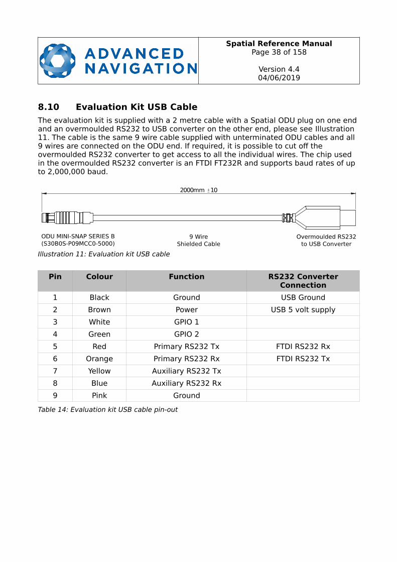
8.10 Evaluation Kit USB Cable
The evaluation kit is supplied with a 2 metre cable with a Spatial ODU plug on one endand an overmoulded RS232 to USB converter on the other end, please see Illustration 11. The cable is the same 9 wire cable supplied with unterminated ODU cables and all 9 wires are connected on the ODU end. If required, it is possible to cut off the overmoulded RS232 converter to get access to all the individual wires. The chip used in the overmoulded RS232 converter is an FTDI FT232R and supports baud rates of up to 2,000,000 baud.
Pin Colour Function RS232 ConverterConnection
1 Black Ground USB Ground
2 Brown Power USB 5 volt supply
3 White GPIO 1
4 Green GPIO 2
5 Red Primary RS232 Tx FTDI RS232 Rx
6 Orange Primary RS232 Rx FTDI RS232 Tx
7 Yellow Auxiliary RS232 Tx
8 Blue Auxiliary RS232 Rx
9 Pink Ground
Table 14: Evaluation kit USB cable pin-out
Illustration 11: Evaluation kit USB cable
Spatial Reference ManualPage 39 of 158
Version 4.404/06/2019
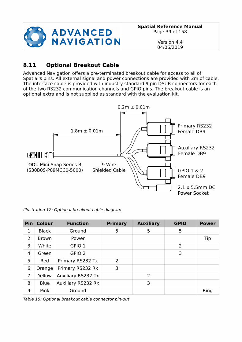
8.11 Optional Breakout Cable
Advanced Navigation offers a pre-terminated breakout cable for access to all of Spatial's pins. All external signal and power connections are provided with 2m of cable.The interface cable is provided with industry standard 9 pin DSUB connectors for each of the two RS232 communication channels and GPIO pins. The breakout cable is an optional extra and is not supplied as standard with the evaluation kit.
Pin Colour Function Primary Auxiliary GPIO Power
1 Black Ground 5 5 5
2 Brown Power Tip
3 White GPIO 1 2
4 Green GPIO 2 3
5 Red Primary RS232 Tx 2
6 Orange Primary RS232 Rx 3
7 Yellow Auxiliary RS232 Tx 2
8 Blue Auxiliary RS232 Rx 3
9 Pink Ground Ring
Table 15: Optional breakout cable connector pin-out
Illustration 12: Optional breakout cable diagram
Spatial Reference ManualPage 40 of 158
Version 4.404/06/2019
8.12 Sensor Calibration
Spatial's sensors are calibrated for bias, sensitivity, misalignment, cross-axis sensitivity, non-linearity and gyroscope linear acceleration sensitivity across the full operating temperature range and for each of the three sensor ranges.
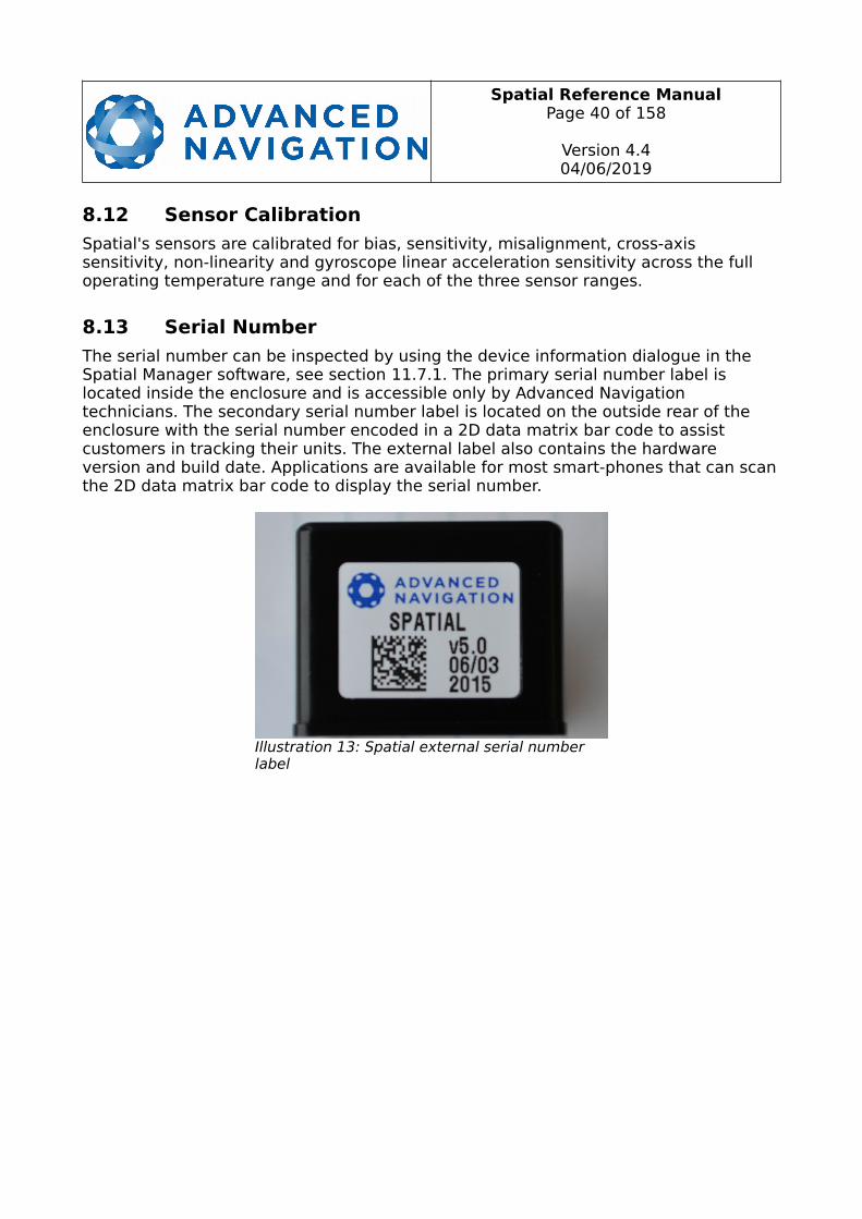
8.13 Serial Number
The serial number can be inspected by using the device information dialogue in the Spatial Manager software, see section 11.7.1. The primary serial number label is located inside the enclosure and is accessible only by Advanced Navigation technicians. The secondary serial number label is located on the outside rear of the enclosure with the serial number encoded in a 2D data matrix bar code to assist customers in tracking their units. The external label also contains the hardware version and build date. Applications are available for most smart-phones that can scanthe 2D data matrix bar code to display the serial number.
Illustration 13: Spatial external serial number label

Spatial Reference ManualPage 41 of 158
Version 4.404/06/2019
9 Installation
9.1 Installation Checklist
1. Securely mount the unit to the vehicle following the guidelines in section 9.2.
2. Mount the GNSS antenna to the vehicle following the guidelines in section 9.5 and then connect the antenna to Spatial unit.
3. Connect the connector cable to Spatial and then connect the USB end to a computer.
4. Open the Spatial Manager software on the computer and click connect.
5. If the unit is mounted in an alignment other than standard alignment of X pointing forward and Z pointing down, this alignment offset will need to be entered into the Alignment Configuration dialogue in Spatial Manager. Please see section 9.2.1 for more details.
6. Accurately measure the primary GNSS antenna offset from the centre of the Spatial unit to the centre of the antenna in the body co-ordinate frame (X positive forward and Z positive down) and enter these values into the AlignmentConfiguration dialogue in Spatial Manager. Please note that the body axes are always X positive forward and Z positive down irrespective of any alignment offset entered in the previous step.
7. Enter the vehicle type in the Filter Options dialogue in Spatial Manager.
8. Perform a magnetic calibration on the unit as described in section 10.5. If magnetic calibration is going to be too difficult to perform on the vehicle or the operating environment has high levels of magnetic interference then it is recommended to disable magnetic heading in Filter Options and use only GNSS velocity heading. If magnetic heading is disabled a magnetic calibration does not need to be performed.
9. The system is now ready for use.
9.2 Position and Alignment
When installing Spatial into a vehicle, correct positioning and alignment are essential to achieve good performance. There are a number of goals in selecting a mounting site in your application, these are:
1. Spatial should be mounted away from high levels of vibration where possible.
2. Spatial should be mounted in an area that is not going to exceed its temperature range and mounted in a manner that will properly dissipate heat; please contact [email protected] for advice specific to your application.
3. The two vents on the sides of Spatial should not be obstructed.
4. If magnetic heading is going to be used, Spatial should be mounted at least 0.5 metres away from sources of dynamic magnetic interference i.e. high current wiring, large motors, moving steel masses and rotating or reciprocating

Spatial Reference ManualPage 42 of 158
Version 4.404/06/2019
machinery.
5. Spatial should be mounted close to the centre of gravity of the vehicle where possible.
6. Spatial should be mounted within several metres of the GNSS antenna where possible.
9.2.1 Alignment
The easiest way to align Spatial is by installing it with the sensor axes aligned with thevehicle axes. This means that the X axis points forward towards the front of the vehicle and the Z axis points down towards the ground.
If aligning Spatial with the vehicle axes is not possible or not optimal, it may be mounted in a different alignment and the alignment offset should be configured using the Spatial Manager software, see section 11.8.5. For easy alignment, the set zero orientation button in the Spatial Manager alignment dialogue can be used to set the current orientation as the level alignment, see section 11.8.5. Please note that this willonly correct for roll and pitch offsets. Any heading offset will need to be entered manually and saved after using this function.
9.3 Mounting Plate
Spatial's mounting plate and hole guide is shown below in Illustration 14. The holes aredesigned for M2 cap screws.
9.4 Power Supply
A high level of power supply filtering has been built into Spatial, however it is stillrecommended that the power supply be free of significant noise. As thecommunications ground is shared with the supply ground, it is important to ensurethat ground wiring is routed to avoid power supply noise from other systemscorrupting data communications.
Illustration 14: Spatial mounting plate
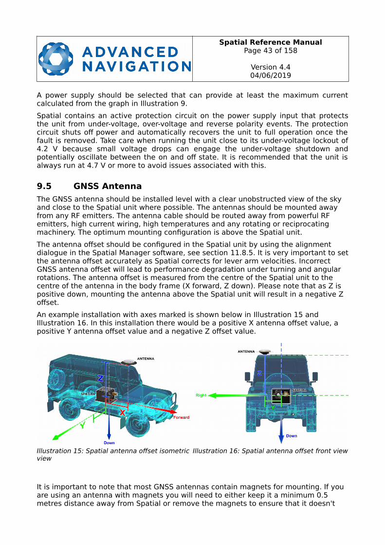
Spatial Reference ManualPage 43 of 158
Version 4.404/06/2019
A power supply should be selected that can provide at least the maximum currentcalculated from the graph in Illustration 9.
Spatial contains an active protection circuit on the power supply input that protectsthe unit from under-voltage, over-voltage and reverse polarity events. The protectioncircuit shuts off power and automatically recovers the unit to full operation once thefault is removed. Take care when running the unit close to its under-voltage lockout of4.2 V because small voltage drops can engage the under-voltage shutdown andpotentially oscillate between the on and off state. It is recommended that the unit isalways run at 4.7 V or more to avoid issues associated with this.
9.5 GNSS Antenna
The GNSS antenna should be installed level with a clear unobstructed view of the sky and close to the Spatial unit where possible. The antennas should be mounted away from any RF emitters. The antenna cable should be routed away from powerful RF emitters, high current wiring, high temperatures and any rotating or reciprocating machinery. The optimum mounting configuration is above the Spatial unit.
The antenna offset should be configured in the Spatial unit by using the alignment dialogue in the Spatial Manager software, see section 11.8.5. It is very important to setthe antenna offset accurately as Spatial corrects for lever arm velocities. Incorrect GNSS antenna offset will lead to performance degradation under turning and angular rotations. The antenna offset is measured from the centre of the Spatial unit to the centre of the antenna in the body frame (X forward, Z down). Please note that as Z is positive down, mounting the antenna above the Spatial unit will result in a negative Z offset.
An example installation with axes marked is shown below in Illustration 15 andIllustration 16. In this installation there would be a positive X antenna offset value, a positive Y antenna offset value and a negative Z offset value.
It is important to note that most GNSS antennas contain magnets for mounting. If you are using an antenna with magnets you will need to either keep it a minimum 0.5 metres distance away from Spatial or remove the magnets to ensure that it doesn't
Illustration 15: Spatial antenna offset isometric view
Illustration 16: Spatial antenna offset front view
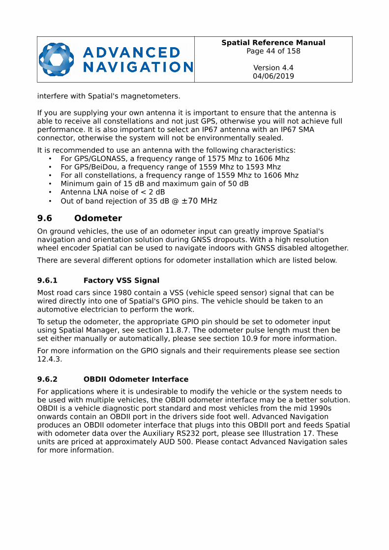
Spatial Reference ManualPage 44 of 158
Version 4.404/06/2019
interfere with Spatial's magnetometers.
If you are supplying your own antenna it is important to ensure that the antenna is able to receive all constellations and not just GPS, otherwise you will not achieve full performance. It is also important to select an IP67 antenna with an IP67 SMA connector, otherwise the system will not be environmentally sealed.
It is recommended to use an antenna with the following characteristics:• For GPS/GLONASS, a frequency range of 1575 Mhz to 1606 Mhz• For GPS/BeiDou, a frequency range of 1559 Mhz to 1593 Mhz• For all constellations, a frequency range of 1559 Mhz to 1606 Mhz• Minimum gain of 15 dB and maximum gain of 50 dB• Antenna LNA noise of < 2 dB• Out of band rejection of 35 dB @ ±70 MHz
9.6 Odometer
On ground vehicles, the use of an odometer input can greatly improve Spatial's navigation and orientation solution during GNSS dropouts. With a high resolution wheel encoder Spatial can be used to navigate indoors with GNSS disabled altogether.
There are several different options for odometer installation which are listed below.
9.6.1 Factory VSS Signal
Most road cars since 1980 contain a VSS (vehicle speed sensor) signal that can be wired directly into one of Spatial's GPIO pins. The vehicle should be taken to an automotive electrician to perform the work.
To setup the odometer, the appropriate GPIO pin should be set to odometer input using Spatial Manager, see section 11.8.7. The odometer pulse length must then be set either manually or automatically, please see section 10.9 for more information.
For more information on the GPIO signals and their requirements please see section12.4.3.
9.6.2 OBDII Odometer Interface
For applications where it is undesirable to modify the vehicle or the system needs to be used with multiple vehicles, the OBDII odometer interface may be a better solution.OBDII is a vehicle diagnostic port standard and most vehicles from the mid 1990s onwards contain an OBDII port in the drivers side foot well. Advanced Navigation produces an OBDII odometer interface that plugs into this OBDII port and feeds Spatialwith odometer data over the Auxiliary RS232 port, please see Illustration 17. These units are priced at approximately AUD 500. Please contact Advanced Navigation sales for more information.

Spatial Reference ManualPage 45 of 158
Version 4.404/06/2019
Illustration 17: Advanced Navigation OBDII Odometer
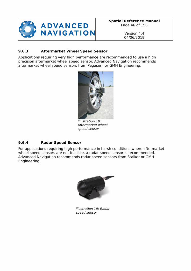
Spatial Reference ManualPage 46 of 158
Version 4.404/06/2019
9.6.3 Aftermarket Wheel Speed Sensor
Applications requiring very high performance are recommended to use a high precision aftermarket wheel speed sensor. Advanced Navigation recommends aftermarket wheel speed sensors from Pegasem or GMH Engineering.
9.6.4 Radar Speed Sensor
For applications requiring high performance in harsh conditions where aftermarket wheel speed sensors are not feasible, a radar speed sensor is recommended. Advanced Navigation recommends radar speed sensors from Stalker or GMH Engineering.
Illustration 18: Aftermarket wheel speed sensor
Illustration 19: Radar speed sensor

Spatial Reference ManualPage 47 of 158
Version 4.404/06/2019
9.7 Magnetics
Spatial contains magnetometers which it uses to measure the Earth's magnetic field inorder to determine its heading. The principle is the same as that of a compass. When operating Spatial with magnetic heading enabled, sources of magnetic interference can degrade Spatial's solution if not compensated for. There are two types of magneticinterference, these are static and dynamic.
Static magnetic interference is caused by steel and other magnetic materials mountedin the vehicle. Static disturbances are easily compensated for by running a magnetic calibration, see section 10.5. A magnetic calibration should always be run after installation into a vehicle.
Dynamic magnetic interference is generally a much bigger issue. Sources of dynamic magnetic interference include high current wiring, electric motors, servos, solenoids and large masses of steel that don't move with Spatial. Spatial should be mounted as far as possible from these interference sources.
Spatial contains a special algorithm to remove the effects of dynamic magnetic interference. This is able to compensate for most typical interference sources encountered, however certain types of prolonged dynamic interference cannot be compensated for. The best way to check for dynamic magnetic interference is to use the raw sensors view in Spatial Manager and watch the magnetometer outputs whilst the vehicle is operating but stationary, see section 11.7.4. The values should be constant, if the values are fluctuating there is dynamic magnetic interference present.
If dynamic magnetic interference is causing performance problems and there is no way to mount Spatial away from the interference source, the magnetometers should be disabled, see section 10.5.4.
9.8 Vibration
Spatial is able to tolerate a high level of vibration compared to other inertial systems. This is due to a unique gyroscope design and a special filtering algorithm. There is however a limit to the amount of vibration that Spatial can tolerate and large levels of vibration will cause Spatial's accuracy to degrade.
When mounting Spatial to a platform with vibration there are several options. It is recommended to first try mounting Spatial and see whether it can tolerate the vibrations. The raw sensor view in the Spatial Manager software can give you a good idea of how bad the vibrations are, see section 11.7.4. If the vibrations are causing thesensors to go over range you will need to increase the sensors range, see section10.6.
If you are unsure about your vibration level, we recommend emailing a Spatial log file of the vibration to [email protected] for feedback.
If Spatial is unable to tolerate the vibrations there are several options:
1. Try to find a mounting point with less vibration.
2. Spatial can be mounted with 3M foam rubber double sided tape or a small flat piece of rubber.

Spatial Reference ManualPage 48 of 158
Version 4.404/06/2019
3. Spatial can be mounted to a plate which is then mounted to the platform through vibration isolation mounts.

Spatial Reference ManualPage 49 of 158
Version 4.404/06/2019
10 Operation
10.1 Initialisation
There are four different levels of initialisation on Spatial. These are orientation, navigation, heading and time. Upon a cold start (more than 48 hours without power) all four levels will typically initialise within 30 seconds and for a hot start (less than 48 hours without power) all four levels will typically initialise within 2 seconds. The initialisation can be monitored by inspecting the status view in Spatial Manager, see section 11.7.2.
After all four levels of initialisation, Spatial's filter takes several minutes to achieve full accuracy. It is recommended to wait two minutes after initialisation for applications requiring high accuracy.
10.1.1 Orientation Initialisation
Orientation initialisation occurs automatically upon power on and typically completes within several seconds. Once orientation initialisation is complete, the roll, pitch and angular velocity values will be valid.
When Spatial starts up, it assumes that it can be in any orientation. To determine its orientation it uses the accelerometers to detect the gravity vector. Whilst this is occurring, if there are random accelerations present, these can cause an incorrect orientation to be detected. To prevent this, Spatial monitors the accelerometers and gyroscopes and restarts the orientation detection if there are sudden movements. It is however still possible under some circumstances for it to miss minor movements and start with a small orientation error. In this scenario Spatial will progressively correct the orientation error over a period of several seconds.
10.1.2 Navigation Initialisation
Navigation initialisation completes once the system has determined a starting position. The most common method of navigation initialisation is for the system to get a 3D GNSS fix. If the system is hot starting it will remember its position from when it was switched off and use this as the starting position. The other possibility for
Illustration 20: The four initialisation levels
Spatial Reference ManualPage 50 of 158
Version 4.404/06/2019
navigation initialisation is an external position source, see section 12.2 for more information. In a situation where a GNSS fix is not available to initialise navigation, it can be initialised manually by entering a position into the position dialogue in Spatial Manager, see section 11.8.12. Once navigation initialisation is complete, the position, velocity and acceleration values will be valid.
10.1.3 Heading Initialisation
Heading initialisation completes once the system has determined a heading. The conditions required to determine a heading depend upon the heading source being used, see section 10.4. If magnetic heading is enabled as a heading source the heading initialisation should complete within 2 seconds after power on. If magnetic heading is disabled and velocity heading is used as the only heading source, the heading will initialise once the system travels at a speed of over 1.15 metres/second for over 5 seconds with a 3D GNSS fix. If the system is hot starting it will remember itsheading from when it was switched off and use this as the starting heading until another source becomes available.
Until the heading has been initialised, the system will not be able to navigate without a GNSS fix and the roll and pitch values will not be able to reach full accuracy.
10.1.4 Time Initialisation
Time initialisation completes once the system has determined time to an accuracy of less than 1 microsecond. This normally occurs as soon as the GNSS receiver obtains itsfirst fix. It is also possible to provide an external source of time, see section 12.2 for more information on external time sources.
Until the time has initialised the values of Unix time and formatted time that Spatial outputs will not be valid and may change.
10.2 Hot Start
Spatial is the first GNSS/INS on the market with hot start functionality. This allows Spatial to start inertial navigation within 500 milliseconds and obtain a GNSS fix in as little as 3 seconds. Spatial's hot start is always on and fully automatic.
A next generation backup battery system within Spatial provides the hot start ability for more than 48 hours without power. When Spatial hot starts it assumes that it is in the same state it was when it lost power and begins navigating from that position. Thehot start also provides ephemeris, almanac and time information to the GNSS receiver which allows it to achieve a fix far more quickly than it otherwise would. When the GNSS achieves its first fix, if this position deviates from the hot start position, Spatial will jump to the new position without causing any side effects to the filter.
Whilst Spatial is without power it keeps track of the time accurately to within 1 second so that the time is immediately valid on a hot start.
Spatial's hot start is of particular benefit to vehicle tracking and robotics applications. The primary benefits are immunity and fast recovery from power failure as well as faststartup time.

Spatial Reference ManualPage 51 of 158
Version 4.404/06/2019
10.3 Time
Spatial was designed to provide a highly accurate time reference. When a GNSS fix is available Spatial's time is accurate to within 50 nanoseconds. When a GNSS fix is lost, Spatial's time accuracy typically remains within 10 microseconds over extended time periods. When Spatial hot starts the time accuracy is typically within 1 second immediately on startup and corrected to within 50 nanoseconds as soon as a GNSS fix is achieved. To synchronise with Spatial's high accuracy time, both the packet protocol and a 1PPS line must be used.
10.4 Heading Source
There are three different heading sources available for Spatial. The heading source canbe selected using the filter options dialogue in Spatial Manager, see section 11.8.3. It is possible to use multiple heading sources and this can often provide performance benefits.
10.4.1 Magnetic Heading
This is the default heading source and works well in the majority of cases. When using magnetic heading, calibration is required every time Spatial's installation changes. Thedownside of magnetic heading is that prolonged dynamic magnetic interference sources can cause heading errors.
10.4.2 Velocity Heading
Velocity heading works by deriving heading from the direction of velocity and acceleration. Velocity heading works well with cars, boats, fixed wing aircraft and othervehicles that don't move sideways. Velocity heading does not work with helicopters and other 3D vehicles. The downside of velocity heading is that heading can not be measured until the vehicle moves at a horizontal speed of over 1.15 metres/second with a GNSS fix. The benefits of velocity heading are that it is immune to magnetic interference and no calibration is required when Spatial's installation changes.
10.4.3 External Heading
This can be used if there is some other way to derive heading that is external to Spatial. Examples include dual antenna GNSS systems, north seeking gyroscopes, reference markers and SLAM systems. The heading must be fed into Spatial using theExternal Heading Packet or through the auxiliary RS232.
10.5 Magnetics
Static magnetic interference is resolved through magnetic calibration and dynamic magnetic interference is compensated by a filter algorithm but should be minimised where possible through installation location. Please see section 9.7 for more information on magnetic interference. To compensate for static magnetic interference, magnetic calibration should be performed any time Spatial's installation changes.
Spatial contains a dynamic magnetic compensation filter that is able to mitigate the effects of short term magnetic interference sources while in operation. For example if
Spatial Reference ManualPage 52 of 158
Version 4.404/06/2019
Spatial is installed in a car and the car drives over a large piece of magnetised steel, this will be compensated for. Another example is driving through a tunnel which is builtfrom heavily reinforced concrete. It is important to note that for Spatial's dynamic magnetic compensation filter to operate correctly, Spatial needs to get a GNSS fix at least once every time it is moved more than 50km. Each time Spatial moves more than 50km the new position is stored permanently and allows Spatial to update its world magnetic model values.
There are three types of magnetic calibration available, these are 2D calibration, 3D calibration and automatic calibration. 2D calibration involves one level rotation about the Z axis and is designed for vehicles that cannot easily or safely be turned upside down, such as full size cars, planes and boats. 3D calibration involves rotating throughall orientations and is designed for vehicles that can easily and safely be rotated upside down, such as model size vehicles. 3D calibration offers slightly better performance and is recommended where possible. Automatic magnetic calibration continuously and automatically calibrates for static magnetic interference while the unit is in operation. It is not as accurate as the 2D or 3D calibration, however it is very convenient for applications where Spatial needs to just work without user intervention.
Please note that if Spatial is going to be used in a vehicle, the calibration should be performed while Spatial is mounted in and fixed to that vehicle. This means that the whole vehicle must be moved to perform the calibration. The calibration needs to be performed in an area away from sources of magnetic interference. For example if Spatial is installed in a car, the calibration should not involve driving over steel drains or reinforced concrete etc. If Spatial is being calibrated to operate standalone, the calibration should not be done on a desk with a steel frame.
10.5.1 2D Magnetic Calibration
The following procedure should be used to perform a 2D magnetic calibration.
10.5.1.1 Using the Spatial Manager Software
1. The unit should be powered on while the vehicle is in a level orientation and kept stationary.
2. After power on wait 5 minutes for the temperature and filter to stabilise.
3. Open Spatial Manager and connect to the device. Ensure that the device has a GNSS fix before proceeding.
4. In the Tools menu, open Magnetic Calibration. Click the 2D Calibration button. See section 11.9.2.
5. Whilst keeping as level as possible, rotate the vehicle in either direction throughone and a quarter full rotations. In a car this can be achieved by driving in one and a quarter circles.
6. Check the status in the Magnetic Calibration window to ensure that the calibration completed successfully. If not successful click Cancel, wait 2 minutes and repeat from step 4. Do not press the save button in the lower half of the dialogue, this will over write the new calibration values. The calibration values are automatically saved internally.
Spatial Reference ManualPage 53 of 158
Version 4.404/06/2019
10.5.1.2 Using the Packet Protocol
1. The unit should be powered on while the vehicle is in a level orientation and kept stationary.
2. After power on wait 5 minutes for the temperature and filter to stabilise.
3. Ensure that the device has a GNSS fix before proceeding
4. Send the Magnetic Calibration Configuration Packet with the action Start 2D Magnetic Calibration.
5. Whilst keeping as level as possible, rotate the vehicle in either direction throughone and a quarter full rotations. In a car this can be achieved by driving in one and a quarter circles.
6. Read the Magnetic Calibration Status Packet to ensure that the calibration completed successfully. If not successful, send the Magnetic Calibration Configuration Packet with the action Cancel, wait 2 minutes and repeat from step 4.
Spatial Reference ManualPage 54 of 158
Version 4.404/06/2019
10.5.2 3D Magnetic Calibration
The following procedure should be used to perform a 3D magnetic calibration.
10.5.2.1 Using the Spatial Manager Software
1. The unit should be powered on and the vehicle kept stationary.
2. After power on wait 5 minutes for the temperature and filter to stabilise.
3. Open Spatial Manager and connect to the device. Ensure that the device has a GNSS fix before proceeding.
4. In the Tools menu, open Magnetic Calibration. Click the 3D Calibration button. See section 11.9.2. The following steps 5, 6 and 7 can be performed in any order.
5. Slowly rotate the vehicle twice around the X axis (roll).
6. Slowly rotate the vehicle twice around the Y axis (pitch).
7. Slowly rotate the vehicle twice around the Z axis (heading).
8. Check the status in the Magnetic Calibration window to ensure that the calibration completed successfully. If not successful click Cancel, wait 2 minutes and repeat from step 4. Do not press the save button in the lower half of the dialogue, this will over write the new calibration values. The calibration values are automatically saved internally.
10.5.2.2 Using the Packet Protocol
1. The unit should be powered on and the vehicle kept stationary.
2. After power on wait 5 minutes for the temperature and filter to stabilise.
3. Ensure that the device has a GNSS fix before proceeding
4. Send the Magnetic Calibration Configuration Packet with the action Start 3D Magnetic Calibration. The following steps 5, 6 and 7 can be performed in any order.
5. Slowly rotate the vehicle twice around the X axis (roll).
6. Slowly rotate the vehicle twice around the Y axis (pitch).
7. Slowly rotate the vehicle twice around the Z axis (heading)
8. Read the Magnetic Calibration Status Packet to ensure that the calibration completed successfully. If not successful, send the Magnetic Calibration Configuration Packet with the action Cancel, wait 2 minutes and repeat from step 4.
10.5.3 Automatic Magnetic Calibration
Automatic magnetic calibration is an algorithm that continuously and automatically calibrates for static magnetic interference. Automatic magnetic calibration is enabled by default and it is recommended to keep it enabled for all vehicle types. When used
Spatial Reference ManualPage 55 of 158
Version 4.404/06/2019
on top of a 2D or 3D calibration it can give the best results from magnetic heading. Every time Spatial is powered on in a cold start (48 hours without power) the automatic calibration is reset. The automatic magnetic calibration starts operating when Spatial is travelling at a speed over 5 m/s with a GNSS fix and velocity heading turned on. Automatic magnetic calibration is not as accurate as 2D or 3D calibration, however it is sufficient for most vehicles and allows Spatial to be installed into vehiclesand operated without user intervention. Automatic magnetic calibration can be turned off using the filter options dialogue in Spatial Manager, see section 11.8.3.
10.5.4 Disabling Magnetometers
In situations where there is very strong dynamic magnetic disturbances present, it is recommended to disable the magnetometers. When the magnetometers are disabled a secondary heading source is required otherwise may become inaccurate. Velocity heading is the recommended source. Please see section 10.4 for information on heading sources. The magnetometers can be disabled using the filter options dialogue in Spatial Manager, see section 11.8.3.
10.6 Sensors Range
Spatial supports dynamic ranging on its sensors. Each of the three sensors have three different range levels. At lower ranges the sensor performance is better, but at higher ranges Spatial can be used in more extreme dynamics. It is important to choose a range that your application won't exceed.
Sensor over range events can be detected through the Filter Status. In Spatial manager the status indicator will go orange indicating that a sensor has gone over range. When a sensor goes over range this causes the filter solution to become inaccurate and in some cases it can cause the filter to reset.
By default Spatial comes configured in the lowest sensor ranges. In this configuration it is possible to send the gyroscopes over range by quickly rotating the unit in your hand. It is recommended to watch what happens in Spatial Manager when you do this.
The sensor ranges can be set through the sensor ranges dialogue in the configuration menu in Spatial Manager, see section 11.8.2.
10.7 Data Anti Aliasing
Internally Spatial's filters update at 1000 Hz. When Spatial outputs data, most applications require the data at a much lower rate (typically < 100 Hz). This causes a problem for time based data such as velocities and accelerations where aliasing will occur at the lower rate. To prevent this problem, if the output rate is lower than 1000 Hz, Spatial will low pass filter the values of the time dependent data between packets to prevent aliasing. This is only the case when a packet is set up to output at a certain rate. If the packet is simply requested no anti aliasing will occur. Additionally there is no anti aliasing for non time dependent fields such as position.
10.8 Vehicle Profiles
Spatial supports a number of different vehicle profiles. These vehicle profiles impose

Spatial Reference ManualPage 56 of 158
Version 4.404/06/2019
constraints upon the filter that can increase performance. If your application matches one of the available vehicle profiles, it is recommended to select it for use in the filter options dialogue in Spatial Manager, see section 11.8.3. For a list of the different vehicle profiles please see section 13.10.6.1. Please note that if the wrong vehicle profile is selected it can cause a significant decrease in performance.
Spatial Reference ManualPage 57 of 158
Version 4.404/06/2019
10.9 Odometer Pulse Length
For Spatial to use a wheel speed sensor or odometer input, it must know the pulse length of the signal. The pulse length is the distance in metres between low to high transitions of the signal. The odometer pulse length can either be entered manually or automatically calibrated by Spatial. To enter the pulse length manually, please use theodometer configuration dialogue in Spatial Manager, see section 11.8.8. To automatically calibrate the odometer pulse length please use the procedure listed below in section 10.9.1. By default the odometer will automatically calibrate itself.
10.9.1 Odometer Automatic Pulse Length Calibration Procedure
1. Ensure that the signal is connected correctly and that the GPIO pin is configuredas an odometer input using the GPIO configuration dialogue in Spatial Manager, see section 11.8.7.
2. Open Spatial Manager, connect to Spatial and open the odometer configuration dialogue, see section 11.8.8. In the odometer configuration dialogue tick the automatic pulse length calibration check box and press the save button.
3. Wait until Spatial has a continuous GNSS fix and then drive 1000 metres over flat terrain with as little turning as possible.
4. If Spatial loses a GNSS fix for more than several seconds during the calibration, the distance travelled will be reset. The distance travelled can be checked in theodometer configuration dialogue to ensure that it has passed 1000m.
5. Once 1000 metres has been driven, check that the automatic pulse length check box becomes un-ticked and the pulse length value has changed. This indicates a successfully completed calibration.
10.10 Reversing Detection
Reversing detection is an algorithm that can detect when the vehicle is travelling in reverse. Knowledge of reverse motion is important when using velocity heading or odometer input to provide correct results. If Spatial is fitted to a vehicle that does not reverse or doesn't use velocity heading or odometer, this function should be disabled. For all other applications it is best to leave it enabled. Reversing detection is enabled by default and it can be disabled using the filter configuration window in Spatial Manager, see section 11.8.3.
10.11 Motion Analysis
Motion analysis is an artificial intelligence algorithm that associates patterns in high frequency inertial data with the speed of the vehicle. After power on it takes some time to match patterns with speed before it will become active. Motion analysis only activates when dead reckoning and is most effective when the vehicle is moving slowly or stationary. Motion analysis does not work in all situations and its primary benefit is in ground vehicles. It should be enabled in any car application. When active it can be recognised by 2Hz steps in velocity data. Motion analysis is disabled by default and can be enabled using the filter configuration window in Spatial Manager,
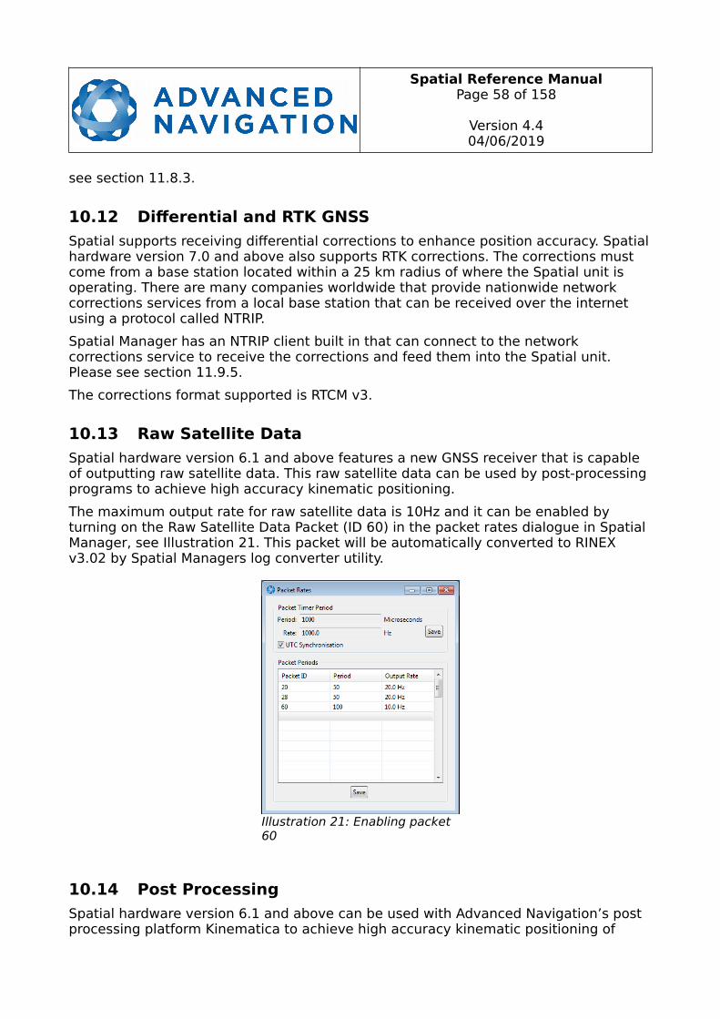
Spatial Reference ManualPage 58 of 158
Version 4.404/06/2019
see section 11.8.3.
10.12 Differential and RTK GNSS
Spatial supports receiving differential corrections to enhance position accuracy. Spatialhardware version 7.0 and above also supports RTK corrections. The corrections must come from a base station located within a 25 km radius of where the Spatial unit is operating. There are many companies worldwide that provide nationwide network corrections services from a local base station that can be received over the internet using a protocol called NTRIP.
Spatial Manager has an NTRIP client built in that can connect to the network corrections service to receive the corrections and feed them into the Spatial unit. Please see section 11.9.5.
The corrections format supported is RTCM v3.
10.13 Raw Satellite Data
Spatial hardware version 6.1 and above features a new GNSS receiver that is capable of outputting raw satellite data. This raw satellite data can be used by post-processing programs to achieve high accuracy kinematic positioning.
The maximum output rate for raw satellite data is 10Hz and it can be enabled by turning on the Raw Satellite Data Packet (ID 60) in the packet rates dialogue in Spatial Manager, see Illustration 21. This packet will be automatically converted to RINEX v3.02 by Spatial Managers log converter utility.
10.14 Post Processing
Spatial hardware version 6.1 and above can be used with Advanced Navigation’s post processing platform Kinematica to achieve high accuracy kinematic positioning of
Illustration 21: Enabling packet 60
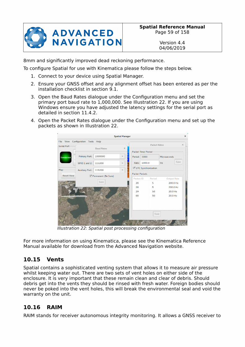
Spatial Reference ManualPage 59 of 158
Version 4.404/06/2019
8mm and significantly improved dead reckoning performance.
To configure Spatial for use with Kinematica please follow the steps below.
1. Connect to your device using Spatial Manager.
2. Ensure your GNSS offset and any alignment offset has been entered as per the installation checklist in section 9.1.
3. Open the Baud Rates dialogue under the Configuration menu and set the primary port baud rate to 1,000,000. See Illustration 22. If you are using Windows ensure you have adjusted the latency settings for the serial port as detailed in section 11.4.2.
4. Open the Packet Rates dialogue under the Configuration menu and set up the packets as shown in Illustration 22.
For more information on using Kinematica, please see the Kinematica Reference Manual available for download from the Advanced Navigation website.
10.15 Vents
Spatial contains a sophisticated venting system that allows it to measure air pressure whilst keeping water out. There are two sets of vent holes on either side of the enclosure. It is very important that these remain clean and clear of debris. Should debris get into the vents they should be rinsed with fresh water. Foreign bodies should never be poked into the vent holes, this will break the environmental seal and void thewarranty on the unit.
10.16 RAIM
RAIM stands for receiver autonomous integrity monitoring. It allows a GNSS receiver to
Illustration 22: Spatial post processing configuration
Spatial Reference ManualPage 60 of 158
Version 4.404/06/2019
detect and exclude both faulty and fraudulent satellite signals. Spatial's internal GNSS is equipped with RAIM and it is enabled by default.
10.17 Heave
Spatial can provide vertical heave position at four different points on a ship. Spatial's heave filter is always on and fully automatic. After power on, Spatial requires approximately 5 minutes for its heave filter to converge upon an accurate solution. Heave works without a GNSS fix, however best heave performance is achieved when Spatial has a GNSS fix.
By default Spatial provides heave from the point at which the Spatial unit is mounted, however it can provide heave at four different offset points on the ship. To set the heave offsets, either use the heave configuration dialogue in Spatial Manager, see section 11.8.10.
10.18 Environmental Exposure
Whilst Spatial is environmentally protected, there are clearly defined limits to this protection that must be adhered to for reliable operation.
Spatial is only protected when its connector is mated and an IP67 SMA GNSS antenna is attached to it. When either of these two connections are not finger tightly closed theunit offers no environmental protection.
Spanners or tools should never be used to tighten the connectors. They should only ever be finger tight.
10.18.1 Temperature
Spatial should not be subjected to temperatures outside of its operating range. If the temperature rises above 90 degrees Celsius, Spatial will automatically shut off power to its sensors and GNSS in an attempt to prevent damage, this will also send the filtersinto reset. Subjecting Spatial to temperature's outside of the storage range can effect the factory sensor calibration which will cause a permanent performance degradation.
10.18.2 Water
Spatial is water-proof to the IP67 standard which means that it can be submersed in water to a depth of up to 1 metre only. Submersion to depths beyond 1 metre can cause water entry and destruction of the internal electronics.
10.18.3 Salt
Spatial is made from marine grade aluminium which gives it reasonably good salt water corrosion resistance. However Spatial cannot tolerate extended periods of time in salt water environments. After any contact with salt water environments, Spatial should be thoroughly rinsed with fresh water.
10.18.4 Dirt and Dust
Spatial is completely sealed against dirt and dust entry. It is important to note that this
Spatial Reference ManualPage 61 of 158
Version 4.404/06/2019
is only the case when the connectors are mated. When un-mating the connectors if the Spatial unit is dirty or dusty, the dirt should be rinsed off with fresh water first and then dried off. This is to prevent dirt or dust entering the connectors which can cause them to fail.
10.18.5 PH Level
Environments with a high or low PH level can cause the Spatial enclosure to corrode. IfSpatial comes into contact with these environments it should be rinsed in fresh water as soon as possible. It is not recommended to operate Spatial in non neutral PH environments.
10.18.6 Shocks
Spatial can tolerate shocks to 2000g, however continuous shocks of this severity are likely to cause premature failure. Shocks above 2000g can effect the factory sensor calibration and degrade performance. Normally shocks to Spatial when mounted in a vehicle are fine. Even a high speed car crash is likely to reach a peak of only 50g. Shocks directly to Spatial's enclosure can more easily go over the limit however so care should be taken when handling the unit prior to mounting.

Spatial Reference ManualPage 62 of 158
Version 4.404/06/2019
11 Spatial ManagerSpatial Manager is a software tool provided by Advanced Navigation for logging, testing, display and configuration of Spatial. It is designed to be simple and easy to use.
Illustration 23: Screenshot of Spatial Manager
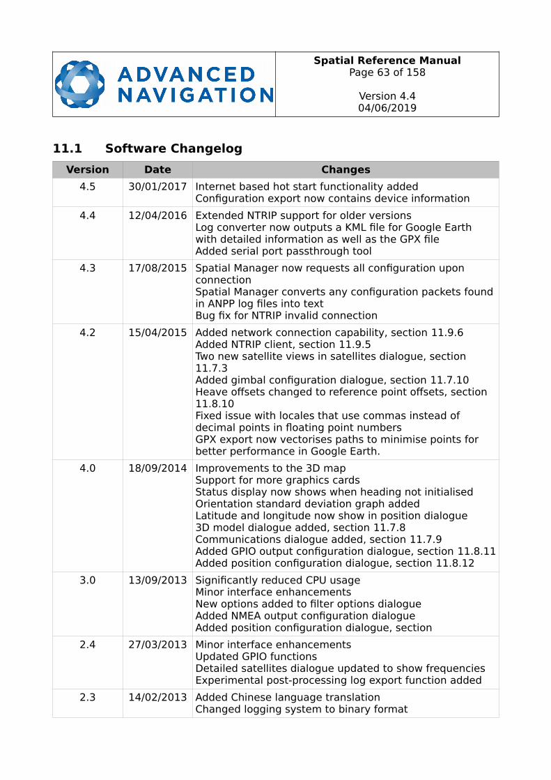
Spatial Reference ManualPage 63 of 158
Version 4.404/06/2019
11.1 Software Changelog
Version Date Changes
4.5 30/01/2017 Internet based hot start functionality addedConfiguration export now contains device information
4.4 12/04/2016 Extended NTRIP support for older versionsLog converter now outputs a KML file for Google Earth with detailed information as well as the GPX fileAdded serial port passthrough tool
4.3 17/08/2015 Spatial Manager now requests all configuration upon connectionSpatial Manager converts any configuration packets foundin ANPP log files into textBug fix for NTRIP invalid connection
4.2 15/04/2015 Added network connection capability, section 11.9.6Added NTRIP client, section 11.9.5Two new satellite views in satellites dialogue, section11.7.3Added gimbal configuration dialogue, section 11.7.10Heave offsets changed to reference point offsets, section11.8.10Fixed issue with locales that use commas instead of decimal points in floating point numbersGPX export now vectorises paths to minimise points for better performance in Google Earth.
4.0 18/09/2014 Improvements to the 3D mapSupport for more graphics cardsStatus display now shows when heading not initialisedOrientation standard deviation graph addedLatitude and longitude now show in position dialogue3D model dialogue added, section 11.7.8Communications dialogue added, section 11.7.9Added GPIO output configuration dialogue, section 11.8.11Added position configuration dialogue, section 11.8.12
3.0 13/09/2013 Significantly reduced CPU usageMinor interface enhancementsNew options added to filter options dialogueAdded NMEA output configuration dialogueAdded position configuration dialogue, section
2.4 27/03/2013 Minor interface enhancementsUpdated GPIO functionsDetailed satellites dialogue updated to show frequenciesExperimental post-processing log export function added
2.3 14/02/2013 Added Chinese language translationChanged logging system to binary format
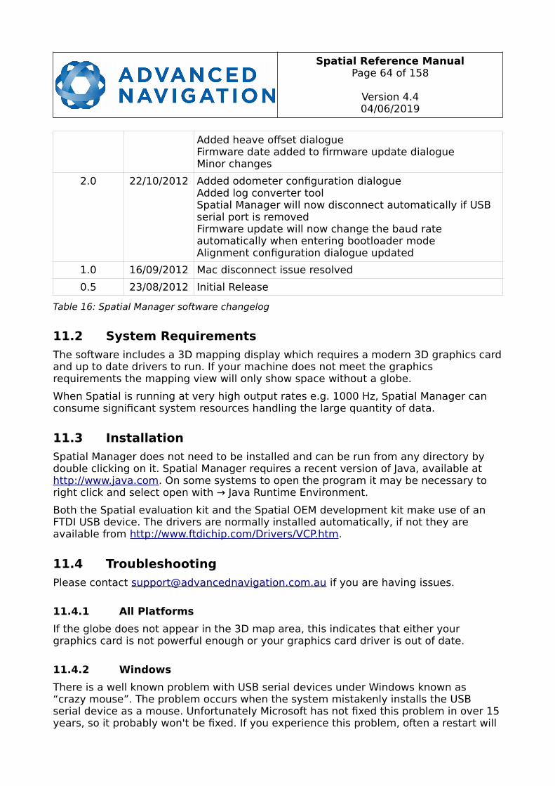
Spatial Reference ManualPage 64 of 158
Version 4.404/06/2019
Added heave offset dialogueFirmware date added to firmware update dialogueMinor changes
2.0 22/10/2012 Added odometer configuration dialogueAdded log converter toolSpatial Manager will now disconnect automatically if USB serial port is removedFirmware update will now change the baud rate automatically when entering bootloader modeAlignment configuration dialogue updated
1.0 16/09/2012 Mac disconnect issue resolved
0.5 23/08/2012 Initial Release
Table 16: Spatial Manager software changelog
11.2 System Requirements
The software includes a 3D mapping display which requires a modern 3D graphics cardand up to date drivers to run. If your machine does not meet the graphics requirements the mapping view will only show space without a globe.
When Spatial is running at very high output rates e.g. 1000 Hz, Spatial Manager can consume significant system resources handling the large quantity of data.
11.3 Installation
Spatial Manager does not need to be installed and can be run from any directory by double clicking on it. Spatial Manager requires a recent version of Java, available at http://www.java.com. On some systems to open the program it may be necessary to right click and select open with → Java Runtime Environment.
Both the Spatial evaluation kit and the Spatial OEM development kit make use of an FTDI USB device. The drivers are normally installed automatically, if not they are available from http://www.ftdichip.com/Drivers/VCP.htm.
11.4 Troubleshooting
Please contact [email protected] if you are having issues.
11.4.1 All Platforms
If the globe does not appear in the 3D map area, this indicates that either your graphics card is not powerful enough or your graphics card driver is out of date.
11.4.2 Windows
There is a well known problem with USB serial devices under Windows known as “crazy mouse”. The problem occurs when the system mistakenly installs the USB serial device as a mouse. Unfortunately Microsoft has not fixed this problem in over 15years, so it probably won't be fixed. If you experience this problem, often a restart will
Spatial Reference ManualPage 65 of 158
Version 4.404/06/2019
resolve it. Otherwise there is a tool available at http://www.stentec.com/anonftp/pub/wingps/pnpblockersetup.exe that can fix the issue.
If the serial port does not show up when you plug in your Spatial USB device, you may need to install the drivers from http://www.ftdichip.com/Drivers/VCP.htm.
If you experience a blue screen of death whilst using Spatial Manager, this is typically a problem associated with older FTDI drivers. To resolve the problem, install the latest drivers from http://www.ftdichip.com/Drivers/VCP.htm.
When operating Spatial at a very high data rate, data can be lost due to the latency of the FTDI driver. To resolve this problem the latency of the driver should be reduced by going to control panel → system → device manager → ports and right click on the USB serial port, then click properties. In the properties window click the port settings tab and then the advanced button. You then need to change the latency timer setting to 1ms. Please see the screenshot in Illustration 24.
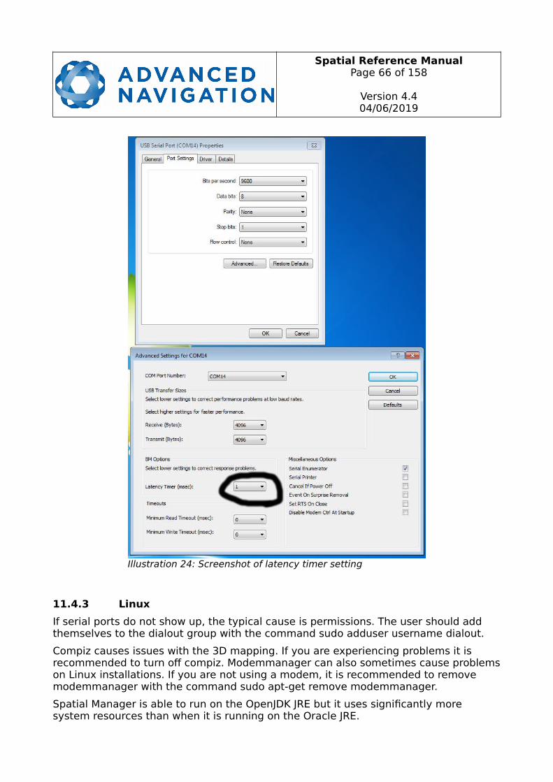
Spatial Reference ManualPage 66 of 158
Version 4.404/06/2019
11.4.3 Linux
If serial ports do not show up, the typical cause is permissions. The user should add themselves to the dialout group with the command sudo adduser username dialout.
Compiz causes issues with the 3D mapping. If you are experiencing problems it is recommended to turn off compiz. Modemmanager can also sometimes cause problemson Linux installations. If you are not using a modem, it is recommended to remove modemmanager with the command sudo apt-get remove modemmanager.
Spatial Manager is able to run on the OpenJDK JRE but it uses significantly more system resources than when it is running on the Oracle JRE.
Illustration 24: Screenshot of latency timer setting
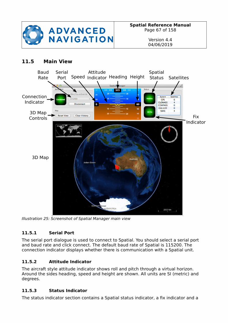
Spatial Reference ManualPage 67 of 158
Version 4.404/06/2019
11.5 Main View
11.5.1 Serial Port
The serial port dialogue is used to connect to Spatial. You should select a serial port and baud rate and click connect. The default baud rate of Spatial is 115200. The connection indicator displays whether there is communication with a Spatial unit.
11.5.2 Attitude Indicator
The aircraft style attitude indicator shows roll and pitch through a virtual horizon. Around the sides heading, speed and height are shown. All units are SI (metric) and degrees.
11.5.3 Status Indicator
The status indicator section contains a Spatial status indicator, a fix indicator and a
Illustration 25: Screenshot of Spatial Manager main view
Spatial Reference ManualPage 68 of 158
Version 4.404/06/2019
satellites table.
11.5.3.1 Spatial Status Indicator
This indicator shows any problems with Spatial. Before a GNSS fix is achieved it will show the status “Filter not initialised”. Once the filter has initialised it should show “Healthy”. Clicking on the indicator will show the detailed status flags.
11.5.3.2 Fix Indicator
This shows the status of the GNSS fix. Under normal operating conditions it should show either “3D Fix” or “SBAS Fix”. When satellite visibility is poor it may show either “2D Fix” or “No Fix”.
11.5.3.3 Satellites Table
The satellites table shows the number of active satellites being used in the current GNSS solution. More detailed information can be found in the satellites view, see section 11.7.3.
11.5.4 3D Map
The 3D map shows Spatial's position on the Earth as well as a red trail of position history. When the filter initialises the map will automatically reset the view to Spatial's location. To move the camera click and drag on the map. To zoom in and out use the scroll wheel. To change the camera view angle right click and drag or shift click and drag.
11.5.5 3D Map Controls
11.5.5.1 Reset View
This resets the map view to Spatial's current position.
11.5.5.2 Clear History
This clears the current position history, this is the red trail shown on the map.
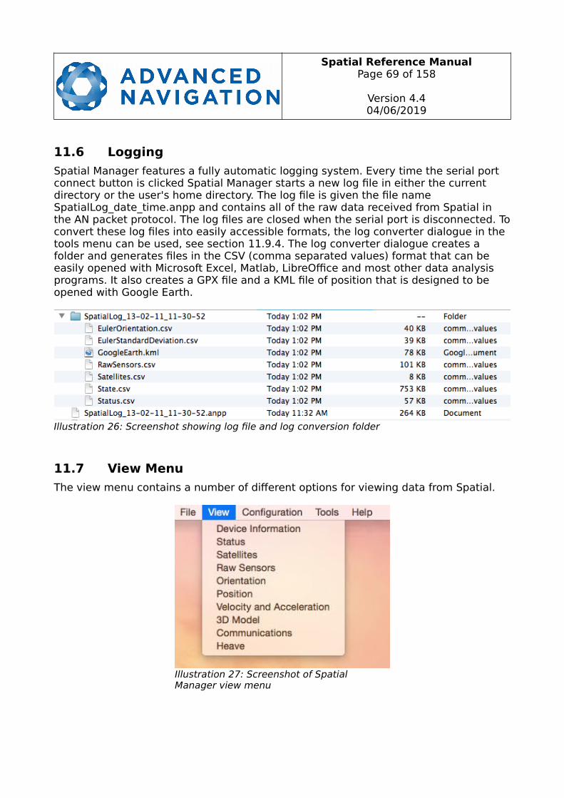
Spatial Reference ManualPage 69 of 158
Version 4.404/06/2019
11.6 Logging
Spatial Manager features a fully automatic logging system. Every time the serial port connect button is clicked Spatial Manager starts a new log file in either the current directory or the user's home directory. The log file is given the file name SpatialLog_date_time.anpp and contains all of the raw data received from Spatial in the AN packet protocol. The log files are closed when the serial port is disconnected. Toconvert these log files into easily accessible formats, the log converter dialogue in the tools menu can be used, see section 11.9.4. The log converter dialogue creates a folder and generates files in the CSV (comma separated values) format that can be easily opened with Microsoft Excel, Matlab, LibreOffice and most other data analysis programs. It also creates a GPX file and a KML file of position that is designed to be opened with Google Earth.
11.7 View Menu
The view menu contains a number of different options for viewing data from Spatial.
Illustration 26: Screenshot showing log file and log conversion folder
Illustration 27: Screenshot of Spatial Manager view menu

Spatial Reference ManualPage 70 of 158
Version 4.404/06/2019
11.7.1 Device Information
Device information is useful during technical support and for tracking your serial number, firmware and hardware version.
11.7.2 Status
Status shows Spatial's complete status as contained in the system state packet detailed in section 13.9.1.1.
Illustration 28: Screenshot of Spatial Managerdevice information dialogue
Illustration 29: Screenshot of Spatial Manager status dialogue
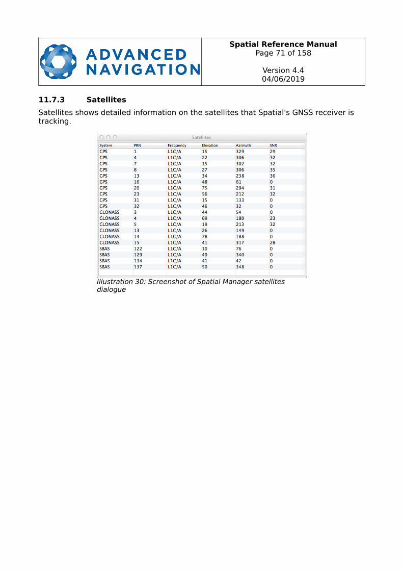
Spatial Reference ManualPage 71 of 158
Version 4.404/06/2019
11.7.3 Satellites
Satellites shows detailed information on the satellites that Spatial's GNSS receiver is tracking.
Illustration 30: Screenshot of Spatial Manager satellites dialogue

Spatial Reference ManualPage 72 of 158
Version 4.404/06/2019
11.7.4 Raw Sensors
Raw sensors shows the temperature calibrated raw sensor values.
Illustration 31: Screenshot of Spatial Manager raw sensors dialogue
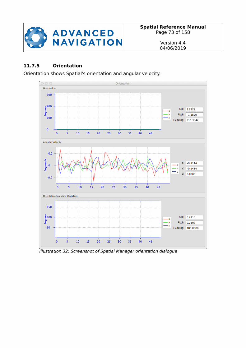
Spatial Reference ManualPage 73 of 158
Version 4.404/06/2019
11.7.5 Orientation
Orientation shows Spatial's orientation and angular velocity.
Illustration 32: Screenshot of Spatial Manager orientation dialogue
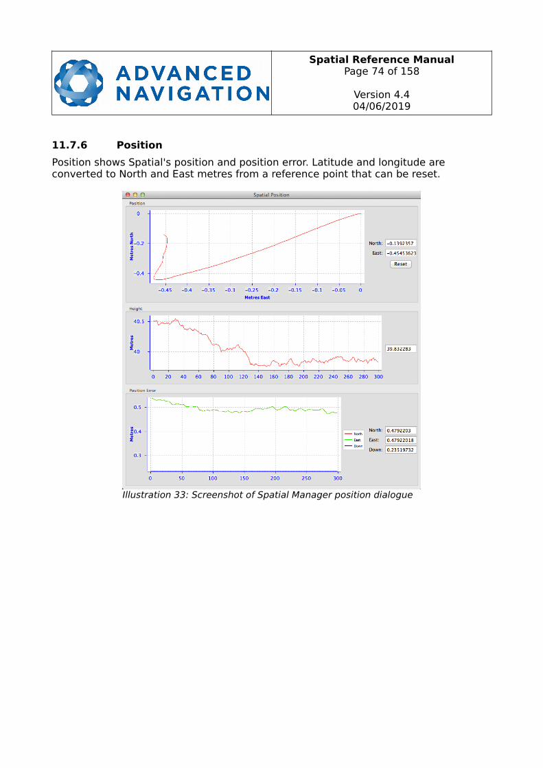
Spatial Reference ManualPage 74 of 158
Version 4.404/06/2019
11.7.6 Position
Position shows Spatial's position and position error. Latitude and longitude are converted to North and East metres from a reference point that can be reset.
Illustration 33: Screenshot of Spatial Manager position dialogue

Spatial Reference ManualPage 75 of 158
Version 4.404/06/2019
11.7.7 Velocity and Acceleration
Velocity and Acceleration shows Spatial's velocity, acceleration and g-force.
Illustration 34: Screenshot of Spatial Manager velocity and acceleration dialogue
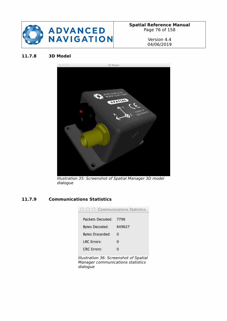
Spatial Reference ManualPage 76 of 158
Version 4.404/06/2019
11.7.8 3D Model
11.7.9 Communications Statistics
Illustration 35: Screenshot of Spatial Manager 3D model dialogue
Illustration 36: Screenshot of SpatialManager communications statistics dialogue
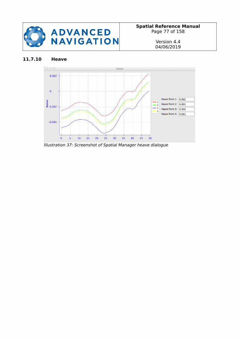
Spatial Reference ManualPage 77 of 158
Version 4.404/06/2019
11.7.10 Heave
Illustration 37: Screenshot of Spatial Manager heave dialogue
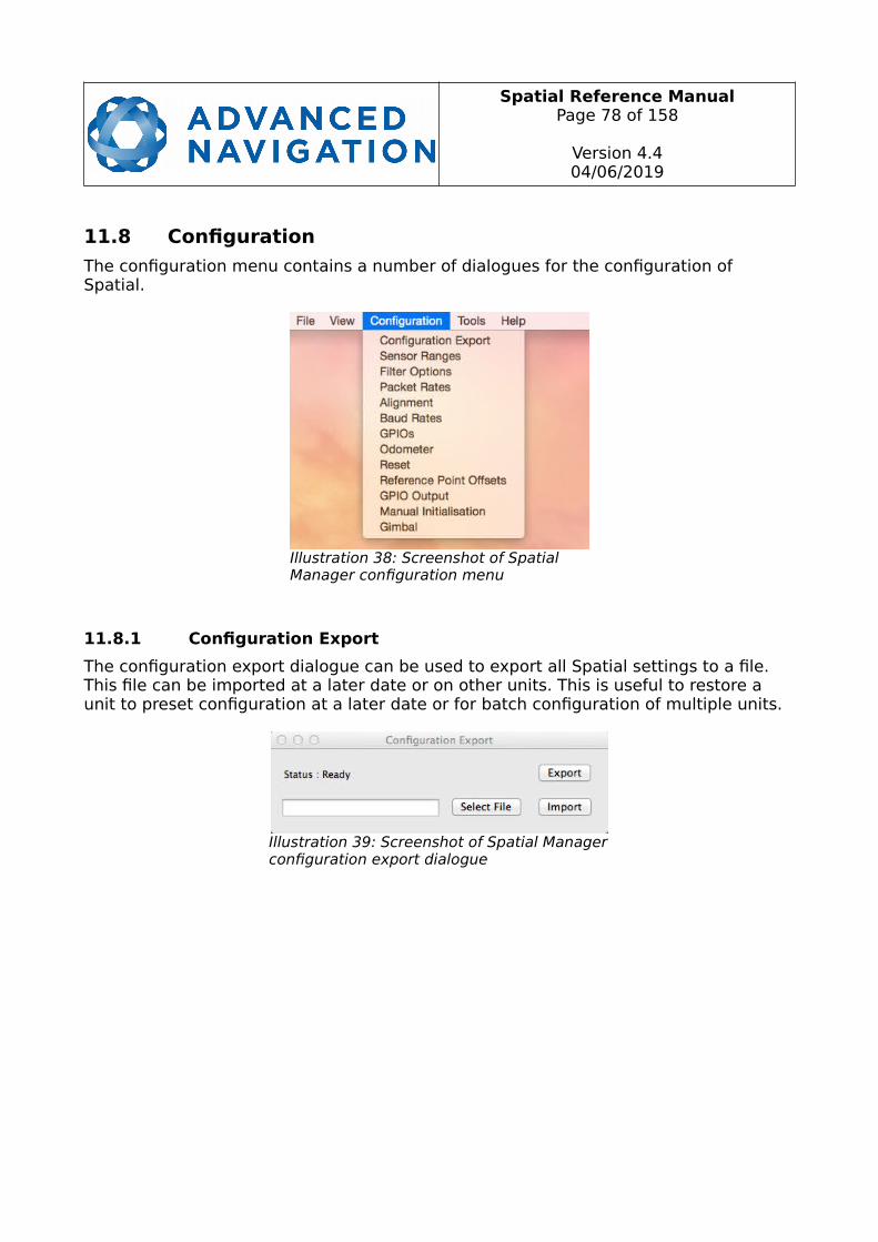
Spatial Reference ManualPage 78 of 158
Version 4.404/06/2019
11.8 Configuration
The configuration menu contains a number of dialogues for the configuration of Spatial.
11.8.1 Configuration Export
The configuration export dialogue can be used to export all Spatial settings to a file. This file can be imported at a later date or on other units. This is useful to restore a unit to preset configuration at a later date or for batch configuration of multiple units.
Illustration 38: Screenshot of Spatial Manager configuration menu
Illustration 39: Screenshot of Spatial Managerconfiguration export dialogue
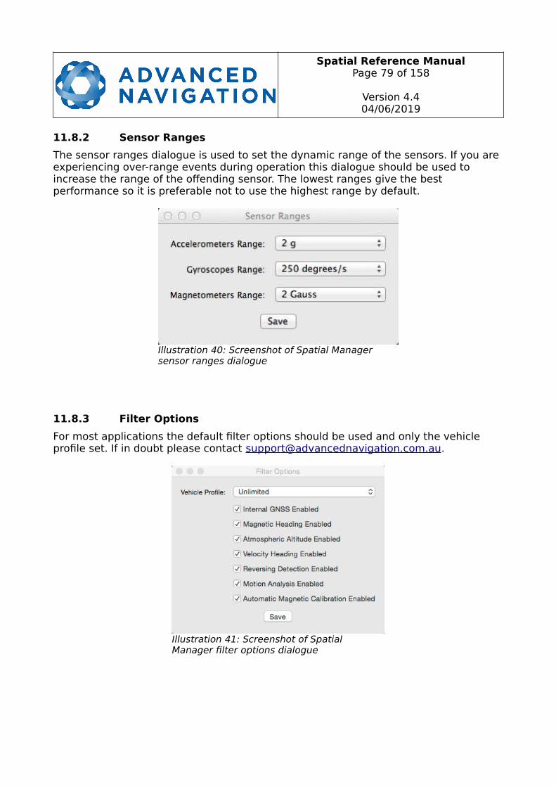
Spatial Reference ManualPage 79 of 158
Version 4.404/06/2019
11.8.2 Sensor Ranges
The sensor ranges dialogue is used to set the dynamic range of the sensors. If you are experiencing over-range events during operation this dialogue should be used to increase the range of the offending sensor. The lowest ranges give the best performance so it is preferable not to use the highest range by default.
11.8.3 Filter Options
For most applications the default filter options should be used and only the vehicle profile set. If in doubt please contact [email protected].
Illustration 40: Screenshot of Spatial Manager sensor ranges dialogue
Illustration 41: Screenshot of Spatial Manager filter options dialogue
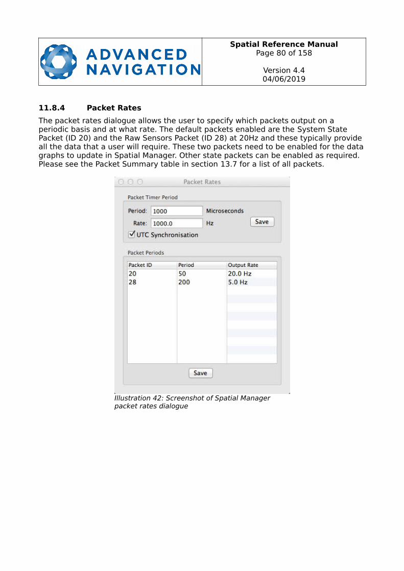
Spatial Reference ManualPage 80 of 158
Version 4.404/06/2019
11.8.4 Packet Rates
The packet rates dialogue allows the user to specify which packets output on a periodic basis and at what rate. The default packets enabled are the System State Packet (ID 20) and the Raw Sensors Packet (ID 28) at 20Hz and these typically provide all the data that a user will require. These two packets need to be enabled for the datagraphs to update in Spatial Manager. Other state packets can be enabled as required. Please see the Packet Summary table in section 13.7 for a list of all packets.
Illustration 42: Screenshot of Spatial Manager packet rates dialogue
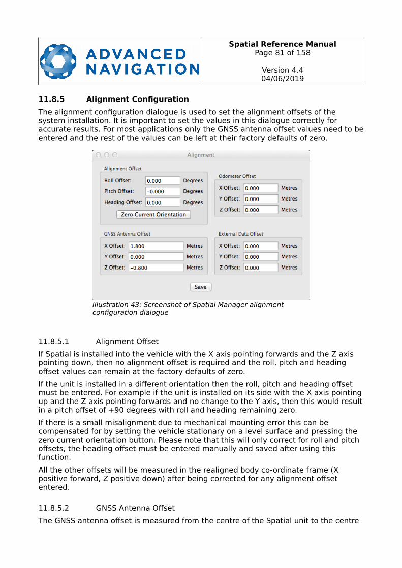
Spatial Reference ManualPage 81 of 158
Version 4.404/06/2019
11.8.5 Alignment Configuration
The alignment configuration dialogue is used to set the alignment offsets of the system installation. It is important to set the values in this dialogue correctly for accurate results. For most applications only the GNSS antenna offset values need to beentered and the rest of the values can be left at their factory defaults of zero.
11.8.5.1 Alignment Offset
If Spatial is installed into the vehicle with the X axis pointing forwards and the Z axis pointing down, then no alignment offset is required and the roll, pitch and heading offset values can remain at the factory defaults of zero.
If the unit is installed in a different orientation then the roll, pitch and heading offset must be entered. For example if the unit is installed on its side with the X axis pointingup and the Z axis pointing forwards and no change to the Y axis, then this would resultin a pitch offset of +90 degrees with roll and heading remaining zero.
If there is a small misalignment due to mechanical mounting error this can be compensated for by setting the vehicle stationary on a level surface and pressing the zero current orientation button. Please note that this will only correct for roll and pitch offsets, the heading offset must be entered manually and saved after using this function.
All the other offsets will be measured in the realigned body co-ordinate frame (X positive forward, Z positive down) after being corrected for any alignment offset entered.
11.8.5.2 GNSS Antenna Offset
The GNSS antenna offset is measured from the centre of the Spatial unit to the centre
Illustration 43: Screenshot of Spatial Manager alignment configuration dialogue

Spatial Reference ManualPage 82 of 158
Version 4.404/06/2019
of the antenna in the body co-ordinate frame (X positive forward, Z positive down).
11.8.5.3 Odometer Offset
The odometer offset is measured from the centre of the Spatial unit to the point at which the vehicle's tyre makes contact with the road in the body co-ordinate frame (X positive forward, Z positive down).
11.8.5.4 External Data Offset
These values are only required for speciality applications operating with external sources of data. Please contact [email protected] for assistance with these values.
11.8.6 Baud Rates
When changing baud rates, some Microsoft Windows machines are unable to function at the higher baud rates. It is recommended to test the baud rate first with the permanent box unticked. This way, if it is not possible to communicate at the higher baud rate, a power cycle can be used to revert to the previous baud rate.
Illustration 44: Screenshot of Spatial Manager baud rates dialogue
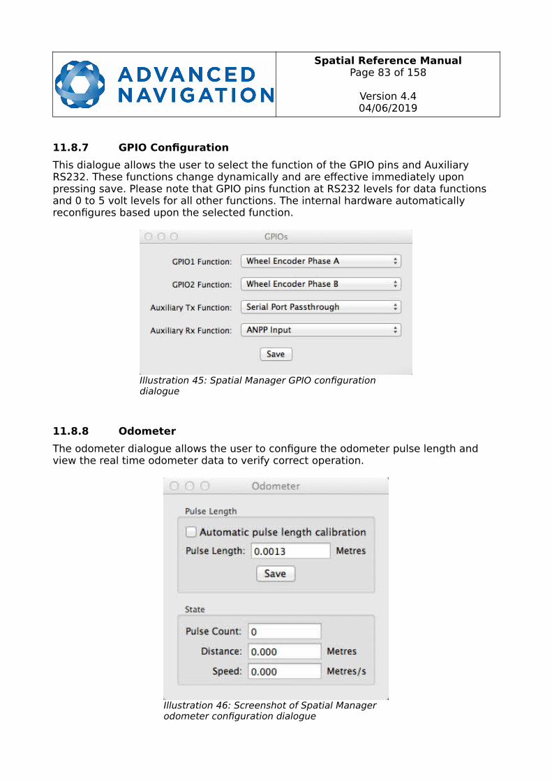
Spatial Reference ManualPage 83 of 158
Version 4.404/06/2019
11.8.7 GPIO Configuration
This dialogue allows the user to select the function of the GPIO pins and Auxiliary RS232. These functions change dynamically and are effective immediately upon pressing save. Please note that GPIO pins function at RS232 levels for data functions and 0 to 5 volt levels for all other functions. The internal hardware automatically reconfigures based upon the selected function.
11.8.8 Odometer
The odometer dialogue allows the user to configure the odometer pulse length and view the real time odometer data to verify correct operation.
Illustration 45: Spatial Manager GPIO configuration dialogue
Illustration 46: Screenshot of Spatial Manager odometer configuration dialogue

Spatial Reference ManualPage 84 of 158
Version 4.404/06/2019
11.8.9 Reset
The reset button causes the system to perform a power cycle as if the unit had the power removed and reapplied. The factory restore button causes the system to erase all settings and restore factory defaults. It also erases the hot start data so that the system is forced to perform a cold start.
11.8.10 Reference Position Offsets
The reference point offsets dialogue allows the user to adjust the point of measurement away from its default position at the centre of the Spatial unit. The primary reference point offset applies to data from all ANPP packets as well as all peripheral output such as NMEA and heave point 1. The heave points 2 to 4 allow the user to offset reference points for the heave values 2 to 4 in the Heave Packet.
Illustration 47: Screenshot of Spatial Manager reset dialogue
Illustration 48: Screenshot of Spatial Manager reference position offsets dialogue
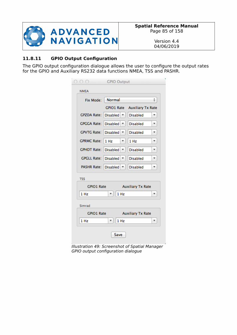
Spatial Reference ManualPage 85 of 158
Version 4.404/06/2019
11.8.11 GPIO Output Configuration
The GPIO output configuration dialogue allows the user to configure the output rates for the GPIO and Auxiliary RS232 data functions NMEA, TSS and PASHR.
Illustration 49: Screenshot of Spatial Manager GPIO output configuration dialogue
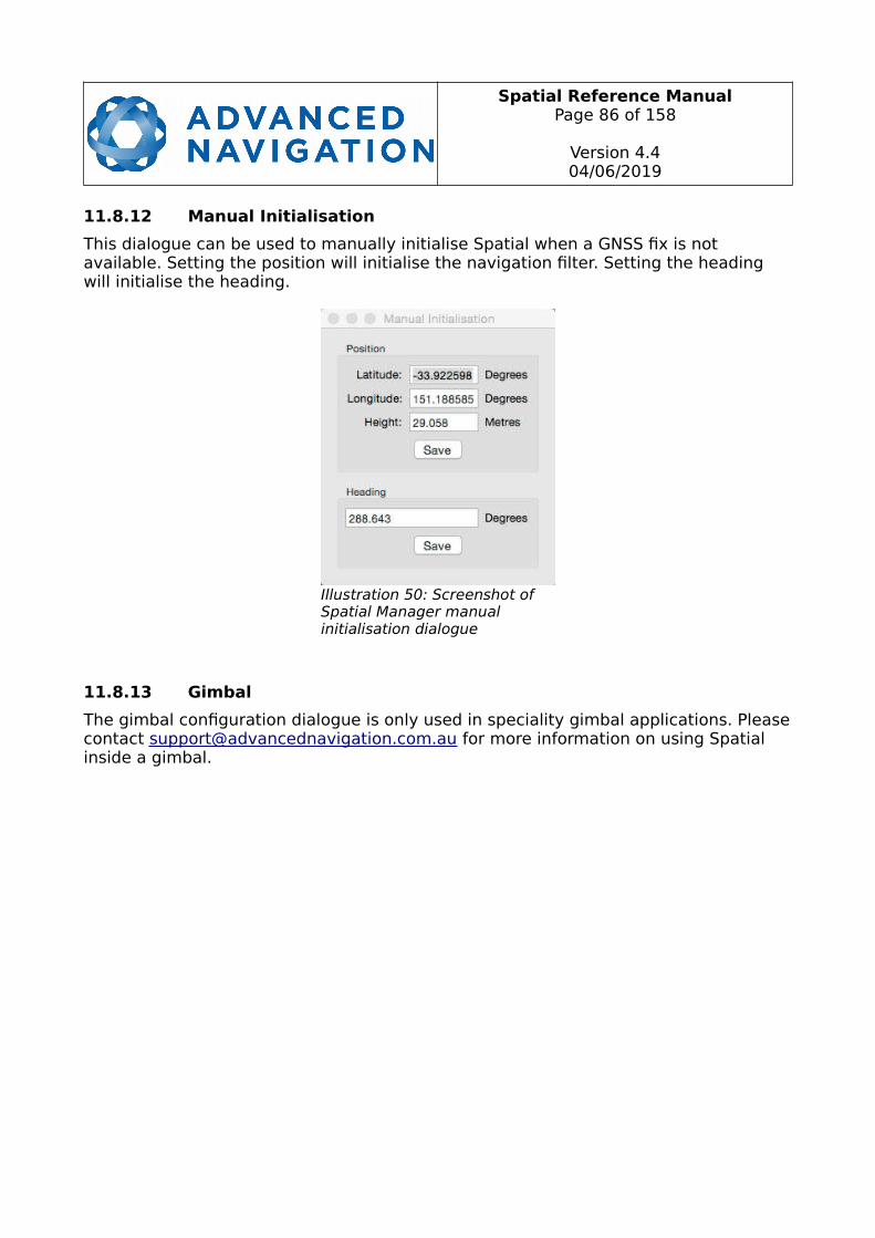
Spatial Reference ManualPage 86 of 158
Version 4.404/06/2019
11.8.12 Manual Initialisation
This dialogue can be used to manually initialise Spatial when a GNSS fix is not available. Setting the position will initialise the navigation filter. Setting the heading will initialise the heading.
11.8.13 Gimbal
The gimbal configuration dialogue is only used in speciality gimbal applications. Pleasecontact [email protected] for more information on using Spatial inside a gimbal.
Illustration 50: Screenshot of Spatial Manager manual initialisation dialogue
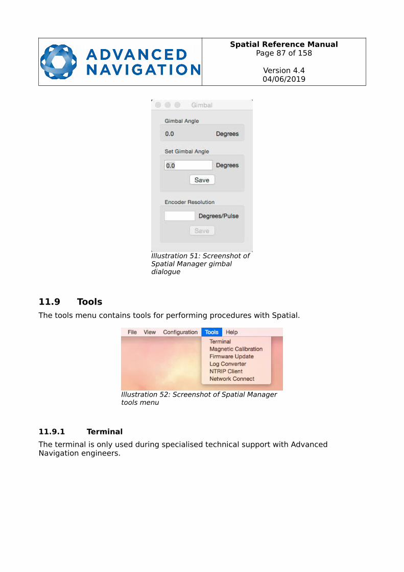
Spatial Reference ManualPage 87 of 158
Version 4.404/06/2019
11.9 Tools
The tools menu contains tools for performing procedures with Spatial.
11.9.1 Terminal
The terminal is only used during specialised technical support with Advanced Navigation engineers.
Illustration 52: Screenshot of Spatial Manager tools menu
Illustration 51: Screenshot of Spatial Manager gimbal dialogue
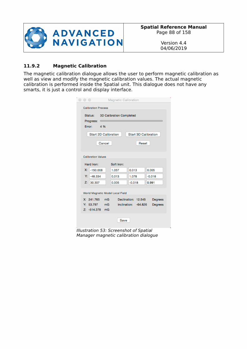
Spatial Reference ManualPage 88 of 158
Version 4.404/06/2019
11.9.2 Magnetic Calibration
The magnetic calibration dialogue allows the user to perform magnetic calibration as well as view and modify the magnetic calibration values. The actual magnetic calibration is performed inside the Spatial unit. This dialogue does not have any smarts, it is just a control and display interface.
Illustration 53: Screenshot of Spatial Manager magnetic calibration dialogue

Spatial Reference ManualPage 89 of 158
Version 4.404/06/2019
11.9.3 Firmware Update
The firmware update dialogue is used to update Spatial's firmware. Advanced Navigation firmware files have the extension .anfw. The dialogue shows the version number of the firmware file along with the date and time it was generated by engineering.
11.9.4 Log Converter
This tool allows the user to convert Spatial log files into various standard formats that are readable by many programs. The offset is used to project the exported position to a point other than the centre of the Spatial unit. For most users these values should beleft at zero.
Illustration 54: Screenshot of Spatial Manager firmware update dialogue
Illustration 55: Screenshot of Spatial Manager log converter dialogue
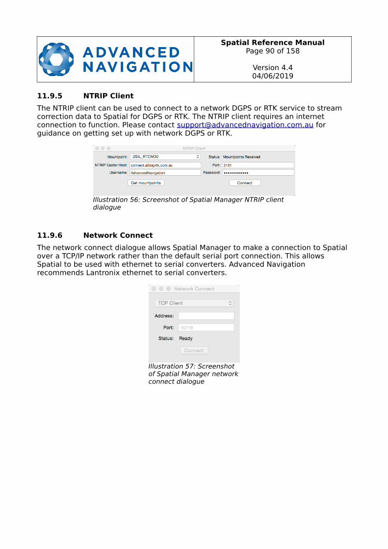
Spatial Reference ManualPage 90 of 158
Version 4.404/06/2019
11.9.5 NTRIP Client
The NTRIP client can be used to connect to a network DGPS or RTK service to stream correction data to Spatial for DGPS or RTK. The NTRIP client requires an internet connection to function. Please contact [email protected] for guidance on getting set up with network DGPS or RTK.
11.9.6 Network Connect
The network connect dialogue allows Spatial Manager to make a connection to Spatial over a TCP/IP network rather than the default serial port connection. This allows Spatial to be used with ethernet to serial converters. Advanced Navigation recommends Lantronix ethernet to serial converters.
Illustration 56: Screenshot of Spatial Manager NTRIP client dialogue
Illustration 57: Screenshot of Spatial Manager networkconnect dialogue
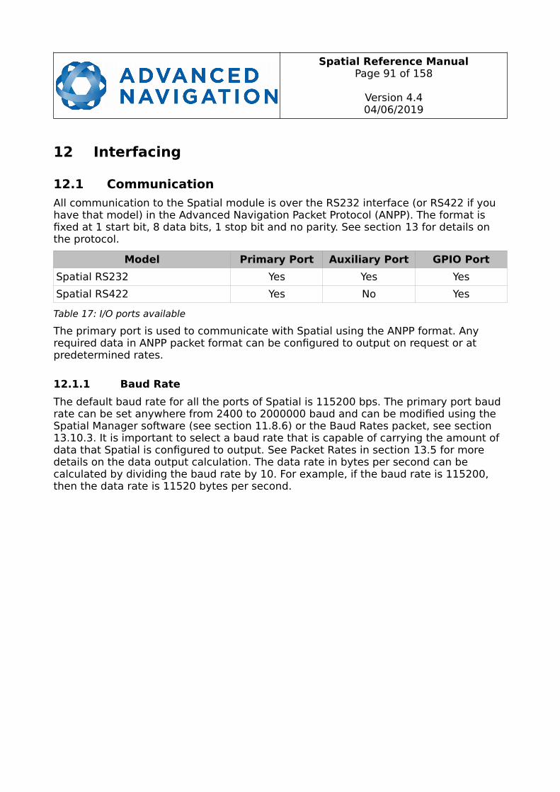
Spatial Reference ManualPage 91 of 158
Version 4.404/06/2019
12 Interfacing
12.1 Communication
All communication to the Spatial module is over the RS232 interface (or RS422 if you have that model) in the Advanced Navigation Packet Protocol (ANPP). The format is fixed at 1 start bit, 8 data bits, 1 stop bit and no parity. See section 13 for details on the protocol.
Model Primary Port Auxiliary Port GPIO Port
Spatial RS232 Yes Yes Yes
Spatial RS422 Yes No Yes
Table 17: I/O ports available
The primary port is used to communicate with Spatial using the ANPP format. Any required data in ANPP packet format can be configured to output on request or at predetermined rates.
12.1.1 Baud Rate
The default baud rate for all the ports of Spatial is 115200 bps. The primary port baud rate can be set anywhere from 2400 to 2000000 baud and can be modified using the Spatial Manager software (see section 11.8.6) or the Baud Rates packet, see section13.10.3. It is important to select a baud rate that is capable of carrying the amount of data that Spatial is configured to output. See Packet Rates in section 13.5 for more details on the data output calculation. The data rate in bytes per second can be calculated by dividing the baud rate by 10. For example, if the baud rate is 115200, then the data rate is 11520 bytes per second.
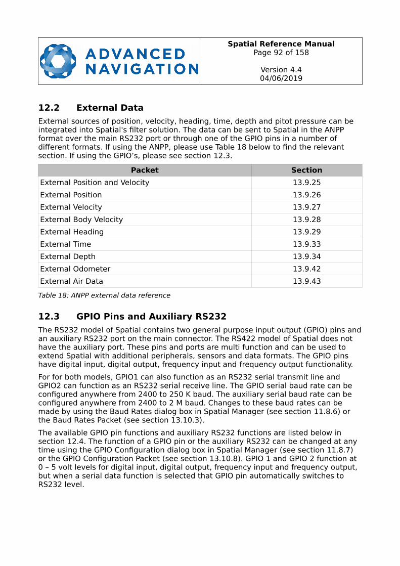
Spatial Reference ManualPage 92 of 158
Version 4.404/06/2019
12.2 External Data
External sources of position, velocity, heading, time, depth and pitot pressure can be integrated into Spatial's filter solution. The data can be sent to Spatial in the ANPP format over the main RS232 port or through one of the GPIO pins in a number of different formats. If using the ANPP, please use Table 18 below to find the relevant section. If using the GPIO’s, please see section 12.3.
Packet Section
External Position and Velocity 13.9.25
External Position 13.9.26
External Velocity 13.9.27
External Body Velocity 13.9.28
External Heading 13.9.29
External Time 13.9.33
External Depth 13.9.34
External Odometer 13.9.42
External Air Data 13.9.43
Table 18: ANPP external data reference
12.3 GPIO Pins and Auxiliary RS232
The RS232 model of Spatial contains two general purpose input output (GPIO) pins andan auxiliary RS232 port on the main connector. The RS422 model of Spatial does not have the auxiliary port. These pins and ports are multi function and can be used to extend Spatial with additional peripherals, sensors and data formats. The GPIO pins have digital input, digital output, frequency input and frequency output functionality.
For for both models, GPIO1 can also function as an RS232 serial transmit line and GPIO2 can function as an RS232 serial receive line. The GPIO serial baud rate can be configured anywhere from 2400 to 250 K baud. The auxiliary serial baud rate can be configured anywhere from 2400 to 2 M baud. Changes to these baud rates can be made by using the Baud Rates dialog box in Spatial Manager (see section 11.8.6) or the Baud Rates Packet (see section 13.10.3).
The available GPIO pin functions and auxiliary RS232 functions are listed below in section 12.4. The function of a GPIO pin or the auxiliary RS232 can be changed at any time using the GPIO Configuration dialog box in Spatial Manager (see section 11.8.7) or the GPIO Configuration Packet (see section 13.10.8). GPIO 1 and GPIO 2 function at 0 – 5 volt levels for digital input, digital output, frequency input and frequency output, but when a serial data function is selected that GPIO pin automatically switches to RS232 level.
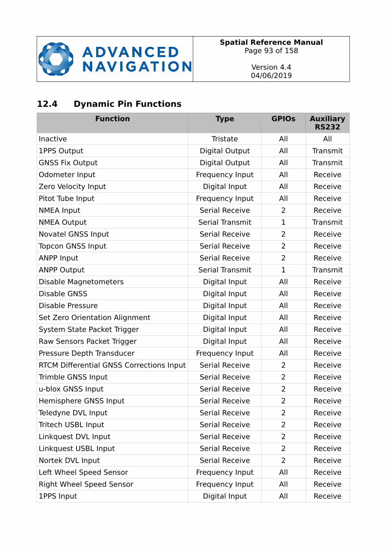
Spatial Reference ManualPage 93 of 158
Version 4.404/06/2019
12.4 Dynamic Pin Functions
Function Type GPIOs AuxiliaryRS232
Inactive Tristate All All
1PPS Output Digital Output All Transmit
GNSS Fix Output Digital Output All Transmit
Odometer Input Frequency Input All Receive
Zero Velocity Input Digital Input All Receive
Pitot Tube Input Frequency Input All Receive
NMEA Input Serial Receive 2 Receive
NMEA Output Serial Transmit 1 Transmit
Novatel GNSS Input Serial Receive 2 Receive
Topcon GNSS Input Serial Receive 2 Receive
ANPP Input Serial Receive 2 Receive
ANPP Output Serial Transmit 1 Transmit
Disable Magnetometers Digital Input All Receive
Disable GNSS Digital Input All Receive
Disable Pressure Digital Input All Receive
Set Zero Orientation Alignment Digital Input All Receive
System State Packet Trigger Digital Input All Receive
Raw Sensors Packet Trigger Digital Input All Receive
Pressure Depth Transducer Frequency Input All Receive
RTCM Differential GNSS Corrections Input Serial Receive 2 Receive
Trimble GNSS Input Serial Receive 2 Receive
u-blox GNSS Input Serial Receive 2 Receive
Hemisphere GNSS Input Serial Receive 2 Receive
Teledyne DVL Input Serial Receive 2 Receive
Tritech USBL Input Serial Receive 2 Receive
Linkquest DVL Input Serial Receive 2 Receive
Linkquest USBL Input Serial Receive 2 Receive
Nortek DVL Input Serial Receive 2 Receive
Left Wheel Speed Sensor Frequency Input All Receive
Right Wheel Speed Sensor Frequency Input All Receive
1PPS Input Digital Input All Receive
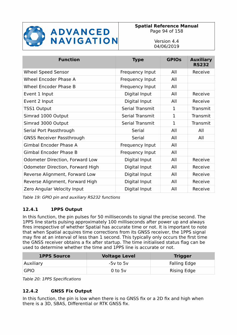
Spatial Reference ManualPage 94 of 158
Version 4.404/06/2019
Function Type GPIOs AuxiliaryRS232
Wheel Speed Sensor Frequency Input All Receive
Wheel Encoder Phase A Frequency Input All
Wheel Encoder Phase B Frequency Input All
Event 1 Input Digital Input All Receive
Event 2 Input Digital Input All Receive
TSS1 Output Serial Transmit 1 Transmit
Simrad 1000 Output Serial Transmit 1 Transmit
Simrad 3000 Output Serial Transmit 1 Transmit
Serial Port Passthrough Serial All All
GNSS Receiver Passthrough Serial All All
Gimbal Encoder Phase A Frequency Input All
Gimbal Encoder Phase B Frequency Input All
Odometer Direction, Forward Low Digital Input All Receive
Odometer Direction, Forward High Digital Input All Receive
Reverse Alignment, Forward Low Digital Input All Receive
Reverse Alignment, Forward High Digital Input All Receive
Zero Angular Velocity Input Digital Input All Receive
Table 19: GPIO pin and auxiliary RS232 functions
12.4.1 1PPS Output
In this function, the pin pulses for 50 milliseconds to signal the precise second. The 1PPS line starts pulsing approximately 100 milliseconds after power up and always fires irrespective of whether Spatial has accurate time or not. It is important to note that when Spatial acquires time corrections from its GNSS receiver, the 1PPS signal may fire at an interval of less than 1 second. This typically only occurs the first time the GNSS receiver obtains a fix after startup. The time initialised status flag can be used to determine whether the time and 1PPS line is accurate or not.
1PPS Source Voltage Level Trigger
Auxiliary -5v to 5v Falling Edge
GPIO 0 to 5v Rising Edge
Table 20: 1PPS Specifications
12.4.2 GNSS Fix Output
In this function, the pin is low when there is no GNSS fix or a 2D fix and high when there is a 3D, SBAS, Differential or RTK GNSS fix.
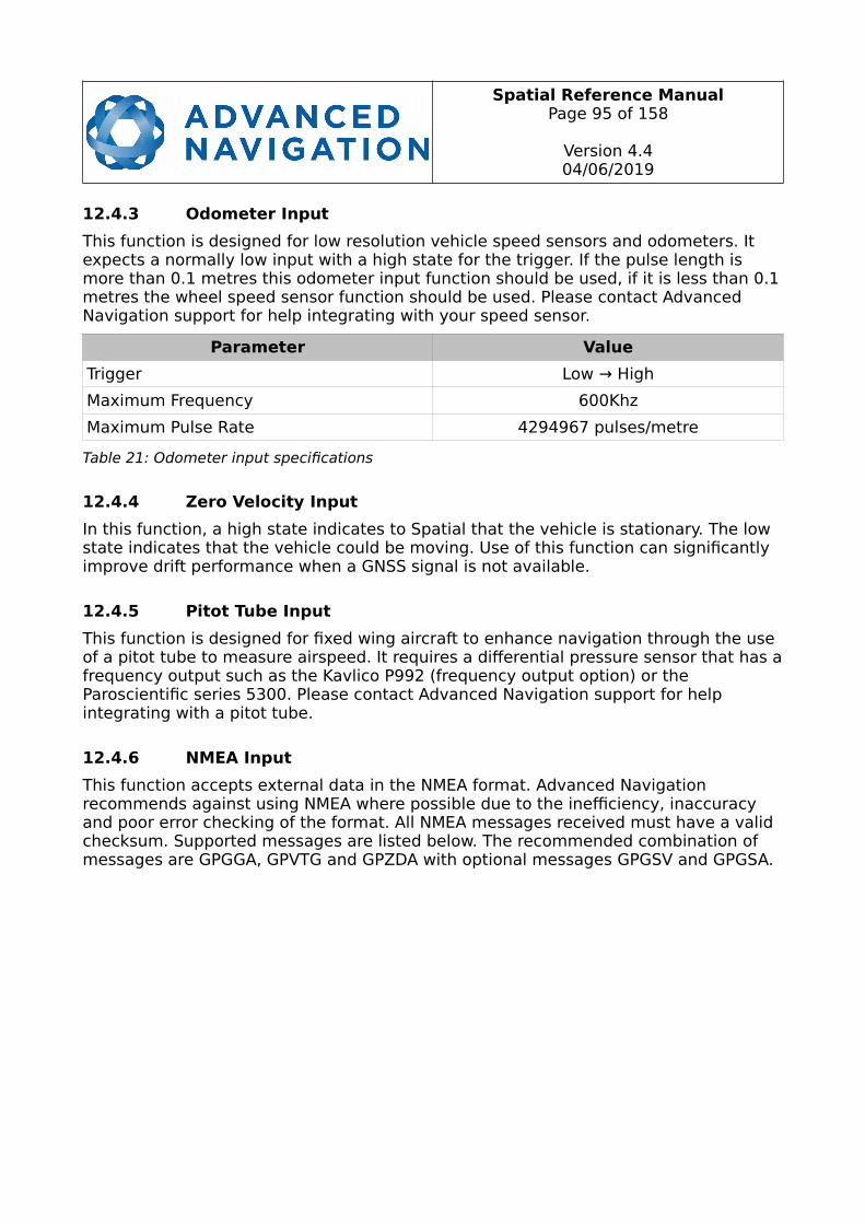
Spatial Reference ManualPage 95 of 158
Version 4.404/06/2019
12.4.3 Odometer Input
This function is designed for low resolution vehicle speed sensors and odometers. It expects a normally low input with a high state for the trigger. If the pulse length is more than 0.1 metres this odometer input function should be used, if it is less than 0.1metres the wheel speed sensor function should be used. Please contact Advanced Navigation support for help integrating with your speed sensor.
Parameter Value
Trigger Low → High
Maximum Frequency 600Khz
Maximum Pulse Rate 4294967 pulses/metre
Table 21: Odometer input specifications
12.4.4 Zero Velocity Input
In this function, a high state indicates to Spatial that the vehicle is stationary. The low state indicates that the vehicle could be moving. Use of this function can significantly improve drift performance when a GNSS signal is not available.
12.4.5 Pitot Tube Input
This function is designed for fixed wing aircraft to enhance navigation through the use of a pitot tube to measure airspeed. It requires a differential pressure sensor that has afrequency output such as the Kavlico P992 (frequency output option) or the Paroscientific series 5300. Please contact Advanced Navigation support for help integrating with a pitot tube.
12.4.6 NMEA Input
This function accepts external data in the NMEA format. Advanced Navigation recommends against using NMEA where possible due to the inefficiency, inaccuracy and poor error checking of the format. All NMEA messages received must have a valid checksum. Supported messages are listed below. The recommended combination of messages are GPGGA, GPVTG and GPZDA with optional messages GPGSV and GPGSA.

Spatial Reference ManualPage 96 of 158
Version 4.404/06/2019
Message ID Description
GPGGAGNGGA
3D position
GPGLLGNGLL
2D position
GPRMCGNRMC
2D position, 2D velocity and coarse time
GPVTGGNVTG
2D velocity
GPHDTGNHDTHEHDT
Heading
GPGSVGNGSV
Satellites
GPGSAGNGSA
Dilution of Position
GPZDAGNZDA
Time
Table 22: Supported NMEA input messages
12.4.7 NMEA Output
This function outputs a configurable combination of NMEA messages at up to 50 Hz. The messages output and the output rate can be configured using the NMEA output configuration dialogue in Spatial Manager. A complete list of available messages can be found in section 13.10.15.
Advanced Navigation recommends against using NMEA where possible due to the inefficiency, inaccuracy and poor error checking of the format.
An example output is shown below.
$GPZDA,031644.460,07,05,2013,00,00*52
$GPGGA,031644.460,3352.3501851,S,15112.2355488,E,6,00,1.4,150.0,M,0.0,M,,*7E
$GPVTG,089.19,T,089.19,M,000.00,N,000.00,K,E*27
$GPRMC,031644.460,A,3352.3501851,S,15112.2355488,E,0.0,89.2,070513,12.5,W,E*02
$GPHDT,89.2,T*06
$PASHR,031644.460,089.19,T,-00.01,-00.47,-00.00,,,,0,0*2E
12.4.8 Novatel GNSS Input
This function is designed for interfacing Spatial with a Novatel GNSS receiver. It accepts data in the Novatel binary format and requires messages BESTPOSB and BESTVELB at rates higher than 1 Hz (20Hz recommended). The message BESTSATSB isoptional to display detailed satellite information. The message HEADING is also supported for ALIGN capable receivers.
Spatial Reference ManualPage 97 of 158
Version 4.404/06/2019
12.4.9 Topcon GNSS Input
This function is designed for interfacing Spatial with a Topcon GNSS receiver. It acceptsdata in the GRIL TPS binary format and expects messages PG and VG at rates higher than 1 Hz.
12.4.10 ANPP Input
This function accepts data in the ANPP format as specified in section 13.
12.4.11 ANPP Output
This function outputs data in the ANPP format as specified in section 13. For packets tobe sent out they must be requested through another GPIO functioning as ANPP input. This function is also used when connecting two Spatial units together, for example when using a USBL.
12.4.12 Disable Magnetometers
This function accepts a digital input with a low state enabling the magnetometers and a high state disabling the magnetometers.
12.4.13 Disable GNSS
This function accepts a digital input with a low state enabling the GNSS and a high state disabling the GNSS.
12.4.14 Disable Pressure
This function accepts a digital input with a low state enabling the atmospheric pressure sensor and a high state disabling the atmospheric pressure sensor.
12.4.15 Set Zero Orientation Alignment
This function accepts a digital input. The input is normally low and a transition from low to high causes Spatial to set its alignment so that the current orientation is zero. Due to the risk of exhausting the flash cycles, the change is not permanent and will disappear on reset. To make it permanent the Installation Alignment Packet must be read and then sent back to Spatial with the permanent flag set. This function requires de-bouncing if attached to a switch.
12.4.16 System State Packet Trigger
This function accepts a digital input. The input is normally low and a transition from low to high causes Spatial to send the system state packet. This function requires de-bouncing if attached to a switch.
12.4.17 Raw Sensors Packet Trigger
This function accepts a digital input. The input is normally low and a transition from low to high causes Spatial to send the raw sensors packet. This function requires de-
Spatial Reference ManualPage 98 of 158
Version 4.404/06/2019
bouncing if attached to a switch.
12.4.18 Pressure Depth Transducer
This function is designed for interfacing with a legacy pressure depth transducer. These are no longer available and the function is now deprecated.
12.4.19 RTCM Differential GNSS Corrections Input
This function accepts RTCM v3 differential and RTK GNSS corrections. This allows for Differential and RTK GNSS with Spatial's internal GNSS receiver.
12.4.20 Trimble GNSS Input
This function is designed for interfacing Spatial with a Trimble GNSS receiver. It accepts data in the Trimble binary format GSOF and expects packet 0x40 with records 1, 2, 8, and 12 at rates higher than 1Hz (20Hz recommended) and optional records 9 and 34 at 1 to 2Hz.
12.4.21 u-blox GNSS Input
This function is designed for interfacing Spatial with a u-blox GNSS receiver. It accepts data in the u-blox binary format and expects message NAV-PVT or NAV-SOL at rates higher than 1Hz.
12.4.22 Hemisphere GNSS Input
This function is designed for interfacing Spatial with a Hemisphere GNSS receiver. It accepts data in the Hemisphere binary format and expects message Bin1 at rates higher than 1Hz. For Hemisphere receivers that provide heading using two antennas, NMEA should be used instead as the binary format does not allow for transmission of heading information.
12.4.23 Teledyne DVL Input
This function accepts DVL data from a Teledyne DVL. For assistance with configurationplease contact [email protected].
12.4.24 Tritech USBL Input
This function accepts USBL data from a Tritech USBL. For assistance with configurationplease contact [email protected].
12.4.25 Linkquest DVL Input
This function accepts DVL data from a Linkquest DVL. For assistance with configuration please contact [email protected].
12.4.26 Linkquest USBL Input
This function accepts USBL data from a Linkquest USBL. For assistance with
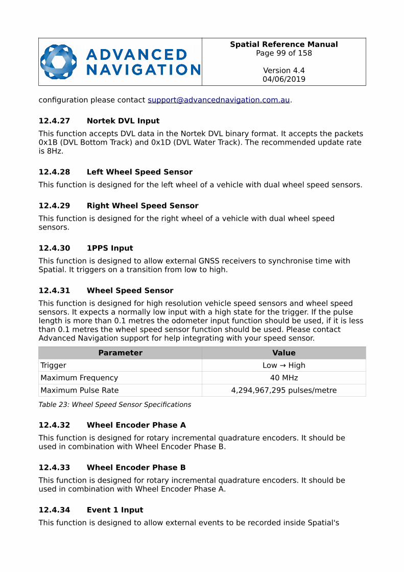
Spatial Reference ManualPage 99 of 158
Version 4.404/06/2019
configuration please contact [email protected].
12.4.27 Nortek DVL Input
This function accepts DVL data in the Nortek DVL binary format. It accepts the packets0x1B (DVL Bottom Track) and 0x1D (DVL Water Track). The recommended update rate is 8Hz.
12.4.28 Left Wheel Speed Sensor
This function is designed for the left wheel of a vehicle with dual wheel speed sensors.
12.4.29 Right Wheel Speed Sensor
This function is designed for the right wheel of a vehicle with dual wheel speed sensors.
12.4.30 1PPS Input
This function is designed to allow external GNSS receivers to synchronise time with Spatial. It triggers on a transition from low to high.
12.4.31 Wheel Speed Sensor
This function is designed for high resolution vehicle speed sensors and wheel speed sensors. It expects a normally low input with a high state for the trigger. If the pulse length is more than 0.1 metres the odometer input function should be used, if it is lessthan 0.1 metres the wheel speed sensor function should be used. Please contact Advanced Navigation support for help integrating with your speed sensor.
Parameter Value
Trigger Low → High
Maximum Frequency 40 MHz
Maximum Pulse Rate 4,294,967,295 pulses/metre
Table 23: Wheel Speed Sensor Specifications
12.4.32 Wheel Encoder Phase A
This function is designed for rotary incremental quadrature encoders. It should be used in combination with Wheel Encoder Phase B.
12.4.33 Wheel Encoder Phase B
This function is designed for rotary incremental quadrature encoders. It should be used in combination with Wheel Encoder Phase A.
12.4.34 Event 1 Input
This function is designed to allow external events to be recorded inside Spatial's

Spatial Reference ManualPage 100 of 158
Version 4.404/06/2019
output. The event is recorded in the filter status, see section 13.9.1.2, and resets after the next packet is output. The event triggers on a transition from low to high.
12.4.35 Event 2 Input
This function is designed to allow external events to be recorded inside Spatial's output. The event is recorded in the filter status, see section 13.9.1.2, and resets after the next packet is output. The event triggers on a transition from low to high.
12.4.36 TSS1 Output
This function outputs the TSS1 format at a user configurable rate up to 50 Hz. The output rate can be configured using the GPIO output configuration dialogue in Spatial Manager, see section 11.8.11.
12.4.37 Simrad 1000 Output
This function outputs the Simrad 1000 format at a user configurable rate up to 50 Hz. The output rate can be configured using the GPIO output configuration dialogue in Spatial Manager, see section 11.8.11.
12.4.38 Simrad 3000 Output
This function outputs the Simrad 3000 format at a user configurable rate up to 50 Hz. The output rate can be configured using the GPIO output configuration dialogue in Spatial Manager, see section 11.8.11.
12.4.39 Serial Port Passthrough
This function allows passthrough communication through either GPIO 1 and 2 or the Auxiliary RS232. To transmit data use the Serial Port Pass-through Packet. When data is received it will be sent back using the same Serial Port Pass-through Packet.
12.4.40 GNSS Receiver Passthrough
This function allows for pass through connection to the internal GNSS receiver. This is useful for firmware updates of the internal GNSS receiver.
12.4.41 Gimbal Encoder Phase A
This function is designed for interfacing with a rotary incremental quadrature encoder to measure the azimuth angle of a gimbal that Spatial is installed in. It should be used in combination with Gimbal Encoder Phase B.
12.4.42 Gimbal Encoder Phase B
This function is designed for interfacing with a rotary incremental quadrature encoder to measure the azimuth angle of a gimbal that Spatial is installed in. It should be used in combination with Gimbal Encoder Phase A.

Spatial Reference ManualPage 101 of 158
Version 4.404/06/2019
12.4.43 Odometer Direction, Forward Low
This function is designed to take a reversing indication input for direction with an odometer or wheel encoder. It should be used in combination with Odometer Input orWheel Speed Sensor.
12.4.44 Odometer Direction, Forward High
This function is designed to take a reversing indication input for direction with an odometer or wheel encoder. It should be used in combination with Odometer Input orWheel Speed Sensor.
12.4.45 Reverse Alignment, Forward Low
This function is designed to reverse the alignment settings for vehicles that can have two vehicle forward directions, such as locomotives.
12.4.46 Reverse Alignment, Forward High
This function is designed to reverse the alignment settings for vehicles that can have two vehicle forward directions, such as locomotives.

Spatial Reference ManualPage 102 of 158
Version 4.404/06/2019
12.4.47 Zero Angular Velocity Input
In this function, a high state indicates to Spatial that the vehicle is not rotating. The low state indicates that the vehicle could be rotating. Use of this function can significantly improve heading drift performance when a GNSS signal is not available.
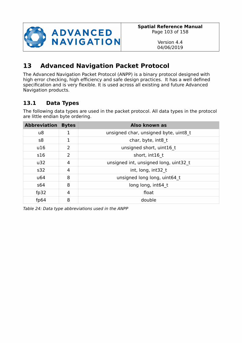
Spatial Reference ManualPage 103 of 158
Version 4.404/06/2019
13 Advanced Navigation Packet ProtocolThe Advanced Navigation Packet Protocol (ANPP) is a binary protocol designed with high error checking, high efficiency and safe design practices. It has a well defined specification and is very flexible. It is used across all existing and future Advanced Navigation products.
13.1 Data Types
The following data types are used in the packet protocol. All data types in the protocol are little endian byte ordering.
Abbreviation Bytes Also known as
u8 1 unsigned char, unsigned byte, uint8_t
s8 1 char, byte, int8_t
u16 2 unsigned short, uint16_t
s16 2 short, int16_t
u32 4 unsigned int, unsigned long, uint32_t
s32 4 int, long, int32_t
u64 8 unsigned long long, uint64_t
s64 8 long long, int64_t
fp32 4 float
fp64 8 double
Table 24: Data type abbreviations used in the ANPP

Spatial Reference ManualPage 104 of 158
Version 4.404/06/2019
13.2 Packet Structure
The ANPP packet structure is shown in Table 25 and the header format is shown inTable 26. Example code can be downloaded from the software section.
Header
Header LRC Packet ID Packet Length CRC16 Packet Data
Table 25: ANPP packet structure
ANPP Header Format
Field#
BytesOffset
DataType
Size Description
1 0 u8 1 Header LRC, see section 13.2.1
2 1 u8 1 Packet ID, see section 13.2.2
3 2 u8 1 Packet Length, see section 13.2.3
4 3 u16 2 CRC16, see section 13.2.4
Table 26: ANPP header format
13.2.1 Header LRC
The header LRC (Longitudinal Redundancy Check) provides error checking on the packet header. It also allows the decoder to find the start of a packet by scanning for avalid LRC. The LRC can be found using the following:
LRC = ((packet_id + packet_length + crc[0] + crc[1])^0xFF) + 1
13.2.2 Packet ID
The packet ID is used to distinguish the contents of the packet. Packet IDs range from 0 to 255.
Within this range there are three different sub-ranges, these are system packets, statepackets and configuration packets.
System packets have packet IDs in the range 0 to 19. These packets are implemented the same by every device using ANPP.
State packets are packets that contain data that changes with time, i.e. temperature. State packets can be set to output at a certain rate. State packets are packet IDs in the range 20 to 179.
Configuration packets are used for reading and writing device configuration. Configuration packets are packet IDs in the range 180 to 255.
Spatial Reference ManualPage 105 of 158
Version 4.404/06/2019
13.2.3 Packet Length
The packet length denotes the length of the packet data, i.e. from byte index 5 onwards inclusive. Packet length has a range of 0 – 255.
13.2.4 CRC
The CRC is a CRC16-CCITT. The starting value is 0xFFFF. The CRC covers only the packet data.
13.3 Packet Requests
Any packet can be requested at any time using the request packet. See section 13.8.2.
13.4 Packet Acknowledgement
When configuration packets are sent to Spatial, it will reply with an acknowledgement packet that indicates whether the configuration change was successful or not. For details on the acknowledgement packet, see section 13.8.1.
External data packets will also generate negative acknowledgement packets if there isa problem with the packet. Positive acknowledgements will not be sent.
13.5 Packet Rates
The packet rates can be configured either using Spatial Manager or through thePackets Period Packet. By default Spatial is configured to output the System State Packet at 50Hz. When configuring packet rates it is essential to ensure the baud rate iscapable of handling the data throughput. This can be calculated using the rate and packet size. The packet size is the packet length add five to account for the packet overhead. For example to output the system state packet at 50Hz the calculation would be:
Data throughput = (100 (packet length) + 5 (fixed packet overhead)) * 50 (rate)
Data throughput = 5250 bytes per second
Minimum baud rate = data throughput x 11 = 57750 Baud
Closest standard baud rate = 115200 Baud
When multiple packets are set to output at the same rate, the order the packets output is from lowest ID to highest ID.
13.6 Packet Timing
Packets are output in order of packet ID from lowest ID to highest ID and all packets that are output in one sequence have their data matched to the same time of validity. The time of validity can be found in either the System State Packet, the Unix Time Packet or the Formatted Time Packet. For example if the Unix Time Packet, Status Packet and NED Velocity Packet packet were all set to output at 10 Hz, at each 0.1 second period the three packets would output consecutively by order of packet ID withall data synchronised between them and the Unix Time Packet providing the time of

Spatial Reference ManualPage 106 of 158
Version 4.404/06/2019
validity for the other two packets.
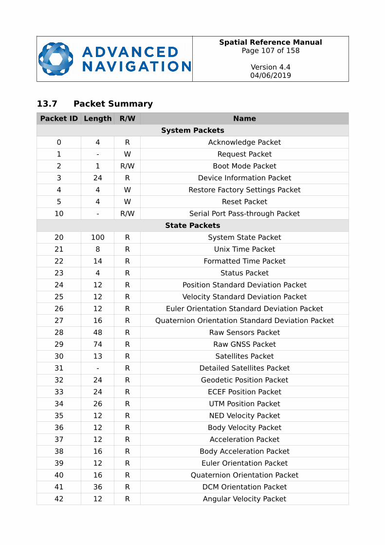
Spatial Reference ManualPage 107 of 158
Version 4.404/06/2019
13.7 Packet Summary
Packet ID Length R/W Name
System Packets
0 4 R Acknowledge Packet
1 - W Request Packet
2 1 R/W Boot Mode Packet
3 24 R Device Information Packet
4 4 W Restore Factory Settings Packet
5 4 W Reset Packet
10 - R/W Serial Port Pass-through Packet
State Packets
20 100 R System State Packet
21 8 R Unix Time Packet
22 14 R Formatted Time Packet
23 4 R Status Packet
24 12 R Position Standard Deviation Packet
25 12 R Velocity Standard Deviation Packet
26 12 R Euler Orientation Standard Deviation Packet
27 16 R Quaternion Orientation Standard Deviation Packet
28 48 R Raw Sensors Packet
29 74 R Raw GNSS Packet
30 13 R Satellites Packet
31 - R Detailed Satellites Packet
32 24 R Geodetic Position Packet
33 24 R ECEF Position Packet
34 26 R UTM Position Packet
35 12 R NED Velocity Packet
36 12 R Body Velocity Packet
37 12 R Acceleration Packet
38 16 R Body Acceleration Packet
39 12 R Euler Orientation Packet
40 16 R Quaternion Orientation Packet
41 36 R DCM Orientation Packet
42 12 R Angular Velocity Packet
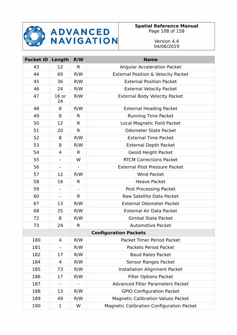
Spatial Reference ManualPage 108 of 158
Version 4.404/06/2019
Packet ID Length R/W Name
43 12 R Angular Acceleration Packet
44 60 R/W External Position & Velocity Packet
45 36 R/W External Position Packet
46 24 R/W External Velocity Packet
47 16 or24
R/W External Body Velocity Packet
48 8 R/W External Heading Packet
49 8 R Running Time Packet
50 12 R Local Magnetic Field Packet
51 20 R Odometer State Packet
52 8 R/W External Time Packet
53 8 R/W External Depth Packet
54 4 R Geoid Height Packet
55 - W RTCM Corrections Packet
56 - - External Pitot Pressure Packet
57 12 R/W Wind Packet
58 16 R Heave Packet
59 - - Post Processing Packet
60 - R Raw Satellite Data Packet
67 13 R/W External Odometer Packet
68 25 R/W External Air Data Packet
72 8 R/W Gimbal State Packet
73 24 R Automotive Packet
Configuration Packets
180 4 R/W Packet Timer Period Packet
181 - R/W Packets Period Packet
182 17 R/W Baud Rates Packet
184 4 R/W Sensor Ranges Packet
185 73 R/W Installation Alignment Packet
186 17 R/W Filter Options Packet
187 - - Advanced Filter Parameters Packet
188 13 R/W GPIO Configuration Packet
189 49 R/W Magnetic Calibration Values Packet
190 1 W Magnetic Calibration Configuration Packet
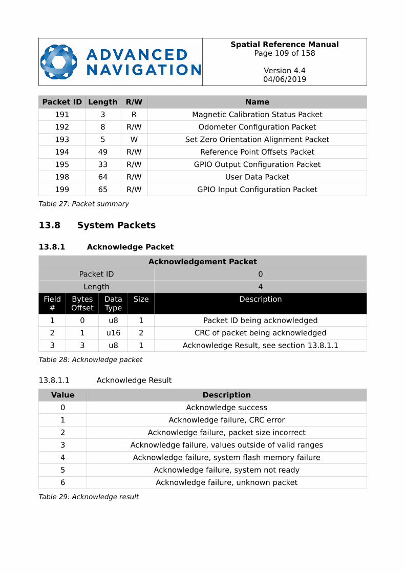
Spatial Reference ManualPage 109 of 158
Version 4.404/06/2019
Packet ID Length R/W Name
191 3 R Magnetic Calibration Status Packet
192 8 R/W Odometer Configuration Packet
193 5 W Set Zero Orientation Alignment Packet
194 49 R/W Reference Point Offsets Packet
195 33 R/W GPIO Output Configuration Packet
198 64 R/W User Data Packet
199 65 R/W GPIO Input Configuration Packet
Table 27: Packet summary
13.8 System Packets
13.8.1 Acknowledge Packet
Acknowledgement Packet
Packet ID 0
Length 4
Field#
BytesOffset
DataType
Size Description
1 0 u8 1 Packet ID being acknowledged
2 1 u16 2 CRC of packet being acknowledged
3 3 u8 1 Acknowledge Result, see section 13.8.1.1
Table 28: Acknowledge packet
13.8.1.1 Acknowledge Result
Value Description
0 Acknowledge success
1 Acknowledge failure, CRC error
2 Acknowledge failure, packet size incorrect
3 Acknowledge failure, values outside of valid ranges
4 Acknowledge failure, system flash memory failure
5 Acknowledge failure, system not ready
6 Acknowledge failure, unknown packet
Table 29: Acknowledge result

Spatial Reference ManualPage 110 of 158
Version 4.404/06/2019
13.8.2 Request Packet
Request Packet
Packet ID 1
Length 1 x number of packets requested
Field#
BytesOffset
DataType
Size Description
1 0 u8 1 Packet ID requested
+ Field 1 repeats for additional packet requests
Table 30: Request packet
13.8.3 Boot Mode Packet
Boot Mode Packet
Packet ID 2
Length 1
Field#
BytesOffset
DataType
Size Description
1 0 u8 1 Boot mode, see section 13.8.3.1
Table 31: Boot mode packet
13.8.3.1 Boot Mode Types
Value Description
0 Bootloader
1 Main Program
Table 32: Boot mode types

Spatial Reference ManualPage 111 of 158
Version 4.404/06/2019
13.8.4 Device Information Packet
Device Information Packet
Packet ID 3
Length 24
Field#
BytesOffset
DataType
Size Description
1 0 u32 4 Software version
2 4 u32 4 Device ID
3 8 u32 4 Hardware revision
4 12 u32 4 Serial number part 1
5 16 u32 4 Serial number part 2
6 20 u32 4 Serial number part 3
Table 33: Device information packet
13.8.5 Restore Factory Settings Packet
Restore Factory Settings Packet
Packet ID 4
Length 4
Field#
BytesOffset
DataType
Size Description
1 0 u32 4 Verification Sequence (set to 0x85429E1C)
Table 34: Restore factory settings packet
13.8.6 Reset Packet
Reset Packet
Packet ID 5
Length 4
Field#
BytesOffset
DataType
Size Description
1 0 u32 4 Verification sequence, see section 13.8.6.1
Table 35: Reset packet
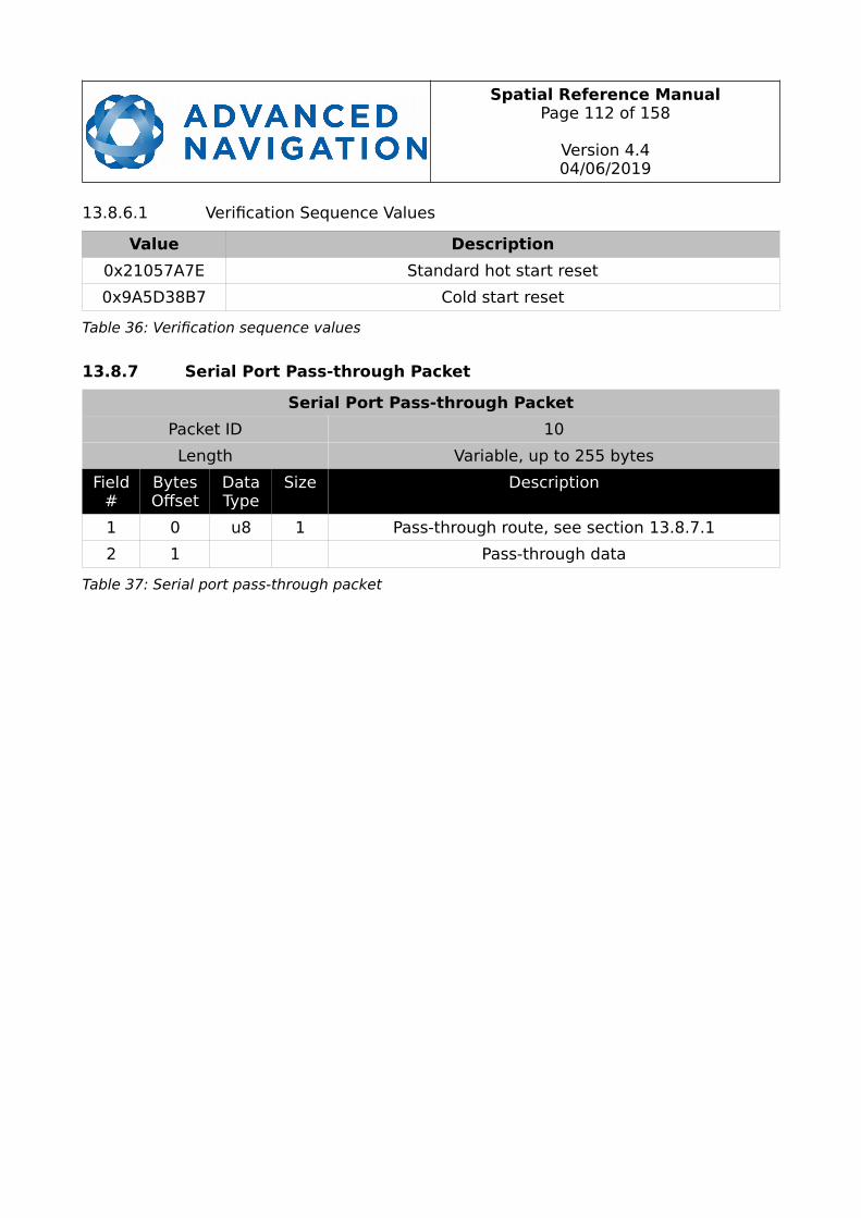
Spatial Reference ManualPage 112 of 158
Version 4.404/06/2019
13.8.6.1 Verification Sequence Values
Value Description
0x21057A7E Standard hot start reset
0x9A5D38B7 Cold start reset
Table 36: Verification sequence values
13.8.7 Serial Port Pass-through Packet
Serial Port Pass-through Packet
Packet ID 10
Length Variable, up to 255 bytes
Field#
BytesOffset
DataType
Size Description
1 0 u8 1 Pass-through route, see section 13.8.7.1
2 1 Pass-through data
Table 37: Serial port pass-through packet

Spatial Reference ManualPage 113 of 158
Version 4.404/06/2019
13.8.7.1 Pass-through Routes
Value Description
1 GPIO 1 and 2
2 Auxiliary RS232
Table 38: Pass-through routes

Spatial Reference ManualPage 114 of 158
Version 4.404/06/2019
13.9 State Packets
Spatial supports a large number of packets providing extensive functionality. However for the majority of users the easiest approach is to configure Spatial using the Spatial Manager software and then support only the single system state packet shown below in section 13.9.1. Advanced functionality can be added as required through the other packets.

Spatial Reference ManualPage 115 of 158
Version 4.404/06/2019
13.9.1 System State Packet
System State Packet
Packet ID 20
Length 100
Field#
BytesOffset
DataType
Size Description
1 0 u16 2 System status, see section 13.9.1.1
2 2 u16 2 Filter status, see section 13.9.1.2
3 4 u32 4 Unix time (seconds), see section 13.9.1.4
4 8 u32 4 Microseconds, see section 13.9.1.5
5 12 fp64 8 Latitude (rad)
6 20 fp64 8 Longitude (rad)
7 28 fp64 8 Height (m)
8 36 fp32 4 Velocity north (m/s)
9 40 fp32 4 Velocity east (m/s)
10 44 fp32 4 Velocity down (m/s)
11 48 fp32 4 Body acceleration X (m/s/s)
12 52 fp32 4 Body acceleration Y (m/s/s)
13 56 fp32 4 Body acceleration Z (m/s/s)
14 60 fp32 4 G force (g)
15 64 fp32 4 Roll (radians)
16 68 fp32 4 Pitch (radians)
17 72 fp32 4 Heading (radians)
18 76 fp32 4 Angular velocity X (rad/s)
19 80 fp32 4 Angular velocity Y (rad/s)
20 84 fp32 4 Angular velocity Z (rad/s)
21 88 fp32 4 Latitude standard deviation (m)
22 92 fp32 4 Longitude standard deviation (m)
23 96 fp32 4 Height standard deviation (m)
Table 39: System state packet
13.9.1.1 System Status
This field contains 16 bits that indicate problems with the system. These are boolean fields with a zero indicating false and one indicating true.
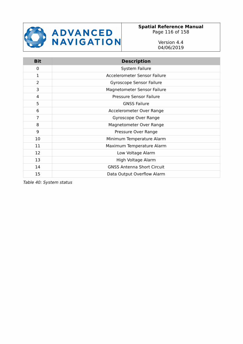
Spatial Reference ManualPage 116 of 158
Version 4.404/06/2019
Bit Description
0 System Failure
1 Accelerometer Sensor Failure
2 Gyroscope Sensor Failure
3 Magnetometer Sensor Failure
4 Pressure Sensor Failure
5 GNSS Failure
6 Accelerometer Over Range
7 Gyroscope Over Range
8 Magnetometer Over Range
9 Pressure Over Range
10 Minimum Temperature Alarm
11 Maximum Temperature Alarm
12 Low Voltage Alarm
13 High Voltage Alarm
14 GNSS Antenna Short Circuit
15 Data Output Overflow Alarm
Table 40: System status
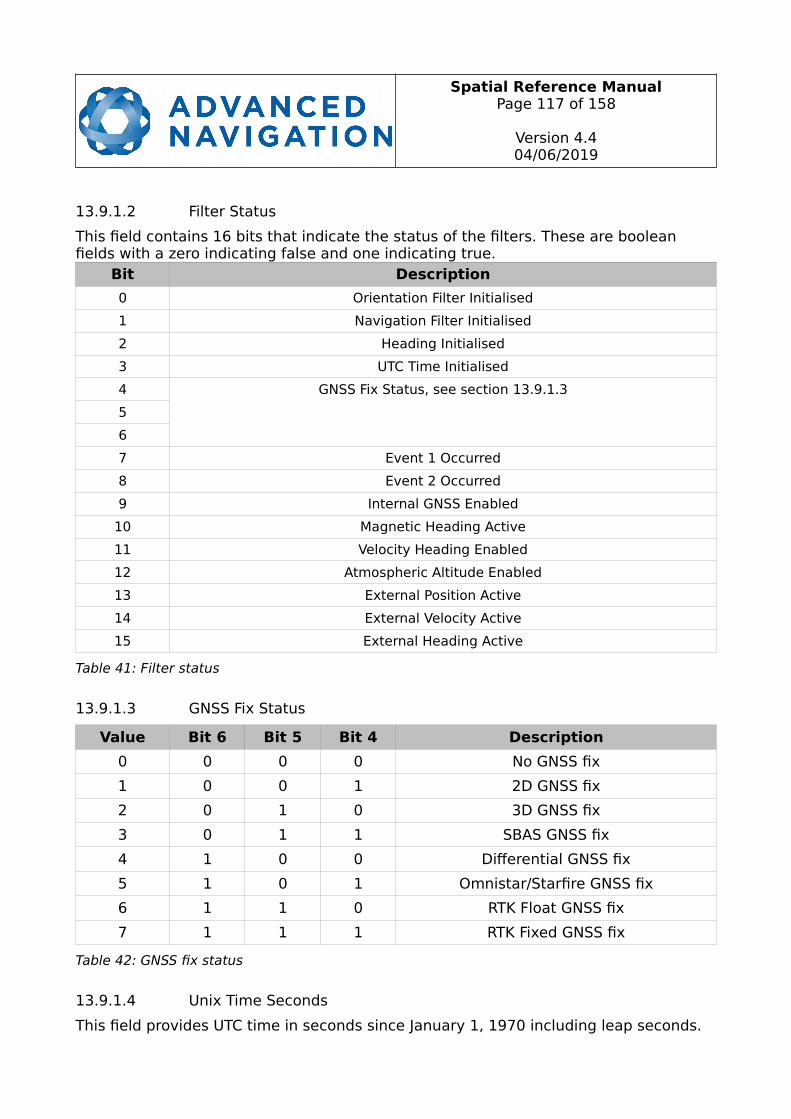
Spatial Reference ManualPage 117 of 158
Version 4.404/06/2019
13.9.1.2 Filter Status
This field contains 16 bits that indicate the status of the filters. These are boolean fields with a zero indicating false and one indicating true.
Bit Description
0 Orientation Filter Initialised
1 Navigation Filter Initialised
2 Heading Initialised
3 UTC Time Initialised
4 GNSS Fix Status, see section 13.9.1.3
5
6
7 Event 1 Occurred
8 Event 2 Occurred
9 Internal GNSS Enabled
10 Magnetic Heading Active
11 Velocity Heading Enabled
12 Atmospheric Altitude Enabled
13 External Position Active
14 External Velocity Active
15 External Heading Active
Table 41: Filter status
13.9.1.3 GNSS Fix Status
Value Bit 6 Bit 5 Bit 4 Description
0 0 0 0 No GNSS fix
1 0 0 1 2D GNSS fix
2 0 1 0 3D GNSS fix
3 0 1 1 SBAS GNSS fix
4 1 0 0 Differential GNSS fix
5 1 0 1 Omnistar/Starfire GNSS fix
6 1 1 0 RTK Float GNSS fix
7 1 1 1 RTK Fixed GNSS fix
Table 42: GNSS fix status
13.9.1.4 Unix Time Seconds
This field provides UTC time in seconds since January 1, 1970 including leap seconds.

Spatial Reference ManualPage 118 of 158
Version 4.404/06/2019
13.9.1.5 Microseconds
This field provides the sub-second component of time. It is represented as microseconds since the last second. Minimum value is 0 and maximum value is 999999.
13.9.2 Unix Time Packet
Unix Time Packet
Packet ID 21
Length 8
Field#
BytesOffset
DataType
Size Description
1 0 u32 4 Unix time (seconds), see section 13.9.1.4
2 4 u32 4 Microseconds, see section 13.9.1.5
Table 43: Unix time packet
13.9.3 Formatted Time Packet
Formatted Time Packet
Packet ID 22
Length 14
Field#
BytesOffset
DataType
Size Description
1 0 u32 4 Microseconds
2 4 u16 2 Year
3 6 u16 2 Year day, 0 - 365
4 8 u8 1 Month, 0 - 11
5 9 u8 1 Month Day, 1 - 31
6 10 u8 1 Week Day, 0 - 6
7 11 u8 1 Hour, 0 - 23
8 12 u8 1 Minute, 0 - 59
9 13 u8 1 Second, 0 - 59
Table 44: Formatted time packet

Spatial Reference ManualPage 119 of 158
Version 4.404/06/2019
13.9.4 Status Packet
Status Packet
Packet ID 23
Length 4
Field#
BytesOffset
DataType
Size Description
1 0 u16 2 System status, see section 13.9.1.1
2 2 u16 2 Filter status, see section 13.9.1.2
Table 45: Status packet
13.9.5 Position Standard Deviation Packet
Position Standard Deviation Packet
Packet ID 24
Length 12
Field#
BytesOffset
DataType
Size Description
1 0 fp32 4 Latitude standard deviation (m)
2 4 fp32 4 Longitude standard deviation (m)
3 8 fp32 4 Height standard deviation (m)
Table 46: Position standard deviation packet
13.9.6 Velocity Standard Deviation Packet
Velocity Standard Deviation Packet
Packet ID 25
Length 12
Field#
BytesOffset
DataType
Size Description
1 0 fp32 4 Velocity north standard deviation (m/s)
2 4 fp32 4 Velocity east standard deviation (m/s)
3 8 fp32 4 Velocity down standard deviation (m/s)
Table 47: Velocity standard deviation packet
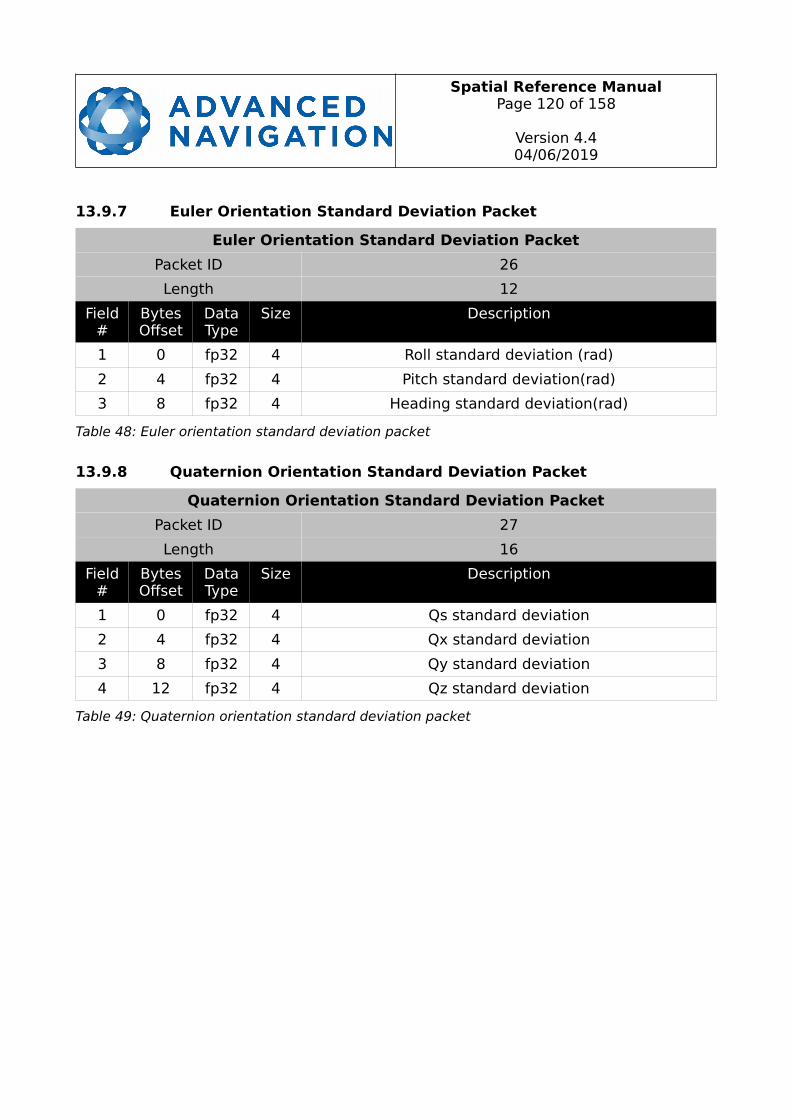
Spatial Reference ManualPage 120 of 158
Version 4.404/06/2019
13.9.7 Euler Orientation Standard Deviation Packet
Euler Orientation Standard Deviation Packet
Packet ID 26
Length 12
Field#
BytesOffset
DataType
Size Description
1 0 fp32 4 Roll standard deviation (rad)
2 4 fp32 4 Pitch standard deviation(rad)
3 8 fp32 4 Heading standard deviation(rad)
Table 48: Euler orientation standard deviation packet
13.9.8 Quaternion Orientation Standard Deviation Packet
Quaternion Orientation Standard Deviation Packet
Packet ID 27
Length 16
Field#
BytesOffset
DataType
Size Description
1 0 fp32 4 Qs standard deviation
2 4 fp32 4 Qx standard deviation
3 8 fp32 4 Qy standard deviation
4 12 fp32 4 Qz standard deviation
Table 49: Quaternion orientation standard deviation packet
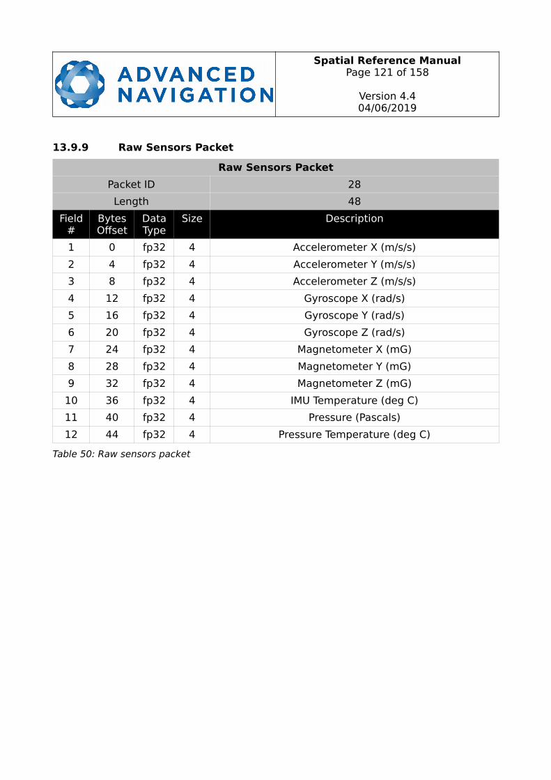
Spatial Reference ManualPage 121 of 158
Version 4.404/06/2019
13.9.9 Raw Sensors Packet
Raw Sensors Packet
Packet ID 28
Length 48
Field#
BytesOffset
DataType
Size Description
1 0 fp32 4 Accelerometer X (m/s/s)
2 4 fp32 4 Accelerometer Y (m/s/s)
3 8 fp32 4 Accelerometer Z (m/s/s)
4 12 fp32 4 Gyroscope X (rad/s)
5 16 fp32 4 Gyroscope Y (rad/s)
6 20 fp32 4 Gyroscope Z (rad/s)
7 24 fp32 4 Magnetometer X (mG)
8 28 fp32 4 Magnetometer Y (mG)
9 32 fp32 4 Magnetometer Z (mG)
10 36 fp32 4 IMU Temperature (deg C)
11 40 fp32 4 Pressure (Pascals)
12 44 fp32 4 Pressure Temperature (deg C)
Table 50: Raw sensors packet
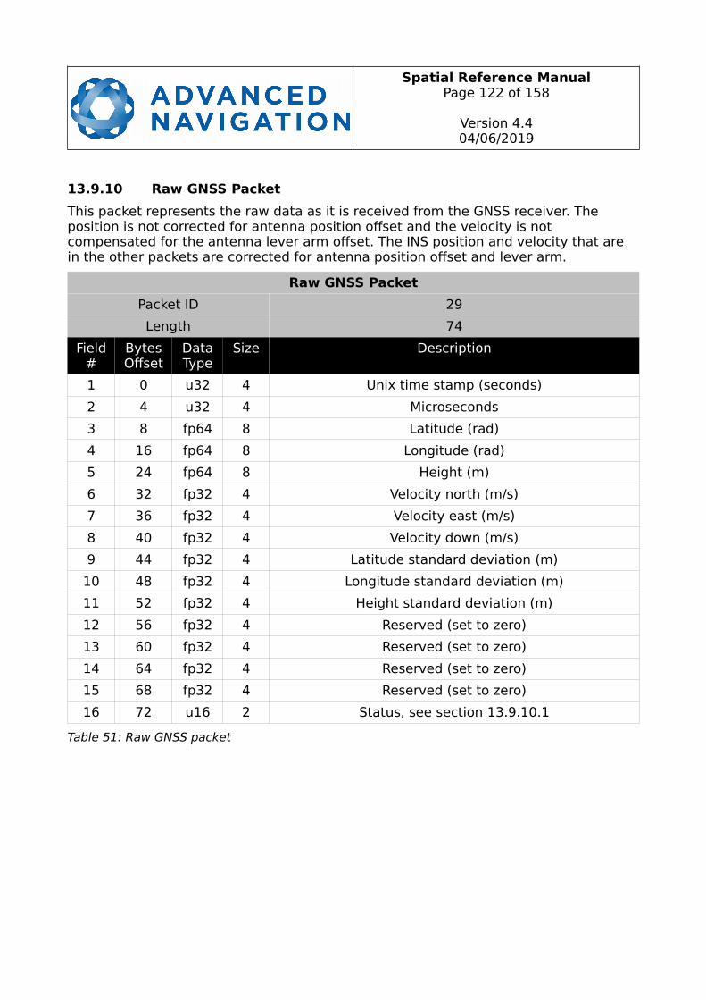
Spatial Reference ManualPage 122 of 158
Version 4.404/06/2019
13.9.10 Raw GNSS Packet
This packet represents the raw data as it is received from the GNSS receiver. The position is not corrected for antenna position offset and the velocity is not compensated for the antenna lever arm offset. The INS position and velocity that are in the other packets are corrected for antenna position offset and lever arm.
Raw GNSS Packet
Packet ID 29
Length 74
Field#
BytesOffset
DataType
Size Description
1 0 u32 4 Unix time stamp (seconds)
2 4 u32 4 Microseconds
3 8 fp64 8 Latitude (rad)
4 16 fp64 8 Longitude (rad)
5 24 fp64 8 Height (m)
6 32 fp32 4 Velocity north (m/s)
7 36 fp32 4 Velocity east (m/s)
8 40 fp32 4 Velocity down (m/s)
9 44 fp32 4 Latitude standard deviation (m)
10 48 fp32 4 Longitude standard deviation (m)
11 52 fp32 4 Height standard deviation (m)
12 56 fp32 4 Reserved (set to zero)
13 60 fp32 4 Reserved (set to zero)
14 64 fp32 4 Reserved (set to zero)
15 68 fp32 4 Reserved (set to zero)
16 72 u16 2 Status, see section 13.9.10.1
Table 51: Raw GNSS packet
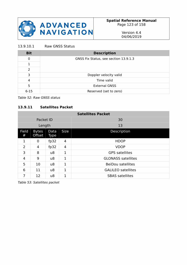
Spatial Reference ManualPage 123 of 158
Version 4.404/06/2019
13.9.10.1 Raw GNSS Status
Bit Description
0 GNSS Fix Status, see section 13.9.1.3
1
2
3 Doppler velocity valid
4 Time valid
5 External GNSS
6-15 Reserved (set to zero)
Table 52: Raw GNSS status
13.9.11 Satellites Packet
Satellites Packet
Packet ID 30
Length 13
Field#
BytesOffset
DataType
Size Description
1 0 fp32 4 HDOP
2 4 fp32 4 VDOP
3 8 u8 1 GPS satellites
4 9 u8 1 GLONASS satellites
5 10 u8 1 BeiDou satellites
6 11 u8 1 GALILEO satellites
7 12 u8 1 SBAS satellites
Table 53: Satellites packet
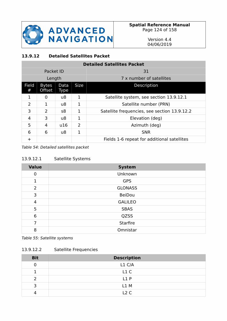
Spatial Reference ManualPage 124 of 158
Version 4.404/06/2019
13.9.12 Detailed Satellites Packet
Detailed Satellites Packet
Packet ID 31
Length 7 x number of satellites
Field#
BytesOffset
DataType
Size Description
1 0 u8 1 Satellite system, see section 13.9.12.1
2 1 u8 1 Satellite number (PRN)
3 2 s8 1 Satellite frequencies, see section 13.9.12.2
4 3 u8 1 Elevation (deg)
5 4 u16 2 Azimuth (deg)
6 6 u8 1 SNR
+ Fields 1-6 repeat for additional satellites
Table 54: Detailed satellites packet
13.9.12.1 Satellite Systems
Value System
0 Unknown
1 GPS
2 GLONASS
3 BeiDou
4 GALILEO
5 SBAS
6 QZSS
7 Starfire
8 Omnistar
Table 55: Satellite systems
13.9.12.2 Satellite Frequencies
Bit Description
0 L1 C/A
1 L1 C
2 L1 P
3 L1 M
4 L2 C

Spatial Reference ManualPage 125 of 158
Version 4.404/06/2019
5 L2 P
6 L2 M
7 L5
Table 56: Satellite frequencies
13.9.13 Geodetic Position Packet
Geodetic Position Packet
Packet ID 32
Length 24
Field#
BytesOffset
DataType
Size Description
1 0 fp64 8 Latitude (rad)
2 8 fp64 8 Longitude (rad)
3 16 fp64 8 Height (m)
Table 57: Geodetic position packet
13.9.14 ECEF Position Packet
ECEF Position Packet
Packet ID 33
Length 24
Field#
BytesOffset
DataType
Size Description
1 0 fp64 8 ECEF X (m)
2 8 fp64 8 ECEF Y (m)
3 16 fp64 8 ECEF Z (m)
Table 58: ECEF position packet

Spatial Reference ManualPage 126 of 158
Version 4.404/06/2019
13.9.15 UTM Position Packet
UTM Position Packet
Packet ID 34
Length 26
Field#
BytesOffset
DataType
Size Description
1 0 fp64 8 Northing (m)
2 8 fp64 8 Easting (m)
3 16 fp64 8 Height (m)
4 24 u8 1 Zone number
5 25 s8 1 Zone character
Table 59: UTM position packet
13.9.16 NED Velocity Packet
NED Velocity Packet
Packet ID 35
Length 12
Field#
BytesOffset
DataType
Size Description
1 0 fp32 4 Velocity north (m/s)
2 4 fp32 4 Velocity east (m/s)
3 8 fp32 4 Velocity down (m/s)
Table 60: NED velocity packet
13.9.17 Body Velocity Packet
Body Velocity Packet
Packet ID 36
Length 12
Field#
BytesOffset
DataType
Size Description
1 0 fp32 4 Velocity X (m/s)
2 4 fp32 4 Velocity Y (m/s)
3 8 fp32 4 Velocity Z (m/s)
Table 61: Body velocity packet
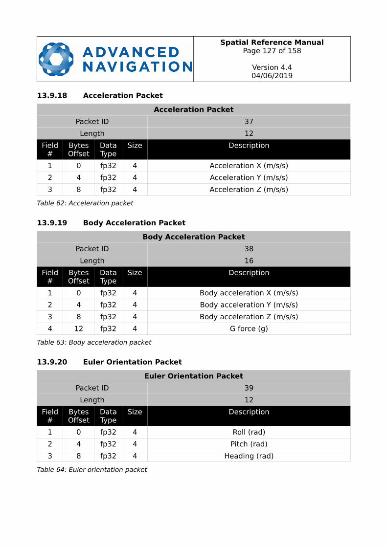
Spatial Reference ManualPage 127 of 158
Version 4.404/06/2019
13.9.18 Acceleration Packet
Acceleration Packet
Packet ID 37
Length 12
Field#
BytesOffset
DataType
Size Description
1 0 fp32 4 Acceleration X (m/s/s)
2 4 fp32 4 Acceleration Y (m/s/s)
3 8 fp32 4 Acceleration Z (m/s/s)
Table 62: Acceleration packet
13.9.19 Body Acceleration Packet
Body Acceleration Packet
Packet ID 38
Length 16
Field#
BytesOffset
DataType
Size Description
1 0 fp32 4 Body acceleration X (m/s/s)
2 4 fp32 4 Body acceleration Y (m/s/s)
3 8 fp32 4 Body acceleration Z (m/s/s)
4 12 fp32 4 G force (g)
Table 63: Body acceleration packet
13.9.20 Euler Orientation Packet
Euler Orientation Packet
Packet ID 39
Length 12
Field#
BytesOffset
DataType
Size Description
1 0 fp32 4 Roll (rad)
2 4 fp32 4 Pitch (rad)
3 8 fp32 4 Heading (rad)
Table 64: Euler orientation packet

Spatial Reference ManualPage 128 of 158
Version 4.404/06/2019
13.9.21 Quaternion Orientation Packet
Quaternion Orientation Packet
Packet ID 40
Length 16
Field#
BytesOffset
DataType
Size Description
1 0 fp32 4 Qs
2 4 fp32 4 Qx
3 8 fp32 4 Qy
4 12 fp32 4 Qz
Table 65: Quaternion orientation packet
13.9.22 DCM Orientation Packet
DCM Orientation Packet
Packet ID 41
Length 36
Field#
BytesOffset
DataType
Size Description
1 0 fp32 4 DCM[0][0]
2 4 fp32 4 DCM[0][1]
3 8 fp32 4 DCM[0][2]
4 12 fp32 4 DCM[1][0]
5 16 fp32 4 DCM[1][1]
6 20 fp32 4 DCM[1][2]
7 24 fp32 4 DCM[2][0]
8 28 fp32 4 DCM[2][1]
9 32 fp32 4 DCM[2][2]
Table 66: DCM orientation packet
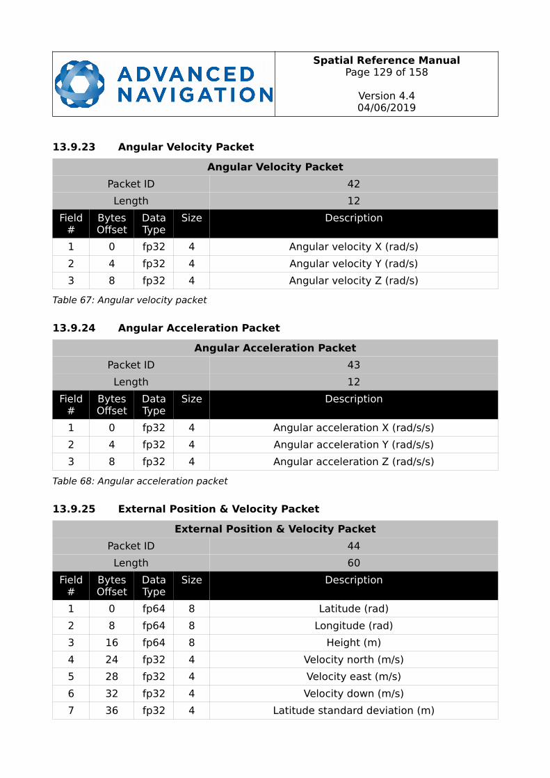
Spatial Reference ManualPage 129 of 158
Version 4.404/06/2019
13.9.23 Angular Velocity Packet
Angular Velocity Packet
Packet ID 42
Length 12
Field#
BytesOffset
DataType
Size Description
1 0 fp32 4 Angular velocity X (rad/s)
2 4 fp32 4 Angular velocity Y (rad/s)
3 8 fp32 4 Angular velocity Z (rad/s)
Table 67: Angular velocity packet
13.9.24 Angular Acceleration Packet
Angular Acceleration Packet
Packet ID 43
Length 12
Field#
BytesOffset
DataType
Size Description
1 0 fp32 4 Angular acceleration X (rad/s/s)
2 4 fp32 4 Angular acceleration Y (rad/s/s)
3 8 fp32 4 Angular acceleration Z (rad/s/s)
Table 68: Angular acceleration packet
13.9.25 External Position & Velocity Packet
External Position & Velocity Packet
Packet ID 44
Length 60
Field#
BytesOffset
DataType
Size Description
1 0 fp64 8 Latitude (rad)
2 8 fp64 8 Longitude (rad)
3 16 fp64 8 Height (m)
4 24 fp32 4 Velocity north (m/s)
5 28 fp32 4 Velocity east (m/s)
6 32 fp32 4 Velocity down (m/s)
7 36 fp32 4 Latitude standard deviation (m)
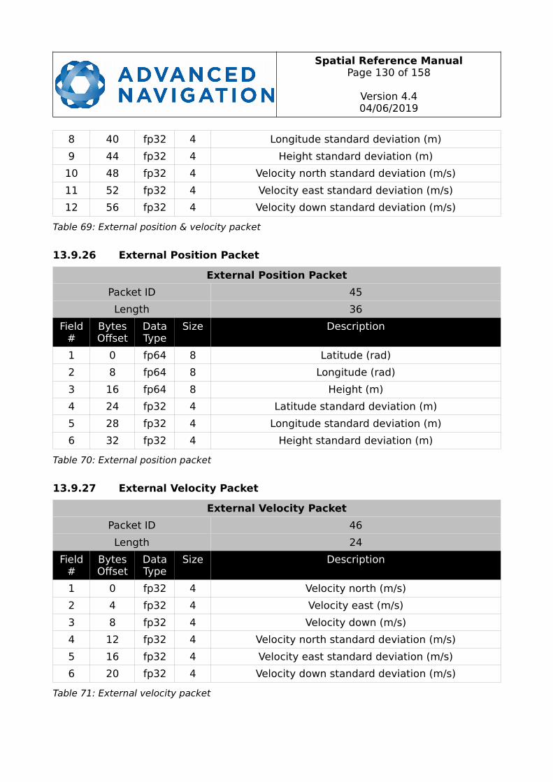
Spatial Reference ManualPage 130 of 158
Version 4.404/06/2019
8 40 fp32 4 Longitude standard deviation (m)
9 44 fp32 4 Height standard deviation (m)
10 48 fp32 4 Velocity north standard deviation (m/s)
11 52 fp32 4 Velocity east standard deviation (m/s)
12 56 fp32 4 Velocity down standard deviation (m/s)
Table 69: External position & velocity packet
13.9.26 External Position Packet
External Position Packet
Packet ID 45
Length 36
Field#
BytesOffset
DataType
Size Description
1 0 fp64 8 Latitude (rad)
2 8 fp64 8 Longitude (rad)
3 16 fp64 8 Height (m)
4 24 fp32 4 Latitude standard deviation (m)
5 28 fp32 4 Longitude standard deviation (m)
6 32 fp32 4 Height standard deviation (m)
Table 70: External position packet
13.9.27 External Velocity Packet
External Velocity Packet
Packet ID 46
Length 24
Field#
BytesOffset
DataType
Size Description
1 0 fp32 4 Velocity north (m/s)
2 4 fp32 4 Velocity east (m/s)
3 8 fp32 4 Velocity down (m/s)
4 12 fp32 4 Velocity north standard deviation (m/s)
5 16 fp32 4 Velocity east standard deviation (m/s)
6 20 fp32 4 Velocity down standard deviation (m/s)
Table 71: External velocity packet
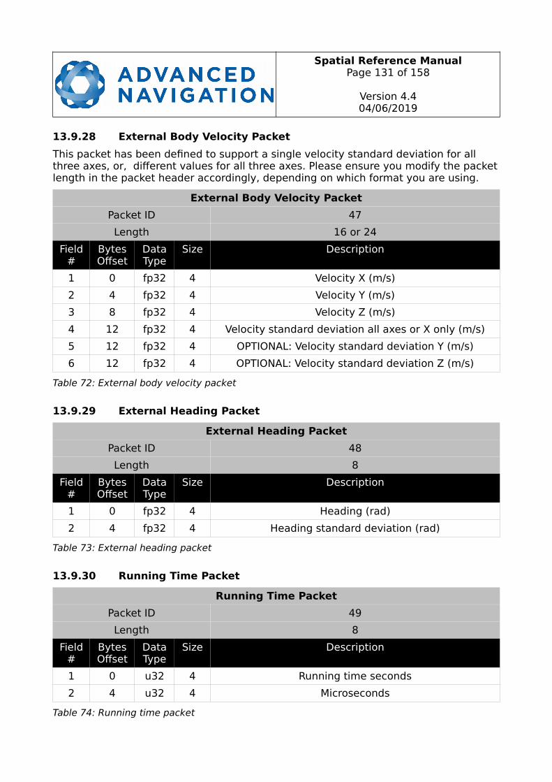
Spatial Reference ManualPage 131 of 158
Version 4.404/06/2019
13.9.28 External Body Velocity Packet
This packet has been defined to support a single velocity standard deviation for all three axes, or, different values for all three axes. Please ensure you modify the packetlength in the packet header accordingly, depending on which format you are using.
External Body Velocity Packet
Packet ID 47
Length 16 or 24
Field#
BytesOffset
DataType
Size Description
1 0 fp32 4 Velocity X (m/s)
2 4 fp32 4 Velocity Y (m/s)
3 8 fp32 4 Velocity Z (m/s)
4 12 fp32 4 Velocity standard deviation all axes or X only (m/s)
5 12 fp32 4 OPTIONAL: Velocity standard deviation Y (m/s)
6 12 fp32 4 OPTIONAL: Velocity standard deviation Z (m/s)
Table 72: External body velocity packet
13.9.29 External Heading Packet
External Heading Packet
Packet ID 48
Length 8
Field#
BytesOffset
DataType
Size Description
1 0 fp32 4 Heading (rad)
2 4 fp32 4 Heading standard deviation (rad)
Table 73: External heading packet
13.9.30 Running Time Packet
Running Time Packet
Packet ID 49
Length 8
Field#
BytesOffset
DataType
Size Description
1 0 u32 4 Running time seconds
2 4 u32 4 Microseconds
Table 74: Running time packet
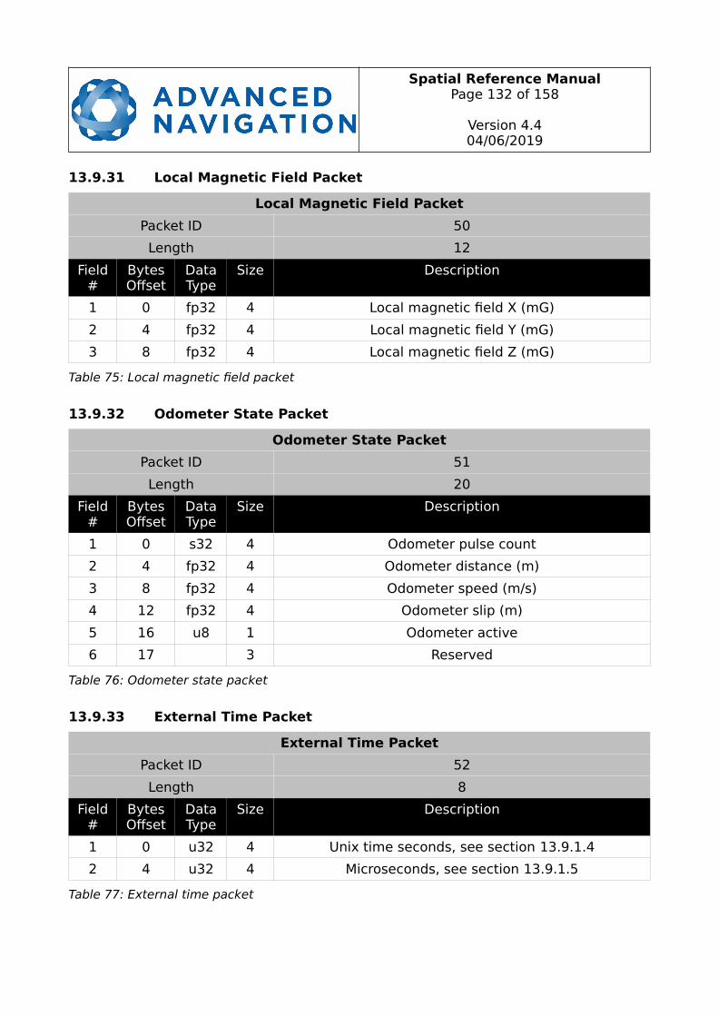
Spatial Reference ManualPage 132 of 158
Version 4.404/06/2019
13.9.31 Local Magnetic Field Packet
Local Magnetic Field Packet
Packet ID 50
Length 12
Field#
BytesOffset
DataType
Size Description
1 0 fp32 4 Local magnetic field X (mG)
2 4 fp32 4 Local magnetic field Y (mG)
3 8 fp32 4 Local magnetic field Z (mG)
Table 75: Local magnetic field packet
13.9.32 Odometer State Packet
Odometer State Packet
Packet ID 51
Length 20
Field#
BytesOffset
DataType
Size Description
1 0 s32 4 Odometer pulse count
2 4 fp32 4 Odometer distance (m)
3 8 fp32 4 Odometer speed (m/s)
4 12 fp32 4 Odometer slip (m)
5 16 u8 1 Odometer active
6 17 3 Reserved
Table 76: Odometer state packet
13.9.33 External Time Packet
External Time Packet
Packet ID 52
Length 8
Field#
BytesOffset
DataType
Size Description
1 0 u32 4 Unix time seconds, see section 13.9.1.4
2 4 u32 4 Microseconds, see section 13.9.1.5
Table 77: External time packet
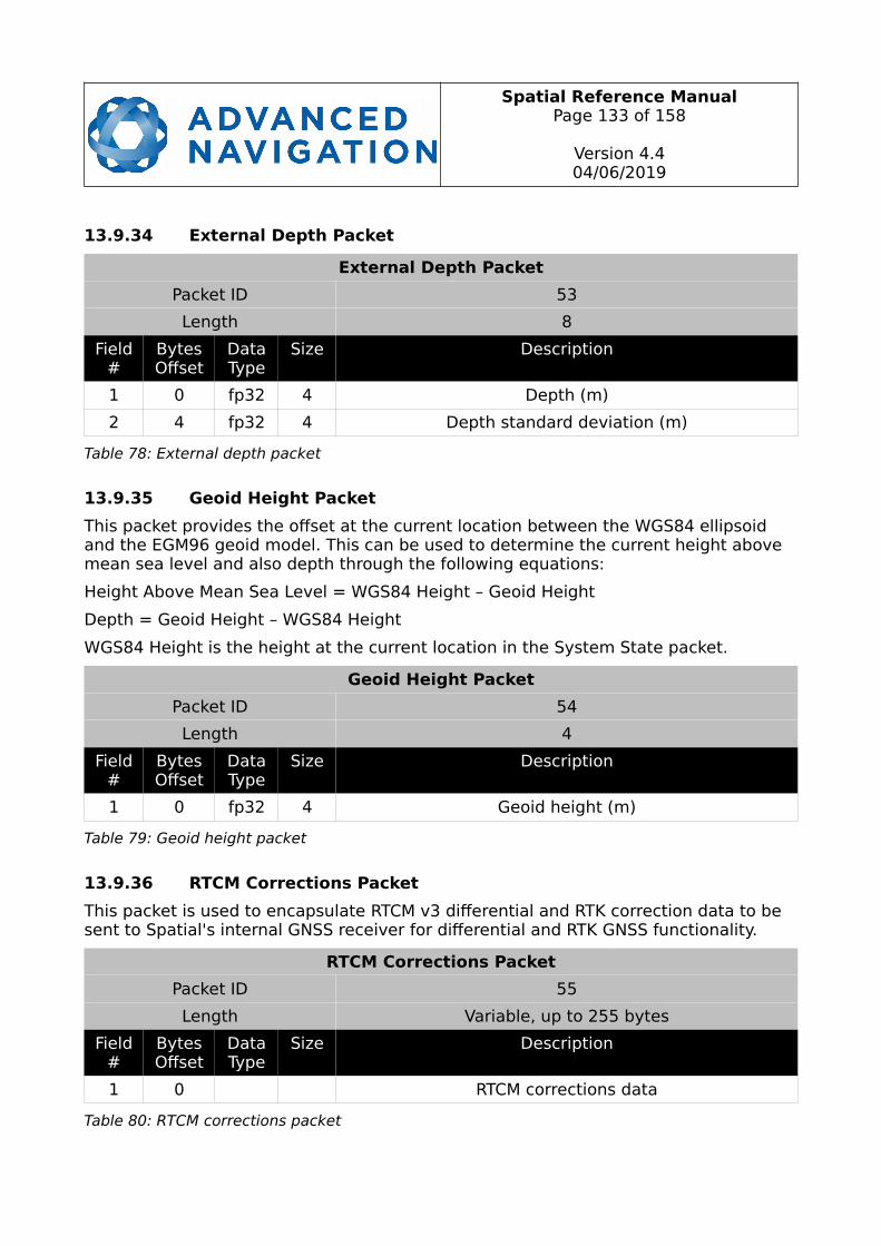
Spatial Reference ManualPage 133 of 158
Version 4.404/06/2019
13.9.34 External Depth Packet
External Depth Packet
Packet ID 53
Length 8
Field#
BytesOffset
DataType
Size Description
1 0 fp32 4 Depth (m)
2 4 fp32 4 Depth standard deviation (m)
Table 78: External depth packet
13.9.35 Geoid Height Packet
This packet provides the offset at the current location between the WGS84 ellipsoid and the EGM96 geoid model. This can be used to determine the current height above mean sea level and also depth through the following equations:
Height Above Mean Sea Level = WGS84 Height – Geoid Height
Depth = Geoid Height – WGS84 Height
WGS84 Height is the height at the current location in the System State packet.
Geoid Height Packet
Packet ID 54
Length 4
Field#
BytesOffset
DataType
Size Description
1 0 fp32 4 Geoid height (m)
Table 79: Geoid height packet
13.9.36 RTCM Corrections Packet
This packet is used to encapsulate RTCM v3 differential and RTK correction data to be sent to Spatial's internal GNSS receiver for differential and RTK GNSS functionality.
RTCM Corrections Packet
Packet ID 55
Length Variable, up to 255 bytes
Field#
BytesOffset
DataType
Size Description
1 0 RTCM corrections data
Table 80: RTCM corrections packet
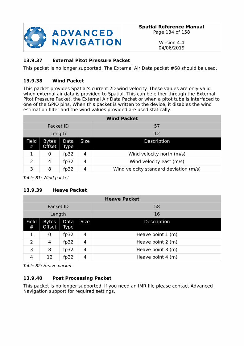
Spatial Reference ManualPage 134 of 158
Version 4.404/06/2019
13.9.37 External Pitot Pressure Packet
This packet is no longer supported. The External Air Data packet #68 should be used.
13.9.38 Wind Packet
This packet provides Spatial's current 2D wind velocity. These values are only valid when external air data is provided to Spatial. This can be either through the External Pitot Pressure Packet, the External Air Data Packet or when a pitot tube is interfaced toone of the GPIO pins. When this packet is written to the device, it disables the wind estimation filter and the wind values provided are used statically.
Wind Packet
Packet ID 57
Length 12
Field#
BytesOffset
DataType
Size Description
1 0 fp32 4 Wind velocity north (m/s)
2 4 fp32 4 Wind velocity east (m/s)
3 8 fp32 4 Wind velocity standard deviation (m/s)
Table 81: Wind packet
13.9.39 Heave Packet
Heave Packet
Packet ID 58
Length 16
Field#
BytesOffset
DataType
Size Description
1 0 fp32 4 Heave point 1 (m)
2 4 fp32 4 Heave point 2 (m)
3 8 fp32 4 Heave point 3 (m)
4 12 fp32 4 Heave point 4 (m)
Table 82: Heave packet
13.9.40 Post Processing Packet
This packet is no longer supported. If you need an IMR file please contact Advanced Navigation support for required settings.
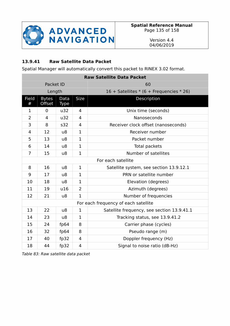
Spatial Reference ManualPage 135 of 158
Version 4.404/06/2019
13.9.41 Raw Satellite Data Packet
Spatial Manager will automatically convert this packet to RINEX 3.02 format.
Raw Satellite Data Packet
Packet ID 60
Length 16 + Satellites * (6 + Frequencies * 26)
Field#
BytesOffset
DataType
Size Description
1 0 u32 4 Unix time (seconds)
2 4 u32 4 Nanoseconds
3 8 s32 4 Receiver clock offset (nanoseconds)
4 12 u8 1 Receiver number
5 13 u8 1 Packet number
6 14 u8 1 Total packets
7 15 u8 1 Number of satellites
For each satellite
8 16 u8 1 Satellite system, see section 13.9.12.1
9 17 u8 1 PRN or satellite number
10 18 u8 1 Elevation (degrees)
11 19 u16 2 Azimuth (degrees)
12 21 u8 1 Number of frequencies
For each frequency of each satellite
13 22 u8 1 Satellite frequency, see section 13.9.41.1
14 23 u8 1 Tracking status, see 13.9.41.2
15 24 fp64 8 Carrier phase (cycles)
16 32 fp64 8 Pseudo range (m)
17 40 fp32 4 Doppler frequency (Hz)
18 44 fp32 4 Signal to noise ratio (dB-Hz)
Table 83: Raw satellite data packet

Spatial Reference ManualPage 136 of 158
Version 4.404/06/2019
13.9.41.1 Satellite Frequencies
Value GPS GLONASS Galileo BeiDou SBAS QZSS
0 Unknown Unknown Unknown Unknown Unknown Unknown
1 L1 C/A G1 C/A E1 OS B1 L1 C/A L1 C/A
2 L1 C E1 PRS L1 C
3 L1 P G1 P L1 SAIF
4 L1 M
5 L2 C G2 C/A E6 CS B2 L2 C
6 L2 P G2 P E6 PRS LEX
7 L2 M
8 L5 G3 E5 a B3 L5 L5
9 E5 b
10 E5 a+b
Table 84: Satellite frequencies
13.9.41.2 Tracking Status
Bit Description
0 Carrier phase valid
1 Carrier phase cycle slip detected
2 Carrier phase half-cycle ambiguity
3 Pseudo range valid
4 Doppler valid
5 SNR valid
6-7 Reserved (set to zero)
Table 85: Tracking status

Spatial Reference ManualPage 137 of 158
Version 4.404/06/2019
13.9.42 External Odometer Packet
External Odometer Packet
Packet ID 67
Length 13
Field#
BytesOffset
DataType
Size Description
1 0 fp32 4 Estimated delay (s)
2 4 fp32 4 Speed (m/s)
3 8 fp32 4 Reserved (set to zero)
3 12 u8 1 Odometer flags, see section 13.9.42.1
Table 86: External odometer packet
13.9.42.1 Odometer flags
Bit Description
0 Reversing detection supported
1-7 Reserved (set to zero)
Table 87: Odometer flags
13.9.43 External Air Data Packet
External Air Data Packet
Packet ID 68
Length 25
Field#
BytesOffset
DataType
Size Description
1 0 fp32 4 Barometric altitude delay (s)
2 4 fp32 4 Airspeed delay (s)
2 8 fp32 4 Barometric altitude (m)
3 12 fp32 4 Airspeed (m/s)
4 16 fp32 4 Barometric altitude standard deviation (m)
5 20 fp32 4 Airspeed standard deviation (m/s)
6 24 u8 1 Flags, see section 13.9.43.1
Table 88: External air data packet

Spatial Reference ManualPage 138 of 158
Version 4.404/06/2019
13.9.43.1 External Air Data Flags
Bit Description
0 Barometric altitude set and valid
1 Airspeed set and valid
2 Barometric altitude reference reset
Table 89: External air data flags
13.9.43.2 Notes
Barometric altitude does not need to be referenced to any co-ordinate frame or QNH. Ifthe barometric altitude reference is changed during operation, the barometric altitude reference reset flag should be set for the next packet.
13.9.44 Gimbal State Packet
Gimbal State Packet
Packet ID 72
Length 8
Field#
BytesOffset
DataType
Size Description
1 0 fp32 4 Current angle (rad)
2 4 4 Reserved (set to zero)
Table 90: Gimbal state packet
13.9.45 Automotive Packet
Automotive Packet
Packet ID 73
Length 24
Field#
BytesOffset
DataType
Size Description
1 0 fp32 4 Virtual odometer distance (m)
2 4 fp32 4 Slip Angle (rad)
3 8 fp32 4 Velocity X (m/s)
4 12 fp32 4 Velocity Y (m/s)
5 16 fp32 4 Distance standard deviation (m)
6 20 4 Reserved (set to zero)
Table 91: Automotive packet
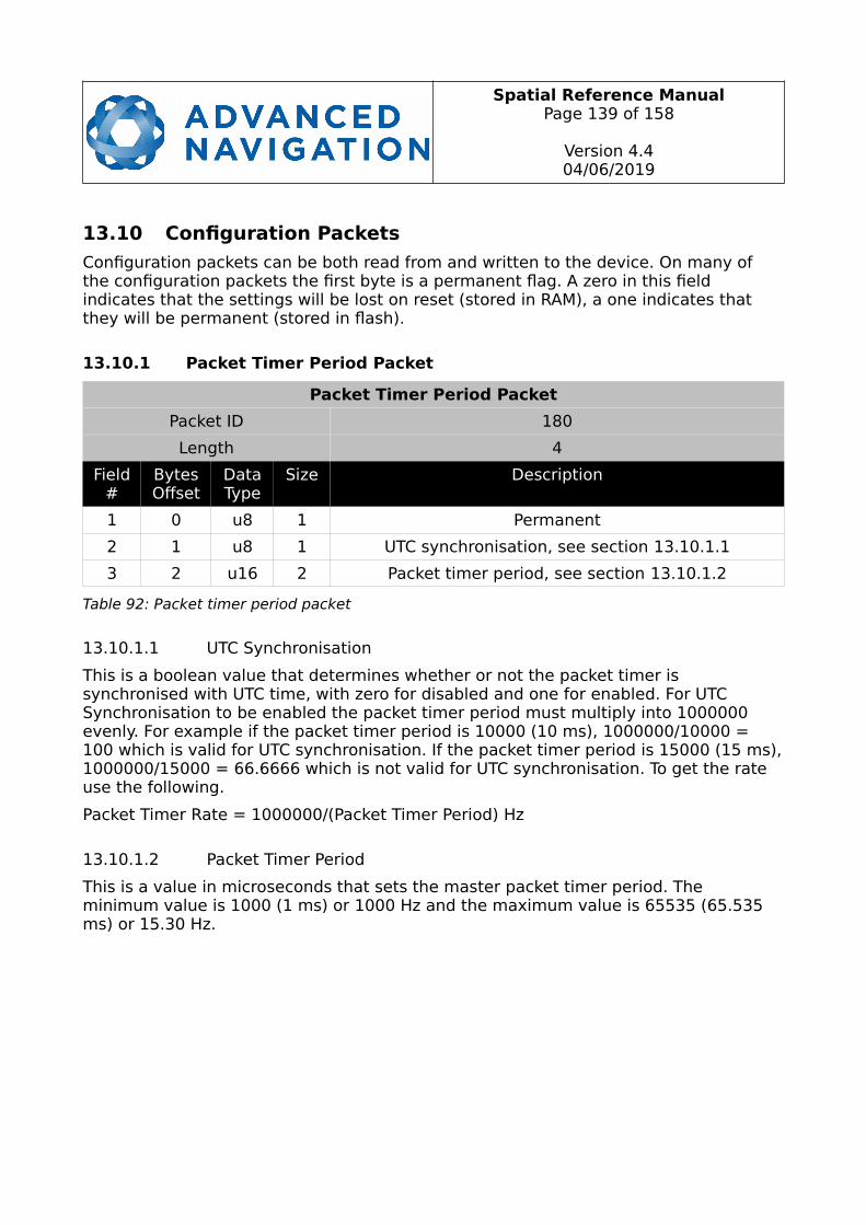
Spatial Reference ManualPage 139 of 158
Version 4.404/06/2019
13.10 Configuration Packets
Configuration packets can be both read from and written to the device. On many of the configuration packets the first byte is a permanent flag. A zero in this field indicates that the settings will be lost on reset (stored in RAM), a one indicates that they will be permanent (stored in flash).
13.10.1 Packet Timer Period Packet
Packet Timer Period Packet
Packet ID 180
Length 4
Field#
BytesOffset
DataType
Size Description
1 0 u8 1 Permanent
2 1 u8 1 UTC synchronisation, see section 13.10.1.1
3 2 u16 2 Packet timer period, see section 13.10.1.2
Table 92: Packet timer period packet
13.10.1.1 UTC Synchronisation
This is a boolean value that determines whether or not the packet timer is synchronised with UTC time, with zero for disabled and one for enabled. For UTC Synchronisation to be enabled the packet timer period must multiply into 1000000 evenly. For example if the packet timer period is 10000 (10 ms), 1000000/10000 = 100 which is valid for UTC synchronisation. If the packet timer period is 15000 (15 ms),1000000/15000 = 66.6666 which is not valid for UTC synchronisation. To get the rate use the following.
Packet Timer Rate = 1000000/(Packet Timer Period) Hz
13.10.1.2 Packet Timer Period
This is a value in microseconds that sets the master packet timer period. The minimum value is 1000 (1 ms) or 1000 Hz and the maximum value is 65535 (65.535 ms) or 15.30 Hz.
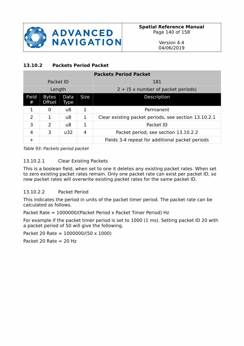
Spatial Reference ManualPage 140 of 158
Version 4.404/06/2019
13.10.2 Packets Period Packet
Packets Period Packet
Packet ID 181
Length 2 + (5 x number of packet periods)
Field#
BytesOffset
DataType
Size Description
1 0 u8 1 Permanent
2 1 u8 1 Clear existing packet periods, see section 13.10.2.1
3 2 u8 1 Packet ID
4 3 u32 4 Packet period, see section 13.10.2.2
+ Fields 3-4 repeat for additional packet periods
Table 93: Packets period packet
13.10.2.1 Clear Existing Packets
This is a boolean field, when set to one it deletes any existing packet rates. When set to zero existing packet rates remain. Only one packet rate can exist per packet ID, so new packet rates will overwrite existing packet rates for the same packet ID.
13.10.2.2 Packet Period
This indicates the period in units of the packet timer period. The packet rate can be calculated as follows.
Packet Rate = 1000000/(Packet Period x Packet Timer Period) Hz
For example if the packet timer period is set to 1000 (1 ms). Setting packet ID 20 with a packet period of 50 will give the following.
Packet 20 Rate = 1000000/(50 x 1000)
Packet 20 Rate = 20 Hz

Spatial Reference ManualPage 141 of 158
Version 4.404/06/2019
13.10.3 Baud Rates Packet
Baud Rates Packet
Packet ID 182
Length 17
Field#
BytesOffset
DataType
Size Description
1 0 u8 1 Permanent
2 1 u32 4 Primary RS232 and RS422 baud rate (2400 to2000000)
3 5 u32 4 GPIO 1 & 2 baud rate (2400 to 250000)
4 9 u32 4 Auxiliary RS232 Baud Rate (2400 to 2000000)
5 13 4 Reserved (set to zero)
Table 94: Baud rates packet
13.10.4 Sensor Ranges Packet
Sensor Ranges Packet
Packet ID 184
Length 4
Field#
BytesOffset
DataType
Size Description
1 0 u8 1 Permanent
2 1 u8 1 Accelerometers range, see section 13.10.4.1
3 2 u8 1 Gyroscopes range, see section 13.10.4.2
4 3 u8 1 Magnetometers range, see section 13.10.4.3
Table 95: Sensor ranges packet
13.10.4.1 Accelerometers Range
Value Description
0 2 g (19.62 m/s/s)
1 4 g (39.24 m/s/s)
2 16 g (156.96 m/s/s)
Table 96: Accelerometers range
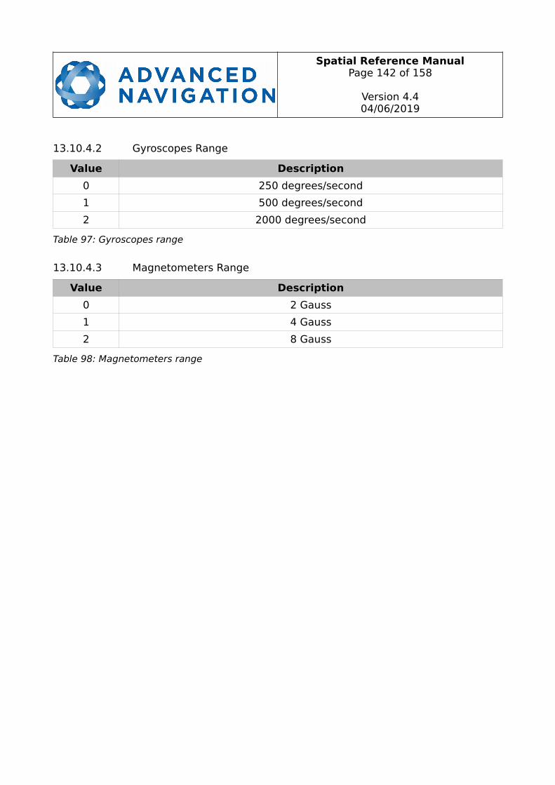
Spatial Reference ManualPage 142 of 158
Version 4.404/06/2019
13.10.4.2 Gyroscopes Range
Value Description
0 250 degrees/second
1 500 degrees/second
2 2000 degrees/second
Table 97: Gyroscopes range
13.10.4.3 Magnetometers Range
Value Description
0 2 Gauss
1 4 Gauss
2 8 Gauss
Table 98: Magnetometers range
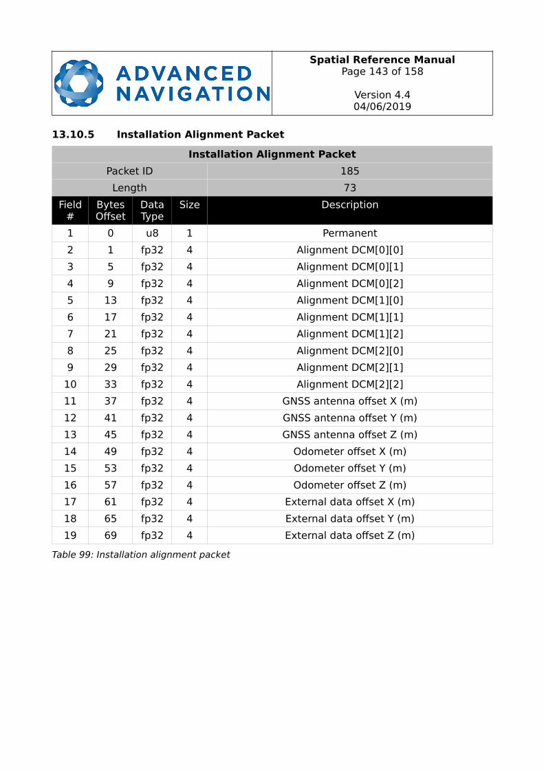
Spatial Reference ManualPage 143 of 158
Version 4.404/06/2019
13.10.5 Installation Alignment Packet
Installation Alignment Packet
Packet ID 185
Length 73
Field#
BytesOffset
DataType
Size Description
1 0 u8 1 Permanent
2 1 fp32 4 Alignment DCM[0][0]
3 5 fp32 4 Alignment DCM[0][1]
4 9 fp32 4 Alignment DCM[0][2]
5 13 fp32 4 Alignment DCM[1][0]
6 17 fp32 4 Alignment DCM[1][1]
7 21 fp32 4 Alignment DCM[1][2]
8 25 fp32 4 Alignment DCM[2][0]
9 29 fp32 4 Alignment DCM[2][1]
10 33 fp32 4 Alignment DCM[2][2]
11 37 fp32 4 GNSS antenna offset X (m)
12 41 fp32 4 GNSS antenna offset Y (m)
13 45 fp32 4 GNSS antenna offset Z (m)
14 49 fp32 4 Odometer offset X (m)
15 53 fp32 4 Odometer offset Y (m)
16 57 fp32 4 Odometer offset Z (m)
17 61 fp32 4 External data offset X (m)
18 65 fp32 4 External data offset Y (m)
19 69 fp32 4 External data offset Z (m)
Table 99: Installation alignment packet
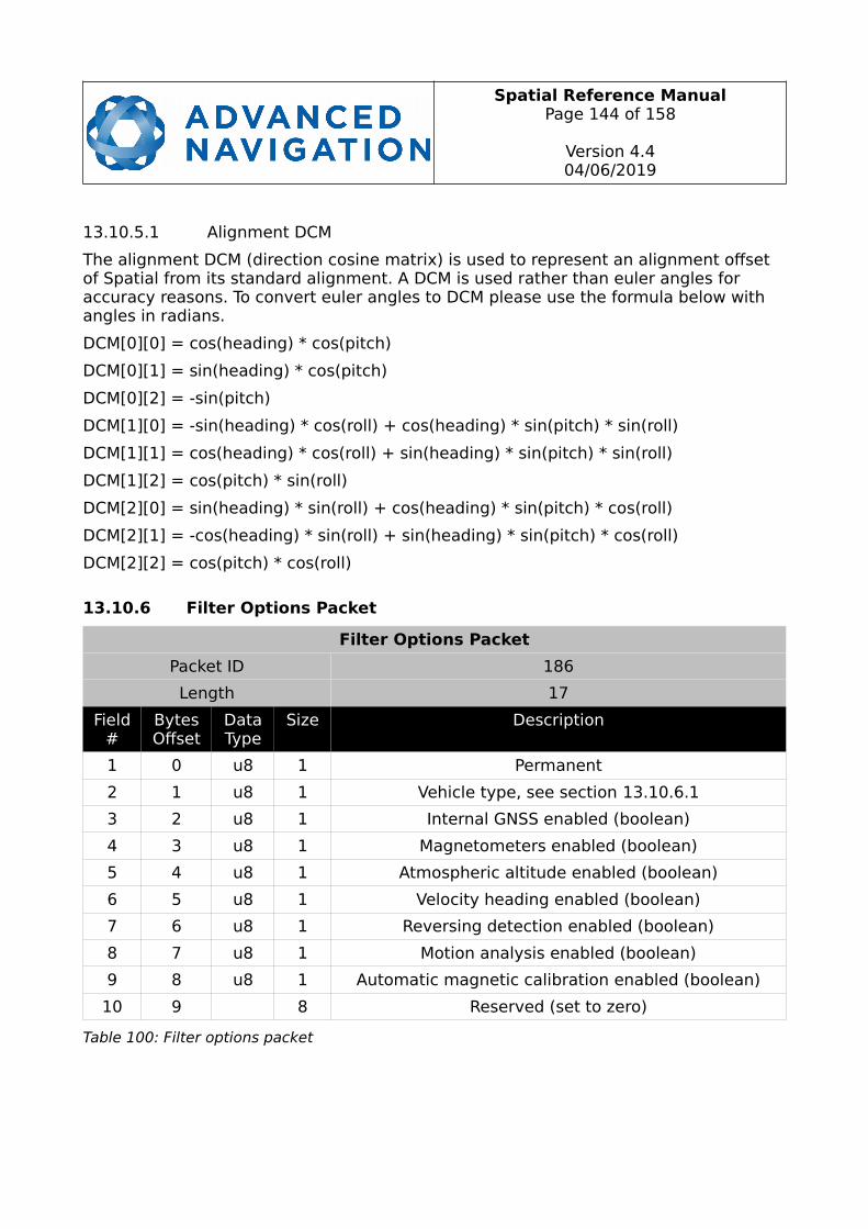
Spatial Reference ManualPage 144 of 158
Version 4.404/06/2019
13.10.5.1 Alignment DCM
The alignment DCM (direction cosine matrix) is used to represent an alignment offset of Spatial from its standard alignment. A DCM is used rather than euler angles for accuracy reasons. To convert euler angles to DCM please use the formula below with angles in radians.
DCM[0][0] = cos(heading) * cos(pitch)
DCM[0][1] = sin(heading) * cos(pitch)
DCM[0][2] = -sin(pitch)
DCM[1][0] = -sin(heading) * cos(roll) + cos(heading) * sin(pitch) * sin(roll)
DCM[1][1] = cos(heading) * cos(roll) + sin(heading) * sin(pitch) * sin(roll)
DCM[1][2] = cos(pitch) * sin(roll)
DCM[2][0] = sin(heading) * sin(roll) + cos(heading) * sin(pitch) * cos(roll)
DCM[2][1] = -cos(heading) * sin(roll) + sin(heading) * sin(pitch) * cos(roll)
DCM[2][2] = cos(pitch) * cos(roll)
13.10.6 Filter Options Packet
Filter Options Packet
Packet ID 186
Length 17
Field#
BytesOffset
DataType
Size Description
1 0 u8 1 Permanent
2 1 u8 1 Vehicle type, see section 13.10.6.1
3 2 u8 1 Internal GNSS enabled (boolean)
4 3 u8 1 Magnetometers enabled (boolean)
5 4 u8 1 Atmospheric altitude enabled (boolean)
6 5 u8 1 Velocity heading enabled (boolean)
7 6 u8 1 Reversing detection enabled (boolean)
8 7 u8 1 Motion analysis enabled (boolean)
9 8 u8 1 Automatic magnetic calibration enabled (boolean)
10 9 8 Reserved (set to zero)
Table 100: Filter options packet

Spatial Reference ManualPage 145 of 158
Version 4.404/06/2019
13.10.6.1 Vehicle Types
Value Description
0 Unconstrained
1 Bicycle or Motorcycle
2 Car
3 Hovercraft
4 Submarine
5 3D Underwater Vehicle
6 Fixed Wing Plane
7 3D Aircraft
8 Human
9 Boat
10 Large Ship
11 Stationary
12 Stunt Plane
13 Race Car
Table 101: Vehicle types
13.10.7 Advanced Filter Parameters Packet
This packet is no longer supported.
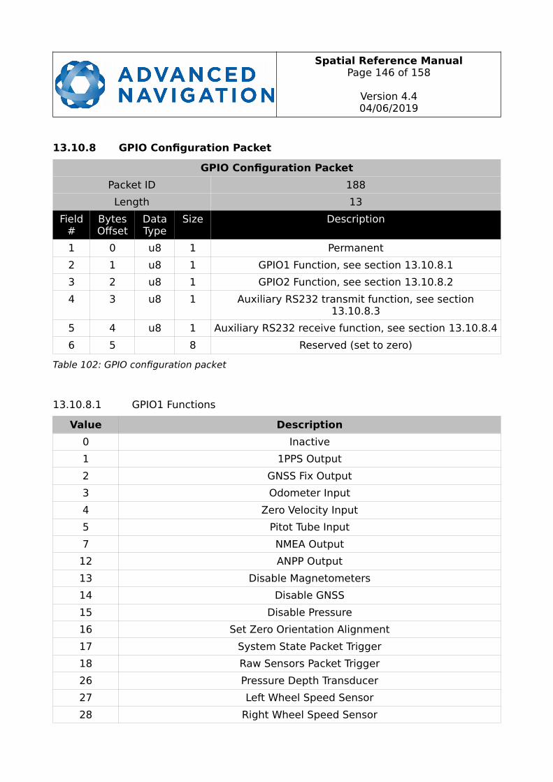
Spatial Reference ManualPage 146 of 158
Version 4.404/06/2019
13.10.8 GPIO Configuration Packet
GPIO Configuration Packet
Packet ID 188
Length 13
Field#
BytesOffset
DataType
Size Description
1 0 u8 1 Permanent
2 1 u8 1 GPIO1 Function, see section 13.10.8.1
3 2 u8 1 GPIO2 Function, see section 13.10.8.2
4 3 u8 1 Auxiliary RS232 transmit function, see section13.10.8.3
5 4 u8 1 Auxiliary RS232 receive function, see section 13.10.8.4
6 5 8 Reserved (set to zero)
Table 102: GPIO configuration packet
13.10.8.1 GPIO1 Functions
Value Description
0 Inactive
1 1PPS Output
2 GNSS Fix Output
3 Odometer Input
4 Zero Velocity Input
5 Pitot Tube Input
7 NMEA Output
12 ANPP Output
13 Disable Magnetometers
14 Disable GNSS
15 Disable Pressure
16 Set Zero Orientation Alignment
17 System State Packet Trigger
18 Raw Sensors Packet Trigger
26 Pressure Depth Transducer
27 Left Wheel Speed Sensor
28 Right Wheel Speed Sensor

Spatial Reference ManualPage 147 of 158
Version 4.404/06/2019
29 1PPS Input
30 Wheel Speed Sensor
31 Wheel Encoder Phase A
32 Wheel Encoder Phase B
33 Event 1 Input
34 Event 2 Input
38 GNSS Receiver Passthrough
39 TSS1 Output
40 Simrad 1000 Output
41 Simrad 3000 Output
42 Serial Port Passthrough
43 Gimbal Encoder Phase A
44 Gimbal Encoder Phase B
45 Odometer Direction, Forward Low
46 Odometer Direction, Forward High
53 Reverse Alignment, Forward Low
54 Reverse Alignment, Forward High
55 Zero Angular Velocity Input
Table 103: GPIO1 functions
13.10.8.2 GPIO2 Functions
Value Description
0 Inactive
1 1PPS Output
2 GNSS Fix Output
3 Odometer Input
4 Zero Velocity Input
5 Pitot Tube Input
6 NMEA Input
8 Novatel GNSS Input
9 Topcon GNSS Input
11 ANPP Input
13 Disable Magnetometers
14 Disable GNSS
15 Disable Pressure

Spatial Reference ManualPage 148 of 158
Version 4.404/06/2019
16 Set Zero Orientation Alignment
17 System State Packet Trigger
18 Raw Sensors Packet Trigger
19 RTCM Differential GNSS Corrections Input
20 Trimble GNSS Input
21 u-blox GNSS Input
22 Hemisphere GNSS Input
23 Teledyne DVL Input
24 Tritech USBL Input
25 Linkquest DVL Input
26 Pressure Depth Transducer
27 Left Wheel Speed Sensor
28 Right Wheel Speed Sensor
29 1PPS Input
30 Wheel Speed Sensor
31 Wheel Encoder Phase A
32 Wheel Encoder Phase B
33 Event 1 Input
34 Event 2 Input
35 Linkquest USBL Input
38 GNSS Receiver Passthrough
42 Serial Port Passthrough
43 Gimbal Encoder Phase A
44 Gimbal Encoder Phase B
45 Odometer Direction, Forward Low
46 Odometer Direction, Forward High
51 Nortek DVL Input
53 Reverse Alignment, Forward Low
54 Reverse Alignment, Forward High
55 Zero Angular Velocity Input
Table 104: GPIO2 functions
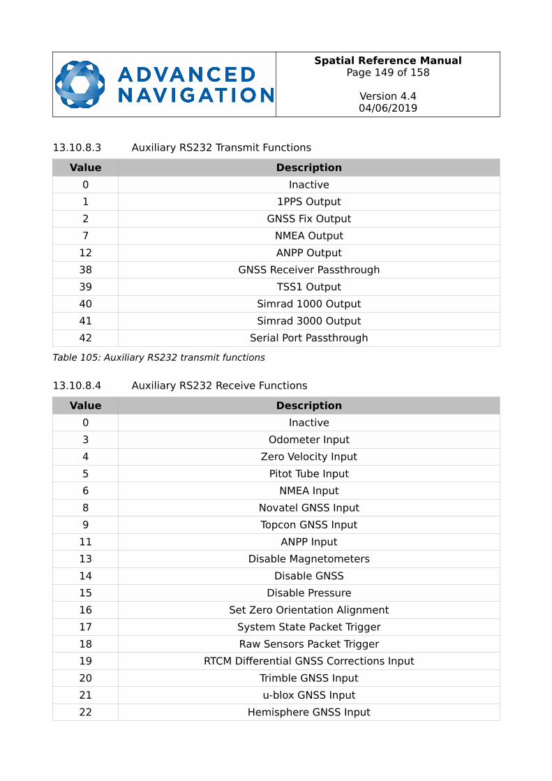
Spatial Reference ManualPage 149 of 158
Version 4.404/06/2019
13.10.8.3 Auxiliary RS232 Transmit Functions
Value Description
0 Inactive
1 1PPS Output
2 GNSS Fix Output
7 NMEA Output
12 ANPP Output
38 GNSS Receiver Passthrough
39 TSS1 Output
40 Simrad 1000 Output
41 Simrad 3000 Output
42 Serial Port Passthrough
Table 105: Auxiliary RS232 transmit functions
13.10.8.4 Auxiliary RS232 Receive Functions
Value Description
0 Inactive
3 Odometer Input
4 Zero Velocity Input
5 Pitot Tube Input
6 NMEA Input
8 Novatel GNSS Input
9 Topcon GNSS Input
11 ANPP Input
13 Disable Magnetometers
14 Disable GNSS
15 Disable Pressure
16 Set Zero Orientation Alignment
17 System State Packet Trigger
18 Raw Sensors Packet Trigger
19 RTCM Differential GNSS Corrections Input
20 Trimble GNSS Input
21 u-blox GNSS Input
22 Hemisphere GNSS Input
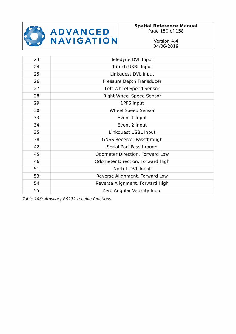
Spatial Reference ManualPage 150 of 158
Version 4.404/06/2019
23 Teledyne DVL Input
24 Tritech USBL Input
25 Linkquest DVL Input
26 Pressure Depth Transducer
27 Left Wheel Speed Sensor
28 Right Wheel Speed Sensor
29 1PPS Input
30 Wheel Speed Sensor
33 Event 1 Input
34 Event 2 Input
35 Linkquest USBL Input
38 GNSS Receiver Passthrough
42 Serial Port Passthrough
45 Odometer Direction, Forward Low
46 Odometer Direction, Forward High
51 Nortek DVL Input
53 Reverse Alignment, Forward Low
54 Reverse Alignment, Forward High
55 Zero Angular Velocity Input
Table 106: Auxiliary RS232 receive functions
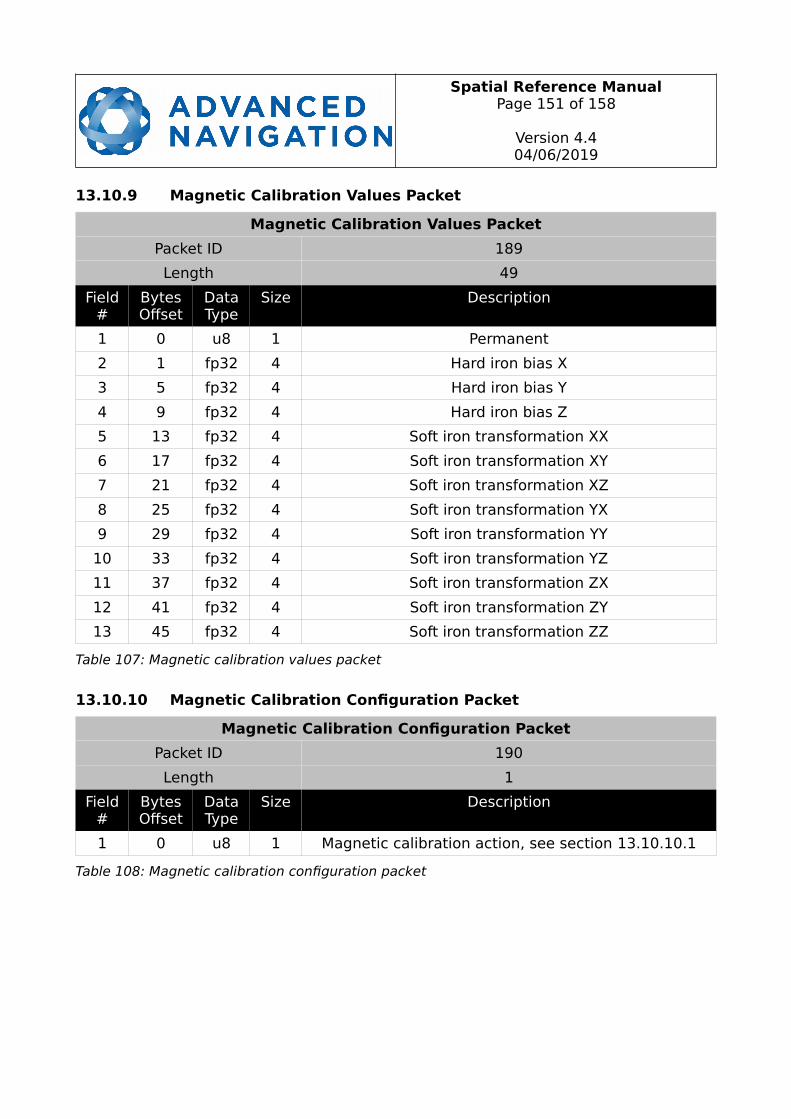
Spatial Reference ManualPage 151 of 158
Version 4.404/06/2019
13.10.9 Magnetic Calibration Values Packet
Magnetic Calibration Values Packet
Packet ID 189
Length 49
Field#
BytesOffset
DataType
Size Description
1 0 u8 1 Permanent
2 1 fp32 4 Hard iron bias X
3 5 fp32 4 Hard iron bias Y
4 9 fp32 4 Hard iron bias Z
5 13 fp32 4 Soft iron transformation XX
6 17 fp32 4 Soft iron transformation XY
7 21 fp32 4 Soft iron transformation XZ
8 25 fp32 4 Soft iron transformation YX
9 29 fp32 4 Soft iron transformation YY
10 33 fp32 4 Soft iron transformation YZ
11 37 fp32 4 Soft iron transformation ZX
12 41 fp32 4 Soft iron transformation ZY
13 45 fp32 4 Soft iron transformation ZZ
Table 107: Magnetic calibration values packet
13.10.10 Magnetic Calibration Configuration Packet
Magnetic Calibration Configuration Packet
Packet ID 190
Length 1
Field#
BytesOffset
DataType
Size Description
1 0 u8 1 Magnetic calibration action, see section 13.10.10.1
Table 108: Magnetic calibration configuration packet
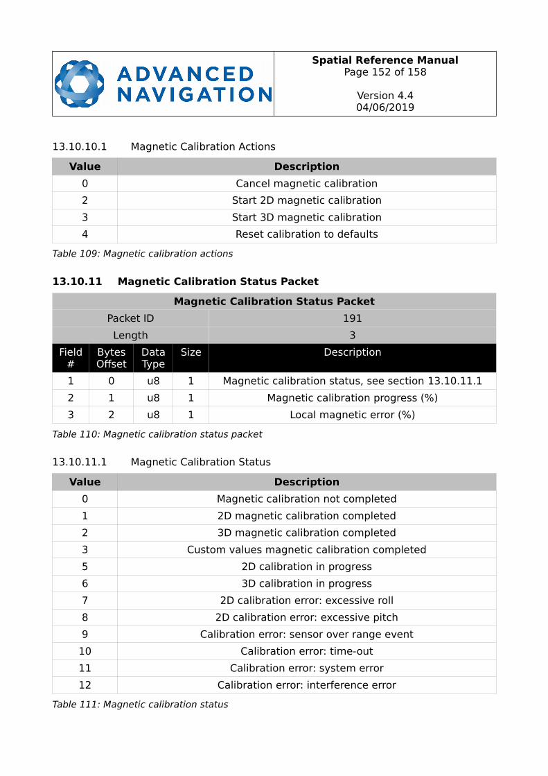
Spatial Reference ManualPage 152 of 158
Version 4.404/06/2019
13.10.10.1 Magnetic Calibration Actions
Value Description
0 Cancel magnetic calibration
2 Start 2D magnetic calibration
3 Start 3D magnetic calibration
4 Reset calibration to defaults
Table 109: Magnetic calibration actions
13.10.11 Magnetic Calibration Status Packet
Magnetic Calibration Status Packet
Packet ID 191
Length 3
Field#
BytesOffset
DataType
Size Description
1 0 u8 1 Magnetic calibration status, see section 13.10.11.1
2 1 u8 1 Magnetic calibration progress (%)
3 2 u8 1 Local magnetic error (%)
Table 110: Magnetic calibration status packet
13.10.11.1 Magnetic Calibration Status
Value Description
0 Magnetic calibration not completed
1 2D magnetic calibration completed
2 3D magnetic calibration completed
3 Custom values magnetic calibration completed
5 2D calibration in progress
6 3D calibration in progress
7 2D calibration error: excessive roll
8 2D calibration error: excessive pitch
9 Calibration error: sensor over range event
10 Calibration error: time-out
11 Calibration error: system error
12 Calibration error: interference error
Table 111: Magnetic calibration status
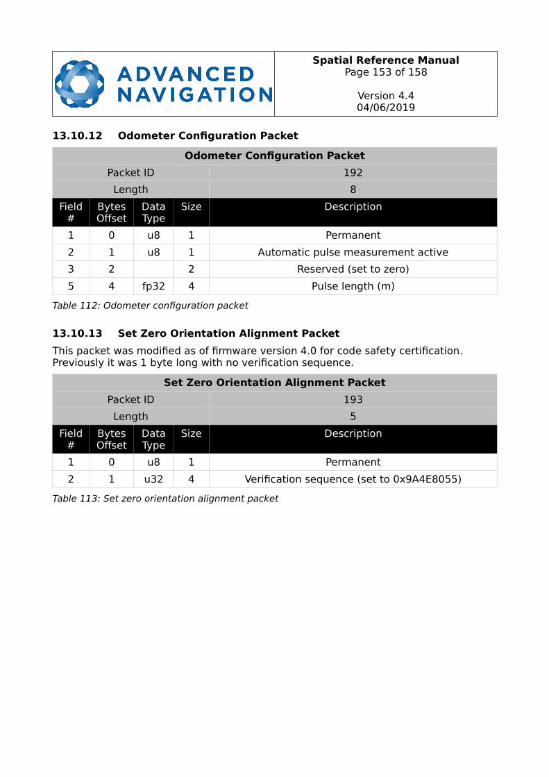
Spatial Reference ManualPage 153 of 158
Version 4.404/06/2019
13.10.12 Odometer Configuration Packet
Odometer Configuration Packet
Packet ID 192
Length 8
Field#
BytesOffset
DataType
Size Description
1 0 u8 1 Permanent
2 1 u8 1 Automatic pulse measurement active
3 2 2 Reserved (set to zero)
5 4 fp32 4 Pulse length (m)
Table 112: Odometer configuration packet
13.10.13 Set Zero Orientation Alignment Packet
This packet was modified as of firmware version 4.0 for code safety certification. Previously it was 1 byte long with no verification sequence.
Set Zero Orientation Alignment Packet
Packet ID 193
Length 5
Field#
BytesOffset
DataType
Size Description
1 0 u8 1 Permanent
2 1 u32 4 Verification sequence (set to 0x9A4E8055)
Table 113: Set zero orientation alignment packet
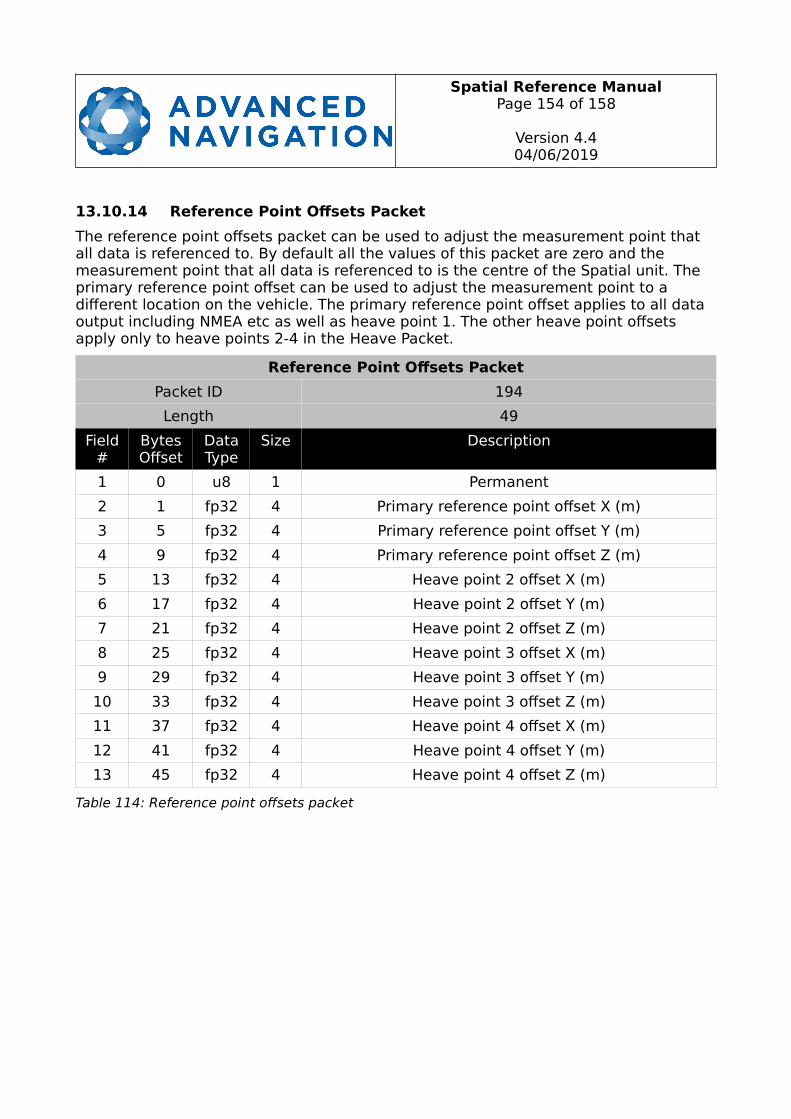
Spatial Reference ManualPage 154 of 158
Version 4.404/06/2019
13.10.14 Reference Point Offsets Packet
The reference point offsets packet can be used to adjust the measurement point that all data is referenced to. By default all the values of this packet are zero and the measurement point that all data is referenced to is the centre of the Spatial unit. The primary reference point offset can be used to adjust the measurement point to a different location on the vehicle. The primary reference point offset applies to all data output including NMEA etc as well as heave point 1. The other heave point offsets apply only to heave points 2-4 in the Heave Packet.
Reference Point Offsets Packet
Packet ID 194
Length 49
Field#
BytesOffset
DataType
Size Description
1 0 u8 1 Permanent
2 1 fp32 4 Primary reference point offset X (m)
3 5 fp32 4 Primary reference point offset Y (m)
4 9 fp32 4 Primary reference point offset Z (m)
5 13 fp32 4 Heave point 2 offset X (m)
6 17 fp32 4 Heave point 2 offset Y (m)
7 21 fp32 4 Heave point 2 offset Z (m)
8 25 fp32 4 Heave point 3 offset X (m)
9 29 fp32 4 Heave point 3 offset Y (m)
10 33 fp32 4 Heave point 3 offset Z (m)
11 37 fp32 4 Heave point 4 offset X (m)
12 41 fp32 4 Heave point 4 offset Y (m)
13 45 fp32 4 Heave point 4 offset Z (m)
Table 114: Reference point offsets packet
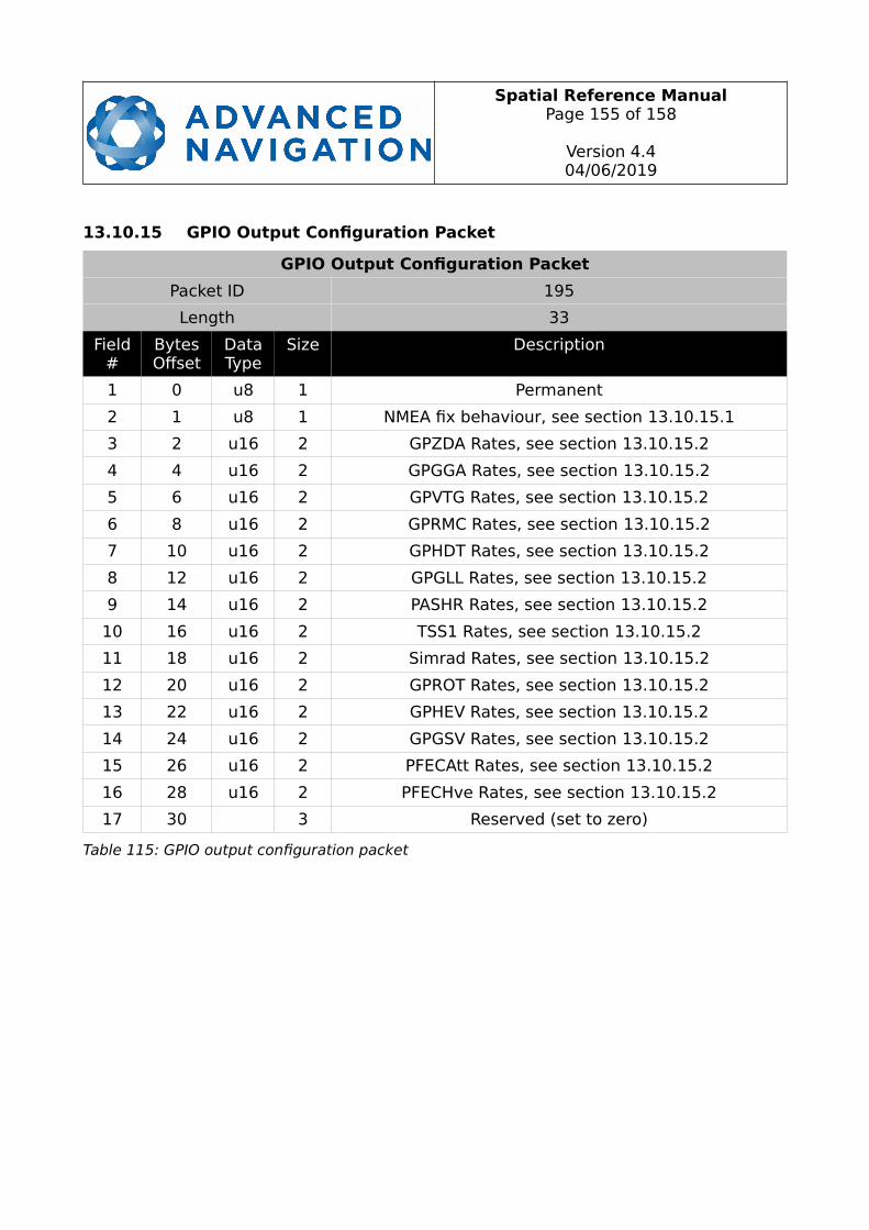
Spatial Reference ManualPage 155 of 158
Version 4.404/06/2019
13.10.15 GPIO Output Configuration Packet
GPIO Output Configuration Packet
Packet ID 195
Length 33
Field#
BytesOffset
DataType
Size Description
1 0 u8 1 Permanent
2 1 u8 1 NMEA fix behaviour, see section 13.10.15.1
3 2 u16 2 GPZDA Rates, see section 13.10.15.2
4 4 u16 2 GPGGA Rates, see section 13.10.15.2
5 6 u16 2 GPVTG Rates, see section 13.10.15.2
6 8 u16 2 GPRMC Rates, see section 13.10.15.2
7 10 u16 2 GPHDT Rates, see section 13.10.15.2
8 12 u16 2 GPGLL Rates, see section 13.10.15.2
9 14 u16 2 PASHR Rates, see section 13.10.15.2
10 16 u16 2 TSS1 Rates, see section 13.10.15.2
11 18 u16 2 Simrad Rates, see section 13.10.15.2
12 20 u16 2 GPROT Rates, see section 13.10.15.2
13 22 u16 2 GPHEV Rates, see section 13.10.15.2
14 24 u16 2 GPGSV Rates, see section 13.10.15.2
15 26 u16 2 PFECAtt Rates, see section 13.10.15.2
16 28 u16 2 PFECHve Rates, see section 13.10.15.2
17 30 3 Reserved (set to zero)
Table 115: GPIO output configuration packet
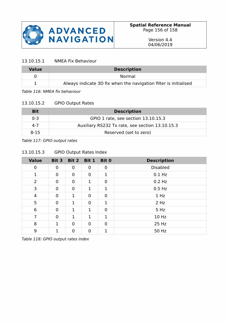
Spatial Reference ManualPage 156 of 158
Version 4.404/06/2019
13.10.15.1 NMEA Fix Behaviour
Value Description
0 Normal
1 Always indicate 3D fix when the navigation filter is initialised
Table 116: NMEA fix behaviour
13.10.15.2 GPIO Output Rates
Bit Description
0-3 GPIO 1 rate, see section 13.10.15.3
4-7 Auxiliary RS232 Tx rate, see section 13.10.15.3
8-15 Reserved (set to zero)
Table 117: GPIO output rates
13.10.15.3 GPIO Output Rates Index
Value Bit 3 Bit 2 Bit 1 Bit 0 Description
0 0 0 0 0 Disabled
1 0 0 0 1 0.1 Hz
2 0 0 1 0 0.2 Hz
3 0 0 1 1 0.5 Hz
4 0 1 0 0 1 Hz
5 0 1 0 1 2 Hz
6 0 1 1 0 5 Hz
7 0 1 1 1 10 Hz
8 1 0 0 0 25 Hz
9 1 0 0 1 50 Hz
Table 118: GPIO output rates index
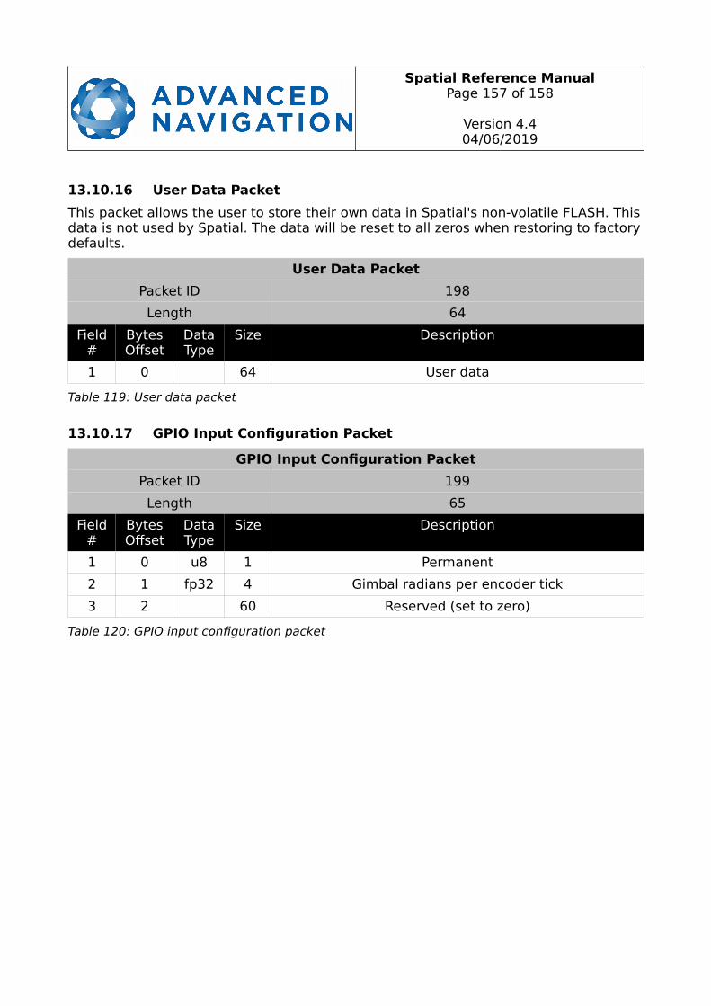
Spatial Reference ManualPage 157 of 158
Version 4.404/06/2019
13.10.16 User Data Packet
This packet allows the user to store their own data in Spatial's non-volatile FLASH. Thisdata is not used by Spatial. The data will be reset to all zeros when restoring to factorydefaults.
User Data Packet
Packet ID 198
Length 64
Field#
BytesOffset
DataType
Size Description
1 0 64 User data
Table 119: User data packet
13.10.17 GPIO Input Configuration Packet
GPIO Input Configuration Packet
Packet ID 199
Length 65
Field#
BytesOffset
DataType
Size Description
1 0 u8 1 Permanent
2 1 fp32 4 Gimbal radians per encoder tick
3 2 60 Reserved (set to zero)
Table 120: GPIO input configuration packet

Spatial Reference ManualPage 158 of 158
Version 4.404/06/2019
Information in this document is provided solely in connection with Advanced Navigation products. Advanced Navigationreserves the right to make changes, corrections, modifications or improvements, to this document, and the products and services described herein at any time, without notice.
All Advanced Navigation products are sold pursuant to Advanced Navigation’s terms and conditions of sale. Purchasers are solely responsible for the choice, selection and use of the Advanced Navigation products and services described herein, and Advanced Navigation assumes no liability whatsoever relating to the choice, selection or use of the Advanced Navigation products and services described herein.
No license, express or implied, by estoppel or otherwise, to any intellectual property rights is granted under this document. If any part of this document refers to any third party products or services it shall not be deemed a license grant by Advanced Navigation for the use of such third party products or services, or any intellectual property contained therein or considered as a warranty covering the use in any manner whatsoever of such third party products or services or any intellectual property contained therein.
UNLESS OTHERWISE SET FORTH IN ADVANCED NAVIGATION’S TERMS AND CONDITIONS OF SALE ADVANCED NAVIGATION DISCLAIMS ANY EXPRESS OR IMPLIED WARRANTY WITH RESPECT TO THE USE AND/OR SALE OF ADVANCEDNAVIGATION PRODUCTS INCLUDING WITHOUT LIMITATION IMPLIED WARRANTIES OF MERCHANTABILITY, FITNESS FOR A PARTICULAR PURPOSE (AND THEIR EQUIVALENTS UNDER THE LAWS OF ANY JURISDICTION), OR INFRINGEMENT OF ANY PATENT, COPYRIGHT OR OTHER INTELLECTUAL PROPERTY RIGHT.
UNLESS EXPRESSLY APPROVED IN WRITING BY TWO AUTHORIZED ADVANCED NAVIGATION REPRESENTATIVES, ADVANCED NAVIGATION PRODUCTS ARE NOT RECOMMENDED, AUTHORIZED OR WARRANTED FOR USE IN MILITARY, AIRCRAFT, SPACE, LIFE SAVING, OR LIFE SUSTAINING APPLICATIONS, NOR IN PRODUCTS OR SYSTEMS WHERE FAILURE OR MALFUNCTION MAY RESULT IN PERSONAL INJURY, DEATH, OR SEVERE PROPERTY OR ENVIRONMENTAL DAMAGE.
ADVANCED NAVIGATION PRODUCTS WHICH ARE NOT SPECIFIED AS "AUTOMOTIVE GRADE" MAY ONLY BE USED IN AUTOMOTIVE APPLICATIONS AT USER’S OWN RISK.
Resale of Advanced Navigation products with provisions different from the statements and/or technical features set forth in this document shall immediately void any warranty granted by Advanced Navigation for the Advanced Navigation product or service described herein and shall not create or extend in any manner whatsoever, any liability of Advanced Navigation.
Information in this document supersedes and replaces all information previously supplied.
© 2019 Advanced Navigation - All rights reserved