speaker & panellist panellist
TRANSCRIPT
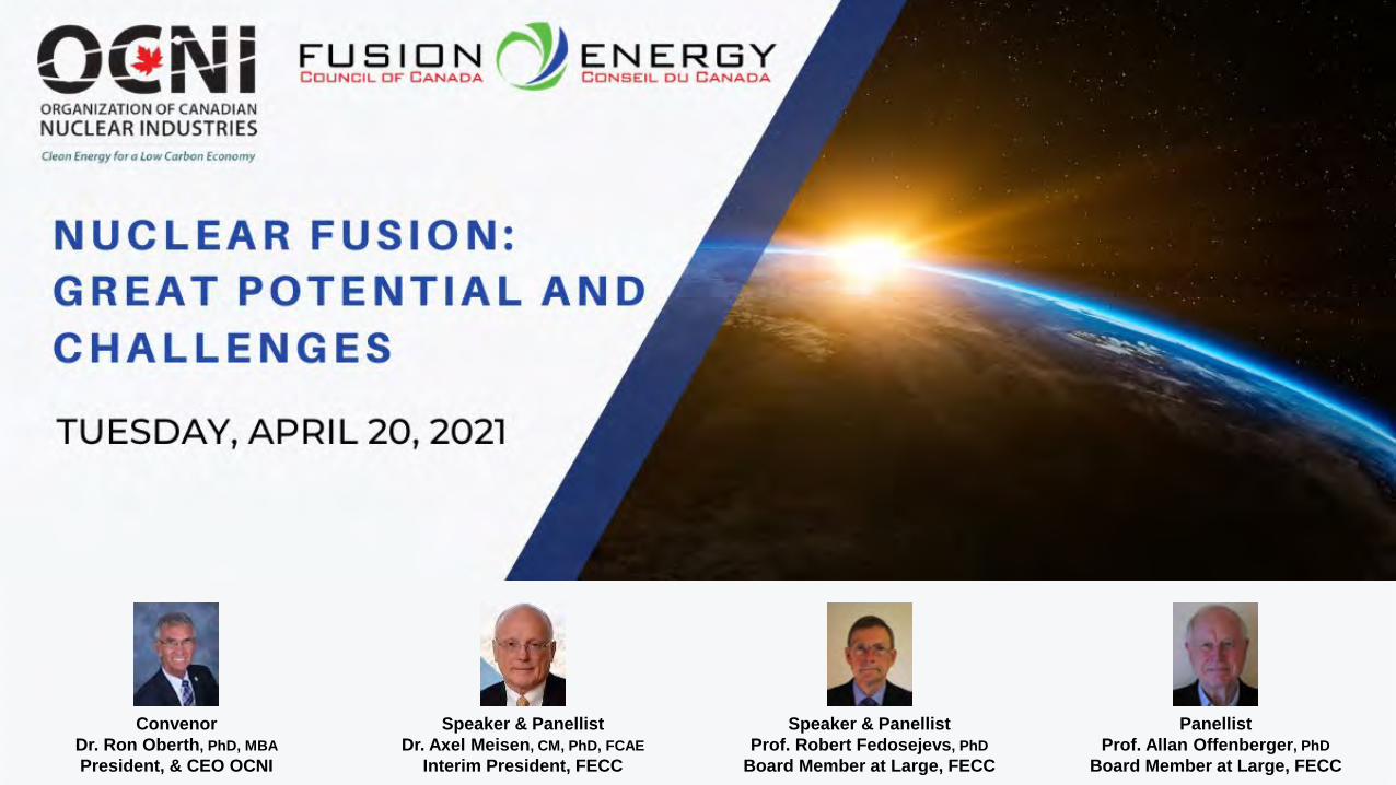
Speaker & PanellistDr. Axel Meisen, CM, PhD, FCAE
Interim President, FECC
Speaker & PanellistProf. Robert Fedosejevs, PhD
Board Member at Large, FECC
PanellistProf. Allan Offenberger, PhD
Board Member at Large, FECC
ConvenorDr. Ron Oberth, PhD, MBAPresident, & CEO OCNI

FECC – OCNI MOU – MARCH 11, 2021
FECC and OCNI will collaborate in:
• Communicating the benefits of fusion energy to public and technical audiences in Canada
• Encouraging technical exchanges amoung Canadian fusion specialists and the Canadian nuclear supply chain
• Hosting joint technical and informational seminars and webinars on fusion energy


Analogy: Human Flight
Slide 4
1485 1783Antiquity
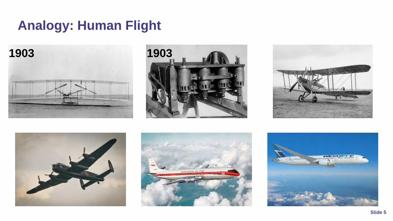
Analogy: Human Flight
Slide 5
1903 1903

Fusion Energy
Slide 6

Fundamentals
Fusion:Light nuclei combine to form larger nuclei and neutrons
Slide 7Change in mass is converted into energy
Fission:Heavy nuclei split to form smaller nuclei and neutrons
Energy Energy
2H
3H
4He
n
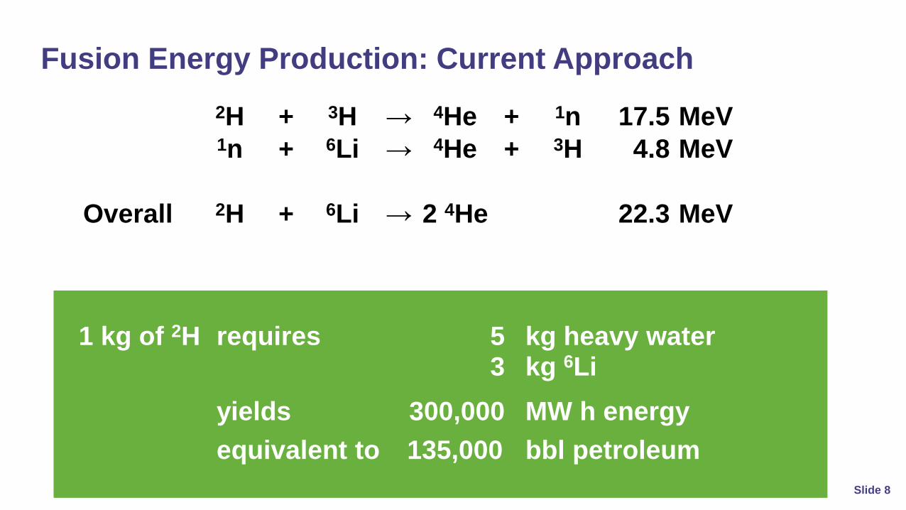
Fusion Energy Production: Current Approach
Slide 8
2H + 3H → 4He + 1n 17.5 MeV1n + 6Li → 4He + 3H 4.8 MeV
Overall 2H + 6Li → 2 4He 22.3 MeV
1 kg of 2H requires 5 kg heavy water3 kg 6Li
yields 300,000 MW h energyequivalent to 135,000 bbl petroleum

Fusion Energy Production: Current Approach
Slide 9
1 million bblpetroleum ≡ 2,200,000 MW h energy
7.4 kg 2H22 kg 6Li
37 kg heavy waterfrom≡
Overall 2H + 6Li → 2 4He 22.3 MeV

Some Fusion Reactions – no radioactive products
(1a) 2H + 3H → 4He + 1n + energy (17.6 MeV) (D-T fusion)(1b) 1n + 6Li → 4He + 3H + energy ( 4.8 MeV) (3H fuel breeding cycle)(1c) 1n (fast) + 7Li → 4He + 3H + 1n (-2.4 MeV) (3H fuel breeding cycle)
(2a) 2H + 2H → 3H + p+ + energy (4.03 MeV) (50%) (D-D fusion, no T breeding)(2b) 2H + 2H → 3He + 1n + energy (3.27 MeV) (50%)(2c) 2H + 3He → 4He + p+ + energy (18.3 MeV)
(3) p+ + 11B → 3 4He + energy (8.7 MeV) (p-B11 fusion, no neutrons)
Nomenclature: : 1H+=p+ (proton); 2H=D (deuteron or deuterium); 3H=T (triton or tritium); ); 4H=alpha particle
Fusion reaction (change of mass), releases energy E=Δm c2, > million x chemical reaction energy
Energy From Fusion Reactions
Slide 10

Fusion reactions require high energy ● to overcome Coulomb repulsion of (positive) nuclei ● temperature T ~ 100 MK, KE/particle ~ 10 keV● all matter is ionized at high T to form a plasma (4th state of matter)
Plasma (ions & electrons) must be confined ● energetic particles escape very rapidly ( vDeuterium ~ 1 x 10⁶ m/s at 10 keV)● need confinement mechanism to ensure enough reactions occur to give net energy yield
Plasma burn● to maintain burning plasma use alpha particle heating● alpha particles released by fusion reactions are very collisional● requires minimum reaction volume
Fusion Reactions
Slide 11

Pfus = nD nT <συ> Efus
Efus = 17.6 MeV (D-T)
Require sufficient particle energy for strong nuclear force to “overcome” Coulomb repulsive force – quantum tunneling at close range
For D-T fusion Power Per Unit Volume
Fusion Reactivity
Slide 12

Fusion - Lawson Criterion
Slide 13
n τ E > 2x10²⁰ s/m3 (D-T)
n = plasma density ( n = ni = ne )τE = Energy Confinement Time
Leads to Lawson Breakeven Criterion
RequirePfus > Ploss

● Need high temperature for ignition: Tign ≥ 100 million deg K
● Need confinement for net energy out: nτ > 2x10²⁰ m-3 sec
● Burning occurs when heating is self-sustained (by helium from fusion)
● Two confinement approaches: (i) magnetic (MFE); (ii) inertial (IFE)
MFE – ignition requiresohmic & auxiliary heating
Fuel Burn
IFE – ignition requires driver beamsto heat & compress target
Meeting Conditions for Fusion Energy
Slide 14
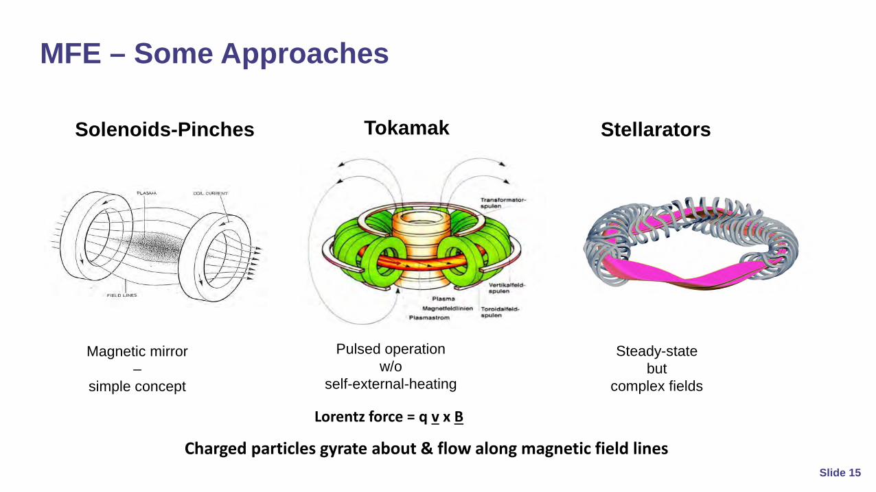
Tokamak StellaratorsSolenoids-Pinches
Magnetic mirror –
simple concept
Steady-state but
complex fields
Pulsed operation w/o
self-external-heating
Charged particles gyrate about & flow along magnetic field lines
Lorentz force = q v x B
MFE – Some Approaches
Slide 15

Parallel motion, Gyration, E cross B drift, Polarization drift , Curvature & grad B drift
For Toroidal Plasma:Combined Drifts Lead to loss of plasma
Charged Particles Drifts in Magnetic FieldsCharged particles also drift slowly across magnetic field lines leading to loss of plasma
Complex Drift due to Magnetic and Electric Forces
Slide 16
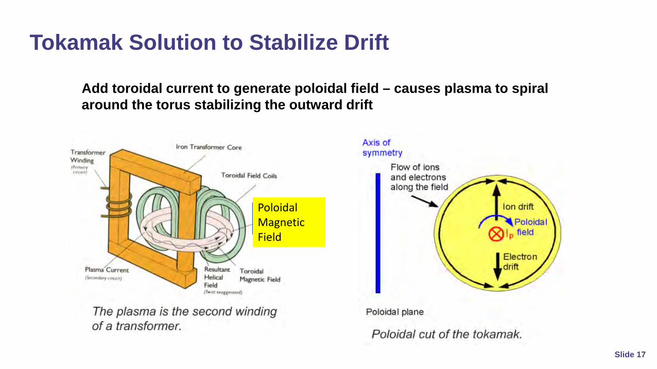
Add toroidal current to generate poloidal field – causes plasma to spiral around the torus stabilizing the outward drift
Tokamak Solution to Stabilize Drift
PoloidalMagnetic Field
Slide 17

MCF requires auxiliary heating to achieve ignition – neutral beam injection; electromagnetic heating
Objective: to achieve low density steady-state burning (Q=10); test technologies; tritium breeding
Q = Pout/Pin > 1
ITER – International Project in France to scale-up Tokamak (operational by 2027)
Plasma drifts & Instabilities limit confinement
β = plasma pressure / magnetic pressure
β = <P>/(B2/2 μo) ≈< 0.1
Tokamak – Most Advanced Magnetic
Slide 18
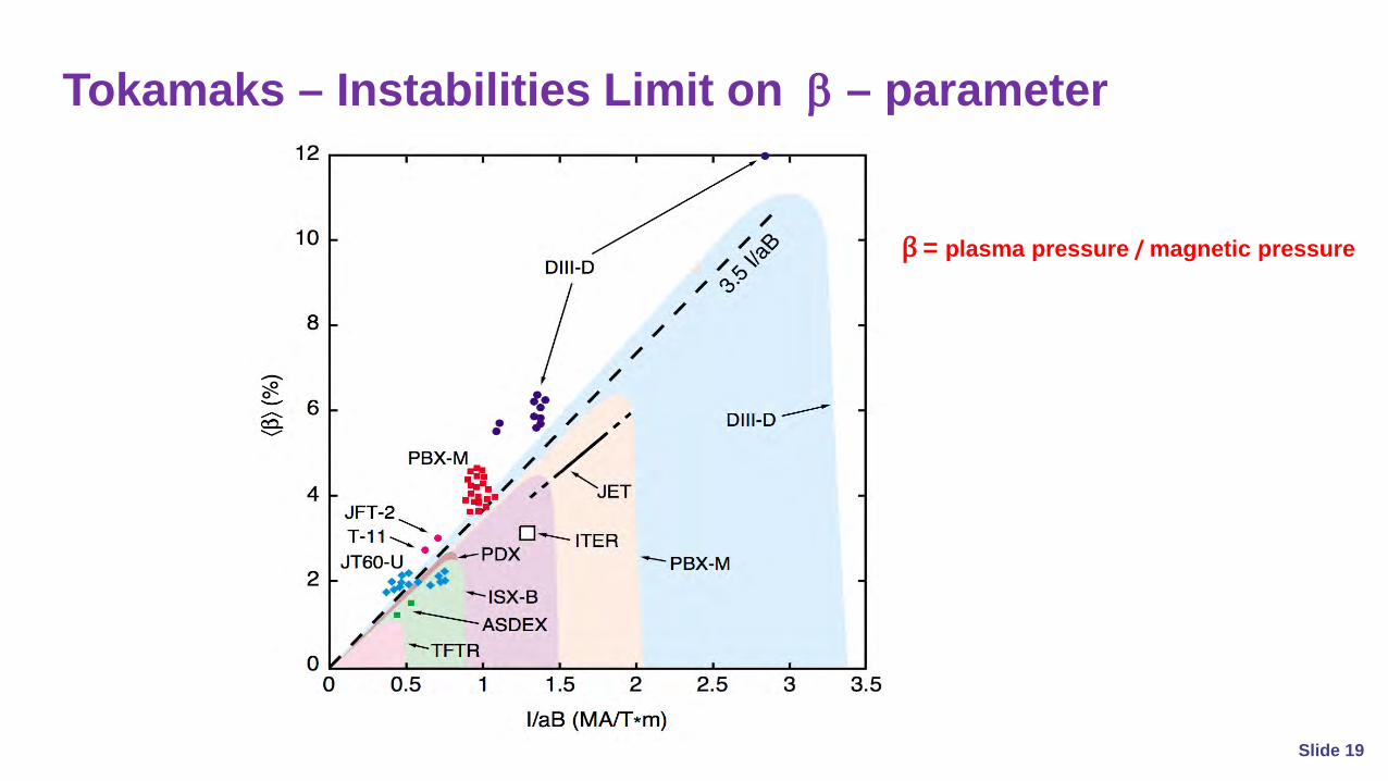
Tokamaks – Instabilities Limit on β – parameter
β = plasma pressure / magnetic pressure
Slide 19

Laser Driven - Fusion capsule imploded by laser beams into a central hot spot leading to Central Ignition of Fusion Reactions
Uses shaped laser pulse
Laser Intensity = 500 TW/cm2
Requires fuel compression for net energy gain
IFE – Some Approaches
Slide 20

GenerateElectricity
Two compression pathways – direct & indirect drive
Indirect – laser irradiated hohlraum– laser energy converted to x-rays
which then compress & heat target
HeatHelium
Laser irradiation Ablation/compression Ignition Burn
How Inertial Fusion Works
Direct – laser compresses and heats fuel pellet directly
Slide 21

● Magnetic fusion (continuous, power delivery)- ~ 50 MW heater beams- pressure <10atm- ~1 MW/m3; large volume, low density- ~1 MW/m2 wall irradiance (radiation, charged particles, neutrons)
● Inertial fusion (pulsed, repetitive energy delivery, ~10 Hz)- High Energy Laser Diver Pulse ~ 1 MJ- pressure >1011 atm- small volume (~100 µm), high density - short burn time ~10-10 sec- operates like a “diesel engine”
Relative Power/Energy Density – D-T Fusion
Slide 22

Tokamaks – Progress
Slide 23
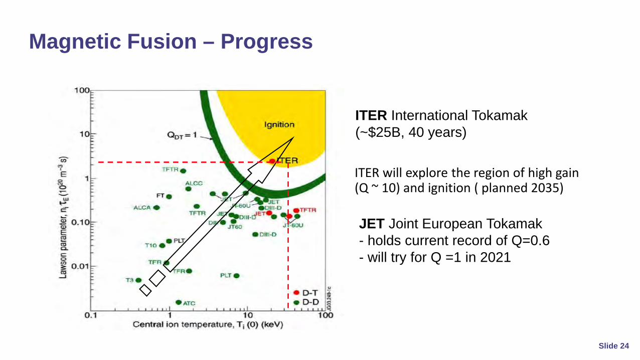
ITER will explore the region of high gain (Q ~ 10) and ignition ( planned 2035)
ITER International Tokamak (~$25B, 40 years)
Magnetic Fusion – Progress
JET Joint European Tokamak - holds current record of Q=0.6- will try for Q =1 in 2021
Slide 24
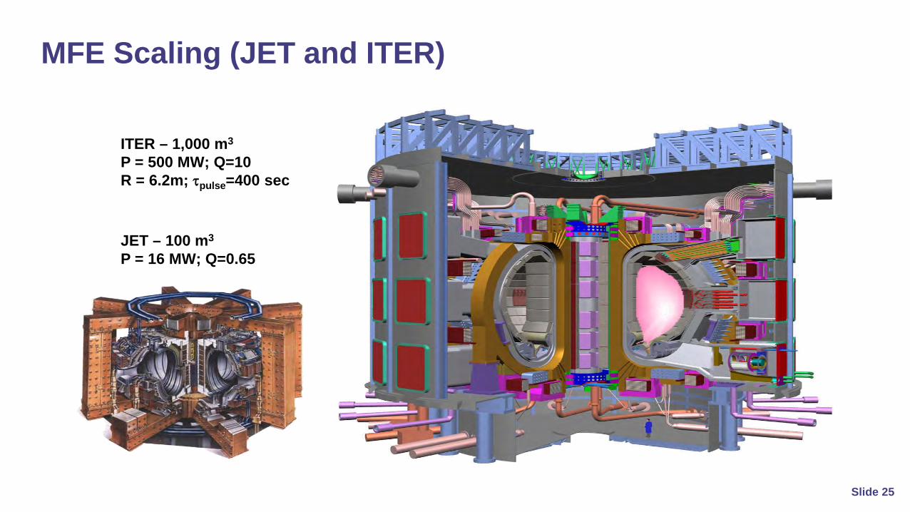
JET – 100 m3
P = 16 MW; Q=0.65
ITER – 1,000 m3
P = 500 MW; Q=10R = 6.2m; τpulse=400 sec
MFE Scaling (JET and ITER)
Slide 25

ITER Current Construction Progress Cadarache France (~ 50% complete)https://www.iter.org/
ITER – 1,000 m3
P = 500 MW; Q=10R = 6.2m; τpulse=400 sec
Slide 26

Indirect drive at LLNL
Inertial Fusion - Progress
National Ignition Facility (NIF)at Lawrence Livermore National Laboratory
• 160kJ neutron energy per pulse• within a factor of ~2 of ignition and burn
Slide 27
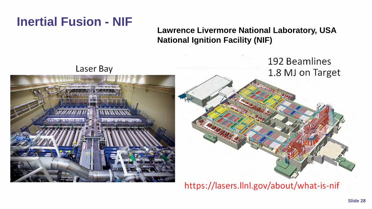
Inertial Fusion - NIFLawrence Livermore National Laboratory, USANational Ignition Facility (NIF)
Slide 28
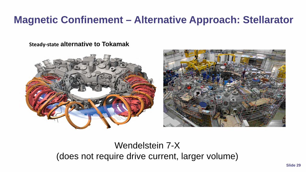
Wendelstein 7-X(does not require drive current, larger volume)
Steady-state alternative to Tokamak
Magnetic Confinement – Alternative Approach: Stellarator
Slide 29
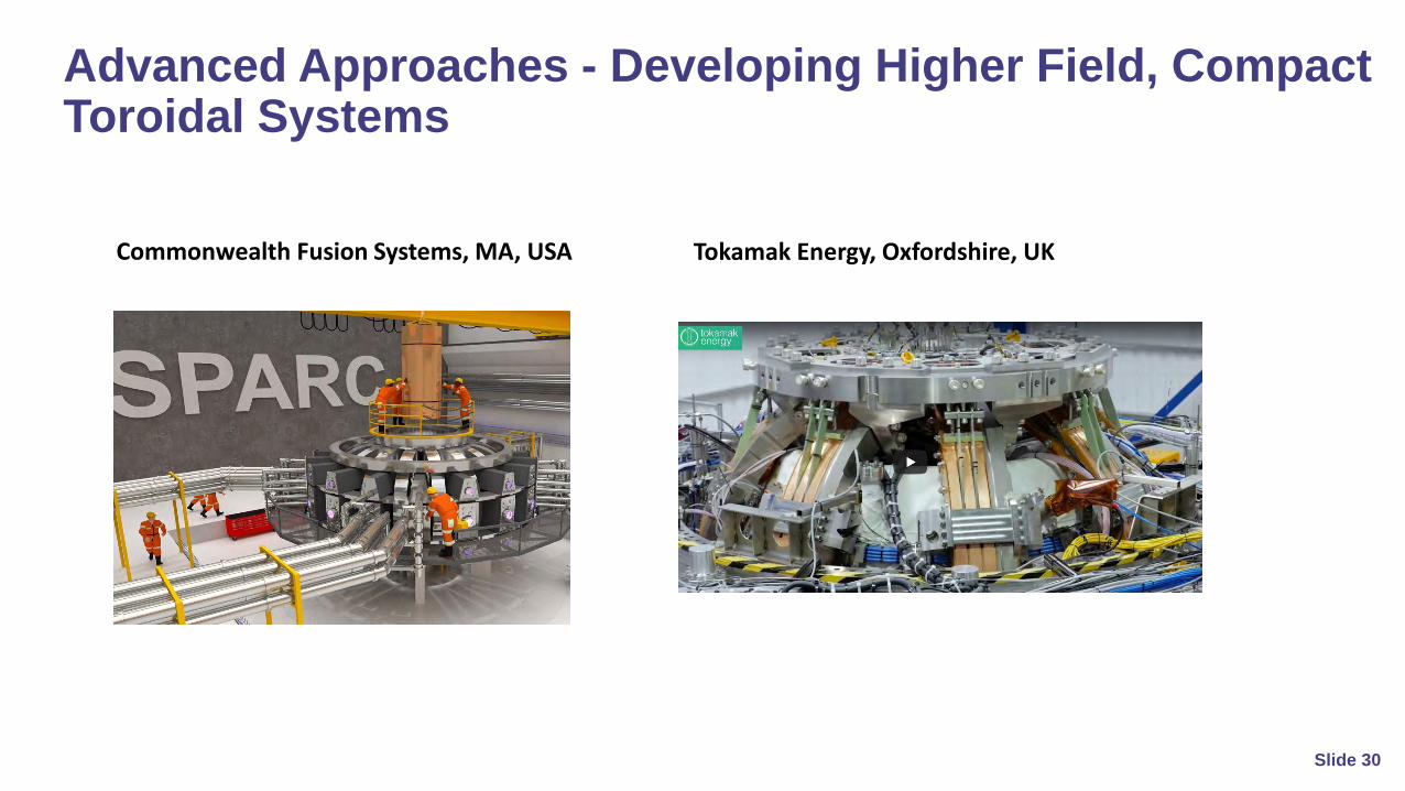
Commonwealth Fusion Systems, MA, USA
Advanced Approaches - Developing Higher Field, Compact Toroidal Systems
Tokamak Energy, Oxfordshire, UK
Slide 30

Fast Ignition Shock Ignition
Uses PW, ps Pulse as an igniter SparkLaser Intensity=1020 W/cm2
Uses high power peak at the end of a shaped compression pulse to drive a strong shock wave to ignite the compressed fuel
Advanced Approaches to IFE – Fast Ignition and Shock Ignition Concepts
Slide 31

Laser driver is a major capital cost item
Improved Performance for Advanced Laser ConceptsHigher Gain at Reduced Laser Energy
Slide 32

Commonwealth Fusion Systems, MA, USA
General Fusion, Burnaby, CanadaTri-Alpha Energy (TAE), CA, USA
Companies with Fusion Goals for 2030’sTokamak Energy, Oxfordshire, UK
Slide 33

First Light fusion, Oxford, UK
HB11, NSW, Australia
Companies with Fusion Goals for 2030’s 2nd slide
● A number of companies are pursuing alternative concept approaches
● Private Investments of tens of millions to hundreds of millions of dollars
Helion Energy, WA, USA
Slide 34

● Control of plasma instabilities (require better diagnostics and 3D simulations)
● Achievement of ignition and gain of Q ≥ 10 (large scale experiments, ~ $1-5B each)
● Real time tritium breeding and extraction (develop much faster processing techniques)
● Neutron damage and activation- develop low activation steels and materials- develop neutron damage resistant materials ( ~100 dpa lifetimes)
● Robotics for remote servicing of all components- radiation tolerant robotics for servicing and maintenance
Science and Engineering Challenges
Each technical area requires ~ 10 years of R&D ⇒Could be done in parallel
Slide 35

Example Reactor Activation (only waste product produced)
Slide 36
● Mitigation of Major Disruptions (rapid injection of cold gas pellets)
● High field, high temperature superconductors
● Fueling - continuous injection of D/T fuel pellets
● Radiation damage resistance of cryogenic magnets and systems (advanced materials)
● Extreme power flux on divertor panels (high temperature refractory alloys, high efficiency cooling)
MFE - Specific Science and Engineering Challenges
Challenges being addressed in various MFE research programs around the world
Slide 37

● Control of laser-plasma and plasma instabilities (target design and laser drive)
● Efficient broad-band laser drivers (> 10% electric to optical efficiency)- >20% efficient diode pumped lasers under development- requires special spectral characteristics to mitigate instabilities
● High damage resistance optical components
● Mass production of fuel pellets ( microfluidic and other manufacturing techniques)
IFE - Specific Science and Engineering Challenges
Challenges being addressed in numerous Laser facilities around the world
Slide 38

Fusion Business Challenges
Funding
Personnel
Markets
StrategyFECC
with partners
Slide 39
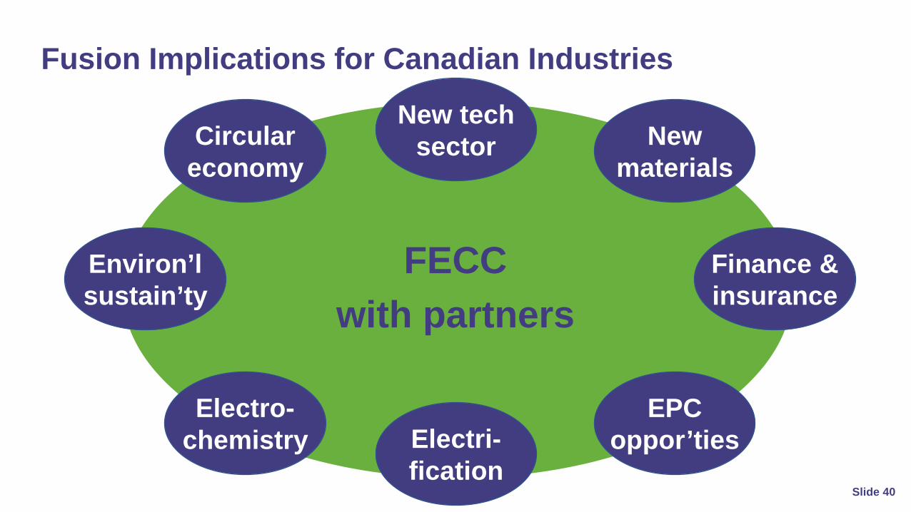
Fusion Implications for Canadian Industries
New tech sector
Electro-chemistry
EPC oppor’ties
Finance & insurance
Circular economy
Electri-fication
New materials
FECCwith partners
Environ’lsustain’ty
Slide 40

Fusion Implications for Canadians
New jobs
Job tran-sitions
Energy security
Environ’lquality
FECCwith partners
Slide 41

Conclusions
1. Fusion energy and uses will become new realities, with great potential and challenges
2. Canada must participate in creating the new fusion realities3. Partnerships and collaboration accelerate fusion realization4. Nuclear fusion and fission are symbiotic sectors5. FECC and OCNI are symbiotic partners with great futures
Slide 42
Acknowledgement and Ownership
Some images in this presentation were taken from publicly available websites, with their use being gratefully acknowledged and restricted to this presentation.
The Fusion Energy Council of Canada (FECC) is the sole owner of this presentation, which was prepared by Axel Meisen and Robert Fedosejevs. The presentation and its contents are for informational and educational purposes only. FECC is a non-profit organization.
Slide 43

Speaker & PanellistDr. Axel Meisen, CM, PhD, FCAE
Interim President, FECC
Speaker & PanellistProf. Robert Fedosejevs, PhD
Board Member at Large, FECC
PanellistProf. Allan Offenberger, PhD
Board Member at Large, FECC
ConvenorDr. Ron Oberth, PhD, MBAPresident, & CEO OCNI
Questions & Answers