speakers patrick bruce and chris bath sut 18/06/14 · speakers patrick bruce and chris bath sut...
TRANSCRIPT
Design considerations for subsea
metrology measurements
Speakers Patrick Bruce and Chris Bath SUT 18/06/14
Design Considerations for Subsea metrology measurements
• Mechanical Design considerations
• Measurement requirements
• Required measurement and what can be achieved
• Examples of metrology measurements
• Mechanical Jig Metrology
• Bracket Design and offset measurements
• Golden rules for Metrology
• Engineering Considerations for spools, Risers, pipe work (Patrick
Bruce)
Topics to be discussed
Design considerations for Subsea Metrology 2
Design Considerations for Subsea metrology measurements
• Material properties (Pipe size, wall thickness, composition of
the metal)
• Fabrication tolerances
• Expansion/ Contraction of the pipe work due to heat/cooling.
• Installation tolerance between each end (heading, pitch, roll and
position)
• Seabed friction (if applicable)
• Accuracy of subsea measurement
• Optimise costs for all of the above
Design Consideration
Design considerations for Subsea Metrology 3
Additional Engineering Considerations
Flow rate
Design life
pressure rating
Design Considerations for Subsea metrology measurements
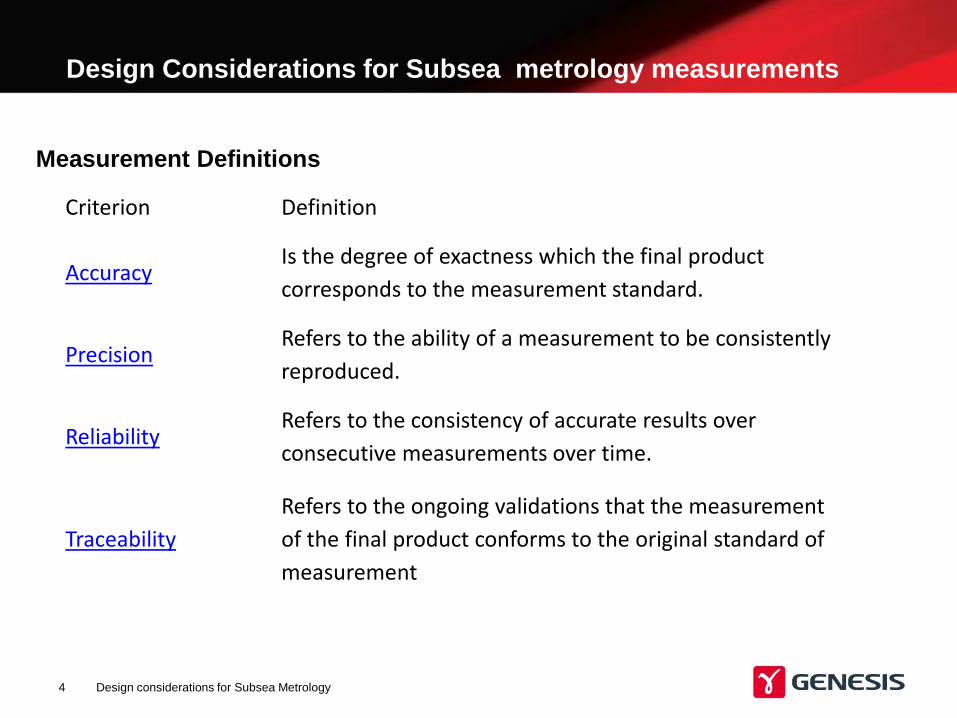
Measurement Definitions
Design considerations for Subsea Metrology 4
Criterion Definition
Accuracy Is the degree of exactness which the final product
corresponds to the measurement standard.
Precision Refers to the ability of a measurement to be consistently
reproduced.
Reliability Refers to the consistency of accurate results over
consecutive measurements over time.
Traceability
Refers to the ongoing validations that the measurement
of the final product conforms to the original standard of
measurement
• Engineers think +/- millimetres
• Surveyors think a range of centimetres
• Engineers do not understand accuracy's that can be achieved subsea
• Surveyors do no understand the design requirements.
• Engineers can normally widen the tolerances by making a few
modifications. But this usually adds costs.
• Surveyors can assist engineering with the choice of equipment, but
high accuracy comes at a price.
• We need to get together
Design considerations for Subsea Metrology 5
Engineers and Surveyors
Design Considerations for Subsea metrology measurements
Examples of Metology measurement
Design considerations for Subsea Metrology 6
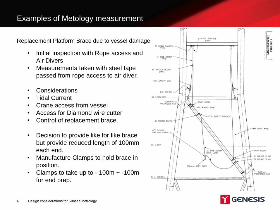
Replacement Platform Brace due to vessel damage
• Initial inspection with Rope access and
Air Divers
• Measurements taken with steel tape
passed from rope access to air diver.
• Considerations
• Tidal Current
• Crane access from vessel
• Access for Diamond wire cutter
• Control of replacement brace.
• Decision to provide like for like brace
but provide reduced length of 100mm
each end.
• Manufacture Clamps to hold brace in
position.
• Clamps to take up to - 100m + -100m
for end prep.
Examples of Metrology measurement
Design considerations for Subsea Metrology 7
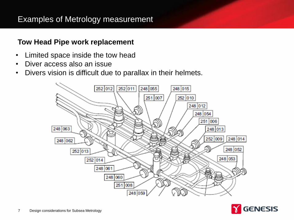
Tow Head Pipe work replacement
• Limited space inside the tow head
• Diver access also an issue
• Divers vision is difficult due to parallax in their helmets.
Examples of Metrology measurement
Design considerations for Subsea Metrology 8
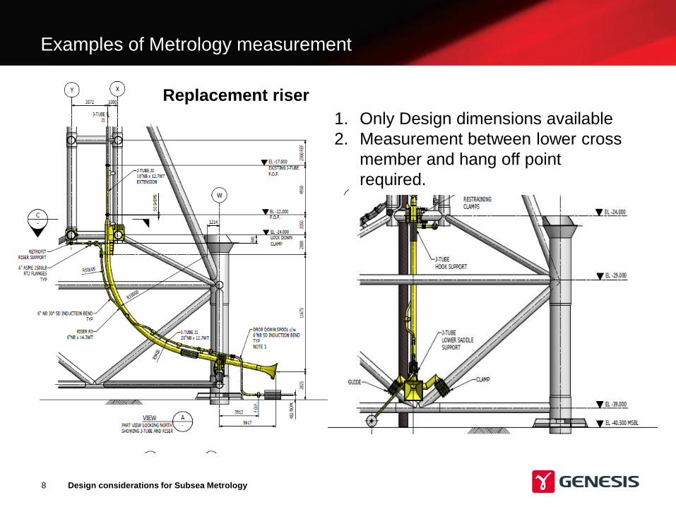
1. Only Design dimensions available
2. Measurement between lower cross
member and hang off point
required.
Replacement riser
Mechanical Jig Metrology
Design considerations for Subsea Metrology 9
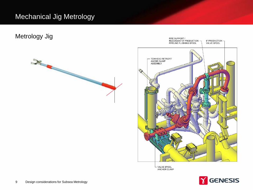
Metrology Jig
Design considerations for Subsea Metrology 10
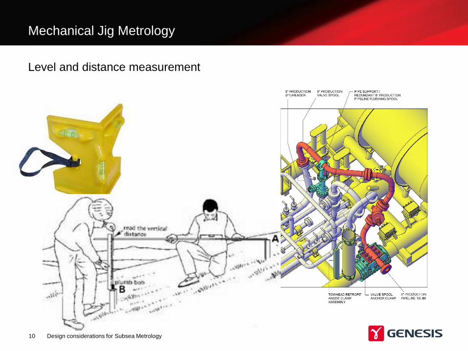
Level and distance measurement
Mechanical Jig Metrology
Design considerations for Subsea Metrology 11
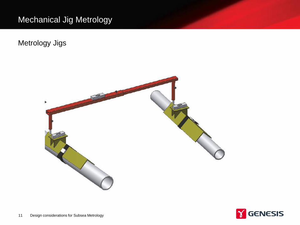
Metrology Jigs
Mechanical Jig Metrology
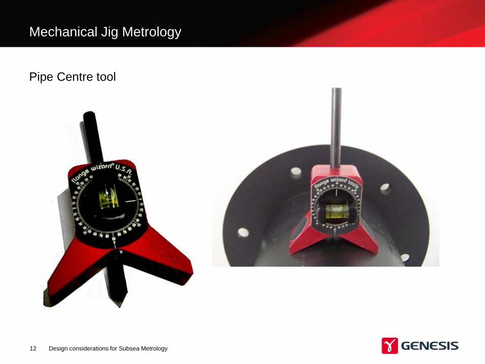
Pipe Centre tool
Design considerations for Subsea Metrology 12
Mechanical Jig Metrology
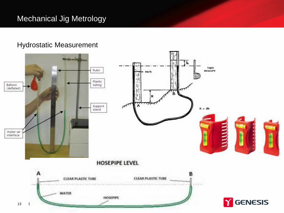
Hydrostatic Measurement
Design considerations for Subsea Metrology 13
Mechanical Jig Metrology
Design Considerations for Subsea metrology measurements
• Time spent on making good brackets so that offsets are known
in XY & Z is a sound investment.
• Use of Gyros to obtain heading pitch and roll measurements.
Importance of knowing where the measurements are taken from
Design considerations for Subsea Metrology 14
Bracket design and offset measurement
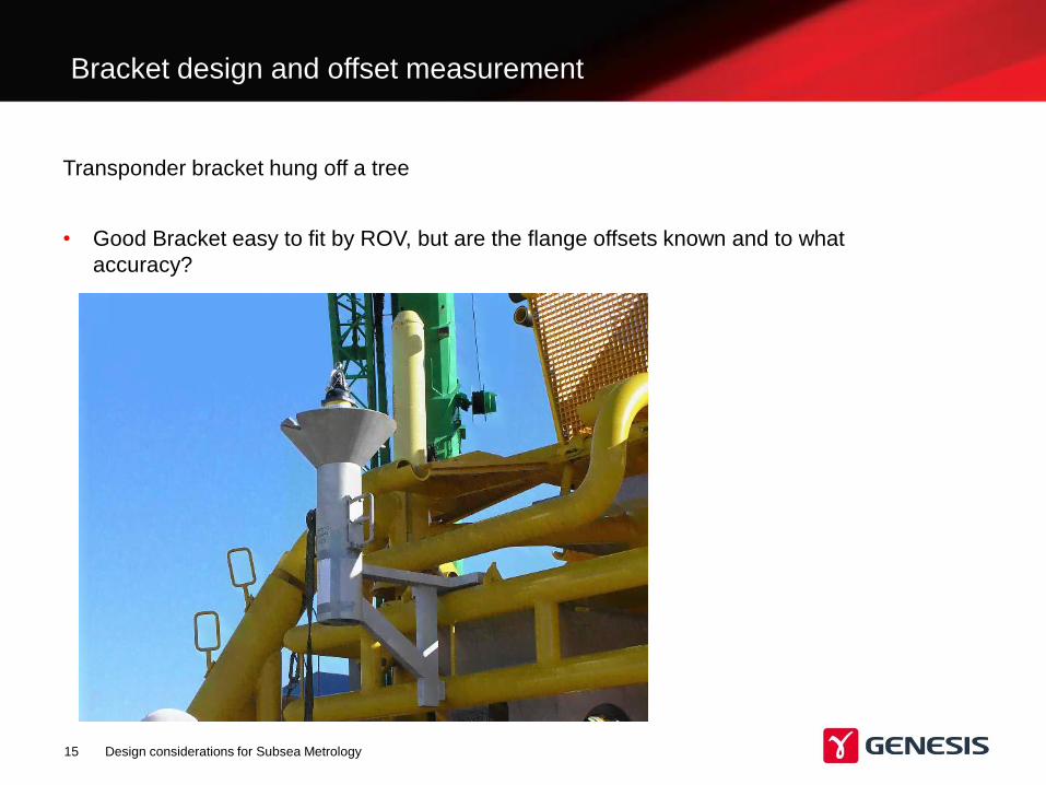
• Good Bracket easy to fit by ROV, but are the flange offsets known and to what
accuracy?
Transponder bracket hung off a tree
Design considerations for Subsea Metrology 15
Design considerations for Subsea Metrology 16
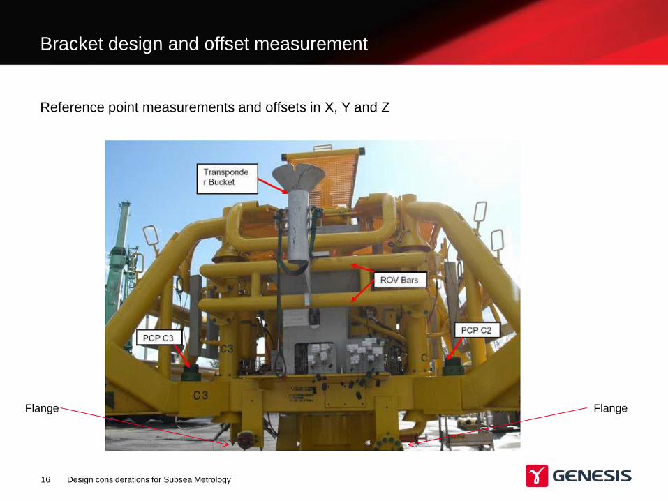
Reference point measurements and offsets in X, Y and Z
Flange Flange
Bracket design and offset measurement
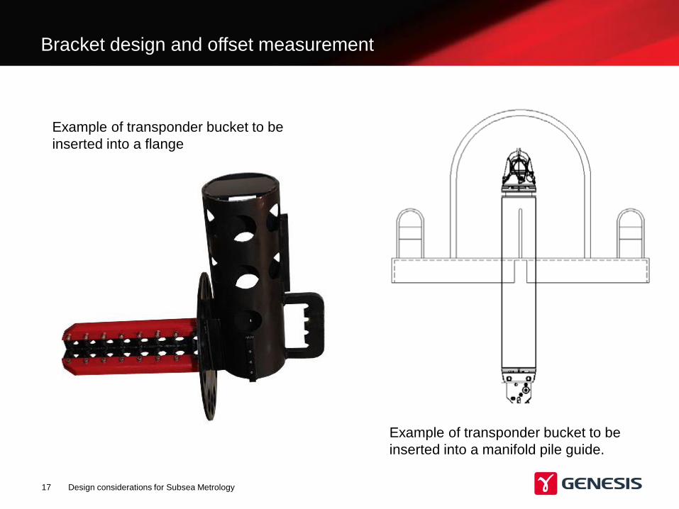
Example of transponder bucket to be
inserted into a flange
Design considerations for Subsea Metrology 17
Example of transponder bucket to be
inserted into a manifold pile guide.
Bracket design and offset measurement
• Early discussion on requirements with design engineers is required, surveyors to be
aware of the range of metrology tools that could provide the accuracy needed.
• If a measurement cannot be competently measured then the design has to change or
an alternative measuring system to accommodate is to be considered,
• If a project critical measurement has to me made then it should be given the planning
and time offshore to provide a successful measurement.
• The importance of brackets cannot be underestimated. Consider additional
measurements if reliant on ROV placing brackets
• Never use just one system to measure anything always use a coarse measurement
system to ensure no gross errors are made. This provides confidence in the
measurement.
• Always use two methods of calculating the correct measurement, I suggest Pre made
spread sheet with the estimated distance and Angles and AutoCAD.
Golden Rules for Metrology
Design considerations for Subsea Metrology 18
Design Considerations for Subsea metrology measurements
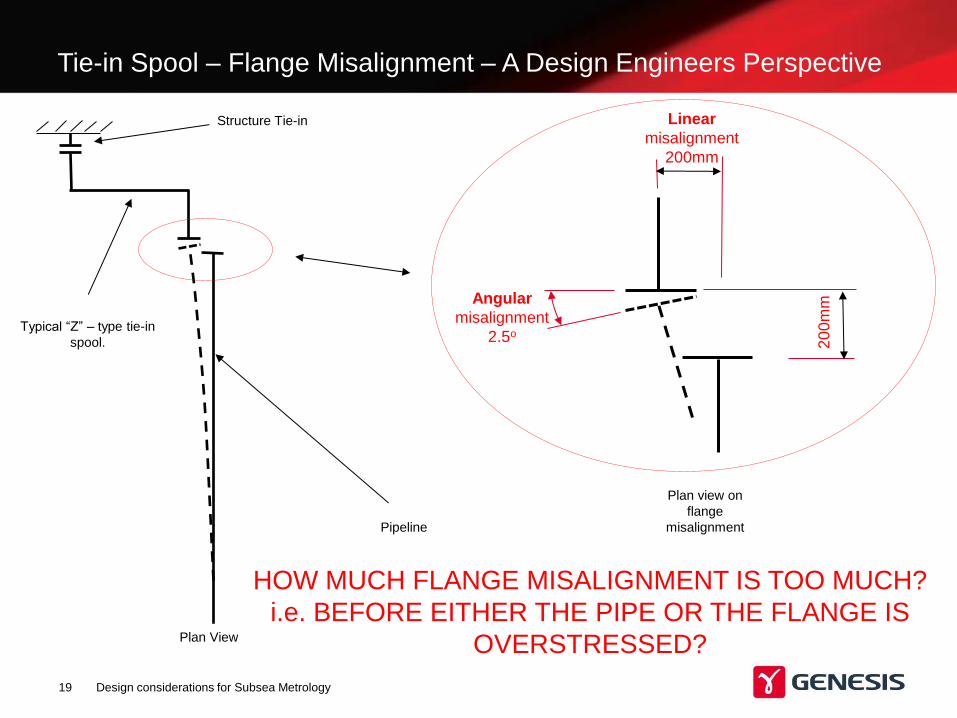
Tie-in Spool – Flange Misalignment – A Design Engineers Perspective
Design considerations for Subsea Metrology 19
Pipeline
20
0m
m
Linear
misalignment
200mm
Angular
misalignment
2.5o Typical “Z” – type tie-in
spool.
Structure Tie-in
Plan View
Plan view on
flange
misalignment
HOW MUCH FLANGE MISALIGNMENT IS TOO MUCH?
i.e. BEFORE EITHER THE PIPE OR THE FLANGE IS
OVERSTRESSED?
Design considerations for Subsea Metrology 20
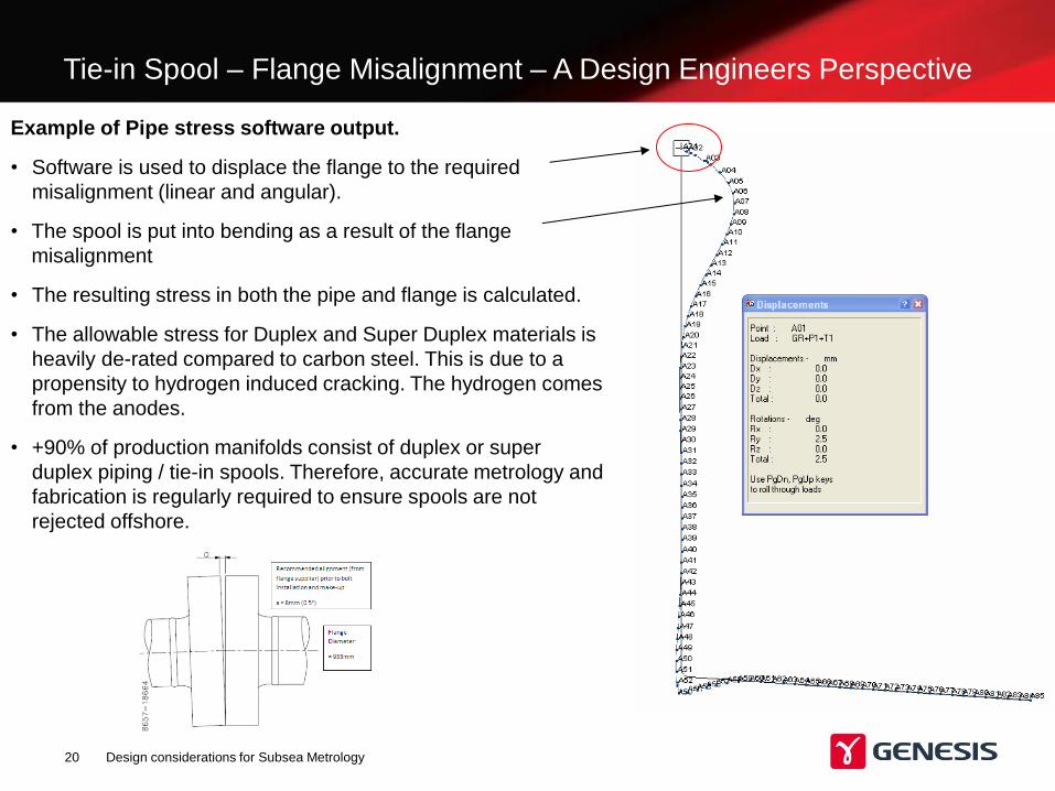
Example of Pipe stress software output.
• Software is used to displace the flange to the required
misalignment (linear and angular).
• The spool is put into bending as a result of the flange
misalignment
• The resulting stress in both the pipe and flange is calculated.
• The allowable stress for Duplex and Super Duplex materials is
heavily de-rated compared to carbon steel. This is due to a
propensity to hydrogen induced cracking. The hydrogen comes
from the anodes.
• +90% of production manifolds consist of duplex or super
duplex piping / tie-in spools. Therefore, accurate metrology and
fabrication is regularly required to ensure spools are not
rejected offshore.
Tie-in Spool – Flange Misalignment – A Design Engineers Perspective
Tie-in Spool – Flange Misalignment – A Design Engineers Perspective
Design considerations for Subsea Metrology 21
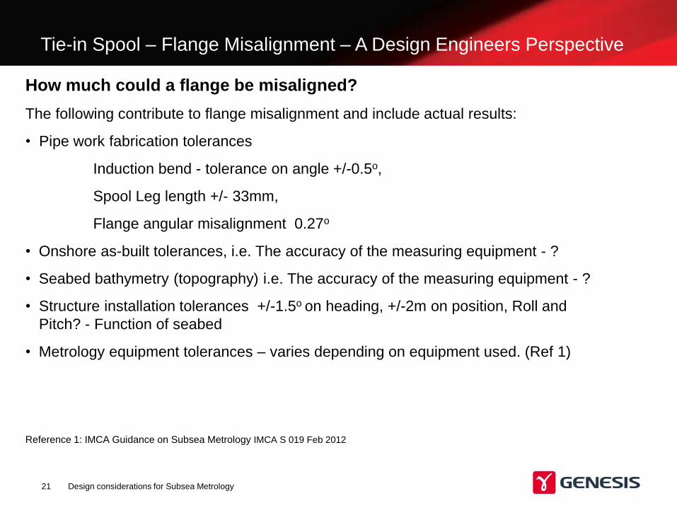
How much could a flange be misaligned?
The following contribute to flange misalignment and include actual results:
• Pipe work fabrication tolerances
Induction bend - tolerance on angle +/-0.5o,
Spool Leg length +/- 33mm,
Flange angular misalignment 0.27o
• Onshore as-built tolerances, i.e. The accuracy of the measuring equipment - ?
• Seabed bathymetry (topography) i.e. The accuracy of the measuring equipment - ?
• Structure installation tolerances +/-1.5o on heading, +/-2m on position, Roll and
Pitch? - Function of seabed
• Metrology equipment tolerances – varies depending on equipment used. (Ref 1)
Reference 1: IMCA Guidance on Subsea Metrology IMCA S 019 Feb 2012
Tie-in Spool – Flange Misalignment – A Design Engineers Perspective
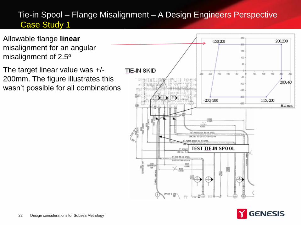
Case Study 1
Design considerations for Subsea Metrology 22
Allowable flange linear
misalignment for an angular
misalignment of 2.5o
The target linear value was +/-
200mm. The figure illustrates this
wasn’t possible for all combinations
Tie-in Spool – Flange Misalignment – A Design Engineers Perspective
Design considerations for Subsea Metrology 23
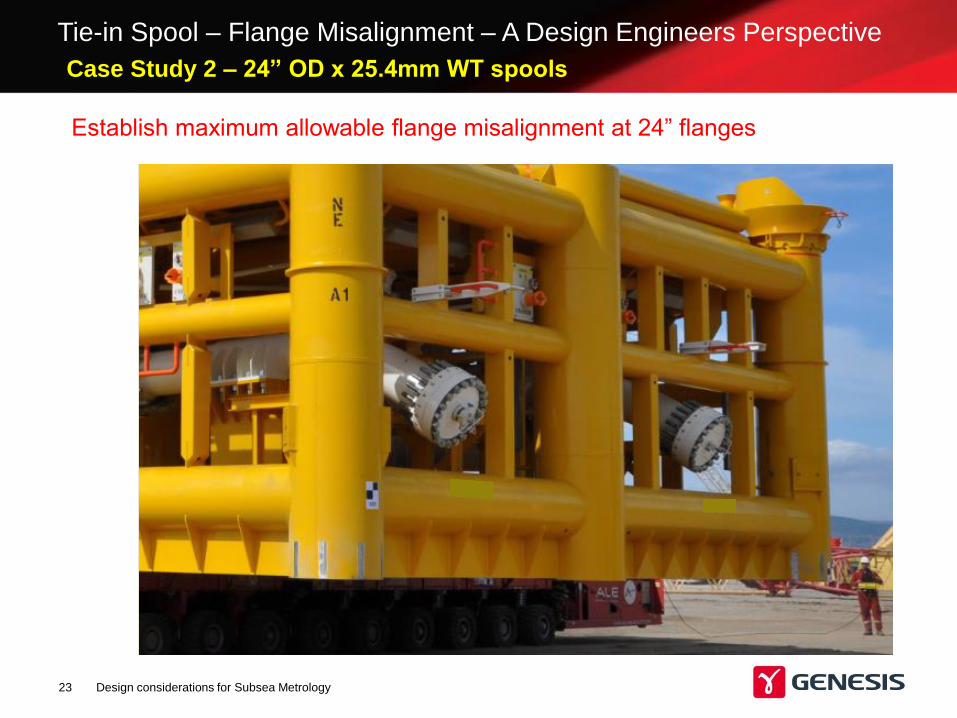
Establish maximum allowable flange misalignment at 24” flanges
Case Study 2 – 24” OD x 25.4mm WT spools
Design considerations for Subsea Metrology 24
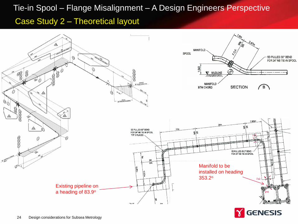
Existing pipeline on
a heading of 83.9o
Manifold to be
installed on heading
353.2o
Tie-in Spool – Flange Misalignment – A Design Engineers Perspective
Case Study 2 – Theoretical layout
Tie-in Spool – Flange Misalignment – A Design Engineers Perspective
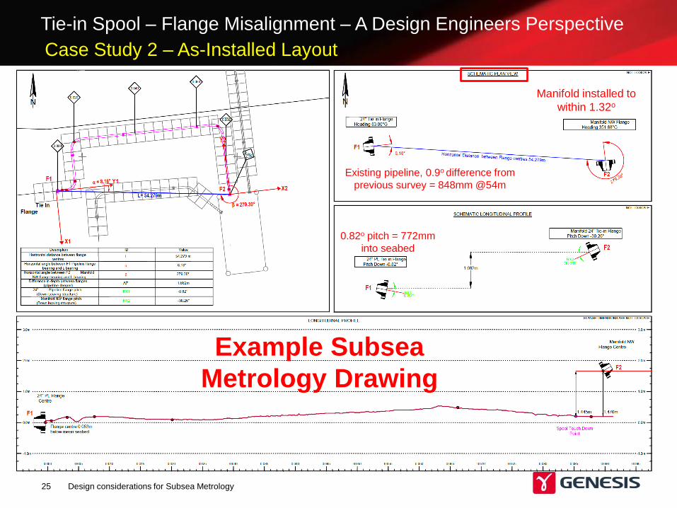
Design considerations for Subsea Metrology 25
Example Subsea
Metrology Drawing
Manifold installed to
within 1.32o
Existing pipeline, 0.9o difference from
previous survey = 848mm @54m
0.82o pitch = 772mm
into seabed
Case Study 2 – As-Installed Layout
Tie-in Spool – Flange Misalignment – A Design Engineers Perspective
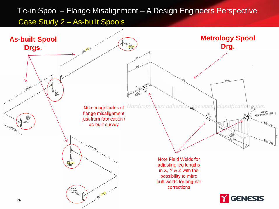
26
As-built Spool
Drgs.
Metrology Spool
Drg.
Note magnitudes of
flange misalignment
just from fabrication /
as-built survey
Note Field Welds for
adjusting leg lengths
in X, Y & Z with the
possibility to mitre
butt welds for angular
corrections
Case Study 2 – As-built Spools
Tie-in Spool – Flange Misalignment – A Design Engineers Perspective
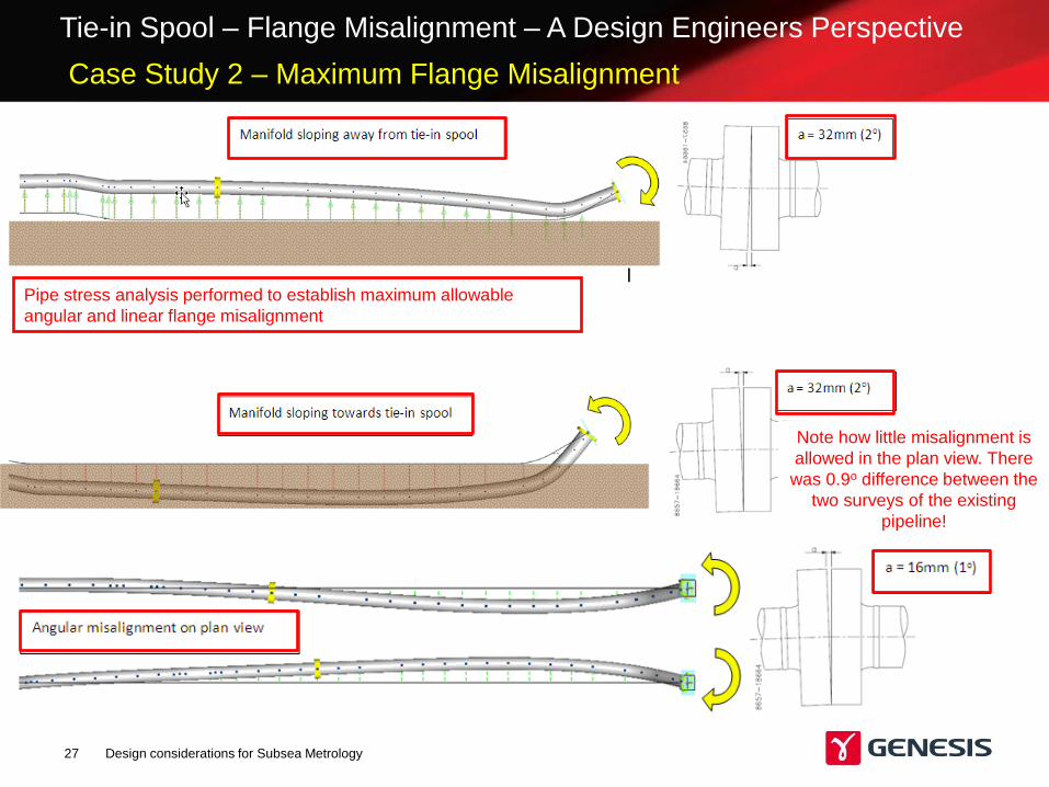
Design considerations for Subsea Metrology 27
Pipe stress analysis performed to establish maximum allowable
angular and linear flange misalignment
Note how little misalignment is
allowed in the plan view. There
was 0.9o difference between the
two surveys of the existing
pipeline!
Case Study 2 – Maximum Flange Misalignment
Tie-in Spool – Flange Misalignment – A Design Engineers Perspective
Design considerations for Subsea Metrology 28
What Can we Do Better?
• Better communication between all parties
e.g. metrology reports are rarely forwarded to design engineers.
Consequently, the design engineer has a very poor basis for typical
tolerances.
• Understand what magnitude of mitre fabricators can achieve at butt welds.
Induction bends are always manufactured in advance, therefore,
angular misalignment can only be taken out by mitring butt welds or
bending spools. DNV permits mitreing of butt welds up to 3o