spec proposal pa eu -...
TRANSCRIPT

APPLICATION GUIDELINAPPLICATION GUIDELINAPPLICATION GUIDELINAPPLICATION GUIDELINEEEE
SPECIFICATION PROPOSSPECIFICATION PROPOSSPECIFICATION PROPOSSPECIFICATION PROPOSAL FOR PROFIBUS PAAL FOR PROFIBUS PAAL FOR PROFIBUS PAAL FOR PROFIBUS PA BBBBased on international and European standardsased on international and European standardsased on international and European standardsased on international and European standards
PROFIBUS PA is used in a wide range of different
application. Typically for each application a dedicated
specification is required.
This document is a guideline regarding physical layer
parameters. It serves as a cookbook recipe for the
preparation of requests for proposals and quotations. It
provides guidelines so that constraints are met, which
have to be observed for successful planning of PROFIBUS
PA infrastructure. Special focus is given to application in
hazardous areas zone 0, 1 and 2.
This document is based on IEC and European standards
and directives like ATEX, EC etc.
Prepared by:
Thomas Klatt
Business Development Manager
Christian Ströhle
Manager Sales Support AP

Pepperl+Fuchs is the proven market leader for innovative and highly available components for your fieldbus ac-
cording to IEC 61158-2. With quality components to fit your process automation system and demands in the field
our highly reliable and energy-efficient design allows you to focus on the task at hand. Knowing that your fieldbus
is running.
The High-Power Trunk Concept with Entity or FISCO devices: Connect the maximum number of devices to the same
fieldbus trunk; and at the same time make use of maximum cable lengths. This concept utilizes standard power
supplies such as the easy to install and configuration free Power Hub. Segment Protectors and FieldBarriers are
installed close to field devices and limit the energy at the spur. You are free to work on field devices without hot
work permit.
Advanced Diagnostics: Take control of your fieldbus installation. This latest innovation brings transparency to
fieldbus. Speed up commissioning with automated documentation. Measure fieldbus performance and detect
changes in the control room before they become critical to your plants operation.
You can rely on products built to serve your every need in fieldbus for process automation. You can gain from the
experience of knowledgeable engineers to create your fieldbus solution. You can be at ease with products and
solutions from Pepperl+Fuchs.

Application Guideline Page 3 of 28
Spec_proposal_PA_EU 15.10.2008 10:24:29
1.1.1.1. ScopeScopeScopeScope ........................................................................................................................................................................................................................................................................................................................................4444
2.2.2.2. PurposePurposePurposePurpose............................................................................................................................................................................................................................................................................................................................4444
3.3.3.3. Definitions and AbbreviationsDefinitions and AbbreviationsDefinitions and AbbreviationsDefinitions and Abbreviations....................................................................................................................................................................................4444 3.1. Definitions.................................................................................................4
3.1.1. General .................................................................................................4 3.2. PROFIBUS PA Definitions .........................................................................4 3.3. Abbreviations ............................................................................................6
4.4.4.4. FIELDBUS SYSTEM OVERVIEWFIELDBUS SYSTEM OVERVIEWFIELDBUS SYSTEM OVERVIEWFIELDBUS SYSTEM OVERVIEW ............................................................................................................................................................................7777 4.1. Project Objectives.....................................................................................7 4.2. Overall System Configuration ..................................................................7
4.2.1. General .................................................................................................7 4.2.2. Integration of Control Function in DCS Controller ..............................8 4.2.3. Integrated Engineering Function in DCS .............................................8
5.5.5.5. FIELD SYSTEM DESIGN GUIDELINESFIELD SYSTEM DESIGN GUIDELINESFIELD SYSTEM DESIGN GUIDELINESFIELD SYSTEM DESIGN GUIDELINES............................................................................................................................ 10101010 5.1. General................................................................................................... 10 5.2. Fieldbus Application .............................................................................. 10 5.3. Field Device Selection ........................................................................... 11
5.3.1. Interoperability................................................................................... 11 5.3.2. Field Device Management ................................................................ 11 5.3.3. Field Device Power ............................................................................ 11 5.3.4. Device Upgrading .............................................................................. 12
5.4. Segment Coupler ................................................................................... 12 5.5. Segment Grouping................................................................................. 12 5.6. Segment cycle times ............................................................................. 12 5.7. Hazardous Area Classification.............................................................. 13 5.8. Critical Loop definition and Application................................................ 14
5.8.1. High Criticality Loop........................................................................... 14 5.8.2. Medium Criticality Loop..................................................................... 14 5.8.3. Low Criticality Loop............................................................................ 14
5.9. Redundancy ........................................................................................... 15 5.10. Physical Device Loading Requirements on PROFIBUS PA .................. 15
5.10.1. General Requirements ................................................................. 15 5.10.2. Requirements for Safe Area Application ..................................... 16 5.10.3. Requirements for Zone 2 application.......................................... 17 5.10.4. Requirements for Zone 1/ Zone 0 application ........................... 17
5.11. Segment Coupler Requirements .......................................................... 19 5.11.1. Additional Fieldbus Power Supply Requirements ....................... 19
5.12. Segment Spare Philosophy Requirements .......................................... 20 5.12.1. Segment Execution Time Requirements ..................................... 20
5.13. Segment Wiring Design Requirements ................................................ 21 5.13.1. Overall Wiring Design Philosophy ................................................ 21 5.13.2. Topology ........................................................................................ 21 5.13.3. Cable Type..................................................................................... 22 5.13.4. Cable Length ................................................................................. 22 5.13.5. Power Consumption ..................................................................... 23 5.13.6. Minimum Operating Voltage ........................................................ 23 5.13.7. Attenuation.................................................................................... 24 5.13.8. Example Calculation ..................................................................... 24 5.13.9. Segment Design Validation Tool .................................................. 26 5.13.10. Junction Box Requirements ......................................................... 26 5.13.11. Grounding of Shields .................................................................... 27 5.13.12. EMC protection ............................................................................. 27
Specification Proposal for PROFIBUS PA Page 4 of 28
1.1.1.1. ScopeScopeScopeScope This document
defines PROFIBUS PA system design requirements for the physical layer
gives information which additional requirements needs to be defined.
is based on international and European standards where hazardous area
applications are concerned.
2.2.2.2. PurposePurposePurposePurpose The purpose of the document is to define the PROFIBUS PA system design re-
quirements to:
Ensure consistency across the entire project.
Minimize the validation requirement.
Minimize commissioning related problem.
3.3.3.3. Definitions and AbbreviationsDefinitions and AbbreviationsDefinitions and AbbreviationsDefinitions and Abbreviations
3.1.3.1.3.1.3.1. DefinitionsDefinitionsDefinitionsDefinitions
3.1.1.3.1.1.3.1.1.3.1.1. GeneralGeneralGeneralGeneral
Shall refers to a mandatory requirement
Should refers to a recommendation
May refers to one acceptable course of action
3.2.3.2.3.2.3.2. PROFIBUS PA DefinitionsPROFIBUS PA DefinitionsPROFIBUS PA DefinitionsPROFIBUS PA Definitions The following table explains definitions of Fieldbus terms used within this proce-
dure.
Term Definition
Bus A Fieldbus cable between a host and field devices
connected to multiple segments, normally through
the use of repeaters.
Control loop A Control loop contains all field instruments which
are needed to close the loop (Sensor and actuator).
E.g. Pressure transmitter and valve.
DP/PA gateway A device which converts the PROFIBUS DP protocol
to PROFIBUS PA protocol. It adopts e.g. transmis-
sion speed and converts from an asynchronous to
synchronous telegram format.
DP Slave A field device which is directly connected to
PROFIBUS DP.
Terms and definitions:

Application Guideline Page 5 of 28
Spec_proposal_PA_EU 15.10.2008 10:24:29
Term Definition
Fieldbus A Fieldbus is a digital, two-way, multi-drop commu-
nication link among intelligent measurement and
control devices. It serves as a Local Area Network
(LAN) for advanced process control, remote in-
put/out and high-speed factory automation applica-
tions.
Fieldbus Power
Supply
A device which switches the power supply onto the
PROFIBUS PA cable. All PA devices will be powered
from this device.
FISCO
Fieldbus Intrinsi-
cally Safe Concept
Allows more power to an IS segment for approved
FISCO devices, allowing for more devices per IS
segment. Avoids the need to calculated inductances
and capacitances for the proof of intrinsic safety.
Interchangeability Interchangeability is the capability to substitute a
device from one manufacturer with that of another
manufacturer on a Fieldbus network without loss of
functionality or degree of integration.
Master class 1 PROFIBUS DP Master which is typically responsible
for the cyclic data exchange of process variables.
Typically it is a part of the CPU
Master class 2 PROFIBUS DP Master which is typically used for con-
figuration and parameterization of field devices.
Additionally it will be used for maintenance purposes
and will be linked or is a part of the Asset Manage-
ment System. typically it is a PC or Workstation with
an integrated PROFIBUS DP interface.
Monitoring loop Contains Field devices whose values are not used in
control loops.
PA device (Fieldbus
device)
A field device which is connected directly to a
PROFIBUS PA fieldbus.
Segment A Segment is a section of a fieldbus that is termi-
nated in its characteristic impedance. Segments can
be linked by devices to form a longer fieldbus seg-
ment.
Segment Coupler A device which converts from PROFIBUS DP to
PROFIBUS PA and vice versa. Typically it consist of a
DP/PA gateway and Fieldbus Power Supplies.
Spur A Spur is a fieldbus branch line connecting to the
trunk that is a final circuit.
Terminator A Terminator is an impedance-matching module used at or near each end of a transmission line. Two Terminators must be used on each fieldbus segment.
Topology The Segment structure; Tree, Daisy Chain, etc. are ex-amples.
Transmitter A Transmitter is an active PROFIBUS PA device contain-ing circuitry, which applies a digital signal on the bus.

Specification Proposal for PROFIBUS PA Page 6 of 28
Term Definition
Trunk/Home-run A Trunk is the main communication highway between devices on an PROFIBUS PA network. The Trunk acts as source of main supply to Spurs on the network.
Table 1: List of used terms
3.3.3.3.3.3.3.3. AbbreviationsAbbreviationsAbbreviationsAbbreviations The following list gives the used abbreviations in this document.
Abbreviations Description
AI Analog Input
AO Analog Output
AWG American Wire Gauge
CCR Central Control Room
CPU Central Processing Unit
DCS Distributed Control System
DI Discrete Input
DD Device Description
DO Discrete Output
DTM Device Type Manager
EI Early Involvement
EC Engineering Contractor
FCS Field Control Station
FCU Field Control Unit
FDT Field device Tool
FGS Fire & Gas Detection System
FISCO Fieldbus Intrinsic Safety Concept
FPS Fieldbus Power Supply
GSD, GSE Geraetestammdatendatei, a form of electronic data
sheet which is required for configuration of the cyclic
data exchange.
HART Highway Addressable Remote Transmitter
HIS Human Interface Station with having system builder
function
I/O Input/Output
Abbreviations:

Application Guideline Page 7 of 28
Spec_proposal_PA_EU 15.10.2008 10:24:29
Abbreviations Description
IS Intrinsic Safety
LAN Local Area Network
MOV Motor Operated Valve
MVC Transmitter Measurement, Validation & Comparison
PID Proportional/Integral/Derivative Control
PMC Project Management Contractor
PLC Programmable Logic Controller
PRM Plant Resource Manager
RIO Remote I/O system
UOM Units of Measurements
SIS Safety Instrumented system
UPS Uninterrupted Power Supply
Table 2: List of abbreviations
4.4.4.4. FIELDBUS SYSTFIELDBUS SYSTFIELDBUS SYSTFIELDBUS SYSTEM OVERVIEWEM OVERVIEWEM OVERVIEWEM OVERVIEW
4.1.4.1.4.1.4.1. Project ObjectivesProject ObjectivesProject ObjectivesProject Objectives The Distributed Control System should be based on the Open System Architecture
concept with PROFIBUS interfacing capabilities to smart devices in the field.
Key driver for this technology is the ability to realize an infrastructure that is ready
to implement diagnostics/advanced diagnostics and asset management capabili-
ties and to be prepared for predictive/proactive maintenance. Guidelines provided
in this document are intended to design the Fieldbus based system with minimum
risks and no errors.
4.2.4.2.4.2.4.2. Overall System ConfigurationOverall System ConfigurationOverall System ConfigurationOverall System Configuration
4.2.1.4.2.1.4.2.1.4.2.1. GeneralGeneralGeneralGeneral
A Fieldbus system refers to a control system that uses a digital, two-way, multi-
drop communication link among intelligent measurement and control devices. It
serves as a Local Area Network (LAN) for advanced process control, remote I/O
and high-speed factory automation applications. With the DCS system, it is possi-
ble to build a Fieldbus system according to the Process Automation requirements
and to operate and monitor processes in the same manner as conventional solu-
tions did in the past.
The following figure shows a typical PROFIBUS structure:

Specification Proposal for PROFIBUS PA Page 8 of 28
CPU
Master class 1
T T
Master class 2
4 PROFIBUSPA segments
DP Slave
RIO
conventional4 - 20mA ordigital signals
PROFIBUS DP
Figure 1: Typical PROFIBUS structure
4.2.2.4.2.2.4.2.2.4.2.2. Integration of Control Function in DCS ControllerIntegration of Control Function in DCS ControllerIntegration of Control Function in DCS ControllerIntegration of Control Function in DCS Controller
PROFIBUS is using a hybrid access procedure, a mixture of Master/Slave and
Token passing procedure.
All process variables will be transmitted to the Master class 1 which is part of the
CPU. The CPU is a part of the PLC or DCS system. Depending on this all control
related functions are an integral part of the PLC or DCS.
4.2.3.4.2.3.4.2.3.4.2.3. Integrated Integrated Integrated Integrated Engineering Function in DCSEngineering Function in DCSEngineering Function in DCSEngineering Function in DCS
The DCS shall be able to integrate the fieldbus system functions, such as configu-
ration of PROFIBUS DP/PA segments, integration of DP and PA devices and con-
trol drawings containing function blocks.
In addition, a Plant Resource Manager (PRM) or Asset Management function shall
be provided. This function is not directly related to above engineering, operation
and monitoring functions, but is a maintenance related function with long-term
data storage capability.
These functions will efficiently handle PROFIBUS device maintenance manage-
ment.
Such systems also supports traditional analog devices, Remote I/O systems and
HART devices and can provide integrated management of PROFIBUS and HART
devices.
Application Guideline Page 9 of 28
Spec_proposal_PA_EU 15.10.2008 10:24:29
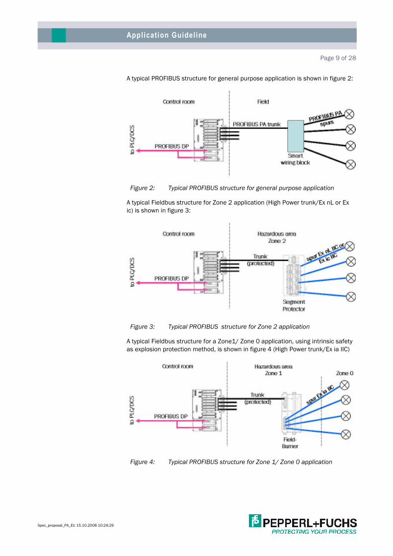
A typical PROFIBUS structure for general purpose application is shown in figure 2:
Figure 2: Typical PROFIBUS structure for general purpose application
A typical Fieldbus structure for Zone 2 application (High Power trunk/Ex nL or Ex
ic) is shown in figure 3:
Figure 3: Typical PROFIBUS structure for Zone 2 application
A typical Fieldbus structure for a Zone1/ Zone 0 application, using intrinsic safety
as explosion protection method, is shown in figure 4 (High Power trunk/Ex ia IIC)
Figure 4: Typical PROFIBUS structure for Zone 1/ Zone 0 application

Specification Proposal for PROFIBUS PA Page 10 of 28
5.5.5.5. FIELD SYSTEM FIELD SYSTEM FIELD SYSTEM FIELD SYSTEM DESIGN GUIDELINESDESIGN GUIDELINESDESIGN GUIDELINESDESIGN GUIDELINES
5.1.5.1.5.1.5.1. GeneralGeneralGeneralGeneral PROFIBUS PA is an all-digital, serial, two-way communication protocol that con-
nects field devices (instruments), such as sensors, actuators, and controllers.
PROFIBUS PA enables advanced diagnostics from all fieldbus components includ-
ing the physical layer. This allows higher plant availability. A typical Fieldbus instal-
lation provides connection from a network of field devices via a segment coupler
to a host system via a two way, serial communication link. The cabling and con-
nections are arranged in a multi-drop fashion, requiring only a single pair cable
with parallel connections to field devices. PROFIBUS PA is different from the tradi-
tional approach of connecting 4 to 20 mA devices to a DCS/PLC system using
dedicated pairs of wires for each device.
Each Fieldbus running from the segment coupler to the field is known as a seg-
ment (see figure 2 to figure 4). Each segment consists of a trunk or home-run,
running from the segment coupler to the processing plant with parallel connected
spurs linking to field devices such as transmitters and control valves. Smart wiring
blocks with integrated short circuit protection, such as Segment Protectors or
FieldBarriers, protect the trunk against short circuit on a spur. Such protectors are
preferred to connect the individual instruments to the trunk.
The interconnection from a PROFIBUS PA trunk to PROFIBUS DP is realized with a
segment coupler. The segment coupler
converts the PROFIBUS PA physics based on the IEC 61158-2 to the
PROFIBUS DP physics based on RS 485.
adapts the transmission speed of 31.25 kbit/s (PROFIBUS PA) to the ad-
justed transmission speed of PROFIBUS DP (9.6 kbit/s to 12 Mbit/s).
converts the synchronous data transmission of PROFIBUS PA to asyn-
chronous data transmission of PROFIBUS DP
All above described functionalities are working from PROFIBUS PA to PROFIBUS
DP and vice versa.
Additional the segment coupler provides conditioned power to the trunk and all
devices on the PROFIBUS PA segment.
5.2.5.2.5.2.5.2. Fieldbus ApplicationFieldbus ApplicationFieldbus ApplicationFieldbus Application The use of PROFIBUS PA shall be maximized for all regulatory process control
devices where a suitable PA device is available and in addition, shall also apply to
all Packaged Equipment (except in those packages with their own PLC).
PROFIBUS PA shall not be used for the following applications:
Emergency Shut Down System and Fire & Gas Detection System signals
due to safety reasons.

Application Guideline Page 11 of 28
Spec_proposal_PA_EU 15.10.2008 10:24:29
5.3.5.3.5.3.5.3. Field Device SelectionField Device SelectionField Device SelectionField Device Selection
5.3.1.5.3.1.5.3.1.5.3.1. InteroperabilityInteroperabilityInteroperabilityInteroperability
PROFIBUS PA devices must be interoperable with the DCS/PLC. This eliminates
the proprietary protocols and custom software drivers and maximizes the benefits
of the advanced diagnostic features of Fieldbus. To ensure full interoperability, all
PA devices shall be supplied with the gsd and, if required, the DD file or DTM and
firmware revisions.
Based on the above objective, the following selection method shall be applied for
PA devices excluding valve positioners (in order of preference):
1st Selection DCS PA devices.
2nd Selection Other PA devices.
Similarly, the selection method for valve positioners shall be as follows (in order of
preference).
1st Selection valve positioner from other vendors
2nd Selection DCS valve positioner
Any other PA device and/or positioner shall, as a minimum, have the following
features available:
PROFIBUS PA Certification
The PA Device shall be capable of performing continuous diagnostics, in-
cluding self-test functions, to provide specific diagnostic information to
the Asset Management System.
In addition a sample device of each instrument type shall be submitted to
DCS/PLC Supplier for interoperability testing with both the DCS/PLC and Asset
Management System. On successful completion of these tests, the DCSPLC ven-
dor or EC shall provide the necessary approval for use and shall update the “Ap-
proved Device Listing”.
The DCS/PLC vendors are responsible for getting all necessary data for the "Inter-
operability Tests" and coordinating with the instrument vendors to successfully
complete the tests.
5.3.2.5.3.2.5.3.2.5.3.2. Field Device ManagementField Device ManagementField Device ManagementField Device Management
Each device's fieldbus address and Physical Device (PD) Tag must be set prior to
installation to enable connection of multiple devices during construction and
commissioning. Either the Device manufacturer prior to shipment or the Subcon-
tractor prior to connection shall do this.
5.3.3.5.3.3.5.3.3.5.3.3. Field Device PowerField Device PowerField Device PowerField Device Power
PROFIBUS PA devices are normally powered from the segment. Bus-powered de-
vices typically require 10-25 mA of current at between 9 and 32 volts, but devices
requiring more than 25 mA shall be subject to approval.
PA devices can be polarity sensitive and therefore wiring polarity shall be main-
tained for all devices.

Specification Proposal for PROFIBUS PA Page 12 of 28
5.3.4.5.3.4.5.3.4.5.3.4. Device UpgradingDevice UpgradingDevice UpgradingDevice Upgrading
PA device firmware changes can be made while the hardware is left unchanged.
To accommodate easy device upgrading, devices shall be specified with flash
memory capabilities, so that upgrades can be done on-line.
Furthermore, it is important to document each devices GSD and DD or DTM revi-
sion.
5.4.5.4.5.4.5.4. Segment CouplerSegment CouplerSegment CouplerSegment Coupler The segment coupler is the core of every PROFIBUS PA installation. The functional-
ities are described in General. Typically a Segment Coupler consists of a (redun-
dant) gateway and separate fieldbus power supply modules. When required the
fieldbus power supply modules could be redundant
To avoid any problems in terms of
Availability
PROFIBUS PA cycle time
Limitation in data volume to be transmitted via the Segment Coupler.
Communication between Master class 1 or Master class 2 and a PA de-
vices
the Segment Coupler shall support the following functionalities:
Transparent communication between Master class 1 or Master class 2
and PROFIBUS PA devices.
Single or redundant gateway
One integrated PROFIBUS PA Master per segment. In case of a redundant
gateway the integrated PROFIBUS PA master shall also be redundant.
Single or redundant fieldbus power supply module(s) per segment.
5.5.5.5.5.5.5.5. Segment GroupingSegment GroupingSegment GroupingSegment Grouping In order to maximize the benefits of the PA technology, all devices of a particular
loop should be connected to the same PROFIBUS DP master class 1. However, in
order to minimize the effect, this is not a mandatory requirement, but shall be
followed where possible, without incurring excessive cable run lengths.
5.6.5.6.5.6.5.6. Segment cycle timesSegment cycle timesSegment cycle timesSegment cycle times The PROFIBUS PA cycle times need to be defined. Up to 70% of the cycle time
could be used for cyclic data exchange and at least 30% of the cycle time should
be free for acyclic communication.
The cycle times depend on
The process
Number of instruments in the segment
Type of loop
The following differentiation between type of loops is recommended:
Control loops

Application Guideline Page 13 of 28
Spec_proposal_PA_EU 15.10.2008 10:24:29
Monitoring loops
Segments containing control loops should have a shorter cycle time than seg-
ments which only contain monitoring loops. An approximately calculation of the
PROFIBUS PA Segment cycle time could be done by using the following equation:
tPA_cycle = n * (0.256 ms * L +12 ms) + 40 ms
with
tPA_cycle = PROFIBUS PA cycle time
n = Number of connected PA instruments on this segment
L = The effective data length. L is a unit less variable calculated as the
average input and output data quantity (in bytes) of all devices.
ExampExampExampExample:le:le:le: In case of 20 PA instruments connected to a single segment and each
instrument is transmitting 5 Byte data, independent of input or output, the PA
cycle time will be approximately 305.6 ms.
5.7.5.7.5.7.5.7. Hazardous Area ClassificationHazardous Area ClassificationHazardous Area ClassificationHazardous Area Classification Hazardous area protection depends on the application and shall be as follows:
Zone 0Zone 0Zone 0Zone 0
Intrinsic Safety shall be the preferred explosion protection method for
Zone 0 applications. The field device shall be marked accordingly. Mini-
mum requirement is
Ex ia IIC (Temperature class must be defined).
Zone 1Zone 1Zone 1Zone 1
Intrinsic Safety shall be the preferred explosion protection method for
Zone 1 applications. The field device shall be marked accordingly. Mini-
mum requirement is
Ex ib IIC, better Ex ia IIC (Temperature class must be defined).
Zone 2Zone 2Zone 2Zone 2
Intrinsic Safety shall be the preferred explosion protection method for
Zone 2 applications. The field device shall be marked accordingly. Mini-
mum requirement is
Ex ic IIC, better Ex ia IIC or Ex ib IIC (Temperature class must be defined).
Energy limitation (Ex nL) can be used where intrinsic safety is not psooi-
ble. The field device shall be marked accordingly. Minimum requirement
is Ex nL IIC better Ex ia/ib/ic IIC.
In July 2006 the 5th edition of the IEC 60079-11 was published. This edition con-
tains the type of protection “Ex ic” as an alternative to “Ex nL” according to the 3rd
edition of IEC 60079-15 for Zone 2 application. Due to harmonization “Ex nL”
remains in the 3rd edition of IEC 60079-15 for an interim time until the 4th edition
is published (probably in 2011) but will not be a part of the 4th edition anymore.
Under the aspects of the ATEX directive 94/4/EC as a consequence vendors are
Attention:

Specification Proposal for PROFIBUS PA Page 14 of 28
not allowed to sell new “Ex nL” components after the 4th edition of IEC 60079-15
has been published. Just replacement business can be maintained.
It is strongly recommended (if available) to use “Ex ic” or higher classified compo-
nents for Zone 2 application to avoid in future any trouble with spare parts and/or
further extensions, since it is expected that device vendors will switch soon their
product portfolio to “Ex ic” compliant devices. In case “Ex nL” instrumentation will
be used the installation shall be prepared for the “Ex ic” enhancements in the
near future. One installation aspect is for example that “Ex nL/Ex ic” wires shall be
installed separated from non-intrinsically safe ones.
Intrinsic Safety and Energy Limitation are the only explosion protection methods
which allow live maintenance on the spur without additional, mechanical explo-
sion protection methods or gas clearance certificate.
All devices shall be at least ATEX, Factory Mutual, UL, CSA and/or CUL or compa-
rable certified and labeled for the required area classification where they will be
installed.
To reduce the required proof of intrinsic safety down to the absolute minimum
FISCO certified field devices are preferred, when FISCO devices are not available
Entity certification will also be accepted. To keep the selection of the appropriate
barrier for Zone 1/ Zone 0 applications simple, the barrier outputs shall be certi-
fied in accordance to FISCO andandandand Entity.
5.8.5.8.5.8.5.8. Critical Loop definition and ApplicationCritical Loop definition and ApplicationCritical Loop definition and ApplicationCritical Loop definition and Application In an application there are typically loops available with different levels of critical-
ity. These levels need to be defined. The following paragraphs can be recognized
as an example.
The level of criticality shall be shown on both the segment and loop drawings.
5.8.1.5.8.1.5.8.1.5.8.1. High Criticality LoopHigh Criticality LoopHigh Criticality LoopHigh Criticality Loop
A failure of a high criticality loop will result in a total system trip, causing a shut-
down of the entire unit, or other unavoidable losses in excess of e.g. $10M. Nor-
mal positioner failure mode is to be used for this classification.
5.8.2.5.8.2.5.8.2.5.8.2. Medium Criticality LoopMedium Criticality LoopMedium Criticality LoopMedium Criticality Loop
Failure of a medium criticality loop will result in a total system trip, causing a shut-
down of the entire unit, or other unavoidable losses in excess of e.g. $100K. How-
ever, the medium criticality loop positioners’ process dynamics allow time for
quick recovery from the failure, either by quickly fixing a fault or by taking manual
control. The difference in high and medium criticality loops are dependent on
operations ability to respond to a single failure.
5.8.3.5.8.3.5.8.3.5.8.3. Low Criticality LoopLow Criticality LoopLow Criticality LoopLow Criticality Loop
Failure of this Positioner will not result in any short-term risk of total unit shut-
down or major operating losses. Low criticality loop valves can go to their fail posi-
tion without requiring immediate operator action.
Definition:
Definition:
Definition:

Application Guideline Page 15 of 28
Spec_proposal_PA_EU 15.10.2008 10:24:29
5.9.5.9.5.9.5.9. RedundancyRedundancyRedundancyRedundancy Redundancy is required at least for segments which contain high criticality loops.
To enhance the overall availability the following redundant equipment shall be
incorporated within the host system, DCS, EC:
Redundant DCS Bulk Power Supplies with 30-minute battery backup
(UPS).
Redundant DCS System Controller Power Supplies.
Redundant DCS System Controllers.
Redundant Master class 1 as preferred option (not mandatory).
Redundant PROFIBUS PA Power Supplies / Power Conditioners serving 1
segment per pair of Power Supplies/Power Conditioners as a preferred
option.
Redundant PROFIBUS PA Master
Additionally at least segments which contain high criticality loops shall be moni-
tored continuously by an advanced physical layer diagnostic module.
5.10.5.10.5.10.5.10. Physical Device Loading Requirements oPhysical Device Loading Requirements oPhysical Device Loading Requirements oPhysical Device Loading Requirements onnnn PROFIBUS PAPROFIBUS PAPROFIBUS PAPROFIBUS PA
5.10.1.5.10.1.5.10.1.5.10.1. General RequirementsGeneral RequirementsGeneral RequirementsGeneral Requirements
PROFIBUS PA supports up to 32 devices per segment. This includes the PA Master
integrated in the Segment Coupler. The field devices shall be bus powered by the
fieldbus cable.
There are limitations which need to be observed:
DCS/PLC related limitations
Physical layer related limitations
5.10.1.1.5.10.1.1.5.10.1.1.5.10.1.1. DCSDCSDCSDCS/PLC/PLC/PLC/PLC related limitations related limitations related limitations related limitations
The DCS/PLC could limit
The Number of addressable nodes. Typically PROFIBUS supports the ad-
dress range from 0 to 127. Address 127 is a broadcast message which is
not usable as a device address. Address 126 is the default address of
every PROFIBUS PA device. Therefore this address shall also not be used
for normal operation to ensure an easy exchange of a PROFIBUS PA in-
strument. When address 126 is not in use a new PA instrument could be
readdressed via the bus.
Depending on this there are 126 (address range 0 to 125) addresses free
for use. This includes the addresses of all PROFIBUS DP Master (Master
class 1 and 2).
It is recommended to use address 0 for Master class 2 (maintenance sta-
tion) and the addresses 1 and 2 for Master class 1. This address setting
will cover also the case of a redundant Master class 1.
The addresses of the (redundant) PROFIBUS PA Master must NOTNOTNOTNOT be
taken into account because these addresses are not visible on the
PROFIBUS DP side. Typically the default addresses of the PROFIBUS PA
Master are 1 (main master) and 2 (redundant master). This avoids also

Specification Proposal for PROFIBUS PA Page 16 of 28
any conflicts with field device addresses, independent of if the devices
are connected to PROFIBUS DP or PROFIBUS PA.
Amount of data per PROFIBUS telegram. PROFIBUS supports up to 244
bytes per telegram. The PROFIBUS DP master shall support this data vol-
ume.
These limitations have to be observed.
5.10.1.2.5.10.1.2.5.10.1.2.5.10.1.2. Physical Layer related limitationsPhysical Layer related limitationsPhysical Layer related limitationsPhysical Layer related limitations
Field devices shall be supplied from the fieldbus cable. The average current,
drawn by the field devices connected to the same segment is, depending on the
type of field devices, between 12 mA and 18 mA per field devcie.
Depending on the limitations explained in chapter 5.10.1.1, it is not recom-
mended to connect more than 22 field devices per segment (including required
spare see Segment Spare Philosophy Requirements). To avoid any additional
limitations, the Fieldbus Power Supply shall support a supply current of at least
500 mA.
In case it is ensured that the required supply current per segment is less or equal
to 350mA (including required spare) Fieldbus Power Supplies with a supply cur-
rent of 360mA are acceptable.
An additional limitation is given by the IEC 61158-2 standard. This standard de-
fines the maximum spur cable length as a function of connected nodes to the
segment. The PROFIBUS PA master(s) counts as a node. The following table shows
the definition made within the IEC standard:
Number of addresses
in use
Maximum spur cable
length
1 -12 120m
13 - 14 90m
15 - 18 60m
19 - 24 30m
25 - 32 ≤ 1m
Table 3: Maximum spur cable length in accordance to IEC 61158-2.
5.10.2.5.10.2.5.10.2.5.10.2. Requirements for Safe Area ApplicationRequirements for Safe Area ApplicationRequirements for Safe Area ApplicationRequirements for Safe Area Application
To avoid a breakdown of the entire segment due to a short on a spur or a field
device, the Wiring Blocks shall support short circuit protection (Segment Protec-
tors). The Segment Protectors shall support a supply current of 40mA and the
short circuit current shall be limited to no more than 60mA.
In case of a distributed segment architecture (two or more Segment Protectors
per segment) the trunk shall be able to be disconnected without interrupting the
communication to the following Segment Protectors.

Application Guideline Page 17 of 28
Spec_proposal_PA_EU 15.10.2008 10:24:29
5.10.3.5.10.3.5.10.3.5.10.3. Requirements for Zone 2 applicationRequirements for Zone 2 applicationRequirements for Zone 2 applicationRequirements for Zone 2 application
To avoid limitations in the no. of connectable field devices standard Fieldbus
Power Supplies with a minimum supply current of 360mA (500mA) shall be used.
The trunk shall be installed in accordance with IEC 60079-14.
The IEC 60079-14 standard defines the following installation requirements for
Zone 1 andandandand Zone 2 applications:
The cable needs to be protected against
o mechanical damaging
o chemical influences
o corrosion
o effects of heat
Allowed cable materials are
o Thermoplastic sheathed cables
o Thermosetting sheathed cables
o Elastomeric sheathed cables
o Mineral insulated metal sheathed cables, e.g. armored cables.
To allow a simple live maintenance capability the field devices shall be certified
Ex nL or Ex i. The Segment Protectors shall be certified Ex nA [ic] or Ex nA [L]. The
requirements given in chapter 5.10.2 are also valid for Zone 2 application.
5.10.4.5.10.4.5.10.4.5.10.4. Requirements for Zone 1/ Zone 0 applicationRequirements for Zone 1/ Zone 0 applicationRequirements for Zone 1/ Zone 0 applicationRequirements for Zone 1/ Zone 0 application
There are two solutions available for Zone 1/ Zone 0 applications
High Power Trunk concept
Full FISCO solution
The following figures show the structures of both solutions:
Figure 5: Structure High Power Trunk Concept

Specification Proposal for PROFIBUS PA Page 18 of 28
Figure 6: Structure Full FISCO System
The typical supply current of FISCO compatible Segment Coupler (EEx ia IIC) is
100mA. The typical supply voltage of this component is 12.8 vdc. These limita-
tions do mean:
The number of field devices per segment is reduced (depending on the
real current consumption of the field devices down to 4 to 8). This would
require more Fieldbus Power Supplies compared to the High Power Trunk
concept
the max. cable length is reduced. This depends on the low supply voltage
of a FISCO power supply
typically short circuit protection for the spurs is not supported. The reason
is that the wiring blocks with short circuit protection causes an additional
voltage drop which reduces the max. cable length additionally.
In practice and in order to minimize the Fieldbus validation and commissioning
related problems, High Power trunk concept with FieldBarriers shall be used.
FieldBarriers will be powered via standard Fieldbus Power Supplies. The trunk
needs to be installed in accordance to IEC 60079-14 (for details please refer to
chapter 5.10.3).
The number of FieldBarriers shall be limited to four.
The FieldBarrier works as an IS barrier. The outputs of this barrier shall be [EEx ia]
IIC certified. This will at least allow live maintenance on the field device level.
To avoid any additional limitations the FieldBarrier outputs shall be certified in
acc. to FISCO anananand/ord/ord/ord/or Entity. The outputs shall be short circuit limited with a short
circuit current no more than 50mA.
Additional it is recommended that the FieldBarrier is DIN rail mountable. Then it
could be easily mounted in any project specific enclosure.

Application Guideline Page 19 of 28
Spec_proposal_PA_EU 15.10.2008 10:24:29
5.11.5.11.5.11.5.11. Segment CouSegment CouSegment CouSegment Coupler Requirementspler Requirementspler Requirementspler Requirements To avoid limitations on overall cable length the Fieldbus Power Supplies, which are
part of the Segment Coupler, shall support high output voltage. PA field devices
are working within the voltage range from 9 vdc ... 32 vdc.
Typical FPS’s are offering a supply voltage of 28Vdc at 500mA supply current. In
case it is ensured, that the required
supply voltage is less than 25Vdc (including required spare)
supply current is less than 350mA (including required spare)
Fieldbus Power Supplies with a supply voltage of 25Vdc at 360mA may be ac-
cepted
The Segment Coupler, consisting of a (redundant) Gateway and Fieldbus Power
Supplies shall be mountable in a Zone 2 environment.
5.11.1.5.11.1.5.11.1.5.11.1. Additional Fieldbus Power Supply RequirementsAdditional Fieldbus Power Supply RequirementsAdditional Fieldbus Power Supply RequirementsAdditional Fieldbus Power Supply Requirements
The FPS shall support physical layer diagnostics. Based on application require-
ments it can be differentiated by:
Basic Physical Layer diagnostics
Advanced Physical Layer diagnostics.
Basic diagnostic shall support one alarm relay contact for:
Trunk over current
Trunk under voltage
Faulty power supply module (essential for redundant power supply)
Bulk power supply under voltage
Advanced diagnostics can be used during
commissioning to ensure that the physical layer offers the best possible
physical layer values during start up. Additionally it offers the capability to
detect physical layer problems at a very early point and it allows to solve
the networking problems before starting production.
operation to receive warning or alarm messages before a segment fails to
operate
troubleshooting to pinpoint the problem area.
The Advanced Diagnostic Module must be an integral part of the motherboard
hosting the Fieldbus Power Supplies. It shall imply all basic diagnostic functional-
ities and shall furthermore offer the following additional information to guarantee
highest availability of Fieldbus communication by monitoring:
Amplitude of the communication signal which is an indication for
o termination faults
o too high wave attenuation depending on changed cable parame-
ters, corroded terminals, ...
Noise
Basic Diagnostic
Advanced Diagnostic

Specification Proposal for PROFIBUS PA Page 20 of 28
Balance to ground. If the system is unbalanced the sensitivity to noise is
increased.
Jitter. PROFIBUS PA is using a rectangular signal for data transmission
(Manchester II coding). A PROFIBUS PA node is expecting an edge in the
middle of the bit time. The polarity of the edge is indicating the logical
status "0" or "1". The edge should cross the supply voltage level exactly in
the middle of the bit time. Depending on existing inductances and capaci-
tances there will be a deviation from this ideal crossing point. This devia-
tion is called Jitter. A PROFIBUS PA node is not measuring the signal itself;
it opens a time window (at least ±3.2 µs) around the ideal crossing point
and check the edge for their polarity only. In case the Jitter is too high the
edge will cross the supply voltage level outside of the measurement win-
dow. This causes that this bit gets lost. Depending on this the complete
telegram will be detected as wrong and therefore rejected. This causes a
retry of this telegram during the actual PROFIBUS PA cycle. In case this
telegram gets also lost it will be repeated again until the configured “Retry
limit” is reached. If the PROFIBUS PA Master is not receiving a valid tele-
gram from a PROFIBUS PA slave until the Retry limit is reached, the slave
will be excluded from the cyclic data exchange.
Nearly all possible faults on a fieldbus segment will influence the jitter
and therefore this is one of the most important measures.
These values shall be measured for the system and, except balance, for each
connected node address.
The Advanced diagnostic module shall support the following functionalities:
Commissioning wizard to ensure a fast and secure checkout of the seg-
ments. Additionally this wizard shall support an automatic report genera-
tion.
Diagnostic function, which leads the maintenance personnel to the prob-
lem area. For this functionality it is required that the diagnostic module
interprets the combination of changed physical layer values.
History function to have the capability to detect long term changes in the
physical layer values.
Oscilloscope to measure the signal form. The oscilloscope shall support
fieldbus specific trigger events.
Because the required bandwidth for fully featured advanced diagnostics solution
cannot be covered by transmitting the diagnostic data via PROFIBUS PA itself, the
data shall be transmitted via a separate diagnostic bus (e.g. RS485 or Ethernet)
or via the acyclic channel of PROFIBUS DP V1.
5.12.5.12.5.12.5.12. Segment Spare Philosophy RequirementsSegment Spare Philosophy RequirementsSegment Spare Philosophy RequirementsSegment Spare Philosophy Requirements The total number of devices per segment shall not exceed 22 as detailed in Physical Layer related limitations. However, to include for the 20% pre-wired spare capacity, the maximum number of devices shall be 17 per segment.
5.12.1.5.12.1.5.12.1.5.12.1. Segment Execution Time RequirementsSegment Execution Time RequirementsSegment Execution Time RequirementsSegment Execution Time Requirements
5.12.1.1.5.12.1.1.5.12.1.1.5.12.1.1. Segments Used for Regulatory Control and MonitoringSegments Used for Regulatory Control and MonitoringSegments Used for Regulatory Control and MonitoringSegments Used for Regulatory Control and Monitoring
A PROFIBUS PA cycle time needs to be defined for each segment. Acyclic services
shall be no more than 30% of the total PROFIBUS PA cycle time.

Application Guideline Page 21 of 28
Spec_proposal_PA_EU 15.10.2008 10:24:29
The following definitions are an example for defining communication related is-
sues. These definitions ensure enough time for each cyclic and acyclic communi-
cation during segment execution:
PROFIBUS PA cycle time - 500 msec.
Cyclic communication time - < 350 msec.
Acyclic communication time - 150 msec.
Any deviation to the above will require additional validation and shall be subject to
EC approval.
5.13.5.13.5.13.5.13. Segment Wiring Design RequirementsSegment Wiring Design RequirementsSegment Wiring Design RequirementsSegment Wiring Design Requirements
5.13.1.5.13.1.5.13.1.5.13.1. Overall Wiring Design PhilosophyOverall Wiring Design PhilosophyOverall Wiring Design PhilosophyOverall Wiring Design Philosophy
PROFIBUS PA implementation shall mimic the traditional implementation method
as follows:
The trunk cable shall be
o either a Multicore cable where each pair of cable is individually
screened with the 1st pair used for the 1st PROFIBUS PA segment
and the 2nd pair for the 2nd PROFIBUS PA segment and so on. Addi-
tionally an overall screen is required. (The max. number of seg-
ments per multicore cable needs to be defined).
o or a single pair screened trunk cable.
The field junction box distributing the PROFIBUS PA trunk shall accom-
modate no more than two PROFIBUS PA segments with each accommo-
dating up to 22 PA devices as detail in chapter 5.10.1.2.
Each PA device shall be connected to the Fieldbus junction box via a sin-
gle pair shielded spur cable.
Any deviation from the above shall be subject to approval by EC.
5.13.2.5.13.2.5.13.2.5.13.2. TopologyTopologyTopologyTopology
The chicken-foot or tree topology consists of a Fieldbus segment connected to a
common JB via the trunk cable from the marshalling cabinet as detailed in figure
7 below.
Figure 7: Typical PROFIBUS PA Topology
Any deviation from the above shall be subject to approval by EC.

Specification Proposal for PROFIBUS PA Page 22 of 28
5.13.3.5.13.3.5.13.3.5.13.3. Cable TypeCable TypeCable TypeCable Type
The same cable type could be used to wire the trunk and the spurs. The recom-
mended cable type is cable type A as defined in chapter 12.8.2 of IEC 61158-2
Ed. 3.0.
The main characteristics are:
One pair insulated, overall screen and PVC sheath or a multicore cable
with PVC sheath and an individual screen for each pair of leads plus an
overall screen.
Cross section: 0.8 mm² for standard application. For special application
1.0 mm² or 1.5 mm² could also be used.
Lead resistance: 44 ohm/km per loop at 20°C for standard application.
For special application 36 ohm/km or 24 ohm/km per loop at 20°C could
also be used.
Max capacitance: 200 nF/km
Max. capacitive unbalance of 4nF/km
Max inductance: 1 mH/km
Attenuation: 3 db/km
Impedance 100Ω ±20%
The segment design will be based on default values. If these values are exceeded
further attention and/or validation of the segment design will be required.
5.13.4.5.13.4.5.13.4.5.13.4. Cable LengthCable LengthCable LengthCable Length
According to the Physical Layer specification (IEC 61158-2 Ed. 3.0) the maximum
allowed overall cable length of a fieldbus segment is limited to 1900 metres. This
total segment length is computed by adding the length of the main trunk line and
all the spurs that extend from it.
Total Segment Length = Trunk + All Spurs
The Total Segment length is limited by voltage drop and signal quality (i.e. at-
tenuation and distortion).
In order to eliminate the need to calculate the physical loading of each segment
and to reduce the validation requirement, project specific limits for
max. trunk cable length
max spur cable length
needs to be defined and validated for the highest available ambient temperature.
As validation tool the software Segmentchecker from Pepperl+Fuchs could be
used. This software could be downloaded free of charge from the web site:
www.segmentchecker.com
The following values are an example for these limits:
Trunk cable length < 500 metres.
Spur cable length < 60 metres.
Any deviation from the defined cable lengths shall be subject to EC.
Cable characteristics

Application Guideline Page 23 of 28
Spec_proposal_PA_EU 15.10.2008 10:24:29
5.13.5.5.13.5.5.13.5.5.13.5. Power ConsumptionPower ConsumptionPower ConsumptionPower Consumption
Depending on the type of application (Zone 0, Zone 1 or Zone 2) the number of
maximum connectable PA devices is different as defined in Physical Layer related
limitations and Requirements for Zone 1/ Zone 0 application. The overall current
consumption can be done with a calculating tool, e.g. the Segment checker
www.segmentchecker.com
Following the High power Trunk concept, because it allows more devices than
FISCO, the maximum layout is 16 devices per Segment which contains 20% spare.
If the average current consumption of the field device is 18 mA the required sup-
ply current is 288 mA including the spare. Additionally the FieldBarriers require
current from the Fieldbus cable.
Under short circuit conditions the additional supply current to be fed by the Field-
bus Power Supply is:
Short circuit current (50 mA) - minimum supply current of a device (10
mA) = 40 mA.
The Fieldbus Power Supply shall offer enough current to be able to feed at least
one short circuit of any spur.
Therefore the Fieldbus Power Supply shall offer at least 500 mA supply current to
have enough spare for the FieldBarriers.
The maximum current required by a single PA device shall not exceed 25 mA.
The maximum layout for a segment is 22 field devices per segment which in-
cludes 20% spare. If the average current consumption of the field device is 18 mA
the required supply current is 396 mA including the spare. Additionally the Seg-
ment Protectors require current from the Fieldbus cable (typically < 9 mA).
Under short circuit conditions the additional supply current to be fed by the Field-
bus Power Supply is:
Short circuit current (60 mA) - minimum supply current of a device (10
mA) = 50 mA.
The Fieldbus Power Supply shall offer enough current to be able to feed at least
one short circuit of any spur.
Therefore the Fieldbus Power Supply shall offer at least 500 mA supply current to
have enough spare for the Segment Protectors.
The maximum current required by a single PA device shall not exceed 25 mA.
5.13.6.5.13.6.5.13.6.5.13.6. Minimum Operating VoltageMinimum Operating VoltageMinimum Operating VoltageMinimum Operating Voltage
The minimum voltage at the PA device shall be 9.9 vdc at highest ambient tem-
perature. This value includes a 10% safety margin.
Power Consumption for Zone 1 / Zone 0 application
Power Consumption for Zone 2 application

Specification Proposal for PROFIBUS PA Page 24 of 28
5.13.7.5.13.7.5.13.7.5.13.7. AttenuationAttenuationAttenuationAttenuation
PROFIBUS PA operates at a frequency of 39 kHz where a standard cable type A
has an attenuation of 3 dB/Km @ 39 kHz or around 70% of the original signal
after 1 km of cable.
A Fieldbus "transmitter" can have a signal as low as 0.75 volts peak-to-peak and a
Fieldbus "receiver" must be able to detect a signal as little as 0.15 volts peak-to-
peak.
Based on a 3dB/km attenuation, the fieldbus signals can be attenuated by 14dB.
This normally does not provide a problem for fieldbus installation especially based
on the cable limits detailed above.
5.13.8.5.13.8.5.13.8.5.13.8. Example CalculationExample CalculationExample CalculationExample Calculation
5.13.8.1.5.13.8.1.5.13.8.1.5.13.8.1. General Purpose and Zone 2 ApplicationGeneral Purpose and Zone 2 ApplicationGeneral Purpose and Zone 2 ApplicationGeneral Purpose and Zone 2 Application
In this example, made for General Purpose and Zone 2 application, the following
default values are specified:
FPS Uout > 28 vdc @ 500 mA
max. No. of field devices per segment = 22
max. Trunk length = 700 m.
max. spur length = 30 m
max. ambient temperature 50°C
cable type A with AWG 18 (0.8 mm²) cross section
average current consumption per field device 18 mA

Application Guideline Page 25 of 28
Spec_proposal_PA_EU 15.10.2008 10:24:29
Figure 8: Calculation example for General Purpose and Zone 2 application
The example shows that, under the above specified preconditions, there will be no
physical layer problems available.
5.13.8.2.5.13.8.2.5.13.8.2.5.13.8.2. Intrinsically Safe Application for Zone 1/ Zone 0 Intrinsically Safe Application for Zone 1/ Zone 0 Intrinsically Safe Application for Zone 1/ Zone 0 Intrinsically Safe Application for Zone 1/ Zone 0
In this example, made for an Intrinsically Safe (Zone 1/ Zone 0) Application, the
following default values are specified:
FPS Uout > 28 vdc @ 500 mA
max. No. of field devices per segment = 16
max. Trunk length = 500 m.
max. spur length = 60 m
max. ambient temperature 50°C
cable type A with AWG 18 (0.8 mm²)
average current consumption per field device 18 mA

Specification Proposal for PROFIBUS PA Page 26 of 28
Figure 9: Calculation example for an Intrinsically Safe (Zone 1) Application
The example shows that, under the above specified preconditions, no physical
layer problems will occur. By increasing the cable cross section to 15 AWG (1.5
mm²) the trunk cable length could be increased to 900 m (2,950 ft). The overall
cable length than would be 1860 m (6,100 ft).
5.13.9.5.13.9.5.13.9.5.13.9. Segment Design Validation ToolSegment Design Validation ToolSegment Design Validation ToolSegment Design Validation Tool
After defining the default values as explained above, it is required to validate a
segment only in case these values will be exceeded.
These validations can be done by the Segmentchecker software from Pep-
perl+Fuchs (see: www.segmentchecker.com)
5.13.10.5.13.10.5.13.10.5.13.10. Junction Box RequirementsJunction Box RequirementsJunction Box RequirementsJunction Box Requirements
A Fieldbus junction box shall be adequately sized. As an example:
To contain three Segment Protectors with 8 spur connections each for
general purposes or Zone 2 application
To contain 4 FieldBarriers with 4 spur connections each for Zone 1/Zone
0 application.
The Fieldbus junction box shall follow the same principle and standards as for
traditional junction boxes.
Each “Wiring Block” shall be specifically made for PROFIBUS PA networks with the
following minimum requirements:
4, 6, 8, 10 or 12 dedicated connection for spur cables.

Application Guideline Page 27 of 28
Spec_proposal_PA_EU 15.10.2008 10:24:29
2 dedicated connections for the PROFIBUS PA trunk/home run
o Exception: In case Ex d devices shall be used in a Zone 1 environ-
ment and shall be connected to a segment protector mounted in a
Zone 1 environment. In this case one dedicated connection for the
PROFIBUS PA trunk is acceptable.
Pre-assembled fieldbus terminator with at least redundant capacitors.
Dedicated grounding termination points shall be provided to ground the
individual cable shield for each cable (trunk and spur).
Short circuit current shall be limited to 60mA per spur.
Wire capacity: 0.5 mm² to 2.5 mm².
Temperature range –50°C to +70ºC.
DIN rail mounting.
5.13.11.5.13.11.5.13.11.5.13.11. Grounding of ShieldsGrounding of ShieldsGrounding of ShieldsGrounding of Shields
All Fieldbus signal wires shall be reliably and properly connected throughout the
network, as grounding either conductor could cause all PA devices on that seg-
ment to lose communications.
The instrument shield shall be terminated at least at the host (power supply) end
of the segment in the marshalling cabinet.
The type of grounding at the Junction Boxes and field devices needs to be defined.
There are several possibilities:
No grounding (floating shield in the field)
Capacitive grounding (recommended by PROFIBUS PA installation guide
line)
Hard grounding (recommended by PROFIBUS PA installation guide line)
The type of grounding in the field depends on
DCS requirements
National laws and standards (especially in hazardous area application)
Required degree of EMC protection
Quality of the equipotential bonding
In some application there is no equipotential bonding available. In this case single
point of grounding at the host (power supply) is mandatory. If there are no techni-
cal reasons available multipoint grounding or capacitive grounding in the field
should be the preferred solution.
The Segment Protectors and FieldBarriers shall be prepared for all types of
grounding.
5.13.12.5.13.12.5.13.12.5.13.12. EMCEMCEMCEMC protection protection protection protection
Grounding of the screens is one part to achieve the required EMC protection level.
Especially the fieldbus power supplies and the wiring blocks shall comply with the
following standards and reach the highest available category of protection, de-
fined in the following table:

Specification Proposal for PROFIBUS PA Page 28 of 28
IEC Standard Category
ESD IEC 6100 – 4 - 2
Category A
Radiated RF Immunity IEC 6100 – 4 - 3
Category A
Burst IEC 6100 – 4 - 4
Category A
Surge IEC 6100 – 4 - 5
Category B1
Conducted RF Immunity IEC 6100 – 4 - 6
Category A
1 Conducting surge tests under Class A conditions would usually destroy the test system. This is why in general Class A compliance is not
available on the market for surge immunity.