specel-2000-vis operating instructions · ocean optics thin film metrology . operating instructions...
TRANSCRIPT

Ocean Optics Thin Film Metrology
Operating Instructions
SPECEL-2000-UV-VIS-NIR
MAPPING-12-INCH-SE
Revision 0141110315
Read this manual before you attempt to use this instrument

Ocean Optics Thin Film Metrology
Table of Contents Safety Instructions .......................................................................................................................... 1
Description of Measurement Principle ........................................................................................ 2 SpecEl-2000 options ....................................................................................................................... 2
System Description .................................................................................................................... 3 The Main User Interface with Scout ............................................................................................ 8 The Main User Interface without Scout ....................................................................................... 8 Init ............................................................................................................................................ 10 Continuous on and adjust sample stage height ........................................................................ 10 Auto intensity ............................................................................................................................ 11 Simulate ................................................................................................................................... 11 Measure ................................................................................................................................... 11 Analyze .................................................................................................................................... 11 Continuous mode ..................................................................................................................... 12 Fitness ..................................................................................................................................... 12
Lamp Replacement ....................................................................................................................... 13 Trouble Shooting........................................................................................................................... 14
No Correct Measurement ......................................................................................................... 14 Calibration (Init) ........................................................................................................................ 15
Contact ......................................................................................................................................... 15 Warranty ....................................................................................................................................... 16
Ocean Optics Thin Film Metrology 1
Safety Instructions
Instructions: All the safety and operating instructions should be read before the unit is operated. Before using the power supply for the first time check for transport damage.
Warning: All warnings on the unit and in the operating instructions should be adhered to.
Operating Environment: Moisture: The unit is designed for operation in dry rooms only Ventilation:
The unit should be situated so that its location or position does not interfere with its proper ventilation Heat: The unit should be situated away from radiators, hot bodies, ovens or other heat sources Power sources: The unit should be connected to a power supply only of the type described in the operating instructions or as marked on the unit Object and liquid entry: Care should be taken that objects do not fall, or liquids spilled into the enclosure through openings.
Contents:
Your package should contain SpecEl-2000-UV-VIS-NIR Power Supply Power Cable with Country Connector Computer with Keyboard and Mouse USB Interface Cable Serial Interface Cable (male-female) Serial Interface Cable (female-female) Software CD SpecEl-2000-UV-VIS-NIR Operating Instructions Scout Software CD Scout Protection Key (USB-Dongle) Scout Manual
Unpacking: 1. Unpack your new assembly carefully. Dropping this instrument can cause permanent
damage 2. Inspect the outside of the instrument and make sure that there is no damage to your
unit. In case of damage contact the dealer immediately and DO NOT USE THE INSTRUMENT!
3. Use this instrument in a clean laboratory environment

Ocean Optics Thin Film Metrology 2
Instrument Description and Options SpecEl-2000-(UV-)VIS-NIR is a system to extract the thickness and optical data of thin and transparent layers on different plane substrates
Description of Measurement Principle In general ellipsometry is a non-contact, non-destructive, optical technique for the characterization of thin films on surfaces. When a surface or interface is struck by polarized light, ellipsometers measure the change of the reflected light beam by detecting and quantifying the change in the amplitude ratio and phase induced by the reflection of light on the sample surface. In case of a spectroscopic ellipsometer like the SpecEl-2000 these changes are measured not only for different polarization angles but also over a wide range of spectral wavelength.
Spectroscopic ellipsometer requires neither reference nor reference beam.
SpecEl-2000 options
• Measurement of multi layers (weakly absorbing or transparent) on top of a substrate
• Highly accurate thickness measurements between 1nm (10Å) up to about 10µm with a
resolution of 0,1nm (1Å).

Ocean Optics Thin Film Metrology 3
System Setup and Installation System Description
1 Satellite 1 (sending module, polarizer)
2 Satellite 2 (receiving module, analyzer)
3 switch, Lightsource on/off (only when Power switch is on
4 Power switch ON/OFF – complete system on/off, with power indicator
5 Vacuum ON/OFF
2
4 5
3
1

Ocean Optics Thin Film Metrology 4
Installation The ellipsometer system consists of the mapping table, ellipsometer on top, the power supply and the system controller (PC). Connections between computer and ellipsometer and mapping table are established through different connection cables.
Connector Details
Left to right: 1. Power connector (to mapping table) 2. Serial connector (to mapping table) 3. USB (to PC)

Ocean Optics Thin Film Metrology 5
Upper left connector: Serial connection (to SpecEl) Upper right connector: Power connection (to SpecEl) Lower left connector: Serial connection (to PC) Lower right connector: Power connection (to power supply) Connect the USB cable between the PC USB-port and the SpecEl main system Connect the Serial cable from COM 1 of the PC to the lower serial port of the mapping table Connect the Power Unit-EL cable to the mapping table Connect the power cable of the Power supply Connect the power cable of the PC Connect the cable between the upper DSub9 of the mapping table and the SpecEl Connect the cable from the upper DIN plug to the DIN plug at the SpecEl Switch On Instruction After all cables are connected as described above, the PC, the mapping table and the ellipsometer can be switched on. To avoid problems all devices should use a common power line connection. Please tighten all plugs with the corresponding screws to secure proper connection. Starting Sequence: Wait until Windows is completely starte. Switch on power at the power-supply. Switch on the mapping-table. Switch on the lightsource of the SpecEl. Start the ElliCalc software.

Ocean Optics Thin Film Metrology 6
Chuck Height Adjustment The default height setting is for wafers! The SpecEl-2000 system accepts a wide range (±1,5mm) of height difference of sample thickness. If this tolerance is not enough to achieve a good signal, the chuck height can be adjusted using the screw below the chuck. SpecEl will accept samples between 0 and 10mm thickness.
See chapter 0 Continuous on and adjust sample stage height or the height adjustment procedure to get an optimized signal.

Ocean Optics Thin Film Metrology 7
Starting the SpecEl Software Start the program by double clicking on the ElliCalc icon on your desktop.
First the following dialog box informs you that the instruments is initializing. This takes several seconds for resetting the motors, etc.
If the SpecEl software does not start after this initialization message, please check that the SpecEl system has power. If the system was without power, stop the ElliCalc.EXE Software by using the Task Manager of Windows (Ctrl + Alt + Del). In some cases it is necessary to disconnect the USB cable from the PC or the SpecEl device. Then start the software again after turning on.

Ocean Optics Thin Film Metrology 8
Software The Main User Interface with Scout The working area on the screen is divided into two sections. A general screen for ellicalc measurement and in the lower left corner a screen view for scout.
The Main User Interface without Scout (File: Load Ellicalc Layer recipe)

Ocean Optics Thin Film Metrology 9
On the right side you find the button edit structure for edit the layer structure Click with the left mouse button, the edit layer structure button opens.
Ocean Optics Thin Film Metrology 10
Basic features of ElliCalc
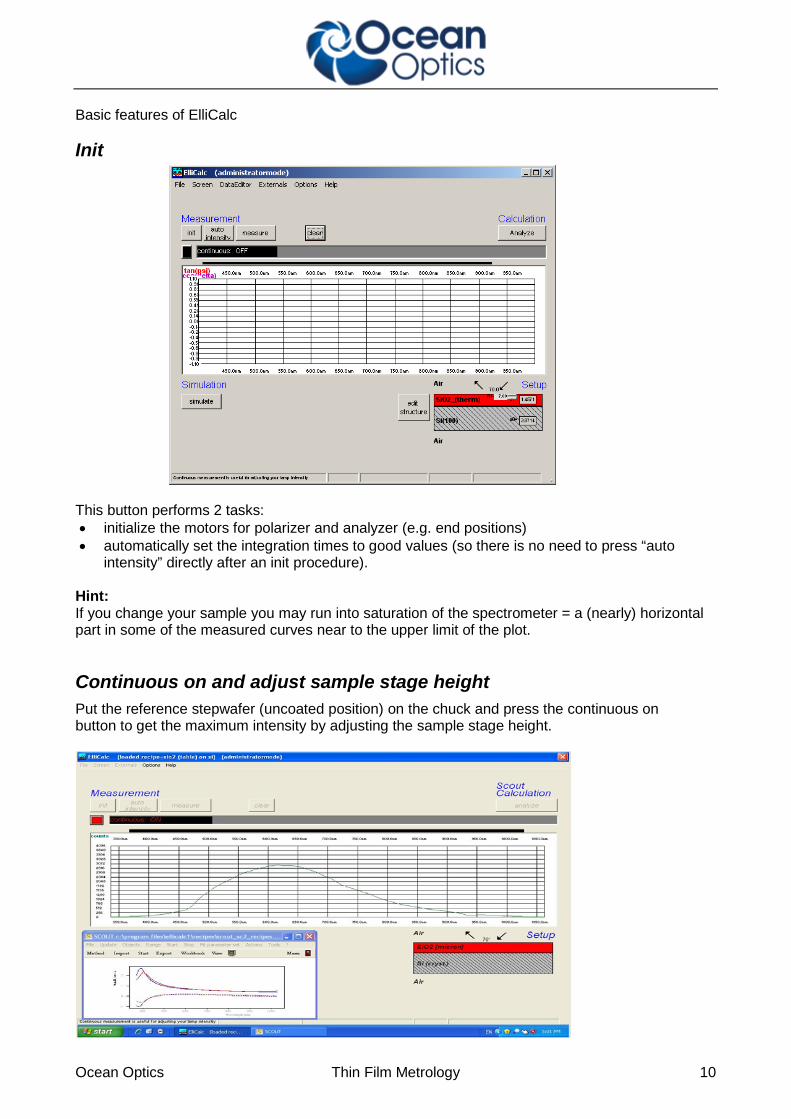
Init
This button performs 2 tasks: • initialize the motors for polarizer and analyzer (e.g. end positions) • automatically set the integration times to good values (so there is no need to press “auto
intensity” directly after an init procedure). Hint: If you change your sample you may run into saturation of the spectrometer = a (nearly) horizontal part in some of the measured curves near to the upper limit of the plot.
Continuous on and adjust sample stage height Put the reference stepwafer (uncoated position) on the chuck and press the continuous on button to get the maximum intensity by adjusting the sample stage height.

Ocean Optics Thin Film Metrology 11
Auto intensity This option automatically adjusts integration times. This button has to be pressed if you use a completely different sample (each sample has a different reflectivity, so a different integration time). Normaly the “init button” already has performed such an auto intensity procedure. If your sample is of the same type as your last sample (=has nearly the same reflectivity) it is not necessary to press this button. AutoIntensity tries to get 75% of the maximum allowed value.
Simulate This routine simulates a spectrum. • in SCOUT-mode: from the .sc2-layer recipe data within SCOUT • in ElliCalc internal mode: from the data in EditStructure (identical to the data in Thinfilm.ini-
file) Hint: If you want to have a short check which structure is simulated at the moment, put the mouse cursor over the appropriate layer for some seconds and you see the layer thickness. OR: Leave your mouse cursor for some seconds over the button SIMULATE and look at the text in the status bar.
Measure This routine measures the ellipsometric spectra of your test device. If you use a double spectrometer, you had to adjust the crossover wavelength. Below this wavelength the data are collected from channel A ("master spectrometer"), above this wavelength they are collected from channel B ("slave spectrometer").
Analyze This routine analyzes a spectrum (either simulated or measured) within the data extraction limits. • In SCOUT-mode: SCOUT is doing the
calculations. The structure that is simulated may only be changed within SCOUT.
• In ElliCalc’s internal mode: ElliCalc is doing the calculations (only thickness at the moment)

Ocean Optics Thin Film Metrology 12
Hint: To have a short check which structure is simulated at the moment, put the mouse cursor over the appropriate layer for some seconds and you see the layer thickness. OR: Leave your mouse cursor for some seconds over the button SIMULATE and look at the text in the status bar.
Continuous mode The continuous button switches between continuous mode (=red button) and “stop continuous” (button =black). Then there will be a continuous measurement of the signal (necessary to adjust the height and tilt of your stage !!) All others buttons of ElliCalc are disabled until you finish the continuous mode.
Fitness Any extraction of parameters is accompanied by a value of "fitness". This is the sum of the mean square deviations between measured and simulated curve (normalized to the range of extraction). The fitness is a rough guide whether your thickness value is "good" or not. In the file “Thinfilm.ini” you will find 3 entries in section [fit]: Failure_RedLevel=1 Failure_YellowLevel=0.1 RYG_LevelsAreDisplayed=False If you change the variable RYG_LevelsAreDisplayed from “False” to “True” (in main menu “Fitparameters”), the usual rainbow pattern on the screen will disappear and a simple color will show up. • If the fitness is below Failure_YellowLevel=0.1 you will see a GREEN color. • If the fitness is between Failure_YellowLevel=0.1 and Failure_RedLevel=1 you will see a
YELLOW color. • If the fitness is above Failure_RedLevel=0.1 you will see a RED color
Attention: If you measure very thick layers (with a good correlation between maxima positions, but bad correlation between signal heights) you may end up with high values of fitness, but nevertheless the thickness results may be o.k. For detailed measurement information, see in the ElliCalc manual!

Ocean Optics Thin Film Metrology 13
Lamp Replacement Replacement of UV-VIS module SPECEL-2000-BM-UV General information: Lifetime is approx. 1000h The warm-up time is within seconds for measurement ≥ 50nm (500Ǻ). For high performance and ≤ 50nm (500 Ǻ) wait approx. 10 min for lamp stabilization) To save lifetime you can switch on and off the light source by using Light source switch for every Measurement campaign. Replacement Please refer to SPECEL-2000-UV-VIS-NIR Replacement light source module document for detailed instructions. Order Information: SPECEL-2000-BM-UV lightsource module for replacement Replacement of the bulb at the supplier or factory side: Service - Repair

Ocean Optics Thin Film Metrology 14
Trouble Shooting
No Correct Measurement Go to configuration and run the Automatic mode for adapt Integration time and do measuring again. − Check recipe − Check the correct sample stage height , see chapter 0 Continuous on and adjust sample stage
height and try it again Light source may be weak, replace light source , see chapter 0
Ocean Optics Thin Film Metrology 15
− Lamp Replacement − If there has been a mains power interruption, restart you PC, switch off and on the SpecEl-
2000-(UV-)VIS-NIR system
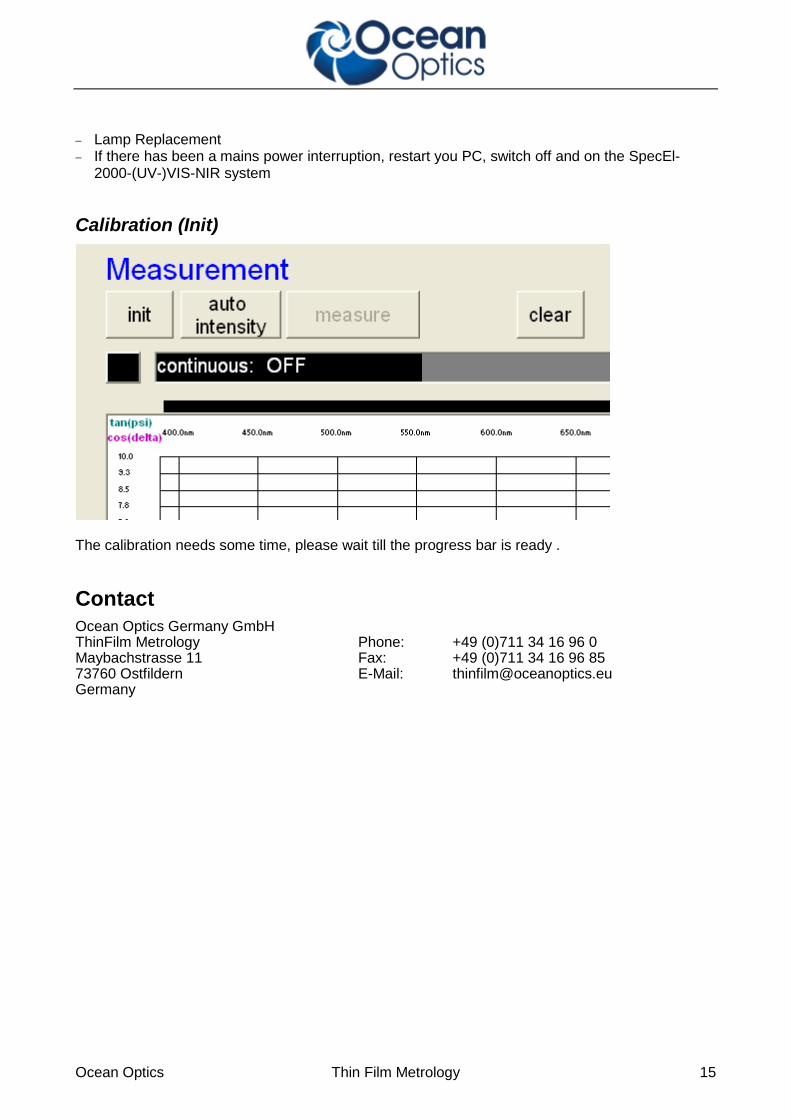
Calibration (Init)
The calibration needs some time, please wait till the progress bar is ready .
Contact Ocean Optics Germany GmbH ThinFilm Metrology Phone: +49 (0)711 34 16 96 0 Maybachstrasse 11 Fax: +49 (0)711 34 16 96 85 73760 Ostfildern E-Mail: [email protected] Germany

Ocean Optics Thin Film Metrology 16
Warranty Ocean Optics Germany GmbH warrants to the Original User of this instrument that it shall be free of any defects resulting from faulty manufacture of this instrument for a period of 12 months from the original data of shipment. There are no warranties for the Halogen Bulb(-Module). This instrument should not be used for any Clinical or Diagnostic Purposes. Data generated is not warranted in any way by Ocean Optics Germany GmbH. Any defects covered by this Warranty shall be corrected either by repair or by replacement, as determined by Ocean Optics Germany GmbH. There are no warranties which extend beyond the description herein. This Warranty is in lieu of, and excludes any and all other warranties or representation, expressed, implied, or statutory, including merchantability and fitness, as well as any and all other obligations or liabilities of Ocean Optics Germany GmbH, including, but not limited to special or consequential damages. No person, firm, or corporation is authorized to assume for Ocean Optics Germany GmbH. Any additional obligation or liability not expressed provided for herein except in writing duly executed by an officer of Ocean Optics Germany GmbH. Warranty Handling Clear with your local distributor the problem or fault. In case of warranty your local distributor will give you a RMA number. Send your instrument free of charge and insured to your local distributor. Please take care of secure and proper packaging. Use a wooden box on a wooden pallet! Your distributor will inform you on delivery time. If there is repair out of warranty you will be informed about repair cost. The system will be on hold till you have officially ordered the repair. The system will be send back to you free of transport cost and insured (in case of warranty)