specia conditions, tech spec & preamble for ash pond
DESCRIPTION
nalco specificationsTRANSCRIPT

Tender for Expansion of Ash Pond at NALCO’s Alumina Refinery at Damanjodi
TENDER NO: NBC/P&T/11/040/1704
TENDER DOCUMENT
FOR EXPANSION OF ASH POND
DAMANJODI
SPECIAL CONDITIONS OF CONTRACT, TECHNICAL SPECIFICATIONS &
PREAMBLE TO BILL OF QUANTITY
National Aluminium Co. Ltd, (A Govt of India Enterprise)
Bhubaneswar
Tender for Expansion of Ash Pond at NALCO’s Alumina Refinery at Damanjodi
TENDER NO: NBC/P&T/11/040/1704
TENDER
FOR
EXPANSION OF ASH POND AT NALCO’s ALUMINA
REFINERY AT DAMANJODI
SPECIAL CONDITIONS OF CONTRACT
Tender for Expansion of Ash Pond at NALCO’s Alumina Refinery at Damanjodi
TENDER NO: NBC/P&T/11/040/1704
CONTENTS
1. GENERAL 2. SCOPE OF WORK 3. GENERAL INFORMATION ON PLANT SITE AND CLIMATE DATA 4. CONSTRUCTION WATER SUPPLY AND POWER SUPPLY 5. EARNEST MONEY DEPOSIT 6. PRICE BASIS 7. SALES TAX CLEARANCE CERTIFICATE 8. INCOME TAX 9. TIME OF COMPLETION 10. SCHEDULE OF RATES 11. CONTRACTOR’S REMUNERATION 12. CONTRACTOR’S REMUNERATION 13. PROJECT SCHEDULING & MONITORING 14. LABOUR LAWS ETC 15. LABOUR LICENSE 16. CONSTRUCTION 17. FIELD LABORATORY 18. MEASUREMENT OF WORKS 19. TERMS OF PAYMENT 20. CONSTRUCTION METHODOLOGY/REQUIREMENTS 21. ENTRY PASSES, GATE PASSES, WORK PERMITS 22. SAFETY REGULATIONS 23. SITE CLEANING 24. LOCAL ROADS & HAUL ROADS

Tender for Expansion of Ash Pond at NALCO’s Alumina Refinery at Damanjodi
TENDER NO: NBC/P&T/11/040/1704
25. SURVEY AND LEVEL/SETTING OUT OF WORK 26. DRAWINGS AND DOCUMENTS 27. CONDITIONS FOR ISSUE OF CEMENT AND STEEL 28. BG / INDEMNITY BOND FOR FREE ISSUE MATERIAL 29. SCOPE OF SUPPLY BY THE CONTRACTOR 30. ADDITIONAL WORKS/EXTRA WORKS 31. INSPECTION OF SUPPLY ITEMS 32. TESTS AND INSPECTION 33. FINAL INSPECTION 34. RESPONSIBILITY OF CONTRACTOR 35. MEASUREMENT OF WORK 36. EXCAVATION BY BLASTING 37. VARIATION IN CONTRACT VALUE 38. COMPUTERISED CONTRACTOR’S BILLING SYSTEM 39. QUALITY ASSURANCE / QUALITY CONTROL PROGRAMME 40. EXISTING SERVICES 41. CONTRACTOR’S SITE ESTABLISHMENT 42. LABOUR COLONY/ TEMPORARY OFFICE ETC 43. COMPLETION DOCUMENTS 44. CONTRACT AGREEMENT 45. GENERAL ENVIRONMENT REQUIREMENT 46. STATUTORY APPROVAL FOR ELECTRICAL WORKS Annexure I
Tender for Expansion of Ash Pond at NALCO’s Alumina Refinery at Damanjodi
TENDER NO: NBC/P&T/11/040/1704
SPECIAL CONDITIONS OF CONTRACT 1.0 GENERAL 1.1 Special Conditions of Contract shall be read in conjunction with the General
Conditions of Contract, Schedule of Rates, Specification of work, Drawings and any other document forming part of this contract wherever the context so requires.
1.2 Notwithstanding the sub-divisions of the document into these separate sections
and volumes, every part of each shall be deemed to be supplementary to and complementary to every other part and shall be read with and into the contract so far as it may be practicable to do so.
1.3 Where any portion of the Special Conditions of Contract is repugnant to or at
variance with any provisions of the General Conditions of Contract, then unless a different intention appears, the provision of the Special Conditions of Contract shall be deemed to override the provision of the General Conditions of Contract only to the extent such repugnancies or variations in the Special Conditions of Contract as are not possible of being reconciled with the provision of General Conditions of Contract.
1.4 The materials, design and workmanship shall satisfy the applicable standards,
specifications contained herein and codes referred to. Where the Technical Specifications stipulate requirements in addition to those contained in the Standard Codes and Specifications, those additional requirements shall also be satisfied.
1.5 Wherever it is mentioned in the specifications that the Contract shall perform
certain work or provide certain facilities, it is understood that the Contractor shall do so at his own cost and the Contract Price shall be deemed to have included cost of such performances and provisions, so mentioned.
1.6 In case of contradiction between relevant Indian Standards, General Conditions of
Contract, Special Conditions of Contract, Specifications, Drawings, Schedule of Prices / Rates, the following shall prevail in order of precedence:
i) Fax of Intent, Detailed Letter of Intent/ Award along with Statement of
Agreed Variations (if any) and its enclosures. ii) Schedule of Prices / Rates. iii) Special Conditions of Contract. iv) Instructions to Bidders. v) Drawings. vi) Technical Specifications. vii) General Conditions of Contract. viii) Relevant Indian Standards / Specifications.
1.7 The Engineer may order the Contractor to suspend any work, which in the
opinion of the Engineer may be subjected to damage by the then prevailing weather conditions.
Tender for Expansion of Ash Pond at NALCO’s Alumina Refinery at Damanjodi
TENDER NO: NBC/P&T/11/040/1704
1.8 Unless specifically mentioned otherwise in the contract, the bidder shall quote
rates for the finished items and shall provide for the complete cost towards power, fuel, tools, tackles, equipment, construction plant, temporary work, labour materials, levies, taxes, transport, layout, repairs, rectification, maintenance till handing over, supervision, colonies, shops, establishments, services, temporary roads, revenue expenses, contingencies, overheads, profits and all incidental items not specifically mentioned but reasonably implied and necessary to complete the work according to the contract.
1.9 The decision of the Engineer-in-charge shall be final and binding on the
Contractor regarding clarification of items in the schedule with respect to other sections of the contract/specifications.
1.10 NALCO reserves the right to award the whole works to a single contractor or
split the work between more than one contractor. The rates should remain firm irrespective of the above.
1.11 The specification shall be read in conjunction with the description of item in the
schedule. The schedule of items shall have precedence over any contrary statement mentioned anywhere in the document.
2.0 SCOPE OF WORK 2.1 The scope of work envisaged in this contract shall include-:
(i) Raising of Ash Pond dam heights from the present stage of construction for the following three earth dams: Orissa 5: From crest elevation +920 M to EL930 M Orissa 4: From crest elevation +920 M to EL930 M Orissa 3: Tail berm level elevation +923 M to EL930 M
Downstream vertical raising method of construction shall be followed while raising the dam heights of O-5 and O-4.
2.2 The work broadly includes, but not limited to the following elements, to be
executed on item rate basis:
- Stripping of dam site. - Excavation in cut-off trenches.
- Back-filling of cut-off trench with compacted layers of impervious earth
including transportation of earth from borrow areas. - Formation of embankment section in semi-pervious/ impervious zones, in
compacted layers, including transportation of earth from borrow areas.
Tender for Expansion of Ash Pond at NALCO’s Alumina Refinery at Damanjodi
TENDER NO: NBC/P&T/11/040/1704
- Laying of filter materials for chimney drainage, base drainage and
horizontal filter layers, including supply of material. The scope also includes locating the existing Chimney filter in the body of old dyke and connecting the same to new chimney filter as specified.
- Providing rip-rap on the u/s slope of the dam, including supply of material. - Laying of filter materials or the u/s slope of the dam, including supply of
material. - Turfing on d/s slope of dam. - Providing surface drainage arrangement for d/s slope of dam.
- Closure of existing spillway.
- Dismantling of existing rock toe & stacking the same for reuse - Construction of rock toe including supply of material.
- Constructing of new spillway. - Grouting.
- Construction of garland drain.
- Construction of approach road on the berms of the dams and linking the
same with existing roads in different elevations.
- Renovation / construction of existing ash reclamation ramp civil works for raising from El- 920.0 M to 930.0 M
- Any other works felt necessary for the completion of the work but not
specifically covered above . 2.3 The technical specifications and drawings cover the dam and the pertinent work,
the construction of which shall be carried out in accordance thereof or as per agreed and accepted deviations thereto.
3.0 GENERAL INFORMATION ON PLANT SITE AND CLIMATE DATA 3.1 Location Nalco’s existing Alumina Plant is located at Damanjodi, in Koraput District, in
the state of Orissa at an Altitude of approx. 1000M from MSL. The plant is located about 12 Km from National Highway- 43 connecting Raipur to Vizianagaram and about 40 Km from the District HQ Koraput. The East Coast Railway line connecting Koaraput to Rayagada passes through Damanjodi. The Ash Pond is situated adjacent to the Township on South West side of Alumina
Tender for Expansion of Ash Pond at NALCO’s Alumina Refinery at Damanjodi
TENDER NO: NBC/P&T/11/040/1704
Plant. The nearest major Air port and Sea port is situated at Vishakhapatnam, which is about 190 Km from Damanjodi.
The Bidder has to acquaint himself with the access to the site, local working
environment, local interference, interruption of work (if any), that they may encounter during the pendency of contract, availability of local facilities such as railway connectivity, transport facilities, material, labour and the bidder shall quote the price taking into account all expenses likely to arise in this regard.
The intending tenderer shall be deemed to have visited the site and familiarised
themselves thoroughly with the site conditions before submitting their tenders. Non-familiarity with the site conditions will not be considered a reason either for extra claims or for not carrying out work in strict conformity with drawings and specifications.
3.2 Climatic Condition
The climatic conditions pertaining to the plant site is as indicated below:
Barometric pressure (Monthly avg) .. 915.1 mbar (Maxm)
.. 901.8 mbar (Minm)
Temperature:
Maximum dry bulb temperature .. 46.6 oC
Minimum dry bulb temperature .. 3 oC
Maximum wet bulb temperature .. 21.6 oC (avg)
Minimum wet bulb temperature .. 14.0 oC (avg)
Maximum relative humidity .. 89%
Minimum relative humidity .. 50 %
Rainfall
Heaviest rainfall in 24 hours .. 354 mm
Highest Annual Rainfall .. 2932 mm
Prevailing wind direction is .. West and North west predominantly from
Maximum wind speed .. 60 Km/ Hr
It is important to note that Damanjodi experiences continuous monsoon from
June to September.
3.3 Communication The nearest post office is at Damanjodi with the Postal address as follows:
M&R Complex, National Aluminium Company Limited Damanjodi, District: Koraput. Pin : 763 008 (Orissa)
Tender for Expansion of Ash Pond at NALCO’s Alumina Refinery at Damanjodi
TENDER NO: NBC/P&T/11/040/1704
Damanjodi is now well connected with facilities like Telephone, Fax, Internet, Cell phone etc. and can be contacted from anywhere across the globe.
3.4 Medical Facilities:
Hospital facilities are available on chargeable basis in Nalco’s township. Besides hospital facility is also available at HAL, Sunabeda and District HQ Hospital, Koraput. However tariff and other details may be obtained by the bidder.
4.0 CONSTRUCTION WATER SUPPLY AND POWER SUPPLY In partial modification of Clause 2.2 and 2.3 of General Conditions of Contract
(GCC), the Bidder should note the following: Construction Water shall be arranged by the Contractor at their own cost. The
Construction Water so arranged by the Contractor shall be tested periodically by authorised Govt./Private laboratory at their own cost. Periodicity shall be decided by the Owner for such water testing.
Construction power required for this work has to be arranged by the Bidder at
their own cost. The Bidder has to get their electrical installation certified by Central Electricity Authority (CEA), Chennai. However Power (if available) from Owner’s source may be made available as per applicable tariff subject to meeting all statutory clearances at Contractor’s cost.
5.0 EARNEST MONEY DEPOSIT The bank guarantee furnished towards Earnest Money Deposit as per relevant
Clause of General Conditions of Contract shall be kept valid for a period of 06 (six) months from the date of opening of tender.
6.0 PRICE BASIS 6.1 Works Contract The entire works as per Scope of Work covered under this contract shall be
treated as “Works Contract”. The quoted prices/ rates of the Bidders indicated in schedule of rates shall include incidence of Works Contract Tax / Turnover Tax.
6.2 Taxes and Duties In addition to the relevant clause in GCC, Bidders to note the following: All prices/rates quoted in schedule of rates shall be inclusive of all applicable
taxes and duties etc prevalent at the time of tender. If at a later date, due to any Govt. notification, any additional/ new tax/duty is imposed, then the same shall be to the Owner’s account and the same shall be reimbursed on actual basis on production of documentary evidence to be furnished by the Bidder. The base date for this purpose shall be the due date of submission of price bid/revised price bid, as the case may be. Any variation in the existing rates of taxes/ duties shall be absorbed by the Contractor.
Tender for Expansion of Ash Pond at NALCO’s Alumina Refinery at Damanjodi
TENDER NO: NBC/P&T/11/040/1704
The Bidder shall pay and bear all liabilities in respect of statutory variations regarding all taxes, duties, levies etc. that may be imposed beyond the contractual completion date in case the delay is due to reasons not attributable to Owner.
7.0 SALES TAX CLEARANCE CERTIFICATE Bidders must submit attested copy of registration/clearance certificate in
prescribed proforma under the Orissa Sales Tax Act. Alternatively, bidders must give an undertaking that they would comply with this statutory requirement after award of work. Owner shall deduct Sales Tax on Works Contract as per prevalent rates from each RA bill and remit the same with Sales tax authorities as statutory deductions.
8.0 INCOME TAX Income Tax at the prevailing rate as applicable from time-to-time shall be
deducted from Contractor’s bills as per Income Tax Act and Quoted Rates shall be deemed to include this.
9.0 TIME OF COMPLETION 9.1 Time is the essence of contract. The work shall be executed strictly as per the
Time Schedule given in Notice Inviting Tender (NIT). 9.2 All work within scope of this tender must be completed within a period of 18
(eighteen) months as stipulated in the NIT from the date of order/ Fax of Intent (FOI) and strictly in accordance with the construction programme to be drawn. Construction work at site must commence within three (3) weeks from the date of FOI. The date of order shall be reckoned from the date of issue of the Fax of Intent. Since the work is envisaged in the sensitive area of Ash Pond, the raising of all the dykes must be taken up simultaneously and completed before the onset of monsoon.
9.3 The bidder shall furnish his proposed time schedule along with his quotation. 9.4 The time schedule should be in the form of PERT network considering the date
of issue of Fax of intent as the zero date and should show completion of various events/activities there from.
9.5 The time schedule network shall clearly include all-important events/activities
regarding mobilisation of earth moving equipment, procurement of construction material, setting up site laboratory, construction schedule of each dyke etc. commensurate with the overall time schedule.
9.6 The effective date of contract/time of commencement shall be the date of issue of
Fax of Intent or Letter of Acceptance whichever is earlier. 10.0 SCHEDULE OF RATES 10.1 The Schedule of Rates shall be read in conjunction with Special Conditions of
Contract, General Conditions of Contract, Scope of Work, Scope of Supply, Technical Specification, Drawings and any other document forming a part of this Contract.
Tender for Expansion of Ash Pond at NALCO’s Alumina Refinery at Damanjodi
TENDER NO: NBC/P&T/11/040/1704
10.2 All expenses towards mobilisation at site and demobilisation including bringing
all required equipment, work force, materials, dismantling/ demobilisation of equipment, clearing of site, keeping the minimum staff & equipments in rainy seasons/ off seasons at site to meet the exigencies etc. shall be deemed to be included in the rates quoted and no separate payments on account of such expenses shall be entertained.
11.0 CONTRACTOR’S REMUNERATION The price to be paid by the Owner to the Contractor for the whole work done and
for the performance of all the obligation undertaken by the Contractor under the contract document shall be ascertained by the application of the respective schedule of rates (the inclusive nature of which is more particularly defined by way of application but not of limitation, with clause no. 11.4) and payment to be made accordingly to the work actually executed and approved by the Engineer-in-Charge. The sum so ascertained shall (exception only as and to the extent expressly provided here in) constitute the sole an inclusive of remuneration of the Contractor under the Contract and no further or other payment whatsoever shall be or become due or payable to the Contractor under the Contract.
12.0 SCHEDULE OF RATES TO BE INCLUSIVE The prices / rates quoted by the Contractor shall remain firm till the issue of final
certificate and shall not be subject to escalation. Schedule of rates shall be deemed to include and cover all costs, expenses and liabilities of every description and all risks of every kind including all type of local / villagers interference / obstruction / interruption / pollution problems of dried red mud/ash blowing in the air or any other problems which may likely to occur from time to time to be taken in executing, completion and handing over the work to the Owner by the contractor. The Contractor shall be deemed to have known the nature, scope, magnitude and the extent of the works and materials required though the contract document may not fully and precisely furnish them. Contractor shall make such provision in the schedule rates as he may consider necessary to cover the cost of such items of work and materials as may be reasonable and necessary to complete the work. The opinion of the Engineer-in-Charge as to the items of work which are necessary and reasonable for completion of work shall be final and binding on the contractor although the same may not be shown on or described specifically in contract documents.
Generally of this present provision shall not be deemed to cut down or limited in
any way because in certain cases it may and in other cases it may not be expressly stated that the contractor shall do or perform a work or supply articles or perform with services at his own cost or without addition of payment or without extra charge of works to the same effect or that it may be stated or not stated that the same are included in and covered by the Schedule of Rates.
12.1 Schedule of Rates to cover Constructional plant, Material, Labour etc. Without in any way limiting the provisions of other sub clauses the schedule of
rates shall be deemed to include and cover the cost of all constructional plant,
Tender for Expansion of Ash Pond at NALCO’s Alumina Refinery at Damanjodi
TENDER NO: NBC/P&T/11/040/1704
temporary works (except as provided for herein), pumps, materials, labour, insurance, fuel, stores, and appliances to be supplied by the contractor and all other matters in connection with each item in the schedule of quantities and the execution of the work or any portion thereof finished complete in every respect and maintained as shown or described in the contract document or as may be ordered in writing during the continuance of the contract.
12.2 Schedule of Rates to cover Royalties, Rents and Claims The schedule of rates shall be deemed to include and cover the cost of all
royalties and fees for the article, processes, protected by letters, patent or otherwise incorporated in or used in connection with the works, also all royalties, rents and other payments in connection with obtaining materials of whatsoever kind for the works and shall include and indemnity to the owner which the contractor hereby gives against all actions, proceedings, claims, damages, costs and expenses arising from the incorporation in or use on the works of any such articles, process or charges if levied on materials, equipment or machinery to be brought to site for use on work, shall be borne by the contractor.
12.3 Schedule of Rates to cover taxes and duties No exemption of reduction of custom duties, excise duties, sales, tax, quay or any
port duties, transport charges, stamp duties or Central or State Government or Local Body (or from any other body) or Municipal Taxes and duties, taxes or charges whatsoever will be granted or obtained and all expenses of which shall be deemed to be included in and covered by the schedule of rates. The contractor shall also obtain and pay for all permits or other privileges necessary to complete the work.
12.4 Schedule of Rates to cover Risk of Delay
The schedule of rates shall be deemed to include and cover the risks of all possibilities of delay and interference with the contractors conduct of work which occur from any cause including orders of owner in the exercise of his powers and on account of extension of time granted due to various reasons and for all other possible causes of delay.
12.5 Schedule of Rates can not be altered
For work under unit rate basis no alteration will be allowed in the schedule of rates by reasons of works or any part of them being modified, altered, extended, diminished or omitted. The schedule of rates is of fully inclusive rates which have been fixed by the contractor and agreed to by the Owner and cannot be altered.
12.6 The schedule of rates to cover for working in operating pond. Contractor’s rates
shall be deemed to include taking into account that he has to work in operating pond and shall take sufficient care in moving the plants, equipment and materials from one place to another, so that they do not cause any damage to any person or to the property of the owner or to third party including over head and underground cables/pipe lines. In the event of such damages including consequential loss of production and operation of the plant or services in any plant/ establishment as
Tender for Expansion of Ash Pond at NALCO’s Alumina Refinery at Damanjodi
TENDER NO: NBC/P&T/11/040/1704
estimated by the owner or ascertained or by the third party shall be borne by the contractor.
12.7 Since the work is to be executed for the expansion of the ash pond, the rate of the
contractor shall also deem to include all interference/ obstruction/ interruption for which no compensation shall be paid to the Contractor.
12.8 Rate shall be quoted both in figure and in words in clear legible writing. No over
writing is allowed. All scoring and cancellation should counter signed by the tenderer. In case of illegibility, the interpretation of the engineer-in-charge shall be final.
12.9 Rate quoted shall remain firm during the entire contract period and no claim
whatsoever towards escalation shall be entertained. 13.0 PROJECT SCHEDULING & MONITORING The successful tenderer shall submit a Master Network within three weeks from
date of issue of Fax of Intent. 13.1 The master network will be in the form of PERT/CPM NETWORK prepared
system wise containing major milestones in all phases of execution of contract. Each event/activity will also have earliest completion date, latest completion date and float in number of days/weeks.
13.2 The final master network as mutually agreed upon will form the basic document
from which schedules for design, engineering, procurement, construction and commissioning will be arrived at. These schedules will be prepared discipline or system wise.
13.3 The final master network shall also form the basis for review of schedules, short-
term programme and progress reporting for the entire run of the contract. The frequency/periodicity of programming and reporting will be mutually agreed upon.
13.4 Progress reporting shall be done by the Contractor on mutually agreed formats.
Reports on such formats will be sent regularly to the Engineer-in-Charge in reproducible with six copies of print as per frequency/periodicity agreed upon from time to time.
14.0 LABOUR LAWS etc. 14.1 The Contractor shall have independent account codes from concerned Regional
Provident Fund Commissioner for Provident Fund and Independent account code from Regional Director ESIC for ESI. Fulfilling all statutory stipulations towards PF & ESI is mandatory for the bidders.
14.2 It is to be noted that the subject contract would be awarded only to those agencies
who have fulfilled the following requirements:
a) P.F. Registration Number allotted to them by RPFC.
Tender for Expansion of Ash Pond at NALCO’s Alumina Refinery at Damanjodi
TENDER NO: NBC/P&T/11/040/1704
b) The agencies should promptly deposit P.F. deduction of the eligible contract employees plus the employer’s contribution to the RPFC. For this purpose agency must submit a certificate in their Bill that PF amount has been deducted from the eligible employees and along with the employer’s contribution has been deposited with R.P.F.C. For this purpose agency must submit a certificate in their Bill that PF amount has been deducted from the eligible employees and along with the employer’s contribution has been deposited with R.P.F.C. In support of this the agency must furnish the challan/ receipt for the payment made to RPFC for the earlier months.
14.3 If the certificate and the challan/ receipt referred to in clause 14.2(c) above are
not furnished, the Finance & Accounts Dept. of NALCO will deduct 16% (Sixteen percent) of the amount of the Contractor’s bill and retained deposits may only be refunded to the Contractor on production of the challan/ receipt.
15.0 LABOUR LICENSE Before starting of work, the Contractor shall obtain a license from the concerned
authorities under the Contract Labour (Abolition and Regulation) Act 1970, and furnish copy of the same to the Owner.
16.0 CONSTRUCTION: Bidder to note that the existing ash pond will be handed over
to them for raising the dyke/construction as is where is condition. 16.1 Contractor shall observe all Codes specified in respective specification, all national
and local laws, ordinances, rules and regulations and requirements pertaining to the work and shall be responsible to fulfill all such norms.
16.2 Contractor shall have at all times during performance of the work, post a
technically competent person to supervise the work at the work premises. Any instruction given to such a person by the Owner/ Engineer in charge shall be construed as having been given to the Contractor.
16.3 Owner reserves the right to inspect all phases of Contractor’s operations to ensure
conformity to the specifications. Owner will have engineers, inspectors or other duly authorised representatives, made known to the Contractor, present during progress of the work and such representatives shall have free access to the work at all times. The presence or absence of an Owner’s representative does not relieve the Contractor of the responsibility for quality control in all phases of the work. In the event that any of the work being done by the Contractor is found by Owner’s representatives to be unsatisfactory or not in accordance with the drawings, procedures and specifications, the Contractor shall, upon verbal notice of such discrepancy or deficiency, take immediate steps to revise the work in a manner to conform to the relevant drawings, procedures and specifications.
16.4 The Contractor shall carry out required supervision and inspection as per Quality
Assurance Plan and furnish all assistance required by the OWNER in carrying out inspection work during this phase. The owner will have engineers, inspectors or other authorised representatives present who are to have free access to the work at all time. If an Owner’s representative notifies the Contractor’s authorised
Tender for Expansion of Ash Pond at NALCO’s Alumina Refinery at Damanjodi
TENDER NO: NBC/P&T/11/040/1704
representative of any deficiency, or recommends action regarding compliance with the specifications, the Contractor shall make every effort to carry out such instructions to complete the work conforming to the specifications and approved drawings in the fullest degree consistent with best industry practice.
16.5 During the pendency of contract (during the construction) the Owner will continue
with Pond filling and the pond may be subjected to settlement, seepage, leakage etc. In such cases any repair/ reconstruction required for the safety of the dyke/pond shall be carried out by the Contractor at their cost.
17.0 FIELD LABORATORY
The Contractor shall set up a Field Laboratory at his own cost for carrying out the various tests as enumerated/mentioned in the Technical Specifications and the Technical documents that will be furnished to them during the performance of the work. Alternatively the contractor shall make his own arrangement at his own cost for carrying out the above test in the nearest approved laboratories in the presence of authorized representative of the Owner. In such case care should be taken that the dependence on outside laboratories does not affect the progress/expeditious execution of work.
17.1 All the tests either at the field or at outside laboratories concerning the execution of
the work and supply of material is by the contractor shall be carried out by the contractor at his own cost.
17.2 A list of the suggested Laboratory equipments required for the field laboratory is enclosed in Annexure –III to this SCC. How ever if any more equipments is required to meet the field soil tests, the same shall be arranged immediately as per the direction of Engineer-in-Charge..
18.0 MEASUREMENT OF WORKS
For all payment purposes, measurement will be based on the execution drawings. Wherever details are inadequate or not available in the execution drawings, physical measurements will be taken by the contractor in the presence of the representative of the Engineer-in-Charge. In such cases, payment will be made on actual measurements. Measurement will be made in units indicated in Schedule of Rates. Linear Measurements will be in metre corrected to nearest centimeter.
19.0 TERMS OF PAYMENT
Payment will be made through monthly running account bills based on joint measurements with Engineer-in-Charge against the work done during the preceding month on the basis of item rates as accepted in the contract in following manner:
a) All Items of work except Turfing & earth filling in embankment:- - 95% on completion of work on prorata basis as certified in
Monthly progress bill / R.A.Bills. - 5% on completion of all works and final acceptance thereof.
Tender for Expansion of Ash Pond at NALCO’s Alumina Refinery at Damanjodi
TENDER NO: NBC/P&T/11/040/1704
b) Earth filling in embankments items:- - Running measurements for embankment filling material of soil
will be paid at 90% of the tendered rate up to 50% of the quantities given in the schedule of quantities & rates.
- The quantities in excess of 50% will be paid at 95% of the tendered rates.
(c) Payment for final bill shall be made at full tendered rate. For the actual
quantities executed and after fulfilling all the contractual obligations as required by the contractor. Rates shall be inclusive of providing all construction material and construction of all haul roads (other than those maintained by NALCO) and ramps, lighting of work area and embankment and laying materials including all leads and lifts etc.,
c) Turfing items:
- 70 % on completion of work on prorata basis as certified in Monthly progress bill/ R.A.Bills.
- 30 % after maintaining for one year after completion of the total
work on final acceptance thereof.
20.0 CONSTRUCTION METHODOLOGY/REQUIREMENTS 20.1 The contractor shall be entirely responsible for execution of the work covered
under this tender in a workmanlike and expeditious manner, as per the technical specifications, drawings attached to this tender document and as per instructions of Engineer-in-Charge.
20.2 The work shall be executed strictly in accordance with the Technical
specifications attached to this Tender document. NO variation to the same is acceptable.
20.3 Construction Equipments: The Contractor shall without prejudice to his overall responsibility to execute and
complete the work as per specifications and time schedule, progressively deploy adequate number of suitable equipments, such as required capacity excavator, vibratory sheep foot Roller, Bulldozer/Grader/Water tanker, Tipper and other suitable equipment required for due completion of work, tools and tackles and augment the same as decided by the Engineer-in-Charge depending on the exigencies of the work so as to suit the construction schedule and complete the works within the contractual completion period without any additional cost of Owner. No Construction Equipment shall be supplied by the Owner. A list of the suggested equipments required for the above works is enclosed in Annexure-“II”. The party has to mobilise the same for the work and also maintain a minimum equipments in the rainy season/ off season in running condition & with operators to meet the exigencies.
Tender for Expansion of Ash Pond at NALCO’s Alumina Refinery at Damanjodi
TENDER NO: NBC/P&T/11/040/1704
20.4 Site Organisation: The Contractor shall without prejudice to his overall responsibility to execute and
complete the works as per specifications and time schedule progressively deploy adequate qualified and experienced personnel together with skilled/unskilled manpower and augment the same as decided by Engineer-in-Charge depending on the exigencies of work to suit the construction schedule without any additional cost to Owner.
21.0 ENTRY PASSES, GATE PASSES, WORK PERMITS:
21.1 The works under this contract are to be carried out in areas declared as plant limits, adjacent / adjoining to the existing operating plant. As such, Contractor is required to abide by all safety and security regulations of the Owner enforced from time to time.
21.2 Entry Passes 21.2.1 The Contractor has to apply for photo entry passes for his workers & staff in a
prescribed proforma available with Owner for persons requiring entry in to Plant premises as required.
21.2.2 Unutilised/ Expired entry passes shall have to be returned immediately to Owner.
21.2.3 In case of loss of any entry pass, the Contractor has to lodge FIR with local police station and inform the Engineer-in-Charge and will have to pay Rs.150/- against each entry pass. The Contractor is required to keep track of all entry passes issued and returned.
21.2.4 Identity card issued by the Security Section should always be carried/ displayed by the Contractor’s employee or person while working inside the Plant.
21.3 Gate Passes: To bring materials/ equipment/ tools/ tackles etc., to Construction site the work,
the Contractor has to produce challan/ proper documents to the Owner’s personnel at gate. The materials shall be checked thoroughly by the Owner’s personnel at Gate and recorded in their register before allowing any materials to the site. It is Contractor’s responsibility to see that the recorded entry No., date, signature of Owner’s authorised representative with stamp are there on the challan/ supporting documents before taking any materials into work site. In addition to above, entry of the material will be permitted only during the stipulated working hour, and more so, if consignee is available to receive the said material.
21.4 To take Contractor’s materials out of the site, the Contractor has to apply with specific purpose/ reasons to the Engineer-in-Charge, attaching challan/ supporting documents signed by Company’s personnel at gate during entry.
21.5 Vehicle Permit Permits are to be obtained separately for use of vehicles/ trailers etc. at work site. The following requirements are to be met to obtain vehicle permit:
Tender for Expansion of Ash Pond at NALCO’s Alumina Refinery at Damanjodi
TENDER NO: NBC/P&T/11/040/1704
i) Vehicle / Equipment etc., should be brought to site in good condition. ii) Valid Road tax certificate, fitness certificate and insurance policy from
competent authority. iii) Valid operating/driving license of drive / operator.
21.6 Validity of the Permit i) No permit is valid, if it is not renewed by authorised personnel. ii) The permit shall be issued for a maximum period of one month and if
extension is required, the Contractor has to apply for fresh permit.
iii) No permit is valid on holidays unless special permission is obtained from the competent authority.
22.0 SAFETY REGULATIONS
22.1 Regarding Work Permit: The work shall be carried out inside the plant as per safety practices enforced by
NALCO safety section and instructions of Engineer-in-charge issued from time to time. Many times it may happen that the working hours shall be drastically reduced or increased to meet certain safety requirements and the Contractor shall meet these requirements without any argument for time and financial implications. To obtain work permit and to satisfy all conditions laid down therein, shall be the responsibility of the Contractor. No claim for idling of machinery, plant, manpower etc., for safety reasons or non-issuance of work permit by In-charge, Safety Section shall be considered.
22.2 The Contractor shall abide by all safety regulations of the plant and ensure that safety equipment or specific job kit as stipulated in the Factory Act / Safety Hand Book is issued to the employee during the execution of work, failing which all the works at site will be suspended.
22.3 Regarding use of Vehicle i) Vehicle must not ply on any road within the Township at a speed exceeding
20 km/ hr.
ii) Mobile crane / loaded trucks / trailers must not exceed speed limit of 15 km/ hr inside the plant.
iii) No crane is allowed to move inside the plant with load.
23.0 SITE CLEANING 23.1 NALCO being a ISO 14000 Company, the Contractor shall comply with all the
provisions of ISO 14000 (EMS Criteria) for proper disposal of debris, unused oils, lubricants etc. in consultation with Engineer-in-Charge. The contractor shall also abide by other stipulations of ISO 14000 as laid down by the said system.
Tender for Expansion of Ash Pond at NALCO’s Alumina Refinery at Damanjodi
TENDER NO: NBC/P&T/11/040/1704
23.2 The Contractor shall take care of cleaning the working site from time to time for easy access to work site and also from safety point of view.
23.3 The Contractor shall from time to time clear and remove all rubbish and
constructions, equipment, unused materials, etc. resulting in the execution of the work. The disposal of rubbish will have to be done only in the areas earmarked by the Owner as per the direction of the Engineer-in-Charge. All streets and driveways in the work area shall be kept clear and unobstructed at all times.
23.4 Working site should be always kept cleaned up to the entire satisfaction of
Engineer-in-Charge. Before handing over of any work to Owner, the Contractor in addition to other formalities to be observed as detailed in the document shall clear the site to the entire satisfaction of Engineer-in-Charge.
24.0 LOCAL ROADS & HAUL ROADS Contractor shall make all temporary roads/approaches necessary for his work at
site at his own cost. Contractor shall also maintain already established roads/approaches, which are used by him.
24.1 The Owner has constructed link road connecting the work site to nearest highway
through its Township. The contractor shall plan transportation of construction materials, Earth moving equipment to work site in such a way that road accident are avoided and no damage is done to the existing roads.
24.2 The contractor shall construct and maintain at his own cost all suitable temporary
haul roads at the work site as may be found necessary by him for the execution of works. The location of all such haul roads and any subsequent modifications there to shall be got approved by the engineer-in-charge.
24.3 Separate payment will not be made for the construction and maintenance of the
temporary haul rods including any necessary special protection or strengthening required and all cost of such works shall be deemed to have been included in the cost of the item.
24.4 In case the party using our existing approach road for transporting the materials /
earth from borrow areas to Dams . The party will make regular repair & maintenance to keep the road serviceable at it’s own cost, fail to do so the owner will deduct the charges of the maintenance of the said road from the R.A.Bill or execute the repair at the party’s risk & cost.
25.0 SURVEY AND LEVEL/ SETTING OUT OF WORK 25.1 The Engineer-in-Charge shall furnish the relevant existing grid point with
benchmark on the land. It shall be Contractor’s responsibility to set out the necessary control points in and to set out the alignment of the various works. The Contractor shall have in his employ efficient survey team for this purpose and accuracy of such setting out works shall be Contractor’s responsibility.
25.2 The various works shall be done true to line, level and grade. The periodical
checking of these by NALCO staff not absolve the Contractor of his
Tender for Expansion of Ash Pond at NALCO’s Alumina Refinery at Damanjodi
TENDER NO: NBC/P&T/11/040/1704
responsibility regarding their accuracy. In case of any deviation in the discrepancy in line, level or grade at the meeting face or elsewhere, the Contractor shall make good involved, if any. Wherever such a discrepancy is found to arise at the junction of works of different Contractor, the relative liability to set right their respective discrepancy shall be fixed by the Engineer-in-Charge whose decision shall be final and binding on the Contractors concerned. The Engineer-in-Charge, shall further have unquestioned right, if need be, to rectify the discrepancies and recover the costs from the Contractor in the proportion as he may consider reasonable.
25.3 The Contractor shall give the Engineer-in-Charge not less than 24 (twenty four)
hours notice in writing of his intention to set out or give levels for any part of the work so that arrangements may be made for checking the same.
25.4 Work shall be suspended for such time as necessary for checking lines and levels
on any part of the works. 25.5 The Contractor shall at his own expense provide all assistance, which the
Engineer-in-Charge require, for checking the setting out of works. 26.0 DRAWINGS AND DOCUMENTS 26.1 The drawings accompanying the Tender Document are of indicative nature and
issued for tendering purpose only. Purpose of these drawings is to enable the Bidder to make an offer in line with requirements of the Owner.
26.2 These are preliminary drawings for tender purpose only and are by no means the
final drawings or show the full range of the work under the scope. Work has to be carried out on the basis of the drawings marked, “Released for Construction” with additions, alterations and modifications made from time to time and also according to any other that would be supplied to the contractor progressively during execution of the work.
26.3 Construction shall be as per drawings/specifications issued/approved by
Engineer-in-Charge issued from time to time during the course of execution of work. The quoted rates shall be deemed to include cost of preparation and submission of fabrication drawings (if any) for review and approval of Engineer-in-Charge. It is however, clearly agreed by the Contractor that review and approval of the drawings by Engineer-in-Charge shall not absolve the Contractor of his responsibility to carry out the work as per specifications.
26.4 However, no extra claim whatsoever, shall be entertained for variation in the
“Approved for Construction” and “Tender Drawings” regarding any changes/ units. Construction shall be as per drawings/ specifications issued/ approved by Engineer-in-Charge during the course of execution of work. The quoted rates shall be deemed to include cost of preparation and submission of fabrication drawings as specified elsewhere in the Tender Document for review and approval of Engineer-in-Charge. It is however, clearly agreed by the Contractor that review and approval of the drawings by Engineer-in-charge shall not absolve the Contractor of his responsibility to carry out the work as per specifications.
Tender for Expansion of Ash Pond at NALCO’s Alumina Refinery at Damanjodi
TENDER NO: NBC/P&T/11/040/1704
26.5 Contractor shall submit everyday a report on category wise layout and equipment
deployed along with the progress of work done on previous day in the performa prescribed by the Engineer-in-Charge.
27.0 CONDITIONS FOR ISSUE OF CEMENT AND STEEL 27.1 Owner will issue as per terms and conditions set forth in the General Conditions
of Contract, Cement & Steel as Free Issue materials from Owner’s stores or other issue points of Owner. Such issue would be only for permanent works.
Necessary indents shall be raised by the Contractor as per procedure laid down by Engineer-in-Charge from time-to-time when he requires the above materials for incorporating in the permanent works.
27.2 Steel & Cement: Owner will supply free issue materials like cement (in non-returnable bags) and
steel that will be required for all items involving use of cement and steel and the same will be made available at Owner’s stores or other issue points by Owner within the premises of their Project. All other materials will be supplied by the Contractor at his own cost. Necessary indents will have to be raised by the Contractor as per procedure laid down by Engineer-in-Charge from time to time for supply of free issue materials by Owner. The Contractor shall keep the Owner informed regarding his requirement of material to be supplied by Owner at least thirty (30) days in advance of his requirement of any such material.
If in case the Owner is not in a position to supply a small portion of the materials, the same have to be arranged by the Contractor by procuring from the open market subject to prior approval of the Owner regarding the quality and price. The procurement price will however be payable to the Contractor by the Owner at actual.
Such issue shall be subject to the following conditions :
i) Materials will be issued only for permanent works and not for making templates, other temporary works, enabling works etc. Any materials used for Temporary Works etc. shall not be taken into account for purpose of materials reconciliation.
ii) The Contractor shall bear all other costs including lifting, carting from issue points to work site/Contractor’s store, custody and handling etc. and return of surplus/serviceable/ scrap materials to Owner’s storage points to be designated by the Owner and no separate payment for such expenditure will be made.
iii) All steel shall be issued at standard lengths and no claim for extra payment on account of issue of non-standard lengths will be entertained. However for payment purposes, reinforcing steel will be measured in length and converted into weights by multiplying with respective unit weights as per Indian Standards. Cement, as received from the manufacture/stockiest will
Tender for Expansion of Ash Pond at NALCO’s Alumina Refinery at Damanjodi
TENDER NO: NBC/P&T/11/040/1704
be issued to the Contractor. The theoretical weight of each bag of cement for issue purposes will be considered as 50 kg. or 20 bags per MT.
The steel material will be issued on weighment basis. No tolerance will be given for rolling margin. The quoted rates shall include all the above wastage / cutting allowances / scrap etc.
The Contractor will have to submit their design mix for concrete keeping in view the requirements stipulated in Technical Specifications and IS:456, specifically regarding slumps and water cement ratio, and specific gravity of materials brought to site as analysed in the laboratories. The actual consumption of cement will be computed based on the design mix of concrete and certified quantities as per bills.
The theoretical consumption of cement shall be binding upon the Contractor for reconciliation of cement issued free of cost by the Owner. For any excess/under consumption based on these coefficients, the Contractor shall be suitably penalised, though, however, a variation +3% shall be considered, while effecting penal recovery. For other than concrete item the coefficients for consumption of cement shall be adopted as per CPWD practice. The above variation mentioned shall be applicable for these items also. No other allowances whatsoever shall be taken for reconciliation purposes.
The theoretical consumption of steel and cement required for the work will be calculated on the basis of approved drawing/joint measurement.
27.3 Scrap and Serviceable Material: For the purpose of accounting of reinforcing steel and structural steel other than
MS plates issued by the Owner, all cut pieces measuring in length of 2.0M and above when returned to Owner’s storage points, shall be treated as serviceable material and will be given full credit by the Owner. All pieces measuring less than 2.0M will be treated as wastage/scrap. For the purposes of accounting of MS plates, all plates measuring less than 1 M2 in area and having any dimension less than 200 mm shall be treated as wastage/scrap. For plates measuring more than 1 M2 in area and not having any dimension less than 200 mm when returned to Owner’s storage point, full credit will be given.
Excess cement in sealed bags when returned to Owner’s storage/issue points in good condition as certified by Engineer-in-Charge, will be given full credit.
On completion of the work, all serviceable material (steel & cement) shall be separately delivered and stacked as directed by the Owner.
Shortage in return of surplus materials issued by the Owner at free of cost to the Contractor, if any, shall be charged to the Contractor at a penalising rate of 1.5 (one and half) times of the market rates prevailing at the time of completion of work or termination of contract, as the case may be. In case of a dispute, the decision of the Engineer in this regard shall be final and binding.
Tender for Expansion of Ash Pond at NALCO’s Alumina Refinery at Damanjodi
TENDER NO: NBC/P&T/11/040/1704
27.4 Storage of Material: The materials to be supplied by the Owner to the Contractor for execution of this
contract shall always remain the absolute property of the Owner throughout the tenure of the Contract and at all times shall remain open for inspection by the Owner and the Engineer. The materials shall not be used by the Contractor for any purpose other than the scope of work specified under this contract. This material shall also not to be removed from the site by the Contractor due to any reason whatsoever. It will be responsibility of the Contractor to keep these materials in safe custody during execution of the contract against any theft, loss, pilferage, weather condition etc. The Contractor shall submit every month, the reconciliation statement indicating the opening stock of materials supplied by the Owner, materials utilised by the Contractor in execution of the Contract and closing stock. The Contractor shall make proper and adequate storage arrangements for storing of the material.
28.0 BG / Indemnity Bond for Free Issue Material The Bidder has to submit BG for 100% of the value of the material to be taken
outside the plant premises at any point of time, which is required for the work. Bidder to note that Ash pond area shall be considered as out side the plant premises. Considering the value of material likely to be taken out at any point of time, a floating BG of Rs.2,00,000/- has to be furnished by the bidder at the beginning of work prior to receiving any Free issue material from the Owner, which shall remain valid till expiry of the contract and settlement of material accounting for Free issue materials.
29.0 SCOPE OF SUPPLY BY THE CONTRACTOR 29.1 Scope of supply shall be as detailed in Specification of this Tender Document. 29.2 However, the procurement and supply of all other materials (except those covered
in Owner’s scope of supply), consumables etc. including necessary tools & tackles required for the completion of work shall be the responsibility of Contractor and the quoted price shall be deemed to include cost towards the same.
All materials, consumables, testing appliances, tools and tackles necessary for
completing the work except those specified in Clause. 27 above should be procured and supplied by the Contractor at his own cost.
The Owner will identify the borrow areas for earth etc. from Owner’s land. 29.3 Debris generated by the Contractor shall be disposed of by the Contractor at his
own cost in the areas earmarked by the Owner as per the direction of the Engineer-in-Charge.
30.0 ADDITIONAL WORKS/EXTRA WORKS OWNER / ENGINEER IN CHARGE reserves their right to execute any
additional works/ extra works, during the execution of work, either by themselves or by appointing any other agency, even though such works are incidental to and necessary for the completion of works awarded to the Contractor. In the event of
Tender for Expansion of Ash Pond at NALCO’s Alumina Refinery at Damanjodi
TENDER NO: NBC/P&T/11/040/1704
such decisions taken by OWNER / ENGINEER IN CHARGE, Contractor is required to extend necessary cooperation, and act as per the instruction of Engineer-in-Charge.
31.0 INSPECTION OF SUPPLY ITEMS All inspection and test on bought out items if any shall be made as required by
specifications forming part of this contract. Various stages of inspection and testing shall be identified after receipt of Quality Assurance Programme from the Contractor / manufacturer.
Inspection calls shall be given for association of OWNER/ ENGINEER IN
CHARGE as per mutually agreed programme in prescribed proforma with 15 days margin, giving details of equipment and attaching relevant test certificates and internal inspection report of the Contractor. All drawings, general arrangement and other contract drawings, specifications, catalogues etc., pertaining to equipment offered for inspection shall be got approved by OWNER/ ENGINEER IN CHARGE and copies shall be made available to OWNER / ENGINEER IN CHARGE before hand for undertaking inspection. The Contractor shall ensure full and free access to the inspection engineer of OWNER/ ENGINEER IN CHARGE at the Contractor or their sub-Contractor’s premises at any time during contract period to facilitate him to carry out inspection and testing assignments.
The Contractor shall provide all instruments, tools, necessary testing and other
inspection facilities to inspection engineer of OWNER/ ENGINEER IN CHARGE free of cost for carrying out inspection.
Where facilities for testing do not exist in the Contractor’s laboratories, samples
and test pieces shall be drawn by the Contractor in the presence of Inspection Engineer of OWNER / ENGINEER IN CHARGE and duly sealed by the letter and sent for tests in Government approved Test House or any other testing laboratories approved by the inspection Engineer at the Contractor’s cost.
The Contractor shall comply with the instructions of the Inspection Engineer fully
and with promptitude. The Contractor shall ensure that the equipment / assemblies / component of the
plant and equipment required to be inspected are not assembled and despatched before inspection.
The Contractor shall ensure that the parts once rejected by the Inspection
Engineer are not used in the manufacture of the plant and equipment. Where parts rejected by the Inspection Engineer have been rectified or altered, such parts shall be segregated for separate inspection and approval, before being used in the work.
On satisfactory completion of final inspection and testing, all accepted plant and
equipment shall be stamped suitably and inspection Certificate shall be issued in requisite copies for all accepted items. For stage inspection and for rejected
Tender for Expansion of Ash Pond at NALCO’s Alumina Refinery at Damanjodi
TENDER NO: NBC/P&T/11/040/1704
items, only inspection memo shall be issued indicating therein the details of observations and remarks.
If Owner or its representative fails to inspect within 30 days after receipt of
inspection notice, the Contractor may despatch material on specific approval of Owner. All inspection and test shall be made as required by the specifications forming part of this contract. Contractor shall advice ENGINEER IN CHARGE in writing at least fifteen days in advance of the date of final inspection/tests. Manufacturer’s inspection or testing certificates for equipment and materials supplied, may be considered for acceptance, at the discretion of Engineer-in-Charge. All costs towards testing etc., shall be borne by the Contractor within their quoted rates.
32.0 TESTS AND INSPECTION 32.1 The Contractor shall carry out the various tests as enumerated in the technical
specifications of the Tender Document and the technical documents that will be furnished to him during the performance the works and no separate payment shall be made unless otherwise specified in the Schedule of Rates.
All materials before being utilized in works shall be inspected and tested, by the
Engineer-in-Charge or his representative/consultant. Only approved materials shall be used in the expansion of Ash pond and allied works.
The nature of testing to be done, periodical intervals at which such testing is to be
done, etc. as per the latest editions of relevant IS codes shall be determined by the Engineer-in-Charge.
The day to day and periodical tests to be carried out on materials, mixes and
placed concrete, mortar etc. besides the density tests on embankments dykes samples shall be specified by the Engineer-in-Charge from time to time.
The Contractor shall setup a suitably equipped Field Laboratory of his own with
Power and Water facilities to perform the following tests:
a) On Impervious / Semi-pervious Materials Standard Proctor, In-Situ Density, Moisture content, Field Permeability,
Mechanical Analysis and Atterberg Limits, Specific Gravity, Triaxial Shear test & Consolidation test.
b) On Aggregators / Sand Sieve Analysis, Fineness Modulus of Sand, Relative Density of Filters,
Specific Gravity of Sand, Permeability, flakiness index, and aggregate impact.
c) Concrete / Mortar Slump Tests, Cube Strength (7 days and 28 days)
Tender for Expansion of Ash Pond at NALCO’s Alumina Refinery at Damanjodi
TENDER NO: NBC/P&T/11/040/1704
32.2 All tests either on the field or at outside laboratories concerning the execution of the work and supply of materials by the Contractor shall be carried out by Contractor at his own cost.
32.3 The work is subject to inspection at all times by the Engineer-in-Charge. The
Contractor shall carry out all instructions given during inspection and shall ensure that the work is being carried out according to the technical specifications of this tender, the technical documents and the relevant codes of practice furnished to him during the performance of the work.
32.4 The Contractor shall provide for purposes of inspection access ladders, lighting
and necessary instruments at his own cost for inspection of work. 32.5 Any work not conforming to the execution drawings, specifications or codes shall
be rejected forthwith and the Contractor shall carry out the rectification at his own cost.
32.6 All results of inspection and tests will be recorded in the inspection reports, proforma of which will be approved by the Engineer-in-Charge. These reports shall be part of the completion documents.
32.7 Inspection and acceptance of the work shall not relieve the Contractor from any
of his responsibilities under this contract. 32.8 The Contractor shall carry out and bear cost towards the tests in his laboratory.
The Contractor will provide free access to the field Laboratory to the Engineer-in-Charge and his authorized representatives to supervise/carryout the tests.
33.0 FINAL INSPECTION After completion of all tests as per specification the whole work will be subject to
a final inspection to ensure that job has been completed as per requirement. If any defects noticed in the work are attributable to Contractor, these shall be attended by the Contractor at his own cost as and when they are brought to his notice by the Owner. The Owner shall have the right to have these defects rectified at the risk and cost of the Contractor if he fails to attend to these defects immediately.
34.0 RESPONSIBILITY OF CONTRACTOR 34.1 It shall be the responsibility of the Contractor to obtain the approval for any
revision and/or modifications decided by the Contractor from the Owner/ Engineer-in-charge before implementation. Also such revisions and/ or modifications if accepted/ approved by the Owner/ Engineer-in-Charge shall be carried out at no extra cost to the Owner.
34.2 All expenses towards mobilisation at site and demobilisation including bringing
in equipment, work force, materials, dismantling the equipment, clearing the site etc. shall be deemed to be included in the prices quoted and no separate payments on account of such expenses shall be entertained.
Tender for Expansion of Ash Pond at NALCO’s Alumina Refinery at Damanjodi
TENDER NO: NBC/P&T/11/040/1704
34.3 It shall be entirely the Contractor’s responsibility to provide, operate and maintain all necessary construction equipment, scaffoldings and safety gadgets, cranes and other lifting tackles, tools and appliances to perform the work in a workmanlike and efficient manner and complete all the jobs as per time schedule.
34.4 The Contractor shall acquaint himself with access availability, facilities such as
railway siding, local labour etc. to provide suitable allowances in his quotation. The Contractor may have to build temporary access roads to aid his own work, which shall also be taken care while quoting for the work.
34.5 The procurement and supply in sequence and at the appropriate time of all
materials and consumables shall be entirely the Contractor’s responsibility and his rates for execution of work will be inclusive of supply of all these items.
34.6 The contractor is fully responsible for shifting of materials viz. Suitable earth/soil
from the soil dump area/approved borrows areas to the work site. If any eventualities such as stoppage/ hindrance are caused by local people/ villagers so arises during the transportation or shifting of earth/soil shall be dealt by the contractor at no extra cost to the Owner.
35.0 MEASUREMENT OF WORK The work shall be measured on the basis of the cross sections. Initial cross-
sections for this purpose, will be ones taken after stripping. The cross section will be taken at an interval of 15 m or at closer distances as found necessary or as determined by the Engineer-in-Charge. The gross quantity of the materials will be based on these cross-section which will also indicate the separate zones of impervious, filter, rock fill & rip rap etc., for facility of arriving at correct quality of these materials which went into the construction of equipment. The voids will be deducted for different type of materials as per IS-1200 such as filter, rock fill, rock toe, rip rap etc.
35.1 For all payment purposes, measurements shall be based on the execution
drawings. Wherever details are not available or inadequate in the execution drawings, physical measurements shall be taken by the Contractor in the presence of representative of the Engineer-in-Charge. In such cases, payment shall be made on actual measurements. Measurements shall be made in units indicated in Schedule of Rates.
35.2 Measurement of weights shall be in metric tonnes corrected to the nearest
kilogram. 35.3 Linear measurement shall be in meters corrected to the nearest centimeter. 36.0 EXCAVATION BY BLASTING The Contractor shall obtain license from the district authorities for undertaking
blasting work as well as for obtaining and storing the explosive as per Explosive Rules 1940, corrected up to date. He shall purchase the explosives, fuses, detonators, etc., only from a licensed dealer. he shall be responsible for the safe
Tender for Expansion of Ash Pond at NALCO’s Alumina Refinery at Damanjodi
TENDER NO: NBC/P&T/11/040/1704
custody and proper accounting of the explosive materials. The Engineer-in-Charge, and his authorised representative shall have the access to check the Contractor’s store of explosive and his accounts. In case where the explosive are required to be transported and stored at site, relevant clauses of the Explosive rules 1940 as amended subsequently shall apply. The Contractor shall be responsible for any accident and consequent damage to workman, public or property, due to blasting operations.
37.0 VARIATION IN CONTRACT VALUE The quantity of the various items mentioned in the schedule is estimated
quantities only and may vary up to any extent or may be deleted altogether. The quoted rates of each item shall remain firm as long as the variation in the total value of the work executed under this tender specification, including extra items, if any, remain within + 50% (plus fifty percent) and (-) 25% (minus twenty five percent) of the total value of the contract. The contractor in his own interest should get an indication of the probable extent of the work to be executed under any particular item in the schedule, before undertaking any preliminary and enabling work or purchasing bought out components related to the work.
37.1 The above mentioned variation limits shall not apply to quantities of the individual
items, which can vary to any extent. No compensation shall be paid to the Contractor on this account.
38.0 COMPUTERISED CONTRACTOR’S BILLING SYSTEM Without prejudice to stipulation in General Conditions of Contract, Contractor
shall follow the following Computerised Billing System: The bills will be prepared by the Contractor on his own PCs as per the standard
formats and codification scheme proposed by the Owner. The Contractor will be provided with data entry software to capture the relevant billing data for subsequent processing. The contractor shall submit the monthly bills in two hard copies and one floppy of 1.44 MB incorporating all jointly accepted measurements of work done in the previous month. ENGINEER IN CHARGE shall verify and forward the same to Owner for further security at their end and for release of payment. If any differences in computer entry and jointly accepted measurements are found by ENGINEER IN CHARGE, the relevant pages shall be marked by flagging in hard copy and such bill shall be returned to the Contractor. The date of re-submission of the same after incorporating all such corrections only shall be reckoned as date of submission of the bill. The Contractor shall also ensure the correctness and consistency of data so entered with the hard copy of the bill, submitted for payment. The Contractor shall arrange necessary infrastructure facilities for following this Computerised Billing System within his quoted prices. No additional payment on account of computer hire or peripherals of consumables shall be made.
39.0 QUALITY ASSURANCE / QUALITY CONTROL PROGRAMME 39.1 Bidder shall include in his offer the Quality Assurance Programme containing
the over all quality management and procedures which is required to be adhered to during the execution of contract. After the award of the contract, detailed
Tender for Expansion of Ash Pond at NALCO’s Alumina Refinery at Damanjodi
TENDER NO: NBC/P&T/11/040/1704
quality assurance programme shall be prepared by the Contractor for the execution of contract for various works, which will be mutually discussed and agreed to.
39.2 The Contractor shall establish document and maintain an effective quality
assurance system. 39.3 The Owner/ Consultant or their representative reserve the right to inspect /
witness, review any or all stages of work at shop / site as deemed necessary for quality assurance.
39.4 The final acceptance of work shall be based on the test results of the quality
control laboratory set up by the owner. The Contractor shall make suitable arrangements to see that one of his representatives remains present at the time of taking samples and shall authenticate the facts, if so required. Should the Contractor fail to keep his representative present at site at the time of taking samples or fail to provide required labourers and other equipment to collect the samples, it shall be taken by the Owner and the samples selected shall be considered as authentic. The cost incurred by the Owner when the Contractor fails to provide required men and material for collecting samples and for their transport shall be recovered from the Contractor.
40.0 EXISTING SERVICES 40.1 Drains, pipes, cables, overhead wires and similar services encountered in the
course of the works shall be guarded from injury by the Contractor at his own cost, so that they may continue in full and uninterrupted use to the satisfaction of the Owners thereof, or otherwise occupy any part of the site in a manner likely to hinder the operation of such services.
40.2 Should any damage be done by the Contractor to any mains, pipes, cables or lines
(whether above or below ground etc.), whether or not shown on the drawings the Contractor shall make good or bear the cost of making good the same without delay to the satisfaction of the Engineer-in-charge.
41.0 CONTRACTOR’S SITE ESTABLISHMENT 41.1 The Contractor shall build and maintain at his own cost a suitable site office and
necessary stores on the portion of the land allotted to him in an approved manner. 41.2 The Contractor shall make available of an approved shed of 25-sq. m area for
setting up site quality control laboratory of the owner/consultant. No separate payments will be made for making available such shed for the Owner/Consultant.
42.0 LABOUR COLONY/ TEMPORARY OFFICE ETC.
a) Necessary land for Labour Colony (if required) shall be made available as per GCC.
b) However the bidder should ensure vacation of the land and restore it back
to its original condition as per GCC before settlement of the final bill.
Tender for Expansion of Ash Pond at NALCO’s Alumina Refinery at Damanjodi
TENDER NO: NBC/P&T/11/040/1704
c) No power and water shall be provided by the Owner at the Labour Colony. d) Soon after completion of the Work and when instructed by the Engineer/
Contractor shall remove all temporary offices, stores, buildings and camps constructed on the allotted portions of the land within the Site. The removal shall be completed before the final payment is made to the Contractor under the Contract. Removal shall also mean clearing of all rubbish, debris, leveling and filling, if any, so as to leave the Site in clean and tidy condition.
e) Sanitary Convenience :Necessary sanitary convenience in the office, stores
and for the use of workmen at site, properly isolated and excluded from public observation, shall be constructed and properly maintained throughout the execution of the Work by the Contractor at his own cost in such manner and at such locations as shall be approved by the Engineer.
43.0 COMPLETION DOCUMENTS The following document shall be submitted by the Contractor, in triplicate, as a
part of the completion documents. These will be in addition to those mentioned in the General Conditions of Contract.
a) Material Test and Analysis Certificate for materials supplied by Contractor
wherever required.
b) Batch certificate from manufacturer for painting materials and other materials supplied by Contractor.
c) Material appropriation statement as required.
d) Material test report.
e) Inspection Certificates.
f) Welding procedure qualification report.
g) Welder qualification report.
h) Six sets of construction drawings showing therein the execution of the work duly approved by the Engineer-in-Charge and one set of reproducible on polyester film and electronic file/floppy.
i) Any other drawing/document reports specified elsewhere in Tender Document.
Contractor shall be eligible to apply for issue of completion certificate after submission of Completion Documents.
44.0 CONTRACT AGREEMENT 44.1 Contract documents for agreement shall be prepared after award of works for the
successful Bidder by Letter of Award. Until the final contract documents are prepared and executed, this Tender Document together with the annexed documents, modifications, deletions agreed upon by the OWNER and Bidders
Tender for Expansion of Ash Pond at NALCO’s Alumina Refinery at Damanjodi
TENDER NO: NBC/P&T/11/040/1704
acceptance there of shall constitute a binding contract between the successful Bidder and the OWNER based on terms contained in the aforesaid documents and the finally submitted and accepted prices.
44.2 The Contract document shall consist of the following:
a) Original Tender Documents issued with its enclosures.
b) Addendum / Corrigendum to Tender Documents issued if any.
c) Fax of Intent.
d) The detailed letter of Award / Acceptance along with Statement of Agreed Variation (if any) and enclosures attached therewith.
44.3 The statement of agreed deviations shall be prepared based on the finally retained deviations if any by the Bidder and all correspondences and MOM’s held between the OWNER and the Bidder prior to issue of Fax of Intent shall be treated as Null & Void. Any deviations or stipulations made and accepted by the OWNER after award of the jobs shall be treated as amendments to the contract document as above.
45.0 GENERAL ENVIRONMENT REQUIREMENT 45.1 The bidder has to ensure efficient use of natural resources like water, fuel oil and
lubricants.
45.2 In case the bidders are quoting for oil, grease, chemicals and toxic substances or these substances form a part of materials quoted, they should ensure proper storage, handling, packing and shifting of materials to Owner’s site properly so that the same should not pollute the environment.
45.3 The bidder should ensure that materials/equipment quoted are manufactured/ supplied through Eco-friendly process/system.
45.4 The bidder should ensure proper awareness of workers working in their factory / plant to maintain for a green and clean environment inside/outside their plant.
45.5 It will be the responsibility of the bidder to use Eco friendly packing materials.
45.6 The contract agencies must collect and dispose of all the waste and scrap materials at the designated place only as directed by Engineer-in-Charge.
45.7 Guidelines of Environmental stipulation is enclosed as Annexure- to the tender document.
46.0 STATUTORY APPROVAL FOR ELECTRICAL WORKS 46.1 When applicable, the Contractor shall engage a renowned electrical contractor for
executing the electrical work and before arranging electrical contractor, the Contractor shall take approval from the Engineer-in-Charge for the same. Proper coordination with electrical agencies will be the civil contractor’s responsibility. Where embedding of conduits in concrete slabs, walls etc. is involved, the Contractor shall ensure that the work of civil and other works shall not be held due
Tender for Expansion of Ash Pond at NALCO’s Alumina Refinery at Damanjodi
TENDER NO: NBC/P&T/11/040/1704
to non-completion of the part of electrical work. In case of any dispute the decision of the Engineer-in-Charge shall be final and binding on the Contractor.
46.2 The application on behalf of the Owner for submission to Electrical Inspector along
with the copies of required certificates complete in all respects shall be prepared by the Contractor and submitted to Engineer-in-Charge for onward transmission well ahead of time so that the actual commissioning of Electrical Work is not delayed for want of inspection by the Inspector. The actual Inspection of work by the Electrical Inspector shall be arranged by the Contractor and necessary coordination and liaison work in this respect shall be the responsibility of the Contractor. However, any fee paid to the Electrical Inspector in this regard shall be reimbursed by the Owner on production of documentary evidence.
46.3 The Inspection and acceptance of the work as above shall not absolve the Contractor
from any of his responsibilities under this contract. 46.4 The following information where applicable shall be submitted with the bids failing
which the bid will be liable for rejection: a) Catalogue information above all the Electrical Materials and machines,
which are proposed to be used by the Tenderer.
b) True copy of license of the Electrical Contractor authorising him to carryout Electrical Installation work within the State of Orissa.
c) Submission of drawing showing electrical layout from the substation to the construction office, stores, godown, workshops etc. and diagram shall also be submitted.
d) Overall requirement of power for the specific contract.
**********
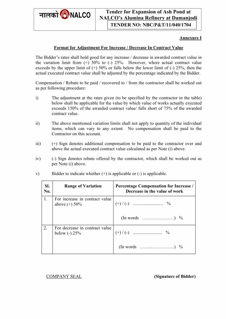
Tender for Expansion of Ash Pond at NALCO’s Alumina Refinery at Damanjodi
TENDER NO: NBC/P&T/11/040/1704
Annexure I
Format for Adjustment For Increase / Decrease In Contract Value
The Bidder’s rates shall hold good for any increase / decrease in awarded contract value in the variation limit from (+) 50% to (-) 25%. However, where actual contract value exceeds by the upper limit of (+) 50% or falls below the lower limit of (-) 25%, then the actual executed contract value shall be adjusted by the percentage indicated by the Bidder.
Compensation / Rebate to be paid / recovered to / from the contractor shall be worked out as per following procedure:
i) The adjustment at the rates given (to be specified by the contractor in the table) below shall be applicable for the value by which value of works actually executed exceeds 150% of the awarded contract value/ falls short of 75% of the awarded contract value.
ii) The above mentioned variation limits shall not apply to quantity of the individual items, which can vary to any extent. No compensation shall be paid to the Contractor on this account.
iii) (+) Sign denotes additional compensation to be paid to the contractor over and above the actual executed contract value calculated as per Note (i) above.
iv) (-) Sign denotes rebate offered by the contractor, which shall be worked out as per Note (i) above.
v) Bidder to indicate whether (+) is applicable or (-) is applicable.
Sl. No.
Range of Variation Percentage Compensation for Increase / Decrease in the value of work
1. For increase in contract value above (+) 50% (+) / (-) ........................... %
(In words …………………) %
2. For decrease in contract value below (-) 25% (+) / (-) .......................... %
(In words ……..……………) %
COMPANY SEAL (Signature of Bidder)
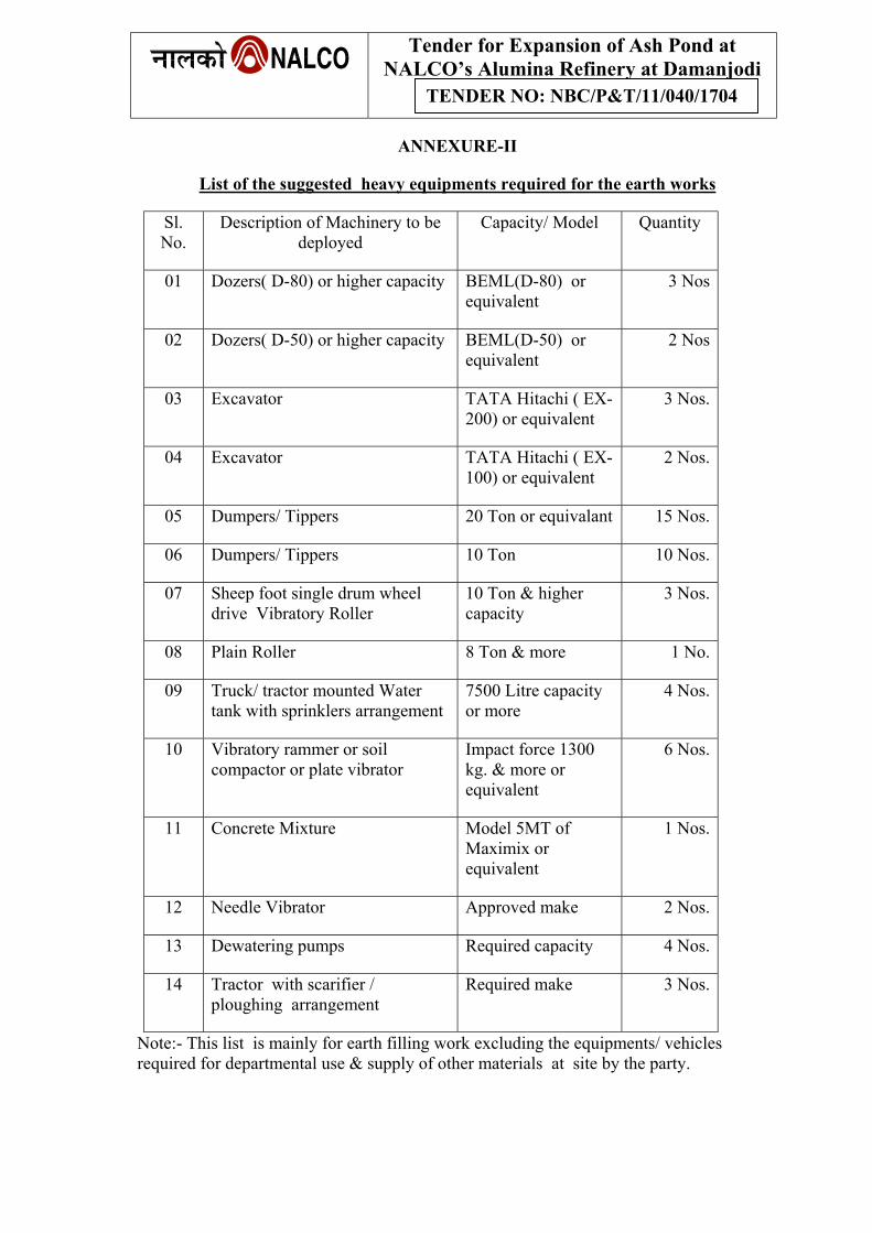
Tender for Expansion of Ash Pond at NALCO’s Alumina Refinery at Damanjodi
TENDER NO: NBC/P&T/11/040/1704
ANNEXURE-II
List of the suggested heavy equipments required for the earth works
Sl. No.
Description of Machinery to be deployed
Capacity/ Model Quantity
01 Dozers( D-80) or higher capacity BEML(D-80) or equivalent
3 Nos
02 Dozers( D-50) or higher capacity BEML(D-50) or equivalent
2 Nos
03 Excavator TATA Hitachi ( EX-200) or equivalent
3 Nos.
04 Excavator TATA Hitachi ( EX-100) or equivalent
2 Nos.
05 Dumpers/ Tippers 20 Ton or equivalant 15 Nos.
06 Dumpers/ Tippers 10 Ton 10 Nos.
07 Sheep foot single drum wheel drive Vibratory Roller
10 Ton & higher capacity
3 Nos.
08 Plain Roller 8 Ton & more 1 No.
09 Truck/ tractor mounted Water tank with sprinklers arrangement
7500 Litre capacity or more
4 Nos.
10 Vibratory rammer or soil compactor or plate vibrator
Impact force 1300 kg. & more or equivalent
6 Nos.
11 Concrete Mixture Model 5MT of Maximix or equivalent
1 Nos.
12 Needle Vibrator Approved make 2 Nos.
13 Dewatering pumps Required capacity 4 Nos.
14 Tractor with scarifier / ploughing arrangement
Required make 3 Nos.
Note:- This list is mainly for earth filling work excluding the equipments/ vehicles required for departmental use & supply of other materials at site by the party.
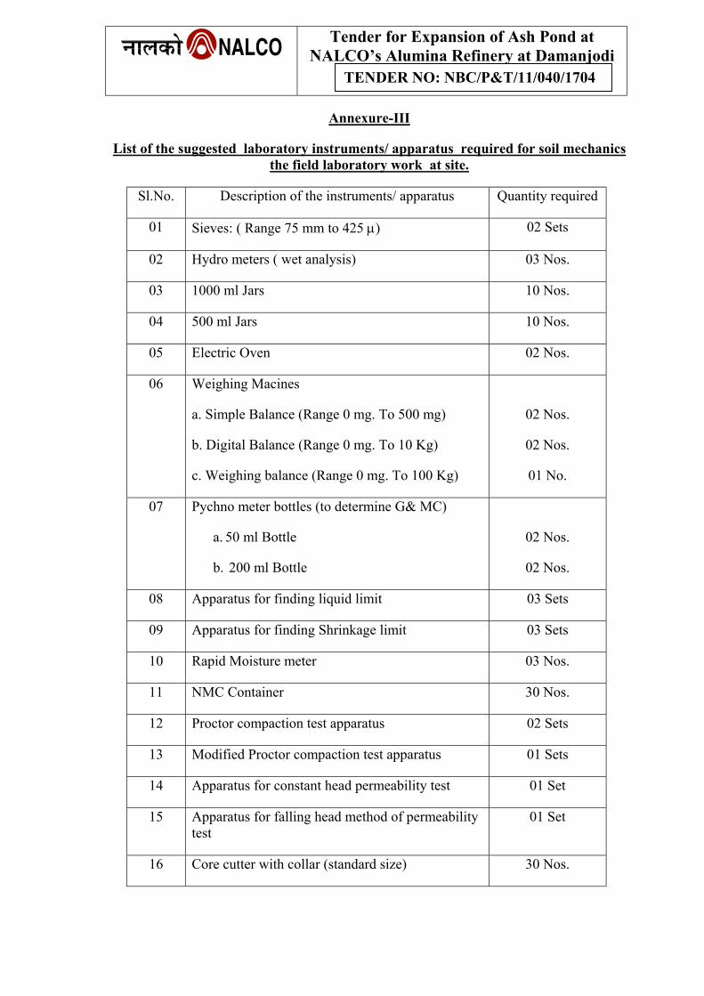
Tender for Expansion of Ash Pond at NALCO’s Alumina Refinery at Damanjodi
TENDER NO: NBC/P&T/11/040/1704
Annexure-III
List of the suggested laboratory instruments/ apparatus required for soil mechanics the field laboratory work at site.
Sl.No. Description of the instruments/ apparatus Quantity required
01 Sieves: ( Range 75 mm to 425 µ) 02 Sets
02 Hydro meters ( wet analysis) 03 Nos.
03 1000 ml Jars 10 Nos.
04 500 ml Jars 10 Nos.
05 Electric Oven 02 Nos.
06 Weighing Macines
a. Simple Balance (Range 0 mg. To 500 mg)
b. Digital Balance (Range 0 mg. To 10 Kg)
c. Weighing balance (Range 0 mg. To 100 Kg)
02 Nos.
02 Nos.
01 No.
07 Pychno meter bottles (to determine G& MC)
a. 50 ml Bottle
b. 200 ml Bottle
02 Nos.
02 Nos.
08 Apparatus for finding liquid limit 03 Sets
09 Apparatus for finding Shrinkage limit 03 Sets
10 Rapid Moisture meter 03 Nos.
11 NMC Container 30 Nos.
12 Proctor compaction test apparatus 02 Sets
13 Modified Proctor compaction test apparatus 01 Sets
14 Apparatus for constant head permeability test 01 Set
15 Apparatus for falling head method of permeability test
01 Set
16 Core cutter with collar (standard size) 30 Nos.

Tender for Expansion of Ash Pond at NALCO’s Alumina Refinery at Damanjodi
TENDER NO: NBC/P&T/11/040/1704
17 Apparatus for Tri-axial shear test with Bishop’s pore water pressure measuring arrangement
01 Set
18 Consolidation test apparatus( three gauges unit)
18 Slum test Apparatus 01 Set
19 Compressive testing machine 01 Set
20 Vibro Sieve 03 Sets
Tender for Expansion of Ash Pond at NALCO’s Alumina Refinery at Damanjodi
TENDER NO: NBC/P&T/11/040/1704
TENDER
FOR
EXPANSION OF ASH POND AT NALCO’s ALUMINA
REFINERY AT DAMANJODI
TECHNICAL SPECIFICATIONS
Tender for Expansion of Ash Pond at NALCO’s Alumina Refinery at Damanjodi
TENDER NO: NBC/P&T/11/040/1704
1. TECHNICAL SPECIFICATIONS FOR EARTH DAM 1.1 GENERAL SPCIFICATION: 1.1.1 Bench Marks:
Before starting any work, the contractor shall erect a permanent benchmark, reference line a check profiles at convenient positions approved by the Engineer-in-Charge. The benchmark shall be 20 Cm x 20 Cm x 60 Cm with 40 Cm embedded underground an 20 Cm above the ground. The top surface of the benchmark shall be horizontal and plain. The works “B.M.” with R. L. shall be conspicuously carved and painted on the benchmark. The reference line shall comprise of a base line properly dag-belled on the ground with number of masonry pillars suitably spaced. The check profiles shall be of such materials and shall be located at such places as to ensure execution of all slops, steps and elevation, to the profile or profiles indicated in the approved drawings or as directed by the Engineer-in-Charge.
1.1.2 In the case of spread out works several benchmarks, reference lines and check
profiles as may be necessary shall be constructed by the Contractor as directed by the Engineer-in-Charge.
1.1.3 All materials and labour for setting out works including construction of bench
marks, reference lines, check profiles and surveys required for setting out works, as may be required at the various stages of the construction works, shall be supplied or made available by the Contractor at the Contractors cost.
1.1.4 Cross Section:
Immediately prior to the beginning of the work, cross sections of the existing ground level at every fifteen meters, normal to the axis of the dam shall be taken all over base and seating of the dam for sufficient distance outside limits. Levels on this cross section will be taken at 5 meters intervals.
1.1.5 These cross sections shall be taken and plotted in the ink and shall be binding on
the parties after they are signed, both by the Contractor and Engineer-in-Charge. These cross sections shall form the basis of all future measurements and payments on the area.
1.1.6 Payments:
No payment shall be made to the Contractor for this item. The rate for individual items of work under the contract shall include the cost of setting out works and all other items indicated above.
1.2 PREPARATION OF WORK AREAS 1.2.1 Clearing & grubbing operations shall be performed in excavation areas,
embankment areas, borrow areas including a 6 M wide strip measured beyond and contiguous to the limit lines of the areas. These sites should be cleared of all trees, stems, roots, rubbish, bushes and other objectionable materials.
Such materials from clearing operations shall be burnt, removed from the site of work or otherwise disposed off as approved. All the materials to be burnt shall be
Tender for Expansion of Ash Pond at NALCO’s Alumina Refinery at Damanjodi
TENDER NO: NBC/P&T/11/040/1704
piled neatly and when in a suitable condition, shall be burnt completely. Piling for burning shall be done in such a manner and in such location as to cause least fire risk. The burning shall be so thorough that all the materials are reduced to ashes. Special precautions shall be taken to prevent fire from spreading to the areas beyond limits to the areas specified and suitable equipment and supplies for preventing and suppressing fires shall be available at all times.
1.2.1.1 Payments:
No separate payment will be made for this and the same will be included in the item of works in schedule of rates and quantities and bids.
1.2.2 Care & Diversion:
In case care and diversion works are considered necessary, the contractor shall construct and maintain such temporary works to make the work area clear of water. The contractor shall pump out all water from the work area and shall keep the foundations free from water while excavating and preparing the foundation etc. The Contractor shall not be entitled for any claim or additional compensation or payment for damages due to water leaking through, under or around temporary bunds.
1.2.2.1Payment:
No separate payment shall be made for construction of temporary bunds and dewatering and the same shall be included in the corresponding items of work in schedule of rates and quantities and bids.
1.3 Detailed Specification of Earth Dam: 1.3.1 Stripping:
The entire areas of embankment including a 3 M wide strip beyond and contiguous with the areas of embankment proper as shown in the drawings shall be stripped to a sufficient depth, as directed, to remove all unsuitable materials. The unsuitable materials shall include all debris, top soil, vegetable matter including roots, loose rock, mounds of earth & boulders, organic silt, swamp materials and other perishable or objectionable materials that are unsuitable for use in permanent construction or that might interfere with the proper bonding of the embankment with the foundation or the proper compaction of the materials in the embankment or that may be otherwise objectionable.
The stripping shall be kept in advance of other items of works to ensure that no undesirable material will get mixed with approved embankment material and to enable proper inspection and measurement. Materials from stripping operation shall be disposed off beyond 60 M from the to of the dam in such a way as not to detract from the finished appearance of the project nor interfere with the accessibility of the structure for operation where required. The waste piles shall be leveled and trimmed to reasonably regular lines. The useful material obtained during excavation shall be suitably utilized either immediately or after stock piling as pr specification of item described later and directed by the Engineer-in-Charge.
Tender for Expansion of Ash Pond at NALCO’s Alumina Refinery at Damanjodi
TENDER NO: NBC/P&T/11/040/1704
1.3.1 Measurements & Payments: (a) Immediately prior to the beginning of the work, after the jungle clearance has
been done, accurate across section of the existing ground level at every 15 M interval or closer where necessary and normal to the axis of the dam shall be taken over the area to be excavated and for sufficient distance outside the limits of excavation, levels on these cross sections will be taken at 5 meters. Final sections along the same lines after the benching or stripping is completed shall be taken. Volume shall then be computed for materials excavated and recorded.
(b) The payment for the work shall be based on measurement for the actual work
recorded in public meter units. It shall include all items like excavations, dressing of the benches and foundations, rehandling and removal of materials from the sites including all leads and lifts etc., as described in the schedule of quantities and bids.
1.3.2 CUT OFF TRENCH 1.3.2.1 Excavation of cut off trench under Dam Embankments:
The cut off trench as shown in the drawings shall be excavated in the foundation to the established lines and grades. The alignment and cross section shown in the drawings will be subject to such changes as may be found necessary by conditions disclosed by the excavations. Accurate trimming of the slopes of the excavation will not be required, but excavation shall conform as closely as practicable to the established lines and grades.
1.3.2.2 Where excavation of cut off trench extends below rock, such blasting procedure
shall be adopted in order to the excavation reaches within about 90 Cms of the final levels, no blasting shall be permitted if in the opinion of the Engineer-in-Charge, such blasting will shatter and disturb the rock below foundation. No blasting shall be carried out within 20 M of the area already grouted. In such cases rock excavation should be completed by chiseling and wedging etc.
1.3.2.3 Material excavated from the cut off trench:
This material, if suitable, shall be used in the embankment either immediately or after stock piling as convenient. The suitability or otherwise of the material and zone of the embankment in which it is to be placed will be determined by the field laboratory and prescribed by the Engineer-in-Charge. Material excavated from cut off trench shall not be placed in the embankment till the foundation for the embankment has been cleared, stripped and prepared as specified and adequate arrangement made for watering and rolling the layers of earth fill in the embankment. This material shall be subject to the same degree of embankment control as for the material obtained from the borrow pits. Excavated materials, which are unsuitable for use or are in excess of dam embankment requirements or other earthwork requirements shall be disposed off as directed by the Engineer-in-Charge.
Waste piles shall be located immediately beyond the disposal of stripped material where they shall not interfere harmfully with the natural flow of stream or with the flow of water to or from the spillway or outlet works and where they will neither detract from the appearance of the completed project nor interfere with
Tender for Expansion of Ash Pond at NALCO’s Alumina Refinery at Damanjodi
TENDER NO: NBC/P&T/11/040/1704
the accessibility of the structure for operation. Where required the waste piles shall be leveled and trimmed to reasonably regular lines.
1.3.2.4 Removal of water from Foundation Excavation:
The method of removal of water from foundation excavation shall be efficient and effective. Where the excavation for cut off trench in the foundation extends below the water table, the portion below the water table shall be dewatered in advance of excavation.
The dewatering shall be accomplished in a manner that will prevent loss of fines from the foundations, will maintain stability of the excavated slopes and bottom of cut off trench and will result in all construction operations being performed in dry conditions. The use of sufficient number of properly screened wells or other equivalent methods is approved for dewatering shall be adopted. The seepage along the bottom of the cut off trench shall also be controlled which may require supplementing the dewatering systems by pip pumped. Such pipe drains shall be of uniform diameter for each run and shall be provided with grout connections and returns at 15 M intervals and shall be embedded in reasonably well-graded gravel or like material.
During placing and compacting of the impervious materials in the cut off trench the water level at every point in the cut off trench shall be maintained below the bottom of the earth fill until the compacted fill in the cut off trench at that point has reached a depth of 3 M after which water level shall be maintained at least 1.5 M below the top of compacted fill. When the fill has been constructed to an elevation, which will permit the dewatering systems to maintain determined by the Engineer-in-Charge to pipe drains including surrounding gravel shall be filled with grout composed of water and cement or clay.
1.3.2.5 Back filling of cut off trench:
Cut off trench shall be filled back by the impervious earth as identified by engineer-in-charge, and placed in the continuous approximately horizontal layers not more than 15 Cm in thickness after being rolled under optimum moisture contents. Higher thickness of layers may also be permitted, if suitable compaction units such as vibratory compactors are used to give the required density under optimum moisture content. The extent of thickness of layer shall be determined in the field by laboratory test.
1.3.2.6 Measurements & payments:
(a) For this purpose grid levels at the ground at 5 M or closer intervals will be taken after stripping and before commencement of the cut off trench and after the final excavation of the cut off trench. Payments will be based on the contents of the cut off finally approved on excavated sections.
For wet excavation and dewatering, no separate payment will be made and the same will be included in the respective items in the schedule of quantities & rates, similarly rate will include all leads & lifts of disposal & shoring wherever necessary.
Tender for Expansion of Ash Pond at NALCO’s Alumina Refinery at Damanjodi
TENDER NO: NBC/P&T/11/040/1704
(b) Payments for the back filling of the cut off trench shall be made in the way as for the impervious clay core of the embankment of the dam.
Payment shall be made as per actual measurements of work done at unit rate of one cut and shall include all items of work including excavation of earth and its transportation, braking clods, picking of roots, leveling and laying, compaction by mechanical means, of earth. No extra payment for dewatering shall be made and same will be included in respective items of schedule of quantities and rates. For running and completed works payments will be made as explained in Para 1.3.4.12 below.
1.3.3. Borrow Areas: 1.3.3.1 All materials required for the construction of embankment and backfill for cut off
trench shall be obtained from designated borrow areas as shown in drawings or as identified by the engineer-in-charge.
The limits of borrow areas to be used in the various zones of embankment shall be flagged in the field and material from each borrow area shall be placed only in the zones for which it has been specified.
The depth of cut in all borrow areas will be designated by the Engineer-in-Charge and the cuts shall be made to such designated depths only. Shallow cuts will be permitted in the borrow areas, if unstraitified material with uniform moisture contents is encountered. Each designated borrow area shall be fully exploited before switching over to the next designated borrow pit. Haphazard exploitation of borrow area shall not be permitted. The type of equipment used and the operations in the excavation of materials in borrow areas shall be such as will produce the required uniformity of mixture of materials for the embankment.
Borrow pits shall not be opened within a distance of ten times the height of the dam embankment from the upstream and downstream toes. Borrow pits shall be operated so as not to impair the usefulness or mar the appearance of any part of the work or any other property. The surface of wasted materials shall be left in a reasonably smooth and even condition.
1.3.3.2 Preparation of borrow areas:
All areas required for borrowing earth for embankment shall be cleared of all trees and stumps, roots, bushes, rubbish and other objectionable material. Particular care shall be taken to exclude all organic matter from the material to be placed in the dam embankment. All cleared organic materials shall be completely burnt to ashes or disposed off as directed. The cleared areas shall be maintained free of vegetable growth during the progress of the work.
1.3.3.3 Stripping of borrow areas:
Borrow area shall be stripped of topsoil, sod and any other matter which is unsuitable for the purpose for which the borrow area is to be excavated. Stripping operations shall be limited only to designated borrow areas. Materials from stripping shall be disposed off in exhausted borrow areas or in the approved adjacent areas, as directed.
Tender for Expansion of Ash Pond at NALCO’s Alumina Refinery at Damanjodi
TENDER NO: NBC/P&T/11/040/1704
1.3.3.4 Borrow areas watering: Borrow area watering will be done by the Contractor wherever necessary and in the manner considered necessary by the Engineer-in-Charge.
The initial moisture content of material in the borrow area shall be estimated with the help of laboratory tests. The optimum moisture content for the materials in the particular borrow areas shall be obtained from the field laboratory. From the optimum moisture content and initial moisture content the amount of additional water required shall be decided.
The required additional moisture so decided shall be introduced into the borrow areas by watering well in advance of the excavation to ensure uniformity of moisture content. If in any location of a borrow area before or during excavation, there is excessive moisture, steps shall be taken to reduce the moisture to secure the material with moisture content closest to the optimum by excavating drainage ditches by allowing adequate time for drying or by any other means. To avoid formation of pools in the borrow areas during excavation, operations, drainage ditches from borrow areas to the outer shall be excavated wherever necessary.
1.3.3.5 Stock Piling:
Stock piling shall be done at approved locations only. Before any area is used for stock piling, it shall be cleared and stripped of all vegetation and top soil as necessary to prepare the stock pile area.
Stock piling of fill materials by end dumping the material down a sloping face/chute shall not be permitted if segregation of the material takes place.
Any material, particularly the materials for impervious cores, when stockpiled shall be protected from being rendered less suitable for placement in the fill due to weathering effects viz., drying, over watering due to rain etc.
1.3.3.6 Payments:
No payments will be made for any of the above works, as these will be covered in the overall rate of earthwork in the dam embankment.
1.3.4 Dam Embankment: 1.3.4.1 General:
The embankment shall be constructed to the lines and grades shown in the drawings. Placement of fill on the embankment as shown in the drawings shall be performed in an orderly sequence and in an efficient and workman like manner, so as to produce an embankment of such qualities of density, strength and permeability as will ensure the highest practicable degree of stability and performance of the whole dam embankment.
No bushes, roots, sods or other perishable or unsuitable materials shall be placed in the embankment. The suitability of each part of the foundation for placing embankment materials thereon and of all material for use in embankment construction will be determined by the field laboratory.
Tender for Expansion of Ash Pond at NALCO’s Alumina Refinery at Damanjodi
TENDER NO: NBC/P&T/11/040/1704
The embankment for each zones shall be maintained in continuous and approximately horizontal layers which are programmed for construction in that season.
1.3.4.2 Preparation of Foundation:
Foundation preparation shall be done subsequent to stripping and excavation, if any. No material shall be placed in any section of the earthfill portion of the dam embankment until the foundation for that section has been dewatered, suitably prepared and has been approved by the Engineer-in-Charge. All portions of excavations made for test pits or other surface investigations and all other existing cavities found within the area to be covered by earthfill or of core and shell zones, which extend below the established lines of excavation for embankment foundation, shall be filled with earthfill of the corresponding zone of the embankment. All test pits within a distance of 10 times the height of dam embankment from the upstream toe shall be filled by impervious material.
Foundations shall be scarified and loosened by means of a plough, ripper or other methods to a depth of about 15 Cms to 20 Cms to t he satisfaction of the Engineer-in-Charge. Roots or other debris turned up during scarifying shall be removed from the entire foundation area for the fill. It shall then be moistened to slightly above the optimum moisture content and compacted by required number of passes of the compaction equipment to the same percentage of compaction as the core. The purpose of higher than optimum moisture is to ensure forcing of the soil into any unseen soft zones just below the surface. The first few lifts of fill for the embankment shall be carefully placed, for the surface will still be rather irregular. If possible heavy rubber tyred rollers should be used for compaction because they will follow the irregular surface and not bridge over small low areas other types of rolling equipment will do. Layers 10 Cms to 15 Cms thick with moisture content 1 to 2 percent above optimum moisture content must be used to ensure uniform compaction and a satisfactory intimate bond between especially under the central core. The layers shall be composed off the most impervious materials, under the central core zone.
The following precautions shall be taken for bonding of embankment of earthdam with bed strata.
1. Loose sand, boulders, debris, and silt coats, stumps of trees etc., shall be removed
from the entire base of the dam. 2. All decomposed, weathered and soft rock shall be removed upto the levels
approved by the engineer-in-charge. 3. Fissures and cracks in rocky beds shall be opened to sufficient depth to facilitate
tamping earth. Narrow cracks shall be filled up with cement mortar (1:3). 4. Sharp projections of the solid rock shall be chamfered. 5. Rocky bed surfaces shall be cleaned by means of high-pressure air and water jet. 6. The rock surface on which the embankment/cutoff trench is to be laid shall be
soaked and coated with a slurry of bentonite or clay plus bentonite. Then the embankment / cutoff trench layer shall be laid with a moisture content 3 to 5 %
Tender for Expansion of Ash Pond at NALCO’s Alumina Refinery at Damanjodi
TENDER NO: NBC/P&T/11/040/1704
wetter than OMC. All such materials and labour for mixing and applying shall be at the cost of the contractor.
1.3.4.3 Earth fill materials:
The materials for the respective zones of embankment shall be obtained from borrow areas designated by the field laboratory, which also will specify the depth of cut in the borrow areas required for obtaining the desired gradation in the materials. In general, all material from a particular borrow area shall be a mixture of materials obtained for the full depth of cut. Where in a borrow area the substratum occurs in well defined layers differing considerably in mechanical analysis so that mixture is not suitable for any particular zone, the materials shall be excavated layer wise by scrapers or other suitable means and the materials placed in the zone for which it satisfied the requirement.
Chemical and physical tests of soils in embankment shall be carried out to ensure that the soil does not contain (a) soluble lime contents (b) soluble salt contents or cohesion less fines, in quantities harmful to the embankments.
1.3.4.4 Placing Earthfill:
The distribution and gradation of the materials throughout the earthfill shall be as shown on the drawings or as directed. That fills shall be free from lenses, pockets, streaks or layers of materials differing substantially in texture or gradation from the surrounding materials. The combined excavation and placing operations shall be such that the materials when compacted in the earthfill will be blended sufficiently to produce the best practicable degree of compaction and stability. Successive loads of materials shall be dumped on the earthfill so as to produce the best practicable distribution of the material. The various zones shall be clearly delineated on the embankment and the materials from the borrow areas placed accordingly.
Particular care shall be taken to ensure that materials are not so placed as will be conducive to the formation of intermittent relatively impervious blankets in the shell zones, which will interfere with the satisfactory drainage.
No stone, cobbles or rock fragments having maximum dimensions of more than 10 Cms (4”) shall be placed in the earthfill. Such stones and cobbles shall be removed either at the borrow pit or after being transported to the embankment but before the materials in the earthfill are rolled and compacted. Such stone and cobble shall be used in the rip-rap or rock toe of the dam embankment, if suitable or as directed. The materials shall be placed in the earthfill in continuous horizontal layers not more than 15 Cms (6”) in thickness after being rolled as herein specified. Higher thickness of layers may also be permitted, if suitable compaction units such as vibratory compactors are used to give required density under optimum moisture content, but in no case the compacted thickness of the layer shall exceed 25 Cms. The extent of thickness of layer shall be determined in the field by laboratory test. During construction, a small transverse slopes from center towards edges should be given to avoid pools of water forming due to rains. If in the opinion of the Engineer-in-Charge the surface of prepared foundation or the rolled surface of any layer of earthfill is too dry or smooth to bond properly
Tender for Expansion of Ash Pond at NALCO’s Alumina Refinery at Damanjodi
TENDER NO: NBC/P&T/11/040/1704
with the layer of materials to be placed thereon, it shall be moistened or worked with harrow, scarifier or other suitable equipment in an approved manner to a sufficient depth to provide a satisfactory bonding surface before the next succeeding layer of earthfill material to be placed. If the rolled surface of any earthfill is found to be too wet for proper compaction of the layer of earthfill material is placed thereon, it shall be raked up and allowed to dry or be worked with harrow, scarfier or any other suitable equipment to reduce the moisture content to the required amount and then it shall be compacted before the next succeeding layer of earthfill material is placed. When compacting the soil against steep rock abutment or walls of masonry or concrete structures, the construction surface of embankment shall be sloped away from the rock or masonry or concrete structures for a distance of 2.5 M to 3.5 M at an inclination of 6:1 or steeper. If the foundation surface is too irregular to allow the use of large roller directly against a structure or rock out-crop, the roller shall be used to compact the soil as close to the structure or the out-crop as possible and the portion of the embankment directly against the rock or the structure shall be compacted with pneumatic hand tampers in thin layers. The moisture content of the earthfill placed against the rock or the structure shall be slightly above the optimum, to allow it to be compacted into all irregularities of the rock and this shall be determined by the field laboratory. In placing the earthfill on rock foundation, the foundation shall first be prepared as detailed earlier. Care shall be taken in placing the first layer of the fill that no damage is caused by the hauling machinery which will get concealed by the spread layer of the fill. Sheep foot rollers shall not be employed for compaction till the thickness of the layers compacted by other means is greater by 30 Cms (12”) than the depth of the foot of the roller drum. The soil for the first layer shall be at moisture content sufficient to enable satisfactory bonding of the fill with the rock surface.
1.3.4.5 Weather Conditions:
Embankment materials shall be placed only when the weather conditions are satisfactory to permit accurate control of the moisture content in the embankment materials. During monsoons before stopping work on embankment, for the continuous spell, the top surface shall be graded and rolled with a smooth wheeled roller to facilitate run off. The contractor shall provide suitable protection works to protect the slopes from erosion from rainwaters. No payment whatsoever will be made for providing such protection works. Prior to resuming work, the top surface shall be scarified and moistened or allowed to dry as necessary and approved by the Engineer-in-Charge for resumption.
1.3.4.6 Moisture Control:
The water content of the earth fill material prior to and during compaction shall be distributed uniformly throughout each layer of materials and it shall be between –2 to +2 % of the optimum moisture content. Moisture determination of soil shall be carried out as per latest I S specifications.
Laboratory investigations may impose some restrictions on the lower limits of the practicable moisture contents on the basis of studies on compaction characteristics of soils in embankment. Hereinafter the term range of optimum practicable moisture content shall refer to the value as described above. As far as practicable,
Tender for Expansion of Ash Pond at NALCO’s Alumina Refinery at Damanjodi
TENDER NO: NBC/P&T/11/040/1704
the material shall be brought to the proper moisture content in the borrow area before excavation. If additional moisture is required, it shall be added by sprinkling water before rolling of a layer. If the moisture is greater than required, the material shall be spread and allowed to dry before starting rolling. Moisture control shall be relatively uniform throughout the layer of material. If necessary, ploughing, disking, harrowing or blending with other materials may have to be resorted to, to obtain uniform moisture distribution. If the moisture content is more or less than the range of optimum practicable moisture content or if it is not uniformly distributed throughout the layer rolling and adding of further layer shall be stopped. Further work shall be started again only when the above conditions are satisfied.
1.3.4.7 Compaction and Watering:
The Contractors shall have to arrange suitable compaction equipment to carry out the compaction. Although equipment shall be deployed on the basis of the requirement at a particular time, the comprehensive list of such equipment is indicated below. The capacities and Nos. of equipments mentioned here are only indicative and for the guidance of the contractors. Contractors shall mobilize equipment of such capacities as are required for carrying out the work.
SL. NO. NAME OF EQUIPMENT
01. Single drum wheel drive Vibratory sheep foot Roller 10 Ton or more capacity.
02. Sheep Foot Roller (Double drum). 03. Crawler tractor 180 HP (for 2 pairs rollers) 04. Crawler tractor 90 HP (for DD rollers) 05. Wheel type tractor (for single drum rollers / scrapper facility) 06. High speed compactors B Equipment for compaction of casing and filter
SL. NO. NAME OF EQUIPMENT 01 Soil Vibratory Rammer/ Compactor of required Capacity. The broad details of equipments for compaction are mentioned below: Compaction Equipment: While the specifications below provide that equipment of a particular type and size is to be furnished and used, it is to be noted that the use of improved compaction equipment shall be encouraged as may be found suited to the prevailing site conditions and the programme of construction. Tamping Rollers: Tamping rollers used for compacting earthfill shall conform to the following requirements: 01. Roller Drums:
Double drum sheep foot roller shall be used for compaction. Each drum of a roller shall have an outside diameter not less than 142.25 Cms (56 inches) and shall not be less than 122 Cms (48 inches) in length. The space between two adjacent drums when
Tender for Expansion of Ash Pond at NALCO’s Alumina Refinery at Damanjodi
TENDER NO: NBC/P&T/11/040/1704
on level surface shall not be less than 30 Cms (12 inches) and not more than 38 Cms (15 inches). Each drum shall be free to pivot about an axis parallel to the direction of travel.
02. Tamping Feet:
The total number of feet per drum shall be 88. At least one tamping feet shall be provided for 867 Cm2 (150 Sq inches) of the drum surface area. The length of each tamping foot from the outside surface of the drum shall be maintained at not less than 18 Cms (7 inches). The cross sectional area/bearing surface area of each tamping foot shall not be less than 25.80 Sqcm (4 Sq inches), nor more than 64.5 Sq cm (10 Sq inches) at plane normal to the axis of shank 125 Cm (6”) from surface.
03. Roller Weight:
The weight of the roller when fully leaded shall not be less than 7091 Kgs (15,500 lbs) and the ground pressure when fully loaded shall not be less than 40 Kg/Cm2 (570 PSI). The loading used in the roller drum shall be required to obtain the desired compaction. The tractor used for pulling shall be 50 HP to 65 HP power to pull the rollers satisfactorily at a speed of 4 Kms per hour when the drums are fully loaded with wet sand ballast. During operation of rolling, the spaces between the tamping foot shall be kept clear of materials sticking to the drum which could impair the effectiveness of the tamping rollers.
1.3.4.8 Rolling:
When each layer of material has been conditioned so as to have the proper moisture content uniformly distributed throughout the material, it shall be compacted by passing the tamping roller. The exact number of passes shall be designated by the field laboratory after necessary test. The layers shall be compacted in strips overlapping not less than 0.6 M. The rollers or loaded vehicle shall travel in a direction parallel to the axis of the dam. Turns shall be made carefully to ensure uniform compaction. Rollers shall always be pulled. Density tests shall be made after rolling. Dry density attained shall satisfy the compaction standards specified in “Criteria for control of compacted Dam Embankment” of U S Bureau of Reclamation (Table 4, Page 275 of Earth Manual of Bureau of Reclamation) reproduced and attached as Annexure II.
1.3.4.9 Tamping:
Rollers will not be permitted to operate within 1.0 meter of concrete and masonry structures. In location where compaction of the earthfill material by means of roller is impracticable or undesirable, the earthfill shall be specially compacted as specified herein at the following locations:
(i) Portions of the earthfill in dam embankment adjacent to masonry structure and
embankment foundations designated on the drawing as specially compacted earthfill.
(ii) Earthfill in dam embankment adjacent to steep abutments. (iii) Earthfill at locations specially designated.
Earthfill shall be spread in layers of not more than 10 Cms in thickness when loose and shall be moistened to have the required moisture content as specified
Tender for Expansion of Ash Pond at NALCO’s Alumina Refinery at Damanjodi
TENDER NO: NBC/P&T/11/040/1704
when each layer of material has been conditioned to have the required moisture content, it shall be compacted to the specified density at special rollers, mechanical tampers or by other approved methods and all equipment and methods used shall be subject to approval based on evidence of actual performance and field compaction tests. The moisture control and compaction shall be equivalent to that obtained in the earthfill actually placed in the dam embankment in accordance with the specifications.
Work of compaction specified above will be carried out by the Contractor and no payment will be made separately for this purpose as the rates quoted are inclusive of this activity.
Watering:
Watering on dam embankment shall be carried out by the Contractors but no separate payment shall be admissible as the individual items of work include this activity also.
1.3.4.10 Dressing Slopes:
The outside slopes of the embankment shall be neatly dressed in lines and grades as per the specification in Drawing by making bench/key joints in old dam slope surface for placement of fill progress. Compaction shall extend over the full width of the embankment and material in earth slopes shall be compacted as for the rest of structure. To ensure proper compaction on the edge, the cross section of the filling during construction shall be kept suitably wider ( more than 750 mm extra width and the cross section dressed to the designed requirement after compaction, for which no extra payment will be made along with benching/key joints of earth in old dam slope for bonding and the cost of the same shall be included by the contractor in the per cubic meter rate of completed item of earth work as dealt with later under “measurements and payments”.
All humps and hollows varying more than 15 Cm (6”) from the lines of the embankment shall be regarded. Material used to fill depression shall be thoroughly compacted and bonded to the original surface. Slopes shall be maintained until final completion and acceptance. Any material that is lost by rains, weathering or other cause shall be replaced by the contractor at his cost.
1.3.4.11 Settlement Allowance:
In the earthfill embankment settlement allowance 2% shall be provided. The base width of the dam will not be increased to maintain the design slopes indicated in the drawings for the additional heights as settlement allowance, but the following procedure will be adopted:
Settlement Allowance will be calculated at various levels where the slop is to be changed and the elevations including settlement allowance will be derived, the embankment widths at the designed levels remaining same. The edges of embankment a the increased elevations (including settlement), when joined with the point where the slope has changed earlier below shall give the slope to be adopted for construction.
Tender for Expansion of Ash Pond at NALCO’s Alumina Refinery at Damanjodi
TENDER NO: NBC/P&T/11/040/1704
If the embankment is raised in more than one season provision for settlement shall be made in the last season’s construction by slight steeping of slopes near the top.
1.3.4.12 (a) Measurements & Payments of Earth Work on Dam & cutoff trench:
The work shall be measured on the basis of the cross sections. Initial cross sections for this will be the ones taken after stripping and in accordance with Para 1.2.2. The cross sections will be taken at an interval of 15 M (50 Sft) or at closer distances as found necessary. The gross quantity of embankment work, cutoff trench etc., as the case may be will be based on these cross sections in which also will be indicated the separate zones of finished embankment, cutoff trench, filter material, pitching etc., for facility of arriving at the correct quantities. The lines demarcating the zones on the cross sections shall confirm to respective typical sections, except where departures from these are specially permitted by the Engineer-in-Charge. Running measurements for any subsequent bill will be the overall sectional measurements minus the sectional running measurements up to the previous running bill and so on. (b) Running measurements for embankment filling material of soil will be paid at
90% of the tendered rate up to 50% of the quantities given in the schedule of quantities & rates. The quantities in excess of 50% will be paid at 95% of the tendered rates.
(c) Final measurements will be recorded on cross sectional basis. Foundation plan
with relevant cross sections of the dam showing dimensions and levels shall be prepared and got signed by the contractor, in token of the acceptance first before commencement of stripping and again after completion of stripping of dam seat. The final measurements will be based on the accepted foundation plan and relevant cross section and completed section of the dam at the time of taking final cross-section. Payment for the quantities arrived at shall be paid at full tendered rate in final bill.
(d) The contractor shall be allowed to utilize the suitable material obtained from
the items of excavation such as stripping, toe drain, cut off trench, foundations etc., in the dam section and the cost of such materials will be determined in accordance with the rates to be fixed by the Engineer-in-Charge or free of cost. Overall section of the components of the dam shall be measured and paid at the tendered rates.
(e) Cross sections referred to in the above sub-para will be taken after the top
most earth layer is duly compacted at optimum moisture content in accordance with paras 1.3.4.7 of the specifications. Any over section over and above stipulations in para 1.3.4.1 will be ignored and not paid for. Similarly while making running payment suitable deduction will also be made for loose, undressed, uncompacted material on the slope.
(f) In order that proper compaction can be done up to the edges of the designed
section duly increased for settlement and shrinkage as stipulated above, section will be further widened by 45 Cm (18 inches). Subsequently after compaction it will be dressed by trimming the slopes to proper sections so that the surface
Tender for Expansion of Ash Pond at NALCO’s Alumina Refinery at Damanjodi
TENDER NO: NBC/P&T/11/040/1704
on the slopes is also as firm and compact as the top of the embankment. Necessary extra quantities required to be handled for this purpose shall not be paid for extra and is to be included in the rate of earth work for the dam embankment, as already stipulated in para 1.3.4.1.
(g) Apart from the items described in the schedule of quantities, rate payable for
this item will also cover construction, maintenance and removal of all additional haul road and ramps, lighting of work areas during dumping & compaction and removal of all roots, vegetation and other unsuitable and objectionable materials either at the borrow area or at the embankment and unless there is anything specified to the contrary.
The rate for earth work on dam shall include laying of layers in uniform thickness, removal of roots and vegetation, breaking clods and dressing with all leads and lifts.
Payment of final bill shall be made at full tendered rate of earth work for embankment material on the quantities worked out as above.
1.3.4.13 Road Surfaces and PCC curbstones:
Road shall be constructed at the top of earth dam and at the other locations as indicated in the drawings. The roadway shall be as indicated in drawings and connecting to the surrounding road . The construction detail shall be as specified by the Engineer-in-Charge.
The PCC curbstones shall be embedded only after allowing sufficient time for the embankment to undergo the usual post-construction settlement in order to avoid differential settlement.
1.3.4.14 Toe Drains:
Pitched toe drains with filter will be provided throughout the length of dam at the downstream toe of earth dam s indicted in the drawings and as per the details shown therein. Trench drains with suitable material shall be provided where the depth of water below FRL exceeds 15 M. The layers of horizontal filter shall be extended into the toe drains to specified thickness. The filter shall be watered & tamped with hand tampers. The useful excavated material out of the toe drain shall be suitably utilized on the dam as directed by the Engineer-in-Charge.
1.3.4.15 Measurements & Payments:
Measurements shall be taken by measuring independently surface area of the slope and multiplying the same by thickness of various layers of filters. The rates include all leads and lifts of materials of watering and compaction of filter material. Payment for filter material shall be made in square meters at the tendered rates with all leads and lifts.
1.3.5 FILTER AND RIP-RAP: 1.3.5.1 Base Filter Blankets:
Where indicated in the drawings, filter blankets shall be laid on the base under the downstream portion of the earth embankment. The number of layers in filter
Tender for Expansion of Ash Pond at NALCO’s Alumina Refinery at Damanjodi
TENDER NO: NBC/P&T/11/040/1704
blanket and thickness of each layer shall be as specified in the drawing. Filter shall be placed and tamped in such a manner that mixing of filter with foundation or backfill materials will not occur.
The filter material shall consist of clean, sound & well-graded crusher broken aggregate. The material shall be free from debris, bush wood, vegetable matter, decomposed rock and other deleterious matter. The gradation of each filter layer shall meet the following requirement with respect to the material to be protected and also with respect to the adjacent filter layers.
(i) D-15 of the filter__________ = 5 to 40 D-15 of the base material
Provided the filter does not contain more than 5 percent of material finer than 0.074 mm (No.200 sieve).
(ii) D-15 of the filter__________ = 5 or less D-85 of the base material (iii) The grain size curve of the filter shall be roughly parallel to that of the base
material. In the above D-15 is the size at which 15 percent of the total soil particles are finer the percentage being by weight is determined by mechanical analysis. The D-85 size is that at which 85 of the total soil particles are finer. It shall be laid in single layer or in layers as per the drawing. If more than one filter layer is required, the same criteria shall be followed. The finer filter is considered as the base material for selection of the gradation of the coarser filter.
(iv) In order to prevent segregation and bridging of large particles the maximum particles size shall not exceed 75 mm. The requirement for grading of the filter shall be established by the filed laboratory on the basis of mechanical analysis of adjacent materials. Mechanical analysis shall be performed on samples, which have been compacted by the methods equivalent to compaction by rollers so that individual particles of decomposed rock are broken to their final condition in the embankment.
The material brought by the contractor to the site shall be subjected to the aforesaid tests in the laboratories at the project site. The result shall be final and binding and all material not conforming to the requirement so determined shall not be permitted for use on the said works.
1.3.5.2 Placing:
The foundation shall be cleared, striped as specified in para 1.2.1 and 1.2.2 before laying the base filter.
The filter material (mixed gradation) shall b deposited in horizontal layers of thickness not more than 15 Cm (6”) after compaction by approve type of compactors.
Tender for Expansion of Ash Pond at NALCO’s Alumina Refinery at Damanjodi
TENDER NO: NBC/P&T/11/040/1704
The thickness of filter layer shall be increased to 30.48 Cm (12”), if compaction is performed by trends of crawler type tractors, surface vibrators or similar equipment. Thickness of layers shall however, not be more than the penetrating depths of the vibrator, if compaction is performed by internal vibrator. During or immediately prior to compaction the material in each layer shall be thoroughly wetted. The relative density of the compacted material shall be not less than 75% as determined by the Standard U S Bureau of reclamation relative density tests for cohensionless free drainage soils.
The relative density may also be computed using the max. and min. density as follows:
Dd = Yd max. x (Yd – Yd min.) x 100
Yd (Yd max. – Yd min.) Where
Yd max. = Maximum dry density of soil as obtained by the laboratory procedure
Yd min. = Minimum dry density of soil as obtained by the
laboratory procedure and
Yd = The dry density at which the soil is to be placed or the in place dry density
Extreme care shall be taken in placing material in the filter zone as to obtain a fill free from lenses, layers and streaks of segregated materials.
After completion of the filter blanket, the earthfill material shall be placed in 10 Cms. (4”) layers and tamped by hand at optimum moisture or compacted by smooth rollers or power compactors as directed by Engineer-in-Charge. Sheep foot rollers shall not be used till earthwork has been laid and compacted to a thickness of 60 Cms. (24”) over the filter blanket. However, the compaction of earthfill in the initial 60 Cms. (24”) thickness to moisture content and dry density as for the rest of the embankment.
1.3.5.3 Chimney Filter:
Vertical chimney filters / Inclined filters of the dimensions specified in drawings shall be constructed as per the dimensions and at locations as shown in the drawings. Materials used shall be clean, sound and durable and shall be free from silt roots, brush and other impurities. Filter materials shall be laid in 30 Cm layers and shall be compacted by pneumatic tyred rollers or other approved equipment. Materials for filter shall be compacted to obtain a minimum relative density of 70%. The filter shall satisfy the filter criteria. The gradation of the filter materials shall be the same as in para 1.3.5.1 for base filter blankets.
(a) Payments:
Measurement of filter materials shall be taken by measuring independently surface area of slope and multiplying the same by thickness of various layers
Tender for Expansion of Ash Pond at NALCO’s Alumina Refinery at Damanjodi
TENDER NO: NBC/P&T/11/040/1704
of filters at its tendered rates as stipulated in the schedule of quantities and rates. The rate shall include shuttering required for chimney filter.
The rate shall be inclusive of all leads and lifts of material, watering and compaction of the filter material and no separate payment will be made to the Contractor for these works.
1.3.5.4 Rip-Rap on the upstream slope of Embankment:
Rip-Rap shall be hand placed on the upstream slope of the dam embankment. The thickness of rip-rap layer shall be as indicated in the drawings. The thickness shall be measured normal to slope of the embankment.
The rip-rap material shall consist of the most durable rock fragments of approved quality selected for the purpose. The quality of individual rock fragments shall be dense, sound and resistant to abrasion and shall be free from cracks, seams, shale partings, conglomerate bands and other defects that would tend to increase unduly their susceptibility to destruction by water and weathering action. The shape of the individual rock fragment shall be angular, fragment having thickness les than 50% of their maximum dimensions shall not be used as rip-rap. The individual stone (for at least 50% of the surface) laid in rip-rap should weigh at least 75 Kg. These stones shall be evenly distributed over the paved area. No stones shall be placed on edge with the longer dimension normal to the slope. Rock fragments and spalls shall be tightly driven into the interstices to wedge the rip-rap in place and closes direct opening under lying slope. Stone shall be laid in a compact manner beginning at the bottom of the slope.
Rip-rap shall be placed over shield filter laid on the slope of the dams as per the drawing & specification without cutting below the level of designed section along with the fill , so that a minimum of breakdown will occur during placing and spreading.
1.3.5.5 Graded/ shield filter Underneath Rip-Rap:
Graded/shield filters shall be constructed underneath the rip-rap on the upstream of embankment as indicated in the drawings.
The graded filter shall consist of sand and crushed stone as shown in the drawings. Sand used shall be clean, sound and durable and shall be free from silt, roots, bush wood and other impurities. Sand used in the filter shall be of size passing 5 mm screen. Crushed stone used for filter shall consist of rock fragments. The filter shall satisfy the filter criteria as given in 1.3.5.1.
1.3.5.6 Placing Filters:
Before the first layer of filter material is placed, the embankment shall be trimmed neatly to the slope and grades indicated on the drawings to to the designed section not cutting extra for the filters & rip rap thickness. The filter material shall be placed in layers of uniform thickness and care shall be taken to avoid segregation of coarse and fine material in each layer, formation of pockets and mixing of material from one layer with material of another layer or earth fill.
Tender for Expansion of Ash Pond at NALCO’s Alumina Refinery at Damanjodi
TENDER NO: NBC/P&T/11/040/1704
Filter material after laying shall be compacted to 70% relative density by watering and compacting with hand rammers or other suitable mechanical equipments.
Measurements & Payments:
Payment will be made at tendered rate inclusive of all leads and lifts for various items under this para in accordance with above para and with the description given in the schedule of quantities and bids. Measurements shall be taken by measuring independently surface area of the slope and multiplying the same by thickness of various layers of pitching and filters as directed by the Engineer-in-Charge. No payment shall be made to the contractor for watering and compaction.
1.3.5.7 Rock Toe:
The material for rock toe shall consist of the most durable rock fragments of approved quality selected for the purpose. The quality of rock fragments shall be dense, sound and resistant to abrasion and shall be free from cracks, seams, shale parting, conglomerate bands and other defects that would tend to increase unduly their susceptibility to deterioration by water and weathering action. The shape of the individual rock fragments shall be angular. Stones of size les than 0.019 Cum shall not be used in the rock toe. The rock toe shall be constructed of rock fragments obtained from the excavation for permanent construction and from rock source, if necessary. The rock fill material shall consist of rock fragments reasonably well graded as determined by the Engineer-in-Charge up to t he maximum size of available stones.
Successive loads of material shall be dumped so as to secure the best practicable distribution of the materials as determined by the Engineer-in-Charge. To the extent practicable, the larger rock fragments shall be placed on the outer slopes and the smaller rock fragments shall be placed next to the inner portions of the dam embankment. Rockfill shall be placed in approximately horizontal layers not exceeding 90 Cm. in thickness. The rock fragments need not be hand placed but shall be dumped and roughly leveled, in a manner to maintain a reasonably uniform surface and ensure that the completed fill will be stable and that there will be no unfilled space within the fill. The voids between the bigger stones after rough leveling shall be filled with rock fragments of smaller size only in quantities enough to fill up the voids. The exposed surfaces of the rock toe shall be neatly finished as to conform to the designed lines and grades as shown in the drawings.
1.3.5.8 Turfing on Downstream Slope:
Turfing shall be done on downstream slope of embankment with pad / doob grass or as decided by Engineer-in-charge, providing the grass turfing with selected sods by collecting from approved area with in all lead. Cutting the grass pad / sod with minimum 50mm of orginal soil with roots, turfing the same in slope of earthen dams of all height including loosing the bottom surface of turfing & placing loose earth with 150mm thick after breaking the clods if any & mixing with sludge / dry cow dung or approved manure in ratio 8:1 ( 8 parts of loose soil / clay / earth by volume to 1 part of dry cow dung / sludge / manure by volume ) with necessary sprinkling of water before placing the grass pad and hand compacting with wooden hammers without damage to the green grass pad. The necessary watering and
Tender for Expansion of Ash Pond at NALCO’s Alumina Refinery at Damanjodi
TENDER NO: NBC/P&T/11/040/1704
putting of cow dung / manure as per requirement time to time for maintenance of the turfing for one year as shown on drawings and as directed by the Engineer-in-charge. The rate shall include for all the materials like collection of grass pad, loose approval soil, cow dung / sludge / manure, placing in all lead and lift on the slope maintenance the grass for one year after completion of the contract period along with guarding and removal of obstructionable shrubs, plants, vegetations & termite mould by injecting chemical emulsion (aldrin or equivalent) post constructional antitermite treatment wherever required and directed & repair the whole by the plugging with selected approval hard soil and matching the existing slope / berm and gradient and subsequent returfing if necessary while one year of maintenance. The grass turfing should be maintained after the date of completion of contract for one year. The payment will be made 70% of quoted rates after successfully laying of grass as per specification & balance 30% rate will be released after the completion of the maintenance period of one year. Arrangement surface drainage shall also be made on the downstream slope by providing open drains as shown on the drawings and as directed0 by the Engineer-in-charge. Payment for various items of work shall be made as per provisions in schedule of rates. Rate shall be made as per provision in the schedule of rates. Rates shall include supply of all equipments and materials with all lead and lift, labour, supervisor, watering, compaction etc required to complete the work.
1.3.6 Inspection and Tests:
It is necessary to maintain a thorough check on the quality of fill materials delivered to the dam and that the data and insitu properties of the materials after compaction be obtained for comparison with design assumptions. To achieve these objectives, a programme of fill testing and inspection shall be planned to affect quality control.
1.3.6.1 Scope of Testing and Inspection required:
Field control of fill materials will require visual and laboratory checks. The checks on the effectiveness of placement and compaction procedures will require to be made by field density tests, at prescribed intervals. The control shall be on the method type and/or on an end result basis.
I Before Compaction:
Materials delivered to the fill shall be visually examined and their properties estimated by way of inspection. These checks shall include:
(a) Borrow areas (i) Excavation of borrow areas shall be limited in extent and depth as
indicated on plans. (ii) Estimation of moisture content of materials by visual examination
and feel.
Tender for Expansion of Ash Pond at NALCO’s Alumina Refinery at Damanjodi
TENDER NO: NBC/P&T/11/040/1704
(iii) Samples shall be taken for laboratory analysis in case the soil is of different characteristics.
These inspection checks shall be supplemented by sampling the materials at prescribed minimum intervals and by testing the samples in the laboratory for gradation and moisture content.
(b) Embankment (i) Water content tests shall be carried out in the laboratory while
placing the fill materials. (ii) Moisture content shall be controlled by adding water or aerating the
soil according to laboratory tests.
(iii) It shall be ensured that the methods of dumping, spreading and moisture conditions are such that which results in reducing segregation and/or variation of moisture content to a minimum.
II During Compaction: It is intended that the checks on operations during compaction shall verify:
(i) That the layer thickness of the material is as specified. (ii) That the fill is compacted by the specified number of passes of the
specified machinery.
(iii) That no excessive rutting, weaving or a scaling of the fill occurs during compaction.
III After Compaction:
The condition of the fill after compaction shall be observed and recorded particularly with respect of rutting or weaving. However, the properties of materials after compaction shall be determines primarily by fill density tests. Routing tests on samples taken from constructed embankments shall include, besides density tests, grain size distribution, atterberg limits, permeability and shear and consolidation characteristics.
1.3.6.2 Frequency of Testing:
It will be necessary to carry out sampling and testing of materials before and after compaction at sufficient frequencies so that effective checks on the fill operation are maintained. The testing frequencies proposed should correspond to the frequencies shown in Table-I. However, the actual frequencies shall be adjusted to suit the nature and variability of materials placed and the rate of fill placement.
Testing shall be performed at higher rates than those given in Table-I, during initial stages of placing each zone in order to establish control and testing techniques. Also testing shall be conducted at a higher rate in case of special
Tender for Expansion of Ash Pond at NALCO’s Alumina Refinery at Damanjodi
TENDER NO: NBC/P&T/11/040/1704
problems of control caused by such factors as material variation, equipment performance and of weather.
In addition, these tests shall be made:
1. In areas where the degree of compaction is doubtful.
2. In areas where embankment operations are concentrated.
3. For “record” tests at the locations of all embedded instruments.
Location of insufficient compaction shall cover the following or any other areas so determined by the Engineer-in-Charge.
1. The junction between areas of mechanical tamping and rolled embankment
along abutments or cut off walls. 2. Areas where rollers turn during rolling operations. 3. Areas where too thick a layer is being compacted. 4. Areas where improper water content exists in a material. 5. Areas where less than specified number of roller passes were made. 6. Areas where dirt-clogged rollers are being used to compact the materials. 7. Areas where oversized rock, which has been overlooked is contained in the
fill. 8. Areas where materials have been placed when they contained minor amounts
of frost or at nearly freezing temperatures. 9. Areas that were compacted by rollers that have possibly lost part of their
pallast. 10. Areas containing materials differing substantially from the average.
1.3.6.3 Record and Reports:
Record of borrow area materials and embankment placing operations be maintained in order to have a continuous check on the suitability and availability of fill materials and quality of the fill. Thus, it will be possible to have complete description of materials in any portion of the embankments. The records shall be maintained on the form specified in Annexure II. Annexure II indicates the criteria for control of compaction of dam embankment.
1.3.6.4 Field Test Data:
Records of field test data results should be presented in the form of statistical analysis sheets and summary sheets in order to provide control required for enforcement of statistical requirements of the specifications.
Tender for Expansion of Ash Pond at NALCO’s Alumina Refinery at Damanjodi
TENDER NO: NBC/P&T/11/040/1704
The test data summary sheets and inspection reports be used to form the basis of construction control report, which should be issued from the site at fortnightly intervals during construction season. The report would contain narrative accounts of the progress and problems of fill construction, statistical analysis of test data and photographs of the fill operations.
1.3.6.5 Embankment Test Section:
Placement of compaction methods specified will have to be verified by the test embankment section to be built prior to starting of fill operations or at an early stage of dam construction. The initial stage of dam construction itself could be made to serve the purpose of test embankments. The test sections referred herein shall be used to establish:
(a) Layer thickness of fill materials. (b) Optimum practicable moisture content. (c) Number of passes of sheep foot roller or weight of vibratory rollers vis-à-vis
of passes for effective compaction.
When an appreciable change in material occurs, additional test sections shall be made during construction. The procedure for construction of test embankment section is as follows:
(a) Select a location on the embankment where uninterrupted placing
operations are being performed. This area 15 M by 30 M (about 50 ft. x 100 ft.) should be carefully marked and referenced so that its limits will be easily recognized. In order to expedite the determination of moisture content to be used, more than one test section may be established on the embankment at the same time.
(b) During construction of the test section, which will most probably continue
for several shifts, a complete record of the procedure should be kept. This record should include the number of layers placed, the spread thickness of each layer, the moisture content, at which the materials were rolled, the designation (No.1, No.2 etc.,) of the rollers used, the condition of the rollers (clean or dirty), the action of the materials being rolled (such as wavy under the rollers, the amount of penetration of the roller teeth after different number of roller trips etc.,) and the borrow pit location from which the materials came.
(c ) Check the roller to make certain that they meet all the requirements of the
specifications.
(d) Determine the required spread thickness of layer that will compact to the specified thickness after rolling specified number of times and maintain this thickness as long as number of roller passes is kept the same.
(e) Using the available data from borrow pit investigations of the materials to
be used in the test section the optimum moisture content as determined by
Tender for Expansion of Ash Pond at NALCO’s Alumina Refinery at Damanjodi
TENDER NO: NBC/P&T/11/040/1704
laboratory tests will be known and 3 percent less than this moisture content should be used in the first 3 or 4 layers rolled.
(f) After 3 or 4 layers have been placed at 3 percent less than the laboratory
optimum moisture content, field density test should be made throughout the section. These tests should be made for at least each 93 Sqm (1000 Sqft.) of test section area and should be so distributed over the area that they will detect the effects of different compaction conditions encountered during construction. For example, if the section is located near an abutment, certain parts of the area will receive more compaction from track travel than others, hence some tests should be made in the portion compacted only by the rollers and so reported.
(g) The next step is to compact another 3 or 4 layers at the moisture content
slightly higher (1 percent or 2 percent) than the moisture content previously used, maintaining the same rolled thickness of layer and number of roller passes, as above. Field density tests are again made over the test section.
(h) if the resulting field dry densities of material passing the No.4 sieve from
(g) above shown an increase with increase of moisture, again by another 1 percent or 2 percent, repeat the test. If an increase in moisture results in a decrease in field density then place the next layers slightly dry of the original moisture content use and repeat the test. This procedure is nothing more than developing on the embankment a moisture density relation or compaction curve for a certain roller, thickness of layer and a given number of roller trips. If special studies during investigation have indicated that the material being tested should be placed within certain moisture limits or if the moisture limits to be used have been specified, the procedure outlined above should include tests at these moisture contents both greater and smaller than the specified limits.
(i) The roller compaction curve is now compared with the standard laboratory
compaction curve. If the field density of materials passing the No.4 sieve (from the roller curve) is greater than the standard compaction density at the specified moisture content, the best section should be continued decreasing the number of roller trips while maintaining the specific desirable moisture content until the most economical compactive effort is determined. When the roller trips are decreased, the required spread thickness of layer that will compact to the specified thickness of compacted material should be reckoned.
(j) All works connected with the embankment test section will be done by the
Contractors under the supervision and direction of Engineer-in-Charge. No separate payment shall be made for this work.
2.0 TECHNICAL SPECIFICATION FOR GROUTING 2.1 General:
The principal objective of foundation grouting is to establish an effective barrier to seepage, thereby reducing hydrostatic up-lift under the structure. A secondary
Tender for Expansion of Ash Pond at NALCO’s Alumina Refinery at Damanjodi
TENDER NO: NBC/P&T/11/040/1704
objective is to consolidate the rock under the structure and thus secure a more unified and monolithic foundation. The procedure to be followed in grouting a foundation is governed by the height of the structure and the characteristics of the rock. Any plan for a grouting programme can only be tentative and must be modified to suit actual conditions after grouting operations are started.
The general plan for grouting the foundation rock under the dam provides for preliminary low pressures, shallow grouting to be followed by double line high pressure deep grouting. “High Pressure” and “low pressure” are relative terms only. The pressure that are used are usually the maximum that will ensure the complete filling of all joints, crevices and voids without causing any up-lift or lateral displacement of foundation rock.
2.1.1 The work of low pressure and high pressure grouting shall include but may not be
limited to the following:
(ii) Surface treatment like cleaning. (iii) Grouting test holes within the grouting area. (iv) Casing of drill holes as required and testing as required by the conditions
encountered at the site of the grout holes and grouting the rock (both at low and high pressure).
(v) Installation and maintenance of special recording instruments required for the work covered by this section.
(v) Clean up of the grouted areas.
During drilling, testing and grouting operations, the rock surface in the grout area and the surrounding ten-meter strip shall be kept clean and free of oil, grease, drill cuttings, muck, grout, cement pozzolan, excess water or any kind of waste.
Appearance of grout from any of the joints, openings, cavities or drilled holes in the grouting area shall be watched for and remedial measure taken as necessary. All open side holes, cleaned out faults, cavities and large cracks in the bed rock and the drill holes in the concrete/masonry shall be protected at all times during the progress of the work from becoming plugged or filed with oil, grease, drill cutting muck grout, pozzolan cement or any kind of waste.
2.2 Grouting: 2.2.1 Low pressure grouting is applied to surface zone, to provide a general
consolidation of the surface rock and to fill and seal major surface seams and crevices. Usually this operation is carried out before any of the concrete/masonry of the structure is placed. This is accomplished by drilling and grouting relatively shallow holes called ‘B’ holes. The extent of the area to be drilled will depend upon actual site conditions after grouting operations are started.
The low pressure grouting will be through holes, which are not less than 1 5/8” (40 mm) in diameter generally arranged at 6 meter center to center staggered both ways to depths of about 6 meters. It may be necessary after holes in a region have drilled and grouted to drill additional holes.
Tender for Expansion of Ash Pond at NALCO’s Alumina Refinery at Damanjodi
TENDER NO: NBC/P&T/11/040/1704
2.2.2 (i) High Pressure Grouting: High pressure grouting is applied to holes called ‘A’ holes and drilled relatively deep near the upstream face of the dam to form the principal grout curtain or double line seepage barrier. The minimum diameter of the grout hole shall not be less than 75mm. The work of curtain grouting shall not be started until all masonry/concrete required within a radius of 60 meter has been placed to a height of 25 meters or otherwise specified. It is anticipated that the holes for grouting will be drilled at approximately 3 meters spacing or as specified in the drawing and to a maximum depth of 15 meters or as shown in the drawing.
The actual number and spacing of the holes and the pressure to be used for grout injection will depend upon, besides the nature of the rock as disclosed by the foundation excavation, the results of water pressure test grout acceptance and other tests and the results of the progressive grouting operation itself.
It may be necessary to drill and grout the holes for foundation grouting in successive operations consisting in each case of drilling the hole to a limited depth, grouting at that depth, cleaning out the grout hole by washing or other means before the grout has sufficiently set to require re-drilling, drilling the hole to an additional depth and then grouting the hole in stages until the required depth of hole is completely drilled and grouted. After each stage of grouting, the grout surrounding the hole shall be allowed to set, before proceeding with the next stage of drilling. The depth of each successive drilling, the grout mixture used, the pressure of each stage of grouting and other details of the grouting procedures shall be as directed. The depth of each stage is anticipated to be from 4 to 6 meters.
A primary series of holes about 8 – 12 meters apart (according to site condition) shall first be treated thus to a depth of at least two stages (to begin with) over a reasonable length of curtain which should be not less than 30 meters. A secondary series of holes spaced midway between the primary series shall then be treated to the same depth. Water tests shall be made on the third series of holes mid way between the primary and secondary series and compared with those made on the treated holes prior to grout injection to determine the efficiency of the previous injections. These holes may then be used for grouting if they fail to pass the permeability requirements when tertiary holes are found to be generally satisfactory on test, there is no need for those holes to be grouted though isolated holes may still require grouting. If a majority of the tertiary holes requires to be grouted, a fourth series of holes shall be drilled and tested and grouting continued if necessary.
It is essential that short drilling, pressure testing and grouting programme be performed early in the work which, together with the first blanket grouting results and the detailed geology of the area, may indicate the pattern of drilling and grouting to be adopted. If during drilling of any grout hole the drill water is lost or a large artesian flow is encountered, the drilling should be stopped and the hole grouted before further drilling is resumed. Upon the completion of drilling of a hole it shall be temporarily capped to prevent entry of foreign matter until grouting operations require to be opened. The holes shall be filled with cement slurry when they are no longer required. It may be found necessary after holes in a region have been drilled, to drill additional holes for treatment.
Tender for Expansion of Ash Pond at NALCO’s Alumina Refinery at Damanjodi
TENDER NO: NBC/P&T/11/040/1704
(ii) ‘C’ Holes for Grouting:
For additional safety against uplift, ‘A’ holes will be supplemented by a line of holes called ‘C’ holes drilled through the gallery as shown in the drawing. The depth of these holes and their spacing are approximately the same as for ‘A’ holes. The supplementary grout curtain formed by grouting this line of holes serves to reduce the hydrostatic uplift that would otherwise be exerted on the base. Drilling and grouting of these holes should be accomplished after the drilling and grouting of the ‘A’ holes as a second line of grout curtain. Stage grouting shall be adopted for these ‘C’ holes as in ‘A’ holes.
2.3 Special Washing of holes:
The washing out of loose materials, silt, sand and clay from seams and fissures is important for proper grout injection and shall be carried out as directed by Engineer-in-Charge. The pumping of water into one hole whilst blowing compressed air into adjacent holes is more effective than the pumping of water alone, particularly if the blowing of air under pressure is transferred from one side to the other of the hole receiving water. Washing of hole shall follow a pattern, which will prevent deposition of washed out material in other cleaned out portions of the foundation. Individual seams in a hole, if thick, shall be treated by using packers on either side of the seam. The washing process shall be continued until the return water becomes clear and no drill cutting rock fragments or other materials are found in it.
2.4 Pipe connection in holes: 2.4.1 Low pressure grout holes:
As soon as the drilling of a pattern is completed and all holes washed out properly, standard 40 mm or 60 mm black iron pipes of suitable length shall be properly anchored into the drill holes with grout, mortar, lead wool and other suitable material in order to make connections for grouting, the upper ends of all the pipes shall be threaded and a coupling installed for convenience in making grout connections and the couplings fitted with a standard cast iron plug which will be screwed in loosely to prevent the entrance of debris or other foreign material. Where permitted by the condition of the rock however, grout holes connections may also be made directly to the hole by means of a mechanical or pneumatic expander without the use of embedded pipes.
2.4.2 High Pressure Grout Holes:
Standard 75 mm black iron pipe and fittings shall be installed in foundation, concrete or masonry as shown in the drawings for drilling as well as grout holes connections. The space between the pipes and the rock into which they are insisted shall be carefully covered with grout mortar, lead wool or other suitable material. The pipes shall be thoroughly cleaned and firmly held in position and protected from damage. The upper ends of the pipes shall be threaded and a coupling installed for convenience in making grout connections and the coupling fitted with cast iron plugs, which will be screwed in loosely to prevent the entrance of debris or other foreign material.
Tender for Expansion of Ash Pond at NALCO’s Alumina Refinery at Damanjodi
TENDER NO: NBC/P&T/11/040/1704
2.5 Pressure testing of holes: During and after drilling of the holes or during or after grouting of the holes, they shall be water tested as required and as directed. The grout hole shall be tested with clean water at a pressure up to the required grouting pressure. Drill cuttings and slurry shall be removed before pressure testing by applying water and air into the bottom of the hole and returning the wash water through the hole to the surface. All holes sufficiently tight to build up the maximum required pressure shall be washed at such pressure and the washing shall continue as long as there is any increase in the rate at which water is taken such increase indicating that fractures are being opened by the washing operations. In all grout holes when abnormal gain or loss of drill water is observed, the drilling shall be discontinued, the whole water pressure tested and grouted before proceeding further with the drilling. If, during drilling, caving of the hole or jamming of the bit occurs or the drill rods fall suddenly as through an open cavity, it may be required that drilling is discontinued, the debris cleared, the effected position of the hole filled with thick cement slurry and drilling continued after the slurry sets.
If the hole is drilled to full depth, the section of the hole to be tested shall be isolated by sealing it off with double packers. If stage-drilling method is followed a single packer may be used to isolate the section to be tested. Water then shall be pumped in to the test section under the pressure and for the periods specified below in one continuous operations and leakage in water observed.
The length of the test section shall be measured parallel to the direction of hole. Hole shall generally be tested in 2 – 3 meter sections. The pressure testing apparatus shall be subject to the periodic tests for accuracy and satisfactory operation.
A desirable degree of impermeability is considered to exist when the leakage obtained by applying a water test to any section of the holes drilled is less than one litre/meter/minute under a pressure equivalent to 10 Kg/Cm2 at the gauge point applied for a period of 10 minutes.
2.6 Grout Material and Procedure: 2.6.1 Material: (vi) General : Grout for injection shall be composed of portalnd/pozzolana cement and water. It is possible t hat in special cased the addition of sand and calcium chloride or other mixtures may also be required.
(vii) Cement: Cement shall unless otherwise specified, be ordinary Portland cement conforming to standard specifications IS:269 as revised from time to time or ordinary Portland pozzolana cement conforming to IS:1489 as amended from time to time.
Handling, storing, transporting and use of cement shall be in accordance with provisions contained in relevant portion of the Indian Standard Specification.
Tender for Expansion of Ash Pond at NALCO’s Alumina Refinery at Damanjodi
TENDER NO: NBC/P&T/11/040/1704
(vii) Sand: Coarse and fine sand some times required as filler in the grout, shall conform to the standard specifications IS-383 as revised from time to time.
(viii) Water: The water used for grout shall be clear and free from injurious amount of deleterious substance such as, but not limited to, silt, sewage, oil, acid, alkali, salts and organic matter.
2.6.2 Grouting Procedure:
(i) The work shall include the setting up of lines and equipment and loading, transporting, handling, mixing and injecting of the grout materials.
(ii) Plant: The grouting plant shall be capable of supplying, mixing, stirring and pumping the grout as directed. The equipment used shall be capable of grouting through the full range of pressure up to 20 Kg/Cm2. It shall be kept in a satisfactory working condition and any grout hole lost or damaged due to mechanical failure of the grouting equipment or inadequacy of the grout supply shall be replaced by another hole immediately at the cost of the contractor.
(iii) Procedure: In general a single line grout system can be used but it may be required that a double line circulating pumping system be used where the single line system proves to be ineffective. The grout system shall be flushed periodically with water to prevent fouling. Any leakage shall be caulked satisfactorily to ensure full retention of the grout at the maximum specified grouting pressure. Grout that cannot be placed within one hour after mixing shall be wasted. The initial grout consistency shall be governed by the conditions disclosed in washing and pressure testing. It is customary to start with a thin great (water cement ration by volume of any 1:10) and gradually thicken the grout as the hole tightens. This procedure enables the grout to each remote seams at the same time offering minimum disturbance to the natural formation. A mixture of one part of cement to the two parts of water is frequently adopted for the final grouting but where t he rock is loose, a mixture having a water cement ration of 0.5 by volume may have to be used. In general, if pressure tests suggest a tight hole, grouting shall be started with a thin and if an open hole is indicated, it shall be started with thicker mix. With the grout pump operating as early as possible at consistent speed, the water cement ratio will be decreased, if necessary, until the allowable pressure has been reached. If decreasing the water cement ratio does not produce the desired pressure, a sanded grout may have to be used and the mix varied to suit. If the pressure rises too high, the water-cement ratio shall be increased or the sand grout mix changed, or stopped as may be necessary.
Tender for Expansion of Ash Pond at NALCO’s Alumina Refinery at Damanjodi
TENDER NO: NBC/P&T/11/040/1704
During the grouting of a hole, adjacent underground holes should be left uncapped to facilitate intake of air and water. If grout flows from these holes, an expanding type of packer shall be set in these holes immediately above the point of inter-connection and the inter-connected holes washed out when grouting is completed and before the grout has had time to set. To relieve premature stoppage during grouting periodic application of water under pressure shall be made and sudden increase in pressure or pumping rate shall be avoided.
2.7 Grouting Pressure: Grouting pressure must be related to the depth of the stage of treatment, the weight or the superimposed structure on the rock, the extent and dip of the stratification and the rate of acceptance of grout. The possibility of uplift or disturbance of the rock strata increase with the pressure, but the higher the pressure the greater the benefits from the injections particularly where fine fissures have to be treated. High pressure is however, no substitute for a proper dilution of grout. It is expected that in general grout pressure may go up to 5 Kg/Cm2 in case of the blanket grouting and 15 Kg/Cm2 in case of curtain grouting.
2.8 Extent of grout injection:
The grouting should be continued on any hole unless prevented by leakage or otherwise directed until at the limiting g routing pressure the grout acceptance is less than 2 liters per minute averaged over a period of 10 minutes. If the size and continuity of fracture is such that it is found impossible to reach the required pressure after pumping a reasonable volume of grout at the minimum workable water-cement ratio, the speed of the pumping shall be reduced or the pumping shall be stopped temporarily and intermittent grouting shall be performed, allowing sufficient time between injection for the grout to stiffen. If this is not successful, grouting shall be discontinued subject to approval. The hole shall then be cleaned and the grout allowed to set. Additional drilling and grouting shall then be done in this hole or in the adjacent area until the desired resistance is built up.
After the grouting of a hole is completed, the hole shall be washed free of grout to the depth specified. If re-grouting is required, it shall be done in the same manner as specified above and after completion the hole shall be washed clean of grout to the depth specified. Re-grouting should be done not sooner than two days after the initial grouting is completed. After a minimum period of two days after grouting or re-grouting, the portion of the hole washed free of grout, shall be packed with a dry mixture of cement, sand and water.
2.9 Detection of the movement or upheaval of foundation:
The surface bedrock may be particularly sensitive to movement or upheaval due to hydraulic pressure developed during pressure testing or grouting. Such displacement be controlled with the aid of careful observations of “Foundation displacement Indicators” specially installed for this purpose. For this, 25 mm diameter pipes shall be anchored by grounding to the bottom of holes drilled at
Tender for Expansion of Ash Pond at NALCO’s Alumina Refinery at Damanjodi
TENDER NO: NBC/P&T/11/040/1704
specific locations indicated at site, 1.5 M deeper than the proposed grout holes. Above the anchorage the pipe shall be encased in a 50 mm asphalt dipped fiber conduit and the hole filled up with lean mortar. Yoke or bridge shall be anchored to the surrounding rock or masonry. Measuring tips shall be seen top of the pipe and on the under side of the gap between the tips shall be frequently measured during grouting and pressure testing operation any progressive upheaval, greater than figures, the pressure shall be reduced and grouting operations continued thereafter. If, necessary, the pressure shall be relieved (by allowing the grout to flow out of the holes until the gauge shows that the settlement has ceased) before continuing the operations.
2.10 Test of grouting Work:
To test the efficiency and penetration of grout curtain and shallow grouting area core drill holes shall be drilled by the Contractor in a plane of the grout curtain after deep grouting operation are completed and in the shallow grouting area. The Contractor will supply the required services of air and water free of cost for core drilling.
The core drill holes shall be tested by the Contractors in accordance with the instructions of Engineer-in-Charge under a water pressure equal to or little less then the pressure adopted for high pressure grouting or shallow grouting as the case may be and the amount and rate of leakage in each hole measured. If any hole should show excessive leakage, it shall be grouted under pressure at the cost of Contractor. A new test hole shall be driven and tested under pressure in the same manner.
2.11 Technical field records of grouting:
Drilling, washing, pressure testing and grouting records shall be kept neatly and systematically as work proceeds. The exact location of all holes with reference to axis and chainage along the dam shall be recorded an accurate log of all operations kept. Record maps and sections shall be completed showing all sub-surface conditions as found and corrected by grouting operations. Representative cores shall be suitably, boxed and reference. All information regarding the grouting amount of grout taken, effects observed in the surrounding holes or rock etc., may be kept under the following heads:
(a) Hole number (b) Type of hole and method of drilling (c) Position chainage with distance upstream and downstream of the dam axis line (d) Top level and depth (e) Date of completion (f) Date and time of commencement of grouting (g) Quantity of cement consumed (h) Observation during grouting, concerning the behavior of holes under air and
water pressure, appearance of wash water, quantity and proportion of the grout used, time and pressure of grouting, application and retention of grout pressure, connection to and effect on adjacent holes, method of application of grout, stage grouting etc., and the conditions noted while drilling and grouting to enable compilation of complete geophysical record of the foundation.
Tender for Expansion of Ash Pond at NALCO’s Alumina Refinery at Damanjodi
TENDER NO: NBC/P&T/11/040/1704
2.12 Measurements and payments:
(i) The prices entered in the schedule for the work required by this section shall be all inclusive constituting full compensation for mobilizing, demobilizing and supplying all equipment, material, labour, supervision and all incidental work.
(ii) Sand used in grout shall be considered as incidental to the work required under this section and its cost deemed to have been included in the schedule of rate.
(iii) Measurement for grouting shall be made on the basis of the depth of grout
hole actually drilled, cement for grouting to be supplied free.
(iv) No payment will be made for cement lost in grout due to improper anchorage of grout pipes or connection or rejected by Engineer-in-Charge on account of improper mixing or lost by leakage due to failure of Contractor to caulk surface leaks when directed by Engineer-in-Charge.
(v) Measurement for making connections to grout holes, their pressure testing
and washing preparatory to grouting of holes including special washing wherever necessary shall be considered to be included in the rate of item for grouting.
3.0 SPECIFICATIONS FOR CEMENT CONCRETE: 3.1 General: Concrete for the dam and appurtenant works shall be composed of cement,
sand, coarse aggregate, water and any other admixtures as specified, all well fixed and brought to the proper consistency. Tests shall be carried out on the concrete at specified intervals during the progress of work and the mixes modified as necessary in order to consistently secure the required strength, workability, density and impermeability together with t he maximum practicable economy. It is contemplated that the concrete will range in character from a mass concrete with maximum aggregate of size 75 mm and a cement content of approximately 200 Kg/M3 to a heavily reinforced concrete having 20 mm maximum size of aggregate and a cement content of approximately 400 Kg/M3. The water cement ratio for the concrete will be regulated by the requirements of strength, durability and quality throughout any pour and for similar parts of the same structure. However, the consistency composition shall be such that the concrete can be worked into all corners and angles of the forms and that the concrete can be worked into all corners and angles of the forms and that the concrete surrounds completely the reinforcement and embedded metal without causing any segregation of the ingredients or collecting any free water taking into account the type and capacity of vibrating equipment used.
The control of concrete is based, besides other f actors on maintaining a fairly uniform slump at the point of placement and on holding the water-cement ratio as closely as practicable to the standards determined for the purpose. Under no conditions shall be slump be greater than that required to provide proper placement and compaction of the fresh concrete within the forms.
Tender for Expansion of Ash Pond at NALCO’s Alumina Refinery at Damanjodi
TENDER NO: NBC/P&T/11/040/1704
The slump shall be measured in accordance with the standard methods prescribed in Appendix-G of IS 456 as revised from time to time.
The allowable slump or consistency shall be as directed. The consistency of the concrete shall be varied only be increasing or by decreasing the amount of cement paste in each batch and not by any change of the water cement ratio established for each class of concrete.
3.2 Concrete classification:
Concrete classification is related to the specified 28 days compressive strength and hall conform with the requirements set out in Table-1 thereof. In case where approved pozzolana is used, as part replacement of cement the pozzolana concrete shall be designed to attain the same 365 days strength as would be attained at the end of 365 days by a corresponding neat cement concrete.
A minimum of three test specimens shall be made for each 120 cubic metre of each class of concrete for a given age. There shall be atleast three test specimens for each day of concreting even if only a few cubic metres of the particular concrete is manufactured in a day.
The tests shall satisfy the following criteria:
(i) The average strength of any three consecutive sample strength shall be
greater than the specified strength.
(ii) The overall coefficient of variation for any ten consecutive sample strength shall be less than 0.15.
(iv) Not more than ten percent of the specimen strengths shall be less than 85
percent of the specified strength. Additional tests shall be carried out as and when directed.
3.3 Water: The water used shall be clean and free from injurious amounts of deleterious substances such as but not limited to, silt, sewage, oil, acid, alkali, salts and organic matter.
3.4 Sand:
The terms sand is used to designate fine aggregate with maximum size of particles 4.75 mm. The sand used shall be of coarse category conforming to the relevant specifications of the IS 515 – 1959 & IS 383 – 1963 as revised from time to time. It shall be either natural river sand or manufactured stone sand or mixture of both in specified proportions. The sand shall be clean and gritty and composed of hard siliceous grains of a quality approved by the Engineer-in-Charge. It shall be free from injurious amount of clay, soft particles, flaky particles, vegetable of organic matter, mica and other deleterious substances and shall not contain any salts.
(i) Natural Sand: Natural sand shall be obtained from an approved source. No sand affected by salty seawater shall be used. The sand shall be screened and thoroughly washed,
Tender for Expansion of Ash Pond at NALCO’s Alumina Refinery at Damanjodi
TENDER NO: NBC/P&T/11/040/1704
preferably in flowing water so as to remove all earthy impurities and very small fines unless otherwise permitted by the Engineer-in-Charge. Natural sand shall be reasonably free from laterite and other softer grains and all source of sand showing appreciable percentage of these impurities shall be rejected.
The maximum percentage of deleterious substances in the natural sand as delivered to the mixer shall not exceed the following: Deleterious Substance Maximum permissible limit by weight Materials finer than I S sieve No.8 3% Shale 1%
Coal and lignite 1%
Clay lumps 1%
Cinders and clinkers 0.50%
Alkali mica and coated grain (deleterious) 2%
Note: The sum of percentage of all deleterious substance shall not exceed 5% by weight. The presence of mica in the fine aggregate will reduce the compressive strength of concrete considerably. It is advisable to investigate the mica content of the fine aggregate and make suitable allowances for possible reduction of strength of concrete of mortar.
(ii) Manufactured Sand:
Wherever natural sand conforming to specification requirements is not likely to be available within economic reach, recourse has to be taken to manufactured stone sand of desired quality. The stone that will be used in crushing for getting fine aggregate shall conform in all respects to the stone specified for course aggregate.
The maximum percentage of deleterious substance in the manufactured sand as delivered to the mixer shall not exceed the following:
Deleterious Substance Maximum permissible limit by weight Material passing I S Sieve 8 3%
Coal and lignite 1%
Clay lumps 1%
Others 1% Note: The sum of the percentage of all deleterious substance shall not exceed 5% by weight. The natural and manufactured sand should be protected from being contaminated with dust, organic matter or other deleterious substances and should be as per specifications. If
Tender for Expansion of Ash Pond at NALCO’s Alumina Refinery at Damanjodi
TENDER NO: NBC/P&T/11/040/1704
manufactured sand is not considered as per specifications, the same may be out rightly rejected by the Engineer-in-Charge or the sand may be allowed to be used after required treatment. Varying amount of moisture in fine aggregate contributes to the lack of uniformity in concrete consistency. Efforts should be made to ensure uniform and stable moisture content in the aggregate as batched. Dry sand will always be preferred. The sand will be well graded and when tested by standard sieves shall conform to the following limits of gradation. T he gradation shown in the table are indicative only. The best gradation may be determined by the Engineer-in-Charge after experiments and tests. Sieve Size I S Individual percentage regained Natural sand Manufactured Sand 480 0 – 5 0 – 5 240 5 – 20 10 – 25 120 10 – 20 10 – 25 60 10 – 30 10 – 30 30 15 – 35 10 – 30 15 12 – 30 10 – 20 Max. F.M. 3.10 3.25
Min. F.M. 2.30 2.50
The grading of fine aggregates shall be so controlled that the fineness module of at least 9 out of 10 samples of fine aggregate delivered to the mixer shall not very more than 0.20 from the average of 10 samples tested.
3.5 Coarse Aggregate:
The term coarse aggregate is used to designate aggregate that is reasonably well graded and ranging in size of particles from 4.75 mm to 150 mm or range of sizes within such limits. The coarse aggregates shall conform to relevant specifications of IS 515 – 1957 (for natural and all manufactured aggregate or for natural aggregate or of IS: 383 – 1963) as revised from time to time.
The aggregate shall be composed of clean hard durable pieces of stone, regular, rounded in shape obtained naturally or by crushing from suitable stone approved by the Engineer-in-Charge.
The coarse aggregate shall be free from objectionable quantities of weed or other deleterious substances, the preparation of which in any size of coarse aggregate as delivered to the mixer shall not exceed the following values.
Permissible deleterious material in manufactured coarse aggregates:
Deleterious substance Maximum permissible Limits (By weight)
Material finer than I S S 1%
Coal and lignites 1%
Clay lumps 1%
Tender for Expansion of Ash Pond at NALCO’s Alumina Refinery at Damanjodi
TENDER NO: NBC/P&T/11/040/1704
Total soft, friable, elongated or 3%
Laminated pieces
----------------------------------------------------------------------------------------------- Note: Total of all deleterious materials shall not exceed 5% by weight.
Permissible deleterious materials in natural coarse aggregate.
(i) Crushing and Grading: The aggregate should be crushed and the different sizes of the coarse aggregate shall be separated into nominal sizes as follows:
Designation of size Nominal size range 20 mm (1”) aggregate (1.5” to ¾ “) 4.75 to 20 mm 40 mm (1 ½ “) aggregate (3/4 “ to 1 ½ “) 20 mm to 40 mm 80 mm (3”) aggregate (1 ½ “ to 3”) 40 mm to 80 mm 150 mm (6”) aggregate (3” to 6”) 80 mm to 150 mm
(ii) Storage: The coarse aggregate shall, if possible, be stored in a shed or covered storage and arrangement made for sprinkling of water to ensure wetting of the aggregates. Great care shall be taken in screening and stacking of the coarse aggregate, so as to avoid intermixture of different grade materials and inclusion of any foreign materials. The stockpile should be built up in horizontal or gently slopping layers. A hard base should be provided to prevent contamination from underlying material in storage areas in continual use. Overlap of different materials should be prevented with suitable walls or by an ample distance between storage piles. Sufficient storage of all grades shall be maintained so as to permit continuous placing of concrete.
The percentage of weight of the significant under size shall be less than 5% when tested on the designated test screens having opening 5/6 times the normal minimum size of material. No oversize (i.e., material that would be retained on the designated test screens having opening 7/6 times the normal sizes of the material) will be permitted. In addition to these requirements, coarse aggregates of all sizes shall further conform to the relevant IS: 515 – 1959 or its revisions when tested for crushing, abrasion, soundness and water absorption of coarse aggregates. Use of aggregates and sand containing excessive amount of zeolotes, secondary minerals and such other components, which cause alkali reactivity of the aggregates and consequent reduction in durability in concrete is prohibited. The Engineer-in-Charge may, however, allow use of such material either in part or in full keeping in view the extent of reactivity, the location, the nature of exposure and the structure.
3.6 Admixures:
Admixtures such as wetting agents, air-entraining agents etc., shall be used only under specific authorization and wherever so permitted, the proportions and methods of use shall be as directed by Engineer-in-Charge. Materials permitted as admixtures shall have established merit for improving any specific quality of the concrete without having any deleterious effects.
Tender for Expansion of Ash Pond at NALCO’s Alumina Refinery at Damanjodi
TENDER NO: NBC/P&T/11/040/1704
3.7 Manufacture of concrete: 3.7.1 Production of Aggregates:
Production of aggregate may include quarrying of the raw materials and processing viz., transporting, crushing, screening and washing. Water used for washing aggregates shall be clean and free from alkali, salts and other impurities. After washing, fine aggregate must be stored in stockpiles with a free-draining base for atleast 3 days to ensure that sand delivered to the batching plant will have a reasonably uniform moisture content. The storage and handling shall be in such a manner as to prevent intermingling of various sizes of aggregates required separately for grading purposes. No foreign matter shall be allowed to be mixed up with the aggregates.
3.7.2 Batching:
(i) The prescribed amounts of the various materials for concrete, including water, cement, admixtures, the groupings of fine aggregate and each individual size of coarse aggregate shall be measured and controlled within the specified limits of accuracy. The amount of water, cement and aggregate shall be determined by weighing. In the case of fine aggregates, the surface moisture shall be determined in accordance with the method prescribed in Appendix-D of IS: 456 – 1957 as revised from time to time. In the case of coarse aggregates, percentage of free water shall be determined by weighing a representative sample, then surface drying each particle individually with a clean piece of cloth and re-weighing.
(ii) The proportions of various materials shall be changed as directed in order to
maintain the desired quality of the concrete. The batching equipment shall be constructed and operated so that the combined inaccuracies in feeding and measuring the materials will not exceed 1 ½ percent for water, cement and 2 percent for each size of aggregate.
(iii) The operating performance of each scale or other measuring device shall be
checked by test weights and the tests shall cover the ranges of measurements involved in the batching operations. Tests of equipment in operation shall be made at least once every fortnight and adjustments, repairs or replacements made as necessary to meet the specified requirements for accuracy of measurement.
(iv) Aggregate shall not be batched for concrete or mortar when free water is dripping
from the aggregate. 3.7.3 Mixing:
(i) The concrete ingredients shall be mixed thoroughly in batch mixers of satisfactory type and size, which are so designed as to ensure uniform distribution of all the component materials throughout the mass at the end of the mixing period. The plant shall be so designed and operated that all materials entering the mixer can be accurately proportioned and readily controlled. The entire batch within the mixer shall be discharged before re-charging. The volume of mix materials per batch shall not exceed the rated capacity. A mixer will be considered unsatisfactory, if from three tests of any one batch a range in slump exceeding 25 mm or a range in
Tender for Expansion of Ash Pond at NALCO’s Alumina Refinery at Damanjodi
TENDER NO: NBC/P&T/11/040/1704
air content exceeding one percent is given between representative samples taken at different portions of the mixer discharge.
(ii) (a) For any one batch, the difference between unit weights of air-free mortar in
samples taken from the front and end of the mixer or mixer discharges when determined in accordance with the provisions of the mixer performance test, designation 26 in the Appendix of the Seventh Edition of the United State Bureau of Reclamation Concrete Manual, shall not exceed 1.6 percent of the main value. The adequacy of mixing shall also be determined in accordance with “Methods of sampling and Analysis of Concrete” as per IS 1199-1959 and its subsequent amendments. Excessive variation in the unit weight of air free mortar indicates that mixing time should be increased. Mixer efficiency tests shall be made at the start of a job and as such intervals as may be necessary to ensure compliance with the equipments for effective mixing. The minimum mixing time specified herein may be reduced if mixer efficiency tests confirm that the reduced time permits satisfactory mixing. The first concrete batch at the start of the day’s work shall be richer by the addition of extra cement as directed.
(b) For any one batch the difference between the unit weights of coarse aggregate from concrete samples from the front and end of the mixer of mixer discharge, when determined in accordance with the above mentioned mixer performance test shall not exceed 10 percent of the mean value.
(iii) The mixing of each batch shall continue for not less than the period stated in the
following tabulation after all materials are in the mixer, unless tests of mixer performances show that variation in these prescribed times is necessary or acceptable.
Capacity of Mixer Time of Mixing Natural Manufactured
Aggregate Aggregate
1. 1 Cubic metre or less 1 ¼ minutes 1½ minutes
2. 2 Cubic metres 1 ½ minutes 2 minutes
3. 3 Cubic metres or larger 2 minutes 2½ minutes
Each mixer shall have a timing device for indicating the completion of the required mixing period.
The actual time of mixing shall be checked at least twice during each shift and the timing device shall be adjusted if in error. The timing device shall be so interlocked with the discharge gate of the batch hopper that timing does not start until the discharge gate is fully closed and all ingredients are in the drum. A suitable record shall be kept of the average time consumed in charging, mixing and discharging a batch during each run.
Tender for Expansion of Ash Pond at NALCO’s Alumina Refinery at Damanjodi
TENDER NO: NBC/P&T/11/040/1704
The full contents of the drum shall be discharged quickly so as to avoid segregation.
The minimum mixing periods specified are conditional on the materials being fed into the mixer in a manner, which will facilitate efficient mixing and on operation of the mixer at its designed speed.
The following sequence of charging the mixer may be adopted.
(a) Five to ten percent of the total quantity of water required for mixing,
adequate to wet the drum thoroughly shall be introduced before the other ingredients in order to prevent any caking of the cement on the blades or sides of the mixer.
(b) All dry ingredients (cement and both fine and coarse aggregate) shall be
simultaneously rib boned into the mixer in such a manner that the period of flow for each ingredient is about the same. Eighty to ninety percent of the total quantity of water required for mixing shall be added uniformly along with the dry ingredients.
(c) The remaining quantity of water shall be added after all the other ingredients
are in the mixer. (d) Portion of the coarse aggregate, however, may be added last. This facilitates
the clearance of the chutes and removes any fine aggregate or cement adhering to the sides.
(v) Excessive mixing requiring addition of water to preserve the required concrete consistency will not be permitted. Concrete, which has been kept unused for more than 30 minutes after the addition of water shall be wasted unless the concrete is in such a condition that it can be subsequently vibrated in place and its use is specifically permitted.
(vi) When the mixer is stopped, before placing again any ingredients in the mixer all
hardened concrete or mortar shall be removed from the inner surface of the mixer. (vii) The re-tempering of partially hardened concrete or mortar requiring renewed
mixing, with or without the addition of cement, aggregate or water shall not be permitted.
3.8 Temperature of concrete and weather conditions:
The temperature of concrete at the time of placement shall not exceed 320 C. Concrete operations shall be temporarily suspended during excessively hot weather when the air temperature inside the forms exceeds 450C or when conditions are such that the concrete cannot be placed at the required temperature. Wherever necessary, exposed surfaces of fresh or green concrete shall be adequately shaded from the direct rays of the sun and protected against premature setting or drying by curing under continuous fine spray of water.
Tender for Expansion of Ash Pond at NALCO’s Alumina Refinery at Damanjodi
TENDER NO: NBC/P&T/11/040/1704
3.9 Transporting Concrete: 3.9.1 (i) (a) Concrete shall be transported from the mixer to the placing position as
rapidly as practicable by methods that will prevent segregation or loss of ingredients or slump loss in excess of 25 mm and or a loss in air content of more than one percent before the concrete is placed in the works. Whenever the length of haul from the mixing plant to the place of deposit is such that the concrete unduly compacts or segregates, suitable agitators shall be installed in the conveying system. (b) Where the time of haul exceeds 20 minutes, mixed concrete shall be transported under cover and protected from evaporation. (ii) Buckets used for conveying concrete shall be capable of prompt discharge of low-slump, lean-mix concrete in controlled quantities without splashing or segregation and shall be of such capacity that there is no splitting of batches in loading buckets. Buckets shall be of the bottom dump type permitting in even, controlled flow into the forms or hopper without undue splashing or segregation. Cars, trucks and skips shall be designed to facilitate uniform delivery rather than quick dumping. (iii) Chutes used for conveying concrete shall be of such size and shape as to ensue a steady uniform flow of concrete in a compact mass without separation or loss of ingredients and shall be protected from wind and sun where necessary to prevent loss of slump by evaporation and shall be furnished with a discharge hopper. The free fall or drop of concrete shall be limited to 150 Cm. The chute/ section shall be made of, or lined with metal and all runs shall have approximately the same slopes not flatter than 1 vertical to 2 ½ horizontal. The required consistency of the concrete shall not be changed in order to facilitate chuting. However, if it becomes necessary to change the consistency, the concrete mix shall be completely redesigned. Wherever there is a free fall within the conveying system, suitable baffle plates, splashboards or down spouts shall be provided to prevent segregation, splashing or loss of ingredients. Whenever it is necessary to hold the discharge end of chute more than 3 metres above the level of the fresh concrete, a flexible downspout shall be used to break the fall and confine the flow. The lower end of the spout shall be held close to the place of deposit. Wherever depositing is intermittent, a discharge hopper shall be provided. All chutes shall be thoroughly cleaned before and after each run. All wash water and debris shall be wasted outside the forms. (iv) Equipment used for transporting concrete from the mixer to the forms shall be maintained free from deposits of stiff concrete and leakage of mortar. Batch containers, transit mixers, chutes, concrete pumps, pipelines and discharge hoppers shall be thoroughly cleaned after each run and wash water and debris wasted outside the forms.
3.10 Preparation for placing Concrete: 3.10.1 Concrete shall not be placed until all formwork required is completed, embedded
parts, if any, installed and checked and surfaces prepared for placing. No concrete shall be deposited until the foundation has been inspected and approve.
Tender for Expansion of Ash Pond at NALCO’s Alumina Refinery at Damanjodi
TENDER NO: NBC/P&T/11/040/1704
All surfaces of forms and embedded materials that have become encrusted with dried mortar or grout from concrete previously placed shall be cleaned of all such mortar or grout before the surrounding or adjacent concrete is placed.
3.10.2 Immediately before placing concrete, all surfaces of foundations upon or against
which the concrete is to be placed, shall be free from standing water, mud and debris. All surfaces of rock upon or against which concrete is to be placed shall, addition to the foregoing requirements be cleaned and free from oil, lubricants, objectionable coatings and loose semi-detached or unsound fragments. The surface of absorptive foundations upon or against which concrete is to be placed shall be moistened thoroughly and kept sufficiently wet for at least 24 hours immediately prior to placing so that moisture will not be drawn from the freshly placed concrete. The cleaning and roughening of the surfaces of rock shall be performed by the use of high velocity air water jets, wet sand blasting, stiff brooms, picks or by other effective means. The washing and scrubbing process shall be continued until the wash water collecting in puddles is clear and free from dirt. In the final cleaning process the wash water may have to be removed by sponges. If any drilled hole is left in the foundation surface which is no longer needed, the holes shall be cleaned with air water jetting and filled up completely with cement slurry.
3.10.3 Concrete/masonry surfaces upon or against which concrete is to be placed and to
which the new concrete is to adhere and that it has become so rigid that the new concrete cannot be incorporated by mere vibration integrally with that previously placed, are defined as construction joints.
The surface of construction joints shall be clean, rough and damp but free from standing pools of water when receiving the next lift. Clean up shall comprise removal of all laitance, loose or defective concrete, castings, sand, sealing compounds if used and other foreign materials if necessary by scrapping, chipping or other suitable means.
The surfaces of construction joints shall be cleaned by use of a high-pressure water jet or by wet sand blasting and then washed thoroughly. The water jetting, sand blasting and washing shall be performed at the last opportunity prior to the placing of concrete.
3.11 Placing and compacting concrete: 3.11.1 After the surfaces have been cleaned and dampened as specified, surfaces of rock
and construction joints shall be covered wherever practicable with a layer of mortar approximately 15 mm to 20 mm thick. The mortar will have the same proportions of water, air entraining agent, cement and fine aggregate as the concrete mixture, which is to be placed upon it. The water cement ratio of the mortar in place shall not exceed that of the concrete to be placed upon it and the consistency of the mortar shall be suitable for being spread uniformly and worked thoroughly into all irregularities of the surface.
Tender for Expansion of Ash Pond at NALCO’s Alumina Refinery at Damanjodi
TENDER NO: NBC/P&T/11/040/1704
3.11.2 In so far as it is practicable, concrete shall be placed directly in its final position and shall not be caused to flow in a manner to permit or cause segregation. Methods and equipments employed in placing concrete will ensure that aggregate is not separated from the concrete mass.
3.11.3 In placing mass concrete in a lift successive batching of concrete shall be placed in
a systematic arrangement in order to avoid long exposure of parts of the live surface of a concrete layer.
In mass concrete placement, delays may occur resulting in cold joints within a lift. When placement is resume while concrete is so green (and therefore capable of ready bonding) that it can be dug out with a hand pick, the usual contraction joint treatment will not be required if the surfaces are kept moist and the concrete placed against the surface is thoroughly and systematically, vibrated over the entire area adjacent to the older concrete. If the delay is short enough to permit penetration of the vibrator into the lower layer during routine vibration of successive layers, the vibration will assure necessary bonding.
If from any cause, the working surface is left exposed until it has hardened to a considerable extent, it shall be left to set and cure for not less than 56 hrs. or no longer if necessary until a strength greater than 35.2 Kg/Cm2 (500 psi) has been attained, before completing the lift. The surface thus, interrupted shall be given a thorough clean up as for normal lift joint surface and the work shall be commenced with a mortar layer as specified.
In placing mass concrete, the exposed area of fresh concrete shall be maintained at the practical minimum by first building up the concrete in successive approximately horizontal layers to the full width of the block and to full height of the lift over a restricted area at the downstream end of the block and then continuing upstream in a similar progressive stages to the full area. The slop formed by the unconfined upstream edges of the successive layers of concrete shall be kept as steep as practicable in order to keep its area minimum. Concrete along these edges shall not be vibrated until adjacent concrete in the layer is placed, except that it shall be vibrated immediately when weather conditions are such that the concrete will harden to an extent the later vibration may not fully consolidate and integrate it with more recently placed adjacent concrete.
Re-tempering of concrete shall not be permitted. Any concrete, which has become so stiff that proper placing without re-tempering cannot be ensured, shall be wasted. In formed work, structural concrete placements shall generally be started with an over-sanded mix containing 20 mm maximum size aggregate and an extra sack of cement per cubic metre and having a 125 mm slump placed several centimeters deep on the joints at the bottom of the form, concrete placement shall commence immediately thereafter.
3.11.4 If concrete is placed monolithically around opening having vertical dimensions
greater than 0.6 metre or if concrete in decks, floor slabs, beams, girders or other similar parts, of a structure is placed monolithically with supporting concrete, the following instructions shall b strictly observed.
Tender for Expansion of Ash Pond at NALCO’s Alumina Refinery at Damanjodi
TENDER NO: NBC/P&T/11/040/1704
(i) Placing of concrete shall be delayed not less than one hour nor more than
three hours at the top of floor slabs, beams, girders or other similar parts of structures when fillets are specified and at the bottom of such structures, members when fillets are not specified but in no case shall be placing be delayed so long that the vibrating unit will not of its own weight readily penetrate the concrete placed before the delay. When consolidating concrete placed after the delay, the vibrating unit shall penetrate or vibrate the concrete placed before the delay.
(ii) The last 0.6 metre or more of concrete placed immediately before the delay shall be placed with as low slump as practicable and shall be thoroughly compacted.
(iii) The surfaces of concrete where delays are made shall be clean and free
from loose and foreign materials when concrete placing is started after the delay.
(iv) Concrete placed over openings and in decks floors, beams, girders and
other similar parts of structures shall be placed with as low slump as practicable.
(v) Concrete shall be compacted to maximum practicable density, in such a
manner that is free from pockets of coarse aggregate and is in intimate contact with surface of forms and embedded materials. Unless otherwise permitted, all concrete shall be compacted by mechanical vibrator.
(vi) Compaction of concrete shall wherever practical be carried out by the use
of immersion type vibrators. Concrete vibrators having vibration heads of 100 millimetre or more in diameter shall be operated at speed of at least 6000 revolutions per minute when immersed in the concrete.
Vibrators having vibrating heads less than 100 mm in diameter shall be operated at speed of at least 7000 revolutions per minute in the concrete. Normally, formwork shall be designed to provide for the insertion and operation of technical vibrators in the placed concrete. Form vibrators shall be used wherever internal vibration is at possible or would be inadequate, In compacting each layer of concrete the vibrator shall be operated in the near vertical position and the vibrating head shall be allowed to penetrate and re-vibrate the concrete in the upper portion of the underlying layer. In the area where newly placed concrete in each layer joins previously placed concrete, more vibration than usual shall be performed the vibrator penetrates deeply at close intervals along these contacts. Layers of concrete shall not be placed until layers previously placed have been vibrated thoroughly as specified. Contact of the vibrating head with surface of the firms shall be avoided.
Tender for Expansion of Ash Pond at NALCO’s Alumina Refinery at Damanjodi
TENDER NO: NBC/P&T/11/040/1704
(vii) During placing and until curing is placed, concrete shall be protected against the harmful effect of exposure to sunlight, wind and rain as directed.
3.12 Form Work: 3.12.1 General:
(i) Forms shall be used wherever necessary to confine the concrete shape to the required lines or to ensure against contamination of the concrete by material caving or sloughing from adjacent surface left by excavations or other features of the work. All exposed concrete surface having slopes of 2 horizontal to 1 vertical or greater shall be formed.
(iii) Formwork may be of timber, steel of pre-cast concrete panels or of such other suitable materials or combination of such materials. Form work shall be substantially and rigidly constructed to the shape lines and dimensions required efficiently propped and braced to prevent deformation due to placing vibrating and compacting concrete, other incidental loads or to the effect of weather. If settlement or deflection of forms under the load of fresh concrete is to be expected, allowance should be made in the original construction of the forms so that the finished lines and dimensions of the structure are in accordance with these specified on the drawings.
(iv) The surfaces of formwork shall be made to produce surface finishes as specified and formwork joints space is tight enough to prevent loss of liquid from concrete. Joints between the formwork and existing concrete structures shall also be ’grought tight’. Formwork shall be arranged to facilitate easing and removing of the various parts in correct. Fixing blocks belts or similar devices may be embedded in the concrete, provided they do not reduce the strength or effective cover of any part of the structure below the required standard but the use of through bolts shall be provided wherever possible. Temporary opening shall be provided at all points necessary in the forms to facilitate clearing and inspection immediately before the placing of the concrete.
(v) Forms shall overlap the hardened concrete in the lift previously placed by
not more than 75 mm and shall be tightened against the hardened concrete so that when concrete placement is resumed, the form will not spread and allow offsets or loss of mortar at construction joints. Additional bolts or form ties shall be used as necessary to hold forms tight against hardened concrete. Particular attention shall be paid in setting and tightening the forms for construction joints so as to get a smooth joint free from sharp deviations or projects.
(vi) Moulding strips shall be place in the corners of forms so as to produce
chamfered edges as required on permanently exposed concrete surface. 3.12.2 Materials to be used:
(i) Materials used for form sheathing and lining shall conform to the following requirements.
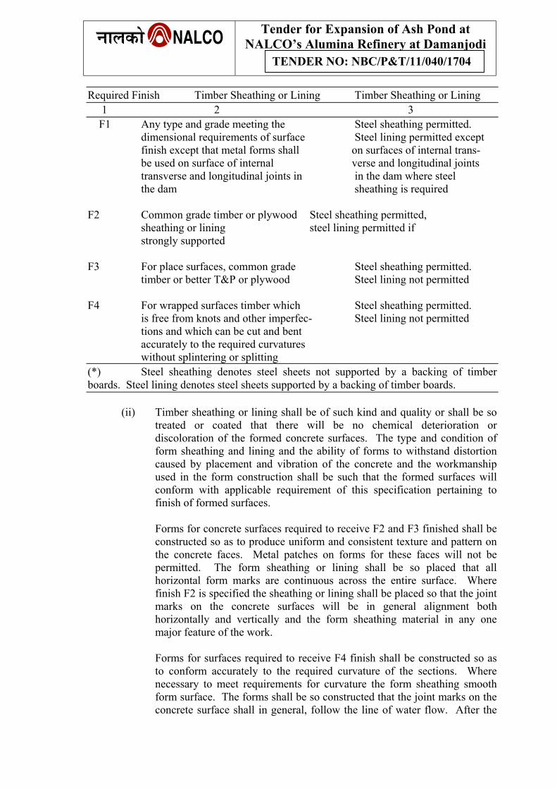
Tender for Expansion of Ash Pond at NALCO’s Alumina Refinery at Damanjodi
TENDER NO: NBC/P&T/11/040/1704
Required Finish Timber Sheathing or Lining Timber Sheathing or Lining 1 2 3 F1 Any type and grade meeting the Steel sheathing permitted. dimensional requirements of surface Steel lining permitted except finish except that metal forms shall on surfaces of internal trans- be used on surface of internal verse and longitudinal joints transverse and longitudinal joints in in the dam where steel the dam sheathing is required F2 Common grade timber or plywood Steel sheathing permitted, sheathing or lining steel lining permitted if strongly supported F3 For place surfaces, common grade Steel sheathing permitted. timber or better T&P or plywood Steel lining not permitted F4 For wrapped surfaces timber which Steel sheathing permitted. is free from knots and other imperfec- Steel lining not permitted tions and which can be cut and bent accurately to the required curvatures without splintering or splitting (*) Steel sheathing denotes steel sheets not supported by a backing of timber boards. Steel lining denotes steel sheets supported by a backing of timber boards.
(ii) Timber sheathing or lining shall be of such kind and quality or shall be so
treated or coated that there will be no chemical deterioration or discoloration of the formed concrete surfaces. The type and condition of form sheathing and lining and the ability of forms to withstand distortion caused by placement and vibration of the concrete and the workmanship used in the form construction shall be such that the formed surfaces will conform with applicable requirement of this specification pertaining to finish of formed surfaces.
Forms for concrete surfaces required to receive F2 and F3 finished shall be
constructed so as to produce uniform and consistent texture and pattern on the concrete faces. Metal patches on forms for these faces will not be permitted. The form sheathing or lining shall be so placed that all horizontal form marks are continuous across the entire surface. Where finish F2 is specified the sheathing or lining shall be placed so that the joint marks on the concrete surfaces will be in general alignment both horizontally and vertically and the form sheathing material in any one major feature of the work.
Forms for surfaces required to receive F4 finish shall be constructed so as
to conform accurately to the required curvature of the sections. Where necessary to meet requirements for curvature the form sheathing smooth form surface. The forms shall be so constructed that the joint marks on the concrete surface shall in general, follow the line of water flow. After the
Tender for Expansion of Ash Pond at NALCO’s Alumina Refinery at Damanjodi
TENDER NO: NBC/P&T/11/040/1704
forms have been constructed, all the nail shall be hidden and any roughness and all angles on the surface of the forms caused by matching the forms material shall be dressed to curvature.
If temperate hard wood is used as a form lining, it shall be continuously
supported with timber of plywood.
(iii) Embedded ties for holding forms shall remain embedded and except where F1 finish is permitted, shall terminate not less than two diameters or twice the minimum dimension of the tie or ten millimeters whichever is greater, in formed faces of the concrete. Where F1 finish is permitted, ties may be cut off flush with formed surface.
The ties shall be constructed so that removal of the ends or end fasteners can be accomplished without causing appreciable spelling at the faces of the concrete. Recesses resulting from removal of the ends of the form ties shall be filled in accordance with the provisions of section of repair of concrete.
3.12.3 Cleaning and treatment of forms:
At the time concrete is placed in the forms, the surface of the forms shall be free from encrustations of mortar, grout or other foreign material. Before concrete is placed, the surfaces of the forms designated to produce F1, F2 and F4 finished shall be oiled with commercial form oil that will effectively prevent sticking and will not stain the concrete surfaces. For timber forms, form oil should consist of pure refined, pale paraffin mineral oil or other approved form of oil. For steel forms, form oil shall consist of refined mineral oil suitably compounded with one or more ingredients, which are appropriate for the purpose.
Care shall be taken to keep form oil out of contract with reinforcement.
3.12.4 Removal of forms:
(i) Except as otherwise provided in this sub-clause of forms shall be provided as soon as the concrete has hardened sufficiently to prevent damage by careful form removal, thus facilitating satisfactory progress with specified curing and earliest practicable repair of surface imperfections.
(ii) Forms on upper slopping faces of concrete, such a forms on the water sides of warped transitions, shall be removed as soon as the concrete has attained sufficient stiffness to prevent sagging. Any needed repairs or treatment required on such slopping surfaces shall be performed at once and be followed immediately by the specified curing.
(iii) In order to avoid excessive stresses in the concrete that might result from
swelling of the forms, timber forms for wall opening shall be loosened as soon as this can be accomplished without damage to the concrete.
(iv) Subject to approval, forms on concrete surface close to excavated rock
surface may be left in place provided that the distance between the concrete
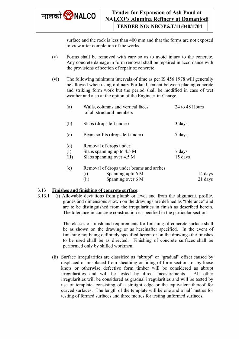
Tender for Expansion of Ash Pond at NALCO’s Alumina Refinery at Damanjodi
TENDER NO: NBC/P&T/11/040/1704
surface and the rock is less than 400 mm and that the forms are not exposed to view after completion of the works.
(v) Forms shall be removed with care so as to avoid injury to the concrete.
Any concrete damage in form removal shall be repaired in accordance with the provisions of section of repair of concrete.
(vi) The following minimum intervals of time as per IS 456 1978 will generally
be allowed when using ordinary Portland cement between placing concrete and striking form work but the period shall be modified in case of wet weather and also at the option of the Engineer-in-Charge.
(a) Walls, columns and vertical faces 24 to 48 Hours of all structural members (b) Slabs (drops left under) 3 days (c) Beam soffits (drops left under) 7 days (d) Removal of drops under: (I) Slabs spanning up to 4.5 M 7 days (II) Slabs spanning over 4.5 M 15 days (e) Removal of drops under beams and arches
(i) Spanning upto 6 M 14 days (ii) Spanning over 6 M 21 days 3.13 Finishes and finishing of concrete surface: 3.13.1 (i) Allowable deviations from plumb or level and from the alignment, profile,
grades and dimensions shown on the drawings are defined as “tolerance” and are to be distinguished from the irregularities in finish as described herein. The tolerance in concrete construction is specified in the particular section.
The classes of finish and requirements for finishing of concrete surface shall be as shown on the drawing or as hereinafter specified. In the event of finishing not being definitely specified herein or on the drawings the finishes to be used shall be as directed. Finishing of concrete surfaces shall be performed only by skilled workmen.
(ii) Surface irregularities are classified as “abrupt” or “gradual” offset caused by
displaced or misplaced from sheathing or lining of form sections or by loose knots or otherwise defective form timber will be considered as abrupt irregularities and will be tested by direct measurements. All other irregularities will be considered as gradual irregularities and will be tested by use of template, consisting of a straight edge or the equivalent thereof for curved surfaces. The length of the template will be one and a half metres for testing of formed surfaces and three metres for testing unformed surfaces.
Tender for Expansion of Ash Pond at NALCO’s Alumina Refinery at Damanjodi
TENDER NO: NBC/P&T/11/040/1704
(iii) The classes of finish for formed concrete surfaces are designated by one of the symbols F1, F2, F3 & F4. Bag rubbing or sand blasting will not be required on formed surfaces. Grinding will not be required on formed surfaces other than that necessary for the repair of surface imperfections. Unless otherwise specified or indicated on the drawings the classes of finish which will apply are as follows:
(a) Finish F1:
This finish applies to surfaces where roughness is not objectionable, such as those upon or against which fill material, masonry or concrete will be placed, the upstream face of the dam that will permanently be underwater or surface that will otherwise be permanently concealed. The surface treatment shall be repaired of defective concrete, correction of surface depressions deeper than 25 mm and filling of tie rod holes. Form sheathing shall not leak mortar when the concrete is vibrated. Forms may be built with a minimum of refinement.
(b) Finish F2:
This finish is required on all permanently exposed surfaces for which other finishes are not specified, such as in outlet works and open spillways, bridges and retaining walls not prominently exposed to public view and in the galleries and adits in the dam, except where F1 finishes are permitted. Forms shall be built in a workmanlike manner to the required dimensions and a alignment, without conspicuous offsets of bulge. Surface irregularities shall not exceed 5 mm for abrupt irregularities and 10 mm for gradual irregularities measured from a 1.5 m template.
(c ) Finish F3:
This finish is designated for surfaces of structures prominently exposed to public view where appearance is of special importance. This shall include parapets, railings and decorative features on the demand on the bridge. To meet the requirements for the F3 finish forms shall be built in a skill full, workmanlike manner, accurately to dimensions. There shall be no visible offsets, bulges or misalignment of the concrete. At construction joints the forms shall be tightly set and securely anchored close to the joint. Surface irregularities shall not exceed 3 mm for abrupt irregularities and 5 mm for gradual irregularities measured from a 1.5 m template.
(d) Finish F4:
This finish is required for formed concrete surfaces at the spillway crest, glacis and bucket and inside sluices where accurate alignment and evenness of surface are essential for prevention of destructive effects of water action. The forms must be strong and held rigidly and accurately to the prescribed alignment. For warped surfaces, the forms shall be built up in section cut to make right, smooth form surfaces after which the form surfaces are dressed and sanded to the required curvature.
When measured as described in this clause, gradual irregularities shall not exceed 5 mm. Abrupt irregularities will not be permitted. The formations of air holes on the surface of the concrete designated to receive finish shall be minimized and where such air holes are found, they shall be repaired in accordance with relevant section.
Tender for Expansion of Ash Pond at NALCO’s Alumina Refinery at Damanjodi
TENDER NO: NBC/P&T/11/040/1704
3.13.2 The classes of finish for unformed concrete surfaces are designated by the symbols U1, U2, U3 & U4. Unless otherwise specified or indicated on the drawings, these classes of finish shall apply as follows:
(i) Finish U1:
This finish applies to unformed surfaces that will be covered by fill material, masonry or concrete or where a scruded surface finish meets the functional requirements. Finish U1 is also used as the first stage of finished for U2 and U3. Finishing operation shall consist of sufficient leveling and screeding to produce even uniform surfaces. Surface irregularities measured as described in this section, shall not exceed 10 mm.
(ii) Finish U2:
This is a floated finish and applies to all out door unformed surfaces not specified to receive finishes U1 or U3. It may be used for such surfaces as of spillways and aprons.
Finish U2 is also used as the second stage of finish for U3. Floating may be performed by use of hand or power driven equipment. Floating shall be started as soon as the screeded surface has stiffened sufficiently to prevent the formation of laitance and shall be the minimum necessary to produce a surface that if free from screed marks and is uniform in texture. If finish U3 is to be applied floating shall be continued until a small amount of mortar without excess water is brought to the surface, so as to permit effective trowel ling. Surface irregularities measured as described in this section shall be tolled down where shown on the drawing or as directed.
(iii)Finish U3:
This is a trowel led finish and may be specified for tops or parapets prominently exposed to view and conduit invert immediately downstream of regulating gates and valves. When the treated surface has hardened sufficiently to prevent excess of fine material from being drawn to the surface, steel trowel ling shall be started.
Steel trowelling shall be performed with firm pressure such as will flatten at the sandy texture of the floated surface and produce a dense uniform surface free from blemishes and trowel marks. Surface irregularities, measured as described in relevant part of this section, shall not exceed 5 mm. Where hard steel trowelled finish is specified, the regular U3 finish shall be trowelled again after the surface has nearly hardened using firm pressure and trowelling until the surface is hard and has a slightly glossy appearance.
(ii) Finish U4:
This is a steel trowelled finish similar to finish U3 except that light surface pitting and light trowel marks such as obtained from the use of machine trowelling or lining machines will be acceptable provided the surface irregularities do not exceed the limits specified for finish U3.
Tender for Expansion of Ash Pond at NALCO’s Alumina Refinery at Damanjodi
TENDER NO: NBC/P&T/11/040/1704
3.13.3 Unformed surfaces which are nominally level shall be sloped for drainage as sloped for drainage as shown on the drawings or as directed. Unless the use of other slopes or level surface is indicated on the drawings, narrow surface such as tops of parapets, tops of walls and kerbs shall be slopped approximately one on per 30 Cm of width, border surface such as roadways, platform and decks, shall be sloped approximately half centimeter per 30 Cm of width.
3.14 Repairs of Concrete: 3.14.1 Repairs of concrete shall be performed by skilled workers and in the presence of an
experienced Engineer. The contractor shall correct all imperfections on the concrete surface as necessary to produce surfaces that conform with the requirements of the section “Finishes and finishing of concrete surfaces” on formed concrete shall be completed as soon as practicable after removal of forms and within 24 hours after removal of forms. Concrete that is damaged from any cause and concrete that is honey combed, fractured or otherwise defective and concrete which because of excessive surface depressions must be excavated and built up to bring up the surface to the prescribed lines, shall be removed and replaced by dry pack mortar or concrete as hereinafter specified. Where bulges and abrupt irregularities protrude outside the limits specified in the section “Finishes & finishing of concrete surfaces”, the protrusions shall be reduced by bush hammering and grinding so that the surfaces are within the specified limits.
3.14.2 Methods of Repairs: For new works four methods are used.
(i) Dry pack method:
This method should be used for holes having a depth nearly equal to or greater than the least surface dimensions, for cone bolt, the bolt and grout insert holes and narrow slots cut for the repair of cracks. Dry pack should not be used for relatively shallow depressions where lateral restraint cannot be obtained for filling in back of considerable lengths of exposed reinforcements nor for filling holes which extend entirely through the wall, beams etc.
(ii) Concrete replacement method:
Concrete replacement should be used when holes extend entirely through the concrete sections, when holes in unreinforced concrete are more than 1000 Sqcm in area and 100 Cm or more in depth and in hole in reinforced concrete are more than 500 Sqcm in area and deeper than the reinforcement steel.
(iii) Mortar replacement method:
This should be used for holes too wide to dry pack and too shallow for concrete replacement, for all comparatively shallow depressions, large and small which extent more deeper than far side of the reinforcement bars nearest the surface.
(iv) Epoxies method:
A thermo setting plastic known as epoxy can be used as a bonding medium wherever long time curing of conventional concrete cannot be assured. Also epoxy mortar of fine sand as well s plain epoxy are suitable for concrete repair work and should be used wherever very thin patches are to be placed for immediate results of the area is
Tender for Expansion of Ash Pond at NALCO’s Alumina Refinery at Damanjodi
TENDER NO: NBC/P&T/11/040/1704
required or where moist curing cannot be effectively accomplished. Preparation for epoxy-bonded repair should in general be identical to that for other concrete repairs except that every effort should be made to provide surfaces, which are thoroughly dry. Drying of the immediate surface for at least 24 hours and warming to temperature between 65o to 80o F are essential for proper application of epoxy bonded repairs. Preparation for the use of epoxy mortar should include thorough cleaning and drying of the areas to be repaired. A wash of dilute 1:4 ratio acids rinsing with clean water and subsequent drying is desirable where feasible. IF acid wash is not feasible, preparation may be accomplished as for other concrete repairs with final clean up being by means of sand blast method followed by air washer jet washing and thorough drying. Epoxy repairs shall be carried out only by trained personnel.
3.14.3 Preparation of concrete for repair:
All concrete of questionable quality should be removed. It is better to remove too much concrete than too little because affected concrete generally continues to disintegrate and while the work is being done it cost but little more to excavate to ample depth. Moistening, cleaning surface drying and complete curing are of utmost importance when making repair, which must be thoroughly bonded, water tight and permanent. Surfaces between trimmed holes should be kept continuously wet for several hours, preferably overnight prior to placing new concrete. Immediately before placement of the filling, the holes should be cleaned so as to leave a surface completely free of chipping dust, dried grout and all other foreign materials. A preliminary washing as soon as the chipping and trimming are completed is desirable to remove loose materials. Final cleaning of the surfaces to which the new concrete is to be bonded should be done by wet sand blasting followed by washing with air water jet for thorough cleaning and drying with an air jet. Care should be taken to remove any loose materials embedded in the surface by chisels during the trimming and to be initiate all shiny spots indicating free surface moistures. Cleaning of steel if necessary should be accomplished by sand blasting. The surface shall be approved by the Engineer-in-Charge.
(i) Dry pack of concrete:
For this method of repair, the holes should be sharp and square at the surface edges but the corners within the holes should be rounded, especially when water tightness is required. The interior surfaces of holes left by cone bolts, she bolts etc., should be roughened to develop an effective bond. Other holes should be under cut slightly in several places around the perimeter. Holes for dry pack should have a minimum depth of 25 mm.
(ii) Concrete replacement: Preparation for this method should be as follows:
(a) Holes should have minimum depth of 100 mm in new concrete and the minimum area of repair should be 500 Sqcm for reinforcement and 1000 Sqcm for unreinforced concrete.
(b) The reinforcement bars should not be left partially embedded; there should be a
clearance of at least 25 mm around each exposed bar.
Tender for Expansion of Ash Pond at NALCO’s Alumina Refinery at Damanjodi
TENDER NO: NBC/P&T/11/040/1704
(c) The top edge of the holes at the face of the structure should be cut to a fairly horizontal line. If the shape of the defect makes it advisable, the top of the cut may be stepped down and continued on a horizontal line. The top of the hole should be cut to 1 to 3 upward slopes from the back towards the face of the wall or a beam. It may be necessary to fill the hole from both sides, in which case the slope of the top of the cut should be modified accordingly.
(d) The bottom and sides of the hole should be cut sharp and approximately square
with the face of the wall. When the hole goes entirely through concrete section spilling or featheredges shall be avoided by having chippers worked from both faces. All interior corners should be rounded to a minimum radius of 25 mm.
(iii) Mortar replacement:
When mortar gun is used with this method, comparatively shallow holes should be flared outwardly at about 1:1 slope to avoid inclusion of rebound. Corners within the holes should be rounded. Shallow imperfections in new concrete may be repaired by mortar replacement if the work is done promptly after removal of the forms and while the concrete is still green for instance when it is considered necessary to repair the peeled areas resulting from surface material sticking to steel forms and surfaces, may be filled using mortar guns without further trimming or cutting. Wherever hard placed mortar replacement is used, edges of chipped out areas should be squared with the surface leaving no featheredges
(iv) Use of dry pack mortar: The surface after preparing should be thoroughly brushed with a stiff mortar or grout barely wet enough to thoroughly wet the surface after which dry pack material should be immediately packed into place before the bonding grout has dried. The mix of bonding grout is to be 1:1 cement and fine sand mixed to a consistency like thick cream. Under no circumstances should be bonding coat be wet enough or applied heavily enough to make the dry pack material more than very slightly rubbery. Dry pack is usually a mix (dry volume or weight) of one part of cement to 1 ½ parts of sand that will pass a No.16 screen. A mortar patch is usually darker than the surrounding concrete unless special precautions are taken to match the colours. Where uniform colour is important white cement may be used in sufficient amount to produce uniform appearance. For packing cone bolt holes a leaner mix of 1:3 ½ will be sufficiently strong and will blend better with the colour of the wall. Only enough water should be used to produce a mortar which when used, will stick together on being moulded into a wall by a slight pressure of hands and will not exclude water but will leave the hands damp. The proper amount of mixing water and proper consistencies are those, which will produce a filling, which is at the point of rubbery when the material is solidly placed. Dry pack material should be placed and packed in layers having a compacted thickness of about 10 mm. The surface of each layer should be scratched to facilitate bonding with next year. One layer may follow another immediately unless appreciable rubberiness develops in which case work on the repair should be delayed to 30 to 40 minutes. Under no circumstances should alternate layers of wet and dry materials be used. Each layer should be solidly
Tender for Expansion of Ash Pond at NALCO’s Alumina Refinery at Damanjodi
TENDER NO: NBC/P&T/11/040/1704
compacted over its entire surface by use of a hard wood stick and hammer. Much of the tamping should be directed at a slight angle and towards the sides of the hole to assure maximum compaction in these areas. The hole should not be over filled and finishing may usually be completed at once by laying the flat side of a hardwood place against the fill and striking at several good blows.
If necessary, a few light strokes with a rag some time later may improve the appearance. Steel finishing tools should not be used and water must not be used to replacement of concrete.
3.14.4 Procedure of replacement of concrete curing of repairs etc.
All procedures for replacement of concrete, mortar replacement, use of epoxies and curing of repairs shall be according to the provisions laid down in Chapter-VII Repair and Maintenance of Concrete Manual, the United States Bureau of Reclamation, Seventh Edition 1963.
3.15 Curing of Concrete: 3.15.1 All concrete shall be cured by water in accordance with the requirement of sub-
clause (3) of this clause or membrane curing in accordance with the requirements of sub-clause (4) of this clause. Concrete surfaces to be painted shall not be cured by membrane curing.
3.15.2 The unformed top surfaces of walls and piers shall moistened by covering with
water-saturated material or by other effective means as soon as the concrete has hardened sufficiently to prevent damage by water. These surfaces and steeply slopping and vertical formed surfaces shall be kept completely and continuously moist, prior to and during form removal, by water applied on the unformed top surfaces and allowed to pass down between the forms and the formed concrete faces. This procedure shall be followed by the specified water curing and membrane curing.
3.15.3 Concrete cured with water shall be kept wet for at least 14 days immediately
following placement of the concrete or until covered with fresh concrete by covering with water saturated material or by a system of perforated pipes, mechanical sprinklers or porous hoses or by any other suitable method, which will keep all the surfaces continuously (not periodically) wet. The period of 14 days specified above shall be increased to 21 days when pozzolana has been used in the concrete as part replacement of cement.
3.15.3.1 (i) Membrane curing shall be by application of a suitable type of white
pigmented curing compound which forms a water retaining membrane on the surfaces of concrete, provided that on concrete surfaces which will be permanently exposed to view clear curing compound may be required. Curing compound shall be applied to the concrete surfaces by spraying on one coat to provide a continuous uniform membrane overall area, with a maximum coverage per gallon as prescribed by the manufacturer according to the roughness of the surface to be covered. If necessary to cover the surface adequately a second coat of curing compound shall be applied by spraying at right angles to the direction at which the first coat was applied. Mortar
Tender for Expansion of Ash Pond at NALCO’s Alumina Refinery at Damanjodi
TENDER NO: NBC/P&T/11/040/1704
encrustations and fins on surfaces for which finish F4 is specified shall be removed prior to application of curing compound. Curing compound shall be applied to all areas of concrete surfaces except that those parts with surface imperfections shall be omitted until repaired.
(ii) When curing compound is to be used on unformed concrete surfaces,
application of the compound shall commence immediately after the finishing operations are completed.
(iii)When curing compound is to be used formed concrete surfaces, the surface
shall be moistened with light spray of water immediately after the forms are removed and shall be kept wet until the surfaces will not absorb more moistures. As soon as the surface film of moisture disappears but while the surface still has a damp appearance, the curing compound shall be applied. There must be ample coverage with the compound at edges, corners and rough spot of formed surfaces. After application of curing compound has been completed and the coating is dry to the tough, any required repair of concrete surface shall be performed. Each repair after being finished shall be moistened and coated with curing compound in accordance with the foregoing requirements.
(iv) Traffic and other construction operations shall be such as to avoid damage to
coatings of curing compound for a period of not less than 28 days after application of the curing compound. Where it is impossible because of construction operations to avoid traffic over surfaces coated with curing compound, the membrane shall be protected by a covering of sand or earth not less than 25 mm thickness or by other effective means. The protective covering shall not be placed until the sealing membrane is completely dry. Any sealing membrane that is damaged or that peels form concrete surfaces within 28 days after application shall be repaired without delay.
(v) Curing compound if used, shall be of approved quality.
3.16 Cooling of Concrete:
Heat released during hydration of cement when large masses of concrete are being produced poses two different problems viz., (1) the thermal stability of concrete and (2) the tracking of concrete. The thermal stability is necessary for normal behaviour of the structure. So suitable cooling system is to be adopted in the dam concreting in order to rapidly achieve thermal stability.
In order to control thermal instability arising out the heat of hydration the placement temperature of concrete should be adopted as directed by Enginer-in-Charge.
3.17 Tolerance for concrete construction: 3.17.1 General:
(i) Permissible surface irregularities for the various classes of concrete surface finish specified in the relevant portion of the section on “finishes and finishing of concrete surface” are defined as finishes and are to be
Tender for Expansion of Ash Pond at NALCO’s Alumina Refinery at Damanjodi
TENDER NO: NBC/P&T/11/040/1704
distinguished for “Tolerances” as described in this section. Deviations from the established lines, grades and dimensions will be permitted to the extent set-forth in this clause, provided that lesser tolerances than that tolerance set-forth in this clause may be prescribed at site if such tolerances are considered to impair the structural action or operational action or operational function of the structure.
(ii) Where tolerances are not stated in the specifications or drawings for any individual’s structure or feature thereof, permissible deviations will be interpreted in conformity with the provisions of this clause.
(iii) Concrete work that exceeds the tolerance limits specified in this section shall be either remedied satisfactorily or removed.
3.17.2 Mass concrete in dams and appurtenant works:
The following tolerances shall apply for concrete in dams and other larger mass concrete structures:
(i) (a) Variation of the constructed In 6 metres 12 mm
linear outlines from established In 12 metres 20 mm position in plan
(b) Variations for dimensions In 24 metres 30 mm to individual structural or more features from established positions In buried Twice the construction above amount
(ii) (a) Variations from the plumb In 3 metres 12 mm from the specified batter In 12 metres 30 mm or from the curved surfaces or more of all structures including In buried Twice the the lines and surfaces of construction above
walls and vertical joints amount (iii) Variations in cross sectional Minus 6 mm dimensions of columns, beams, buttresses, piers and similar Plus 12 mm members and variation in the thickness of slabs walls and similar members (iv) Variation from plumb and Not greater level for sills and side walls than a rate for radial gates and similar of 3 mm in water tight joints metres
3.17.3 Placing reinforcement bars:
The following tolerance shall apply for placing of reinforcement bars:
Tender for Expansion of Ash Pond at NALCO’s Alumina Refinery at Damanjodi
TENDER NO: NBC/P&T/11/040/1704
(i) Variation of protective covering With 60 mm cover & over 6 mm With 75 mm cover & over 12 mm
(ii) Variation from indicated spacing Provided that number of bars required by spacing is not varied: 26 mm
3.18 Measurement & Payment: 3.18.1 General:
The prices entered in the schedule for the incorporation of the various classes of concrete, plain and reinforced required by this section shall be all inclusive consisting full compensation for mobilizing, demobilizing and supplying all equipment, forms, materials, curing, labour, supervision and all incidental work except for any item specifically exempted there from and for which, in addition a specific payment item has been included in the schedule.
3.18.2 Except as otherwise expressly provided for in the specifications, measurement of
concrete for payment shall be made on the basis of the volume of concrete calculated as being contained within the concrete outlines shown on the relevant drawings. No measurements shall be made for the concrete backfill beyond the minimum lines of excavation shown on the drawings except where such payment is specifically authorized. Measurement of concrete shall be made after deducting the volume of all recesses, passageways, chambers, opening cavities and depression embedded pipes and metal works but without deductions for round or beveled edges or space occupied by electrical conduits and reinforcement.
3.18.3 Concrete in spillway bridge, side walks, kerbs and parapets in full length of the
masonry dam and block cuts etc., shall be measured on the basis of volume of concrete calculated as being contained within the concrete outlines shown on the relevant drawings.
3.18.4 Payment for the various classes of concrete shall be made on the basis of unit price
per cubic metre entered in respect of items in the schedule. 4.0 Reinforcement: 4.1 General: 4.1.1 The contractor shall furnish, cut, bend and place steel reinforcement including rods of mild steel and tor-steel as indicated in drawings or as directed by the Engineer-in-Charge. 4.1.2 All steel used for reinforcement shall be clean, free from oil, grease, paints, dust,
mortar, scales, kinks, rust or any rolling defects or ends other than those required as per drawings or directions of the Engineer-in-Charge.
4.2 Quality of reinforcement: 4.2.1 Reinforcement shall be any of the following:
(i) Mild steel and high tensile steel bars and hard drawn steel wire conforming to IS: 432 1960 as revised from time to time.
Tender for Expansion of Ash Pond at NALCO’s Alumina Refinery at Damanjodi
TENDER NO: NBC/P&T/11/040/1704
(ii) Structural steel sections conforming to IS: 226 – 1955 as revised from time to time.
(iii) Cold twisted steel bars complying with the requirement of IS:1786-1966 as
amended from time to time.
(iv) Such other reinforcement as may be proved suitable having regard to the yield point stress ductility, ultimate resistance to tension and other essential properties of the completed reinforcement as produced in readiness for reinforced concrete.
4.2.2 Bar stock shall be periodically tested for quality, from time to time during as
progress of work and when there is doubt that bar stock may not conform to the requirements of the specifications.
Bar stock not meeting the requirement of the specifications shall not be used in the work.
4.3 Cutting and bending: 4.3.1 Reinforcement bars shall be of the size prescribed and shall be cut to the lengths,
bent to the shape and fixed in position shown on the drawings or as directed by the Engineer-in-Charge and shall conform to IS: 2502-1963 as revised from time to time.
4.3.2 Deformed bars shall not be resent after being bent and straightened unless initially
bending and subsequent straightening and bending are carried out under proper approved supervision.
4.3.3 Reinforcement bars shall be bent cold. Bars shall not be cooled by quenching.
Bars shall not be straightened or bent in a manner that will injure or weaken the material.
4.4 Jointing and Splicing: 4.4.1 Joints or splices in reinforcement bars shall be made at the position shown on the
drawings. Additional joints or splices may be permitted at positions other than those shown on the drawings provided that the position of joints and splices in adjacent bars are staggered and are placed as approved.
4.4.2 Reinforcement bars 28 mm in diameters and larger may be connected by butt
welding provided that lapped splices will be permitted if found to be more practical than butt welding and if lapping does not encroach on cover limitations or hinder concrete or reinforcement placing.
4.4.3 Reinforcement bars 25 mm in diameter and less may be either lapped or butt-
welded, whichever is the most practicable. 4.4.4 Deformed bars shall not be lap welded at splices except where lap welding is
shown on the drawings or otherwise specifically approved.
Tender for Expansion of Ash Pond at NALCO’s Alumina Refinery at Damanjodi
TENDER NO: NBC/P&T/11/040/1704
4.4.5 Butt-welding of reinforcement bars shall be performed under cover from the weather and may be performed either by the gas pressure or flash pressure welding processor by the electric are methods. The following requirements shall apply for all welding of reinforcement bars including butt-welding and the preparation of welded reinforcement mats.
(i) The ends of the bars to be butt-welded by gas pressure of flash pressure. Welding
shall be squared off by an abrasive disc cutter. Any accumulation of dirt or oxide film formed after the cutting operation shall be removed by sand blasting or buffing prior to welding. Ends of bars to be joined by flash pressure welding shall be cleaned of all rust and projections on the end faces and for a distance of about 15 Cm from the ends, if necessary to prevent arching. Care shall be taken in aligning and separating the ends of the bars to be joined by arc welding and the ends of the bars shall be batched accurately and shall be retained firmly in position during the welding operations. For pressure welding the bars shall be accurately held in position with the prescribed pressure applied prior to heating and during heating and welding
(ii) Where bars are to be joined by electric arc welding, the weld metal shall be deposited in successive layers and each layer shall be thoroughly cleaned before the subsequent layer is deposited.
(iii) All structural welds shall have complete fusion and freedom from imperfections. Defective pressure welded joints shall be separated by flame cutting and re-welded.
Defective arc welds shall be chipped to sound metal and resulting cavities shall be
filled in the same manner as the original grooves were filled or the bars shall be flame cut and re-welded.
(iv) Tack welding of reinforcement bars for fixing bars in place or for preparation of
mats shall be carried out by competent operators using approved techniques. The work shall be so performed that there are no sharp discontinuities or loss on cross section in the joined bars at the or adjacent to the weld.
(v) Only operators skilled in the type of welding procedures used for the welding or
reinforcement bars shall be used for work. Before being permitted to weld bars on the job, each operator shall make four satisfactory test welds of the bars using the same bar material, end preparation, pressure, heating and upsetting as will b used for the actual reinforcement. The test bars shall not be less than 45 Cm long before welding. The bars when tested shall show a breaking strength of the metal in the bars. For the welding process and the operator to qualify all test welds must meet this requirement, the operator may be permitted to weld an additional set of bars and if these met the requirement, the process and the operator will be qualified.
(vi) Welding materials and welding procedures and the workmanship of welding operators will be subject to inspection and approval at all times during the progress of the work.
4.4.6 The position and dimension of lapped splices will normally be shown on the
reinforcement drawing where splice are required for the work, the following
Tender for Expansion of Ash Pond at NALCO’s Alumina Refinery at Damanjodi
TENDER NO: NBC/P&T/11/040/1704
minimum overlap of spliced bars shall be used for the various sizes and grades shown. Hooks will not normally be prescribed for splices in structural grade deformed bars.
LAPPED SPLICES Diameter of bars in mm
Grade of bar Minimum length of overlap in strength splices
For S-120 (M-150 Concrete
S-160 (M
8 M S Rounds 28 Cm 21 Cm 10 M S Rounds 47 Cm 35 Cm 12 Deformed ribbed bars 66 Cm 49 Cm 16 Deformed ribbed bars 88 Cm 65 Cm 20 Deformed ribbed bars 110 Cm 82 Cm 22 Deformed ribbed bars 110 Cm 83 Cm 25 Deformed ribbed bars 125 Cm 94 Cm 32 Deformed ribbed bars 160 Cm 120 Cm 36 Deformed ribbed bars 180 Cm 135 Cm 40 Deformed ribbed bars 200 Cm 150 Cm
4.4.7 Binding wire used shall be of soft annealed steel of 16 SWG and shall have an
ultimate strength of not less than 5600 Kgs per Sqcm and an yield point of not les than 3850 Kg per Sqcm.
4.5 Measurement and Payment: 4.5.1 The prices entered in the schedule for the work required by this section shall be all
inclusive constituting full compensation for mobilizing, demobilizing and supplying all equipment, material, labour, supervision and all incidental work except for any item specifically exempted there from and for which in addition a specific payment item has been included in the schedule.
4.5.2 Measurement of steel reinforcement shall be made for the weight of the steel
reinforcement actually placed in position and only to the extent shown in the approved drawings and will include all laps and hooks as directed by the Engineer-in-Charge if now shown in the drawing. The rate shall include the cost of supplying binding wire, labour and making lap joints, tack welding, welded joints, ties and metal supports if any, of hauling, storing, sorting, cutting, bending, cleaning, placing and securing and maintaining in position all reinforcement bars as shown on the drawings or as directed. No payment shall be made on account of the steel bars. Steel used for supports, spaces, ties, pins etc., will not be measured for payment. The weight as specified by the manufacturer’s sectional tables shall be taken as standard for purposed of computing total weight of steel used as reinforcement.
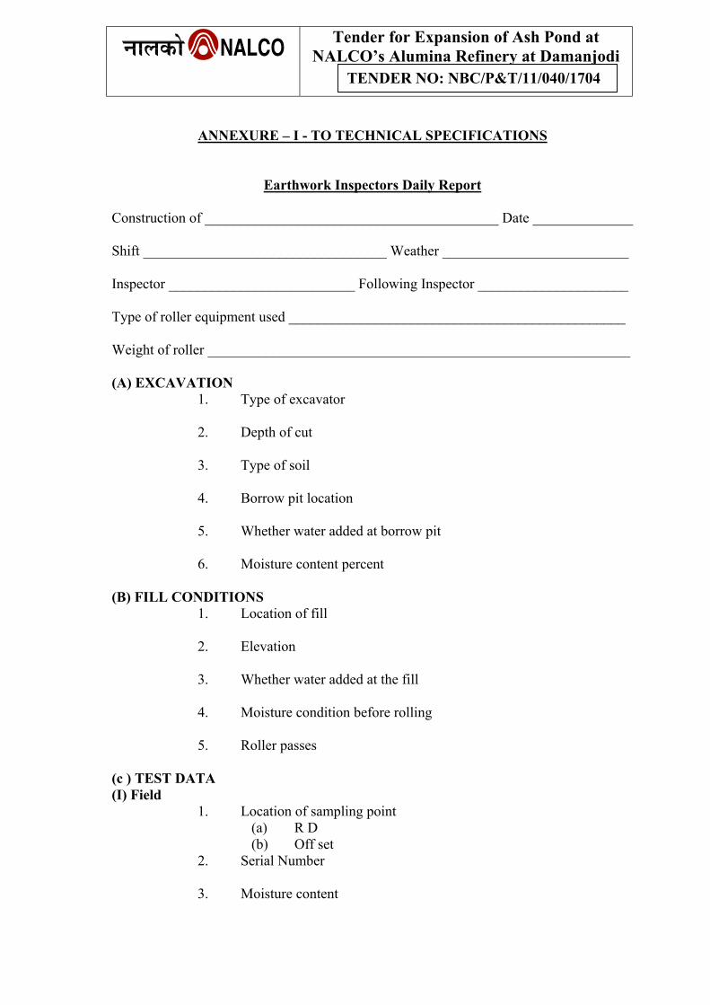
Tender for Expansion of Ash Pond at NALCO’s Alumina Refinery at Damanjodi
TENDER NO: NBC/P&T/11/040/1704
ANNEXURE – I - TO TECHNICAL SPECIFICATIONS
Earthwork Inspectors Daily Report Construction of _________________________________________ Date ______________ Shift __________________________________ Weather __________________________ Inspector __________________________ Following Inspector _____________________ Type of roller equipment used _______________________________________________ Weight of roller ___________________________________________________________ (A) EXCAVATION
1. Type of excavator 2. Depth of cut
3. Type of soil
4. Borrow pit location
5. Whether water added at borrow pit
6. Moisture content percent
(B) FILL CONDITIONS
1. Location of fill 2. Elevation
3. Whether water added at the fill
4. Moisture condition before rolling
5. Roller passes
(c ) TEST DATA (I) Field
1. Location of sampling point (a) R D (b) Off set
2. Serial Number 3. Moisture content
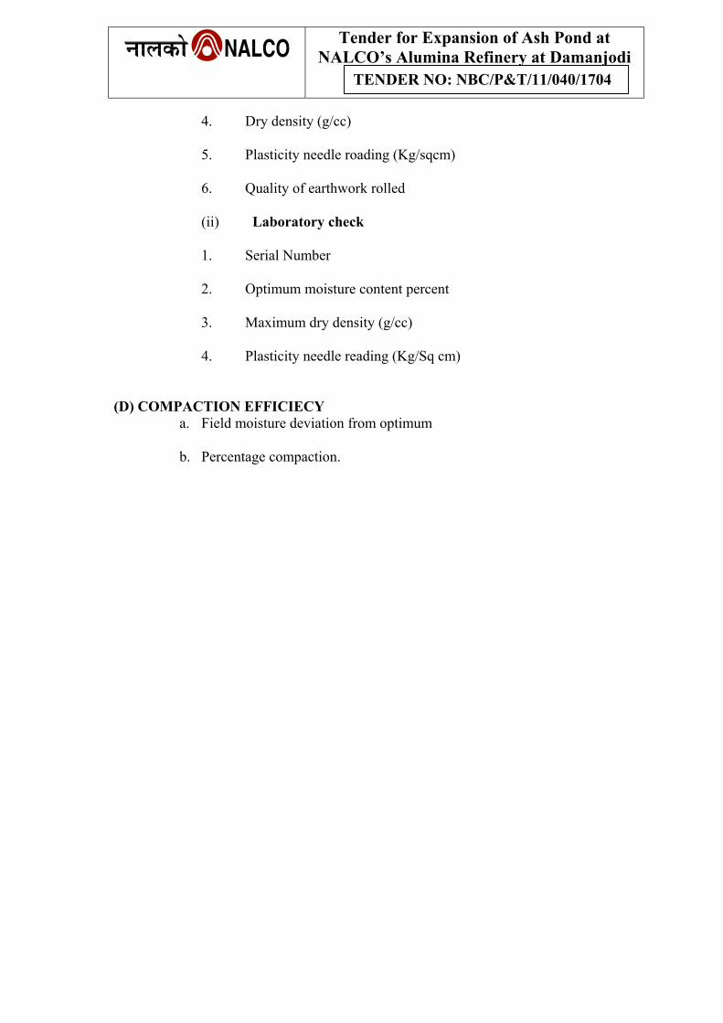
Tender for Expansion of Ash Pond at NALCO’s Alumina Refinery at Damanjodi
TENDER NO: NBC/P&T/11/040/1704
4. Dry density (g/cc)
5. Plasticity needle roading (Kg/sqcm)
6. Quality of earthwork rolled
(ii) Laboratory check 1. Serial Number 2. Optimum moisture content percent
3. Maximum dry density (g/cc)
4. Plasticity needle reading (Kg/Sq cm)
(D) COMPACTION EFFICIECY
a. Field moisture deviation from optimum
b. Percentage compaction.
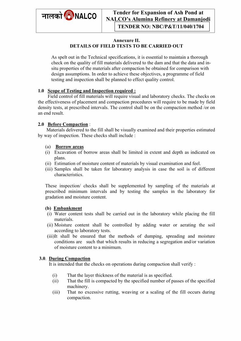
Tender for Expansion of Ash Pond at NALCO’s Alumina Refinery at Damanjodi
TENDER NO: NBC/P&T/11/040/1704
Annexure II. DETAILS OF FIELD TESTS TO BE CARRIED OUT
As spelt out in the Technical specifications, it is essential to maintain a thorough check on the quality of fill materials delivered to the dam and that the data and in-situ properties of the materials after compaction be obtained for comparison with design assumptions. In order to achieve these objectives, a programme of field testing and inspection shall be planned to effect quality control.
1.0 Scope of Testing and Inspection required : Field control of fill materials will require visual and laboratory checks. The checks on the effectiveness of placement and compaction procedures will require to be made by field density tests, at prescribed intervals. The control shall be on the compaction method /or on an end result.
2.0 Before Compaction : Materials delivered to the fill shall be visually examined and their properties estimated by way of inspection. These checks shall include : (a) Borrow areas
(i) Excavation of borrow areas shall be limited in extent and depth as indicated on plans.
(ii) Estimation of moisture content of materials by visual examination and feel. (iii) Samples shall be taken for laboratory analysis in case the soil is of different
characteristics.
These inspection/ checks shall be supplemented by sampling of the materials at prescribed minimum intervals and by testing the samples in the laboratory for gradation and moisture content.
(b) Embankment
(i) Water content tests shall be carried out in the laboratory while placing the fill materials.
(ii) Moisture content shall be controlled by adding water or aerating the soil according to laboratory tests.
(iii)It shall be ensured that the methods of dumping, spreading and moisture conditions are such that which results in reducing a segregation and/or variation of moisture content to a minimum.
3.0. During Compaction It is intended that the checks on operations during compaction shall verify :
(i) That the layer thickness of the material is as specified. (ii) That the fill is compacted by the specified number of passes of the specified
machinery. (iii) That no excessive rutting, weaving or a scaling of the fill occurs during
compaction.
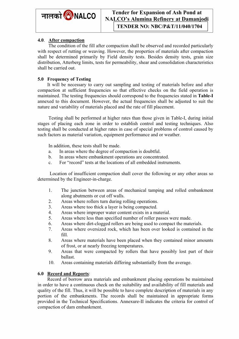
Tender for Expansion of Ash Pond at NALCO’s Alumina Refinery at Damanjodi
TENDER NO: NBC/P&T/11/040/1704
4.0. After compaction The condition of the fill after compaction shall be observed and recorded particularly with respect of rutting or weaving. However, the properties of materials after compaction shall be determined primarily by Field density tests. Besides density tests, grain size distribution, Atterberg limits, tests for permeability, shear and consolidation characteristics shall be carried out.
5.0 Frequency of Testing It will be necessary to carry out sampling and testing of materials before and after compaction at sufficient frequencies so that effective checks on the field operation is maintained. The testing frequencies should correspond to the frequencies stated in Table-I annexed to this document. However, the actual frequencies shall be adjusted to suit the nature and variability of materials placed and the rate of fill placement.
Testing shall be performed at higher rates than those given in Table-I, during initial stages of placing each zone in order to establish control and testing techniques. Also testing shall be conducted at higher rates in case of special problems of control caused by such factors as material variation, equipment performance and or weather.
In addition, these tests shall be made.
a. In areas where the degree of compaction is doubtful. b. In areas where embankment operations are concentrated. c. For “record” tests at the locations of all embedded instruments.
Location of insufficient compaction shall cover the following or any other areas so determined by the Engineer-in-charge.
1. The junction between areas of mechanical tamping and rolled embankment
along abutments or cut off walls. 2. Areas where rollers turn during rolling operations. 3. Areas where too thick a layer is being compacted. 4. Areas where improper water content exists in a material. 5. Areas where less than specified number of roller passes were made. 6. Areas where dirt-clogged rollers are being used to compact the materials. 7. Areas where oversized rock, which has been over looked is contained in the
fill. 8. Areas where materials have been placed when they contained minor amounts
of frost, or at nearly freezing temperatures. 9. Areas that were compacted by rollers that have possibly lost part of their
ballast. 10. Areas containing materials differing substantially from the average.
6.0 Record and Reports: Record of borrow area materials and embankment placing operations be maintained in order to have a continuous check on the suitability and availability of fill materials and quality of the fill. Thus, it will be possible to have complete description of materials in any portion of the embankments. The records shall be maintained in appropriate forms provided in the Technical Specifications. Annexure-II indicates the criteria for control of compaction of dam embankment.
Tender for Expansion of Ash Pond at NALCO’s Alumina Refinery at Damanjodi
TENDER NO: NBC/P&T/11/040/1704
7.0 Field Test Data Records of field test data results should be presented in the form of statistical analysis sheets and summary sheets in order to provide control required for enforcement of statistical requirements of the specifications.
The test data summary sheets and inspection reports should be used to form the basis of construction control report, which should be prepared and issued from the site at fortnightly intervals during construction season. The report would contain narrative accounts of the progress and problems of fill construction, statistical analysis of test data and photographs of the fill operations. As a guidance please refer to USBR Earth Manual Ch.-III Para 71 control criteria.
8.0 Embankment Test Section Placement of compaction methods specified will have to be verified by the test embankment section to be built prior to starting of fill operations or at an early stage of Dam construction. The initial stage of dam construction itself could be made to serve the purpose of test embankments. The test sections referred herein shall be used to establish:
(a) Layer thickness of fill materials. (b) Optimum practicable moisture content. (c) Number of passes of sheep foot roller, or weight of vibratory rollers vis-à-vis
of passes for effective compaction. When an appreciable change in material occurs, additional test sections shall be made during construction. The procedure for construction of test embankment section is as follows:
(a) Select a location on the embankment where uninterrupted placing operations
are being performed. This area 15m. by 30m (about 50ft. x 100 ft.) should be carefully marked and referenced so that its limits will be easily recognized. In order to expedite the determination of moisture content to be used, more than one test section may be established on the embankment at the time.
(b) During construction of the test section, which will most probably continue for
several shifts, a complete record of the procedure should be kept. This record should include the number of layers placed, the spread thickness of each layer, the moisture content, at which the materials were rolled, the designation (No.1, No.2 etc.) of the rollers used, the condition of the rollers (clean or dirty), the action of the materials being rolled (such is of wavy under the rollers, the amount of penetration of the roller teeth after different number of roller trips etc.) and the borrow pit location from which the materials came.
(c) Check the roller to make certain that they meet all the requirements of
specifications.
(d) Determine the required spread thickness of layer that will compact to the specified thickness after rolling specified number of times and maintain this thickness as long as a number of roller passes is kept the same.
Tender for Expansion of Ash Pond at NALCO’s Alumina Refinery at Damanjodi
TENDER NO: NBC/P&T/11/040/1704
(e) Using the available data from borrow pit investigations of the materials to be
used in the test section the optimum moisture content as determined by laboratory tests will be known and 3 percent less than optimum moisture content (OMC)should be used in the first 3 or 4 layers rolled.
(f) After 3 or 4 layers have been placed at 3 percent less than the laboratory
optimum moisture content, field density test should be made throughout the section. These tests should be made for at least each 93 Sq. Meters (1000 Sq. feet) of test section area, and should be so distributed over the area that they will detect the effects of different compaction conditions encountered during construction. For example, if the section is located near an abutment, certain parts of the areas will receive more compaction from track travel than others, hence some tests should be made in the portion compacted only by the rollers and so reported.
(g) The next step is to compact another 3 or 4 layers at the moisture content
slightly higher (1 percent or 2 percent) than the moisture content previously used, maintaining the same rolled thickness of layer and number of roller passes, as above. Field density tests are again made over the test section.
(h) If the resulting field dry densities (of material passing the No.4 sieve) from (g)
above show an increase with increase of moisture, again by another 1 percent or 2 percent, repeat the test. If an increase in moisture results in a decrease in field dry density then place the next layers slightly dry of the original moisture content used and repeat the test. This procedure is nothing more than developing on the embankment a moisture density relation or compaction curve for a certain roller, thickness of layer, and a given number of roller trips. If special studies during investigation have indicated that the material being tested should be placed within certain moisture limits, or if the moisture limits to be used have been specified, the procedure outlined above should include tests at these moisture contents or at moisture contents both greater and smaller than the specified limits.
(i) The roller compaction curve is now compared with the standard laboratory
compaction curve. If the field density of materials passing the No.4 sieve (from the roller curve) is greater than the standard compaction density at the specified moisture content, the test section should be continued decreasing the number of roller trips while maintaining the specific desirable moisture content until the most economical compactive effort is determined. When the roller trips are decreased, the required spread thickness of layer that will compact to the specified thickness of compacted material should be reckoned.
(j) All works connected with the embankment test section will be done by the
contractors under the supervision and direction of Engineer-in-Charge. No separate payments shall be made for this work.
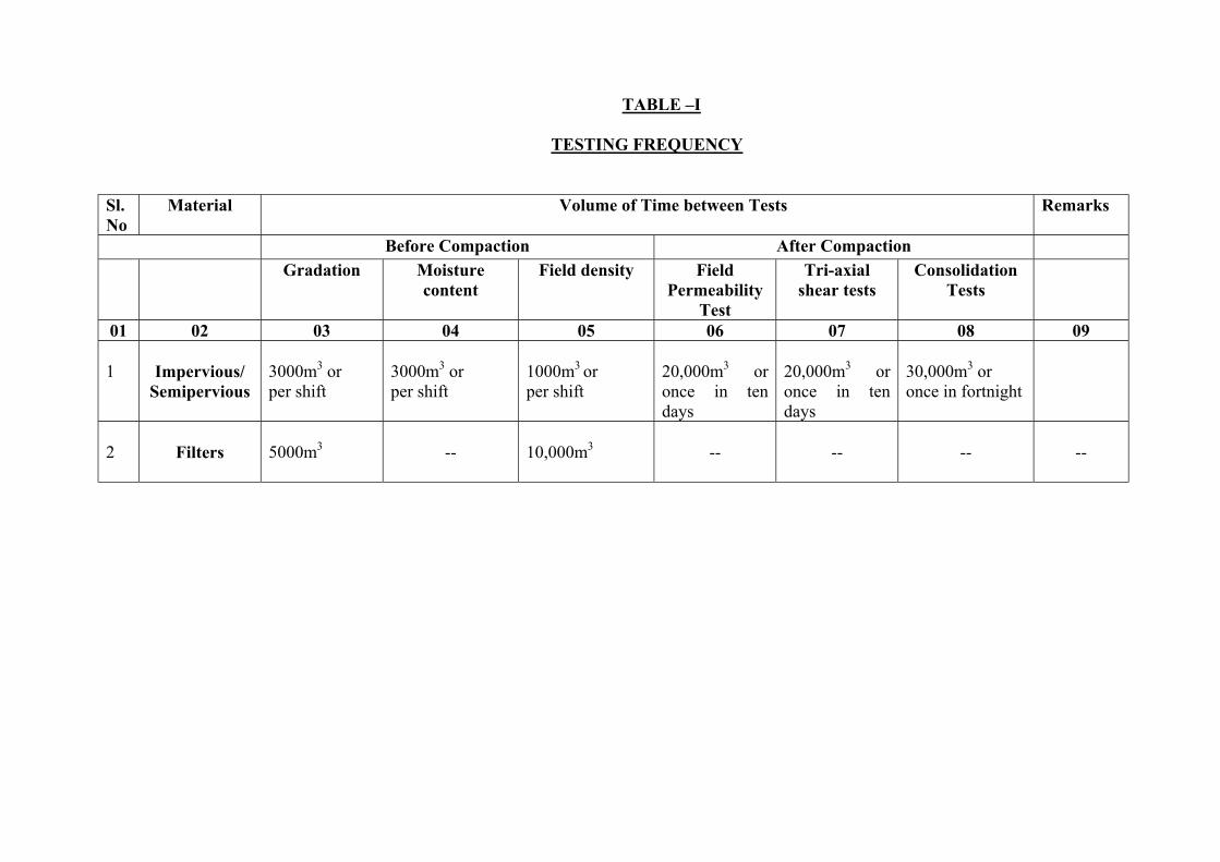
TABLE –I
TESTING FREQUENCY
Sl. No
Material Volume of Time between Tests Remarks
Before Compaction After Compaction Field density Gradation Moisture
content Field
Permeability Test
Tri-axial shear tests
Consolidation Tests
01 02 03 04 05 06 07 08 09 1
Impervious/
Semipervious
3000m3 or per shift
3000m3 or per shift
1000m3 or per shift
20,000m3 or once in ten days
20,000m3 or once in ten days
30,000m3 or once in fortnight
2
Filters
5000m3
--
10,000m3
--
--
--
--
TENDER
FOR
EXPANSION OF ASH POND AT NALCO’s ALUMINA
REFINERY AT DAMANJODI
PREAMBLE TO BILL OF QUANTITIES & SCHEDULE OF
RATE

Preamble to BOQ and Schedule of Quantities
i. The BOQ shall be read with all other sections of this tender document.
ii. The tenderer is deemed to have studied the drawings, specifications and details of work to be done within the specifications and the time schedule enclosed and to have visited the sites and acquainted himself of the conditions prevailing at site.
iii. The quantities shown against the various items are only approximate and may
vary to any extent individually subject to Cl. No.60 of General Conditions of Contract and Cl.12 of the Special Conditions Contract.
iv. All the items of work mentioned in the BOQ and covered by this contract shall be
carried out as per the drawings (Working drawings will be issued at the time of execution), specifications and directions of Engineer-in-Charge and the rates quoted shall include all labour, materials, transportation, handling, duties, octroi, wastages, tools and plants, testing, if any, with contractor's testing appliances etc., required to complete the job in all respects. The rates quoted shall also be deemed to include mobilizing, demobilizing, supplying all equipment, supervision and other incidental works.
v. NALCO reserves the right to cancel the order for any item or group of work or
split the work between two or more contractors, if necessary. Such a step shall not constitute a breach of the contract and the quoted rates shall hold good on such eventualities.
vi. The quoted rates shall take into account the following factors :
6.1 No separate payment shall be made for bailing out / dewatering, wet excavation,
removal of bushes, trees, picking of roots, leveling, making of benching on existing slope of the dam body for proper bonding/ key as per drawing in every layers, disposal of unserviceable excavated materials as directed by Engineer - in - Charge for any leads and lifts for earth work.
6.2 Excavation Stripping for Earth Dam: Payments for this item of work will be made on the basis of actual work executed in m3 which will include excavation, dressing, disposal of excavated material including all leads and lifts. Before starting the work, a block plan of levels of the existing ground shall be prepared by taking levels at every 15M interval or closer, if necessary and normal to the axis of the dam up to a sufficient distance beyond the limits of excavation at 5M interval. Quantities will be computed on the basis of final levels taken at the same locations. No separate payment shall be made towards establishing B.M., reference lines and check profiles as the same is supposed to be included in various items of work.
6.3 Formation of Dam Embankment: Payment for these items of work shall be made
on the basis of cross section method. Initial cross section shall be taken after completion of excavation of cut off trench. Final cross sections shall be taken at 15M interval or closer, if necessary. The gross quantity of impervious core including that of cut off trench shall be based on these cross sections, which shall be restricted to finally approved typical section of the earthen dam. No payment will be made for making the benching or key for proper bonding with existing slope of old dam & new earth filling work as per the specification shown in drawings. The same should be included in the rate of earthwork in embankment filling.
6.4 Graded Sand and Gravel for Filter: Payment for this item of work shall be made in
m3, measurements shall be taken by measuring independently surface area of the slope and multiplying the same by thickness of various layers of filters. The rate shall include all leads and lifts of material, watering and compaction of filter materials. The rock toe portion (if envisaged) shall be measured separately from section shown in drawing and paid on running metre basis. Sand used for the work shall be brought from Nawarangpur, which is 120km away from Damanjodi.
6.5 Stone Pitching (Rip-rap): Payment for this item of work shall be made in m3. For
this purpose, surface area of slopes shall be measured independently. Payments shall be inclusive of all leads and lifts of various materials.
6.6 Rock fill/Rock toe: Payment for this item of work shall be made in m3. For this purpose, cross sectional area shall be measured independently at regular intervals and average area will be multiplied with interval for computation of quantity. Payments shall be inclusive of all leads and lifts of various materials.
6.7 Turfing with pad grass:- Payment for this item of work shall be made in m2. For this
purpose, surface area of slopes shall be measured as per actuals. Payments shall be inclusive of collection of 50 mm average thick approved grass pad and placing the same in slope all leads and lifts along with various materials like cow dung or manure and good quality of clay/soil mixed with cow dung ( 1 part of cow dung : 8 part of approved clay/ soil and laid in 100 mm average thick as per specification) .The turfing will maintained for one year with watering, guarding & maintaining the grass for one year after completion of contract as per specification, no extra payment will be made for this account.
6.8 Precast PCC Kerb Stones: Precast P.C.C. Kerb stones of specified dimensions in
BOQ with all material, shuttering, curing etc., shall be paid on each number supplied and fixed at site.
6.9 Approach Road for Transportation of borrow Earth: All approach roads for the
execution and completion of total works (raising of dam height & construction of new dam including allied works and bringing material/earth from borrow area) shall be responsibility of contractor at his/their own cost and no extra payment shall be entertained in this regard. The contractor’s rates are deemed to be including all enabling works and approach road. For alignment of approach road the contractor has to take approval of Engineer in charge.
6.10 The following leads shown against each Dam shall be taken into consideration
while quoting the rates. The quantity shown in B.O.Q against different leads are purely tentative. The lead has to decide before starting of the earthwork by Engineer-In-Charge considering the availability of required earth in different borrow areas.
7.0 WBM Roads: The payment for this item of work shall be made on Sqm basis.
The measurement for finished surface of work shall be made accurately as per
the work actually done but limited to the extent shown in the approved drawings. The contractors shall be required to carry out the works as per specifications and as per direction of Engineer-in-Charge. The rate shall be inclusive of compensation for mobilizing, demobilizing, supplying all equipment, material and other incidental works.
8.0 Payments of running bills for earth filling works shall be made on the basis of:
(a) For 50% of quantities given in schedule of quantities @ 90% of tendered rate.
(b) In excess of 50 % of quantities given in schedule of quantities @ 95% of tendered rate.
(c) Payment for final bill shall be made at full tendered rate. For the actual quantities executed and after fulfilling all the contractual obligations as required by the contractor. Rates shall be inclusive of providing all construction material and construction of all haul roads (other than those maintained by NALCO) and ramps, lighting of work area and embankment and laying materials including all leads and lifts etc.,
Note: (a) All the sand for construction purpose should be from the river at Nawrangpur (120km away from Damanjodi). The source of the quarry has to be finalized in consultation with Engineer-In-charge for required specification jointly before collection. (b) A list of minimum quality control equipments required for the work is enclosed and the party may be provided the actual deployment of the equipments & experienced staff to be deployed for the work. (c) Necessary permission may be accorded from the competent authority for blasting in garland drains. Blasting shall be done by licensed agency with all necessary compliances required for blasting.