special access connections to the at&t network · this technical reference is published by...
TRANSCRIPT

TR 41458
TECHNICAL REFERENCE
Special Access Connections
To The
AT&T Network
OCTOBER 1996

TECHNICAL REFERENCE
Special Access Connections
To The
AT&T Network
October 1996
AT&T, 1996. Printed In U.S.A.
NOTICE
This Technical Reference is published by AT&T as a guide for the designers, manufacturers, consultantsand suppliers of equipment which would meet the described interface. AT&T reserves the right to revisethis Technical Reference for any reason, including, but not limited to, conformity with standardspromulgated by ANSI, EIA, ITU-T, IS0, or similar agencies, use of new advances in the state of technicalarts, or to reflect changes in the requirements of communications systems or equipment. Any liabilityarising from use of this technical reference is disclaimed. In addition, AT&T makes no claims andrepresentations and assumes no responsibilities beyond those set fourth in the applicable tariffs.
The provision of planned network capabilities as described in this document requires certain businessdecisions and regulatory approvals. Note that, as of the date of publication of this document, many of thesebusiness decisions may not have been made nor regulatory approval received or requested.
No part of this publication may be reproduced or distributed in any form or by any means without the priorwritten permission of AT&T.
If further information is required, please contact:
Switched Services Interfaces GroupAT&T101 Crawfords Corner RoadRoom 3J-507P.O. Box 3030Holmdel, NJ 07733-3030
To order copies of this document
Call:AT&T Customer Information CenterUSA 800-432-6600EUROPE +1-317-322-6416FAR EAST +1-317-322-6389AMERICAS/MID EAST/AFRICA +1-317-322-6646
Write:AT&T Customer Information Center2855 North Franklin RoadP.O. Box 19901Indianapolis, IN 46219
You may request to be placed on standing order to receive updates automatically.
For more information about AT&T documents see: CATALOG OF COMMUNICATIONS TECHNICALPUBLICATIONS, Publication Number 10000.

Special Access Connections
To The
AT&T Network
Contents
Part I: General Information
Part 11: Special Access Interconnection To The AT&T Point Of Termination
Part 111: CPE Guidelines

Part I - General Information
i
Special Access Connections
To The
AT&T Network
Part I
General Information

Part I - General Information
ii
CONTENTS
1. SCOPE................................................................................................................................................... 1
2. CHANGES SINCE LAST ISSUE......................................................................................................... 1
3. ORGANIZATLON OF THIS DOCUMENT........................................................................................ 1
4. SERVICES............................................................................................................................................. 2
4.1 SOFTWARE DEFINED NETWORK (SDN) AND SOFTWARE DEFINED DATA NETWORK (SDDN)...................... 34.1.1 Special Features............................................................................................................................. 44.1.2 Dialing Plans.................................................................................................................................. 54.1.3 SDDN Access Options..................................................................................................................... 54.1.4 SDDN Off-Net Options................................................................................................................. 10
4.2 MEGACOM ...................................................................................................................................... 144.2.1 Special Features........................................................................................................................... 144.2.2 Dialing Plans................................................................................................................................ 14
4.3 TOLL FREE MEGACOM ..................................................................................................................... 144.3.1 Special Features........................................................................................................................... 154.3.2 Dialing Plans................................................................................................................................ 16
4.4 SWITCHED DIGITAL SERVICES (SDS)..................................................................................................... 164.4.1 Switched Digital 56 Service.......................................................................................................... 164.4.2 Switched Digital 64 Service.......................................................................................................... 174.4.3 Switched Digital 384 Service........................................................................................................ 184.4.4 Switched Digital 1536 Service...................................................................................................... 194.4.5 Digital Broadcast Capability........................................................................................................ 194.4.6 Switched Digital Services Dialing Plan......................................................................................... 19
4.5 SWITCHED DIGITAL INTERNATIONAL (SDI) AND SOFTWARE DEFINED DATA NETWORK - INTERNATIONAL(SDDN-I).................................................................................................................................................. 21
4.5.1 Inbound SDI Calls........................................................................................................................ 214.5.2 Outbound SDI Calls...................................................................................................................... 214.5.3 SDDN-I Calls............................................................................................................................... 21
4.6 ALTERNATE EGRESS ARRANGEMENT (AEA) FOR LONG DISTANCE SERVICE ........................................... 214.7 MULTIQUEST 900 SERVICE................................................................................................................. 22
4.7.1 Special Features........................................................................................................................... 234.7.2 Dialing Plan................................................................................................................................. 23
4.8 M44X MULTIPLEXING.......................................................................................................................... 234.9 TOLL FREE MULTIMEDIA ...................................................................................................................... 24
4.9.1 Dialing Plans................................................................................................................................ 244.10 UNIVERSAL T1.5 ACCESS.................................................................................................................... 24
4.10.1 Dialing Plans.............................................................................................................................. 25
5. GLOSSARY OF TERMS AND ACRONYMS................................................................................... 26

Part I - General Information
iii
LIST OF TABLES
TABLE I - 1. AVAILABILITY BY SERVICE OF SPECIAL ACCESS INTERFACES...................................................... 3TABLE I - 2. SDN SPECIAL ACCESS DIALING OPTIONS. ................................................................................. 5TABLE I - 3. SPECIAL ACCESS DIALING OPTIONS FOR SDDN......................................................................... 6
LIST OF FIGURES
FIGURE I - 1. THREE TYPES OF SPECIAL ACCESS TO SDDN, SDS, SDI AND SDDN-I...................................... 9FIGURE I - 2. FOUR TYPES OF SWITCHED ACCESS TO SDDN, SDS, SDI AND SDDN-I.................................. 10FIGURE I - 3. FIVE SDDN OFF-NET EGRESS OPTIONS. ................................................................................ 12FIGURE I - 4. SDDN 700 IN-DIAL FEATURE ............................................................................................... 13FIGURE I - 5. INVERSE MULTIPLEXING - VIDEO APPLICATION...................................................................... 17FIGURE I - 6. TWO TYPES OF ISDN ACCESS TO SWITCHED DIGITAL 64 SERVICE (BRI AND PRI)................... 18FIGURE I - 7. ACCESS TO SWITCHED DIGITAL 1536 SERVICE ....................................................................... 19FIGURE I - 8. SWITCHED DIGITAL SERVICES DIALING PLAN......................................................................... 20

Part I - General Information
1
1. SCOPE
This document provides a description of the various special access interfaces at the AT&T point oftermination (POT) for AT&T services. This document updates and replaces in its entirety the previousissue of AT&T Technical Reference 41458[1].
This is not a Customer Premises Equipment (CPE) requirements document, although some of the materialmay affect CPE design objectives. Since the boundaries of AT&T services are the AT&T points oftermination, this technical reference applies only to the signals crossing the interfaces at those points. Inaddition to the interface specifications, some CPE guidelines are included as an aid for CPE vendors.
This reference describes the special access connections of CPE to an AT&T Action Point (ACP). Switchedaccess (i.e., access which is routed through a Local Exchange Carrier’s central office switch) is not coveredin detail, but is mentioned. Interface specifications for private switched services, such as Enhanced PrivateSwitched Communication Systems (EPSCS) and Common Control Switching Arrangements (CCSA) arenot covered in this document, but are instead covered in AT&T Technical Reference 43252[2]. TheIntegrated Services Digital Network (ISDN) Primary Rate Interface (PRI) interface specifications areprovided in AT&T Technical Reference TR 41459[3], and are not covered here. However, TR 41459 refersto this document for information concerning transmission levels.
2. CHANGES SINCE LAST ISSUE
Additions to this issue of TR 41458 include:
• AT&T Toll Free Multimedia Service,
• Universal T1.5 Access,
• ANI Delivery for SDN, MultiQuest and Toll Free MEGACOM users,
• Elimination of AT&T World Connect Service,
• Enhanced descriptions of AT&T’s Switched Digital Services.
3. ORGANIZATlON OF THIS DOCUMENT
Part I contains general and introductory matter, as well as a glossary of terms and acronyms. Also includedin Part I are descriptions of various access services, features and dialing plans.
Part II contains information regarding access interface to an Action Point (ACP). Only the behavior of theinterface at the point of termination is described.
Part III contains recommendations for CPE designers, based on certain assumptions about probable accessarrangements (LEC, CPA, etc.) which connect CPE to an ACP. If these assumptions are not appropriate(e.g., if customer-provided access arrangements are used), some sections of Part III may not be applicable.More detailed information on access arrangements is contained in AT&T Technical Reference TR 62210[4].

Part I - General Information
2
4. SERVICES
AT&T switched services are those services which are offered under FCC Tariffs 1, 2, 4, 9, 11 and 12. TheAT&T switched nodal services within this document’s scope are Software Defined Network (SDN),Software Defined Data Network (SDDN), Software Defined Data Network International (SDDN-I),MEGACOM, Toll Free MEGACOM, Switched Digital Services (SDS), Switched Digital International(SDI), Long Distance Service (LDS), Alternate Egress Arrangements, Toll Free Multimedia Service,Universal T1.5 Access and MultiQuest.
Table I - 1 lists the access interfaces available for the switched services.
Special access facilities, which extend from the customer’s premises to the AT&T service node, must beobtained independently of the nodal service. Special access can be obtained through one of the followingarrangements:
1. The customer may request AT&T Total Service. Under this arrangement, AT&T will arrange for theaccess facilities for service to the customer premises, which falls under the auspices of Tariff 11.Advantages to the customer include (a) AT&T-engineered access, (b) end-to-end service support fromAT&T, (c) a single point of contact for maintenance, and (d) a single bill.
2. The customer may request AT&T Access Coordinated Service. Under this arrangement, AT&Tperforms all of the functions as with AT&T Total Service except that the customer receives the bill forthe special access facilities directly from the Local Exchange Company.
Brief descriptions of the services, their features, and dialing plans relevant to them are presented below. Itis stressed that dialing plans presented in this document apply at the network interface; the numbers dialedby a user from a station behind the terminating CPE, i.e., the first customer switching vehicle betweenAT&T and the customer, may differ (according to CPE-supported routing alternatives), and are outside thescope of TR 41458. In all cases, the following dialing plan notation is used:
X Any digit having value 0 through 9.
N Any digit having value 2 through 9.
0/1 A digit having value of either 0 or 1.
NPA (Numbering Plan Area). Often, NPA refers to a geographical division defined by the familiarterm “area code”. NPAs are currently in the form of “NXX”. A few NPA codes within theNorth American Numbering Plan have been assigned for special uses (such as 8YY for “TollFree” service, where “YY” is a multiple of eleven) and are known as Service Access Codes(SACs). The 700 SAC has been set aside for any inter-exchange carrier to use for any purposesuch as identifying special access endpoints1.
CC The 1, 2, or 3-digit country code used in international dialing.
NN The national number, can be a four to fourteen digit national number used in internationaldialing, where the combination of CC+NN is a 7-15 digit number.
1 . For example, SDS 56 special access endpoints are assigned numbers with the “700” SAC.

Part I - General Information
3
Table I - 1. Availability by Service of Special Access Interfaces.
INTERFACE AVAILABILITY
SERVICE 2WLRB 2WLS 2WGS 4WE&M 56Kbps DS-1** ISDN PRI
SDN X* X* X X X X
SDDN X X X
MEGACOM X X X X X
Toll FreeMEGACOM
X X X X X X
Switched DigitalServices
X X X
Switched DigitalInternational
X X X
Alternate EgressArrangement
X X
Toll Free MultimediaServices
X
MultiQuest X X X X X X
* 2W Interfaces are only supported for the Express Connect feature
** Robbed-Bit Signaling
4.1 Software Defined Network (SDN) and Software Defined Data Network (SDDN)
Software Defined Network (SDN) provides many unique features and a service alternative to privatenetwork offerings. SDN makes use of the AT&T Switched Network (ASN) to offer premises-to-premisesvoice and data transport, along with a rich set of customer controllable call management and monitoringfeatures.
Using SDN access arrangements, users may place on-net calls, off-net calls, and calls to and from privatenetworks. Three types of special access are available between a customer location and the AT&T Network:direct analog access with E&M supervision, T1.5 access using robbed-bit signaling or ISDN PRI. These are

Part I - General Information
4
specified in Part II of this Publication. Switched access to SDN is available through a Class 5 office orCentrex.
Software Defined Data Network (SDDN) is a circuit switched data feature of SDN. SDDN providessynchronous full duplex channels at 56, 64, 384 and 1536 Kbps. In addition, nx56, nx64 and nx384 Kbpsconnections may be dialed using inverse multiplexers on the customer's premises.
Several access options (Section 0) and off-net dialing options (Section 4.1.4) are available. SDDN uses thesame switching and transport infrastructure as Switched Digital Services (SDS, Section 4.4). SDDN-I(International) uses the same network capabilities as Switched Digital International (SDI, Section 4.5).
4.1.1 Special Features
Below is a list of some of the call management features currently available to SDN customers (voice onlyfeatures are marked with an asterisk *). Detailed descriptions of these and additional features availablemay be found in the AT&T Business Communications Services Guide[5].
• Originating Call Screening. Calls originating from SDN stations may be screened for allowabledestinations (such as on-net stations, off-net stations, etc.). This screening may vary byoriginating station group, time of day, or day of week.
• DID Capability. SDN will provide Direct Inward Dialing (DID) capability for PBXs that areequipped to handle DID received via special egress connections, but do not have DID for POTStraffic from the local office.
• Caller Dialed Authorization Codes*. Caller dialed authorization codes entered via a TOUCH-TONE pad may be used to override restrictions placed on the originating SDN station. Anauthorization code allows the call to receive a call treatment different from the treatmentassociated with the originating station. In addition, caller dialed authorization codes may be usedby customers for internal accounting purposes.
• Announcements. Standard network tones and announcements are part of the basic service.Special SDN-specific recorded announcements can be played to notify the caller of specialconditions (e.g., blocking due to screening, request for authorization code, or request foradditional digits.)
• Answer Supervision. Answer supervision indicates that the called party has gone off hook. Thiscapability may be passed back to those customer PBXs desiring it.
• Voiceband Data*. SDN will support voice and voiceband data communication. High performancestandards with voiceband data can only be assured when direct access and direct egress are used,and only up to the first point of customer provided switching.
• Interconnect Arrangement Between SDN and Private Networks. This interconnect arrangementwill provide a dedicated connection between SDN and a private network switch .
• NXX Sharing Between Customer Locations. SDN NXX sharing allows an SDN customer with a7-digit dialing plan to use the same NXX prefix for different physical locations .
• Location-Dependent Blocking. Location dependent blocking allows an SDN customer to define alist of numbers that may not be called from a given SDN location. It is not a time-dependentfeature. These numbers can be on-net, off-net, or IDDD numbers and are associated with theoriginating location groups.

Part I - General Information
5
• Network Remote Access*. Network remote access provides toll-free access to SDN stations fromnon-SDN stations. This includes public telephones as well as remote customer locations withoutenough traffic to justify dedicated access lines to the SDN.
• Off-net Overflow Privilege*. The off-net overflow privilege allows automatic overflow from alldedicated SDN direct egress lines or dedicated SDN switched egress trunks to off-net egressrouting.
• Forced On-Net. Allows customers to dial a PSTN number to reach a private network destination.
• Authorization code by call type*. If this feature is selected, the Network can prompt a caller foran authorization code when the requested call type is off-net, international, or international off-net.
• Express Connect. Express Connect is the Automatic Connection Service feature which provides aSDN customer the ability to connect two-predesignated SDN stations together automatically with asimple circuit service. The feature is available to both basic and custom SDN customers. Thecustomer requires dedicated access/egress. By using non-dialable destination numbers in the SDNcustomer record, unwanted calls (such as wrong numbers) are prevented from reaching the end-user’s locations.
• ANI Delivery (see Section 4.3.1)
4.1.2 Dialing Plans
SDN customers may chose a dialing plan comprised of 7-digit numbers, PSTN numbers (i.e., 10-digitnumbers for WZ1 destinations or CC-NN format numbers for international destinations), or a combinationof the two. Regardless of which dialing plan is chosen, calls may be placed both to on-net and off-netdestinations. Salient SDN dialing plan options are listed below.
• A special access SDN customer can place voice calls to on-net and off-net destinations using thedialing plan shown in Table I - 2.
Table I - 2. SDN Special Access Dialing Options.
Destination (Egress)Dial Plan Domestic
Special EgressDomesticSwitched Egress
InternationalWZ1 Egress
International(NWZ1) Egress
7-Digit Private No. On-net VON On-netVON
On-netVON
10-Digit (NANP)1+10D (1+NANP)
Forced On-net Off-net Off-netForced On-net
-NA-
011+CC-NN -NA- -NA- -NA- Off-netForced On-net
• CPE&A for special access/egress to SDN may append a Station Group Designator (SGD) to thecalled station address digits. This suffix is a one-digit code, whose value may be from 0 to 7, bywhich the CPE&A may request special screening, special features, or call routing over specialNetwork facilities. SGD-flagged stations will receive the same special feature treatment on everycall originating from that station over the same facility. An SGD digit will also be transmitted

Part I - General Information
6
from the Network Action Point to the CPE&A on those trunks classified as SGD-capable. TheSGD feature is only available on 4-wire E&M and DS-1 signaling trunks from a senderizedCPE&A using DP or DTMF address signaling. The Network ACP may require that a CPE&Atransmit the SGD code on only a particular (fixed) subset of the trunks. On these trunks, theCPE&A must transmit the extra digit on every outgoing (i.e., from the CPE&A) call.
• Dialing plan for SDDN Special Access.
◊ For static access provisioning, callers may dial on-net and off-net data locations (SDDN,SDS, or international) using the options shown in Table I - 3.
◊ For dynamic access provisioning, callers may initiate end-to-end 56Kbps digitaltransmission on a per-call basis using a caller-dialed feature code of 115 or by pre-defininga group of stations behind the digital PBX and sending a SGD digit to the SDN network(using CPE&A for special access to SDN, discussed above). With the feature code, thedialing plan is of 115+7D format, where 7D is a 7-digit private number; in the case of the115 feature code, 10-digit and CC-NN format numbers cannot be used.
Table I - 3. Special Access Dialing Options for SDDN.
Destination (Egress)Dial Plan Domestic
SpecialEgress1
DomesticSwitched Egress
InternationalWZ1 Egress
International (NWZ1)Egress
7-Digit Private No. On-netVON2
VON3 On-netVON
On-netVON
10-Digit (NANP)1+10D (1+NANP)
Forced On-netVON2
Off-net3 On-net4
Off-net4
Forced On-net4
-NA-
700-56X-XXXX700-73X-XXXX5
Forced On-netOff-net
Forced On-netOff-net
-NA- -NA-
011+CC-NN4 -NA- -NA- -NA- Off-netForced On-net (future)
Notes:
Figure I - 3 shows the five SDDN off-net egress options currently supported. In these cases, thecaller is an SDDN customer and the called party is off-net.
1. SDDN customers participate in multi-point video conferences using AT&T's Global BusinessVideo Services by dialing a 7 or 10-digit VON or by using SDDN 700 Out-Dialing; the videobridge is treated as a Domestic Special Egress destination.
2. The Virtual On-Net (VON) capability allows SDDN customers to assign a private number (7or 10 digits) to an SDS customer or another SDDN customer.
3. Digital Switched Egress allows the SDDN customer to dial either the NANP (NPA-NXX-XXXX) number or a VON. Digital Switched Egress destinations may or may not beprovisioned for SDDN switched access.

Part I - General Information
7
4. SDDN-I is the international off-net egress option. The SDDN caller dials an InternationalPSTN number (a 10-digit NANP number for IWZ1 or a CC-NN format number for non-WZ1)or a 7-digit Private Number, and the call is routed off-net via Switched Digital International(SDI) service (Section 4.5) and completed using in-country capabilities. When introduced, theGlobal Software Defined Data Network (GSDDN) capability will allow SDDN callers to placeinternational on-net-terminating calls.
5. SDDN 700 Out-Dialing allows SDDN customers to dial SDS customers or other SDDNcustomer locations that have 700 numbers.
• The SDN customers can obtain switched access (via a LEC EAEO) to their SDN network for voiceand/or data traffic. The SDN Switched Access/Egress is available only where Feature Group D(EA Signaling) is available and is subject to availability of the needed facilities (SDN voice orDSA data) for interconnection to AT&T.
◊ Switched Access Voice: Customers may use switched access to initiate SDN voice calls bypre-subscribing to AT&T’s SDN Carrier Access Code (CAC) of 732 or by dialing a 10732prefix (indicating an AT&T SDN voice call, if the customer is pre-subscribed to a differentCAC). Callers may dial (10732+) 1+NPA-NXX-XXXX, (10732+) 011+CC-NN, or(10732+) 1+700+7D, where 7D is the SDN 7-digit Private Number. (The 10732 prefix isdialed only if the customer is not pre-subscribed to AT&T SDN voice). The dialed digits(specifically, the NPA-NXX-XXXX, 011+CC-NN, or 7D portion of the dialed string) areused to determine the destination and call type in the same manner as for special access-originating SDN calls (see Table I - 2).
◊ Switched Access Data: Customers may use switched access to initiate SDDN data calls bypre-subscribing to AT&T’s Carrier Access Code (CAC) of 288 or by dialing a 10288 prefix(indicating an AT&T call). Callers may dial (10288+) 1+10D, where 10D is an number ofthe format NPA-NXX-XXXX or a 10-digit private number (for example, to access AT&TGlobal Business Video Service). Callers may initiate international (Non-WZ1) data calls bydialing (10288+) 011+CC-NN. The dialed digits (specifically, the 10D number or the011+CC-NN digits in the dialed string) are used to determine the destination and call typein the same manner as for special access-originating SDDN calls (see Table I - 3). Callersmay also dial (10288+) 1+700-7D, in which case the 700-7D is processed as an SDDN 700-Outdialing call whenever the 700-7D number has the format 700-56X-XXXX or 700-73X-XXXX. (As used for switched access data calls, the 7 digits following the 700 code areprocessed as a 7-digit Private Number only when the string is not of the format 56X-XXXXor 73X-XXXX.)
◊ Switched Access Voice and Data: Customers may use switched access to initiate both voiceand data SDN calls, subject to the conditions above. Note that, under this arrangement,customers can only use pre-subsription for one type of call (voice or data); the customer isrequired to dial a prefix for the non pre-subscribed call type (10288 for data or 10732 forSDN voice).
• The ACP will outpulse 0 to 7 address digits to special egress CPE. When ordering service, thecustomer must choose how many digits are to be outpulsed, on a per service, per trunk subgroupbasis.
Additional dialing plan information may be found in the AT&T Business Communications Services Guide.

Part I - General Information
8
4.1.3 SDDN Access Options
Currently, there are seven ways customers access SDDN: three types of special access, and four types ofswitched access. Complete interworking is supported for SDDN 56 Kbps service, i.e., there are norestrictions regarding symmetry of access arrangements. The SDDN 64, 384 and 1536 Kbps servicesrequire end-to-end ISDN connections.
Figure I - 1 shows three types of special access to SDDN: DDS, T1.52 and PRI. The specifications for DDSaccess are contained in TRs 62310[6] and 41458. The signaling specifications for T1.5 are contained in TR41458; the specifications for PRI are contained in TR 41459. The SDDN data rate must be 56 Kbps if DDSor T1.5 access is used. The SDDN data rate may be 56, 64 384 or 1536 Kbps if PRI access is used.
Two provisioning options are available for T1.5 access - static and dynamic. Static access means that thecustomer specifies that a certain number of the 24 channels on the T1.5 access interface are dedicated toSDDN. Dynamic access means that any one of the 24 channels may be used either for voice or data(SDDN). Dynamic access requires that the customer's CPE be able to provide an in-band "signal" to thenetwork that a particular call is a data call. Two techniques have been implemented for dynamic access:feature code dialing and station group designator (SGD). The feature code "115", prefixed to the dialednumber, indicates a data call. Note that the 115 is prefixed to a 7-digit dialed number; it is not currentlysupported on the other SDDN dialing plans, i.e., 10-digit private numbering plan, 10-digit NANP, andCC+NN international numbering plan. The SGD is a one-digit suffix, which is added to a dialed number.Use of an SGD is on a subscription basis.
2. NOTE: Within this document, T1.5 refers to T1.5 Service using Robbed-bit signaling.

Part I - General Information
9
Figure I - 1. Three Types of Special Access to SDDN, SDS, SDI and SDDN-I
Figure I - 2 shows the four types of switched access to SDDN: DDS, Datapath, ISDN Basic Rate Interface(BRI) and ISDN PRI. These access interfaces terminate in a Local Exchange Carrier's (LEC) CentralOffice (CO). Typically, a LEC tandem office concentrates circuit-switched data traffic from several COs.The traffic is provided to AT&T over FG-D trunks, with either in-band signaling or Network Interconnect(NI) signaling. SDDN 56 Kbps service can be provided using any of the combinations shown in Figure I -2. Switched access to SDDN 64 Kbps service requires BRI or PRI access, SS7 between LEC switches, andNI signaling between the LEC switch and the AT&T POP.
Note that DDS special access is provided from AT&T, and DDS switched access is provided from theLECs. Although the same four-wire technology is used, different signaling protocols may be required. SeeBellcore’s TR-EOP-000277 for Datapath specifications.
Application
TerminalInterface
Unit(TIU)
DDSNetwork
Application
Application
DPBX
DPBX
DDS
T1.5 (robbed-bit signaling)
(Static or Dynamic)
PRI
AT&TServiceNode
AT&TSwitchedNetwork

Part I - General Information
10
Figure I - 2. Four Types of Switched Access to SDDN, SDS, SDI and SDDN-I
4.1.4 SDDN Off-Net Options
Figure I - 4 describes the SDDN 700 In-Dial feature, which allows customer locations with SDDN specialaccess to receive off-net originating calls. These calls may be originated by SDS customers, other SDDNcustomers, or international customers using AT&T SDI Inbound service.
Application DPBX
Application
TerminalInterface
Unit(TIU)
ApplicationDatapathTerminalAdapter
ApplicationISDNBRITA
LECCO
LECCO
LECCO
LECCO
LECTandemOffice
AT&TSwitchedNetwork
DDS
Datapath
BRI
PRI
FG-D

Part I - General Information
11
SDDN customers who subscribe to the 700 In-Dial feature will have 700 numbers assigned to their on-netspecial access SDDN locations. Customers with 700 In-Dialing may receive calls originating from any orall of the the off-net switched digital access options.
1. The caller may have one of the three types of special access (DDS, T1.5 or PRI).
2. The caller may have one of the four types of switched access (DDS, Datapath, BRI or PRI).
3. The call may be an inbound international call.

Part I - General Information
12
Figure I - 3. Five SDDN Off-Net Egress Options.
AT&TServiceNode
AT&TSwitchedNetwork
Application
Application
Application
Application
LECCO
LECAT
Special Egress700 Number
Special EgressNumber
FG-D
NPA-NXX-XXXXor 7/10 Digits
InternationalNetwork CC+NN
or 7 Digits
AT&TVideoBridgeSpecial Egress
7/10 Digit or700 Number
1. 700 Out-Dial
2. Virtual On-Net (VON)
3. Switched Egress
4. SDDN-I (NWZ1)
5. Global Business Video Service

Part I - General Information
13
Figure I - 4. SDDN 700 In-Dial Feature
Application
1. Special Access
Calling PartyCalled Party
Application
2. Switched Access
Application
3. International Access
AT&TSwitchedNetwork
See Section 4.5
Four Access OptionsSee Figure I - 2
Three Access OptionsSee Figure I - 1
Three Special EgressOptions. See Figure I - 1
Application
700 #
700 #
700 #
SDDN On-NetLocation

Part I - General Information
14
4.2 MEGACOM
MEGACOM is a nodal-based, outward calling, ubiquitous termination service that uses the AT&Tswitched network to transmit voice and voiceband data communication. MEGACOM offers customers acalling capability similar to that of Outward Wide Area Telecommunications Service (OUTWATS), withno band restrictions nor band pricing. Calls may be completed to the contiguous United States, Alaska,Hawaii, Puerto Rico and the U.S. Virgin Islands. Intra-state, Canada, and international service is availableas an add-on. Special access as specified in Part II of this publication is required between the AT&TService Node and the customer’s location. Access to MEGACOM may be via the two-wire loop orground start interface (for voice-only applications), the four-wire E&M interface, or the four-wire E&Mprovisioned over the DS-l access. Voiceband data applications require either the four-wire E&M interfaceor its equivalent provisioned over the DS-1 access facility. Access may also be via the AT&T ISDNPrimary Rate Interface.
4.2.1 Special Features
MEGACOM customers may also subscribe to the following optional features:
• Call Detail Billing/Bill Analysis - gives customers a listing of the individual calls made on their trunksubgroups providing called number, time, date, and duration of the calls. Call charges as well as totalmonthly charges will be recorded.
• International MEGACOM Add-On - allows an interstate MEGACOM customer to reach alldialable international dialable countries/points.
• Canadian MEGACOM Add-On - allows an interstate MEGACOM customer to reach all dialableCanadian NPAs.
• Intra-State MEGACOM Add-On - offered only on a full-state basis in states that have approvedintra-state MEGACOM.
Additional features and detailed information may be found in the AT&T Business CommunicationsServices Guide.
4.2.2 Dialing Plans
• A special access MEGACOM customer can call switched access locations in the United States andCanada, as well as United States and non-United States territories of the Caribbean using a number ofthe NPA-NXX-XXXX format. Note that there is no 1+ dialing on MEGACOM.
• A MEGACOM customer can call an international location (non-world Zone 1) using a number of the011+CC+NN format, where the 011 is the International Long Distance Service (ILDS) prefix.
4.3 Toll Free MEGACOM
All Toll Free services are designed to allow a customer to receive telephone calls originated withinprescribed service areas without a charge to the calling party. Toll Free MEGACOM (formerly referred toas MEGACOM 800) is offered to customers who receive a large number of calls of a fairly long duration.With the basic service, Toll Free MEGACOM customers may receive calls from all service areas (NPAs).

Part I - General Information
15
For states with an intrastate tariff in effect, home state NPAs are included. In addition, a customer may usethe Customer Selected Service Area/NPA (CSSA) feature to receive toll free calls only from selectedservice areas or NPAs. Calls from excluded service areas/NPAs will be screened and blocked. Specialaccess, as specified in Part II of this Publication, is required between the AT&T Service Node and thecustomer’s location. Access may be 4-wire E&M analog, T1.5 using robbed-bit signaling, ISDN PRI, two-wire ground start, two-wire loop start or and two-wire loop reverse battery.
4.3.1 Special Features
ANI Delivery - this feature allows specific calling and called party information to be passed to theterminating CPE over Nodal Dual-Tone Multi-Frequency (DTMF) trunks. For this feature, the callingparty information passed to the CPE is the originating caller’s Billing Number (BN), also referred to as ANI(Automatic Number Identification).
For switched access calls, the BN is the ANI received from the Local Exchange Carrier (LEC) via EqualAccess MF signaling, the number in the Charge Number parameter received via SS7 Network InterconnectISDN User Part (ISUP) signaling, or the number contained in the Calling Party Number (CPN) parameterreceived via SS7 NI ISUP signaling if only the CPN and Originating Line Information parameters arereceived. For direct access (nodal) calls, the BN is stored within the AT&T network.
This terminating feature is supported on Toll Free MEGACOM, MultiQuest and Software DefinedNetwork (SDN) nodal services using DTMF Wink Start signaling. Details concerning nodal (T1.5) accessand DTMF Wink Start signaling to the AT&T network can be found in AT&T Technical References TR62411[7] and TR 41458 respectively.
To support this feature, CPE should be capable of extracting the ANI and DNIS (Dialed NumberIdentification Service) digits from the DTMF signaling stream if not already capable of doing so. The ANIdigits will generally be of the NANP format, but may in some cases consist of less than 10 digits as afunction of the signaling type used to originally deliver the call to the AT&T network.
Delivery of the call to the terminating CPE will follow the existing procedures and timing intervals forDTMF Wink Start signaling with the following exceptions: Following outgoing trunk seizure by thenetwork and “wink” from the CPE, the network will begin the outpulsing of digits in accordance withexisting DTMF digit generation and timing intervals. The digits outpulsed by the network will be of theformat:
a) *ANI*DNIS*
b) **DNIS*
Where:
* is the asterisk digit in DTMF signaling, used as a delimiter,
ANI is the calling party’s BN digits,
DNIS is the Dialed Number Information Service digits.
In case a) the calling party’s ANI is available from the network.
In case b) the calling party’s ANI is not available from the network.

Part I - General Information
16
Once the digit outpulsing is complete, normal Wink Start DTMF call processing shall resume.
AT&T provides a wide range of additional features available to Toll Free MEGACOM customers. Adetailed listing of all features available may be found in the AT&T Business Communications ServicesGuide.
4.3.2 Dialing Plans
• A Toll Free MEGACOM customer can be reached only from switched access locations using anumber of the 8YY-NXX-XXXX format.
• The ACP will outpulse 0 to 7 address digits to egress CPE. When ordering service, the customer mustchoose how many digits are to be outpulsed, on a per service, per trunk subgroup basis.
4.4 Switched Digital Services (SDS)
4.4.1 Switched Digital 56 Service
Switched Digital 56 Service (SDS 56) is an end-to-end digital service, providing 56 Kbps synchronous,circuit switched channels. Except for the Digital Broadcast Capability feature (Section 4.4.5), the service isfull duplex.
The same network platform is used to provide SDDN, Toll Free Multimedia and the Switched DigitalServices. This platform consists of AT&T network switches, interoffice facilities (100% terrestrial fiber),SS7 signaling nodes and network databases. The interoffice facilities are equipped with a per-call echocancellation capability, therefore it is not a requirement that CPE disable echo cancellers in the AT&Tnetwork.
The three types of special access shown in Figure I - 1 and the four types of switched access shown inFigure I - 2 apply to SDS 56 as well as SDDN. Note that the ISDN access types, BRI and PRI, are capableof 56 and 64 Kbps transmission. See section 4.4.6 for dialing plan information.
Inverse multiplexers are used to establish nx56 connections by dialing multiple SDS 56 calls. For example,Figure I - 5 shows a 336 Kbps connection for video conferencing. In this example, the AT&T networkestablishes six separate SDS 56 calls. These calls may take different physical paths, so it is a requirementthat the inverse multiplexers provide buffering and synchronization to compensate for differentialpropagation delay. Inverse multiplexers can also be used to establish Nx64 and Nx384 connections.

Part I - General Information
17
Figure I - 5. Inverse Multiplexing - Video Application
Six 56 Kbps calls established, resulting in a 336 Kbps video connection.
4.4.2 Switched Digital 64 Service
Switched Digital 64 Service (SDS 64) is an end-to-end digital service, providing 64 Kbps synchronous, fullduplex, circuit switched channels. SDS 64 is provided on the same platform as SDS 56. SDS 64 requiresan end-to-end 64 Kbps synchronous connection. Figure I - 6 shows two types of ISDN access currentlyavailable, BRI and PRI. Note that for switched access to SDS 64, Network Interconnect signaling must beavailable between the LEC and AT&T.
The AT&T network does not provide automatic rate adaption, e.g., fall-back from 64 to 56 Kbps if theegress does not support 64 Kbps. It is a requirement on the originating station to correctly specify theBearer Capability Information Element to the AT&T network. Thus, if the egress connection is other thanthose shown in Figure I - 6, the originating station should specify 56 Kbps not 64 Kbps in the BearerCapability Information Element. In the near future, call originations of 64 Kbps and higher will not bedelivered from the network to 56 Kbps special access locations. Sub-rate adaption other than 56 Kbps isnot explicitly supported by AT&T and will be processed as a 64 Kbps call.
CODEC
InverseMultiplexe
r
336 Kbps
CODEC
InverseMultiplexe
r
336 Kbps
Premises A Premises B
AT&T
Switched Network
T1.5 or PRI T1.5 or PRI

Part I - General Information
18
Figure I - 6. Two Types of ISDN Access to Switched Digital 64 Service (BRI and PRI).
4.4.3 Switched Digital 384 Service
Switched Digital 384 Service (SDS 384) is an end-to-end digital service, providing 384 Kbps synchronous,full duplex, circuit switched channels. Currently ISDN PRI access (see Figure I - 1) is a requirement forSDS 384.
Switched Digital 384 channels are referred to as H0 channels in ISDN terminology. SDS 384 requires thatthe CPE allocate 384 Kbps calls on contiguous channels, with specific time slots. The required time slotsare 1-6, 7-12, or 13-18. Channels 19-24 may be used if the access facility is Non-Facility AssociatedSignaled (NFAS), i.e., the signaling for the channels on this T1.5 interface is provided by another PRIaccess connecting the CPE to the AT&T network (see Figure I - 7).
Application
1. Special Access
Application
2. Switched Access
ISDN TA DPBX
ISDN TALECCO
LECAT
AT&TSwitchedNetwork
BRI
BRI
PRI
SS7FG-D
NI
FG-DNI

Part I - General Information
19
4.4.4 Switched Digital 1536 Service
Switched Digital 1536 Service (SDS 1536) is an end-to-end digital service, providing 1536 Kbpssynchronous, full duplex, circuit switched channels. Switched Digital 1536 channels are referred to as H11channels in ISDN terminology. As shown in Figure I - 7, two T1.5 interfaces are required to establish anSDS 1536 call. The first T1.5 contains the signaling channel (D-Channel). The second T1.5 carries the1536 channel. The SDS 1536 call requires all 24 channels on a single NFAS facility, starting with channel1.
Figure I - 7. Access to Switched Digital 1536 Service
4.4.5 Digital Broadcast Capability
The Digital Broadcast Capability (DBC) is an AT&T network-provided half-duplex bridge supporting 56and 112 Kbps transmission from the broadcasting leg to the receive-only legs on the conference. The DBCis a “Meet-Me” bridge, and conferences must be reserved. Two 700-56X-XXXX numbers are providedwhen the reservation is made, one for the originator, the other for the receive-only conferees. No calls areoriginated by the DBC.
Access to the DBC, at 56 Kbps, can be made from any of the three types of special access shown in Figure I- 1 and the four types of switched access shown in Figure I - 2.
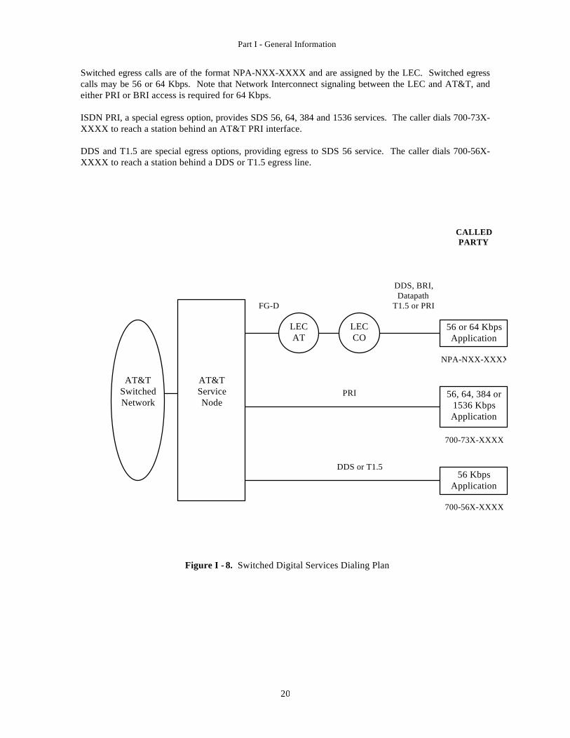
4.4.6 Switched Digital Services Dialing Plan
Figure I - 8 shows the dialing plan for the Switched Digital Services. Three scenarios are shown: switchedegress, ISDN PRI egress, and DDS/T1.5 special egress.
Application
ISDN
Premises
Controller
AT&TSwitchedNetwork
PRI (23 B+D)
NFAS T1.5 (24 B)(Non-Facility Associated Signaling)
Part I - General Information
20
Switched egress calls are of the format NPA-NXX-XXXX and are assigned by the LEC. Switched egresscalls may be 56 or 64 Kbps. Note that Network Interconnect signaling between the LEC and AT&T, andeither PRI or BRI access is required for 64 Kbps.
ISDN PRI, a special egress option, provides SDS 56, 64, 384 and 1536 services. The caller dials 700-73X-XXXX to reach a station behind an AT&T PRI interface.
DDS and T1.5 are special egress options, providing egress to SDS 56 service. The caller dials 700-56X-XXXX to reach a station behind a DDS or T1.5 egress line.
Figure I - 8. Switched Digital Services Dialing Plan
AT&TSwitchedNetwork
AT&TServiceNode
LECAT
LECCO
56 or 64 KbpsApplication
56, 64, 384 or1536 KbpsApplication
56 KbpsApplication
DDS, BRI,Datapath
T1.5 or PRIFG-D
PRI
DDS or T1.5
700-56X-XXXX
700-73X-XXXX
NPA-NXX-XXXX
CALLEDPARTY

Part I - General Information
21
4.5 Switched Digital International (SDI)
SDI and SDDN-I complement the two domestic switched digital service families, Switched Digital Services(SDS) and SDDN, respectively. SDI and SDDN-I are offered on the same transport network platform.Any SDS customer may place an SDI call; only SDDN customers may place SDDN-I calls.
SDI and SDDN-I are currently available to numerous countries including some countries with multiplecarriers. Additional information may be found in the AT&T Business Communications Services Guide.
SDI and SDDN-I currently support 56 and 64 Kbps transport rates. SDI / SDDN-I 384 Kbps service issupported to a limited number of countries. Support of SDI / SDDN-I 1536 Kbps service is planned Theaccess arrangements shown in Figure I - 1 and Figure I - 2 apply to SDI and SDDN-I. Inverse multiplexer(see Figure I - 5) can be used on SDI and SDDN-I calls to provide nx56 and nx64 connections.
4.5.1 Inbound SDI Calls
The dialing plan for inbound SDI calls is the same as SDS, shown in Figure I - 8, with one exception.
The exception is for the following scenario:
• the inbound SDI call is to a station behind an ISDN PRI interface,
• the inbound SDI call is 56 Kbps, not 64 Kbps, and
• the signaling on the international link uses CCITT No. 7 TUP (Telephone User Part), not ISUP(ISDN User Part).
For this scenario, the dialed number is not 700-73X-XXXX as shown in Figure I - 8, but rather 700-56X-XXXX, 700-556-XXXX or 700-956-XXXX. Additional codes will be added as needed.
4.5.2 Outbound SDI Calls
The dialing plan for outbound SDI calls is:
Special access (Figure I - 1)
• ISDN PRI: 011+CC+NN
• DDS and T1.5: 173+CC+NN3
Switched access (Figure I - 2): 011+CC+NN
4.5.3 SDDN-I Calls
Currently, international on-net to on-net connectivity for data traffic is not supported by AT&T (it isplanned for introduction as part of a Global Software Defined Data Network -- GSDDN -- service offering).
3. The 173 access code used with DDS and T1.5 will be phased out in favor of the 011 access code.

Part I - General Information
22
Domestic SDDN customers who wish to receive inbound international calls may do so by subscribing to theSDDN 700 In-Dial capability (Figure I - 4), described in Section 4.1.4.
The dialing plan for outbound SDDN-I calls (on-net to off-net, Figure I - 3) is defined in Section 4.1.2 andin AT&T TR41459 (ISDN PRI).
4.6 Alternate Egress Arrangement (AEA) For Long Distance Service
AEA will terminate ASN calls directly to the customer premises. It will be provisioned on an individualcase basis at locations with sufficient traffic volumes over dedicated facilities arranged by the customer. Itmay be part of a package offered with other AT&T communications services.
AEA will redirect inter-LATA ASN switched traffic which is billed to both the call originators and the callreceivers. Calls may originate over many AT&T services, such as DDD, AT&T Card, WATS,MEGACOM, CNO Off-Net, CCSA Off-Net, SDN Off-Net, IDDD, and other services which are billed tothe call originator. Any other AT&T Inbound Service which is normally served by the LEC Class 5 Officeat the terminating location will also be included. AEA will not impact the rates charged for these services.
Services requiring special access facilities, such as Toll Free MEGACOM and on-net traffic cannot beincluded in an AEA.
The provider of each AEA must commit to furnish a quality of service that meets the performancerequirements of the ASN. This quality of service must include service availability, mean time betweenfailure, mean time to repair transmission parameters, and accuracy of usage information.
AEA will be provided where the customer has the complete range of stations behind the d-digits (thousandsseries). Calls may be screened down to the tens group of numbers. The customer will receive the complete7-digit message network number and will be fully responsible for switching the call to the appropriatestation.
AT&T will implement AEA at locations:
• Which attract sufficient calling volumes
• Where the customer has a complete thousands series (or multiples thereof) range of stations.
• Where the customer has deployed CPE which AT&T has approved for interconnection as a switchingdevice of the ASN. The CPE must provide the same functionality for answer supervision andsignaling that is provided by the LEC Class 5 Office in the traditional method of switched trafficegress. Customer locations served by a CENTREX may be included in an AEA.
4.7 MultiQuest 900 Service
The AT&T MultiQuest (MQ) Service provides 900-inward calling to customers with direct egress from anAT&T Service Node. This domestic service is targeted for high volume inward calling terminating at thesponsor’s location.
MultiQuest was introduced by AT&T to allow our customers (sponsors) to offer a valued service to theirclients (callers) and charge premium rates. Sponsors will choose the premium charge they wish to applyunder a Premium flexible billing agreement.
Callers can dial a 900 number, complete to customer’s premises multiplexing equipment over T1.5 egressfacilities and communicate with live attendants, voice messaging equipment, and computer databases to

Part I - General Information
23
obtain value-added services. This interactive capability distinguishes MultiQuest from DIAL-IT 900Service. Callers pay for the customer’s service via a premium charge on their telephone bill. Thesecharges are forwarded to the customers by AT&T after certain transport and contract deductions have beenmade.
MultiQuest customers must comply with the Federal Trade Commission (FTC) rules pursuant to theTelephone Disclosure and Dispute Resolution Act (TDDRA), (FTC file number R311001, 900 Pay-Per-Call).
4.7.1 Special Features
• Call Detail Report - Bill analysis gives the customer, at no charge, a list of individual calls on theirTSGs with complete call details. Call charges and total monthly charges will also appear.
• Executive Summary Report - A monthly report that customers will receive, at no charge, for the priorbilling period, which provides summary usage information by NPA for each AT&T MQ 900 number.
• Flexible Billing - Allows a sponsor to charge any rate that they want, subject to AT&T’s parameters,on a per 900 number basis. The sponsor will no longer use a fixed rate associated with a 900 number.If the sponsor wishes to change the rate, the 900 number can remain the same .
• Electronic Funds - Allows a sponsor to receive premiums directly into their account via an AT&Ttransfer procedure.
• ANI Delivery (see Section 4.3.1)
The Call Management Features for MQ are identical to the Advanced 800 FCC Tariff No. 2 Offerings,with the exception of Courtesy Response. Additional features and information may be found in the AT&TBusiness Communications Services Guide.
4.7.2 Dialing Plan
Callers will originate a call to a sponsor by dialing “1-900-NXX-XXXX”.
• MQ uses a SAC, which is a subset of the NANP standard (1-900-NXX-XXXX).
• Dialable numbers are allocated to carriers on a six digit basis (900-NXX).
• Originating calls are switched through the LEC office.
4.8 M44X Multiplexing
M44X is a multiplexing service function of T1.5 service that is fully described in AT&T TechnicalReference PUB 54070. The M44X multiplexing service function typically allows a maximum of 4432Kbps channels to be transmitted on a single 1.544 Mbps transmission facility .
M44X, using ADPCM devices such as the BCM 32000X, will ONLY be allowed on circuit configurationsfor MEGACOM, Toll Free MEGACOM, and MultiQuest Service. 9.6 Kbps analog data will not besupported. 4.8 Kbps and voice applications will be fully supported.
When BCM 32000X is used and the round trip delay on the access facility exceeds 11 ms, it may benecessary to have the customer to provide echo cancelers on the non-compressed inputs of the M44Xmultiplexing device at the customer premises.

Part I - General Information
24
4.9 Toll Free Multimedia
AT&T’s Toll Free Multimedia Service allows customers to receive data and voice calls on the same tollfree number. It is a dial-up service for multimedia offerings which are various combinations of video, voiceand data on a single connection. The service will support originating access by:
• 64 Kbps clear connection on an ISDN BRI ordered from the Local Exchange Carrier, whereavailable,
• any form of switched 56 Kbps service (e.g., Switched Digital 56 Service) tested by the LEC for usewith the Toll Free Multimedia Service,
• voice (see Section 4.3),
• 384 Kbps connection on an ISDN Primary Rate Interface (planned).
Subscribers must connect to the network via ISDN PRI at the terminating location. Additional informationmay be found in the AT&T Business Communications Services Guide.
4.9.1 Dialing Plans
AT&T’s Toll Free Multimedia Service customers can be reached from switched access locations using anumber of the 8YY-NXX-XXXX format.
4.10 Universal T1.5 Access
Universal T1.5 Access allows multiple services to be carried over a single T1.5 using either DP, DTMF,MF or ISDN PRI signaling.
The capabilities and services that can be carried on a Universal T1.5 Access trunk include:
• Access Services
◊ MEGACOM
◊ Operator requested calls
• Egress
◊ Toll Free MEGACOM
◊ Long Distance Service
• Two-Way Service
◊ SDN
◊ SDS capabilities (planned)
Depending on the signaling associated with the customer’s T1.5, it may not be possible to offer all of thecapabilities on the same trunk. Only ISDN PRI trunks are capable of supporting more than one 1+ voice

Part I - General Information
25
service on access; all other arrangements must choose between SDN or MEGACOM. In addition, DP,MF and DTMF trunks are unable to support data rates in excess of 56 Kbps.
4.10.1 Dialing Plans
The dialing plans for the respective services shall apply to Universal T1.5 Access. Customers can reachAT&T Operator Services by using numbers of the following format:
• 00
• 0-NXX-XXXX
• 0-NPA-NXX-XXXX
International Operator Services may be reached by dialing a number of the 01+CC+NN format.

Part I - General Information
26
5. GLOSSARY OF TERMS AND ACRONYMS
Access Line or Trunk: In the context of this document, the term access line or trunk refers to a specialaccess, DS-0 level or voiceband analog channel extending from an ACP to a customer’s premises. Anaccess line or trunk may be carried over two-wire ground start, four-wire E&M, or DDS facilities, or maybe one of the twenty four DS-0 channels within a DS-1 level facility.
ACP: See Action Point.
Action Point (ACP): An intelligent node at the edge of the AT&T network which accepts user’s callrequests, and under stored program control can provide the required routing, billing, record keeping, andother necessary functions.
Alternate Mark Inversion (AMI): A digital line coding scheme in which binary ones are represented bypulses which alternate in polarity, and binary zeros are represented by the absence of pulses. Any violationof this polarity alternation may be regarded as an indication of a transmission error, so some types ofterminal equipment log bipolar violations for maintenance purposes.
Answer Signal: An off-hook indication transmitted by a called CPE toward the egress ACP to indicatethat the call has been answered. If so provisioned, the answer signal propagates back to the calling CPE orLEC switching office.
Audible Ring Tone: A tone transmitted to the calling CPE to indicate that the called CPE is being alertedof the incoming call. Audible ring tone is transmitted over the voice channel of four-wire analog facilities,or is PCM encoded on DS-1 facilities.
AMI: See Alternate Mark Inversion (AMI).
B8ZS: See Bipolar with 8 Zero Substitution (B8ZS).
BER: See Bit Error Rate.
Bipolar with 8 Zero Substitution (B8ZS): A digital line coding scheme which is similar to AMI, butwhich ensures sufficient pulse density on a DS-l facility. B8ZS is especially important when transmittingdigital data, since DS-1 receiver clock circuits must synchronize to the pulses in the received signal; digitaldata can contain long strings of zeros, which, if not for the B8ZS scheme, would result in extended periodsduring which the signal would have no pulses, and therefore be problematic. B8ZS enforces the pulsedensity constraint by encoding each string of eight consecutive zeros as a special bipolar violationsequence.
Bit Error Rate (BER): A figure of merit for digital communications systems computed by dividing thetotal number of bits received in error in a given time interval by the total number of bits transmitted in thatsame time interval.
Channel Bank: Terminal equipment for transmission system used to multiplex individual channels usingeither Time Division Multiplexing (TDM) or Frequency Division Multiplexing (FDM) techniques fortransmission over a higher-bandwidth carrier system. While other types exist, only SF-compatible andESF-compatible digital channel banks are relevant to this document. This type of channel bankmultiplexes 24 lower-bandwidth signals, on a time-division basis, for transmission over a digital carriersystem. The lower-bandwidth signals may be encoded analog (e.g., 2-wire ground start, 4-wire E&M, etc.)or digital (e.g., 56 Kbps DDS line coding). The associated channel units perform whatever analog-to-

Part I - General Information
27
digital conversion or digital line coding conversion is necessary. The demultiplexing operation is theinverse of the multiplexing operation.
Centrex: A local, LEC-owned switching system which connects subscriber lines and provides PBX-likefeatures.
Class 5 Central Office: A local, LEC-owned switching system, which connects subscriber lines to othersubscriber lines or to interoffice trunks.
CPE: Customer Premises Equipment.
CPE&A: Customer Premises Equipment plus the Access facilities, viewed as a single arrangementinterfacing to AT&T’s nodal services at the AT&T point of termination.
Data Communications Equipment (DCE): Customer premises equipment which adapts digital signalsfrom data terminal equipment to a format suitable for transmission over the network, and which controlsthe connection.
Data Terminal Equipment (DTE): In the context of this document, customer premises equipment whichis a source and/or sink of digital information. DTE usually cannot terminate a subscriber line, access line,or trunk directly, and therefore must connect to the network through data communications equipment(DCE).
DCE: See Data Communications Equipment.
DDSD: See Delay-Dial Start-Dial signaling.
Decode Loss: The level (in dBm) of a 1004 Hz sinusoid which would result if a digital reference signalwas decoded by a zero level decoder.
Delay-Dial Start-Dial Signaling (DDSD): A method of engaging a trunk or access line to set up a call,performing an integrity check on it, and establishing a proper time to transmit address information. Forexample, suppose a call comes into a PBX over a DDSD access line. The ACP alerts the PBX of the call bytransmitting off-hook, i.e. by seizing the access line. The PBX transmits off-hook toward the ACP until itis ready to receive DID address information. This is the delay-dial signal. When ready to receive addressdigits, the PBX transmits on-hook. The off-hook to on-hook transition constitutes the start-dial signal andis analogous to dial tone. The ACP, satisfied that the channel and PBX are operational (since it hasreceived the delay-dial and start-dial signals), transmits the address information.
Dial Pulse Signaling (DP): A means of address signaling accomplished by momentary on-hookexcursions or pulses, whereby the number of such pulses corresponds to the value of the digit.
DID: See Direct Inward Dialing.
Digital Milliwatt: A defined, standardized sequence of PCM words, which when decoded through a zerolevel decoder, produces a 0 dBm, 1000 Hz sinusoid. Because the digital milliwatt is a finite sequence it isconvenient in defining the concept of loss between a digital transmission system and an analog system.However, its utility is purely mathematical; it should not be applied to an actual digital transmissionsystem. The recommended test signal for that purpose is the Digital Reference Signal (DRS).
Digital Reference Signal (DRS): A sequence of PCM words, which when decoded by a zero-leveldecoder, results in a 0 dBm sinusoid with a nominal frequency of 1004 Hz. DRS differs from the digitalmilliwatt in that (a) the decoded sinusoid will have a slightly different frequency (1004 Hz as opposed to

Part I - General Information
28
1000 Hz), and (b) DRS is not a finite, deterministic sequence. DRS is the correct signal for testing andadjusting digital transmission systems.
DL: See Decode Loss.
DP: See Dial Pulse signaling.
Direct Inward Dialing (DID): A feature that permits incoming calls to stations served by a PBX or otherCPE to be dialed directly; the call need not go through an attendant.
DS-0: Digital Signal level 0. See also DS-1.
DS-1: In the time division multiplexing hierarchy of the telephone network, DS-1 (Digital Signal level 1)is the initial level of multiplexing. Traditionally, twenty four 64 Kbps DS-0-level channels have beenmultiplexed up to the 1.544 Mbps DS-1 rate, with each DS-0 level channel having the capability ofcarrying the digital representation of an analog voice channel or digital data in various formats.
DTE: See Data Terminal Equipment.
DTMF: See Dual-Tone Multifrequency.
Dual-Tone Multifrequency Signaling (DTMF): A means of address signaling that uses a simultaneouscombination of one of a lower group of frequencies and one of a higher group of frequencies to representeach digit or character. DTMF is the signaling method used by modern Touch-Tone telephone sets.DTMF is not the same as multifrequency (MF).
EL: See Encode loss.
Encode Loss (EL): A unitless number which relates the equivalent power represented by the digital outputsignal of an encoder to the analog power level at the input to the encoder.
ESF: See Extended SuperFrame (ESF) framing and formatting.
Extended SuperFrame (ESF) Framing and Formatting: A time division multiplexing standard used onDS-1 level channels to carry 24 DS-0 level channels. In addition to the features available with SF framingand formatting, ESF offers more robbed bit signaling channels (four, as compared with only two availablewith SF), a 4 Kbps data channel (reserved for remote alarm indication (yellow alarm) transmission andmaintenance purposes), and a Cyclic Redundancy Check (CRC) code. Additionally, the ESF standardcircumvents certain situations which could lead to false framing capture and false remote alarm indicationrecognition if SF framing was used. These new features make ESF the preferred standard for new specialaccess installations. See AT&T Technical Reference TR 54016 for details.
Glare: The condition in which call attempts are simultaneously initiated at both ends of the same two-waytrunk or access line. Procedures exist for detecting and gracefully resolving glare on wink start and DDSDtrunks and access lines, but not for immediate start access lines.
ICL: Inserted Connection Loss.
Immediate Start: A method of engaging a trunk or access line in which no start-dial signal is used. Theinitiating CPE or office simply seizes the trunk or access line and begins sending address digits.
LEC: Local Exchange Carrier.

Part I - General Information
29
M24: A multiplexing function, provided at an AT&T serving office, which provides for characterizationof Tl.5 Service circuit and allows for connection of the channels to the individual switched and non-switched services offered by AT&T. Refer to AT&T Technical Reference TR 62411 for additionalinformation.
MF: See Multifrequency signaling.
Multifrequency (MF): A type of address signaling in which ten decimal digits and five auxiliary signalsare each represented by selecting a pair of frequencies out of the following group: 700, 900, 1100, 1300,1500, and 1700 hertz (HZ). MF is not the same as DTMF.
NPA: See Numbering Plan Area.
Numbering Plan Area (NPA): Often, NPA refers to a geographical division defined by the familiar areacode, within which telephone directory numbers are subgroups. Current NPAs are of the form “NXX”,where:
N = any digit 2 through 9
X = any digit 0 through 9
A few NPA codes within the North American Numbering Plan have been assigned for special uses (such as8YY for Toll Free service) and are known as Service Access Codes (SACs). The 8YY NPA is sharedamong the service providers for their service offerings. The 700 NPA has been set aside for any inter-exchange carrier to use for any purpose such as identifying special access endpoints. In this document, theterm NPA simply implies a dialed number field having the form NXX, and may be either a geographicallysignificant area code or a Service Access Code.
One-Way Incoming Trunk or Access Line: In this document, a trunk or access line which can only beseized for use by the ACP is designated one-way incoming. The term incoming refers (in this document) tothe CPE viewpoint. Once a trunk or access line is seized, 2-way transmission may occur; one-wayincoming refers only to the direction of call initiation.
One-Way Outgoing Trunk or Access Line: In this document, a trunk or access line which can only beseized for use by the CPE is designated one-way outgoing. The term outgoing refers (in this document) tothe CPE viewpoint. Once a trunk or access line is seized, 2-way transmission may occur; one-wayoutgoing refers only to the direction of call initiation .
PBX: See Private Branch Exchange.
Private Branch Exchange (PBX): A private switching system, either manual or automatic, usuallyserving an organization such as a business or a government agency, and usually located on the customer’spremises.
Robbed Bit Signaling: A supervisory signaling scheme used in SF and other DS-l framing and formattingstandards, in which the least significant bit of a channel’s time slot is preempted in selected frames. In SFframing and formatting, two robbed bit channels are available. These are sometimes referred to assignaling channels A and B. In ESF framing and formatting, there are four robbed bit channels, labeled A,B, C, and D. When robbed bit signaling is used in digital data channels such as are used in DS-l specialaccess to Switched Digital 56 Service, the bit position where bits may be robbed (i.e., the least significantbit) is not available for user data. See also Supervisory signaling.
SF: See Superframe.

Part I - General Information
30
Signaling Bit: See robbed bit signaling.
Special Access: Connection of CPE to the AT&T network using dedicated special access service.Although the special access facilities are normally obtained from the LEC (if the CPE and AT&T servingoffice are in the same LATA), no LEC switching equipment is employed .
Station: In this document, the customer premises equipment which is the endpoint of a call. A stationcould be, for example, a telephone set or DTE and associated DCE behind a digital PBX served by specialaccess, or a DTE and associated TIU served by a single channel special access line.
Subscriber Line: The facility which extends from a LEC class 5 central office to a customer premises andconnects to the customer’s station equipment to the LEC switched network.
Superframe (D3/D4) Framing and Formatting: A time division multiplexing standard used on DS-llevel channels to carry 24 DS-0 level channels. Formatting, or channelization format, refers to thesequencing of the 24 time-slots and allocation of the time-slots to their respective DS-0 channels. Framingrefers to a synchronization pattern used to establish the time-slot. See AT&T Technical Reference TR62411 for details of Superframe (SF) and Extended Super Frame (ESF) formats.
Supervisory Signaling: Signaling used to indicate or control the states (e.g. on-hook, off-hook) of circuitsinvolved in a particular connection.
T1.5 Service: A two-point, dedicated, high capacity, digital service provided on terrestrial digital facilitiescapable of transmitting 1.544 Mbps. Refer to AT&T Technical Reference TR 62411 for additionalinformation on T1.5 service and its functionality.
Terminal Interface Unit: Adapts the DDS line coding to a standard DCE/DTE interface (such as V.35 orRS-449/422).
TIU: See Terminal Interface Unit.
Touch-Tone: See Dual-Tone Multifrequency.
Trunk: A communication channel between two switching systems. See also Access line or trunk.
Two-Way Trunk or Access Line: A trunk or access line that can be seized for use by equipment at eitherend of the trunk or access line.
Wink Start: A method of engaging a trunk or access line to set up a call, performing an integrity checkon it, and establishing a proper time to transmit address information. At first glance, wink start may beviewed as a special case of DDSD, where the delay-dial signal is of a short, specified duration. (There is,however, a difference between the glare resolution timing used in wink start and that used in DDSD.)
ZCS: See Zero Code Suppression (ZCS).
Zero Code Suppression: A method of providing pulse density enforcement which changes the secondleast significant bit in any all-zeros octet to a binary one. The ZCS mechanism acts on a per-channel basis,so that any alteration of user information is localized to the particular timeslot in which pulse densitywould otherwise be low. (This per-channel feature of ZCS contrasts with the method of pulse densityenforcement used by several channel service units to provide average pulse density requirements; the lattermethod typically disregards timeslot boundaries).

Part I - General Information
31
Zero Level Decoder: A hypothetical PCM decoder, which accepts 8-bit 11-255 PCM words at its input,and interpolates and expands the samples into an analog output signal. Given a digital milliwatt as itsinput, the zero level decoder output will be a 0 dBm, 1000 Hz sinusoid .

Part I - General Information
32
REFERENCES
1 AT&T, Special Access Connections to the AT&T Communications Network for New ServiceApplications, Technical Reference PUB 41458, April, 1990.
2 AT&T, Interface Specifications for Voice Grade Common Control Switching Arrangement (CCSA)and Enhanced Private Switched Communication Services (EPSCS), Technical Reference PUB 43252,October 1987.
3 AT&T Integrated Services Digital Network (ISDN) Primary Rate Interface and Special ApplicationSpecification User-Network. Interface Description, Technical Reference TR 41459, August 1996.
4 AT&T, Access Connections to Baseline Offerings at AT&T Central Offices, Technical Reference62210, May 1985.
5 AT&T Business Communications Services Guide, Document Number 015-358-027, June 1995.
6 AT&T Digital Data System Channel Interface Specification, Technical Reference 62310, November1987.
7 AT&T ACCUNET T1.5 Service Description and Interface Specification, Technical Reference 62411,December 1990.

Special Access Connections
To The
AT&T Network
Part II
Special Access Interconnection
At The
AT&T Point Of Termination

i
CONTENTS
1. SPECIAL ACCESS ELECTRICAL AND LOGICAL INTERFACES.........................................................................1
1.1 TWO-WIRE LINES AND TRUNKS..................................................................................................................................11.1.1 2-wire Loop Start (2LS) and 2-wire Ground Start (2GS).....................................................................................11.1.2 2-wire loop Reverse-Battery (2RB).....................................................................................................................2
1.2 FOUR-WIRE E&M TRUNKS ........................................................................................................................................31.2.1 Voiceband Transmission.....................................................................................................................................41.2.2 Supervisory Signaling........................................................................................................................................4
1.3 TRUNKS PROVIDED OVER TL.5 ACCESS.......................................................................................................................41.3.1 Information Encoding........................................................................................................................................4
1.3.1.1 Pulse Code Modulation................................................................................................................................................. 41.3.1.2 56 Kbps Digital Data.................................................................................................................................................... 5
1.3.2 Supervisory Signaling........................................................................................................................................51.3.2.1 On-Hook....................................................................................................................................................................... 51.3.2.2 Off-Hook....................................................................................................................................................................... 51.3.2.3 False Off Hook.............................................................................................................................................................. 5
1.4 56 KBPS SINGLE CHANNEL.........................................................................................................................................61.4.1 Information Encoding........................................................................................................................................61.4.2 Supervisory Signaling........................................................................................................................................6
1.4.2.1 On-Hook....................................................................................................................................................................... 61.4.2.2 Off Hook....................................................................................................................................................................... 7
1.4.3 Termination of DDS Access Facility...................................................................................................................7
2. CALL CONTROL PROCEDURES...........................................................................................................................11
2.1 IDLE STATE..............................................................................................................................................................122.2 WINK START............................................................................................................................................................12
2.2.1 Trunk Seized by Calling CPE&A......................................................................................................................122.2.2 Trunk Seized by ACP........................................................................................................................................132.2.3 Glare Resolution..............................................................................................................................................13
2.3 DELAY-DIAL / START-DIAL......................................................................................................................................142.3.1 Trunk Seized by Calling CPE&A......................................................................................................................142.3.2 Trunk Seized by ACP........................................................................................................................................152.3.3 Glare Resolution..............................................................................................................................................15
2.4 IMMEDIATE START ...................................................................................................................................................152.4.1 Trunk Seized by Calling CPE&A......................................................................................................................162.4.2 Trunk Seized by ACP........................................................................................................................................16
2.5 DIAL TONE START....................................................................................................................................................172.5.1 Trunk Seized by Calling CPE&A......................................................................................................................17
2.6 DISCONNECTION......................................................................................................................................................172.6.1 Calling CPE&A Procedures.............................................................................................................................18
2.6.1.1 Calling CPE&A Hangs Up First.................................................................................................................................. 182.6.1.2 Called CPE&A Hangs Up First................................................................................................................................... 18
2.6.2 Called CPE&A Disconnect Procedures............................................................................................................182.6.2.1 Calling CPE&A Hangs Up First.................................................................................................................................. 182.6.2.2 Called CPE&A Hangs Up First................................................................................................................................... 18
3. ADDRESS DIGIT TRANSMISSION........................................................................................................................19
3.1 DIAL PULSE .............................................................................................................................................................19

ii
3.1.1 ACP Dial Pulse Generation..............................................................................................................................193.1.2 ACP Dial Pulse Reception................................................................................................................................20
3.2 DUAL TONE MULTIFREQUENCY................................................................................................................................203.2.1 DTMF Digit Generation...................................................................................................................................213.2.2 DTMF Digit Registration.................................................................................................................................21
3.3 MULTIFREQUENCY...................................................................................................................................................213.3.1 MF Digit Generation........................................................................................................................................223.3.2 MF Digit Registration......................................................................................................................................22
4. CALL PROGRESS SIGNALS..................................................................................................................................24
5. TRANSMISSION LOSS AND LEVELS...................................................................................................................24
5.1 OTHER TECHNICAL REFERENCES AND STANDARDS....................................................................................................245.1.1 ANSI Standard EIA/TIA-464B..........................................................................................................................245.1.2 Bell Communications Research TR-NPL-00035, TR-NPL-00034 and PUB 62508............................................255.1.3 AT&T TR 41459...............................................................................................................................................255.1.4 Relationship Between Analog and PCM Transmission Levels...........................................................................255.1.5 Transmission Levels at the AT&T Point of Termination....................................................................................26

iii
LIST OF FIGURES
FIGURE II - 1. SEVERAL EXAMPLES OF SPECIAL ACCESS INTERFACES TO AN ACP ................................................................3FIGURE II - 2. BIPOLAR VIOLATION SEQUENCES ON 56KBPS SINGLE CHANNEL ACCESS. .......................................................8FIGURE II - 3. THE DIGITAL MILLIWATT. .......................................................................................................................26
LIST OF TABLES
TABLE II - 1. ALLOWED COMBINATIONS OF ADDRESS AND METHOD OF OPERATION ON E&M..............................................9TABLE II - 2. ALLOWED COMBINATIONS OF ADDRESS AND START-DIAL SIGNALING ON 56 KBPS SINGLE CHANNEL SPECIAL
ACCESS LINES...........................................................................................................................................10TABLE II - 3. COMPONENT FREQUENCIES FOR DTMF DIGITS...........................................................................................20TABLE II - 4. MULTIFREQUENCY CODES USED ON SPECIAL ACCESS...................................................................................21TABLE II - 5. CADENCES, FREQUENCY COMPONENTS, AND POWER LEVELS (PER FREQUENCY) OF CALL PROGRESS SIGNALS
GENERATED AT THE ACP..........................................................................................................................24TABLE II - 6. TRANSMISSION LEVELS AT THE POINT OF TERMINATION SERVICE NODE .....................................................27

Part II - Special Access Interconnection at the AT&T Point of Termination
1
1. SPECIAL ACCESS ELECTRICAL AND LOGICAL INTERFACES
This section lists the voice and data transmission channels and the trunk supervision signalingmechanisms used on the various special access facilities which connect to an ACP. Except for the 56Kbps single channel access arrangement, these are standard telephony interfaces. The reader shouldrefer to Table I - l in Part I, which lists availability by service, of each of these interfaces. Figure II -1 shows several examples of the special access interfaces to an ACP.
Note: This discussion applies to signaling dialog at the AT&T point of termination. Accordingly,the customer premises equipment and the access facilities (CPE&A) which may or may not becoordinated through AT&T are viewed as a single entity. It is the responsibility of the CPE vendorto interpret the implications of this discussion on equipment design requirements. In installationsemploying total or coordinated access, AT&T will engineer the access facility requirements.Otherwise, access facility engineering will be the customer's responsibility.
Tolerances for signals detected by AT&T equipment reflect worst case limits. Dispersion, band-limiting, and other distortions may be impressed on the signal during its propagation over the accessfacility. CPE vendors should allow for these distortions. (ANSI recommendation EIA/TIA-464Bprovides conservative CPE design criteria with the appropriate margins built in.)
1.1 Two-Wire Lines and Trunks
Two-wire special interface access for lines and trunks is available only on the selected AT&T nodalservices indicated in Part I, Table I-l. Moreover, voiceband data users should consider choosing afour-wire interface over a two-wire loop start or ground start interface, since the transmission qualityof four-wire access facilities is generally superior to that of two-wire access facilities.
1.1.1 2-wire Loop Start (2LS) and 2-wire Ground Start (2GS)
Special access loop start and ground start interfaces support one-way incoming, one-way outgoingand two-way trunks. Since glare can occur on 2-way trunks, and since 2LS provides no indication ofglare to the CPE&A, 2LS signaling is not recommended for 2-way trunks.
The following characteristics apply to both the special access loop start and ground start interfaces:
1. In the inward direction (i.e., towards the CPE&A), trunks are attendant-handled; DirectInward Dialing is not available.
2. In the outward direction, trunks always use Direct Outward Dialing.
3. Dial tone is provided by the network.
4. The network provides 20 Hz power ringing current to the called CPE&A.
5. Either dial pulse or DTMF address signaling is accepted.
6. Electrical characteristics of both interfaces are typical of industry-standard, two-wire loopstart and ground start interfaces.

Part II - Special Access Interconnection at the AT&T Point of Termination
2
1.1.2 2-wire loop Reverse-Battery (2RB)
The special access loop reverse-battery interface is typical of industry-standard loop reverse-batteryinterfaces. It is used for one-way incoming (to CPE&A) trunks, and is the only special access, two-wire interface on which Direct Inward Dialing (DID) is available. The CPE&A may operate in winkstart, delay-dial / start-dial, or immediate start mode, indicating the trunk supervisory signaling stateby reversing the battery polarity (wink start is recommended). The network will, at the customer'soption, transmit address information toward the CPE&A in the form of dial pulses (as described inSection 3.1.1) or DTMF digits (as in Section 3.2.1). Dial pulses will be conveyed by loop pulsing;battery and ground pulsing is not available. Call control procedures and relevant timing parametersare described in Section 2 and its subsections. CPE&A must provide any appropriate call progresstones (e.g., audible ring tone, busy, etc.), and must return an answer signal (i.e., battery reversal)within 500 ms. after the station party has answered.

Part II - Special Access Interconnection at the AT&T Point of Termination
3
Figure II - 1. Several examples of special access interfaces to an ACP
(other access interfaces, as specified in Table II - 1 and Table II - 2 are also available)
1.2 Four-Wire E&M Trunks
Four-wire E&M trunks are recommended for all new special access installations requiring analoginterface facilities. The material included here describes the termination characteristics presented to
DPBX
APBX
TIU
CU
DP
APBX
TIU
CU
DDSNetwork
AT&TSERVICE
NODE
56 Kbps
56 Kbps
56 Kbps
D4 ChannelBank
4-Wire E&M
D4 ChannelBank
2-Wire Ground Start
Customer Premises Access Provider AT&T
B A
DDS
DS-1
DS-1
DS-1

Part II - Special Access Interconnection at the AT&T Point of Termination
4
the 4-Wire E&M facility by the network ACP, with regard to voiceband transmission andsupervisory signaling. Call Control procedures relevant to E&M trunks may be found in Section 2and its subsections.
1.2.1 Voiceband Transmission
The convention for which particular pairs the network ACP will transmit and receive on is describedin Bell Communications Research Technical Reference TR-NPL-000335. The ACP will presentnominal source and load impedances of 600 ohms, resistive, measured at the POT. Transmissionlevels for trunks are given in Section 5.
1.2.2 Supervisory Signaling
AT&T supports E&M signaling types I, II, and III, but some access providers may choose not tooffer all three. Each of these signaling mechanisms is described in Bell Communications ResearchTechnical Reference TR-NPL-000335.
1.3 Trunks Provided Over Tl.5 Access
The DS-l access arrangement allows connection of CPE directly to a Network Action Point switch atthe carrier level. Figure II - 1 shows typical access architectures. Examples of CPE which areserved by the DS-l special access include (but are not limited to) Private Branch Exchanges (PBXs)and Automatic Call Distributors (ACDs). The PBX or ACD may connect to the network directly (ifequipped with DS-l trunk interfaces), or may connect to the network via a customer-provided digitalchannel bank (if the PBX or ACD is only equipped with analog trunk interfaces).
Currently, all DS-l special access interfaces within the scope of this section employ eitherSuperframe (SF, also known as D4), or Extended SuperFrame (ESF) framing format and SF channelsequence format. Bipolar with 8-Zero Substitution (B8ZS) line coding is preferred, but is notuniversally available on access links. If B8ZS is not available, Alternate Mark Inversion (AMI) linecoding is used instead. Voice and voiceband data are encoded using mu-255 pulse code modulation(PCM).
AT&T will be the master timing source, providing synchronization traceable to the PrimaryReference Source (PRS). The access facilities and the customer's CPE must therefore derive timing(i.e., loop-time) from AT&T's transmitted signal. For a discussion of loop timing, see AT&TTechnical Reference TR 62411. Further information on digital network synchronization may befound in AT&T Technical Reference TR 60110[1].
1.3.1 Information Encoding
This section contains specifications for encoding end-to-end user information (i.e., PCM voice ordigital data). Supervisory signaling is covered in Section 1.3.2.
1.3.1.1 Pulse Code Modulation
AT&T Technical References TR 43801[2] and TR 54016[3] provide a complete description of the SFand ESF framing standards, channel format and PCM encode/decode methods. Also see Section 5 ofthis document, and ANSI standard EIA/TIA-464B for transmission levels and encoding/decodingloss guidelines.
Part II - Special Access Interconnection at the AT&T Point of Termination
5
1.3.1.2 56 Kbps Digital Data
In addition to voice calls, 56 Kbps, synchronous, circuit switched digital data calls are possible whenthe Tl.5 access is used. This capability, which is used by the SDN and Switched Digital 56 Services,is full duplex unless the 56 Kbps digital broadcast capability is used (the 56 Kbps digital broadcastcapability is described in Part I).
Each word (i.e., “octet”) of a time slot consists of eight bits, numbered 1 through 8. Bit 8, which isthe least significant bit, is periodically robbed for signaling use and is subject to over-writing whencross-connect equipment is employed in the access. User data may occupy bits 1 through 7. Toassure network compatibility and end-to-end compatibility (which may involve dissimilar CPE),AT&T recommends that vendors adhere to the following conventions:
a) Binary “1”s are represented by pulses and binary “0”s are represented by the absence ofpulses.
b) Once a data call is set up, a binary “l” is transmitted in the eighth bit of all words of therelevant time slot (including words appearing in both signaling and non-signaling frames).
c) No all-zero words are transmitted in any time-slot. This constraint, known as the “per-channel pulse density constraint,” is met while the call is in progress by observingrecommendation (b) of this section. During call set-up, or while the trunk is idle, anymethod of per-channel pulse density enforcement is acceptable, provided it does notinterfere with normal framing, formatting, and supervisory signaling.
d) By convention, bits of information appearing in a time slot word are orderedchronologically, with bit 1 of the word representing the first bit of user data, and bit 7 of theword representing the last bit of user data.
1.3.2 Supervisory Signaling
Robbed bit supervisory signaling is used on all DS-l special access interfaces within the scope of thisdocument. Two robbed bit channels (A and B) exist within SF framing and formatting, and four (A,B, C, and D) exist within ESF. The ACP uses the A/B-bits (SF) or A/B/C/D bits (ESF) in a fashionthat is consistent with E&M channel units. Thus, only two supervisory states are used: "on-hook"and "off-hook." These are summarized below.
.
1.3.2.1 On-Hook
a) The CPE must transmit signaling bits A=B=0 (SF) or A=B=C=D=0 (ESF) as an on-hookindication.
b) The CPE must interpret a "0" in the received signaling bits as an on-hook indication fromthe ACP.
1.3.2.2 Off-Hook
a) The CPE must transmit signaling bits A=B=1 (SF) or A=B=C=D=1 (ESF) as an off-hookindication.
b) The CPE must interpret a "1" in the received signaling bits as an off-hook indication fromthe ACP.

Part II - Special Access Interconnection at the AT&T Point of Termination
6
1.3.2.3 False Off Hook
A prolonged Off-hook, without subsequent dialed digits being received, may be interpreted by theACP as a permanent seizure, and a fault on the channel, which may result in the channel beingremoved from service.
1.4 56 Kbps Single Channel
The 56 Kbps single channel special access is currently used for both the SDN and Switched Digital56 Services. (See Part I for a brief description of these services.)
Figure II - 1 includes one example of a typical 56 Kbps single channel installation. Here, a signalingconversion function at the AT&T Point Of Presence (POP) maps the robbed bit signaling present onthe DS-l facility into the Data and Control modes supported by the DATAPHONE Digital Service(DDS). This fact allows use of conventional, unmodified DDS facilities (without secondary channel)for access. The DDS access facilities extend from the AT&T Point of Presence to a TerminalInterface Unit (TIU) on the customer's premises. The TIU adapts the DDS line coding to a standardDCE/DTE interface (such as V.35 or RS-449/422), and performs the call control proceduresdescribed in Section 2. AT&T TR 62310 describes the DDS interface, including the Data andControl modes used to convey the supervisory signaling.
Call control procedures are consistent with Section 2 and its subsections, with some restrictions.These are explicitly noted where applicable. To encourage uniformity among access trunks, AT&Trecommends the use of wink-start procedures in the outward (from CPE&A) direction. In theinward direction, immediate start is typical on 56 Kbps single channel non-DID trunks, and Delay-Dial / Start-dial (with special requirements on delay-dial signal duration as noted in Section 2.3.2)must be used on 56 Kbps single channel DID trunks.
1.4.1 Information Encoding
User data is encoded onto the DDS loop as described in AT&T TR 62310. That document describeshow data is encoded in a bipolar, return-to-zero format, with a positive or negative pulserepresenting a binary "1" and the absence of a pulse representing a binary "0."
AT&T network equipment will interpret a Zero-code Suppression (ZS) sequence (see Figure II - 2b)as a string of seven consecutive binary "0"s in the user's data. If the CPE&A attempts to transmitmore than six consecutive, unsuppressed "0"s, the user data may be corrupted. Zero-codeSuppression sequences are also transmitted by the network toward the customer. It is possible thatthe network may transmit as many as twelve consecutive unsuppressed "0"s toward the CPE&A.Except for ZS sequences, no bipolar sequences are supported while a call is in progress. Forexample, Control Mode Idle (CMI) is not supported as an end-to-end signaling mechanism (as it isin conventional DDS), since the single channel access procedures use CMI for supervisory signaling,as described below. Only the 56 Kbps data rate is supported.
The equipment at the AT&T Point of Presence transmits and receives in synchronism with the BasicSynchronization Reference Frequency.
1.4.2 Supervisory Signaling
1.4.2.1 On-Hook
a) The network will interpret Control Mode Idle (CMI) codes as indicative of the on-hooksupervisory state. Figure II - 2a illustrates a typical CMI sequence.

Part II - Special Access Interconnection at the AT&T Point of Termination
7
b) The network will transmit CMI codes as an on-hook indication from the ACP.
1.4.2.2 Off Hook
a) The network will interpret the Data Mode as indicative of the off-hook supervisory state. Adata mode signal is characterized by one of the following two attributes:
i. Absence from bipolar violations.
ii. Zero-code Suppression (ZS) sequences, as in Figure II - 2b.
b) The network will transmit in Data Mode as an off-hook indication from the ACP.
1.4.3 Termination of DDS Access Facility
The customer has the responsibility of maintaining the proper TIU termination on the DDS accessfacility at all times. Removal of the termination, either by disconnecting or turning off power,causing the loss of CMI may be interpreted by the ACP as a fault on the channel, which may resultin the channel being removed from service.

Part II - Special Access Interconnection at the AT&T Point of Termination
8
0 B B 0 0 B 0 B B 0 B B B B X 0 V B B B B X 0 V B B B B X 0V
+E
-E
a) Control Mode Idle (CMI)
1 0 1 0 0 1 1 0 0 0 0 0 0 0 1 1 0 1 0 0 0 0 0 0 0 1 1 0
B 0 B 0 0 B B 0 0 0 0 X 0 V B B 0 B 0 0 0 0 X 0 V B B 0
+E
-E
b) Zero Code Suppression (ZS)
0 Denotes zero volts transmitted - binary zeroB Denotes + E volts transmitted (polarity determined by the bipolar rule) - binary one.V Denotes + E volts transmitted (polarity in violation of the bipolar rule) - binary one.X Equals 0 or B if the number of "B"s since the last "V" is odd or even, respectively. In example
(a), the number of "B"s since the last "V" (not shown) until the first "X” (shown) is assumed tobe odd. In example (b), it is assumed to be odd.
Figure II - 2. Bipolar violation sequences on 56Kbps single channel access.
OFF HOOK ON HOOK
X=0 X=B X=B
CMI
ZS
CMI CMI
X=B X=0
ZS

Part II - Special Access Interconnection at the AT&T Point of Termination
9
Table II - 1. Allowed combinations of address and method of operation on E&M
Directionality Inward (to CPE&A) Outward (from CPE&A)Start Address Start Address
lW OG Wink DPlW OG Wink MFlW OG IS DPlW OG Wink DTMFlW OG Dial Tone DP or DTMF (per call)lW IC Wink DPlW IC DDSD DPlW IC Wink MFlW IC DDSD MFlW IC IS/S-G DPlW IC IS Supp.lW IC Wink Supp.lW IC DDSD Supp.lW IC Wink DTMF2W Wink DP Wink DP2W Wink DP Wink MF2W Wink MF Wink DP2W Wink MF Wink MF2W DDSD DP Wink DP2W DDSD DP Wink MF2W DDSD MF Wink DP2W DDSD MF Wink MF2W Wink Supp. Wink DP2W DDSD Supp. Wink DP2W IS Supp. Wink DP2W IS Supp. Wink MF2W Wink DTMF Wink DTMF2W IS/S-G DP Dial Tone DP or DTMF (per call)2W DDSD DP Dial Tone DP or DTMF (per call)2W Wink DP Dial Tone DP or DTMF (per call)
Notes:
l. "Incoming" and "outgoing" refer to the CPE&A viewpoint.
2. CPE&A may be administered for DDSD instead of wink start in the outward direction, since thewink sent by the ACP will be interpreted by the CPE&A as a DDSD signal. The glare resolutionprocedures, however, are faster for wink start than for DDSD. It is therefore recommended thatwhenever possible, CPE&A be administered for wink start instead of DDSD in the outwarddirection.

Part II - Special Access Interconnection at the AT&T Point of Termination
10
Abbreviations (Directionality):
1W OG One way outgoing access line.
lW IC One way incoming access line.
2W Two way access line.
DP Dial Pulse signaling.
Supp. Suppressed outpulsing of address information.
IS Immediate Start.
IS/S-G Immediate Start / Stop-Go.
DDSD Delay-Dial / Start-Dial.
Abbreviations (Address Signaling):
MF Multifrequency signaling.
DTMF Dual-tone multifrequency.
Abbreviations (Supervisory Signaling):
E&M Ear and Mouth
LS Loop Start
GS Ground Start
Table II - 2. Allowed combinations of address and start-dial signaling on 56 Kbps single channelspecial access lines.
Directionality Inward (to CPE&A) Outward (from CPE&A)Start Address Start Address
lW OG Wink DPlW IC IS Supp.lW IC DDSD DP
2W DDSD DP Wink DP2W IS Supp. Wink DP

Part II - Special Access Interconnection at the AT&T Point of Termination
11
Notes:
1. "Incoming" and "outgoing" refer to the CPE&A viewpoint.
2. CPE&A may be administered for DDSD instead of wink start in the outward direction, since thewink sent by the ACP will be interpreted by the CPE&A as a DDSD signal. The glare resolutionprocedures, however, are faster for wink start than for DDSD. It is therefore recommended thatwhenever possible, CPE&A be administered for wink start instead of DDSD in the outwarddirection.
Abbreviations:
lW OG One way outgoing access line.
lW IC One way incoming access line.
2W Two way access line.
DP Dial Pulse signaling.
Supp. Suppressed outpulsing of address information.
IS Immediate Start.
DDSD Delay-Dial Start-Dial.
2. CALL CONTROL PROCEDURES
This section includes call set-up scenarios relevant to special access. With caveats explicitly noted,and subject to availability as noted in Table II - 1 and Table II - 2, the procedures are applicable totwo-wire loop reverse-battery, four-wire E&M, DS-l, and 56 Kbps single channel special accesstrunks.
It is possible to mix signaling types on a given trunk (e.g., DDSD inward with wink start outward),but some signaling combinations are not allowed. Table II - 1 is a comprehensive list of signalingtype combinations allowed on E&M trunks and DS-l trunks. Combinations allowed on 56 Kbpssingle channel special access trunks are listed in Table II - 2.
Glare is the condition that exists when two switches each seize the same two-way trunk at about thesame time. Glare detection and resolution are specific to each call control procedure, and aredescribed in the relevant subsection. If a two-way trunk is shared by MEGACOM and/or Toll FreeMEGACOM, the ACP will resolve the glare. Otherwise, it is possible for a customer to choosewhether the glare will be resolved by the CPE&A or by the ACP. If the CPE&A is able to detect andresolve glare, it is usually advantageous that it do so on trunks not shared by MEGACOM and/orToll Free MEGACOM. Methods for detecting and resolving glare are given for wink start callcontrol in Section 2.2.3 and for delay-dial / start-dial call control in Section 2.3.3.
For various causes, known or unknown, there may be short changes (called hits) in the receivedsupervisory state. These may be either on-hook hits or off-hook hits. The ACP is reasonably

Part II - Special Access Interconnection at the AT&T Point of Termination
12
immune to hits. Typically, hits are of relatively short duration (compared with normal call controlsignals), and the ACP will ignore them on the basis of their short duration. Appropriate hit timingvaries with circumstance, and is specified where applicable. In any case, the ACP will ignorespurious signal transitions of duration less than 1 ms.
All flash timing should be handled within the CPE&A. No flashes should be presented to the ACP.
In the outward (i.e., from CPE&A) direction, all trunks use Direct Outward Dialing (DOD). In theinward direction, trunks may use Direct Inward Dialing (DID) or outpulsing may be suppressed atthe ACP.
2.1 Idle State
When the trunk is idle, both the CPE&A and the ACP are on-hook. The idle condition exists untileither the CPE&A or the ACP seizes the trunk.
2.2 Wink Start
Wink start is the preferred method of call control because it inherently offers an integrity check onthe trunk, and because it provides for rapid detection and resolution of glare on two-way trunks .
2.2.1 Trunk Seized by Calling CPE&A
From the idle state, the ACP will interpret a change in the CPE&A supervisory state to off-hook as atrunk seizure if the off-hook signal persists for at least 150 ms (30-40 ms if hit timing is specified).The ACP will continue to monitor the supervisory state of the trunk, and will interpret any on-hooktransitions as one of the following indications, depending upon the stage of the call processing andthe duration of the on-hook excursion:
a) dial pulses (during the addressing phase of the call, if dial pulse signaling is provisioned).
b) a disconnection (if the call completes normally).
c) call abandonment before completion.
d) glare resolution by the CPE&A (assuming the CPE&A is the glare-resolving party).
e) a hit.
The ACP will send the leading edge of the wink within 150 ms. after detection of the seizure. Thewink, as generated by the ACP, is a momentary, timed, off-hook signal, 140 to 290 ms. in duration.
The ACP will "blind" itself for the 70 ms. immediately following the trailing edge of the wink. Afterthe 70 ms. elapses, the ACP will be ready to register address digits in the form of dial pulses (Section3.1.2), dual tone multifrequency (Section 3.2.2), or multifrequency (Section 3.3.2) on E&M or DS-ltrunks. On 56 Kbps single channel access trunks, only dial pulse is allowed. The ACP must receivethe first digit from the CPE&A within the first 5 seconds for MF and 10 seconds for DTMF,immediately following the trailing edge of the wink. For DTMF, 15 seconds are allowed betweendigits, for MF, all digits after the first group of 4 digits (KP + 3D), must be received within 15seconds.
While the call is being set up, standard in-band call progress information (e.g., audible ring tone,busy, reorder, etc.) may be present on the transmission channel. For single channel access however,

Part II - Special Access Interconnection at the AT&T Point of Termination
13
depending on the particular access architecture, this call progress information may be either blocked,or not PCM byte synchronized. Therefore, the CPE&A should not always expect to receive standardPCM encoded call progress information, nor expect to receive uninterrupted CMI.
If answer supervision to the calling CPE&A is provided, the ACP will transmit an off-hook signaltoward the CPE&A to indicate that the far-end CPE&A has answered the call. The answer signalwill last for at least 2 seconds.
Answer delay varies with application. On a voice call, the answer delay depends on the humanresponse time. On a 56 Kbps data call, the called CPE&A often answers automatically, without needfor human interaction. Vendors of CPE&A for the 56 Kbps digital data capability are encouraged toprovide an answer-delay timer, the duration of which can be adjusted by the customer. For a 56Kbps call to a domestic destination, an answer delay of about 30 seconds appears appropriate.International call set-up times are longer than domestic call set-up times and may be highly variable.Vendors of CPE&A for use with the international 56 Kbps data capability should consider providingan answer-delay timer which is adjustable to at least 90 seconds.
2.2.2 Trunk Seized by ACP
The trunk is initially idle. The ACP seizes the trunk by changing its supervisory state to off-hook.
The ACP expects to receive a wink from the called CPE&A within 5 seconds. At this stage of thecall, the ACP will regard a momentary off-hook signal as a wink if it lasts longer than 100 ms. butless than 350 ms. The ACP will ignore spurious signal transitions following the start or end of awink for at least 3 ms. If no wink is received, the ACP will declare a wink time-out. Wink time-outs are logged at the ACP, since they indicate a problem with the facility or the far-end equipment(i.e., the CPE). Repeated wink time-outs can cause the trunk to be put in a "lockout" state.
On Direct Inward Dialing (DID) trunks, the ACP will begin to transmit address digits at least 70 ms.after it receives the wink. Address digits may be in the form of dial pulses (Section 3.1.1), dual tonemultifrequency (Section 3.2.1), or multifrequency (Section 3.3.1).
When and if the destination party answers, the CPE&A must return answer supervision to the ACPby going off hook. The answer signal should be returned within 500 ms. after the destination partyanswers, but not sooner than 70 ms. after the trailing edge of the wink. The CPE&A shouldmaintain this off-hook signal until the call is disconnected.
2.2.3 Glare Resolution
If the ACP seizes the trunk at about the same time as does the CPE&A, a glare condition exists. Asexplained in Section 2.2.1, the CPE&A expects the ACP to respond to a seizure by sending a wink.In a glare situation, however, the CPE&A detects an off-hook signal which persists too long to be awink.
If the CPE&A is the glare-resolving party, then the ACP will continue to assert its trunk seizure; itwill not return the trunk to the on-hook state, but will instead wait for the CPE&A to do so. Theglare condition will persist until the CPE&A aborts its call attempt by returning its supervisory stateto on-hook and preparing to receive address information from the ACP. The ACP will interpret theoff-hook to on-hook transition as an indication that it may begin sending address digits.
If the ACP is the glare-resolving party, then it will return the trunk to the on-hook state after timingan off-hook signal from the CPE&A which lasts longer than 350 ms. 70 ms after the ACP returnsthe trunk to the on-hook state, it will be ready to register address digits.

Part II - Special Access Interconnection at the AT&T Point of Termination
14
2.3 Delay-Dial / Start-Dial
Delay-dial / start-dial is sometimes referred to as delay-dial with integrity check. Delay-dial / start-dial call control procedures are similar to those for wink start, except that different timingrequirements apply. In particular, the CPE&A should observe different glare timing if it is the glare-resolving party on a two-way trunk. Moreover, the requirements on the duration of the delay-dialsignal emitted by a CPE&A are different than the requirements on the duration of a wink.
2.3.1 Trunk Seized by Calling CPE&A
From the idle state, the ACP will interpret a change in the CPE&A's supervisory state to off-hook asa trunk seizure if the off-hook signal persists for at least 150 ms. The ACP will continue to monitorthe supervisory state of the trunk, and will interpret any on-hook transitions as one of the followingindications, depending upon the stage of call processing and the duration of the on-hook excursion:
a) dial pulses (during the addressing phase of the call, if dial pulse signaling is provisioned).
b) a disconnection (if the call completes normally).
c) call abandonment before completion.
d) glare resolution by the CPE&A (assuming the CPE&A is the glare-resolving party).
e) a hit
The ACP will send the delay-dial signal (i.e., will change the supervisory state to off-hook) within150 ms. after detection of the seizure. The delay-dial signal, as generated by the ACP, will normallylast from 140 to 290 ms., but could last up to 4 seconds. The transition back to the on-hook state isknown as the "start-dial" signal.
The ACP will "blind" itself for the 70 ms. immediately following the start-dial signal. After the 70ms. elapses, the ACP will be ready to register address digits in the form of dial pulses (Section3.1.2), dual tone multifrequency (Section 3.2.2), or multifrequency (Section 3.3.2) on E&M or DS-1trunks. On 56 Kbps single channel access trunks, only dial pulse is allowed. The ACP must receivethe first digit from the CPE&A within the first 5 seconds immediately following the start-dial signal.It must receive all the digits within the first 15 seconds immediately following the start-dial signal.
While the call is being set up, standard in-band call progress information (e.g. audible ring tone,busy, reorder, etc.) may be present on the transmission channel.
If answer supervision to the calling CPE&A is provided, the ACP will transmit an off-hook signaltoward the CPE&A to indicate that the far-end CPE&A has answered the call. The network merelypasses along all supervisory transitions as they occur.
Answer delay varies with application. On a voice call, the answer delay usually depends on thehuman response time. On a 56 Kbps data call, the called CPE&A often answers automatically,without need for human interaction. Vendors of CPE&A for the 56 Kbps digital data capability areencouraged to provide an answer-delay timer, the duration of which can be adjusted by the customer.For a 56 Kbps call to a domestic destination, an answer delay of about 30 seconds appearsappropriate. International call set-up times are longer than domestic call set-up times and may behighly variable. Vendors of CPE&A for use with the international 56 Kbps data capability shouldconsider providing answer-delay timer which is adjustable to at least 90 seconds .

Part II - Special Access Interconnection at the AT&T Point of Termination
15
2.3.2 Trunk Seized by ACP
The trunk is initially idle. The ACP seizes the trunk by changing its supervisory state to off-hook.
The ACP expects to receive a delay-dial signal from the called CPE&A within 5 seconds. On four-wire E&M trunks and on DS-l trunks, the ACP will regard an off-hook signal as a delay-dial signalif it lasts longer than 100 ms., but less than 4 seconds. On 56 Kbps single-channel access trunks, theACP will regard an off-hook signal as a delay-dial signal if it lasts longer than 1 second, but lessthan 4 seconds. The ACP will ignore spurious signal transitions following the delay-dial and start-dial signals for at least 3 msec. If no delay-dial signal is received within 5 seconds, the ACP willdeclare a delay-dial time-out. Delay-dial time-outs are logged at the ACP, since they indicate aproblem with the facility or the far-end equipment (i.e., the CPE). Repeated delay-dial time-outs cancause the channel to be removed from service.
On Direct Inward Dialing (DID) trunks, the ACP will begin to transmit address digits at least 70 ms.after it receives the delay-dial signal. Address digits may be in the form of dial pulses (Section3.1.1) or multifrequency (Section 3.2.1).
When and if the destination party answers, the CPE&A must return answer supervision to the ACPby going off hook. The answer signal should be returned within 500 ms. after the destination partyanswers. On trunks with suppressed outpulsing, it should not be returned sooner than 70 ms. afterthe start-dial signal. The CPE&A should maintain this off-hook signal until the call is disconnected.
2.3.3 Glare Resolution
If the ACP seizes the trunk at about the same time as does the CPE&A, a glare condition exists. Asexplained in Section 2.3.1, the CPE&A expects the ACP to respond to a seizure by sending a delay-dial signal, followed by a start-dial signal. In a glare situation however, the CPE&A detects an off-hook signal which persists too long to be a delay-dial signal.
If the CPE&A is the glare-resolving party, then the ACP will continue to assert its trunk seizure; itwill not return the trunk to the on-hook state, but will instead wait for the CPE&A to do so. Theglare condition will persist until the CPE&A aborts its call attempt by returning its supervisory stateto on-hook and preparing to receive address information from the ACP. The ACP will interpret theoff-hook to on-hook transition as an indication that it may begin sending address digits.
If the ACP is the glare-resolving party, then it will return the trunk to the on-hook state after timingan off-hook signal from the CPE&A which lasts longer than 4 seconds. 70 ms. after the ACPreturns the trunk to the on-hook state, it will be ready to register address digits.
2.4 Immediate Start
Because immediate start operation is not amenable to glare detection, it is never recommended thattwo-way trunks be provisioned for immediate start in both the inward and outward directions.Immediate start can be used in the inward direction on a two-way trunk with inward dialingsuppressed, but the CPE&A should be the glare-resolving party1. Immediate start operation providesno trunk integrity checking during senderized call set-up, and therefore its use on senderized one-way trunks is recommended only if the CPE&A cannot accommodate wink start or delay-dial / start-
1 . This type of operation is common on 56 Kbps trunks; it is unusual on voiceband and voiceband data trunks.

Part II - Special Access Interconnection at the AT&T Point of Termination
16
dial operation. In the inward direction, stop-go operation is permissible with dial pulse signaling(see Section 2.4.2).
2.4.1 Trunk Seized by Calling CPE&A
From the idle state, the ACP will interpret a change in the CPE&A's supervisory state to off-hook asa trunk seizure if the off-hook signal persists for at least 150 ms. The ACP will continue to monitorthe supervisory state of the trunk, and will interpret any on-hook transitions as one of the followingindications, depending upon the stage of call processing and the duration of the on-hook excursion:
a) dial pulses (during the addressing phase of the call, if dial pulse signaling is provisioned).
b) a disconnection (if the call completes normally).
c) call abandonment before completion.
d) a hit.
The ACP maintains the on-hook supervisory state during this stage of call processing.
Within 65 ms. of detecting the seizure, the ACP will be ready to register address digits in the form ofdial pulses (Section 3.1.2) or dual tone multifrequency (Section 3.2.2) on E&M or DS-l trunks. TheACP must receive the first digit from the CPE&A within the first 15 seconds immediately followingdetection of seizure. It will allow a maximum of 15 seconds between each digit.
While the call is being set up, standard in-band call progress information (e.g., audible ring tone,busy, reorder, etc.) may be present on the transmission channel.
If answer supervision to the calling CPE&A is provided, the ACP will transmit an off-hook signaltoward the CPE&A to indicate that the far-end CPE&A has answered the call.
2.4.2 Trunk Seized by ACP
The trunk is initially idle. The ACP seizes the trunk by changing its supervisory state to off-hook.
On Direct Inward Dialing (DID) trunks, the ACP will begin to transmit address digits at least 65 ms.after seizing the trunk. Address digits will be in the form of dial pulses (Section 3.1.1).
If stop-go operation is used, the ACP will suspend outpulsing of address digits upon detection of anoff-hook signal (i.e., a "stop" signal) from the CPE&A. When the CPE&A's supervisory statereturns to on-hook (i.e., a "go" signal), the ACP will resume outpulsing. Only one stop-go sequenceis allowed per call origination and must not occur after the 4th and later digits.
When and if the destination party answers, the CPE&A must return answer supervision to the ACPby going off hook. The answer signal should be returned within 500 ms. after the destination partyanswers. On trunks with suppressed outpulsing, it should not be returned sooner than 200 ms. afterthe ACP seizes the trunk (if the answer signal is returned more promptly than 200 ms., the ACP mayincorrectly regard it as a glare indication). The CPE&A should maintain this off-hook signal untilthe call is disconnected.
Part II - Special Access Interconnection at the AT&T Point of Termination
17
2.5 Dial Tone Start
Dial tone can be provided by the ACP to support non-senderized (cut-through) operation in theoutward (from CPE&A) direction. On dial tone trunks, the ACP will accept either dial pulse or DualTone Multifrequency address signals, on a per-call basis. The ACP does not support dial tone startcall control in the inward (to CPE&A) direction.
2.5.1 Trunk Seized by Calling CPE&A
From the idle state, the ACP will interpret a change in the CPE&A's supervisory state to off-hook asa trunk seizure if the off-hook signal persists for at least 150 ms (30-40 ms. if hit timing isspecified). The ACP will continue to monitor the supervisory state of the trunk, and will interpretany on-hook transitions as one of the following indications, depending upon the stage of callprocessing and the duration of the on-hook excursion:
a) dial pulses (during the addressing phase of the call, if dial pulse signaling is provisioned).
b) a disconnection (if the call completes normally).
c) call abandonment before completion.
d) a hit.
The ACP will transmit dial tone to the CPE&A upon recognition of the seizure and will maintain theon-hook supervisory state during this stage of call processing. Address digits may be in the form ofdial pulses (Section 3.1.2) or dual tone multifrequency (Section 3.2.2). The ACP must receive thefirst digit from the CPE&A within the first 15 seconds immediately following application of dialtone. It will allow a maximum of 15 seconds between each digit. Within 500 ms. after receiving thefirst digit, the ACP will remove the dial tone.
While the call is being set up, standard in-band call progress information (e.g., audible ring tone,busy, reorder, etc.) may be present on the transmission channel.
If answer supervision to the calling CPE&A is provided, the ACP will transmit an off-hook signaltoward the CPE&A to indicate that the far-end CPE&A has answered the call. The network merelypasses along all supervisory transitions as they occur.
Note: When certain older switching offices are involved at the egress end of calls to non-specialaccess destinations, a momentary off-hook signal may be returned as the call is being established.This off-hook signal will reach the calling CPE&A after the address digits have been sent, while theCPE&A is awaiting answer. If the CPE&A responds too quickly, this signal may appear as ananswer signal followed by a disconnect. If such symptoms are experienced, the CPE&A should beadjusted so an answer signal is not considered valid until it persists for 4 to 5 seconds.
2.6 Disconnection
Disconnect procedures for calling CPE&A differ slightly from those for called CPE&A. This sectionlists the procedures for each, with these procedures further categorized according to which CPE&Ahas initiated the disconnect. Normally, a disconnect is initiated by either the calling CPE&A or thecalled CPE&A, but the reader is cautioned that international calls lasting longer than 9 hours mightbe torn down by the switching equipment in some foreign countries. If this happens, the effect willappear as if the distant CPE&A has initiated the disconnect.

Part II - Special Access Interconnection at the AT&T Point of Termination
18
2.6.1 Calling CPE&A Procedures
2.6.1.1 Calling CPE&A Hangs Up First
After the call is established, the ACP will regard an on-hook signal of at least 150 ms. duration fromthe calling CPE&A as a disconnect signal.
If answer supervision is provided, the ACP will go on hook toward the CPE&A within 1050 ms.after the ACP recognizes the disconnect signal. The ACP's on-hook signal is an indication that thecall has been disconnected and the trunk is idle. The CPE&A should not attempt to originateanother call on this trunk until the received on-hook signal has persisted for a guard time of at least650 ms. The ACP may seize the trunk to process a new call as soon as 800 ms. after initiation of itson-hook signal.
Note: The network could seize the trunk immediately after an on hook condition. This should be noproblem unless CPE design does not tolerate incoming seizures during guard interval.
2.6.1.2 Called CPE&A Hangs Up First
If the called CPE&A hangs up first, the call will not be disconnected (and the billing clock will notbe stopped) until either:
a) the calling CPE&A disconnects as described above, or
b) a time-out period of up to 20 seconds elapses.
If the called CPE&A returns the trunk to an off-hook state before either of these events occurs, thecall will not be disconnected. If answer supervision is provided to the calling CPE&A, the ACP willchange its state to on-hook toward the calling CPE&A to indicate that the called CPE&A has hungup.
2.6.2 Called CPE&A Disconnect Procedures
2.6.2.1 Calling CPE&A Hangs Up First
If the calling CPE&A has initiated the disconnect (as described in Section 2.6.1), the ACP willchange the supervisory state of the egress trunk to on-hook. When the called CPE&A receives anon-hook signal of at least 300 ms. duration, it should interpret a disconnect, and should return thetrunk to the on-hook state within 250 ms. A slower response may be interpreted by the ACP as anew seizure.
2.6.2.2 Called CPE&A Hangs Up First
If the called CPE&A hangs up first, the call will not be disconnected until either:
a) the calling CPE&A disconnects as described in Section 2.6.1, or
b) a time-out period of up to 20 seconds elapses.
If the called CPE&A returns the trunk to an off-hook state before either of these events occurs, thecall will not be disconnected. When the call is disconnected, the ACP will confirm this by changingthe supervisory state of the trunk to on-hook for at least 300 ms.

Part II - Special Access Interconnection at the AT&T Point of Termination
19
3. ADDRESS DIGIT TRANSMISSION
Special access CPE&A may use Dual Tone Multifrequency (DTMF), Multifrequency (MF) or DialPulse (DP) addressing. To some extent, the addressing types may be intermixed on two-way trunks,but not all combinations are allowed. Moreover, some restrictions apply based on facility type andcall control procedure type. Vendors and users should refer to Table II - 1 and Table II - 2 for acomprehensive list of allowed combinations.
3.1 Dial Pulse
Dial pulse address signaling consists of a sequence of momentary on-hook excursions (breaks), thenumber of such breaks corresponding to the value of a dialed digit (the exception is the digit "0",which is represented by a sequence of ten breaks). The dial pulse break interval is the time intervalcorresponding to the on-hook state of the trunk during dialing. The dial pulse make interval is thetime interval corresponding to the off-hook state of the trunk during dialing. A break interval andan adjacent make interval constitute a dial pulse cycle. The percent break is the proportion of thedial pulse cycle occupied by the break interval.
Speed is expressed in pulses per second (pps), and it refers to the pulse repetition rate averaged overthe transmission of a single digit, not including interdigital time. Equivalently, it is the reciprocal ofthe dial pulse cycle time.
Interdigit time is measured from the trailing edge (final break-to-make transition) of the last pulse ofone digit to the leading edge (initial make-to-break transition) of the first pulse of the followingdigit. During the interdigital time, the trunk is off hook.
3.1.1 ACP Dial Pulse Generation
a) The ACP will generate dial pulses with a percent break in the range of 58 to 64 percent (thebreak interval generated by the ACP to represent the digit "1" will be between 56 and 64 ms.).
b) In generating a dial pulse digit, the ACP will pulse at a speed between 9.8 pps and 10.2 pps.
c) The ACP will outpulse the first digit at least 70 ms after:
i) the detection of the start dial signal (on delay-dial / start-dial trunks).
ii) the detection of the trailing edge of the wink (on wink start trunks).
iii) initial seizure of the trunk by the ACP (on immediate start trunks).
d) The ACP will send dial pulses with an interdigital time between 600-700 ms.
e) The total duration of short makes and breaks at the initiation of a make interval will notexceed 3 ms.
f) Any spurious break other than those in item e) above, during any off-hook interval while theACP is in the address signaling state, will not exceed 1 ms. in duration (by definition, theaddress signaling state is entered upon detection of a start-dial signal or the trailing edge ofa wink on delay-dial / start-dial trunks or wink start trunks, respectively. On Immediatestart trunks, the address signaling state is entered upon seizure of the trunk).

Part II - Special Access Interconnection at the AT&T Point of Termination
20
g) Spurious makes in the break interval of a dial pulse will not occur.
3.1.2 ACP Dial Pulse Reception
a) The ACP will recognize dial pulses within the speed range of 7.5 pps to 12 pps.
b) The ACP will properly interpret dial pulses having a percent break between 40 and 80percent.
c) The ACP will accept interdigital times as short as 300 ms.
d) The ACP will regard short makes and breaks within 3 ms. after the initiation of a makeinterval as hits.
e) During the address reception state, the ACP will regard spurious break intervals of less than10 ms. as hits (by definition, the address reception state is entered upon dispatch of a start-dial signal or a wink on delay-dial / start-dial trunks or wink start trunks, respectively. OnImmediate start trunks, the address reception state is entered upon detection of trunkseizure. The address reception state ends 600 ms. after the final digit is received).
f) During the address reception state, the ACP will regard spurious make intervals of less than1 ms. as hits.
3.2 Dual Tone Multifrequency
Dual tone Multifrequency (DTMF) address signaling is a method of signaling using the voicetransmission path. In general, this method may use up to 16 distinct signals. Each signal issynthesized by superimposing two sinusoidal tones, one each from two geometrically-spaced groupsof frequencies, designated the "low group" and the "high group." The ACP allows the use of 12 ofthese 16 signals to represent the digits 0 through 9, plus the octothorp ("#") and asterisk ("*")characters. Use of the alpha characters (A-D) is not allowed. Table II - 3 summarizes the frequencypairs used to represent the allowed DTMF digits.
Table II - 3. Component frequencies for DTMF digits.
DTMF CODES
HIGH GROUP FREQUENCIES (Hz)
1209 1336 1477
LOW GROUP 697 1 2 3
FREQUENCIES 770 4 5 6
(Hz) 852 7 8 9
941 * 0 #

Part II - Special Access Interconnection at the AT&T Point of Termination
21
3.2.1 DTMF Digit Generation
Power per DTMF frequency component, as generated at the ACP and measured at the zero referencepoint, will be -7 dBm0 + l dB. The reader should adjust this value according to Table II - 6 todetermine the tone levels present at the AT&T Point of Interface. On four-wire E&M trunks, withthese constraints, the DTMF generators at the ACP meet or exceed the specifications provided inLSSGR and EIA/TIA-464B.
3.2.2 DTMF Digit Registration
DTMF receivers at the AT&T point of presence meet or exceed the specifications provided inLSSGR and those provided in EIA/TIA-464B for Type I receivers.
3.3 Multifrequency
The multifrequency (MF) signaling arrangements make use of pairs of frequencies out of a group ofsix frequencies. These frequencies are 700, 900, 1100, 1300, 1500, and 1700 Hz. On special accesstrunks, MF signals may be used for called number address signaling and calling numberidentification. Only the numerical signals (0 - 9) and the control signals KP and ST are allowed onspecial access connections. The allowed MF codes are summarized in Table II - 4.
Table II - 4. Multifrequency codes used on special access
COMPONENTFREQUENCIES (Hz)
DIGIT AND CONTROLSIGNALS
700, 900 1700, 1100 2700, 1300 4700, 1500 7900, 1100 3900, 1300 5900, 1500 8
1100, 1300 61100, 1500 91100, 1700 KP1300, 1500 01500, 1700 ST
Multifrequency signaling is used with wink start or delay-dial / start-dial call control. Two-waytrunks may not mix MF signaling in one direction with DTMF signaling in the other.

Part II - Special Access Interconnection at the AT&T Point of Termination
22
3.3.1 MF Digit Generation
The ACP, upon detecting the wink or start-dial signal, will transmit the required MF signals. Thestart of outpulsing will be delayed as little as possible, but will not be less than 50 ms. under normalconditions.
The MF transmitter at the ACP and its signal will meet the following requirements:
a) The two frequencies of each code will start and end within 1 ms. of each other.
b) Power per MF frequency component, as generated at the ACP and measured at the zeroreference point, will be -7 dBm0 + 1 dB. The reader should adjust this value according toTable II - 6 to determine the tone levels present at the AT&T Point of Interface.
c) There will not be over 1.0 dB difference between the powers of the two frequencies of anycode.
d) The total power of extraneous signal components will be at least 30 dB below the powerlevel of either frequency of the code.
e) The KP signal length will be 90 to 120 ms.
f) The ST and digit signal lengths will each be 58 to 75 ms. (may be as short as 50 ms. fromthe network if 10 digits per second has been specified).
g) The interval between signals will be 58 to 75 ms. (may be as short as 50 ms. from thenetwork if 10 digits per second has been specified).
h) The frequencies will be within + 1.5 percent of stated nominal values.
i) On four-wire E&M trunks, the transmitter will present a nominal source impedance of 600ohms, resistive.
j) On four-wire E&M trunks, the transmitter will have a longitudinal balance to ground atleast equal to that required for voice transmission.
k) During tone-off periods, transmitted power at any MF frequency will not exceed -58 dBm0at the AT&T Point of Interface.
3.3.2 MF Digit Registration
MF receivers at the ACP will meet the following requirements:
a) The receiver impedance will match that of the interface on which it is used (600 ohms,nonreactive on 4-wire analog trunks). Its single frequency return loss will be at least equalto that required for voice transmission.
b) The receiver will respond to signal levels between 0 and -25 dBm per frequency measuredat the ACP's zero reference point. Existing receivers may have a sensitivity of only -22dBm, but new circuits will meet the -25 dBm requirement. The receiver will not respond ifthe signal level drops below -35 dBm per frequency.
Part II - Special Access Interconnection at the AT&T Point of Termination
23
c) The receiver will not respond to address signals prior to being "unlocked" by receipt of a KPsignal. If two or more consecutive KP signals are received, all those after the first one willbe ignored.
d) Once unlocked, the receiver will remain unlocked until it receives the ST signal.
e) The receiver will respond to signals in which each frequency component duration is at least35 ms. The receiver will respond to a KP signal that is at least 55 ms long. The twofrequency components may be shifted in time relative to each other by as much as 4 ms.
f) The receiver will not respond to signals shorter than the requirements in the precedingparagraph, and will not respond to signals in which the two components are not coincidentfor more than 10 ms.
g) The receiver will recognize interpulse intervals as short as 25 ms. This interval is definedas the time during which no signal frequency component is above -35 dBm.
h) After the minimum length signal has been received, the receiver will bridge interruptions aslong as possible, consistent with meeting the interpulse requirement.
i) The receiver will accept up to l0 digits per second. However, 7.5 digits per second is therecommended MF signaling rate, since this is the design center rate for most existing MFsystems .
j) The receiver will check for the presence of two, and only two, valid frequency componentsin each pulse. If a pulse fails to meet this requirement, the ACP will apply reordertreatment to the call.
k) The receiver will tolerate pulses in which the power levels of the two frequency componentsdiffer by as much as 6 dB.
l) MF receivers at the ACP will meet or exceed the same level of noise tolerance (messagecircuit noise and impulse noise) as do DTMF receivers. These requirements, and themethod for measuring compliance with them, may be found in ANSI standard EIA/TIA-464B. In addition, MF receivers will tolerate the following types and levels of power lineinduction with an error rate of not more than one in 25,000 frequency-pair signals:
60 Hz 81 dBrnC0
180 Hz 68 dBrnC0
m) The receiver will tolerate 2A-B and 2B-A modulation products caused by intermodulationwhen MF pulses are transmitted over standard carrier facilities. The power sum of thesemodulation products is expected to be at least 28 dB below each frequency component levelof the signals.
n) The longitudinal balance to ground will be equal to that required for voice transmission.
o) The receiver will accept MF signals in which the component tones deviate in eitherdirection by 5 Hz more than 1.5 percent of their nominal frequencies.

Part II - Special Access Interconnection at the AT&T Point of Termination
24
4. CALL PROGRESS SIGNALS
Table II - 5 summarizes call progress tones generated at the ACP for special access interfaces, andtypical power levels at the ACP's zero reference point. The reader should adjust these valuesaccording to Table II - 5 to determine the tone levels present at the AT&T Point of Interface. Thesetones adhere to the telephone industry precise tone plan. The table applies only to tones which aregenerated by the ACP. Call progress tones generated within the CPE (e.g., busy tone) are notprocessed by AT&T network equipment, but are instead passed through the network transparently.Power levels at the CPE interface may differ from those at the AT&T POT because of loss in theaccess facility.
Table II - 5. Cadences, frequency components, and power levels (per frequency) of call progresssignals generated at the ACP.
Level (dBm0 + 1.5 dB)
Tone Cadence 350 Hz 440 Hz 480 Hz 620 Hz Combined
Dial Tone Steady On -14 -14 -11
Busy Tone 0.5 sec. on, 0.5 sec. off -19 -19 -16
Reorder Tone 0.25 sec. on, 0.25 sec. off -19 -19 -16
5. TRANSMISSION LOSS AND LEVELS
This section contains information relative to transmission levels at the AT&T point of termination.It is the responsibility of CPE vendors to assess the impact of this information on equipment designrequirements. Likewise, it is the responsibility of the customer to engineer access facilityrequirements except when total service or coordinated access is requested from AT&T.
5.1 Other Technical References and Standards
End-to-end transmission characteristics involve a number of non-AT&T components. These mayinclude CPE and access facilities, each of which are outside the scope of this document. ANSIstandards recommend CPE design criteria which are generally applicable to special access as well asswitched access. Bell Communications Research references provide information on access facilitieswhich are typically available from a Local Exchange Carrier (LEC). Finally, AT&T technicalreferences for the ISDN Primary Rate Interface look to this document for information regardingtransmission levels. Each of these is discussed briefly in the following subsections.
5.1.1 ANSI Standard EIA/TIA-464B
EIA/TIA-464B is a technical specification of pre-ISDN PBX requirements for voicebandapplications. The information contained in it regarding PBX loss and level requirements may

Part II - Special Access Interconnection at the AT&T Point of Termination
25
nevertheless be applied to a wider class of CPE, including that used for special access. It is therecommended reference on special access CPE insertion loss and transmission levels.
5.1.2 Bell Communications Research TR-NPL-00035, TR-NPL-00034 and PUB 62508
Technical References TR-NPL-000335 and TR-NPL-000334 provide information on analog, specialor switched access facilities generally available from Local Exchange Carriers. These documentscatalog the available loss ranges, interface configurations, conditioning, and other relevant data.Analog interface codes provided in Table II - 6 are explained in TR-NPL-000335.
PUB 62508 provides information on Digital special access facilities generally available from LocalExchange Carriers. The interface code provided in Table II - 6 for the DS-l interface is explained inPUB 62508.
5.1.3 AT&T TR 41459
TR 41459 describes criteria for CPE compatibility with the AT&T Primary Rate Interface (PRI).This document focuses mainly on requirements unique to ISDN, and discusses neither transmissionlevels nor other parameters common to 8-bit PCM transmission characteristics. However, DomesticISDN B-channels with a speech bearer capability employ 8-bit, mu-255 PCM encoding, and adhereto the same network loss plan as do any other digital special access trunks. The mu-lawtransmission guidelines of this section (and of EIA/TIA-464B) are therefore applicable to speech-bearing PRI B-channels. To achieve satisfactory end-to-end transmission quality, transmissionlevels and inserted connection loss (ICL) must be carefully controlled. Customers who do notrequest total service or coordinated access are responsible for engineering their own access. Amongother things, this includes specifying the desired inserted connection loss.
5.1.4 Relationship Between Analog and PCM Transmission Levels
The relationship of digital (i.e., PCM) encoder levels to analog power levels is conventionallydefined using a deterministic sequence of PCM words known as the "digital milliwatt." Thissequence has been accepted by the ITU-T (Rec. G.711), and is tabulated in Figure II - 3. If driven bya repeated pattern of digital milliwatt at its PCM input, a zero level mu-255 decoder is defined suchthat it would emit a 0 dBm, 1000-Hz sinusoid. However, note that the digital milliwatt may notnecessarily result from driving a zero-level mu-255 encoder, since phase shifts and slight frequencydeviations would probably give rise to another sequence of PCM words. A more useful signal, theDigital Reference Signal (DRS), is any sequence of PCM words which would be decoded by a zerolevel mu-255 decoder into a 0 dBm sinusoid having a frequency between 1000 Hz and 1020 Hz(usually 1004 Hz). A zero level mu-255 encoder would yield a DRS when driven by a 0 dBmsinusoid with a nominal frequency of 1004 Hz. In other words, the DRS has the equivalent analogpower content as the digital milliwatt, but its frequency is loosely specified and its phase shift is notspecified at all.

Part II - Special Access Interconnection at the AT&T Point of Termination
26
BIT NUMBER
1 2 3 4 5 6 7 8
1 0 0 0 1 1 1 1 0
2 0 0 0 0 1 0 1 1
3 0 0 0 0 1 0 1 1
PCM 4 0 0 0 1 1 1 1 0
Words 5 1 0 0 1 1 1 1 0
6 1 0 0 0 1 0 1 1
7 1 0 0 0 1 0 1 1
8 1 0 0 1 1 1 1 0
Figure II - 3. The Digital Milliwatt.
Note: The digital milliwatt is useful as a basis for definition, and this document uses it in thatcontext. However, the digital milliwatt should not be used as a maintenance test tone. Therecommended maintenance test tone is the DRS defined above. The DRS is generated by severalcommercially-available test sets, and may be used for aligning carrier systems and for other circuitinstallation and maintenance procedures.
5.1.5 Transmission Levels at the AT&T Point of Termination
Table II - 6 gives the transmission levels at the AT&T point of termination service node for the two-wire ground start, and four-wire E&M, network interfaces. In the "AT&T Receive" direction, theTable gives the analog test signal from the CPE&A, present at the point of termination service node,that would cause a digital reference signal to be present at the ACP's zero reference point. In the"AT&T Transmit" direction, the Table gives the analog signal that would be presented to theCPE&A at the point of termination service node, if a digital reference signal was applied at theACP's zero reference point. Table II - 6 also states that if a digital reference signal is present in aDS-l facility at the point of termination, then a digital reference signal will also be present at theACP's zero reference point (and the converse). The interface codes in Table II - 6 are defined in BellCommunications Research publications TR-NPL-000335 and PUB 62508.
The 56 Kbps single-channel access is intended for use with purely digital, lossless services, sotransmission levels are not applicable.

Part II - Special Access Interconnection at the AT&T Point of Termination
27
Table II - 6. Transmission Levels at the Point of Termination Service Node
Special Access Transmission Levels2
Interface Code AT&T Transmit atPOT SN3
AT&T Receive atPOT SN4
2LS, 600 ohm 02LO2 -2 dBm -2 dBm
2LS, 900 ohm 02LO3 -2 dBm -2 dBm
2GS, 600 ohm 02GO2 -2 dBm -2 dBm
2GS, 900 ohm 02GO3 -2 dBm -2 dBm
2LRB, 600 ohm 02RV2-T -2 dBm -2 dBm
4E&M, Type I 06EA2-M -16 dBm +7 dBm
4E&M, Type II 08EB2-M -16 dBm +7 dBm
4E&M, Type III 08EC2-M -16 dBm +7 dBm
DS-1 4DS9-15 DRS DRS
56 Kbps Digital 6DU5-56 N.A. N.A.
2. Analog values are approximate power levels of 1004-Hz sinusoids.
3. These analog output levels result if digital reference signal is applied at ACP's zero reference point.
4. DRS results at ACP's zero reference point when 1004-Hz sinusoids with these levels are presented to the AT&TPOT.

Part II - Special Access Interconnection at the AT&T Point of Termination
28
REFERENCES
1 AT&T, Digital Synchronization Network Plan, Technical Reference 60110.
2 AT&T, Digital Channel Bank Requirements and Objectives, Technical Reference 43801.
3 AT&T, Extended Superframe Format Description and Interface Specifications, Technical Reference54016.

Special Access Connections
To The
AT&T Network
Part III
CPE Guidelines

Part III - CPE Guidelines
i
CONTENTS
1. INTRODUCTION.....................................................................................................................................................1
2. SPECIAL ACCESS FACILITIES............................................................................................................................1
2.1 TWO-WIRE ANALOG INTERFACES...............................................................................................................................12.1.1 Ground Start and Loop Start..............................................................................................................................12.1.2 Loop Reverse-Battery.........................................................................................................................................1
2.2 FOUR-WIRE E&M TRUNKS ........................................................................................................................................12.2.1 Voice and Transmission......................................................................................................................................12.2.2 E&M Type I Supervisory Signaling....................................................................................................................22.2.3 E&M Type II Supervisory Signaling...................................................................................................................22.2.4 E&M Type III Supervisory Signaling..................................................................................................................2
2.2.4.1 General......................................................................................................................................................................... 22.2.4.2 On-Hook....................................................................................................................................................................... 32.2.4.3 Off-Hook....................................................................................................................................................................... 3
2.3 TL.5 (DS-1)...............................................................................................................................................................42.3.1 lnformation Encoding.........................................................................................................................................4
2.3.1.1 Pulse Code Modulation................................................................................................................................................. 42.3.1.2 56 Kbps Digital Data.................................................................................................................................................... 5
2.3.2 Supervisory Signaling........................................................................................................................................52.3.2.1 General......................................................................................................................................................................... 52.3.2.2 On-Hook....................................................................................................................................................................... 52.3.2.3 Off-Hook....................................................................................................................................................................... 5
2.4 56 KBPS SINGLE CHANNEL.........................................................................................................................................62.4.1 Information Encoding........................................................................................................................................62.4.2 Supervisory Signaling........................................................................................................................................6
2.4.2.1 On-Hook....................................................................................................................................................................... 62.4.2.2 Off-Hook....................................................................................................................................................................... 6
2.4.3 Example Implementation....................................................................................................................................7
3. CALL CONTROL PROCEDURES.........................................................................................................................8
3.1 WINK START..............................................................................................................................................................93.1.1 Idle State............................................................................................................................................................93.1.2 Call Set-Up........................................................................................................................................................9
3.1.2.1 Trunk Seized by Calling CPE&A.................................................................................................................................. 93.1.2.2 Trunk Seized by ACP.................................................................................................................................................. 11
3.1.3 Glare Resolution..............................................................................................................................................113.2 DELAY-DIAL / START-DIAL......................................................................................................................................11
3.2.1 Idle State..........................................................................................................................................................123.2.2 Call Set-Up......................................................................................................................................................12
3.2.2.1 Trunk Seized by Calling CPE&A................................................................................................................................ 123.2.2.2 Trunk Seized by ACP.................................................................................................................................................. 13
3.2.3 Glare Resolution..............................................................................................................................................143.3 IMMEDIATE START ...................................................................................................................................................14
3.3.1 Idle State..........................................................................................................................................................143.3.2 Call Set- Up.....................................................................................................................................................14
3.3.2.1 Trunk Seized by Calling CPE&A................................................................................................................................ 143.3.2.2 Trunk Seized by ACP.................................................................................................................................................. 15
3.4 DIAL TONE START....................................................................................................................................................16

Part III - CPE Guidelines
ii
3.4.1 Idle State..........................................................................................................................................................163.4.2 Call Set-Up......................................................................................................................................................16
3.5 DISCONNECTION......................................................................................................................................................173.5.1 Calling CPE Procedures..................................................................................................................................17
3.5.1.1 Calling CPE Hangs Up First........................................................................................................................................ 173.5.1.2 Called CPE Hangs Up First......................................................................................................................................... 17
3.5.2 Called CPE Procedures...................................................................................................................................173.5.2.1 Calling CPE Hangs Up First........................................................................................................................................ 173.5.2.2 Called CPE Hangs Up First......................................................................................................................................... 17
4. ADDRESS DIGIT TRANSMISSION.....................................................................................................................18
4.1 DIAL PULSE .............................................................................................................................................................184.1.1 Dial Pulse Generation......................................................................................................................................184.1.2 Dial Pulse Reception........................................................................................................................................19
4.2 DUAL TONE MULTIFREQUENCY................................................................................................................................194.2.1 DTMF Digit Generation...................................................................................................................................19
4.2.1.1 Four-Wire Analog Trunks........................................................................................................................................... 194.2.1.2 DS-1 Digital Trunks.................................................................................................................................................... 19
4.2.2 DTMF Digit Registration.................................................................................................................................194.2.2.1 Four Wire Analog Trunks............................................................................................................................................ 194.2.2.2 DS-1 Digital Trunks.................................................................................................................................................... 20
4.3 MULTIFREQUENCY...................................................................................................................................................204.3.1 MF Digit Generation........................................................................................................................................20
4.3.1.1 Four-Wire Analog Trunks........................................................................................................................................... 204.3.1.2 DS-1 Digital Trunks.................................................................................................................................................... 21
4.3.2 MF Digit Registration......................................................................................................................................214.3.2.1 Four-Wire Analog Trunks........................................................................................................................................... 214.3.2.2 DS-l Digital................................................................................................................................................................ 22
5. CPE TRANSMISSION RECOMMENDATIONS.................................................................................................22
5.1 CPE INSERTION LOSS...............................................................................................................................................225.2 OTHER CPE TRANSMISSION REQUIREMENTS.............................................................................................................23
6. CIRCUIT TESTING AND MAINTENANCE........................................................................................................23
6.1 PRESERVICE TESTING OF CIRCUITS PROVISIONED ON VOICE-GRADE ACCESS SERVICE.................................................246.1.1 Transmission Testing........................................................................................................................................246.1.2 Operational Testing.........................................................................................................................................246.1.3 Test Vehicle......................................................................................................................................................24
6.2 FAULT LOCATION ON DS-L ACCESS LINES.................................................................................................................246.2.1 DS-l Level Loop Backs.....................................................................................................................................256.2.2 DS-0 Level Loop-Backs....................................................................................................................................25
6.2.2.1 PCM-Bearing Trunks.................................................................................................................................................. 256.2.2.2 Digital Data Bearing Trunks....................................................................................................................................... 25
6.3 FAULT LOCATION ON 56 KBPS DIGITAL ACCESS LINES..............................................................................................286.3.1 Mandatory Channel Loop-Back........................................................................................................................286.3.2 Optional Channel Loop-Back (DSU Loop-Back)..............................................................................................28

Part III - CPE Guidelines
iii
LIST OF TABLES
TABLE III - 1. OCU (SA-DP) TRANSLATION OF LOOP BACK CODES................................................................................26TABLE III - 2. ALTERATION OF ECHOED REFRESH LOOP-BACK CODES...............................................................................27
LIST OF FIGURES
FIGURE III - 1. E&M SIGNALING INTERFACE - TYPE III....................................................................................................4FIGURE III - 2. EXAMPLE TIU IMPLEMENTATION..............................................................................................................8FIGURE III - 3. LOOP-BACK POINTS IN TYPICAL 56 KBPS SPECIAL ACCESS CPE.................................................................27

Part III - CPE Guidelines
1
1. INTRODUCTION
This part of TR 41458 does not provide interface specifications to AT&T's network. It has been included as a partof this document solely as an aid for CPE designers. Material in Part III is based on assumptions about accessfacilities that AT&T would typically engineer under total service or coordinated access arrangements. Somesections of Part III may not be applicable or may not be appropriate if other special access arrangements, such ascustomer-provided access are used.
Any special access testing that AT&T performs in support of CPE vendors who are building equipment forconnection to AT&T's network will be based on the guidelines contained in this Part. CPE vendors shouldrecognize that the words "should" and "must," as used in Part III, are only intended to suggest AT&T'sexpectations of CPE under standard engineering rules that apply to equipment connecting to the AT&T network.
2. SPECIAL ACCESS FACILITIES
This section includes recommendations on design criteria for CPE that connects to an ACP via special access.This information is intended to be consistent with ANSI standard EIA/TIA-464B, but augments that material inseveral areas. These areas include the four-wire E&M Type III interface and the 56 Kbps single-channel digitalinterface. Material in this section is based on certain assumptions about the access facility characteristics, and maynot be valid for CPE used on facilities not adhering to those assumptions.
The material is organized according to the facility type (2-wire loop start, 2-wire ground start, 2-wire loop reverse-battery, 4-wire E&M, DS-l, and 56 Kbps single channel special access.) Although the signaling mechanisms forthe latter four trunk types are different, the call control procedures that use these signaling mechanisms are, withfew exceptions, identical. Therefore, call control procedures are not covered in this section, but may be found inSection 3.
2.1 Two-Wire Analog Interfaces
2.1.1 Ground Start and Loop Start
Ground start and loop start trunks are adequately treated in EIA/TIA-464B, and are not discussed further in thisdocument.
2.1.2 Loop Reverse-Battery
The discussion of loop reverse-battery operation given in EIA/TIA-464-B relative to DID trunks applies, butvendors should also note the clarifications given in Part II of this document.
2.2 Four-Wire E&M Trunks
E&M signaling conveys trunk supervisory signaling between the ACP and the CPE with signaling wires that areseparate from, but associated with the transmission loop. Thus, a four-wire E&M trunk consists of two voicetransmission pairs (labeled T, R and Tl, Rl) plus the E signaling lead, the M signaling lead, and (sometimes) leadsfor signal battery (SB) and signal ground (SG).
2.2.1 Voice and Transmission
a) The CPE should transmit over the T, R pair.
b) The CPE transmitter should present a source impedance of 600 ohms, resistive to the network interface.

Part III - CPE Guidelines
2
c) The CPE should receive on the Tl, Rl pair.
d) The CPE receiver should present a load impedance of 600 ohms, resistive to the network interface.
e) The CPE should conform to the loss and level plan specified in EIA/TIA-464B.
f) The called CPE should provide all call progress tones, except for appropriate network reorder tones,network busy tones, and network recorded announcements.
g) Power ringing current is not provided over E&M trunks, and should be generated locally by the CPE.
2.2.2 E&M Type I Supervisory Signaling
The Type I interface is adequately treated in ANSI specification EIA/TIA-464B, and is not discussed further in thisdocument.
2.2.3 E&M Type II Supervisory Signaling
The Type II interface is adequately treated in ANSI specification EIA/TIA-464B, and is not discussed further inthis document.
2.2.4 E&M Type III Supervisory Signaling
The Type III interface (Figure III - 1) is a compromise, partially looped, 4-wire E&M lead arrangement. It isalmost identical to the Type I interface except that the battery and ground for signaling on the M lead are suppliedby the network over the SB and SG leads, respectively. Type I and Type III E-lead circuits are identical.
2.2.4.1 General
a) No DC signals should be applied to the T, R, Tl, or Rl conductors.
b) Electrical requirements for E&M Type III E-lead circuits are identical to those for Type I lead circuits, asspecified in EIA/TIA-464-B.
c) If the M lead switching component is a relay, then the following recommendations apply:
• M lead transfer contact protection should be provided by limiting voltage transients during contacttransfer time (conventionally this has been done for mercury relay and wire-spring contacts byinsertion of a l K ohm, 5 W resistor from the outgoing side of the M lead to SG. A Zener diode ofbreakdown voltage of 65 V + 10%, in series with a l K ohm, l/2 W resistor, is now recommended as ageneral replacement for the l K ohm, 5 W resistor to reduce power consumption. The diode alonewill suffice if the transfer time of the M lead pulsing contacts is no more than l ms., as happens withmost wire-spring relays and mercury contact relays).
• Break-before-make M lead transfer contacts should be used, with the break interval limited to amaximum of l or 2 ms.
d) The M lead switching component should operate properly when connected to a signaling facility applying-42.5 to -52.5 volts on the SB lead.

Part III - CPE Guidelines
3
2.2.4.2 On-Hook
a) As an on-hook indication, the CPE should apply closure across the M and SG leads.
b) When -50 V is applied to the M lead externally through a series resistance of l000 ohms, the potentialdrop between the M and SG leads should not exceed 1 V in the on-hook state.
2.2.4.3 Off-Hook
a) The CPE should apply closure across the M and SB to show the off-hook state.
b) In the off-hook state, the potential drop from the M lead to SB lead should not exceed 2V with 50 mA inthe M lead.
c) The current in the SB lead should be equal to the M lead current, + 10 percent. Any difference betweenthe two lead currents implies incomplete separation of signaling and trunk circuit power systems, acondition that is contrary to the intent of the Type III interface arrangement.
X Contact closed for off-hook, open for on-hook
- Contact open for off-hook, closed for on-hook
CP Transfer contact protection
CURRENTLIMITER
DETECTOR
DETECTOR& CURRENT
LIMITER
CP
CP
SB
M
SG
-48V
VR
E-48V
PBX CHANNEL EQUIPMENT
INTERFACE

Part III - CPE Guidelines
4
Figure III - 1. E&M Signaling Interface - Type III
2.3 Tl.5 (DS-1)
Currently, all Tl.5 (DS-l) special access facilities used for access to the services in this document will be designed-for either Superframe (SF) or Extended SuperFrame (ESF) framing and channel format. Bipolar with 8-ZeroSubstitution (B8ZS) line coding is preferred, but may not be available on all access links. If B8ZS is not available,Alternate Mark Inversion (AMI) line coding is used instead. For voice and voiceband data services, mu-255 pulsecode modulation (PCM) is used.
The reader should refer to AT&T Technical Reference TR 62411 for Tl.5 interface specifications relating to:
• testing and maintenance.
• special network codes.
• alarm and status conditions.
• excessive bipolar violations.
• physical interface.
• electrical characteristics.
• jitter.
• keep-alive signals.
• loop-back.
• longitudinal balance.
• synchronization and timing.
If CPE is not loop timing off the incoming T1.5 service, or is not using a valid PRC derived source (Startum 1traceable), timing slips on the T1.5 will occur. If the ACP receives excessive slips, the trunks will be maintenancedisabled by the network. If an available source of network timing is present, it should be used. See AT&TTechnical References TR 62411 and TR 60110 for digital network synchronization.
2.3.1 lnformation Encoding
This section contains specifications for encoding end-to-end user information (i.e., PCM voice or digital data).Supervisory signaling is covered in Section 2.3.2.
2.3.1.1 Pulse Code Modulation
AT&T Technical Reference TR 43801 provides a complete description of the SF framing, channel format andPCM recommendations. Also see ANSI standard EIA/TIA-464B for encoding loss and decoding lossrecommendations.

Part III - CPE Guidelines
5
2.3.1.2 56 Kbps Digital Data
In addition to voice calls, 56 Kbps, synchronous, circuit switched data calls are possible when the DS-l interface isused. This capability, which is used by the SDN and Switched Digital 56 Services, is full duplex unless the56Kbps digital broadcast capability is used (the 56 Kbps digital broadcast capability is described in Part I).
Each word (i.e., "octet") of an SF time slot consists of eight bits, numbered l through 8. Bit 8 is periodicallyrobbed for signaling use. User data may occupy bits l through 7. To assure network compatibility and end-to-endcompatibility (which may involve dissimilar CPE), the following recommendations should be met:
a) Binary "l"s are represented by pulses and binary "0"s are represented by the absence of pulses .
b) Once a data call is set up, the CPE should transmit a binary "l" in the eighth bit of all words of the relevanttime slot (including words appearing in both signaling and nonsignaling frames).
c) The CPE should always assure that no “all-zeros” word is sent. This constraint, known as the "per-channel pulse density constraint," is met while the call is in progress by observing requirement (b) of thissection. During call set-up, or while the trunk is idle, any method of per-channel pulse densityenforcement is acceptable, provided it does not interfere with normal framing, formatting, and supervisorysignaling.
d) By convention, bits of information appearing in a time slot word are ordered chronologically, with bit l ofthe word representing the earliest bit of user data, and bit 7 of the word representing the most recent bit ofuser data.
2.3.2 Supervisory Signaling
Two robbed bit channels (A and B) exist within SF framing and formatting, and four (A, B, C, and D) exist withinESF. The ACP uses the A/B-bits (SF) or A/B/C/D bits (ESF) in a fashion that is consistent with E&M channelunits. Thus, only two supervisory states are used: "on-hook" and "off-hook." These are summarized below.
2.3.2.1 General
The CPE should support robbed bit signaling channels A and B, in both transmit and receive directions, inaccordance with the SF framing and formatting standard, as specified in AT&T TR 43801. All new CPE designedfor use on DS-l special access facilities should also support the ESF robbed bit signaling channels (A, B, C, andD). AT&T recommends that CPE treat all signaling bits as described here, to assure signaling uniformity amongequipment of differing types, and to avert possible future compatibility problems.
2.3.2.2 On-Hook
a) The CPE must transmit signaling bits A=B=0 (SF) or A=B=C=D=0 (ESF) as an on-hook indication.
b) The CPE must interpret a "0" in the received signaling bits as an on-hook indication from the ACP.
2.3.2.3 Off-Hook
a) The CPE must transmit signaling bits A=B=1 (SF) or A=B=C=D=1 (ESF) as an off-hook indication.
b) The CPE must interpret a "1" in the received signaling bits as an off-hook indication from the ACP.

Part III - CPE Guidelines
6
2.4 56 Kbps Single Channel
The 56 Kbps single channel special access is currently used with both the SDN and Switched Digital 56 Services(see Part I for brief descriptions of these services).
The 56 Kbps single channel special access arrangement employs 56 Kbps DATAPHONE Digital Service (DDS)facilities from the AT&T serving office to the customer premises. The signaling conversion function in the AT&Tserving office maps the robbed bit signaling present on the DS-1 facility into the Data and Control modessupported by DDS. The DDS facilities obtained from the LEC are otherwise a conventional, unmodified type,without secondary channel. AT&T Technical Reference TR 62310 describes the DDS interface, including theData and Control modes used to convey the supervisory signaling.
Customer premises equipment shown in Figure II-l includes a separate TIU, which adapts the DDS line coding to astandard DCE/DTE interface (such as V.35 or RS-449/422) and which performs the call control proceduresdescribed in Section 3 (the TIU may alternatively be integrated within the terminal equipment. In either case, allCPE is provided by the customer). The CPE is expected to loop-time off the received signal.
2.4.1 Information Encoding
User data is encoded onto the DDS loop as described in AT&T TR 62310. That document describes how data isencoded in a bipolar, return-to-zero format, with a positive or negative pulse representing a binary "1" and theabsence of a pulse representing a binary "0." The CPE should send a Zero-code Suppression (ZS) bipolar violationsequence (see Figure II-2b) to show a string of seven consecutive binary "0"s in the user's data. Consequently, theCPE should never transmit more than six consecutive unsuppressed "0"s. Zero-code Suppression sequences arealso transmitted by the network toward the customer. It is, however, possible that the network may transmit asmany as twelve consecutive unsuppressed "0"s toward the CPE. Except for ZS sequences, no bipolar sequences areallowed once a call is established. Control Mode Idle (CMI) is not supported as an end-to-end signalingmechanism, since CMI is used for supervisory signaling. Only the 56 Kbps data rate is supported.
2.4.2 Supervisory Signaling
2.4.2.1 On-Hook
a) As an on-hook indication, the CPE should transmit Control Mode Idle (CMI) bipolar violation sequencestoward the network. Figure II-2a illustrates a typical CMI sequence.
b) The CPE should interpret CMI bipolar violation sequences as an on-hook indication from the ACP.
2.4.2.2 Off-Hook
a) As an off-hook indication, the CPE should transmit a Data Mode signal toward the network. A data modesignal is characterized by one of the following two attributes:
i. Absence from bipolar violations.
ii. Zero-code Suppression (ZS) sequences, as in Figure- II-2b.
b) The CPE should interpret a data mode signal as an off-hook indication from the ACP.

Part III - CPE Guidelines
7
2.4.3 Example Implementation
The following example is intended solely to illustrate use of the single channel access signaling. AT&T makes noclaim that this implementation is or is not suitable for CPE, and does not discourage alternative implementationswhich may be more feature-rich and/or more cost effective.
A standard 56 Kbps CSU/DSU, intended for DDS use, may be used as a building block for a TIU.

Part III - CPE Guidelines
8
Figure III - 2. Example TIU implementation
Figure III - 2 shows such an implementation. Normally, a DSU will transmit in Data mode whenever the RequestTo Send (RTS) lead is held true, and will transmit CMI whenever RTS is held false. Furthermore, a received Datamode signal is reflected on the Received Line Signal Detect (RLSD) lead as a true condition and received CMIsresult in RLSD being false. Thus the outgoing supervisory state is controlled by RTS and the incoming state isevident by examining RLSD. Both of these signals are typically available on the DCE/DTE interface (which isusually a V.35 connector). The call controller, which communicates with the DSU over the RTS and RLSD leads,can be controlled remotely through a command port as illustrated in Figure III - 2 or can be controlled by a keypad. The Data Terminal Ready (DTR) lead may be used to inhibit the call controller from answering ororiginating calls when the DTE is off-line. Procedures executed by the call controller are described in Section 3.
The DSU is strapped to derive transmit clock from the received line signal, and reports both received clock (RC)and transmit clock (TC) to the DTE. Data is sent and received over the transmit data (TD) and received data (RD)leads, respectively, as in a DDS installation.
3. CALL CONTROL PROCEDURES
This section includes call set-up and tear-down scenarios relevant to special access. It differs from the treatment ofthis subject presented in Part II in that this section makes recommendations which are applicable at the customerpremises interface rather than at the AT&T point of termination. Moreover, the timing recommendations given inthis section provide appropriate margins to allow for the distortions impressed on the signal by typical accessfacilities1.
1. As stated previously, the information in Part III is based on certain assumptions about the access facilities. It these assumptionsare not valid, then the recommended margins may not be appropriate.
CSU/DSU DTE
CALL
CONTROL
Tl, Rl
T, R
V.35 V.35
SG
RTS
RLSD
DTR
RS-366

Part III - CPE Guidelines
9
It is possible to mix signaling types on a given trunk (e.g., DDSD inward with wink start outward), but somesignaling combinations are not allowed. Table II-1 is a comprehensive list of signaling type combinations allowedon E&M and DS-l trunks. Combinations allowed on 56 Kbps single channel special access trunks are listed inTable II-2.
Glare is the condition that exists when two offices (the ACP and the CPE) each seize the same two-way trunk atalmost the same time. Glare detection and resolution are specific to each call control procedure, and are describedin the relevant subsection. If a two-way trunk is shared by MEGACOM and/or Toll Free MEGACOM, the ACPwill resolve the glare. Otherwise, it is possible for a customer to choose whether the glare will be resolved by theCPE or by the ACP. If the CPE is able to detect and resolve glare, it is usually advantageous that it do so on trunksnot shared by MEGACOM and/or Toll Free MEGACOM. Methods for detecting and resolving glare are givenfor wink start call control in Section 3.1.3 and for delay-dial / start-dial call control in Section 3.2.3.
For various causes, known or unknown, there may be short changes (called hits) in the received supervisory state.These may be either on-hook hits or off-hook hits. It is necessary that the CPE be reasonably immune to hits. Hitsare typically of relatively short duration (compared with normal call control signals), and the CPE should ignorethem on the basis of their short duration. Appropriate hit timing varies with circumstance, and is specified whereapplicable.
All flash timing should be handled within the CPE. No flashes should be presented to the ACP.
In the outward (i.e., from CPE) direction, all trunks use Direct Outward Dialing (DOD). In the inward direction,trunks may use Direct Inward Dialing (DID) or may suppress outpulsing.
3.1 Wink Start
Wink start is the preferred method of call control because it inherently offers an integrity check on the trunk, andbecause it provides for rapid detection and resolution of glare on two-way trunks.
3.1.1 Idle State
When the trunk is idle, both the CPE and the ACP are on-hook. The idle condition exists until either the CPE orthe ACP seizes the trunk.
3.1.2 Call Set-Up
3.1.2.1 Trunk Seized by Calling CPE&A
The trunk is initially idle. The CPE seizes the trunk by changing its supervisory state to off-hook. The CPE keepsthe trunk off hook (except during address transmission, if dial pulsing is used) until:
a) the call is disconnected (if the call completes normally).
b) the call is abandoned before completion.
c) the CPE resolves a glare condition (assuming the CPE is the glare-resolving party).
d) the CPE declares a wink time-out.
The ACP, upon recognizing the seizure and preparing to receive address information, sends a wink (i.e., amomentary, timed off-hook signal). On an active, properly functioning trunk, the CPE should expect to receive awink almost immediately. If the CPE does not detect a wink within 5 seconds after seizure, it should declare awink time-out. The CPE should be capable of recognizing a wink as short as 100 ms., but should consider an off-

Part III - CPE Guidelines
10
hook signal shorter than 70 ms. to be a hit. An off-hook signal lasting 70 to 100 ms. may be interpreted either as ahit or as a wink, at the CPE vendor's option. If the CPE receives an off-hook signal persisting longer than 350 ms.on a two-way trunk, and it is administered to resolve glare, then it should declare a glare condition and resolve it asdescribed in Section 3.1.3.
The CPE should delay transmission of address information for at least 70 ms. after detecting the trailing edge ofthe wink. The CPE transmits address information in the form of dial pulses (Section 4.1.1), dual tonemultifrequency (Section 4.2.1), or multifrequency (Section 4.3.1) on E&M or DS-1 trunks2. On 56 Kbps singlechannel access trunks, only dial pulse is allowed.
While the call is being set up, standard in-band call progress information (e.g., audible ring tone, busy, reorder,etc.) may be present on the transmission channel. On E&M and DS-1 trunks, the CPE should apply these tones tothe calling party's terminal.
If answer supervision to the calling CPE is provided, the ACP will transmit an off-hook signal toward the CPE toindicate that the far-end CPE has answered the call. The answer signal will last for at least 2 seconds. An off-hook excursion lasting less than 0.6 seconds should be interpreted as a hit.
Notes:
1. Off-hook hits are common on 56 Kbps single channel access trunks during the time the CPE is awaitingan answer signal. Vendors are advised that the 0.6 second hit timing is extremely important in CPEintended for use on such trunks.
2. If a 56 Kbps special access station initiates a call to a station served by a LEC's public switched digitalservice (PSDS), it is possible that the answer signal will be returned to the special access station before thedata connection is clear. CPE should be prepared to wait up to 3 seconds after detecting answersupervision for a usable channel.
3. When certain older switching offices are involved at the egress end of calls to non-special accessdestinations, a momentary off-hook signal may be returned as the call is being established. This off-hooksignal will reach the calling CPE after the address digits have been sent, while the CPE is awaitinganswer. If the CPE responds too quickly, this signal may appear as an answer signal followed by adisconnect. If such symptoms are experienced, the CPE should be adjusted so an answer signal is notconsidered valid until it persists for 4 to 5 seconds.
Answer delay varies with application. On a voice call, the answer delay depends on the human response time. Inthis case, the CPE should not execute any time-out procedures; the calling party will normally hang up afterdeciding the destination party is not available to answer the phone. On a 56 Kbps data call, the called CPE willoften answer automatically, without need for human interaction. Vendors of CPE for the 56 Kbps digital datacapability are encouraged to provide an answer-delay timer, the duration of which can be adjusted by the customer.For a 56 Kbps call to a domestic destination, an answer delay of about 30 seconds appears appropriate.International call set-up times are longer than domestic call set-up times and may be highly variable. CPE for usewith the international 56 Kbps data capability should therefore be equipped with an answer-delay timer which isadjustable to at least 90 seconds.
If the calling party hangs up before the call completes, or if the answer delay time-out expires, the CPE shouldreturn the trunk to an idle state.
2. Choice or address signaling type is made at the time the trunk service order is placed.

Part III - CPE Guidelines
11
3.1.2.2 Trunk Seized by ACP
The trunk is initially idle. The ACP seizes the trunk by changing its supervisory state to off-hook. The CPEshould regard a received off-hook signal lasting at least 90 ms. as a trunk seizure. A received off-hook excursionlasting less than 35 ms. should be regarded as a hit.
Once the called CPE has detected a valid seizure from the ACP, it should prepare to receive address digits (if thetrunk uses Direct Inward Dialing) and, within 150 ms., send a wink to the ACP over the seized trunk. The wink isa momentary off-hook signal with a duration of 140 to 290 ms.
On Direct Inward Dialing (DID) trunks, the CPE should not register any address digits during the first 30 ms. aftersending the trailing edge of the wink. The CPE should be prepared to register dial pulses within 70 ms. aftersending the trailing edge of the wink. At least 70 ms. after it receives the wink, the ACP will begin to transmitaddress digits. Address digits may be in the form of dial pulses (Section 4.1.2), dual tone multifrequency (Section4.2.2), or multifrequency (Section 4.3.2)3. After receiving all the digits, the CPE connects the trunk to theappropriate call progress tone generator (e.g., busy tone, audible ring tone, etc.) and alerts the selected destinationparty.
On trunks with suppressed outpulsing, the CPE alerts the appropriate station (e.g., a PBX attendant position) andconnects the trunk to the appropriate call progress tone generator (e.g., busy tone, audible ring tone, etc.).
When and if the destination party answers, the CPE cuts the call through, removes the call progress tone generator,and returns answer supervision to the ACP by going off hook. The answer signal should be returned within 500ms. after the destination party answers. On trunks with suppressed outpulsing, it should not be returned soonerthan 70 ms. after the trailing edge of the wink. The CPE should maintain this off-hook signal until the call isdisconnected.
3.1.3 Glare Resolution
If the ACP seizes the trunk at about the same time as does the CPE, a glare condition exists. As explained inSection 3.1.2.2, the CPE expects the ACP to respond to a seizure by sending a wink. In a glare situation, however,the CPE detects an off-hook signal which persists too long to be a wink.
If the CPE is the glare-resolving party, then it should declare a glare condition if the ACP's off-hook signal persistslonger than 350 ms. The CPE should then abort its call attempt by returning the trunk to the on-hook state andshould prepare to receive address digits from the ACP. The ACP will interpret the off-hook to on-hook transitionas an indication that it may begin sending address digits.
If the ACP is the glare-resolving party, then the CPE should not time the wink. It should simply continue to assertthe off-hook state. When the ACP finally resolves the glare, it will return the trunk to the on-hook state. The CPEmay now begin sending address digits.
3.2 Delay-Dial / Start-Dial
Delay-dial / start-dial is sometimes referred to as delay-dial with integrity check. Delay-dial / start-dial call controlprocedures are similar to those for wink start, except that different timing recommendations apply. In particular,the CPE should observe different glare timing if it is the glare-resolving party on a two-way trunk. Moreover, therecommendations on the duration of the delay-dial signal emitted by a CPE are different than the recommendationson the duration of a wink.
3. Choice of address signaling type is made at the time the trunk service order is placed.

Part III - CPE Guidelines
12
3.2.1 Idle State
When the trunk is idle, both the CPE and the ACP are on-hook. The idle condition exists until either the CPE orthe ACP seizes the trunk.
3.2.2 Call Set-Up
3.2.2.1 Trunk Seized by Calling CPE&A
The trunk is initially idle. The CPE seizes the trunk by changing its supervisory state to off-hook. The CPE keepsthe trunk off hook (except during address transmission, if dial pulsing is used) until:
a) the call is disconnected (if the call completes normally).
b) the call is abandoned before completion.
c) the CPE resolves a glare condition (assuming the CPE is the glare-resolving party).
d) the CPE declares a delay-dial signal time-out.
The ACP, upon recognizing the seizure sends a delay-dial signal (i.e., an off-hook signal), followed by a start-dialsignal (i.e., a return to the on-hook state). On an active, properly functioning trunk, the CPE should expect toreceive a delay-dial signal immediately. If the CPE does not detect a delay-dial signal within 750 ms. after seizure,it should declare a delay-dial signal time-out. The CPE should be capable of recognizing a delay-dial signal asshort as 100 ms., but should consider off-hook signals shorter than 70 ms. to be hits. If the CPE receives an off-hook signal persisting longer than 4 seconds on a two-way trunk, and it is administered to resolve glare, then itshould declare a glare condition and resolve it as described in Section 3.2.3.
The CPE should delay transmission of address information for at least 70 ms. after detecting the start-dial signal.The CPE transmits address information in the form of dial pulses (Section 4.1.1), dual tone multifrequency(Section 4.2.1), or multifrequency (Section 4.3.1) on E&M or DS-l trunks4. On 56 Kbps single channel accesstrunks, only dial pulse is allowed.
While the call is being set up, standard in-band call progress information (e.g., audible ring tone, busy, reorder,etc.) may be present on the transmission channel. On E&M and DS-1 trunks, the CPE should apply these tones tothe calling party's instrument.
If answer supervision to the calling CPE is provided, the ACP will transmit an off-hook signal toward the CPE toindicate that the far-end CPE has answered the call. The answer signal will last for at least 2 seconds. An off-hook excursion lasting less than 0.6 seconds should be interpreted as a hit.
Note:
1. When certain older switching offices are involved at the egress end of calls to non-special accessdestinations, a momentary off-hook signal may be returned as the call is being established. This off-hooksignal will reach the calling CPE after the address digits have been sent, while the CPE is awaitinganswer. If the CPE responds too quickly, this signal may appear as an answer signal followed by adisconnect. If such symptoms are experienced, the CPE should be adjusted so an answer signal is notconsidered valid until it persists for 4 to 5 seconds.
4. Choice of address signaling type is made at the time the trunk service order is placed.

Part III - CPE Guidelines
13
Answer delay varies with application. On a voice call, the answer delay depends on the human response time. Inthis case, the CPE should not execute any time-out procedures; the calling party will normally hang up afterdeciding the destination party is not available to answer the phone. On a 56 Kbps data call, the called CPE willoften answer automatically, without need for human interaction. Vendors of CPE for the 56 Kbps digital datacapability are encouraged to provide an answer-delay timer, the duration of which can be adjusted by the customer.For a 56 Kbps call to a domestic destination, an answer delay of about 30 seconds appears appropriate.International call set-up times are longer than domestic call set-up times and may be highly variable. CPE for usewith the international 56 Kbps data capability should therefore be equipped with an answer-delay timer which isadjustable to at least 90 seconds.
If the calling party hangs up before the call completes, or if the answer delay time-out expires, the CPE shouldreturn the trunk to an idle state.
3.2.2.2 Trunk Seized by ACP
The trunk is initially idle. The ACP seizes the trunk by changing its supervisory state to off-hook. The CPEshould regard a received off-hook signal lasting at least 90 ms. as a trunk seizure. A received off-hook excursionlasting less than 35 ms. should be regarded as a hit.
Within 150 ms. after the called CPE has detected a valid seizure from the ACP, it should send a delay-dial signal(i.e., it should go off hook). If Direct Inward Dialing (DID) is used, the CPE should also prepare to receive addressdigits.
On E&M or DS-1 trunks, the delay-dial signal should be at least 140 ms. in duration, and the start-dial signalshould not occur earlier than 200 ms. from reception of the seizure signal. On 56 Kbps single channel accesstrunks, the delay-dial signal should be at least 900 ms. in duration. In any case, the delay-dial signal should neverbe longer than 4 seconds.
If DID operation is used, the CPE should send a start-dial signal (i.e., it should go back on hook) when it is readyto receive address digits, subject to the constraints on the delay-dial signal duration stated above. If outpulsing issuppressed at the ACP, the CPE should send the start-dial signal at least 200 ms. after detection of the seizure.
On DID trunks, the CPE should not register any address digits during the first 30 ms. after sending the start-dialsignal, but should be prepared to register dial pulses within 70 ms. after it sends the start-dial signal. At least 70ms. after receiving the start-dial signal, the ACP will begin to transmit address digits. Address digits may be inthe form of dial pulses (Section 4.1.2), dual tone multifrequency (Section 4.2.2), or multifrequency (Section 4.3.2)on E&M or DS-l trunks5. Address digits on 56 Kbps single channel access trunks will be in dial pulse form. Afterreceiving all the digits, the CPE connects the trunk to the appropriate call progress tone generator (e.g., busy tone,audible ring tone, etc.)6 and alerts the selected destination party.
On trunks with suppressed outpulsing, the CPE alerts the appropriate station (e.g., a PBX attendant position) andconnects the trunk to the appropriate call progress tone generator (e.g., busy tone, audible ring tone, etc.)7.
When and if the destination party answers, the CPE cuts the call through, removes the call progress tone generator,and returns answer supervision to the ACP by going off hook. The answer signal should be returned within 500ms. after the destination party answers. On trunks with suppressed outpulsing, it should not be returned soonerthan 70 ms. after the start dial signal. The CPE should maintain this off-hook signal until the call is disconnected.
5. Choice of address signaling type is made at the time the trunk service order is placed.6. CPE for use on 56 Kbps single channel access trunks do not send call progress tones.7. Ibid.

Part III - CPE Guidelines
14
3.2.3 Glare Resolution
If the ACP seizes the trunk at about the same time as does the CPE, a glare condition exists. As explained inSection 3.2.2.1, the CPE expects the ACP to respond to a seizure by sending a delay-dial signal, followed by astart-dial signal. In a glare situation, the CPE will detect an off-hook signal which persists too long to be a delay-dial signal. In other words, the start-dial signal does not arrive in time.
If the CPE is the glare-resolving party, then it should declare a glare condition if the ACP's off-hook signal persistslonger than 4 seconds. The CPE should then abort its call attempt by returning the trunk to the on-hook state andpreparing to receive address digits from the ACP. The ACP will interpret the off-hook to on-hook transition as astart-dial signal and begin sending address digits.
If the ACP is the glare-resolving party, then the CPE should not time the delay-dial signal. It should simplycontinue to assert the off-hook state. When the ACP finally resolves the glare, it will return the trunk to the on-hook state. The CPE may now begin sending address digits.
3.3 Immediate Start
Because immediate start operation is not amenable to glare detection, it is never recommended that two-way trunksbe provisioned for immediate start in both the inward and outward directions. Immediate start can be used in theinward direction on a two-way trunk with inward dialing suppressed, but the CPE should be the glare-resolvingparty8. Immediate start operation provides no trunk integrity checking during senderized call set-up, and thereforeits use on senderized one-way trunks is recommended only if the CPE cannot accommodate wink start or delay-dial/ start-dial operation. In the inward direction, stop-go operation is permissible with dial pulse signaling.
3.3.1 Idle State
When the trunk is idle, both the CPE and the ACP are on hook. The idle condition exists until either the CPE orthe ACP seizes the trunk.
3.3.2 Call Set- Up
3.3.2.1 Trunk Seized by Calling CPE&A
The trunk is initially idle. The CPE seizes the trunk by changing its supervisory state to off-hook. The CPE keepsthe trunk off hook (except during address transmission, if dial pulsing is used) until:
a) the call is disconnected (if the call completes normally).
b) the call is abandoned before completion.
The ACP maintains the on-hook supervisory state during this stage of the call set-up.
The CPE should delay transmission of address information for at least 70 ms. after initially seizing the trunk. TheCPE sends address digits to the ACP in the form of dial pulses (Section 4.1.1), dual tone multifrequency (Section4.2.1), or multifrequency (Section 4.3.1).9
While the call is being set up, standard in-band call progress information (e.g., audible ring tone, busy, reorder,etc.) may be present on the transmission channel. The CPE should apply these tones to the calling party'sinstrument.
8. This type of operation is common on 56 Kbps trunks; it is unusual on voiceband and voiceband data trunks.9. Choice of address signaling type is made at the time the trunk service order is placed.

Part III - CPE Guidelines
15
If answer supervision to the calling CPE is provided, the ACP will transmit an off-hook signal toward the CPE toindicate that the far-end CPE has answered the call. The answer signal will last for at least 2 seconds. An off-hook excursion lasting less than 0.6 seconds should be interpreted as a hit.
Notes:
1. When certain older switching offices are involved at the egress end of calls to non-Special accessdestinations, a momentary off-hook signal may be returned as the call is being established. This off-hooksignal will reach the calling CPE after the address digits have been sent, while the CPE is awaitinganswer. If the CPE responds too quickly, this signal may appear as an answer signal followed by adisconnect. If such symptoms are experienced, the CPE should be adjusted so an answer signal is notconsidered valid until it persists for 4 to 5 seconds.
2. If a 56 Kbps special access station initiates a call to a station served by a LEC's public switched digitalservice (PSDS), it is possible that the answer signal will be returned to the special access station before thedata connection is clear. CPE should be prepared to wait up to 3 seconds after detecting answersupervision for a usable channel.
In general, the answer delay will depend on the human response time. If the calling party hangs up before the callcompletes, the CPE should return the trunk to an idle state.
3.3.2.2 Trunk Seized by ACP
The trunk is initially idle. The ACP seizes the trunk by changing its supervisory state to off-hook. The CPEshould regard a received off-hook signal lasting at least 90 ms. as a trunk seizure. A received off-hook excursionlasting less than 35 ms. should be regarded as a hit.
On DID trunks, the CPE should be ready to receive address digits within 65 ms. after seizure of the trunk by theACP. Unless stop-go operation is used, the CPE maintains a steady on-hook signal toward the ACP until the callis answered.
If DID stop-go operation is used, the CPE may interrupt dial pulsing from the ACP by sending a "stop" signal (i.e.,by going off hook). The stop signal should be sent in the interdigital time, after receipt of the first, second, or thirddigit, and at least 65 ms. before the end of the interdigital time. If the stop signal occurs too late, the call attemptwill be aborted at the ACP and appropriate messages will be sent to the CPE. When the CPE is ready to acceptmore digits, it sends a "go" signal by going on hook. The stop signal may not exceed 4 seconds, and only one stop-go is allowed per call.
After receiving all the digits, the CPE connects the trunk to the appropriate call progress tone generator (e.g., busytone, audible ring tone, etc.) and alerts the selected destination party.
If outpulsing is suppressed, the CPE immediately alerts the assigned station (e.g., PBX attendant position) andconnects the trunk to the appropriate call progress tone generator (e.g., busy tone, audible ring tone, etc.)10.
When and if the destination party answers, the CPE cuts the call through, removes the call progress tone generator,and returns answer supervision to the ACP by going off hook. The answer signal should be returned within 500ms. after the destination party answers, but not sooner than 200 ms. after the initial seizure from the ACP. TheCPE should maintain this off-hook signal until the call is disconnected.
10. CPE for use on 56 Kbps single channel access trunks do not send call progress tones.

Part III - CPE Guidelines
16
3.4 Dial Tone Start
Dial tone can be provided by the ACP to support non-senderized (cut-through) operation in the outward (fromCPE) direction. On dial tone trunks, the ACP will accept either dial pulse or Dual Tone Multifrequency addresssignals, on a per-call basis. The ACP does not support dial tone start call control in the inward (to CPE) direction.
3.4.1 Idle State
When the trunk is idle, both the CPE and the ACP are on hook. The idle condition exists until either the CPE orthe ACP seizes the trunk.
3.4.2 Call Set-Up
The trunk is initially idle. The CPE seizes the trunk by changing its supervisory state to off-hook. The CPE keepsthe trunk off hook (except during address transmission, if dial pulsing is used) until:
a) the call is disconnected (if the call completes normally).
b) the call is abandoned before completion.
The ACP will transmit dial tone to the CPE upon recognition of the seizure.
The CPE should delay transmission of address information for at least 70 ms. after detecting the dial tone.Alternatively, the CPE may delay for at least 220 ms. after initially seizing the trunk. The CPE may then sendaddress digits to the ACP in the form of dial pulses (Section 4.1.1) or Dual Tone Multifrequency (Section 4.2.1)11.
While the call is being set up, standard in-band call progress information (e.g., audible ring tone, busy, reorder,etc.) may be present on the transmission channel. The CPE should apply these tones to the calling party'sinstrument.
If answer supervision to the calling CPE is provided, the ACP will transmit an off-hook signal toward the CPE toindicate that the far-end CPE has answered the call. The answer signal will last for at least 2 seconds. An off-hook excursion lasting less than 0.6 seconds should be interpreted as a hit.
Note:
1. When certain older switching offices are involved at the egress end of calls to non-special accessdestinations, a momentary off-hook signal may be returned as the call is being established. This off-hooksignal will reach the calling CPE after the address digits have been sent, while the CPE is awaitinganswer. If the CPE responds too quickly, this signal may appear as an answer signal followed by adisconnect. If such symptoms are experienced, the CPE should be adjusted so an answer signal is notconsidered valid until it persists for 4 to 5 seconds.
In general, the answer delay will depend on the human response time. If the calling party hangs up before the callcompletes, the CPE should return the trunk to an idle state.
11. The CPE may outpulse in either format, on a per-call basis; the ACP assigns the appropriate receiver (DP or DTMF) upondetection of the first digit received from the CPE.
Part III - CPE Guidelines
17
3.5 Disconnection
Disconnect procedures for calling CPE differ slightly from those for called CPE. This section lists the proceduresfor each, with these procedures further categorized according to which CPE has initiated the disconnection.
3.5.1 Calling CPE Procedures
3.5.1.1 Calling CPE Hangs Up First
The calling CPE may disconnect the call by changing the trunk's supervisory state to on-hook. The calling CPE'son-hook signal (called a disconnect signal) should persist for at least 250 ms. Within 1050 ms. after the ACPrecognizes the disconnect signal, it will go on hook toward the calling CPE. The ACP's on-hook signal is anindication that the call has been disconnected and the trunk is idle. The calling CPE should not attempt tooriginate another call on this trunk until the received on-hook signal has persisted for a guard time of at least 700ms. Within 750 ms. (Note: the network could seize the trunk immediately after an on hook condition. This shouldbe no problem unless CPE design does not tolerate incoming seizures during guard interval) after initiation of theACP's on-hook signal, the calling CPE should be prepared to properly process a new incoming seizure.
3.5.1.2 Called CPE Hangs Up First
If the called CPE hangs up first, the call will not be disconnected (and the billing clock will not be stopped) until:
a) the calling CPE disconnects as described above.
b) a time-out period of up to 20 seconds elapses.
If the called CPE returns the trunk to an off-hook state before either of these events occurs, the call will not bedisconnected. If answer supervision is provided to the calling CPE, the ACP will change its state to on-hooktoward the calling CPE to indicate that the called CPE has hung up. Upon detection of such an indication, thecalling CPE may opt to cut short the 20-second delayed disconnect by simply setting the trunk on hook for at least250 ms.
3.5.2 Called CPE Procedures
3.5.2.1 Calling CPE Hangs Up First
If the calling CPE disconnects the call (as described in Section 3.5.1.1), the ACP will change the supervisory stateof the egress trunk to on-hook. When it receives an on-hook signal of at least 300 ms. duration, the called CPEshould interpret a disconnect, and should return the trunk to the on-hook state within 250 ms. A slower responsemay be interpreted by the ACP as a new seizure.
3.5.2.2 Called CPE Hangs Up First
If the called CPE hangs up first, the call will not be disconnected until:
a) the calling CPE disconnects as described in Section 3.5.1.1. or,
b) a time-out period of up to 20 seconds elapses.
If the called CPE returns the trunk to an off-hook state before either of these events occurs, the call will not bedisconnected. The called CPE should therefore be prepared to wait up to 20 seconds before receiving confirmationthat the call has been disconnected. When the call is disconnected, the ACP will confirm this by changing the

Part III - CPE Guidelines
18
supervisory state of the trunk to on-hook. The called CPE should observe an on-hook signal of at least 300 ms.duration before declaring the trunk idle. On-hook excursions of shorter duration are hits.
4. ADDRESS DIGIT TRANSMISSION
Special access CPE may use Dual Tone Multifrequency (DTMF), Multifrequency (MF) or Dial Pulse (DP)addressing. To some extent, the addressing types may be intermixed on two-way trunks, but not all combinationsare allowed. Moreover, some restrictions apply based on facility type and call control procedure type. Vendorsshould refer to Tables II-1 and II-2 for a comprehensive list of allowed combinations.
4.1 Dial Pulse
Dial pulse address signaling consists of a sequence of momentary on-hook excursions (breaks), the number of suchbreaks corresponding to the value of a dialed digit (the exception is the digit "0," which is represented by asequence of ten breaks). The dial pulse break interval is the time interval corresponding to the on-hook state of thetrunk during dialing. The dial pulse make interval is the time interval corresponding to the off-hook state of thetrunk during dialing. A break interval and an adjacent make interval constitute a dial pulse cycle. The percentbreak is the proportion of the dial pulse cycle occupied by the break interval.
Speed is expressed in pulses per second (pps), and it refers to the pulse repetition rate averaged over thetransmission of a single digit, not including interdigital time. Equivalently, it is the reciprocal of the dial pulsecycle time.
Interdigital time is measured from the trailing edge (final break-to-make transition) of the last pulse of one digit tothe leading edge (initial make-to-break transition) of the first pulse of the following digit. During the interdigitaltime, the trunk is off hook.
4.1.1 Dial Pulse Generation
a) The CPE should generate dial pulses with a percent break in the range of 58 to 64 percent (the breakinterval generated by the CPE to represent the digit "1" should be between 53 and 80 ms.).
b) In generating a dial pulse digit, the CPE should pulse at a speed between 8 pps and 11 pps.
c) When senderized operation is used, the first digit should be outpulsed between 70 ms. and 14 secondsafter:
i. the detection of the start dial signal (on delay-dial / start-dial trunks).
ii. the detection of the trailing edge of the wink (on wink start trunks).
iii. initial seizure of the trunk by the CPE (on immediate start trunks, with or without dial tone).
If the ACP does not receive the first digit in time and the trunk remains off hook, it will give the trunkpermanent signal treatment.
d) When senderized operation is used, the CPE should send dial pulses with an interdigital time between 600ms. and 15 seconds. A maximum interdigital time of 1 second is desirable.
e) The total duration of short makes and breaks at the initiation of a make interval should not exceed 3 ms.
f) Any spurious break other than those in item e) above, during any off-hook interval while the CPE is in theaddress signaling state, should not exceed 1 ms. in duration (by definition, the address signaling state is

Part III - CPE Guidelines
19
entered upon detection of a start-dial signal or a wink on delay-dial / start-dial trunks or wink start trunks,respectively. On Immediate start trunks, the address signaling state is entered upon seizure of the trunk.The address signaling state ends 600 ms. after the final digit is outpulsed.).
g) Spurious makes in the break interval of a dial pulse should not occur.
4.1.2 Dial Pulse Reception
a) The CPE should recognize dial pulses within the speed range of 7.5 pps to 12 pps.
b) The CPE should properly interpret dial pulses having a percent break between 40 and 80 percent.
c) The CPE should accept interdigital times as short as 300 ms.
d) The CPE should regard short makes and breaks within 3 ms. after the initiation of a make interval as hits.
e) During the address reception state, the CPE should regard spurious break intervals of less than 1 ms. ashits (by definition, the address reception state is entered upon dispatch of a start-dial signal or a wink ondelay-dial / start-dial trunks or wink start trunks, respectively. On Immediate start trunks, the addressreception state is entered upon detection of trunk seizure. The address reception state ends 600 ms. afterthe final digit is received.).
f) During the address reception state, the CPE should regard spurious make intervals of less than 1 ms. ashits.
4.2 Dual Tone Multifrequency
Dual tone Multifrequency (DTMF) address signaling is a method of signaling using the voice transmission path.In general, this method may use up to 16 distinct signals. Each signal is synthesized by superimposing twosinusoidal tones, one each from two geometrically-spaced groups of frequencies, designated the "low group" andthe "high group." The ACP allows the use of 12 of these 16 signals to represent the digits 0 through 9, plus theoctothorp ("#") and asterisk ("*") characters. Use of the alpha characters (A-D) is not allowed. Table II-3summarizes the frequency pairs used to represent the allowed DTMF digits.
4.2.1 DTMF Digit Generation
4.2.1.1 Four-Wire Analog Trunks
Specifications for DTMF digit generation as stated in EIA/TIA-464-B are applicable. Type II DTMF receivers arenot recommended.
4.2.1.2 DS-1 Digital Trunks
Specifications in EIA/TIA-464B are applicable, insofar as the PCM content present on a DS-l time slot representsthe analog waveforms generated by a DTMF transmitter driving a 4-wire analog trunk. Part II relates PCM encodelevels to analog transmission levels appropriate for DTMF transmitters.
4.2.2 DTMF Digit Registration
4.2.2.1 Four Wire Analog Trunks
Specifications on Type I DTMF receivers are provided in EIA/TIA-464B.

Part III - CPE Guidelines
20
4.2.2.2 DS-1 Digital Trunks
Specifications on Type I DTMF transmitters, as stated in EIA/TIA-464B are applicable, insofar as the PCMcontent present on a DS-1 time slot represents the analog waveforms detected by a DTMF receiver attached to a 4-wire analog trunk. Part II relates PCM decode levels to analog transmission levels appropriate for DTMFreceivers.
4.3 Multifrequency
The multifrequency (MF) signaling arrangements make use of pairs of frequencies out of a group of sixfrequencies. These frequencies are 700, 900, 1100, 1300, 1500, and 1700 Hz. On special access trunks, MFsignals may be used for called number address signaling, and calling number identification. Only the numericalsignals (0-9) and the control signals KP and ST may be used by customer premises equipment. The allowed MFcodes are summarized in Table II-4.
Multifrequency signaling is used with wink start or delay-dial / start-dial call control. Two-way trunks may notmix MF signaling in one direction with DTMF signaling in the other (see Table II-1).
4.3.1 MF Digit Generation
4.3.1.1 Four-Wire Analog Trunks
The CPE, upon detecting the wink or start-dial signal, should transmit the required MF signals. The start ofoutpulsing should be delayed as little as possible, but it is desirable that the delay be not less than 50 ms. undernormal conditions. When outpulsing on 2-way trunks that are not arranged to avoid glare, or to satisfactorilyresolve glare, the start of outpulsing should be delayed as little as possible, but not less than 200 ms.
The transmitter and its signal should meet the following recommendations:
a) The two frequencies of each code should start and end within 1 ms. of each other.
b) The power output per frequency should be -7 dBm + 1 dB, at the 0-dB TLP (measured at the CPEtransmitting equipment).
c) There should not be over 1.0 dB difference between the powers of the two frequencies of any code.
d) The total power of extraneous signal components should be at least 30 dB below the power level of eitherfrequency of the code.
e) The KP signal length should be 90 to 120 ms.
f) The ST and digit signal lengths should each be 58 to 75 ms.
g) The interval between signals should be 58 to 75 ms. The frequencies should be within 1.5 percent ofstated nominal values.
h) The transmitter should have the same nominal impedance as the interface on which it is used (600 ohm,nonreactive on 4-wire analog trunks).
i) The transmitter should have a longitudinal balance to ground at least equal to those required for voicetransmission.
Part III - CPE Guidelines
21
j) During tone-off periods, transmitted power at any MF frequency should not exceed -58 dBm0 at thenetwork interface.
4.3.1.2 DS-1 Digital Trunks
Specifications in Section 4.3.1.1 are applicable, insofar as the PCM content present on a DS-1 time slot representsthe analog waveforms generated by an MF transmitter driving a 4-wire trunk. Part II relates PCM encode levels toanalog transmission levels appropriate for MF transmitters.
4.3.2 MF Digit Registration
4.3.2.1 Four-Wire Analog Trunks
MF receivers should meet the following recommendations:
a) The receiver impedance should match that of the interface on which it is used (600 ohm, nonreactive on4-wire analog trunks). Its single frequency return loss should be at least equal to that required for voicetransmission.
b) The receiver should respond to signal levels between 0 and -25 dBm per frequency measured at thenetwork interface. Existing receivers may have a sensitivity of only -22 dBm, but new circuits shouldmeet the -25 dBm requirement. The receiver should not respond if the signal level drops below -35 dBmper frequency.
c) The receiver should not respond to address signals prior to being "unlocked" by receipt of a KP signal.Simulation of the KP signal by speech or other signal or noise source should not cause more than one lostcall per 2500 operator-originated calls. If two or more consecutive KP signals are received, all those afterthe first one should be ignored.
d) Once unlocked, the receiver should remain unlocked until it receives the ST signal.
e) The receiver should respond to signals in which each frequency component duration is at least 30 ms.The receiver should respond to a KP signal that is at least 55 ms. long and may respond if the KP signal isfrom 30 to 54 ms. long. The two frequency components may be shifted in time relative to each other by asmuch as 4 ms.
f) It is desirable that the receiver not respond to signals shorter than the recommendations in the precedingparagraph, and it is required that it not respond to signals in which the two components are not coincidentfor more than 10 ms. The receiver should recognize interpulse intervals as short as 25 ms. This intervalis defined as the time during which no signal frequency component is above -35 dBm. It is desirable thatthe receiver bridge interruptions as long as possible, consistent with meeting the interpulse requirement.It is required that it bridge interruptions up to 10 ms. long after the minimum length signal has beenreceived.
g) The receiver should accept up to 10 digits per second.
h) The receiver should check for the presence of two, and only two, valid frequency components in eachpulse. If a pulse fails to meet this requirement, the call should receive reorder treatment.
i) The receiver should tolerate pulses in which there may be as much as 6 dB difference in power levels ofthe two frequency components. It is desirable that even greater level differences be tolerated.

Part III - CPE Guidelines
22
j) MF receivers should meet the same level of noise tolerance (message circuit noise and impulse noise) asdo DTMF receivers. These recommendations, and the method for measuring CPE compliance with them,may be found in EIA/TIA-464B. In addition, MF receivers should tolerate the following types and levelsof power line induction with an error rate of not more than one in 25,000 frequency-pair signals:
60 Hz 81 dBrnC0
180 Hz 68 dBrnC0
k) The receiver should tolerate 2A-B and 2B-A modulation products caused by intermodulation when MFpulses are transmitted over standard carrier facilities. The power sum of these modulation products isexpected to be at least 28 dB below each frequency component level of the signals.
l) The longitudinal balance to ground should be equal to that required for voice transmission .
m) The receiver should accept MF signals in which the component tones deviate in either direction by 5 Hzmore than 1.5 percent of their nominal frequencies.
4.3.2.2 DS-l Digital
Specifications in Section 4.3.2.1 are applicable, insofar as the PCM content present on a DS-1 time slot representsthe analog waveforms detected by a DTMF receiver attached to a 4-wire trunk. Part II relates PCM decode levelsto analog transmission levels appropriate for MF receivers.
5. CPE TRANSMISSION RECOMMENDATIONS
This section summarizes recommendations on CPE transmission characteristics relevant to special accessconnections. These recommendations are consistent with EIA/TIA-464B.
5.1 CPE Insertion Loss
Transmission losses and levels should be tightly controlled to assure high-quality, uniform voice telephone service.Typically, some of the end-to-end loss is budgeted to the CPE. EIA/TIA-464B provides appropriate CPE insertionlosses for most applications.
Part II of this document defines the Digital Reference Signal (DRS) to be any sequence of PCM words which wouldbe decoded by a zero level mu-255 decoder into a 0 dBm sinusoid with a nominal frequency of 1004 Hz. (the zerolevel mu-255 decoder is defined according to a deterministic set of PCM words, the "Digital Milliwatt.").
Decoder loss (DL) is defined as existing between a specified point on a digital portion (i.e., before PCM decoding)and a specified point on an analog portion of a telephone connection. The digital portion may, for example, be thereceive pair of the DS-l special access trunk interface (D/TO), and the analog portion might be an on-premisesstation line interface (ONS), close to the switch. If DRS is used as a test signal applied at the digital portion, thenthe signal observed at the analog portion will be a (nominal) 1004 Hz sinusoid of power level Pana. Under theseconditions, the decoder loss is defined to be
DL = -Pana
where Pana is expressed in dBm.

Part III - CPE Guidelines
23
Similarly, encoder loss (EL) is defined as existing between a specified point on an analog portion and a specifiedpoint on a digital portion (i.e., after PCM encoding) of a given telephone connection .
To measure encoder loss, a zero level decoder is placed at the digital portion (e.g., D/TO). If the analog outputpower of the zero level decoder is Pdig and the signal power measured at the analog portion (e.g., ONS) is Pana ,then
EL = Pana - Pdig
where Pana and Pdig are both expressed in dBm.
With these definitions in mind, EIA/TIA-464B provides ELs and DLs which should be inserted by the CPEbetween various trunk and line interfaces. Encode loss (EL) for DTMF, MF, and call progress signal tonegenerators should be 0. Decode loss (DL) for DTMF and MF tone receivers should be 0.
5.2 Other CPE Transmission Requirements
EIA/TIA-464-B provides transmission recommendations which are appropriate for 2-wire and 4-wire specialaccess CPE. Such recommendations apply to the following CPE characteristics:
• Frequency response.
• Dynamic range.
• Intermodulation distortion.
• Envelope delay difference.
• Return loss.
• Background noise.
• Impulse noise.
• Balance.
• Crosstalk.
• In-band signal power.
• Out-of-band signal voltage.
• Impedance.
Also, see AT&T TR 50150[1] for issues concerning the tandeming of calls and conference bridges.
6. CIRCUIT TESTING AND MAINTENANCE
Troubles should be reported by the customer to the appropriate service maintenance center, as determined by theapplication service. This center will then be in charge of testing and repairing the circuit as necessary. Thecustomer is responsible for detecting failures of one-way outgoing (from CPE) trunks.

Part III - CPE Guidelines
24
6.1 Preservice Testing of Circuits Provisioned on Voice-Grade Access Service
During the preservice testing, the actual circuit parameters are measured and recorded. Preservice testing isdivided into two categories: transmission and operational.
6.1.1 Transmission Testing
Minimal preservice transmission testing verifies voiceband circuit performance on the basis of the followingattributes:
• Continuity
• Signaling
• 1004 Hz loss
• Idle channel noise
• 404 Hz loss
• 2804 Hz loss
6.1.2 Operational Testing
After completing the preservice transmission tests, the associated group of trunks is placed in service at the ACPand the CPE is brought on line. The port-to-port losses associated with off-premises station (OPS) ports arespecified in EIA/TIA-464-B. The operational testing is performed by exercising the CPE, ACP, and special accessfacilities as a total system, in a live simulation of service usage. The operational testing requires craft people at thecustomer premises and at the AT&T serving office.
6.1.3 Test Vehicle
The customer may assign a line appearance within the CPE to a 56A-like responder or other equipment. Therecording of the line appearance will permit the AT&T technician to test the special access circuits through theNetwork Interface and into the CPE. This permits trunk testing without need for customer interaction. Alternativearrangements (which are less desirable) may require customer interaction or an on-site maintenance call.
6.2 Fault Location on DS-l Access Lines
A telephone number for the Central Test Center will be provided by AT&T at the time of service installation.Testing and repair by AT&T can most efficiently be performed when a complete and accurate description of thedifficulty is provided by the customer. Information such as the trouble, time of day, duration, etc. should beprovided in reporting any trouble.
In addition, when problems are encountered by the customer, it is essential that the customer check the CPE forproper operation (while maintaining the keep-alive signals per AT&T TR 62411) prior to reporting the trouble.This action will eliminate unnecessary dispatches of repair personnel by both AT&T and its local access provider.For such dispatches, the customer will be required to pay a maintenance or service charge if the problem is isolatedto the customer's equipment. Diagnostic capabilities which may be part of the customer's equipment can also beuseful in trouble isolation. It is recommended that customer personnel be acquainted with the basic equipmentlayouts and visual indicators on the CPE, and be knowledgeable in fundamental maintenance techniques.

Part III - CPE Guidelines
25
If the CPE is removed from service for this (or any other) reason, it is the customer's responsibility to provide asuitable keep-alive signal per AT&T TR 62411. The recommended keep-alive signal is an unframed pattern of all1s or the AIS alarm, which the network recognizes as a "Red" alarm signal.
6.2.1 DS-l Level Loop Backs
Loop-back (LB) provides the Network with the capability to perform single-ended fault location on the DS-lfacility. In-band loop-back is achieved through the application of a framed in-band control signal which indicatesto the critical circuitry in the CPE that the receive signal should be looped back to the transmit pair. Thespecifications for this signal are as follows:
1. The CPE should enter the loop-back state and latch in that state upon the receipt of 5 seconds of a pulsesequence consisting of repetitions of a "1" (i.e., pulse) followed by four "0"s.
2. The CPE should remove the loop-back upon receipt of 5 seconds of a pulse sequence consisting ofrepetitions of a "1" followed by two "0"s.
While in a loop-back state, the CPE should not remove bipolar violations.
6.2.2 DS-0 Level Loop-Backs
Vendors are encouraged (though not required) to support a DS-0 level loop-back capability.
6.2.2.1 PCM-Bearing Trunks
On trunks used for voiceband applications, the customer may assign a trunk appearance to a 56A-like responder, aswith the analog facilities.
6.2.2.2 Digital Data Bearing Trunks
CPE should also provide for loop-back on trunks used for 56 Kbps digital data. These loop-backs should respondto the maintenance codes discussed in this section, which originate at a test position within the Network (thesemaintenance codes are typical of those used for testing the DDS network). CPE should not attempt to send thesecodes to the distant CPE; such an attempt would disconnect the call.
Historically the 56 Kbps maintenance code set was defined based on the assumption that the DDS plant containedan Office Channel Unit (OCU), Channel Service Unit (CSU), and a Data Service Unit (DSU). The OCU mappedthe maintenance codes present on the DS-l portion of the circuit into a format appropriate for the 56 Kbpstransmission facilities. The mapping of the maintenance codes which are relevant to the 56 Kbps single channelspecial access is summarized in Table III - 1.

Part III - CPE Guidelines
26
Table III - 1. OCU (SA-DP) translation of Loop Back Codes
DS-0 LEVEL LOOP-BACK CODES
DS-1 Mapping 56 Kbps Loop Mapping Description
N0101100 Simplex current reversal Channel loop-back
N0101010 Not applicable OCU loop-back
N0101000 N0B0X0V DSU loop-back
In the current regulatory environment, the assumptions about the DDS plant, as described above, are not valid inall cases. For example, the OCU function may be implemented in a Special Access Data Port (SA-DP) which islocated on the customer's premises, and the CSU & DSU functions may be integrated within the TIU as illustratedin Figure 11-1. In light of this uncertainty, CPE vendors must use engineering judgment in deciding how theseloop-back codes will be used most effectively in the environment for which their products are intended.
A DS-0 level loop-back should be operated upon receipt of a minimum of four (4) consecutive bytes of one of thefollowing loop-back codes, remain operated as long as every other byte contains the loop-back code, and for aminimum of four (4) consecutive bytes after receipt of the last loop-back code:
N0101100 (DSU Loop-Back)
This code should actuate a loop-back at the DCE/DTE interface. It verifies proper operation of the digitalcommunication equipment on customer premises. Such equipment may include, for example, a channel bankplus the data port and TIU.
N0101010 (OCU Loop-Back)
This code should actuate a loop-back at the point where the DS-l signal is demultiplexed. This loop backrequires proper operation of only a minimum amount of CPE circuitry. Typically, this code is implemented ina data port.
N0101000 (Channel Loop-Back)
If the CPE converts the DS-0 signal to a DDS format as an interim step before converting to a standardDCE/DTE format, the channel loop-back is appropriate. This loop-back tests the on-premises DDS-like line,but involves a minimum of circuitry at the station.
In the above loop-back codes, the "N" indicates that the state of this bit is uncertain and should be ignored. FigureIII - 3 illustrates these loop-backs and the point at which they operate.

Part III - CPE Guidelines
27
Figure III - 3. Loop-back points in typical 56 Kbps special access CPE.
After loop-backs are established, all returned bytes (both data and refresh loop-back codes) should have the eighthbit set to 1. Accordingly, incoming loop-back codes should be mapped to produce a return byte as indicated inTable III - 2.
Table III - 2. Alteration of echoed refresh loop-back codes
REFRESH LOOP-BACK CODES
Loop-Back Code Return Byte
N0101100 N0101101
N0101010 N0101011
N0101000 N0101001
V.35 SA-DP
DSULOOPBACK
CHANNELLOOPBACK
OCU LOOPBACK
TIU D4 CHANNELBANK
DS-1
NETWORKINTERFACE

Part III - CPE Guidelines
28
6.3 Fault Location On 56 Kbps Digital Access Lines
Two signals intended to result in loop-back of the customer's received signal to the transmit side of the channelmay be utilized. Implementation of loop-back circuitry in customer-provided terminal equipment allows remotetesting of the DDS access circuit and to some extent isolation of trouble conditions between the Network andcustomer equipment. Response by the customer-provided terminal equipment to the first loop-back control signaldescribed below is mandatory. Response to the optional loop-back control signal is recommended.
During call set-up, while the ACP continues to assert an on-hook indication toward the CPE, PCM-encoded callprogress signals may be transmitted toward the CPE (these call progress signals are not intended for use by single-channel access CPE). Some of the resulting PCM words may be indistinguishable from DDS maintenance codes(including, but not limited to those described in this document), and in turn will be translated by the OCU (or SA-DP) and advanced toward the CPE. These "spurious" maintenance codes are generally isolated (i.e., do not repeatthemselves in consecutive bytes). CPE should guard against them by requiring at least four consecutive bytes ofthe code before taking the indicated action.
6.3.1 Mandatory Channel Loop-Back
The mandatory loop-back test for single channel digital access uses reversal of the local cable simplex polarity tosignal a loop-back test to the station apparatus. In the normal polarity, the transmit pair (T1 , R1) is kept positivewith respect to the receive pair (T,R). Reversal of this polarity should be sensed in the simplex termination tocontrol the channel loop-back. The sensing circuit should respond to the minimum 4 mA current described in TR62310. To accomplish this mandatory loop-back, it is necessary for the station apparatus to perform fullequalization and filtering of the received signal. The loop-back path should return this signal to the line drivingcircuitry of the transmitter for shaping in accordance with the recommendations of TR 62310. This loop-backshould be designed to minimize penetration into the customer-provided terminal equipment.
6.3.2 Optional Channel Loop-Back (DSU Loop-Back)
The optional loop-back control signal is used to loop back the customer-provided terminal equipment at a point oflogical separation between customer's data communications equipment and customer's terminal equipment. Theoptional loop-back state should be entered when 3 successive bipolar violation codes of the form N0B0X0V arereceived (N may be a zero or one). During testing, the signal will consist of alternating bytes of loop-back codeand test bytes. The loop-back should be terminated upon receipt of 5 successive byte intervals without the loop-back indication. Implementation of this optional loop-back is highly recommended.

Part III - CPE Guidelines
29
REFERENCES
1 AT&T Technical Reference, TR 50150, AT&T Public Switched Telephone Network Changes to TransmissionCharacteristics, February 1996.