special articles on 5g evolution & 6g (1) research on ntn
TRANSCRIPT

Research on NTN Technology for 5G evolution & 6G
NTT DOCOMO Technical Journal Vol. 23 No. 2 (Oct. 2021)
― 24 ―
(Special Articles)
Special Articles on 5G evolution & 6G (1)
Research on NTN Technology for 5G evolution & 6G
6G-IOWN Promotion Department Yuki Hokazono Yoshihisa Kishiyama Takahiro Asai
In 5G evolution & 6G, extreme coverage extension is being studied for use cases in all places including air, sea, and space. NTNs using GEO satellites, LEO satellites, and HAPS are promising tools for providing high quality communication services in areas that cannot be covered by the conventional mobile communica-tion network. In this article, we describe these technologies and the details of a 39 GHz band airborne propagation measurement experiment performed using a small airplane at an altitude of about 3 km.
1. Introduction While the 5th Generation mobile communication
system (5G) is expected to be an important tech-nology for regional development and solving re-gional issues, a key issue for the 5G evolution and 6G era is expected to be expanding the communi-cation area to any place where its benefits can be enjoyed [1]. As shown in Figure 1, NTT DOCOMO is conducting research and development aimed at realizing extreme coverage extension*1 whereby mobile communication can be made available in all
locations, including the air, sea and space, that are not adequately covered by conventional mobile communications networks, thereby extending cov-erage to drones, flying cars, ships, and even space stations. To achieve this extreme coverage extension, we
are focusing on Non-Terrestrial Network (NTN)*2 technology using satellites and High-Altitude Plat-form Stations (HAPS)*3. This technology is able to provide communication coverage in mountainous and remote areas, at sea, and even in outer space by employing satellites and HAPS systems that are
Extreme Coverage Extension HAPS NTN
©2021 NTT DOCOMO, INC. Copies of articles may be reproduced only for personal, noncommercialuse, provided that the name NTT DOCOMO Technical Journal, thename(s) of the author(s), the title and date of the article appear inthe copies.
All company names or names of products, software, and servicesappearing in this journal are trademarks or registered trademarks oftheir respective owners.
NTT
DO
CO
MO
Tec
hnic
al J
ourn
al

Research on NTN Technology for 5G evolution & 6G
NTT DOCOMO Technical Journal Vol. 23 No. 2 (Oct. 2021)
― 25 ―
Figure 1 Extreme coverage extension
free of geographical restrictions. This article describes extreme coverage exten-
sion, which is one of the key issues for the realiza-tion of 5G evolution & 6G. Specifically, we describe the concept of NTN technology, which has been attracting attention as a promising approach, the use cases and technical issues of wireless system technology using HAPS, and our work on measur-ing the propagation of radio waves using a small aircraft.
2. Extreme Coverage Extension and NTN Technology for 5G evolution & 6G Extreme coverage extension supports use cas-
es in any location, including air, sea and space. This will extend coverage to users that cannot be cov-ered by conventional mobile communication net-works, including drones, flying cars, ships and space stations. To achieve extreme coverage extension,
it will be necessary to develop technologies that facilitate highly efficient long-range wireless trans-mission over at least several tens of kilometers. As shown in Figure 2, by considering the use
of (1) GEOstationary (GEO) satellites, (2) Low Earth Orbit (LEO) satellites, and (3) HAPS, we will be able to cover mountainous and remote areas, the sea, the sky, and even outer space, and to provide com-munication services to these areas [2]. (1) A GEO satellite that orbits the Earth at an altitude of about 36,000 km. Although the one-way radio wave propagation time be-tween a GEO satellite and a ground station antenna is relatively long (about 120 ms), just three or four GEO satellites can provide the entire planet with constant coverage. Even today, GEO satellites are used to comple-ment terrestrial networks by providing a mobile backhaul*4. Since additional network capacity will be required in the 6G era, Very High Throughput Satellites (VHTS) are being
・ ・
New wireless technology extends the communication environment to air, sea and space
Extreme coverage extension
*1 Extreme coverage extension: Extending the area in which basestations can communicate with mobile terminals to any loca-tion, including the air, sea and space, that is not covered bythe current mobile communication system.
*2 NTN: Any network in which the communication area is not lim-ited to the ground but extended to other places such as the
air, sea and space through the use of non-terrestrial equipmentsuch as satellites and HAPS.
*3 HAPS: An airborne platform that is designed to operate inthe stratosphere on board a vehicle such as a solar-poweredaircraft or airship.
NTT
DO
CO
MO
Tec
hnic
al J
ourn
al

Research on NTN Technology for 5G evolution & 6G
NTT DOCOMO Technical Journal Vol. 23 No. 2 (Oct. 2021)
― 26 ―
Figure 2 Illustration of how satellites and HAPS can be used to extend coverage to the sky, sea, and space
studied with the aim of improving system capacity by optimizing the allocation of pow-er and frequency across multiple beams [3].
(2) An LEO satellite orbits the Earth at an alti-tude ranging from a few hundred km to about 2,000 km. Unlike a GEO satellite, it has a much lower orbit and a much smaller propagation delay (just a few ms for a one-way trip). LEO satellites are currently used for satellite mobile phone systems and sat-ellite sensing*5. They are also expected to be used for the expansion of communication capacity through the reduction of satellite fabrication costs and the use of Multiple In-put, Multiple Output (MIMO)*6 technology, and for high-capacity, low-latency backhauls in satellite constellations that form networks through cooperation between multiple satel-lites [4].
(3) HAPS have recently attracted renewed at-tention due to their ability to parked at an altitude of about 20 km in fixed locations, al-lowing them to provide services across ter-restrial cells*7 with a radius of approximate-ly 50 km or more [5]. Since their altitude is lower than that of LEO satellites, it is possi-ble to achieve a one-way radio wave propa-gation time of about 0.1 ms, depending on the cell radius. As a result, they are consid-ered to be an effective way of deploying services not only in regions that have been hit by natural disasters but also in many of the industrial use cases envisioned for 5G evolution & 6G.
The 3rd Generation Partnership Project (3GPP) has begun studying how satellites and HAPS can be used to extend New Radio (NR)*8 to NTNs [6].
(1) GEOAltitude: approx. 36,000 kmGround area radius: approx. 1,000 km
(2) LEOAltitude: from a few hundred to approx. 2,000 kmGround area radius: several hundred km
Space stationPassenger spaceliner
Mountainous and remote areas
IoTDisaster countermeasures
Mobile
Backhaul
(3) HAPSAltitude: approx. 20 kmGround area radius: approx. 50 km
HAPSLEOGEOCoverage image
Remote islandShip
Aircraft
Drone
*4 Backhaul: In a mobile communication network, a backhaul isa fixed line that supports high-speed, high-capacity transmis-sion of information between a large number of wireless basestations and the core network.
*5 Satellite sensing: Observing the state of the atmosphere andearth’s surface from space by means of instruments carried
on board satellites. *6 MIMO: A signaling technique whereby multiple transmit and
receive antennas are used to transmit signals simultaneouslyand at the same frequency to improve communication qualityand the efficiency of frequency utilization.
NTT
DO
CO
MO
Tec
hnic
al J
ourn
al
Research on NTN Technology for 5G evolution & 6G
NTT DOCOMO Technical Journal Vol. 23 No. 2 (Oct. 2021)
― 27 ―
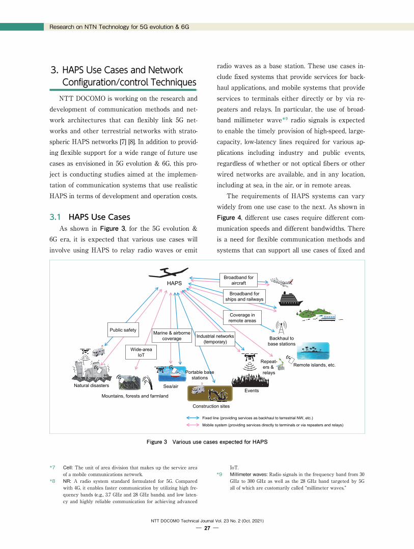
Figure 3 Various use cases expected for HAPS
3. HAPS Use Cases and Network Configuration/control Techniques NTT DOCOMO is working on the research and
development of communication methods and net-work architectures that can flexibly link 5G net-works and other terrestrial networks with strato-spheric HAPS networks [7] [8]. In addition to provid-ing flexible support for a wide range of future use cases as envisioned in 5G evolution & 6G, this pro-ject is conducting studies aimed at the implemen-tation of communication systems that use realistic HAPS in terms of development and operation costs.
3.1 HAPS Use Cases As shown in Figure 3, for the 5G evolution &
6G era, it is expected that various use cases will involve using HAPS to relay radio waves or emit
radio waves as a base station. These use cases in-clude fixed systems that provide services for back-haul applications, and mobile systems that provide services to terminals either directly or by via re-peaters and relays. In particular, the use of broad-band millimeter wave*9 radio signals is expected to enable the timely provision of high-speed, large-capacity, low-latency lines required for various ap-plications including industry and public events, regardless of whether or not optical fibers or other wired networks are available, and in any location, including at sea, in the air, or in remote areas. The requirements of HAPS systems can vary
widely from one use case to the next. As shown in Figure 4, different use cases require different com-munication speeds and different bandwidths. There is a need for flexible communication methods and systems that can support all use cases of fixed and
Fixed line (providing services as backhaul to terrestrial NW, etc.)
Mobile system (providing services directly to terminals or via repeaters and relays)
HAPS
Events
Backhaul to base stations
Remote islands, etc.
Construction sites
Coverage in remote areas
Repeat-ers & relays
Broadband for aircraft
Broadband for ships and railways
Mountains, forests and farmland
Industrial networks (temporary)
Marine & airborne coverage
Wide-area IoT
Public safety
Natural disasters
Portable base stations
Sea/air
*7 Cell: The unit of area division that makes up the service areaof a mobile communications network.
*8 NR: A radio system standard formulated for 5G. Comparedwith 4G, it enables faster communication by utilizing high fre-quency bands (e.g., 3.7 GHz and 28 GHz bands), and low laten-cy and highly reliable communication for achieving advanced
IoT. *9 Millimeter waves: Radio signals in the frequency band from 30
GHz to 300 GHz as well as the 28 GHz band targeted by 5Gall of which are customarily called “millimeter waves.”
NTT
DO
CO
MO
Tec
hnic
al J
ourn
al

Research on NTN Technology for 5G evolution & 6G
NTT DOCOMO Technical Journal Vol. 23 No. 2 (Oct. 2021)
― 28 ―
Figure 4 Requirements for each HAPS use case
mobile systems. For example, it is considered that the commu-
nication speed for backhaul applications to 5G base stations will have to be at least 1 Gbps per service link*10. Furthermore, to provide multiple simulta-neous service links, the feeder link*11 will have to be capable of even faster communications speeds (several Gbps to several tens of Gbps) and must operate as stably as possible regardless of weath-er-related effects. It is also necessary to flexibly control lines so
that they can be adapted from normal business applications to public safety*12 applications in the event of a disaster. Current disaster countermeas-ures are geared towards providing basic commu-nication services such as voice calls and SMS, but in the future, it may also be necessary to consider use cases that require faster communication speeds, such as remote control of equipment at disaster sites, video transmission, and communication via
drones. For disaster countermeasures, it will also be necessary to study network configurations and control techniques that assume the ability of a sys-tem to operate even if some devices become una-vailable.
3.2 Technology for Network Configuration and Control in Conjunction with 5G Networks
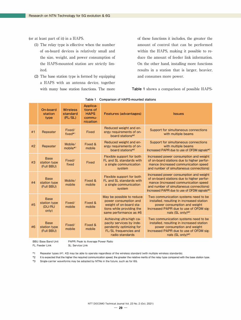
1) Classification of HAPS - mounted Stations In the network configuration and control tech-
nology used when implementing backhauls to 5G base stations via HAPS, we are focusing on the categorization of HAPS-mounted stations. They can be roughly divided into two types: (1) relay stations, which receive signals from ground stations and re-lay them back to other ground stations after per-forming necessary processes such as frequency conversion, and (2) base stations, which are made by installing 5G network base station equipment
Preferably uses flexible communication methods and systems that can handle all fixed and mobile use cases
Gbps class
Mbps class
~1 Gbps
~10 Gbps
~100 Mbps
~10 Mbps
GHz class bandwidth
100 MHz class bandwidth
10 MHz class bandwidth
Broadband for aircraft
Broadband for ships and railways
Industrial networks (temporary)
Wide-area IoTDisaster
countermeasures
Marine & airborne coverage
Coverage in remote areas
Com
mun
icat
ion
spee
d
*10 Service link: A communication path between a satellite orHAPS and a terminal in an NTN communication system.
*11 Feeder Link: A communication path between a satellite orHAPS and a terrestrial base station (gateway) in an NTNcommunication system.
*12 Public safety: A generic term for services that ensure the safety
of the public, including disaster prevention, police, fire, and first-aid services.
NTT
DO
CO
MO
Tec
hnic
al J
ourn
al
Research on NTN Technology for 5G evolution & 6G
NTT DOCOMO Technical Journal Vol. 23 No. 2 (Oct. 2021)
― 29 ―
Table 1 Comparison of HAPS-mounted stations
On-board station type
Wireless standard (FL/SL)
Applica-tions of HAPS commu-nication
Features (advantages) Issues
#1 Repeater Fixed/ fixed*1 Fixed
Reduced weight and en-ergy requirements of on-
board stations*2
Support for simultaneous connections with multiple beams
#2 Repeater Mobile/ mobile*1
Fixed & mobile
Reduced weight and en-ergy requirements of on-
board stations*2
Support for simultaneous connections with multiple beams
Increased PAPR due to use of OFDM signals*3
#3 Base
station type (Full BBU)
Fixed/ fixed Fixed
Flexible support for both FL and SL standards with a single communication
system
Increased power consumption and weight of on-board stations due to higher perfor-mance (increased communication speed and number of simultaneous connections)
#4 Base
station type (Full BBU)
Mobile/ mobile
Fixed & mobile
Flexible support for both FL and SL standards with a single communication
system
Increased power consumption and weight of on-board stations due to higher perfor-mance (increased communication speed and number of simultaneous connections) Increased PAPR due to use of OFDM signals*3
#5
Base station type (DU/RU only)
Fixed/ mobile
Fixed & mobile
May be possible to reduce power consumption and weight of on-board sta-tions while providing the same performance as #6
Two communication systems need to be installed, resulting in increased station power consumption and weight
Increased PAPR due to use of OFDM sig-nals (SL only)*3
#6 Base
station type (Full BBU)
Fixed/ mobile
Fixed & mobile
Achieving ultra-high ca-pacity services by inde-pendently optimizing for FL/SL frequencies and radio standards
Two communication systems need to be installed, resulting in increased station power consumption and weight
Increased PAPR due to use of OFDM sig-nals (SL only)*3
BBU: Base Band Unit PAPR: Peak to Average Power Ratio FL: Feeder Link SL: Service Link *1 Repeater types (#1, #2) may be able to operate regardless of the wireless standard (with multiple wireless standards). *2 It is expected that the higher the required communication speed, the greater the relative merits of the relay type compared with the base station type. *3 Single-carrier waveforms may be adopted by NTNs in the future, such as for 6G.
(or at least part of it) in a HAPS. (1) The relay type is effective when the number of on-board devices is relatively small and the size, weight, and power consumption of the HAPS-mounted station are strictly lim-ited.
(2) The base station type is formed by equipping a HAPS with an antenna device, together with many base station functions. The more
of these functions it includes, the greater the amount of control that can be performed within the HAPS, making it possible to re-duce the amount of feeder link information. On the other hand, installing more functions results in a station that is larger, heavier, and consumes more power.
Table 1 shows a comparison of possible HAPS-
NTT
DO
CO
MO
Tec
hnic
al J
ourn
al

Research on NTN Technology for 5G evolution & 6G
NTT DOCOMO Technical Journal Vol. 23 No. 2 (Oct. 2021)
― 30 ―
Figure 5 Example of cooperative configuration when HAPS is used for backhaul
mounted station configurations. In general, imple-menting more of the base station functions on the ground network side has the advantages of lower development costs and ease of operation, but im-plementing these functions on the HAPS results in greater resilience to natural disasters. In terms of performance, a HAPS-mounted station should at least implement some functions, such as beam control when using millimeter waves. It is also nec-essary to comprehensively study a wide range of requirements to be considered when incorporat-ing HAPS systems into a 5G network. These in-clude the size, weight, and power consumption of HAPS-equipped stations, their development and operation costs, the ability of these HAPS platforms can be shared by fixed-line and mobile communi-cations systems, and their ability to cooperate with GEO/LEO satellites.
2) Examples of Network Configuration in Conjunc-tion with the 5G Network An example of a HAPS base station in a net-
work configuration linked to the 5G network is shown in Figure 5. Here, the Distributed Unit (DU)*13 and Radio Unit (RU)*14 of the 5G base sta-tion are mounted on the HAPS in accordance with Open RAN (O-RAN)*15 Alliance specifications [9]. In this configuration, availability is ensured by in-stalling a Centralized Unit (CU)*16 at a disaster-resistant point on the ground. Information received by the HAPS from the CU in the feeder link is transmitted via 5G radio to a small terrestrial base station device (relay station) in the service link, there-by enabling the use of portable 5G base stations without having to use a wired backhaul. In this configuration, it is also possible to provide direct communication from the HAPS to 5G terminals
5G wirelessCUEPC
Core buildings, etc.
Core network Base station equipment
Disaster-resistant locations where base stations can be
installed*.
HAPS
Small base station equipment (relay station)
CU
Base station equipment mounted
on HAPS
Repeateror IAB
5G wireless
Backhaul
Site diversity (for bad weather and as a disaster countermeasure)
This configuration can also support
terminals directly.*Stoppages caused by disasters are rare
O-DU O-RU
*13 DU: A functional unit of a wireless base station that performsreal-time data link layer control and other functions.
*14 RU: The radio unit of a wireless base station. *15 O-RAN: An open, intelligent radio access network aimed at ef-
ficiently providing a variety of services in the 5G era. *16 CU: An aggregating node that implements functions such as
non-real-time L2 (Layer 2) functions and RRC (radio resourcecontrol) functions in a radio base station.
NTT
DO
CO
MO
Tec
hnic
al J
ourn
al
Research on NTN Technology for 5G evolution & 6G
NTT DOCOMO Technical Journal Vol. 23 No. 2 (Oct. 2021)
― 31 ―
without the need for intervening relay stations. As a further extension, site diversity*17 can be imple-mented by using multiple CUs on the ground side to reduce the impact of bad weather and natural disasters, and mobility support*18 can be implement-ed by switching the communication target to a dif-ferent HAPS when the terminal moves from one communication area to another. In addition to the configuration shown in Fig. 5,
we are also considering other promising configu-rations: one in which a HAPS is used to carry a standalone*19 5G base station, and another with a relay-type configuration where a 5G radio repeat-er is installed in a HAPS. For each configuration, it is necessary to conduct a comprehensive study that takes account of various attributes such as mo-bility support, site diversity technology and frequen-cy sharing technology*20, as well as HAPS instal-lation requirements such as links with GEO/LEO satellites, the equipment weight and power con-sumption.
4. Experimental 39 GHz Band Propagation Measurements Using a Small Aircraft To implement a communication area from an
airborne station in 5G evolution & 6G, we con-ducted an experimental demonstration of radio wave propagation measurements in an urban area (Odawara City, Kanagawa Prefecture), a mountain forest (Tanzawa), and a remote island (Izu Oshima) using a small aircraft (February 15‒26, 2021) [10]. Before using the actual HAPS system, we performed an initial experiment to compare the propagation of millimeter wave (39 GHz band) radio signals,
which are suitable for 5G high-speed communication, and signals at a lower frequency (2 GHz band), which propagate more easily than millimeter wave signals. These signals were sent from the ground to a receiver mounted on a small aircraft about 3 km above ground level. In the urban environment, we measured the effects of obstacles such as build-ings and reflected waves. In the forest, we meas-ured the effects of terrain and trees. And in the remote island, we measured the effects of clouds and low elevation angles above the sea. Our results show that radio wave propagation in the 39 GHz and 2 GHz bands depends on various environmen-tal factors, and changes when the airplane turns.
4.1 Measurement Environment and Measured Items
Figure 6 shows an illustration of the airborne propagation measurement test. The radio wave transmission points were located in an urban area (Odawara City in Kanagawa Prefecture), a forest (Tanzawa), and a remote island (Izu Oshima), and the reception point was a small aircraft circling with a radius of 1 to 2 km. The elevation angle of the small aircraft (receiving point) from the trans-mitting point was determined to be equivalent to the use case of a HAPS circling at an altitude of 20 km. Specifically, we assumed a coverage radius of 50 km for an altitude of 20 km in the urban and forest use cases (elevation angle: 21.8°), and a cov-erage radius of 200 km for an altitude of 20 km in the remote island use case (elevation angle: 5.7‒11.5°). In addition to the line-of-sight environment, we also measured the received power with inter-vening obstacles such as buildings and trees in each use case, as shown in Figure 7.
*17 Site diversity: A technique for improving communication qual-ity by switching between multiple ground stations when radiowaves are highly attenuated due to rain or obstacles.
*18 Mobility support: Technology that allows communication tocontinue when a terminal moves across a communication areaby switching it to a different base station before communica-
tion is interrupted. *19 Standalone: A deployment scenario using only NR, in contrast
with non-standalone operation which uses LTE-NR DC to co-ordinate existing LTE/LTE-Advanced and NR.
NTT
DO
CO
MO
Tec
hnic
al J
ourn
al

Research on NTN Technology for 5G evolution & 6G
NTT DOCOMO Technical Journal Vol. 23 No. 2 (Oct. 2021)
― 32 ―
Figure 6 Illustration of the airborne propagation measurement test
Figure 7 Test environments with various obstacles
Table 2 lists the main specifications of the ex-perimental equipment. For the transmitting anten-na, we selected a product that was able to cover the turning range of the aircraft within the beam width*21, and we fixed the direction of this anten-na toward the aircraft’s turning center. The receiv-ing antenna was housed in a mounting frame, and a 3-mm-thick polycarbonate radome*22 designed to cause almost no propagation loss*23 was secured
to its base. We also performed an initial experiment in which neither of the transmitting or receiving antennas were provided with tracking functions, and the receiving antenna was fixed directly to the underside of the aircraft.
4.2 Evaluation 1) Overview Table 3 shows the results of measuring the
Altitude: 0.5 – 3.8 km
AircraftReceiver
Transmitter (39 GHz band or 2 GHz band)
Transmission point: Urban area (Odawara City)
Forest (Tanzawa)
Remote island (Izu Oshima)
Elevation angle of transmission point and reception point (center of turning):
・21.8° (Odawara City, Tanzawa)
・5.7 – 11.5° (Izu Oshima)Turning radius: 1.0 – 2.0 km
(a) Buildings in the urban test area (b) Trees in the forest test area
(c) Mountains in the forest test area (d) Clouds in the remote island test area
*20 Frequency sharing technology: Technology that makes it pos-sible to share frequencies by suppressing the interference ef-fects that occur when two systems use the same frequency atthe same location. In this article, we are mostly concernedwith frequency sharing between HAPS systems and terres-trial mobile communication systems.
*21 Beam width: The antenna radiation angle at which the beamis radiated with gain of ‒3dB or less from the maximum an-tenna gain.
*22 Radome: An enclosure to protect an antenna. These are madeof materials that are transparent to radio waves.
NTT
DO
CO
MO
Tec
hnic
al J
ourn
al

Research on NTN Technology for 5G evolution & 6G
NTT DOCOMO Technical Journal Vol. 23 No. 2 (Oct. 2021)
― 33 ―
airborne propagation of radio waves. From this experiment, we found that the maximum recep-tion sensitivity in the unobstructed line-of-sight
environments was almost identical to the value obtained by desktop calculations, while the loss of received power in the 39 GHz band was relatively
Table 2 Main specifications of the airborne propagation test apparatus
Frequency band Main specifications of the test apparatus and equipment
Transmitter
39.75 GHz band
・Maximum transmitter output: 37 dBm ・Transmitted wave type: unmodulated ・Antenna type: horn ・Maximum transmitting antenna gain: 14.6 dBi ・Radio wave emission direction: towards the aircraft’s turning center ・Polarization: vertical
2.2001 GHz band
・Maximum transmitter output: 42 dBm ・Transmitted wave type: unmodulated ・Antenna type: sleeve ・Maximum transmitting antenna gain: 2.2 dBi ・Radio wave emission direction: horizontal ・Polarization: vertical
Receiver 39.75 GHz band ・Antenna type: omni
・Maximum receiving antenna gain: 3.0 dBi
2.2001 GHz band ・Antenna type: omni ・Maximum receiving antenna gain: 0.0 dBi
Table 3 Summary of the airborne radio wave propagation measurement results
39 GHz band measurement environment 39 GHz band measurement results
Everywhere
・The maximum line-of-sight reception sensitivity roughly matches the results of desktop calcu-lations in all environments (within 5 dB of error). ・The predicted average/median was about 14‒24 dB less than the maximum. Fluctuations in the directivity pattern of the transmitting and receiving antennas due to turning, polarization losses, and occlusion by the aircraft itself have a large effect.
For the practical application of HAPS, it will be important to develop control technology that can suppress this sort of turning-related effect and maintain a constant received power.
・The difference between the mean and median was within 2.5 dB except for Tanzawa (mountain), where there was a lot of data buried in the noise floor, and the difference was about 3.8 dB. ・In the 2 GHz band, which was tested by way of comparison, the signals also tended to be at-tenuated due to obstacles and the effects of turning.
Odawara (buildings) ・Compared with the forecast, the average value was approximately 17 dB lower, and the me-dian value was approximately 19 dB lower.
Tanzawa (trees) ・Compared with the forecast, the average value was approximately 18 dB lower, and the me-dian value was approximately 19 dB lower.
Tanzawa (mountains) ・Compared with the forecast, the average value was approximately 30 dB lower, and the me-dian value was approximately 36 dB lower.
Izu Oshima (white clouds)
・Compared with the forecast, the average value was approximately 2 dB higher, and the me-dian value was approximately 4 dB higher. Hardly any cloud attenuation was observed, and it is inferred that flight trajectory errors have a dominant effect.
*23 Propagation loss: The amount of attenuation in the power ofa signal emitted from a transmitting station until it arrives ata reception point.
NTT
DO
CO
MO
Tec
hnic
al J
ourn
al
Research on NTN Technology for 5G evolution & 6G
NTT DOCOMO Technical Journal Vol. 23 No. 2 (Oct. 2021)
― 34 ―
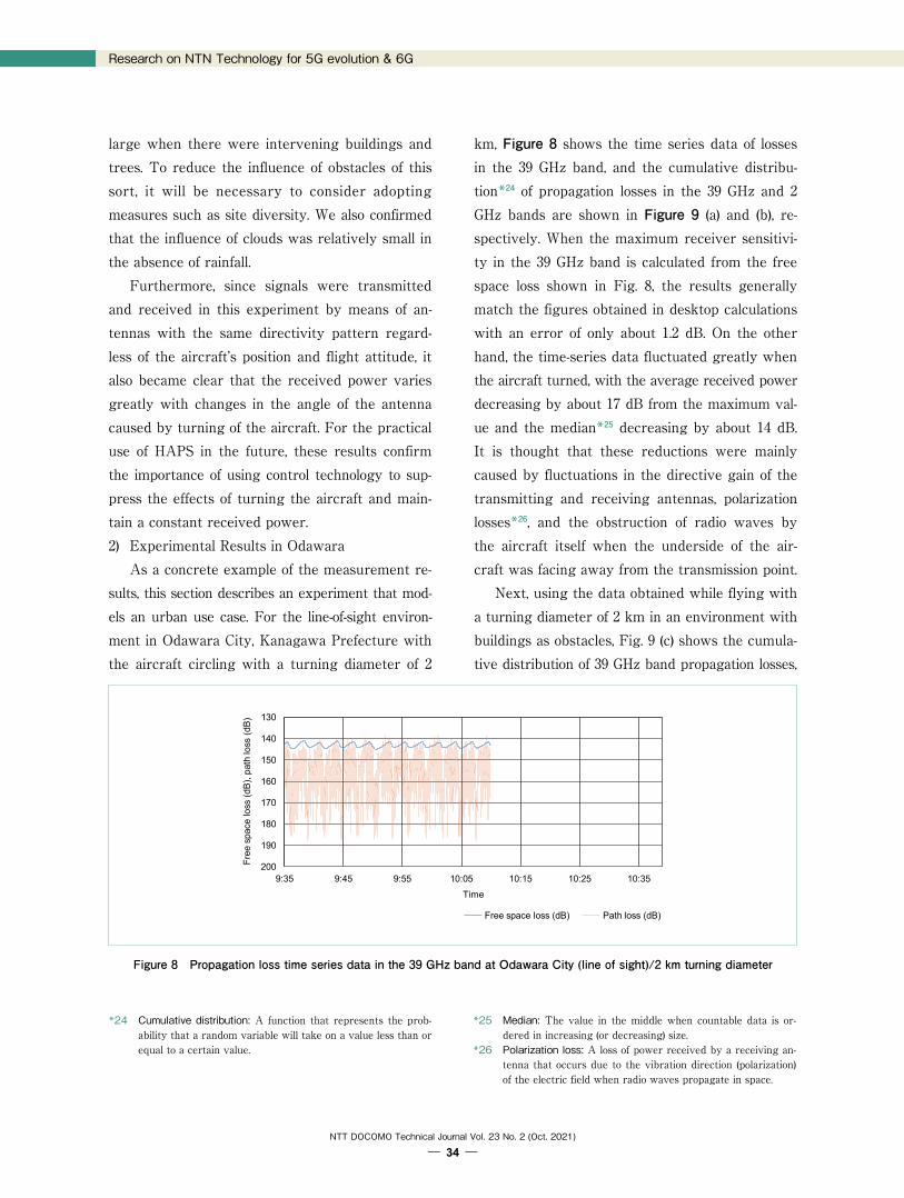
Figure 8 Propagation loss time series data in the 39 GHz band at Odawara City (line of sight)/2 km turning diameter
large when there were intervening buildings and trees. To reduce the influence of obstacles of this sort, it will be necessary to consider adopting measures such as site diversity. We also confirmed that the influence of clouds was relatively small in the absence of rainfall. Furthermore, since signals were transmitted
and received in this experiment by means of an-tennas with the same directivity pattern regard-less of the aircraft’s position and flight attitude, it also became clear that the received power varies greatly with changes in the angle of the antenna caused by turning of the aircraft. For the practical use of HAPS in the future, these results confirm the importance of using control technology to sup-press the effects of turning the aircraft and main-tain a constant received power. 2) Experimental Results in Odawara As a concrete example of the measurement re-
sults, this section describes an experiment that mod-els an urban use case. For the line-of-sight environ-ment in Odawara City, Kanagawa Prefecture with the aircraft circling with a turning diameter of 2
km, Figure 8 shows the time series data of losses in the 39 GHz band, and the cumulative distribu-tion*24 of propagation losses in the 39 GHz and 2 GHz bands are shown in Figure 9 (a) and (b), re-spectively. When the maximum receiver sensitivi-ty in the 39 GHz band is calculated from the free space loss shown in Fig. 8, the results generally match the figures obtained in desktop calculations with an error of only about 1.2 dB. On the other hand, the time-series data fluctuated greatly when the aircraft turned, with the average received power decreasing by about 17 dB from the maximum val-ue and the median*25 decreasing by about 14 dB. It is thought that these reductions were mainly caused by fluctuations in the directive gain of the transmitting and receiving antennas, polarization losses*26, and the obstruction of radio waves by the aircraft itself when the underside of the air-craft was facing away from the transmission point. Next, using the data obtained while flying with
a turning diameter of 2 km in an environment with buildings as obstacles, Fig. 9 (c) shows the cumula-tive distribution of 39 GHz band propagation losses,
130
140
150
160
170
180
190
2009時35分 9時45分 9時55分 10時05分 10時15分 10時25分 10時35分
自由空間
損失(
dB)、
パスロス
(dB
)
時刻
自由空間損失(dB) パスロス(dB)
Fre
e sp
ace
loss
(dB
), p
ath
loss
(dB
)
9:35 9:45 9:55 10:05 10:15 10:25 10:35
Time
Free space loss (dB) Path loss (dB)
*24 Cumulative distribution: A function that represents the prob-ability that a random variable will take on a value less than orequal to a certain value.
*25 Median: The value in the middle when countable data is or-dered in increasing (or decreasing) size.
*26 Polarization loss: A loss of power received by a receiving an-tenna that occurs due to the vibration direction (polarization)of the electric field when radio waves propagate in space.
NTT
DO
CO
MO
Tec
hnic
al J
ourn
al

Research on NTN Technology for 5G evolution & 6G
NTT DOCOMO Technical Journal Vol. 23 No. 2 (Oct. 2021)
― 35 ―
Figure 9 Cumulative distribution of propagation loss in Odawara City with a 2 km turning diameter
Fig. 9 (d) shows the cumulative distribution of 2 GHz band propagation losses, and Figure 10 shows a map of propagation losses in the 39 GHz band. Comparing the mean and median values of Fig. 9 (a) and (c), the 39 GHz propagation loss has a mean value about 17 dB larger and a median value about 19 dB larger in the building-occluded environment compared with the line-of-sight environment. By comparing the average and median values of Fig. 9 (b) and (d), it can be seen that although obstruc-tion by buildings also affects the 2 GHz band, the losses are relatively small ‒ about 8 dB in the av-erage value and about 9 dB in the median value ‒
compared with the line-of-sight environment. Fur-thermore, from Fig. 10, it can be seen that when the underside of the aircraft is tilted towards the transmitting point, the received power is at least 40 dB greater than when the aircraft is tilted in the other direction.
5. Conclusion In this article, as part of our efforts towards
implementing extreme coverage extension, which is one of the important issues for 5G evolution & 6G, we have described NTN technology, especially
(a) Cumulative propagation loss distribution in the 39 GHz band line-of-sight environment
0%
10%
20%
30%
40%
50%
60%
70%
80%
90%
100%
0
1,000
2,000
3,000
4,000
5,000
6,000
7,000
8,000
9,000
10,000
11,000
12,000
13,000
140 145 150 155 160 165 170 175 180 185 190 195
頻度
Path loss (dB)
0%
10%
20%
30%
40%
50%
60%
70%
80%
90%
100%
0
2,000
4,000
6,000
8,000
10,000
12,000
14,000
16,000
18,000
20,000
22,000
24,000
26,000
140 145 150 155 160 165 170 175 180 185 190 195
頻度
Path loss (dB)
0%
10%
20%
30%
40%
50%
60%
70%
80%
90%
100%
0
3,000
6,000
9,000
12,000
15,000
18,000
21,000
115 120 125 130 135 140 145 150 155 160
頻度
Path loss (dB)
0%
10%
20%
30%
40%
50%
60%
70%
80%
90%
100%
0
1,000
2,000
3,000
4,000
5,000
6,000
7,000
8,000
9,000
10,000
11,000
12,000
13,000
115 120 125 130 135 140 145 150 155 160 165
頻度
Path loss (dB) 頻度 累積%
(b) Cumulative propagation loss distribution in the 2 GHz band line-of-sight environment
(c) Cumulative propagation loss distribution in the 39 GHz band building-obstructed environment
(d) Cumulative propagation loss distribution in the 2 GHz band building-obstructed environment
Fre
quen
cyF
requ
ency
Fre
quen
cyF
requ
ency
Frequency Cumulative %
NTT
DO
CO
MO
Tec
hnic
al J
ourn
al

Research on NTN Technology for 5G evolution & 6G
NTT DOCOMO Technical Journal Vol. 23 No. 2 (Oct. 2021)
― 36 ―
Figure 10 Map of propagation losses in the 39 GHz band at Odawara City (buildings)/2 km turning diameter
HAPS use cases and network configuration/control technology, and we have shown the results of air-borne radio propagation tests performed using a small aircraft assuming HAPS use cases. NTT DOCOMO will continue developing NTN technology aimed at achieving extreme coverage extension and tech-nology for realizing HAPS networks, and promot-ing demonstration experiments and standardiza-tion activities. Finally, part of this research and development
is carried out by the Ministry of Internal Affairs and Communications (Research and Development for Expansion of Radio Resources; JPJ000254).
REFERENCES [1] NTT DOCOMO: “White Paper: 5G evolution and 6G,”
Feb. 2021. https://www.nttdocomo.co.jp/english/binary/pdf/corporate/technology/whitepaper_6g/DOCOMO_6G_White_PaperEN_v3.0.pdf
[2] T. Onizawa, T. Tatsuta, N. Kita and F. Yamashita:
“Recent Research and Development in Fixed Wireless and Satellite Communication Systems,” IEICE Technical Report, RCS2019-32, pp.53‒58, May 2019.
[3] J. Bejarano, C. Nieto and F. Piñar: “MF-TDMA Sched-uling Algorithm for Multi-Spot Beam Satellite Systems Based on Co-Channel Interference Evaluation,” IEEE Access, Vol.7, pp.4391‒4399, Dec. 2018.
[4] B. Di, H. Zhang, L. Song, Y. Li and G.Y. Li: “Ultra-dense LEO: integrating terrestrial-satellite networks into 5G and beyond for data offloading,” IEEE Transactions on Wireless Communications, Vol.18, Issue 1, pp.47‒62, Dec. 2018.
[5] HAPS Alliance: “Introducing the HAPS Alliance.” https://hapsalliance.org/
[6] 3GPP, RP-193234: “Solutions for NR to support non-terrestrial networks (NTN),” Dec. 2019.
[7] J. Suzuki, N. Kitanosono, T. Takamori, Y. Morita, Y. Kishiyama, T. Toyama and R. Miura: “Development of a 38-GHz band wireless communication system with high-altitude platform stations (HAPS) in cooperation with 5G networks: A study of high-speed high-capacity backhaul lines for 5G networks,” Proc. 2021 IEICE Gen-eral Conference, B-3-1, Mar. 2021.
[8] Y. Tonozono, Y. Kishiyama, T. Asai, J. Suzuki and N.
Transmission point
Path loss (dB)
©2021 Google – Map data ©2021 Google, ZENRIN
Map of path losses corresponding to turning of the aircraft (2 km diameter)
NTT
DO
CO
MO
Tec
hnic
al J
ourn
al

Research on NTN Technology for 5G evolution & 6G
NTT DOCOMO Technical Journal Vol. 23 No. 2 (Oct. 2021)
― 37 ―
Kitanosono: “Development of a 38-GHz band wireless communication system with high-altitude platform sta-tions (HAPS) in cooperation with 5G networks: A study of HAPS network configuration and control technolo-gy,” Proc. 2021 IEICE General Conference, B-3-2, Mar. 2021.
[9] A. Umesh et al.: “Overview of O-RAN Fronthaul Spec-ifications,” NTT DOCOMO Technical Journal, Vol.21, No.1, pp.46‒59, Jul. 2019.
[10] NTT DOCOMO Press Release: “Trial measurements of 39 GHz band radio propagation with a view to serving communication areas with airborne systems,” Mar. 2021.
NTT
DO
CO
MO
Tec
hnic
al J
ourn
al