special equipment and compressors for underwater ... · pdf filespecial equipment and...
TRANSCRIPT

Revision: DOC MCH 13-16-26-32/ET-04-00
INSTRUCTION
MANUAL
VERSION: English
Special equipment and compressors for underwater activities
H i g h P r e s s u r e C o m p r e s s o r sH i g h P r e s s u r e C o m p r e s s o r s

2
GUGUGUGUGUARANTEE ARANTEE ARANTEE ARANTEE ARANTEE AND AND AND AND AND ASSISTASSISTASSISTASSISTASSISTANCEANCEANCEANCEANCE
1.1 Guarantee ............................................................................................................................ 8
1.2 Assistance ........................................................................................................................... 8
11111
22222
USE IN BRIEFUSE IN BRIEFUSE IN BRIEFUSE IN BRIEFUSE IN BRIEF
TECHNICAL DESCRIPTIONTECHNICAL DESCRIPTIONTECHNICAL DESCRIPTIONTECHNICAL DESCRIPTIONTECHNICAL DESCRIPTION
2.1 Operating principle ............................................................................................................... 10
2.2 Description of the pump unit ................................................................................................. 11
2.2.1 Monobloc unit ............................................................................................................. 12
2.2.2 Head unit ................................................................................................................ .... 13
2.2.3 Safety valves ............................................................................................................... 13
2.2.4 Lubricating unit ............................................................................................................ 14
2.2.5 Pressure maintenance valve ........................................................................................ 14
2.2.6 Cooling pipes .............................................................................................................. 14
2.2.7 Filters .......................................................................................................................... 15
2.2.8 Frame and sound-proofed casing ................................................................................. 16
2.3 Machine control ................................................................................................................... 16
33333 TECHNICAL CHARACTERISTICTECHNICAL CHARACTERISTICTECHNICAL CHARACTERISTICTECHNICAL CHARACTERISTICTECHNICAL CHARACTERISTIC
3.1 Technical characteristics of the pump unit ............................................................................ 18
3.1.1 Machine series MCH 13-16-26-32/ET .......................................................................... 18
3.1.2 Sizes and weights ....................................................................................................... 19
3.2 Noise ................................................................................................................................... 19
44444 PRECAPRECAPRECAPRECAPRECAUTIONS FOR USE UTIONS FOR USE UTIONS FOR USE UTIONS FOR USE UTIONS FOR USE AND MAINTENAND MAINTENAND MAINTENAND MAINTENAND MAINTENANCEANCEANCEANCEANCE
4.1 Machine area diagrams ........................................................................................................ 21
4.1.1 Safety devices ............................................................................................................. 22
4.1.2 Residual risk areas ..................................................................................................... 24
Use in brief ................................................................................................................... .................. 7
Index

3Index
55555UNPUNPUNPUNPUNPAAAAACKING CKING CKING CKING CKING AND HANDLING AND HANDLING AND HANDLING AND HANDLING AND HANDLING THE MATHE MATHE MATHE MATHE MACHINECHINECHINECHINECHINE
5.1 Unpacking the machine ........................................................................................................ 25
5.2 Pack contents...................................................................................................................... 26
5.3 Handling the machine ........................................................................................................... 26
66666INSTINSTINSTINSTINSTALLAALLAALLAALLAALLATIONTIONTIONTIONTION
6.1 Positioning ........................................................................................................................... 27
6.2 Connections ......................................................................................................................... 28
6.2.1 Connecting the extension for the air intake................................................................... 28
6.2.2 Connecting the refill hoses .......................................................................................... 32
6.2.3 Electrical connections ................................................................................................. 33
CONTRCONTRCONTRCONTRCONTROL POL POL POL POL PANELANELANELANELANEL
7.1 Control panel ........................................................................................................................ 34
7.2 Indication and control devices .............................................................................................. 35
77777
STSTSTSTSTARARARARART UPT UPT UPT UPT UP
8.1 Filling the machine ............................................................................................................... 36
8.2 Checks ................................................................................................................................ 37
88888
USUSUSUSUSEEEEE
9.1 Preliminary operations ......................................................................................................... 40
9.2 Refilling the cylinders ........................................................................................................... 43
99999
4
1010101010 PUTTING PUTTING PUTTING PUTTING PUTTING THE MATHE MATHE MATHE MATHE MACHINE OUT OF OPERACHINE OUT OF OPERACHINE OUT OF OPERACHINE OUT OF OPERACHINE OUT OF OPERATIONTIONTIONTIONTIONAND DISMANTLING THE MACHINEAND DISMANTLING THE MACHINEAND DISMANTLING THE MACHINEAND DISMANTLING THE MACHINEAND DISMANTLING THE MACHINE
10.1 Instructions for prolonged machine standstills ...................................................................... 46
10.2 Disposal of waste products .................................................................................................. 46
10.3 Dismantling the machine ...................................................................................................... 47
MAINTENANCEMAINTENANCEMAINTENANCEMAINTENANCEMAINTENANCE
11.1 General notes ...................................................................................................................... 48
11.2 Preventive maintenance ........................................................................................................ 49
11.3 Changing the lubricant oil ..................................................................................................... 50
11.4 Checking the transmission belt ............................................................................................ 51
11.5 Air intake filter ...................................................................................................................... 53
11.6 Active carbon filter and molecular sieve ................................................................................ 55
11.7 Refil hose ............................................................................................................................. 57
11.8 Intake and discharge valves .................................................................................................. 58
11.9 Heads .................................................................................................................................. 58
11.10 Cylinders .............................................................................................................................. 59
11.11 Maintenance programme ...................................................................................................... 60
1111111111
TRTRTRTRTROUBLESHOOOUBLESHOOOUBLESHOOOUBLESHOOOUBLESHOOTINGTINGTINGTINGTING
12.1 List of faults ......................................................................................................................... 62
1212121212
MACHINE DIAGRAMSMACHINE DIAGRAMSMACHINE DIAGRAMSMACHINE DIAGRAMSMACHINE DIAGRAMS
13.1 Compression diagram .......................................................................................................... 63
13.2 Electrical diagram ................................................................................................................ 64
1313131313
Index

5
SPSPSPSPSPARE PARE PARE PARE PARE PARARARARARTSTSTSTSTS
14.1 Exploded view of the machine parts .................................................................................. 69
Monobloc .......................................................................................................................... 70
Pistons rod unit ................................................................................................................. 72
Cylinders unit .................................................................................................................... 74
Head unit .......................................................................................................................... 76
Cooling pipes .................................................................................................................... 78
Filtering system ................................................................................................................ 80
MCH 13-16/ET condensate trap ........................................................................................ 82
MCH 26-32/ET condensate trap ........................................................................................ 84
MCH 13-16/ET .................................................................................................................. 86
MCH 26-32/ET .................................................................................................................. 88
MCH 26-32/ET front panel ................................................................................................. 90
1414141414
Index

6
To make the manual easier to read, the following terms have been adopted:
DANGER
The term DANGER is used when failure to comply with the regulations or tampering with theparts could lead to serious injury or even death.
WARNING
The term WARNING is used when failure to comply with the instructions could cause damage to themachine and other parts associated with the same or to the surrounding area.
LABEL APPLIED TO THE COMPRESSORS
To protect exposed persons or objects, a special booklet entitled “SAFETY REGULATIONS” is suppliedwith the machine and must be considered an integral part of the Compressor Instruction Manual.
This manual is the property of AEROTECNICA COLTRI S.r.l. and any copying of the same, even partial, isprohibited.
Use in brief
7
The following information must be referred to and applied only when this manual and the“Safety regulations” manual have been read and their contents have been understood andassimilated.
- Check whether or not the area where the machine is installed has suitable ventilation(see chapter 6.1).
- If the machine is installed in a place without the required characteristics above, connect the air intakeextension (see chapter 6.2.1).
- Connect the refill hoses to the machine (see chapter 6.2.2).
- Connect the switchboard to the mains power supply (see chapter 6.2.3).
- Check the level of the lubricating oil in the pump unit (see chapter 8.2). If the level is too low, turn offthe machine and add or change the oil (see chapter 8.1).
- Turn on the machine using the main switch (see chapter 7.1).
- Check the direction of rotation of the motor. If the direction of rotation does not coincide with the oneshown on the belt guard, turn off the machine and invert the two phases on the main power supply(see chapter 7.2).
- Check the operation of the safety valve (see chapter 9.1).
- Check for wear on the cylinders to be filled (see chapter 9.1).
- Set the pressure switch on the control panel to the refill pressure value given on the cylinder(see chapter 8.1).
- Fit the hose attachment on the cylinder and check that the taps on the hose are open(see chapter 9.2).
- Turn on the cylinder tap and start up the compressor (see chapter 9.2).
- When the filling operation has been completed, the compressor is stopped automatically by thepressure switch, turn off the cylinder and the hose taps.
- Press the pressure bleed button and disconnect the cylinder attachment (see chapter 9.2).
USE IN BRIEFUSE IN BRIEFUSE IN BRIEFUSE IN BRIEFUSE IN BRIEF
Use in brief

GUGUGUGUGUARANTEE ARANTEE ARANTEE ARANTEE ARANTEE AND AND AND AND AND ASSISTASSISTASSISTASSISTASSISTANCEANCEANCEANCEANCE11111
AEROTECNICA COLTRI S.r.l. guarantees its compressors against any design or manufacturing defector fault and against any fault in the materials for a period of twelve months from the delivery of themachine. The customer must inform AEROTECNICA COLTRI S.r.l. in writing of any fault and/or defectthat may be found within eight days from its discovery by means of a registered letter with advice ofreceipt or telegramme, otherwise the guarantee will become null and void.
The guarantee is only valid against faults or defects that may arise with the compressor used underproper operating conditions according to the instructions given in this manual and with the maintenancecarried out at the intervals as provided for.
The guarantee expressly excludes any faults arising as a result of improper use of the machine, ofatmospheric agents and of damage due to transport; the guarantee does not cover the expendablematerials and materials required for the periodic maintenance which are at the customer’s entireexpense. The guarantee will, in any case, become automatically null and void if the compressor istampered with or if it has been serviced by technicians who are not authorized to do so byAEROTECNICA COLTRI S.r.l.
Any compressor that is acknowledged to be faulty due to defects in the design, manufacturing or materialsused, will be repaired or replaced free of charge by AEROTECNICA COLTRI S.r.l. at its factory in SanMartino della Battaglia (BRESCIA). The customer will be responsible for the costs of transport andcarriage as well as for any spare parts and expendable materials.
If it should be necessary for service to be carried out under the guarantee at the customer’s premises,the latter will be responsible for the travel and transfer costs for the staff sent out byAEROTECNICA COLTRI S.r.l.
Taking delivery of the machine and/or of any faulty components or the transfers for the inspection offaults and/or defects as notified by the customer, will not, however, denote any implicit acknowledgementregarding the effectiveness of the guarantee.
Repairs and/or replacements made by AEROTECNICA COLTRI S.r.l. during the guarantee period willnot extend the duration of the same.
Acknowledgment of the guarantee does not itself imply any liability for compensation on the part ofAEROTECNICA COLTRI S.r.l.
AEROTECNICA COLTRI S.r.l. does not assume any responsibility for injury to persons or damage toproperty or for any other direct or indirect damage (loss of production or missed profit, etc.) that may beattributable to faults or defects of the compressor, except for those cases in which a serious fault can beattributed to the company.
1.11.11.11.11.1 Guarantee
8
1.21.21.21.21.2 Assistance Assistance Assistance Assistance Assistance
The AEROTECNICA COLTRI S.r.l. technicians are available for any kind of routine or additionalmaintenance work.
The request for technical assistance must be sent to AEROTECNICA COLTRI S.r.l. at the followingaddress:
AEROTECNICA COLTRI S.r.l.
Via Colli Storici, 17725010 San Martino della Battaglia (BRESCIA) ITALIA
Fax: +39 030 9910283e-mail: [email protected]
Guarantee and assistance
9
This chapter provides a technological description of the machine and its main components.
2.1 Operating principle ......................................................................................................... .. 10
2.2 Description of the pump unit ............................................................................................ 11
2.2.1 Monobloc unit .......................................................................................................... 12
2.2.2 Head unit .................................................................................................................. 13
2.2.3 Safety valves ............................................................................................................. 13
2.2.4 Lubrication unit ........................................................................................................ 1 4
2.2.5 Pressure maintenance valve .................................................................................... 14
2.2.6 Cooling pipes ........................................................................................................... 1 4
2.2.7 Filters ........................................................................................................................ 15
2.2.8 Frame and sound-proofed casing ............................................................................ 16
2.3 Machine control ................................................................................................................ 16
TECHNICAL DESCRIPTIONTECHNICAL DESCRIPTIONTECHNICAL DESCRIPTIONTECHNICAL DESCRIPTIONTECHNICAL DESCRIPTION 22222
Technical description
10
1 2
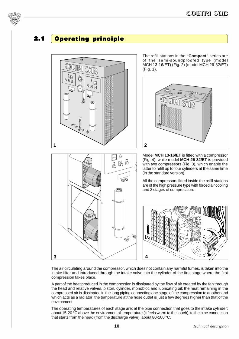
The refill stations in the “Compact” series areof the semi-soundproofed type (modelMCH 13-16/ET) (Fig. 2) (model MCH 26-32/ET)(Fig. 1).
43
The air circulating around the compressor, which does not contain any harmful fumes, is taken into theintake filter and introduced through the intake valve into the cylinder of the first stage where the firstcompression takes place.
A part of the heat produced in the compression is dissipated by the flow of air created by the fan throughthe head and relative valves, piston, cylinder, monobloc and lubricating oil; the heat remaining in thecompressed air is dissipated in the long piping connecting one stage of the compression to another andwhich acts as a radiator; the temperature at the hose outlet is just a few degrees higher than that of theenvironment.
The operating temperatures of each stage are: at the pipe connection that goes to the intake cylinder:about 15-20 °C above the environmental temperature (it feels warm to the touch), to the pipe connectionthat starts from the head (from the discharge valve), about 80-100 °C.
2.12.12.12.12.1 Operating principle Operating principle Operating principle Operating principle Operating principle
Technical description
Model MCH 13-16/ET is fitted with a compressor(Fig. 4), while model MCH 26-32/ET is providedwith two compressors (Fig. 3), which enable thelatter to refill up to four cylinders at the same time(in the standard version).
All the compressors fitted inside the refill stationsare of the high pressure type with forced air coolingand 3 stages of compression.
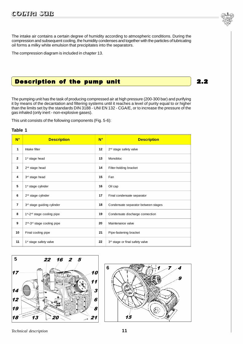
The intake air contains a certain degree of humidity according to atmospheric conditions. During thecompression and subsequent cooling, the humidity condenses and together with the particles of lubricatingoil forms a milky white emulsion that precipitates into the separators.
The compression diagram is included in chapter 13.
11
The pumping unit has the task of producing compressed air at high pressure (200-300 bar) and purifyingit by means of the decantation and filtering systems until it reaches a level of purity equal to or higherthan the limits set by the standards DIN 3188 - UNI EN 132 - CGA/E, or to increase the pressure of thegas inhaled (only inert - non-explosive gases).
This unit consists of the following components (Fig. 5-6):
5
6
Technical description
2.22.22.22.22.2 Description of the pump unit Description of the pump unit Description of the pump unit Description of the pump unit Description of the pump unit
N° Description N° Description
1 Intake filter 12 2nd stage safety valve
2 1st stage head 13 Monobloc
3 2nd stage head 14 Filter-holding bracket
4 3rd stage head 15 Fan
5 1st stage cylinder 16 Oil cap
6 2nd stage cylinder 17 Final condensate separator
7 3rd stage guiding cylinder 18 Condensate separator between stages
8 1st-2nd stage cooling pipe 19 Condensate discharge connection
9 2nd-3rd stage cooling pipe 20 Maintenance valve
10 Final cooling pipe 21 Pipe-fastening bracket
11 1st stage safety valve 22 3rd stage or final safety valve
Table 1

12
The cylinders are made of cast iron (Fig. 9), whilethe pistons are made of aluminium and havetraditional multiple compression rings. The highpressure stage piston has an anti-wear coating.The relative cylinder is given a self-lubricatingtreatment.
9
7
8
Technical description
2.2.12.2.12.2.12.2.12.2.1 Monobloc unit Monobloc unit Monobloc unit Monobloc unit Monobloc unit
The gooseneck, the pistons and the cylindersalso form a part of this unit.
The monobloc (Fig. 7) is made of aluminiumalloy, the two flanges with the ball and rollerbearings that support the gooseneck are oil-tight with the monobloc due to the O-Ringsfitted.
The gooseneck and the connecting rods onlyturn on roller or ball bearings (Fig. 8).
The three connecting rods are fitted on thegooseneck with a single crank angle.

10
The head unit includes the discharge and intakevalves.The head of the 1st stage is of a lamellar type andincludes both the intake and the discharge.The intake and discharge valves are located directlyin their threaded seats of the heads of the 2nd and3rd stages. The intake valves can be removed usingthe special pin wrench (cod. SC000480), havingfirst removed the heads.
The discharge valves can be removed from theoutside.
See Chapter 11, “Maintenance”.
2.2.22.2.22.2.22.2.22.2.2 Head unit (Fig. 10) Head unit (Fig. 10) Head unit (Fig. 10) Head unit (Fig. 10) Head unit (Fig. 10)
13Technical description
The purpose of the safety valves (see figure 5) is to protect the machine (and the cylinders) fromoverpressure.
These valves are pre-calibrated in the factory at the following pressures:- safety valve for 1st stage: 8 bar;- safety valve for 2nd stage: 50 bar;- safety or final valve for 3rd stage: 225 bar - or 330 bar.
WARNING
Under no circumstances may these valves be altered to increase the calibrated pressure.
If these valves should come into operation, check the cause that has led to the maximum pressure andtake steps according to the instructions given in paragraph 12.1.
Any tampering with the safety valves causes serious damage and an immediate cancellation of theguarantee.
2.2.32.2.32.2.32.2.32.2.3 Safety valves Safety valves Safety valves Safety valves Safety valves

2.2.42.2.42.2.42.2.42.2.4
11
Lubricating unit Lubricating unit Lubricating unit Lubricating unit Lubricating unit
Lubrication is carried out by means of a tangscrewed into the end part of the connecting rods ofthe 2nd and 3rd stages (Fig. 11).
The 3rd high pressure stage is lubricated by oilvapours.
This valve is fitted after the final filter. Just a few seconds after the compressor has been started up, itkeeps the pressure of the entire system at 100 ± 20 bar (see exploded view Chapter 14), for the purposeof eliminating as much water as possible from the air. It also acts as a non-return valve.
2.2.52.2.52.2.52.2.52.2.5 Pressure maintenance valve Pressure maintenance valve Pressure maintenance valve Pressure maintenance valve Pressure maintenance valve
14
12
Technical description
2.2.62.2.62.2.62.2.62.2.6 Cooling pipes (Fig. 12) Cooling pipes (Fig. 12) Cooling pipes (Fig. 12) Cooling pipes (Fig. 12) Cooling pipes (Fig. 12)
The cooling pipes between the 1st and 2nd stage,between the 2nd and 3rd stage and after the 3rd stageare made of stainless steel, like those for thepassage of air between the separator and the filter.

15
14
13
Technical description
ACTIVE CARBON AND MOLECULAR SIEVE FILTER (Fig. 14)
For model MCH 13-16/ET, the filter is housed insidethe compressor covering panel, while for modelMCH 26-32/ET there are two active carbon filtersboth of which are located on the outside of thecompressor on the front panel.
The filter consists of an aluminium tube (B) thatholds the filter cartridge (A).
The shell of the cartridge contains the active carbon(C) and the molecular sieve (D) placed betweenfelt disks.
The condition of the cartridge is of fundamentalimportance for the quality of the air (see paragraph11.7 for replacement instructions).
2.2.72.2.72.2.72.2.72.2.7 Filters Filters Filters Filters Filters
INTAKE FILTER (Fig. 13)
The suction filter is coupled directly to the lid ofthe 1st stage head.
The intake filter consists of a cylindrical aluminiumcasing provided with a screw cap that holds thefiltering cartridge.
A special attachment is provided on the filter forthe connection of an extension (optional) whichenables air to be taken from the outside when thecompressor is installed in a place without idealventilation.
For the compressor to operate properly, the filtermaintenance must be carried out as provided forand at the intervals recommended (instructions inparagraph 11.6).
16
15
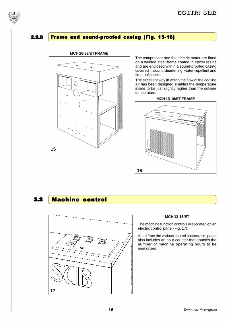
The compressor and the electric motor are fittedon a welded steel frame coated in epoxy resinsand are enclosed within a sound-proofed casingcovered in sound-deadening, water-repellent andfireproof panels.The excellent way in which the flow of the coolingair has been designed enables the temperatureinside to be just slightly higher than the outsidetemperature.
MCH 13-16/ET FRAME
MCH 26-32/ET FRAME
2.2.82.2.82.2.82.2.82.2.8 F F F F Frrrrrame and sound-prame and sound-prame and sound-prame and sound-prame and sound-proofoofoofoofoofed casing (Figed casing (Figed casing (Figed casing (Figed casing (Fig..... 15-16) 15-16) 15-16) 15-16) 15-16)
16
2.32.32.32.32.3 Machine control Machine control Machine control Machine control Machine control
17
MCH 13-16/ET
The machine function controls are located on anelectric control panel (Fig. 17).
Apart from the various control buttons, this panelalso includes an hour counter that enables thenumber of machine operating hours to bememorized.
Technical description
17
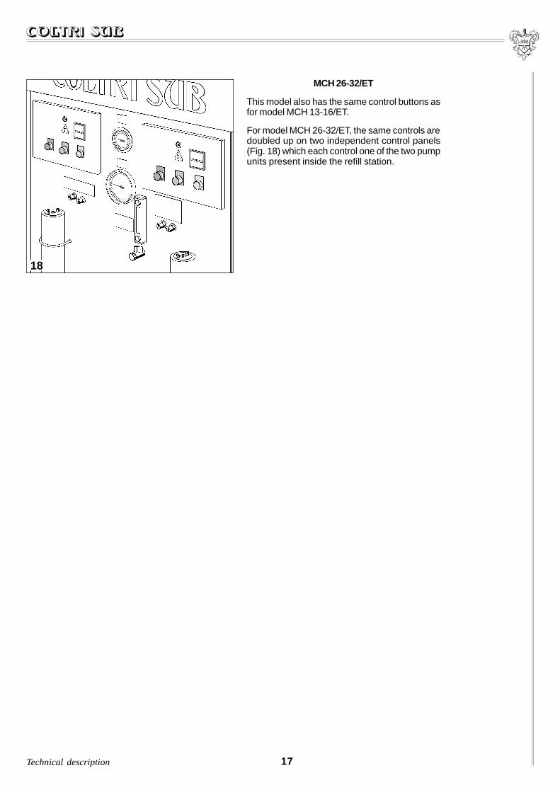
MCH 26-32/ET
This model also has the same control buttons asfor model MCH 13-16/ET.
For model MCH 26-32/ET, the same controls aredoubled up on two independent control panels(Fig. 18) which each control one of the two pumpunits present inside the refill station.
18
Technical description

This chapter provides some technical information concerning the machine.
3.1 Technical characteristics of the pump unit ....................................................................... 18
3.1.1 Machine series MCH 13-16-26-32/ET ......................................................................... 18
3.1.2 Sizes and weights ..................................................................................................... 19
3.2 Noise ................................................................................................................................... 19
TECHNICAL CHARACTERISTICTECHNICAL CHARACTERISTICTECHNICAL CHARACTERISTICTECHNICAL CHARACTERISTICTECHNICAL CHARACTERISTIC33333
The pump unit consists of: three compression stages, three cylinders, forced air cooling by means of alarge diameter fan, splash lubrication with immersed tangs, stainless steel cooling pipes.
3.13.13.13.13.1 TTTTTececececechnical chnical chnical chnical chnical charharharharharacteristics ofacteristics ofacteristics ofacteristics ofacteristics of the pump unit the pump unit the pump unit the pump unit the pump unit
18
3.1.13.1.13.1.13.1.13.1.1 Machine series MCH 13-16-26-32/ET Machine series MCH 13-16-26-32/ET Machine series MCH 13-16-26-32/ET Machine series MCH 13-16-26-32/ET Machine series MCH 13-16-26-32/ET
MCH 13/ET MCH 16ET MCH 26/ET MCH 32/ET
Max. non-continuous peakpressure
225 o 330 bar - 3200 o 4700 psiMax. non-continuous workingpressure
Capacity approx. 210 lt/min 13 m3/h approx. 260 lt/min 16 m3/h approx. 420 lt/min 26 m3/h approx. 520 lt/min 32 m3/h
Cylinder diameter 88/36/14 mm 95/38/14 mm 88/36/14 mm 95/38/14 mm
Speed of rotation 1350 r.p.m. 1550 r.p.m. 1350 r.p.m. 1550 r.p.m.
Piston stroke 40 mm
Intermediate pressures1st stage2nd stage3rd stage
5 bar/70 psig40 bar/570 psig225-330 bar/3200-4700 psig
1st stage2nd stage3rd stage
5 bar/70 psig40 bar/570 psig225-330 bar/3200-4800 psig
Power motor 4Kw-5,5HP 5,5Kw-7,5HP 2x 4Kw-5,5HP 2x 5,5Kw-7,5HP
Tension and frequency(three-phase)
400V - 50Hz440V - 60Hz230V - 50Hz230V - 60Hz
Table 1
Technical characteristics
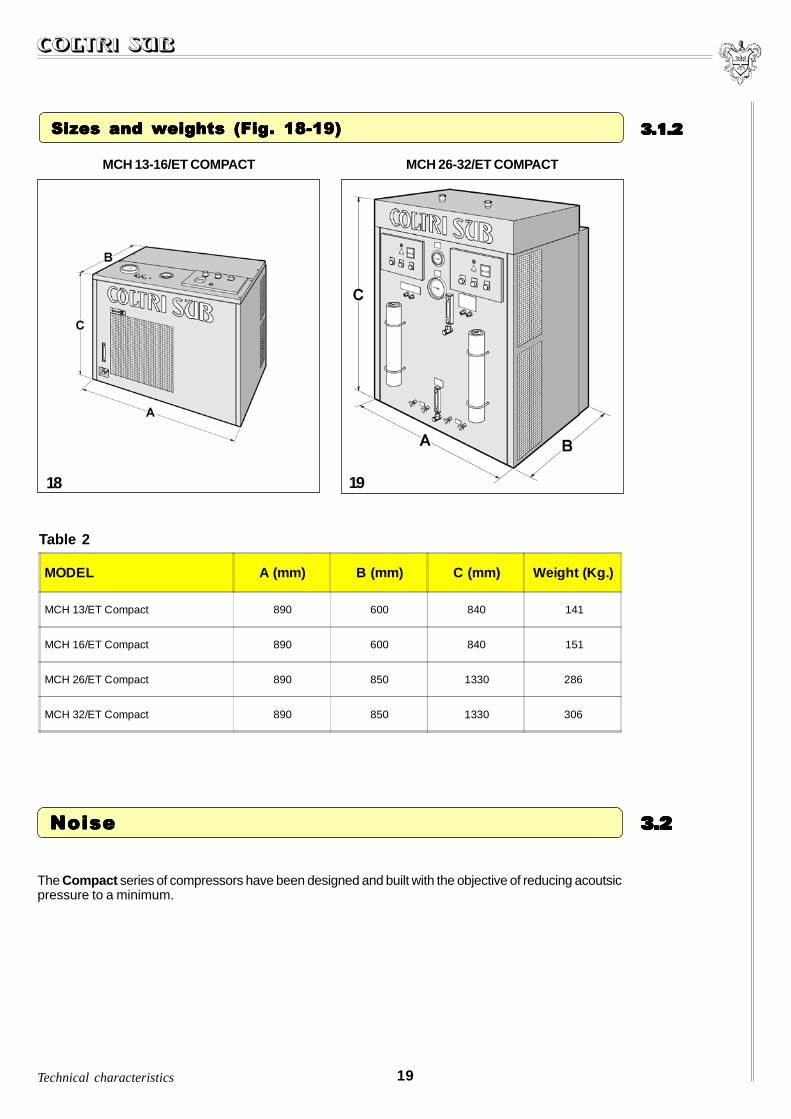
3.1.23.1.23.1.23.1.23.1.2 Sizes and weights (Fig. 18-19) Sizes and weights (Fig. 18-19) Sizes and weights (Fig. 18-19) Sizes and weights (Fig. 18-19) Sizes and weights (Fig. 18-19)
MODEL A (mm) B (mm) C (mm) Weight (Kg.)
MCH 13/ET Compact 890 600 840 141
MCH 16/ET Compact 890 600 840 151
MCH 26/ET Compact 890 850 1330 286
MCH 32/ET Compact 890 850 1330 306
MCH 13-16/ET COMPACT MCH 26-32/ET COMPACT
18 19
Table 2
19
3.23.23.23.23.2 Noise Noise Noise Noise Noise
The Compact series of compressors have been designed and built with the objective of reducing acoutsicpressure to a minimum.
Technical characteristics

20 Technical characteristics
Whenever the machines are used for work in environments where the daily noise level to which theoperators are exposed is higher than 80 dBA, the employer must take steps to apply all the measurementsnecessary to safeguard the operator’s health. In particular, the operators must, if necessary, use all theindividual protection devices to protect themselves from the noise level.
The reading of the machine noise level was takenfrom the “operator’s work place” (Fig. 20), with thefollowing methods and results:
20
METHODS OF MEASUREMENTISO 3746
MC
H 1
3/E
T C
ompa
ct
MC
H 1
6/E
T C
ompa
ct
MC
H 2
6/E
T C
ompa
ct
MC
H 3
2/E
T C
ompa
ct
Level of acoustic pressure at the operator’s work placeLevel of acoustic powerPeak level
dB(A) 79,4
dB(A) 91,5
-
dB(A) 81
dB(A) 94,5
-
dB(A) 72,4
dB(A) 92,7
-
dB(A) 75
dB(A) 97,1
-
INSTRUMENTS
Bruel & Kjacr sound level integrating meterMicrophone for sound level meterGauge
Mod. 2231 cl. 1
Mod. 4155 cl. 1
Mod. 4230 cl. 2
Table 3

PRECAPRECAPRECAPRECAPRECAUTIONS FOR USE UTIONS FOR USE UTIONS FOR USE UTIONS FOR USE UTIONS FOR USE ANDANDANDANDANDMAINTENANCEMAINTENANCEMAINTENANCEMAINTENANCEMAINTENANCE 44444
Refer to the specific “Safety Regulation Manual” which is supplied enclosed with this manual (and whichforms an integral part of the same).
4.1 Machine area diagrams ..................................................................................................... 21
4.1.1 Safety devices ............................................................................................................ 22
4.1.2 Residual risk areas .................................................................................................... 24
21Precautions for use and maintenance
4.14.14.14.14.1 Machine area diagrams Machine area diagrams Machine area diagrams Machine area diagrams Machine area diagrams
The MCH 13-16-26-32/ET Compact series of compressors are electrically driven, automatically operatedmachines.
Therefore the term “operator” as repeatedly defined in this manual refers to the following professionalfigures:
- PERSON IN CHARGE OF MAINTENANCE , this is the person entrusted with the handling, installation,start-up, regulation, cleaning, repair, changing of the tooling and maintenance of the machine.This person must be a qualified member of staff who has followed courses of specialization and whohas had experience with the handling, installation, start-up and maintenance of machines and plantsof a mechanical, electrical and pneumatic type.It is always advisable for the person in charge of maintenance to follow a training and specializationcourse on the machine given by the AEROTECNICA COLTRI S.r.l. technicians.
- PERSON IN CHARGE OF OPERATION, this is the person responsible for operating the machine whosework must be limited only to filling the cylinders and the control operations.This person must be perfectly acquainted with all the machine instructions and operating methods asdescribed in this manual and the regulation manual.
It is absolutely prohibited for the person in chargeof operation to carry out any tasks other thanthose described above or to work in areas otherthan those marked in figure 21.
21
22 Precautions for use and maintenance
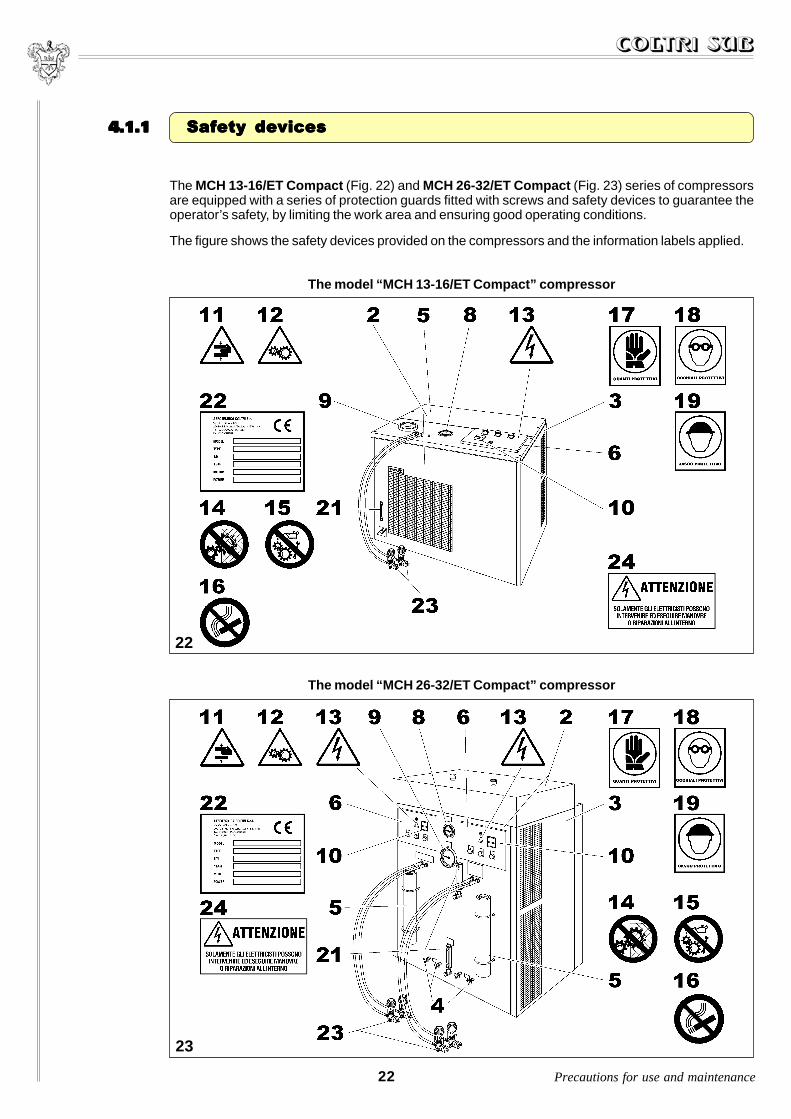
The MCH 13-16/ET Compact (Fig. 22) and MCH 26-32/ET Compact (Fig. 23) series of compressorsare equipped with a series of protection guards fitted with screws and safety devices to guarantee theoperator’s safety, by limiting the work area and ensuring good operating conditions.
The figure shows the safety devices provided on the compressors and the information labels applied.
4.1.14.1.14.1.14.1.14.1.1 Safety devices Safety devices Safety devices Safety devices Safety devices
The model “MCH 13-16/ET Compact” compressor
The model “MCH 26-32/ET Compact” compressor
22
23
23Precautions for use and maintenance
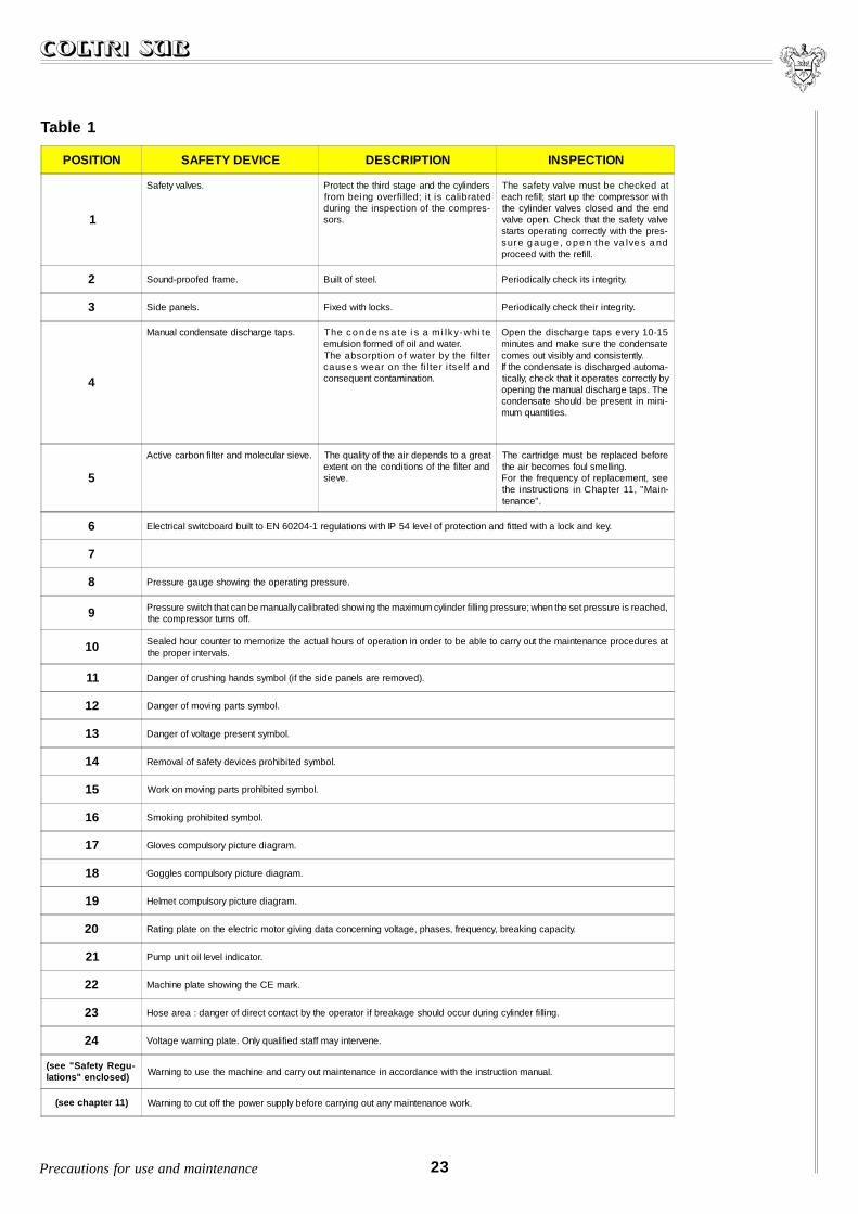
Table 1
POSITION SAFETY DEVICE DESCRIPTION INSPECTION
1
Safety valves. Protect the third stage and the cylindersfrom being overfi lled; i t is calibratedduring the inspection of the compres-sors.
The safety valve must be checked ateach refill; start up the compressor withthe cylinder valves closed and the endvalve open. Check that the safety valvestarts operating correctly with the pres-sure g aug e , o pe n the va lve s a ndproceed with the refill.
2 Sound-proofed frame. Built of steel. Periodically check its integrity.
3 Side panels. Fixed with locks. Periodically check their integrity.
4
Manual condensate discharge taps. The c onde ns a te i s a mi lky-whi teemulsion formed of oil and water.The absorption of water by the fi ltercauses wear on the fi lter i tself andconsequent contamination.
Open the discharge taps every 10-15minutes and make sure the condensatecomes out visibly and consistently.If the condensate is discharged automa-tically, check that it operates correctly byopening the manual discharge taps. Thecondensate should be present in mini-mum quantities.
5
Active carbon filter and molecular sieve. The quality of the air depends to a greatextent on the conditions of the filter andsieve.
The cartridge must be replaced beforethe air becomes foul smelling.For the frequency of replacement, seethe instructions in Chapter 11, "Main-tenance".
6 Electrical switcboard built to EN 60204-1 regulations with IP 54 level of protection and fitted with a lock and key.
7
8 Pressure gauge showing the operating pressure.
9 Pressure switch that can be manually calibrated showing the maximum cylinder filling pressure; when the set pressure is reached,the compressor turns off.
10 Sealed hour counter to memorize the actual hours of operation in order to be able to carry out the maintenance procedures atthe proper intervals.
11 Danger of crushing hands symbol (if the side panels are removed).
12 Danger of moving parts symbol.
13 Danger of voltage present symbol.
14 Removal of safety devices prohibited symbol.
15 Work on moving parts prohibited symbol.
16 Smoking prohibited symbol.
17 Gloves compulsory picture diagram.
18 Goggles compulsory picture diagram.
19 Helmet compulsory picture diagram.
20 Rating plate on the electric motor giving data concerning voltage, phases, frequency, breaking capacity.
21 Pump unit oil level indicator.
22 Machine plate showing the CE mark.
23 Hose area : danger of direct contact by the operator if breakage should occur during cylinder filling.
24 Voltage warning plate. Only qualified staff may intervene.
(see "Safety Regu-lations" enclosed) Warning to use the machine and carry out maintenance in accordance with the instruction manual.
(see chapter 11) Warning to cut off the power supply before carrying out any maintenance work.

24 Precautions for use and maintenance
In some areas of the machine there are some residual risks that could not be eliminated during thedesign phase or protected by guards due to the particular operation of the compressors modelMCH 13-16-26-32/ET Compact (Fig. 24-25). Each operator must be aware of the residual risks presenton the machine in order to avoid possible accidents.
4.1.24.1.24.1.24.1.24.1.2 Residual risk areas Residual risk areas Residual risk areas Residual risk areas Residual risk areas
24 25
Table 2
MCH 13-16-26-32/ET Compact
POSITION DESCRIPTION
1 Danger of polluting the air produced owing to the possibility of mixing fumes or vapours from the lubricating oil withthe compressed air produced.
2 Electrical danger. Use the machine with suitable protection from the electrical power supply especially in the presenceof water and humidity.
3 Danger deriving from the noise emitted by the compressor if maintenance work is carried out without the safetyguards.
4 Pump unit area : danger from heat. For any maintenance operation (requiring the removal of the safety guard) waitabout 30 minutes after turning off the engine.
5 Transmission belt area: danger of crushing or dragging by the belts when maintenance work is carried out withoutthe safety guards.
6 Cooling fan area: danger of impact and abrasion if the cylinders are refilled without the safety guards.

UNPUNPUNPUNPUNPAAAAACKING CKING CKING CKING CKING AND HANDLING AND HANDLING AND HANDLING AND HANDLING AND HANDLING THE MATHE MATHE MATHE MATHE MACHINECHINECHINECHINECHINE 55555This chapter provides the instructions necessary for unpacking and handling the machine.
5.1 Unpacking the machine ..................................................................................................... 25
5.2 Pack contents ..................................................................................................................... 26
5.3 Handling the machine ........................................................................................................ 26
25Unpacking and handling the machine
5.15.15.15.15.1 Unpacking the machine Unpacking the machine Unpacking the machine Unpacking the machine Unpacking the machine
The machines in the Compact series are delivered fully assembled, but with the hoses suppliedseparately.
The compressors are packed in cardboard boxes fitted on europallets to make handling and transportationeasier.
To unpack the boxes containing the machine,follow the instructions given on the outside of theboxes with great care (Fig. 26).
26

5.25.25.25.25.2 Pack contents Pack contents Pack contents Pack contents Pack contents
The standard equipment with which the machine is supplied is:
- 2 refill hoses measuring 1200 mm with valve for model MCH 13-16/ET Compact and 4 hoses for modelMCH 26-32/ET Compact;
- operating and maintenance booklet;
- enclosure with the Instruction Manual (Safety regulations);
- lubricating oil in cans (2 lt for model MCH 13-16/ET Compact and 4 lt for model MCH 26-32/ETCompact).
26 Unpacking and handling the machine
Having removed the compressor from its pack as described in the previous paragraph, the machine canbe moved to its place of installation.
To carry out this operation, it is necessary to usea fork-lift truck or transpallet (of a suitablecapacity), the forks of which must be positionedbetween the feet of the europallet on which themachine is placed (Fig. 27).
Model MCH 26-32/ET is fitted with special sidemembers fixed under the structure (Fig. 28) thatenable the machine to be lifted with a fork-lift truckeven when it is not on a europallet.
5.35.35.35.35.3 Handling the machine Handling the machine Handling the machine Handling the machine Handling the machine
27
28
IIIII NSTNSTNSTNSTNSTALLAALLAALLAALLAALLATIONTIONTIONTIONTION 66666This chapter provides a description of the operations for installing the machine.
The following instructions presume that the operator has already become familiar with the regulationsgiven in Chapter 4, “Precautions for use and maintenance”.
6.1 Positioning ......................................................................................................................... 27
6.2 Connections ....................................................................................................................... 28
6.2.1 Connecting the air intake extension......................................................................... 28
6.2.2 Connecting the refill hoses ....................................................................................... 32
6.2.3 Electrical connections .............................................................................................. 33
WARNING
Before proceeding with the installation operations described below, read Chapter 4, “Precautions for useand maintenance” carefully and proceed as directed.
27Installation
6.16.16.16.16.1 Positioning Positioning Positioning Positioning Positioning
1 Position the machine in the chosen area and check that it is on a level (the plane should not be at anangle of more than 5° to assure perfect lubrication). For the machine sizes, see paragraph 3.1.2“Sizes and weights”.
WARNINGThe compressors used on board boats can be certified with inspections by R.I.Na (Italian Register ofShipping), to be requested as a special supply.
2 Check that in the place chosen for installation there are suitable ventilation conditions:- a good change of air (several windows), no dust and no risks of explosion, corrosion or fire.
3 Use in environments with a temperature of over 40 °C makes it necessary to use synthetic lubricatingoil and air-conditioning must be provided for the environment.
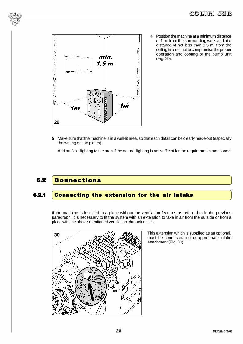
4 Position the machine at a minimum distanceof 1 m. from the surrounding walls and at adistance of not less than 1.5 m. from theceiling in order not to compromise the properoperation and cooling of the pump unit(Fig. 29).
5 Make sure that the machine is in a well-lit area, so that each detail can be clearly made out (especiallythe writing on the plates).
Add artificial lighting to the area if the natural lighting is not suffieint for the requirements mentioned.
29
6.26.26.26.26.2 ConnectionsConnectionsConnectionsConnectionsConnections
28 Installation
6.2.16.2.16.2.16.2.16.2.1 Connecting the eConnecting the eConnecting the eConnecting the eConnecting the extension fxtension fxtension fxtension fxtension for the air intakor the air intakor the air intakor the air intakor the air intakeeeee
If the machine is installed in a place without the ventilation features as referred to in the previousparagraph, it is necessary to fit the system with an extension to take in air from the outside or from aplace with the above-mentioned ventilation characteristics.
This extension which is supplied as an optional,must be connected to the appropriate intakeattachment (Fig. 30).
30

29Installation
To connect the extension, proceed as follows:
MCH 13-16/ET Compact1 Remove the upper protective cover by
unscrewing the fixing screws (Fig. 31).
MCH 26-32/ET Compact1 Remove the left-hand side protective cover
(looking at the compressor from the front ),by unscrewing the fixing screws (Fig. 32).
WARNING
Only use a flexible pipe provided with a steel spiral internal reinforcement to prevent bending and aconsequent reduction in the cross section.
MCH 26-32/ET Compact
MCH 13-16/ET Compact
32
31
30 Installation
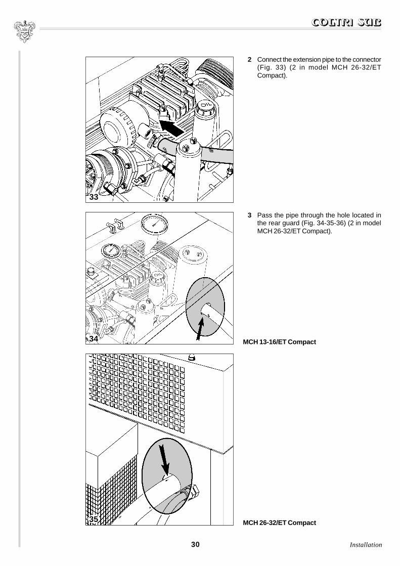
2 Connect the extension pipe to the connector(Fig. 33) (2 in model MCH 26-32/ETCompact).
3 Pass the pipe through the hole located inthe rear guard (Fig. 34-35-36) (2 in modelMCH 26-32/ET Compact).
33
MCH 26-32/ET Compact
34
35
MCH 13-16/ET Compact

31Installation
4 Fit the additional intake filter on the end ofthe extension pipe (Fig. 37) (2 in modelMCH 26-32/ET Compact).
5 Position the end of the extension on which the intake filter is fitted (air intake) in a ventilated placeprotected from atmospheric agents.
6 Direct the air intake in a position “againstthe wind” (Fig. 38).
37
MCH 26-32/ET Compact36
38

39
7 Make sure that there are no bends orbreakages along the length of the pipe(Fig. 39).
If the extension should have broken duringthe connection to the head, it must bereplaced.
WARNING
Make sure that the air intake is away fromexhaust fumes given off by internal-combustionengines or harmful fumes.
For the compressor model MCH 26-32/ET Compact, the following operations must be carriedout twice (bearing in mind that this model is double.
32 Installation
6.2.26.2.26.2.26.2.26.2.2 Connecting the refill hosesConnecting the refill hosesConnecting the refill hosesConnecting the refill hosesConnecting the refill hoses
1 Screw hose N° 1 into the special attachment“A” (Fig. 40) without securing it too tightly(see point 4).
2 Connect hose N°2 in the same way as described in the previous point (4 for the model MCH 26-32/ETCompact).
3 A torque wrench should be available to fasten the hoses.
40
41
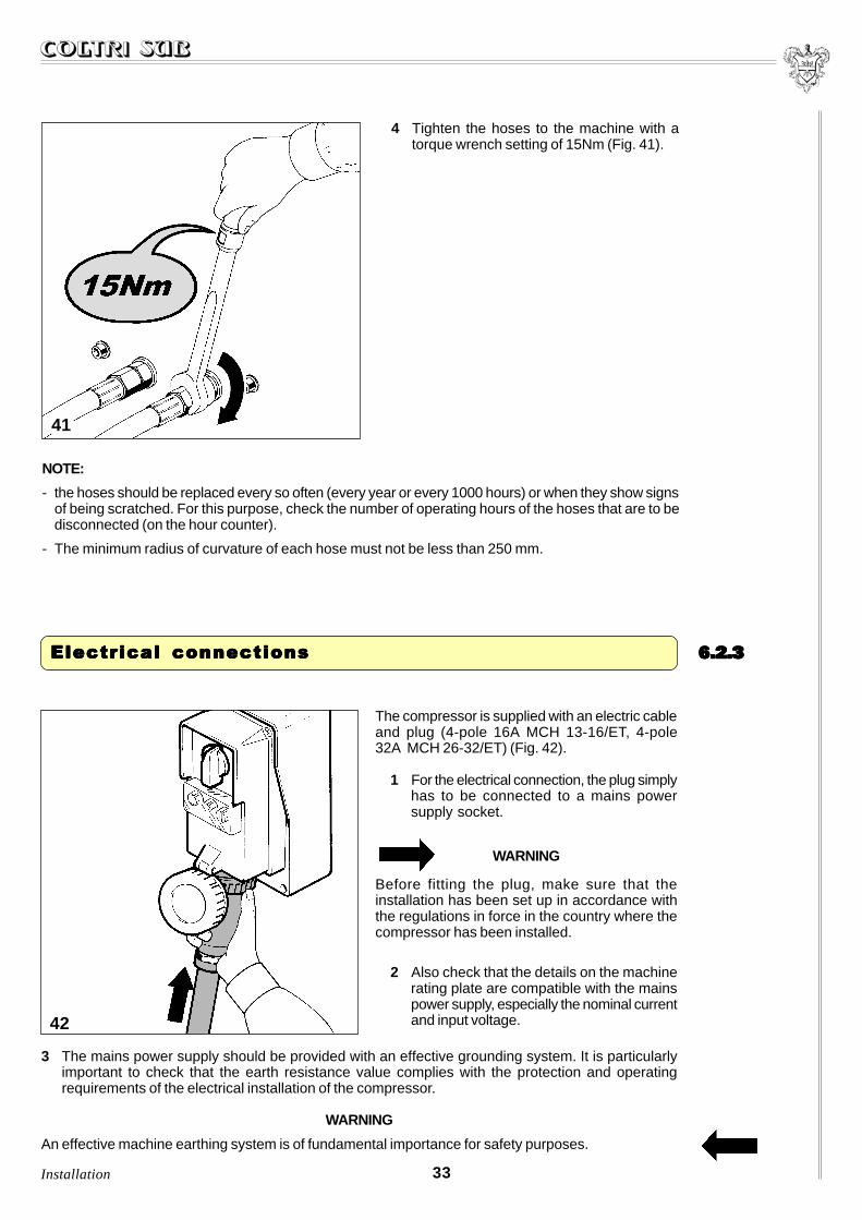
4 Tighten the hoses to the machine with atorque wrench setting of 15Nm (Fig. 41).
NOTE:
- the hoses should be replaced every so often (every year or every 1000 hours) or when they show signsof being scratched. For this purpose, check the number of operating hours of the hoses that are to bedisconnected (on the hour counter).
- The minimum radius of curvature of each hose must not be less than 250 mm.
33Installation
6.2.36.2.36.2.36.2.36.2.3Electrical connectionsElectrical connectionsElectrical connectionsElectrical connectionsElectrical connections
42
The compressor is supplied with an electric cableand plug (4-pole 16A MCH 13-16/ET, 4-pole32A MCH 26-32/ET) (Fig. 42).
1 For the electrical connection, the plug simplyhas to be connected to a mains powersupply socket.
WARNING
Before fitting the plug, make sure that theinstallation has been set up in accordance withthe regulations in force in the country where thecompressor has been installed.
2 Also check that the details on the machinerating plate are compatible with the mainspower supply, especially the nominal currentand input voltage.
3 The mains power supply should be provided with an effective grounding system. It is particularlyimportant to check that the earth resistance value complies with the protection and operatingrequirements of the electrical installation of the compressor.
WARNING
An effective machine earthing system is of fundamental importance for safety purposes.

CONTRCONTRCONTRCONTRCONTROL POL POL POL POL PANELANELANELANELANEL77777This chapter provides a description of the functions carried out by the various devices fitted on thecontrol panel.
7.1 Control panel ............................................................................................................... ....... 34
7.2 Indication and control devices .......................................................................................... 35
34 Control panel
7.17.17.17.17.1 Control panel Control panel Control panel Control panel Control panel
The control panel has three operating buttons and the hour counter to memorize the number of machineoperating hours (Fig. 43-44).
1 ON - green button.
It enables the compressor to be started up.
The button has a light inside that comes onwhen it is pressed.
(The general switch must be in the “ON”position).
2 OFF - red button.
It enables the compressor to be stopped.
The button has a light inside that comes onwhen the power supply is connected.
3 MANUAL PURGE - yellow button.
It enables the condensate to be purgedmanually.
This function permits the pressure presentinside the condensate separators and thefilter to be discharged, evacuating the con-densate through the electromagnetically-controlled valves.
This operation is normally carried out by thetimer at regular intervals.
4 HOUR COUNTER
It enables the actual operating hours to bememorized in order to be able to carry outthe maintenance work as provided for.
43
44
35Control panel
7.27.27.27.27.2Indication and control devicesIndication and control devicesIndication and control devicesIndication and control devicesIndication and control devices
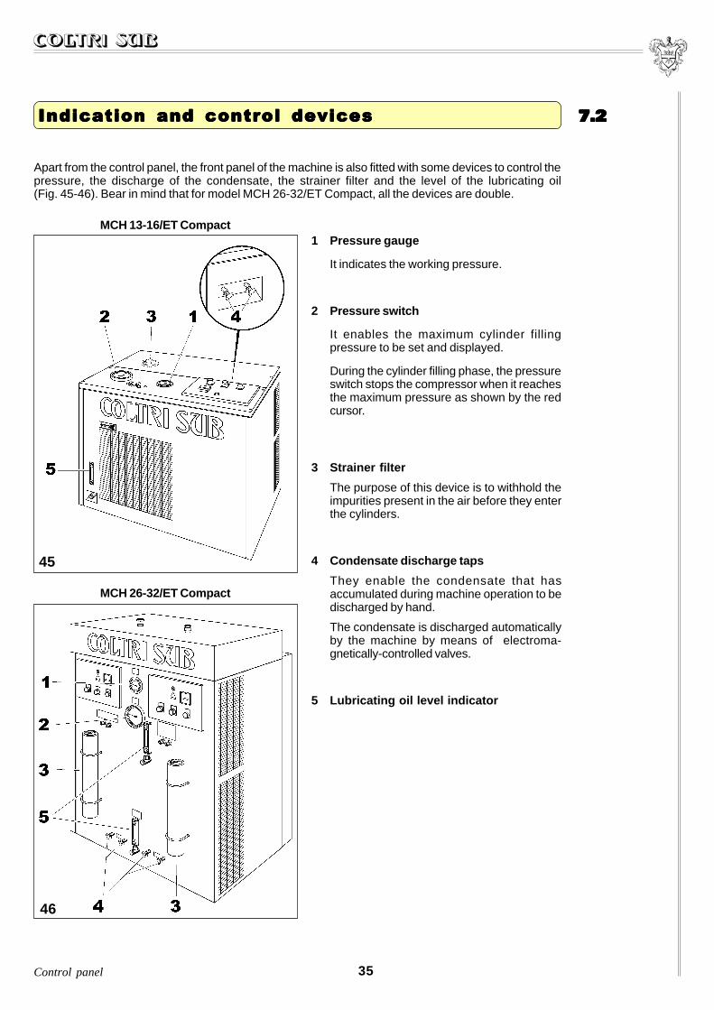
Apart from the control panel, the front panel of the machine is also fitted with some devices to control thepressure, the discharge of the condensate, the strainer filter and the level of the lubricating oil(Fig. 45-46). Bear in mind that for model MCH 26-32/ET Compact, all the devices are double.
1 Pressure gauge
It indicates the working pressure.
2 Pressure switch
It enables the maximum cylinder fillingpressure to be set and displayed.
During the cylinder filling phase, the pressureswitch stops the compressor when it reachesthe maximum pressure as shown by the redcursor.
3 Strainer filter
The purpose of this device is to withhold theimpurities present in the air before they enterthe cylinders.
4 Condensate discharge taps
They enable the condensate that hasaccumulated during machine operation to bedischarged by hand.
The condensate is discharged automaticallyby the machine by means of electroma-gnetically-controlled valves.
5 Lubricating oil level indicator
45
MCH 13-16/ET Compact
46
MCH 26-32/ET Compact

STSTSTSTSTARARARARART UPT UPT UPT UPT UP88888This chapter describes the operations regarding the machine start up phase.
The following instructions presume that the operator has already become familiar with the precautionsgiven in Chapter 4 “Precautions for use and maintenance” and that the machine has been installedaccording to the instructions given in the previous chapter.
8.1 Filling the machine ............................................................................................................ 36
8.2 Checks ................................................................................................................................ 37
36 Start up
8.18.18.18.18.1 Filling the machine Filling the machine Filling the machine Filling the machine Filling the machine
WARNING
Before proceeding with the start up operations described below, read chapter 4, “Precautions for useand maintenance” very carefully and follow the advice given.
Fill the lubricating oil sump of the pump unit whenthe machine is switched off.
The machine is delivered without lubricating oilwhich is collected in the cans that can be foundinside the machine packaging (Fig. 47).
47

The oil is added by removing the cap marked withthe word “OIL” (Fig. 48) for model MCH 13-16/ET,while for model MCH 26-32/ET the two oil capslocated on the upper cover of the machine(Fig. 49) and marked with the letters “A” and “B”must be unscrewed.
The quantity of oil to be poured in is 1.5 lt. and thelevel should be checked with the machine turnedoff, bearing in mind that an excess amount of oilmay cause infiltrations in the cylinders and adeposit on the valves. On the contrary, if the oillevel is too low, the tang of the connecting rod isprevented from providing the correct lubrication withthe possibility of causing a seizure of the cylinders.
To check the quantity of oil poured in, see thefollowing paragraph.
48
MCH 13-16/ET Compact
49
MCH 26-32/ET Compact
37Start up
8.28.28.28.28.2ChecksChecksChecksChecksChecks
1 Turn on the manual condensate dischargetaps (Fig. 50).
50

38 Start up
4 Check the level of the lubricating oil of the pumpunit by looking at the indicator located on thecontrol board (Fig. 52).
For model MCH 26-32/ET, as previously stated,there are two indicators provided, one for eachpump unit.
The indicators are marked by the letters “A”and “B” (Fig. 53) and correspond to the samemarks also shown on the relative oil caps.
When oil has to be added, this indication willbe used to establish, according to theindicator, which cap has to be unscrewed forthe filling operation.
If the level is too low, top the oil up followingthe instructions given in the previous paragraph.
If the level is too high, discharge some of theoil as described in chapter 11.4 “Changing thelubricating oil”.
To dispose of the oil, refer to chapter 10.2, “Disposal of waste”.
52
51
2 Turn the machine on by moving the generalswitch to the “ON” position. Check that themachine has been switched on by looking tosee the red light of the “OFF” button (Fig. 51).
3 Run the compressor for about 10 minutes thenleave it at a standstill for 20 minutes.
53
39Start up
54
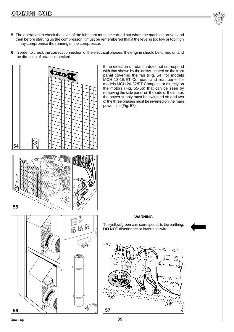
5 The operation to check the level of the lubricant must be carried out when the machine arrives andthen before starting up the compressor. It must be remembered that if the level is too low or too highit may compromise the running of the compressor.
6 In order to check the correct connection of the electrical phases, the engine should be turned on andthe direction of rotation checked.
If the direction of rotation does not correspondwith that shown by the arrow located on the frontpanel covering the fan (Fig. 54) for modelsMCH 13-16/ET Compact and rear panel formodels MCH 26-32/ET Compact, or directly onthe motors (Fig. 55-56) that can be seen byremoving the side panel on the side of the motor,the power supply must be switched off and twoof the three phases must be inverted on the mainpower line (Fig. 57).
55
56
WARNING
The yellow/green wire corresponds to the earthing.DO NOT disconnect or invert this wire.
57

U SU SU SU SU S EEEEE99999This chapter describes the operations required for refilling the cylinders.
The following instructions presume that the operator has already become familiar with the precautionsgiven in Chapter 4 “Precautions for use and maintenance” and that the machine has been started upaccording to the instructions given in the previous chapter.
9.1 Preliminary operations ....................................................................................................... 40
9.2 Refilling the cylinders ..................................................................................................... ... 43
WARNING
Before proceeding to use the machine as described below, read chapter 4, “Precautions for use andmaintenance” very carefully and follow the advice given.
40
9.19.19.19.19.1 Pr Pr Pr Pr Preliminareliminareliminareliminareliminar y opery opery opery opery operaaaaationstionstionstionstions
1 Check that the safety valve is operating properly by starting up the compressor with the end tapsturned off so that the pressure in the circuit rises quickly and the valve comes into operation at theset pressure.
The valve is pre-calibrated in the factory at a pressure of 225 bar or 330 bar.
WARNINGUnder no circumstances may the calibration pressure of these valves be increased. Any tamperingwith the safety valves may cause serious damage to the machine or to persons and a cancellation ofthe guarantee.
2 Check the condition of the cylinders to be filled.
DANGER
If the cylinders should show evident signs of internal and/or external corrosion, it is not advisable toproceed with the filling operation, even if they comply with inspection requirements.
WARNING
Only use inspected cylinders provided with the relative approval.
The cylinder operating and filling pressure values are given on the cylinders themselves.
It is prohibited to exceed this refill pressure value.
Use
41
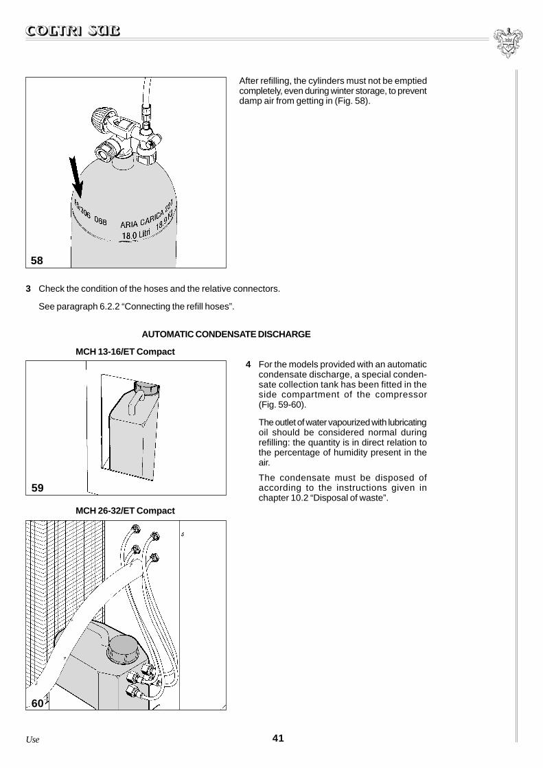
After refilling, the cylinders must not be emptiedcompletely, even during winter storage, to preventdamp air from getting in (Fig. 58).
3 Check the condition of the hoses and the relative connectors.
See paragraph 6.2.2 “Connecting the refill hoses”.
AUTOMATIC CONDENSATE DISCHARGE
4 For the models provided with an automaticcondensate discharge, a special conden-sate collection tank has been fitted in theside compartment of the compressor(Fig. 59-60).
The outlet of water vapourized with lubricatingoil should be considered normal duringrefilling: the quantity is in direct relation tothe percentage of humidity present in theair.
The condensate must be disposed ofaccording to the instructions given inchapter 10.2 “Disposal of waste”.
58
59
MCH 13-16/ET Compact
MCH 26-32/ET Compact
60
Use
42 Use
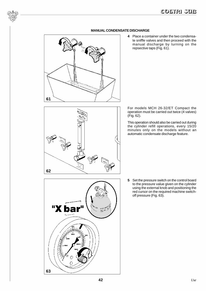
5 Set the pressure switch on the control boardto the pressure value given on the cylinderusing the external knob and positioning thered cursor on the required machine switch-off pressure (Fig. 63).
63
62
For models MCH 26-32/ET Compact theoperation must be carried out twice (4 valves)(Fig. 62).
This operation should also be carried out duringthe cylinder refill operations, every 15/20minutes only on the models without anautomatic condensate discharge feature.
MANUAL CONDENSATE DISCHARGE
61
4 Place a container under the two condensa-te sniffle valves and then proceed with themanual discharge by turning on therepsective taps (Fig. 61).

43Use
During this operation, the operator’s position is that shown in chapter 3.2 “Noise”.
WARNINGDuring the refilling of the cylinders it is compulsory for staff who are not involved with the task to keep adistance of at least three metres. Furthermore, it is not permitted to disconnect the hoses from theconnectors or from the refill tap while the machine is under pressure.
INDICATIONDuring the cylinder refill phase, it is advisable to immerse the cylinders in cold water in order to reducethe drop in pressure when the cylinders cool down.
The attachments are disponible: INT - DIN 200and DIN 300 (Fig. 64).
Each refill hose can be connected to a cylinderso that more than one cylinder can be refilled atthe same time.
Model MCH 26-32/ET can fill up to four cylindersat the same time with the hoses supplied as astandard fitting (Fig. 65).
The following operations must be repeated for eachhose that is to be connected to the cylinder to berefilled. Furthermore, it should be borne in mindthat for model MCH 26-32/ET Compact, eachcontrol panel on the machine is provided withcontrols that carry out the same functions (seechapter 7).
Each panel controls a pump unit while the 4 hosesare connected together and can refill up to 4cylinders using the compressors, eitherseparately or together. The period between refillsobviously depends on the use made of thecylinders.
64
65
9.29.29.29.29.2Refilling the cylindersRefilling the cylindersRefilling the cylindersRefilling the cylindersRefilling the cylinders
44 Use
67
68
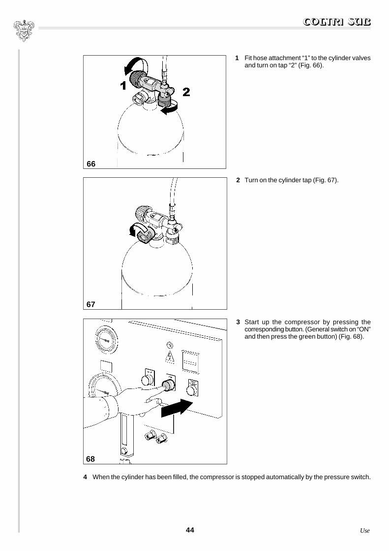
2 Turn on the cylinder tap (Fig. 67).
3 Start up the compressor by pressing thecorresponding button. (General switch on “ON”and then press the green button) (Fig. 68).
4 When the cylinder has been filled, the compressor is stopped automatically by the pressure switch.
66
1 Fit hose attachment “1” to the cylinder valvesand turn on tap “2” (Fig. 66).

45Use
6 Press the pressure bleed button on the refilltap and then disconnect the cylinderattachment (Fig. 70).
If an emergency situation should arise during therefilling of the cylinders, press the “OFF” buttonlocated on the control board (Fig. 71).
The machine is, in any case, provided with an emergency system that automatically blocks it when:
1) the pressure set on the pressure switch is reached;
2) there is a temporary cut in the power supply;
3) the heat release of the electric motor trips due to an overload.
After an emergency stop and before proceeding with a subsequent operation, it is necessary to checkthat the cause of the emergency has been eliminated.
70
71
69
5 Turn off the cylinder tap and that of the hoses(Fig. 69).

PUTTING PUTTING PUTTING PUTTING PUTTING THE MATHE MATHE MATHE MATHE MACHINE OUT OF OPERACHINE OUT OF OPERACHINE OUT OF OPERACHINE OUT OF OPERACHINE OUT OF OPERATIONTIONTIONTIONTIONANDANDANDANDAND DISMANTLING TH DISMANTLING TH DISMANTLING TH DISMANTLING TH DISMANTLING THE MACHINEE MACHINEE MACHINEE MACHINEE MACHINE1010101010
This chapter provides instructions to be followed for long machine standstills or for the dismantling ofthe same.
10.1 Instructions for prolonged machine standstills ................................................................ 46
10.2 Disposal of waste products ................................................................................................ 46
10.3 Dismantling the machine ................................................................................................... 47
WARNING
Before carrying out any procedure on the machine, read Chapter 4, “Precautions for use and maintenance”with care.
10.110.110.110.110.1 Instr Instr Instr Instr Instructions fuctions fuctions fuctions fuctions for pror pror pror pror prolongolongolongolongolonged maced maced maced maced machine standstillshine standstillshine standstillshine standstillshine standstills
If the compressor is not to be used for prolonged periods, remove the active carbon cartridge from thestrainer filter.
Run the compressor idle for a few minutes to drain off any residue condensate. Stop the compressor,remove the intake filter, start up the compressor again spraying a few drops of oil into the intake hole sothat a light film of lubricant is sucked in and penetrates the internal parts of the compressor.Stop the compressor and refit the intake air filter. Clean the external parts and try to remove any salinehumidity and oily deposits. Protect the compressor from dust and water by storing it in a clean, dryplace.
Turn the machine off using the general switch (position “0”) and remove the power plug.
Carry out a general cleaning operation on the machine and all its components.
46 Putting the machine out of operationand dismantling the machine
When using the compressor, special waste products are produced. It must be remembered that wastefrom industrial processes, agricultural, artisan and commercial activities and service industries cannotbe disposed of together with normal urban waste either because of their quality or quantity.Old or obsolete machinery is also to be considered as special waste.
Special care must be taken with the disposal of worn active carbon filters which, being a waste productthat cannot be disposed of together with normal urban waste, must be dealt with in compliance with thelaws in force in the country where the compressor is installed.
10.210.210.210.210.2 Disposal of waste products Disposal of waste products Disposal of waste products Disposal of waste products Disposal of waste products

It is important to remember that the loading and discharge of waste oil, special waste products and toxicor harmful waste products deriving from industrial or artisan processes must be registered.The collection of waste oils and special toxic or harmful waste products must be carried out by speciallyauthorized companies.
The disposal of waste oils in particular must be carried out in accordance with the regulations in force inthe user’s country.
47Putting the machine out of operationand dismantling the machine
10.310.310.310.310.3 Dismantling the machine Dismantling the machine Dismantling the machine Dismantling the machine Dismantling the machine
The operations required for stripping and demolishing the machine must be carried out byqualified staff.
To dismantle the machine, follow the regulations imposed by the laws in force in the user’s country.Before demolishing the machine, an inspection must be requested by the competent authority with theissuing of a relative report.
Disconnect the machine from the power supply.
Remove any interfacing that there may be between the compressor and other machines, checkingcarefully that any interfacing between other machines that are still in use remain operative.
Empty the tank containing the lubricating oil and store it according to legal requirements.
Proceed with the stripping of the individual machine components, grouping them together according totheir composition. The machine consists mainly of components made of steel, stainless steel, castiron, aluminium and plastic.
Finally, send the materials for scrap in accordance with the laws in force in the country where thecompressor is installed.
During all the dismantling phases, follow the safety warnings given in this manual with greatcare.
MAMAMAMAMAINTENANCEINTENANCEINTENANCEINTENANCEINTENANCE1111111111This chapter includes instructions concerning the preventive, routine and additional maintenanceoperations.
In the specifications for the preventive maintenance operations for the various devices indication is alsogiven of the frequency of such procedures.
Before consulting the chapter, read Chapter 4 “Precautions for use and maintenance” with care.
11.1 General notes ..................................................................................................................... 48
11.2 Preventive maintenance ..................................................................................................... 49
11.3 Changing the lubricant oil ................................................................................................. 50
11.4 Checking the transmission belt ......................................................................................... 52
11.5 Air intake filter ................................................................................................................... 53
11.6 Active carbon filter and molecular sieve .......................................................................... 55
11.7 Refill hose ........................................................................................................................... 57
11.8 Intake and discharge valves .............................................................................................. 58
11.9 Heads .................................................................................................................................. 58
11.10 Cylinders ............................................................................................................................ 59
11.11 Maintenance programme .................................................................................................. 60
WARNING
All the routine and additional maintenance operations must be carried out with the machine at a standstill(the compressor at a standstill) and with the power supply disconnected.
The residue pressure in the machine (pump circuit) must be eliminated.
Any operation carried out on the machine must only be undertaken having read and carefully applied theregulations listed in Chapter 4 “Precautions for use and maintenance”.
All the operations described in the following paragraphs, for model MCH 26-32/ET Compact,must be repeated twice (one for every component that is the same).
48 Maintenance
To keep the machine in good working condition, it must be cleaned very thoroughly.
Having been designed and built according to the most advanced technological criteria, this type of refillstation requires very limited preventive and routine maintenance operations.
However, it is essential to follow the indications given in this chapter very carefully and to follow theintervals between operations as suggested.
11.111.111.111.111.1 General notes

During the guarantee period no responsibility is taken for any damage or operating faults due to a failureto comply with the regulations in force.
The following paragraph enables all the routine and additional maintenance operations carried out on themachine to be recorded.
This paragraph should be filled in carefully and any operations carried out to solve problems should alsobe reported.
49Maintenance
11.211.211.211.211.2 Pr Pr Pr Pr Preeeeevvvvventientientientientivvvvve maintenance (Te maintenance (Te maintenance (Te maintenance (Te maintenance (Taaaaabbbbble 1)le 1)le 1)le 1)le 1)
Table 1INTERVALS
x 1 day 15 min 30 min 25 h 50 h 125 h 250 h 500 h 1000 h 5000 h
1 Replace the active carboncartridge, see par. 11.7
2 Check the compressor oil level O
3 First compressor oil change O
4 Change compressor oil O
5 Intake filter cartridge O O
6 Operation of the end safety valve O
7 Operation and tightness of therefill valve O
8Alignment of the compressor
needle with the O when thecompressor is depressurized
O
9 Tightening of the cooling pipes O
10 Tightening of the connecting pipes O
11 Belt tension and wear O O
12 Hose replacement O
13 2nd and 3rd stage intake anddischarge valves O
14 Internal cleaning of end separator O
15 Tightening of all the screws O
16 General cleaning O
17 Replacement of the externalcasing of the strainer filter O
18 Replacement of 1st stage head O
O= replacement O= inspection, cleaning

50
The quantity of oil for the lubrication of the pump unit must be checked every 25 hours.
To carry out this operation, see chapter 8 “Start up”.
The oil must be changed every 250 operating hours or yearly.
When changing the oil, it must be remembered that a mixture of different oils cannot be used.
The oil must have the following characteristics:
To change the oil, proceed as follows:
1 Use a basin with a minimum capacity of2.5 lt. capacity under the oil discharge tap(Fig. 72).
2 Unscrew the hexagonal closing cap located in front of the oil discharge.
11.311.311.311.311.3 Changing the lubricant oil (T Changing the lubricant oil (T Changing the lubricant oil (T Changing the lubricant oil (T Changing the lubricant oil (Taaaaabbbbble 2)le 2)le 2)le 2)le 2)
Sump capacity cu.cm.litres/gallons
15001.5/0.476
Recommended oils
AEROTECNICA COLTRI SPECIAL MINERAL OILAEROTECNICA COLTRI SPECIAL SYNTHETIC OIL
MOBIL SPECIAL 20 W 50MOBIL RARUS 827-829
ANDEROL 755 SYNTHETIC
Viscosity of the oilsummer
winter
above +10 °C (50 °F) SAE 20 W/40
from +10 °C to -15 °C (50° to 5 °F) SAE 10 Wbelow -15 °C (5 °F) SAE 5 W
Maximum tilt of thecompressor with the oillevel at maximum
degrees ~ 5
72
Table 2
Maintenance

51
3 Open the oil discharge two taps (Fig. 73)and discharge all the oil in the sumps.
4 Close the discharge tap and replace the hexagonal closing cap.
5 Carry out the filling operations as described in chapter 8 “Start up”.
WARNING
To dispose of waste oils follow the instructions given in chapter 10.2 “Disposal of waste products” withgreat care.
Maintenance
73

52
75
The drive belt control involves measuring the flex herself.
This operation must be carried out every 250machine operating hours as described below:
1 Remove the protective cover as shown onfigures 74 and 75, by unscrewing the fixingscrews.
Checking the transmission belt Checking the transmission belt Checking the transmission belt Checking the transmission belt Checking the transmission belt11.411.411.411.411.4
74
Maintenance
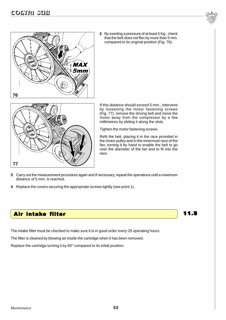
2 By exerting a pressure of at least 5 Kg., checkthat the belt does not flex by more than 5 mm.compared to its original position (Fig. 76).
If this distance should exceed 5 mm., interveneby loosening the motor fastening screws(Fig. 77), remove the driving belt and move themotor away from the compressor by a fewmillimetres by sliding it along the slots.
Tighten the motor fastening screws.
Refit the belt, placing it in the race provided inthe motor pulley and in the innermost race of thefan, turning it by hand to enable the belt to goover the diameter of the fan and to fit into therace.
76
77
3 Carry out the measurement procedure again and if necessary, repeat the operations until a maximumdistance of 5 mm. is reached.
4 Replace the covers securing the appropriate screws tightly (see point 1).
53
The intake filter must be checked to make sure it is in good order every 25 operating hours.
The filter is cleaned by blowing air inside the cartridge when it has been removed.
Replace the cartridge turning it by 60° compared to its initial position.
Maintenance
11.511.511.511.511.5 Air intakAir intakAir intakAir intakAir intake filtere filtere filtere filtere filter
54
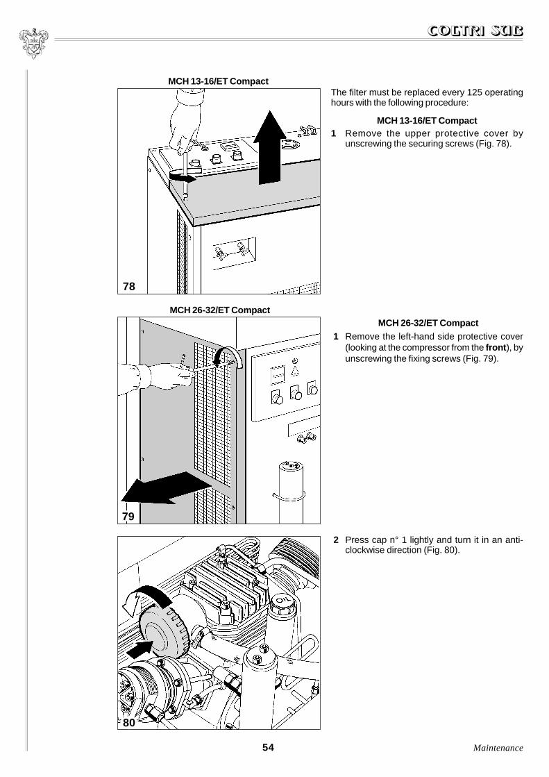
The filter must be replaced every 125 operatinghours with the following procedure:
MCH 13-16/ET Compact1 Remove the upper protective cover by
unscrewing the securing screws (Fig. 78).
MCH 26-32/ET Compact1 Remove the left-hand side protective cover
(looking at the compressor from the front ), byunscrewing the fixing screws (Fig. 79).
MCH 26-32/ET Compact
MCH 13-16/ET Compact
78
79
2 Press cap n° 1 lightly and turn it in an anti-clockwise direction (Fig. 80).
80
Maintenance

3 Remove the filter and replace it with a newone (Fig. 81).
To order a new spare filter, refer to chapter14 “Spare parts”.
4 Refit the safety guard and tighten the screws (see point 1).
81
55
The cartridges must be replaced before the air becomes foul-smelling.
The quality of the air depends to a large extent on the condition of the filtering cartridge. For this reason,it is important to comply with the intervals as specified.
The frequency of replacement has been calculated for use of the compressor with intake air at a tempe-rature of 20 °C (68 °F), see table 4. If the temperatures differ, apply the coefficients given in the followingtable 3 to the duration of the filter:
11.611.611.611.611.6 Active carbon filter and molecular sieve Active carbon filter and molecular sieve Active carbon filter and molecular sieve Active carbon filter and molecular sieve Active carbon filter and molecular sieve
°C °FMultiplicativecoefficients
50 122 0.20
40 104 0.34
30 86 0.57
20 68 1
10 50 1.85
5 41 2.60
0 32 3.80
Table 3
Maintenance
56
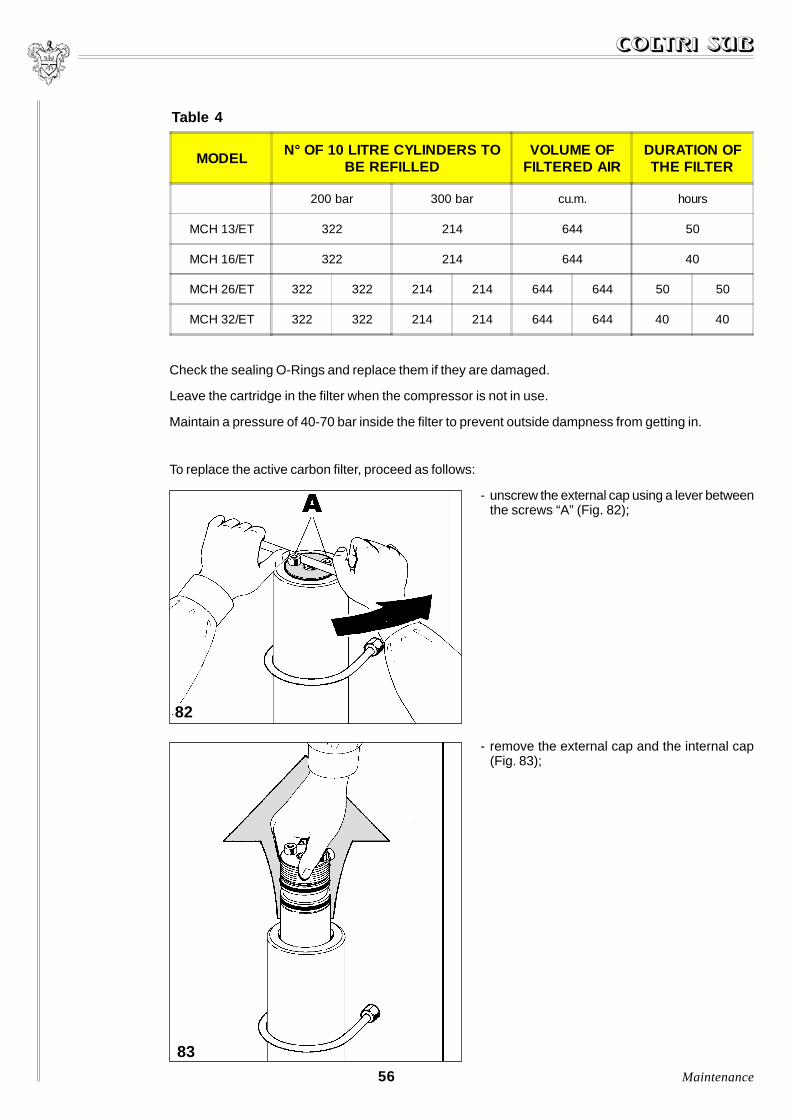
Check the sealing O-Rings and replace them if they are damaged.
Leave the cartridge in the filter when the compressor is not in use.
Maintain a pressure of 40-70 bar inside the filter to prevent outside dampness from getting in.
MODELN° OF 10 LITRE CYLINDERS TO
BE REFILLEDVOLUME OF
FILTERED AIRDURATION OFTHE FILTER
200 bar 300 bar cu.m. hours
MCH 13/ET 322 214 644 50
MCH 16/ET 322 214 644 40
MCH 26/ET 322 322 214 214 644 644 50 50
MCH 32/ET 322 322 214 214 644 644 40 40
Table 4
To replace the active carbon filter, proceed as follows:
- unscrew the external cap using a lever betweenthe screws “A” (Fig. 82);
- remove the external cap and the internal cap(Fig. 83);
83
82
Maintenance
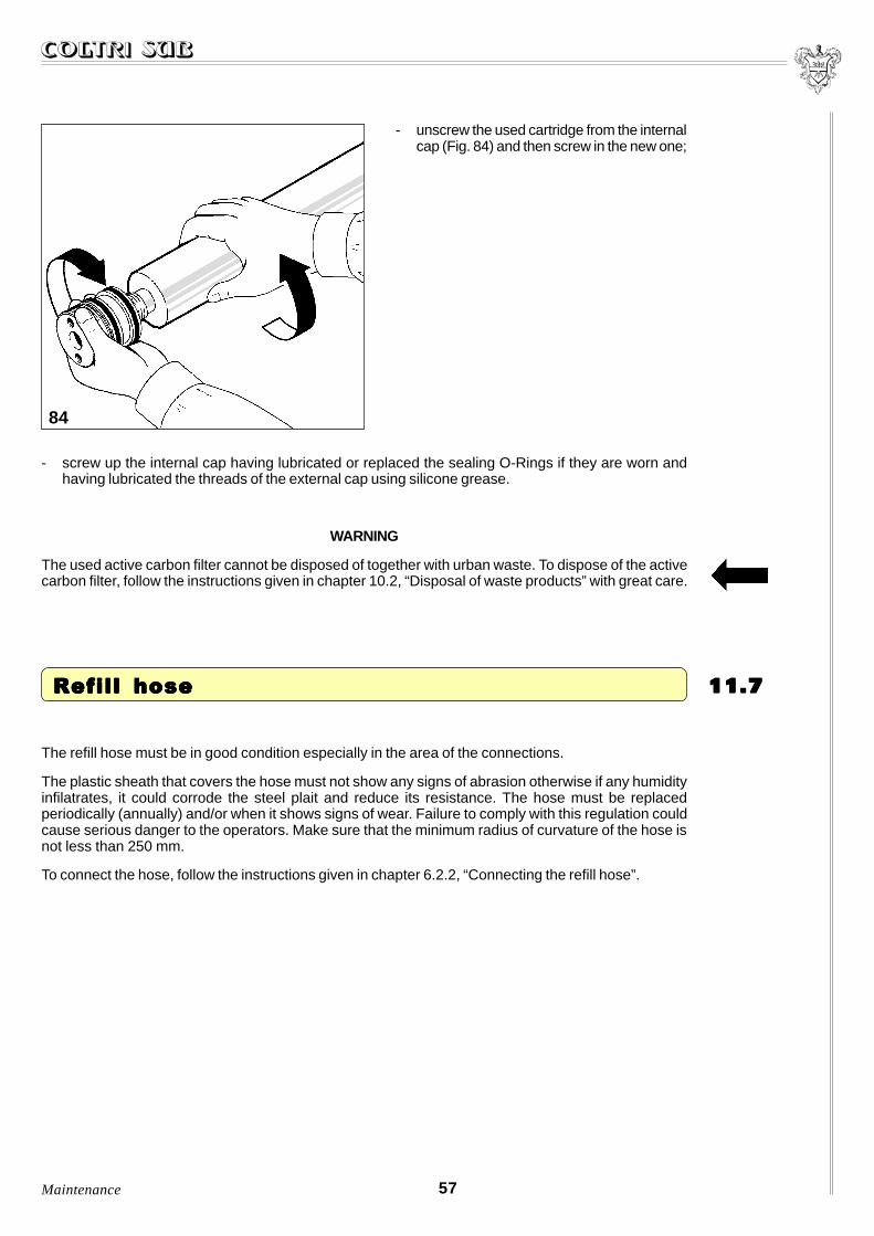
- unscrew the used cartridge from the internalcap (Fig. 84) and then screw in the new one;
84
- screw up the internal cap having lubricated or replaced the sealing O-Rings if they are worn andhaving lubricated the threads of the external cap using silicone grease.
WARNING
The used active carbon filter cannot be disposed of together with urban waste. To dispose of the activecarbon filter, follow the instructions given in chapter 10.2, “Disposal of waste products” with great care.
57
The refill hose must be in good condition especially in the area of the connections.
The plastic sheath that covers the hose must not show any signs of abrasion otherwise if any humidityinfilatrates, it could corrode the steel plait and reduce its resistance. The hose must be replacedperiodically (annually) and/or when it shows signs of wear. Failure to comply with this regulation couldcause serious danger to the operators. Make sure that the minimum radius of curvature of the hose isnot less than 250 mm.
To connect the hose, follow the instructions given in chapter 6.2.2, “Connecting the refill hose”.
11.711.711.711.711.7 Refill hose Refill hose Refill hose Refill hose Refill hose
Maintenance

The 2nd stage intake valve can be removed for maintenance purposes while those of the 1st, 2nd (onlydischarge) and 3rd stages must be entirely replaced. The seats must be cleaned carefully using petroland soft brass or nylon brushes.
The torque wrench setting for the head bolts of the 3rd stage is initially 1 Kgm. Having moved the headcloser, tighten the bolts to 2.2 Kgm, making sure that the piston is at the bottom dead centre during theoperation.
Avoid using steel brushes or screwdrivers. The interval between maintenance operations is 400-600working hours. If any parts are damaged or worn, they must be replaced. The discharge valves can beremoved from the outside while the intake valves can only be removed when the head of the cylinder hasbeen taken off.
NOTE: the valve replacement procedure must be carried out at the work bench by specialized technicianswho have specific equipment for the stripping operation.
In any case, it is preferable to contact AEROTECNICA COLTRI S.r.l. who will supply the necessarytechnical assistance.
11.811.811.811.811.8 Intak Intak Intak Intak Intake and disce and disce and disce and disce and discharharharharharggggge ve ve ve ve valvalvalvalvalveseseseses
58
11.911.911.911.911.9 Heads Heads Heads Heads Heads
85
- The head of the 1st stage (A) is of the lamellartype (Fig. 85). It must be fitted so that theword “TOP” remains upwards and the flapscorrespond with the openings in the coverof the head. Replace every 1000 hours.
Maintenance

87
86
- The head of the 2nd stage (B) is made ofaluminium (Fig. 86), the valves are screwedin; the intake valve inside is removed usinga special pin wrench while the dischargevalve is on the outside and is removed witha non-adjustable wrench or a box wrench.
- The head of the 3rd stage (C) is made ofaluminium (Fig. 87), the intake valve isscrewed inside and is removed using aspecial pin wrench while the discharge val-ve is on the oustide and is kept in positionby the threaded dowel which is screwed intothe cover.
59
11.1011.1011.1011.1011.10 Cylinders Cylinders Cylinders Cylinders Cylinders
After removing the cylinders, it is necessary tocheck, when they are replaced, that the pistonat the maximum point and the upper edge of thecylinder are on the same level (Fig. 88).
Adjust any differences that there may be bymaking the base of the cylinder thicker usinggaskets.
88
Maintenance
60
11.1111.1111.1111.1111.11 Maintenance programme Maintenance programme Maintenance programme Maintenance programme Maintenance programme
Use the following pages to note the routine and additional maintenance operations carried out on themachine.
If the maintenance programme is filled in accurately, it will be easier for the technician to intervene ifassistance is required.
Date: ..................................................................................................................................................
Operation carried out: .........................................................................................................................
Date: ..................................................................................................................................................
Operation carried out: .........................................................................................................................
Date: ..................................................................................................................................................
Operation carried out: .........................................................................................................................
Date: ..................................................................................................................................................
Operation carried out: .........................................................................................................................
Date: ..................................................................................................................................................
Operation carried out: .........................................................................................................................
Date: ..................................................................................................................................................
Operation carried out: .........................................................................................................................
Date: ..................................................................................................................................................
Operation carried out: .........................................................................................................................
Date: ..................................................................................................................................................
Operation carried out: .........................................................................................................................
Date: ..................................................................................................................................................
Operation carried out: .........................................................................................................................
Date: ..................................................................................................................................................
Operation carried out: .........................................................................................................................
Date: ..................................................................................................................................................
Operation carried out: .........................................................................................................................
Date: ..................................................................................................................................................
Operation carried out: .........................................................................................................................
Date: ..................................................................................................................................................
Operation carried out: .........................................................................................................................
Date: ..................................................................................................................................................
Operation carried out: .........................................................................................................................
Date: ..................................................................................................................................................
Operation carried out: .........................................................................................................................
Maintenance

61
Date: ..................................................................................................................................................
Operation carried out: .........................................................................................................................
Date: ..................................................................................................................................................
Operation carried out: .........................................................................................................................
Date: ..................................................................................................................................................
Operation carried out: .........................................................................................................................
Date: ..................................................................................................................................................
Operation carried out: .........................................................................................................................
Date: ..................................................................................................................................................
Operation carried out: .........................................................................................................................
Date: ..................................................................................................................................................
Operation carried out: .........................................................................................................................
Date: ..................................................................................................................................................
Operation carried out: .........................................................................................................................
Date: ..................................................................................................................................................
Operation carried out: .........................................................................................................................
Date: ..................................................................................................................................................
Operation carried out: .........................................................................................................................
Date: ..................................................................................................................................................
Operation carried out: .........................................................................................................................
Date: ..................................................................................................................................................
Operation carried out: .........................................................................................................................
Date: ..................................................................................................................................................
Operation carried out: .........................................................................................................................
Date: ..................................................................................................................................................
Operation carried out: .........................................................................................................................
Date: ..................................................................................................................................................
Operation carried out: .........................................................................................................................
Date: ..................................................................................................................................................
Operation carried out: .........................................................................................................................
Date: ..................................................................................................................................................
Operation carried out: .........................................................................................................................
Date: ..................................................................................................................................................
Operation carried out: .........................................................................................................................
Date: ..................................................................................................................................................
Operation carried out: .........................................................................................................................
Maintenance

TRTRTRTRTROUBLESHOOOUBLESHOOOUBLESHOOOUBLESHOOOUBLESHOOTINGTINGTINGTINGTING1212121212This chapter describes the faults that may arise during machine operation.
For each fault, the cause and the solution to be adopted are specified.
12.1 List of faults ....................................................................................................................... 62
62
Table 1 below lists all the faults that may arise during operation and the relative solution.
12.112.112.112.112.1 List of faults
PROBLEM CAUSE SOLUTION
The electric motor does not start A phase is missing Check the fuses
The safety valve of the 1st stage discharges The 2nd stage valves are not workingPerform maintenance operations or
replace the valves
The safety valve of the 2nd stage discharges The 3rd stage valves are not working Replace them
The speed of rotation andcapacity are reduced
The motor power is insufficient Check the motor and the power line
The belt slips Tighten the belt
The capacity is reduced without a reductionin the speed of rotation
The valves are not working Contact the technical assistance service
The 3rd stage piston is worn Contact the technical assistance service
The connections are loose or the gasketsleak
Check the leaks with water and soap andeliminate them
The intake filter is blocked Replace it
The intake extension is bent Straighten it, use a semi-rigid pipe
The piston or compression rings are worn Contact the technical assistance service
Smell of oil in the air
The filter cartridge is worn Replace it
The compression rings are worn Contact the technical assistance service
The compressor overheats
Wrong direction of rotationCheck the direction of rotation by inverting
the two phases in the plug
The cooling pipes are dirty Contact the technical assistance service
The valves are not completely closed(causing an overload of another stage)
Contact the technical assistance service
Table 1
Troubleshooting

13.1 Compression diagram ........................................................................................................ 63
13.2 Electrical diagram ............................................................................................................. . 64
MACHINE DIAGRAMSMACHINE DIAGRAMSMACHINE DIAGRAMSMACHINE DIAGRAMSMACHINE DIAGRAMS 1313131313
This chapter provides the plans and diagrams of the systems installed on the machine.
63
13.113.113.113.113.1 Compression diagram Compression diagram Compression diagram Compression diagram Compression diagram
Machine diagrams
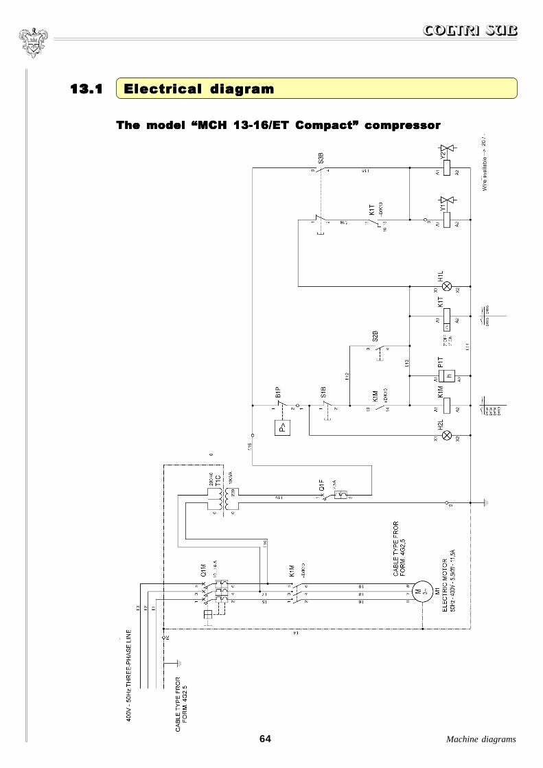
64 Machine diagrams
13.113.113.113.113.1 Electrical diagram Electrical diagram Electrical diagram Electrical diagram Electrical diagram
The model �MCH 13-16/ET Compact� compressorThe model �MCH 13-16/ET Compact� compressorThe model �MCH 13-16/ET Compact� compressorThe model �MCH 13-16/ET Compact� compressorThe model �MCH 13-16/ET Compact� compressor

65
The model �MCH 26-32/ET Compact� compressorThe model �MCH 26-32/ET Compact� compressorThe model �MCH 26-32/ET Compact� compressorThe model �MCH 26-32/ET Compact� compressorThe model �MCH 26-32/ET Compact� compressor
Machine diagrams
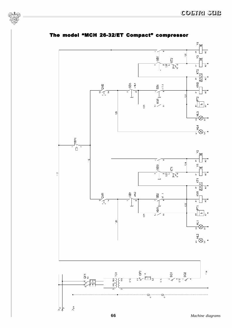
66 Machine diagrams
The model �MCH 26-32/ET Compact� compressorThe model �MCH 26-32/ET Compact� compressorThe model �MCH 26-32/ET Compact� compressorThe model �MCH 26-32/ET Compact� compressorThe model �MCH 26-32/ET Compact� compressor

67Machine diagrams
POS. TO BE READ
GENERALQS1 MAIN SWITCHQF1 PRIMARY AUSILIARIES PROTECTION SWITCHTC1 AUSILIARIES TRASFORMER (380/220 OR 220/220)QF2 SECONDARY AUSILIARIES PROTECTION SWITCHBP1 PRESSURE SWITCHSQ1 MECHANICAL PROTECTION CONTROLSQ2 MECHANICAL PROTECTION CONTROL
MOTOR M1QM1 OVERLOAD RELEASE MOTOR PROTECTION SWITCHKM1 MOTOR CONTROL CONTACTORM1 MOTORSB1 STOPPING PUSH BOTTONSB2 STOPPING PUSH BOTTONSB3 PURGE PUSH BOTTONHL2 READY STATE RUNNING SIGNALING (GREEN)HL1 RUNNING SIGNALING (RED)PT1 HOURS COUNTERKT1 CHARGE-PURGE TIMERY1 SOLENOID VALVE TO CHARGEY2 SOLENOID VALVE TO PURGE
MOTOR M2QM2 OVERLOAD RELEASE MOTOR PROTECTION SWITCHKM2 MOTOR CONTROL CONTACTORM2 MOTORSB5 STOPPING PUSH BOTTONSB6 STOPPING PUSH BOTTONSB7 PURGE PUSH BOTTONHL4 READY STATE RUNNING SIGNALING (GREEN)HL3 RUNNING SIGNALING (RED)PT2 HOURS COUNTERKT2 CHARGE-PURGE TIMERY3 SOLENOID VALVE TO CHARGEY4 SOLENOID VALVE TO PURGE

68

SPSPSPSPSPARE PARE PARE PARE PARE PARARARARARTSTSTSTSTS 141414141414.1 Exploded view of the machine parts .............................................................................. 69
Monobloc ....................................................................................................................... . 70
Pistons rod unit ............................................................................................................... 72
Cylinders unit .................................................................................................................. 74
Head unit ...................................................................................................................... ... 76
Cooling pipes .................................................................................................................. 78
Filtering system ............................................................................................................... 80
MCH 13-16/ET condensate trap ...................................................................................... 82
MCH 26-32/ET condensate trap ...................................................................................... 84
MCH 13-16/ET .................................................................................................................. 86
MCH 26-32/ET .................................................................................................................. 88
MCH 26-32/ET front panel ............................................................................................... 90
69Spare parts
14.114.114.114.114.1 Exploded vie Exploded vie Exploded vie Exploded vie Exploded view ofw ofw ofw ofw of the mac the mac the mac the mac the machine parhine parhine parhine parhine par tststststs

074
073
Mo
no
blo
cM
on
ob
loc
Mo
no
blo
cM
on
ob
loc
Mo
no
blo
c
70S
pa
re p
arts
076088090
060059058
065061
050091
067066
055042
052
064054
016
062
008070071
068040055
001

71Spare parts
MonoblocMonoblocMonoblocMonoblocMonobloc
POS. CODE DESCRIPTION001 13-00-0001 MONOBLOC008 13-01-0008 FIRST STAGE TIE ROD016 13-03-0016 THIRD STAGE TIE ROD040 13-02-0040 SECOND STAGE TIE ROD042 13-00-0042 FLANGE ROLLER BEARING NU305050 13-00-0050 FILTER SIDE FLANGE052 13-00-0052 OIL DISCHARGE EXTENSION054 13-00-0021 CORNER ¹/8 PIPE FITTING 8 mm. RILSAN055 13-00-0055 SEEGER RETAINING RING J 62058 13-00-0018 8 mm. NUT059 13-00-0009 8 mm. FLAT WASHER060 13-00-0018 8 mm. NUT061 13-00-0061 OIL FILLING PIPE O-RING062 13-00-0062 FLANGE O-RING064 13-00-0064 OIL LEVEL CONTROL PIPE065 13-00-0065 OIL FILLING PIPE FITTING066 13-00-0048 8x25 TCE SCREW067 13-00-0067 6x35 TCE SCREW068 13-00-0062 FLANGE O-RING070 13-00-0070 BALL BEARING 6302071 13-00-0071 FAN SIDE FLANGE073 13-00-0073 OIL SPLASH GUARD 30-48-8074 13-00-0074 FAN-HOLDING HUB076 13-00-0076 OIL FILLING PIPE WITH UPPER FLANGE088 13-00-0088 8 mm. THREADED ROD090 13-00-0090 OIL FILLING CAP091 13-00-0048 8x25 TCE SCREW

10
099072
Pis
ton
s ro
d u
nit
Pis
ton
s ro
d u
nit
Pis
ton
s ro
d u
nit
Pis
ton
s ro
d u
nit
Pis
ton
s ro
d u
nit
72
121122
127120
100104
101 105106
128107
108129
194111110
1313114
098132
115
117117/A
118118/A
119
118
192
193
109
112112/A
113113/A
116116/A
Sp
are
pa
rts

73Spare parts
Pistons rod unitPistons rod unitPistons rod unitPistons rod unitPistons rod unit
POS. CODE DESCRIPTION072 13-00-0072 SEEGER RETAINING RING A 30098 13-00-0098 GOOSENECK099 13-00-0099 KEY100 13-00-0100 COUNTERWEIGHT101 13-00-0101 8 mm. SELF-LOCKING NUT104 13-00-0104 8x65 TCE SCREW105 13-00-0105 THIRD STAGE CONNECTING ROD106 13-00-0106 SPACER107 13-01-0107 FIRST STAGE CONNECTING ROD108 13-00-0106 SPACER109 13-00-0105 SECOND STAGE CONNECTING ROD110 13-00-0110 SEEGER RETAINING RING111 13-02-0111 2nd STAGE PIN112 13-02-0112 SECOND STAGE 36 mm. PISTON112/A 16-02-0112 SECOND STAGE 38 mm. PISTON113 13-02-0113 SET OF 2nd STAGE 36 mm. PISTON RINGS113/A 16-02-0113 SET OF 2nd STAGE 38 mm. PISTON RINGS114 13-00-0110 SEEGER RETAINING RING115 13-00-0110 SEEGER RETAINING RING116 13-01-0116 FIRST STAGE 88 mm. PIN116/A 16-01-0116 FIRST STAGE 95 mm. PIN117 13-01-0117 FIRST STAGE 88 mm. PISTON117/A 16-01-0117 FIRST STAGE 95 mm. PISTON118 13-01-0118 SET OF 1st STAGE 88 mm. PISTON RINGS118/A 16-01-0118 SET OF 1st STAGE 95 mm. PISTON RINGS119 13-00-0110 SEEGER RETAINING RING120 13-03-0120 GUIDING SLIDING BLOCK121 13-02-0111 3rd STAGE PIN122 13-00-0110 SEEGER RETAINING RING127 13-00-0110 SEEGER RETAINING RING128 13-00-0128 ROLLER CAGE129 13-00-0128 ROLLER CAGE130 13-00-0128 ROLLER CAGE131 13-00-0106 SPACER132 13-00-0132 HARDENED RING192 13-00-0192 ROLLER CAGE193 13-00-0192 ROLLER CAGE194 13-00-0192 ROLLER CAGE
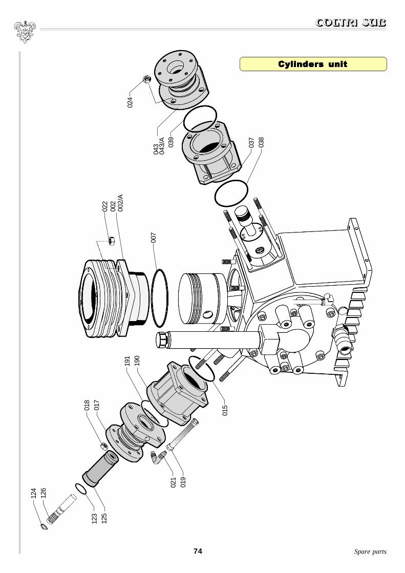
74
126
124
125
123
017
018
015
019
021
002
002/
A
022
007
038
037
039
043
043/
A
190
191
024
Spare parts
Cylinders unitCylinders unitCylinders unitCylinders unitCylinders unit

75Spare parts
Cylinders unitCylinders unitCylinders unitCylinders unitCylinders unit
POS. CODE DESCRIPTION002 13-01-0002 FIRST STAGE 88 mm. CYLINDER002/A 16-01-0002 FIRST STAGE 95 mm. CYLINDER007 13-01-0007 FIRST STAGE CYLINDER O-RING015 13-00-0015 THIRD STAGE CYLINDER O-RING017 13-02-0017 THIRD STAGE GUIDING CYLINDER018 13-00-0018 8 mm. BOLT019 13-00-0019 LUBRICATION INDICATOR PIPE021 13-00-0021 CORNER ¹/8 PIPE FITTING 8 mm. RILSAN022 13-00-0018 8 mm. NUT024 13-00-0018 8 mm. NUT037 13-02-0037 SECOND STAGE 60 mm. GUIDING CYLINDER038 13-00-0015 GUIDING CYLINDER O-RING 039 13-00-0039 SECOND STAGE CYLINDER O-RING 043 13-02-0043 SECOND STAGE 36 mm. CYLINDER043/A 16-02-0043 SECOND STAGE 38 mm. CYLINDER123 13-03-0123 3rd STAGE VITON O-RING 124 13-03-0124 SET OF 3rd STAGE PISTON RINGS125 13-03-0125 14 mm. THIRD STAGE CYLINDER126 13-03-0126 14 mm. THIRD STAGE PISTON190 13-03-0190 THIRD STAGE 60 mm GUIDING CYLINDER191 13-00-0039 THIRD STAGE GUIDING CYLINDER O-RING

045
051047
049056
048195
He
ad
un
itH
ea
d u
nit
He
ad
un
itH
ea
d u
nit
He
ad
un
it
76
034033032
031
028029030
035
025027
020
003003/A
004005
006012
010009
011013
041026 014
046196044
Sp
are
pa
rts
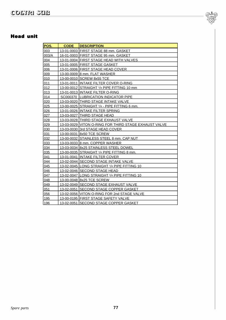
77Spare parts
Head unitHead unitHead unitHead unitHead unit
POS. CODE DESCRIPTION003 13-01-0003 FIRST STAGE 88 mm. GASKET003/A 16-01-0003 FIRST STAGE 95 mm. GASKET004 13-01-0004 FIRST STAGE HEAD WITH VALVES005 13-01-0005 FIRST STAGE GASKET006 13-01-0006 FIRST STAGE HEAD COVER009 13-00-0009 8 mm. FLAT WASHER010 13-00-0010 SCREW 8x55 TCE011 13-01-0011 INTAKE FILTER COVER O-RING012 13-00-0012 STRAIGHT ¹/4 PIPE FITTING 10 mm013 13-01-0013 INTAKE FILTER O-RING014 SC000370 LUBRICATION INDICATOR PIPE020 13-03-0020 THIRD STAGE INTAKE VALVE025 13-00-0025 STRAIGHT ¹/4 - PIPE FITTING 6 mm.026 13-01-0026 INTAKE FILTER SPRING027 13-03-0027 THIRD STAGE HEAD028 13-03-0028 THIRD STAGE EXHAUST VALVE029 13-03-0029 VITON O-RING FOR THIRD STAGE EXHAUST VALVE030 13-03-0030 3rd STAGE HEAD COVER031 13-00-0031 8x50 TCE SCREW032 13-00-0032 STAINLESS STEEL 8 mm. CAP NUT033 13-03-0033 8 mm. COPPER WASHER034 13-03-0034 8x25 STAINLESS STEEL DOWEL035 13-00-0035 STRAIGHT ¹/4 PIPE FITTING 8 mm.041 13-01-0041 INTAKE FILTER COVER044 13-02-0044 SECOND STAGE INTAKE VALVE045 13-02-0045 LONG STRAIGHT ¹/4 PIPE FITTING 10046 13-02-0046 SECOND STAGE HEAD047 13-02-0047 LONG STRAIGHT ¹/4 PIPE FITTING 10048 13-00-0048 8x25 TCE SCREW049 13-02-0049 SECOND STAGE EXHAUST VALVE051 13-02-0051 SECOND STAGE COPPER GASKET056 13-02-0056 VITON O-RING FOR 2nd STAGE VALVE195 13-00-0195 FIRST STAGE SAFETY VALVE196 13-02-0051 SECOND STAGE COPPER GASKET

080081
079082
Co
olin
g p
ipe
sC
oo
ling
pip
es
Co
olin
g p
ipe
sC
oo
ling
pip
es
Co
olin
g p
ipe
s
78
036089
083
084
186086
185087
077074
135134
138
136140
139
133075
141
142
137023
085087
197Sp
are
pa
rts
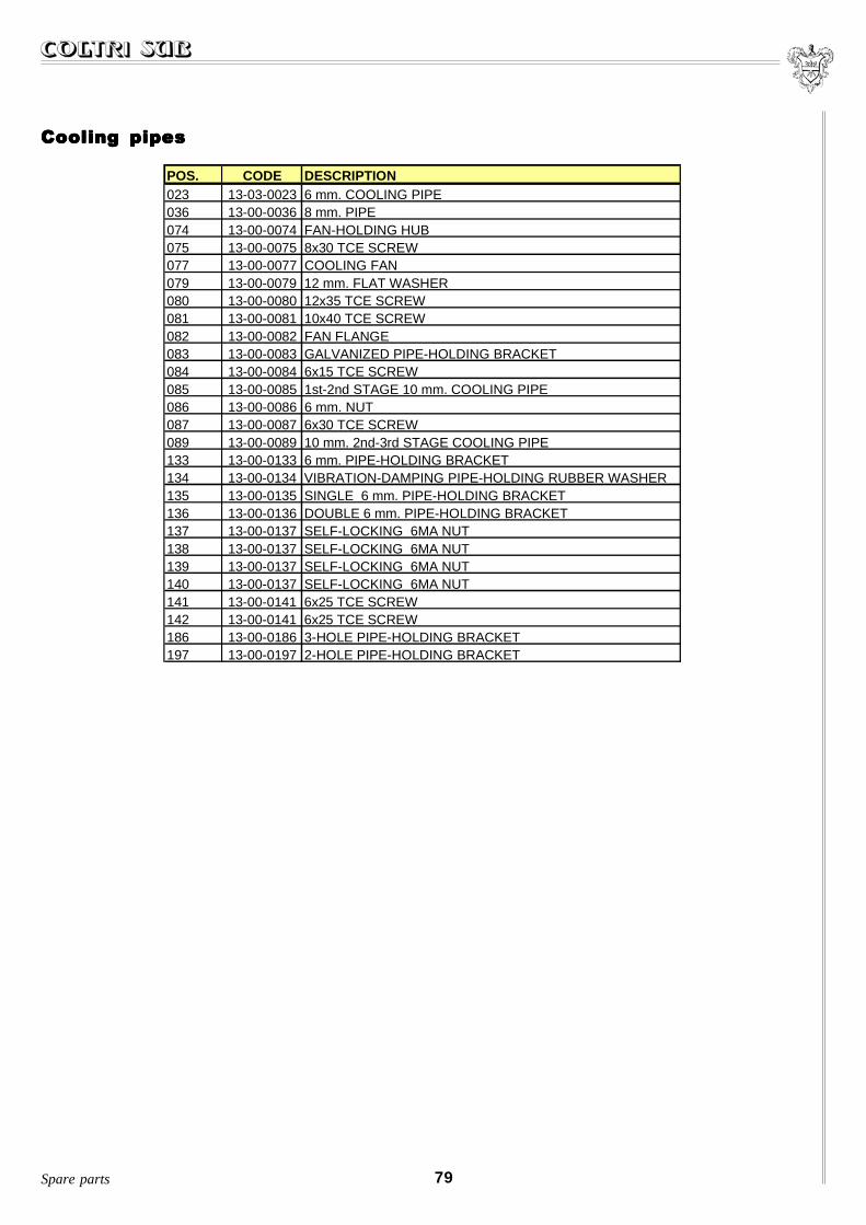
79Spare parts
Cooling pipesCooling pipesCooling pipesCooling pipesCooling pipes
POS. CODE DESCRIPTION023 13-03-0023 6 mm. COOLING PIPE036 13-00-0036 8 mm. PIPE074 13-00-0074 FAN-HOLDING HUB075 13-00-0075 8x30 TCE SCREW077 13-00-0077 COOLING FAN079 13-00-0079 12 mm. FLAT WASHER080 13-00-0080 12x35 TCE SCREW081 13-00-0081 10x40 TCE SCREW082 13-00-0082 FAN FLANGE083 13-00-0083 GALVANIZED PIPE-HOLDING BRACKET084 13-00-0084 6x15 TCE SCREW085 13-00-0085 1st-2nd STAGE 10 mm. COOLING PIPE086 13-00-0086 6 mm. NUT087 13-00-0087 6x30 TCE SCREW089 13-00-0089 10 mm. 2nd-3rd STAGE COOLING PIPE133 13-00-0133 6 mm. PIPE-HOLDING BRACKET134 13-00-0134 VIBRATION-DAMPING PIPE-HOLDING RUBBER WASHER135 13-00-0135 SINGLE 6 mm. PIPE-HOLDING BRACKET136 13-00-0136 DOUBLE 6 mm. PIPE-HOLDING BRACKET137 13-00-0137 SELF-LOCKING 6MA NUT138 13-00-0137 SELF-LOCKING 6MA NUT139 13-00-0137 SELF-LOCKING 6MA NUT140 13-00-0137 SELF-LOCKING 6MA NUT141 13-00-0141 6x25 TCE SCREW142 13-00-0141 6x25 TCE SCREW186 13-00-0186 3-HOLE PIPE-HOLDING BRACKET197 13-00-0197 2-HOLE PIPE-HOLDING BRACKET

80
153152
156155154
158
097157
159160
198
188
187
189
Spare parts
Filtering systemFiltering systemFiltering systemFiltering systemFiltering system

81Spare parts
Filtering systemFiltering systemFiltering systemFiltering systemFiltering system
POS. CODE DESCRIPTION097 13-00-0097 CLEANER FILTER152 13-00-0152 VITE 8x30 TCE153 13-00-0153 VITE 8x12 TCE154 13-00-0154 UPPER FILTER CAP155 13-00-0155 FILTER CAP O-RING156 13-00-0156 INTERNAL FILTER CAP157 13-00-0155 FILTER CAP O-RING158 13-00-0158 FILTER CARTRIDGE O-RING159 13-00-0155 FILTER CAP O-RING 160 13-00-0160 LOWER FILTER CAP187 13-00-0187 MESH DISK DIAM. 39 mm.188 13-00-0188 FILTER CARTRIDGE INTERNAL SPRING189 13-00-0189 FELT DISK DIAM. 40 mm198 13-00-0144 CORNER ¹/8 PIPE FITTING 6 mm.
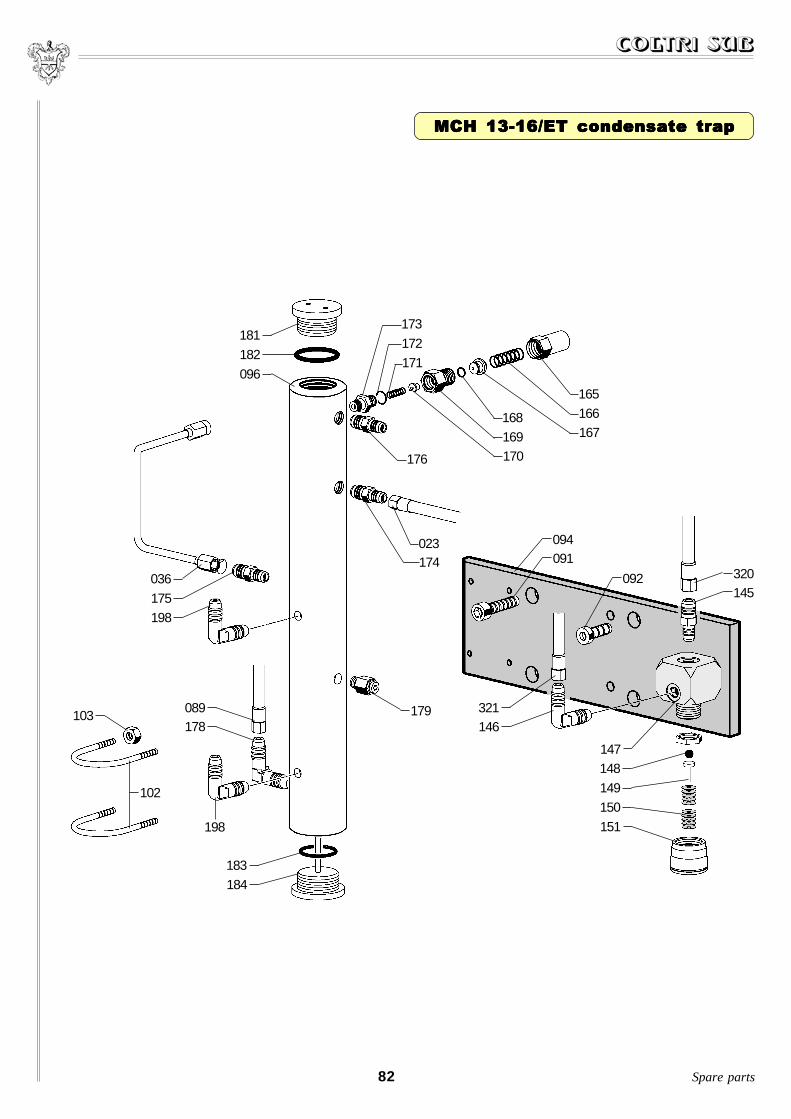
82
MCH 13-16/ET condensate trapMCH 13-16/ET condensate trapMCH 13-16/ET condensate trapMCH 13-16/ET condensate trapMCH 13-16/ET condensate trap
094091
092 320145
148
149
150
151198
183
184
102
103
036
175
174
176
181
182
096
165
166
023
173
172
171
321146
147
167168
169170
089178
179
198
Spare parts

83
MCH 13-16/ET condensate trapMCH 13-16/ET condensate trapMCH 13-16/ET condensate trapMCH 13-16/ET condensate trapMCH 13-16/ET condensate trap
Spare parts
POS. CODE DESCRIPTION023 13-03-0023 6 mm. COOLING PIPE036 13-00-0036 8 mm. PIPE089 13-00-0089 10 mm. 2nd-3rd STAGE COOLING PIPE091 13-00-0048 8x25 TCE SCREW092 13-00-0092 LOWERED 8x20 TCE SCREW094 13-00-0094 FILTER-HOLDING PLATE096 13-00-0096 CONDENSATE TRAP102 13-00-0102 TRAP-HOLDING BRACKET103 13-00-0018 8 mm. NUT145 13-00-0025 STRAIGHT ¹/4 - PIPE FITTING 6 mm.146 13-00-0146 CORNER ¹/4 - PIPE FITTING 6 mm.147 13-00-0147 V.M.P. BODY148 13-00-0148 V.M.P. STEEL BALL149 13-00-0149 SMALL V.M.P. PISTON150 13-00-0150 SET OF BELLEVILLE WASHERS151 13-00-0151 V.M.P. CAP165 13-00-0165 SAFETY VALVE ADJUSTMENT COVER166 13-00-0166 SAFETY VALVE SPRING167 13-00-0167 SMALL SAFETY VALVE PISTON168 13-00-0168 SMALL S.V. PISTON O-RING 169 13-00-0169 SAFETY VALVE BODY170 13-00-0170 NYLON SAFETY VALVE SEAT171 13-00-0171 SAFETY VALVE SEAT SPRING172 13-00-0172 SAFETY VALVE O-RING 173 13-00-0173 SAFETY VALVE CONNECTOR174 13-00-0174 STRAIGHT ¹/8 PIPE FITTING 6175 13-00-0174 STRAIGHT ¹/8 PIPE FITTING 6 176 13-00-0174 STRAIGHT ¹/8 PIPE FITTING 6 178 13-00-0178 CORNER ¹/4 - PIPE FITTING 10 mm.179 13-03-0179 SECOND STAGE SAFETY VALVE181 13-00-0181 UPPER TRAP/FILTER TRAP CAP182 13-00-0182 UPPER TRAP CAP O-RING183 13-00-0182 TRAP CAP O-RING184 13-00-0184 LOWER TRAP CAP198 13-00-0144 CORNER ¹/8 - PIPE FITTING 6 mm.320 13-04-0320 HP 6 mm. PIPE321 13-04-0321 HP 800 mm. PIPE

84
096
MCH 26-32/ETMCH 26-32/ETMCH 26-32/ETMCH 26-32/ETMCH 26-32/ET condensate trapcondensate trapcondensate trapcondensate trapcondensate trap
182
181
036175
198
089178
103
102
198
183184
179
023174
091094
092
176
171
172173
168169170
165166167
148149150151
147
146 215069145322
Spare parts

85
MCH 26-32/ET condensate trapMCH 26-32/ET condensate trapMCH 26-32/ET condensate trapMCH 26-32/ET condensate trapMCH 26-32/ET condensate trap
Spare parts
POS. CODE DESCRIPTION023 13-03-0023 6 mm. COOLING PIPE036 13-00-0036 8 mm. PIPE069 13-04-0226 HP 300 mm. PIPE089 13-00-0089 10 mm. 2nd-3rd STAGE COOLING PIPE091 13-00-0048 8x25 TCE SCREW092 13-00-0092 LOWERED 8x20 TCE SCREW094 13-00-0094 FILTER-HOLDING PLATE096 13-00-0096 CONDENSATE TRAP102 13-00-0102 TRAP-HOLDING BRACKET103 13-00-0018 8 mm. NUT145 13-00-0025 STRAIGHT ¹/4 - PIPE FITTING 6 mm.146 13-00-0146 CORNER ¹/4 - PIPE FITTING 6 mm.147 13-00-0147 V.M.P. BODY148 13-00-0148 V.M.P. STEEL BALL149 13-00-0149 SMALL V.M.P. PISTON150 13-00-0150 SET OF BELLEVILLE WASHERS151 13-00-0151 V.M.P. CAP165 13-00-0165 SAFETY VALVE ADJUSTMENT COVER166 13-00-0166 SAFETY VALVE SPRING167 13-00-0167 SMALL SAFETY VALVE PISTON168 13-00-0168 SMALL S.V. PISTON O-RING 169 13-00-0169 SAFETY VALVE BODY170 13-00-0170 NYLON SAFETY VALVE SEAT171 13-00-0171 SAFETY VALVE SEAT SPRING172 13-00-0172 SAFETY VALVE O-RING 173 13-00-0173 SAFETY VALVE CONNECTOR174 13-00-0174 STRAIGHT ¹/8 PIPE FITTING 6175 13-00-0174 STRAIGHT ¹/8 PIPE FITTING 6 176 13-00-0174 STRAIGHT ¹/8 PIPE FITTING 6 178 13-00-0178 CORNER ¹/4 PIPE FITTING 10 mm. 179 13-03-0179 SECOND STAGE SAFETY VALVE181 13-00-0181 UPPER TRAP/FILTER TRAP CAP181/A 13-00-181A UPPER ¹/8 HOLE TRAP CAP182 13-00-0182 UPPER TRAP CAP O-RING183 13-00-0182 UPPER TRAP CAP O-RING184 13-00-0184 LOWER TRAP CAP198 13-00-0144 CORNER ¹/8 - PIPE FITTING 6 mm.215 13-04-0215 HP 400 mm. PIPE322 13-04-0430 ALUMINIUM BLOCK

300
302
250
301
MC
H 1
3-1
6/E
TM
CH
13
-16
/ET
MC
H 1
3-1
6/E
TM
CH
13
-16
/ET
MC
H 1
3-1
6/E
T
86
253
252
272
251
279
254255
222
221
224
233 234235
256
257276
258
230231
217
310311312
309308
307208
209
211
210210/A
232
Sp
are
pa
rts

87
MCH 13-16/ETMCH 13-16/ETMCH 13-16/ETMCH 13-16/ETMCH 13-16/ET
Spare parts
POS. CODE DESCRIPTION208 13-04-0208 COMPLETE LOCK209 13-04-0209 SWITCHBOARD PANEL210 SC000310 280 BAR PRESSURE SWITCH210/A SC000315 330 BAR PRESSURE SWITCH211 13-04-0211 PRESSURE GAUGE WITH FLANGE217 13-04-0217 RELOAD RAMP ALUMINIUM BLOCK221 13-04-0221 LP CONDENSATION DISCHARGE SOLENOID VALVE222 13-04-0222 HP CONDENSATION DISCHARGE SOLENOID VALVE224 13-04-0224 CONDENSATION DISCHARGE ALUMINIUM BLOCK230 13-04-0230 OIL DISCHARGE COCK231 13-04-0231 ¹/2" OIL DISCHARGE CAP232 13-00-0164 CONDENSATE DISCHARGE HANDWHEEL233 13-00-0163 CONDENSATE DISCHARGE SPRING234 13-00-0162 NYLON CONDENSATE DISCHARGE235 13-00-0161 CONDENSATE DISCHARGE TAP CASING250 13-04-0400 COMPACT FRONT PANEL251 13-04-0401 COMPACT LEFT-HAND SIDE PANEL252 13-04-0402 COMPACT REAR PANEL253 13-04-0403 COMPACT RIGHT-HAND SIDE PANEL254 13-04-0404 COMPACT UPPER INSTRUMENT PANEL255 13-04-0405 COMPACT UPPER PANEL256 13-04-0406 MOTOR-COMPRESSOR SUPPORT257 13-04-0407 BASE258 13-04-0408 COMPACT OIL LEVEL PLATE272 13-04-0272 CONDENSATION DISCHARGE CAN COMPLETE WITH PIPE FITTINGS276 16-05-030 VIBRATION-DAMPING SUPPORT279 13-04-0279 VIBRATION DAMPNER WITH DOUBLE ATTACHMENT300 SC000450 BC INT COCK301 SC000460 BC DIN 200 BAR COCK301/A SC000470 BC DIN 300 BAR COCK302 13-04-238 HP 1200 mm. PIPE307 13-04-0203 OFF PLATE308 13-04-0204 ON PLATE309 13-04-0205 MANUAL PURGE PLATE310 13-04-0202 YELLOW CONDENSATION DISCHARGE BUTTON311 13-04-0201 GREEN START BUTTON312 13-04-0200 RED STOP BUTTON

88
279
272
325
326
329
328
327
330
331
332
333
335
336
334
337
MCH 26-32/ETMCH 26-32/ETMCH 26-32/ETMCH 26-32/ETMCH 26-32/ET
Spare parts

89
MCH 26-32/ETMCH 26-32/ETMCH 26-32/ETMCH 26-32/ETMCH 26-32/ET
Spare parts
POS. CODE DESCRIPTION272 13-04-0272 CONDENSATION DISCHARGE CAN COMPLETE WITH PIPE FITTINGS279 13-04-0279 VIBRATION DAMPNER WITH DOUBLE ATTACHMENT325 13-04-0409 PUMP UNITS REAR PANEL326 13-04-0410 COMPACT UPPER PANEL327 13-04-0411 OIL REFILL CAP B328 13-04-0412 OIL REFILL CAP A329 13-04-0413 COMPACT STAY BOLT M6330 13-04-0414 COMPACT LEFT-HAND SIDE PANEL331 13-04-0415 LEFT INTERNAL CONVEYOR332 13-04-0416 RIGHT INTERNAL CONVEYOR333 13-04-0417 MOTOR-COMPRESSOR SUPPORT334 13-04-0418 UPPER INTERNAL CONVEYOR335 13-04-0419 COMPACT REAR PANEL336 13-04-0420 COMPACT RIGHT-HAND SIDE PANEL337 13-04-0421 BASE

217216
219
220
242225
223222
221
224
MC
H 2
6-3
2/E
T
MC
H 2
6-3
2/E
T
MC
H 2
6-3
2/E
T
MC
H 2
6-3
2/E
T
MC
H 2
6-3
2/E
T fro
nt p
an
el
fron
t pa
ne
lfro
nt p
an
el
fron
t pa
ne
lfro
nt p
an
el
90
228227
242
236
233234
235232
231
230
229
240239
210210/A
211
229
202
201
200
338
208
205
204
203
207
209
237
213
215
216
236
238
233234
235
232
Sp
are
pa
rts

91
MCH 26-32/ET MCH 26-32/ET MCH 26-32/ET MCH 26-32/ET MCH 26-32/ET front panelfront panelfront panelfront panelfront panel
Spare parts
POS. CODE DESCRIPTION200 13-04-0200 RED STOP BUTTON201 13-04-0201 GREEN START BUTTON202 13-04-0202 YELLOW CONDENSATION DISCHARGE BUTTON203 13-04-0203 OFF PLATE204 13-04-0204 ON PLATE205 13-04-0205 MANUAL PURGE PLATE207 13-04-0207 HOUR COUNTER208 13-04-0208 COMPLETE LOCK209 13-04-0209 SWITCHBOARD PANEL210 SC000310 280 BAR PRESSURE SWITCH210/A SC000315 330 BAR PRESSURE SWITCH211 13-04-0211 PRESSURE GAUGE WITH FLANGE213 13-04-0213 HP 400 mm. PRESSURE GAUGE HOLDING MICROTUBE215 13-04-0215 HP 400 mm. PIPE216 13-00-0174 STRAIGHT ¹/8 PIPE FITTING 6 mm.217 13-04-0217 RELOAD RAMP ALUMINIUM BLOCK219 13-04-0219 HP 400 mm. PIPE220 13-04-0220 HP 1000 mm. PIPE221 13-04-0221 LP CONDENSATION DISCHARGE SOLENOID VALVE222 13-04-0222 HP CONDENSATION DISCHARGE SOLENOID VALVE223 13-04-0223 CONNECTOR WITH SOLENOID VALVE FILTER224 13-04-0224 CONDENSATION DISCHARGE ALUMINIUM BLOCK225 13-04-0225 ¹/4 GAS - ¹/4 NPT PIPE FITTING227 13-04-0227 FILTER REINFORCEMENT PLATE228 13-00-0018 8 mm. NUT229 13-04-0229 LVO 127/10 OIL LEVEL230 13-04-0230 OIL DISCHARGE COCK231 13-04-0231 ¹/2" OIL DISCHARGE CAP232 13-00-0164 CONDENSATE DISCHARGE HANDWHEEL233 13-00-0163 CONDENSATE DISCHARGE SPRING234 13-00-0162 NYLON CONDENSATE DISCHARGE235 13-00-0161 CONDENSATE DISCHARGE TAP CASING236 13-00-0093 FILTER-HOLDING BRACKET237 13-00-0174 STRAIGHT 6 mm. PIPE ¹/8 FITTING238 13-04-0238 HP 1200 mm. PIPE239 SC000470 BC DIN 200 BAR COCK239/A SC000460 BC DIN 300 BAR COCK240 SC000450 BC INT COCK242 13-00-0174 STRAIGHT 6 mm. PIPE ¹/8 FITTING338 13-04-0422 26-32/ET FRONT PANEL

AEROTECNICA COLTRI S.r.l.Registered office: Via Rio Ponale, 7 - 25010 Rivoltella di Desenzano D/Garda - BRESCIA - ITALY
Factory: Via Colli Storici, 177 - 25010 San Martino della Battaglia - BRESCIA - ITALYTel. +39 030 9910297-9910301 - Fax +39 030 9910283
e-mail: [email protected] Internet: http://www.coltrisub.it