special: international edition - gomaco godbersen accounting sharon k. godbersen manufacturing grant...
TRANSCRIPT

Vol. 35, No. 2
Special:International Edition

GOMACO World is published by GOMACO Corporation to inform readers of applied constructiontechnology utilizing GOMACO equipment as well as innovations and concerns in the constructionindustry throughout the world. All rights reserved. The contents of this publication may not bereproduced either in whole or in part without the consent of copyright owner. Printed in U.S.A. © 2007 GOMACO Corporation (07 CFX). All stories written by the editor unless otherwise noted.
Address all communications to GOMACO World Editor. If you do not receive GOMACO World,and would like a complimentary subscription, please contact GOMACO Corporation, PO Box 151, Ida Grove, IA, 51445, USA, 712-364-3347 or e-mail [email protected].
Vol. 35, No. 2
GOMACO
President and CEO Gary L. Godbersen
Vice PresidentsWorldwide Sales and Marketing
Kent GodbersenAccounting Sharon K. GodbersenManufacturing Grant Godbersen
Administration & Finance Richard E. SmithEngineering & Service Dwayne SalmonResearch and Development Kevin Klein
General Manager of ManufacturingDan Soellner
Sales United States and CanadaSales Manager Bob Leonard
Sales Coordinator Brad ZobelAssistant Sales Coordinator Mike Leinbaugh
United States and CanadaDistrict Managers
Brad Barkema – N. CentralJim Hayward – Western
Kendall Kelly – S.W.Vinnie Miller – S.E.
Len Rettinger – N.E./Central
International SalesDirector Bryan Schwartzkopf
Coordinator Randy Bean
International Regional ManagerTim Nash – Asia Pacific
Steve Bowman – Latin America
GOMACO International Ltd.Managing Director Rory Keogh
Service DepartmentManager Dennis Ernst
Service Desk DeWayne Krayenhagen
Parts Manager John KallinParts Desk Dan Ellerbusch,
Jeff Stevenson & Dean O’Tool
GOMACO University Training CenterDirector Dennis Clausen
Assistant Director Rod Schneider
GOMACO World is produced by theGOMACO Advertising Department.
Manager Randy BachMarketing Coordinator Micki RettingerGOMACO World Editor Kelly Krueger
Director of Sales Support Gayle HarrisonCommunications Specialist Thomas R. GrellCommunications Specialist Bobbi L. WonderAdvertising Coordinator Carrie J. Odgaard
Photo Lab Don Poggensee
Please visit our Web site at http://www.gomaco.comGOMACO World magazine at http://www.gomaco.com/gomacoworldGOMACO World Editor Kelly Krueger at [email protected]
7 11 14 16
3 INTRODUCING A NEW SYSTEM TO THE CZECH REPUBLIC– Skanska DS a.s. (Cover photo by Tom Bell HW-050609 D12)
7 COMMANDER III VERSATILITY ROCKS!– DMC Concrete Developments
10 PAVING ROADWAY THROUGH TUNNELS IN JAPAN– Taisei-Rotec Corporation & K-Con Company Ltd.
11 34 PAVING PASSES FOR A GHP-2800– Betonac nv
14 GT-3600 & STRINGLESS BARRIER IN SLOVAKIA– Doprastav, a.s.
16 IT’S NOT YOUR ORDINARY CANAL PAVER...– The All-American Canal Project
20 GOMACO INTRODUCES NEW TECHNOLOGY– Bauma 2007 in Munich, Germany
21 GOMACO EQUIPMENT IS CONTRACTOR’S CHOICE
22 AROUND THE WORLD

3
The Czech Republic isundertaking a massive road-buildingeffort to improve the quality of thecountry’s roadways. Several differentprojects are underway that willimprove traveling conditions for localcitizens, truckers and tourists.
Skanska DS a.s., based out ofBrno, Czech Republic, has been atwork on two of those major road-building projects, one onHighway D1 near Vyskov,and a second on HighwayD11 near Hradec Králové.They’ll be slipform paving atotal of 58 km (36 mi) ofnew roadway by the timeboth projects are completed.
The Czech Republic alsospecifies two-lift pavementon some of their projects, ora roadway made up of two
layers and two different concrete mixdesigns. It was a requirement onSkanska’s first project, Highway D1.The typical method for two-layerpavement in the country requires twoseparate machines. A paver leadslaying down the first layer of concrete,a placer/spreader follows spreadingout the second concrete mix and asecond paver follows behind paving
the top layer of concrete with a mid-mount dowel bar insertion system.
Officials from Skanska hadobserved that version of two-liftpaving and wanted a more efficientway for their project. They begandiscussions with GOMACO about aGP-4000 paver with a two-lift systemincorporated on a single paver.
GOMACO’s two-lift system fitsunderneath the paver. Noextra extensions or pavingmachines are needed. It was aconcept that intriguedSkanska, and they ultimatelypurchased a GP-4000 with thetwo-lift paving system for theHighway D1 project. Thepaver is also equipped withan In-the-Pan Dowel BarInserter (IDBI) and Leicastringless control system.
Introducing a New SlipformingSystem to the Czech Republic
Skanska’s GP-4000 with two-lift paving system, IDBI and stringless control system slipforms a new highway in the Czech Republic.
Pho
to b
y To
m B
ell
HW
-050
606
D16
GOMACO’s compact two-lift paving system with IDBI fitsunderneath the standard framework of the GP-4000 paver.

4
Highway D1: Praha–OstravaThe new section of Highway D1 runs
between Vyskov and Morice, andinvolved building 16 km (9.9 mi) of two-lane roadway. Specifications on theproject called for a 200 mm (7.9 in) thickbottom layer with a 100 mm (3.9 in)thick top layer for a total thickness of300 mm (11.8 in).
“The two layers are a generalrequirement for this highway,” JosefRichter, Production/Technical Managerof Skanska, said. “The differencebetween the two concrete mix designs is mostly the size and quality of theaggregate. The upper layer has amaximum aggregate size of 22 mm (0.9 in), while the bottom has amaximum of 32 mm (1.25 in).
“The mix contains both airentrainment and plasticizers. Aeration isthe basic requirement for frost resistanceand to resist against chemical sanding.”
One concrete batch plant was usedfor both concrete mix designs. Concretewas mixed at a 2:1 batching ratio, withtwo loads of the bottom concrete mixbatched versus just one of the thinnertop layer.
Concrete was hauled to the pavingsite by dump trucks with a haulingcapacity of 25 tons. Trucks dumpeddirectly onto the grade for the bottomlayer or lift of the roadway. Augers onthe front paving pan spread the material,vibration is applied consolidating thebottom layer and the second moldfinishes the top layer of concrete.
An excavator running in front of thepaver emptied concrete out of the trucksfor the top layer. The excavator placesthe concrete into a specially designedhopper on the front of the GP-4000paver. The concrete is conveyed from thehopper into a top-layer paving chamberand is spread with an auger across thewidth of the pavement. The vibrators inthe top layer paving chamber runparallel to the face of the paving pan.Their placement ensures the top layer ofconcrete is properly consolidatedwithout mixing it into the bottom layerof concrete and changing both mixdesigns. Vibrators placed along thewidth of the pan provide properconsolidation to the edge.
The two layers are slipformedsimultaneously underneath the length ofthe paver. The arrangement guarantees agood bond between the two layersbecause of the freshness of the twolayers of concrete. Skanska is achieving an average smoothness reading of only 2 mm (0.08 in) per four meters
(13.1 ft) on the Planograph testing system, half of the project’s 4 mm (0.16 in) specification.
The two-lift paving project near Vyskov required a 200 mm (7.9 in) thick bottom layerwith 100 mm (3.9 in) top layer for a total roadway thickness of 300 mm (11.8 in).
The IDBI inserts 40 bars, 250 mm (9.8 in) apart, across the width of the paving pass.
Pho
to b
y To
m B
ell
HW
-050
609
D3
Pho
to b
y K
elly
Kru
eger
H
W-1
0040
8 D
21
Pho
to b
y K
en T
ipp
ie
HW
-100
416
D9
Pho
to b
y R
afal
Pig
ula
HW
-050
617
D25

5
Paving production averaged 400 meters (1312 ft) per day while paving the two-lift project.
An excavator was used to place the top layer concrete mix design into the paver’s hopper.The bottom layer’s concrete was dumped directly on the ground, in front of the GP-4000.
The IDBI is attached to the paverbehind the second pan and inserts barsfor the joints in the new roadway. Fortybars with a 25 mm (1 in) diameter and500 mm (19.7 in) length were insertedevery six meters (19.7 ft) across thewidth of the pavement. The bars were placed 250 mm (9.8 in) apart and150 mm (5.9 in) deep into the slab.
“The bar placement accuracy wasperfect,” Richter said. “Checks wereconducted to test the accuracy of theplacement and the tests showed goodresults every time.”
Paving widths varied between 10.75 meters (35.3 ft) and 12.25 meters(40.2 ft) depending on projectspecifications. Producing the twodifferent mix designs from a single plant with double drums limited theirdaily production, which averagedapproximately 400 meters (1312 ft) perday.
Highway D11: Praha–Hradec Králové
Skanska’s second project with theirGP-4000 has them at work building 42 km (26 mi) of Highway D11connecting Hradec Králové toPodûbrady in the Czech Republic.Skanska removed their two-lift pavingfeature, but left the IDBI on their paver.It was just a matter of removing the firstlift or the bottom paving pan of the two-lift system.
Bar insertion requirements aresimilar to the D1 project. Forty bars areinserted 120 mm (4.7 in) deep into thenew roadway every six meters (19.7 ft).
The Leica 3D machine control systemis once again at work on the project. Twoprisms are mounted on the paver, whichare tracked by Leica robotic totalstations. The total stations constantlyfeed machine position coordinates to the3D controller via a radio link. The paveris also equipped with front and rearslope sensors which measure themachine’s cross slope. The informationfrom the total stations and the slopesensors is used by the 3D controller tocalculate final machine position andorientation, and in turn feed controlsignal information to the main machinecontroller.
Three total stations are at work onthe projects. Two are used to guide thepaver while the third total stationconducts as-built checks behind thepaver. The as-built checks measure theline and level of the new concrete
The GOMACO GSI follows the paver and measures the smoothness of the new roadway.
Pho
to b
y R
afal
Pig
ula
HW
-050
619
D25
Pho
to b
y K
elly
Kru
eger
H
W-1
0040
7 D
19P
hoto
by
John
Bow
den
H
W-0
8060
3 D
2
6
roadway and provide instant feedback onthe accuracy of the new slab.
The third total station can also beused for leap frogging, which is theprocess of switching from one totalstation to the next when one becomes toofar away from the paver.
“The system is very modern and aneffective method eliminating the humanfactor influencing the classical ‘stringlineguidance’ method,” Richter said. “It isvery economical and effective and wewant to apply it to all of our pavers.”
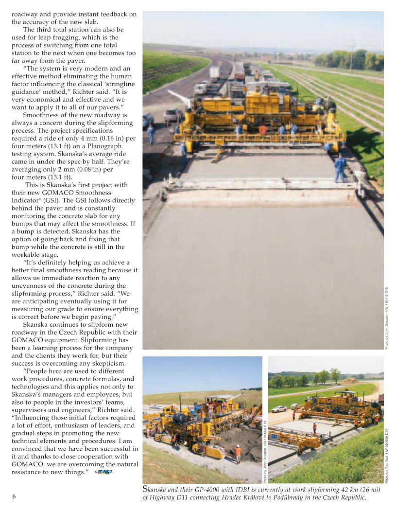
Smoothness of the new roadway isalways a concern during the slipformingprocess. The project specificationsrequired a ride of only 4 mm (0.16 in) perfour meters (13.1 ft) on a Planographtesting system. Skanska’s average ridecame in under the spec by half. They’reaveraging only 2 mm (0.08 in) per four meters (13.1 ft).
This is Skanska’s first project withtheir new GOMACO SmoothnessIndicator® (GSI). The GSI follows directlybehind the paver and is constantlymonitoring the concrete slab for anybumps that may affect the smoothness. Ifa bump is detected, Skanska has theoption of going back and fixing thatbump while the concrete is still in theworkable stage.
“It’s definitely helping us achieve abetter final smoothness reading because itallows us immediate reaction to anyunevenness of the concrete during theslipforming process,” Richter said. “Weare anticipating eventually using it formeasuring our grade to ensure everythingis correct before we begin paving.”
Skanska continues to slipform newroadway in the Czech Republic with theirGOMACO equipment. Slipforming hasbeen a learning process for the companyand the clients they work for, but theirsuccess is overcoming any skepticism.
“People here are used to differentwork procedures, concrete formulas, andtechnologies and this applies not only toSkanska’s managers and employees, butalso to people in the investors’ teams,supervisors and engineers,” Richter said.“Influencing those initial factors requireda lot of effort, enthusiasm of leaders, andgradual steps in promoting the newtechnical elements and procedures. I amconvinced that we have been successful init and thanks to close cooperation withGOMACO, we are overcoming the naturalresistance to new things.”
Skanska and their GP-4000 with IDBI is currently at work slipforming 42 km (26 mi)of Highway D11 connecting Hradec Králové to Podûbrady in the Czech Republic.
Pho
to b
y Jo
hn B
owd
en
HW
-110
419
D15
Pho
to b
y To
m B
ell
HW
-050
608
D27
Pho
to b
y Jo
hn B
owd
en
HW
-080
604
D19
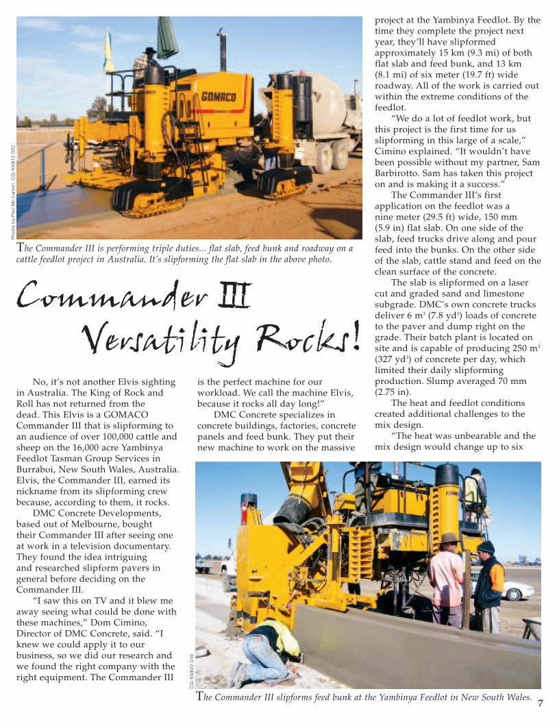
No, it’s not another Elvis sightingin Australia. The King of Rock andRoll has not returned from the dead. This Elvis is a GOMACOCommander III that is slipforming toan audience of over 100,000 cattle andsheep on the 16,000 acre YambinyaFeedlot Tasman Group Services inBurraboi, New South Wales, Australia.Elvis, the Commander III, earned itsnickname from its slipforming crewbecause, according to them, it rocks.
DMC Concrete Developments,based out of Melbourne, bought their Commander III after seeing oneat work in a television documentary.They found the idea intriguing and researched slipform pavers ingeneral before deciding on theCommander III.
“I saw this on TV and it blew meaway seeing what could be done withthese machines,” Dom Cimino,Director of DMC Concrete, said. “Iknew we could apply it to ourbusiness, so we did our research andwe found the right company with theright equipment. The Commander III
is the perfect machine for ourworkload. We call the machine Elvis,because it rocks all day long!”
DMC Concrete specializes inconcrete buildings, factories, concretepanels and feed bunk. They put theirnew machine to work on the massive
77
project at the Yambinya Feedlot. By thetime they complete the project nextyear, they’ll have slipformedapproximately 15 km (9.3 mi) of bothflat slab and feed bunk, and 13 km (8.1 mi) of six meter (19.7 ft) wideroadway. All of the work is carried outwithin the extreme conditions of thefeedlot.
“We do a lot of feedlot work, butthis project is the first time for usslipforming in this large of a scale,”Cimino explained. “It wouldn’t havebeen possible without my partner, SamBarbirotto. Sam has taken this projecton and is making it a success.”
The Commander III’s firstapplication on the feedlot was a nine meter (29.5 ft) wide, 150 mm (5.9 in) flat slab. On one side of theslab, feed trucks drive along and pourfeed into the bunks. On the other sideof the slab, cattle stand and feed on theclean surface of the concrete.
The slab is slipformed on a lasercut and graded sand and limestonesubgrade. DMC’s own concrete trucksdeliver 6 m3 (7.8 yd3) loads of concreteto the paver and dump right on thegrade. Their batch plant is located onsite and is capable of producing 250 m3
(327 yd3) of concrete per day, whichlimited their daily slipformingproduction. Slump averaged 70 mm(2.75 in).
The heat and feedlot conditionscreated additional challenges to themix design.
“The heat was unbearable and themix design would change up to six
The Commander III is performing triple duties... flat slab, feed bunk and roadway on acattle feedlot project in Australia. It’s slipforming the flat slab in the above photo.
The Commander III slipforms feed bunk at the Yambinya Feedlot in New South Wales.
Pho
tos
by
Pau
l Mc
Larn
on
CG
-100
612
D22
CG
-100
622
D16

times a day because of extremeconditions,” Cimino said. “We alsowere adding an air mixture that wasneeded for durability. The additivekeeps the concrete from absorbingthe cattle’s urine and helps cutdown on the feedlot smell. It alsostops the urine from eating into theconcrete, which reduces the chanceof disease for the cattle.”
The slabs were given a rollerdimple finish to help create tractionand grip for the cattle. The finish isapplied behind the paver by aworker who used a roller with thedimpled pattern on the freshlyslipformed concrete. Joints werehand cut into the slab every six meters (19.7 ft).
With the concrete flat slabsfinished, work could begin on thefeed bunk portion of the project. Theprofile was a challenging one.
The base of the feed bunk is 1000 mm (39.4 in) wide with oneside wall 650 mm (25.6 in) tall andthe other 550 mm (21.7 in) tall. Thesidewalls are both 175 mm (6.9 in)wide. The right sidewall also has tobe able to withstand the insertion ofa pole that eventually helps form afence across the top half of the feedbunk.
The feed bunk mold was builtwith a specially designed hydraulicpole inserter that allowed on-the-gobar placing. The inserter features acarriage mechanism that allowed theinserter to be able to movebackwards in relation to the forwardtravel of the Commander III. Thisallowed the machine to be movingforward, even when inserting a poleand not causing any damage to theside of the bunk because of theforward movement of theCommander III.
The feed bunk mold has a hydraulic pole inserter mechanism that allows finishers to insert 1.3 meter (4.3 ft) long poles into the sidewall of the new feed bunk on-the-go while slipforming.
Once the project is complete, they’ll have slipformed 15 km (9.3 mi) of flat slab and feedbunk with the Commander III.
8
CG
-100
622
D17
A drawing illustrates thedimensions of the new feedbunk.
CG
-100
622
D1

The 1.3 meters (4.3 ft) long by 75 mm (3 in) diameter poles wereinserted 450 mm (17.7 in) down insidethe sidewall. They are placed at three meter (9.8 ft) intervals. Joints arehand cut every three meters (9.8 ft).
“The most challenging aspect ofthe feed bunk was just getting theright mix design for the machine,”Cimino explained. “We added a lot ofair and plasticizer which made theslipforming run smooth and the endresult was a smooth finish.”
DMC was confident theirCommander III could handle the feedbunk challenge. They didn’t evenattempt a test pour, they just put themachine on line and startedslipforming.
“We just went for it,” Cimino said.“The feed bunk looked great and we
had very little touch up work, andthat was just around the posts. ThisCommander III unit never missed abeat under these extreme conditionsand that’s considering everything elseon the farm breaks down from theheat.”
Production is averaging 385 meters (1263 ft) per day with their best days reaching 450 meters(1476 ft). The biggest trick is keepingthe slump of the concrete constant.DMC likes to keep their concreteslump for the feed bunk at 20 mm(0.79 in).
The project’s remote location alsomade it necessary to have their ownplant at the feedlot. An on-site plantalso gives DMC the ability toconstantly monitor the quality andslump of their concrete, even with the
changing temperatures. “It would have been so much
simpler if we didn’t have to worryabout the supply of concrete, but inthe middle of nowhere, you have nochoice,” Cimino said. “We arebringing in water, aggregate andcement all of the time and weconstantly have to test our concrete.Setting up our own concrete plantwith six concrete trucks has beenextreme.
“But it also gives us the ability totweak the concrete to suit. We haveslipformed in 50ºC (122ºF) weatherand the machine never faulted. If youget the mix right, the machine rocksday and night.”
The third application theCommander III will be slipformingwithin the Yambinya Feedlot is a new,private ranch road approximately 13 km (8.1 mi) long. The road will besix meters (19.7 ft) wide, 200 mm (7.9 in) thick and will be slipformed intwo paving passes.
DMC Concrete has been at workon the feedlot for the last two years.
Cimino figures they haveanother year of work therebefore they are completelyfinished with all facets of theproject. The Commander IIIhas been there for the last yearand has been workingexceptionally well for thecompany.
“We are a very, very happycustomer,” Cimino said. “Thismachine advanced me toanother level in my work. Myguys get so tired doing reallynothing most of the day butwatching it work. The machinejust rocks all day.”
DMC Concrete’s Commander III three-track is equipped with a three meter (9.8 ft) wide paving package to slipform the flat slab andthe feedlot’s 13 km (8.1 mi) of new roadway. They say the Commander III is the perfect machine for their workload.
The flat slab has a roller dimple finish to help thecattle create traction and grip on the concrete.
The drawing illustrates the Commander III’sunique three meter (9.8 ft) undermounted mold.
9
CG
-100
612
D5
CG
-100
612
D11
CG
-100
611
D16
Dom Cimino, Director of DMC Concrete, said, “TheCommander III is the perfect machine for our workload.We call the machine Elvis, because it rocks all day long!”
The RTP-500 has an extended truck pusher to accommodate thespecially-designed concrete trucks working in the tunnel.
HW
-060
712
D2
10
Two Japanese contractors havebeen hard at work paving the roadwaythrough two tunnel projects withintheir country. Both of the tunnels arelocated on the Meishin Highway incentral and western Japan.
Typically, tunnel roadways arehandformed in Japan. It was always aconcern to be able to keep half of thetunnel’s width open to constructiontraffic and machinery. Half-widthslipform paving is gaining popularitythough, and the successful completionof these two tunnel projects is helpingthe process make even more progress.
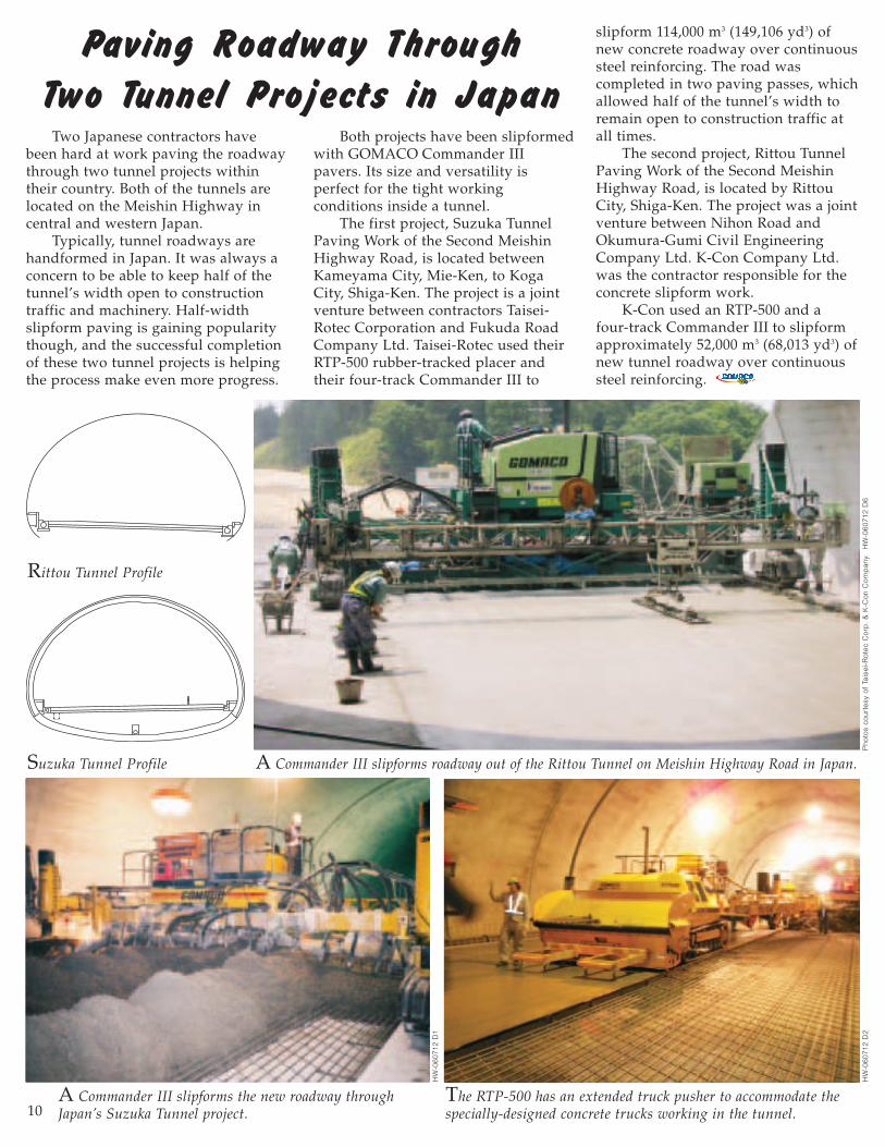
Both projects have been slipformedwith GOMACO Commander IIIpavers. Its size and versatility isperfect for the tight workingconditions inside a tunnel.
The first project, Suzuka TunnelPaving Work of the Second MeishinHighway Road, is located betweenKameyama City, Mie-Ken, to KogaCity, Shiga-Ken. The project is a jointventure between contractors Taisei-Rotec Corporation and Fukuda RoadCompany Ltd. Taisei-Rotec used theirRTP-500 rubber-tracked placer andtheir four-track Commander III to
Paving Roadway Through
Two Tunnel Projects in Japan
slipform 114,000 m3 (149,106 yd3) ofnew concrete roadway over continuoussteel reinforcing. The road wascompleted in two paving passes, whichallowed half of the tunnel’s width toremain open to construction traffic atall times.
The second project, Rittou TunnelPaving Work of the Second MeishinHighway Road, is located by RittouCity, Shiga-Ken. The project was a jointventure between Nihon Road andOkumura-Gumi Civil EngineeringCompany Ltd. K-Con Company Ltd.was the contractor responsible for theconcrete slipform work.
K-Con used an RTP-500 and a four-track Commander III to slipformapproximately 52,000 m3 (68,013 yd3) ofnew tunnel roadway over continuoussteel reinforcing.
A Commander III slipforms roadway out of the Rittou Tunnel on Meishin Highway Road in Japan.
Rittou Tunnel Profile
Suzuka Tunnel Profile
Pho
tos
cour
tesy
of
Tais
ei-R
otec
Cor
p.
& K
-Con
Com
pan
y.
HW
-060
712
D6
HW
-060
712
D1
A Commander III slipforms the new roadway throughJapan’s Suzuka Tunnel project.

11
Betonac slipformed 44,000 m2 (52,625 yd2) of concrete apron at the Charles de Gaulle International Airport in France.
Betonac nv in Sint-Truiden, Belgium, has always beenconcerned about producing quality slipformed concrete. It’sa source of company pride and something they work veryhard at. They’ve implemented the use of several features tohelp maintain quality, including slipforming withGOMACO pavers, operating their own concrete batchplant, and using a paver-mounted GOMACO SmoothnessIndicator® (GSI).
All of these features, combined with a knowledgeablecrew, have given Betonac an edge on their slipformingprojects. They recently left their home country to take ontheir first project abroad at the Charles de GaulleInternational Airport near Roissy, France, 25 km (15.5 mi)northeast of Paris.
They slipformed 44,000 m2
(52,625 yd2) of concrete apron for anew parking lot for FedEx® freightplanes to load and unload. Theywere also responsible forslipforming a transitional concreteslab between the new apron andan existing roadway.
Restrictions for working at theinternational airport, the secondbusiest in terms of both passengertraffic and cargo traffic in Europe,were very tight. Decisions had to
be made about what equipment and what personnel wouldbe working on the site. Applications had to be filled outand turned in before work began and no substitutionsthroughout the course of the project would be allowed.
“Everyone who worked on the job site had to show abadge and we had a limited number of badges at ourdisposal,” Felix Boulez, Betonac’s CEO, explained. “Thechoice of who would apply for one had to be made verycautiously. The same was true for our vehicles. A regulargroup of staff and equipment would work from thebeginning to the end of the job without any possibility ofchange, not even for employee illness or equipmentbreakdowns.”
They knew their four-track GOMACO GHP-2800 paverwas up to the challenge and it wasadded to their equipment list.They also included their four-trackCommander III to pave thetransitional slabs and a GOMACOT/C-600 texture/cure machine.
Their GHP-2800 is equippedwith the Leica stringless guidancesystem, Minnich Auto Vibe IIIsmart vibrator monitoring system,a GOMACO Auto-Float® and apaver-mounted GSI. All arefeatures that help Betonac slipform
Pho
tos
cour
tesy
of
GO
MA
CO
Int
erna
tiona
l Ltd
. H
W-0
2070
3 D
7
34 Paving Passes for a GHP-2800 at the
Charles de Gaulle International Airport

12
the best pavement possible.The new apron is approximately
300 meters (984 ft) long, 170 meters(558 ft) wide and 400 mm (15.7 in)thick. It was slipformed in 34 passeswith the GHP-2800 paving five meters(16.4 ft) wide.
Concrete was supplied byBetonac’s own batch plant capable ofproducing 120 m3 (157 yd3) of concreteper hour. The mix design was astandard paving mix with airentrainment and plasticizer added.Slump averaged 20 mm (0.79 in).
“The design of the concrete isimportant and influences our abilityto get a smooth finish,” Boulez said.“It should be homogeneous during thewhole job so we don’t have to makeany changes to the slipform paver.That is why Betonac prefers toproduce our own concrete.”
Trucks each carrying 12 m3
(15.7 yd3) loads of concretetransported the material to the paver.The trucks dumped into a holdingcontainer and an excavator placed theconcrete in front of the GHP-2800.
Production averaged 100 m3
(131 yd3) per hour or 1200 m3
(1570 yd3) during a 12 hour pavingshift.
“We worked under the capacity ofthe plant, because we wanted to beable to pave continuously,” Boulezexplained. “Paving speed influencessmoothness and is very important. It
has to be tuned to the supply ofconcrete. A speed has to be found thatensures the supply does not get toofar ahead of the paver, but also allowsthe paver to slipform constantly,without starting and stopping.”
The Auto Vibe III system on theirGHP-2800 allows them to constantlymonitor the vibrators’ output. It isanother one of Betonac’s qualitycontrols and the system pinpoints anyvibrator that is not working properly.The system also monitors and controlsall vibrator functions.
Betonac has also left stringlinebehind on all of their major projectsand has been paving exclusively withthe Leica stringless system for overthree years now.
“With the stringless system, weknow that every meter is as theproject should be,” Boulez said. “Withthe 3D system, we need less spacebeside the paver because we don’tneed to allow extra room for thestringline, we have immediate controlbehind the paver, and we have greateraccuracy andprecision.”
The Leica stringlesssystem also has amixed-mode pavingconfiguration. It isespecially helpful onairport projects wherecontractors are pavingpilot lanes. For
example, if a contractor is paving fivelanes total, all adjacent to each other,typically they would pave lane #1, #3,then #5, leaving the gaps for lanes #2and #4 to be filled in later. There hasto be a smooth joint between theconnecting lanes. The 3D mixed-modepaving feature allows the machine tobe steered without having to set upany temporary stringline for the fill-inlanes. They can lock the paver tograde with the track legs to perfectlymatch the grade of the adjacent slabs.
“The mixed-mode paving featureis indispensable,” Boulez said. “Aprimary strip is measured and thisdata is given to our study agency tomake a draft of the adjacent strip.Often it was a strip adjacent to anexisting strip on one side and free onthe other side. In this situation, themixed mode is indispensable toachieve a good result and was veryuseful at the airport.”
Betonac uses three total stations intheir stringless paving process. Two ofthem are constantly tracking and
The GHP-2800 paver-mounted GSI provides Betonac witha constant indication of pavement quality.
The T/C-600 texture/cure machine, equipped with a transversecuring mechanism, tines and cures in a single pass.
HW
-020
703
D16
HW
-020
703
D13

13
HW
-020
703
D15
measuring the prisms on the paver. Athird total station is used to conductas-built checks behind the paver. Thechecks, which are conducted everyfive meters (16.4 ft), measure the lineand level of the new concrete apronand provide instant feedback on theaccuracy of the new slab.
Betonac is always concerned aboutpaving the best project possible andlooking for ways to improve thepaving processes. They have beenusing a paver-mounted GSI on theirGHP-2800 since 2003. It provides themwith a constant indication of theirpavement quality and instantly alertsthem to any potential problems.
“We wanted a GSI to help usobtain maximum quality and to dothat, we have to have a control on thesmoothness during paving,” Boulezexplained. “The GSI, with its bumpalarm, alerts the operator whensomething is wrong. Everything canthen be checked... the vibrators, theLeica system, any external factors thatcan disturb the work, and we can fixthe problem. It gives us the ability toimmediately react when there is anirregularity and gives us a chance to
fix the problem with the Auto-Float orwe can manually touch up the surface.
“We chose the paver-mounted GSI because we first wanted to learnthe system, which went very well,before buying an extra machine. The GHP-2800 also has a stable frame tomount the GSI. Immediately after themold, there is a control and anindication whether something wentwrong and the concrete can bereworked right away.”
The apron specifications includedthree meter (9.8 ft) wide by threemeter (9.8 ft) square recesses that willeventually become fuel pits. Betonachad to create a way to slipform overthe pits, without filling them full ofconcrete. They built a metal formworkthat could be placed in each of thepits. It was filled with sand andcovered with plywood. The GHP-2800could simply pave over the top of thefuel pit, finishers could finish aroundthe structure, and later, when theconcrete had hardened, the formworkwas removed.
The edge of each of the apronpaving passes had an intricate keywaybuilt into it. The sinusoidal (wavy or
curvy) joint was necessary on theairport to help transfer the weight ofthe cargo planes from one section ofapron to the next. The keyway isaccomplished in the slipformingprocess with a special sideplateextension that has the configurationbuilt into it.
Dowel bars were also hand-drilledand inserted every 305 mm (12 in) intothe edge of the longitudinal joint.Longitudinal and transverse joints areevery five meters (16.4 ft).
A GOMACO T/C-600 texture/cure machine followed the paverapplying a transverse tine and awater-based transparent curingcompound. Betonac’s T/C-600 isequipped with a transverse curingmechanism, which allows them tocure and tine simultaneously in asingle pass. In the absence ofstringline, the T/C-600 is sensored offthe slab. The operator manually steerswhile the sensor controls the level ofthe machine.
The transitional slab was paved with Betonac’s four-trackCommander III. The strip was 1200 mm (47.2 in) wide and had avariable thickness. It was 350 mm(13.8 in) thick tying into the concreteapron and tapered down to 150 mm(5.9 in) thick against the existingroadway.
“This was our first project abroadand it was our first airport project of
this size,” Boulez said.“Quality is very important tous and because we have theAuto Vibe III, GSI, stringlesssystem and GOMACOequipment, we havecomplete quality control andeverything under our ownmanagement. We are lookingforward to completing moreprojects like this at homeand abroad.”
Their work is nowcomplete on the parkingapron and Betonac is gearingup for their next project atthe airport. They’ll beslipforming a 145,000 m2
(173,424 yd2) concrete apronfor the Aeroport de Paris’new terminal project.
Betonac’s GOMACO paving train completed 34 paving passes on the airport project. Each pass was300 meters (984 ft) long, five meters (16.4 ft) wide and 400 mm (15.7 in) thick.
“We wanted a GSI to help us obtain maximum qualityand to do that, we have to have a control on thesmoothness during paving,” Boulez explained.

14
The country of Slovakia iscurrently undertaking a massive road-building project to improvetransportation within its borders andto surrounding countries. Slovakia islocated in central Europe and bordersthe Czech Republic, Austria, Poland,Ukraine and Hungary. Part of theeffort to improve transportation iscentered around Motorway D1,running from east to west through the country.
It is currently 259 km (161 mi)long, but new construction in the nextfive years or more will increase it to517 km (321 mi) in length. Doprastav,a.s., based out of Bratislava, Slovakia,is in charge of constructing segmentsof the new motorway, which includesa concrete safety barrier.
The company operates aGOMACO GT-3600 for curb andgutter work on their projects, andwere looking for another GOMACOmachine to slipform the 1100 mm (43.3 in) tall barrier. Once again, theychose the GT-3600, this time
equipping it with a Leica PaveSmart3D system for stringless barrierpaving.
“We have a lot of experience withthe GT-3600 by producing curb andgutter of various dimensions,” JozefVondál, Producing Manager ofDoprastav, said. “We decided to startslipforming barrier wall in May 2006because we saw that it would giveus more production and allow us tobe more effective.”
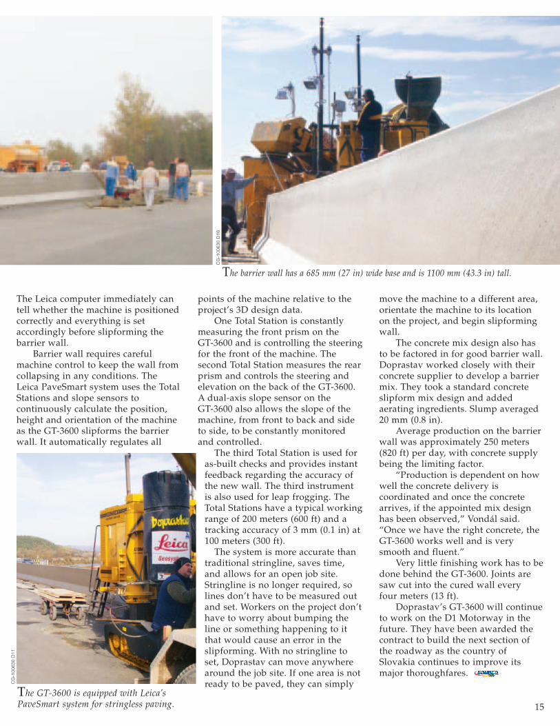
They put their new GT-3600 with stringless system to work on a4 km (2.5 mi) long section of the newmotorway by Zilina, connectingVrtizer to Hricovské Podhradie. Thebarrier wall has a 685 mm (27 in)wide base and is 1100 mm (43.3 in)tall. Four 15 mm (0.6 in) diametersteel cables have to be insertedthrough the front of the barrier moldfor reinforcement in the wall.
Incorporating the stringlessguidance system into their projectrequires just a few steps. Theengineer’s design data for the
project is converted into a surfacemodel. That model is loaded into theLeica computer mounted on the GT-3600. The Leica computer isinterfaced with the GT-3600’s G21controller.
At the start of each day, the GT-3600 is moved into position. Thethree Total Stations used on theproject take measurements offpredetermined reference points toorientate their position. They are thenaimed at the prisms on the GT-3600and they begin the tracking process.
GT-3600 & StringlessBarrier in Slovakia
Doprastav is slipforming a 4 km (2.5 mi) long section of barrier wall on Slovakia’s Motorway D1 without the use of stringlines.
Pho
tos
cour
tesy
of
Kar
l Soa
r C
G-1
0063
0 D
1
Two Total Stations track the GT-3600 as itslipforms barrier wall through a radius.
CG
-100
630
D11
15
The Leica computer immediately cantell whether the machine is positionedcorrectly and everything is setaccordingly before slipforming thebarrier wall.
Barrier wall requires carefulmachine control to keep the wall fromcollapsing in any conditions. TheLeica PaveSmart system uses the TotalStations and slope sensors tocontinuously calculate the position,height and orientation of the machineas the GT-3600 slipforms the barrierwall. It automatically regulates all
points of the machine relative to theproject’s 3D design data.
One Total Station is constantlymeasuring the front prism on the GT-3600 and is controlling the steeringfor the front of the machine. Thesecond Total Station measures the rearprism and controls the steering andelevation on the back of the GT-3600.A dual-axis slope sensor on the GT-3600 also allows the slope of themachine, from front to back and sideto side, to be constantly monitoredand controlled.
The third Total Station is used foras-built checks and provides instantfeedback regarding the accuracy ofthe new wall. The third instrumentis also used for leap frogging. TheTotal Stations have a typical workingrange of 200 meters (600 ft) and atracking accuracy of 3 mm (0.1 in) at100 meters (300 ft).
The system is more accurate thantraditional stringline, saves time,and allows for an open job site.Stringline is no longer required, solines don’t have to be measured outand set. Workers on the project don’thave to worry about bumping theline or something happening to itthat would cause an error in theslipforming. With no stringline toset, Doprastav can move anywherearound the job site. If one area is notready to be paved, they can simply
move the machine to a different area,orientate the machine to its locationon the project, and begin slipformingwall.
The concrete mix design also hasto be factored in for good barrier wall.Doprastav worked closely with theirconcrete supplier to develop a barriermix. They took a standard concreteslipform mix design and addedaerating ingredients. Slump averaged20 mm (0.8 in).
Average production on the barrierwall was approximately 250 meters(820 ft) per day, with concrete supplybeing the limiting factor.
“Production is dependent on howwell the concrete delivery iscoordinated and once the concretearrives, if the appointed mix designhas been observed,” Vondál said.“Once we have the right concrete, theGT-3600 works well and is verysmooth and fluent.”
Very little finishing work has to bedone behind the GT-3600. Joints aresaw cut into the cured wall every four meters (13 ft).
Doprastav’s GT-3600 will continueto work on the D1 Motorway in thefuture. They have been awarded thecontract to build the next section ofthe roadway as the country ofSlovakia continues to improve itsmajor thoroughfares.
The barrier wall has a 685 mm (27 in) wide base and is 1100 mm (43.3 in) tall.
CG
-100
630
D16
The GT-3600 is equipped with Leica’sPaveSmart system for stringless paving.
CG
-100
630
D11

The All-American Canalin southern Californiadelivers approximately 3.1 million acre-feet (382,379 ha m) of theColorado River to nine cities and 500,000 acres(202,343 ha) of agriculturalland. The 82 mile (132 km)long canal was originallyconstructed in the 1930s and1940s. It begins at theImperial Dam on the
Colorado River, about 20 miles (32 km) northeast of Yuma,Arizona, and extends south and west, following the Mexican/American border.
The canal is currently unlined and substantial amounts ofwater are lost due to seepage, according to the ImperialIrrigation District, who operate and maintain the All-AmericanCanal. They want to rebuild a section of the canal, with thenew canal constructed parallel to the existing canal. The newconcrete-lined canal will help minimize water lost because ofseepage. Coffman Specialties, based out of San Diego,California, won the initial project bid to complete a portion ofthe new canal.
The All-American Canal PaverNot Your Ordinary Paver – A quick look at any preliminary drawingof the All-American Canal paver will show you that this paveris not your ordinary canal paver. This canal will be a trueslipform project. GOMACO built a canal slipform paver in the
All-A
mer
ican
Can
al P
roject
It’s Not YourOrdinary Canal
Paver...Coffman Specialties needed canal paving
equipment, three very specific and unique
machines, for the All-American
Canal project. They turned to
GOMACO as their
manufacturer of choice to
build an all new
canal slipform
paver, water
stop machine
and work bridge.
The paver and work bridge for the All-American Canal sits on the pier at GOMACO’s testing facilities in Ida Grove, Iowa.
16
EG
-110
601
D10
EG
-100
618
D19

late 1980s for the Coachella Canalproject in southern California(GOMACO World, Vol. 17, No. 2).Coachella’s new concrete lining wasslipformed underwater withapproximately nine feet (2.7 m) ofwater flowing in the canal. Much of theinformation learned on the Coachellaproject was incorporated into the All-American equipment.
A GOMACO GP-4000 prime moverwill be set on top of a Coachella-styleframework to provide the power plantand control system for the paver. Theframework itself will be ten feet (3 m)tall. The mold sections are a 5000 seriespaving mold that has been modifiedslightly. The machine is mounted onfour tracks... four very large tracks thatare 13 feet, nine inches (4.2 m) long, 30 inches (762 mm) wide and 40 inches(1016 mm) high.
Supplying the Concrete – Placing concretedown the 40 foot (12.2 m) long, 1.75:1or 2:1 slope and 25 foot (7.6 m) widecanal floor is a serious challenge. One
The All-American Canal paver features framework that is 10 feet (3 m) tall with a GP-4000 prime mover. It also has a powered wedgethat allows the paver to be adjusted to the different angles caused by the changing widths and slopes of the canal.
On the testing pier– the pier simulates the slope of the canal and allows engineers to testthe different features on all three pieces of canal equipment.
EG
-100
631
D8
EG
-110
602
D7
17

fracture joints.“It creates a 15 foot (4.6 m) section
for the concrete to fracture to allow forsoil movement and other conditions,”Jim Homan, GOMACO’s projectmanager for the All-American Canalequipment, said. “Once the fracturetakes place, the water stop is boundinto the concrete slab and allows it tomove and flex. It’s also creating a sealthat keeps water from leaking throughthe canal into the soil below.”
The Water Stop MachineThe Transverse Water Stop – The secondpiece of equipment GOMACO hasbuilt for the All-American Canalpaving train is the water stop machine.It follows directly behind the canalpaver inserting the transverse waterstop material every 15 feet (4.6 m). Theproduction rate on the project is alldependent on this one machine andthat created an extra challenge in thedesign process.
The inserter is made of eight footby eight foot (2.4 x 2.4 m) framesections, with the outside dimensionsthe same as the paver. It features afixed and hydraulically-adjustable endcar and powered wedge similar to thepaver to match the canal profile.
The inserter is powered by an
80 horsepower (59.7 kw) engine andrun on Series 6 tracks that are 16 feet(4.9 m) long with 20 inch (508 mm)polypads.
Inserting the Water Stop – The rubberwater stop material will be insertedinto the wet concrete by a specially-designed inserter mechanism that willride on a carriage mounted to theframe. A large spool of the water stopmaterial will also be attached to theframework. As the carriage movesdown the canal wall, it will pull thewater stop material off the spool anddown the slope. At the bottom of thecanal, a worker will anchor thematerial to the canal floor. Thecarriage, with the inserter mechanism,will then move up the canal wallopening up a trough approximately1.75 inches (44 mm) wide by one inch(25 mm) deep and place the water stopmaterial in the trough.
The top of the rubber water stopmaterial is placed one-eighth of aninch (3 mm) below the surface to allowfor controlled cracking in the canal.The process is repeated every 15 feet(4.6 m) along the length of the canal.
A 17 foot (5.2 m) long cylinder andfloat pan follows the inserter. Thecylinder helps finish and seal the
of the unique aspects of the paver is itsconcrete distribution system mountedto the front. Concrete trucks will dumpinto a standard GOMACO RTP-500rubber-tracked placer which will thenplace the concrete into the distributionsystem on the paver.
The distribution system is basicallya paddle system with baffles that runalong the slope of the canal. Thepaddles move the concrete down theslope and the baffles collect theconcrete to keep all of it from slidingdown to the bottom of the slope.Vibrators are mounted transversely,rather than perpendicular to the mold.A spreader-plow, on the bottom 25 foot(7.6 m) wide section of the canal floor,will move the concrete across thatwidth.
The canal’s new lining will be fourinches (102 mm) thick and will beslipformed in two paving passes.
Changing Widths and Slopes – The design ofthe canal itself presented an interestingchallenge for GOMACO engineerswhile designing the paver. The slope ofthe canal is not constant and the lengthof the slope is variable. The paver hasto be able to accommodate the changesas quickly and easily as possible.
Two different types of end cars aremounted to the framework of thepaver - a fixed end car and anadjustable end car. The adjustable endcar can be hydraulically slid in or outwhile the paver is stopped toaccommodate the different slopes. Itallows the length changes to be madewithout having to add or remove anysections of framework.
The other crucial feature is thepowered wedge. When the length ofthe slope changes, it also changes theangle of slope on the canal and thepivot point on the paver. The poweredwedge makes the machine adjustableto the canal’s different angles.
Fracture Joints – The specifications on thecanal require a longitudinal andtransverse fracture joint every 15 feet(4.6 m). Four massive spools of cross-shaped, polyvinyl chloride rubberstrips will be mounted to the paver.The material will be inserted by aspecially designed insertingmechanism into the four inch (102 mm)thick concrete on the go, during theslipforming process. The longitudinalwater stops will then create the canal’s
The spreader-plow moves the concreteacross the bottom section of the canal floor.
A paddle system with baffles places theconcrete down the slope of the canal.
Adjustable end cars on the machineshydraulically slide for width changes.
Modified 5000 series paving molds wait to beattached to the canal paver during assembly.
EG
-100
606
D6
EG
-100
631
D30
EG
-110
601
D16
EG
-100
606
D10
18

surface of the canal. The water stop machine has to be
able to keep up with the paver so theconcrete doesn’t cure and become toohard to insert the material. That’s onechallenge. Another challenge is projectspecifications.
“This machine has to be able toinsert a joint every three minutes to beable to pave five feet (1.5 m) perminute,” Steve Johnson, GOMACOProject Designer, said. “If they cankeep concrete in front of the paver forthat kind of production, this machineis certainly capable of keeping up.”
Extensive research and testingtook place to create the insertiondevice. Not only does it have to placethe material on-the-go in the pavingprocess, but place it at the requireddepth, standing in the uprightposition, and with the concreteconsolidated around the material.
“The concept itself is relativelyeasy,” Homan explained. “But in theenvironment the inserter has to workin, the complications of going througha radius, and other aspects make thisan interesting challenge and this avery important machine in the canal
paving process.”
The Canal’s Work BridgeThe Work Bridge’s Unique Design – Like allthe machines for this project, the workbridge is a unique design with severaldifferent aspects to it. It mirrors thepaver and water stop inserter inseveral features to match the changingdimensions of the canal, including afixed and hydraulically-adjustable endcar and powered wedge.
The console on the canal’s workbridge will be similar to the one usedon the water stop inserter. Thecontinuation of the same componentson the different canal machines helpsout in the field with operation andmaintenance.
The framework itself is four feet(1.2 m) wide by seven feet (2.1 m) tall,with the console located at the bottomof the machine. It will run on SeriesOne tracks equipped with 17.7 inch(450 mm) rubber track pads. Duringthe second paving pass, the machineswill be running on the concrete fromthe first pass. The extra large trackpads will keep the work bridge fromcracking or marring the surface of thenew canal.
An Auto-Float® will be mounted tothe back of the work bridge and willfinish while working up the slope. Itwill lift off the concrete, cycle backdown to the bottom of the canal andcomplete another pass.
Testing the EquipmentNew Canal Assembly and Testing Site – Thefinal phase of the equipment’s designand manufacturing was full machineassembly. GOMACO has constructed anew canal assembly and testing site attheir company headquarters in IdaGrove, Iowa. The site includes a newconcrete pier that is 16 feet (4.9 m) tall,60 feet (18.3 m) long, and 72 inches(1829 mm) wide. It can accommodatealmost any size canal paver, as the All-American Canal equipment hasproven.
Each piece of the equipment wasfully assembled and then placed onthe pier so engineers could test itsvarious features and performancecapabilities. The canal equipment waslater disassembled and shipped. Over20 truckloads were needed totransport all of the canal pavingequipment to California.
The water stop inserter machine has a specially designed inserter mechanism to place therubber water stop material into the concrete every 15 feet (4.6 m) to form the transverse joint.
The powered wedge system allows the machinesto go from flat to varying degrees of slope.
A 17 foot (5.2 m) long finishing cylinderwith float pan will finish and seal thesurface of the canal.
EG
-040
707
D3
EG
-040
707
D10
EG
-040
707
D15

New GOMACO Technology Introduced at
The Commander III four-track on the Bauma stand.
Kent Godbersen (from left), GOMACO’s Vice-President of Worldwide Sales & Marketing, andRory Keogh, GOMACO International Ltd.Managing Director, discuss equipment needs withrepresentatives from Turkey.
A delegation of contractors from Cámara Chilenade la Construcción A.G. of Chile were guests in theGOMACO booth at Bauma 2007.
Representatives from Apolodor visited theGOMACO stand to see their new GT-3600 ondisplay. Their GT-3600 will be the first GOMACOslipform machine to operate in Romania.
Vinayak Rege (left), GOMACO’sService Representative in India,explains canal paving to apotential customer from Pakistan.
Representatives from B.R. Goyal met with AndyLinham (second from right), GOMACO AreaManager for India. Goyal recently purchased thefirst two-track GP-2600 sold in India.
A view down the main aisle of GOMACO’sstand at Bauma in Munich, Germany.
Kent Godbersen, GOMACO,(left) and Michelle LeCompte ofLeCompte stand in front of thecompany’s new GT-3400 ondisplay in the stand.
From left, RJ Bumann,GOMACO Controls SoftwareEngineer, and John Bowden,GOMACO International Ltd.Technical Sales Manager,discuss the new G22 controlsystem with contractors fromPoland.
CV-
0407
10 D
28C
V-04
0713
D26
CV-
0407
14 D
18C
V-04
0712
D14
CV-
0407
13 D
1C
V-04
0711
D19
CV-
0407
13 D
29
CV-
0407
14 D
4
CV-
0407
14 D
26
Contractors and guests from around the world visited the GOMACO stand atBauma 2007 to see the newest machine innovations.
CV-
0407
12 D
4

21
Bauma 2007 was an exciting showfor GOMACO. We introduced thenew GT-3400 internationally with twoof the new machines in our stand toshowcase its right-side and left-sidecurb and gutter slipformingcapabilities. The right-side pour GT-3400 also featured the latest inLeica’s stringless curb and guttertechnology, the PaveSmart 3D system.The system incorporates both TotalStations and a GPS unit for grade andsteering accuracy on GOMACO curband gutter machines.
Both of the GT-3400s and theCommander III featured the powerfulnew G22 digital controller, with dual-language option. The option isavailable in both English and thecustomer’s language of choice.GOMACO’s control systems team candevelop the G22 for all the majorlanguages of the world. The G22 alsohas an easy to understand graphicaldisplay with colored pictogramsdepicting the machine’s functions.Fourteen function buttons withbright, colored graphics provide theultimate user-friendly operatorexperience.
A GT-3600 in the GOMACO standfeatured Topcon’s new stringlessMillimeter GPS™ control system.Topcon’s system incorporates GPStechnology to guide GOMACOequipment without the use ofstringline. The GT-3600 was set upwith a step barrier mold, a profile ofwall that is quickly becoming thestandard profile in Europe.
“It appears this is the best Baumashow ever for GOMACO,” GaryGodbersen, GOMACO President andCEO, said. “We enjoyed talking withcontractors from around the world,discussing their upcoming projectsand helping them find the solutionsfor their slipform paving needs.”
As a show, Bauma 2007 was arecord-setting event. A total of 200,000tons of freight was moved in by 6000trucks for the Munich, Germany,show. More than 500,000 visitorswalked the show grounds and visitedthe stands of the 3041 exhibitorsduring the week-long show. Onehundred and ninety countries wererepresented at Bauma 2007.
Bauma ‘07 Commander III: The Contractor’s Choicefor both Concrete Pavers and Curb and Gutter Machines
The GOMACO Commander III has beennamed the “2007 Contractor Choice” by Roadsand Bridges magazine. The Commander IIIearned the magazine’s gold award distinctionfor both concrete pavers and concrete curb and gutter, making both the three-track andfour-track machine the choice of concretecontractors.
Roads and Bridges had asked manufacturersand service providers to nominate products tobe eligible for the second annual Contractor’sChoice awards. An expert panel of judgesreviewed all the nominations and a ballot was formed and delivered to more than
22,000 contractors subscribing to the magazine. Contractors in this segmentwere eligible to vote for the best equipment on the job site and their choice wasthe Commander III.
GOMACO was also named the #1 Brand Leader for the categories of curband gutter machines and slipform pavers by Concrete Construction magazine.Contractors who participated in the survey ranked the GOMACO name first inbrand familiarity, and first in the brand used in the past two years. Themagazine, whose publisher sponsors the World of Concrete show each year,surveyed contractors from their circulation. The sampling was divided intofour regions of the United States: Northeast, Midwest, South and West, to getthe fairest representation.
Better Roads magazine also recognized not one, but two GOMACO productsin their Top 50 Rollouts. The variable width V2 mold and GSITools™ softwareapplication for use with the GOMACO Smoothness Indicator® (GSI) eachearned the top honor. Each year, Better Roads magazine reviews all productintroductions made over the past year, and picks out the 50 with the mostsignificance to highway and bridge professionals. Priorities for inclusion arenew concept products and new generation products.
GOMACO has been recognized as a “Patriotic Employer” by the NationalCommittee for Employer Support of the Guard and Reserve. The award is forcontributing to national security and protecting liberty and freedom bysupporting employee participation in America’s National Guard and Reserveforce. The program recognizes employers whose support and good will areimportant to retaining highly skilled and qualified members of the Guard andReserve.
Book Your Trip to CONEXPO-CON/AGG 2008Today to Guarantee Rooms and Airfare!CONEXPO-CON/AGG 2008 will be March 11-15, 2008, in Las Vegas,
Nevada. If you plan on attending, you need to be reserving your plane ticketsand hotel rooms now. There are a number of other shows and sporting eventsall happening in Las Vegas at the same time, making rooms and flights in andout of the city a premium item.
You can register for the show and even make your domestic orinternational travel plans, car rental and hotel reservations right from theshow’s site, just visit http://www.conexpoconagg.com/Attendee/overviewand the website will help walk you through the process.
GOMACO will be in Booth #C-5657 in the Central Hall of the Las VegasConvention Center. We can’t wait to see you there to discuss your concretepaving needs for 2008!

CG
-100
617
D28
South East Concreting Pty. Ltd. slipformshalf-width roadway with their four-trackCommander III on a new roadway inSydney, Australia.
The joint venture team of CDS and Mukand are using a four-track GHP-2800 withIDBI to slipform the new National Highway 2 between the cities of Kanpur andAllahabad in Uttar Pradesh, India.
Kodama slipforms 3.5 meter (11.5 ft) widepavement with their Commander III three-track on a project in Santiago, Chile.
Abi Group Limited slipforms barrier wall with their four-track Commander III on theM7 Motorway near Sydney, New South Wales, Australia.
CG
-050
715
D19
HW
-040
708
D3
CEMEX slipforms a new roadway south of Cancun, Mexico, with their new GP-4000 withIDBI. A GSI® follows behind the paver measuring the smoothness of the new roadway.
HW
-100
602
D20
CV-
0507
01 D
2
Leis Maquinarias, GOMACO’s distributorin Chile, promoted our equipment at theExpo Hormigon ICH show in May inSantiago, Chile.
CG
-100
509
D20
a r o u n d t h e w o r l d
HW
-020
704
D20
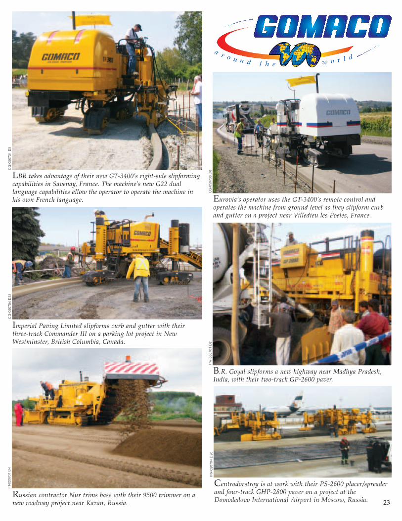
Centrodorstroy is at work with their PS-2600 placer/spreaderand four-track GHP-2800 paver on a project at theDomodedovo International Airport in Moscow, Russia.
Russian contractor Nur trims base with their 9500 trimmer on anew roadway project near Kazan, Russia.
FT-0
2070
1 D
4
Imperial Paving Limited slipforms curb and gutter with theirthree-track Commander III on a parking lot project in NewWestminster, British Columbia, Canada.
CG
-050
704
D22
HW
-060
701
D2
B.R. Goyal slipforms a new highway near Madhya Pradesh,India, with their two-track GP-2600 paver.
CG
-050
731
D8
CG
-050
730
D8
Eurovia’s operator uses the GT-3400’s remote control andoperates the machine from ground level as they slipform curband gutter on a project near Villedieu les Poeles, France.
23
LBR takes advantage of their new GT-3400’s right-side slipformingcapabilities in Savenay, France. The machine’s new G22 duallanguage capabilities allow the operator to operate the machine inhis own French language.
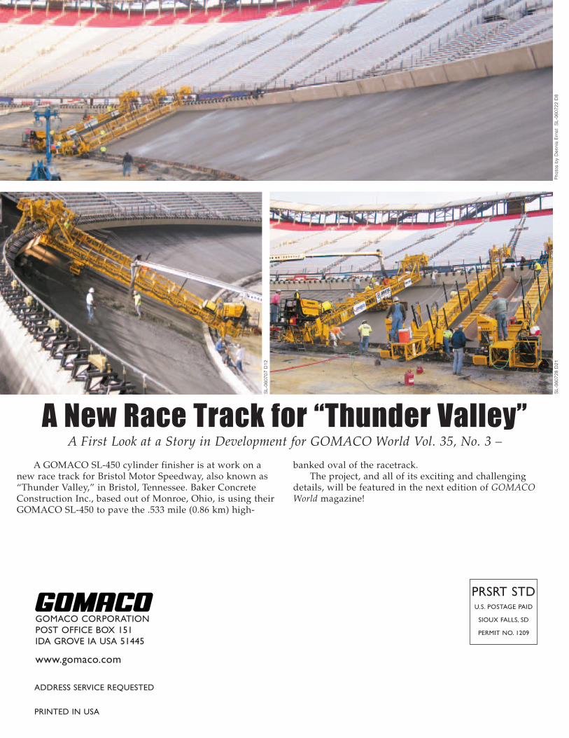
A GOMACO SL-450 cylinder finisher is at work on anew race track for Bristol Motor Speedway, also known as“Thunder Valley,” in Bristol, Tennessee. Baker ConcreteConstruction Inc., based out of Monroe, Ohio, is using theirGOMACO SL-450 to pave the .533 mile (0.86 km) high-
banked oval of the racetrack. The project, and all of its exciting and challenging
details, will be featured in the next edition of GOMACOWorld magazine!
PRSRT STDU.S. POSTAGE PAID
SIOUX FALLS, SD
PERMIT NO. 1209
ADDRESS SERVICE REQUESTED
PRINTED IN USA
GOMACO CORPORATIONPOST OFFICE BOX 151IDA GROVE IA USA 51445
www.gomaco.com
A New Race Track for “Thunder Valley”A First Look at a Story in Development for GOMACO World Vol. 35, No. 3 –
Pho
tos
by
Den
nis
Ern
st
SL-
0607
22 D
8S
L-06
0728
D21
SL-
0607
07 D
12