special purpose nuclear reactor (5 mw) for reliable … · m. g. mckellar . a. j. hummel . j. c....
TRANSCRIPT

The INL is a U.S. Department of Energy National Laboratory operated by Battelle Energy Alliance
INL/EXT-16-40741 Revision 1
Special Purpose Nuclear Reactor (5 MW) for Reliable Power at Remote Sites Assessment Report Using Phenomena Identification and Ranking Tables (PIRTs)
J. W. Sterbentz J. E. Werner
M. G. McKellar A. J. Hummel J. C. Kennedy R. N. Wright
J. M. Biersdorf
April 2017

DISCLAIMER
This information was prepared as an account of work sponsored by an agency of the U.S. Government. Neither the U.S. government nor any agency thereof, nor any of their employees, makes any warranty, expressed or implied, or assumes any legal liability or responsibility for the accuracy, completeness, or usefulness, of any information, apparatus, product, or process disclosed, or represents that its use would not infringe privately owned rights. References herein to any specific commercial product, process, or service by trade name, trade mark, manufacturer, or otherwise, does not necessarily constitute or imply its endorsement, recommendation, or favoring by the U.S. Government or any agency thereof. The views and opinions of authors expressed herein do not necessarily state or reflect those of the U.S. government or any agency thereof.

INL/EXT-16-40741 Revision 1
Special Purpose Nuclear Reactor (5 MW) for Reliable Power at Remote Sites Assessment Report
J. W. Sterbentz J. E. Werner
M. G. McKellar A. J. Hummel J. C. Kennedy R. N. Wright
J. M. Biersdorf
April 2017
Idaho National Laboratory Nuclear Science and Technology Division
Idaho Falls, Idaho 83415
http://www.inl.gov
Prepared for the U.S. Department of Energy Office of Nuclear Energy
Under DOE Idaho Operations Office Contract DE-AC07-05ID14517


iii
ABSTRACT
The Phenomena Identification and Ranking Table (PIRT) technique was conducted on the Special Purpose Reactor nuclear plant design. The PIRT is a structured process to identify safety-relevant/safety-significant phenomena and assess the importance and knowledge base by ranking the phenomena. The Special Purpose Reactor is currently in the conceptual design phase. The candidate reactor has a solid monolithic stainless steel core with an array of heat pipes and fuel pellets embedded in the monolith. The heat pipes are used to remove heat from the core using simple, reliable, and well-characterized physics (capillarity, boiling, and condensation). In the initial design, one heat exchanger is used for the working fluid that produces energy, and a second heat exchanger is used to remove decay heat in emergency or shutdown conditions. In addition, a power conversion cycle such as an open-air Brayton system is available as an option for power conversion and process heat.
This report summarizes and documents the process and scope of the four PIRT reviews, noting the major activities and conclusions. The identified phenomena, analyses, rationales, and associated ratings are presented along with a summary of the findings from the four individual PIRTs, namely (1) Reactor Accident and Normal Operations, (2) Heat Pipes, (3) Materials, and (4) Power Conversion. The PIRT reports for these four major system areas evaluated are attached as appendixes to this report and provide considerably more detail about each assessment as well as a more complete listing of the phenomena that were evaluated.

iv

v
EXECUTIVE SUMMARY The Special Purpose Reactor, also known as the “MegaPower” reactor by the Los Alamos National
Laboratory (LANL) designers, is a 5 MW thermal, fast reactor design concept. Reactor system characteristics include a relatively small footprint, passively safe operation, and a self-contained geometry, providing a plug-and-go power source for remote installations and communities. This concept uniquely features an array of in-core heat pipes for passive heat transfer, thus avoiding traditional primary circuit equipment and eliminating severe accident scenarios of loss-of-forced-cooling. Plus, the large number of in-core heat pipes provides built-in redundancy in the event of a single heat pipe failure.
The LANL design is highly evolved, especially in the areas of neutronics and thermal-hydraulics. The reactor design exhibits many positive characteristics typical of a well-designed reactor core. These include strong negative reactivity feedbacks, low power density, long-life, ample control-drum worth, independent emergency control rod shutdown systems, and passive heat removal. Reactor kinetic response for this very small reactor should be straightforward, predictable, and easy to control.
The Phenomena Identification and Ranking Tables (PIRT) technique is a structured process to help identify safety-relevant and safety-significant phenomena and assess the importance of such phenomena to the design. The four PIRT topical areas are:
1. Reactor Accident and Normal Operation Conditions;
2. Heat Pipes;
3. Materials; and
4. Power Conversion.
The most significant findings from the four PIRTs are those phenomena ranked with a “high” importance and a corresponding “low” or “medium” knowledge level. These most significant phenomena will impede deployment of a first-of-a-kind (FOAK) reactor system, because either additional research and development or significant system redesign will be required.
The PIRT analysis on the Special Purpose Reactor has confirmed many of the above mentioned positive attributes, but it has also uncovered several concerns that will challenge system constructability, operability, and licensing, despite the use of basic reactor materials with high technology readiness levels. Many of these concerns relate to the engineering aspects of the design, such as system component fabrication, assembly, inspection, and repair. Perhaps a more important concern is an adequate approach to defense-in-depth through barriers to prevent and mitigate radioactive releases during failure events and thermal stress levels exceeding ASME pressure vessel code limits. The double containment incorporated into the design satisfies the single failure criterion, but is not sufficient for defense in depth. Many of these design concerns can, however, potentially be overcome by implementing the research and development recommendations identified by the PIRT and listed in this report.
The PIRT has also identified several phenomena ranked with a “low” knowledge level. Some of these phenomena and their impact to the reactor system are actually “unknown” due to either a lack of detailed analysis, which is partly due to the limited nature of a PIRT process, or a lack of supporting experimental data. Some of these unknowns are also major concerns. Examples include seismic event impacts, heat pipe performance under long-term irradiation exposure, understanding of heat pipe failure modes, and design and implementation of the shell and tube primary heat exchanger. Understanding these “unknowns” better will help reduce the expectation that each by itself could trigger a system failure, leading to a permanent reactor shutdown.
The reactor core reactivity is very sensitive to virtually any in-core dimensional change. For example, increasing the minimum web thickness in the steel monolith from 1 mm to 2 mm causes the reactor to go sub-critical. Similar sensitivities exist if the design were to incorporate a dedicated fuel clad or an in-core

vi
heat pipe wall. Incorporation of a fuel clad and an in-core heat pipe wall would add robustness to the system and defense-in-depth under accident conditions. The current system could accommodate these two important modifications, but would require an increase in core size and weight. Without these two changes, design certification will be very difficult.
INL has evaluated the LANL design through the PIRT process and has identified several areas of concern. These concerns will need to be addressed through additional definition and re-design of the concept, plus additional research and development to boost component technology readiness levels. Based on the PIRT assessment, it is unlikely that the current LANL design would be able to meet an aggressive 7-year deployment schedule for a first-of-a-kind (FOAK) prototype. Major concerns revolve around the low technology readiness level of the monolith. It is recommended that selected design studies, including exploring alternate designs to the monolith and power conversion, be undertaken to meet 7-year delivery schedule.

vii
CONTENTS
ABSTRACT ................................................................................................................................................. iii
EXECUTIVE SUMMARY .......................................................................................................................... v
ACRONYMS ............................................................................................................................................... xi
1. INTRODUCTION ............................................................................................................................ 13 1.1 Background ............................................................................................................................ 13 1.2 The Phenomena Identification and Ranking Table (PIRT) .................................................... 14 1.3 Report Organization ............................................................................................................... 14
2. SPECIAL PURPOSE REACTOR: PLANT BASIC TECHNOLOGY DESCRIPTION ................. 14
3. OBJECTIVES................................................................................................................................... 18 3.1 INL PIRT Team ..................................................................................................................... 18 3.2 PIRT Process Description ...................................................................................................... 18 3.3 Accident and Normal Scenario Selection .............................................................................. 20
4. PIRT ANALYSES ............................................................................................................................ 22 4.1 Phenomena Identification and Description ............................................................................ 22 4.2 Ranking Rationale .................................................................................................................. 22 4.3 Accident Analysis .................................................................................................................. 22 4.4 Team Analysis ........................................................................................................................ 22
5. ASSESSMENT OF THE LANL SPECIAL PURPOSE REACTOR DESIGN ............................... 24
Appendix A Reactor Accident and Normal Operations PIRT ................................................................. A-1
Appendix B Heat Pipe PIRT .................................................................................................................... B-1
Appendix C Materials PIRT .................................................................................................................... C-1
Appendix D Power Conversion Unit and HXs ........................................................................................ D-1
Appendix E Thermal and Structural Analysis ......................................................................................... E-1
Appendix F Neutronic Analysis ................................................................................................................ F-1
Appendix G Special Purpose Reactor Plant Assessment Report ............................................................. G-1

viii
FIGURES Figure 1. Special Purpose Reactor concept schematic. ............................................................................... 13
Figure E-1. Cross-sectional view of the LANL Special Purpose Reactor core. ..................................... E-10
Figure E-2. Abaqus model geometry of a single 60° reactor core sector. .............................................. E-11
Figure E-3. Axial cross-section view of a 60° reactor core sector. ......................................................... E-12
Figure E-4. Heat pipe and fuel pin numbering scheme. .......................................................................... E-13
Figure E-5. Transverse cross-section of nominal condition monolith and fuel mid-plane temperatures (units in K). ....................................................................................................... E-15
Figure E-6. Axial cross-section of nominal condition monolith and fuel centerline temperatures E- (units in K). ........................................................................................................................ E-16
Figure E-7. Transverse cross-section of nominal condition monolith mid-plane temperatures (units in K). ............................................................................................................................. E-17
Figure E-8. Transverse cross-section of nominal condition monolith mid-plane heat flux (units in W/m2). ..................................................................................................................................... E-18
Figure E-9. Transverse cross-section of nominal condition monolith mid-plane Mises stresses (units in Pa). ............................................................................................................................ E-19
Figure E-10. Transverse cross-section of nominal condition monolith mid-plane strain (units in strain). ..................................................................................................................................... E-20
Figure E-11. Radial thermal expansion under nominal conditions (units in m). .................................... E-21
Figure E-12. Axial thermal expansion under nominal conditions (units in m). ...................................... E-22
Figure E-13. Total thermal expansion under nominal conditions (units in m). ...................................... E-23
Figure E-14. Transverse cross-section of 1 failed heat pipe condition monolith and fuel mid-plane temperatures (units in K). ....................................................................................................... E-25
Figure E-15. Axial cross-section of 1 failed heat pipe condition monolith and fuel centerline temperatures (units in K). ....................................................................................................... E-26
Figure E-16. Transverse cross-section of 1 failed heat pipe condition monolith mid-plane temperatures (units in K). ....................................................................................................... E-27
Figure E-17. Transverse cross-section of 1 failed heat pipe condition monolith mid-plane heat flux (units in W/m2). ............................................................................................................... E-28
Figure E-18. Transverse cross-section of 1 failed heat pipe condition monolith mid-plane Mises stresses (units in Pa). .............................................................................................................. E-29
Figure E-19. Transverse cross-section of 1 failed heat pipe condition monolith mid-plane strain (units in strain). ....................................................................................................................... E-30
Figure E-20. Radial thermal expansion under 1 failed heat pipe conditions (units in m). ...................... E-31
Figure E-21. Axial thermal expansion under 1 failed heat pipe conditions (units in m). ....................... E-32
Figure E-22. Total thermal expansion under 1 failed heat pipe conditions (units in m). ........................ E-33
Figure E-23. Transverse cross-section of 2 failed heat pipe condition monolith and fuel mid-plane temperatures (units in K). ....................................................................................................... E-34

ix
Figure E-24. Axial cross-section of 2 failed heat pipe condition monolith and fuel centerline temperatures (units in K). ....................................................................................................... E-35
Figure E-25. Transverse cross-section of 2 failed heat pipe condition monolith mid-plane temperatures (units in K). ....................................................................................................... E-36
Figure E-26. Transverse cross-section of 2 failed heat pipe condition monolith mid-plane heat flux (units in W/m2). ............................................................................................................... E-37
Figure E-27. Transverse cross-section of 2 failed heat pipe condition monolith mid-plane Mises stresses (units in Pa). .............................................................................................................. E-38
Figure E-28. Transverse cross-section of 2 failed heat pipe condition monolith mid-plane strain (units in strain). ....................................................................................................................... E-39
Figure E-29. Radial thermal expansion under 2 failed heat pipe conditions (units in m). .......................... 40
Figure E-30. Axial thermal expansion under 2 failed heat pipe conditions (units in m). ........................... 41
Figure E-31. Total thermal expansion under 2 failed heat pipe conditions (units in m). ............................ 42
Figure E-32. Transverse cross-section of 3 failed heat pipe condition monolith and fuel mid-plane temperatures (units in K). ....................................................................................................... E-43
Figure E-33. Axial cross-section of 3 failed heat pipe condition monolith and fuel centerline temperatures (units in K). ....................................................................................................... E-44
Figure E-34. Transverse cross-section of 3 failed heat pipe condition monolith mid-plane temperatures (units in K). ....................................................................................................... E-45
Figure E-35. Transverse cross-section of 3 failed heat pipe condition monolith mid-plane heat flux (units in W/m2). ............................................................................................................... E-46
Figure E-36. Transverse cross-section of 3 failed heat pipe condition monolith mid-plane Mises stresses (units in Pa). .............................................................................................................. E-47
Figure E-37. Transverse cross-section of 3 failed heat pipe condition monolith mid-plane strain (units in strain). ....................................................................................................................... E-48
Figure E-38. Radial thermal expansion under 3 failed heat pipe conditions (units in m). ...................... E-49
Figure E-39. Axial thermal expansion under 3 failed heat pipe conditions (units in m). ....................... E-50
Figure E-40. Total thermal expansion under 3 failed heat pipe conditions (units in m). ........................ E-51
Figure F-1. MCNP model of special purpose reactor with optional SS vessel (green) and outer B4C shield. ................................................................................................................................ F-4
Figure F-2. MCNP lattice of heat pipes (yellow) surrounded by fuel pins (red). ..................................... F-4
Figure F-3. Fuel temperature coefficient of reactivity. ............................................................................. F-6
Figure F-4. Fuel thermal expansion coefficient of reactivity. ................................................................... F-6
Figure G-1. Simple air Brayton power cycle. ........................................................................................... G-3
Figure G-2. Air Brayton cycle with compressor intercooling, heat recuperation and reheat.................... G-4
Figure G-3. Recuperated air Brayton cycle for the Special Purpose Reactor. .......................................... G-5
Figure G-4. Aspen HYSYS model of simple air Brayton cycle. .............................................................. G-6
Figure G-5. Aspen HYSYS model of heat recuperated air Brayton cycle. ............................................... G-7

x
Figure G-6. Power and thermal efficiency as a function of the compressor pressure ratio for the simple air Brayton cycle. .......................................................................................................... G-8
Figure G-7. Power and thermal efficiency as a function of the compressor pressure ratio for the heat recuperated air Brayton cycle. .......................................................................................... G-8
Figure G-8. Power out and thermal efficiency as a function of the compressor pressure ratio and the turbine inlet temperature for the heat- recuperated air Brayton cycle. ............................. G-10
Figure G-9. Air exhaust temperature as a function of the compressor pressure ratio and the turbine inlet temperature for the heat recuperated air Brayton cycle. ................................................. G-10
Figure G-10. The thermal efficiency as a function of the compressor and turbine isentropic efficiencies. ............................................................................................................................. G-11
Figure G-11. Optimal heat recuperated air Brayton cycle with compressor and turbine isentropic efficiencies of 85%. ................................................................................................................ G-12
TABLES Table 1. Key reactor parameters used in the PIRT evaluation. ................................................................... 15
Table E-1. Temperature result summary. ................................................................................................ E-52
Table E-2. Thermally induced stress and strain result summary. ........................................................... E-52
Table E-3. Thermal expansion summary. ............................................................................................... E-53
Table F-1. Control drum worth as the B-10 enrichment is decreased. ...................................................... F-5
Table F-2. Change in eigenvalue as the CD enrichment is decreased. ..................................................... F-5
Table F-3. SS monolith expansion reactivity effect (all poisons out). ...................................................... F-6
Table F-4. Reactivity loss due to decrease in fuel pellet radius. ............................................................... F-7
Table F-5. Reactivity loss due to addition of HP walls............................................................................. F-7
Table F-6. Reactivity increase due to an increase in fuel pellet radius (with 1 mm HP wall and 1.80 cm pitch). .......................................................................................................................... F-8
Table F-7. Reactivity loss due to addition of clad around fuel at the expense of the fuel radius (with 1 mm HP wall and 1.80 cm pitch). .................................................................................. F-8
Table F-8. Reactivity loss due to an increase in the minimum web thickness. ......................................... F-8
Table F-9. Reactivity increase due to an increase in reflector radius (0.2 cm web and 1.8 cm pitch). ........................................................................................................................................ F-9
Table F-10. Average radiation damage (dpa) to steel monolith after 5 years irradiation. ........................ F-9
Table G-1. Comparison of performance parameters between the simple and heat recuperated air Brayton cycles. ......................................................................................................................... G-9
Table G-2. Performance specifications of various commercial natural gas turbines. ............................. G-13

xi
ACRONYMS AOO anticipated operational occurrences
ASME American Society of Mechanical Engineers
BOL beginning of life
CD control drum
CFD computational fluid dynamics
DOE Department of Energy
EDU Engineering Demonstration Unit
ERANOS European Reactor Analysis Optimized Calculation System
FOAK first-of-a-kind
FOM Figure of Merit
FP fuel performance
HIP Hot Isostatic Press
HP heat pipe
HX heat exchanger
INL Idaho National Laboratory
LANL Los Alamos National Laboratory
LEU low-enriched uranium
LWR light water reactor
MW megawatt
MW(e) megawatt electrical
NRC Nuclear Regulatory Commission
PCU power conversion unit
PIRT Phenomena Identification and Ranking Table
QA quality assurance
SS Type 316 stainless steel

xii

13
Special Purpose Nuclear Reactor (5 MW) for Reliable Power at Remote Sites Assessment Report
1. INTRODUCTION 1.1 Background
The Special Purpose Reactor is a Los Alamos National Laboratory (LANL) reactor design concept. The basic system is substantially different from other power reactor systems. Basic characteristics are:
• 5 MW thermal (~2 MW(e) electric)
• Heat pipe cooled (no water)
• Low-enriched UO2 fuel (19.75% enriched)
• Stainless steel monolith to contain UO2 pellets and heat pipes
• Self-regulating physics in-core aids active control system
• No moving parts, valves, pumps, or high-pressure systems
• Passive decay heat removal.
The nominal core thermal power is 5 MW and, with its power conversion system, it is capable of generating approximately 2 MW(e) for 5 years. It consists of a hexagonal, Type 316 stainless-steel (SS-316) monolith structure containing 5.22 MT of uranium-oxide (UO2) fuel pins and liquid metal potassium (K) heat pipes operating at 675°C.
The heat pipes remove the heat from the monolith as the potassium liquid in the heat pipes is vaporized; no pumps or valves are required. The heat is subsequently deposited in the condenser region of the heat pipe. The condenser region can be sized to accommodate multiple heat exchangers, such as one primary heat exchanger for power conversion and one or two additional heat exchangers for redundant decay heat removal. The reactor uses an alumina (Al2O3) neutron side reflector, with 12 embedded control drums that contain an arc of boron-carbide (B4C) poison for reactivity control. The active part of the core is about 1 meter flat-to-flat and 1.5 meters high. The outer diameter of the Al2O3 reflector is 1.5 meters. In the proposed concept the monolith core is fabricated in six identical segments, forming a central hexagonal volume for two emergency shutdown control rods. Figure 1 shows some of the major reactor structures.
Figure 1. Special Purpose Reactor concept schematic.

14
1.2 The Phenomena Identification and Ranking Table (PIRT) INL conducted several PIRT exercises using groups of technical experts covering four major topical
areas relevant to the Special Purpose Reactor design: (1) reactor accident and normal operation (including neutronics); (2) heat pipe; (3) materials; and (4) power conversion. The formal PIRT process, as applied to the Special Purpose Reactor, is described in Section 3.
The PIRT is a structured, expert elicitation process designed to support decision making. The process consists of nine distinct steps as follows:
• Step 1. Define the issue that is driving the need for a PIRT.
• Step 2. Define the specific objectives for the PIRT.
• Step 3. Define the hardware and the scenario for the PIRT.
• Step 4. Define the evaluation criterion.
• Step 5. Identify, compile, and review the current knowledge base.
• Step 6. Identify plausible phenomena (PIRT elements).
• Step 7. Develop importance ranking for phenomena.
• Step 8. Assess knowledge level for phenomena.
• Step 9. Document PIRT results.
1.3 Report Organization Detailed documentation of each PIRT deliberation and combined results are captured in the
Appendixes of this report.
Appendix A: Reactor Accident and Normal Operations PIRT
Appendix B: Heat Pipe PIRT
Appendix C: Materials PIRT
Appendix D: Power Conversion PIRT
Appendix E: Thermal and Structural Analysis
Appendix F: Neutronic Analysis
Appendix G: Special Purpose Reactor Plant Assessment Report
This report is organized into four sections. Section 1 provides background information. Section 2 provides a general description of the Special Purpose Reactor design concept. Section 3 provides an overview of the PIRT process, the objectives and process description, and a list of the INL PIRT team members. Section 4 presents an analysis methodology and a brief discussion of the rationale for phenomenon importance and knowledge level rankings. Section 5 presents a summary and conclusions from the PIRT effort.
2. SPECIAL PURPOSE REACTOR: PLANT BASIC TECHNOLOGY DESCRIPTION
The Special Purpose Reactor is a LANL design concept still undergoing design changes. In order to perform a PIRT evaluation, a design needs to be frozen or fixed in time in order to allow the PIRT technical analysts to evaluate a single and consistent set of reactor parameters.

15
Table 1 provides a listing of the key reactor parameters used in the INL PIRT evaluations. These data have been extracted primarily from Design of Megawatt Power Level Heat Pipe Reactors.1 Additional data, calculated or derived, have been generated from standard nuclear industry computer codes and from a variety of standard technical databases, handbooks, presentations, and supporting technical reports. Where design parameters were unknown, INL has made reasonable assumptions to support the design.
Table 1. Key reactor parameters used in the PIRT evaluation. REACTOR
Reactor thermal power 5 MW Reactor electrical power output ~2 MW(e) Reactor core orientation Horizontal Cycle length 5 years Coolant system Heat pipes Reactor structure Type 316 Stainless steel monolith
POWER CONVERSION SYSTEM Conversion cycle Open-air Brayton Primary heat exchanger Air convection over heat pipes Working fluid maximum temperature 675°C
FUEL Fuel Form UO2 Theoretical density 10.96 g/cm3 Percent of theoretical density 96.0% Density 10.52 g/cm3 U-235 enrichment 19.75 wt% Fuel channel hole outer diameter 1.425 cm Fuel pellet geometry Cylindrical Fuel pellet form Solid pellet Fuel pellet outer diameter 1.412 cm Gas gap thickness 0.0065 cm Fuel pellet length N/A Fuel pellet stack length (fuel rod length) 150.0 cm Fuel-to-fuel pitch 1.60 cm Fuel-to-HP pitch 1.60 cm Gas Helium Gas pressure ~20 atmospheres Number of fuel rods in-core 2,112 Mass of UO2 in-core 5.22 MT Fuel clad None
HEAT PIPES Number of HPs in-core 1,224 HP hole diameter (in-core) 1.575 cm HP-to-HP pitch 2.7713 cm
1 See References list under Appendix E.

16
HEAT PIPES (cont.) HP working fluid Potassium Mass of working fluid per HP 100 grams HP length (evaporator in-core) 1.5 m HP length (condenser ex-core) 2.5 m HP total length 4.0 m HP isothermal temperature 675°C HP pipe wall thickness (evaporator in-core) 0 mm HP pipe wall material (condenser ex-core) SS316 HP pipe wall thickness (condenser ex-core) ~2 mm
MONOLITH Monolith material Stainless steel (SS316) Monolith steel density 8.03 g/cm3 Monolith edge thickness (HP-to-edge) 2 mm Web thickness between HP-to-fuel holes 0.100 cm Web thickness between fuel-to-fuel holes 0.175 cm Web thickness between HP-to-edge of block 0.150 cm Maximum temperature 700°C Fuel holes per block (drilled) 352 HP holes per block (drilled) 204 Total holes per block (drilled) 556 Total holes per core (drilled) 3,336 (6 sectors) Mass steel monolith in core 2.57 MT Blocks per monolith (60° sector wedges) 6 Block flat-to-flat 49.70 cm Block total height 201.0 cm Block top cap height 0.5 cm Block top axial reflector 15.0 cm Block fuel height 150.0 cm Block bottom axial reflector 15.0 cm Block fission gas plenum 20.0 cm Block bottom cap height 0.5 cm NEUTRON REFLECTORS Radial air gap thickness between blocks 4 mm Side reflector material Alumina (Al2O3) Alumina density 3.9 g/cm3 Side reflector outer radius 77.85 cm Side reflector radial thickness ~21–29 cm Radial reflector length 201 cm Mass of side reflector 8.41 MT

17
NEUTRON REFLECTORS (cont.) Top reflector material SS316 + BeO (above fuel) Top reflector length 15.0 cm Top reflector outer diameter ~49 cm Beryllium oxide (BeO) density 3.01 g/cm3 Bottom reflector material SS316 + BeO (below fuel) Bottom reflector length 15.0 cm Bottom reflector outer diameter ~49 cm
CONTROL DRUMS Number of control drums 12 Location Side reflector Drum outer diameter 25.0 cm Drum axial length 2.00 m Drum control banks 6 or 2 CDs per bank Control material B4C Boron-10 enrichment 90% Boron carbide density 2.51 g/cm3 Control material configuration Crescent-shape of B4C (edge of drum) Single CD worth $1.18 Total worth of all CDs $13.83
EMERGENCY CONTROL RODS Number of emergency control rods 2 Location in-core Inside core central hexagon volume Rod geometry 1 solid rod, 1 annular tube Central safety control rod geometry Solid rod and tube Control material B4C Boron-10 enrichment 90% Boron carbide density 2.51 g/cm3 Solid rod outer radius 5.6 cm Annular tube inner radius 6.85 cm Annular tube outer radius 8.85 cm Length 200 cm

18
3. OBJECTIVES The overall objective is to identify safety-relevant phenomena associated with the Special Purpose
Reactor plant during reactor normal operations, transients, and postulated accidents. The group utilized the nine-step process outlined in Section 1.2 and discussed in detail below to meet this overall objective. A determination of the relative importance of these phenomena to the expected consequences and an assessment of the knowledge level were performed for the four PIRT areas. As a result, INL will have an assessment of the phenomena important to the overall process of determining the research and development needs for the Special Purpose Reactor demonstration.
3.1 INL PIRT Team The following INL personnel were part of the Special Purpose Reactor PIRT team and the PIRT
evaluations:
(1) James Sterbentz Principal investigator Reactor design, Neutronics, Oversight (2) James Werner Co-principal investigator Reactor design, Heat Pipes, Oversight (3) Michael McKellar Co-principal investigator Power conversion system and modelling (4) Andrew Hummel Analyst Neutronics modeling and analysis (5) John Kennedy Analyst Thermal modeling and analysis (6) John Biersdorf Analyst Probabilistic Risk Analysis (7) Richard Wright Design/Analyst Materials specialist (8) Giles Youinou Consultant Reactor design (9) Marty Sattison Consultant Reactor design and risk analysis
(10) Krishnan Ananth Consultant Reactor design, Oversight
3.2 PIRT Process Description As stated in Section 1, the PIRT process consists of nine steps. These steps are described below.
Step 1. Define the Issue
In anticipation of future licensing applications for a Special Purpose Reactor System, the Department of Energy (DOE) seeks to identify and recommend needed work on major design and technology areas that either influence safety or have relevance to analyses satisfying applicable regulatory requirements. This is a multi-step process, one of which is to identify phenomena characteristic of the Special Purpose Reactor design.
Certain phenomena come into play in influencing the response of the plant to initiating events and the postulated event sequences that follow. The scope includes both normal operation and a spectrum of accidents covering various cool-down events, reactivity events, and other scenarios related to aspects of a power reactor. The issues addressed by the PIRTs are: the importance of these phenomena to a figure of merit (FOM) and in the prediction of the eventual outcome of the sequence, and how well these phenomena can be characterized by existing data and analytical techniques.
The issues driving this PIRT exercise may be summarized as follows:
1. Special Purpose Reactor is a major design change from the current power reactor design with some new materials, coolant, reflectors, and potential technology applications.

19
2. Both the industry and DOE experience base is very limited with respect to the Special Purpose Reactor design. While a few heat pipe reactor simulators have been constructed, the operational history is limited, and the current plans of using heat pipes as the prime coolant pathway has never been demonstrated for a reactor system. In particular, we are interested in the neutron and temperature effects of the Special Purpose Reactor on the heat pipe materials and the thermal and chemical interaction with the core and core structure. Additionally, the adequacy of design methodology for use of materials in the temperature regime proposed, where time-dependent behavior must be considered, is of concern.
3. While the base structural materials used in the Special Purpose Reactor design are all common materials used in nuclear power plants, the database for application of this new design is not nearly as well developed or understood as the light water reactor (LWR) database. The relatively higher in-core operating temperatures of the special purpose reactor will push the materials to their allowable limits.
Step 2. Define the Specific Objectives
The specific objectives are to:
1. Identify safety-relevant phenomena pertinent to the Special Purpose Reactor.
2. Identify and rank potential degradation mechanisms for heat pipes and heat pipe materials under normal operating, transient, and accident conditions.
3. Assess material performance requirements to assure safety, including identifying applicable codes and standards.
4. Establish evaluation criteria.
5. Identify important parameters and dependencies that affect the performance or degradation processes.
6. Identify and rank the knowledge base associated with safety-relevant phenomena.
7. Provide a reference database for subsequent DOE reviews and evaluations.
Step 3. Hardware and Scenario
The Special Purpose Reactor is currently in the conceptual design stage. The candidate reactor is a solid monolithic core with an array of heat pipes and fuel pins embedded in the monolith. The heat pipes are used to remove heat from the core using simple, reliable, and well-characterized physics (capillarity, boiling, and condensation). Essentially, heat pipes are a means of expanding the area available for heat transfer, increasing the effective thermal conductivity of the surface area, and moving a substantial portion of that area outside of the reactor core region. This makes it possible to use multiple separate means of removing heat.
In this configuration, one heat exchanger is used for the working fluid that produces energy and a second heat exchanger is used to remove decay heat in emergency or shutdown conditions. This second heat exchanger can use a different fluid than the heat exchanger used to do work. This configuration moves the heat transfer to the working fluid outside of the core. This is a great simplification for reactor design and control. In addition, a cycle such as an open-air Brayton system is available as an option for power conversion. Since the air would pass through the heat pipe heat exchanger and not the reactor core, the issue of the air becoming activated is removed.
The Special Purpose Reactor fuel elements use UO2 fuel pellets inserted into holes drilled in the stainless steel monolith. The fuel pellets are helium bonded to the stainless steel monolith with stainless-steel end caps welded to the monolith to seal the fuel pellet stacks. The monolith acts as a structural support for the fuel pellets and a containment barrier for fuel fission product gases. There is no dedicated or conventional fuel cladding.

20
Step 4. Evaluation Criteria
This step specifies evaluation criteria, or Figure of Merit (FOM), for judging the relative importance of safety-relevant phenomena. The key evaluation criterion is dose to the public from fission product release, and it is common to all major topical areas. Subsidiary evaluation criteria differ somewhat in the different topical areas.
Step 5. Current Knowledge Base
This step involves familiarization with the current knowledge base on the Special Purpose Reactor technology, with particular focus on safety-relevant physical phenomena and/or processes associated with hardware and scenarios identified in Step 3 above.
Step 6. Phenomena Identification
This step involves identification of all plausible safety-relevant phenomena for hardware and scenario, identified in Step 3. This is accomplished by identifying relevant phenomena first, followed by the deliberations on the collection of phenomena identified. The objective is to develop a preliminary but comprehensive list of phenomena relevant to safety. In developing the list, consideration of phenomenological hierarchy started at the system level and proceeded through component and subcomponent levels. The objective was to ensure that the lowest level of hierarchical decomposition was consistent with the data and modeling needs.
Step 7. Importance Ranking
In this step, identified phenomena are ranked for their importance relative to the evaluation criteria adopted in Step 4. The rationale for the importance ranking is also provided. The process consists of individual and independent ranking by PIRT team members, discussion of individual rankings considering the rationale, and collective ranking based on the discussion. A ranking breakdown of High, Medium, and Low (H, M, and L) proved to be sufficient.
Step 8. Knowledge Level
The level of knowledge regarding each phenomenon is assessed in this step. The process consists of individual and independent assessment, including the rationale and collective assessment based on the discussion. A qualitative ranking, that is, Known (adequate knowledge), Partially Known (incomplete knowledge), and Unknown (no or hardly any knowledge), or alternatively H, M, or L, was used.
Step 9. Documentation
The objective of this step is to provide sufficient coverage and depth in the documentation so that a knowledgeable reader can understand what was done (process) and the outcomes (results). The documentation includes PIRT objectives, tables of identified phenomena, importance and knowledge level ranking, and supporting text describing the process of phenomena identification and rationale of the ranking process.
3.3 Accident and Normal Scenario Selection Postulated accident scenario and phenomena considerations were based in part on the team’s previous
experience with nuclear plant operation and accident analysis. Prior studies and interactions with different INL staff helped to guide the evaluations.
Normal operation is important in that it is the starting point after which the postulated accidents take place. “Normal Operation” was covered in the PIRT process because of its importance in providing initial and boundary conditions for postulated accidents. Consideration of normal operation was also important, particularly for the material, heat pipe, and power conversion PIRTs, since these PIRTs dealt with design and operational issues as well.

21
Consideration of a wide range of postulated accidents was based in part on a review of traditional reactor operating experience. The scenarios selected for consideration by the accident condition PIRT were as follows:
1. loss-of-forced circulation
2. reactivity-induced transients
3. loss of heat pipes (not localized)
4. cascading loss of localized heat pipes
5. seismic event
6. events related to coupling the reactor to the power conversion unit
7. monolith temperature and stress under normal operating conditions
8. monolith temperature and stress under postulated accident conditions.

22
4. PIRT ANALYSES Each section below covers the identification and ranking rationale associated with the FOMs
developed by the team. The analyses of some of the significant phenomena (high importance and low or medium knowledge base) identified by each PIRT are presented. The findings are then summarized.
4.1 Phenomena Identification and Description Phenomena identification in postulated accident sequences involved determination of factors
important to the outcomes of the events. For the Special Purpose Reactor plant, which relies largely on inherent (passive) safety features, the important phenomena include physical characteristics (such as material thermal conductivity), heat pipe performance and reliability, and radiation heat transfer aspects such as temperature-reactivity feedback coefficients, etc., rather than on the actuation of mechanical or electrical components to halt an accident progression.
4.2 Ranking Rationale Importance evaluations involve judgments of how certain phenomena would impact consequences
during an accident. The PIRT team concentrated on the thermal aspects of the events but also considered neutronic behavior where appropriate. Each phenomenon’s assessment and importance ranking was made relative to its importance to the FOMs established. The four general FOMs selected were as follows:
• Level 1: dose at the site boundary due to radioactivity releases
• Level 2: releases of radioactivity that impact worker dose
• Level 3: monolith failures due to high temperature and stress
• Level 4: heat pipes whose temperatures might exceed critical temperatures for extended time periods (for example, the effect a failed heat pipe has on the stainless steel monolith, reactor supports, and reflectors).
4.3 Accident Analysis While classification of plant events is not within the scope of this PIRT, some judgments of the
importance of phenomena were affected by risks posed by the accidents being considered and the potential frequency of occurrence of those events. Possible accidents were presented, which outline the expected behavior of the Special Purpose Reactor. The three areas discussed follow.
Normal operations, which for the purposes of the core materials and heat pipes provide the long-term, baseline loading conditions for the components and operations.
Anticipated transients that can cause changes in temperature, flow, and material growth and strain, mechanical vibrations, or shocks; and that can increase the potential for developing failures, leaks, or ruptures in components that would provide a pathway for the release of fission products.
Postulated accidents are infrequent events that have the greatest likelihood for producing challenges to materials and heat pipe performance, increasing the potential for developing failures, leaks, or ruptures in components that would provide a pathway for the release of fission products.
4.4 Team Analysis Because of the inherent safety features and design philosophy of Special Purpose Reactor Plant, the
importance of many phenomena typically of concern in water-reactor accident sequences is not as great or is not applicable. Three types of challenges were evaluated: heat removal, reactivity control, and confinement of radioactivity.

23
Initiating events that could lead to core damage or contamination of the surrounding areas were emphasized in the analysis. This includes:
• The prospect of stresses sufficient to cause micro tears in the monolith
• Integrity of the welds
• Impaired performance or failure heat pipes
• Phenomena or properties in the core that may contribute to or induce a cascading heat pipe failure
• Configuration of the monolith under normal and accident scenarios
• Peak monolith temperatures in loss-of-force cooling (LOFC) or without scram events
• Uncertainties in postulated fission product transport during accident scenarios.

24
5. ASSESSMENT OF THE LANL SPECIAL PURPOSE REACTOR DESIGN
The Special Purpose Reactor design is an innovative LANL design with many attractive safety features based on design simplicity. The unique core design is built around a solid steel monolith with channels for both heat pipes and fuel pellets. The monolith is stainless steel and the fuel is commercial uranium oxide (UO2), both well-characterized nuclear materials with high technology readiness levels. The use of heat pipes in nuclear reactors is new and perhaps not as familiar to the nuclear industry, but liquid metal heat pipe technology is mature and robust with a large experimental test database to support implementation of the technology into nuclear applications. The marriage of these three components makes the Special Purpose Reactor concept unique and simple.
Use of the heat pipes in a reactor system addresses some of the most difficult reactor safety issues and reliability concerns present in current Generation II and III commercial nuclear reactors—in particular, loss of primary coolant. Heat pipes operate in a passive mode at relatively low pressures, less than an atmosphere. Each individual heat pipe contains only a small amount of working fluid (100 g), which is fully encapsulated in a sealed steel pipe. There is no primary cooling loop, hence no mechanical pumps, valves, or large-diameter primary loop piping typically found in all commercial reactors today. Heat pipes simply transport heat from the in-core evaporator section to the ex-core condenser in continuous isothermal vapor/liquid internal flow. Heat pipes offer a new and unique means to remove heat from a reactor core.
A single heat pipe designed specifically for the LANL reactor concept can remove about 4.0 kW of thermal heat. For the core power rating of 5 MW thermal, 1,224 heat pipes will be required to efficiently transport all the core fission heat to a power conversion heat exchanger. This is a significant number of heat pipes in the core, a number necessary to remove the core heat, but also intended to boost system robustness in the event of a heat pipe failure(s).
Type 316 stainless steel and liquid metal potassium are compatible. Corrosion is not a significant issue. The relatively uniform temperature distribution throughout the core and the relatively small temperature drop from the fuel pin to heat pipe is intended to provide robustness in the ability to remove heat from the core in case of some heat pipe failures. Significant thermal design margin is inherent in the high temperature UO2 fuel. The high thermal conductivity of the steel monolith will conduct the heat efficiently to the heat pipes, but the calculated thermal stresses and temperatures of the steel; in particular, the thin webbings between fuel and heat pipe channels are of concern.
Each fuel pin in the core is adjacent to three heat pipes for efficiency and redundancy. Overall there is a 1-to-2 heat pipe-to-fuel ratio throughout the core. The heat pipes have also been designed to be far below the peak heat flux capability of the heat pipe, thereby allowing for significant margin in the heat pipes in cases of a failed heat pipe or power transients within the core. The large number of in-core heat pipes is intended to increase system reliability and safety. Decay heat can also be removed by the heat pipes with the decay heat exchanger.
The total potassium mass in all the heat pipes is estimated to be approximately 123 kg. The presence of this mass in the core has virtually no impact on the core reactivity. The small radiative capture cross sections of the potassium isotopes result in a negligible void coefficient. The reactivity insertion due to the total loss of all the potassium in the heat pipes is very small and inconsequential.

25
The LANL reactor is a fast spectrum reactor. The core contains no moderating material, just steel and UO2 and a small amount of potassium liquid/vapor. The temperature coefficient of reactivity is strongly negative with negative feedback contributions from UO2 Doppler broadening, UO2 axial elongation due to thermal expansion, and thermal expansion of the steel monolith. Any transient power excursions would be mitigated quickly by the negative temperature feedback. The strong negative reactivity feedback (−0.2¢/°C), the small beginning-of-life excess core reactivity ($2.88), the use of control drums, and the relatively high U-235 beta effective (0.0073) will allow for easy control of the reactor power under both normal and accident conditions.
The primary purpose of the Special Purpose Reactor system is to generate electricity. The LANL design uses a primary heat exchanger in the form of annular tubes around the ex-core condenser section of the heat pipes with inlet and outlet plenums at the condenser section ends. Implementation of such a heat exchanger design appears to be a formidable engineering challenge, given the dense packing of heat pipes. INL has instead assumed an open-air Brayton cycle with a shell-and-tube heat exchanger concept. INL has also designed a thermodynamic power cycle incorporating a recuperator into a standard Brayton cycle power conversion system. This system has been optimized for air pressure, flow, and temperature for each component in the power conversion system, resulting in a greater-than 2 MW(e) electrical output. The reactor core can easily run for 5 years with less than 2% U-235 depletion.
As mentioned, the LANL design goals and implementation of novel components has led to a reactor system that avoids some of the major conventional accident conditions in present-day commercial reactors. Accident conditions specifically avoided include:
• Loss of primary coolant flow
• Loss of coolant accidents on the primary side
• Positive reactivity injection due to water ingress into the core
• High pressure ruptures and ejections
• Positive reactivity injection due to control rod ejection
• Station blackout.
The Special Purpose Reactor design is a well-developed and optimized reactor core design. Significant effort has been made to balance neutronic and thermal-hydraulic aspects in order to create a working conceptual design. INL has frozen the available reactor design parameters in order to perform the PIRT evaluation. With the realization that the reactor design is conceptual and not fully mature, INL took the liberty and included several design assumptions to make the PIRT evaluation as complete as possible. Specifically, the INL PIRT team analysts have made the following assumptions, for example:
1. Type 316 stainless steel 316 (SS316) was determined to be the only choice for the steel monolith, due to its nuclear industry acceptance and code qualification at elevated temperatures (<800°C).
2. Primary heat exchanger was assumed to be a shell-and-tube design. Placing an annular pipe system over the condenser end of each heat pipe and connecting them to air-tight inlet and outlet plenums was complex relative to the slight gain in power conversion efficiency.
3. Heat pipe isothermal temperature was assumed to be 675°C.
4. Control drum dimensions (Table 1) and boron enrichment was 90%.
Despite the many positive attributes of the Special Purpose Reactor design, the INL team has identified several design and manufacturing concerns.

26
The major design concerns include:
• Defense in Depth – Adequate defense in depth to the environment. Monolith block and the heat pipe appear to be the only barriers between the fuel and the outside environment. If a tear or fracture develops in the monolith webbing there is a potential for release of fission products from a failed heat pipe. The design should incorporate other defense in depth layers to eliminate direct pathways between the fuel and the environment. The design satisfies the single failure criterion, but that is not defense in depth. The likelihood of a heat pipe failure is high over the lifetime of the reactor (similar situation to a steam generator tube leak in a PWR, which is also very likely over the life of the plant) and therefore, should not be regarded as adequate defense in depth.
• Monolith thermal stress – Under steady-state, normal operating conditions, the maximum calculated thermal stresses (37.1 MPa at 696°C) in the thin 1.75 mm steel monolith webbing between some fuel pin channels exceed the maximum 29 MPa ASME pressure vessel code allowable limits at 700°C. Web failure may be problematic.
• Single heat pipe failure – Failure of a single heat pipe results in localized steel monolith temperature and thermal stresses that far exceed the maximum allowable ASME pressure vessel code limits. The maximum calculated steel monolith thermal stress rises to 154.6 MPa at 769°C. These stresses occur in the steel webbing circumferentially around the heat pipes. Web failure may be problematic.
• Machining – Drilling holes in the monolith block to the specified tight tolerances (1 mm) is not possible using current technologies for a 1.5-m length solid monolith block. The manufacturers may have to increase the web thickness to 2 mm or have larger tolerances than what is specified by the current design. These larger webs and tolerances impose a severe core reactivity penalty (sub-criticality). One solution is a larger core and higher uranium loading which translates into a larger system footprint.
Another potential solution for the construction of the steel monolith, which avoids deep-channel drilling, is the application of Hot Isostatic Pressing (HIP) to pre-drilled plates. Plates with thicknesses on the order of 2.54-25.4 mm can readily be drilled with 1 mm webs with high accuracy. The plates would then be diffusion-bonded through the HIP process.
• Inspection and qualification – The monolith and heat pipes are integral to the design and will be required to meet and pass 100% inspection and validation requirements. If the monolith core is adversely affected either by the drilling of the fuel and heat pipe holes or the joining of the ends of the heat pipe to the monolith, the entire block must be scrapped and a new fabrication process started. The ability to perform inspection techniques needed regarding the verification of welds and the performance of the heat pipe to meet design specification is unknown.
• Monolith Structure – Survivability of the monolith to maintain structural integrity following a seismic event is of concern. The current design has the monolith placed in a horizontal configuration with much of the core weight (UO2 + steel) supported by the monolith thin steel webbings (1 mm thickness between heat pipes and fuel pins, and the 1.75 mm thickness between fuel pins). It is unclear if the structure will maintain its geometry when exposed to an anticipated seismic loading. Because the reactivity control in the core is very sensitive to changes in its geometry, this could result in core slumping and possibly local power-peaking, further challenging the integrity of the monolith and ability to avoid localized power excursions.
Other concerns identified that will require additional development and understanding include:
• Core Criticality – Reactor core design is so finely optimized and the excess reactivity so small that even very small lattice pitch increases cause the core excess reactivity to drop precipitously. Web thicknesses therefore cannot be easily increased, fuel clad cannot easily be accommodated, and pre-

27
fabricated heat pipes cannot be inserted directly into the steel monolith without significant reactivity loss and core re-design to avoid sub-criticality.
• Heat Pipe – The ability to charge a heat pipe (potassium fluid and wick) following heat pipe weld to monolith is unknown.
• Core Criticality – Fast reactor U-235 nuclear reaction cross sections have uncertainties that lead to k-effective uncertainty on the order of the beginning-of-life excess reactivity.
• Monolith Structure – At the elevated temperatures, the steel monolith enters a time-dependent material property regime. It is not clear if Section III Division 5 of the ASME pressure vessel code design rules can be met. These rules have not been vetted by the Nuclear Regulatory Commission (NRC). Reactor thermal transients may push steel temperatures higher yet, where material properties are not sufficient.
• Welding –An automated welding technique will need to be selected; a technique that can make a large number of thin-wall welds on the monolith-heat pipe pressure boundary interface where physical access is very limited. Regardless of the welding technique, these welds will have to meet stringent quality assurance inspection standards and require careful design to eliminate, or minimize, the number of welds in high temperature and high stress regions. Can we create thousands of welds successfully?
• Welding –Weld failure results in heat pipe failure and a potential pathway for activated potassium coolant and/or fission products release to the reactor containment and/or outside environment. Studies are needed to qualify the welding techniques and lifetime performance.
• Monolith Structure – Thermal gradients, thermal expansion, and thermal creep are expected at the prolonged elevated stainless steel temperatures (650–700°C), which may cause the stainless steel monolith structure to flex or change shape under load and over time. Creep behavior of heat pipe welds and other structural welds at elevated temperatures is not known.
• Heat Pipe – Thermal gradients are expected in the core and to be exacerbated by the localized loss of a heat pipe. The cumulative stress and strain introduced into the monolith segments and any resulting deformation or tear initiation in the monolith webbing are unknown.
• Heat Pipe – Radioactivity release ex-core via heat pipe breach can emit activated potassium products: 36Ar (269 years), 42Kr (12.3 hours), and 36Cl (301,000 years). Under the shell-and-tube heat exchanger concept, the activated products can be released directly to the environment in the exhaust air stream.
• Turbine Compressor – If the turbine pulls in foreign objects from the outside air or is damaged by natural disasters or deliberate attack, the objects may damage the blades to the point of creating additional shrapnel that is sent to the heat pipes/air heat exchanger. The shrapnel potentially damages the heat pipes, which will release radioactive activation products to the atmosphere.
• Heat Pipe – Performance of the heat pipes under long-term irradiation and its ability to operate when exposed to fission products or contamination in the heat pipe is of concern. Impurity-induced corrosion has been identified as a potential life-limiting factor. Such age-related corrosion concerns can be mitigated with fabrication care and isolation from contamination sources. Age-related mortality would be in large measure related to impurity corrosion or changes in surface chemistry driven by cumulative external contamination. Operating regimes, conditions, or properties that may lead to cascading heat pipe failures needs to be further explored and understood based on the configuration and operational lifetime.

28
Additional details related to these design concerns are given in the PIRT tables and supporting neutronics, thermal/stress, and power conversion appendixes below.
The PIRT has also identified a number of research and development areas that will be needed to support the development of the LANL concept design. Some of these research and development tasks involve the construction of prototypical or sub-scale engineering demonstration units (EDU); these units will provide the means to demonstrate normal and off-normal operation of the reactor system and heat pipes, and provide the necessary verification of the design analyses and the final validation of the expected system performance prior to the deployment of the first reactor. The following list gives the most significant research and development areas identified in the PIRT tables:
• Sub-scale EDU to verify the construction method of the steel monolith using either block-drilling or plate-HIP techniques.
• Sub-scale EDU to measure steel monolith temperatures and stresses. • Sub-scale EDU with heat pipes to demonstrate start-up, steady-state, and transient behavior of
prototypical heat pipes to confirm code performance predictions. Heat pipe surface temperatures and thermal energy rejected from the condenser section should be measured. Failure mechanisms of heat pipes can be built into the heat pipes to demonstrate the effect of a failure in the system.
• Sub-scale EDU for demonstration of welding/joining heat pipes to monolith and heat exchanger assembly. Could also be used to verify inspection techniques.
• Nuclear criticality test to determine initial cold core criticality, hot core criticality, control drum worth, and temperature feedback mechanisms.
All sub-scale EDUs can be unfueled, electrically-heated, instrumented test platforms operating at normal and off-normal reactor conditions. Test results will be used to verify and validate the neutronic, thermal-hydraulic, and mechanical design analyses and ASME code specifications and limits. The nuclear criticality test will need to be a prototypical reactor core system or near-scale EDU with UO2 fuel, alumina reflector, and control drums.

A-1
Appendix A
Reactor Accident and Normal Operations PIRT

A-2

A-3
Appendix A
Reactor Accident and Normal Operations PIRT
ID No.
Issue (Phenomena, Process, etc.) Comments Importance Rationale
Knowledge Level Rationale
1 Defense-in-Depth
>System does not have adequate defense in depth to fission product release.
>Lacks a dedicated fuel cladding. >System satisfies single failure
criterion, but does not sufficiently address a defense in depth approach.
>Air inlet and outlet for heat exchanger may require a secondary isolation loop.
H >Despite low fuel burnup and low mobility of fission products in UO2 at operating temperatures, in the event of monolith web failure, fission gas release outside monolith is possible.
>In the event of a heat pipe failure, release of activated potassium outside monolith is possible.
L >Release pathways and transport mechanisms need to be defined.
>System defense in depth can be increased through design changes
2 SS monolith web failure between HP-fuel channel
>Fission product transport from fuel channel thru monolith into HP.
>Potential to affect HP heat removal performance, leading to failure.
>No significant neutronic impact.
H >Core has 7,344 (6*204*6) HP-fuel webs (1 mm thick).
>Each web is at least 1,500 mm in length with possible axial drill defects, cracks, and hot spots.
>Increased potential for a heat pipe failure due to relatively large number of HP-fuel webs.
>Impetus to clad the fuel.
L >Thermal model will predict temperature stress and strain on webs to identify potential weak web locations.
>ASME code specifications and limits should be adequate for five-year operation.
3 Positive reactivity insertion due to control drum
>Inadvertent positive reactivity injection into the core (~+$2.00 total).
>Local sector power increase.
H >Reactor power excursion. >Excursion rate dependent on
CD rotation rate and worth. >Other 5 banks adjust criticality.
M >Transport code calculations are highly reliable and accurate and can estimate CD worth.

A-4
ID No.
Issue (Phenomena, Process, etc.) Comments Importance Rationale
Knowledge Level Rationale
malfunction (1 bank or 2 CDs)
>Monolith temperature increase. >Other control drum backs can
compensate by removing excess positive reactivity.
>Other 5 sector powers decrease with control drum reactivity compensation.
>Possible re-design of control drums to reduce worths.
>Drum rotation rates can be engineered to reduce rate of positive reactivity insertion.
>Reactivity insertion rate dependent on the CD rotation rate.
>Six independent CD banks.
>Kinetics models can predict the power excursions as a function of rotation rate and number of CDs rotating out.
4 Power and flux profiles (initial conditions and for accidents)
>Affects SS monolith hot spots. >Stuck drum in non-operational
position (B4C arc in or B4C arc out). >Normal drum operation/movement
for burnup adjustment.
H >Factor in SS monolith accident performance.
M >Need for code validation.
5 All 6 control drum banks (12 CDs) inadvertently rotate outward
>Injection of large positive reactivity into core.
>Power excursion. >Core power and temperature
increase. >Sensors initiate SCRAM. >Central emergency control rods are
inserted into the core.
H >Central emergency control rod(s) are each of sufficient worth to independently shutdown the reactor core.
>Limit CD (banks) worth and reactivity insertion rate.
>CD and emergency shutdown control rod design.
M >CDs and emergency rod(s) design and worth are readily calculable with physics codes.
>Demonstrate rod worth in test reactor or critical assembly prototype.
6 Power-peaking (normal operation)
>Maximum fuel rod powers occur at core mid-plane (cosine-shaped axial power profile), plus radial peaking near core center and outer edge between core and Al2O3 reflector.
H >Localized temperature hot spots on the SS monolith.
M >Hot spot temperatures predicted by thermal model.
>Actual electrically heated test would help identify hot spots and impact to SS monolith and HPs.

A-5
ID No.
Issue (Phenomena, Process, etc.) Comments Importance Rationale
Knowledge Level Rationale
7 HP performance due to neutron irradiation
>Potential impact to HP heat removal performance.
H >HP failure may create local hot spots in SS monolith.
M >Database exists for sodium and potassium heat pipe irradiations.
>Potassium HP database under irradiation conditions does not exist.
>HP irradiation test in test reactor may provide insights into degradation effects.
8 Reactor starts up from a cold state with HPs not functioning
>Limited experience database. >HPs would require a slow, steady
increase in reactor power and temperature until potassium metal melted and HPs function properly.
>Reactor startup in sync with PCU.
M >All 1,224 HPs need to function for proper reactor operation.
>Temperature sensors required on each HP.
L >Limited operational database.
>FOAK operation. >Electrically-heated EDU
for proof of principle.
9 Core excess reactivity sensitivity
>Sensitivity to UO2 fuel pellet diameter, SS web thickness, gaps between core sectors and outer reflector, and outer reflector thickness and density.
>Sensitivity to UO2 enrichment variation?
>Sensitivity to SS, UO2, Al2O3, B-10 isotopic material impurities/enrich.?
>Potential impact to cycle length, if initial k-effective not met.
M >Useful core lifetime could be over-predicted, if actual k-effective is less than predicted.
>Tight tolerances on material specifications may be required.
L >Lifetime estimates based on neutronic calculations.
>No available BOL criticality test data, plus no burnup data available until first core.
>Material tests needed to determine impurity content.
10 SS monolith web failure between HP-sidewall
>Potassium liquid/vapor release to RPV cavity.
>Release of activated K-gas products. >Potential to affect HP heat removal
performance, leading to failure. >No significant neutronic impact.
M >Core has 324 (6*54) HP-sidewall webs (1.75 mm thick).
>Each web is at least 1,500 mm in length with possible axial hot spots.
M >Thermal model will predict temperature stress and strain on webs to identify potential weak web locations.
>ASME code specifications and limits should be

A-6
ID No.
Issue (Phenomena, Process, etc.) Comments Importance Rationale
Knowledge Level Rationale
adequate for five-year operation.
>SS316 at high-temperature for prolonged time (5 yr) may require experimental test data for verification.
11 SS monolith web failure between fuel channels
>Fission gas exchange between fuel channels.
>No significant neutronic impact.
M >Core has 2,112 (6*352) fuel- to-fuel webs (1.75 mm thick). More robust than the HP-fuel webs.
>Each web is at least 1,500 mm in length with possible axial hot spots.
>No serious fuel performance degradation.
>Failure of this web may be the result of more serious SS monolith degradation.
M >Thermal model will predict temperature stress and strain on webs to identify potential weak web locations.
>ASME code specifications and limits should be adequate for five-year operation.
>SS316 at high-temperature for prolonged time (5 yr) may require experimental test data for verification.
12 HP performance over range of operating temperatures
>Potential impact to HP heat removal performance.
>Aspect ratio of HPs is a potential area for experimental verification.
M >HP performance may impact core heat removal under different reactor conditions, e.g., decay heat, normal, and any over-power or under-power reactor operational regimes.
M >HP test program would provide an operational database.
13 Tritium production and diffusion
>Tritium will be produced in the reactor core: (1) ternary fission in UO2 fuel, (2) threshold particle reactions with stainless steel monolith and BeO reflector, and (3) lithium impurity in steel.
M >Reactor core and reflectors operate at elevated temperatures (550-700 C).
>SS316 releases tritium starting at 350 C to reactor cavity.
M > Potential tritium contamination inside reactor environment with potential release to outside environment.
>Analysis can estimate amount of tritium

A-7
ID No.
Issue (Phenomena, Process, etc.) Comments Importance Rationale
Knowledge Level Rationale
>Tritium can readily diffuse through steel at temperatures >350 C.
production over 5-year operation.
>Approximately 990 Ci tritium produced over 5-years by fission alone.
>Filters might be needed in primary air loop or secondary isolation loop.
14 Decay heat (temporal and spatial)
>HPs continue to operate and remove decay heat.
>Monolith distributes decay heat in-core via conduction.
>Operational passive decay heat systems: (1) Decay HX and (2) Core cavity cooling system.
>Core power density is low. >Maximum decay heat ~7% of total
core power, or approximately 350 kW initially.
>In the event of loss of site power, the core cavity cooling system and heat conduction radially and axially out of the core would cool reactor.
M >HPs maintain fuel and SS monolith temperatures at or below normal operating temperatures following SCRAM or core shutdown.
>Passive cooling systems redundant backup.
M >Previous tests demonstrate HP range of function.
>Thermal analysis will verify system thermal response.
>Electrically-heated EDU test would demonstrate reactor-specific design characteristics at lower core power levels and ability of HPs to operate under these conditions.
15 Reactor core horizontal
>Preferred orientation for reactor transport, installation, and operation.
>Horizontal orientation acceptable for HP operation.
>No significant impact to core neutronics.
>However, vertical orientation with gravity-assisted emergency
M >No impact to core neutronics. >Fuel pellets lie touching SS
monolith. >Pellet gas gap small, minor
pellet displacement, and minor pellet move from seismic event.
>Affects central emergency control rod(s) design, requiring
M >Limited number of horizontal reactor designs to consult.
>Emergency rod injection system testing may be required.

A-8
ID No.
Issue (Phenomena, Process, etc.) Comments Importance Rationale
Knowledge Level Rationale
shutdown control elements is standard in most U.S. test reactors, commercial power reactors, and Generation IV reactors.
>Potential need to demonstrate horizontal shutdown system to U.S. NRC.
spring-loaded or pressurized pneumatic drives to push emergency rod(s) into core during SCRAM event.
16 Criticality >Small, high-leakage, fast reactor system with low-enriched uranium (LEU) or 20 wt% enriched.
>Can this reactor go critical? >Most fast reactors use medium- or
high-enrichment uranium fuel.
M >Reactor system must achieve criticality to operate, plus needs some excess reactivity to operate for desired 5-yr cycle length.
>BeO reflector pellets can be exchanged for fuel pellets to boost core reactivity, if needed, and the reverse, to reduce initial core reactivity.
M >Modern reactor physics transport codes predict this reactor system to be critical using ENDF-7 nuclear data.
>Calculated BOL K-effective for this system is 1.02153 (+$3.00).
>Recent technical papers show nuclear data uncertainties in U-235 and U-238 capture cross sections in unresolved energy range, which could lead to uncertainty in excess reactivity predictions up to 2,000 pcm (or Δk =~0.02).
>To account for this uncertainty, it might be prudent to add some

A-9
ID No.
Issue (Phenomena, Process, etc.) Comments Importance Rationale
Knowledge Level Rationale
additional excess reactivity to the core.
>Additional uncertainty analysis using ERANOS would be useful.
>Construction of a prototype critical assembly (near-scale EDU) is recommended.
17 Alumina side reflector
>Affects core criticality. >Affects reactor system weight.
M >Use of an alumina (Al2O3) reflector will reduce core weight.
>Potential use of other neutron reflectors to boost core reactivity.
M >Minimal or non-existent data in the criticality database for alumina (Al2O3) reflected critical assemblies.
>Nuclear criticality test using a prototypical or near-scale EDU.
18 Criticality >Strong sensitivity to UO2 fuel pellet radius.
M >Small, systematic errors that reduce fuel pellet dia. can impact/reduce core excess reactivity. For example, a 0.2 mm reduction in fuel pellet dia. will reduce core excess reactivity by half.
H >Fabrication of UO2 pellets has extensive LWR experience.
>Will require tight fuel pellet specification, perhaps <+/- 0.025 mm on the fuel pellet outer diameter, which is possible with present day commercial UO2 pellets.
>Critical assembly experiment would be useful to demonstrate criticality, pellet fabricability, and function.

A-10
19 Temperature coefficients (TC) of reactivity feedback coefficients
>Affects transient response of reactor core in normal and accident conditions.
H >Important to identify all reactivity feedback components and whether each introduces a positive or negative reactivity contribution to the total core power defect.
>Affects control drum worth requirements, B-10 enrichment, and rotational rates.
H >Four major feedback mechanisms: 1) LEU UO2 Doppler-
broadening, 2) UO2 axial thermal
expansion, 3) SS monolith thermal
expansion. 4) Alumina (Al2O3) side
reflector thermal expansion.
>The first three components are calculated to be negative; the fourth is expected to be negative as well.
>The total TC is expected to be greater than -0.20 cents/°C for core heatup.
>TC based on calculations from transport models/nuclear data.
>Limited available experimental data for validation of reactivity temperature effects.
>LEU UO2 fuel has significant U-238 resonance radiative capture cross section.
>Thermal expansion for UO2 is well-known.
>Thermal expansion of SS316 also well-known, but may be a function of void in monolith.

A-11
ID No.
Issue (Phenomena, Process, etc.) Comments Importance Rationale
Knowledge Level Rationale
>Thermal expansion of Al2O3 is known, but may need additional characterization for specific density material.
>Electrically heated and instrumented prototype reactor system (EDU) could be used to measure thermal expansion of SS and a few pellet stacks of UO2.
20 Loss of PCU heat sink with SCRAM
>Efficiency of heat removal from core diminished.
>HPs continue to remove heat, but natural air convection cools HPs instead of forced air convection.
>Reactor core heats up. >Temperature sensors initiate SCRAM
via CD and central emergency rod insertion.
>Core goes subcritical, power decreases fast.
>Reactor temperature and power decrease in predictable manner.
>Short, slow, predictable thermal transient.
H >Core temperature might increase slightly above normal operational temperatures.
>Slight potential for core damage, especially SS monolith at known hot spots.
>HPs continue to remove heat. >Passive decay HX initiates and
helps to control monolith over-temperature.
>Negative reactivity feedbacks kick in naturally to decrease core power.
H >Transient fully calculable. >Thermal predicts
temperature increases. >HP functionality time
response not fully known. >Robust HPs can operate
over a wide temperature range.
>This event would be classified as an Anticipated Operation Occurrence (AOO).
21 Loss of PCU heat sink without SCRAM
>Efficiency of heat removal from core diminished.
>HPs continue to remove heat, but natural air convection cools HPs instead of forced air convection.
>Reactor core heats up.
H >Core temperature could increase significantly above normal operating temperatures during transient.
>Potential for significant core damage, especially SS monolith.
H >Transient calculable. >Thermal predicts
temperature increases. >ASME Code contains
required knowledge of SS316 at elevated temperatures and time.

A-12
ID No.
Issue (Phenomena, Process, etc.) Comments Importance Rationale
Knowledge Level Rationale
>Negative reactivity feedback lowers core reactivity and power decreases.
>Reactor core temperature decreases as long as HPs continue to function.
>Core fission power goes to zero, decay heat remains.
>Relatively longer, but still slow predictable transient.
>HPs continue to remove heat. >Passive decay HX initiates and
helps to control monolith over-temperature.
Negative reactivity feedbacks kick in naturally to decrease core power.
>Robust HPs can operate over a wide temperature range.
>Severe accident scenario with potential for core damage, but no radioactive release.
22 Water ingress >Cracked HP welds plus light water ingress into the evap. section of the HP during normal reactor operation.
>Is water + hot potassium explosive, and will it damage the SS monolith?
>Low probability of water ingress once reactor is on-site.
>Intermediate loop may be required to isolate any heat transfer water loops.
H >Reactor core can go critical/super critical with all CDs rotated in and central emergency control rods inserted, if approximately >50 HPs are fully flooded.
>Low probability event, but high consequence.
>Potential dispersion of radioactivity.
H >Transport code calculations are highly reliable in predicting thermal-energy criticalities.
>Water + potassium mixture studies.
23 Core submersion
>During transport, the reactor might accidently be submerged in a roadside lake or dumped in the ocean.
>Transport of fuel sectors separately to reduce probability of heat pipes flooding and criticality.
>Transport cask needs to be survivable and have no operational penetrations into the cask.
>Assumes no HPs fill with H2O.
L >Reactor remains subcritical with central emergency rods and all CDs fully inserted.
H >Transport code calculations are highly reliable.
24 HP activation >Neutron flux will activate the potassium isotopes via nuclear reactions.
M >Problematic if HP breach. H >Activation product inventory calculable knowing flux and irradiation time.

A-13
ID No.
Issue (Phenomena, Process, etc.) Comments Importance Rationale
Knowledge Level Rationale
>Activated species includes: K-38, Ar-37, Ar-39, Ar-41 thru threshold particle reactions, K-42 thru radiative capture with K-41.
25 Core power instabilities due to xenon buildup and oscillations.
>Affects core transient behavior. L >Xenon oscillations are unlikely in axially short and highly coupled fast reactor cores.
>Instrumentation will be used to monitor axial flux/power profiles.
>Overall, steady-state xenon concentration is expected to be well predicted and understood.
H >Applicability of previous fast reactor designs and analyses.
>Reactivity defect resulting from xenon buildup at startup can be calculated and directly compared to operation.
26 Above normal fuel temperatures
>UO2 fuel. L >High melting point (2,800°C). >Negative Doppler coefficient
of reactivity with increasing temperature.
>Negative reactivity due to thermal expansion.
H >Wide usage as LWR fuel form.
>Large experimental database supporting performance properties.
>NRC-approved fuel form. 27 Fuel burnup >UO2 composition changes.
>Minimal fission gas release from UO2 pellets due to relatively low temperatures.
>Fast spectrum minimized impact of fission product negative reactivity.
L >Relatively low fuel burnup in 5 yrs.
>Only ~2,000 MWd/MTU. >Only ~0.2% heavy metal
burnup. >Some degradation of gas gap
thermal conductivity due to fission gas buildup.
H >Large UO2 operational burnup database.
28 Loss of 1 HP. Loss of 2 HPs (adjacent). Loss of 3 HPs (adjacent).
>Increase local fuel temperatures. >Increase local SS monolith
temperature. >Potential for HP cascading loss
effect.
L >Increase in UO2 thermal expansion.
>Increase in SS thermal expansion.
>Local damage to SS monolith.
M >Core temperature distributions and reactivity feedback calculated with physics and thermal models.

A-14
ID No.
Issue (Phenomena, Process, etc.) Comments Importance Rationale
Knowledge Level Rationale
>Negative reactivity temperature feedbacks to reduce core power.
>Minor concern for neutronics, but major concern for monolith structural integrity.
>Limited experimental data.
29 Fission gas buildup
>Fission gas release from UO2 fuel can degrade thermal conductivity of the gas gap and increase the fuel and local SS monolith temperature.
M >May push SS monolith temperatures above acceptable range.
H >Fission gas release vs burnup well known.
>Calculations should provide gas composition as a function of burnup.
30 Neutron and gamma radiation streaming out of the HPs
>Ex-core neutron radiation can activate HPs, conversion system components, and other core-external equipment.
>Gamma radiation can add to personnel dose, during reactor operation.
L >External activation. >Personnel dose potential
during routine maintenance or inspection.
H >Activation and dose are readily calculable using physics transport computer codes.
31 Core specific heat
>Affects transients. L >Thermal inertia of SS, UO2, and Al2O3 masses means slower response to load/reactivity changes.
>Defines core capacitance (stored energy).
H >SS316/UO2 database exists.
>Al2O3 limited database exists.
32 Top/bottom/side reflector heat transfer
>Affects normal and transient temperature distributions.
M >Design of reactor core and reflectors will affect ability to conduct heat out of core.
H >Thermal modelling can facilitate design studies.
33 Beryllium oxide top and bottom reflectors
>Affects core criticality. >Affects reactor system weight.
L >Use of a beryllia (BeO) reflector will reduce core weight.
>Potential use of other neutron reflectors to simplify reactor core fabrication and boost core reactivity.
H >Criticality benchmark data exists to support the use of beryllia as a reflector.
34 Loss of elec. power with SCRAM.
>Reactor system generator fails. >Loss of forced cooling by PCU.
H >Core temperature might increase slightly above normal operational temperatures.
H >Transient fully calculable.

A-15
ID No.
Issue (Phenomena, Process, etc.) Comments Importance Rationale
Knowledge Level Rationale
(Similar to item #4: Loss of PCU heat sink with SCRAM.)
>Loss of forced cooling by decay heat removal system.
>Natural convection cooling and conduction cooling.
>HPs continue to remove heat from reactor core.
>Negative reactivity temperature coefficients decrease core power.
>Central emergency control rods are inserted to shutdown (SCRAM) reactor.
>Potential need for backup generator. >Potential need for battery backup.
>Slight potential for core damage, especially SS monolith at known hot spots.
>Thermal predicts temperature increases.
>HP functionality time response not fully known.
>Robust HPs can operate over a wide temperature range.
>AOO.
35 Loss of elec. power without SCRAM. (Similar to item #5: Loss of PCU heat sink without SCRAM.)
>Reactor system generator fails. >Central emergency shutdown
control rods fail to insert. CDs remain fixed.
>Efficiency of heat removal from core diminished.
>HPs continue to remove heat, but natural air convection cools HPs instead of forced air convection.
>Reactor core heats up. >Negative reactivity feedback lowers
core reactivity and power decreases. >Passive decay HX via natural
convection helps to control monolith over-temperature.
>Reactor core temperature decreases as long as HPs continue to function.
>Core fission power goes to zero, decay heat remains.
H >Core temperature could increase significantly above normal operating temperatures during transient.
>Potential for significant core damage, especially SS monolith.
H >Transient calculable. >Thermal predicts
temperature increases. >ASME Code contains
necessary knowledge of SS316 at elevated temperatures and time.
>Robust HPs can operate over a wide temperature range.
>Severe accident scenario with potential for core damage, but no radioactive release.
>Thermal predicts temperature increases.
>Requires knowledge of SS316 at elevated temperatures at time.

A-16
ID No.
Issue (Phenomena, Process, etc.) Comments Importance Rationale
Knowledge Level Rationale
>Relatively longer, but still slow predictable transient.
>Potential need for backup generator. >Potential need for battery backup.
>Robust HPs can operate over a wide temperature range.
>Severe accident scenario with potential for core damage, but no radioactive release.

B-1
Appendix B
Heat Pipe PIRT

B-2

B-3
Appendix B
Heat Pipe PIRT
ID No. System Failure or Component Issue Importance Rationale
Knowledge Level Rationale
1 Inadequate heat transfer
Loss of weld integrity between HP and monolith
H HPs are welded to the top of the monolith block to form the complete HP. Welding techniques and QA measurements are essential in ensuring the integrity of the HP. A crack or loss of weld joint will cause HP failure.
L The ability to successfully weld, inspect and qualify joining the HPs to the monolith block is unknown at this time. The survivability of the weld and ability to endure high radiation fields as well as thermal cycling need to be evaluated. Failure of the weld will cause loss of HP. Welding of the heat pipes to the monolithic block is not the sole option. Bonding of a heat-pipe plate tube sheet presents one of a number of alternatives to welding directly to the block. Evaluations are needed to determine best manufacturing methodology.
2 Heat Pipe Inability to weld and inspect coupling
H Welding of HP to monolith with very limited physical access is not well understood, nor is inspection and test.
L Failure to adequately weld or inspect the weld integrity may cause failure of HP during operation. Alternative techniques to join individual heat pipes to the monolith include a

B-4
ID No. System Failure or Component Issue Importance Rationale
Knowledge Level Rationale
combination of slip fit, HIP, and diffusion bonding. These alternatives need to be developed and understood.
3 Heat Pipe Cascading HP failure H Loss of one HP could cause failure of adjoining HP
M Mechanisms that may contribute to cascading effect needs to be more clearly understood. Particularly with regard to design life and current design considerations. The relationship between the failed HP and the integrity of the monolith needs to be better understood. Heat-pipe failure cascades can be examined both deterministically and stochastically to determine the relationship between failure cascade initiation and energy convertor coupling to individual heat-pipe failure mechanisms. Testing is needed to ensure lifetime effects do not impact heat-pipe performance.
4 Breach Crack initiation and substantial crack growth (external)
H The expected dose on the monolithic block is thought to be 1.5 dpa. At this level, irradiation hardening and embrittlement for wrought stainless steel have been
M Demonstration with potential vendors who fabricate the monolith and follow on analysis will be required to show SS properties are

B-5
ID No. System Failure or Component Issue Importance Rationale
Knowledge Level Rationale
extensively studied and it does not appear to be an issue; however, a very large number of holes with very tight tolerances are required in the monolithic blocks. Hot Isostatic Pressing (HIP) of thin pre-drilled plates may be an alternative option for steel monolith construction. More testing is needed for the HIP manufacturing technique to show that no cracks, flaws, or tears exist in the HIP product.
unchanged and no points of crack initiation exist. A hot isostatic pressed monolithic block obviates the need for deep-channel drilling. Testing and validation of HIP process remain.
5 Breach Crack initiation and substantial crack growth (into heat pipe)
H The expected dose on the monolithic block is thought to be 1.5 dpa. At this level, irradiation hardening and embrittlement for wrought stainless steel have been extensively studied and it does not appear to be an issue; however, if the HP fails, insufficient data exists to show the integrity of the HP wall (the monolith) relative to the increase in temperature and localized stresses can cause crack initiation and crack growth.
M Possible fouling of evaporator in HP, causing loss of heat transfer, radiation contamination. HP contaminates in addition to the elevated temperatures. Add to the initiation of cracks and growth in the monolith.
6 Heat Pipe Missile H Impact by projectile would damage many HPs, reducing ability to remove heat from the core.
M Impact on HP, loss of several or majority of HP in specific core area. Given its segmented nature, heat-pipe reactors appear tolerant to breach since an unaffected core region still

B-6
ID No. System Failure or Component Issue Importance Rationale
Knowledge Level Rationale
can remove decay heat following shutdown.
7 Heat exchanger Inability for inspection / testing
H Welding of HP to monolith is not well understood, particularly with regard to inspection and test.
M Leak or fouling of HP could result through poor fabrication. Assembly and inspection techniques need to be developed.
8 Heat exchanger Catastrophic loss H Design of the HX will need to provide for adequate structural support.
M Structural instability or cracking of HX. A monolithic heat exchanger should provide adequate structural support, but needs further analysis. If heat pipes move freely in the heat exchanger, then little danger exists for buckling. Heat exchanger cracking potential remains an issue resolvable by design, analysis, and test.
9 Introduction of Water or steam into the core
Water steam in core during transport or prior to core startup
H HP in HX are sheared and water is inserted into the core via the HP.
M Failed HP lets water / steam in HP. Water injected into a room temperature cavity containing alkali metal generates hydrogen. The generated hydrogen tends to expel the injected water from the cavity limiting reaction extent. The modest volume of alkali metal in each heat pipe, (typically 10s of grams) distributed evenly along length, is expected to further

B-7
ID No. System Failure or Component Issue Importance Rationale
Knowledge Level Rationale
limit the reaction. Once the alkali metal has been expended, it may be possible for water to enter the core cavity.
10 Breach Thermal aging H The stainless steel has been well characterized. There does not appear to be an aging problem. This is a low-pressure system.
H The ASME Boiler and Pressure Vessel Code contains detailed property data necessary for material selection and design of elevated-temperature nuclear components.
11 Breach Crack initiation and substantial crack growth into failed HP
M If a crack exists in the monolith, fission products or other contaminates will enter the HP, causing the HP to fail. Fission products in the HP increase the size of the radiation zone to the heat exchanger (HX).
L Need to measure the mechanisms and quantity of radiation contamination that can enter HP and cause it to fail. Rate of failure also needs to be determined. If HP has a pathway to atmosphere, release of radiation and ingress into the core are possible. Potassium heat pipes generate argon at known levels that can partially block the condenser. Properly sized heat pipe condensers can mitigate this concern.
12 Heat Pipe Crack initiation and substantial crack growth. Loss of fluid.
M The stainless steel has been well characterized. This is a low-pressure system. Integrity of welds or blemishes in HP materials could lead to crack formation.
L Performance of HP in nuclear systems needs to be addressed. HP with several possible defects needs to be evaluated under prototype

B-8
ID No. System Failure or Component Issue Importance Rationale
Knowledge Level Rationale
conditions to assess HP failure and frequency.
13 Breach Fatigue M The expected dose on the monolithic block is thought to be 1.5 dpa. At this level, irradiation hardening and embrittlement for wrought stainless steel have been extensively studied and it does not appear to be an issue. Cycles of operation from high to low temperature are not expected to be a normal scenario.
M Data exists for temperature cycling HP without radiation environment. When the reactor and HP conditions are better defined, there are likely confirmatory fatigue cycle tests that should be carried out. Thermal stresses introduced into the monolith need to be evaluated.
14 Breach Radiation degradation M The expected dose on the monolithic block is thought to be 1.5 dpa. At this level, irradiation hardening and embrittlement for wrought stainless steel have been extensively studied and it does not appear to be an issue.
H The effect of radiation damage to the performance of a HP has been studied. Testing to verify any contribution of radiation damage to failure HP or unplanned system effects needs to be undertaken. Ranken (1987) presented high-fluence heat pipe irradiation data from EBR-II.
15 Breach Loss of strength / deformation
M The effects on the material strength of the SS as a result of the temperature increase from one or two nearby failed HPs need to be evaluated.
M Limited information is available for HP reactor design. Additional modeling and testing are required to determine the effect of a failed HP on component performance.
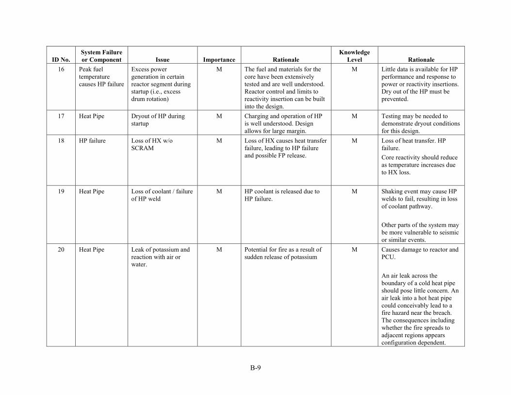
B-9
ID No. System Failure or Component Issue Importance Rationale
Knowledge Level Rationale
16 Peak fuel temperature causes HP failure
Excess power generation in certain reactor segment during startup (i.e., excess drum rotation)
M The fuel and materials for the core have been extensively tested and are well understood. Reactor control and limits to reactivity insertion can be built into the design.
M Little data is available for HP performance and response to power or reactivity insertions. Dry out of the HP must be prevented.
17 Heat Pipe Dryout of HP during startup
M Charging and operation of HP is well understood. Design allows for large margin.
M Testing may be needed to demonstrate dryout conditions for this design.
18 HP failure Loss of HX w/o SCRAM
M Loss of HX causes heat transfer failure, leading to HP failure and possible FP release.
M Loss of heat transfer. HP failure. Core reactivity should reduce as temperature increases due to HX loss.
19 Heat Pipe Loss of coolant / failure of HP weld
M HP coolant is released due to HP failure.
M Shaking event may cause HP welds to fail, resulting in loss of coolant pathway. Other parts of the system may be more vulnerable to seismic or similar events.
20 Heat Pipe Leak of potassium and reaction with air or water.
M Potential for fire as a result of sudden release of potassium
M Causes damage to reactor and PCU. An air leak across the boundary of a cold heat pipe should pose little concern. An air leak into a hot heat pipe could conceivably lead to a fire hazard near the breach. The consequences including whether the fire spreads to adjacent regions appears configuration dependent.

B-10
ID No. System Failure or Component Issue Importance Rationale
Knowledge Level Rationale
21 Inadequate heat transfer
Change in thermal conductivity of monolith
M The stainless steel has been well characterized. There does not appear to be an aging problem. This is a low-pressure system.
H The ASME Boiler and Pressure Vessel Code contains detailed property data necessary for material selection and design of elevated-temperature nuclear components.
22 Heat Pipe Buildup of impurities on condenser / evaporator
M Charging and operation of HP is well understood, as is operation.
H Heat-pipe contamination mechanisms such as diffusion within a core matrix are well characterized and if contamination develops, can be mitigated by choice of auxiliary materials that are stable with free non-metallic impurities.
23 Heat Pipe Material incompatibility
M Charging and operation of HP is well understood, as is operation. Only QA tested and approved materials would be used.
H HP tests demonstrate no corrosion or fouling.
24 Heat Pipe Oxide deposition M Charging and operation of HP is well understood, as is operation. Only QA tested materials would be used.
H Reduces ability of evaporator to transport heat.
25 Heat exchanger Water or chemical attack
M The stainless steel has been well characterized. Affects from water or other chemicals in the air can be understood.
H Properties of SS HP and HXs are well known.
26 Reactivity insertion
Dry out of HP L Loss of HP causes heat transfer failure, leading to core failure and FP release.
M Loss of heat transfer. HP failure. HP design can handle some higher power levels. Analysis is needed to determine effect of power excursions and ability to maintain temperatures.

B-11
ID No. System Failure or Component Issue Importance Rationale
Knowledge Level Rationale
27 Heat Pipe Oxide deposition L HP will be operating at a high temperature with air flowing over it. Concerns of oxidation and rate of oxidation of the SS as a result of long-term exposure to air and moisture. Does this lead to degraded heat transfer or loss of HP?
H Material aging and effects of exposure of HP at operating temperature to air and moisture need to be evaluated to determine aging and thermal transport effects.

B-12

C-1
Appendix C
Materials PIRT

C-2

C-3
Appendix C
Materials PIRT ID No. Phenomena Importance Rationale Knowledge Rationale Required R&D
1 Machining H A very large number of holes with very tight tolerances are required in the monolithic blocks if conventional wrought products are selected. Stainless steels are difficult to machine and drill.
L Direct contact with experts in machining has been limited. Alternative technologies, such as electro-discharge machining, have not been explored directly.
Demonstration with potential vendors will be required.
2 Welding H Regardless of the final manufacturing method, it will be necessary to make a large number of welds—many of which will be at the pressure boundary, thus will have to meet stringent reliability standards. Careful design will likely be required to eliminate, or minimize, the number of welds in high temperature and high stress regions.
L Conventional stainless steels have been welded in both bulk and thin wall structures for nuclear applications. Fusion welding, i.e., tungsten inert gas methods, and laser and electron beam methods are well developed. The final design is not well defined, so concerns remain about access for automated welding.
Welding processes and performance of welds as well as schemes for automated welding with very limited physical access will need to be demonstrated. Concern is not the weld, but can we weld successfully for thousands of welds that must be completed with 100% validation?
3 Inspection H If the ASME Code high temperature rules are adopted, the inspection requirements are specified. If an alternative set of rules are used, developing appropriate inspection rules would be necessary. With the complex geometry and high number of interfaces, it is not clear that methods are available for the
L Inspection methods are well established and requirements are specified in detail for code-compliant designs. Given the short design life that is envisioned, it is not clear that in-service inspection would be required. If it is deemed necessary, it is not clear that methods are available.
Successful inspection of representative test pieces with similar complex geometry and high density of interfaces will be required. The number of inspections required per segment is large and must be 100% certain.

C-4
ID No. Phenomena Importance Rationale Knowledge Rationale Required R&D entire assembly. Testing might have to be sufficient at the component level.
4 Structural design H Section III Division 5 of the ASME Code contains design rules applicable for anticipated design conditions for this reactor. These rules have not been vetted by the NRC, so it remains to be determined if this regulator will find them to be adequate. It would be possible to propose an alternative set of design rules; however, there is very limited expertise in this area for nuclear components.
L Design methods for structural components in the time-dependent material property regime are rarely used for nuclear systems. It is not clear that this reactor concept has had adequate preliminary structural design analysis. The proposed reactor design has very tight tolerances, a large number of welds and many potential stress concentrations. It is not clear that existing design rules properly address these factors.
Design analysis using sufficiently rigorous rules for nuclear components needs to be carried out on the preliminary design. Additional property characterization for weldments or powder metallurgy products may be required. Structural testing of critical features in the design may be required. Answering these questions will depend on how this can be manufactured.
5 Structural weight of the core
H Proposed deployment of the reactor is that the core is operated in a horizontal position. The ability of the lower monolith webs and sector steel to support the weight of the fuel and the balance of the sector/core mass above is uncertain, especially at operating temperature, where the SS monolith may have reduced strength.
L Analysis of the core design is needed to determine the ability of the monolith web to support the weight of the system without deformation. Supporting test data should be obtained to support the analysis.
6 Seismic event H The reactor may be subjected to seismic events that shake the reactor horizontally and vertically. The additional forces may over-stress the core structure. See item 5
L Analysis of the core design is needed to determine the ability of the monolith web to support the core weight plus the seismic forces without deformation. Supporting test

C-5
ID No. Phenomena Importance Rationale Knowledge Rationale Required R&D above “Structural weight of the core”.
data should be obtained to support the analysis.
7 Transient and off normal conditions
H Thermal transients associated with reactor transients and off-normal conditions could result in local or general temperatures being reached where the material properties are not sufficient. This could result in either structural issues and/or accelerated corrosion.
M These conditions are still subject to investigation through modeling. Design dependent, but a lot of certainty exists in material and modelling capability.
8 Thermal expansion H Because of the temperature gradients in the core, the amount of thermal expansion of the SS monolith will vary. This may cause some sections of the monolith steel to be subjected to strain or stress forces within the web thickness.
M Thermal calculations of the monolith and fuel are needed to determine if stress and strain forces are significant in the core or if any bending or warping of the core is possible during long-term operation or anticipated reactor transients.
9 Thermal creep H High-temperature components will change shape over time due to thermal creep. The stainless steel monolith will operate at high temperature. SS and UO2 masses will load the monolith structure, possibly accelerating the effects of creep.
M Database for SS316 thermal creep is well-known. Thermal analysis would need to address the SS monolith to determine if there is any appreciable change to the monolith structure that does not adversely affect the core neutronics or power generation.
10 Non-traditional manufacturing
M Powder processing, by either hot isostatic pressing (HIP) or additive manufacturing, is being considered for some LWR nuclear applications. Type 316 stainless steel HIP product form is allowed for
L Powder-based components are not code allowed in the range of irradiation exposures (i.e., 1.5 dpa) expected for this application. Where powder products are allowed for code
Demonstration of the ability to form complex components with minimal machining needs to be done. Irradiation performance in the 1.5 dpa range needs to be demonstrated.
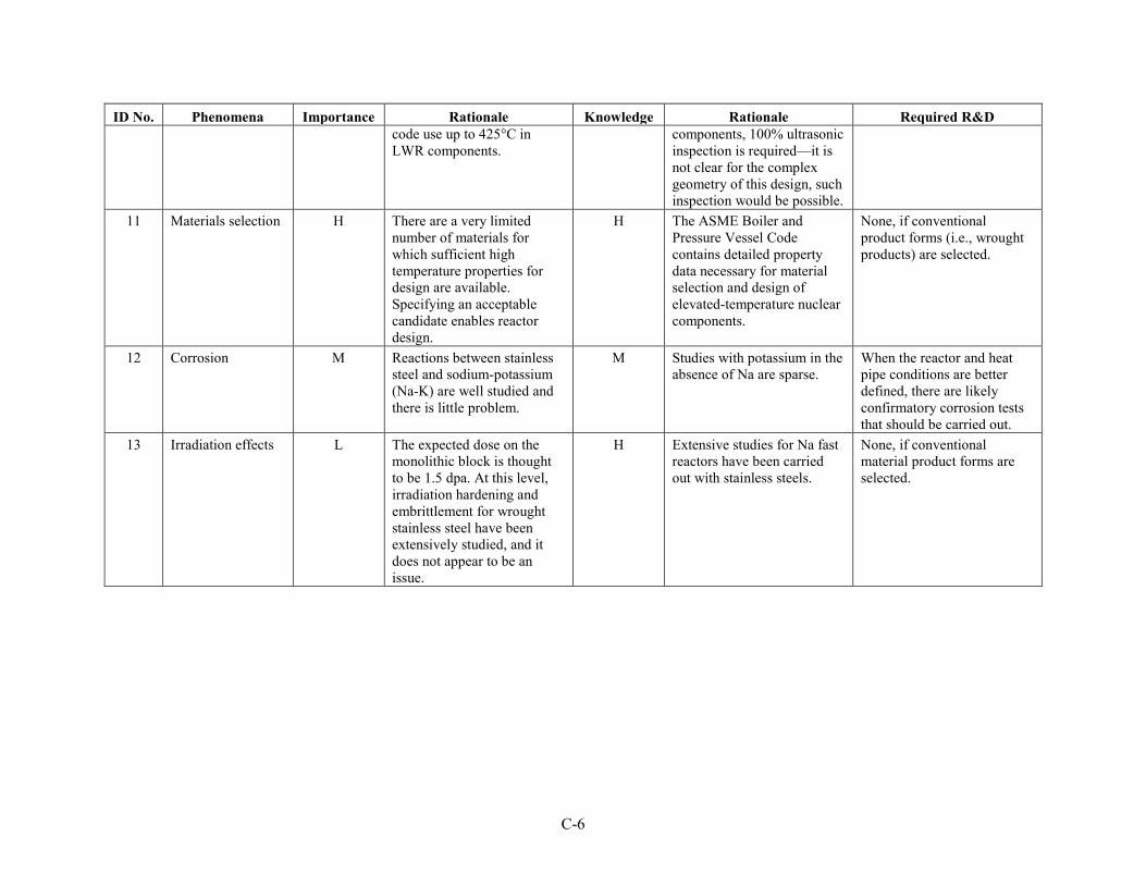
C-6
ID No. Phenomena Importance Rationale Knowledge Rationale Required R&D code use up to 425°C in LWR components.
components, 100% ultrasonic inspection is required—it is not clear for the complex geometry of this design, such inspection would be possible.
11 Materials selection H There are a very limited number of materials for which sufficient high temperature properties for design are available. Specifying an acceptable candidate enables reactor design.
H The ASME Boiler and Pressure Vessel Code contains detailed property data necessary for material selection and design of elevated-temperature nuclear components.
None, if conventional product forms (i.e., wrought products) are selected.
12 Corrosion M Reactions between stainless steel and sodium-potassium (Na-K) are well studied and there is little problem.
M Studies with potassium in the absence of Na are sparse.
When the reactor and heat pipe conditions are better defined, there are likely confirmatory corrosion tests that should be carried out.
13 Irradiation effects L The expected dose on the monolithic block is thought to be 1.5 dpa. At this level, irradiation hardening and embrittlement for wrought stainless steel have been extensively studied, and it does not appear to be an issue.
H Extensive studies for Na fast reactors have been carried out with stainless steels.
None, if conventional material product forms are selected.

D-1
Appendix D
Power Conversion Unit and HXs PIRT

D-2

D-3
Appendix D
Power Conversion Unit and HXs PIRT
ID No. System Failure or
component Issue Importance Rationale Knowledge
Level Rationale 1 Turbine/Compressor Catastrophic failure H The turbine pulls in foreign
objects or is damaged by natural disasters or deliberate attack, the objects damage the blades to the point of creating additional shrapnel that is sent to the heat pipe/air HX. The shrapnel damages the heat pipes, which releases radioactive materials to the atmosphere.
L The primary danger is that the cycle is open to the air. If the heat pipes are damaged, how can the radioactive materials be contained?
2 Air/Heat pipe HX Catastrophic failure H HX no longer functions and heat from the heat pipes cannot exchange with the air.
L If the airflow within the HX becomes blocked, alternatives need to be considered. The heat pipes are embedded within the heat exchange, so bypass may not be possible.
3 Breach Heat pipes either crack or are sheared off
H Based on current design, part of the heat pipe wall is the monolith, which is close to the fuel pins. The potassium within the heat pipe could be radioactive. If a heat pipe should break, the potassium would mix with the air and would be ejected directly by the power cycle into the atmosphere.
M Another boundary should be implemented to separate the power cycle from the fuel. This could be in the form of an intermediate heat transfer loop. Another solution could be to close the PCU cycle so that the working fluid is not directly in contact with the atmosphere.
4 Heat exchangers Thermal creep M The HXs could change in size due to thermal creep; however, these units should be smaller in volume and the thermal
H CFD and stress analysis may be used to understand the effects of thermal creep. Also working with commercial HX

D-4
ID No. System Failure or
component Issue Importance Rationale Knowledge
Level Rationale expansion/compression will have a lesser effect.
manufacturers may resolve many of the issues based on their experience. The temperature seen within these HXs is not outside of the design experience of commercial manufacturers.
5 Power cycle Contaminants M Pollutions and other contaminants may corrode turbine and HXs
M Analyses of adverse conditions on the materials may need to occur to predict corrosion.
6 Generator Failure M The generator fails and is not able to produce electrical power from the turbine’s shaft power.
?
7 Power cycle Ambient conditions L Temperature, pressure (elevation), and humidity affect the power cycle performance.
L Decades of experience and modeling techniques may be used to predict power cycle performance as a function of the ambient conditions.
8 Recuperating HX Catastrophic failure M The HX is sufficiently damaged and the fluid on both sides of the HX interacts with each other. The heat exchanger is an air to air recuperator using atmospheric air as the fluid. So long as air is flowing, the heat pipes should have sufficient cooling to continue functioning. The power produced will likely drop substantially.
H Means can be developed to bypass this HX completely. This will reduce power production, but it would provide the sufficient cooling needed for the heat pipes.
9 Turbine/Compressor Fails M If the power conversion unit (PCU) fails, there is no heat sink; however, the heat pipes would still transfer the air.
H Air Brayton cycles are well understood and should have high reliability. If failure occurs, an emergency air blower could move air through the HP/air heat exchanger (HX) to remove the heat from the HPs, or the HX

D-5
ID No. System Failure or
component Issue Importance Rationale Knowledge
Level Rationale could be designed to work with natural convection.
10 Recuperating HX Thermal stresses M The recuperating HX will see large thermal gradients between the inlet and the outlet. These stresses may deform or crack the HX, which could mix streams. The HX is an air-to-air HX; therefore, this failure should only affect the transfer of heat to the power cycle, which in turn may reduce power production.
H Finite element analysis on the HX design should determine the thermal stresses within. If the thermal stresses are an issue the design could be changed to reduce the stresses, which could include new material selection and multiple HXs. This type of HX should be common in the power industry and many of these issues already solved.
11 Heat pipe HX Thermal stresses M The thermal gradients across the heat pipe HX will be low under normal operation if the heat pipes are nearly isothermal and the HX insulated well. If heat pipes fail, the thermal stresses will increase because the thermal gradients will also rise.
H CFD and stress analysis can be performed for the normal operation and for heat pipe failure to determine stresses within the HX.
12 Turbine/Compressor Materials L Commercial natural gas turbines reach temperatures approaching 1400°C. The reactor will be well below these temperatures. Radiation may have some effect on the materials, but it is hoped that no radiation is present within the PCU.
H Air Brayton cycles have decades of commercial experience. Materials have been selected to reach high temperatures. These components are not subject to ASME design rules and associated limits on allowable materials.
13 Recuperating HX & heat pipe HX
Pressure stresses L The pressure difference between the hot side and cold side of the recuperating and heat pipe HXs should be no more than 30 psig.
H Finite element analysis on the HX design should determine the mechanical stresses within. It is highly unlikely that pressure will cause failure of the HXs.

D-6

E-1
Appendix E
Thermal and Structural Analysis

E-2

E-3
Appendix E
Thermal and Structural Analysis Highlights from a preliminary Idaho National Laboratory thermal and structural analysis of the
Los Alamos National Laboratory (LANL) Special Purpose Reactor are documented and discussed in this appendix. This thermal and structural evaluation and the models constructed for the analyses are based on the reactor design parameters listed above in Table 1. This analysis seeks to examine the thermal and structural aspects of the initial LANL design.
Results of the analyses uncovered significant concerns with this core design, in particular the steel monolith. In the nominal or normal anticipated steady-state reactor operating condition, the thin webbings of the Type 316 stainless steel (SS) monolith structure are subjected to elevated temperatures and thermal expansions that induce significant thermal stresses. These high-stress regions occur between every single fuel pin, i.e., the 1.75 mm thick steel webbings between fuel pins. Maximum stresses in these webs occur in those webs at core mid-plane and towards the radial center of the core where the maximum volumetric fission heat rates occur. These maximum stresses are beyond the allowable stresses in the ASME code.
As heat pipes fail, the stress situation only gets worse, and it is quite likely that the monolith structure yields, although that specific analysis has not yet been performed. Additionally, as heat pipes fail, the monolith temperatures exceed those allowed by the ASME code. Thermal creep under these temperatures and stresses is expected to be a problem as well, although it too was not analyzed.
Plus, there are substantial thermal gradients and heat fluxes in the thinnest 1 mm steel webbings between the heat pipes and the fuel pins; however, these induced stresses are less than those between fuel pins.
One other concern is the ability of the monolith to support its own weight as well as the weight of the fuel and heat pipes. However, since the present analysis here shows significant stresses without weight forces being considered, this additional stress is expected to further exacerbate the problem.

E-4

E-5
CONTENTS
E-1. SCOPE AND BRIEF DESCRIPTION ........................................................................................... E-9
E-2. DESIGN OR TECHNICAL PARAMETER INPUT AND SOURCES ......................................... E-9
E-3. MODEL ASSUMPTIONS ............................................................................................................. E-9
E-4. COMPUTER HARDWARE AND SOFTWARE .......................................................................... E-9
E-5. ABAQUS MODEL DEVELOPMENT .......................................................................................... E-9 E-5.1 Abaqus Geometry and Mesh .............................................................................................. E-10 E-5.2 Initial and Boundary Conditions ........................................................................................ E-13
E-5.2.1 Thermal Model ...................................................................................................... E-13 E-5.2.2 Structural Model ................................................................................................... E-14 E-5.2.3 Heat Loads ............................................................................................................ E-14
E-6. RESULTS ..................................................................................................................................... E-14 E-6.1 Nominal Condition ............................................................................................................. E-14
E-6.1.1 Fuel Temperatures................................................................................................. E-14 E-6.1.2 Monolith Temperatures ......................................................................................... E-16 E-6.1.3 Monolith Heat Flux ............................................................................................... E-17 E-6.1.4 Monolith Stress and Strain .................................................................................... E-19 E-6.1.5 Thermal Expansion ............................................................................................... E-21 E-6.1.6 Summary ............................................................................................................... E-23
E-6.2 One Failed Heat Pipe ......................................................................................................... E-24 E-6.2.1 Fuel Temperatures................................................................................................. E-25 E-6.2.2 Monolith Temperatures ......................................................................................... E-27 E-6.2.3 Monolith Heat Flux ............................................................................................... E-28 E-6.2.4 Monolith Stress and Strain .................................................................................... E-29 E-6.2.5 Thermal Expansion ............................................................................................... E-31 E-6.2.6 Summary ............................................................................................................... E-33
E-6.3 Two Failed Heat Pipes ....................................................................................................... E-34 E-6.3.1 Fuel Temperatures................................................................................................. E-34 E-6.3.2 Monolith Temperatures ......................................................................................... E-36 E-6.3.3 Monolith Heat Flux ............................................................................................... E-37 E-6.3.4 Monolith Stress and Strain .................................................................................... E-38 E-6.3.5 Thermal Expansion ............................................................................................... E-40 E-6.3.6 Summary ............................................................................................................... E-42
E-6.4 Three Failed Heat Pipes ..................................................................................................... E-43 E-6.4.1 Fuel Temperatures................................................................................................. E-43 E-6.4.2 Monolith Temperatures ......................................................................................... E-45 E-6.4.3 Monolith Heat Flux ............................................................................................... E-46 E-6.4.4 Monolith Stress and Strain .................................................................................... E-47 E-6.4.5 Thermal Expansion ............................................................................................... E-49 E-6.4.6 Summary ............................................................................................................... E-51

E-6
E-7. SUMMARY AND CONCLUSIONS ........................................................................................... E-52
E-8. REFERENCES ............................................................................................................................. E-53
FIGURES Figure E-1. Cross-sectional view of the LANL Special Purpose Reactor core. ......................................... 10
Figure E-2. Abaqus model geometry of a single 60° reactor core sector. .................................................. 11
Figure E-3. Axial cross-section view of a 60° reactor core sector. ............................................................. 12
Figure E-4. Heat pipe and fuel pin numbering scheme. .............................................................................. 13
Figure E-5. Transverse cross-section of nominal condition monolith and fuel mid-plane temperatures (units in K). ........................................................................................................... 15
Figure E-6. Axial cross-section of nominal condition monolith and fuel centerline temperatures (units in K). ................................................................................................................................. 16
Figure E-7. Transverse cross-section of nominal condition monolith mid-plane temperatures (units in K). ................................................................................................................................. 17
Figure E-8. Transverse cross-section of nominal condition monolith mid-plane heat flux (units in W/m2). ......................................................................................................................................... 18
Figure E-9. Transverse cross-section of nominal condition monolith mid-plane Mises stresses (units in Pa). ................................................................................................................................ 19
Figure E-10. Transverse cross-section of nominal condition monolith mid-plane strain (units in strain). ......................................................................................................................................... 20
Figure E-11. Radial thermal expansion under nominal conditions (units in m). ........................................ 21
Figure E-12. Axial thermal expansion under nominal conditions (units in m). .......................................... 22
Figure E-13. Total thermal expansion under nominal conditions (units in m). .......................................... 23
Figure E-14. Transverse cross-section of 1 failed heat pipe condition monolith and fuel mid-plane temperatures (units in K). ........................................................................................................... 25
Figure E-15. Axial cross-section of 1 failed heat pipe condition monolith and fuel centerline temperatures (units in K). ........................................................................................................... 26
Figure E-16. Transverse cross-section of 1 failed heat pipe condition monolith mid-plane temperatures (units in K). ........................................................................................................... 27
Figure E-17. Transverse cross-section of 1 failed heat pipe condition monolith mid-plane heat flux (units in W/m2). ................................................................................................................... 28
Figure E-18. Transverse cross-section of 1 failed heat pipe condition monolith mid-plane Mises stresses (units in Pa). .................................................................................................................. 29
Figure E-19. Transverse cross-section of 1 failed heat pipe condition monolith mid-plane strain (units in strain). ........................................................................................................................... 30
Figure E-20. Radial thermal expansion under 1 failed heat pipe conditions (units in m). .......................... 31
Figure E-21. Axial thermal expansion under 1 failed heat pipe conditions (units in m). ........................... 32
Figure E-22. Total thermal expansion under 1 failed heat pipe conditions (units in m). ............................ 33

E-7
Figure E-23. Transverse cross-section of 2 failed heat pipe condition monolith and fuel mid-plane temperatures (units in K). ........................................................................................................... 34
Figure E-24. Axial cross-section of 2 failed heat pipe condition monolith and fuel centerline temperatures (units in K). ........................................................................................................... 35
Figure E-25. Transverse cross-section of 2 failed heat pipe condition monolith mid-plane temperatures (units in K). ........................................................................................................... 36
Figure E-26. Transverse cross-section of 2 failed heat pipe condition monolith mid-plane heat flux (units in W/m2). ................................................................................................................... 37
Figure E-27. Transverse cross-section of 2 failed heat pipe condition monolith mid-plane Mises stresses (units in Pa). .................................................................................................................. 38
Figure E-28. Transverse cross-section of 2 failed heat pipe condition monolith mid-plane strain (units in strain). ........................................................................................................................... 39
Figure E-29. Radial thermal expansion under 2 failed heat pipe conditions (units in m). .......................... 40
Figure E-30. Axial thermal expansion under 2 failed heat pipe conditions (units in m). ........................... 41
Figure E-31. Total thermal expansion under 2 failed heat pipe conditions (units in m). ............................ 42
Figure E-32. Transverse cross-section of 3 failed heat pipe condition monolith and fuel mid-plane temperatures (units in K). ........................................................................................................... 43
Figure E-33. Axial cross-section of 3 failed heat pipe condition monolith and fuel centerline temperatures (units in K). ........................................................................................................... 44
Figure E-34. Transverse cross-section of 3 failed heat pipe condition monolith mid-plane temperatures (units in K). ........................................................................................................... 45
Figure E-35. Transverse cross-section of 3 failed heat pipe condition monolith mid-plane heat flux (units in W/m2). ................................................................................................................... 46
Figure E-36. Transverse cross-section of 3 failed heat pipe condition monolith mid-plane Mises stresses (units in Pa). .................................................................................................................. 47
Figure E-37. Transverse cross-section of 3 failed heat pipe condition monolith mid-plane strain (units in strain). ........................................................................................................................... 48
Figure E-38. Radial thermal expansion under 3 failed heat pipe conditions (units in m). .......................... 49
Figure E-39. Axial thermal expansion under 3 failed heat pipe conditions (units in m). ........................... 50
Figure E-40. Total thermal expansion under 3 failed heat pipe conditions (units in m). ............................ 51
TABLES Table E-1. Temperature result summary. .................................................................................................... 52
Table E-2. Thermally induced stress and strain result summary. ............................................................... 52
Table E-3. Thermal expansion summary. ................................................................................................... 53

E-8

E-9
E-1. SCOPE AND BRIEF DESCRIPTION A megawatt scale, heat pipe-cooled fast reactor has been proposed for potential use in unique
situations where other means of power generation are unavailable or impractical. This concept, initially proposed by LANL is being evaluated using the Phenomena Identification and Ranking Technique (PIRT) to help determine potential areas of the design requiring further investigation. This analysis seeks to examine the thermal and structural aspects of the initial LANL design.
E-2. DESIGN OR TECHNICAL PARAMETER INPUT AND SOURCES The thermal models are based on the LANL Special Purpose Reactor conceptual design.1
Dimensions, materials, and other input parameters are based on the Table 2 data above and data collected through correspondence with LANL. Abaqus models were constructed by INL for the thermal and stress analysis evaluation of the LANL reactor concept.2
E-3. MODEL ASSUMPTIONS 1. Due to the complexity of the reactor, only one of the six 60° reactor core sectors was modeled. Each
sector is assumed to operate in a nominally similar way from a thermal-structural perspective.
2. The heat pipes are not explicitly modeled. Instead, a constant temperature boundary condition of 677°C (950.15 K) was prescribed at the boundaries where the heat pipes contact the monolith and upper reflector.
3. For the analysis of failed heat pipes, the 677°C (950.15 K) constant temperature boundary condition was removed and replaced with an adiabatic boundary condition. This simulates a worst-case scenario of no heat transfer through or out the failed heat pipe.
4. All models assume a steady-state operation. No transient events are considered in this evaluation.
5. All materials are assumed elastic throughout the simulations. No plasticity models have been incorporated. This allows for a simplified analysis to determine if the model exceeds stress limits.
E-4. COMPUTER HARDWARE AND SOFTWARE • Computer type: 19,872-core SGI ICE X distributed memory system. 828 Compute Nodes with 2,
12-core Intel Xeon E5-2680 v3 2.5GHz processors and 128-GB RAM per node.
• Operating System and Version: SUSE LINUX Enterprise Server 11 (x86_64) SP3
• Computer program name and revision: ABAQUS 2016 Standard
• Validation: ABAQUS is listed in the INL EA repository of qualified scientific and engineering analysis software (EA Identifier 238858).
E-5. ABAQUS MODEL DEVELOPMENT The INL thermal and structural analysis is focused primarily on the stainless steel monolith core that
houses the fuel pins and acts as a heat transfer medium to the heat pipes. Figure E-1 shows a cross-section through the monolith section. The monolith is comprised of six 60° reactor core sectors arranged in a hexagonal geometry with a central hexagonal volume. The central hexagonal volume was assumed empty, a position that is intended to accommodate the emergency shutdown control rods. The blue circles in the figure represent the fuel pins (352 per sector) and the white circles represent the heat pipes (204 per sector). In order to simplify the analysis, only a single sector is considered here with an adiabatic boundary condition applied to the outer radial and azimuthal surfaces.

E-10
Figure E-1. Cross-sectional view of the LANL Special Purpose Reactor core.
E-5.1 Abaqus Geometry and Mesh The Abaqus model consists of four main structural components: (1) gas plenum, (2) lower reflector,
(3) monolith, and (4) upper reflector. These four components are shown in Figure E-2. Note that while the structure is shown vertically in Figure E-2, the actual reactor is in a horizontal orientation. The same mesh was used for both the thermal and structural models. In addition to the structural components, the thermal models also included 352 fuel pin components.

E-11
Figure E-2. Abaqus model geometry of a single 60° reactor core sector.
The fuel pins are in the monolith section. Holes for heat pipes pass through the upper reflector and monolith. The lower reflector is represented here as a solid steel block, while in reality it would have small holes to allow access from the fuel pins to the gas plenum and beryllium oxide reflector pellets below the UO2 fuel pins. Figure E-3 shows a cross-section of the model geometry, with the fuel pins in red, fuel pin gas gap helium in green (not visible in figures), and all stainless steel components in beige.
Upper Reflector• Holes for Heat Pipes
Monolith• Holes for Heat Pipes• Holes for Fuel Pins
Lower Reflector• No holes
Gas Plenum• Holes for Helium
Bottom Plate• No Holes

E-12
Figure E-3. Axial cross-section view of a 60° reactor core sector.
To help in identification of components for mapping of heat loads, a numbering system was developed for the heat pipes and fuel pins. The fuel pins and heat pipes are numbered by snaking down the columns from the inner boundary to the outer boundary of the monolith. Figure E-4 shows a cross section of the monolith with the fuel colored red and the monolith beige. Some heat pipes and fuel numbers are called out to help illustrate the numbering scheme.
Core Center
Upper Reflector
Monolith
Lower Reflector
Gas Plenum

E-13
Figure E-4. Heat pipe and fuel pin numbering scheme.
E-5.2 Initial and Boundary Conditions E-5.2.1 Thermal Model
The thermal model includes a constant temperature boundary condition of 677°C (950.15 K) on the monolith and upper reflector surfaces where the heat pipes are active. In order to simulate a failed heat pipe, this boundary condition is removed from the heat pipe, resulting in an adiabatic boundary. Further details on this process are provided in the next section. Additionally, all exterior surfaces of the model are assumed adiabatic.
HP-1
HP-4
HP-5
HP-9
Fuel-1
Fuel-3
Fuel-4
Fuel-7
Fuel-8
Fuel-11
HP-204Fuel-352
HP-185Fuel-334
Fuel-12
Fuel-16

E-14
In the analysis of 1 failed heat pipe, the constant temperature thermal boundary condition for heat pipe 7 was changed to an adiabatic condition.
In the analysis of 2 failed heat pipes, the constant temperature thermal boundary condition for heat pipes 7 and 12 were changed to an adiabatic condition. This simulates a cascade failure where the loss of one heat pipe causes the neighboring heat pipe to fail.
In the analysis of 3 failed heat pipes, the constant temperature thermal boundary condition for heat pipes 7, 12, and 13 were changed to an adiabatic condition. This simulates a worst-case failure where all three heat pipes in a triad around the hottest fuel pin fail.
E-5.2.2 Structural Model The structural model takes the temperatures from the thermal models as input and determines the
resulting stresses, heat fluxes, and thermal expansion. The model assumes an initial temperature of 300 K (27°C). All resulting thermal stresses and expansion are determined based on the temperature change from this initial temperature. For the thermal expansion calculation, the lower surface of the model, which corresponds to the bottom of the reactor gas plenum region, is fixed. Axial expansions are measured from this fixed bottom surface and radial expansions are measured from the inner reactor core surface outward.
E-5.2.3 Heat Loads Heat loads were provided from the neutronics analysis. Volumetric heat rates were provided at 6 axial
locations for each of the 352 fuel pins. A python script was used to generate a fifth order polynomial for the volumetric heat rate on each pin as a function of axial location. These polynomials were then read into an Abaqus FORTRAN subroutine and used to determine the local volumetric heat rate at all fuel mesh locations.
E-6. RESULTS E-6.1 Nominal Condition
For the nominal operating condition, all heat pipes are assumed to be operational. The heat loads from the neutronics analysis were read into the Abaqus model using a FORTRAN subroutine. A steady state thermal analysis was then performed. The temperature results from the thermal analysis were then mapped into a structural analysis.
E-6.1.1 Fuel Temperatures Figure E-5 and Figure E-6 show cross-sections of the temperature distributions in the fuel and
monolith for the nominal operating condition.

E-15
Figure E-5. Transverse cross-section of nominal condition monolith and fuel mid-plane temperatures (units in K).

E-16
Figure E-6. Axial cross-section of nominal condition monolith and fuel centerline temperatures (units in K).
E-6.1.2 Monolith Temperatures To get a better understanding of the temperature distributions in the monolith, Figure E-5 was
re-plotted with the fuel removed. This plot of the monolith temperature distributions is shown in Figure E-7.

E-17
Figure E-7. Transverse cross-section of nominal condition monolith mid-plane temperatures (units in K).
E-6.1.3 Monolith Heat Flux In addition to temperature distributions in the monolith, heat flux, Mises stress/strain, and thermal
expansion plots were also generated as part of the structural model output.

E-18
Figure E-8. Transverse cross-section of nominal condition monolith mid-plane heat flux (units in W/m2).

E-19
E-6.1.4 Monolith Stress and Strain
Figure E-9. Transverse cross-section of nominal condition monolith mid-plane Mises stresses (units in Pa).

E-20
Figure E-10. Transverse cross-section of nominal condition monolith mid-plane strain (units in strain).

E-21
E-6.1.5 Thermal Expansion
Figure E-11. Radial thermal expansion under nominal conditions (units in m).

E-22
Figure E-12. Axial thermal expansion under nominal conditions (units in m).

E-23
Figure E-13. Total thermal expansion under nominal conditions (units in m).
E-6.1.6 Summary Under nominal or normal operating conditions, the reactor in-core steel monolith has a peak fuel
temperature of 753°C (1026 K) or 76°C above heat pipe isothermal boundary temperature of 677°C (fuel pin 14). The peak monolith temperature was 696°C (969 K) or 19°C above heat pipe isothermal boundary temperature (between fuel pins 14 and 19). Peak stresses in the monolith webbing of 3.71 × 10⁷ Pa (37.1 MPa) are seen between fuel pins 9 and 14 near core mid-plane and the core region of highest

E-24
volumetric fission heat rates. The corresponding peak strain is 1.48%. In general, the highest in-core stresses (Figure E-9) occur in the steel monolith webs between fuel pins, where the monolith web thickness is 1.75 mm. Note: the web thickness between the heat pipes and fuel pins is even thinner at 1 mm. Also, these regions of highest stress coincide with highest steel monolith temperatures (Figure E-7). Interestingly, the highest heat fluxes occur peripherally around the edge of the heat pipes and across or near the thinnest steel monolith webbings (1 mm). These same regions also have the highest thermal gradients.
The axial thermal expansion is approximately 2.98 cm. The radial thermal expansion is only about 6 mm.
E-6.2 One Failed Heat Pipe Fuel pin 14 saw the highest temperatures in the nominal operating condition. It is adjacent to heat
pipes 7, 12, and 13. In order to examine the worst-case effect of a single heat pipe failure, the constant temperature boundary condition of heat pipe 7 was disabled and replaced with an adiabatic boundary condition or no heat transfer across that heat pipe boundary.

E-25
E-6.2.1 Fuel Temperatures
Figure E-14. Transverse cross-section of 1 failed heat pipe condition monolith and fuel mid-plane temperatures (units in K).

E-26
Figure E-15. Axial cross-section of 1 failed heat pipe condition monolith and fuel centerline temperatures (units in K).

E-27
E-6.2.2 Monolith Temperatures
Figure E-16. Transverse cross-section of 1 failed heat pipe condition monolith mid-plane temperatures (units in K).

E-28
E-6.2.3 Monolith Heat Flux
Figure E-17. Transverse cross-section of 1 failed heat pipe condition monolith mid-plane heat flux (units in W/m2).

E-29
E-6.2.4 Monolith Stress and Strain
Figure E-18. Transverse cross-section of 1 failed heat pipe condition monolith mid-plane Mises stresses (units in Pa).

E-30
Figure E-19. Transverse cross-section of 1 failed heat pipe condition monolith mid-plane strain (units in strain).

E-31
E-6.2.5 Thermal Expansion
Figure E-20. Radial thermal expansion under 1 failed heat pipe conditions (units in m).

E-32
Figure E-21. Axial thermal expansion under 1 failed heat pipe conditions (units in m).

E-33
Figure E-22. Total thermal expansion under 1 failed heat pipe conditions (units in m).
E-6.2.6 Summary For the case of one heat pipe failure at the worst core position, the peak fuel temperature was 792°C
(1065 K) or 115°C above heat pipe isothermal boundary temperature of 677°C (fuel pin 9). The peak monolith temperature was 769°C (1042 K) or 92°C above heat pipe isothermal boundary temperature (around heat pipe 7). Peak stresses in the monolith webbing of 1.546 × 10⁸ Pa (154.6 MPa) are seen around the failed heat pipe 7. Peak strain is 1.59%. Thermal expansion remains approximately the same as the nominal or normal operating case.

E-34
E-6.3 Two Failed Heat Pipes To simulate a cascading failure of heat pipes, an analysis was completed with heat pipes 7 and 12
disabled in the analysis. These heat pipes represent two of the three pipes neighboring the hottest fuel pin (pin 14).
E-6.3.1 Fuel Temperatures
Figure E-23. Transverse cross-section of 2 failed heat pipe condition monolith and fuel mid-plane temperatures (units in K).

E-35
Figure E-24. Axial cross-section of 2 failed heat pipe condition monolith and fuel centerline temperatures (units in K).

E-36
E-6.3.2 Monolith Temperatures
Figure E-25. Transverse cross-section of 2 failed heat pipe condition monolith mid-plane temperatures (units in K).

E-37
E-6.3.3 Monolith Heat Flux
Figure E-26. Transverse cross-section of 2 failed heat pipe condition monolith mid-plane heat flux (units in W/m2).

E-38
E-6.3.4 Monolith Stress and Strain
Figure E-27. Transverse cross-section of 2 failed heat pipe condition monolith mid-plane Mises stresses (units in Pa).

E-39
Figure E-28. Transverse cross-section of 2 failed heat pipe condition monolith mid-plane strain (units in strain).

E-40
E-6.3.5 Thermal Expansion
Figure E-29. Radial thermal expansion under 2 failed heat pipe conditions (units in m).

E-41
Figure E-30. Axial thermal expansion under 2 failed heat pipe conditions (units in m).

E-42
Figure E-31. Total thermal expansion under 2 failed heat pipe conditions (units in m).
E-6.3.6 Summary For the case of two heat pipe failures, the peak fuel temperature was 866°C (1139 K) or 189°C above
heat pipe isothermal boundary temperature of 677°C (fuel pin 14). The peak monolith temperature was 845°C (1118 K) or 168°C above heat pipe isothermal boundary temperature (between fuel pins 9 and 14). Peak stresses in the monolith webbing of 1.537 × 10⁸ Pa (153.7 MPa) are seen around the failed heat pipe 12. Peak strain is 1.59%. Again the thermal expansion remains approximately the same as the nominal or normal operating case.

E-43
E-6.4 Three Failed Heat Pipes For the case of three failed heat pipes or a worst-case scenario of three neighboring heat pipes failing,
an analysis was simulated with heat pipes 7, 12, and 13 disabled. These heat pipes represent the three pipes neighboring the hottest fuel pin (pin 14).
E-6.4.1 Fuel Temperatures
Figure E-32. Transverse cross-section of 3 failed heat pipe condition monolith and fuel mid-plane temperatures (units in K).

E-44
Figure E-33. Axial cross-section of 3 failed heat pipe condition monolith and fuel centerline temperatures (units in K).

E-45
E-6.4.2 Monolith Temperatures
Figure E-34. Transverse cross-section of 3 failed heat pipe condition monolith mid-plane temperatures (units in K).

E-46
E-6.4.3 Monolith Heat Flux
Figure E-35. Transverse cross-section of 3 failed heat pipe condition monolith mid-plane heat flux (units in W/m2).

E-47
E-6.4.4 Monolith Stress and Strain
Figure E-36. Transverse cross-section of 3 failed heat pipe condition monolith mid-plane Mises stresses (units in Pa).

E-48
Figure E-37. Transverse cross-section of 3 failed heat pipe condition monolith mid-plane strain (units in strain).

E-49
E-6.4.5 Thermal Expansion
Figure E-38. Radial thermal expansion under 3 failed heat pipe conditions (units in m).

E-50
Figure E-39. Axial thermal expansion under 3 failed heat pipe conditions (units in m).

E-51
Figure E-40. Total thermal expansion under 3 failed heat pipe conditions (units in m).
E-6.4.6 Summary For the three heat pipe failure simulation, the peak fuel temperature was 1009°C (1282 K) or 335°C
above heat pipe isothermal boundary temperature of 677°C (fuel pin 14). The peak monolith temperature was 937°C (1210 K) or 260°C above heat pipe isothermal boundary temperature (between heat pipe 13 and fuel pin 14). Peak stresses in the monolith webbing of 3.204 × 10⁸ Pa (320.4 MPa) were calculated around fuel pin 14. Peak strain is 1.76%. Again the thermal expansion remains approximately the same as the nominal or normal operating case.

E-52
E-7. SUMMARY AND CONCLUSIONS With heat pipe failures, there are substantial increases in temperature for both the fuel and monolith.
The ASME code provides data for SS316 to a maximum temperature of 825°C (1148 K).3 Results in Table E-1 show the monolith exceeds this temperature in the case of three failed heat pipes.
Table E-1. Temperature result summary.
Operating Condition
Peak Fuel Temperature Peak Monolith Temperature
Location Temperature
Change from Nominal
Location Temperature
Change from Nominal
(°C) (K) (%) (°C) (K) (%) Nominal Pin 14 753 1026 — Pins 14 and
19 696 969 —
1 Failed HP Pin 9 792 1065 3.80% HP 7 769 1042 7.53% 2 Failed HP Pin 14 866 1139 11.01% Pins 9 and 14 845 1118 15.38% 3 Failed HP Pin 14 1009 1282 24.95% HP 13 and
Pin 14 937 1210 24.87%
Even under nominal operating conditions, the thin webbing of the monolith results in large thermal
stresses. Table E-2 shows that for the nominal condition, a stress of 37.1 MPa is calculated between two fuel pins. From Table E-1, this stress appears to occur at a temperature of 696°C (969 K). In the ASME code at a temperature of 700°C, the maximum allowable stress is 29.6 MPa. The nominal operating condition exceeds this limit by 25%. As heat pipes fail, the thermally induced stress increases significantly. For a single heat pipe failure, the maximum calculated stress jumps to 154.6 MPa, far exceeding the allowable level. More heat pipe failures, either locally or distributed, only exacerbates the problem.
It should be noted that the simulation assumed a linear-elastic model for the SS316 properties, and plasticity was not considered. Since the results exceed the ASME limits, a plastic analysis would be required to fully understand the behavior of the monolith above the code limitations.
Table E-2. Thermally induced stress and strain result summary.
Operating Condition
Peak Mises Stress Peak Strain
Location Stress (MPa)
Change from Nominal
(%) Strain (%)
Change from Nominal
(%) Nominal Pins 9 and 14 37.1 — 1.48% — 1 Failed HP HP 7 154.6 316.71% 1.59% 7.43% 2 Failed HP HP 12 and Pin 14 153.7 314.29% 1.59% 7.43% 3 Failed HP HP 13 and Pin 14 320.4 763.61% 1.76% 18.92%
Thermal expansion of the entire structure—monolith, reflectors, and gas plenum—was also
considered. Table E-3 shows the radial, axial, and total elongation in the four cases under consideration. The loss of up to three heat pipes appears to have minimal impact on the total thermal elongation of the monolith structure.

E-53
Table E-3. Thermal expansion summary. Operating Condition
Max Radial Elongation (m)
Max Axial Elongation (m)
Max Total Elongation (m)
Nominal 6.04E-03 2.89E-02 2.98E-02
1 Failed HP 6.17E-03 2.89E-02 2.98E-02
2 Failed HP 6.29E-03 2.90E-02 2.98E-02
3 Failed HP 6.44E-03 2.90E-02 2.99E-02
E-8. REFERENCES 1. P. McClure, D. Poston, D.V. Rao and R. Reid, Design of Megawatt Power Level Heat Pipe Reactors,
LA-UR-15-28840 (Los Alamos, NM: LANL, 2015).
2. Dassault Systèmes, ABAQUS Standard 2016 Data Sheet, accessed January 5, 2017, http://www.3ds.com/fileadmin/PRODUCTS/SIMULIA/PDF/datasheets/simulia-abaqus-standard-datasheet.pdf.
3. ASME Boiler and Pressure Vessel Committee on Materials, “2015 ASME Boiler and Pressure Vessel Code,” in Section II, Part D (Metric), (New York: The American Society of Mechanical Engineers, 2015), 70–85.
4. National Institute of Standards and Technology, NIST Chemistry WebBook, accessed August 4, 2016, http://webbook.nist.gov/chemistry.
5. F.P. Incropera, D.P. DeWitt, T.L. Bergman and A.S. Lavine, Introduction to Heat Transfer, 5th ed. (Hoboken, NJ: John Wiley & Sons, Inc., 2007).

E-54

F-1
Appendix F
Neutronic Analysis

F-2

F-3
Appendix F
Neutronic Analysis Highlights from a preliminary INL neutronic analysis of the LANL Special Purpose Reactor are
documented and discussed in this appendix. The neutronic evaluation is based on the reactor design parameters listed in Table 1 above. Initially, two independent MCNP computer models1 of the reactor were constructed by INL analysts. Calculated results from these models are presented and include sensitivity analyses, depletion calculations, control drum/rod worth, reactivity calculations, etc. The conceptual nature of the LANL design required a few reasonable assumptions on the part of the INL to fill in design data that was not provided in reference.2
The two independent INL MCNP models were constructed using two different MCNP modeling options: (1) repeated structures and (2) explicit cell definition for each individual core component. The latter model constructs required more lines of cell definition input and consequently were somewhat larger in size. The two models were verified against each other through k-effective comparisons for identical core configurations. In addition, both models calculated core eigenvalues very close to those published by LANL, along with other published results. The verification process provided a solid starting point for all subsequent INL analyses.
The INL MCNP reactor models consist of a stainless steel monolith structure loaded with 5.22 MT of 19.75% enriched UO2 fuel with liquid potassium-loaded heat pipes for cooling and heat transfer, as shown in Figure F-1. The reactor is separated into 6 symmetrical 60° sectors, each with 352 fuel pins and 204 heat pipes (HPs) for a core total of 2,112 and 1,224, respectively. Figure F-2 shows each HP surrounded by 6 fuel pins and each fuel pin adjacent to 3 HPs. The reactor is surrounded by an Al2O3 reflector containing 12 rotatable control drums for reactivity control. Each drum contains a 90% (B-10) enriched B4C arc, and the core is designed to operate at 5 MW(t) for 5 years.
The primary regulating reactivity control is through the use of 12 control drums (CDs). These rotatable drums each have a B4C arc with a maximum thickness of 2 cm. The LANL base design calls for an enrichment of 90% B-10 in this arc, although lower B-10 enrichments should work as well. Table F-1 shows how the individual and total CD worth is affected by decreasing the B-10 enrichment. As the enrichment drops down to 10% B-10, the individual and total worth of the drums decreases by approximately $0.47 and $5.43, respectively. With a desired shutdown margin (SDM) of around 5% (𝑘𝑘𝑒𝑒𝑒𝑒𝑒𝑒~0.95), the control drums can still achieve this with a reduction down to 30% B-10. INL also assumed two emergency shutdown rods in the central hexagonal volume at core center (since at least two independent control systems would be required in any design). One shutdown rod was a solid rod; the second shutdown rod was an annular tube that surrounded the first. Radial dimensions for these two control rods are given in Table 1 above. Both rods were assumed to be boron carbide with a 90% B-10 enrichment.
Table F-2 below shows the core eigenvalues as the CD enrichment changes for the cases: (1) all poisons inserted, (2) individual control poison insertion, and (3) all poisons withdrawn. Note: the enrichment of the solid rod and annular tube remains at 90% B-10. In Table F-2, “all poisons in” means all 12 CDs rotated in and both emergency shutdown rods inserted for maximum negative reactivity insertion into the core. An important conclusion from these control studies is that the excess core reactivity can be increased, if needed, by about 500 pcm (percent milli or 1.0E-05) by simply decreasing the B-10 enrichment in the CDs and still maintaining an adequate shutdown margin.

F-4
The two CDs in each core sector could potentially be linked together and operate independently of the other five control drum banks, thus creating six independent CD pairs; however, at the nominal 90% enrichment, any 5 of the 12 CDs can make the core subcritical. In fact, all combinations of only 4 CDs can also make the core subcritical as long as the 4 drums are not adjacent to one another.
If the core were immersed in light water under certain postulated accident conditions—for example, if air gaps between core sectors and reflector were filled with water, and central hexagonal volume was filled with water, and the outer reflector was surrounded by water—the CDs alone could still keep the reactor in a sub-critical state with a SDM over $3.00. However, if there is a breach in multiple HPs, such that the heat channels in the core fill with light water, core criticality is reached with a minimum of 27 flooded HPs. With the central annular tube also inserted, criticality is reached when 49 HPs flood. Heat pipe flooding and, therefore, heat pipe integrity is an important concern.
Figure F-1. MCNP model of special purpose reactor with optional SS vessel (green) and outer B4C shield.
Figure F-2. MCNP lattice of heat pipes (yellow) surrounded by fuel pins (red).

F-5
Table F-1. Control drum worth as the B-10 enrichment is decreased.
CD Enrichment (% B-10) Critical Eigenvalue
CD Rotation (degrees)
Individual CD Worth ($)
Total CD Worth ($)
𝛽𝛽𝑒𝑒𝑒𝑒𝑒𝑒 = 0.0073 (~𝑎𝑎𝑎𝑎𝑎𝑎) 90 1.00047 48 -1.18 -13.83 80 1.00008 50 -1.16 -13.56 70 1.00060 51 -1.13 -13.24 60 1.00066 53 -1.11 -12.88 50 1.00043 56 -1.07 -12.43 40 1.00011 60 -1.01 -11.88 30 1.00019 65 -0.95 -11.14 20 1.00033 73 -0.87 -10.12 10 1.00018 91 -0.71 -8.40
Table F-2. Change in eigenvalue as the CD enrichment is decreased.
CD Enrichment (% B-10)
All Poisons Fully In
Control Drums Fully In
Annular B4C Rod Fully In
Solid B4C Rod Fully In
All Poisons Fully Out
90 0.82500 0.92602 0.94211 0.95601 1.02153 80 0.82746 0.92817 0.94263 0.95658 1.02207 70 0.83029 0.93066 0.94333 0.95727 1.02264 60 0.83362 0.93355 0.94422 0.95810 1.02338 50 0.83768 0.93719 0.94522 0.95907 1.02426 40 0.84291 0.94169 0.94649 0.96000 1.02540 30 0.84974 0.94772 0.94822 0.96200 1.02686 20 0.85965 0.95639 0.95074 0.96400 1.02911 10 0.87696 0.97144 0.95521 0.96900 1.03301
The primary reactivity feedback mechanisms result from the Doppler broadening of the fuel, the
thermal expansion of the fuel, and the swelling of the stainless steel (SS) monolith. These individual feedback mechanisms account for -0.1011 cents/ºC, -0.0408 cents/ºC, and -0.0634 cents/ºC, respectively, for a combined -0.2053 cents/ºC. All three are negative. For the fuel and monolith thermal expansion calculations, the respective volumes were increased accordingly, keeping the mass constant, which then resulted in a decrease in the material number density. The radial and axial increase in the steel monolith was calculated for temperatures at 600ºC (873 K) and 700ºC (973 K). At these two temperatures, the radial and axial expansions are roughly 0.5–0.6 and 1.5–1.8 cm, respectively. Table F-3 gives the reactivity changes associated with these two cases. Figure F-3 shows the eigenvalue as the UO2 temperature increases while Figure F-4 shows the eigenvalue as a function of UO2 thermal expansion.
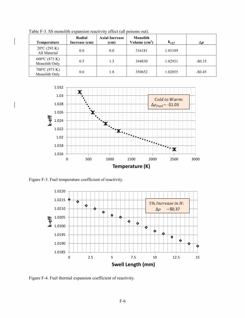
F-6
Table F-3. SS monolith expansion reactivity effect (all poisons out).
Temperature Radial
Increase (cm) Axial Increase
(cm) Monolith
Volume (cm3) 𝒌𝒌𝒆𝒆𝒆𝒆𝒆𝒆 ∆𝝆𝝆 20ºC (293 K) All Material 0.0 0.0 316181 1.03189
600ºC (873 K) Monolith Only 0.5 1.5 344830 1.02931 -$0.35
700ºC (973 K) Monolith Only 0.6 1.8 350652 1.02855 -$0.45
Figure F-3. Fuel temperature coefficient of reactivity.
Figure F-4. Fuel thermal expansion coefficient of reactivity.
1.016
1.018
1.02
1.022
1.024
1.026
1.028
1.03
1.032
0 500 1000 1500 2000 2500 3000
k-ef
f
Temperature (K)
1.0185
1.0190
1.0195
1.0200
1.0205
1.0210
1.0215
1.0220
0 2.5 5 7.5 10 12.5 15
k-ef
f
Swell Length (mm)
𝐶𝐶𝐶𝐶𝐶𝐶𝐶𝐶 𝑡𝑡𝐶𝐶 𝑊𝑊𝑎𝑎𝑊𝑊𝑊𝑊: ∆𝜌𝜌𝑒𝑒𝑓𝑓𝑒𝑒𝑓𝑓~ -$1.03
1% 𝐼𝐼𝐼𝐼𝐼𝐼𝑊𝑊𝐼𝐼𝑎𝑎𝐼𝐼𝐼𝐼 𝑖𝑖𝐼𝐼 𝐻𝐻: ∆𝜌𝜌 = −$0.37

F-7
The LANL reactor design is tightly coupled and sensitive to dimensional and material changes. Table F-4 shows the extreme sensitivity of the core reactivity by decreasing the fuel pellet radius in 0.1 mm increments. The eigenvalue in Column 7 assumes the fuel pellet radius decreases and the gas gap increases. For a 0.1 mm decrease in pellet radius, half the core reactivity is lost. The eigenvalue in the last column again assumes the pellet radius decreases while maintaining the gas gap thickness, resulting in an increase in the steel monolith mass. For this case, the reactivity impact is slightly more negative, perhaps due to an increase in the parasitic absorption of the steel. These results clearly demonstrate the very high degree of sensitivity of the core reactivity for even the slightest decrease in fuel radius. This makes it very difficult to incorporate a cladding around the fuel without changing the footprint of the core.
Table F-4. Reactivity loss due to decrease in fuel pellet radius.
Pellet Inner Radius (cm)
Pin Volume (cc)
Total Fuel Volume (cc)
UO2
(kg) U
(kg) U-235 (kg)
𝒌𝒌𝒆𝒆𝒆𝒆𝒆𝒆 (gap increases)
𝒌𝒌𝒆𝒆𝒆𝒆𝒆𝒆 (constant gap)
0.706 235 496072 5219 4600 908 1.02153 1.02153 0.696 228 482118 5073 4470 883 1.01096 1.01012 0.686 222 468364 4928 4343 858 1.00024 0.99856 0.676 215 454808 4785 4217 833 0.98915 0.98689 0.666 209 441452 4645 4093 808 0.97793 0.97502 0.656 203 428295 4506 3971 784 0.96645 0.96305 0.646 197 415336 4370 3851 761 0.95465 0.95100
The addition of a dedicated in-core heat pipe wall (rather than a bored-out channel in the steel
monolith) was also evaluated. The nominal core design has a minimum web thickness of 1 mm throughout the steel monolith. For the present calculation, this minimum web thickness was maintained while adding a heat pipe wall. The result is an increase in the lattice pitch. Table F-5 shows how the addition of a HP wall (with a subsequent increase in the pitch) rapidly leads to a sub-critical state.
Table F-5. Reactivity loss due to addition of HP walls. Heat Pipe Wall Thickness (cm)
Adjusted Pitch (cm)
All Poisons In (𝒌𝒌𝒆𝒆𝒆𝒆𝒆𝒆)
All Poisons Out (𝒌𝒌𝒆𝒆𝒆𝒆𝒆𝒆)
Excess Reactivity ($)
0.00 1.60 0.82500 1.02153 2.89 0.02 1.64 0.81964 1.00811 1.10 0.04 1.68 0.81453 0.99527 — 0.06 1.72 0.80953 0.98293 — 0.08 1.76 0.80458 0.97102 — 0.10 1.80 0.79979 0.95948 -
By maintaining the minimum 1 mm web thickness between the HPs and the fuel pins, and increasing
the lattice pitch, the gap between the fuel pellet and fuel channel in the monolith can now increase. Thus, by increasing the lattice pitch to accommodate the addition of a HP wall, there is now room to increase the fuel pellet radius. Table F-6 shows the calculated eigenvalues for the case of using 1.0 mm HP wall (adjusted pitch of 1.80 cm) and then increasing the fuel pellet radius. At a radius of around 0.77 cm, the excess core reactivity again matches the nominal LANL core. Plus, there is still additional room for possibly adding a clad around the fuel. Starting with a fuel radius of 0.796 cm, Table F-7 gives the calculated core eigenvalues as a function of increasing clad thickness at the expense of the fuel radius. Although a 0.02 cm clad may not be too thin, there is potential to have both a fuel clad and a HP wall in a modified core design.
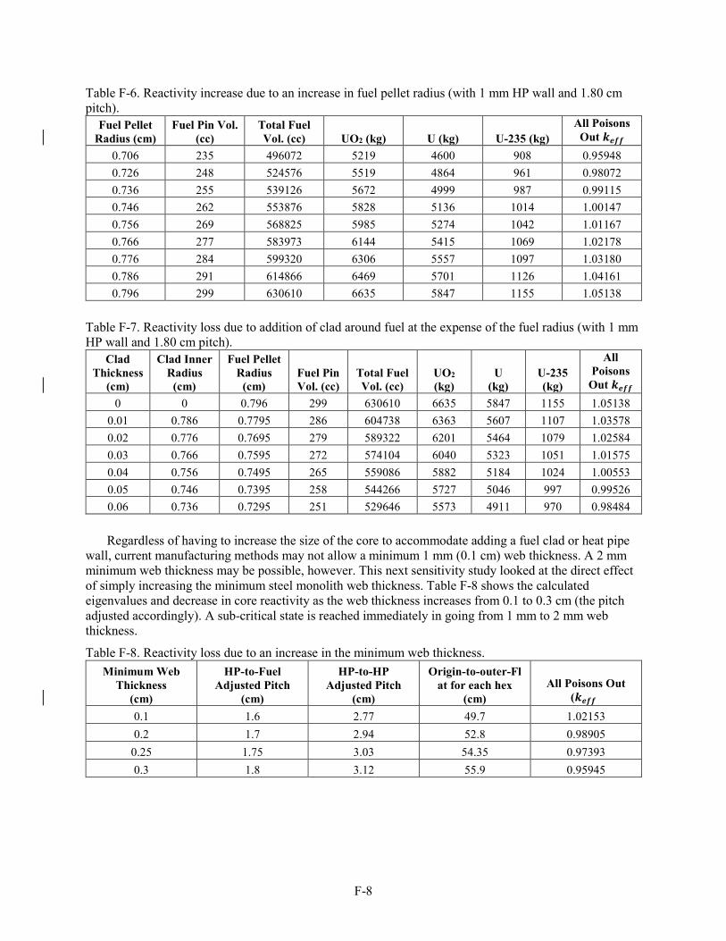
F-8
Table F-6. Reactivity increase due to an increase in fuel pellet radius (with 1 mm HP wall and 1.80 cm pitch).
Fuel Pellet Radius (cm)
Fuel Pin Vol. (cc)
Total Fuel Vol. (cc) UO2 (kg) U (kg) U-235 (kg)
All Poisons Out 𝒌𝒌𝒆𝒆𝒆𝒆𝒆𝒆
0.706 235 496072 5219 4600 908 0.95948 0.726 248 524576 5519 4864 961 0.98072 0.736 255 539126 5672 4999 987 0.99115 0.746 262 553876 5828 5136 1014 1.00147 0.756 269 568825 5985 5274 1042 1.01167 0.766 277 583973 6144 5415 1069 1.02178 0.776 284 599320 6306 5557 1097 1.03180 0.786 291 614866 6469 5701 1126 1.04161 0.796 299 630610 6635 5847 1155 1.05138
Table F-7. Reactivity loss due to addition of clad around fuel at the expense of the fuel radius (with 1 mm HP wall and 1.80 cm pitch).
Clad Thickness
(cm)
Clad Inner Radius
(cm)
Fuel Pellet Radius
(cm) Fuel Pin Vol. (cc)
Total Fuel Vol. (cc)
UO2 (kg)
U (kg)
U-235 (kg)
All Poisons
Out 𝒌𝒌𝒆𝒆𝒆𝒆𝒆𝒆 0 0 0.796 299 630610 6635 5847 1155 1.05138
0.01 0.786 0.7795 286 604738 6363 5607 1107 1.03578 0.02 0.776 0.7695 279 589322 6201 5464 1079 1.02584 0.03 0.766 0.7595 272 574104 6040 5323 1051 1.01575 0.04 0.756 0.7495 265 559086 5882 5184 1024 1.00553 0.05 0.746 0.7395 258 544266 5727 5046 997 0.99526 0.06 0.736 0.7295 251 529646 5573 4911 970 0.98484
Regardless of having to increase the size of the core to accommodate adding a fuel clad or heat pipe
wall, current manufacturing methods may not allow a minimum 1 mm (0.1 cm) web thickness. A 2 mm minimum web thickness may be possible, however. This next sensitivity study looked at the direct effect of simply increasing the minimum steel monolith web thickness. Table F-8 shows the calculated eigenvalues and decrease in core reactivity as the web thickness increases from 0.1 to 0.3 cm (the pitch adjusted accordingly). A sub-critical state is reached immediately in going from 1 mm to 2 mm web thickness.
Table F-8. Reactivity loss due to an increase in the minimum web thickness. Minimum Web
Thickness (cm)
HP-to-Fuel Adjusted Pitch
(cm)
HP-to-HP Adjusted Pitch
(cm)
Origin-to-outer-Flat for each hex
(cm) All Poisons Out
(𝒌𝒌𝒆𝒆𝒆𝒆𝒆𝒆) 0.1 1.6 2.77 49.7 1.02153 0.2 1.7 2.94 52.8 0.98905
0.25 1.75 3.03 54.35 0.97393 0.3 1.8 3.12 55.9 0.95945

F-9
A further study was done to see how much reactivity could be gained by both increasing the size of the reflector and changing the reflector material, while maintaining a 2 mm (0.2 cm) minimum web thickness and a 1.8 cm pitch. Initially, the CDs were kept in their original positions in the side reflector (distance between the reflector inner radius and CD centers was constant) while the reflector radial dimension was increased. Regardless of reflector material, even an infinite reflector in this situation only boosts the reactivity by around 100 pcm since the B4C arcs would absorb the vast majority of reflected neutrons heading toward the reactor core. However, if the distance between the center of the CDs and the reflector outer radius is constant, then increasing the reflector radius substantially increases the reactivity. These results are shown in Table F-9 for a few different materials, and it is clear that beryllium oxide offers the most increase in reactivity. However, the worth of the CDs also drops considerably as they are pushed further from the core.
Table F-9. Reactivity increase due to an increase in reflector radius (0.2 cm web and 1.8 cm pitch).
Reflector Outer Radius (cm)
Reflector Material Al2O3 BeO Be (metal) Stainless Steel
80.95 0.98905 0.99975 0.99789 0.97721 82.50 0.99325 1.00840 1.00572 0.9764 85.00 1.00082 1.02226 1.01873 0.97628 87.50 1.00731 1.03553 1.03145 0.97708 90.00 1.01282 1.0477 1.04322 0.97804 92.50 1.01731 1.05866 1.05382 0.9791 95.00 1.02097 1.06844 1.06306 0.9801 97.50 1.02377 1.07699 1.07104 0.98097 100.00 1.02592 1.08444 1.07783 0.9817 102.50 1.02754 1.0909 1.08337 0.98222 105.00 1.02873 1.0964 1.08800 0.98266
Radiation damage to the ferritic steel monolith was calculated in order to determine if it was a
concern. Two factors—fast reactor neutron spectrum and a relatively long 5-year burnup–prompted a concern for potential radiation damage; however, this concern was mitigated by the fact that the LANL core design has a relatively low core power density and corresponding low fast fluxes in the core. Table F-10 gives the calculated axial-average radiation damage, or “displacements per atom,” to the steel monolith as a function of core region. The radiation damage is given as a range, where the range covers the radial range of monolith MCNP cells from the inner-to-outer core sector flats. The monolith steel was assumed to be composed of 68% iron (Fe), 14% nickel (Ni), and 18% chromium (Cr). Radiation damage cross sections for these three major steel components were used in the calculation. The highest radiation damage is course for the in-core steel monolith, ranging from 0.86–1.90 dpa (displacements per atom). In order to get the local maximum damage, these Table F-10 values need to be multiplied by a factor of approximately 1.4 to account for the cosine shape of the core axial flux profiles. Hence, the maximum local radiation damage to the steel monolith is approximately 2.66 dpa. Radiation damage to the steel monolith is relatively small but will still need to be considered in the material property studies.
Table F-10. Average radiation damage (dpa) to steel monolith after 5 years irradiation. Core Region Radiation Damage (dpa)
Upper reflector 0.12–0.37 Reactor core 0.86–1.90
Lower reflector 0.13–0.44 Gas plenum 0.03–0.20

F-10
A reactor core depletion calculation was performed on the LANL reactor core using the beginning-of-life reactor parameters listed in Table 1 above. The depletion analysis assumed continuous reactor operation at 5 MW thermal power level for a 5-year period. The beginning-of-life (BOL) reactor core contains approximately 5.22 MT UO2, 4.6 MT U, and 0.91 MT U-235. For a 5 MW thermal power level, the U-235 depletion rate per day is approximately 6.25 g/day, or 11.4 kg/5yrs, or 1.26% U-235 depletion over 5-years. This represents approximately 9.1 kg of heavy metal fission over 5 years, or 0.2% of all the initial heavy metal. The fuel burnup at the end of 5 years is <2,000 MWD/MTU. The depletion calculation showed the core could easily achieve the 5-year operating cycle length and still have sufficient reactivity to continue operation if desired. The low fuel burnup after 5 years, however, indicates very low uranium utilization and end-of-life uranium enrichment up near 19.5%.
The INL MCNP physics models were also used to calculate BOL axial and radial heat rates for the UO2 fuel pins, liquid metal potassium in the heat pipes, and the in-core steel monolith. In addition, heat rates were calculated for the upper reflector, lower reflector, and the gas plenum. These calculated heat rates were used as input in the thermal analysis model to predict fuel and monolith temperature and stress/strain as a function of position throughout the reactor core and reflectors.
In-core activation of the potassium liquid and vapor in the heat pipes has been evaluated. The activation analysis assumed a 5-year continuous reactor operation at 5 MW thermal. A single heat pipe loaded with 100 grams of potassium was activated for the 5-year period. At the end of the 5-year period (maximum activation), the major radioisotopes identified were as follows: 0.255 curies (Ci) of Ar-39 with a 269-year half-life (β- decay only, no gamma emission), 0.213 Ci K-42 with a half-life of 12.36 hours (β- decay and gamma emission), 54.6 µCi Cl-36 with a half-life of 301,000 years (β- and β+
decay/emitter). Activation of the potassium does occur and builds up with exposure. In the event of a heat pipe breach (weld or monolith web failure), activated potassium vapor could be emitted from the heat pipes.
Neutron and gamma radiation streaming out of the core through the heat pipes is a potential concern for dose to personnel in the vicinity of the reactor system. In addition, the specific streaming of neutrons could activate ex-core structures as well. These radiation transport and activation analyses have not yet been performed by INL. Hence, the impact of radiation streaming through the heat pipes is not known.
NEUTRONICS SUMMARY This appendix presents highlights from a preliminary INL neutronic analysis of the LANL Special
Purpose Reactor design. The calculated beginning-of-life core excess reactivity is sufficient to achieve the 5-year operating cycle and is readily controllable with the 12 rotatable control drums. Two additional safety control rods could be added to provide independent shutdown capability as well. The calculated reactivity feedbacks from the UO2 Doppler-broadening, UO2 thermal expansion, and steel monolith thermal expansion is all negative and of sufficient magnitude to provide good controllability.
The reactor is a tightly coupled, fast reactor with a relatively low beginning-of-life enrichment for a fast reactor. Use of an alumina reflector is unusual but is needed to boost core reactivity. The core reactivity is very sensitive to fuel pellet diameter and steel monolith minimum web thickness. In fact, the core reactivity is so sensitive to web thickness that it cannot be increased to a level where a manufacturer could drill the required fuel and heat pipe channels without causing the reactor to go sub-critical. This sensitivity also prevents the introduction of a fuel cladding or dedicated heat pipe wall in-core by pushing the reactor core further into sub-critical territory. Additional reactivity can of course be increased if a larger core size can be tolerated. Larger core size translates into more weight. INL is not aware of the design requirements LANL has implemented for the reactor size and weight limits.

F-11
Core criticality may also be an issue. The relatively small initial beginning-of-life excess reactivity may not be sufficient. Uncertainties in the U-235 capture and fission cross sections in the fast spectrum range are estimated to be on the order of the calculated available excess reactivity. Plus, there are no available fast critical assemblies that employ an alumina reflector or structure. Construction of a prototypical core or critical assembly would need to be constructed to demonstrate both core criticality and magnitude of the excess reactivity. In addition, the physics codes would need to demonstrate that they can calculate the measured critical state and excess reactivity.
Flooding combined with heat pipe breaches could result in super-criticality, although this is an extremely low probability event.
The substantial UO2 beginning-of-life inventory in the core combined with the low power density allow the reactor to operate easily for the 5-year requirement. The tiny burnup of the fuel after 5 years does not substantially change the enrichment by end-of-life. The overall uranium utilization is poor.
The results of the INL neutronic analyses by-in-large confirm much of the LANL neutronic published results.
REFERENCES 1. Monte Carlo N-Particle Transport Code System Including MCNP6.1, MCNP5-1.60, MCNPX-2.7.0
and Data Libraries. Initial MCNP6 Release Overview – MCNP6 version 1.0. Los Alamos National Laboratory, Los Alamos, New Mexico, August 2013.
2. P. McClure, D. Poston, D.V. Rao and R. Reid, Design of Megawatt Power Level Heat Pipe Reactors, LA-UR-15-28840 (Los Alamos, NM: LANL, 2015).

F-12

G-1
Appendix G
Special Purpose Reactor Plant Assessment Report

G-2

G-3
Appendix G
Special Purpose Reactor Plant Assessment Report
G-1. THE POWER CONVERSION UNIT
G-1.1 Introduction
The Special Purpose Reactor is a small reactor that generates 5 MW(t) heat and has the potential to produce 2 MW(e) power. The reactor consists of a stainless steel monolith within which holes are bored to contain fuel rods and heat pipes. The heat pipes are used to cool the reactor using potassium as the working fluid. The boiling side of the heat pipe captures the heat from the fuel rods. The condensing side of the heat pipe transfers heat to air blown across the pipes. The heated air is expanded in a turbine to produce power using an air Brayton open cycle.
This report will describe the development of a process model of the cycle and present the results and findings from this model.
G-1.2 Model Development
G-1.2.1 Thermodynamic Cycle Considerations
Compressor Turbine
Air In
HighTemperature
Heat Exchanger
Air Out
Heat In
Figure G-1. Simple air Brayton power cycle.

G-4
The air Brayton cycle is a common power conversion system. The cycle is used to produce thrust in jet engines or to produce power such as natural gas turbines. The basic cycle compresses ambient air to an optimal pressure. The air is heated to a desired temperature using either a heat exchanger (as in the case of the Special Purpose Reactor) or a combustion chamber (as in the case of a natural gas turbine).b The high-pressure, high-temperature gas is expanded through a turbine, which in turn produces power (see Figure G-1).
Air In
CompressorStage 2
TurbineStage 1
High TemperatureHeat Exchanger
Heat In
CompressorStage 1
Intercooler
Heat Out
RecuperatingHeat Exchanger
TurbineStage 2
Reheater
Reheat
Air Out Figure G-2. Air Brayton cycle with compressor intercooling, heat recuperation and reheat.
A variety of enhancements may be used to improve the performance of the cycle (see Figure G-2). These include:
• Recuperating heat exchangers. These heat exchangers remove heat from the air exiting the turbine to preheat the air before it enters the high-temperature heat exchanger or the combustion chamber. By recuperating the heat, the source heat may be reduced for a given power production rate, better utilizing the heat produced.
• Reheat. Through the use of staged turbine expansion, as the air passes through each stage, the air may be reheated within the high temperature heat-exchanger or the combustion chamber before passing through the next stage of expansion. The reheated air produces more power from each turbine stage.
• Intercooling between compression stages. If the compression is separated into stages, the air exiting each stage may be cooled with the ambient, using heat exchangers called intercoolers. The intercoolers help reduce compression power, because the air is denser and, therefore, requires less power to compress the air.
These enhancements help improve the performance (more power output for less heat input) but require more capital cost.
bG.J Van Wylan and R.E. Sonntag, “Some Power and Refrigeration Cycles,” chap 7 in Fundamentals of Classical
Thermodynamics, 2nd ed. (Hoboken, NJ: John Wiley and Sons, Inc., 1973).

G-5
Air In
High TemperatureHeat Exchanger
Heat In
Compressor
RecuperatingHeat Exchanger
Turbine
Air Out
Figure G-3. Recuperated air Brayton cycle for the Special Purpose Reactor.
For the Special Purpose Reactor as specified for this work, reheat is not possible, and the compression ratio is rather small, which negates the need for intercooling; therefore, only heat recuperation was considered. This configuration is not capital intensive and should have a smaller footprint, making it ideal for use with Department of Defense applications. Figure G-3 shows the basic configuration for the power conversion unit (PCU) considered for the Special Purpose Reactor.
The thermal efficiency of the air Brayton cycle is a metric used to measure the performance. The efficiency is calculated by dividing the power produced by cycle by the heat into the cycle. The power produced is the summation of the turbine and the compressor power. Power into a thermodynamic system is negative and power out of a system is positive. The compression power is negative and will draw its power from the turbine. The turbine power remaining is the power produced by the cycle.
G-1.2.2 Process Models
Two process models were developed for integration with the Special Purpose Reactor, a simple air Brayton cycle and a recuperated air Brayton cycle. By modeling both power conversion cycles, one can see the improvement made by recuperating the heat.
The models were developed using Aspen Technology’s HYSYS process modeling software. HYSYS uses a large thermodynamic database and a selection of typical thermal and chemical process components such as heat exchangers, valves, pipes, compressors, pumps, columns, chemical reactors, tanks, and turbines. The software ensures a complete and accurate mass and energy balance of the integrated process.c
Both models can vary the ambient conditions such as temperature, pressure, and relative humidity. This allows simulations to be performed in a variety of regional conditions such as deserts, rainforests, or high elevations.
cAspen HYSYS, V8.6, © 1995–2014 Aspen Technology Inc., www.aspentech.com.

G-6
G-1.2.2.1 Assumptions. For the baseline development of the process models the following assumptions were made.
• The turbine and compressor isentropic efficiencies are both 90%.
• The pressure drops across the heat exchangers are 2% of the inlet pressures.
• The heat transferred from the heat pipes to the air is 5 MW(t).
• Ambient air conditions are:
- inlet air temperature is 25°C,
- inlet air pressure is 0.101325 MPa,
- outlet air pressure is 0.101325 MPa,
- and inlet relative humidity is 50%.
• The inlet temperature into the turbine is 675°C.
• The minimum temperature difference between the hot side and the cold side of the heat exchangers is 25°C.
The ambient conditions are fairly standard for analysis but can be changed to meet specific regional conditions. The heat from the reactor (heat transferred from the heat pipes) sets the size of the system. The pressure drop across the heat exchangers is set to 2% of the inlet, instead of a constant pressure drop to allow the model to run optimizations cases without crashing due to pressure drops that create outlet pressures that are below zero. The isentropic efficiencies were set to simulate better performing but realistic turbines and compressors. The temperature difference between the cold side and the hot side across the heat exchangers (recuperating heat exchanger) was set to be conservative. This allows for a smaller heat exchanger; however, recuperating heat exchangers have been designed to have minimum temperature differences as low as 5.6°C at the cost of building a larger heat exchanger.d
G-1.2.2.2 Aspen HYSYS Models. Typical conditions based on the Special Purpose Reactor for the simple and the heat recuperated air Brayton cycles are shown in Figure G-4 and Figure G-5. More discussion about these conditions can be found in the results section.
Figure G-4. Aspen HYSYS model of simple air Brayton cycle.
dS.C. Stultz and J.B. Kitto, Steam: Its Generation and Use, 41st ed. (Charlotte, NC: The Babcock & Wilcox Company, 2005).

G-7
Figure G-5. Aspen HYSYS model of heat recuperated air Brayton cycle.
G-1.3 Results
The following parametric studies were performed with the process models to analyze the performance of the cycles.
• The pressure ratio of the compressor was varied from 1 to 25 for both cycles, keeping all other inputs constant per the above assumptions.
• The pressure ratio of the compressor and the turbine inlet temperature were varied for the heat recuperated air Brayton cycle with all other inputs constant per the assumptions.
• The isentropic efficiency of the turbine was varied with all other inputs per the assumptions for the heat recuperated air Brayton cycle.
• The isentropic efficiency of the compressor was varied with all other inputs per assumptions for the heat recuperated air Brayton cycle.
G-1.3.1 Varying Compressor Pressure Ratio for Simple and Heat Recuperated Air Brayton Cycles
The pressure ratio of the compressor was varied from 1 to 25 for both cycles. The results of this study are shown in Figure G-6 and Figure G-7. With respect to the simple cycle, the turbine power increases slightly more than the compressor power at lower pressure ratios; however, at pressure ratios greater than 11, the compressor power increases more. The total power out and the thermal efficiency reach optimal values of 1.47 MW(e) and 29.4% at a pressure ratio of 11.

G-8
Figure G-6. Power and thermal efficiency as a function of the compressor pressure ratio for the simple air Brayton cycle.
Figure G-7. Power and thermal efficiency as a function of the compressor pressure ratio for the heat recuperated air Brayton cycle.
0%
5%
10%
15%
20%
25%
30%
35%
0
2
4
6
8
10
12
14
0 5 10 15 20 25
Ther
mal
Effi
cien
cy
Pow
er (M
We)
Pressure Ratio of Compressor
Compressor PowerTurbine PowerPower OutThermal Efficiency
0%
5%
10%
15%
20%
25%
30%
35%
40%
45%
50%
-
0.50
1.00
1.50
2.00
2.50
3.00
3.50
4.00
4.50
5.00
1 2 3 4 5 6 7 8 9
Ther
mal
Effi
cien
cy
Pow
er (M
We)
Pressure Ratio of Compressor
Compressor PowerTurbine PowerPower OutThermal Efficiency

G-9
For the heat-recuperated cycle, the turbine power increases rapidly at compressor pressure ratios less than 2.5 but levels off at pressure ratios above 2.5. The compressor power increases at a nearly constant rate for the pressure ratio range shown. This results in a rapid increase in power out as the pressure ratio increases from 1 to 2.25, but then it decreases for higher pressure ratios. The power out and the thermal efficiency reach optimal values of 2.02 MW(e) and 40.3% at a pressure ratio of 2.48.
Figure G-4, Figure G-5, and Table G-1 show the conditions of the cycles at their optimum. The heat recuperated cycle has a pressure ratio that is 22% of the simple cycle and the thermal efficiency is much higher. The power of the recuperated cycle is 37% higher and the air exhaust temperature is 130°C less than the simple air cycle. The lower pressure ratio of the recuperated cycle aids in reducing the compression power. The lower air exhaust temperature indicates better utilization of the heat into the cycle. Although the addition of a recuperating heat exchanger could increase the capital cost of the cycle, the much higher performance justifies the cost.
Table G-1. Comparison of performance parameters between the simple and heat recuperated air Brayton cycles.
Simple Air Brayton Cycle Heat Recuperated Air Brayton Cycle
Pressure Ratio 11.0 2.48 Thermal Efficiency 29.4% 40.3% Power Out (MWe) 1.47 2.02 Air Exhaust Temperature (°C) 279.1 148.5
G-1.3.2 Varying Compressor Pressure Ratio and Turbine Inlet Temperature for
the Heat Recuperated Air Brayton Cycle
The compressor pressure ratio and the turbine inlet temperature were varied from 1 to 10 and 600°C and 872°C, respectively (see Figure G-8). The latter turbine inlet temperature is based on future designs for the Special Purpose Reactor.e There is a direct correlation between the power out and the thermal efficiency because the heat input is constant. Both increase rapidly for pressure ratios less than 2.5 but then decrease gradually for the higher pressure ratios. Even at a 600°C turbine inlet temperature, the optimal thermal efficiency is 36%. The plot shows that the heat-recuperated cycle performs well over a wide range of turbine inlet temperatures.
With respect to Figure G-8, the plot was generated assuming isentropic efficiencies of 90% for both the compressor and the turbine. The primary purpose in varying the pressure ratio was to find the optimal design conditions. For a given design, varying the pressure ratio from design will result in lowering the isentropic efficiencies. Turbine and compressor manufacturers provide maps to determine the performance of their equipment at off-design conditions. For that reason, Figure G-8 should not be used to estimate the performance of the cycle for pressure ratios beyond the optimal.
The air exhaust temperature was also plotted as a function of the compressor pressure ratio and the turbine inlet temperature (see Figure G-9). Although only one line is apparent, the various turbine inlet temperature lines are plotted. They lie on top of each other, which indicate that the turbine inlet temperature has no effect on the air exhaust temperature.
eD.V. Rao (Los Alamos National Laboratory), personal communication, August 25, 2016. The case is for a Moly-UN reactor.

G-10
Figure G-8. Power out and thermal efficiency as a function of the compressor pressure ratio and the turbine inlet temperature for the heat- recuperated air Brayton cycle.
Figure G-9. Air exhaust temperature as a function of the compressor pressure ratio and the turbine inlet temperature for the heat recuperated air Brayton cycle.
1.00
1.50
2.00
2.50
20%
25%
30%
35%
40%
45%
50%
0 1 2 3 4 5 6 7 8 9 10
Pow
er O
ut (M
We)
Ther
mal
Effi
cien
cy
Pressure Ratio of Compressor
600ºC625ºC650ºC675ºC700ºC725ºC872ºCSeries8
Air Temperatureinto Turbine
50
100
150
200
250
300
350
1 2 3 4 5 6 7 8 9 10
Air E
xhau
st T
empe
rtur
e ºC
Pressure Ratio of Compressor
600ºC625ºC650ºC675ºC700ºC725ºC872ºCCompressor Outlet Temperature
Air Temperatureinto Turbine

G-11
This can be explained by analyzing the recuperating heat exchanger. The heat exchanger is an air-to-air heat exchanger with a minimum temperature difference of 25°C between the hot fluid and the cold fluid. Therefore, the air exhaust temperature is around 25°C above the compressor outlet temperature. The air exhaust temperature is only affected by the compressor outlet temperature, which, in turn, is affected only by the pressure ratio and not the turbine inlet temperature.
G-1.3.3 Varying Compressor and Turbine Isentropic Efficiencies
Figure G-10. The thermal efficiency as a function of the compressor and turbine isentropic efficiencies.
The compressor efficiency was varied from 60 to 95% while keeping the turbine efficiency at 75%. Another parametric analysis varied the turbine efficiency from 60 to 96% while keeping the compressor efficiency at 75%. The results from these studies are show in Figure G-10. The thermal efficiency of the cycle tends to be slightly higher at higher turbine efficiencies than compressor efficiencies. The compressor has slightly higher thermal efficiencies than the turbine for lower component efficiencies.
0%
5%
10%
15%
20%
25%
30%
35%
40%
60% 65% 70% 75% 80% 85% 90% 95% 100%
Ther
mal
Effi
cien
cy
Component Isentropic Efficiency
Comp Eff @ Turb Eff = 75%
Turb Eff @ Comp Eff = 75%

G-12
Figure G-11. Optimal heat recuperated air Brayton cycle with compressor and turbine isentropic efficiencies of 85%.
An optimal case was run with both the compressor and the turbine isentropic efficiencies set at 85% (see Figure G-11). The thermal efficiency dropped to 34.4%, compared to 40.3% from the 90% isentropic case. The isentropic efficiency has a strong impact on the thermal efficiency of the cycle. To obtain higher thermal efficiencies, it will be important to develop turbines and compressors that have high isentropic efficiencies (>85%).
G-1.4 Commercial Units
A cursory search was made to find commercial gas turbines that are of the same order (power level) as that of the Special Purpose Reactor. Three vendors were investigated: GE,f Siemens,g and Kawasakih (see Table G-2). The minimum-sized product from each vendor is shown. GE does not offer anything less than 20 MW(e); however, both Siemens and Kawasaki have units less than 5 MW(e). The efficiencies shown in Table G-2 are based on simple cycles. They are also based on natural gas, which provides turbine inlet temperatures >1000°C.
f GE Power, Powering the World 2016, accessed January 5, 2017, https://powergen.gepower.com/content/dam/gepower-
pgdp/global/en_US/documents/product/2016-gas-power-systems-products-catalog.pdf. g Siemens, We Power the World with Innovative Gas Turbines: Siemens Gas Turbine Portfolio, accessed January 5, 2017,
http://www.energy.siemens.com/ru/pool/hq/power-generation/gas-turbines/downloads/gas-turbines-siemens.pdf. hKawasaki, “Kawasaki Gas Turbine Generator Sets: Green Gas Turbines,” accessed January 5, 2017,
https://global.kawasaki.com/en/energy/pdf/Green_Brochure.pdf.

G-13
Table G-2. Performance specifications of various commercial natural gas turbines.
Manufacturer Power Output
(MWe) Thermal Efficiency
(Simple Cycle) GE LM2500 23-34 >38% Siemens Industrial 501-KB5S 4 30.6% Kawasaki M1A-13A 1.49 24.2
G-1.5 Conclusions
The following conclusions may be made about the air Brayton cycle.
• The cycle has a long legacy of industrial development and commercialization, which makes it ideal for rapid deployment.
• Expected thermal efficiencies for cycle range from 25 to 40%.
• A heat-recuperated cycle greatly improves the thermal efficiency of the cycle.
• Units designed for the Special Purpose reactor will need to have isentropic efficiencies that are on the order of 85% or greater.
• Commercial units of comparable size are available.