special report - defense technical information · pdf filespecial report accuracy control...
TRANSCRIPT

TECHNOLOGY
TRANSFER PROGRAM (TTP)
SPECIAL REPORTACCURACY CONTROL PLANNING
FOR HULL CONSTRUCTION
Prepared By:
Levi ngston Shipbuilding Companyin cooperation with:IHI Marine Technology Inc. March 15, 1980

Report Documentation Page Form ApprovedOMB No. 0704-0188
Public reporting burden for the collection of information is estimated to average 1 hour per response, including the time for reviewing instructions, searching existing data sources, gathering andmaintaining the data needed, and completing and reviewing the collection of information. Send comments regarding this burden estimate or any other aspect of this collection of information,including suggestions for reducing this burden, to Washington Headquarters Services, Directorate for Information Operations and Reports, 1215 Jefferson Davis Highway, Suite 1204, ArlingtonVA 22202-4302. Respondents should be aware that notwithstanding any other provision of law, no person shall be subject to a penalty for failing to comply with a collection of information if itdoes not display a currently valid OMB control number.
1. REPORT DATE 15 MAR 1980
2. REPORT TYPE N/A
3. DATES COVERED -
4. TITLE AND SUBTITLE Technology Transfer Program (TTP) Special Report Accuracy ControlPlanning for Hull Construction
5a. CONTRACT NUMBER
5b. GRANT NUMBER
5c. PROGRAM ELEMENT NUMBER
6. AUTHOR(S) 5d. PROJECT NUMBER
5e. TASK NUMBER
5f. WORK UNIT NUMBER
7. PERFORMING ORGANIZATION NAME(S) AND ADDRESS(ES) Naval Surface Warfare Center CD Code 2230 - Design Integration ToolsBuilding 192 Room 128-9500 MacArthur Blvd Bethesda, MD 20817-5700
8. PERFORMING ORGANIZATIONREPORT NUMBER
9. SPONSORING/MONITORING AGENCY NAME(S) AND ADDRESS(ES) 10. SPONSOR/MONITOR’S ACRONYM(S)
11. SPONSOR/MONITOR’S REPORT NUMBER(S)
12. DISTRIBUTION/AVAILABILITY STATEMENT Approved for public release, distribution unlimited
13. SUPPLEMENTARY NOTES
14. ABSTRACT
15. SUBJECT TERMS
16. SECURITY CLASSIFICATION OF: 17. LIMITATION OF ABSTRACT
SAR
18. NUMBEROF PAGES
61
19a. NAME OFRESPONSIBLE PERSON
a. REPORT unclassified
b. ABSTRACT unclassified
c. THIS PAGE unclassified
Standard Form 298 (Rev. 8-98) Prescribed by ANSI Std Z39-18

PREFACE
This report is one of a series of detailed reports emanating from
the Shipbuilding Technology Transfer Program performed by Livingston
Shipbuilding Company under a contract with the U.S. Maritime Adminis-
tration.
This report augments the Livingston Final Report on Quality Assur-
ance, Number 2123-5.1-4-1, dated 3 March, 1980, with details concerning
the planning functions carried out by Accuracy Control groups for hull
construction within the shipyards of Ishikawajima-Harima Heavy Indus-
tries (IHI) of Japan.
In order to
Accuracy Control
should be made.
place the material contained herein within the overall
system reference to the above mentioned Final Report
i

TABLE OF CONTENTS
SECTION PARAGRAPH TITLE
1
2
2.1
2.2
2.3
2.4
2.5
2.6
3
3.1
3.2
3.2.1
3.2.2
3.2.3 .
INTRODUCTION
ACCURACY CONTROL OVERVIEW
PLANNING IN ’DESIGN
General
Hull Blocking Plan
Erection Sequence
Block Assembly Planning
Assembly Specification Plans
Working Instruction Plans
VITAL DIMENSIONS & POINTS OFACCURACY
General
Erection Stage Planning ofPoints
Hold Sections
Curved Sections
Stern Sections
3.3 Assembly Stage Planning ofPoints
3.3.1 Flat Unit Assemblies
3.3.2 Curved Unit Assemblies
3.4 Fabrication Stage PlanningPoints
Vital
Vital
of Vital
PAGE NO.
vi
1--1
2-1
2-1
2-3
2-5
2-6
2-6
2-12
3-1
3-1
3-3
3-3
3-6
3-7
3-8
3 - 8
3-9
3-11
ii
(Con’t)TABLE OF CONTENTS
SECTION PARAGRAPH TITLE
4
4.1
4.2
4.3
4.4
5.1
5.2
5.3
5.4
PLANNING FOR ADDITIONAL MATERIAL
General
Preliminary Planning
Detail Planning
Added Material Planning
ACCURACY CONTROL BASE LINES
General
Check Line for Cutting
Check Line for Shaping
Base Lines for Maintaining Accuracyin the Relationship of Materials
TOLERANCE STANDARDS
PAGE NO.
4-1
4-1
4-3
4-5
4-7
5-1
5-1
5-1
5-3
5-4
6-1
7-1CONCLUSIONS
.111

FIGURENO.
2-1
2-2
2-3
2-4
2-5
2-6
2-7
3-1
3-2
3-3
3-4
3-5
3-6
4-1
4-2
LIST OF ILLUSTRATIONS
TITLE
Typical Planning Steps
Hull Block Planning
Block Assembly Plan (Example)
Preliminary Assembly Specification Plan
Assembly Specification Plan
Detailed Assembly Specification Plan
Working Instruction Plans
Vital Dimensions & Points of Accuracy
Hold Sections
Typical Curved Unit
Stern Section Vital Points
Flat Panel Assembly Vital Points
Curved Unit Assemblies
Scheme of Added Material
Added Material Preliminary Planning
PAGE NO.
2-2
2-5
2-7
2-9
2-10
2-11
2-13
3-2
3-4
3-6
3-7
3-10
3-12
4--2
4-3
.
iv

FIGURENO.
4-3
4-4
4-5
4-6
5-1
5-2
5-3
5-4
5-5
6-1
6-2
LIST OF ILLUSTRATIONS
TITLE
Added Material Detailed Planning
Added Material Symbols
Additional Material Plan - Shell ExpansionAft Section
Added Material Calculation
Base Lines for Cutting
Base Lines for Shaping
Assembly Base Lines
Curved Unit Marking ’Tape
Assembly Base Line Marking(Curved Unit)
Tolerance Standards Regular Control(Examples )
Tolerance Standards Special Control(Examples)
--
PAGE NO.
4-6
4-7
4-8
4-9
5-2
5-3
5-5
5-6
5-7
6-3
6-4
v

INTRODUCTION
This report presents details of the Ishikawajima-Harima Heavy
Industries (IHI) Accuracy Control planning activities used in the IHI
shipyards in Japan. The report deals specifically with the planning
applicable to hull construction with only minimal reference to outfit-
ting.
This report is one of several emanating from the Shipbuilding
Technology Transfer Program performed by Livingston Shipbuilding Com-
pany under a cost sharing contract with the U.S. Maritime Administration.
The material contained herein was developed from the study of the
Accuracy Control system presently in operation in the IHI shipyards in
Japan. Information for this study was derived-from source documenta-
tion supplied by IHI, information
ing personnel assigned on-site at
vation by two teams of Livingston
various IHI shipyards in Japan.
obtained directly from IHI consult-
Levingston, and from personal obser-
personnel of actual operations at
Other reports pertinent to the
part of the Shipbuilding Technology
Livingston Final Report -
.Levingston Final Report -
subject of Accuracy Control and
Transfer Program are:
Quality Assurance System
Industrial Relations
This report consists of seven sections as follows:
Section 1 -
Section 2 -
Section 3 -
Section 4 -
Accuracy Control Overview
Planning In Design
Vital Dimensions & Points of Accuracy
Scheme of Added Material
vi

Section 5 -
Section 6 -
Section 7 -
Base Lines
Tolerance Standards
Conclusion
It should be noted that this report deals with Production Planning
entirely from the viewpoint of Accuracy Control. In reality, Production
Planning takes into consideration many more aspects of engineering
such as: maximum utilization of facilities and manpower, productivity,
safety improvement and so on. This is not intended to be a complete
description of the Production Planning process.
vii

SECTION 1
ACCURACY CONTROL OVERVIEW
Accuracy Control in IHI is the underlying concept of the entire
production system. The concept is simple in its definition but highly
involved and complex in application. The objectives of Accuracy Con-
trol are: to maintain the highest accuracy possible at each stage of
production of every fabricated piece, part, sub-assembly, assembly and
erected unit; to minimize the work at the erection stage; and to con-
tinuously improve the production process to yield the highest accuracy
in all products.
The Accuracy Control function comprises three elements: Planning;
Field Activity; and Data Analysis and Information Feedback. Each of
these activities is carried out by several .different groups located
in different departments: the Shipyard Design Department, the-Panel
Workshop, the Hull Workshop and the Fitting Workshop. These Accuracy
Control groups report to the managers or superintendents of their re-
spective
The
vance of
departments or workshops.
activities of these various groups are started well in ad-
the development of working drawings. Accuracy Control Plan-
ning is undertaken on the basis of preliminary (basic) design (which
is generated by the IHI Head Office in Tokyo) several months prior to
the start of fabrication. This planning effort i~olves participation
with the designers in determining the ship breakdown, the fabrication
sequence, the assembly sequence, and the erection sequence. Subse-
quently, Accuracy Control Planners develop: Vital Dimensions and
1-1

. -—. . . . . . . . . . . . . . — . . . . .
Points of Accuracy; the Scheme of Added Materials; Base Lines for loft-
ing and measuring; and” Tolerance Standards for the ship being planned.
Subsequent to the completion of the Accuracy Control Planning and -
to the start of fabrication, Accuracy Control Field Activities begin.
These activities consist of development of: check sheets for fabri-.
cated pieces, sub-assemblies, assemblies, and erected units; template
and plate layout requirements; methods for cutting and measurement of
plates; and fabrication methods. Actual field
taken on the manufactured pieces and assemblies
Control personnel and Quality Control personnel
check sheet requirements. Through this process
subsequent analysis and information feedback to
groups. .
measurements are ’then
by workers, Accuracy
in accordance with the
data are collected for
design or production
The data collected by Accuracy Control groups are analyzed to
determine causes of errors or material discrepancy (i.e. distortion,
warpage, twist, etc.) and resultant information is fed-back to the ap-
propriate organization for correction either in design or in the pro-
duction process responsible for the error or discrepancy.
Throughout this Accuracy Control process every attempt is made to
improve the production processes, methods and techniques. to yield
better, more accurate products at each production stage. This results
not only in improved quality but also in increased productivity
throughout the ship construction process.
1-2

SECTION 2
PLANNING IN DESIGN
2.1 GENERAL
Accuracy Control planning begins immediately upon completion of
the Basic Design (accomplished by the Design Department in the Head
Office of IHI in Tokyo). The Basic Design consists of: Unfaired Ship’s
Lines, Midship Section, Construction Profile, General Arrangement and
Machinery Arrangement drawings. On the basis of these plans the ship-
yard Design Department and the Accuracy Control group in the Design
Department undertake-the breakdown of the ship into “Blocks” or assem-.
bly units. This activity is called “Hull Block Planning” and consists
of dividing the ship into manageable units suitable for assembly and
erection.
Subsequent to this initial planning step “Block Assembly Planning”
is begun. This activity consists of a further breakdown of each “Block”
into its component pieces. As each block is disassembled on paper
Accuracy Control Engineers study and identify critical dimensions and
points for measuring the accuracy of each component part and the entire
assembly. .
Also during this process the erection sequence is determined
based on the Hull Block Planning and the assembly sequence is deter-
mined as a result of the Block Assembly Planning. As each assembly
is planned, f-abdication requirements for
bly are determined. Standard pieces are
cessing whereas peculiar or non-standard
.- . 2-1
each component and sub-assem-
identified for routine pro-
pieces are identified for

..—.— ————.
special Accuracy Control consideration, planning and measurement.
During this design planning phase Accuracy Control requirements
are developed for all purchased material and sub-contracted components.
These requirements are included in procurement specifications.
As the Block Assembly Planning is completed Assembly Specification
Plans are developed detailing methods of assembly and erection of each
unit. Workshop inputs provide details of welding processes, welding
edge beveling, extra lengths required for butt lines, and similar
information for inclusion in the Specification Plans.
TYPICAL PLANNING STEPS..-.----L\’.\xll’.Q<<Z< =Y<>ZC2C<CX*2*X.X Z22<I<ZI I
B4SIC DESIGN
HULLBLOCK
ERECTIONSEQUENCE
PLANNING&
v v
BLOCK PARTS LIST.FINISH DIMENSIONS.SUB-ASSEMBLY PLANASSEMBLY PLANS.ASSY,IIG SIZE LIST.
BLOCK ASSEMBLY WORKING LIFTING INSTRUCTION -ASSEMBLY -SPECIFICATION = INSTRUCTION PLAN.PLANNING PLANS PLANS
BLOCK ARRGT. PLAN.
vSHIPWRIGHT DIMEN.
ASSEMBLYSUPPORT BLOCKARRGT. PLAN
SEQUENCE WELDING INSTR. PLANSCAFE ARRGT- PLAN
FIGURE 2-1
.“
2-21

Detail Assembly Specification Plans are then reduced to Working
Instruction Plans which prescribe the processes, methods, and techni-
ques to be used for fabrication, sub-assembly, assembly and erection
of each piece, component and unit. Figure 2-1 depicts the development
of these various plans.
The following pages describe each of the above plans and the role
of Accuracy Control groups in their development.
2.2 HULL BLOCKING PLAN
The Hull Blocking Plan is the initial activity to be performed by
the shipyard Design Department. This activity comprises the breakdown
of the ship into individual units capable of being designed, produced,.
handled, and erected in the most efficient and least costly manner.
Because of the many years of experience with this method in IHI
the ship breakdown is a routine and systematized operation. Planning
generally centers initially around the mid-ship sections (i.e.-cargo
holds) since these sections represent the majority of ship units and
because of the repetitive nature of the mid-ship section units or
blocks . The bottom assemblies of”these cargo hold sections are also
the starting point for the development of accuracy control requirements
for curved (bottom) assemblies.
Forward and aft sections of the ship are necessarily treated in- ~
dividually and require a more indepth analysis to determine proper
division into assembly units.
Beginning with the bottom mid-ship section of the ship, assembly
units are defined using the following criteria:
1) First block (unit) to be laid in the building basin (this--
.
2-3

.
is generally the mid-ship section just forward of the engine room).
G : 2) Crane Capacity - The size of the blocks must be restricted to
the lifting capacity of the available cranes both in the assembly areas
and in the erection area.
~ 3) Assembly Areas - Block size is further limited by the size of
the assembly areas and facilities such as over-turning equipment,
transporters, cranes, etc. During over-turning and transportation the.
unit size must not be so great that deformation will occur during lift-
ing or movement.
4) Work Flow - Block size should be kept at an optimum size to
provide maximum work flow through the production work stations. Too
big a block would require a prolonged assembly time thus creating a
“bottle-neck” for following work.
5) Reduction of Erection Work - Block size and shape must be
capable of being easily erected and must be stable during joining.
Welding lengths must be minimal, especially difficult (overhead) welding.
6) On-block Outfitting - Assembly and outfitting schedules must
be taken into consideration in sizing blocks. Blocks of too large a
size or requiring an inordinate amount of on-block outfitting will
cause schedule delays, consume assembly area space, and delay follow-
ing work (which may also result in idle time in following work sta-
tions).
Using the above criteria the ship is divided into manageable blocks
which fit the facilities, equipment, manpower, and schedutes estab-
lished for ship construction. The overriding concern during this
. .
2-4
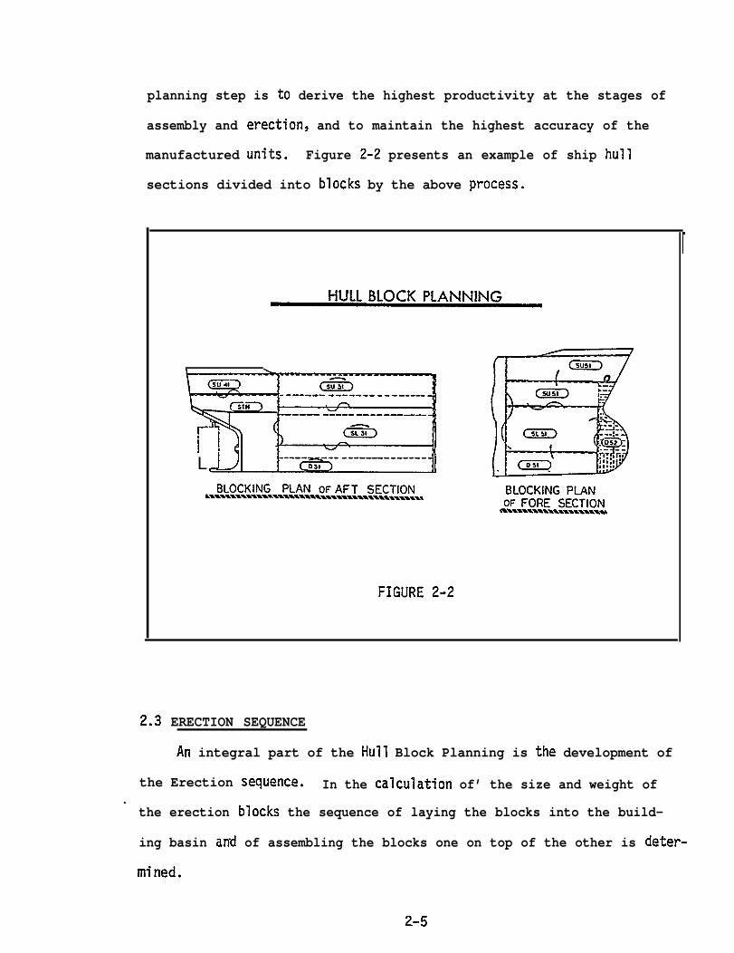
planning step is to derive the highest productivity at the stages of
assembly and erection, and to maintain the highest accuracy of the
manufactured units. Figure 2-2 presents an example of ship hull
sections divided into blocks by the above process.
------- ------- - - ----—
---— ----- —--___--
L
FIGURE 2-2
2.3 ERECTION SEQUENCE
An integral part of the Hull Block Planning is the development of
the Erection sequence. In the calculation of’ the size and weight of.
the erection blocks the sequence of laying the blocks into the build-
ing basin and of assembling the blocks one on top of the other is deter-
mined.
2-5

2.4
. . . —..—— . . ..—-—— .—. —.. .———.
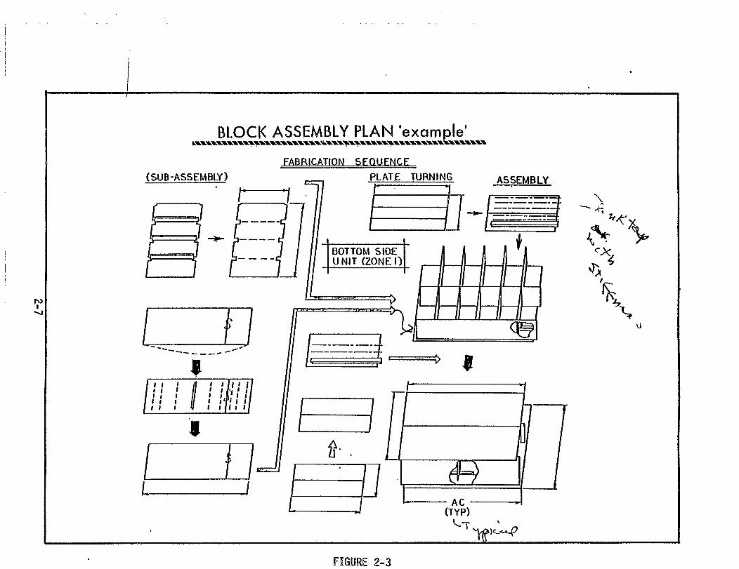
BLOCK ASSEMBLY PLANNING
After division of the ship into manageable blocks, typical common-
~haped blocks are analytically disassembled (on paper) in a progres-
sive breakdown from the entire unit to the component sub-assemblies.
and then to the. parts and pieces which constitute the sub-assemblies.
All unique blocks are broken down in this manner. Figure 2-3 shows a
typical example of such a breakdown.
These breakdowns serve several purposes in addition to showing
the basic assembly sequence of each block. A preliminary evaluation
of the assembly sequence yields details concerned with the necessary
facilities and processes required for the assembly, e.g. required fit-
ting jigs, probable welding processes, required assembly area size
and capacity. Further details are developed including: the classifi-
cation of sub-assemblies and assemblies; reference level and line;
length and types of welding-joints; welding edge-preparation require-
ments; and requirements for added material for adjusting seam and
butt lines.
the
and
All of this planning is considered “preliminary” information for
development of “detailed process planning” which is documented
disseminated as “Assembly Specification Plans” and “Working
Instruction Plans”.
2.5 ASSEMBLY SPECIFICATION PLANS
Based on the information developed during the. ’’preliminary pro-
cess planning”, formal
These plans detail the
assembly and erection.
personnel and accuracy
Assembly Specification Plans are developed.
methods to be followed during fabrication,
This planning is accomplished by engineering
control engineers in the Design Department and
2-6

.- -——__—— __ .- .—
in the various workshops.
Assembly Specification Plans are prepared for blocks of the fore
and aft sectio~s of the ship and for
sections. Evaluation of the assembly
assembly process lanes which must be
This evaluation concerns an in-depth
typical mid-ship (cargo holds)
sequence is made to determine the
used for curved versus flat blocks.
analysis of the processes through
which each of the piece parts and the sub-assemblies must flow in
order to be collected and assembled in the least possible time while
simultaneously achieving full utilization of manpower, facilities and
equipment. Throughout this planning, attention is given to the main-
tenance of accuracy at every production stage and sub-stage. Figure
2-4 is an example
stage.
The planning.
of the Assembly Specification Plan prepared at this
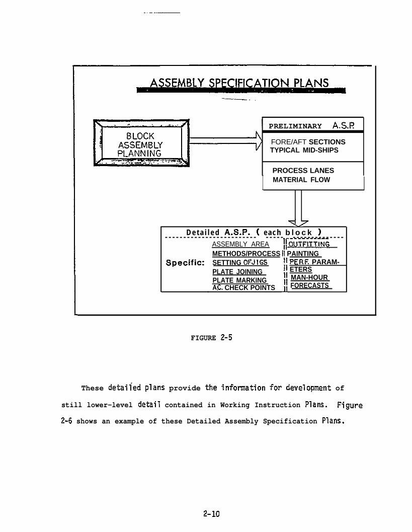
accomplished during the preparation of the Assembly. Specification Plans provides progressively more detailed information
for lower-level planning in the workshops. From this relatively broad
planning for assembly of blocks, Detailed Assembly Specification Plans
are
bly
developed for
procedures to
The
utilized
of jigs;
accuracy
detailed
each block. These
be utilized by the
plans specifically
plans provide more precise assem-
workshop personnel.
identify the assembly area to be
and the methods and processes to be used, such as: setti”ng
joining of plates; marking of plates; the sequence ofassembl~
check points to be measured at each step in the assembly pro-
cess; on-block outfitting; painting requirements; and performance con-
trol parameters (e.g. weld deposit per hour) and manhour forecasts
for each block.
2-8

. . . ..
—. .
PRELIMINARY A.SJ? iFORE/AFT SECTIONSTYPICAL MID-SHIPS
PROCESS LANES
I MATERIAL FLOW I
-D e t a i l e d A.S.P. ( each b l o c k )- - - - - - - - - - - - - - - - - - - - - - - - - - - - - - - - - - - - - - - - - - - -
ASSEMBLY AREA ~fOUTflTTINGMETHODS/PROCESS II PAINTING
Specific: SETTING OFJ ! GSPLATE JOININGPLATE MARKINGAC. CHECK POINTS
IIIIIIII
J.1
PERF. PARAM-ETERSMAN-HOURFORECASTS
FIGURE 2-5
These detailed plans provide the information for development of
still lower-level detail contained in Working Instruction Plans. Figure
2-6 shows an example of these Detailed Assembly Specification Plans.
2-1o

.
Detailed Aksy. Specification Plan
FIGURE 2-6
-. .————. -. . . —
.
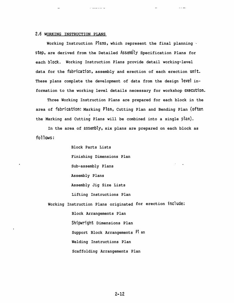
2.6 WORKING INSTRUCTION PLANS
Working Instruction Plans, which represent the final planning .
step, are derived from the Detailed Assembly Specification Plans for
each block. Working Instruction Plans provide detail working-level
data for the fabrication, assembly and erection of each erection unit.
These plans complete the development of data from the design level in-
formation to the working level details necessary for workshop execution.
Three Working Instruction Plans are prepared for each block in the
area of fabrication: Marking Plan, Cutting Plan and Bending Plan (often.
the Marking and Cutting Plans will be combined into a single plan).
In the area of assembly, six plans are prepared on each block as
follows:
Block Parts Lists
Finishing Dimensions Plan
Sub-assembly Plans
Assembly Plans
Assembly Jig Size Lists
Lifting Instructions Plan
Working Instruction Plans originated
Block Arrangements Plan
Shipwright Dimensions Plan
Support Block Arrangements
Welding Instructions Plan
. .
for erection include:
P1 an
Scaffolding Arrangements Plan
2-12
I Fabrication I .
MARKINGCUTT{NGBENDING
I Erection I
BLOCK ARRGT PLANSHIPWRIGHT DIMEN.P L A N~L~TNBLOCK ARRGT
WELDING INSTR PLAfSCAFFOLDING ARRGTPLAN
Assembly
● BLOCK PARTS LIST“FINISH DIMEN. PLAN-SUB -ASSEMBLY PLAN~ ASSEMBLY PLAN“ASSEMBLY JIG SIZELIST
- LIFTING INSTR.PLAh
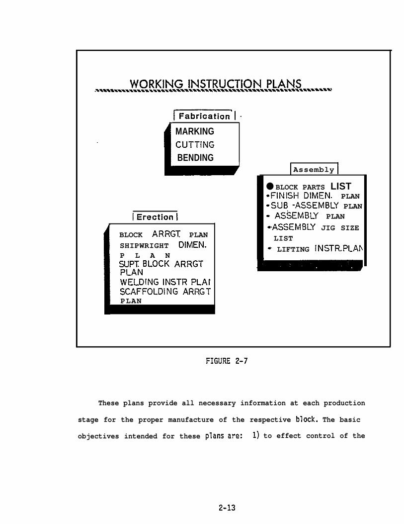
FIGURE 2-7
These plans provide all necessary information at each production
stage for the proper manufacture of the respective block. The basic
objectives intended for these plans are: 1) to effect control of the
2-13

.— . -
total workload and the products as the work progresses through the
various process lanes, sub-stages and stages of the production system;
2) to effect control of the great number of parts and ~ieces of
material as they flow through the production processes; and 3) to pro-
vide explicit instructions to all levels of personnel concerned with
the fabrication, assembly and erection of ship components.
Throughout this entire planning process Accuracy Control Engineers
prescribe necessary requirements to obtain the highest accuracy in
each fabricated part, sub-assembly and assembly.
.
2-14

SECTION 3
VITAL DIMENSIONS & POINTS OF ACCURACY.
3.1 GENERAL
Throughout the planning effort described in the preceding section,
Accuracy Control Engineers are developing detailed data concerning the
vital dimensions and points of measurement to assure that each piece
part, sub-assembly and assembly meets the highest accuracy standards
possible. c In addition, these engineers develop a plan (scheme) for
providing added material at each stage of production to assure that
errors can be corrected without re-work of the part and to provide for
neat cutting at the various sub-assembly, assembly or erection stages.
Accuracy Control Engineers also define the base lines which must be
used for sub-assembly and unit alignment to keep maximum accuracy
throughout the production, assembly and erection processes, and the
tolerance”standards to be observed by designers and production workers
during design, ship component manufacture and ship construction.
All of these data are developed simultaneously with the basic
* ship production planning and are included both in the planning data and
in the working “Yard Plans”
ment.
The de.velopmentof the
(drawi rigs) developed by the Design Depart-
planning data, described in this and the
preceding section, is an iterative process involving detail analysis
and evaluation of the requirements of each individual block. In order
to accomplish this planning the “Basic
together with several drawings created
Design” drawings are required
by the shipyard Design Department,
● ✎✍
3=-1

_-.. . . . .
such as: scaled body plans, shell expansions and certain structural
section plans. Also, the Blocking Plan, the Block Assembly Plan and
the Erection Sequence is required prior to the start of this subsequent
planning. \
ViTAL DIMENSIONS 8( POINTS OF ACCURACY
INPUT REQUIREMENTSBLOCKING PLAN ERECTION STAGEBLOCK ASSEMBLY PLAN \ERECTION SEQUENCE
HOLD SECTIONSCURVED SECTIONS
SCALED BODY PLANS STERN SECTIONS
SHELL EXPANSIONSTRUCTURE SECTION ASSEMBLY STAGE
STRAIGHT UNITCURVED UNITON FLAT PANELON CURVED PLATES
I FABRICATION STAGE IGIRDERSSIDE DECKSTANK DECKSHOLD FRAMES
l-- I
.2
FIGURE 3-1
3-2
.. ..
This section deals with the determination of Vital Dimensions
and Points of Accuracy. Subsequent sections detail the other Accuracy
Control planning responsibilities.o
The planning for the vital dimensions and points of measurement
concerns the three stages of Erection, Assembly and Fabrication in ‘that
order. All of the IHI planning proceeds from the end product (i.e. the- -——————— -
erected ship) back to the assembly and thence to the sub-assembly and
the piece parts. Therefore, the vital dimensions and vital points of
accuracy are first determined at the Erection stage.
3.2 ERECTION STAGE PLANNING OF VITAL POINTS
Accuracy of the total ship lines and of the blocks at erection is
the ultimate objective of the Accuracy Control system. The major sec-
tions of the ship designated for rigid control of accuracy are: the
hold sections; the curved sections; and the stern.
3.2.1 Hold Sections
These sections represent the majority of units in the ship and
are considered most critical from the standpoint of maintaining the. .
ship’s lines and accuracy. Critical points of measurement are con-
cerned with both the skin curvature of the hold bottom units and with .
the internal hold structure.
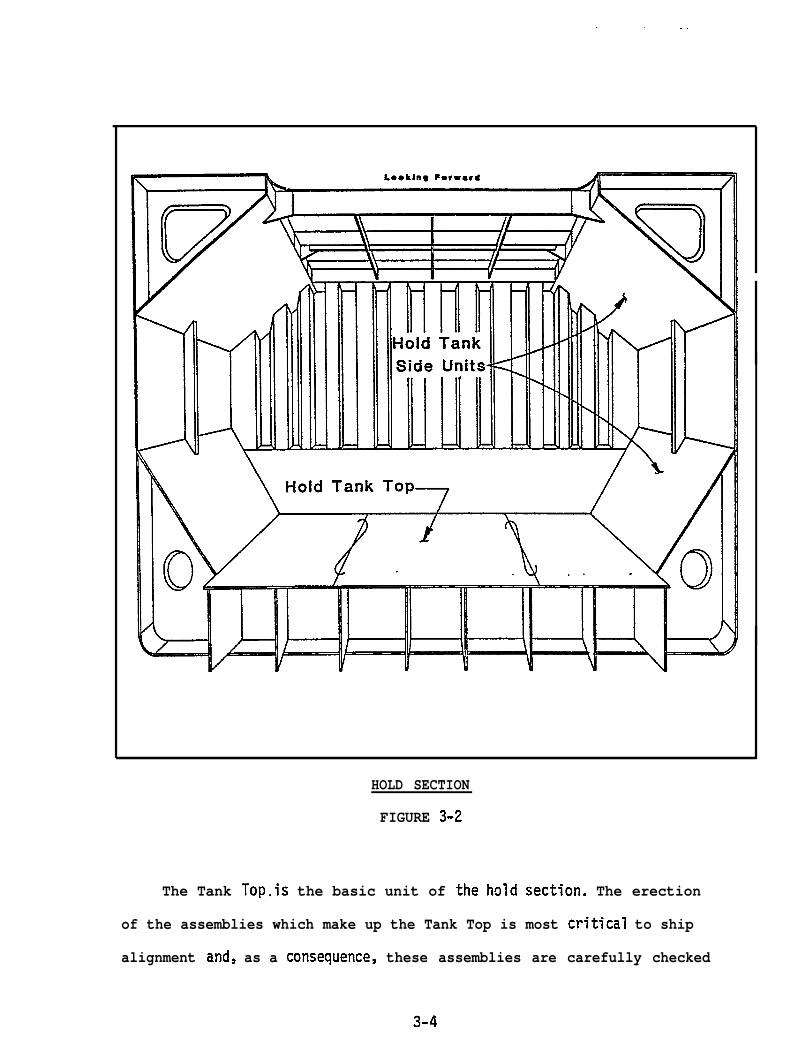
Vital points of
parts: the Tank Top
workable division of
hold sections are generally separated into two
and the Top Side Tank. This separation allows a
erection units and also provides a logical erec-
tion sequence to.Figure 3-2 shows
sections.
be developed for all of the mid-ship sections.
the configuration of these two parts of the hold
3-3
. . . -. . .
HOLD SECTION
FIGURE 3-2
The Tank Top.is the basic unit of the hold section. The erection
of the assemblies which make up the Tank Top is most critical to ship
alignment and, as a consequence, these assemblies are carefully checked
3-4
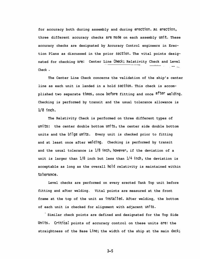
for accuracy both during assembly and during erection. At erection,
three different accuracy checks aremade on each assembly unit. These
accuracy checks are designated by Accuracy Control engineers in Erec-
tion Plans as discussed in the prior section. The vital points desig-
nated for checking are: Center Line Check; Relativity Check and Level. . —.— _. - . - -- —.Check .
The Center Line Check concerns the validation of the ship’s center
line as each unit is landed in a hold section. This check is accom-
plished two separate times, once before fitting and once after welding.
Checking is performed by transit and the usual tolerance allowance is
1/8 inch.
The Relativity Check is performed on three different types of
units: the center double bottom units, the center side double bottom
units and the bilge units. Every unit is checked prior to fitting
and at least once after weldihg. Checking is performed by transit
and the usual tolerance is 1/8 inch, however, if the deviation of a
unit is larger than 1/8 inch but less than 1/4 inch, the deviation is
acceptable as long as the overall hold relativity is maintained within
tolerance.
Level checks are performed on every erected Tank Top unit before
fitting and after welding. Vital points are measured at the front
frame at the top of the unit as installed. After welding, the bottom
of each unit is checked for alignment with adjacent units.
- Similar check points are defined and designated for the Top Side
Units. Critical points of accuracy control on these units are: the
straightness of the Base Line; the width of the ship at the main deck;
3-5

. — . . . - . . . . .———— —...—- ..- —.-—————. ._— _.. . . . . . . ——.
the height of the sh~p at the main deck; and the level of the main deck.
3.2.2 Curved Sections
Curved sections are also critical to the overall alignment of the
ship. In order to maintain accuracy of these sections, Accuracy Control
Engineers establish those points WhfCh are most amenable to measurement
and which will assure accuracy of alignment both vertically and hori-
zontally. Since these units have different widths at the top and the
bottom of the unit and since mating units must accurately match with
the top and bottom curve, it is imperative that these Curved sections
be carefully aligned upon erection. ‘Figure 3-3 shows a typical curved
unit and the vital points usually established for erection of such a
unit.
.
. -
V~ALPOINTS\*,L\\\\%*.\--”
Point A - For setting widthPoint B -For keeping straigkne~Point C - For setiing height &
checking width~Iowerelevotion
FIGURE 3-3
3-6
As shown in the figure, the width of the upper part of the unit and the
width of the bottom part of the unit are set individually as are the
height and the straightness of the unit. Accuracy Control Engineers
not only prepare the information on these vital dimensions and points
of measurement but also accomplish the actual measurement as these
units are erected.
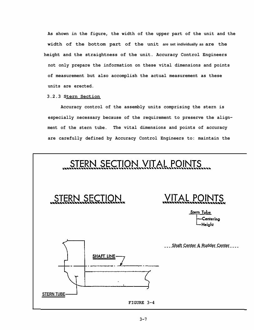
3.2.3 Stern Section
Accuracy control of the assembly units comprising the stern is
especially necessary because of the requirement to preserve the align-
ment of the stern tube. The vital dimensions and points of accuracy
are carefully defined by Accuracy Control Engineers to: maintain the
Shaft Center & Rudder Center- - - - - - - - - - - - - - - - - - - - - - - - - - - - - - -
STERN TUBE
FIGURE 3-4
3-7

accuracy of the center of the stern tube in both height and lateral
direction; maintain the relationship between the center of the stern
tube and the shaft line; and, maintain the relationship between the
shaft center and the rudder center. These relationships are extremely
difficult to maintain and require careful planning and measurement
during erection.
3.3 ASSEMBLY STAGE PLANNING OF VITAL POINTS
Accuracy planning of the vital dimensions and points of measure-
ment is particularly important in the assembly stage of ship construc-
tion. Accuracy control of the unit assemblies encompasses complete
assessment of every construction feature of typical or common assem-
blies found mainly in themid-bodyof the ship and even more detailed
checks of unique units peculiar to the forepart and the stern. The
determination of these vital points on each unit comprises a large part
of the Accuracy Control effort during the planning phase. “-
Vital point planning for unit assemblies is divided between the
two basic types of assemblies: flat unit assemblies and curved unit
assemblies.
3.3.1 Flat Unit Assemblies
Flat Unit Assemblies are generally mid-ship units comprising the
cargo hold and double bottom sections of the ship. Although the mid-
ship section accounts for the greatest number of units there are only
several different types of units in this section. A majority of these
units are flat panel assemblies which are processed in an identical
manner through the fabrication, sub-assembly and assembly stages.
Accuracy Control vital dimensions and points of measurement therefore
3-8
are fairly standard and are followed routinely by the production worker
Vital dimensions and accuracy points for these units are planned
from the time plates are combined into panels. Vital dimensions are
prescribed for the panel to confirm length, width and squareness (by
specifying diagonal dimensions). When stiffeners, girders or webs are
attached to the panel, the vital points specified for accuracy measure-
ment involve: edge alignment, girder spacing, straightness of each
girder, and the level of the assembly. Figure 3-5 depicts the vital
points specified for one type of flat panel unit.
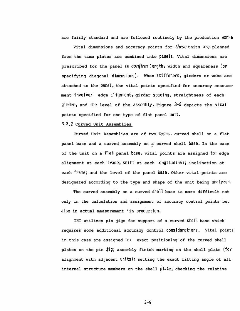
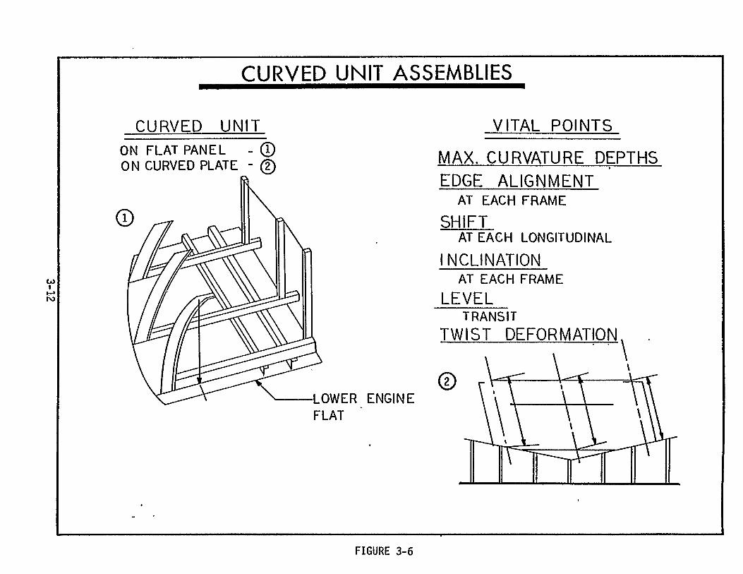
3.3.2 Curved Unit Assemblies
Curved Unit Assemblies are of two types: curved shell on a flat
panel base and a curved assembly on a curved shell base. In the case\
of the unit on a flat panel base, vital points are assigned to: edge
alignment at each frame; shift at each longitudinal; inclination at
each frame; and the level of the panel base. Other vital points are
designated according to the type and shape of the unit being analyzed.
The curved assembly on a curved shell base is more difficult not
only in the calculation and assignment of accuracy control points but
also in actual measurement ’in production.
IHI utilizes pin jigs for support of a curved shell base which
requires some additional accuracy control considerations. Vital points
in this case are assigned to: exact positioning of the curved shell
plates on the pin jig; assembly finish marking on the shell plate (for
alignment with adjacent units); setting the exact fitting angle of all
internal structure members on the shell plate; checking the relative
3-9

. . . . .
Assembly Stagea=-.=mmwwwb m..=’- -..
FLAT UNIT ASSEMBLY
Before being combined with bottom plate
,
VITAL POINTS
Edge Alignment- Every girderboth side~
Girder Spocing -Every frame
Straightness - Each girder
level -9 paints
After being combined with bottom plate
c
FIGURE 3-5
VITAL POINTSLm...w!w,l.w,l-..
Edge alignment -every girderboth side-s
Girder spacing -every frame
R e l a t i v i t y -2 p o i n t s eachedge
Level -9. points
3-1o

dimension between the shell plate edge and the internal structures;
and prevention of deformation which may be caused by welding. Main-
tenance of accurate shapeof the curved shell unit is the overriding
concern during this type of assembly. Figure 3-6 shows these two types
of assemblies and the respective vital points.
Throughout the identification and definition of the vital dimen-
sions and points of measurement for assemblies, Accuracy Control Engi-
neers are concerned with two primary considerations: 1) identification
of the points which will assure the greatest accuracy in the erected
ship configuration; and 2) identification of those points which will
be most difficult to maintain during the assembly process. These con-
siderations are the basis of these Accuracy Control decisions.
3.4 FABRICATION STAGE PLANNING”OF VITAL POINTS
Selection and designation of vital dimensions and measurement
points during the fabrication and sub-assembly stage requires the ex- -
amination of the individual piece parts to be fabricated for each as-
sembly. Maintenance of”high accuracy during the fabrication stage
naturally yields easier and
erection work.
In assignment of vital
more accurate assembly work and ultimately
dimensions and accuracy control points the
fabrication process is viewed from all aspects of marking, cutting,
bending and sub-assembly. Working backward from the accuracy control
planning accomplished on the assembly units, discrete sub-assemblies
and piece parts are identified which must. be controlled in order to
maintain the accuracy required during assembly. The sub~assemblies
and piece parts thus identified are then analyzed as to the fabrication
3-11

processes that must be used to manufacture them and vital dimensionsand
accuracy points specified for each part in each process (i.e. plate
marking, cutting,dimensions and requirements for dimensional checks,
bending dimensions and checks, etc.) Typical vital points specified
for fabricated pieces and sub-assemblies are: length; width; height;
squareness; level; edge condition; deformation caused by welding; twist;
relativity of stiffeners, girders, webs; straightness of stiffeners,
girders, webs; etc.
The identification and designation of these vital points and di-
mensions is disseminated through working drawings, assembly specifi-
cation plans, working instruction plans and through the development
of Accuracy Control Check Sheets which are used throughout the fabri-
cation, sub-assembly, assembly and erection process by workers, Accuracy
Control personnel and Quality Control personnel.
3-13

. . . . . .
SECTION 4
PLANNING FOR ADDITIONAL MATERIAL
4.1 GENERAL
Accuracy Control is effected in several ways in the IHI ship con-
struction process. All of the preliminary and detailed process plan-
ning certainly contributes to better, more accurate fabrication, sub-
assembly, assembly and erection work. The identification and designa-
tion of vital dimensions on working drawings and of vital points of
accuracy measurement in Accuracy Control Check Sheets provides workers,
Assistant Foremen, Foremen, Accuracy Control personnel and Quality
Control personnel with definitive guidelines for exact workmanship
and product standards. However, the maintenance of precise accuracy
at each step of each production stage is virtually impossible due to
the large number of uncontrollable factors present at any given time
in the manufacture of ship piece parts, components and assemblies.
Because of this inability to absolutely control accuracy by any
of the
method
of the
above means IHI has developed a systematized Accuracy Control
for providing additional material in some parts and components
ship. This added material is specified for each fabricated
piece at each production stage. The added material is “cut away” only
when each piece is mounted or affixed to the next larger sub-assembly
or assembly. For example, the added material on individual pieces cut
from plates is removed when these pieces are combined into a flat
panel sub-assembly. The panels of the sub-assembly will also have
added material which will be removed either when that sub-assembly
4-1

becomes part of an assembly or during erection of the assembly if those
panels form part of the exterior of the assembly. Hence, neat cutting
occurs at different points in fabrication, assembly and erection.
The objective of this accuracy control planning is to compensate
for any inaccuracies in layout, burning or fitting and any shrinkage
or-deformation caused by welding. This Accuracy Control planning is
therefore a critical and h“
Control concept.
ghly involved part of the total Accuracy
ADVERSE FACTORSAFFECTING ACCURACY
INACCURACY IN:BURNINGLAYc)UT ) P
SHRINKAGE FROMWELDINGDEFORMATION FROMWELDING
/ /
COMPENSATORYPRACTICE
ACCURACYP~ANNING
A D D I T I O N A LM A T E R I A LPLANNING /
PRELIMINARY I I DETAILPLANNING PLANNING
I
. . I
FIGURE 4-1
4-2

-.— . ..— . ..—. —.- . . . . .—.—— . .—. - —
Actual additional material planning involves two distinct phases
of activity: preliminary planning and
planning concerns the establishment of
detail planning. Preliminary
the added material scheme for .
the entire ship whereas the detail planning is
quirements for added material for detail parts
tures and joints.
4.2 PRELIMINARY PLANNING
In this phase of added material planning,
concerned with the re-
such as internal struc-
Accuracy Control Engi-
neers perform a detailed analysis of key ship construction plans, unit
assembly methods and the erection plan. This analysis involves a re-
view and assessment of the Hull Blocking Plan, mid-ship section and
shell expansion drawings.
.
ADDED MATERIAL PRELIMINARY PLANNING
m/ ... ..- . . . . ... . ..Input Requirements Objective---- . . . - - . . . . . . - ------- --- -.- . . - - --- . - - . . - - - . ------
BLOCKING PLAN SET BASIC POLICY FOR
MID-SHIP SECTION I TOTAL SHIPSHELL EXPANSION :ERECTION PLANSTANDARD SYMBOLS :AfiD AMOUNTS Added Material Set for:/ / .- - -- --- -- -- - - - -- - --- - - - - . - . -- - - .
Z O N E IZ O N E 2ZONE 3
. .
FI’GURE 4-2 ‘
4-3
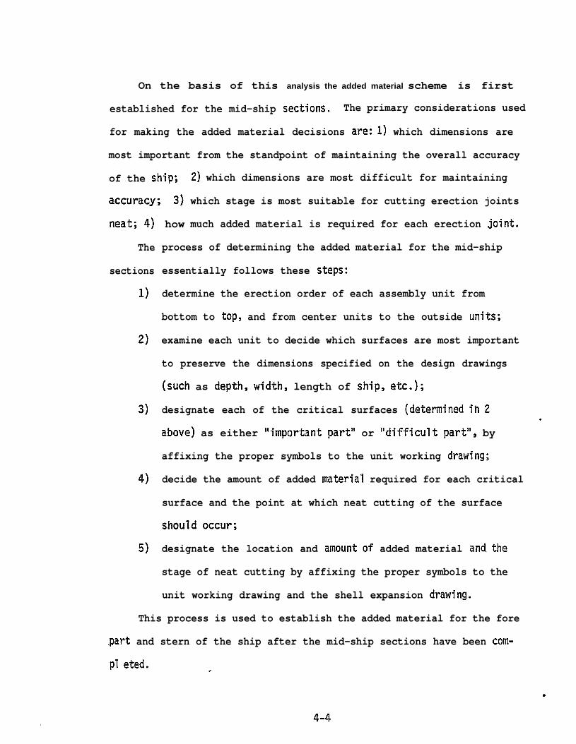
On the basis of this analysis the added material scheme is first
established for the mid-ship sections. The primary considerations used
for making the added material decisions are: 1) which dimensions are
most important from the standpoint of maintaining the overall accuracy
of the ship;
accuracy; 3)
neat; 4) how
2) which dimensions are most difficult for maintaining
which stage is most suitable for cutting erection joints
much added material is required for each erection joint.
The
sections
1)
2)
3)
4)
5)
process of determining the added material for the mid-ship
essentially follows these steps:
determine the erection order of each assembly unit from
bottom to top, and from center units to the outside units;
examine each unit to decide which surfaces are most important
to preserve the dimensions specified on the design drawings
(such as depth, width, length of ship, etc.);
designate each of the critical surfaces (determined ih 2
above) as either “important part” or “difficult part”, by
affixing the proper symbols to the unit working drawing;
decide the amount of added material required for each critical
surface and the point at which neat cutting of the surface
should occur;
designate the location and amountof added material and.the
stage of neat cutting by affixing the proper symbols to the
unit working drawing and the shell expansion drawing.
This process is used to establish the added material for the fore
part and stern of the ship after the mid-ship sections have been com-
pl eted. .
.
●
4-4

—
Subsequent to this Accuracy Control planning for added material,
applicable dimensions and added material information are entered on the
working drawings by the shipyard Design Department Engineers and re-
leased to the yard workshops.
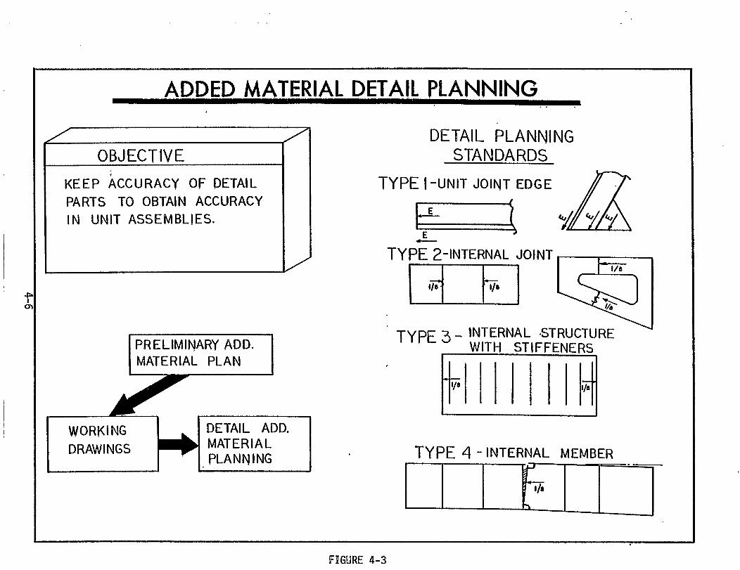
4.3 DETAIL PLANNING
Detail added material planning is concerned with keeping the ac-
curacy of detail parts during fabrication, sub-assembly and assembly.
This effort is based on the preliminary planning and is accomplished
by the design engineers in the Design Department.
As in the preliminary planning each of the component parts of a
sub-assembly or assembly is examined together with the necessary pro-
duction processes which must be applied in their manufacture. Deci-
sions are made concerning the most important dimensions, the most ap-
propriate stage (or sub-stage) for neat cutting, and how much added
material is required for each surface of a fabricated item. Neat
cutting can be designated at the cutting (burning) sub-stage, after
bending or flaming, or after joining either at the sub-assembly or
assembly stage.
The process used by design
requirements is similar to that
engineers in determining added material,
used by the Accuracy Control Engineers
in the preliminary planning.
mine the breakdown of pieces
processes through which each
to decide which surfaces are
Block Assembly
and sub-assembl-
piece must flow
critical to the
Plans are used to deter-
es and the fabrication
Each piece is examined
accuracy of the subsequent
sub-assembly or assembly, which surfaces will be most difficult in
which to preserve accuracy, and which dimensions are most important
4-5


t
:f
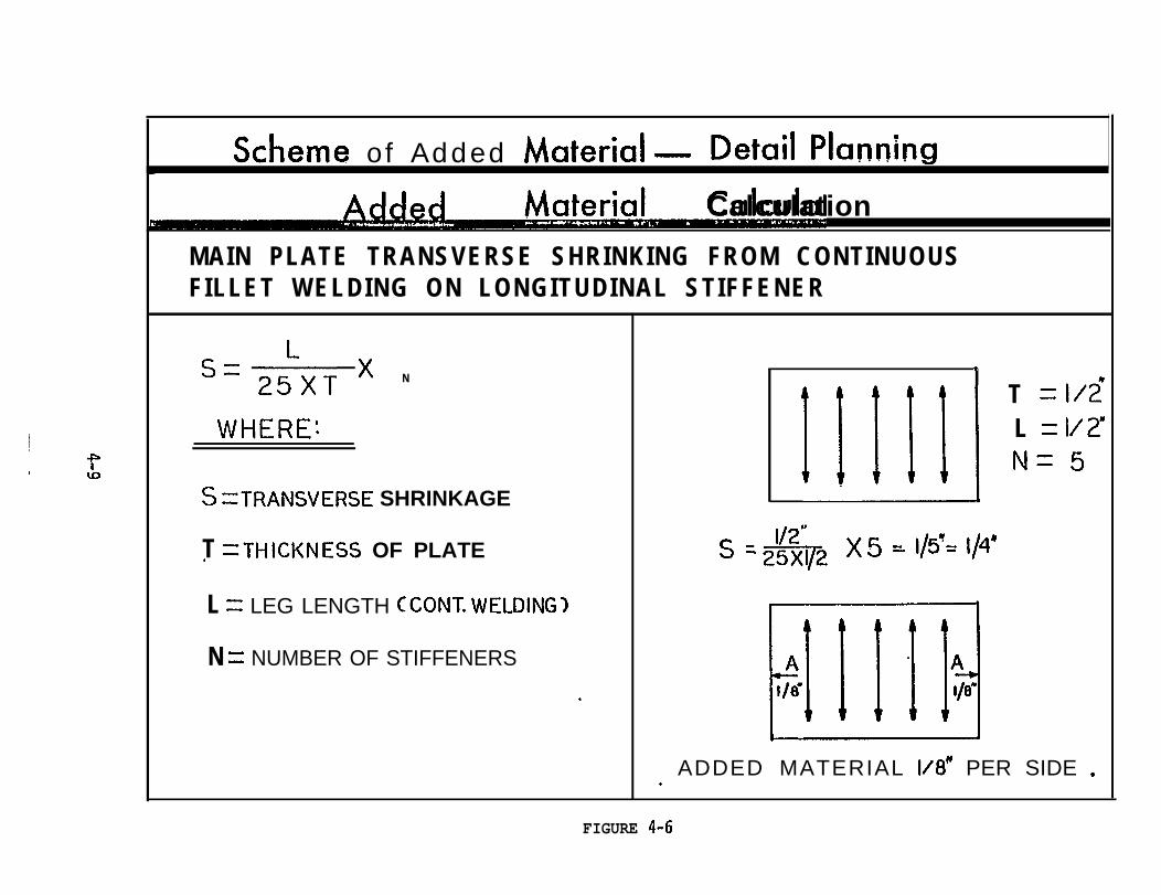
scheme of Added Material — Detail Planning
~Calculation
MAIN PLATE TRANSVERSE SHRINKING FROM CONTINUOUSFILLET WELDING ON LONGITUDINAL STIFFENER
s=2:XT x N
+
11111, T = 1/2!WHERE: L = 1/2”
N=5S =TRANSVERSE SHRINKAGE
T =THICKNESS OF PLATE1/2”
s ‘m’/2f )(5 = 1/5”= 1/4”
L = LEG LENGTH CCONT. WELDING]
N = NUMBER OF STIFFENERS PI @*ADDED MATERIAL 1/8” PER SIDE ..
~111]1Ad1/(3” 1/8’
FIGURE 4-6
SECTION 5
ACCURACY CONTROL BASE LINES
5.1 GENERAL
Another aspect of Accuracy Control planning is that concerned with
the establishment of base lines for fabricated pieces and assemblies.
These base lines are used at each stage of production to obtain accu-
racy in cutting, shaping and preserving the proper relationship between
component parts on the sub-assembly, assembly and erection units.
Accuracy Control Engineers perform the basic (preliminary) plan-
ning for these base lines in conjunction with mold loft personnel.
Implementation of base line information is accomplished by the mold
loft for fabricated pieces”and by Accuracy Control during the assembly
and erection stages.
tion of base lines at
cation) the provision
The basic planning consists of the identifica-
each production stage and (in the case of fabri-
of guidelines to the mold loft for preparation
of N/C tapes, instructions for manual marking and for preparation of
base line marking tapes (i.e. metal strips used by workers to determine
base lines on fabricated parts, sub-assemblies and assemblies.)
Essentially there are three types of base lines: check line for
cutting; check line for shaping; and base-line for relationship be-
tween materials.
5.2 CHECK LINE FOR CUTTING
This base line is applied to flat plates which are to be cut in
a straight or curved line either by an N/C burning machine or manually.
Usually the check (base) line is planned at a constant dimension
5-1

.
of two inches inside the cut line. In the case of a straight line cut,
the checking line is planned by the mold loft for materials having a
straight joint such as internal structures which will be joined to flat
panels.
Check lines for materials such as engine flats or curved web
frames, which must be cut manually, are similarly placed inside the
cutting line usually by hand using some sort of jig. In this case the
check line serves as a guide during the manual cutting and also as a
constant reference in determining the accuracy of the cut line.
Figure 5-1 shows the application of these check lines.
STRAIGHT LINES
— CUITING LINE
‘——- BASE LINE (EACH SIDE)
I I ?I 1II :I :.II I
1. Usually 2“ from cut
2. Planned by Mold Loft
3. Base line marked by N/C machine
4. Burning by N/C machine
CURVED LINES
— CUTTING LINE
-—--BASE LINE
1. Planned byA.C.
2. Base line manually marked
3. Manually c u t
BASE LINES FOR CUTTING .,.
FIGURE 5-1
5-2

5.3 CHECK LINE FOR SHAPING
In order to maintain the shape of curved units having no straight
edge or line, a base line is established by the Accuracy Control group
to assure that the shape conforms to drawing requirements and that dis-
tortion does not occur after welding.
This base line is marked either by the N/Cmachine or manually
using an appropriate jig. The line usually extends the full length of
the curved component and as a “rule of thumb” about five times the
width of the component.
BASELINESTYPE2- A C - O R SHAPINGb-%---.&-----a---- b..a%x-m****\\\,9• ..9 ● -m-.---.x-. . b - b -k -.-..
APPLICATION TO CURVED INTERNALSTRUCTURE HAVING NO STRAIGHT LINE
t CEG. CURVED WEB)- ESPECIAUYUNITSHAVING SUB-ASSEMBLY JOINTS.
8ASE LINE FORSHAPE
JOINING BASELINE
BASE LINES FOR SHAPING .-
FIGURE 5-2
5-3
—. — .- .
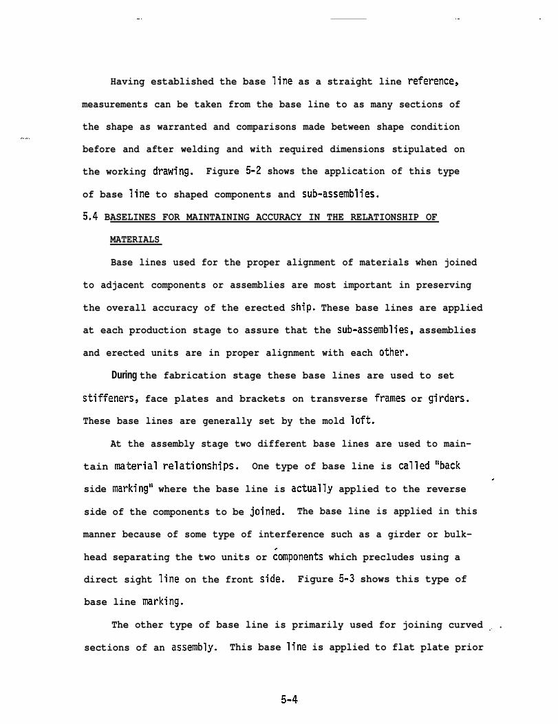
Having established the base line as a straight line reference,
measurements can be taken from the base line to as many sections of
the shape as warranted and comparisons made between shape condition—.
before and after welding and with required dimensions stipulated on
the working drawing. Figure 5-2 shows the application of this type
of base line to shaped components and sub-assemblies.
5.4 BASELINES FOR MAINTAINING ACCURACY IN THE RELATIONSHIP OF
MATERIALS
Base lines used for the proper alignment of materials when joined
to adjacent components or assemblies are most important in preserving
the overall accuracy of the erected ship. These base lines are applied
at each production stage to assure that the sub-assemblies, assemblies
and erected units are in proper alignment with each other.
During the fabrication stage these base lines are used to set
stiffeners, face plates and brackets on transverse frames or girders.
These base lines are generally set by the mold loft.
At the assembly stage two different base lines are used to main-
tain material relationships. One type of base line is called “back
side marking” where the base line is actually applied to the reverse.
side of the components to be joined. The base line is applied in this
manner because of some type of interference such as a girder or bulk-
head separating the two units or ~omponents which precludes using a
direct sight line on the front side. Figure 5-3 shows this type of
base line marking.
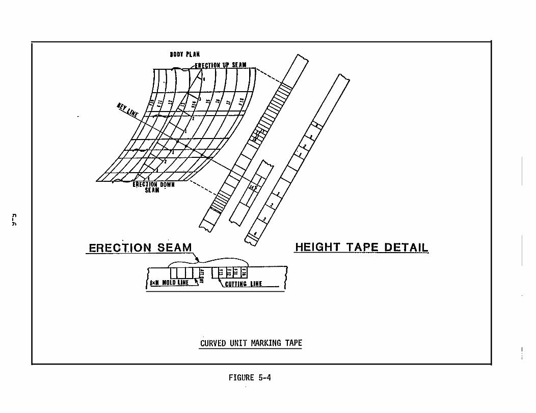
The other type of base line is primarily used for joining curved . .
sections of an assembly. This base line is applied to flat plate prior
5-4

CASE I : Back side marking on girders between double bottom units.
CASE 11 : Back side marking on t-top between stools and double bottom.
CASE 111: Back side marking on slant plate.
CASE IV : Back side marking on top side tank bottom plate.
ASSEMBLY BASE LINES
FIGURE 5-3
._.. _.
,
1-
?-
SC5iiiz-
5-6
uL

curved plate assemblies. These marking tapes are thin metal strips
precisely measured to show the reference points applicable to a specific
plate. Using the marking tapes each curved assembly plate is checked
for proper configuration and proper position of the base line (after
bending). This checking of each bent plate assures successful align-
ment of the plates on the pin jig and with adjacent mating plates.
Figure 5-4 illustrates a typical Curved Unit Assemb?y Marking Tape.
Another important base line applied during the assembly process
is the base line for alignment of completed curved units. For example,
.
I
ASSEMBLY BASE LINE MARKING
(CURVED UNITS)
FIGURE 5-5
5-7

where many units are mounted one on top of another in a continuous
curved section of the ship (e.g. bow sections), a base line is estab-
lished that runs through the center of the units in an oblique direc-
tion. Matching these base lines allows proper alignment of each unit
as it is mounted. Figure 5-5 shows this type of base line.
During the erection stage two types of base lines are used. The
first base line is physically marked on the shipways to show the abso-
lute ship center line and the aft butt position of the first unit to be
landed on the ways. Additionally, specific unit base lines are marked
for many of the bottom assemblies on the ways. For example, the for-
ward end frame position of each unit for the ship’s fore part and stern
are marked and the aft end frame position of each unit for the mid-
ship sections. Watertight bulkhead positions, the aft perpendicular
and the forward perpendicular points are also marked..Accuracy Control Engineers are responsible for the planning and.
actual marking of these base lines on the ways. The plan for the lay-
out of these base lines is usually contained in the cribbing plan.
The second type of base line used for erection is marked on each
unit prior to movement to the erection area. Both the planning of
these lines and the actual marking is accomplished by Accuracy Control
Engineers. These base lines are used to set completed assembly units
in position on lower units in the erection sequence and for aligning
each unit fore and aft with adjacent units. These are called base
lines for shipwrighting.
5-8
..
SECTION 6
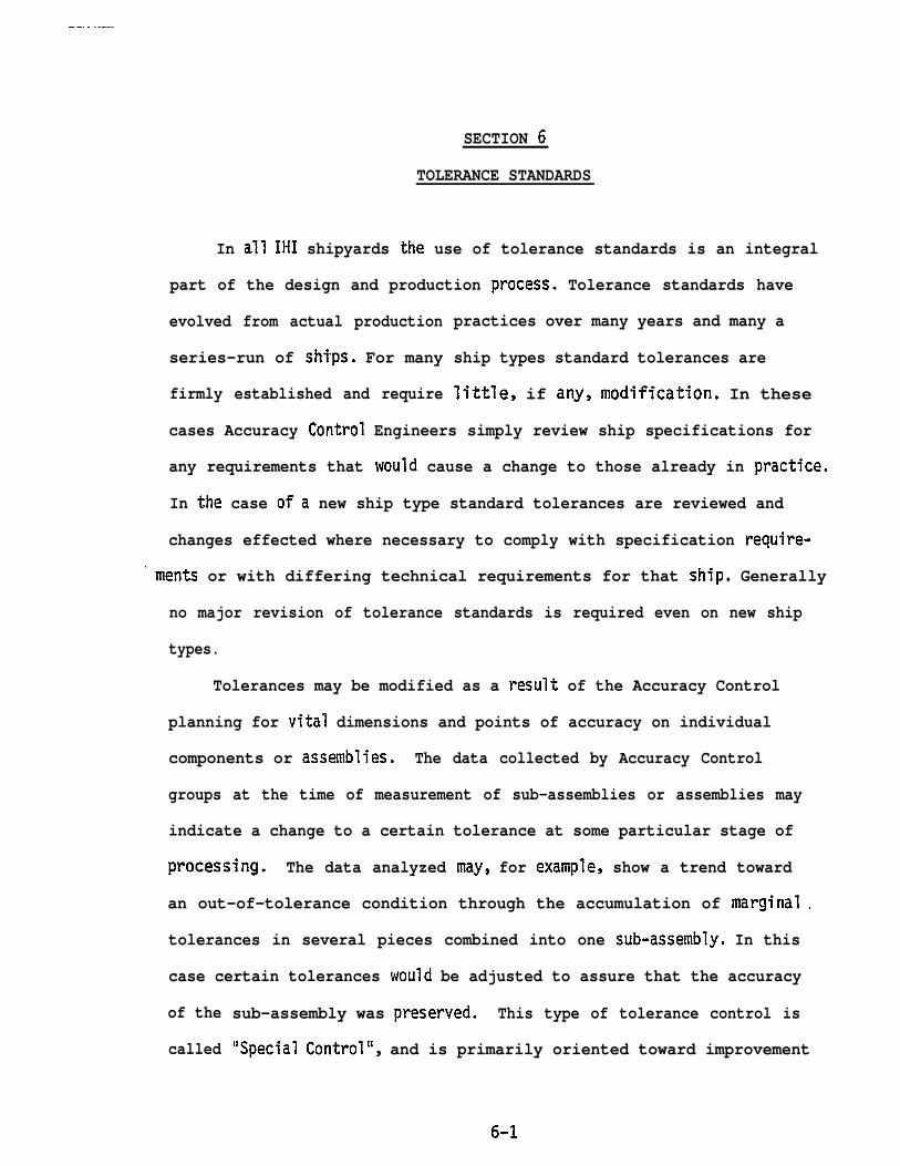
TOLERANCE STANDARDS
In all IHI shipyards the use of tolerance standards is an integral
part of the design and production process. Tolerance standards have
evolved from actual production
series-run of ships. For many
firmly established and require
practices over many years and many a
ship types standard tolerances are
little, if any, modification. In these
cases Accuracy Control Engineers simply review ship specifications for
any requirements that would cause a change to those already in practice.
In the case ofa new ship type standard tolerances are reviewed and
changes effected where necessary to comply with specification require-
“ ments or with differing technical requirements for that ship. Generally
no major revision of tolerance standards is required even on new ship
types.
Tolerances may be modified as a result of the Accuracy Control
planning for vital dimensions and points of accuracy on individual
components or assemblies. The data collected by Accuracy Control
groups at the time of measurement of sub-assemblies or assemblies may
indicate a change to a certain tolerance at some particular stage of
processing. The data analyzed may, for example, show a trend toward
an out-of-tolerance condition through the accumulation of marginal .
tolerances in several pieces combined into one sub-assembly. In this
case certain tolerances would be adjusted to assure that the accuracy
of the
called
sub-assembly was preserved. This type of tolerance control is
“Special Control”, and is primarily oriented toward improvement
6-1

.- ——.—. . ..z
‘of tolerance standards for a particular ship type.
A second type of control is called “Regular Control” and is con-
cerned with the routine tolerance accuracy of the fabricated pieces—.. -
of any ship and with the accuracy maintenance of the machines which
process those pieces.
Accuracy Control Engineers are responsible for field checks of
both the fabricated pieces and of the related machines such as the
N/C burning machine, the flame planer and all welding machines. Re-
sults of these field checks are analyzed and plotted on time-based
control charts to detect any increase in out-of-tolerance performance.
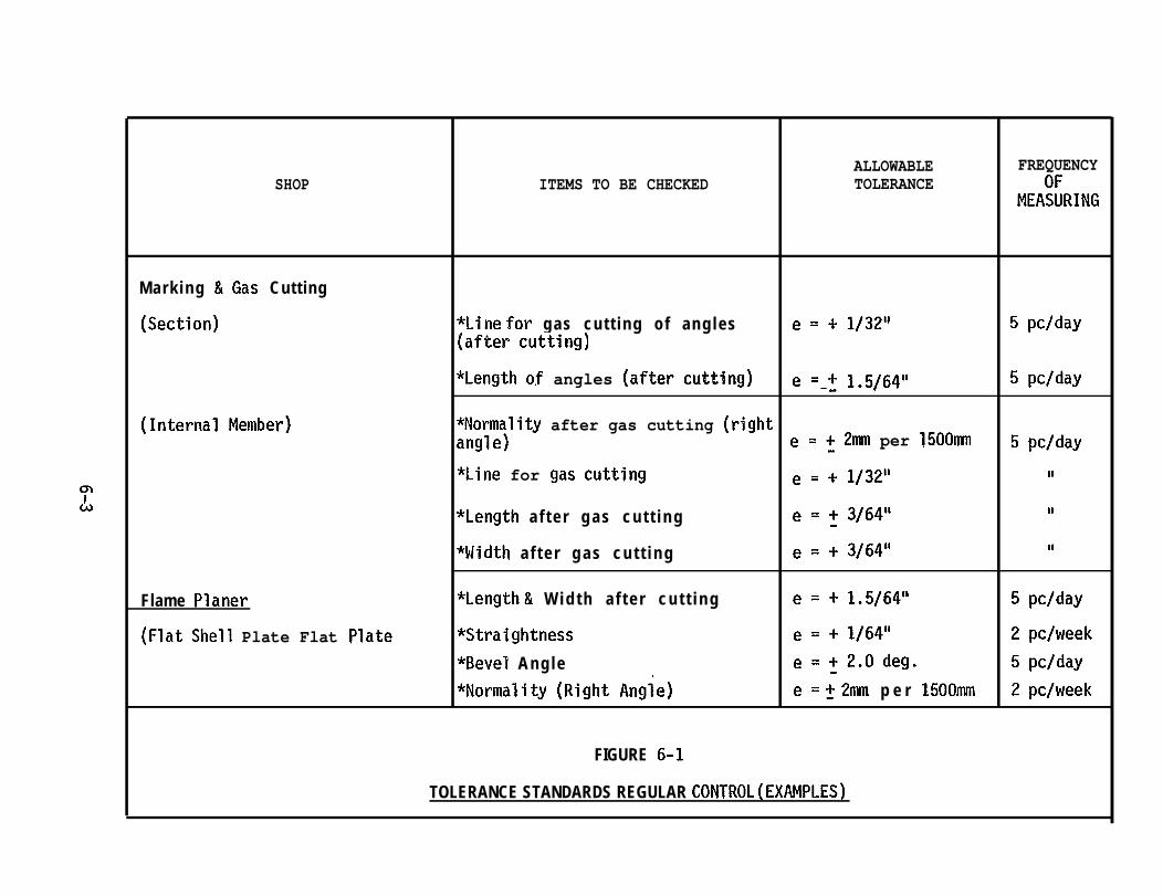
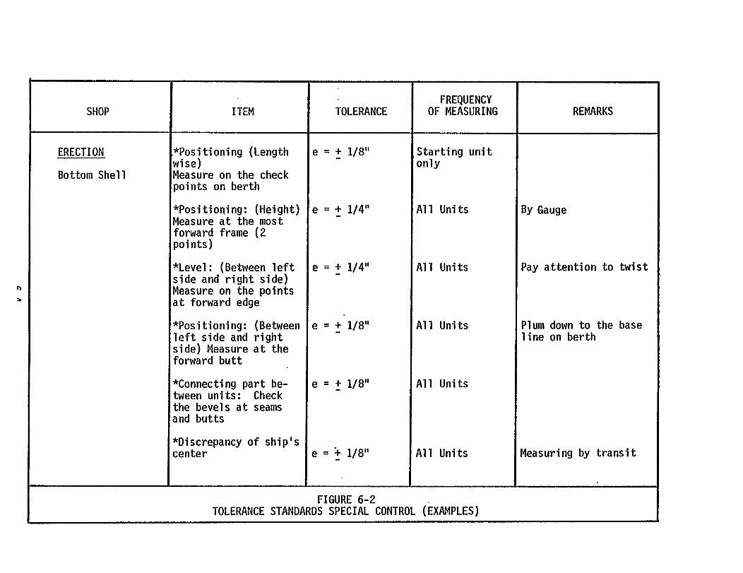
Figures 6-1 and 6-2 present examples of the standard tolerances
established for each type of control.
In IHI a well developed set of standards provide detailed infor-
mation to designers, planners, production workers and Quality Control
Inspectors throughout the ship construction process. These standards
have been included in the Livingston Technology Transfer Program Final
Report on Quality Assurance.
6-2
ALLOWABLE FREQUENCYSHOP ITEMS TO BE CHECKED TOLERANCE
MEA:~RING
Mark ing &Gas Cutting
(Section) *Line for gas cut t ing of angles e = + 1/32’1 5 pc/day(after cutting)
*Length o.f angles (after cutting) e ‘.? 1.5/64” 5 pc/day
(Internal Member) *Normality after gas cutting (rightangle) e = ~ 2mm per 1500~ 5 pc/day
*Line for gas CUtting e s + I/3211 II
e = f 3/64” II*Length a f t e r g a s c u t t i n g
*ldidth a f t e r g a s c u t t i n g e = + 3/64” II
Flame Planer *Length & W i d t h a f t e r c u t t i n g e = + 1.5/64” 5 pc/day
(Flat Shell Plate Flat Plate *Straightness e = + 1/64” 2 pc/week
*Bevel Angle e = ~ 2.o deg. 5 pc/day
*Normality (Right Angle) e = f 2mm p e r 1500mm 2 pc/week
FIGURE 6-1
TOLERANCE STANDARDS REGULAR CONTROL ( EXAMPLES)
SECTION 7
CONCLUSION
The planning functions of Accuracy Control are an integral part of
the total production planning process. The participation of Accuracy
Control Engineers with designers and production planners in the design
development, the ship breakdown, ’and in the determination of production
processes, methods and techniques is a sophisticated and highly devel-
oped aspect of the LHI production planning and control system. Although
t h e a c t i v i t i e s o f A c c u r a c y C o n t r o l a r e s e p a r a t e l y identifiable, in .
reality the production planning system functions as a group effort with
contributions from many different groups to a cohesive and comprehen-
sive manufacturing plan.
Accuracy Control planning can be seen as a discrete sub-system
within the overall planning system. Accuracy Control planning-consists
of two basic elements: participation in production planning; and the
development of specific inputs to the detailed Assembly Specification
Plans, the working drawings and the Working Instruction Plans for each
assembly unit. This planning forms the basis not only for the control
of accuracy but also for
equipment throughout the
accomplished by Accuracy
the uti l izat ion of facilities, m a n p o w e r a n d
p r o d u c t i o n process. In effect the planning
Control Engineers in the preliminary planning
stages establishes the operations and practices to be observed during
the entire ship construction program.
Although the emphasis of the Accuracy Control Engineers is on
maintaining precision at each stage of production, the requirements
.
7-1
-—. . . . . . . .
stipulated in detailed plans for achieving that precision necessitate
particular processes, methods and techniques. These requirements there-
fore regulate and control the production system, the quality of the end
product, and ultimately the productivity of the production process.
The planning, by itself, is of course no guarantee of proper exe-
cution, however, the Accuracy Control system does not end with planning.
The field activities of Accuracy Control ensure that the planning is
properly and through the Accuracy Control data collection,
and feedback activities, that the production system is con-
improved.
concept and system of Accuracy Control within IHI thus operates
e x e c u t e d
a n a l y s i s
tinually
The
through the entire design/production process to plan and specify ac-
curacy and production requirements, to monitor and measure the product
and the production system, and to perpetually refine and improve the
products, the production system and the producti~ity of the IHI yards.
. .
7-2

.