special specification 5876 city of lampasas water...
TRANSCRIPT

1-59 5876 12-11
2004 Specifications CSJ 0251-06-026, Etc & 0231-17-009
SPECIAL SPECIFICATION
5876
City of Lampasas Water and Wastewater Utilities 1. Description
This Item will govern the installation of water and wastewater facilities belonging to the City of Lampasas. The Contractor and approved Subcontractors will construct all required utility adjustments within the limits of this project including any peripheral adjustments that may not have been discovered during the design process. These adjustments shall be paid for directly as detailed as follows:
SECTION 02242
CEMENT-STABILIZED SAND BACKFILL
PART 1 – GENERAL 1.01 DESCRIPTION
This Section includes all plant, labor, equipment, supervision, and tools for the furnishing and installation of Cement-Stabilized Sand Backfill as shown on PLANS and as indicated in other Sections of the TECHNICAL SPECIFICATIONS.
1.02 RELATED REQUIREMENTS
Related work as called for on PLANS or specified elsewhere in this or other TECHNICAL SPECIFICATIONS.
1.03 – 1.11 (NOT USED) PART 2 – PRODUCTS 2.01 MATERIALS
A. Aggregate: Deleterious materials in sand not to exceed the following limits, by weight:

2-59 5876 12-11
1. Material removed by decantation 5.0% Clay lumps 0.5% Other deleterious substances (e.g. coal, shale, coated grains of soft flaky particles) 2.0%
2. Gradation Requirements:
Sieve Size % Retained
1/4″ 0-5
No. 40 0-40
No. 100 70-100
No. 200 95-100
3. Color test ASTM C40. Color is not to be darker than standard color. B. Plasticity Index: 10 or less when tested in accordance with ASTM D4318. C. Cement: ASTM C150, Type I. D. Water: Fresh and clean.
PART 3 – EXECUTION 3.01 MIXING
Use not less than 1½ sacks of cement per cubic yard of mixture. Use amount of water required to provide mix suitable for mechanical hand tamping and mix in mixer to obtain specified results. Material not in place within 1½ hours after mixing or that has obtained an initial set will be rejected and removed from the site.
3.02 PLACING
Place at locations indicated on PLANS and in TECHNICAL SPECIFICATIONS. Place in maximum 8″ lifts and compact each lift with power-driven mechanical tampers. Compact to a minimum dry density of 102 pounds per cubic foot. Place around cast-in-place concrete structures only after they have cured for at least four days.
3.03 - 3.10 (NOT USED) 3.11 MEASUREMENT AND PAYMENT
No separate measurement or payment for work performed under this Section. Include cost of same in Contract price bid for work of which this is a component part.
END OF SECTION

3-59 5876 12-11
SECTION 02313
BORING AND JACKING
PART 1 - GENERAL 1.01 SUMMARY
The work under this Section includes furnishing and installing of encasement pipe and carrier pipe by methods of jacking and boring as indicated on the Drawings and in conformity with this specification. This item shall also include, but not be limited to other constructions activities such as excavation, removal of all materials encountered in jacking or boring pipe operations, ground water control and disposal, safety facilities, disposal of all material not required in the work, grouting, bulkhead installation, backfilling and re-vegetation.
1.02 RELATED REQUIREMENTS (NOT USED) 1.03 REFERENCES
The publications listed below and the references included there in form a part of this specification to the extent referenced. The publications are referred to in the text by basic designation only. The referenced publication refers to the most recent editions or publications.
AMERICAN WATER WORKS ASSOCIATION (AWWA)
AWWA C200 1997 Steel Water Pipe - 6-Inch (150mm) and Larger
AWWA C203 1997 Coal-Tar Protective Coatings and Linings for Steel Water Pipelines-Enamel and Tape-Hot Applied.
1.04 – 1.05 (NOT USED) 1.06 SUBMITTALS
A. Make all submittals in accordance with the requirements of Section 01300, “Submittals”.
B. At least 30 days prior to the start of boring and jacking construction, the
CONTRACTOR shall submit a description of its tunneling operations to the ENGINEER. The submittal shall include descriptions of the proposed site facilities, equipment to be utilized, and methods of construction. The ENGINEER shall review these descriptions for compliance with Contract requirements. The descriptions shall include, but not be limited to:

4-59 5876 12-11
1. Shop drawings identifying proposed jacking or boring method complete in assembled position.
2. Trench Safety Plan including pits, trenches and sheeting or bracing if necessary.
3. Design for jacking or boring excavation equipment. 4. Installation of jacking or boring supports or back stop. 5. Arrangement and position of jacks and pipe guides. 6. Grout material and procedures for filling annular space between the
encasement pipe and the surrounding excavated material.
1.07 QUALITY ASSURANCE (NOT USED) 1.08 DELIVERY, STORAGE AND HANDLING
Handle, ship and store material in a manner that will prevent distortion or other damage. Store material in a clean, properly drained location out of contact with the ground. Replace all damaged material with new material or repair the damaged material in a manner approved by the ENGINEER.
1.09– 1.11 (NOT USED)
PART 2 - PRODUCTS 2.01 MANUFACTURER (NOT USED) 2.02 MATERIALS
A. Encasement pipe to be steel pipe in accordance with AWWA C200, butt-welded joints in accordance with AWWA C200 Section 4. Pipe to be at least 4-inches larger in diameter than the largest outside diameter of carrier pipe. Wall Thickness to be in accordance with the following table:
Encasement Pipe Minimum (Outside Diameter) Thickness
15-inch to 35-inch 3/8-inch 36-inch to 42-inch 1/2-inch 48-inch to 66-inch 5/8-inch
Coating of the encasement pipe and field repairs to be in accordance with AWWA C203, Coal Tar Coatings - Hot Applied Factory Application.
B. Carrier pipe to be PVC, according to Section 02615, “Polyvinyl Chloride (PVC) Sewer Pipe and Fittings.”

5-59 5876 12-11
C. Encasement spacers manufacturer and model number to be as shown on the PLANS.
2.03 DELIVERY, STORAGE AND HANDLING
Handle, ship and store material in a manner that will prevent distortion or other damage. Store material in a clean, properly drained location out of contact with the ground. Replace all damaged material with new material or repair the damaged material in a manner approved by the ENGINEER.
PART 3 - EXECUTION
3.01 GENERAL
A. CONTRACTOR to install encasement pipe, carrier pipe, spacers and end seals as
indicated on PLANS and in accordance with manufacturer’s recommendations. B. The Contractor shall have sole responsibility for the safety of the jacking and
boring operations and for persons engaged in the work. The Contractor shall conform to the requirements in accordance with Section 02161 “Trench Excavation and Shoring Safety Plan”.
C. When the grade of the pipe at the jacking or boring end is below the ground
surface, suitable pits or trenches shall be excavated to provide sufficient room to conduct the jacking or boring operations and for placement of end joints of the pipe.
D. The pipe shall be jacked or bored from the low or downstream end, if possible.
Lateral and vertical variation in the final position of the encasement or carrier pipe from the line and grade established by the Engineer will be permitted only to the extent of 1 (one) inch laterally and vertically per 20 feet of pipe, provided that such variation shall be regular and continuous only (no bows or reverse curve sections) in one direction and that the final grade of flow line shall be in the direction indicated on the PLANS.
E. Immediately after jacking or boring is complete and the encasement pipe is
accurately positioned and approved for line and grade, the clear space between the pipe and the surrounding excavated material shall be completely filled by pressure grouting for entire length of installation.
F. After placement of the carrier pipe is complete, the ends of the encasement pipe
shall be sealed per PLANS. 3.02 PREPARATION (NOT USED)

6-59 5876 12-11
3.03 ERECTION/INSTALLATION A. Jacking
1. Heavy duty jacks suitable for forcing the pipe through the embankment shall be provided. In operating the jacks, an even pressure shall be applied to all jacks used so that the pressure will be applied to the pipe uniformly around the ring of the pipe. A suitable jacking frame or back stop shall be provided. The pipe to be jacked shall be set on guides properly braced together, to support the section of the pipe and to direct it in the proper line and grade. The complete jacking assembly shall be placed in order to line up with the direction and grade of the pipe. In general, the embankment material shall be excavated just ahead of the pipe, the material removed through the pipe and the pipe forced through embankment by jacking, into the space thus provided.
2. The distance that excavation shall extend beyond the end of the pipe depends on the character of material encountered, but it shall not exceed 2 feet (0.6 meter) in any case. This distance shall be decreased, when directed by the Engineer or designated representative, if the character of the material being excavated makes it desirable to keep the advance closer to the end of the pipe.
3. The Contractor may use a cutting edge of steel plate around head end of the pipe extending a short distance beyond the end of pipe with inside angles or lugs to keep the cutting edge from slipping back onto the pipe.
4. When jacking of the pipe is begun, all operations shall be carried on without interruption, insofar as practical, to prevent the pipe from becoming firmly set in the embankment.
5. Any pipe damaged in jacking operations shall be removed and replaced by the Contractor at its entire expense.
B. Boring
1. The boring shall proceed from a work pit provided for the boring equipment and workmen. The location of the pit shall be approved by the Engineer or designated representative. The boring shall be done mechanically using either a pilot hole or the augur method.
2. In the pilot hole method an approximate 2 inch (50 mm) pilot hole shall be bored the entire length of the crossing and shall be checked for line and grade on the opposite end of the bore from the work pit. This pilot hole shall serve as the centerline of the larger diameter hole to be bored.
3. When the augur method is used, a steel encasement pipe of the appropriate diameter equipped with a cutter head to mechanically perform the excavation shall be used. Augurs shall be of sufficient diameter to convey the excavated material to the work pit.
4. Excavated material will be removed from the working pit and disposed of properly. The use of water or other fluids in connection with the boring operation will be permitted only to the extent to lubricate cuttings. Water jetting will not be permitted.

7-59 5876 12-11
5. In unstable soil formations, a gel-forming colloidal drilling fluid, that consists of at least 10 percent of high grade carefully processed bentonite, may be used to consolidate the drill cuttings, seal the walls of the hole and furnish lubrication to facilitate removal of the cuttings from the bore.
C. Grouting
1. All space between the encasement pipe and the bored excavation shall be pressure filled with grout immediately upon completion of installation of encasement pipe with a procedure that ensure complete filling of the annulus, the encasement pipe is undamaged by grouting and the encasement pipe is on design line and grade.
D. Installing Carrier Pipe
1. After the encasement pipe has been completely installed, the CONTRACTOR shall thoroughly clean the interior. The CONTRACTOR shall place the carrier pipe within the encasement pipe using wooden skids, steel rails or casing spacers insulators, whichever is shown on the PLANS.
2. After carrier pipe is installed within the encasement pipe and prior to encasement pipe ends installation, the CONTRACTOR shall conduct the required pressure and leakage test on the carrier pipe. Any leaks which are discovered during the testing phase shall be repaired to the satisfaction of the Engineer.
3. The carrier pipe shall be installed to the exact line and grade required within the casing, and, after it has been satisfactorily placed and approved by the Engineer, end seals are to be installed at each end of the encasement pipe.
3.04 - 3.10 (NOT USED) 3.11 MEASUREMENT AND PAYMENT
A. Unless otherwise indicated, no separate payment for work performed under this Section if noted as such on the PLANS. Include cost of same in Contract price bid for work of which this is a component part.
B. When indicated in the BID documents, measure “Boring and Jacking” covered by
this Specification Section of length specified on PLANS by linear foot of pipe complete in place. Such measurement to be made between the ends of the pipe along the central axis installed. The Work to be paid for at the unit price bid per linear foot for “Boring and Jacking”, which price shall be full compensation for furnishing all materials, encasement and carrier pipes, linear materials required, for all preparation, hauling and installing of same and for all labor, tools, equipment and incidentals necessary to complete the Work, including excavation, backfilling, and disposal of surplus material.
END OF SECTION

8-59 5876 12-11
SECTION 02518
PRECAST CONCRETE MANHOLES PART 1 – GENERAL 1.01 SUMMARY
This Section includes the furnishing and installation of Precast Concrete Sanitary Sewer or Storm Sewer Manholes and accessories required for a complete installation at the location(s) as shown on the PLANS.
1.02 RELATED REQUIREMENTS
Related work as called for on PLANS or as specified in this or other TECHNICAL SPECIFICATIONS.
1.03 REFERENCES
The publications listed below form a part of this Specification to the extent referenced. The publications are referred to in the text by basic designation only.
AMERICAN NATIONAL STANDARDS INSTITUTE (ANSI) ANSI B16.1 Cast Iron Pipe Flanges and Flanged Fittings
AMERICAN SOCIETY FOR TESTING AND MATERIALS (ASTM) ASTM A307 Specification for Carbon Steel Bolts and Studs, 60,000 psi Tensile ASTM C270 Specification for Mortar for Unit Masonry ASTM C443 Standard Specification for Joints for Circular Concrete Sewer and
Culvert Pipe, Using Rubber Gaskets ASTM C478/C478M Standard Specification for Precast Reinforced Concrete Manhole
Sections ASTM C923/C923M Standard Specification for Resilient Connectors Between
Reinforced Concrete Manhole Structures and Pipes ASTM C924/C924M Standard Practice for Testing Pipe Sewer Lines ASTM C1107 Packaged Dry, Hydraulic-Cement Grout (Nonshrink)

9-59 5876 12-11
ASTM D698 Test Method for Laboratory Compaction Characteristics of Soil Using Standard Effort (12,400 ft-lb/ft³)
ASTM D2665 Specification for Poly (Vinyl Chloride) (PVC) Plastic Drain,
Waste and Vent Pipe and Fittings ASTM D2996 Specification for Filament-Wound Fiberglass (Glass-Fiber-
Reinforced Thermosetting Resin) Pipe ASTM D2997 Specification for Centrifugally Cast Fiberglass (Glass-Fiber-
Reinforced Thermosetting Resin) Pipe
AMERICAN WATER WORKS ASSOCIATION (AWWA) AWWA C213 Fusion Bonded Epoxy Coating for the Interior and Exterior of
Steel Water Pipelines 1.04 - 1.05 (NOT USED) 1.06 SUBMITTALS
Submit the following in accordance with Specification Section-01300 Submittals. Submit manufacturer’s data and details of the following items: A. Shop drawings of manhole sections and base units and construction details,
including reinforcement, jointing methods, materials and dimensions. B. Summary of criteria used in the manhole design including, as a minimum,
material properties, loadings, load combinations and dimensions assumed. Include certification from manufacturer that precast manhole design is in full compliance with ASTM C478/ C478M and design criteria as established in Paragraph 2.02.A.5 of this Section.
C. Frames, grates, rings and covers. D. Materials to be used in fabricating drop connections. E. Materials to be used for pipe connections at manhole walls. F. Materials to be used for stubs and stub plugs, if required. G. Materials and procedures for corrosion-resistant liner and coatings, if required. H. Plugs to be used for sanitary sewer hydrostatic testing. I. Manufacturer’s data for pre-mix (bag) concrete, if used for channel inverts and
benches.

10-59 5876 12-11
1.07 – 1.11 (NOT USED) PART 2 – PRODUCTS 2.01 MANUFACTURER(S) (NOT USED) 2.02 MATERIALS AND/OR EQUIPMENT
A. Precast Concrete Manholes 1. Provide manhole sections, base sections, and related components
conforming to ASTM C478/C478M. Provide base riser section with integral floors, unless shown otherwise on PLANS. Provide adjustment rings which are standard components of the manufacturer of the manhole sections. Mark date of manufacture and name or trademark of manufacturer on inside of barrel.
2. Provide barrels constructed from 48-inch diameter standard reinforced concrete manhole sections unless otherwise indicated on PLANS. Combine various lengths of manhole sections to total the correct height with the fewest joints. Wall sections to be designed for depth and loading conditions as required in Paragraph 2.02 A.5, but not to be less than 5 inches thick. Base section to have a minimum thickness of 12 inches under the invert.
3. Provide cone tops to receive cast iron frames and covers designed to support an H-20 loading, unless indicated otherwise.
4. Where the PLANS indicate that manholes larger than 48-inch diameter are required, precast base sections of the required diameter shall be provided with flat slab top precast sections used to transition to 48-inch diameter manhole access riser sections. Transition can be concentric or eccentric. The transition to be located to provide a minimum of 7-foot head clearance from the top of bench to underside of transition.
5. Design Loading Criteria: The manhole walls, transition slabs, cone tops, and manhole base slab to be designed, by the manufacturer, to the requirements of ASTM C478/C478M for the depth as shown on PLANS and to resist the following loads. a. AASHTO H-20 loading applied to the manhole cover and load
transmitted down to the transition and base slabs. b. Unit soil weight of 120 pcf located above all portions of the
manhole, including base slab projections. c. Lateral soil pressure based on saturated soil conditions, producing
an at-rest equivalent fluid pressure of 100 pcf. d. Internal liquid pressure based on a unit weight of 63 pcf. e. Dead load of manhole sections fully supported by the transition
and base slabs. 6. Design: The manhole walls, transition slabs, cone tops, and manhole base
slab to be designed according to the requirements of ASTM C478/C478M and the following.

11-59 5876 12-11
a. Design additional reinforcing steel to transfer stresses at openings. b. Wall loading conditions:
(1) Saturated soil pressure acting on an empty manhole. (2) Manhole filled with liquid to mid-height from invert to
cover, with no balancing external soil pressure. c. The minimum clear distance between any two wall penetrations to
be 12 inches or half the diameter of the smaller penetration, whichever is greater.
7. Provide joints between sections with O-ring gaskets conforming to ASTM C445.
B. Concrete
1. Conform to requirements of Section 03001, “Concrete”. 2. Channel Inverts: Concrete for inverts not integrally formed with manhole
base shall be either five sack pre-mix (bag) concrete or Class A concrete, with a minimum compressive strength of 4,000 psi.
3. Cement Stabilized Sand Foundation: Provide cement stabilized sand foundation under base section in lieu of foundation slab, if shown on the PLANS, conforming to requirements of Section 02242—Cement Stabilized Sand Backfill.
4. Concrete Foundation: Provide Class A concrete with minimum compressive strength of 4,000 psi for concrete foundation slab under manhole base section where indicated on PLANS.
C. Reinforcing Steel: Reinforcing steel to conform to requirements of Specification
Section 03210—Reinforcing Steel. D. Mortar: Conform to requirements of ASTM C270, Type S using Portland
Cement. E. Miscellaneous Metals: Provide cast iron frames, rings and covers to
ENGINEER’s standard or as shown on PLANS. F. Drop Connections and Stubs: Provide drop connections and stubs conforming to
the same pipe material requirements used in the main pipe, unless otherwise shown on PLANS.
G. Pipe Connections for Sanitary Sewers
1. Provide resilient connectors conforming to requirements of ASTM C923/C923M. Metallic mechanical devices as defined in ASTM C923/C923M to be made of the following materials: a. External Clamps: Type 304 stainless steel. b. Internal, Expandable Clamps on Standard Manholes: Type 304
stainless steel, 11 gauge minimum. c. Internal, Expandable Clamps on Corrosion-Resistant Manholes:
(1) Type 316 stainless steel, 11 gauge minimum; or

12-59 5876 12-11
(2) Type 304 stainless steel, 11 gauge minimum, coated with minimum 16 mil fusion-bonded epoxy conforming to AWWA C213.
2. Where rigid joints between pipe and a cast-in-place manhole base are specified or shown on the PLANS, provide polyethylene-isoprene waterstop meeting the physical property requirements of ASTM C923, such as Press-Seal WS Series, or approved equal.
H. Sealant Materials: Provide sealing materials between precast concrete adjustment
ring and manhole cover frame, such as Adeka Ultraseal P201, or approved equal. I. Coating: Provide inside Sanitary Sewer manholes in accordance with the
following requirements. No coating required for Storm Sewer manhole. 1. Primer
a. Thickness: minimum 2.0 mils b. Generic Type: Polyamide cured epoxy resin c. Typical Manufacturer: Carboguard 888 by Carboline, or equal
2. First Coat: a. Thickness: minimum 10.0 mils b. Generic Type: Coal-Tar Epoxy – Two Component c. Typical Manufacturer: Bitumastic 300M by Carboline, or equal.
3. Second Coat: a. Thickness: minimum 10.0 mils b. Generic Type: Coal-Tar Epoxy – Two Component c. Typical Manufacturer: Bitumastic 300M by Carboline, or equal.
J. Leakage Testing for Manholes
After completion of manhole construction or wall sealing, but prior to backfilling, test manholes for water tightness using hydrostatic or vacuum testing procedures. 1. Plug influent and effluent lines, including service lines, with suitably-sized
pneumatic or mechanical plugs. Ensure plugs are properly rated for pressures required for test; follow manufacturer’s safety and installation recommendations. Place plugs a minimum of 6 inches outside of manhole walls. Brace inverts to prevent lines from being dislodged if lines entering manhole have not been backfilled.
2. Vacuum Testing: a. Install vacuum tester head assembly at top access point of manhole
and adjust for proper seal on straight top section of manhole structure. Following manufacturer’s instructions and safety precautions, inflate sealing elements to the recommended maximum inflation pressure; do not over-inflate.
b. Evacuate manhole with vacuum pump to 10 inches mercury (Hg), disconnect pump, and monitor vacuum for the time period specified in the following Vacuum Test Time Table.

13-59 5876 12-11
c. If the drop in vacuum exceeds 1 inch Hg over the specified time period tabulated above, locate leaks, complete repairs necessary to seal manhole and repeat test procedure until satisfactory results are obtained.
VACUUM TEST TIME TABLE Depth in Feet Time in Seconds by Pipe Diameter 48-Inch 60-Inch 72-Inch 4 10 13 16 8 20 26 32 12 30 39 48 16 40 52 64 20 50 65 80 24 60 78 96 * 5.0 6.5 8.0 * Add T times for each additional 2-foot depth. (The values listed above have been extrapolated from ASTM C924.)
3. Hydrostatic exfiltration testing shall be performed as follows: a. Seal wastewater lines coming into the manhole with an internal
pipe plug. Then fill the manhole with water and maintain it full for at least one hour.
b. The maximum leakage for hydrostatic testing shall be 0.025 gallon per foot diameter per foot of manhole depth per hour.
c. If water loss exceeds amount tabulated above, locate leaks, complete repairs necessary to seal manhole and repeat test procedure until satisfactory results are obtained.
K. Backfill Materials: Backfill materials to conform to the requirements of shown on
the PLANS. L. Non-Shrink Grout
1. Provide prepackaged, inorganic, flowable, non-gas-liberating, non-metallic, cement-based grout requiring only the addition of water.
2. Grout shall meet the requirements of ASTM C1107 and have a minimum 28-day compressive strength of 5000 psi.
M. Vent Pipes
1. Provide external vent pipes for manholes were shown on the PLANS. 2. Provide ductile iron pipe as shown on the PLANS. Size of vent pipe to be
as shown on PLANS. 3. Coating: Provide a 2-component, aliphatic polyurethane coating using a
primer or tie coat recommended by the manufacturer. Provide two or more coats to yield a dry film thickness of at least 3 mils. Provide Amershield, Tnemec 74, or approved equal. Color to be selected by the ENGINEER from the manufacturer’s standard colors.
14-59 5876 12-11
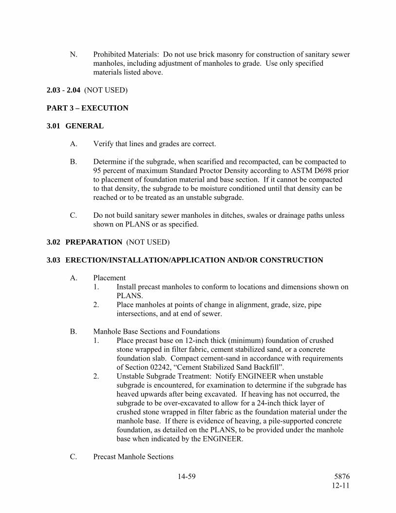
N. Prohibited Materials: Do not use brick masonry for construction of sanitary sewer
manholes, including adjustment of manholes to grade. Use only specified materials listed above.
2.03 - 2.04 (NOT USED) PART 3 – EXECUTION 3.01 GENERAL
A. Verify that lines and grades are correct. B. Determine if the subgrade, when scarified and recompacted, can be compacted to
95 percent of maximum Standard Proctor Density according to ASTM D698 prior to placement of foundation material and base section. If it cannot be compacted to that density, the subgrade to be moisture conditioned until that density can be reached or to be treated as an unstable subgrade.
C. Do not build sanitary sewer manholes in ditches, swales or drainage paths unless
shown on PLANS or as specified. 3.02 PREPARATION (NOT USED) 3.03 ERECTION/INSTALLATION/APPLICATION AND/OR CONSTRUCTION
A. Placement 1. Install precast manholes to conform to locations and dimensions shown on
PLANS. 2. Place manholes at points of change in alignment, grade, size, pipe
intersections, and at end of sewer. B. Manhole Base Sections and Foundations
1. Place precast base on 12-inch thick (minimum) foundation of crushed stone wrapped in filter fabric, cement stabilized sand, or a concrete foundation slab. Compact cement-sand in accordance with requirements of Section 02242, “Cement Stabilized Sand Backfill”.
2. Unstable Subgrade Treatment: Notify ENGINEER when unstable subgrade is encountered, for examination to determine if the subgrade has heaved upwards after being excavated. If heaving has not occurred, the subgrade to be over-excavated to allow for a 24-inch thick layer of crushed stone wrapped in filter fabric as the foundation material under the manhole base. If there is evidence of heaving, a pile-supported concrete foundation, as detailed on the PLANS, to be provided under the manhole base when indicated by the ENGINEER.
C. Precast Manhole Sections

15-59 5876 12-11
1. Install sections, joints and gaskets in accordance with manufacturer’s printed recommendations.
2. Install precast adjustment rings above tops of cones or flat-top sections as required to adjust the finished elevation and to support the manhole frame.
3. Seal any lifting holes with non-shrink grout. 4. Where PVC liners are required, seal joints between sections in accordance
with manufacturer’s recommendations. 5. Do not incorporate manhole steps in manhole sections, unless otherwise
shown on PLANS.
D. Pipe Connections at Manholes 1. Install approved resilient connectors at each pipe entering and exiting
sanitary sewer manholes in accordance with manufacturer’s instructions. 2. Ensure that no concrete, cement stabilized sand, fill, or other rigid material
is allowed to enter the space between the pipe and the edge of the wall opening at and around the resilient connector on either the interior or exterior of the manhole. If necessary, fill the space with a compressible material to guarantee the full flexibility provided by the resilient connector.
3. Where a new manhole is to be constructed on an existing sewer, a rigid joint pipe may be used. Install a waterstop gasket around the existing pipe at the center of the cast-in-place wall. Join ends of split waterstop material at the pipe springline using an adhesive recommended and supplied by the waterstop manufacturer.
4. Test connection for watertight seal before backfilling. E. Inverts for Sanitary Sewers
1. Construct invert channels to provide a smooth flow transition waterway with no disruption of flow at pipe-manhole connections. Conform to the following criteria: a. Slope of Invert Bench: 1 inch per foot minimum; 1½ inches per
foot maximum. b. Depth of Bench to Invert:
(1) Pipes smaller than 15 Inches: One-half of the largest pipe diameter.
(2) Pipes 15 to 24 Inches: Three-fourths of the largest pipe diameter.
(3) Pipes larger than 24 Inches: Equal to the largest pipe diameter.
c. Invert Slope Through Manhole: 0.10-foot drop across manhole with smooth transition to invert through manhole, unless otherwise indicated on PLANS.
2. Form invert channels with concrete if not integral with manhole base section. For direction changes of mains, construct channels tangent to mains with maximum possible radius of curvature. Provide curves for side inlets and smooth invert fillets for flow transition between pipe inverts.

16-59 5876 12-11
F. Drop Connections for Sanitary Sewers
1. Backfill drop assembly with crushed stone wrapped in filter fabric, cement stabilized sand, or Class A concrete to form a solid mass. Extend cement stabilized sand or concrete encasement a minimum of 4 inches outside of bells.
2. Install a drop connection when a sewer line enters a manhole higher than 30 inches above the invert of a manhole.
G. Stubs for Future Connections
1. In manholes, where future connections are indicated on the PLANS, install resilient connectors and pipe stubs with approved watertight plugs.
H. Manhole Frame and Adjustment Rings
1. Combined precast concrete adjustment rings so that the elevation of the installed casting cover matches the pavement surface. Seal between adjustment ring and the precast top section with non-shrink grout; do not use mortar between adjustment rings. Apply a latex-based bonding agent to precast concrete surfaces to be joined with non-shrink grout. Set the cast iron frame on the adjustment ring in a bed of approved sealant. The sealant bed is to consist of two beads of sealant, each bead having minimum dimensions of 1/2-inch high and 3/4-inch wide.
2. For manholes in unpaved areas, top of frame shall be set a minimum of 6 inches above existing ground line unless otherwise indicated on PLANS. In unpaved areas, encase the manhole frame in mortar or non-shrink grout placed flush with the face of the manhole ring and the top edge of the frame. Provide a rounded corner around the perimeter.
I. Backfill
1. Place and compact backfill materials in the area of excavation surrounding manholes in accordance with requirements shown on the PLANS. Provide embedment zone backfill material, as specified for the adjacent utilities, from manhole foundation up to an elevation 12 inches over each pipe connected to the manhole. Provide trench zone backfill, as specified for the adjacent utilities, above the embedment zone backfill.
2. Where rigid joints are used for connecting existing sewers to the manhole, backfill under the existing sewer up to the springline of the pipe with Class B concrete or flowable fill.
3.04 REPAIR/RESTORATION (NOT USED) 3.05 FIELD QUALITY CONTROL
Conduct leakage testing of manholes in accordance with requirements as specified in Paragraph 2.02 J.
3.06 - 3.08 (NOT USED)

17-59 5876 12-11
3.09 PROTECTION
Protect manholes from damage until work has been finally accepted. Repair damage to manholes at no additional cost to the Department.
3.10 SCHEDULES (NOT USED) 3.11 MEASUREMENT AND PAYMENT
A. Unless otherwise indicated, no separate payment for work performed under this Section if noted as such on the PLANS. Include cost of same in the Contract price bid for work of which this is a component part.
B. When indicated in the BID documents, payment for all types of sanitary and
storm sewer manholes are on a unit price basis for each manhole installed. Payment to be made at Contract price bid for the following items as applicable. 1. Pay for “Storm Sewer Manhole (all Depths)” at Contract price bid per
each manhole installed, complete in place. 2. Pay for “Manhole, Sanitary Sewer (all Depths)” at Contract price bid per
each manhole installed, complete in place. 3. Pay for “Manhole with Drop Inlet, Sanitary Sewer (all Depths)” at
contract price bid per each manhole installed, complete in place.
END OF SECTION

18-59 5876 12-11
SECTION 02612
POLYVINYL CHLORIDE (PVC) PRESSURE PIPE 4-INCH THROUGH 16-INCH FOR WATER DISTRIBUTION
PART 1 – GENERAL
1.01 SUMMARY
This Section includes the furnishing, installation, testing, disinfection and placing in service of polyvinyl chloride (PVC) pressure pipe and connecting fittings.
1.02 RELATED REQUIREMENTS
A. Related work as called for on the PLANS or specified in this or other TECHNICAL SPECIFICATIONS.
1.03 REFERENCES
The publications listed below form a part of this specification to the extent referenced. The publications are referred to in the text by basic designation only.
AMERICAN SOCIETY FOR TESTING AND MATERIALS (ASTM)
ASTM D1784 Standard Specification for Rigid Poly (Vinyl Chloride) (PVC) Compounds and Chlorinated Poly (Vinyl Chloride) (CPVC) Compounds
ASTM F477 Standard Specification for Elastomeric Seals (Gaskets) for Joining Plastic Pipe
ASTM F1483 Standard Specification for Oriented Poly (Vinyl Chloride), (PVCO) Pressure Pipe
AMERICAN WATER WORKS ASSOCIATION (AWWA)
AWWA C900 Polyvinyl Chloride (PVC) Pressure Pipe, 4-Inch Through 12-Inch for Water Distribution, Addendum Thereto:
AWWA C909 Molecularly Oriented Polyvinyl Chloride (PVCO) Pressure Pipe, 4-Inch Through 12-Inch for Water Distribution
AWWA C905 Polyvinyl Chloride Water Transmission Pipe, Nominal Diameters 14-Inch Through 36-Inch
NSF INTERNATIONAL (NSF)
NSF 14 Latest Issue Plastic and Plumbing System Components
1.04 - 1.11 (NOT USED)

19-59 5876 12-11
PART 2 – PRODUCTS
2.01 MANUFACTURER(S) (NOT USED)
2.02 MATERIALS
A. Pipe 12-inch or less in diameter to be in accordance with the requirements of ASTM D1784 and AWWA C900 for Polyvinyl Chloride (PVC) Pressure Pipe; and ASTM F1483 and AWWA C909 for Molecularly Oriented Polyvinyl Chloride (PVCO) Pressure Pipe.
B. Pipe greater than 12-inch diameter to be in accordance with ASTM D1784 and AWWA C905 for Polyvinyl Chloride (PVC) Water Transmission Pipe, Nominal Diameters 14-Inch through 36-Inch.
C. Pipe 12-inch or less in diameter to be rated DR25 with CI outside diameter.
D. Pipe greater than 12-inch to be rated DR14 with CI outside diameter.
E. Elastomeric gaskets to be in accordance with the requirements of ASTM F477. The gasket to be the sole element depended upon to make the joint flexible and watertight. The gasket to be a continuous elastomeric ring.
F. Lubricant to be in accordance with the requirements of AWWA C900, C909 or C905 and pipe manufacturer’s recommendations. Lubricant to be suitable for lubricating the parts of the joints in the assembly. The lubricant is not to have any deteriorating effects on the gasket and pipe materials.
2.03 - 2.04 (NOT USED)
PART 3 – EXECUTION
3.01 - 3.02 (NOT USED)
3.03 ERECTION/INSTALLATION/APPLICATION AND/OR CONSTRUCTION
A. Trenching and subsequent backfill operations to be per applicable Specification Section and/or as shown on PLANS. Avoid contact between pipe and compaction equipment. Compaction of haunching, initial backfill, and backfill material to be done in a manner that compaction equipment is not used directly above pipe until sufficient backfill has been placed to ensure that equipment will have no damaging effect on pipe.
B. Joining: Use elastomeric gasket joints, per ASTM F477, providing a watertight seal. Assembly of joints to be per manufacturer’s recommendations.
C. Thrust Blocking: CONTRACTOR is responsible for design of thrust blocking and/or collar.

20-59 5876 12-11
3.04 REPAIR/RESTORATION
Any damage to pipe or over-excavation which is caused by the CONTRACTOR’s activities to be repaired or replaced at no additional cost to the Department.
3.05 FIELD QUALITY CONTROL
A. Hydrostatic Testing: On completion of the installation of the pipeline or in segments as directed by the ENGINEER, hydrostatic testing is to be completed as specified.
B. Disinfection: Disinfection of the installed pipeline and subsequent water quality testing to be as specified.
3.06 - 3.10 (NOT USED)
3.11 MEASUREMENT AND PAYMENT
A. Unless otherwise indicated, no separate payment for work performed under this Section if noted as such on the PLANS. Include cost of same in Contract price bid for work of which this is a component part.
B. When indicated in the BID documents, measure by linear foot from center line of fitting to center line of fitting, exclusive of pipe installed in tunnel construction, special structures, or other special sections, along pipe of size and type installed. If depth of cut is shown on the Contract Bid Item, measure depth at intervals not to exceed 50 feet and at breaks in profile of natural ground from flow line of pipe to natural ground surface over center of pipe. If depth of cut is not shown on Contract Bid Item, no consideration will be made for depth at which pipe is installed. 1. Payment: Pay for pressure pipelines furnished, installed, disinfected,
tested, and measured as stated, at Contract unit price bid for size and type (and depth, if shown on Contract Bid Item) measured.
END OF SECTION
SECTION 02615
POLYVINYL CHLORIDE (PVC) SEWER PIPE AND FITTINGS
PART 1 - GENERAL 1.01 SUMMARY
This Section includes the furnishing, installation of polyvinyl chloride (PVC) sewer pipe and connecting fittings.

21-59 5876 12-11
1.02 RELATED REQUIREMENTS
A. Related work as called for on the PLANS or as specified in this or other TECHNICAL SPECIFICAITONS.
B. Trenching and the subsequent backfilling operations including the pipe zone area
to be in accordance with the applicable Specification Sections and/or as shown on PLANS.
1.03 REFERENCES
The publications listed below form a part of this specification to the extent referenced. The publications are referred to in the text by basic designation only.
AMERICAN SOCIETY FOR TESTING AND MATERIALS (ASTM)
ASTM D2321 Standard Practice for Underground Installation of Thermoplastic
Pipe for Sewers and Other Gravity-Flow Applications ASTM D3034 Standard Specification for Type PSM Poly (Vinyl Chloride) (PVC)
Sewer Pipe and Fittings ASTM D3212 Standard Specification for Joints for Drain and Sewer Plastic Pipes
using Flexible Elastomeric Seals 1.04 - 1.11 (NOT USED) PART 2 - PRODUCTS 2.01 MANUFACTURER(S) (NOT USED) 2.02 MATERIALS
A. Sewer pipe and fittings to be in accordance with the requirements of ASTM D3034. SDR Type to be shown on PLANS.
B. Gaskets to be in accordance with the requirements of ASTM D3212. The gasket
to be the sole element depended upon to make the joint flexible and watertight. The gasket to be a continuous elastomeric ring.
C. Lubricant to be in accordance with the requirements of ASTM D3212. Lubricant
to be suitable for lubricating the parts of the joints in the assembly. The lubricant to not have any deteriorating effects on the gasket and pipe materials.
2.03 - 2.04 (NOT USED)

22-59 5876 12-11
PART 3 - EXECUTION 3.01 - 3.02 (NOT USED) 3.03 ERECTION/INSTALLATION/APPLICATION AND/OR CONSTRUCTION
A. Trenching and subsequent backfill operations excluding backfill in the pipe zone, to be per applicable Specification Section(s) and/or as shown on PLANS.
B. Backfill in Pipe Zone: Backfill pipe and fittings in accordance with ASTM
D2321 except as otherwise shown on PLANS. Note: Initial backfill over pipe to be 12 inches in all cases. Class or embedment (aggregate and sand) materials to be as shown on PLANS for PVC sewer pipe installations. Avoid contact between pipe and compaction equipment. Compaction of haunching, initial backfill, and backfill material to be done in a manner that compaction equipment is not used directly above pipe until sufficient backfill has been placed to ensure that equipment will have no damaging effect on pipe.
C. Joining: Use elastomeric gasket joints, per ASTM D3212, providing a watertight
seal. Assembly of joints to be per manufacturer's recommendations. D. Connections to Manholes and Other Rigid Structures: Manhole couplings
corresponding to size of sewer pipe to be cast directly into a rigid structure such as manhole or manhole base.
3.04 REPAIR/RESTORATION
Any repair or over excavation not authorized by the ENGINEER and which is caused by the CONTRACTOR’s activities to be repaired or replaced at no additional cost to the Department.
3.05 FIELD QUALITY CONTROL
Testing: To be in accordance with PLANS and with Specification Section 02687, “Testing of Installed Piping Systems”.
3.06 - 3.10 (NOT USED) 3.11 MEASUREMENT AND PAYMENT
A. Unless otherwise indicated, no separate measurement or payment for work performed under this Section. Include cost of same in Contract price bid for work of which this is a component part.

23-59 5876 12-11
B. When indicated in the BID documents, measure by linear foot from center of manhole to center of manhole, exclusive of pipe installed in tunnel construction, special structures, or other special sections, along pipe of size and at depth installed. Measure depth at manholes, at intervals not to exceed 50 feet between manholes, and at breaks in the profile of natural ground from flow line of pipe to natural ground surface over center of pipe. 1. Payment: Pay for gravity pipelines, furnished, installed, tested, and
measured as stated, at Contract unit price bid for size and depth measured.
END OF SECTION

24-59 5876 12-11
SECTION 02665 DISINFECTION OF WATER LINES
PART 1 – GENERAL
1.01 SUMMARY
This Section includes the disinfection of newly installed water lines on the initial filling of pipe prior to being placed into service. This Section also includes the disinfection of connections to existing service lines. Water for disinfection to be provided by the CONTRACTOR unless otherwise shown on PLANS.
1.02 RELATED REQUIREMENTS (NOT USED)
1.03 REFERENCES
The Publications listed below form a part of this Specification to the extent referenced. The publications are referred to in the text by basic designation only.
AMERICAN WATER WORKS ASSOCIATION (AWWA)
AWWA C651 1992 Standard for Disinfecting Water Mains
TEXAS COMMISSION ON ENVIRONMENTAL QUALITY (TCEQ) ENVIRONMENTAL QUALITY CHAPTER 290 WATER HYGENE
Sub-chapter F Drinking Water Standards Governing Drinking Water Quality and Reporting Requirements for Public Water Supply Systems Latest Edition thereto
1.04 - 1.05 (NOT USED)
1.06 SUBMITTALS
A. Submit sample and test requirements and include the information as further described under paragraph 3.05 Field Quality Control of this Specification Section.
B. Submit Testing Procedures/Plans as indicated in Appendix A, Chlorine Residual Testing of AWWA C651.
C. Submit Disposal of Heavily Chlorinated Water Procedures as indicated in Appendix B of AWWA C651.
1.07 - 1.11 (NOT USED)
PART 2 – PRODUCTS
2.01 MANUFACTURER(S) (NOT USED)

25-59 5876 12-11
2.02 MATERIALS AND/OR EQUIPMENT
Chlorination agents to be in accordance with AWWA C651.
2.03 - 2.04 (NOT USED)
PART 3 – EXECUTION
3.01 - 3.02 (NOT USED)
3.03 ERECTION/INSTALLATION/APPLICATION AND/OR CONSTRUCTION
A. Disinfecting procedures to be in accordance with the requirements of AWWA C651 and as specified hereinafter. Minimal chlorine dosage to be 50 mg/l.
B. Furnish pump, pipe connections, and necessary apparatus, gauges, and meters. Furnish necessary labor, assistance, and chlorinating agent for disinfection. Prevent admission of contaminated water to previously disinfected lines. If contaminated water is admitted to previously disinfected lines, disinfect those lines at no additional cost to Department.
C. Application of chlorine to be in accordance with AWWA C651 Table 4 for the size pipe indicated.
3.04 REPAIR/RESTORATION (NOT USED)
3.05 FIELD QUALITY CONTROL
A. Samples are to be taken in accordance with AWWA C651.
B. Bacterial analysis and other specific test requirements are to be in accordance with TCEQ Chapter 290 and submitted for final analysis and approval. The ENGINEER is to be present during water purge for the samples required.
C. Acceptance and placement in service will be based on the approved results returned from the TCEQ. If additional tests are required to comply with TCEQ Chapter 290, procedure is to be completed in accordance with paragraph 3.03. Additional testing is to be completed at no additional cost to the Depaertment.
3.06 - 3.10 (NOT USED)
3.11 MEASUREMENT AND PAYMENT
No separate measurement or payment for work performed under this Section. Include cost of same in Contract unit price for other items of which this work is a component.
END OF SECTION

26-59 5876 12-11
SECTION 02687
TESTING OF INSTALLED PIPING SYSTEMS
PART 1 - GENERAL 1.01 DESCRIPTION
A. Scope: Furnish all labor, materials, tools, and equipment, and perform all operations in connection with testing of installed piping systems and appurtenances. B. PLANS show pipe sizes, arrangements, working pressures, and test pressures.
When PLANS lack such information, minimum test pressures specified in Attachment “B” herein to be used.
C. Related Work: Piping materials and installation requirement as called for on
PLANS or specified elsewhere in this or other TECHNICAL SPECIFICATIONS Sections.
PART 2 - PRODUCTS (NOT USED)
PART 3 - EXECUTION 3.01 GENERAL
A. All testing to be conducted in the presence of ENGINEER and/or local reviewing authority. A minimum of 24 hours notice is required prior to commencing tests. Length of piping and sections included in tests to meet with approval of ENGINEER.
B. Water for Testing
1. Except for potable water lines, non-potable water may be used for testing. 2. CONTRACTOR is responsible for conveying and ultimate disposal of
water used for testing. 3. If potable water is used for testing CONTRACTOR is responsible for
metering. 4. Water required to fill new mains for hydrostatic pressure testing,
disinfection, and flushing may be supplied through a temporary connection between the distribution system and the new main, with the ENGINEER’s approval. The temporary connection is to include an appropriate cross-connection control device.
5. All costs associated with re-testing to be borne by CONTRACTOR. C. Furnish all taps, fittings, blind flanges, bulkheads, bracing systems, plugs, and
other devices for use in filling, flushing, and testing.
27-59 5876 12-11
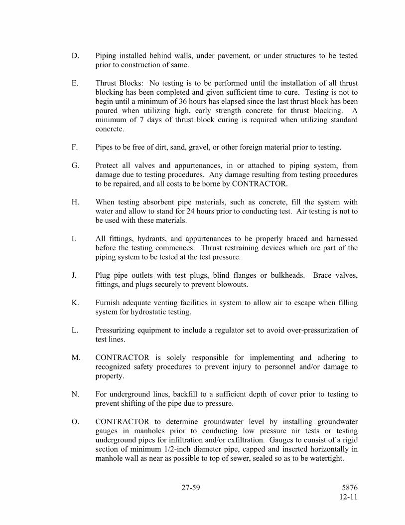
D. Piping installed behind walls, under pavement, or under structures to be tested
prior to construction of same. E. Thrust Blocks: No testing is to be performed until the installation of all thrust
blocking has been completed and given sufficient time to cure. Testing is not to begin until a minimum of 36 hours has elapsed since the last thrust block has been poured when utilizing high, early strength concrete for thrust blocking. A minimum of 7 days of thrust block curing is required when utilizing standard concrete.
F. Pipes to be free of dirt, sand, gravel, or other foreign material prior to testing. G. Protect all valves and appurtenances, in or attached to piping system, from
damage due to testing procedures. Any damage resulting from testing procedures to be repaired, and all costs to be borne by CONTRACTOR.
H. When testing absorbent pipe materials, such as concrete, fill the system with
water and allow to stand for 24 hours prior to conducting test. Air testing is not to be used with these materials.
I. All fittings, hydrants, and appurtenances to be properly braced and harnessed
before the testing commences. Thrust restraining devices which are part of the piping system to be tested at the test pressure.
J. Plug pipe outlets with test plugs, blind flanges or bulkheads. Brace valves,
fittings, and plugs securely to prevent blowouts. K. Furnish adequate venting facilities in system to allow air to escape when filling
system for hydrostatic testing. L. Pressurizing equipment to include a regulator set to avoid over-pressurization of
test lines. M. CONTRACTOR is solely responsible for implementing and adhering to
recognized safety procedures to prevent injury to personnel and/or damage to property.
N. For underground lines, backfill to a sufficient depth of cover prior to testing to
prevent shifting of the pipe due to pressure. O. CONTRACTOR to determine groundwater level by installing groundwater
gauges in manholes prior to conducting low pressure air tests or testing underground pipes for infiltration and/or exfiltration. Gauges to consist of a rigid section of minimum 1/2-inch diameter pipe, capped and inserted horizontally in manhole wall as near as possible to top of sewer, sealed so as to be watertight.

28-59 5876 12-11
Immediately prior to performance of test, groundwater back pressure to be determined by removing pipe cap, blowing air through pipe into ground to clean pipe, then connecting a clear plastic tube to pipe. Clear plastic tube to be held vertically and measurement of height (in feet) of water over invert of pipe to be taken after water has stopped rising. Upon completion of air test, remove groundwater gauge from wall of manhole and permanently close opening with a nonshrinking, noncorrosive grout.
P. Test pressure is not to exceed rated pressure of valves installed in line.
3.02 HYDROSTATIC TESTING
A. Test Pressure: Unless otherwise specified in the test schedule herein or the piping schedule on the PLANS, the following pressure restrictions to apply:
1. Test Pressure a. 150% of the working pressure at the point of testing; or b. 125% of the working pressure at the highest point along the test
section. c. In the event of a conflict between a. and b. above, the greater value
is to apply. 2. For surcharged piping systems, working pressure is defined as the difference in elevation between the lowest point in the piping system and the maximum water surface elevation in the hydraulic structure immediately upstream of the piping system.
3. Test pressure is not to vary by more than plus or minus 5 psi. B. Duration of Pressure Test: Exposed joints to be tested for not less than 2 hours
with no allowable leakage. Covered joints to be tested for a minimum of 6 hours. If leakage at the end of the 6-hour period exceeds the allowable by less than 25%, test to continue for not less than 18 additional hours. For test durations greater than 2 hours, furnish a calibrated pressure recorder to record pressure during test. Reference Paragraph 3.09 for allowable leakage.
C. Pressurization: Each valved section of pipe to be filled with water slowly and the
specified test pressure, based on the elevation of the highest point of the line or section under test and corrected to the elevation of the test gauge, to be applied by means of a pump connected to the pipe. Furnish pump, pipe connections, and necessary apparatus, gauge, volumetric measuring device and meters. Furnish necessary labor and assistance for conducting test, all subject to approval by ENGINEER.
D. Air Removal: Before applying the specified test pressure, air to be expelled
completely from the pipe, valves, and hydrants. If permanent air vents are not located at all high points, CONTRACTOR to install corporation cocks at such points so that the air can be expelled as the line is filled with water. After all the air has been expelled, the corporation cocks to be closed and the test pressure applied. At the conclusion of the pressure test, the corporation cocks to be removed and plugged, or left in place at the discretion of the ENGINEER.
29-59 5876 12-11
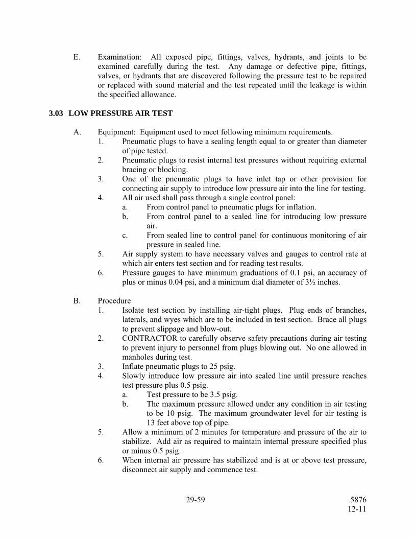
E. Examination: All exposed pipe, fittings, valves, hydrants, and joints to be
examined carefully during the test. Any damage or defective pipe, fittings, valves, or hydrants that are discovered following the pressure test to be repaired or replaced with sound material and the test repeated until the leakage is within the specified allowance.
3.03 LOW PRESSURE AIR TEST
A. Equipment: Equipment used to meet following minimum requirements. 1. Pneumatic plugs to have a sealing length equal to or greater than diameter
of pipe tested. 2. Pneumatic plugs to resist internal test pressures without requiring external
bracing or blocking. 3. One of the pneumatic plugs to have inlet tap or other provision for
connecting air supply to introduce low pressure air into the line for testing. 4. All air used shall pass through a single control panel:
a. From control panel to pneumatic plugs for inflation. b. From control panel to a sealed line for introducing low pressure
air. c. From sealed line to control panel for continuous monitoring of air
pressure in sealed line. 5. Air supply system to have necessary valves and gauges to control rate at
which air enters test section and for reading test results. 6. Pressure gauges to have minimum graduations of 0.1 psi, an accuracy of
plus or minus 0.04 psi, and a minimum dial diameter of 3½ inches. B. Procedure
1. Isolate test section by installing air-tight plugs. Plug ends of branches, laterals, and wyes which are to be included in test section. Brace all plugs to prevent slippage and blow-out.
2. CONTRACTOR to carefully observe safety precautions during air testing to prevent injury to personnel from plugs blowing out. No one allowed in manholes during test.
3. Inflate pneumatic plugs to 25 psig. 4. Slowly introduce low pressure air into sealed line until pressure reaches
test pressure plus 0.5 psig. a. Test pressure to be 3.5 psig. b. The maximum pressure allowed under any condition in air testing
to be 10 psig. The maximum groundwater level for air testing is 13 feet above top of pipe.
5. Allow a minimum of 2 minutes for temperature and pressure of the air to stabilize. Add air as required to maintain internal pressure specified plus or minus 0.5 psig.
6. When internal air pressure has stabilized and is at or above test pressure, disconnect air supply and commence test.

30-59 5876 12-11
Utilizing a stopwatch, record period of time required for pressure to drop 1.0 psig from starting pressure. Following table lists minimum test times for various pipe sizes. If time for pressure to decrease 1.0 psig is less than value in table, then system has failed.
Minimum Test Time
Pipe Size Minutes Seconds 6″ 2 50 8″ 3 56 10″ 4 43 12″ 5 40 15″ 7 5 18″ 8 30 21″ 9 55 24″ 11 20 27″ 12 45 30″ 14 10 36″ 17 0 42″ 19 50 48″ 22 36 54″ 25 16 60″ 27 47
For other sizes, consult with ENGINEER.
7. Test may be discontinued when prescribed minimum test time has been reached, even though 1.0 psig pressure drop has not occurred.
8. Release air from pipe slowly and remove plugs at conclusion of test. 3.04 PIPELINE SETTLEMENT TESTING
A. TV Inspection 1. Pipe to be TV inspected for possible settlement. When air testing has been
used, run water through pipe to permit meaningful observations. Any pipe settlement which causes ponding of water in pipe is an indication of system failure.
2. TV inspection required on all sanitary sewers greater than 30 inches in diameter and all sewers installed with curved alignment.
B. Mandrel Testing: All plastic piping materials used for gravity sewers to be subjected to a 95% mandrel test. Mandrel testing to be completed no sooner than four weeks after backfilling has been completed. A Go-No-Go deflection testing mandrel with a minimum of nine runners to be used for testing.

31-59 5876 12-11
Mandrel to be furnished with proving ring. Dimensions of the mandrel for SDR-35 PVC, to be as shown in Attachment “A” to this Section. For other wall thicknesses, consult ENGINEER. Testing to be as follows:
1. Completely flush line and clean pipe of debris.
2. Install pull rope in section to be tested. 3. Attach pull rope and retrieval rope to mandrel. 4. Insert mandrel in pipe. Remove slack from pull rope and place tape
marker on rope at end of pipe where mandrel will exit. Tape marker to be used to determine mandrel location in line.
5. Using guide pulleys, pull mandrel through line. Use tape marker to determine location of over-deflected sections.
6. All pipe sections failing to pass the mandrel to be removed and reinstalled. 7. Repeat testing until system passes.
3.05 LEAKAGE TESTING FOR PRESSURE PIPELINES
A. Leakage test to be conducted concurrently with hydrostatic pressure tests. B. Leakage Defined: Leakage is defined as the quantity of water that must be
supplied into pipe, or any valved section thereof, to maintain pressure within specified test pressure after air in pipeline has been expelled and pipe has been filled with water and brought to test pressure.
C. Determine rate of leakage at 15-minute intervals by means of volumetric
measurement of makeup water added to maintain test pressure. The test to proceed until the rate of leakage has stabilized or is decreasing below an allowable value, for 3 consecutive 15-minute intervals. After this, test pressure to be maintained for at least another 15 minutes.
D. The allowable leakage for pressure pipelines including surcharged gravity lines
not to exceed the following in gallons per 24 hours per inch of diameter per mile of pipe:
Type of Pipe
Leakage (gallons per 24 hours per
inch of diameter per mile of pipe)
Ductile iron 10 Polyvinyl chloride, thermal plastic or fiberglass with rubber joints
10
Polyvinyl chloride, thermal plastic or fiberglass with solvent-cemented joints, or centrifugally cast fiberglass pipe and fittings
0
Concrete with steel and rubber joints 10

32-59 5876 12-11
Type of Pipe
Leakage (gallons per 24 hours per
inch of diameter per mile of pipe)
Steel with welded joints 0 Steel with harnessed joints 10 Wrought steel 0 Copper 0 All piping inside structures 0
Regardless of the above allowable leakage, any visible leaks detected to be permanently stopped.
3.06 – 3.10 (NOT USED) 3.11 MEASUREMENT AND PAYMENT
No separate measurement or payment for work performed under this Section. Include cost of same in Contract price bid for work of which this is a component part.

33-59 5876 12-11
ATTACHMENT “A”
DEFLECTION TESTING MANDREL SCALE: NTS

34-59 5876 12-11
ATTACHMENT “B”
Service Size Required Tests Test Pressure Duration RemarksGravity A. Storm Sewer All Visual None N/A B. Sanitary Sewer All Low Pressure
Air + TV + Mandrel
See Text See Text
C. Surcharged All Hydrostatic 150% of system pressure
2 Hrs. (min.)
Above Ground A. Aboveground All Hydrostatic &
Leakage 150% of system pressure (100 psi min.)
2 Hrs. (min.)
Underground Pressure Piping
All Hydrostatic & Leakage
Waterlines: 150 psi Pump discharge: 150% of pump shut-off head (100 psi min.)
2 Hrs. (min.)
Tank Fill & Drain All Hydrostatic & Leakage
150% of tank head 2 Hrs. (min.)
No leaks allowed
Open-Ended Piping
Up to 48″ Hydrostatic & Leakage
25 psi If >48″, consult ENGINEER
1 Hr. (min.)
END OF SECTION

35-59 5876 12-11
SECTION 02770
CONSTRUCTION OF UNDERGROUND LINES
PART 1 – GENERAL
1.01 SUMMARY
This Section includes furnishing all equipment, tools, supplies, labor and supervision required for construction of underground pipelines.
1.02 RELATED REQUIREMENTS
A. Related work as called for on the PLANS or specified in this or other TECHNICAL SPECIFICATIONS.
B. Testing of the completed work being performed under this Section to be in accordance with the related Specification Section included with these Contract Documents for the specific pipe being installed and/or as shown on the PLANS.
C. Backfill in the pipe zone and above the pipe zone to be in accordance with details shown on PLANS.
D. Concrete, if required, to be in accordance with the specific concrete specification included with these Contract Documents and/or as shown on PLANS.
E. Trench Shoring to be in accordance with the requirements specified in Specification Section 02161 Trench Excavation and Shoring Plan and/or as shown on PLANS.
1.03 REFERENCES
The Publications listed below form a part of this Specification to the extent referenced. The publications are referred to in the text by basic designation only.
AMERICAN SOCIETY OF TESTING AND MATERIALS (ASTM)
ASTM D698 Test Method for Laboratory Compaction Characteristics of Soil Using Standard Effort (12,400 ft-lb/ft [600 kN-m/m])
1.04 - 1.11 (NOT USED)
PART 2 – PRODUCTS (NOT USED)
PART 3 – EXECUTION
3.01 - 3.02 (NOT USED)
36-59 5876 12-11
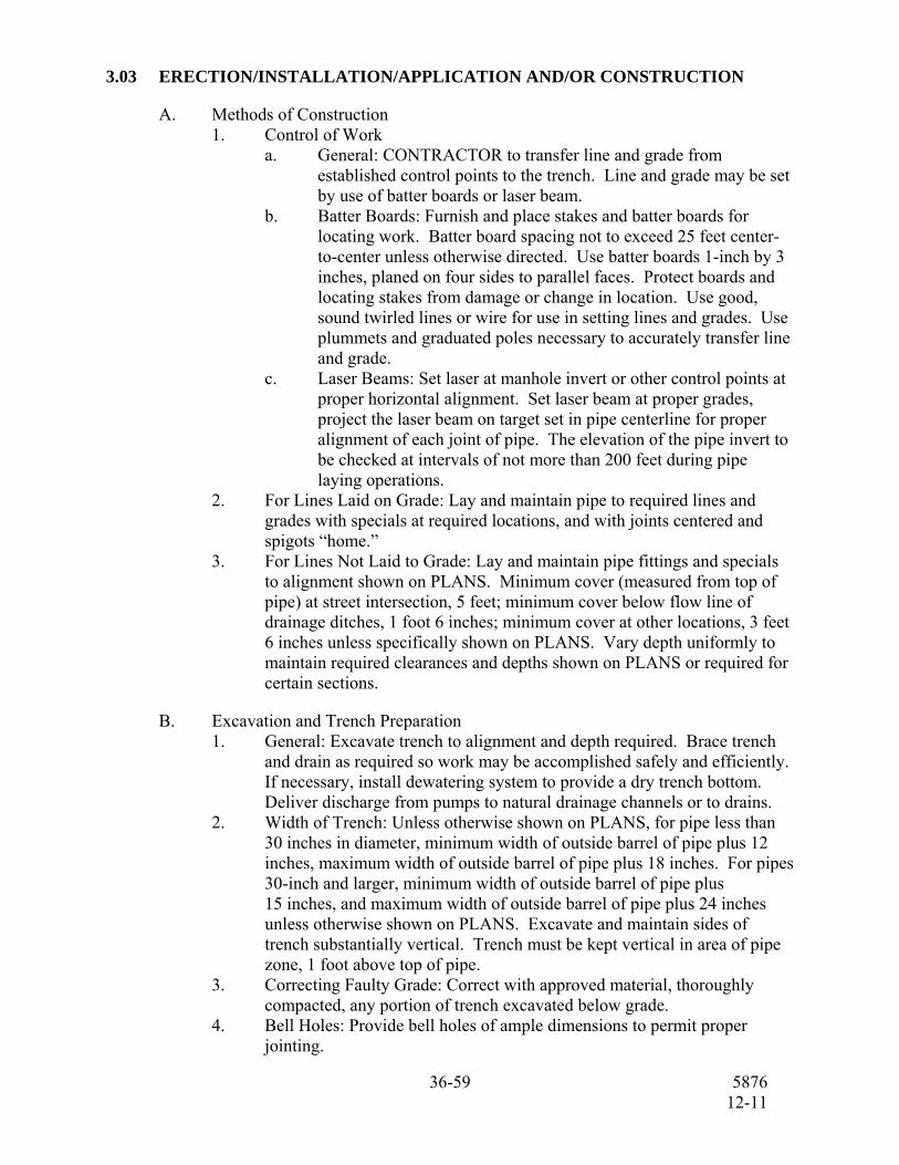
3.03 ERECTION/INSTALLATION/APPLICATION AND/OR CONSTRUCTION
A. Methods of Construction 1. Control of Work
a. General: CONTRACTOR to transfer line and grade from established control points to the trench. Line and grade may be set by use of batter boards or laser beam.
b. Batter Boards: Furnish and place stakes and batter boards for locating work. Batter board spacing not to exceed 25 feet center-to-center unless otherwise directed. Use batter boards 1-inch by 3 inches, planed on four sides to parallel faces. Protect boards and locating stakes from damage or change in location. Use good, sound twirled lines or wire for use in setting lines and grades. Use plummets and graduated poles necessary to accurately transfer line and grade.
c. Laser Beams: Set laser at manhole invert or other control points at proper horizontal alignment. Set laser beam at proper grades, project the laser beam on target set in pipe centerline for proper alignment of each joint of pipe. The elevation of the pipe invert to be checked at intervals of not more than 200 feet during pipe laying operations.
2. For Lines Laid on Grade: Lay and maintain pipe to required lines and grades with specials at required locations, and with joints centered and spigots “home.”
3. For Lines Not Laid to Grade: Lay and maintain pipe fittings and specials to alignment shown on PLANS. Minimum cover (measured from top of pipe) at street intersection, 5 feet; minimum cover below flow line of drainage ditches, 1 foot 6 inches; minimum cover at other locations, 3 feet 6 inches unless specifically shown on PLANS. Vary depth uniformly to maintain required clearances and depths shown on PLANS or required for certain sections.
B. Excavation and Trench Preparation 1. General: Excavate trench to alignment and depth required. Brace trench
and drain as required so work may be accomplished safely and efficiently. If necessary, install dewatering system to provide a dry trench bottom. Deliver discharge from pumps to natural drainage channels or to drains.
2. Width of Trench: Unless otherwise shown on PLANS, for pipe less than 30 inches in diameter, minimum width of outside barrel of pipe plus 12 inches, maximum width of outside barrel of pipe plus 18 inches. For pipes 30-inch and larger, minimum width of outside barrel of pipe plus 15 inches, and maximum width of outside barrel of pipe plus 24 inches unless otherwise shown on PLANS. Excavate and maintain sides of trench substantially vertical. Trench must be kept vertical in area of pipe zone, 1 foot above top of pipe.
3. Correcting Faulty Grade: Correct with approved material, thoroughly compacted, any portion of trench excavated below grade.
4. Bell Holes: Provide bell holes of ample dimensions to permit proper jointing.

37-59 5876 12-11
5. Braced and Sheeted Trenches: Sheet and brace excavations in accordance
with OSHA requirements wherever necessary to prevent caving. Increase trench width as required for sheeting. Sheeting not required to be left in place, cannot be pulled until pipe has been laid and backfill compacted to depth of 2 feet over pipe. Sheet and brace in accordance with Specification Section 02161 Trench Excavation and Shoring Safety Plan.
6. Care of Surface Material for Reuse: Keep surface material approved for reuse separate from general excavation material.
7. Manner of Stockpiling Excavated Material: Stockpile excavated material so as not to endanger work or cause interference with public streets and driveways. Keep drainage channels clear or provide other satisfactory means for drainage.
8. Trenching by Machine or by Hand: Unless otherwise specifically required, CONTRACTOR may use backhoe or trenching machine except where hand methods must be employed to avoid damage to existing structures above or below ground, or where hand excavation is indicated on the PLANS.
9. Open Trench: The ENGINEER may limit amount of trench opened or partially opened at any time in advance of completed pipe laying operation, and amount of trench left unfilled. Open no more than 500 feet of trench on any street at one time. Keep streets open where possible.
10. Disposition of Defective Materials: Remove rejected backfill materials from excavation operations and dispose of off jobsite at CONTRACTOR’s expense with no additional cost to the Department.
C. Pipe Handling 1. Handling and Storage: Unload pipe, fittings, and other accessories at point
of delivery; haul to and distribute at site of project. Load and unload materials by use of hoists, skids, or other approved means to avoid damage. Distribute for convenient laying and to cause minimum inconvenience to public.
2. Inspection: Before lowering and while suspended, inspect pipe for defects. 3. Pipe Kept Clean: Remove foreign matter from pipe and keep clean by
approved methods during and after laying.
D. Pipe Laying 1. Unsuitable Conditions for Laying Pipe: No pipe is to be laid in water or
when trench condition or weather is unsuitable for such work unless specifically approved by ENGINEER.
2. Nonpressure Concrete and Vitrified Clay Pipe: Lay pipe with ends abutting and true to line and grade. Fit and lay pipe to form smooth and uniform invert. Clean sockets prior to lowering into trench. Commence laying of pipe at lowest point so that spigot ends point in direction of flow.
3. Ductile Iron Pipe: Lay ductile iron pipe on firm bedding with spigot ends pointing in the direction of flow for a gravity system.

38-59 5876 12-11
4. Other Pipe: Lay other types of pipe in accordance with approved manufacturers instructions and with applicable provisions of this Specification Section and/or as shown on PLANS.
5. Cutting Pipe: Cut ductile iron pipe with wheel-type cutters or cold chisel.
Flame cutting of ductile iron pipe is not allowed. Make cuts in a neat and workmanlike manner without damage to pipe and so as to leave a smooth end at right angles to axis of pipe. Field cutting of Polyvinyl Chloride pipe to be per pipe manufacturer’s recommendations. Field cutting of concrete pressure pipe is not permitted.
6. Deflection of Pipe Joints: Obtain approval of degree of deflection whenever necessary to deflect from straight line. Where necessary to make major deflection in concrete pressure pipe, use sections of pipe with beveled ends for deflection not greater than 5 degrees. For deflection greater than 5 degrees, use fabricated fittings for concrete pressure pipe and use ductile iron fittings for PVC pressure pipe. Minor deflections may be obtained in pipe joints.
7. Temporary Plug: When pipe laying operation is halted, seal open end of pipe with temporary plug. Plug to remain in place until pipe laying operation commences again. Pipe plug to be blocked as not to allow entry by animal or human elements.
8. Field Assistance: Manufacturer of concrete pressure pipe to furnish field representative to assist, as directed by the ENGINEER, and advise on construction problems which might arise.
E. Plugging Dead Ends: Insert standard plug into bells of all dead ends of pipe.
F. Concrete Blocking: Provide thrust blocking (pipe blocking) for pressure pipelines at all bends, tees, points where reducers or changes in pipe diameter occurs, fire hydrants or flushing valves, and all plugged openings. A combination of thrust blocking and pipe restrained joints may be used. Place blocking against solid ground, with area of bearing on pipe and on ground in each instance as required for pipe test pressure. Place blocking so that all joints will be accessible for repair. For gravity pipelines, place a minimum of 6 inches of concrete on all sides of pipe for encasing, embedding, or blocking where indicated on PLANS.
G. Backfilling 1. Time of Backfilling: As soon as practicable after completion of laying and
jointing pipe, backfill trench. Complete backfilled trench not more than 200 feet behind pipe laying operations.
2. Materials: As shown on PLANS. 3. Deficiency of Backfill: Supply any deficiency in quantity of materials for
backfilling trenches or for filling depressions caused by settlement.

39-59 5876 12-11
3.04 REPAIR/RESTORATION
Replace or repair sidewalks, driveway culverts, inlets, curbing, gutters, shrubbery, trees, fences, sod, and other like obstructions removed or disturbed, to condition equivalent to that existing prior to commencement of this work.
Use concrete having compressive strength in 28 days of not less than 3,000 pounds per square inch in the replacement of curbing, gutters, inlets, and sidewalks. Use reasonable care in removal and replacement of shrubbery and trees designated to be replaced at original locations. Where at all possible, ditch alignment will be such as to minimize this work. Where tree or shrub deemed sufficiently valuable to save is encountered in excavation, ball in burlap, set aside in wet sand or puddling pit, and later reset as required. CONTRACTOR not held responsible for subsequent care of plant. Restoration of asphalt-topped flexible base and concrete streets as specified under other Specification Sections.
3.05 - 3.06 (NOT USED)
3.07 CLEANUP
Remove from site of work, and from public and private property, temporary structures, rubbish, and waste materials, including excess excavated materials. Complete clean up not greater than 2,000 feet behind pipe laying operation. Pipe laying operation to be suspended temporarily if complete clean up is further behind than 2,000 feet.
3.08 - 3.10 (NOT USED)
3.11 MEASUREMENT AND PAYMENT
No separate measurement or payment for work performed under this Section. Include cost of same in Contract price bid for work of which this is a component part.
END OF SECTION

40-59 5876 12-11
SECTION 15062
DUCTILE IRON PIPE AND CAST IRON AND DUCTILE IRON FITTINGS
PART 1 - GENERAL 1.01 SUMMARY
This Section includes furnishing ductile iron piping three inches and larger for buried and exposed systems. Soil pipe and fittings are specified in other Specification Sections.
1.02 RELATED REQUIREMENTS
A. Soil pipe and fittings not under this Specification Section. B. PLANS show pipe class, thickness class, type joints, and service pressure. C. Other related work as called for on PLANS or specified elsewhere in this or other
TECHNICAL SPECIFICATION Sections. 1.03 REFERENCES
The publications listed below form a part of this Specification to the extent referenced. The publications are referred to in the text by basic designation only.
AMERICAN NATIONAL STANDARDS INSTITUTE (ANSI)
ANSI B18.2.1 Square and Hex Bolts and Screws (Inch Series) ANSI B18.2.2 Square and Hex Nuts (Inch Series)
AMERICAN SOCIETY FOR TESTING AND MATERIALS (ASTM) ASTM A307 Standard Specification for Carbon Steel Bolts and Studs,
60,000 psi Tensile Strength
AMERICAN WATER WORKS ASSOCIATION (AWWA) AWWA C104 Cement-Mortar Lining for Ductile-Iron Pipe and Fittings for Water AWWA C105 Polyethylene Encasement for Ductile Iron Pipe Systems AWWA C110 Ductile-Iron and Gray-Iron Fittings, 3-inch Through 48-inch
(75 mm Through 1200 mm), for Water and Other Liquids AWWA C111 Rubber-Gasket Joints for Ductile-Iron Pressure Pipe and Fittings

41-59 5876 12-11
AWWA C115 Flanged Ductile-Iron Pipe with Threaded Flanges AWWA C150 Thickness Design of Ductile-Iron Pipe AWWA C151 Ductile-Iron Pipe, Centrifugally Cast, for Water
1.04 - 1.05 (NOT USED) 1.06 SUBMITTALS
A. Furnish in accordance with Specification Section 01300, “Submittals”. In addition to the items specified in Section 01300 “Submittals”, furnish the following: 1. Detailed installation drawings for piping. 2. Manufacturer’s descriptive literature for mechanical couplings,
mechanical flange adapters, and restrained flange adapters. 3. Certified test reports for threaded-on flanged pipe in for shop testing
required. 4. Certification per Paragraph 1.07.
1.07 QUALITY ASSURANCE
A. Certification: 1. Pipe used in domestic water distribution systems to have Underwriters’ label and
be acceptable to local and state authorities without penalty. 2. Furnish sworn statement that inspection and all tests have been made and meet the
requirements of AWWA C151.
1.08 DELIVERY, STORAGE AND HANDLING
A. Shipping: 1. Piping with flanged ends to be protected with blank wooden or fiberboard
flange protectors. Backing flanges are to be secured to the pipe ends. 2. Pipe spools to loaded and blocked and lagged as necessary to ensure
protection against damage during shipping. 3. Loose parts (couplings, nuts and bolts, gaskets, etc.) are to be shipped in crates
that are clearly marked as to contents. B. Handling and Unloading:
1. Unload and handle piping in accordance with pipe manufacturer’s instructions. 2. Transfer of pipe to be accomplished utilizing nylon straps or steel cables. 3. Exercise extra care when handling flanged pieces due to the additional
loads imparted by the flanges. (Insert blocking or other means to support the flanges independently of the pipe to prevent the weight of the flange from distorting the pipe.)
4. Maintain plugs and flange protectors in openings to protect the pipe.

42-59 5876 12-11
5. Do not dump piping off of transport vehicle. Any damaged, chipped, or cracked fittings or pipe to be replaced at CONTRACTOR’s expense.
C. Storage:
1. Store in an area that will avoid damage due to traffic. 2. Exposure to normal weather conditions is acceptable; however, avoid
contact with other materials. 3. Store at job site on 4″ × 4″ blocking at 6′ spacing. Piping may be stacked
a maximum of three rows high as long as 4″ high spacers are used on 6′ centers.
4. Keep interior of piping free of all foreign matter. 1.09 - 1.11 (NOT USED) PART 2 - PRODUCTS 2.01 MANUFACTURER(S)
A. Pipe: 1. American Cast Iron Pipe Co. 2. McWane Incorporated 3. U.S. Pipe & Foundry
B. Fittings:
1. American Cast Iron Pipe Co. 2. McWane Incorporated 3. U.S. Pipe & Foundry Co. 4. Tyler Pipe 5. Griffin Pipe
2.02 MATERIALS AND/OR EQUIPMENT
A. General: Fabrication dimensions and accuracy of fabrication are responsibility of CONTRACTOR.
B. Pipe:
1. Ductile Iron: Per AWWA C151. 2. Thickness Class:
a. Aboveground Lines: As shown on PLANS and minimum for flanged pipe per AWWA C115, Table 15.2.
b. Underground Lines: As shown on PLANS, but not less than that indicated within AWWA C150 for internal pressure and depth shown on PLANS.
C. Fittings, Flanges, and Joint Material:
1. Fittings: Per AWWA C110 and C111. 2. Threaded-On Flanges: Per AWWA C115. Use ductile flanges on ductile
fittings and cast iron flanges on cast iron fittings. 3. Nonflanged Joint Material

43-59 5876 12-11
a. Rubber Gaskets for Water and Sewage Service: Per AWWA C111.
b. Rubber Gaskets for Diffused Air Systems (10 psi and 210°F Service): EPDM.
D. Restrained Joints:
1. Restrained Joint Pipe: a. Pipes 16” and less: Joints to be restrained by Mega-Lug, by
EBAA Iron, Inc. or equal by Ford Meter Box Co. Provide Mega-Lug Series 1100 and mechanical joint pipe and fittings, or equal by Ford Meter Box Co. Provide Mega-Lug Series 1700, or equal by Ford Meter Box Co. for push on joints.
b. Pipes greater than 16”: Provide one of the following joint restraint systems: 1) Flex-ring or Lock ring by American Cast Iron Pipe Co. 2) TR Flex by U.S. Pipe Co. 3) Super-Lock by Clow Corp 4) Approved equal; locking gaskets not allowed.
E. Gaskets: 1. For water and sewage, use rubber gasket conforming to the Appendix in AWWA
C115. 2. For air service, use 1/8-inch full-face EPDM gaskets, factory cut and
conforming to AWWA C111. F. Bolts and Nuts:
1. Aboveground: a. Hex head bolts and nuts:
1) Bolts per ANSI B18.2.1. 2) Nuts per ANSI B18.2.2.
b. Number, size, and length per Table 15.2 of AWWA C115. c. Material: Low carbon steel per ASTM A307. d. Use studs with nuts on each end for pipe sizes 54″ and larger.
2. Underground: a. Tee-head bolts and hexagonal nuts per AWWA C111. b. Number, size, and length per Table 11.1 of AWWA C111.
c. Material: Low alloy steel or high strength cast iron in accordance with AWWA C111.
G. Exterior Coating:
1. Buried Pipe and Fittings: Bituminous coated, not less than 1 mil thick. 2. Exposed Pipe and Fittings: Per applicable Specification Section.
Bituminous coated pipe and fittings will not be allowed. H. Interior Lining (pipe and fittings):
1. Air Service: Unlined. 2. Water Service: Cement mortar lined per AWWA C104/A21.4. 3. Sewage Service:
a. Interior lining for ductile iron sewer pipe to conform to manufacturer’s recommendations.
44-59 5876 12-11
b. Minimum lining thickness to be 40 mils regardless of material recommended.
c. Acceptable lining materials are:
1) “Corropipe II Wasteliner” by Madison Chemical Industries.
2) “Polythane” by Madison Chemical Industries.
3) “Protecto 401” ceramic epoxy by Vulcan Group.
4) “SP-2000W” by Superior Environmental Products.
5) “SewPerCoat” by La Farge Calcium Aluminates.
I. Encasement for Buried Pipe and Fittings: Polyethylene encasement in accordance
with AWWA C105. J. Mechanical Couplings: Dresser Style 38, long sleeve unless shown otherwise;
equivalent by Smith-Blair or Baker. Harness when required for thrust restraint. K. Flanged Coupling Adapters: Dresser Style 127 (2″-12″), Dresser Style 128 (14″-
96″), equivalent by Smith Blair or equal. L. Restrained Flanged Coupling Adapters: EBAA Iron Series 2100 or equal by Ford
Meter Box Co. M. Wall Pipes: Unless otherwise shown on PLANS, wall pipes to be cast or ductile
iron with an intermediate wall collar. End connections to be as shown on PLANS.
2.03 FABRICATION
A. Flanged Pipe 1. Threaded-On Flanged Pipe: 2. Shop thread, machine tight, and face in machine shop equipped for this
type work and conforming to the requirements of AWWA C115. 2.04 SOURCE QUALITY CONTROL A. Threaded-On Flanged Pipe: Shop test, hydrostatically, each flanged pipe piece at
150 psig.
PART 3 - EXECUTION 3.01 - 3.02 (NOT USED) 3.03 ERECTION/INSTALLATION/APPLICATION AND/OR CONSTRUCTION
A. Installation: Per applicable Specification Section.

45-59 5876 12-11
3.04 - 3.10 (NOT USED) 3.11 MEASUREMENT AND PAYMENT
A. Unless otherwise indicated, no separate measurement or payment for work performed under this Section. Include cost of same in Contract price bid for work of which this is a component part.
B. Pressure Pipelines: When indicated in the BID documents, measure by linear foot
from center line of fitting to center line of fitting, exclusive of pipe installed in tunnel construction, special structures, or other special sections, along pipe of size and type installed. If depth of cut is shown on the Contract Bid Item, measure depth at intervals not to exceed 50 feet and at breaks in profile of natural ground from flow line of pipe to natural ground surface over center of pipe. If depth of cut is not shown on Contract Bid Item, no consideration will be made for depth at which pipe is installed. 1. Payment: Pay for pressure pipelines furnished, installed, disinfected,
tested, and measured as stated, at Contract unit price bid for size and type (and depth, if shown on Contract Bid Item) measured.
C. Gravity Pipelines: When indicated in the BID documents, measure by linear foot
from center of manhole to center of manhole, exclusive of pipe installed in tunnel construction, special structures, or other special sections, along pipe of size and at depth installed. Measure depth at manholes, at intervals not to exceed 50 feet between manholes, and at breaks in the profile of natural ground from flow line of pipe to natural ground surface over center of pipe. 1. Payment: Pay for gravity pipelines, furnished, installed, tested, and
measured as stated, at Contract unit price bid for size and depth measured.
END OF SECTION

46-59 5876 12-11
SECTION 15063
INSTALLATION OF DUCTILE IRON PIPING
PART 1 - GENERAL 1.01 SUMMARY
This Section includes all work necessary to install ductile iron piping as specified herein and as shown on the PLANS.
1.02 RELATED REQUIREMENTS
A. PLANS show sizes, elevations, arrangements, special encasement, and specials. B. Other related work as called for on PLANS or specified elsewhere in this or other
TECHNICAL SPECIFICATION Sections. 1.03 REFERENCES
The publications listed below form a part of this Specification to the extent referenced. The publications are referred to in the text by basic designation only.
AMERICAN SOCIETY FOR TESTING AND MATERIALS (ASTM)
ASTM D698 Test Method for Laboratory Compaction Characteristics of Soil Using Standard Effort
AMERICAN WATER WORKS ASSOCIATION (AWWA) AWWA C105 Polyethylene Encasement for Ductile-Iron Pipe Systems
1.04 - 1.10 (NOT USED) 1.11 SCHEDULING
A. Slab, Floor, Wall and Roof Penetrations: 1. Order wall pipes and sleeves sufficiently early to ensure they are available
for placement in concrete forms. 2. Verify size and location of building and structure penetrations before
forming and placing concrete.

47-59 5876 12-11
PART 2 - PRODUCTS 2.01 PIPE MARKING TAPE
A. Material: Inert polyethylene plastic impervious to known alkalis, acids, chemical reagents, and solvents likely to be encountered in soil.
B. Thickness: Minimum 4 mils. C. Width: 12 inches. D. Color: In accordance with APWA Uniform Color Code for Temporary Marking
of Underground Utility Locations. E. Identifying Lettering: Minimum 1-inch high, permanent black lettering imprinted
continuously over entire length. F. Manufacturers and Models:
1. Reef Industries, Terra Tape. 2. Allen, Markline.
PART 3 - EXECUTION 3.01 GENERAL
A. Examination - Verification of Existing Pipe and Penetrations: 1. Prior to ordering materials, expose all existing pipes which are to be
connected to new pipelines. 2. Verify the size, material, joint types, elevation, horizontal location, and
pipe service of existing pipes. 3. Inspect size and location of structure penetrations to verify adequacy of
wall pipes, sleeves, and other openings before installing connecting pipes. B. Preparation - New Pipe and Fittings:
1. Inspect before exposed pipe or fitting is installed or buried pipe or fitting is lowered into the trench.
2. Clean ends of pipe thoroughly, remove foreign matter and dirt from inside of pipe, and keep clean during and after installation.
C. Coatings:
1. Install exterior protective coating on all pipes as specified in other Specification Sections.
2. Color-code and label non-submerged piping per applicable Specification Section.
3. Damaged Internal Coatings: Repair damaged areas in field with material equal to original coating.

48-59 5876 12-11
D. Valves: Locate where shown on the PLANS and install per applicable Specification Section.
E. Vents and Drains: Vent the high points and drain the low points of pipelines. F. Wall Pipes: Provide wall pipes with thrust collar for all penetrations through
concrete walls, floors, slabs, or roofs that are to be watertight unless otherwise specified or shown on PLANS.
3.02 JOINTING PIPE
A. Bell and Spigot Boltless, Gasketed, Joints: 1. Preparation of Pipe Ends: Remove from bell and spigot ends all lumps,
blisters, excess coal-tar coating, oil, grease, and foreign matter, then wire brush and wipe clean and dry before laying pipe.
2. Installation of Ring Gasket: Wipe gasket seat in socket with clean dry cloth. Place gasket with large end entering first. Spring gasket into seat in bell so that groove fits over head in seat. Apply thin film of lubricant to inside surface of gasket. Lubricant to be furnished by pipe manufacturer to ensure compatibility with any special coatings.
3. Setting Spigot: Align spigot with bell and start into bell so that it contacts gasket. Apply lubricant to engaging surface of spigot if necessary. Pipe 6″ and smaller may be driven with a bar lever on end of pipe. For larger pipe, use only approved ratchet-type jacking tool to pull pipe “home”.
B. Mechanical Joints:
1. Wash socket and plain end with soapy water, then slip gland and gasket over plain end. Face small side of gasket and lip of gland to bell.
2. Paint gasket with soapy water. 3. Push gasket into position, being sure it is evenly seated in socket. 4. Slide gland into position, insert bolts, and run nuts up finger-tight. 5. Tighten bolts to uniform tightness with ratchet wrench. First tighten
bottom bolt, then top, and on around in sequence of 180 apart. C. Flanged:
1. Wire brush flange and clean inside of pipe before placing gasket. 2. Setting Gasket: If non-graphite gaskets are used, apply graphite and water
solution to gasket before placing on flange. 3. Tightening Bolts: After initial alignment, place flange bolts with all heads
in the same direction. Tighten flange bolts, each in turn, at a uniform rate around joint until all are tight.
D. Restrained Flange Adapter Joints:
1. Use only when shown on PLANS or authorized by ENGINEER. 2. Install in strict accordance with manufacturers printed instructions and as
specified above. E. Special Jointing Procedures:

49-59 5876 12-11
1. Connections to Other Pipe Materials: Make connection using coupling approved by ENGINEER with appropriate transition gaskets.
3.03 UNDERGROUND INSTALLATION
A. General: 1. Lay pipe and fittings in conformance with manufacturer’s instructions and
alignment and elevations shown. 2. Provide all special tools and devices, such as special jacks, chokers, and
similar items required for proper installation. 3. Use pipe joints lubricant as specified; no substitutions will be permitted. 4. Do not lay pipe in water or when, in the opinion of the ENGINEER,
trench conditions are unsuitable. 5. Prevent uplift and floating of pipe prior to backfilling. Prevent foreign
material from entering pipe at all times during placement. B. Excavation and Preparation of Trench:
1. Geometry: Maximum width per detail on PLANS. 2. Brace trench and drain as necessary to accomplish work safely and
efficiently as defined by CONTRACTOR’s Trench Safety Plan. 3. Dewater trench as necessary by pumping, well pointing, or other means to
keep trench clear of water. Deliver discharge from pumps to natural drainage ditches or to drains. Attain discharge permit if required at no additional cost to Department.
4. Grade trench bottom to line and grade to which pipe is to be laid, with proper allowance for pipe thickness and pipe base material.
5. Remove hard spots that would prevent a uniform thickness of base or uniform pressure on the pipe barrel.
6. Place pipe base material to proper grade for full width and length of trench. Minimum depth of pipe base below barrel of pipe to be as shown on Detail on PLANS.
7. Excavate bell holes at each joint to permit proper assembly and visual feeler gauge inspection of the entire joint.
8. If trench has been excavated below the required depth for pipe base placement without approval by ENGINEER, fill excess depth to proper subgrade with pipe base specified herein, at the CONTRACTOR’s sole expense.
C. Alignment and Grade:
1. To Grade: As shown with joints centered and spigots home. 2. Not to Grade: Minimum depth of cover 36-inches under finished grade;
18-inches under flow lines of drainage ditches; depth of cover at other locations as shown on PLANS.
3. Correcting Faulty Grade: Correct any part of trench excavated below grade with approved, thoroughly compacted material.
4. Do not deviate more than 1 inch from line or ¼-inch from grade for gravity piping.
5. Measure for grade at the pipe invert, not at the top of the pipe.

50-59 5876 12-11
6. Before laying each section of the pipe, check the grade with a straightedge and correct any irregularities found.
D. Pipe Handling and Laying:
1. Care: Load and unload by use of approved hoists, skids, or other approved means to avoid damage. Keep interior of pipe free of foreign matter.
2. Inspection: Before lowering pipe into trench, inspect pipe for defects. Replace defective joints, fittings, pipe, or coatings.
3. Apply 8-mil polyethylene encasement in accordance with AWWA C105 to all cast iron and ductile iron piping, including fittings and valves.
4. Laying: a. Lay pipe upgrade with bell ends facing direction of laying. b. After a section of pipe has been lowered into the prepared trench,
clean the end of the pipe to be joined, the inside of the joint, and the rubber ring immediately before joining the pipe.
c. Do not block under pipe. d. Do not lay pipe in water. e. Lay pipe only when impending weather conditions will not
endanger quality of workmanship or materials. f. Check gasket position with feeler gauge furnished by the pipe
manufacturer to assure proper seating. Use feeler gauge of proper size, type and shape during installation for each type of pipe furnished.
5. Close and block the open end of the last laid section of pipe to prevent entry of foreign material or creep of the gasketed joints, at all times when laying operations are not in progress, at the close of the day’s work, or when the workers are absent from the job.
6. Deflection of Joints: a. PLANS indicate minor changes in slope and direction without
corresponding fittings. Accommodate changes by deflecting joints. Standard bends may be required to conform to manufacturer’s allowable deflection and the following requirements.
b. Deflect pipe at joints for pipelines using unsymmetrical closure of spigot into bell.
c. Maximum Deflection: 90 percent of maximum deflection recommended by pipe manufacturer for restrained joint pipe, 50 percent for all other joints.
d. Conform to lines and grades on PLANS. Misalignment at point of intersection (PI) of up to 1 foot is allowable provide that line and grade is re-established within 60 feet of PI.
e. Record deflections and/or standard fittings on As-Built drawings. f. Use one of the following methods if joint deflection of standard pipe lengths will not accommodate horizontal or vertical curves in alignment:
1) Shorter pipe lengths. 2) Standard bends.
7. After the joint has been made, check pipe for alignment and grade.

51-59 5876 12-11
8. Valve Boxes and Valves: Set valves and boxes plumb and centered. Provide firm support by tamping selected material as directed. Set top of boxes at finished grade unless directed otherwise.
E. Backfill in the Pipe Zone (Unless Otherwise Noted on PLANS):
1. The pipe zone includes the full width of the excavated trench from the bottom of the trench to a level 12 inches above the top outside surface of the pipe barrel.
2. Deposit select backfill material in the trench simultaneously on both sides of pipe for the full width of trench in horizontal lifts not exceeding 8 inches uncompacted thickness. a. Work the material under the haunches of the pipe by slicing with a
shovel. b. Moisten backfill and compact with tamping bars and/or mechanical
compactors. c. Compact material at the sides of the pipe with vibratory plate
compactors to 95 percent of the maximum density in accordance with ASTM D698.
d. Do not operate the vibratory compactor over the top of the pipe until the full depth of the pipe zone material has been placed.
e. Do not use impact type compactors for compaction until at least 4 feet of backfill is placed over the pipe.
3. Ensure that firm support is obtained in the area of the pipe zone from the invert to the spring line of the pipe, to prevent any lateral movement of the pipe during final backfilling of the pipe zone.
F. Backfilling and Cleanup (Unless Otherwise Noted on PLANS):
1. Time of Backfilling: Backfill as soon as practicable after completion of laying and jointing of pipe.
2. Backfill Procedure Above Pipe Zone: a. Procedure Under Roadways: Place backfill above pipe zone in
thin (approximate 4-inch) layers, moistened and thoroughly compacted to a density of 95 percent of the maximum in accordance with ASTM D698.
b. Procedure Under Structures: Bring bearing surface to required grade by placing thoroughly compacted, approved moist material in thin (about 4-inch) layers. Compact to density equal to undisturbed material in trench sides.
3. For trench located in areas other than those previously stated, and not designated for improvement, place backfill above pipe zone to within 18 inches of surface. Compact in 12-inch layers (loose) to a density of 85% of the maximum in accordance with ASTM D698. Above this area, place backfill in one layer with sufficient amount of previously excavated material neatly rounded over trench to allow for settlement during consolidation.
4. Rock and Rock Fragment Exclusion: Allow no rock or rock fragment in backfill for at least 1 foot above top of pipe and allow no stone larger than 8 inches in its greatest dimension in backfill.

52-59 5876 12-11
5. Deficiency of Backfill: Supply any deficiency in quantity of materials for backfilling trenches or for filling depressions caused by settlement.
6. Removal of Excess Material: Remove from site, or use at site for fill as shown or approved.
G. Marking Tapes:
1. Install along centerline of all pipe on top of last lift of pipe zone material. 2. Use care to prevent damage to tape; repair any damage incurred.
H. Buried Pipe in Concrete Encasements or Concrete Bedding:
1. Pipe Joints: Do not encase in concrete unless specifically shown. 2. Pipe Coatings: Continuous through concrete encasements, thrust blocks,
anchors, collars, etc., unless otherwise shown.

53-59 5876 12-11
3.04 ABOVEGROUND INSTALLATION
A. General: 1. Clean each piece of piping to remove dirt, grease and other foreign matter. 2. Start with piping at “cast-in” wall fittings and work toward equipment. If
“block-outs” are shown on PLANS, grout the same with high strength, non-shrink grout after piping is installed and aligned.
3. Run lines parallel to building lines. 4. DO NOT spring or force pipe into place or weaken structural portions of
the building or structure. 5. Support piping as shown on PLANS and as required to distribute loads to
structures, hangers, piping specials, and equipment so that excess stresses do not occur. Set all hangers and supports before flange bolts are tightened.
6. Align hangers supporting adjacent piping with equal support spans where possible.
7. Bring individual runs of piping to true grade and alignment by means of erection bolts and drift pins without forcing.
8. Bolt holes on flanges are to straddle vertical centerline of pipe. 9. Align and make up piping before grouting equipment to assure accurate
alignment, then disconnect piping during grouting. 10. After equipment is grouted and grout set, make up piping, making use of
flexible joints provided for that purpose, or as otherwise shown. Correct alignment as necessary to prevent stresses in flexible joints. Refer to flexible coupling manufacturer’s instructions for permissible limits of alignment.
11. Valve Orientation: a. As shown where valve handwheels are shown. b. Where valve handwheels are not shown, orient to permit easy
access to the valve operator, and to avoid interferences. 12. Pipe Tap Connections:
a. Taps to the pipe barrel are unacceptable. b. To Ductile Iron Piping: Connect only with service saddle or at a tapping boss of a fitting, valve body, or equipment casting.
B. Flexible Couplings, Flanged Coupling Adapters and Service Saddles 1. Thoroughly clean oil, scale, rust and dirt from the pipe to provide a clean
seat for the gasket. 2. Wipe gaskets clean prior to installations. 3. Lubricate flexible couplings and flanged coupling adapter gaskets with
soapy water or manufacturer’s standard lubricant before installation on the pipe ends.
4. Install couplings, service saddles and anchor studs in accordance with manufacturer’s instructions.
5. Tighten bolts progressively, drawing up bolts on opposite sides a little at a time until all bolts have a uniform tightness.
6. Use only torque-limiting wrenches to tighten bolts.

54-59 5876 12-11
3.05 THRUST RESTRAINT
A. General: 1. Thrust restraint and ties for aboveground and underground piping is
generally shown on the PLANS of the individual pipelines; however, their absence does not relieve the CONTRACTOR of the responsibility for providing them as required for a complete and operating system.
2. Provide thrust restraints to withstand test pressure specified. B. Location:
1. At pipeline tees, plugs, caps, bends and other locations where unbalanced forces exist.
2. Provide thrust blocks and ties where required, whether or not shown. 3. Use thrust restraint for pressure pipelines at all bends, tees, points where
reducers or changes in pipe diameter occur, fire hydrants or flushing valves, and all plugged openings. Provide restraint for an adequate length along pipeline on either side of a restrained joint to achieve a restrained system.
C. Thrust Ties: Install as detailed, or per joint restraint manufacturer’s
recommendations. D. Restrained Joint Pipe and Fittings: Ductile iron restrained joint products are
specified in Section 15062 “Ductile Iron Pipe and Fittings”. E. Concrete Thrust Blocking:
1. Use concrete having compressive strength not less than 1,500 pounds per square inch in each case.
2. Use all materials, including aggregate, cement, and water, and mix and place concrete in accordance with applicable concrete Specification Section.
3. Place blocking between undisturbed ground and the fitting to be anchored. 4. Place blocking so that pipe and fitting joints will be accessible for repair. 5. Size area of bearing on pipe and on ground in each instance as required for
test pressure and bearing capacity of soil. 6. Provide concrete thrust blocking where shown on PLANS and as detailed
on PLANS. 3.06 ENCASEMENT AND FOUNDATIONS
A. PLANS require encasement and fitting foundations at specific locations. B. Encasement (Provide where shown on PLANS): Use 1,500 psi compressive
strength concrete minimum. Provide minimum 6” encasement on all sides of pipe for pipes 16” and smaller. Provide 12” encasement on all sides of pipe greater than 16”.

55-59 5876 12-11
C. Fitting Foundations: 1. Provide where shown on PLANS and at all vertical bends when the
adjoining vertically oriented pipe extends more than 6 feet above finished grade.
2. Use type K concrete for fitting foundations per Section 03301 “Concrete”. 3. Provide bottom mat of #5 rebar, 9” on center each way, located 3” off
bottom of concrete foundations. 4. Pipes 24” and less: Provide foundation that is 24” wider than pipe (12” on
each side) and 12” in depth as measured from the bottom of the pipe. 5. Pipes greater than 24”: Provide foundation that is 48” wider than pipe
(24” on each side) and 24” in depth as measured from the bottom of the pipe.
6. Cradle the bottom 30 degrees of the pipe with the foundation. Isolate pipe from foundation with a layer of 30 pound roofing felt.
7. If foundation conflicts with other facilities, adjust shape accordingly to maintain 4” clearance.
3.07 REPAIR/RESTORATION
A. Restoration: Replace walks, drives, shrubbery, trees, fences, sod, and any like obstructions removed or disturbed, where such are to be retained as a part or feature of a completed project.
3.08 FIELD QUALITY CONTROL
A. General: 1. Hydrostatically test all piping systems installed at the test pressures shown
on PLANS or specified elsewhere in the TECHNICAL SPECIFICATIONS.
2. All tests are to be witnessed and acceptable to the ENGINEER. 3. Test lines laid under structures or pavement prior to such construction.
B. Field-test all piping in accordance with Section 02687, “Testing of Installed
Piping Systems”. C. Repairs: Repair leaks and retest repaired sections at no additional cost to
Department, including damage due to testing. D. Placing in Service: Prior to placing piping in service, disconnect the piping from
all equipment and flush all construction debris from the system. 3.09 CLEANING
A. Following assembly and testing, and prior to disinfection and final acceptance, flush pipelines with water to remove accumulated construction debris and other foreign matter.
B. Flush until all foreign matter is removed from the pipeline.

56-59 5876 12-11
C. Provide hoses, temporary pipes, ditches and other items as required to properly
dispose of flushing water without damage to adjacent properties. D. Minimum Flushing Velocity: 2.5 fps. E. For large diameter pipe where it is impractical to flush the pipe at 2.5 fps velocity,
clean the pipeline in-place from the inside by brushing and sweeping, then flush the line at a lower velocity.
3.10 SCHEDULES (NOT USED) 3.11 MEASUREMENT AND PAYMENT
No separate measurement or payment for work performed under this Section. Include cost of same in Contract price bid for work of which this is a component part.
END OF SECTION

57-59 5876 12-11
SECTION 15107
VALVES, RESILIENT-SEATED GATE, 3-INCH THROUGH 20-INCH FOR WATER SERVICE
PART 1 – GENERAL
1.01 SUMMARY
This Section includes the furnishing and installation of resilient seated gate valves for isolation and dead-end service as shown on PLANS.
1.02 RELATED REQUIREMENTS
A. Related work as called for on PLANS or as specified in this or other TECHNICAL SPECIFICATIONS.
B. Operators and operating pressure ratings to be as shown on PLANS.
C. End connections to be as shown on PLANS.
1.03 REFERENCES
The publications listed below form a part of this specification to the extent referenced. The publications are referred to in the text by basic designation only.
AMERICAN WATER WORKS ASSOCIATION (AWWA)
AWWA C509 Resilient-Seated Gate Valves for Water and Sewage Systems
AWWA C515 Reduced-Wall, Resilient-Seated Gate Valves for Water Supply Service
1.04 DEFINITIONS
A. Non Rising Stem (NRS)
B. Outside Screw and Yoke Rising Stem (OS&Y)
1.05 SYSTEM DESCRIPTION (NOT USED)
1.06 SUBMITTALS
A. Submit the following in accordance with Specification Section 01300 Submittals 1. Shop drawings and product data, including construction features and materials of
construction for valves 10 inches and larger and for valves with electric motor or gear operators. 2. Certification that each valve has been hydrostatically tested at 200 percent
of rating.

58-59 5876 12-11
B. Operation and Maintenance Data in accordance with Specification Section 01730 Operation and Maintenance Data.
1.07 QUALITY ASSURANCE
Manufacturer is to certify that valves meet and/or exceed the requirements and submitted in accordance with Paragraph 1.06 Submittals.
1.08 DELIVERY, STORAGE, AND HANDLING
All valves to be drained and closed prior to shipment. Valves to be shipped with flange protectors installed.
1.09 - 1.11 (NOT USED)
PART 2 – PRODUCTS 2.01 MANUFACTURER(S)
Valves to be manufactured by Mueller, Clow, American Flow Control, U.S. Pipe and Foundry Company, or approved equal.
2.02 MATERIALS AND/OR EQUIPMENT
Valves to be manufactured in accordance with AWWA C509 or AWWA C515 and as follows below. All valves to have make, size, working pressure, and the letters “AWWA” cast into the valve bodies.
A. Valves 1. Body: Cast iron or ductile iron. 2. Wedge: Cast iron 3. Bonnets: Bolted. 4. Stem: Bronze. 5. Seat: Rubber. 6. Stem Seal: Stuffing box or O-ring. 7. Packing: Asbestos free. 8. O-rings: Natural or synthetic rubber. 9. End connection: Push-on unless otherwise shown on PLANS. 10. Coating: Fusion epoxy coating inside, in accordance with AWWA C550.
B. Stem Movement: All valves to be NRS unless shown otherwise. C. Operators 1. OS&Y to have handwheels.
2. NRS valves to have wrench nuts for buried service, handwheels for aboveground service.
2.03 FABRICATION
Valve bodies are to be factory coated for buried service or shop prime coated for field application of the finish coating system. Finish coat to be per applicable Specification section.

59-59 5876 12-11
2.04 SOURCE QUALITY CONTROL
Hydrostatically test each valve as specified within AWWA C509 or AWWA C515.
PART 3 – EXECUTION
3.01 - 3.02 (NOT USED)
3.03 ERECTION/INSTALLATION/APPLICATION AND/OR CONSTRUCTION
A. Protect buried valves with minimum 8 mil polyethylene film brought up and permanently taped to valve box. B. Provide a cast iron valve box for each buried valve.
3.04 REPAIR/RESTORATION (NOT USED)
3.05 FIELD QUALITY CONTROL
A. Operate each valve through at least one complete cycle. B. After installation, inspect each valve for adequate tightness. No leakage allowed.
3.06 - 3.10 (NOT USED)
3.11 MEASUREMENT AND PAYMENT
A. Unless otherwise indicated, no separate measurement or payment for work performed under this Section. Include cost of same in Contract price bid for work of which this is a component part.
B. Measure valve by each. Pay for valve furnished and installed at Contract unit
price bid for valve size. Price to be full compensation for all work, labor, tools, equipment and incidentals necessary to complete the work as shown on PLANS.
END OF SECTION