[specialization: thermal engineeringethesis.nitrkl.ac.in/2713/1/abhash_final_page_pdf.pdf · a...
TRANSCRIPT

A THESIS SUBMITTED IN THE PARTIAL FULFILLMENT OF THE REQUIREMENTS FOR THE DEGREE OF
Master of Technology In
MECHANICAL ENGINEERING
[Specialization: Thermal Engineering]
By
ABHASH JAISWAL
209ME3220
Department of Mechanical Engineering National Institute of Technology, Rourkela
Orissa-769008
EFFECT OF HYDROGEN INDUCTION ON COMBUSTION,
PERFORMANCE AND EMISSION BEHAVIOUR OF COMPRESSION
IGNITION ENGINE USING USED TRANSFORMER OIL AS A MAIN FUEL
A THESIS SUBMITTED IN THE PARTIAL FULFILLMENT
OF THE REQUIREMENTS FOR THE DEGREE OF
Master of Technology In
MECHANICAL ENGINEERING
[Specialization: Thermal Engineering]
By
ABHASH JAISWAL
209ME3220
Under the supervision of
Dr. S. MURUGAN
Department of Mechanical Engineering
National Institute of Technology, Rourkela Orissa-76900
i
National Institute of Technology
Rourkela (India)
CERTIFICATE
This is to certify that the thesis entitled,”EFFECT OF HYDROGEN INDUCTION ON CO
MBUSTION, PERFORMANCE AND EMISSION BEHAVIOUR OF COM PRESSION
IGNITION ENGINE USING USED TRANSFORMER OIL AS A MAI N FUEL”
submitted by Mr. ABHASH JAISWAL in partial fulfilment of the requirements for the
award of Master of Technology in Mechanical Engineering with “Thermal Engineering”
Specialization during session 2010-2011 in the Department of Mechanical Engineering,
National Institute of Technology, Rourkela.
It is an authentic work carried out by him under my supervision and guidance. To the best of
my knowledge, the matter embodied in this thesis has not been submitted to any other
University/Institute for the award of any Degree or Diploma.
Date: Dr. S. Murugan
Associate Professor
Department of Mechanical Engineering
National Institute of Technology, Rourkela
Orissa, India

ii
ACKNOWLEDGEMENT
First and foremost I offer my sincerest gratitude and respect to my project supervisor,
Dr. S. MURUGAN, Department of Mechanical Engineering, for his invaluable guidance and
suggestions to me during my study. I consider myself extremely fortunate to have had the
opportunity of associating myself with him for one year. This thesis was made possible by his
patience and persistence.
After the completion of this Thesis, I experience the feeling of achievement and
satisfaction. Looking into the past I realize how impossible it was for me to succeed on my
own. I wish to express my deep gratitude to all those who extended their helping hands
towards me in various ways during my short tenure at NIT Rourkela.
I express my sincere thanks to Professor R.K. SAHOO, HOD, Department of
Mechanical Engineering, and also the other staff members of Department of Mechanical
Engineering, NIT Rourkela for providing me the necessary facilities that is required to
conduct the experiment and complete my thesis.
I also express my special thanks to our research scholar MR. R. PRAKASH and
MISS. PRITINIKA BEHERA, Mr. SHAILESH DEWANGAN and my classmate MR.
GANDHI PULLAGURA for their support during my experimentation. I also express my
deep thanks to our lab instructor MR. N.P. BARIKI and MR. N.K. BISOI for their help
and encouragement. .
Last but not the least I am especially indebted to my parents for their love, sacrifice,
and support. They are my first teachers after I came to this world and have set great examples
for me about how to live, study, and work.
DATE: 24/05/2011 ABHASH JAISWAL

iii
Abstract
Our present fuel resources are not going to be around forever and with the ever
increasing consumption their extinction is nearly unavoidable. Also our fuel resources which
are mostly made up of fossil fuels are not renewable in nature. In the present study hydrogen
at a constant flow rate of 4lpm was inducted in the suction, at some distance away from the
intake manifold, along with air. Two different fuels on volume basis were tested as main
fuels in a single cylinder, 4-stroke, air cooled, direct injection diesel engine developing a
power of 4.4 kW, at a rated speed of 1500 rpm. One fuel was the sole used transformer oil
(UTO/UTO100) and the other one was the UTO at 40% blended with 60% diesel fuel
(UTO40). The combustion, performance, and emission parameters of the engine were
obtained in the investigation and compared with the baseline diesel fuel. The results indicated
increase in brake thermal efficiency for both the main fuels when hydrogen is inducted and
also high reduction in smoke levels.
Key words: Hydrogen, Used transformer oil, Performance, Emission, Combustion
iv
TABLE OFCONTENTS
Description Page no.
Certificate i
Acknowledgement ii
Abstract iii
Table of contents iv
List of figures vi
List of tables vii
Nomenclature viii
Chapter 1. Introduction 1
1.1.General 1
1.2.Alternative fuels 1
1.2.1.Solid fuels 1
1.2.2.Liquid fuels 2
1.2.3.Gaseous fuels 3
1.3.Hydrogen-Future fuel for IC engines 3
1.3.1.Hydrogen Production 4
1.3.2.Source and method of production 6
1.3.3.Safety aspects of hydrogen 7
1.3.4.Utilization of hydrogen on compression ignition engines 8
1.3.5.Physical Properties of hydrogen 9
1.4. Non conventional fuels from waste substances 11
1.4.1. Plastics 11
1.4.2.Tyres 11
1.4.3.Waste/Used Transformer Oil 12
1.5. Transformer oil 12
1.5.1.Transformer oil identification 12
1.5.2.Colour of used transformer oil 12
1.5.3.Use of transformer oil in compression ignition engines 13
Chapter 2. Literature survey 14
Chapter 3. Experimental Investigation 21
v
3.1. Experimental Procedure 21
3.2.Engine modification 22
3.2.1.Hydrogen admission 22
3.2.2. Hydrogen supply 22
3.2.3.Flash back arrester 22
3.2.4. Flame trapper fabrication 23
3.3. Error analysis of the instrument 24
3.4. Energy share between hydrogen and main fuels 26
Chapter 4. Results and Discussion 27
4.1. Performance parameters 27
4.1.1. Brake Thermal Efficiency 27
4.1.2. Brake Specific Energy Consumption 28
4.1.3. Exhaust Gas Temperature 28
4.1.3. Volumetric Efficiency 29
4.2. Emission Parameters 30
4.2.1. Carbon Monoxide Emission(CO) 30
4.2.2. Hydro carbon Emission (HC) 31
4.2.3. Carbon dioxide Emission (CO2) 32
4.2.4. Oxides of nitrogen (NOx) 33
4.2.5. Smoke Emission 34
4.3. Combustion Parameters 35
4.3.1. Ignition delay 35
4.3.2. Pressure Crank angle diagram 36
4.3.3. Maximum cylinder pressure with brake power 36
4.3.4. Heat release Vs crank angle 37
4.3.5. Maximum heat release with brake power 38
Chapter 5. Summary 40
5.1. Conclusion 40
5.2. Scope for future work 41
List of References 43
Research Paper presented in conferences/ Published in journal 46
vi
List of Figures
Description Page no.
Fig 1. Colour of UTO/UTO100 13
Fig 2. Photographic view of experimental set up 23
Fig 3. Schematic representation of experimental set up 24
Fig 4. Variation of brake thermal efficiency with brake power 27
Fig 5. Variation of brake specific energy consumption with brake power 28
Fig 6. Variation of exhaust gas temperature with brake power 29
Fig 7. Variation of volumetric efficiency with brake power 30
Fig 8. Variation of CO emission with brake power 31
Fig 9. Variation of HC emission with brake power 32
Fig 10. Variation of CO2 emission with brake power 33
Fig 11. Variation of NO emission with brake power 34
Fig 12.Variation of smoke emission with brake power 35
Fig 13. Variation of ignition delay with brake power 35
Fig 14. Variation of cylinder pressure rise with crank angle 36
Fig 15. Variation of maximum cylinder pressure with brake power 37
Fig 16. Variation of heat release with crank angle 38
Fig 17. Variation of maximum heat release with brake power 39

vii
List of Tables
Description Page no.
Table 1. Some relevant properties of hydrogen 10
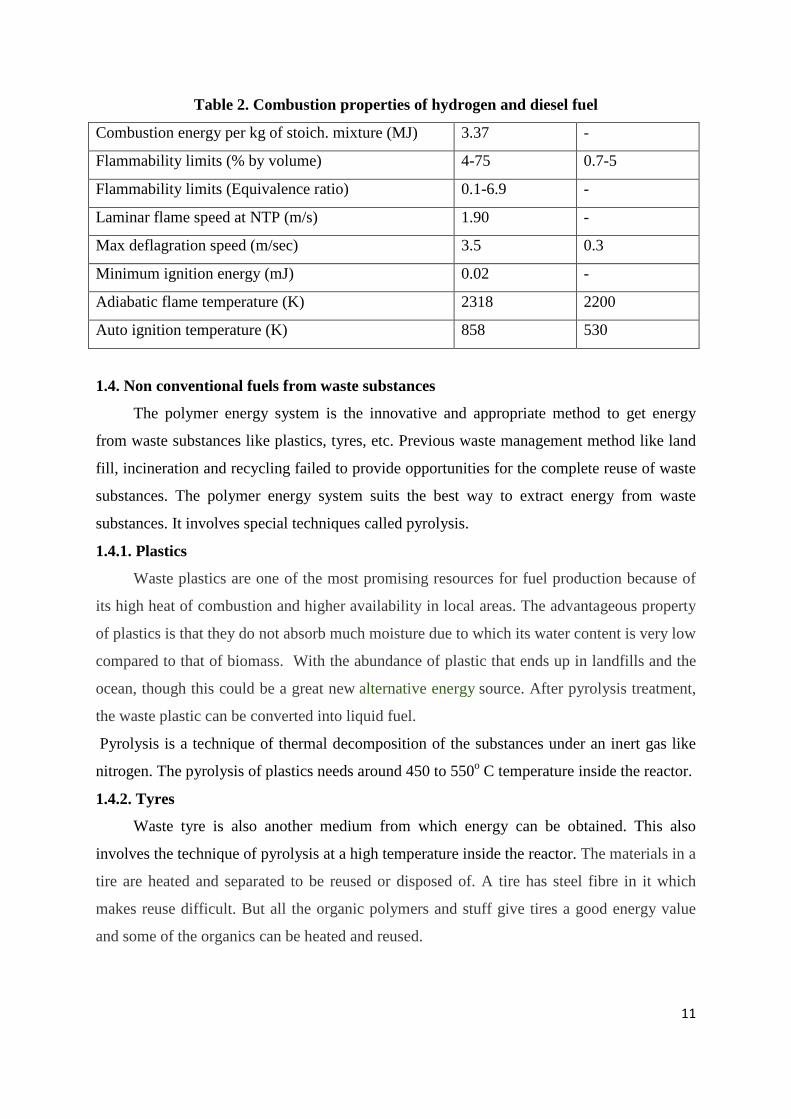
Table 2. Combustion properties of hydrogen and diesel fuel 11
Table 3. Properties of UTO40 and UTO100 13
Table 4. Test engine specification 22
Table 5. List of instruments and the range, accuracy and percentage uncertainties 25
Table 6. Energy share between hydrogen and UTO40 26
Table 7. Energy share between hydrogen and UTO100 26

viii
Nomenclature
Sl. no. Short form Full name
1. TO Transformer oil
2. UTO/UTO100 Used transformer oil as a sole fuel
3. UTO40 40% used transformer oil blended with 60% diesel fuel
4. DF Diesel fuel
5. BP Brake power
6. BTE Brake thermal efficiency
7. BSEC Brake specific energy consumption
8. EGT Exhaust gas temperature
9. CO Carbon monoxide
10. HC Hydrocarbon
11. CO2 Carbon dioxide
12. NOx Oxides of nitrogen
13. NO Nitric oxide
14. TDC Top dead centre
15. Y Total percentage uncertainty

CHAPTER 1
INTRODUCTION
1
CHAPTER -1
INTRODUCTION
1.1. General
The present energy situation has stimulated active research interest in non-petroleum,
renewable and non polluting fuels. Much of the present world’s energy demand may still be
supplied by exhaustible fossil fuels (natural gas, oil and coal), which are also the material
basis for the chemical industry. It is well known that combustion of fossil fuel causes air
pollution in cities and acid rains that damages forests, and also leads to produce more carbon
dioxide resulting environmental degradation. In recent year, the concern for cleaner air, due
to strict air pollution regulation and the desire to reduce the dependency on fossil fuels. Many
attempts are made to find various new and renewable energy sources to replace the existing
petroleum fuels. Alternative fuels are available in the form of solid, liquid, and gas. Biomass,
biodiesel from different vegetable oils and LPG are some of the examples for solid, liquid
and gaseous alternative fuels respectively which are commonly used to run the internal
combustion engines. Although these fuels are used, they generate considerable pollutants
from the internal combustion engines. Hydrogen is found to be cleaner fuel among all other
alternative fuels. Hydrogen is largely available and renewable in nature.
1.2. Alternative fuels
In view of the problem of fast dwindling reserves of irreplaceable petroleum fuels and
the hazards of environmental pollution caused by their combustion, attempts must be made to
develop the technology of alternate clean burning synthetic fuels. These fuels should be such
that they have attributes of perennial renewal, they perform well in the engine, and their
potential for environmental pollution should be quite low. Some alternative fuels in the form
of solid, liquid and gaseous fuels have been studied.
1.2.1. Solid Fuels
The best example of solid alternative fuel is energy from biomass. Biomass in its
traditional solid mass (wood and agriculture residue) and biomass in its non traditional form
(converted into liquid fuel). The first category is to burn the biomass directly and get the
energy. The second category, the biomass is converted into ethanol and methanol to be used
2
as liquid fuels in engines. The third category is to ferment the solid biomass anaerobically to
obtain a gaseous fuel called bio gas. Three solid bio fuels- wood, straw and refuse are being
burnt on an increasing scale in many countries to provide useful energy. Wood in the form of
cut logs, chips, and saw dust is currently used as a solid bio fuels. Now a day’s straw burning
furnace s are common in many countries. Municipal refuse is far from an ideal fuel. It is
messy to handle and has a low and variable energy content on average only about one third of
that of coal.
1.2.2. Liquid fuels
Alcohols and derivatives of vegetable oils are the best examples of this category,
replacing petrol and diesel as transport fuels in many countries and this process is likely to
accelerate as oil prices rises.
Alcohols:
Alcohols are of two types, ethanol and methanol which can be produced from
sugarcane waste, and many other agricultural products (renewable sources). Alcohol is
derived not directly from sugarcane but molasses – sugarcane by- products. All starch rich
plants like maize, tapioca, and potato can be used to produce alcohol as well as cellulosic
waste materials can also be used [1]
The advantages of using alcohol fuel are that it produces less overall emissions
compared to diesel and gasoline. Pure alcohol and their blending with various proportions
with diesel are utilized on diesel engine by many researchers. Methanol by itself is not a good
CI fuel because of its high octane number, but if small amount of diesel oil is used for
ignition, it can be used with good results. Ethanol has been used as alternative fuel for many
years in various countries. Brazil is probably the leading user. Minor engine modifications
are necessary for blends containing more than about 20% alcohol, or for almost pure alcohol:
these include on increased compression ratio, and altered timing etc. [2]
Vegetable oils:
Vegetable oils can also be used as a alternate liquid fuel for diesel engine. From
crushed seeds and nuts (for example, sun flower and rape seed, peanuts, palm, soya, and
corn) can be burnt in unmodified diesel engine. They can be blended with diesel fuel or used
directly.
3
1.2.3. Gaseous fuels
Alcohols, both ethanol and methanol, have been moderately successful as mixtures of
alcohols and diesel fuel. But ethanol resource materials are inadequate to have an impact on
the probable future requirements. Methanol, owing it its potential availability as a product of
coal conversion, continues to commend considerable interest, but both alcohols release CO2
gas on combustion, which tends to cause Green House Effect.
Gaseous fuels in comparison to the both solid and liquid alternate fuels have potential
to solve both the problems of energy crisis and air pollution. Among all other gaseous fuels
like Natural gas, LPG, CNG, Biogas, Fuel gas, hydrogen is best suited for compression
ignition engines. Hydrogen is almost in exhaustible natural source present in water. Also
hydrogen on combustion produces only water and NOx whose toxic effects are very less
compared to other fuels.
1.3. Hydrogen-Future fuel for IC engines
If we look at the past 2000 years history of fuels, usage has consistently moved in the
direction of a cleaner fuel: wood → coal→ petroleum→ propane →methane. The fuel
molecule has become smaller, leaner in carbon and richer in hydrogen. The last major move
was methane, which is a much cleaner burn than gasoline and diesel. So it is expected,
hydrogen to be a future fuel for the internal combustion engines [3]. Hydrogen has the
potential to solve both the environmental hazard faced by humankind i.e. air pollution and
global warming. Utilization of hydrogen for engine application is not a new concept. But
previously , there was no other motive in the minds of the investigators as it appeared that
petroleum , a perennial fuel source , would be available for all times to come. The problem of
availability of petroleum products was first time realised just after the Second World War. So
after that, hydrogen received special attention as an alternative engine fuel. A huge work is
done since 1960 on hydrogen engines. There is no fuel other than hydrogen that could meet
the twin challenges of the energy crisis and environmental pollution. Hydrogen is only one
such fuel. It can be produced from the renewable energy sources and as far the effects of
pollution is concerned, the common pollutants coming out of the exhaust of a gasoline or
diesel operated engine fuel are practically absent. Hydrogen as an engine fuel is exceptionally
clean burning. But use of hydrogen as an energy source in compression ignition engines
involves four basic issues [2]:

4
1. Production
2. Storage and Transportation
3. Safety Aspects
4. Utilization
1.3.1. Hydrogen Production
The hydrogen molecule is the smallest and lightest of all the molecules with unique
properties and uses. Hydrogen can be produced from water by using a variety of primary
energy sources including hydrocarbons, coal, nuclear, wind, biomass, and solar. Since
renewable energy sources (solar, wind, and /or biomass) are available in all parts of the
world, all countries will have access to hydrogen fuel. Wind, solar, and nuclear electrolyses
can produce pure hydrogen ready for use in fuel cells or in internal combustion engines. Also
the use of solar, wind does not add to environmental pollution. However, hydrogen derived
from the other energy sources will require separation and purification. Currently the
dominant technology for direct production of hydrogen is steam reforming from hydrocarbon
s. Hydrogen is also produced as a by-product of some chemical processes.
The other methods are electrolysis and thermolysis. The discovery and development of
less expensive methods of production of bulk hydrogen is relevant to the establishment of
a hydrogen economy. Some common methods for the production of hydrogen are discussed
in the following subsections:
1.3.1.1. Hydrogen Waste Stream
Hydrogen is used for the production of ammonia for fertilizer via the Haber process,
converting heavy petroleum sources to lighter fractions via hydro cracking and petroleum
fractions (dehydrocyclization and the aromatization process). It was common to vent the
surplus of hydrogen, nowadays the plants are balanced with hydrogen pinch which creates the
possibility of collecting the hydrogen for further use.
Hydrogen is also produced as a by-product of industrial chlorine production by
electrolysis. It can be cooled, compressed and purified for use in other processes on site or
sold to a customer via pipeline, cylinders or trucks.
5
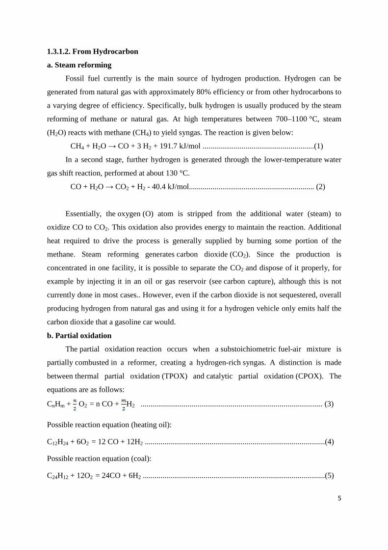
1.3.1.2. From Hydrocarbon
a. Steam reforming
Fossil fuel currently is the main source of hydrogen production. Hydrogen can be
generated from natural gas with approximately 80% efficiency or from other hydrocarbons to
a varying degree of efficiency. Specifically, bulk hydrogen is usually produced by the steam
reforming of methane or natural gas. At high temperatures between 700–1100 °C, steam
(H2O) reacts with methane (CH4) to yield syngas. The reaction is given below:
CH4 + H2O → CO + 3 H2 + 191.7 kJ/mol .........................................................(1)
In a second stage, further hydrogen is generated through the lower-temperature water
gas shift reaction, performed at about 130 °C.
CO + H2O → CO2 + H2 - 40.4 kJ/mol................................................................ (2)
Essentially, the oxygen (O) atom is stripped from the additional water (steam) to
oxidize CO to CO2. This oxidation also provides energy to maintain the reaction. Additional
heat required to drive the process is generally supplied by burning some portion of the
methane. Steam reforming generates carbon dioxide (CO2). Since the production is
concentrated in one facility, it is possible to separate the CO2 and dispose of it properly, for
example by injecting it in an oil or gas reservoir (see carbon capture), although this is not
currently done in most cases.. However, even if the carbon dioxide is not sequestered, overall
producing hydrogen from natural gas and using it for a hydrogen vehicle only emits half the
carbon dioxide that a gasoline car would.
b. Partial oxidation
The partial oxidation reaction occurs when a substoichiometric fuel-air mixture is
partially combusted in a reformer, creating a hydrogen-rich syngas. A distinction is made
between thermal partial oxidation (TPOX) and catalytic partial oxidation (CPOX). The
equations are as follows:
CnHm + O2 = n CO + H2 ............................................................................................. (3)
Possible reaction equation (heating oil):
C12H24 + 6O2 = 12 CO + 12H2 ............................................................................................(4)
Possible reaction equation (coal):
C24H12 + 12O2 = 24CO + 6H2 .............................................................................................(5)
6
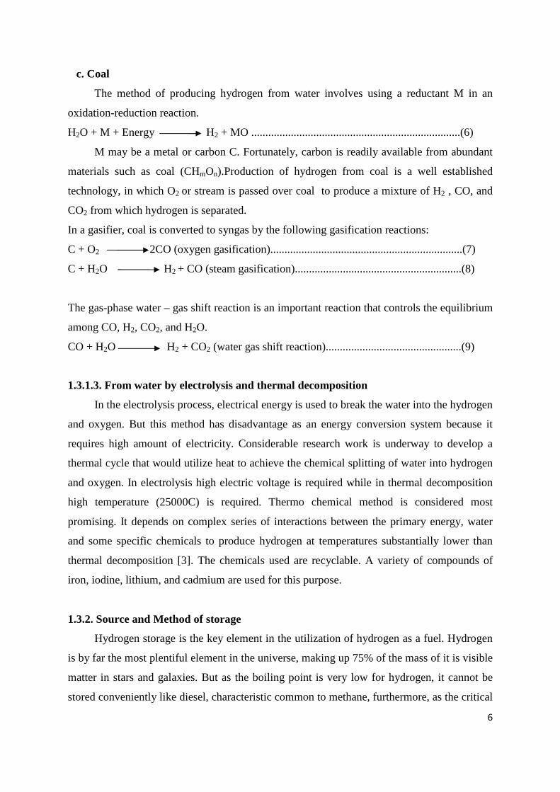
c. Coal
The method of producing hydrogen from water involves using a reductant M in an
oxidation-reduction reaction.
H2O + M + Energy H2 + MO ..........................................................................(6)
M may be a metal or carbon C. Fortunately, carbon is readily available from abundant
materials such as coal (CHmOn).Production of hydrogen from coal is a well established
technology, in which O2 or stream is passed over coal to produce a mixture of H2 , CO, and
CO2 from which hydrogen is separated.
In a gasifier, coal is converted to syngas by the following gasification reactions:
C + O2 2CO (oxygen gasification)....................................................................(7)
C + H2O H2 + CO (steam gasification)...........................................................(8)
The gas-phase water – gas shift reaction is an important reaction that controls the equilibrium
among CO, H2, CO2, and H2O.
CO + H2O H2 + CO2 (water gas shift reaction)................................................(9)
1.3.1.3. From water by electrolysis and thermal decomposition
In the electrolysis process, electrical energy is used to break the water into the hydrogen
and oxygen. But this method has disadvantage as an energy conversion system because it
requires high amount of electricity. Considerable research work is underway to develop a
thermal cycle that would utilize heat to achieve the chemical splitting of water into hydrogen
and oxygen. In electrolysis high electric voltage is required while in thermal decomposition
high temperature (25000C) is required. Thermo chemical method is considered most
promising. It depends on complex series of interactions between the primary energy, water
and some specific chemicals to produce hydrogen at temperatures substantially lower than
thermal decomposition [3]. The chemicals used are recyclable. A variety of compounds of
iron, iodine, lithium, and cadmium are used for this purpose.
1.3.2. Source and Method of storage
Hydrogen storage is the key element in the utilization of hydrogen as a fuel. Hydrogen
is by far the most plentiful element in the universe, making up 75% of the mass of it is visible
matter in stars and galaxies. But as the boiling point is very low for hydrogen, it cannot be
stored conveniently like diesel, characteristic common to methane, furthermore, as the critical

7
temperature is also very low, hydrogen cannot be liquefied easily like propane or butane.
Very low temperature refrigeration is required to liquefy hydrogen and maintain it in the
liquid phase. An alternative method of storage is in the gaseous phase in high pressure
cylinders. The compression of the gas to such high pressure requires the expenditure of much
expensive compression work and the provision of necessary infrastructure. Also, these
hydrogen gas cylinders would add significantly to the total weight, cost and bulkiness of the
fuel installation.
Hydrogen can also be stored in the form of various metal hydrides that would permit
the controlled release of hydrogen through the supply of heat, often from the engine exhaust
gas or its cooling water. These methods are of limited usefulness as they add much cost and
weight while reducing the flexibility of the fuel system and contributing to an increase in
undesirable emissions.
1.3.3. Safety aspects of hydrogen
The safety aspects of any fuel are closely related to the fuel application and the
postulated accident criteria. Hydrogen fuel cannot be handled exactly in the same manner as
the conventional petroleum based fuel, primarily because of the wide difference in
combustion characteristics of both fuels. In the event of a fuel spill, a fire hazard can develop
most rapidly with hydrogen. This is because hydrogen has higher diffusion velocity, high
buoyant velocity, wider flammability limits and lower ignition energy. The first two factors
determine the rate of mixing of fuel with air. The third factor determines the range of
equivalence ratio over which a flame can be sustained. The fourth factor determines the ease
with which a flammable mixture can be ignited
The wider flammable limits coupled with its higher burning velocity makes hydrogen
to possess greater potential for explosion compared to diesel. As the quenching distance is
inversely proportional to the laminar burning velocity, hydrogen air mixtures have lower
quenching distance increases the tendency of flashback. Also a flammable mixture of higher
burning velocity has a greater tendency to cause transition from flame to detonation during
flashback in long pipes.
Hydrogen is soluble in many materials including low alloy steels and stainless steels.
The solubility of hydrogen increases with temperature. However, even if the gas is at room
temperature, hydrogen embrittlement can still occur since it depends on pressure. The
selection of the chemical for hydrogen use is a very important safety consideration because
8
hydrogen reacts with a number of chemicals. For example, it explodes with chlorine in light.
Flame arrester should be incorporated in hydrogen fuelled engine so as to avoid backfire.
Tendency for knocking and pre-ignition could exist in some operating conditions. But
this is not a serious problem if severe effective operating controls can be exercised. Basically
hydrogen – air mixtures have high anti-knock characteristics due to high flame propagation
rates. High energy release rate increases thermal efficiency in I.C engines but could lead to
very rapid pressure rise and intolerable engine roughness.
Some important measures must be taken to prevent explosion from hydrogen cylinders
like installation of explosion-suppression systems, flame traps, flame suppressors, explosion
relief devices and rapid closing devices [2]. There are no safety problems in the industrial
and commercial applications of hydrogen as indicated by the past experience in industry and
commerce. However there may be safety problem in transportation and domestic uses, which
require careful study before replacing present fuels by hydrogen.
1.3.4. Utilization of hydrogen in compression ignition engines
As far as the utilization of hydrogen in compression ignition engine system is
concerned, the techniques of hydrogen induction play a very important role [8]. There are
basically five different techniques of hydrogen induction that were carried out in the last few
decades by the researchers. They are
1. Carburetion technique
2. Continuous manifold injection (CMI)
3. Timed manifold injection (TMI)
4. Low pressure direct cylinder injection (LPDI)
5. High pressure direct cylinder injection (HPDI)
The above five points are the techniques to optimize the basic procedure of induction of
hydrogen on diesel engines. In general, hydrogen can be used in diesel engines by two ways
[4]:
1. By introducing hydrogen with air and using a spray of diesel oil to ignite the mixture
that is by the dual fuel mode.
2. By introducing hydrogen directly into the cylinder at the end of compression. It is also
possible to feed a very lean hydrogen air mixture during the intake into an engine and
then inject the bulk of the hydrogen towards the end of the compression stroke.
9
Hydrogen, due to its wider ignition limits, the requirement of throttling is less
compared to operation on diesel. This restricts the pumping loss and increases the thermal
efficiency. The hydrogen can be used as a sole fuel in petrol engine but cannot be used
directly in a diesel engine. The reason is due to high auto ignition temperature (858K) which
cannot be achieved by compression alone. Therefore some other fuel of low self ignition
energy (it may be diesel or other fuels) is required which acts as an ignition source for
hydrogen. The combustion of the hydrogen occurs by only achieving its auto ignition
temperature by flame initiation [27]. Therefore the hydrogen is always used in a dual fuel
mode in compression ignition engine. Less cyclic variations are encountered with hydrogen
than with other fuels. This lead to a reduction in emissions, improved efficiency, and quieter
and smoother operation. Due to its high burning velocity, it can also be used to improve the
combustion rate of fuels having slow burning characteristics [31]. Apart from the above five
techniques, hydrogen can also be inducted continuously at a less flow rate, at some distance
from the intake manifold.
1.3.5. Physical properties of hydrogen
Hydrogen shows the lowest boiling point and melting point next to helium. The boiling
point of hydrogen is 20.27K while that of helium is 20K. Fuels that are gases at atmospheric
conditions (such as hydrogen and natural gas) are less convenient as they must be stored as a
pressurised gas or as a cryogenic liquid.
Pure hydrogen is odourless, colourless and tasteless. A stream of hydrogen from a leak
is almost invisible in day light. Compounds such as mercaptans and thiophanes that are used
to scent natural gas may not be added to hydrogen for fuel cell use as they contain sulphur
that would poison the fuel cells.
Hydrogen is non-toxic but can act as a simple asphyxiant by displacing the oxygen in
the air.
In an enclosed area, small leaks pose little danger of asphyxiant whereas large leaks can
be serious problem since the hydrogen diffuses quickly to fill the volume. The potential for
asphyxiant in unconfined areas is almost negligible due to the high buoyancy and diffusivity
of hydrogen.
Hydrogen is detonable over a wide range of concentrations when confined. However, it
is difficult to detonate if un confined, similar to other conventional fuels.

10
The hydrogen-air flame is hotter than methane air flame and cooler than gasoline at
stoichiometric conditions (22070C compared to 19170C for methane and 23070C for gasoline
and that of diesel 23270C).
The lower calorific value of hydrogen on mass basis is about 2.5 times that of most
hydrocarbon fuels. Yet the flame temperature for hydrogen-air mixtures is not much higher
than that for hydrocarbon fuels-air mixtures.
The property of wider flammability limits for hydrogen air mixtures are advantageous
in diesel engines, to control the energy rates. The effects of hydrogen on flame stability are
opposite to those of methane and diesel. While the tendency of flashback is more, the
tendency for the blow off is less because of its high burning velocity and small penetration
distance.
Hydrogen possess high rate of diffusion into air than diesel fuel. This promotes rapid
mixing and enables to avoid premixing of fuel with air.
Hydrogen operated engines have tendency to knock. But this is not a serious problem if
severe effective operating controls can be exercised. Various chemical properties of hydrogen
and their comparison with diesel fuel are given in Table 1. While some combustion properties
of hydrogen are given in Table 2.
Table 1. Some relevant properties of hydrogen
Property Hydrogen Diesel
Formula H2 C8-C20
Density at 1 atm and 300 K(kg/m3) 0.082 833-881
Stoichiometric air fuel ratio (kg/kg) 34.3 14.5
Higher Heating Value (MJ/kg) 141.7 45.9
Lower Heating Value (MJ/kg) 119.7 43.0
Kinematic viscosity at 300 K(mm2/s) 110 3.292
Thermal conductivity at 300 K (W/mK) 182.0 0.1768
Diffusion coefficient into air at NTP (cm2/s) 0.61 -
Specific gravity 0.091 0.83
Boiling point(K) 20.27 436-672
Cetane number - 40-55
Molecular weight(g/mole) 2.015 170
11
Table 2. Combustion properties of hydrogen and diesel fuel
Combustion energy per kg of stoich. mixture (MJ) 3.37 -
Flammability limits (% by volume) 4-75 0.7-5
Flammability limits (Equivalence ratio) 0.1-6.9 -
Laminar flame speed at NTP (m/s) 1.90 -
Max deflagration speed (m/sec) 3.5 0.3
Minimum ignition energy (mJ) 0.02 -
Adiabatic flame temperature (K) 2318 2200
Auto ignition temperature (K) 858 530
1.4. Non conventional fuels from waste substances
The polymer energy system is the innovative and appropriate method to get energy
from waste substances like plastics, tyres, etc. Previous waste management method like land
fill, incineration and recycling failed to provide opportunities for the complete reuse of waste
substances. The polymer energy system suits the best way to extract energy from waste
substances. It involves special techniques called pyrolysis.
1.4.1. Plastics
Waste plastics are one of the most promising resources for fuel production because of
its high heat of combustion and higher availability in local areas. The advantageous property
of plastics is that they do not absorb much moisture due to which its water content is very low
compared to that of biomass. With the abundance of plastic that ends up in landfills and the
ocean, though this could be a great new alternative energy source. After pyrolysis treatment,
the waste plastic can be converted into liquid fuel.
Pyrolysis is a technique of thermal decomposition of the substances under an inert gas like
nitrogen. The pyrolysis of plastics needs around 450 to 550o C temperature inside the reactor.
1.4.2. Tyres
Waste tyre is also another medium from which energy can be obtained. This also
involves the technique of pyrolysis at a high temperature inside the reactor. The materials in a
tire are heated and separated to be reused or disposed of. A tire has steel fibre in it which
makes reuse difficult. But all the organic polymers and stuff give tires a good energy value
and some of the organics can be heated and reused.
12
1.4.3. Waste/Used Transformer Oil
The oil that is used in the transformers for the cooling purpose is thrown out in the form
of waste after use. The waste transformer oil possesses lots of dirt. After cleaning, it can also
be used as a alternate fuel for the internal combustion engines. The advantage of this waste
transformer oil is that it does not need the technique of pyrolysis.
1.5. Transformer oil
Transformer oils are an important class of insulating oils. It acts as heat transfer
medium so that the operating temperature of a transformer does not exceed the specific
acceptable limits. Transformer oils are produced from wax-free naphthenic oils. Although
these types of crudes permit production of exceptionally low pour point insulating oils
without the need for dew axing or special attention to the degree of fractionation or distillate
cut width, they also contain high percentages of sulphur and nitrogen which must be removed
in order to satisfy the stringent stability requirements of insulating oils [5]. It has been found
that a highly aromatic, low paraffinic content naphthenic crude oil is a suitable raw material
to prepare good transformer oil.
Mineral oil is the base material for transformer oil that is used as coolant in
transformers in electrical substations and welding transformers. After prolonged use, the
transformer oil becomes deteoriated and becomes waste. However, the waste or used
transformer oil (UTO) posses a considerable heating value and some of the properties similar
to that of diesel fuel [7]. Therefore, it can be used as an alternative fuel in compression
ignition engines. But the use of UTO in compression ignition engine gives high vibration.
Therefore attempts have been made to utilize the heating value of hydrogen to reduce the
viscosity of UTO by inducting hydrogen into the suction.
1.5.1. Transformer oil identification [6]
Product Name: Transformer Oil,
Chemical Name: Severely Hydro treated Heavy Naphthenic Distillate
Chemical Family: Petroleum Hydrocarbon Oil
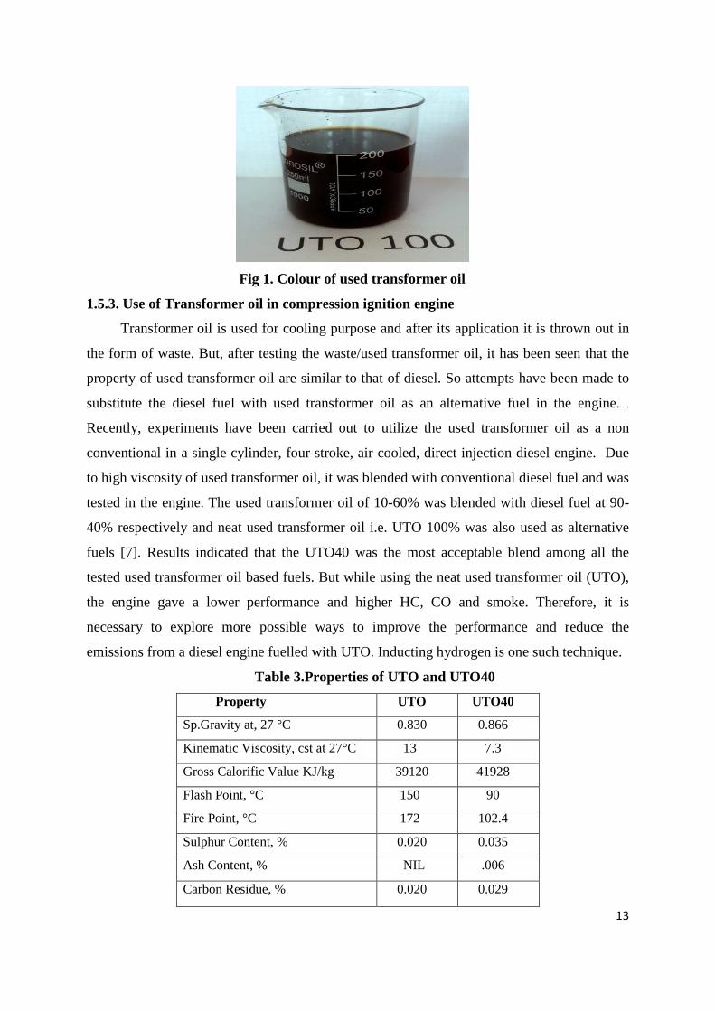
1.5.2. Colour of Used Transformer oil
The used transformer oil appears to be dark brown in colour and the colour of sole used
transformer oil is given in Fig 1.. The properties of UTO and UTO40 are given in Table 3.
13
Fig 1. Colour of used transformer oil
1.5.3. Use of Transformer oil in compression ignition engine
Transformer oil is used for cooling purpose and after its application it is thrown out in
the form of waste. But, after testing the waste/used transformer oil, it has been seen that the
property of used transformer oil are similar to that of diesel. So attempts have been made to
substitute the diesel fuel with used transformer oil as an alternative fuel in the engine. .
Recently, experiments have been carried out to utilize the used transformer oil as a non
conventional in a single cylinder, four stroke, air cooled, direct injection diesel engine. Due
to high viscosity of used transformer oil, it was blended with conventional diesel fuel and was
tested in the engine. The used transformer oil of 10-60% was blended with diesel fuel at 90-
40% respectively and neat used transformer oil i.e. UTO 100% was also used as alternative
fuels [7]. Results indicated that the UTO40 was the most acceptable blend among all the
tested used transformer oil based fuels. But while using the neat used transformer oil (UTO),
the engine gave a lower performance and higher HC, CO and smoke. Therefore, it is
necessary to explore more possible ways to improve the performance and reduce the
emissions from a diesel engine fuelled with UTO. Inducting hydrogen is one such technique.
Table 3.Properties of UTO and UTO40
Property UTO UTO40
Sp.Gravity at, 27 °C 0.830 0.866
Kinematic Viscosity, cst at 27°C 13 7.3
Gross Calorific Value KJ/kg 39120 41928
Flash Point, °C 150 90
Fire Point, °C 172 102.4
Sulphur Content, % 0.020 0.035
Ash Content, % NIL .006
Carbon Residue, % 0.020 0.029

CHAPTER 2
LITERATURE SURVEY
14
CHAPTER 2
LITERATURE SURVEY
L.M.Das [8] studied that the mixture formation method plays a important role for the
practical application of a hydrogen fuelled specific engine. The use of cryogenic hydrogen
supplied from the liquid hydrogen tank, method of late fuel injection are studied and
evaluated. It was suggested that the integrated fuel induction and storage method must be
designed for an hydrogen specific engine
N.Saravanan et al. [9] did experiments on DI diesel engine supplemented with
hydrogen fuel. Two techniques were adopted to inject hydrogen inside the engine cylinder ;(
1) Carburetion technique and (2) TPI –Timed Manifold Injection technique and compared
their performance, emission and combustion parameter with sole diesel by adopting both the
techniques. It was concluded that TPI technique gives better performance compared to
carburetion technique. The knock can occur at high flow rate of hydrogen. They concluded
the optimum hydrogen enrichment with diesel was 30% by volume.
N. Saravanan et al. [10] inducted hydrogen in a DI diesel engine adopted EGR
technique to reduce NOx emission. The arrangement was provided in such a way that, some
part of exhaust gases is sent back to the engine intake manifold. This arrangement is called as
Exhaust Gas Recirculation (EGR). Minimum Concentration of NOx is 464 ppm with 25 %
EGR.
N.Saravanan and G. Nagarajan [11] conducted experiment were on a DI Diesel
engine with hydrogen in the dual fuel mode The optimized injection timing was found to be
5CA before gas exchange top dead centre (BGTDC) with injection duration of 30 CA for
hydrogen diesel dual fuel operation in hydrogen port injection. The optimum hydrogen flow
rate is found to be 7.5 lpm based on the performance, combustion and emissions behaviour of
the engine. The brake thermal efficiency for hydrogen diesel dual fuel operation increases by
17% compared to diesel at optimized timings. The NOX emission is found to be similar at
75% load and full load for both hydrogen and diesel operation. However the concentration is
lower at lower loads in hydrogen dual fuel operation due to lean mixture operation. The
15
smoke emission reduces by 44% in hydrogen diesel dual operation compared to diesel
operation. The CO and HC for hydrogen operation at optimized conditions are same as that of
diesel emissions. It was concluded that the engine operated smoothly with hydrogen except
at full load that resulted in knocking especially at high hydrogen flow rates.
N. Saravanan et al. [12] investigated the combustion analysis on a direct injection DI
diesel engine using hydrogen with diesel and hydrogen with diethyl ether as ignition source.
Hydrogen was inducted hydrogen through intake port and diethyl ether through intake
manifold and diesel was injected directly inside the combustion chamber. The optimized
timing for the injection of hydrogen was 50 CA before gas exchange top dead centre and
400CA after gas exchange top dead centre for diethyl ether. They concluded that the
hydrogen with diesel results in increased brake thermal efficiency by 20% and oxides of
nitrogen showed an increase of 13% compared to diesel whereas hydrogen – diethyl ether
showed a higher brake thermal efficiency of 30% with a significant reduction in oxides of
nitrogen compared to diesel.
Li Jing Ding et al. [13] did experiment by using hydrogen as a sole fuel and then
hydrogen mixed with petrol and hydrogen diesel oil mixed fuel. The main aim was to
improve the combustion properties of hydrogen fuelled engine. It was concluded that increase
in compression ratio is the best technique to make petrol engine or diesel engine free from
back fire. An increase in compression ratio brings about a wider back fire free range of
engine output and an increase in thermal efficiency and a reduction in exhaust gas
temperature. Smoke can be reduced by using diesel oil – hydrogen mixed fuels (rather than
oil alone).Under low speed and in high load conditions the result will be better.
J.M.Gomes Antunes et al. [14] described the development of an experimental set up
for the testing of a diesel engine in the direct injection hydrogen fuelled mode. The use of
hydrogen direct injection in a diesel engine gave a higher power output to weight ratio
when compared to conventional diesel fuelled operation with approximate 14% high peak
power. The direct injection of hydrogen allows much better control of engine operation
compared to port injection in HCCI mode. Comparison of direct injection of hydrogen with
HCCI mode of operation was done and concluded that the direct injection of hydrogen
offers the possibility to control and limit excessive mechanical loads while this is virtually

16
uncontrolled in the HCCI mode of operation. They also observed the reduction of NOx
emission level.
L.M. Das [15] studied the phenomenon such as backfire, pre ignition, knocking and
rapid rate of pressure rise and presented in his review paper on the development of hydrogen
fuelled internal combustion engines. According to him,” Hydrogen is the only one such fuel
which can meets the twin challenges of the energy crisis and the environmental pollution”.
L.M. Das [16] suggested some safety measures to be adopted to avoid undesirable
combustion phenomena. The use special effective hydrogen sensors are advantageous to
monitor this combustible gas in the hydrogen environment. The need for reliable ventilation
of the hydrogen system surroundings is very important but in some operating condition it is
not possible to permit sufficient ventilation to some test chambers. In such cases the potential
hazards inside the chambers can be rendered non hazardous by building an atmosphere of
inert gases. Nitrogen, Carbon dioxide etc can be used for this purpose. The flame arrester
should be there so as to suppress the back fire. Flame trapper have been observed to work
extremely satisfactorily in overcoming the undesirable combustion problems especially back
fire. Installation of a non return valve in the fuel line is also very important which prevents a
reverse flow to the system. The selection of the chemical for hydrogen is a very important
safety considerations and to prevent hydrogen embrittlement because hydrogen reacts with a
number of chemicals. For example, it explodes chlorine in light.
L.M. Das [17] studied the nature and formation mechanism of different types of
pollutants emitted from a hydrogen operated diesel engine system. It was concluded that neat
hydrogen operated engines produce close to zero ozone, particulates, sulphur dioxide,
benzenes which are usually present in a conventional engines exhaust. It was also concluded
that the equivalence ratio play a very important role for NOx controlling parameter and the
optimum should be 0.6. Hydrocarbons and carbon monoxide emissions which are extremely
small could be eliminated by regular maintenance and inspection programmes and by
excessive burning of oil.
H.B. Mathur et al. [18] did experimental investigation on a hydrogen fuelled diesel
engine to measure the performance characteristics through charge diluents. The results shows

17
that the thermal efficiency of the engine of the hydrogen fuelled engine is better as compared
to neat diesel at 10 LPM, 20LPM, 30 LPM of hydrogen flow rates. The thermal efficiency of
engine at hydrogen flow rate of 20 LPM gives better thermal efficiency compared to 30 LPM
of hydrogen flow rate. It is found that the engine started knocking when the hydrogen flow
rate is exceeding after 40 LPM. After that helium, nitrogen and water was inducted as
diluents respectively and checked the performance of engine. Nitrogen as diluents also helps
control engine knocking and also improves the optimum full-load hydrogen energy
substitution. In addition, it gives the best thermal efficiency and power output when its
percentage is maintained at 30% by volume of hydrogen substituted. Among the various
proportions of water which could be inducted for charge dilution, 2460 ppm water
concentration has been found to be the optimum level which enables the highest full-load
hydrogen energy substitution – around 66% without undue engine knock and with only a very
nominal loss of engine power and efficiency.
H.B. Mathur et al. [19] reported the test results of the study relating to the effect of
diluents like helium, nitrogen and water in various proportions on smoke and oxides of
nitrogen emission on diesel engine. It was found that helium showed a positive effect on
controlling these pollutants while nitrogen only reduced smoke emission levels. Water is
considered as the best diluents because it has the best effect on the emission characteristics of
the engine when compared with the other two diluents. The greater the amount of water
induced, the better the control on the emission parameters. Smoke levels are almost
negligible, while NOx emission levels are reduced to baseline values. 10 % of helium by
volume of hydrogen is considered the best proportion for helium and 10 % of nitrogen by
volume of hydrogen is considered the best proportion for the nitrogen. Whereas the optimum
level of water has been found to be 2460 ppm. Diluents with this optimum proportion gives
better emission characteristics.
L.M. Das [20] studied the hydrogen combustion techniques in various thermal systems.
He also studied the hydrogen – oxygen reaction mechanism. It has been observed that under
ambient conditions of temperature, hydrogen and oxygen do not enter into any direct reaction
between them in absence of catalyst. But if the mixture is exposed to light oxygen gets
activated usually by dissociation. Also in the presence of sensitizers of Cl. N2O and NH3, a

18
set of secondary reactions takes place and form H atoms These H atoms enter into a reaction
with the activated oxygen thus forming H2O.
The burning of hydrogen gas was classified into two categories (1) Deflagration and (2)
Detonation. The abnormal combustion in hydrogen engines are classified into three types:
1. Abnormally high pressure rise
2. Occurrence of pre ignition in combustion chamber and sequential advancement of pre
ignition and backfire into intake manifold.
3. Occasional backfire in very lean hydrogen –air mixture or idling operation.
Varde and Varde [21] conducted work on hydrogen substitution on a diesel engine.
Results shows the 50% reduction of smoke at part load when the hydrogen energy share was
15%of the total fuel. NOx was seen to increase with hydrogen substitution at both part and
full load.
T. Lakshmanan and G.Nagarajan [22] did experiment on a single cylinder, air
cooled DI diesel engine by inducting acetylene gas at different flow rates in dual fuel mode.
The diesel acts as a ignition source. It was found that the brake thermal efficiency was lower
compared to baseline diesel operation but there is a reduction in HC, CO, CO2 and smoke
emission. However, a significant increase in NOx emission was observed.
M.Senthil Kumar et al. [23] conducted research on dual fuel mode by inducting
hydrogen on a compression ignition engine. Neat jatropha oil was taken as a main fuel and
hydrogen was inducted for the dual fuel operation. Results were compared with diesel when
used as main fuel, in addition with hydrogen. Results indicated increase in brake thermal
efficiency and lower smoke levels, when hydrogen is inducted but NO emission was found to
be high. The injection timing was optimized as 29o CA before TDC for jatropha-hydrogen
operation.
J. Nazar et al. [24] did experiment on stationary agricultural type diesel engine in a
dual fuel mode. For dual fuel mode, karanja oil and hydrogen gas was taken. It was seen that
by operating the engine with neat karanja oil , there was slight reduction in thermal efficiency
as well as emissions were also found to be high. But on operating the engine with dual fuel
mode by taking karanja oil and hydrogen gas, the thermal efficiency increased from 30% to

19
32% at full load with 15% of hydrogen energy share out of total energy share of fuel. Also
reduction in emissions was observed, except NO emission at full load.
G.Sankaranarayanan et al. [25] did experiment on madhuca indica oil enriched with
hydrogen air mixture. The brake thermal efficiency was increased of about 24% with 40%
hydrogen enrichment than of raw madhuca indica oil. At lean mixture of hydrogen NO
concentration was found to be low. The maximum NO emission was found to be 402 ppm at
full load when hydrogen energy share is 40%.
G.Nagarajan et al. [26] did experiment by taking ethanol as an fuel for conventional
diesel engines. Since the cetane number of ethanol is very low, it cannot be used as a sole fuel
in diesel engine. It was found that the temperature achieved after compression stroke was not
sufficient to ignite the ethanol. Therefore a di ethyl ether (DEE) was used just before the port
in the form of droplets that is drawn into the engine cylinder along with the intake of air. The
DEE has low self ignition energy and gets ignited which in turn ignites the ethanol. Thus
engine was modified to operate on dual fuel type. It was found that the brake thermal
efficiency of the engine was higher than diesel at about 36% at 75% load for ethanol-DEE,
while that of diesel was 30%.HC emission was found to be higher in ethanol –DEE than
diesel at about 434 ppm due to the increased amount of HCs present in the quench and
crevics zones. Soot formation and smoke was also low with ethanol-DEE combination.
T.Lakshmanan and G.Nagarajan [27] studied the possibility of utilizing the
acetylene gas fuel in a dual fuel mode. Diesel acted as a ignition source. Acetylene was
inducted at varied flow rates of 110 g/s, 180 g/s, and 240 g/s. Acetylene was introduced by
timed manifold injection technique. For that ECU –Electronic Control Unit was mounted.
The optimum condition in manifold injection was found to be 100 ATDC with injection
duration of 900 crank angles. Reduction in all type of emission was noticed except smoke.
There was slightly increase in smoke emission.
R.G.Papagiannakis et al. [28] did experiment on duel fuel mode on a single cylinder,
air cooled direct injection diesel engine having bowl in piston type combustion chamber.
Attempts have been made to utilize natural gas as a alternative fuel in diesel engine. The NO
and soot formation was found to be very low with natural gas supplement liquid diesel fuel
20
operation on diesel engine. But the brake thermal efficiency was evaluated to be lower
compared to neat diesel fuel.
Seung Hyun Yoon and Chang Sik Lee [29] carried out an experimental investigation
to study the influence of dual fuel combustion characteristics on the exhaust emissions and
combustion performance in a diesel engine fuelled with biogas- biodiesel dual fuel. The
engine used for this study was based on four cylinder, turbo charged, pre-chamber,
compression ignition engine with a single overhead cam. It was concluded that at 60%
engine load, on dual fuel mode showed slightly higher peak combustion pressure and
indicated mean effective pressure compared to ultra low sulphur diesel fuel, whereas the
ignition delay gets shortened. The exhaust gas temperature was found to low in case of dual
fuel mode. At low loads the total brake specific fuel consumptions for dual fuel combustion
for both fuels were considerably higher than for single fuel combustion.
M.Senthil Kumar et al. [30] carried out experiment on dual fuel mode. Engine was
modified to run using vegetable oils as primary and pilot fuels. Results indicated that the
orange oil can be used as inducted fuel for reducing smoke and NO emissions with improved
brake thermal efficiency in a diesel engine fuelled with vegetable oils and its esters for a dual
fuel mode of operation.
G.A. Rao et al. [31] modified the engine to operate on dual fuel mode to reduce the
usage of diesel and also to reduce pollution. The gaseous fuel LPG was used as a inducted
fuel and diesel was used as a main fuel. The results indicated increase in brake thermal
efficiency and lower smoke level.
From the above available literatures, it is understood that using used transformer oil as a main fuel and inducting hydrogen at a small and constant flow rate of 4 lpm is a new one and nobody has done research on these field (i.e. utilizing hydrogen and used transformer oil together in compression ignition engine).

CHAPTER 3
EXPERIMENTAL INVESTIGATION
21
CHAPTER 3
EXPERIMENTAL INVESTIGATION
3.1. EXPERIMENTAL PROCEDURE
. The engine used for the present investigation is a single cylinder four stroke air cooled
diesel engine. Initially the engine was operated with neat diesel and the performance,
emission and combustion parameters were evaluated. Then the engine was allowed to run
with UTO40 and UTO100/UTO respectively without hydrogen. Again the performance,
emission and combustion parameters were evaluated. Now for the third test, hydrogen gas is
introduced by considering first UTO40 as a main fuel and then UTO100 as a main fuel
respectively.
Hydrogen fuel from a high pressure cylinder was inducted through an intake pipe. A
double stage diffusion pressure regulator was employed over the high pressure cylinder. The
regulator is used to control the outlet pressure. Hydrogen fuel, at a pressure of 2 bars and a
constant flow rate of 4 lpm is then supplied to the flame arrester and flame trap and finally to
the intake pipe (a distance of 40 cms away from the intake manifold) where it mixes with air
and finally, this hydrogen- air mixture get inducted into the engine cylinder. Used
transformer oil of 40% blended with 60% diesel fuel (UTO40) on volume basis is introduced
from the fuel tank into the engine cylinder by direct injection. Then engine is allowed to run
for different loads. The same procedure is adopted by considering sole used transformer oil
(UTO/UTO100) as a main fuel with hydrogen flow rate of 4 lpm. The performance and
combustion parameter is obtained by computer provided into data acquisition system. AVL
exhaust gas analyser is used to calculate the emission parameter whereas smoke meter is used
to get smoke values. Combustion diagnosis was carried out by means of a Kistler make
quartz piezoelectric pressure transducer (Model Type 5395A) mounted on the cylinder head
in the standard position. The air flow rate is calculated according to the difference in the level
of water in the U- tube manometer mounted into the air suction line. The engine specification
is given in the Table 4. The test is also carried out by considering diesel as a main fuel
without using hydrogen. All the test results of engine using UTO40 and UTO as a main fuel
with hydrogen induction were compared with neat diesel fuel and other two main fuels
without hydrogen.

22
Table 4. Test engine specification
Make Kirloskar
Type of Engines 4-stroke cycle, single cylinder,
compression ignition engine
Speed, rpm 1500 rpm
Bore, mm 87.5
Stroke, mm 110
Compression ratio 17.5
Method of cooling
Injection timing, o CA
Nozzle opening pressure, bar
Air cooled with radial fan
23o before TDC
200 kg /cm2
3.2. ENGINE MODIFICATION FOR HYDROGEN OPERATION
3.2.1. Hydrogen admission
The engine was modified to operate on hydrogen. A valve was provided at a distance
of 40 cm from the intake manifold. Hydrogen was allowed to pass through this valve. A
high pressure hydrogen cylinder is used having inlet pressure of 0-280 kg/cm2
approximately 280 bars. The hydrogen gas purity is 99.999%.
3.2.2 Hydrogen Supply
The hydrogen gas is allowed to pass through the intake pipe at an outlet pressure of 2
bar pressure and al flow rate of 4 lpm. The pressure is regulated by a double stage diffusion
pressure regulator mounted on to the hydrogen cylinder. The specification of pressure
regulator is given below:
Inlet Pressure Max 0-280 kg/cm2
Outlet pressure Max 0-07 kg/cm2
Inlet Connection: 5/8” BSP (M) LH
Outlet Connection: ¼ inches OD Tube
Gas Service: Hydrogen
3.2.3. Flash back arrester
A flash back arrestor is a safety device that shuts off gas flow in event of flash back.
Flashback is the combustion of a flame mixture that can occur within your gas management
system. This can travel back through the line of the gas management system to the gas
23
source if flash back arrestor is not in line. A flash back arrestor shuts off gas flow and
extinguishes the flame before it can reach your gas source. Several factors can cause flash
back, including failing to purge line properly, using improper pressure, leaks in your gas
management system and improper system operation.
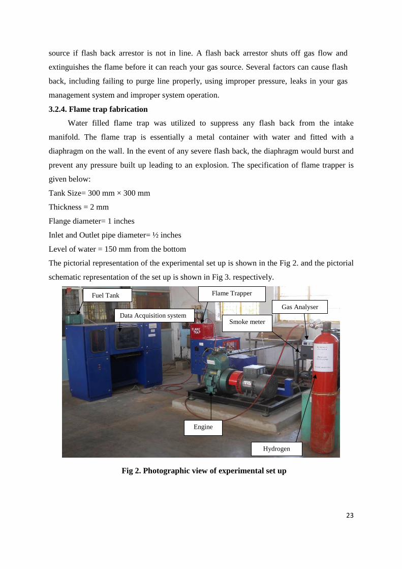
3.2.4. Flame trap fabrication
Water filled flame trap was utilized to suppress any flash back from the intake
manifold. The flame trap is essentially a metal container with water and fitted with a
diaphragm on the wall. In the event of any severe flash back, the diaphragm would burst and
prevent any pressure built up leading to an explosion. The specification of flame trapper is
given below:
Tank Size= 300 mm × 300 mm
Thickness = 2 mm
Flange diameter= 1 inches
Inlet and Outlet pipe diameter= ½ inches
Level of water = 150 mm from the bottom
The pictorial representation of the experimental set up is shown in the Fig 2. and the pictorial
schematic representation of the set up is shown in Fig 3. respectively.
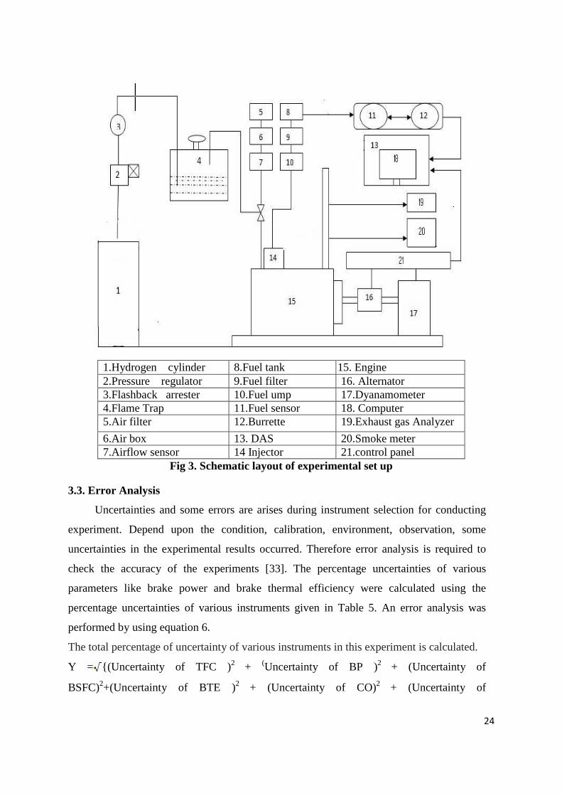
Fig 2. Photographic view of experimental set up
Fuel Tank
Data Acquisition system Gas Analyser
Hydrogen
Engine
Flame Trapper
Smoke meter
24
1.Hydrogen cylinder 8.Fuel tank 15. Engine 2.Pressure regulator 9.Fuel filter 16. Alternator 3.Flashback arrester 10.Fuel ump 17.Dyanamometer 4.Flame Trap 11.Fuel sensor 18. Computer 5.Air filter 12.Burrette 19.Exhaust gas Analyzer
6.Air box 13. DAS 20.Smoke meter 7.Airflow sensor 14 Injector 21.control panel
Fig 3. Schematic layout of experimental set up
3.3. Error Analysis
Uncertainties and some errors are arises during instrument selection for conducting
experiment. Depend upon the condition, calibration, environment, observation, some
uncertainties in the experimental results occurred. Therefore error analysis is required to
check the accuracy of the experiments [33]. The percentage uncertainties of various
parameters like brake power and brake thermal efficiency were calculated using the
percentage uncertainties of various instruments given in Table 5. An error analysis was
performed by using equation 6.
The total percentage of uncertainty of various instruments in this experiment is calculated.
Y = {(Uncertainty of TFC )2 + (Uncertainty of BP )2 + (Uncertainty of
BSFC)2+(Uncertainty of BTE )2 + (Uncertainty of CO)2 + (Uncertainty of

25
CO2)2+(Uncertainty of UBHC )2 + (Uncertainty of NOx )2 + (Uncertainty of Smoke )2 +
(Uncertainty of EGT )2 +(Uncertainty of pressure Pickup )2 ……………………………...(6)
Table 5. List of instruments range, accuracy and percentage uncertainties
Sl.
no.
Instruments Range
Accuracy
Percentage
uncertainties
1 Gas Analyzer NOx 0-5000ppm
HC
CO
CO2
±20 ppm
±15 ppm
±0.02 %
±0.03%
±0.2
±0.2
±0.2
±0.15
2 Smoke level
measuring
instrument
BSN 0-10
±0.2
±1.0
3 EGT sensor 0-1000 °C ±1°C ±0.15
4 Load indicator 0-100 kg ±10 rpm
±1.0
5 Burette for fuel
measurement
- ±0.2 cm3 ±0.15
6 Manometer - ±1 mm ±1.0
So by inserting the values of percentage uncertainties of various instrument in equation 6, the
total percentage of uncertainties was found to be:
Y = {(1.5)2 + (0.2)2+ (1.5)2 + (1)2 + (0.2)2 + (0.15)2 + (0.2)2+(0.2)2 + (1.0) 2+ (0.15)2 + (1.0)2 }
Y= ±2.77%.
26
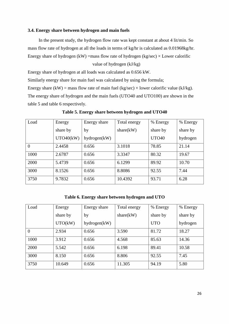
3.4. Energy share between hydrogen and main fuels
In the present study, the hydrogen flow rate was kept constant at about 4 lit/min. So
mass flow rate of hydrogen at all the loads in terms of kg/hr is calculated as 0.01968kg/hr.
Energy share of hydrogen (kW) =mass flow rate of hydrogen (kg/sec) × Lower calorific
value of hydrogen (kJ/kg)
Energy share of hydrogen at all loads was calculated as 0.656 kW.
Similarly energy share for main fuel was calculated by using the formula;
Energy share (kW) = mass flow rate of main fuel (kg/sec) × lower calorific value (kJ/kg).
The energy share of hydrogen and the main fuels (UTO40 and UTO100) are shown in the
table 5 and table 6 respectively.
Table 5. Energy share between hydrogen and UTO40
Load Energy
share by
UTO40(kW)
Energy share
by
hydrogen(kW)
Total energy
share(kW)
% Energy
share by
UTO40
% Energy
share by
hydrogen
0 2.4458 0.656 3.1018 78.85 21.14
1000 2.6787 0.656 3.3347 80.32 19.67
2000 5.4739 0.656 6.1299 89.92 10.70
3000 8.1526 0.656 8.8086 92.55 7.44
3750 9.7832 0.656 10.4392 93.71 6.28
Table 6. Energy share between hydrogen and UTO
Load Energy
share by
UTO(kW)
Energy share
by
hydrogen(kW)
Total energy
share(kW)
% Energy
share by
UTO
% Energy
share by
hydrogen
0 2.934 0.656 3.590 81.72 18.27
1000 3.912 0.656 4.568 85.63 14.36
2000 5.542 0.656 6.198 89.41 10.58
3000 8.150 0.656 8.806 92.55 7.45
3750 10.649 0.656 11.305 94.19 5.80

CHAPTER 4
RESULTS AND DISCUSSION
27
CHAPTER 4
RESULTS AND DISCUSSION
In the present work, hydrogen gas- air mixture is used for compression ignition engine
where UTO40, UTO100 respectively is used as a main fuel for. The performance, emission
and combustion characteristics of UTO40, UTO100 respectively with and without hydrogen
are compared with diesel operation.
4.1. Performance Parameters
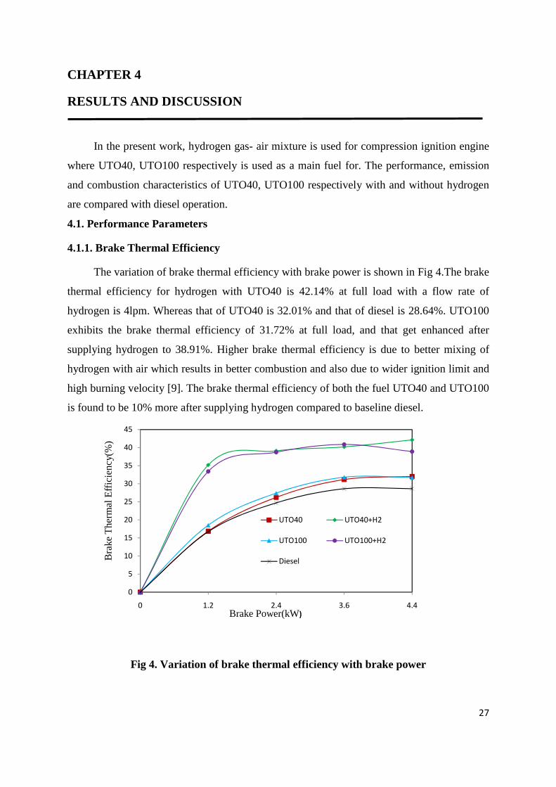
4.1.1. Brake Thermal Efficiency
The variation of brake thermal efficiency with brake power is shown in Fig 4.The brake
thermal efficiency for hydrogen with UTO40 is 42.14% at full load with a flow rate of
hydrogen is 4lpm. Whereas that of UTO40 is 32.01% and that of diesel is 28.64%. UTO100
exhibits the brake thermal efficiency of 31.72% at full load, and that get enhanced after
supplying hydrogen to 38.91%. Higher brake thermal efficiency is due to better mixing of
hydrogen with air which results in better combustion and also due to wider ignition limit and
high burning velocity [9]. The brake thermal efficiency of both the fuel UTO40 and UTO100
is found to be 10% more after supplying hydrogen compared to baseline diesel.
0
5
10
15
20
25
30
35
40
45
0 1.2 2.4 3.6 4.4
Bra
ke T
herm
al E
ffici
ency
(%)
Brake Power(kW)
UTO40 UTO40+H2
UTO100 UTO100+H2
Diesel
Fig 4. Variation of brake thermal efficiency with brake power

28
4.1.2. Brake Specific Energy Consumption
Fig 5. Shows the variation of brake specific energy consumption with the brake power.
The specific energy consumption of UTO40 and UTO100 with hydrogen induction is found
to be lower compared to UTO40 ,UTO100 without hydrogen and baseline diesel fuel. The
lower specific energy consumption is due to the better mixing of hydrogen with air,results in
complete combustion of the fuel[32]. The specific energy consumptionn of UTO40 with
hydrogen is found to be 8.5411 MJ/kW–hr which is lower compared to 11.2443MJ/kW-hr
for UTO40 without hydrogen at full load. The diesel shows the maximum energy
consumption at all the loads.
0
5
10
15
20
25
0 1.2 2.4 3.6 4.4
Bra
ke S
pe
cific
En
erg
y C
on
sum
ptio
n(M
J/kW
h)
Brake Power (kW)
UTO40 UTO40+H2
UTO100 UTO100+H2
Diesel
Fig 5. Variation of brake specific energy consumption with brake power
4.1.3 Exhaust Gas Temperature
The variation of exhaust gas temperature with brake power is shown in Fig 6. The
exhaust gas temperature of UTO40 with hydrogen is 365oC at full load while that of UTO40
is 325oC and that of diesel is 269.54oC while the exhaust gas temperature of UTO100 with
hydrogen is 375oC at full load while that of UTO100 is 360oC . The exhaust gas temperature
of UTO100 with hydrogen is more compared to UTO40 with and without hydrogen and also
with baseline diesel. The reason is may be due to high auto ignition temperature of hydrogen.
It requires high temperature to ignite. Therefore the residence time is more for the hydrogen.
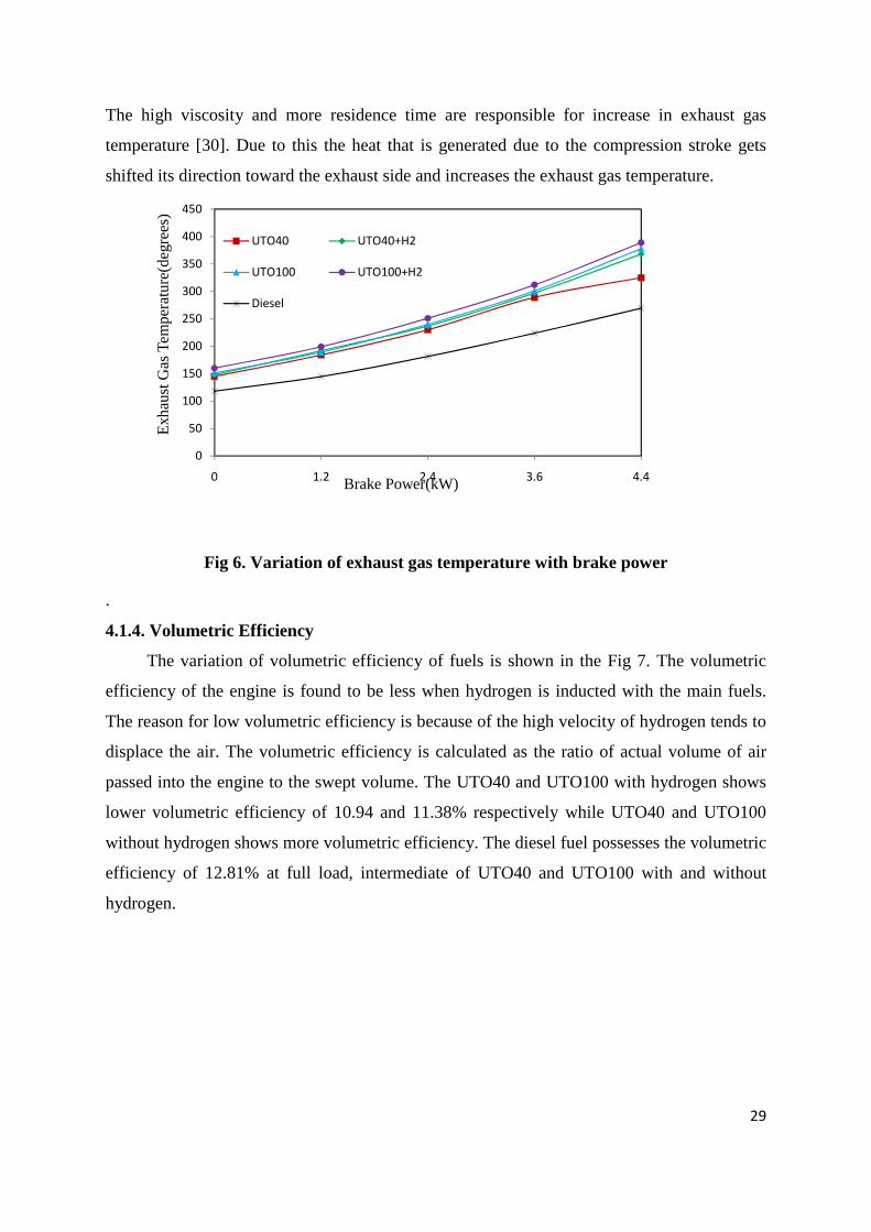
29
The high viscosity and more residence time are responsible for increase in exhaust gas
temperature [30]. Due to this the heat that is generated due to the compression stroke gets
shifted its direction toward the exhaust side and increases the exhaust gas temperature.
0
50
100
150
200
250
300
350
400
450
0 1.2 2.4 3.6 4.4
Exh
aust
Gas
Tem
pera
ture
(deg
rees
)
Brake Power(kW)
UTO40 UTO40+H2
UTO100 UTO100+H2
Diesel
Fig 6. Variation of exhaust gas temperature with brake power
.
4.1.4. Volumetric Efficiency
The variation of volumetric efficiency of fuels is shown in the Fig 7. The volumetric
efficiency of the engine is found to be less when hydrogen is inducted with the main fuels.
The reason for low volumetric efficiency is because of the high velocity of hydrogen tends to
displace the air. The volumetric efficiency is calculated as the ratio of actual volume of air
passed into the engine to the swept volume. The UTO40 and UTO100 with hydrogen shows
lower volumetric efficiency of 10.94 and 11.38% respectively while UTO40 and UTO100
without hydrogen shows more volumetric efficiency. The diesel fuel possesses the volumetric
efficiency of 12.81% at full load, intermediate of UTO40 and UTO100 with and without
hydrogen.
30
0
2
4
6
8
10
12
14
16
0 1.2 2.4 3.6 4.4
Volu
met
ric E
ffici
ency
( %
)
Brake Power(kW)
UTO40 UTO40+H2
UTO100 UTO100+H2
Diesel
Fig 7. Variation of volumetric efficiency with brake power
4.2. Emission Parameters
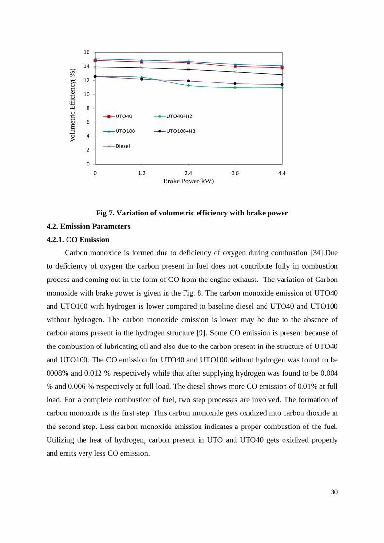
4.2.1. CO Emission
Carbon monoxide is formed due to deficiency of oxygen during combustion [34].Due
to deficiency of oxygen the carbon present in fuel does not contribute fully in combustion
process and coming out in the form of CO from the engine exhaust. The variation of Carbon
monoxide with brake power is given in the Fig. 8. The carbon monoxide emission of UTO40
and UTO100 with hydrogen is lower compared to baseline diesel and UTO40 and UTO100
without hydrogen. The carbon monoxide emission is lower may be due to the absence of
carbon atoms present in the hydrogen structure [9]. Some CO emission is present because of
the combustion of lubricating oil and also due to the carbon present in the structure of UTO40
and UTO100. The CO emission for UTO40 and UTO100 without hydrogen was found to be
0008% and 0.012 % respectively while that after supplying hydrogen was found to be 0.004
% and 0.006 % respectively at full load. The diesel shows more CO emission of 0.01% at full
load. For a complete combustion of fuel, two step processes are involved. The formation of
carbon monoxide is the first step. This carbon monoxide gets oxidized into carbon dioxide in
the second step. Less carbon monoxide emission indicates a proper combustion of the fuel.
Utilizing the heat of hydrogen, carbon present in UTO and UTO40 gets oxidized properly
and emits very less CO emission.
31
0
0.005
0.01
0.015
0.02
0.025
0.03
0.035
0 1.2 2.4 3.6 4.4
CO
Em
issi
on (
%)
Brake Power(kW)
UTO40 UTO40+H2
UTO100 UTO100+H2
Diesel
Fig 8. Variation of CO emission with brake power
At zero load the CO emission is found to be more and because of coarse spray
formation of main fuels at zero load and it decreases with the increase in load due to high
temperature achieved after combustion, CO get oxidized into CO2.
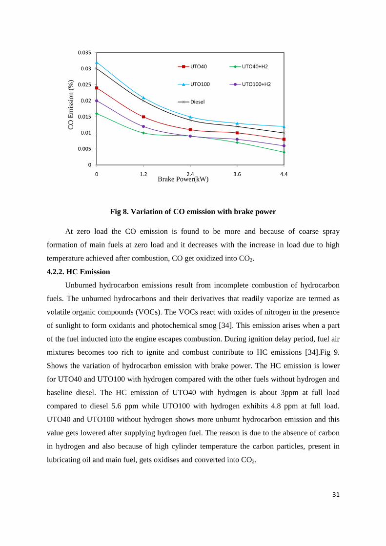
4.2.2. HC Emission
Unburned hydrocarbon emissions result from incomplete combustion of hydrocarbon
fuels. The unburned hydrocarbons and their derivatives that readily vaporize are termed as
volatile organic compounds (VOCs). The VOCs react with oxides of nitrogen in the presence
of sunlight to form oxidants and photochemical smog [34]. This emission arises when a part
of the fuel inducted into the engine escapes combustion. During ignition delay period, fuel air
mixtures becomes too rich to ignite and combust contribute to HC emissions [34].Fig 9.
Shows the variation of hydrocarbon emission with brake power. The HC emission is lower
for UTO40 and UTO100 with hydrogen compared with the other fuels without hydrogen and
baseline diesel. The HC emission of UTO40 with hydrogen is about 3ppm at full load
compared to diesel 5.6 ppm while UTO100 with hydrogen exhibits 4.8 ppm at full load.
UTO40 and UTO100 without hydrogen shows more unburnt hydrocarbon emission and this
value gets lowered after supplying hydrogen fuel. The reason is due to the absence of carbon
in hydrogen and also because of high cylinder temperature the carbon particles, present in
lubricating oil and main fuel, gets oxidises and converted into CO2.
32
0
2
4
6
8
10
12
14
16
18
20
0 1.2 2.4 3.6 4.4
HC
Eem
issi
on(p
pm)
Brake Power(kW)
UTO40 UTO40+H2
UTO100 UTO100+H2
Diesel
Fig 9. Variation of HC emission with brake power
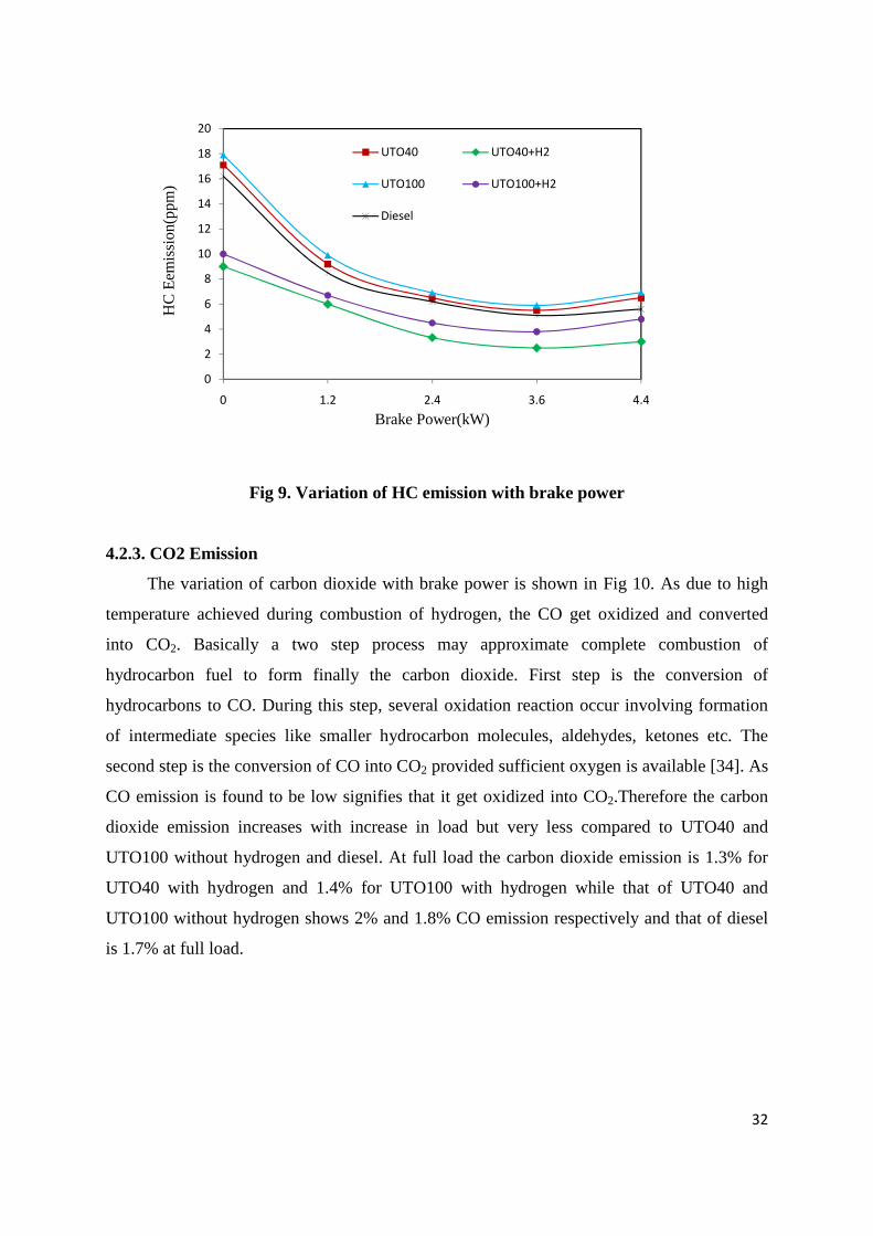
4.2.3. CO2 Emission
The variation of carbon dioxide with brake power is shown in Fig 10. As due to high
temperature achieved during combustion of hydrogen, the CO get oxidized and converted
into CO2. Basically a two step process may approximate complete combustion of
hydrocarbon fuel to form finally the carbon dioxide. First step is the conversion of
hydrocarbons to CO. During this step, several oxidation reaction occur involving formation
of intermediate species like smaller hydrocarbon molecules, aldehydes, ketones etc. The
second step is the conversion of CO into CO2 provided sufficient oxygen is available [34]. As
CO emission is found to be low signifies that it get oxidized into CO2.Therefore the carbon
dioxide emission increases with increase in load but very less compared to UTO40 and
UTO100 without hydrogen and diesel. At full load the carbon dioxide emission is 1.3% for
UTO40 with hydrogen and 1.4% for UTO100 with hydrogen while that of UTO40 and
UTO100 without hydrogen shows 2% and 1.8% CO emission respectively and that of diesel
is 1.7% at full load.
33
0
0.5
1
1.5
2
2.5
0 1.2 2.4 3.6 4.4
CO
2 E
mis
sion
(%)
Brake Power(kW)
UTO40 UTO40+H2
UTO100 UTO100+H2
Diesel
Fig 10. Variation of CO2 emission with brake power
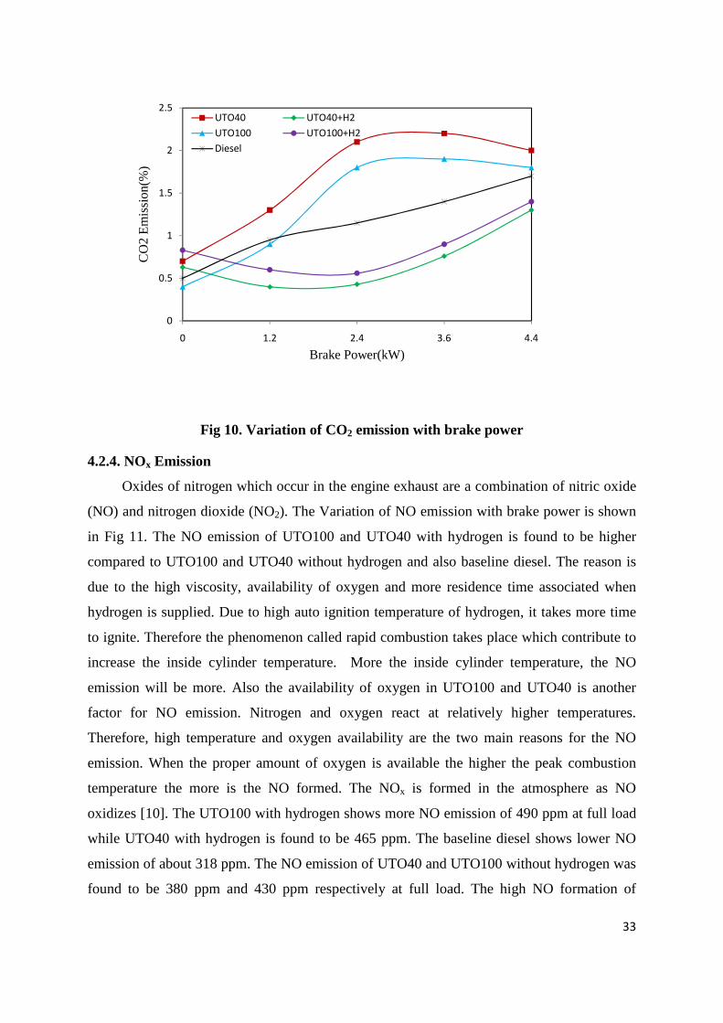
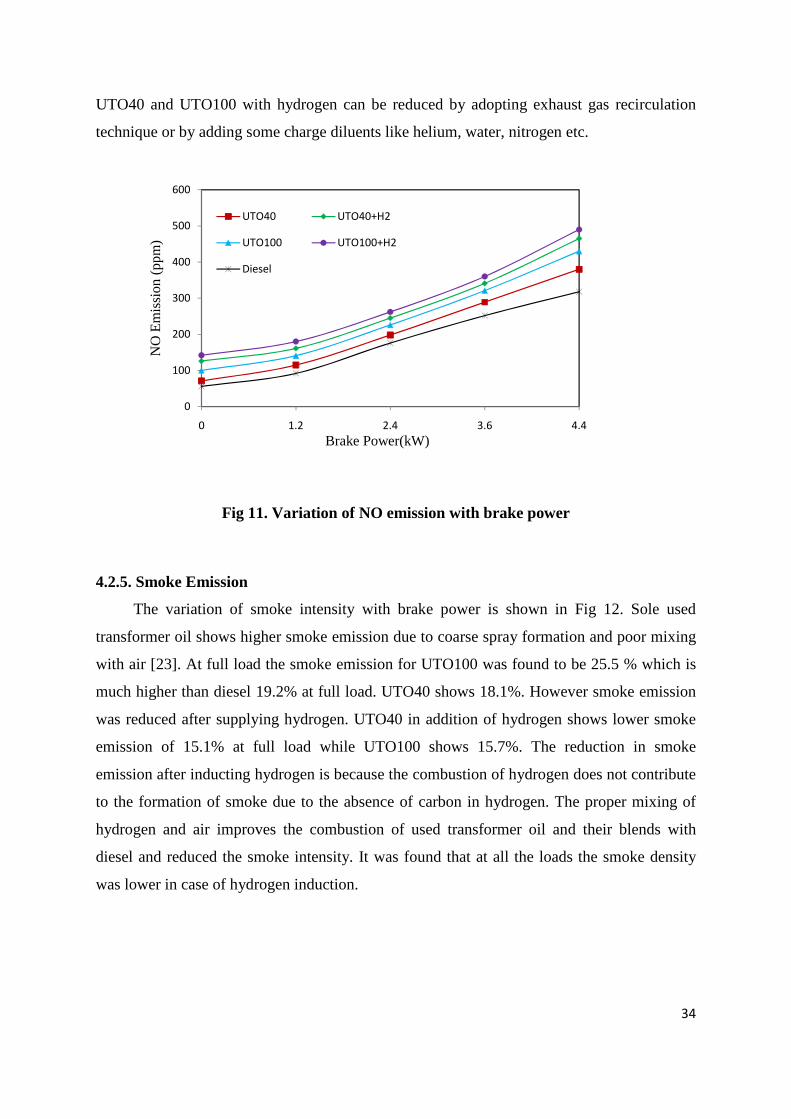
4.2.4. NOx Emission
Oxides of nitrogen which occur in the engine exhaust are a combination of nitric oxide
(NO) and nitrogen dioxide (NO2). The Variation of NO emission with brake power is shown
in Fig 11. The NO emission of UTO100 and UTO40 with hydrogen is found to be higher
compared to UTO100 and UTO40 without hydrogen and also baseline diesel. The reason is
due to the high viscosity, availability of oxygen and more residence time associated when
hydrogen is supplied. Due to high auto ignition temperature of hydrogen, it takes more time
to ignite. Therefore the phenomenon called rapid combustion takes place which contribute to
increase the inside cylinder temperature. More the inside cylinder temperature, the NO
emission will be more. Also the availability of oxygen in UTO100 and UTO40 is another
factor for NO emission. Nitrogen and oxygen react at relatively higher temperatures.
Therefore, high temperature and oxygen availability are the two main reasons for the NO
emission. When the proper amount of oxygen is available the higher the peak combustion
temperature the more is the NO formed. The NOx is formed in the atmosphere as NO
oxidizes [10]. The UTO100 with hydrogen shows more NO emission of 490 ppm at full load
while UTO40 with hydrogen is found to be 465 ppm. The baseline diesel shows lower NO
emission of about 318 ppm. The NO emission of UTO40 and UTO100 without hydrogen was
found to be 380 ppm and 430 ppm respectively at full load. The high NO formation of
34
UTO40 and UTO100 with hydrogen can be reduced by adopting exhaust gas recirculation
technique or by adding some charge diluents like helium, water, nitrogen etc.
0
100
200
300
400
500
600
0 1.2 2.4 3.6 4.4
NO
Em
issi
on (
ppm
)
Brake Power(kW)
UTO40 UTO40+H2
UTO100 UTO100+H2
Diesel
Fig 11. Variation of NO emission with brake power
4.2.5. Smoke Emission
The variation of smoke intensity with brake power is shown in Fig 12. Sole used
transformer oil shows higher smoke emission due to coarse spray formation and poor mixing
with air [23]. At full load the smoke emission for UTO100 was found to be 25.5 % which is
much higher than diesel 19.2% at full load. UTO40 shows 18.1%. However smoke emission
was reduced after supplying hydrogen. UTO40 in addition of hydrogen shows lower smoke
emission of 15.1% at full load while UTO100 shows 15.7%. The reduction in smoke
emission after inducting hydrogen is because the combustion of hydrogen does not contribute
to the formation of smoke due to the absence of carbon in hydrogen. The proper mixing of
hydrogen and air improves the combustion of used transformer oil and their blends with
diesel and reduced the smoke intensity. It was found that at all the loads the smoke density
was lower in case of hydrogen induction.
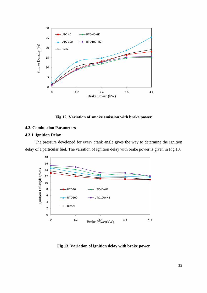
35
0
5
10
15
20
25
30
0 1.2 2.4 3.6 4.4
Sm
oke
Den
sity
(%
)
Brake Power (kW)
UTO 40 UTO 40+H2
UTO 100 UTO100+H2
Diesel
Fig 12. Variation of smoke emission with brake power
4.3. Combustion Parameters
4.3.1. Ignition Delay
The pressure developed for every crank angle gives the way to determine the ignition
delay of a particular fuel. The variation of ignition delay with brake power is given in Fig 13.
0
2
4
6
8
10
12
14
16
18
0 1.2 2.4 3.6 4.4
Igni
tion
Del
ay(d
egre
es)
Brake Power(kW)
UTO40 UTO40+H2
UTO100 UTO100+H2
Diesel
Fig 13. Variation of ignition delay with brake power
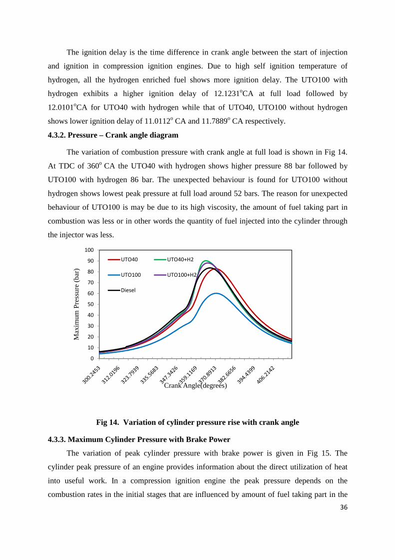
36
The ignition delay is the time difference in crank angle between the start of injection
and ignition in compression ignition engines. Due to high self ignition temperature of
hydrogen, all the hydrogen enriched fuel shows more ignition delay. The UTO100 with
hydrogen exhibits a higher ignition delay of 12.1231oCA at full load followed by
12.0101oCA for UTO40 with hydrogen while that of UTO40, UTO100 without hydrogen
shows lower ignition delay of 11.0112o CA and 11.7889o CA respectively.
4.3.2. Pressure – Crank angle diagram
The variation of combustion pressure with crank angle at full load is shown in Fig 14.
At TDC of 360o CA the UTO40 with hydrogen shows higher pressure 88 bar followed by
UTO100 with hydrogen 86 bar. The unexpected behaviour is found for UTO100 without
hydrogen shows lowest peak pressure at full load around 52 bars. The reason for unexpected
behaviour of UTO100 is may be due to its high viscosity, the amount of fuel taking part in
combustion was less or in other words the quantity of fuel injected into the cylinder through
the injector was less.
0
10
20
30
40
50
60
70
80
90
100
Max
imum
Pre
ssur
e (b
ar)
Crank Angle(degrees)
UTO40 UTO40+H2
UTO100 UTO100+H2
Diesel
Fig 14. Variation of cylinder pressure rise with crank angle
4.3.3. Maximum Cylinder Pressure with Brake Power
The variation of peak cylinder pressure with brake power is given in Fig 15. The
cylinder peak pressure of an engine provides information about the direct utilization of heat
into useful work. In a compression ignition engine the peak pressure depends on the
combustion rates in the initial stages that are influenced by amount of fuel taking part in the

37
premixed combustion that is governed by the delay period and also the mixture preparation
during the delay period [30]. Thus the fuel exhibits higher ignition delays possess peak
cylinder pressure.
40
50
60
70
80
90
0 1.2 2.4 3.6 4.4
Ma
xim
um
Pre
ssu
re (
ba
r)
Brake Power(kW)
UTO40 UTO40+H2
UTO100 UTO100+H2
Diesel
Fig 15. Variation of maximum cylinder pressure with brake power
Due to high self ignition temperature of hydrogen fuel, the mixture takes more time to
ignite. During this period, more charge gets accumulated inside the combustion chamber, due
to which rapid combustion takes place. The peak pressure is increased from 57 bars from zero
loads to 86 bars at full load for UTO40 with hydrogen. While the peak pressure for UTO100
with hydrogen is increased from 58 bars from zero loads to 88 at full load. The supply of
hydrogen shows more inside cylinder peak pressure. The unexpected behaviour is found at
full load for UTO100 without hydrogen showing decrease in peak cylinder pressure at full
load may be due to its high viscosity, less quantity of fuel gets admitted through injector.
4.3.4. Heat release Vs Crank angle
The variation of heat release with crank angle at full load is shown in Fig 16. It is found
that the heat release rate for hydrogen inducted fuel increases with increase in crank angle
.The heat release rate depends mainly on ignition delay, combustion rate and heat content of
the fuel. Due to the higher ignition delay for hydrogen inducted fuels, the rate of pressure rise
was also found to be higher. The maximum heat release rate for UTO40 with hydrogen
addition was found to be 74J/deg while that of UTO100 with hydrogen shows maximum heat
release rate of 63 J/deg. The lower value of UTO100 is due to less participation of fuel
quantity inside the combustion chamber because of high viscosity of UTO100. The injector
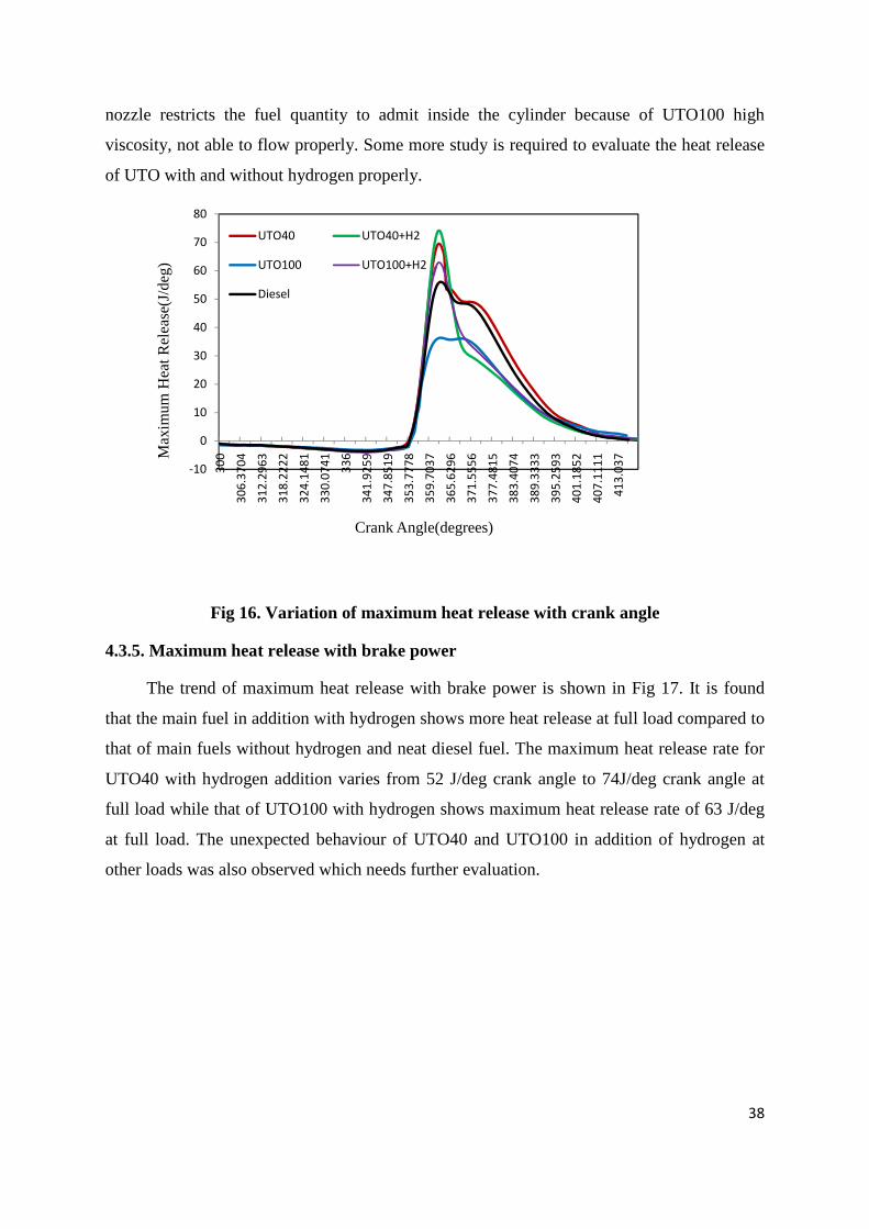
38
nozzle restricts the fuel quantity to admit inside the cylinder because of UTO100 high
viscosity, not able to flow properly. Some more study is required to evaluate the heat release
of UTO with and without hydrogen properly.
-10
0
10
20
30
40
50
60
70
803
00
30
6.3
70
4
31
2.2
96
3
31
8.2
22
2
32
4.1
48
1
33
0.0
74
1
33
6
34
1.9
25
9
34
7.8
51
9
35
3.7
77
8
35
9.7
03
7
36
5.6
29
6
37
1.5
55
6
37
7.4
81
5
38
3.4
07
4
38
9.3
33
3
39
5.2
59
3
40
1.1
85
2
40
7.1
11
1
41
3.0
37M
axim
um H
eat
Rel
ease
(J/d
eg)
Crank Angle(degrees)
UTO40 UTO40+H2
UTO100 UTO100+H2
Diesel
Fig 16. Variation of maximum heat release with crank angle
4.3.5. Maximum heat release with brake power
The trend of maximum heat release with brake power is shown in Fig 17. It is found
that the main fuel in addition with hydrogen shows more heat release at full load compared to
that of main fuels without hydrogen and neat diesel fuel. The maximum heat release rate for
UTO40 with hydrogen addition varies from 52 J/deg crank angle to 74J/deg crank angle at
full load while that of UTO100 with hydrogen shows maximum heat release rate of 63 J/deg
at full load. The unexpected behaviour of UTO40 and UTO100 in addition of hydrogen at
other loads was also observed which needs further evaluation.
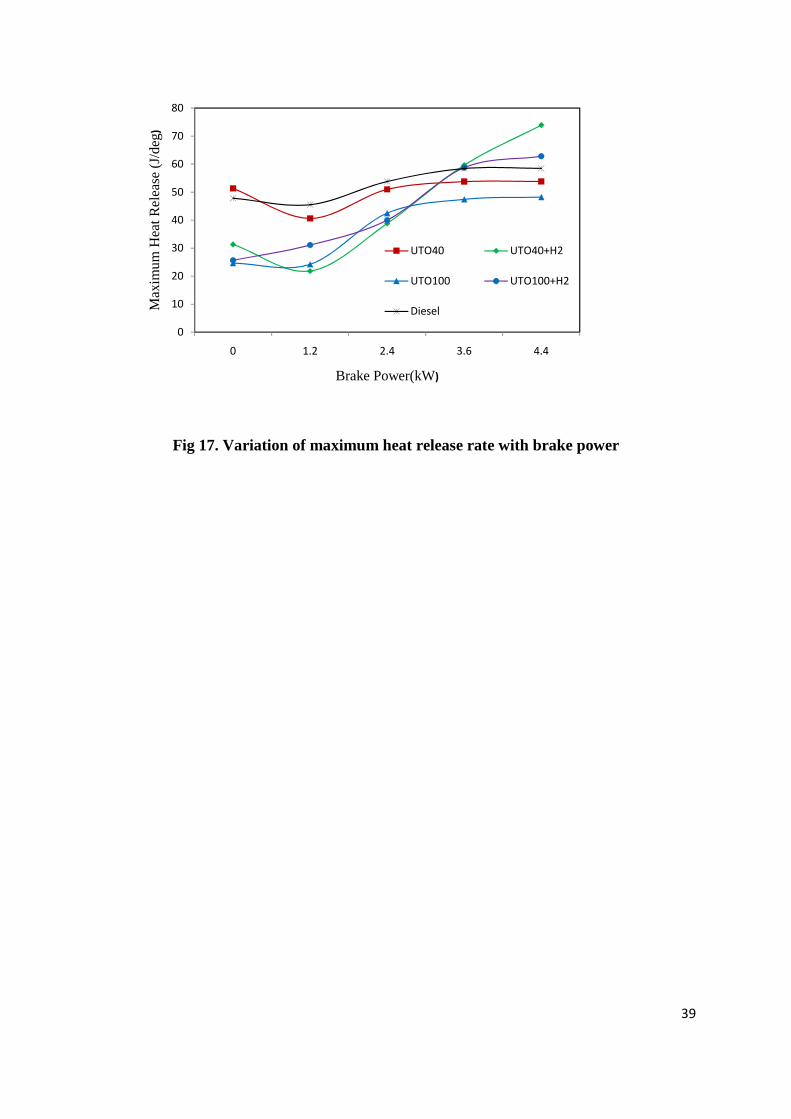
39
0
10
20
30
40
50
60
70
80
0 1.2 2.4 3.6 4.4
Max
imum
Hea
t R
elea
se (
J/de
g)
Brake Power(kW)
UTO40 UTO40+H2
UTO100 UTO100+H2
Diesel
Fig 17. Variation of maximum heat release rate with brake power

CHAPTER 5
SUMMARY

40
CHAPTER 5
SUMMARY
5.1. Conclusion
A single cylinder, four stoke, air cooled direct injection compression ignition engine
was operated successfully using hydrogen gas, supplying at a flow rate of 4 LPM and
inducting at a distance of 40 cm from the intake manifold. The performance, emission and
combustion parameters of the engine using UTO40 and UTO100 as a main fuel, with and
without hydrogen induction were obtained in the investigation are compared with the diesel
fuel. The following conclusions are drawn:
1. Experimental results shows UTO40 as the optimum blending compared to all other
blending proportion with diesel. The performance, emission and combustion characteristics
of UTO40 can be improved further by hydrogen induction along with air. Also with
UTO100, the engine was able to run but engine gives high vibration. So by inducting
hydrogen on UTO100, the engine was able to run smoother.
2. The brake thermal efficiency for both the main fuel inducted with hydrogen was found to
be high, UTO40 with hydrogen is 42.14% and UTO100 with hydrogen addition was 38.91
%, because of proper combustion and high burning velocity.
3. The brake specific energy consumption of UTO40 and UTO100 with hydrogen induction
was found to be lower 8.5411MJ/kWh and 9.2498 MJ /kWh respectively compared
to11.2443 MJ/kWh for UTO40 without hydrogen and 11.3803 MJ/kWh for UTO100
without hydrogen at full load.
4. The exhaust gas temperature of UTO40 with hydrogen is 365oC at full load while that of
UTO40 is 325oC and that of diesel is 269.54oC while the exhaust gas temperature of UTO100
with hydrogen is 375oC at full load while that of UTO100 is 361oC .
5. The carbon monoxide and hydrocarbon emission of UTO40 and UTO100 with hydrogen
induction was lower compared to diesel and UTO40 and UTO100 without hydrogen due to
the absence of carbon atoms present in the hydrogen structure. But the carbon dioxide
emission increases for UTO40 and UTO100 with hydrogen induction with the increase in
load but the concentration is very less compared UTO40 and UTO100 without hydrogen
induction.
6. The NO emission of UTO100 and UTO40 with hydrogen is found to be higher compared
to UTO100 and UTO40 without hydrogen and also diesel because of high temperature
41
achieved during combustion when hydrogen was admitted. The UTO100 with hydrogen
shows more NO emission of 490 ppm at full load while UTO40 with hydrogen is found to
be 465 ppm. The diesel shows lower NO emission of about 318 ppm. The NO emission of
UTO40 and UTO100 without hydrogen was found to be 380 ppm and 430 ppm respectively
at full load.
7. The smoke level was found to be low at all loads for hydrogen enriched fuels because of
proper mixing of hydrogen and air and proper combustion. At full load the smoke emission
for UTO100 and UTO40 was found to be 25.5% and 18.1% respectively which gets reduced
after hydrogen induction to 15.1% for UTO40 and 15.7% for UTO100 at full load.
8. The UTO100 with hydrogen exhibits a higher ignition delay of 12.1231oC at full load
followed by 12.0101oC for UTO40 with hydrogen while that of UTO40, UTO100 without
hydrogen shows lower ignition delay of 11.0112o C and 11.7889o C respectively. The higher
ignition delay for hydrogen inducted fuel is due to high self ignition temperature of hydrogen
and more residence time.
9. Due to high self ignition temperature of hydrogen fuel, and more charge accumulation
inside the combustion chamber, hydrogen inducted fuel possess higher peak pressure and
high rate of heat release. Due to the high viscosity of UTO100, less quantity of the fuel gets
actually admitted results lower heat release rate and also maximum cylinder pressure. More
study is required to evaluate the combustion behaviour of the engine inducted with hydrogen.
5.2. Scope for future work
Hydrogen seems to be the future fuel for the automobile but more works are needed on
the field of its production, storage and transportation. Also the safety of hydrogen fuelled
engine is also an important matter of concern.
As far as the emission is concerned, only NOx emission is found to be high. The
excessive work is required to reduce the NOx emission from the engine. Also at higher flow
rate of hydrogen, the engine starts vibrating, so still scope is there to implement new
techniques, so that the engine could perform even better at a higher flow rate,
A detailed research on Used Transformer Oil is also required. Especially the neat used
transformer oil (UTO100) needs a high attention of researchers. The unexpected combustion
behaviour of UTO100 and UTO100 with hydrogen still needs to be evaluated deeply.

42
Sole used transformer oil after filtering is utilized on compression ignition engine.
Scope is there to work on distilled used transformer oil (i.e. used transformer oil after
distillation). It is expected that after distillation, the viscosity of the used transformer oil will
get reduce and that may enhance the performance of the engine. The above experimental
investigation was carried out at a fixed injection timing and injection pressure. The scope is
there to find out the optimized injection timing by adding or removing the shim near fuel
pump and also to optimize the nozzle injection pressure. After optimizing all those
parameters, hydrogen at different flow rate is need to be supply and to obtain the optimize
flow rate of hydrogen. This work is under the progress.
More attention is required to understand the unexpected combustion behaviour of UTO
with and without hydrogen induction. Used transformer oil also needs special attention,
because UTO has all desirable properties to be treated as fuel.

LIST OF REFERENCES
43
LIST OF REFERENCES
[1]V.M. Domkundwar,”A course in internal combustion engines” Dhanpat Rai publication, ISBN 81-7700-003-0,pp 22.22-22.32.
[2]G.D. Rai,”Non conventional energy sources” Khanna publishers, ISBN 81-7409-073-
8, pp 315-615. [3]R.B. Gupta,”Hydrogen fuel-Production, storage and transportation” CRC Press publication
Taylor and Francis group, ISBN 978-1-4200-4575-8, pp 1-12. [4]V.Ganeshan,”A textbook on Internal Combustion Engines” 2nd edition, ISBN 0-07-
049457-6, pp 220-223. [5] L.E. Reid, D.A. Gudelis, Low Pour Point Transformer Oils from Paraffinic Crudes, US
Patent 4, 018, 666, and 1977 [6] Tulstar products, inc. material safety data sheet Transformer Oil, Type II, and TS-3487.
[7] P.Behera, S.Murugan,”combustion, performance, and emission parameters of used transformer oil and its diesel blends in a DI diesel engine” Fuel manuscript no: JFUE-D-11-00382,2011.
[8]L.M. Das,”Fuel induction techniques for a hydrogen operated engine” Int. J. Hydrogen
Energy, Vol. 15, pp 833-842,1990. [9]N.Saravanan, G.Nagarajan, S. Narayanswamy,”An experimental investigation of DI diesel
engine with hydrogen fuel”, Renewable Energy 33, pp 415-421, 2008. [10]N.Saravanan, G.Nagarajan, K.M.Kalaiselvan, C.Dhanasekaran,”An experimental
investigation on hydrogen as a dual fuel for engine system with exhaust gas recirculation technique” Renewable Energy 33, pp 422-427, 2008.
[11]N. Saravanan, G. Nagarajan, “Performance and emission studies on port injection of
hydrogen with varied flow rates with diesel as an ignition source” Applied Energy, Vol.87, pp 2218-2229, 2010.
[12]N. Saravanan, G. Nagarajan, G. Sanjay, C. Dhanasekaran, K.M. Kalaiselvan, “Combustio
n analysis on a DI diesel engine with hydrogen in dual fuel mode”, Fuel 87,pp 3591-3599, 2008.
[13]Li Jing-Ding, Lu Ying-Qing and Du Tian-Shen, ”Improvement on the combustion of a
hydrogen fuelled engine” Int. J. Hydrogen Energy, Vol 11.No.10,pp 661-668, 1986.
44
[14]J.M.Gomes Antunes, R. Mikalsen, A.P. Roskilly, “An experimental study of a direct injection compression ignition hydrogen engine” Int. J. Hydrogen Energy Vol 34,pp 6516-6522,2009.
[15]L.M. Das, “Hydrogen engines: A view of the past and a look into the future” Int. J.
Hydrogen Energy, Vol 15, pp 425-443, 1990. [16]L.M. Das, “Safety aspects of a hydrogen fuelled engine system development” Int. J.
Hydrogen Energy, Vol 16, pp 619-624,1991. [17]L.M. Das, “Exhaust emission characterization of hydrogen operated engine system:
Nature of pollutants and their control techniques” Int. J. Hydrogen Energy, Vol 16,pp 765-775,1991.
[18]H.B. Mathur, L.M. Das and T.N. Patro, “Hydrogen fuelled diesel engine: Performance
improvement through charge dilution techniques” Int. J. Hydrogen Energy, Vol. 18,pp 421-431,1993.
[19]H.B. Mathur, L.M. Das and T.N. Patro, “Effects of charge diluents on the emission
characteristics of a hydrogen fuelled diesel engine” Int. J. Hydrogen Energy, Vol. 17, pp 635-642,1992.
[20]L.M. Das ,”Hydrogen-Oxygen reaction mechanism and its implication to hydrogen
engine combustion” Int. J. Hydrogen Energy, Vol. 21, pp 703-715,1996. [21]KS Varde, LK Varde,”Reduction of soot in diesel combustion with hydrogen and
different H/C gaseous fuels” 5th world hydrogen enrgy,Toronto,Canada,1984. [22]T. Lakshmanan, G.Nagarajan,”Experimental Investigation on dual fuel operation of
acetylene in a DI diesel engine” Fuel processing technology, Vol 91, pp 496-503, 2010. [23]M. Senthil Kumar, A. Ramesh, B. Nagalingam, ”Use of hydrogen to enhance the
performance of a vegetable oil fuelled compression ignition engine” Int. J. Hydrogen Energy 28 , pp 1143-1154, 2003.
[24]J.Nazar, A.Ramesh and B.Nagalingam, ”Experimental investigation on the performance of karanja oil-hydrogen dual fuel engine” Proceedings of the 19th National Conference on I.C. Engines and Combustion, Annamalai University, Chidambaram, pp 131-136, 2005.
[25]G.Sankaranarayanan,J.Jayaraj,N.Saravanan,K.Jeyachandran,”Performance and emission studies on DI diesel engine using madhuca indica oil and hydrogen as dual fuel” Proceedings of the 19th National Conference on I.C Engines and Combustion, Annamalai university,Chidambaram, pp 83-86, 2005.
[26]G.Nagarajan, A.N. Rao, and S.Renganarayanan,”Emission and Performance characteristi
cs of neat ethanol fuelled DI diesel engine” International Journal of Ambient Energy, Vol 23, pp 149-158, 2002.

45
[27]T.Lakshmanan and G.Nagarajan,”Experimental investigation of timed manifold injection of acetylene in direct injection diesel engine in dual fuel mode” Energy, Vol 35, pp 3172-3178.
[28]R.G.Papagiannakis,C.D.Rakapoulos, D.T. Hountalas,D.C.Ralapoulos,”Emission characte
ristics of high speed , dual fuel ,compression ignition engine operating in a wide range of natural gas/diesel fuel proportions” Fuel, Vol 89, pp 1397-1406,2010.
[29]Seung Hyun Yoon and Chang Sik Lee,” Experimental investigation on the combustion
and exhaust emission characteristics of bio gas – biodiesel dual – fuel combustion in a CI engine” Fuel Processing Technology, pp 1-9, 2011.
[30]M.Senthil Kumar, A.Ramesh and B.Nagalingam,”Complete vegetable oil fuelled dual
fuel compression ignition engine” SAE 2001-28-0067. [31]G.A.Rao, A.V.S. Raju, K. Govinda Rajulu and C.V. Mohan Rao,”Performance
evaluation of a dual fuel engine(Diesel + LPG)” Indian Journal of Science and Technology, Vol 3, pp 235-237, 2010.
[32]Siebers DL, “Hydrogen combustion under diesel engine conditions” Hydrogen energy,
23, pp 363-71, 1998. [33] J.B. Holman, Experimental Techniques for Engineers, McGraw Hill, 1988. [34]B.P.Pundir,”A textbook of Engine Emissions-pollutant formation and advances in control
technology” Narosa publication, ISBN 978-81-7319-819-9, pp 2-40.

46
RESEARCH PAPER PUBLISHED
CONFERENCE
Abhash Jaiswal, R.Prakash and S.Murugan,”Feasibility of using hydrogen fuel in CI engine”, at International conference on renewable energy, 2011 Jaipur on 17-21 January 2011.
JOURNAL UNDER REVIEW
Abhash Jaiswal, Bhupendra kumar Chandrakar, Pritinika Behera and S.Murugan,”Effect of hydrogen induction on performance and emission behaviour of compression ignition engines”, International Journal of Green Energy.IJGE-2011-0113.