specialized television engineering
TRANSCRIPT

SPECIALIZED
TELEVISION ENGINEERING
TELEVISION TECHNICAL ASSIGNMENT
OHM'S AND KIRCHHOFF'S LAWS AND BRIDGE CIRCUITS
Copyright 1948 by
Capitol Radio Engineering Institute
Washington, D. C.
I 709D I
www.americanradiohistory.com

OHM'S AND KIRCHHOFF'S LAWS: BRIDGE CIRCUITS
FOREWORD
This assignment is, without question, one of the most im-
portant in the entire course because it deals with fundamental re-
lationships between current, voltage and impedance. The term im-
pedance is used advisedly instead of resistance because resistance
is only a special type of impedance.
Ohm's Law, E = IZ, Z = E/I, I = E /Z, is the basic law of
electricity and like most basic laws is remarkably simple. It is
actually astounding, however, how many radiomen do not really know
how to apply it to circuit analysis. Such work is taken up in great
detail in this assignment. Although short and simple means have
been developed for the solution of many complex circuits, a thorough
understanding of Ohm's Law is essential to the analysis of any type
of electrical circuit.
Kirchhoff's Laws extend the applications of Ohm's Law and permit the more ready solution of complex circuits and networks.
Here will be used some of the special applications of algebra studied
in an earlier assignment.
Bridge Circuits are found throughout radio, one of the
most important applications being in measuring devices. The simplest
type is the Wheatstone Bridge used for d.c. measurement of resistance.
By substitution of L or C in place of R for certain elements, a
bridge may be used to measure inductance or capacity. By elaborate
refinements in construction and shielding, bridges may be used for
measurements at high radio frequencies. Bridge circuits are used as
neutralizing elements in R.F. amplifiers and as frequency stabilizing
devices in R.F. oscillators, and in numerous other applications.
In this assignment only the basic principles and fundamental
applications of bridges will be discussed. The various uses of the
bridge circuit will be taken up in detail in later assignments. A
thorough understanding of this assignment is a must.
E. H. Rietzke,
President.
www.americanradiohistory.com

- TABLE OF CONTENTS -
TELEVISION TECHNICAL ASSIGNMENT
OHM'S AND KIRCHHOFF'S LAWS AND BRIDGE CIRCUITS
Page
FUNDAMENTAL THEORY 1
OHM'S LAW 1
SERIES CIRCUIT i
PARALLEL CIRCUIT 2
SERIES- PARALLEL COMBINATIONS 5
GENERATED AND TERMINAL VOLTAGE 7
TWO SIMPLE RUDES 10
APPLICATIONS TO RADIO 12
SERIES -DROPPING RESISTORS 1
METER SHUNTS 14
VOLTAGE MULTIPLIERS 16
OHMMETERS 17
KIRCHHOFF'S LAWS 26
VOLTAGE -DIVIDER CIRCUITS 26
NETWORK SOLUTIONS 32
A THIRD NETWORK EXAMPLE 36
STAR- AND DELTA -CONNECTED NETWORKS 37
BRIDGE CIRCUITS 41
SLIDE-WIRE BRIDGE i
47
RESUME 48
www.americanradiohistory.com

TELEVISION TECHNICAL ASSIGNMENT
OHM'S AND KIRCHHOFF'S LAWS AND BRIDGE CIRCUITS
FUNDAAdFNFAL THEORY
It is assumed that every stu-
dent at this point is more or less
familiar with the most fundamental of all electrical formulas, Ohm's
Law. It is believed, however, that
a thorough review of the principles
involved in Ohm's Law is the logi-
cal step in progressing from the study of mathematics to the use of mathematics in the more complex electrical calculations.
Ohm's Law states, in a few words, the fundamental relation-
ship existing between the current,
voltage, and impedance of a cir-
cuit. In the simpler calculations
involving Ohm's Law the impedance
of a circuit is usually its re-
sistance, this being always the
case in a direct current circuit. In alternating current computa- tions the applications of this law become more complex, but fun- damentally the statement of the law is correct, the word "Resist- ance", however, being replaced by
"Impedance ". OHM'S LAW. -Ohm's Law states
that the current in a circuit varies
directly as the voltage and inverse-
ly as the resistance of the circuit.
This is ordinarily stated in
the form of an equation, the three
arrangements of the equation being
as follows:
I = E/R R = E/I E = IR
When this equation is to be used in circuits that are not com-
posed entirely of resistance, R will be replaced by Z. Z in turn will be
made up of resistance and inductive
or capacitive reactance, or both. The circuit may be a simple series
circuit, a simple parallel cir- cuit, or some more or less complex
circuit containing both series and
parallel members.
According to the statement of Ohm's Law, if the voltage and re- sistance are known, the current in
the circuit may be calculated by dividing the voltage by the resist-
ance in ohms, and the answer will
be an expression of the current in
amperes.
The other two equations ex- pressing Ohm's Law may be solved in an equally simple manner.
SERIES CIRCUIT.-The next rule is that expressing the im- pedance of a series circuit. This
rule states that the impedances of a series circuit add. If the im-
pedances are such that they have
identical effects on the phase re-
lations of the current and voltage of the circuit, such as two or more
pure resistances, two or more per-
fect inductances, two or more per-
fect capacities, or two or more combinations of' the above in which
the angles of lead or the angles of lag are identical, the addition
of the impedances will be arith- metical. If the constants making up the impedances are not such that their effects on the phase relations of current and voltage are identical, the addition will be vectorial. In this discussion circuits containing only resist- ance will be considered, thus no vector addition will be encountered
here, but it will be discussed in detail in later assignments.
A case of arithmetical addi-
www.americanradiohistory.com

2 OHM'S AND KIRCHHOFF'S
tion of resistances in series is
shown in Fig. 1, where R1 equals
50 ohms and R2 equals 50 ohms. Thq
total resistance, the two being in
Fig. 1. -- Resistances in series.
series, is equal to R1 + R2, or
100 ohms. If it is assumed that the voltage of the battery is 200 volts, as indicated by V, and Ohm's
Law is applied, the current in the
circuit will be indicated by the
ammeter A, and will be equal to
E/R = 200 /100 = 2 amperes. To find the voltage drop across
one of the resistors, for example
R2, another statement of the equa-
tion of Ohm's Law, E = IR, is used.
The resistance of R2 is 50 ohms;
the current through R2 is 2 am-
peres; the voltage drop across this resistance is then 50 x 2 =
100 volts.
If the voltage of the battery
is unknown but the total resist-
ance of the circuit and the cur-
rent as indicated by ammeter A are
known, the voltage of the battery
may be found by the same method. The battery voltage is equal to
the total resistance of the cir-
LAWS AND BRIDGE CIRCUITS
cuit in ohms times the current in
amperes. In this case suppose am-
meter A indicates 3.6 amperes. The
battery voltage will be 3.6 X 100 =
360 volts. (The arrow in Fig. 1
indicates the direction of electron
movement.)
This relation between currents
and voltages in a series circuit exists regardless of the number or
the values of the resistances. The
total resistance is equal to the sum
of all the individual resistances, and the current is equal to the total voltage divided by the total
resistance. The voltage drop across
any individual resistor is equal to
the value of that resistance in ohms
times the current flow in amperes through the resistor.
Two cardinal points to remember
when applying Ohm's Law to a series
circuit are:
1. The current is the same in
all parts of a. series circuit.
2. If the law is applied to
any part of the circuit, only the E,
I, and R values associated with that particular part of the cir- cuit should be used.
PARALLEL CIRCUIT. -The gener- al expression of Ohm's Law for par-
allel circuits states:
(a) The voltage across any number of résistances in parallel is the same across all the individu-
al resistances.
(b) The current through each
resistor is equal to the voltage divided by the resistance of the
individual resistor.
(c) The current in the ex-
ternal circuit is equal to the sum
of the currents through the in-
dividual resistances. The current through each branch
of a parallel circuit is equal to
the applied voltage divided by the
www.americanradiohistory.com

FUNDAfi ENTAL THEORY 3
resistance of that branch. A vari- ation of the resistance of any one branch of the parallel circuit has
no effect on the current in any oth-
er branch of the circuit so long as
B
Fig. 2. -- Resistances in parallel.
the voltage across the combination
is held constant.
An exemple of the simple par-
allel circuit is shown in Fig. 2.
Resistors R1 and R2 are in par- allel (as indicated by the common connections A and B) across the
same battery voltage. Assume that
the applied potential is 100 volts.
The current I in R1 is equal to
100 volts divided by the resist- ance of R1 or 100/50 = 2 amperes. The current I2 in R2 is found in a similar manner and is equal to 100/12.5 = 8 amperes. Since the current in the external circuit is equal to the sum of the cur- rents in the individual branches,
the total battery current It,
as indicated by A, is 2 + 8 = 10
amperes. In algebraic form It =
Il + I2.
Ohm's Law states that the
total resistance of a circuit is
equal to the applied voltage divided
by the total current, so the re-
sistance of the parallel combina- tion must be equal to 100/10 = 10
ohms. It will be observed that the
total resistance is less than the
resistance of either branch. In
fact, in any parallel circuit con -
taining only resistance, the total
resistance of the circuit will al- ways be less than that of any in-
dividual branch.
The method of computing the value of the total resistance as
described above may be used. This
method requires the calculation of
the current in each branch, the addition of all the individual currents, and the division of the
sum of the currents into the known
or assumed voltage. This method is extensively used in complex al- ternating current problems in which
the currents and voltages are out of phase by various angles. These
will be taken up in following as-
signments on parallel and series -
parallel circuits.
A fundamental method of deal- ing with parallel circuits is de-
veloped in the following paragraphs.
It is based on the fact that the re-
sistance of any circuit is independ- ent of the circuit voltage. Consid-
er the circuit of Fig. 3. The re-
sistance of R1, R2, and R3 in par-
allel is independent of the volt- age of the battery. This means that any value of E may be assumed to be connected across the par- allel combination, and it is de-
sired to find the total R. As- sume that the battery potential is 1 volt. Then the currents I1, I2, and I3 are respectively,
www.americanradiohistory.com

4 OHM'S AND KIRCHHOFF'S LAWS AND BRIDGE CIRCUITS
Fig. 3.- -Three resistances in par-
allel.
I =-1- 2
R 2
I 3 3 R
3
The total current from the bat- tery is,
I = I + I __ + I = 1+1__ +__1_. t 1 2 3 R1 R2 R3
But Rt = E/I where E = 1 volt (assumed). So
R - 1 t
1 R ++R
1 2 3
Therefore, the total resist- ance of a parallel circuit is equal to the reciprocal of the sum of the reciprocals of the in- dividual branches. To solve any
parallel combination, a.c. or d.c.,
where only the impedance of the branches are known, assume a volt-
age connected across the combina- tion, calculate the branch cur- rents, and add to find the total
current It. The assumed voltage divided by the total current gives
the effective impedance of the combination. The importance of
This method of solution will be- come apparent in the study of a.c. circuits.
The reciprocal of a number is 1 divided by that number. The re- ciprocal of R1 is equal to i/R1. The reciprocal of resistance is called the conductance. The con-
ductance of a circuit is an ex-
pression of the ease with which current can flow, in contrast with the resistance which is defined as
the opposition to current flow. The
symbol for conductance is G. G =
1 /R. In the case of several re-
sistances in parallel the total con-
ductance will equal G1 + G2 + G3,
etc. Since G = 1 /R, the total conductance will be: 1/R1 + 1/R2
+ 1/R3, etc. The unit of conduct- ance is the mho (ohm spelled back- wards), and 1 mho is the recipro- cal of 1 ohm. Another definition is: the conductance of a resist- ance unit in mhos is numerically equal to the current in amperes which would flow through the unit if 1 volt were impressed across it.
If the conductance is equal to
the reciprocal of the resistance, then the resistance must be equal to the reciprocal of the conductance, 1 /G. The total resistance of the circuit must be equal to the re-
ciprocal of the total conductance.
R = 1/G
G = G1 + G2 ....
Therefore,
R = 1 G1 + G2 ....
But
GI = 1/R1 and G2 = 1/R2
Therefore, R = 1_
4_1_ R
www.americanradiohistory.com

FUNDAMENTAL THEORY 5
By simplifying the above formu-
la (see assignment on algebra), the
following is obtained:
R = R1 R2
R1 R2
which means the total resistance of two resistors in parallel is
equal to their product divided by their sum. The reciprocal formula is preferred when the cir-
cuit has three or more resistors in parallel, whereas the product over sum method has the advantage
of simplicity when only two re-
sistors are involved.
Using the values given in
Fig. 2,
or
R = 1 = 1 1 + i .02 + .08 50 12.5
- 1 = 10 ohms .1
R =50 x12.5_63= 10 ohms 50 + 12.5 62.5
This agrees with the answer ob- tained by the current method of computation.
SERIES- PARALLEL COMBINA- TIONS. -Fig. 4(A) is an example of a series circuit in which one of the series elements consists of a parallel combination of two resistors, 12.5 and 50 ohms, re-
spectively. The other series ele-
ment (R1) has a resistance of 50 ohms. Although this circuit con- tains a parallel combination of resistors, it is essentially a
series circuit and must be handled
as such.
It is first necessary to solve
the parallel combination in order that its equivalent series resistance
may be obtained. This is done as
shown in the preceding problem.
R 50 x 12.5 _ 10 ohms P 50 + 12.5
The equivalent series circuit is shown in Fig. 4(B). RP indicates
the parallel resistance of R2 and
R3. 3
The total resistance is now
equal to R1 + R = 50 + lU = 60 ohms.
Assume that the battery voltage is
(A)
R2 /2.5n
(B)
Fig. 4. -- Combination of resistances
in series and in parallel.
360 volts. Ammeter A will indicate
the total line current It of 360/60 = 6 amperes. To find the
current in each branch of the par-
www.americanradiohistory.com

6 OHH'S AND XIRCHHOFF'S
allel combination it is first neces-
sary to find the voltage drop across
the parallel portion of the circuit.
As it is one element of the series
resistance, the voltage across RP
will be equal to the product of the
value of its equivalent series re- sistance, 10 ohms, and the total current, 6 amperes, or 60 volts.
With a common potential of 60
volts across the parallel combina-
tion, the current through R2 will
equal E /R2 = 60/12.5 = 4.8 am-
peres. ¶he current in R9 will equal
E /R = 60/50 = 1.2 amperes. The
total current, It, is 4.8 + 1.2 =
6 amperes, as previously calcula-
ted. If the parallel combination
had contained more than two re-
sistors, a similar solution would
have applied. Fig. 5 is an example of a par-
allel combination in which one of
Fig. 5. -- Series -parallel combina-
tion in which one of the parallel
resistors and the battery voltage
are unknown.
the parallel resistors and the battery voltage are unknown. The
resistance of the single series element, R9, is 10 ohms; the resist-
LAWS AND BRIDGE CIRCUITS
ance of one parallel resistor, R2, is 20 ohms; the series line cur- rent, It, is 4 amperes; and the current I9 through the 20 -ohm resistor, R2, is 1 ampere. It is required to find the total cir-
cuit resistance, the battery volt- age, the resistance 'f R1, and the
current through R1. First, solve the parallel com-
bination. One branch of this com- bination (R2) has a resistance of 2D ohms; the current through R2 is 1 ampere; the voltage drop across
the resistor is I2 R2 = 1 x20 =
a) volts. Since the voltage across all branches of a parallel circuit
are equal, the voltage across R1 also equals 20 volts.
The total current through the circuit, as indicated by At, is 4 am-
peres. 1 ampere flows through R2, the 20 -ohm branch; the other 3 amperes must pass through R1. Since the voltage across R1 is 20
volts and the current through it is 3 amperes, R must equal E /I = 20/3 = 6.67 ohms.
v 1
The resistance of the parallel combination can now be found.
R R1R2 _ 6.67 x 20 _ 5 ohms p R + Ra + 20
1 s
The total resistance of the cir-
cuit is equal to Rp + R9 = 5 + 10 =
15 ohms.
The voltage of the battery is equal to the product of the total resistance and the total line cur- rent, or ItR = 4 x 15 = 60 volts.
This will be indicated by V. So
far we have considered the battery
as a source of voltage which is in-
dependent of the current drain and has no internal resistance. This will be clarified shortly.
Very complex combinations of
resistance may be solved by the
www.americanradiohistory.com

FUNDAMENTAL THEORY 7
logical application of Ohm's Law and the rules governing series and
parallel circuits similar to those
illustrated above. In the solu-
tion of a complex circuit care must be taken to use only values of E, I, and R that apply to the par-
ticular part of the circuit under
consideration. GENERATED AND TERMINAL VOLT -
AGE.-At this point it will be of value to discuss a matter that is
often puzzling to the student -name- ly, the generated and terminal volt- age of an electrical source of en- ergy. The source may be a rotating
machine, a thermoelectric generator,
a battery, etc. In any case the
source must permit the same current to
pass through it that it feeds to the
external load, just as a water pump
must pass the water it pumps through
the rest of the system. The elec-
trical source, like the water pump,
may offer internal friction or re-
sistance to the flow of current, or
more generally, it may have internal
impedance. Thus, not only does an elec-
trical source generate a voltage which forces the electrons around the closed circuit, but it also may
develop an IR voltage drop owing to its internal resistance, and
this voltage drop must be subtrac-
ted from the generated voltage to
give the net or terminal voltage appearing across the generator's terminals, and available for forc-
ing the current through the ex-
ternal part of the circuit. It
is convenient to represent an actual generator having internal resistance in the form of two components as shown in Fig. 6
within the dotted line rectangle:
(a) An ideal generator (shown
as a battery) having no internal
resistance, and generating a volt-
age, e6, and
(b) A resistance R0 repre-
senting the internal resistance of the actual generator. (In the
general case R0 would be replaced
by an impedance Z6.) The combination is shown feed-
ing an external load RL, when the
eL
Fig. 6.-- Representation of an actual
generator by an ideal generator de-
veloping a generated voltage, eG,
and having an internal resistance,
RG, in series with an external load.
switch S is closed. The current i
that flows produces an internal voltage drop i RG in the generator,
and an external voltage drop 'eL
=
i RL across the load. It is clear
from the figure that the sum of the
voltage drops must equal the gen-
erated voltage, or
eG = i R0 + RL
Factoring out i on the right -hand side, there is obtained
eG = i (RG + RL)
Dividing both sides by the factor
(RG + RL), there is obtained
www.americanradiohistory.com

8 OHM'S AND IIRCHHOFF¡S LAWS AND BRIDGE CIRCUITS
This shows that the current de- pends not only upon the generated
voltage, e0, and the external load, RL, but also upon the internal re-
sistance, R6, of the generator. It
is also clear from the figure, or by simple algebraic manipulations of the first equation, that
eL = eG -i RG
This last equation states that the voltage measured across the load, RL, and hence across the gen- erator terminals is less than the
generated voltage e0 by precisely the voltage drop i RG in the gen- erator. In other words, when cur- rent is drawn from such a source by a load, a certain amount of the
generated voltage is consumed with-
in the generator, leaving less available for the external load.
As a specific example, as- sume ea = 9 volts, R
G = 0.3 ohm,
and RL = 17.7 ohms. Then
1= 9/(0.3 +17.7) = 9/18
= 0.5 ampere
The voltage lost in the generator is
i R6 = (0.5) (0.3) = 0.15 volt
and the terminal or external or
load voltage is
eL= e0- iR0 =9- .15 = 8.85 volts
Note that RG is inside the gen-
erator and i3 not usually access- ible for measurement. If the gen- erator is a rotating machine, it can be stopped, whereupon its generated voltage ceases, and thus will not damage a resistance-
measuring instrument. Suitable
measuring instruments, such as a Wheatstone bridge (to be dis- cussed later), can then be con- nected to the generator terminals, and the internal resistance (or
impedance) measured. In the case of a battery, however, the gener- ated voltage cannot be eliminated, and hence measurement of the in- ternal resistance'must be made in a more indirect fashion.
Similar considerations hold concerning the generated voltage eß. This is inside the generator; the only accessible voltage is that developed at the terminals of the machine, namely, eL. However, since
eL = eG - R
if i is made zero, then
e = eG _ O x RG = eG
i.e., if the switch in Fig. 6 is opened so that no current can flow through RL, Then the terminal volt, age will equal the generated volt- age. Thus, the generated voltage may be called the "open- circuit" terminal voltage of the source. To measure it, a voltmeter is required that draws a negligible current, at least compared to that drawn by the normal value of load resist- ance RL. This means that a high - resistance voltmeter is required, such as an electrostatic or a
vacuum tube voltmeter. Once ea is measured by this
means, the internal resistance can be determined by connecting a load to the generator, and measuring the current drawn as well as the now lower terminal voltage. Sup-
pose that the open- circuit ter- minal voltage is 10 volts, and that when 2 amperes are drawn from
www.americanradiohistory.com

FUNDAMENTAL TBBORY 9
the generator, the terminal voltage
drops to 8 volts. Since
eo -eL=iRU
then, dividing both sides by i,
there is obtained
Ra = (e0 - ed /i
Substituting the values for the quantities on the right -hand side,
Ra = (10 - 8)/2 = 1oihn
In this way, by a series of mea- surements, both e0 and R6 can be determined.
In power work the internal resistance of the source (including
the intervening distribution lines), is generally very low com- pared to the load resistance, in
order that as little of the power be wasted in the source as possible. In this case the internal source resistance can be ignored, and this is often true of auxiliary power circuits employed in radio work. On the other hand, the actual com- munication circuits carrying the radio currents are more generally such that the load resistance is
about equal to the internal source resistance (the so- called match- ing of impedances), and in this case the internal resistance can by no means be neglected.
One further point is of in- terest concerning the internal re- sistance of a storage battery. When current is drawn from the battery by an external load re- sistance, the internal voltage drop is subtractive from the gen- erated voltage, as was shown above. On the other hand, when the battery is charged, the (electron) current
flow is now in the reverse direc- tion, as shown in Fig. 7. As a
consequence, the voltage drop in Ra is now reversed and therefore adds to the battery's generated voltage ea, so that the terminal voltage of the battery is
eT = eß + i Ra
The generator charging the bat-
tery must therefore deliver a volt- age at the battery terminals higher
er
Charging eG _ generator
Fig. 7. --The voltage drop in Ra is
in the same direction as eG wnen the battery is charged.
than e0 by the i R0 drop, in order to charge the battery. The actual generated voltage of the charging generator, however, must exceed e by i RG, where R0 is the internal
resistance of the generator. As a numerical example, sup-
pose the battery voltage e0 is
12 volts; R6, the internal re- sistance of the battery, is 0.2 ohm; and that of the charging gen- erator, or R0, is 0.8 ohm. Sup- pose a charging current of 4 am- peres is desired. Then the volt- age across the battery terminals is
eT = 12 + (4) (.2) = 12.8 volts
and the generated voltage of the charging generator is as follows:
www.americanradiohistory.com

10 OHM'S A''D KIRCHriiFF'S LAWS AND BRIDGE CIRCUITS
e = 12.8 + (4) (.8) = 16 volts G
TWO SIMPLE RULES. --From Ohm's
Law two simple but very useful rules can be readily derived. Con-
sider the simple series circuit
1
Et
Fig. 8.-- Simple series circuit used
to derive relation between ET and Ea.
shown in Fig. 8. A source gener-
atesavoltage, EG, and R1 may repre-
sent the internal resistance of the
zenerator.* The problem is to find
the voltage Ft developed across R2
in terms of E6, R, and R2. By Ohm's Law, the current that
flows through the circuit is simply
I=EG/(Rl + R2)
The voltage developed across R2
*Actually R1 may represent the internal resistance of the genera- tor plus an additional resistor in series with it. Thus, the internal resistance may be 2 ohms, and 6 ohms may be in series with it. Then R1 is 2 + 6 .8 ohms. So far as R2 is concerned, it is immaterial wnetner the generator's internal resistance is the full 8 ohms, or whether it is only 2 ohms and an additional 6 ohms are in series with it. In short, the generator resistance is treated in circuit analysis the same as any other resistance, al- though in practice it may not be directly accessible for measure- ment.
is Et=IR
Substituting the value of I from the preceding equation, there is
obtained
EG
Et (R + R )
RZ F Ra
+R] 2'
This equation is the one desired; it states in words that
RULE 1: The voltage across a re- sistance is equal to the total volt-
age multibiied by the ratio of the resistance under consideration to
the total resistance of the cir- cuit.
As a simple example, suppose E6 = 20 volts, R1 = 15 ohms, and
R2 = 25 ohms. Then the voltage across Ra is
E t
20 2 ¡ - 12.5 volts t 25 +15/
A combination of series resistors 'is often called a voltage divider or Potentiometer in that the volt- age across part of the resistors is a fraction of the total voltage. These are often encountered in com- munication circuits: sometimes they are used deliberately to "di-
vide down" the applied voltage, and sometimes their occurrence is
not deliberate, but simply an at- cident or chance occurrence in the circuit. The student should be on the lookout for such combinations,
as the simple formula given above can then be immediately applied.
A second rule is illustrated by Fig. 9. Here the applied volt- age E6 causes a current It to flow
through R6, which may in part repre-
sent the internal resistance of the
source. Current It then divides
www.americanradiohistory.com

FUNDAMENTAL MORY 11
into two branch currents, I1 through
R1, and l2 through R2. The ratio of IL to Ia, and of either branch current to It, depends upon the relative values of R1 and R. To
EG
1;W
Fig. 9.-- Parallel circuit from which
the relation between branch and total currents can be derived.
find the value of these ratios, re- member that the voltage across R1 and R2 is the same; denote it by Et. Then
and
I + 1
I1-Et/R1
I2 = Et/R2
Ia = It = Et/R1 + F; /R2
Factoring out Et:
It = Et (1/Í1l + 1/R2)
ttbE
R1R2 /(R1 + )
which merely proves once again that the equivalent resistance for two resistances in parallel is their product over their sum.
The ratios I1 /I2, I1 /It, and Ia /It can be now found by simply di- viding the appropriate equation by the other appropriate equation, on the basis that equals divided by equals yield equal quotients. Thus,
dividing the equation for I1 by
that for Is gives
IL /Ia = Ett R2
Et /R2 R1
Note that
RULE 2: The currents are in inverse ratio to the resistance of their branch baths; if R2 is treater than R1, then II is ,greater than I2.
In similar manner there is ob- tained
It /It =
and
R1R2 /(R1 + R2)
R1
_ R2
R1 + R2
I2 /It = R1
R1 + R2
An example of the use of this rule will be given further on in the section on ohmmeters. Another ex- ample is the resistance attenuation pad used to absorb a certain fraction
o
Fig. 10.-- Application of current di- vision principle to Tee -attenuation
pad.
of the power delivered by a source. This is illustrated by Fig. 10. The attenuation network is called a Tee pad, from the fact that it looks like the letter T. It is interposed between the generator and the load, and the values of R1 and R2 are such that the generator
www.americanradiohistory.com

12 OHM'S AND KIRCHHOFF'S LAWS AND BRIDGE CIRCUITS
"sees" its own internal resistance
R when "looking into" the left - hand terminals of the pad, and the load RL (= R6) similarly sees its own resistance when looking into the right -hand terminals. The two are said to be matched in impedance. This feature of the
pad is mentioned here merely as information; it has nothing to do with the problem at hand.
Of the total current It flow ing from the generator, a certain
amount I2 is deliberately wasted in the pad, specifically in its shunt arm R3, and the rest, I, flows through R. Depending upon the relative values of R1, RL,
and R2 the power,that gets through
to RL is a fixed and known pro- portion of that coming from the source. The question is, "What
fraction of It is I1 ?"
This depends in inverse bro-
t'ortion to the resistance of the paths traversed by the two currents,
as shown above. The paths involved
are only those to the right of the
dotted line. Thus, I1 flows through
R1 and RL in series; It flows through this path in parallel with
R . The resistance of the I path
is therefore (R1 + RL); that of
the It path is
_ RZ
`111 + +) Rt - R2 + R1 + RL
Then
I R 1 R2 (R1 + RL) 1
I R1 + RL R2 + R1 + RL (R1 + RL)
R2
R2 +R1 + Ri
Once the simple inverse rule of
proportionality is remembered, many
problems can be solved more quickly
by its aid. In the above case, once the power, and hence the cur- rent division, are decided upon, the proper values of R2 and R can be found, as will be shown in a later assignment. For the moment, assume R2 = 15 ohms, R1 = 487 ohms, and RL = 500 ohms. Then
I1 15 15 .01498
It 15 + 487 + 500 1002
or I is approximately 1 1/2% of It. As will be shown in a later assignment, the power ratio is as the square of the current ratio, or (.01498) 2 = .000224, which cor- responds to .0224%.
APPLICATIONS TO RADIO
SERIES -DROPPING RESISTORS.--A common use of the simple series re- sistance in radio work is the volt- age- dropping resistor used to de- crease a given supply voltage to the correct value to be applied to the plate or screen grid of a vacuum tube.
Suppose that with a power sup- ply of 1,500 volts it is necessary to furnish the plate voltage for several 50 -watt radio frequency am- plifiers, a 50 -watt crystal -con- trolled oscillator, and two 250 -watt amplifiers. All of these tubes are to have 1,500 volts on the plate with the exception of the crystal - controlled oscillator which re- quires 750 volts. The operating plate current of this tube with E of 750 volts will be 75 mils or .075 ampere.
Since the power source is 1,500 volts, and it is desired to use a plate voltage of 750 volts, it is necessary to expend 750 volts. This is done by placing
www.americanradiohistory.com

APPLICATIONS TO RADIO 13
a resistor of the correct value in
series with the plate of the tube
and the power supply. The correct
resistance is that which, when mul-
tiplied by the current through it,
will give a product equal to the
desired voltage drop, in this case
750 volts. When the voltage drop
and plate current are known, the
resistance is computed by simple Ohm's Law, R = E /I. In this case,
R = 750/.075 = 10,000 ohms.
Thus, if a resistance of 10,000
ohms is connected between the 1,500 -
volt terminal and the plate of the
tube which is to be operated at
750 volts, when the tube circuit is
so adjusted that the plate current
is 75 mils, the applied plate volt-
age will be 750 volts. This, of
course, does not affect the volt-
age applied to the other tubes. A
56.25 watts continuously (P = IE).
The power rating of a resistor is usually based on the maximum safe heat radiation with free air
circulation on all sides of the
resistor. A resistor required to
dissipate 56.25 watts continuously
should be rated at about 75 watts
if mounted in a well -ventilated space, 100 watts if partly en- closed, and 150 watts if fully enclosed. Where maximum dependa- bility is desired, a resistor rated
at 3 or 4 times the dissipated pow-
er should be used.
Another familiar example of the
use of a voltage dropping resistor is a circuit used for obtaining high percentage modulation in broad-
cast transmitters.
Without going into the theory
of modulation circuits at this point
Fig. 11.-- Modulator circuit.
resistor used in this way to re-
duce a voltage is usually referred
to as a series- dropping resistance.
In selecting the 10,000 -ohm series -dropping resistor care must
be exercised to obtain a resistor
capable of dissipating .075 x 750 =
it is sufficient to state, that
in order to obtain high percentage
modulation without overloading the
modulator tube and thus introduc- ing distortion, it is necessary that the plate voltage of the modu-
lator tube be higher than that
www.americanradiohistory.com

14 OHN'S AND RIRCHROFF'S LAWS AND BRIDGE CIRCUITS
applied to the plate of the ampli-
fier tube being modulated. Since the plates (modulator and ampli- fier) are connected to the same source of power, it is apparent that the d.c. voltage applied to the amplifier tube must be decreased
in some manner.
This is usually done by con- necting the proper value of resist-
ance in series between the common power supply to the modulator and amplifier and the plate of the am-
plifier which is being modulated.
In order that this resistance will
not decrease the a.c. component of voltage supplied to the plate of the modutated amplifier by the modu-
lator, the resistor is by- passed by
a large capacity, usually from 4 to
8 µf. The circuit is shown in Fig.
11.
The d.c. plate voltage for the
modulated amplifier is supplied through the voltage dropping re- sistor (R) , and the a.c.-component
of modulating voltage is supplied
through the by -pass condenser (C).
The required series resistance
is computed exactly as in the pre-
ceding example from the value of the amplifier plate current and the voltage to be lost or dissi-
pated. Assume that the modulator
tube is to operate at 10,000 volts,
the modulated amplifier at 7,000 volts, and that under these condi-
tions the normal amplifier plate
current will be .5 ampere. It will
be necessary to use a dropping re- sistance that will decrease the
voltage by 10,000 - 7,000, or 3,000 volts when the current through the
resistance is .5 ampere. The value
of R will be 3,000/.5 = 6,000 ohms. Power rating should be IE, or .5 x
3,000 = 1,500 watts times three, or
4,500 watts for safety.
METER SHUNTS. -- Almost every radio engineer finds it necessary, at some time or other, to change the scale of an ammeter or milli- ammeter so that it will have a dif- ferent range. For example, it may be desired to use a one- milliam- pere meter (one in which a full - scale deflection is obtained with meter current of one milliampere) to measure several ranges of cur- rent and voltage. Suppose the meter
is a Weston Model 301 having a full
scale reading of i milliampere and a resistance of 27 ohms. It is
desired to be able, by means of a switch, to obtain full scale de- flection with 1 milliampere, 50 milliamperes, and 250 milliamperes.
On the first scale, 1 milli- ampere, the meter is used without. change.
On the second scale, full de- flection at 50 milliamperes, a
Shunt
Fig. 12.- -Use of ammeter shunt to
increase the range of the meter.
shunt (parallel resistance) must be used. The arrangement is shown in Fig. 12. Since the meter cur- rent must be limited to 1 milli- ampere, and since 50 milliamperes must be measured, if the line cur- rent is I, and the meter current is I., then the shunt current, I.,
must be
la = I - I = 50 -1 =49 ma.
www.americanradiohistory.com

z
1
1
Allowin m g_1,500 CM par orP t o
avoid serious variation in the
shunt resistance due to tempera- ture change, the wire diameter should be not less than 1/.049x165010
or approximately 9 mils. No.
30 annealed copper wire has a
diameter of 10 mils and a re- sistance of 103.2 ohms per 1,000 feet. For a resistance of .551 ohm a total of (.551/103.2)1,000
= 5.34 feet of No. 30 wire will be
required. This could be random wand in a small flat spool and then connected directly across the meter
terminals. The resistance of this
shunt would vary with temperature as described in a previous assign- ment, but will serve for reasonably
accurate current measurements, par-
ticularly since the copper coil in
the meter varies in similar fashion
with temperature.
A simple formula for calculating
the shunt resistance for any desired
meter range is
APPLICATIONS TO RADIO 15
Since a current through the meter for full -scale deflection is one milliampere, and the meter re- sistance is 27 ohms, the voltage drop across the meter or points, AB,
at full scale reading is, la R =
.001 x 27 = .027 volt. The shunt is connected in parallel with the meter so the voltage drop across the
shunt will also be .027 volt when
the shunt current is 49 ma. Ra =
E /Is = .027/.049 = .551 ohms.
This shunt can be made from ordinary enamel- covered copper wire.
I s
where Isis the meter current for full scale deflection,
R s is the meter internal re-
sistance,
Isis the current in the shunt.
From Fig. 12 this formula can be seen to be identical to
R - E sa
Is where
RB =IsR =IaR
For example, the shunt to be used for full -scale deflection with 250 ma is calculated as follows:
The meter current is still 1
milliampere, therefore,
Is = I -I = 250 - 1 = 249 ma.
R =IaR -lx - .108+ Ohms Is 249
By the use of the proper shunt -esistance the 1 milliampere meter could be made to give full -scale deflection with any desired current larger than that required for the meter itself. It will be seen that the shunt resistance required, even for a meter having quite high re- sistance, may be very small. Thus, if a high degree of accuracy is required, the resistance of the shunt must be very accurately de- termined and actually obtained in construction, and all the connec- tions and leads between the shunt and the meter must be either of such low resistance as to be negli- gible, or else they must be taken into consideration in the calcula- tion. For example, if an ammeter having a given low resistance is to be mounted on a switchboard several feet from its shunt, the resistance of the connecting leads may be an appreciable percentage of the meter resistance. The re- sistance of the connecting leads must be carefully measured, and this resistance added to R. before
www.americanradiohistory.com

16 OHM'S AND KIRCHEOFF'S LAWS AND BRIDGE CIRCUITS
calculating the value of shunt re-
sistance. It is also essential that all connections be good and have neglegible resistance.
The milliammeter, as described
above, would be used with a switch-
ing arrangement so that it could be used alone for 1 milliampere full scale, with the .551-Ohm shunt
for 50 milliamperes full scale, and
with the .10S -ohm shunt for 250 mil-
liamperes full scale. After the
shunts have been constructed and in-
stalled, the meter ranges should be
checked against an accurate standard
at several points on the scale for
each range.
VOLTAGE MULTIPLIERS. -It may be desired to use the. one- milliam-
pere meter discussed above for a
multiple range voltmeter as well as
for a multiple range milliammeter.
For use as a voltmeter the meter must be connected across the line
with a large value of resistance
has a resistance R. of 27 ohms. A multiplier resistance R. is to be connected in series with the meter
across the line. The value of this resistance must be such as to limit the current in the meter to 1 milliampere when the highest desired voltage is to be measured.
Thus, if the meter is to be con- nected with a switching arrange- ment to give full scale deflec- tion at 50 volts, 250 volts, and
1,000 volts, three separate multi-
plier resistances must be used. The total resistance Rt must be such as to limit the current to the full -scale value I. when the desired full -scale value of volt- age, Em, is applied.
By Ohm's Law,
Rt = Ee/Im
But Rt is the sum of the meter and additional series resistance, or
Rt = R +R a
from which
R =Rt - R
Substituting the value for Rt found previously:
E R .-!L- R m I a
For 50 -volt full -scale deflection,
R = 0 27 = 50,000 - 27 ohms
m .001 '
Fig. 13. --Use of series resistor to
For 250 -volt full -scale deflection,
made a voltmeter from a one- milliam- R = 250 27 = 250,000 - 27 ohms
' .001 pere meter.
in series. The connection is shown
in Fig. 13. The meter to be used
For 1,000 -volt
=
full -scale deflection,
27 = 1,000,000 - 27 ohms R .0000 01
www.americanradiohistory.com

e
APPLICATIONS TO RADIO 17
It will be seen that with a
meter of such low resistance and with such a low current for full -
scale deflection, for the voltage
ranges as shown, the meter re-
sistance, Rs, may be neglected.
If the multiplier resistance is 100
or more times greater than the meter
resistance, the error introduced by
neglecting R. is less than 1 per
cent. However, it must be remem-
bered that the calibration of the
voltmeter can only be as accurate
as the resistance calibration. Since ordinary commercial resist-
ances often have calibration toler-
ances as great as plus or minus 10
per cent ( ±10°ló) , such resistances
should not be used unless careful-
ly selected by accurate measurement
and known to be correct. Precision
resistances manufactured within one
per cent of rated value may be ob-
tained. For high precision instru-
ments the multiplier resistances
are wire -wound non -inductively on
spools to exact values of resist-
ance.
When assembling a multi -range
meter, the greatest care must be ex-
ercised after the multiplier and
shunt resistors have been selected
or built to keep all soldered con-
nections and switch contacts good.
Where a shunt resistance is only a
small fraction of an ohm, a poorly
soldered connection can easily change the total resistance by an
appreciable percentage.
OHNNETERS. -An ohmmeter is a
device for measuring resistance directly. The basic principle of
operation is that the current in
any series circuit is inversely
proportional to the circuit re-
sistance. The average ohmmeter
cannot very well be classed as an
instrument of precision, but where
resistance measurements are to be
made within the usual commercial
tolerances, the ohmmeter has the
advantage of saving considerable
time. Where extreme accuracy of
measurement is of prime importance,
the Wheatstone bridge method of measuring' resistance (discussed
later in this assignment) is to be
preferred.
Ohmmeters commonly used in commercial practice may be either
of the series or shunt type, the
4.5 V r +4000.n
Rx Terminals
50041.
27.a
Fig. 14.-- Simple series type of
ohmmeter.
former being the most extensively used. A simple portable series ohmmeter may be readily constructed
using a 4.5 -volt dry cell battery
in connection with a 0-1 milliam-
meter. Fig. 14 shows the simple
series circuit employed. To ob-
tain full -scale deflection of the
meter when the terminals are short -
circuited, it is necessary for the
total circuit resistance to be
E/I = 4.5/.001 = 4,500 ohms. Since
the meter has an internal resist-
ance of 27 ohms, an additional re-
sistance of 4,500 - 27 = 4,473 ohms
must be inserted in the circuit. To provide for a reasonable amount
of adjustment to take care of bat-
tery voltage and internal resistance
www.americanradiohistory.com

18 OHM'S AND XIRCBBOFF'S LAWS AND BRIDGE CIRCUITS
variations, it is desirable to have part of the total circuit resistance in adjustable form. A suitable arrangement would be a 4,000 -ohm fixed resistance and a 500 -ohm rheostat as shown in the figure. The adjustable re- sistance should not be too large,
otherwise the meter may be burned
out if the rheostat is set at zero
resistance and the external termin-
als short -circuited. If this should
happen in the case of Fig. 14, the
current through the meter would be
4.5/4,027 = 1.11 ma. Thus, the
meter would be overloaded about 11
per cent, a not too dangerous fig-
ure. However, the battery voltage
can be expected to decrease and the
internal resistance to increase with age and use, and the value of
adjustable resistance should be such as to compensate for about a
10 per cent decrease in battery voltage. It is the variation in battery voltage that reduces the accuracy of the ohmmeter, since the meter scale is usually cali- brated on a basis of exactly 4.5 volts. As the battery voltage de-
creases, the meter will read high
because the meter reading varies inversely with the resistance be- ing measured. The internal re- sistance of the battery increases
with age and decreases the terminal
voltage, but this can be compen- sated for by decreasing the re- sistance in the external circuit;
specifically, the 500 -ohm rheostat.
Referring again to Fig. 14,
with the external terminals short -
circuited the meter is adjusted to full -scale reading by means of
the rheostat. When R. is connected
across the terminals, the meter reading will then be something less than full scale, the amount
of deflection varying inversely with the value of R.. The magni- tude of the unknown resistance may be readily calculated from the ob- served meter reading by the use of simple inverse proportion.
I : I. : : R : (R +R)
where I is the reading with the un- known resistor in the circuit, la
the meter current for full -scale deflection, and R the total cir- cuit resistance with the external terminals short -circuited.
For example, assume the meter reads .1 ma. when R. is in the cir- cuit. Then
.1 : 1 : : 4,500 : (4,500 + R.)
1/1 = 4,500/(4,500 + R)
from which
4,500 = .1(4,500 + R.)
4,500 = 450 + .1 R.
R. = 10(4,500 - 450;
R = 40,500 ohms
or
The value of R corresponding to a number of meter readings (as,
for example, in steps of .1 ma.
from .1 to 1 ma.) may be calcula- ted, and a chart or curve con- structed showing the relationship between meter reading and R from which the unknown resistance values can be quickly determined for any meter reading. The calibration may be made directly on the meter scale, if desired, eliminating the need of a curve or chart. Special volt- ohm -milliampere scales are available for most commercial
www.americanradiohistory.com

APPLICATIONS TO RADIO 19
meters if it is desired to person- ally construct and calibrate such an instrument.
The useful resistance range of the circuit shown in Fig. 14 is
approximately 200 to 300,000 ohms.
If it is desired to obtain a lower
range of resistance measurements, the meter and calibrating resistance
may be shunted with a suitable re-
sistance as shown in Fig. 15 by R..
In a multi -range instrument it is desirable to make all scales
in similar units multiples or sub -
multiples of each other. Assuming
allel with 500 ohms is
4500 X 500 _ 450 ohms 4500 +500
Assume that the meter reading with
an unknown value of resistance connected across the external ter-
minals is again .1 ma. Then
I : I. : : R : (R+R=)
.1 : 1 : : 450 : (450 + R.)
450=.1(450+R)
Fig. 15. --Use of shunt resistor
that the meter in Fig. 14 is cali- brated from 200 to 300,000 ohms, it is desirable to make the next lower range 20 to 30,000 ohms, so
a multiplying factor of .1 may be used. This means the total cir- cuit current for full -scale read- ing of the meter must be 10 times
greater or 10 ma. Since the meter
reads full scale at 1 ma. then 9 ma.
must flow through the shunt re- sistance R4. Since R is connected across 4,500 ohms to carry 9 times more current, it must have only 1/9 as much resistance. 1/9 times 4,500 = 500 ohms. The effective resistance of 4,500 ohms in par-
to obtain lower range on an ohmmeter.
R. = 10(450 - 45)
R. = 4,050 ohms
Note that R for Fig. 15 is
just .1 that of R for Fig. 14 for
the same meter reading. There- fore, the range of the circuit in Fig. 15 is 20 to 30,000 ohms, and if the circuits of Figs. 14 and 15 are combined with a suit- able switching arrangement, the instrument will read from 20 Ito 300,000 ohms in two separate ranges.
A still lower range may be obtained by substituting a 45.5-
www.americanradiohistory.com

20 OHM'S AND KIRCHHOFF'S LAWS AND BRIDGE CIRCUITS
ohm resistor for the 500 -onm shunt
of Fig. 15. The multiplying factor
then becomes .01, and the resist-
ance range is from 2 to 3,000 ohms.
The value of current required from
the battery for fulls -scale de- flection will now be 100 ma. al-
though only 1 ma. flows through the meter. However, the addition
of this third range has several
2 7.n_
o
o
o
o
o
ordinary 4.5 volt bias battery, and if this low resistance range is used to any extent, the life of the
battery is short. Third, the in-
ternal resistance of the battery is negligible so far as the two
upper resistance ranges are con- cerned, but in the low range the
battery resistance may be an ap- preciable part of the total cir-
/OK JWVV`
4K
o
45V
Q A- -
Fig. iÚ.- -Multi -range volt-ohmmeter circuit.
disadvantages. First, care must
be exercised when measuring the
resistances of devices which have
a limited current -carrying capa-
city. For example, a receiver choke coil wound with No. 30 or
No. 32 wire is incapable of carry-
ing 100 ma. without seriously overheating even for a short period
of time. Second, 100 ma. is an
excessive load current for the
cult R. This will cause the error
in readings to increase very rapid-
ly, as the battery internal resist-
ance increases with battery age. If a higher range of resist-
ance measurements is desired, the
circuit of Fig. 14 can be given a multiplying factor of 10 by substituting a 45 -volt battery and a 45,000 -ohm resistor for the
combination of 4.5 volts, 4,000-
www.americanradiohistory.com

APPLICATIONS TO RADIO
ohm fixed resistor and 500 -ohm rheostat. The rheostat will not
be needed on this high range un-
less more than ordinary accuracy
is desired. The useful range of
this combination will be 2,000 to
3,000,000 ohms.
A very useful and convenient
multi -range volt -ohmmeter circuit
is shown in Fig. 1G. This instru-
ment will provide the essential
voltage and resistance measure-
ments and continuity tests en- countered in routine radio set and circuit testing. The follow-
ing voltage and ohmmeter ranges
are provided.
VOLTAGE RANGES
10
100
500
1,000
OHMMETER RANGES 2 - 3,000
20 - 30,000
200 - 300,000
2,000 - 3,000,000
The shunt type of ohmmeter is
best adapted to measuring low and
medium values of resistance with-
out imposing a high current drain
upon the battery source or forcing
an objectionably large current through the device whose resist-
ance is being measured. A cir-
cuit for a simple single range
ohmmeter of the shunt type is shown
in Fig. 17. Since a 4.5 -volt bat-
tery and a 1- milliampere meter are
employed, the values of the fixed
and adjustable resistances will be
the same as for the series type
previously considered. The shunt
type ohmmeter derives its name
from the fact that the unknown resistance is shunted across the
meter as indicated by R.. A
switch is provided for opening the battery circuit when the meter
is not in use to increase the use-
ful life of the battery. The rheo-
stat is adjusted to give
deflection after closing
4.5V 4000n
21
full-scale
the battery
500st
Rx
Fig. 17.-- Single- range, shunt -type
ohmmeter.
switch but with the external resist-
ance not connected. When an ex- ternal resistance is connected across the meter, a part of the 1
milliampere of current flowing from
the battery is shunted through the
-4-Low -4- -E- Hiqh -a
Fig. 18.- -Double -range ohmmeter.
unknown resistance, and the meter
deflection will be decreased by an
amount depending upon the value of
the shunting resistance. Note that
as the value of the unknown resist-
ance R is decreased, the deflection
of the meter decreases, so that the
meter deflection varies directly
www.americanradiohistory.com

22 OHM'S AND KIRCHHOFF'S
with the value of R., while in the
series type of ohmmeter the meter
deflection varies inversely with
R .
A very useful form of double range ohmmeter is shown in Fig. 18. A 9-volt battery is employed
in connection with a 1- milliampere
meter so that the total resistance
in the meter circuit is required to be 9/.001 = 9,000 ohms. A
suitable arrangement would be to
use a 6,000 -ohm fixed resistor and a 5,000 -ohm rheostat which is used to adjust the current to give
full -scale deflection when the cir-
cuit switch is closed. An advantage
of this type of circuit is the im-
proved accuracy obtained when the
battery voltage begins to fall
after a period of normal use. The
meter may be calibrated by the use
of a number of standard resistors
or a decade box. If such are not
available, the calibration may be
calculated by the following ex- pression: (Using the Low Range)
R.R./(R. + Ra)
(I. /I) -
where Rz= unknown resistance. R = resistance of meter ele-
ment. a
R,= resistance in the battery branch which is in paral-
lel with the unknown re-
sistor R..
Ia= full -scale reading of meter.
I = meter reading (less than
I a
) when R is connected.
In most cases, Ra, will be very low
compared to R,, so that the latter
shunts R to a negligible extent,
and the parallel combination repre-
sented by the expression
R.
RRa/(Ra + Ra)
LAWS AND BRIDGE CIRCUITS
reduces to simply R. (Although in Fig. 18 R, does not appear to shunt R , nevertheless the formu- la shows that the behavior of the instrument is as if it did.) If R. is very low compared to R , the above formula may be simplified to
R - (I /I) - 1
The symbol means "approximately equal to ". Note that in this sim- plified formula, R is absent, or
the meter reading I, correspond- ing to R =, is independent of R,.
Suppose the meter shows a de- flection of .3 ma. when an unknown resistance is shunted across the low -range terminals. The value of this unknown resistance may be ob- tained from the above formula. Since (reference to Fig. 18) R =
27 ohms, and R will have a value between 5,000 + 6,000 = 11,000 and 6,000 ohms, depending upon the setting of the rheostat arm, it is
clear that R. will be a negligible
shunt across Ra, and hence the simplified formula may be used:
R = 27 - 11.6 ohms 0/.3)- 1
The derivation of the above fórmulas is an interesting appli- cation of algebra, and is not dif- ficult, particularly if the steps are taken in systematic sequence. When R is not connected, the cur- rent flows through R and R in series. By adjusting Re to the proper value, the current can be set to the full -scale value of I.. Hence (by Ohm's Law)
I. = E /(R + R)
where R., as stated above, is of such value that E causes I
a ma. to
www.americanradiohistory.com

APPLICATIONS TO RADIO 23
flow. Multiplying through by (Ra + Ra), there is obtained
E = I. (R a Rs
+ )
When RI is connected in par- allel with Ra, the greater cur- rent It flows such that
I _ E ° R R
a z
R + R +R I
E RR +R (R +R)
a z s IS z
R +R a z
E(R +R)
RR. +R (R +Rz ) s n
Substitute the preceding expression
for E, and obtain
I (R +R)(R +R) I = s a x
Rn R x +R
s (R
a +Rx )
Now use Rule 2 to find the fraction of the current It, that flows through the meter. This fraction - call it I --will be less than the previous full-scale meter current Ia. Thus, by Rule 2
I RR/(R +R) R z z
It R. R + RI
from which, multiplying through by It, there is obtained
I
It R =
R + R z
Substitute the expression found previously for It and obtain
+ vat. + RI) RI
RR + R (R +R) R +R z
I. (Ra + Rs)Rz
R.R. +R(R +RI)
It is assumed that Ia, R., and R are known, and that a value of I is now assumed. It is desired to know what value of R will correspond to this value of I. Thus,
for every value of I read on the meter, the corresponding value of RI can then be computed. Alge- braically, the above statement means that it is desired to solve for R in terms of the other quantities. To do so, it is advisable to multi- ply out the terms in the denomina- tor, and then re- factor so as to have R as a common factor instead of Ra. Thus,
I (R +R)R a a s X
R R + R R + R R a z s a s I
I. (R a +R)R - s z
R (Ra + R) + RRa Now multiply through by the denomin- ator R kR +R) +RR:
IR (Ra +R) +IR.R
= I. R. +R)
Transpose all terms containing RI to the left -hand side of the equa- tion; and all terms not containing RI, to the right -hand side, and then factor out R.:
I R (R + Ra) - I. RI (Ra + R)
= - I R.R.
RR (R +R)(I -I) = -IRR a s a s a
Now divide through by ( R a
+ Rs ) (I -I a
)
and obtain:
R -
I (I - Ia) (Ra + R)
- I R R
www.americanradiohistory.com

24 OHM'S AND KIRCHHOFF'S LAWS AND BRIDGE CIRCUITS
Divide the numerator and denominator
by -I: R R 1
= e
R + R ( -1 + a s
I
I
CRe Ra \( 1
Ra +R/I.-
I
If R »R (read R much greater than
R.), this reduces --as stated pre -
viously--to R.
1.)
This derivation points out a
very important fact to the radio man.
As long as R is very low compared to Ra, the simplified formula is satis-
factory. At the same time, consider
the instrument from a physical point
of view: I is the (full -scale) me-
ter current when R is not connected
across the meter; and when R is con-
nected to the meter, it diverts some
of the battery current through it-
self, thus reducing the meter current
to a value I less than the full -scale
reading I. The amount by which I
is less than I. depends upon how low
R is compared to Ra; i.e., how much
of a shunt R is across the meter.
If R is very high, then I will be
very nearly Ia, and meter readings
for various values of R. will be
crowded near the top end of the
scale, so that the accuracy of the
instrument will be poor.
In order to improve the accur-
acy when R= is high, it is necessary
to increase the meter resistance R.
to a correspondingly higher value.
Readings will then be lower down on
the scale (I will be appreciably
less than Ia), and variations in the
value of R will then produce great- er changes in the meter readings.
Hence, for the "high" scale, the
meter resistance must be increased.
This is done artificially by
adding a resistance in series with
the meter and connecting R. across
the two in series. Refer to Fig.
18, and note that for the high scale, the terminals across which
R is to be connected include not
only R , the actual meter resist-
ance, but the GK (6,000) ohm re-
sistor as well. The new value of
meter resistance is now R' = R +
6,000 instead of R..
However, the value of Ra, the
series resistor, is now less. For
the low scale it was 6,000 ohms plus the amount of resistance of
the 5,000 -thin rheostat; now it is
simply the resistance of the lat-
ter, and the 6,000 ohms has now
become part of the meter resist-
ance R'. R' is now, if anything,
larger than the new value of Ra,
and hence the simplified formula no longer holds, and the previous
more accurate formula must be used. This points out the fact
previously cited, namely, that
in using a formula, it is impera-
tive that the engineer have a
clear idea as to the range of its
applicability, and does not at- tempt to use it where it no longer
applies. The simplified formula is perfectly satisfactory for the
low range; for the high range the
more extended formula must be used.
To show this in actual figures,
calculate the setting required of
the rheostat; this will be the new
value of R m
. The current determin-
ing this is Ia = 1 ma., and E =
9 volts, so that the total resist-
ance was previously found to be
9,000 ohms. The meter resistance
is now R' = 6,000 + 27 = 6,027 ohms. Therefore, the new value
www.americanradiohistory.com

APPLICATIONS TO RADIO 25
of R. is 9,000 - 6,027 = 2,973 ohms. It is this value of Rm that must be in parallel with
9
(2973) (6027) (2973)(6027)
6027+2973 9000
= 1,991 ohms
Now suppose a value of R. is con- nected across the "high" terminals
desired, a simple rectifier power supply may be added to it and used as a series type of ohmmeter which will enable measurements to be made up to approximately 30 megohms, as
indicated in Fig. 19. This higher range ohmmeter will be found use- ful in servicing modern receivers. If the output of the rectifier power is adjusted to 450 volts, the scale
range will be given a multiplying
High Low L
-*-lntermediotc-
Fig. 19.- -Use of a rectifier power supply to obtain a higher range on an ohmmeter.
of such value that I = 0.3 ma. Then
1991 Ri _ 853 ohms
(1/.3) - 1
If the more approximate formu- la had been used, then there would be obtained
Rs _ 6027 R = (Ia /I) -1 (1/.3) - ] -
2,579 ohms
or more than three times the cor- rect value of 853 ohms.
The instrument shown will have
a range of approximately .5 to 1,500
ohms on the low range, and 75 to 300,000 ohms on the high range scale.
If a still higher range is
factor of 10 times that of the high- est range of the series ohmmeter described previously. The required resistance of the measuring cir- cuit must now be 450 /.001 = 450,000 ohms. A suitable arrangement would be to use a fixed resistance of 400,000 ohms in series with a 100,000 -ohm rheostat as indicated in the diagram. The calibration of this high reading scale may be calculated as before, or obtained by the use of known standard re- sistances. Note from Fig. 19 how the two sources of power are con- nected to the same meter, yet act independently of one another.
Table I shows the internal
www.americanradiohistory.com

26 OHM'S AND KIRCHHOFF'S LAWS AND BRIDGE CIRCUITS
resistance (resistance of moving element) of some of the more com-
mon types of commercial micro and
milliammeters.
high -voltage plate supplies for transmitters, high -voltage recti- fiers, etc.
Fig. 20 shows a typical volt-
TABLE!
CONSTANTS OF SOME COMMON METERS
RANGE RESISTANCE (IN OHMS) OF MOVING ELEMENT
IN WESTON JEWEL WESTON SUPREME
MA. 3 INCH 88" 2 INCH READRITE TRIPLETT (WESTING -
301" "506" HOUSO
.2 55 140 -- -- 360 1,080
.3 55 140 -- -- - --
.5 55 140 -- -- 156 --
1.0 27 30 27 -- 33 57.2
1.5 18 30 18 -- 22 38.6
2 18 25 18 -- -- 15.E
3 18 20 18 -- 11 10.4
5 12 12 8.5 2,160 8.5 3.7
10 8.5 7 3.2 500 3.1 2.1
15 3.2 5 .15 295 2.0 1.5
20 1.5 4 -- - -- 2.5
25 1.2 3 -- 85 1.2 2.0
30 1.2 2 -- -- -- 1.67
50 2.0 1.5 1.0 20 .6 1.0
100 1.0 .75 .5 5.5 .3 .5
150 .66 .5 .33 3.3 .23 .33
200 .5 .37 -- 1.9 .15 .25
250 .4 .3 -- -- -- .2
300 .33 .25 .16 .8 .1 .17
500 .2 .15 .1 -- .06 .1
1,000 .1 .1 -- -- .03 .05
(The Triplett Universal Meter
KIRCHHOFF'S LAWS
VOLTAGE -DIVIDER CIRCUITS. -Volt- age- divider circuits are in use in
all types of radio apparatus. Sucl
circuits are used in the plate sup-
ply of a.c. operated receivers,
= 100 ohms, 1 milliampere scale.)
age- divider circuit, the principle
of which is the same as in the
power pack voltage- divider cir- cuits in modern a.c. operated receivers. and in the rectifier
www.americanradiohistory.com

IIRCH110FF'S LAWS 27
power supply circuits of modern transmitters. The only differences
will be in the number of differ-
ent voltages that are desired,
+ o 29mils
At any point in a circuit, there is as much current flowing away from the point as there is flow- ing to it.
t
180V
- 0
90V
90V 4737n - i l 9mils
1
70V R2
R
20V
15mils
l0mils
T4mils
17500_11. 40- 3mils
29mils - 28 mils
Fig. 20. -- Typical bleeder -type
and in the values of currents, volt- ages, and resistances to be obtain-
ed. Note, however, that these voltage- divider circuits differ from that previously discussed un- der Rule i in that one of the re- sistors has a load (that of the vacuum tubes) connected in par- allel with it.
The calculations by which the voltage- divider circuit constants are computed are based on Kirch- hoff's Laws. These laws are merely extensions of Ohm's Law and may be so considered. They provide a means of handling prob- lems dealing with the relation of current, resistance, and voltage in the more complex circuits.
Kirchhoff's First Law states:
voltage- divider circuit.
Kirchhoff's Second Law states: The sum of the several IR drops \ around any one path of an electric circuit equals the sum of the B1F's impressed on that same path. An- other way of stating this is: The sum of all the voltage drops around '
a circuit is equal to the applied voltage. - --
Both of these laws apply to the voltage- divider circuit. Fig. 20 shows a circuit supplying plate volt- age to five receiving tubes. The total source voltage, with the nor- mal operating load, is 180 volts. (Calculations for any combination of tubes, voltages, and currents may be made by exactly the same principles as explained in this problem.) One tube operates direct-
www.americanradiohistory.com

28 OBM'S AND KIRCHBOFF'S LAWS AND BRIDGE CIRCUITS
ly from the full voltage and re- quires a plate current of 10 milli-
amperes. Three tubes require 5 mil-
liamperes each, or a total of 15
milliamperes at 90 volts. One tube
requires 3 milliamperes at 20 volts.
There is an additional current of
1 milliampere flowing through R3
as a leakage or "bleeder" cur- rent to provide the drop across R . The reason for this latter
current will be discussed later. Thus, a total of 29 milliamperes
must be supplied by the rectifier.
The proper resistances must be provided to drop the voltage to the correct value for each part
of the load. The arrows indicate
the electron flow in the circuit. In computing the necessary
values of resistance, the current
load for each portion of the circuit
must be known. The load currents
with the correct voltages at each
point are shown in the circuit diagram with the meters to in-
dicate the individual currents. The problem is to calculate
the galues of resistance necessary
to provide the specified voltages
with the currents as indicated.
It will be seen that the current
through Tube 1 does not flow through any of the divider re- sistors. The current of Tube 2
(actually 3 tubes) flows through
R1. The current of Tube 3 flows
through R1 and R2. R3 carries on-
ly the bleeder current necessary
to provide the 20 -volt difference
of potential for Tube 3 from the
negative side of the circuit. To provide the 20 volts re-
quired for Tube 3, the difference
of potential is obtained by in-
serting the correct value of re-
sistance at R3. The resistance
required will be equal to E/I =
20/.001 = 20,000 ohms. Next calculate the resistance
of R2. R2 must carry the bleeder
current through R3 in addition to
the load current of Tube 3. The current of Tube 3, 3 milliamperes
as indicated by MA5, and the bleeder
current of 1 milliampere as in- dicated by MAI, flow into the bottom
point of R2. According to Kir -
chhoff's Law, the same 4 milli- amperes must flow away from this
point or through R2.
The power supplied to Tube 2 is to be delivered at a voltage of 90 volts, with respect to the negative end of the circuit. There
is already a 20 -volt drop in R3, so 90 - 20 = 70 volts must be the drop across R2. It will be neces-
sary to use a resistance of the cor-
rect value to provide a 70 -volt drop with a current flow of 4 mil- liamperes. Thus, R2 = 70/.004 =
17,500 ohms.
To calculate the resistance of R1 it is first necessary to calcu- late the current flow through it.
This current will be the sum of the currents from Tube 2, Tube 3, and
the bleeder current. The latter
two currents, totaling 4 milli- amperes, flow through R2. The cur-
rent from Tube 2 is indicated by MA4 and is 15 milliamperes. Thus,
the total current through R1 will be 19 milliamperes.
The total applied voltage is
180 volts. The plate potential of Tube 2 is to be 90 volts. The dif- ference of 180 - 90, or 90 volts,
must be the drop across R. R1
is equal to E/I = 90/.019 = 4,737 ohm's. As a rule it is unnecessary to use such an exact value, and in
practice a resistor of 4,500 ohms or 5,000 ohms would probably be satisfactory; this would change
www.americanradiohistory.com

KIRCHHOFF'S LAWS 29
the voltages only slightly.
Addition will show that the total current in the line is the
sum of all the currents through the various tubes plus the leakage
or bleeder current. 19 milli- amperes is the load to Tubes 2 and
3 plus the bleeder current. Tube
1 requires 10 milliamperes as in-
dicated by MA3. Thus, 29 milli- amperes must flow through MA. This
current is distributed through the
various parts of the circuit, all
branches coming together at the
positive side of the line and the
combined current of 29 mils flow-
ing through MA1.
Suppose one tube of the com-
bination, Tube 2, becomes defective
and the flow of current through it
ceases. Assume the same current
of 1 milliampere flows through R3,
and R3 carries the current of R3
plus 3 milliamperes from Tube 3,
a total of 4 milliamperes as be-
fore. However, the current in Tube
2 is decreased by 1/3 so that this
current is now only 10 milliamperes.
The current through R1 is now
4 + 10 = 14 milliamperes instead of 19 milliamperes as before. The
voltage drop across R1 = 4,737 x
.014 = 66 volts.
Thus, the voltage applied to
the plates of Tube 2 is now 180 - 66
= 114 volts, an increase at this point of 24 volts over the 90 volts
previously applied.
If it is assumed that the cur-
rent through R3 has not materially
changed, the drop across this re-
sistor is also unchanged so that the voltage applied to Tube 3 will
now be 114 - 70 or 44 volts instead
of 20 volts as before. This will
not be quite true because with a higher voltage at Tube 3 the cur-
rent through both R3 and Tube 3 will
be increased, this in turn increas-
ing the voltage drop across both
112 and R. However, the current increase
in 3 and Tube 3 should not increase as much as the current decrease in
Tube 2, so that the combined re-
sult of a defective unit in Tube 2, if the adjustments of the other
tubes are unchanged, will be a
voltage increase at both Tube 2 and Tube 3. To calculate exactly
what these voltages will be under
this condition will require a
knowledge of the tube resistance under the changed operating con- dition. It should also be ob- served that with the higher volt-
age at Tube 2 the current from the two remaining units of Tube 2 should be greater than 10 milli- amperes. Thus, the general in- crease of circuit voltages will not be quite so high as prelimin- ary calculations tend to indicate.
By using a combination of the principles shown in the example
above, no trouble should be ex- perienced in solving any type of
resistance problem encountered in
practice. In problems involving Kirchhoff's Laws it is important that the engineer be familiar at all times with the exact value of the current in every part of the circuit and the direction in which each current flows. The sum of the individual currents must equal
the total line current, and the total line current must be the same in each side of the line.
The following problem will indicate the proper approach to the design of a power supply volt-
age distribution system for a radio
transmitter. The method used is somewhat different from the one used for the receiver voltage
www.americanradiohistory.com

30 09ti'S AND KIRCHHOFF'S
divider although both methods will
give identical results. It is un-
derstood that current flow is elec-
tron flow, and electrons always
Fig. 21.-- Voltage divider for a
transmitter.
flow from negative to positive.
It is desired to design a
voltage distribution system for
a transmitter utilizing the fol-
lowing tubes: one Type 801 as a
crystal oscillator; one Type 211 as
intermediate or buffer amplifier;
and one Type 806 as a power ampli-
fier. Reference to a transmitting
tube manual shows the following con-
ditions are typical for these tubes
in the services indicated:
Plate Voltage
Plate Current (Amp.)
Grid Bias Voltage
LAWS AND BRIDGE CIRCUITS
It is desired to obtain the nega-
tive grid bias voltage for the crystal oscillator from the main power supply.
Fig. 21 shows the circuit dia-
gram of the divider. All volt-
ages are with respect to ground, and it should be noted that the
divider is grounded at the junc- tion of R1 and R. Since elec- trons enter the divider at point A, and flow upward through R1, then point A is negative to ground
by the drop across R1. Point B is 2,500 volts positive with re- spect to ground, so the total volt-
age across the divider (voltage
required from the power source) is 2,500 + 125 = 2,625 volts.
Before it is possible to cal-
culate the various resistance values, it is necessary to decide upon a value of bleeder current. No set rules can be given regard- ing this selection since it is
mostly a matter of experience. In receiver work a bleeder value between 1 and 10 milliamperes is
usually satisfactory. In selecting
the bleeder current for the volt-
age divider of a transmitter power
supply the following points should
be considered. The larger the
bleeder current, the more power dissipated as heat in the divider,
and the larger must be the power ratings of the resistors. How- ever, if the bleeder I is made very small, the individual resist-
ances will be large, which means
a very slight change in load current
TYPE 801 TYPE 211 TYPE 806
500
.065
-125
1,000 2,500
.15 .195
-175 -500
www.americanradiohistory.com

KIRCBHOFF'S LAWS 31
will cause a large change in load
voltage, hence, it is desirable that the bleeder current be as
large as the power rating of the
voltage source and good economics will permit in order to give good voltage regulation. Another factor,
often overlooked, is that proper selection of bleeder current value
will allow most of the resistors in the divider to work out to
standard values which are easily obtained commercially.
The total load current for the tubes is 195 + 150 + 65 =
410 ma. With this load current the power source will probably be rated at not less than 500 ma. A bleeder current approximately 5
per cent of this value would not
be excessive. Selecting a value of 20 ma. will make the total load
current 430 ma. Since all the
electrons enter the divider at
point A (no current flows from grid to filament in the crystal oscillator tube), then the total
resistance in R must be 125/.430 = 290 ohms. A standard value of
300 ohms would be satisfactory for
R1. Power dissipation = I2R =
.4302 x 300 = 55.5 watts. A 150 -
or 200 -watt resistor would be used
depending on how well the voltage divider compartment is venti- lated.
Standard power ratings for fix-
ed resistors above 50 watts rating
are 50, 75, 100, 150, and 200 watts,.
and these values are usually based
on the safe heat dissipation with free air circulation on all sides.
It is customary to provide a safety
factor by using 2 to 5 times the
power dissipation for the power ratings of power supply resistors
depending on the degree of venti-
lation available. The modern trend
in transmitters is to provide forced
air circulation in which case re-
sistors may be operated very close
to their rated maximum dissipa - tion.:
All the tube -currents leave
the divider at the ground point and flow to the tube cathodes, through the tubes to the plate and thence back to the divider. Therefore, the only current in R2
is the bleeder current of 20 ma.,
and since the voltage drop across
this resistor is 500 volts, the re-
sistance of R2 must be 500/.02 =
25,000 ohms P = .022 x 25,000 =
10 watts. A 25 or 50 -watt resistor
could be used here. The plate cur-
rent of the oscillator, 65 ma., joins the bleeder current at the junction of R2 and R3 and flows upward through R3. Total current in R3 = 65 + 20 = 85 ma. Drop across R3 = 1,000 - 500 = 500 volts. R3 = 500/.085 = 5,880 ohms. If R3 is made 6,000 ohms, the voltage at the plate of the in-
termediate amplifier would be in- creased only about 17 volts, a
negligible amount as far as tube operation is concerned. P = .U;52 x
6,000 = 43.3 watts. A 150 or 200 -watt resistor could be satis- factory. The plate current of the intermediate amplifier joins the bleeder I and plate current of the oscillator at the junction of R3 and R4; hence, the current in R4 is 20 + 65 + 150 = 235 ma. Drop across R4 = 2,500 - 1,000 = 1,500 volts. R4 = 1,500/.235 = 6,382 ohms. A 6,500 -ohm resistor çould be used here. P = .g352 x 6,500 =
359 watts. For an adequate safety factor R4 should be capable of dissipating from 700 to 1,000 watts.
Since 200 watts is maximum standard dissipation for commercial fixed
www.americanradiohistory.com

32 OHM'S AND KIRCHHOFF'S LAWS AND BRIDGE CIRCUITS
resistances, R4 could be made up
of three 200 -watt, 2,000 -ohm re-
sistors in series with a 50-watt, 500 -ohm unit; or six 150 -watt,
1,000 -ohm resistors in series with
a 500 -ohm, 75 -watt unit; or four
1,500 -ohm, 200 -watt units in series
with a 500 -ohm, 75 -watt resistor.
Other combinations to satisfy the
given conditions could also be used.
In considering the actual design of a resistance network to
use in anew receiver or transmitter,
the question may arise, "How can
I know what the currents will be
before the receiver is built ?" Here again, as in all original
design, the engineer must know,
either by experience or from data
sheets, what the basic factors
are. In this case the problem is simple, because characteristic
curves of all standard tubes may
easily be obtained from the manu-
facturers or from published tube
manuals.
In designing voltage- divider
circuits it is particularly im-
portant that the resistors used
are sufficiently rugged to carry
the required current without over-
heating. This is one of the weak
points in many receivers and trans-
mitters and is apparently often overlooked by design engineers who
fail to provide a sufficiently high
factor of safety. On the other hand,
receivers and transmitters are man-
ufactured for sale at a profit, and
the design engineer must keep this
in mind in writing specifications,
so that unnecessarily large units
do not run up production costs.
NETWORK SOLUTIONS.- Reference
to Kirchhoff's Laws has already been
made, and their application to vol-
tage divider networks demonstrated.
However, the direction of current
flow to a tap (junction) of a vol-
tage divider is readily apparent
from an inspection of the circuit,
and simple applications of Ohm's
law are possible.
In the case of more compli-
cated circuits or networks, the
directions of the current flows to
any junction are not readily appar-
ent. Fortunately, the directions
do not have to be known; they can
be assumed as desired. After the
solution has been obtained, a nega-
tive sign in front of the numerical
value obtained for any current in-
dicates that the direction chosen was incorrect, and that the current
actually flows in the opposite di-
rection. The numerical value, how-
ever, is not affected by a wrong
choice of direction.
Since the direction of current
flow does not have to be known be-
forehand, it can be assumed, at the
beginning of the solution, to flow
in all cases in a clockwise direc-
tion around any circuit path. The
result is a simple, systematic pro-
cedure, first developed by Maxwell,
the great English mathematical phys-
icist, and almost universally used today.
Before describing this method,
some general remarks on circuit
configurations are in order. In
Fig. 22 is shown a typical circuit.
It will be observed to contain three
closed paths along which current
may flow: path ABEFA, path BCDFB,
and path ABCDEFA. Although other
paths are possible, the three given
are characterized by the fact that
in each path the current traverses
each resistor or other circuit ele-
ment but once.
Such paths are known as meshes.
In the circuit of Fig. 22 there are
three meshes, BUT ONLY TWO--ANY
www.americanradiohistory.com

KIRCIIIIOFF'S LAWS 33
TWO-ARE NEEDED TO SOLVE FOR THE CURRENTS AND VOLTAGE DROPS IN THE CIRCUIT. The circuit is therefore,
said to be a two -mesh network. For
Mesh I Mesh ff
Fig. 22.--Example of a two -mesh network.
convenience, meshes ABEF and BCDE will be chosen.
Maxwell's method will now be employed to solve. this circuit. As
shown in Fig. 23, numerical values have been assigned to the circuit elements of Fig. 22, so that a spe- cific problem will be obtained. Clockwise (electron) currents are
8v.
Mesh' Mesh!!
Fig. 23.- Procedure in solving for two mesh currents in the circuit of
Fig. 22.
chosen for the two meshes; they are I1 and I2 as shown.
It should be immediately ap- parent from Fig. 23. that the cur- rents I and I2 are assumed to flow independently of one another in the
circuit. Moreover, I or I2 are not necessarily the actual currents in each circuit element. It is true
that the current in R is actually I1, and the current in R and R is actually I2. But the current in R2 is neither I nor I alone, but is
2 their algebraic sum.
Thus, for some of the resis- tors, the actual currents are those
indicated; in the case of R2, the current is actually I1 - I2 or I2 I. The minus sign occurs be- cause in R2 one current is assumed to flow in a direction opposite to that of the other; if either direc- tion is taken as positive, the other must be taken as negative.
The sign to be employed with a current depends upon which mesh is under consideration. For exam- ple, in Mesh I a clockwise direc- tion is assumed positive. Hence I1
is a positive current. Its direc- tion through R2 is downward, hence downward is the positive direction for a current in R. However, there also flows in R2 the current I2.
Since this flows upward through R, its direction -as regards Mesh I -is to be taken as negative.
The opposite state of affairs regarding R2 exists if the viewpoint
is shifted to Mesh II. In this case, the upward direction of a current in R2 is to be taken as positive, because that coincides with a clockwise flow in Mesh II. Accordingly, I2 is now the positive current component in R2, and I1 is the negative current component.
In passing, it will be of
www.americanradiohistory.com

34 OHM'S AND IIRCHHOFF'S LAWS AND BRIDGE CIRCUITS
interest to note that this method of choosing currents automatically
satisfies Kirchhoff's current law. To show this, consider each current
flow separately. Take junction B and consider I1's flow at this
junction by itself. I flows TOWARD
B through R1, and also flowsAWAY from B through R2, hence -so far as I is concerned -as much current flows into B as flows out of it.
Next consider I2 by itself. I2 flows up TOWARD B through R2, and AWAY from B through R . Hence- so far as 1
2 is concerned -as much
current flows into B as flows out of it. Since this is true indi-
vidually for both current components
at B1 it is true for their sum;
i.e., it is true for the total cur-
rent at B, namely -as much current flows into B as flows out of it.
Hence, the use of individual mesh
currents automatically satisfies Kirchhoff's current law.
To proceed with the analysis,
it is now necessary to employ Kirchhoff's voltage law. This states that the sum of the IR drops
around a circuit is equal to the
impressed voltage in the circuit.
From Fig. 23, the impressed poten-
tial in Mesh I is +8 volts; i.e.,
it is so connected in the circuit
as to tend to make an (electron)
current flow in a clockwise direc- tion. The IR drops involved are
IIR1, IIR2, and I2R2. NOTE PARTICULARLY THE LAST
TERM 2 R
2 . There may seem to be
a contradiction in that it was previously implied that I was the
current in MESH I. What was meant
by this is that if Mesh I were taken
out of the rest of the circuit, then
I1 would be the current flow. When,
however, Mesh I is in the complete
circuit, I2 is also involved through
R , a resistor COMMON OR MUTUAL TO BETH MESHES.
Before proceding to equate the IR drops to the impressed voltage, note that -with respect to Mesh I- current I is taken as positive, and current I2 is taken as negative.
(This was discussed previously.) Therefore the total voltage drop in RZ is I1R2 - I2R2. If I 1 is
taken as a VOLTAGE DROP, then -I R must be regarded as a VOLTAGE RISE.
With the above explanatory remarks in mind, let us write the voltage equation for the first mesh.
It is
I1R1 + I1R2 - IZRZ = 8
Factoring out I, there is obtained
11 (R1 + R2) - I2R2 = 8
The reason for such factoring is that I is one unknown; I2 is the other, and the second form for the equation shows each unknown, I1
and I2, occurring as single terms.
The numerical values for R1 and R2 can be substituted to give
or
I1(3+5) -I2(5) =8
8I1 - 5 I 2
= 8
We now proceed to Mesh II. In
this mesh the impressed e.m.f. is
zero. The fact that there is an eight -volt battery in Mesh I is of no concern here. The IR drops are now IZR , IZR3, IZR4, AND IN ADDI- TION -I111 2. Note that with respect
to Mesh II, 2 R
2 is the voltage
drop, and -I1R2 is the voltage rise,
because with respect to R2, I2 flows
in the positive direction, and I1
flows in the opposite or negative direction.
www.americanradiohistory.com

IIRCIROFF' S LINS 35
The voltage equation for the
second mesh is therefore
- I R + IR + I R + IR = 0 1 s 32 32 34
Factoring out I=, there is obtained
- I1R2 + I (R + R + R) = 0 1 ! 2 4
Vixen numerical values are substi-
tuted, the equation becomes
-5 I1 +11Is =0
The equations for the two meshes
can then be written together and
solved simultaneously. Thus
8 I - 5 1 = 8 MESH I
- 5 I + 11 Is = 0 MESH II
Multiply the first by 5 and the second by 8, and add:
40 I - 25 I = 40 -40I1+88I== 0
0 +63Ia =40
IY = 40/63 = 0.635 ampere
Now that Is is known, its
value can be substituted in either
of the preceding to obtain
or
8 I1 - (5) (40/63) = 8
8 I = 8 + 200/63
8 I = 8 + 3.18 = 11.18
I = 11.18/8 = 1.398 ampere
Since both answers are posi-
tive, the clockwise directions as-
sumed for I and I= are correct.
As a check on the numerical values,
substitute the values for I1 and Is
in the second equation:
- 5(1.398) + 11(6.35)
- 6.99 + 6.985 = 0
or the values check within the
limits of slide -rile accuracy.
It will be instructive to spec-
ify the current in each circuit element. The current in R is
1
I1 = 1.398 amperes. The current in Ra and R4 is Ion = 0.635 ampere. The current in the mutual resistor
R2 (which is cannon to both meshes)
is I - I3 = 1.398 - 0.635 = 0.763 ampere. The plus sign indicates that it has the same direction as I1, namely downward through Ra. Finally, the voltage drop in any element can be readily found. For
example, the voltage drop in R 2
is
(I1 - I=) R2 or
0.763 x 5 = 3.815 volts
Exercises
1. Solve the circuit of Fig. 22 If the impressed voltage is 12 and the polarity of the battery is re- versed, and further, R1 = 7 ohms, R= = 10 ohms, Ra = 4 ohms, and A = 12 ohms. 4
2. Solve the problem worked out in the text using, however, meshes ABEFA and ABCDEFA of Fig. 22.
3. Solve Exercise 1 using the same 'meshes as in Exercise 2.
A SEl'OWD AETYORI EIAKPLE. -As a further illustration of the method of solving a network by means of
www.americanradiohistory.com

36
Kirchhoff's
The
A
4u 7--
OHM'S
Laws,
distinguishing
R/312
AND
consider
feature
B
KIRCHHOFF'S
Fig.
of
R3 an
LAWS AND BRIDGE CIRCUITS
24. Substitute in the first equation this and obtain
10 I - (7) (.817) = 4
10 I1 = 4 + 5.72 = 9.72
I1 = 0.972 ampere = 3 it
The plus signs indicate that both currents flow in clockwise direc- tions. As a check, the second equation yields
MWv--
4 Rz 7n
I2
t7 27
Mesh I E Meshll
Fig. 24. -An example of a two -mesh network, having two sources of po-
tential.
network is that there is a source of potential in each mesh.
If clockwise currents are chosen, as shown, it is clear that
both the 4-volt and 3-volt batteries
act in the same clockwise direction
and are therefore both to be con-
sidered as plus.
The two -mesh equations are
I1 (3 + 7) - I2(7) = 4 MESH I
- I (7) + I z (7 + 5) = 3 MESH II
or
10 I1 - 7 I1 = 4
- 7 I + 12 Ia =
Multiply the first equation by 7, and the second by 10, add, and ob- tain:
70 I - 49 Ie = 28
-70I1+120Ia=30 0 + 71I =58
2
I2 = 58/71 = 0.817 ampere
( -7) (0.972) + (12) (0.817) = 3
- 6.804 + 9.804 = 3 Check
A THIRD NETWORK EXAMPLE. - A third network example is shown in Fig. 25. The distinguishing feature
2s 412
Mesh I Mesh IT
Fig. 25. -A third example of a two -
mesh network.
in this example is the presence of the 5 -volt battery in the mutual (3 -ohm) branch of the two meshes.
This battery will appear not only in the equation for Mesh I,
BUT ALSO IN THE EQUATION FOR MESH II. Furthermore, since it tends to produce a COUNTERCLOCKWISE cur- rent flow in Mesh 1, it appears in the equation for this mesh with a NEGATIVE sign. On the other hand, the same battery clearly tends to produce a CLOCKWISE flow in Mesh II,
www.americanradiohistory.com

i KIRCHHOFF'S LAWS 37
hence it appears.in the equation for
this mesh with a POSITIVE sign. The equations are therefore
as follows:
I1(2+3) -I2(3) =8-5 (MESH I)
- I (3) + I2 (3 + 4 + 6) = 5 (MESH II)
or 5 I - 3 I = 3
1 2
- 3 I + 13 I =5 1 2
Multiply the first and second equa-
tions by 3 and 5 respectively,' add,
and obtain:
15 I - 9 I = 9 1 2
- 15 I + 65 I = 25 1 2
0 +56I 2 =34
I2 = 34/56 = 0.607 ampere
Substitution of this value in the
first equation yields
5 I - (3) (.607) = 3
5 I1 = 3 + 1.821 = 4.82
Ti = 4.82/5 = 0.964 ampere
The plus sign for each current shows it flows in a clockwise di- rection, as assumed.
To check, substitute the values for I1 and I2 in the second equation and obtain
( -3) (.964) + (13) (.607) = 5
- 2.892 + 7.891 = 5
4.999 = 5 Check
The fact that the solutions for the currents in the problems given in the text came out positive,
so that the assumed clockwise direc-
tion of flow is correct, is merely because the batteries were chosen so poled as to produce such a cur- rent flow. In the exercise prob- lems, however, negative values of current will be obtained, which of course will merely indicate that the current actually flows couiterclock-
wise. Whether or not this is evi- dent from an inspection of the cir- cuit, it is advisable for the stu- dent always to assume the clockwise direction, and work the problem out accordingly.
Exercises
4. Solve the circuit of Fig. 24,
using as meshes ABEFA and ABCDEFA.
5. Reverse the polarity of the 5-volt battery in Fig. 25, and solve
for the currents.
STAR-AND DELTA -CONNECTED NET- WORKS.--Although all resistance networks are readily solved by ap- plication of Kirchhoff's Law, there
are certain types of circuits that respond readily to special methods of solution. It is not within the scope of this technical assignment
to discuss all of these special forms, but it is believed one will be of interest, since it has direct
bearing on the solution of three phase circuits to be discussed in
the assignment on polyphase systems.
The three resistances in Fig.
26(A) are said to be connected in STAR (or Y), while those in Fig. 26 (B) are said to be DELTA connected.
These combinations might represent the load in a three -phase circuit with points A, B, and C each con- nected to one of the lines of the system. The two methods of con-
www.americanradiohistory.com

38 OHM'S AND KIRCHHOFF'S LAWS AND BRIDGE CIRCUITS
nection are interchangeable if certain relations between the vari-
ous resistances are maintained.
(A)
(B)
Fig. 26. --Star and delta networks.
If the delta network is to be the
equivalent of the star, then the
resistance RAB between points A and B must be the same for each circuit. In Fig. 26(B) the re-
sistance between points A and B is the effective resistance of the combination of R2, in series with R3, across R1. Therefore,
R AB 1
T- + R + R 1 2 3
_ R1R2
+ R1R3 R1 + R2 + R3
= R +ttb (1)
Similarly, the resistance RBC
be- tween points B and C must be
R c
1 B
1 R
1 R
2 1 3
R1 R2 + R2 R3
R + R 2
R 1 2 3
= Rb + Rc
R -
AC
1
+ + R 3 1 2
1
R1 R3 + R2 R3
R1 + R2 + R3
(2)
= Ra + Ra (3)
If a star network such as that
shown in Fig. 26(A) is to be trans-
formed to a delta network then R,, Rb, and R will be known, and it
will be necessary to calculate R1, R2, and R3 of Fig. 26(B) from the known values of Ra, Rb, and Re.
By transposing the preceding equations for RAB, RAc, and Rs,, it
can be shown that
R 1
RRb +RR +RbR R
G
R R Rb + 11.11c + RbRc
= 2 R
a
www.americanradiohistory.com

R Rb R
3 - °
IIRCHHOFF'S LAWS 39
+R° R e +RbR
o and
R 2 il R1R2R3 RR
0 -
The derivation of such equa- (R1 + R2 + R3)2
tions is rather simple as will now and
be shown: R R R2 Adding Eqs. (1) and (3) : RaRc - t 2 3
(R1 + R2 + R 9 )2
R1R2 + R1R3 R1R 3
+ R2R3 Therefore:
R1 + R2 + R3 R1 + R2 + R3 R °RD + RbRo + R°Rc
= 2 Ra + Rb + R RiR2R3 + R1R1R3 + Rl R R By substituting for RI, + Ro (R1 + R2
above, its equal
R1R2 + R2 R3 R1R2R3(R1 + R2 + R3)
+ R) 2
Rl + R2 + R (R + R2 + R3)2
the equation becomes
R1R2 + R1R + R1R3
+ R2R3 R Rb + RbR + R R R1R2R3
Rl + R2 + R3 R1 + R2 + R3 ° ° ° ° R1 + R2 + R3
R1 R + R2 R3 = 2 R +
a R1 + R2 + R3
solving for Ra,
R - R1R3
a R + R2 + R3
Likewise solve for Rb
and
and
RR ö = 1 2
R + R2 + R3
RR R = 23 ° R + R + R
1 2 3
R = R1 R's
a RI R + R 1 2 3
and Re .
R2R R R.R. - 1 2 3
(R1 + R2 + R3 ) 2
Since:
R = R2 Rs
° R1 + R2 + R
R1 R= R Rb + RR + R Re
Therefore:
R RRb +RR +RaR
a Re
Similarly R2 and R3 can be found by algebraic methods as shown for R. This is a good exercise for the student who is interested in algebra.
The equations for R1., R2, and R3 are not difficult to remember if it is noted that all three numera- tors are the same, the product of the pairs of the three resistances while the denominator is, in each case, the star resistance opposite to the delta resistance which is
to be calculated.
www.americanradiohistory.com

40 OHM'S AND KIRCHHOFF'S
If the transformation is to
be made from delta to star, the fol-
lowing equations derived from the
first three can be used. In this
case R1, R2, and R3 will be known,
and Ra, Rb, and Ro are to be cal-
culated.
Ro
Rb
R C
R R l 3
R + R2 R 2 3
R R 1 2
+ R + R 2 3
R2 R3
+ R + R 2 3
R 1
R i
Note that in this transforma- tion the denominators are all alike being equal to the sum of the three known resistances, while
Fig. 27. -- Typical bridge circuit.
the numerator is the product of the two resistances which meet at
the corner to which the star is
to be connected. This particular transforma-
tion is of use in finding the total
resistance between two points that
are connected through a resistance
network that has the characteristics
of delta or star combinations. For
example, consider Fig. 27 which
LAWS AND BRIDGE CIRCUITS
shows a typical bridge combination between the two points A and B. Bridge circuits will be discussed later in this technical assignment.
Assume that it is desired to find the total resistance between points
A
B
Fig. 28. -- Network equivalent to the
bridge circuit and obtained from it
by a delta -star transformation.
A and B. It is noted that the 3,
4, and 5 -ohm resistances form a
delta network which may be trans- formed to a star combination. The
transformed circuit will then ap- pear as shown in Fig. 28. Note that
Fig. 28 is a simple series parallel
combination of resistances which may be easily solved by Ohm's Law.
R1R3 3 X 4 R = a R + R2 + R3 3 + 4 + 5
12 - 1 ohm
12
R1R2 4 x 5 R _
b R + R2 + R3 3+ 4 + 5
www.americanradiohistory.com

KIRCHHOFF'S LAWS 41
20 - 1.67 ohm
12
R2R3 3 x 5 R = -
R1 + R2 + R3 3+ 4+ 5 °
15 - 1.25 ohm 12
With the transformation complete the total resistance between points
A and B is easily found.
R = 1 + 1
1 1 1.25 + 1 + 1.67 + 2
= 1 + 1 - 1 + 1
.444 + .272 .716
= 2.4 ohms
It should be noted that this
transformation simplifies the calcu-
lation of the total R between points A and B, but it is of little use if
the actual currents in the various
mesh curcuits of Fig. 27 are to be
determined. In that case, the logi-
cal method is to solve the network
by applying Kirchhoff's laws.
BRIDGE CIRCUITS. --A circuit commonly encountered in radio work,
in transmitters, receivers, and in
measurements, is some form of bridge
circuit. There is the well -known Wheatstone bridge for the accurate
measurements of resistance, and similar bridges are used for the measurement and calibration of capa-
cities and inductances. There are
neutralizing or balancing circuits
in transmitters, and receivers that
function as an ordinary capacity bridge in neutralizing the internal
capacity of a vacuum tube, etc.
Bridge circuits stand out prominent-
ly in modern radio practice, and it
is important that the bridge prin-
ciple be thoroughly understood. The Wheatstone bridge, when
properly designed and constructed,
may be used for the accurate meas-
urement of all values of resistance
from a small fraction of an ohm to many thousands of ohms.
The Wheatstone bridge operates
on the principle of voltage drops across a split circuit. Consider
Fig. 29.-- Circuit illustrating the Wheatstone bridge principle.
the circuit of Fig. 29. The cir- cuit is made up of four resistors, R1, R2, R3, and R4. These resist- ances are so connected that R1 and R2 are in series, R2 and R4 are in
series, and the two combinations are in parallel. The battery is connected across the circuit at points A and C. Ammeter Al in the
supply line indicates the total current through the two branches. This current will be the sum of the currents through the other two
ammeters, one of which indicates the current in branch ABC consist- ing of R1 and. R2 in series, and the
www.americanradiohistory.com

42 OHM'S AND KIRCHHOFF'S LAWS AND BRIDGE CIRCUITS
other, the current flow through cir-
cuit ADC consisting of R3 and R. i Circuits ABC and ADC are n
parallel, and the current through
each is dependent only upon the re-
sistance of each; i.e., the resist-
ance of ABC has no effect on the current through ADC and vice versa.
Since the two circuits are in par-
allel, the same voltage, 10 volts,
is applied across both. The sum of
the voltage drops in each circuit must therefore equal 10 volts.
The total resistance of ABC is
R1 + R3 = 9 ohms + 1 ohm = 10 ohms.
The current through this circuit is E/R = 10 /10 = 1 ampere. The total resistance of ADC is R3 + R4
= 90 ohms + 10 ohms = 100 ohms. The current through this circuit is equal to E/R = 10 /100 = .1 am-
pere.
Under this c mdition the volt- age drop between A and B across R is equal to IR1 = 1 x 9 = 9 volts!
The voltage drop across R2 between
B and C is IR = 1 x 1= l volt.
The sum is equal to the battery volt-
age. The voltage drop between A and
D across R3 is IR = .1 X 90 = 9
volts. The drop between D and C across R4 is IR4 = .1 X 10 =
1 volt. The sum of these drops also equals the battery voltage, 10 volts.
It will be seen that B is
negative with respect to A by 9
volts. P is also positive with respect to C by 1 volt. Also, D
is negative with respect to A by 9 volts and positive with respect
to C by 1 volt.
Points B and D are both 9 volts
negative with respect to A and 1
volt positive with respect to C.
Since both points, B and D, are at
the same aifference of potential with respect to either end of the
circuit, there is no difference of potential between B and D. Under
this condition if a galvanometer is connected between points B and D, no current will flow through the galvanometer. (A galvanometer is a very sensitive current in- dicating device usually calibrated in divisions of deflection instead of actual current flow.)
It is apparent that in order to have this condition of no volt- age between B and D, the voltage drop across R1 must equal the drop across R3; also the drop across R2 must equal the drop across R4. This does not mean that R = R3
and R2 = R4. This is not the case as shown in Fig. 29. It is only necessary that the ratio of R1 to
R2 be equal to the ratio of R3 to
R4. This latter condition is ab- solutely essential if there is to
be no difference of potential be- tween B and D.
For example, with R1, R2, and R4 fixed, change the variable re- sistor R3 to the 40-ohm position as shown by the dotted line in Fig. 29. Since circuit ABC has not been changed, point B is still 9 volts negative with respect to
A, and 1 volt positive with respect to C.
Circuit ADC has been changed. R3 = 40 ohms; R4 = 10 ohms. The total resistance of this circuit is now R3 + R4 = 40 + 10 = 50 ohms. The current through this branch is 10 volts /50 ohms, or .2
ampere. The voltage drop across R3 is 40 x .2 = 8 volts. The drop across R4 is 10 X .2 = 2 volts. The total drop is still 10 volts,
but the 10 volts is now made up of the sum of 8 -volt and 2 -volt drops instead of 9-volt and 1 -volt drops. D is 8 volts negative with respect
www.americanradiohistory.com

KIRCHHOFF'S LAWS 43
to A and 2 volts positive with respect to C.
But B is still 9 volts nega- tive with respect to A. Since B is 9 volts negative with respect so A, and D is only 8 volts nega- tive with respect to the same point,
B must be negative with respect to
D by the difference, 9 volts - 8
volts, or 1 volt. This can be checked by working from the other end of the circuit; i.e., D is 2 volts positive with respect to C,
while B is only i volt positive with respect to C. D is there- fore 1 volt positive with respect to B, and if a galvanometer is
connected between B and D, a cur- rent flow will be indicated by the galvanometer.
It should particularly be noted that in this condition the ratio of R1 to R2 does not equal the ratio of R3 to R4. The ratio of R1 to R2 is 9 to 1. The ratio of R3 to R is 40 to 10 or 4 to 1.
Since each combination is, in it-
self, a series circuit, it is ap- parent that the ratios of the volt-
age drops are the same as the ratios of the resistances (as
shown previously in deriving Rule 1) .
In order that the difference of potential between B and D shall be zero (as indicated by no cur- rent flow through a galvanometer connected between those points) the
ratios between the voltage drops, and therefore between the resist- ances of the circuits ABC and ADC, must be the same. If one is 10 to 1, the other must be 10 to 1.
Under that condition the circuit or bridge is said to be balanced, and the condition may be expressed as a relation in ratio and pro- portion as follows:
R1 . R2 : . R3 . R4
This is read, R1 is to R2 as R3 is
to R4, and means that the ratio of R to R2 is equal to the ratio of R3 to R4.
This may also be written in equation form as
R R 3 i = á
R R 2 4
This equation provides the means of finding the value of an un- known resistance. In an expression
of ratio and proportion, such as R :R : :R : R , the Product o). the means is equa t to the product
of the extremes. R1 and R4 are the
extremes. R2 and R3 are the means. Therefore, RR =RR. This can easily be checked by the rules of algebra as applied to the equation form.
This is now in the form of a very simple algebraic equation and
Fig. 30.-- Common form of Wheatstone
bridge.
if three values are known it is easy to find the fourth. If the values of R1, R2, and R3 are known,
www.americanradiohistory.com

44 OHM'S AND KIRCHHOFF'S LAWS AND BRIDGE CIRCUITS
R =
R2 R3
4 R 1
For example, if R1 = 100 ohms,
R2 = 10 ohms, R3 = 760 ohms, then
the equation R4 = R2R3 /R1 becomes
R 10 x 760 _ 7600 76 ohms 4 100 100
Fig. 30 shows a form of bridge
commonly used. R1 and R2 are fixed
resistances with either their values
or their ratio known. R3 is a
calibrated variable resistor, usu-
ally variable in very small steps.
R4 is the unknown resistance which
is to be measured and is usually
referred to as R. or simply X.
R3 is varied until the ratio
of R3 to the unknown R4 is equal
to the ratio of R1 to R2. This
condition will be indicated by zero reading in the galvanometer
when S and S2 are closed. In
this condition the bridge is said
to be balanced and therefore R1
Then R4 Rcompares with R3 as
R2 compares with R1. From this
may be determined the value of the
unknown resistance R4, if it is
known how R2 and R1 compare, even
though their actual values are not known. For example, if it is
known that R2 is ten times as large
as R 1
, then the resistance of R 4
must be be times as great as that
of R . This is true regardless of
the actual values of R2 and R1.
This principle is employed in
Wheatstone bridges. Means are
provided for changing the ratio
of R2 to R1. This switch is or-
dinarily a rotary dial switch with
a number of contacts and is called
the "Multiplier ". If the multi-
plier is at a dial setting of 1,
it indicates that the ratio of R2
to R1 is 1, that is, R2 = R1. Un-
der this condition when the bridge
is balanced by varying the resist-
ance R3, in the balanced condition
R = R . The resistance of R is
then indicated directly by4the setting of R3.
If the multiplier is set at
10, it means that R2 is ten times
greater than R1, in the balanced condition R4 then being 10 times
greater than R3. If the bridge shows a balanced condition when R3 is set at 241 ohms, the re- sistance of R4 will be 2,410 ohms.
The multiplier may also be adjusted to decimal settings. If
the multiplier dial is set at .01, it means that R2 is only 1 /100th as great as R1. If R3
is set at 326 ohms when the bridge
is balanced, then R4 is equal to
326 x .01 or 3.26 ohms. In most commercial bridges
of this type the multiplier has the following settings: .001;
.01; .1; 1.; 10; 100; 1,000. This allows the resistance as in-
dicated on R3 to be multiplied by any one of those values as
required and permits the measure- ment of a very wide range of re- sistances.
R3 is usually made up in the form of a decade box, i.e., in 10 steps of each unit. One switch cuts in ten steps of resistance,
1 ohm per step; another switch cuts in resistance in steps of
10 ohms; another in steps of 100 ohms, and another in steps of 1,000 ohms. Each switch may be set on any value from 0 to 9.
This permits R3 to be varied in steps of 1 ohm between 1 and 9,999 ohms, inclusive, giving a measurable range, with the use of the multiplier arm, of from
www.americanradiohistory.com

e
KIRCHHOFF'S LAWS
.001 ohm to 9,999,000 ohms.
Fig. 31 shows the connections
for a variable resistance of this
45
deflection is slow, it indicates a
near balance, and from that point
until the exact balance is reached
A Units Tens Hundreds Thousands D
Fig. 31.-- Schematic diagram of a decade resistance box.
type. One end connection A goes to point A, Fig. 29, and the end
connection D goes to point D, Fig. 29. Each resistance element
should be non -inductively wound with wire having as nearly as possible a zero temperature -re- sistance coefficient at ordin- ary temperatures. Switch ele- ments and contacts must be de- signed so as to have negligible
resistance and contact potential.
Fig. 32 shows the indicator
and scale arrangement of one type
of galvanometer used with a Wheat-
stone bridge. This galvanometer has a zero center indicating dial.
If the galvanometer indicator de-
flects in the + direction, more re-
sistance should be added in the
variable resistor. If it deflects
in the - direction, the variable re-
sistance should be decreased. If
the indicator deflects violently,
it indicates that the bridge is
considerably off balance. If the
the resistance should be varied in
small steps.
Fig. 30 shows two switches,
St and S2. On a commercial bridge
Fig. 32.- -Zero- center type of gal-
vanometer.
these are usually two small push
buttons mounted close together on
www.americanradiohistory.com

46 OHM'S AND KIRCHHOFF'S LAWS AND BRIDGE CIRCUITS
the face of the panel. SL is marked
"B" for battery, and S2 is marked "G" for galvanometer. It is neces-
sary that both switches be closed in order to take a reading. In
closing the switches, "B" should be closed first by holding that button down with one finger; then tap the switch "G" very lightly and observe the deflection of the galvanometer indicator. If the de- flection is in the + directlon, add
resistance; if in the - direction,
decrease resistance. Do this, taking a reading each time the re-
sistance is varied, until the point is reached where the indicator de-
flects very slowly. Then both switches may be kept closed while the final fine adjustments are made to get the indicator to the exact zero reading. When this is done, the bridge is balanced.
Suppose at this point the re-
sistance dials read as follows: Thousands, 8; hundreds, 4; tens,
9; units, 3. The multiplier is
set at .1. The sum of all the re-
sistance settings is 8,493 ohms. The multiplier indicates that this must be multiplied by one -tenth, therefore, the unknown resistance is 849.3 ohms. In closing the two
switches G and B, the battery switch
should always be closed first and opened last. The reason for this is that the galvanometer is a com- paratively delicate instrument and may be damaged by an inductive kick-
back through the resistance winding if the galvanometer switch is
closed when the battery circuit is closed or opened. The volt- age built up across the resist- ance when the battery circuit is
opened suddenly may be several times the battery voltage. (Even
though the bridge resistors are
non -inductive, the resistance be- ing measured may have a highly in- ductive winding, such as the secondary of a transformer. In-
ductive effects and inductance will be considered at length in
a subsequent tecnnical assignment early in the course.)
When measuring an unknown value
of resistance, a two -volt battery or one or two dry cells or flash- light cells, one usually being sufficient, is connected to the terminals marked "Bat ". The re- sistance to be measured is con- nected to the two terminals pro- vided for that purpose; on one style of bridge these are marked "X" and "X1 ". Next, set the mul- tiplier arm on the 1 position. This position may be used if the value of resistance to be measured is between 1 and 9,999 ohms. Set the variable resistance at a low setting of a few ohms. Press the switches G and B lightly. If the indicator deflects in the "plus" direction change the variable re- sistance to a high value of sever- al thousand ohms. (It is assumed that the operator has no means of knowing even the approximate re- sistance before making the measure- ment.) If the deflection is now in the "minus" direction, the re- sistance to be measured will lie between the two values of resist- ance just tried. In this case it is only necessary to vary the resistance until the balanced con- dition of no deflection is ob- tained. When the condition of near balance or slow deflection is reached, both switches may be held closed and the fine adjust- ment made.
If, with the multiplier set on 1 and all of the variable re-
www.americanradiohistory.com

IIRCHHOFF'S LAWS 47
sistance cut in, the indicator still
deflects in the "plus" direction,
it is evident that the value of the unknown resistance is greater than the total value of the vari- able. In that case the variable resistance should be left at its
highest value and the multipler changed to 10. If the indicator now deflects toward "minus ", it in-
dicated that the unknown resistance
is between 9,999 and 99,990 ohms, and the multiplier may be left at
10 and the bridge balanced. In
this condition when a balance is obtained, the resistance settings
of the variable should be multi- plied by 10 to find the value of the unknown. For example, if the
settings total 8,743, the value of
the resistance measured is 87,430 ohms. The measurement in this case would be accurate to within 10 ohms.
If the resistance is still much higher, a higher value of the multiplier setting will be neces- sary, and either 100 or 1,000 may be used as required.
For very small values of re-
sistance a greater accuracy may be obtained by using one of the deci- mal settings of the multiplier. For
example, assume a resistance of 3 and sane fractional ohms resistance.
The multiplier setting of 1 only permits accuracy to 1 ohm; with this
multiplier setting, with the vari-
able resistance set at 3 ohms, the
indicator will deflect "plus "; when moved to 4 ohms it will de- flect "minus ", indicating that the
resistance is between 3 and 4 ohms. Set the multiplier to .01,
cut in 300 ohms and tap the switches;
the indicator will deflect "plus ".
Set at 400 and take a reading; the
indicator will deflect "minus ".
Then set the "hundreds" switch to 3 and vary the "tens" switch and "units" switch until a balance
is found. Suppose the bridge bal-
ances at 368. The multiplier set-
ting is .01. Therefore, the value
of the resistance measured is 368 x
.01 or 3.68 ohms. This measure- ment will be accurate to within one
one - hundredth of an ohm. Accuracy to within one one -thousandth of an ohm may be obtained by the use of the .001 setting of the multiplier.
In that case, suppose that with the
above resistance, the "thousands"
switch is set at 3, the "hundreds"
switch at 6, the "tens" switch at
8, and the exact balance is obtained
with the "units" switch at 2, the measured resistance will be 3,682 x .001 or 3.682 ohms; accurate to .001 ohm. For most work such ex- treme accuracy is not required, and usually cannot actually be ob- tained because of the difficulty in getting sufficiently low re- sistance leads and connections.
SLIDE -WIRE BRIDGE.--Fig. 33 shows the construction of a simple slide -wire bridge that can be built up with the material avail- able in practically any radio room or shop.
R3 is a fixed resistance which should be very accurately measured and used as a standard. The degree of accuracy with which the resistance of R3 is known is one of the limiting factors in determining the accuracy of the bridge.
Instead of a battery and gal- vanometer, a source of alternating
current at an audible frequency and a pair of phones are used. The power supply may be an audio fre- quency oscillator, a high -frequency
buzzer, a step -down transformer in
www.americanradiohistory.com

48 OHN'S AND IIRCHHOFF'S LAWS AND BRIDGE CIRCUITS
the 60 -cycle lighting circuit, or
the output from a broadcast re-
ceiver; any audio frequency source
that gives a good signal in the
24"
No. 30
Resistance Wire
An
Inout
Fig. 33. -Slide -wire type of bridge.
phones may be used, although a fair-
ly high frequency in the order of
1,000 cycles per second is to be
preferred. To balance the bridge it is
simply necessary to move the con-
tact along the wire R R until
the signal disappears or Is2brought
to a minimum. At this point the
ratio of R to R is equal to the
ratio of R3 to R. By knowing the
length of R1 and' R2 in inches and
fractions of an inch, the ratio
may be determined, since the resis-
tances are in the same proportions
as the lengths of the wire segments.
Assume that R is 18 inches, R is
6 inches (so that the total length
of wire is 24 inches), and the known
value of R is 200 ohms. Then, 3
R : R : : R : R I 2 3 4
18 : 6 : : 270: R4
(Substituting known values)
R = 1" = 66.6 ohms 4 18
It will be seen that it is un-
necessary to know the actual re-
sistance of R and R . Their ratio i 2
in inches, feet, centimeters, ohms,
or in any convenient unit is all
that is required.
Wheatstone bridges can also be employed to measure circuit elements other than resistances.
For example, capacitors and induct-
ances can be measured, as well as
combinations of these with re- sistors. Examples of such bridges
and measurements will appear farther on in this course.
I
RESUME
This concludes the assign- ment on Ohm's and Kirchhoff's Laws
and Bridge Circuits. First, sim-
ple circuits were analyzed by means
of Ohm's Law, and the method applied
to meters and ohmmeters, as well
as voltage dividers. Then more complicated circuits were studied
by means of the application of Kirchhoff's Laws. More involved
bleeder circuits for vacuum tube operation were analyzed by this means, and finally bridge cir- cuits were taken up. In connec-
tion with these circuits a simple method known as the delta -star transformation was employed and found to considerably facilitate
the analysis. Finally, Wheatstone
Bridges were discussed, and their
design and application to the
measurement of resistance de- veloped.
www.americanradiohistory.com
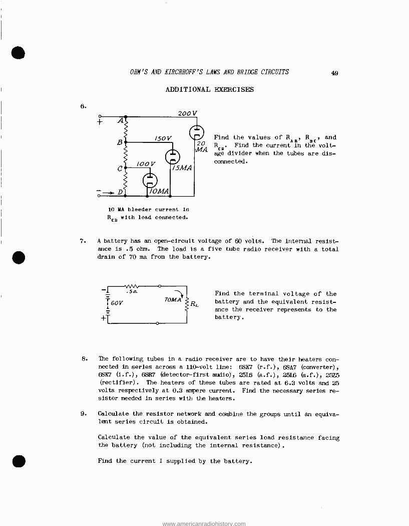
6.
OHM'S AND KIRCHHOFF'S LAWS AND BRIDGE CIRCUITS 49
ADDITIONAL EXERCISES
200V
10 MA bleeder current in
RCD with load connected.
Find the values of RAH, R and BA,
164 RAD. Find the current in the volt-
age divider when the tubes are dis -
connected.
7. A battery has an open -circuit voltage of 60 volts. The internal resist-
ance is .5 ohm. The load is a five tube radio receiver with a total drain of 70 ma from the battery.
Find the terminal voltage of the battery and the equivalent resist- ance the receiver represents to the
battery.
8. The following tubes in a radio receiver are to have their heaters con- nected in series across a 110 -volt line: 6SH7 (r.f.), 6SA7 (converter),
68Ií7 (i.f.), 6SR7 (detector -first audio), 2516 (a.f.), 2816 (a.f.), 25Z5 (rectifier). The heaters of these tubes are rated at 6.3 volts and 25 volts respectively at 0.3 ampere current. Find the necessary series re- sistor needed in series with the heaters.
9. Calculate the resistor network and combine the groups until an equiva- lent series circuit is obtained.
Calculate the value of the equivalent series load resistance facing the battery (not including the internal resistance).
1110 Find the current I supplied by the battery.
www.americanradiohistory.com

50 OHM'S AND IIRCRHOFF'S LAWS AND BRIDGE CIRCUITS
- 2 -
9. Find the voltage across AB and CD.
10.
Find the current I .
a
Find the terminal voltage FL of the battery,
If the circuit shown in the figure is balanced, calculate the current in each resistance and the total current through the battery.
il. Design a voltage divider to provide the following voltages and currents from a 1,500 -volt source. 1,250 volts at 100 ma, 1,000 volts at 60 ma, 600 volts at 30 ma. Specify resistance values that would be used, giving power ratings based on a safety factor of not less than double the dissipation. Assume a bleeder current of 20 ma, and choose nearest whole number for resistor value.
12 Reference problem 11. For the same load requirements redesign the di- vider to also provide negative bias voltages of -50 and -150 volts.
www.americanradiohistory.com

ADDITIONAL EXERCISES 51
- 3 -
13. A 100 -ohm, 200 -watt, continuously variable rheostat will pass how
much current when adjusted to 50 per cent of its total resistance with-
out exceeding the rated power dissipation? Rated power applies to the
entire unit.
14. A 250-volt voltmeter having a resistance of 1,000 ohms /volt is connected
in series with an unknown resistance across a 120 -volt source. If the
voltmeter reads 80 volts, what is the resistance value of the unknown
resistor?
15.
e
/
4
3
G
8 JNN----
Find the total resistance of the circuit. (Hint: Apply delta -wye transformation to either one of two lower meshes, then combine with
other lower mesh, and so on.
ANSWERS TO EXERCISES
1. I -.9123 amp.
IZ = -.3508 amp.
Iloya _ -.5615 amp.
= -.5615 amp. 3. I1
Ia = -.3508 amp. I7,r4 _ -.9123 amp.
2. I . .763 amp. 4. I = .155 amp. I2 . .635 amp.1 Ia
1
= .817 amp.
34 1.398 amp. Iasi = .155 amp.
www.americanradiohistory.com

52 OHM'S AND KIRCHHOFF'S LAWS AND BRIDGE CIRCUITS
ANSWERS TO EXERCISES, Page
5. Iz = .25 amp. I1 = 2.75 I3 = I1 - I9 = 2.5
2.
I10 = 40.8 ma Ie0 = 51.2 ma I8 = 51.2 ma I total mg 92 ma
6. RAB = 1,430 ohms
RBC = 2,500 ohms 11. Ib = 20 ma
RCD = 10,000 ohms R1 = 30,000 ohms, 25 watts I = 14.35 ma R2 = 8,000 ohms, 50 watts
R9 = 2,500 ohms, 75 watts 7. EL = 59.965 volts R* = 1,200 ohms, 150 watts
RL = 856.6 ohms 12. R1 = 500 ohms, 50 watts
8. R = 32.65 ohms R2 = 250 ohms, 25 watts R3 = 30,000 ohms, 25 watts
9. I = 2.74 amp. R4 = 8,000 ohms, 50 watts
VAB = 72 volts Ra = 2,500 ohms, 75 watts
VCD = 36.8 volts R6 = 500 ohms, 50 watts I2 = 1.168 amp. E
t = 99.453 volts 13. 1.41 amp.
10. R = 8 ohms Z
1 115 = 0
Iloo = 40.8 ma
14. 125,000 ohms
15. 1.18 ohms
www.americanradiohistory.com

f
1.
TELEVISION TECHNICAL ASSIGNMENT
OHM'S AND KIRCHHOFF'S LAWS AND BRIDGE CIRCUITS
EXAMINATION
Show all calculations.
It is desired to operate an oscillator tube drawing 80 ma at 800 volts, and an amplifier tube drawing 0.6 ampere at
2,000 volts from a common plate voltage supply source of 2,600 volts. Resistors are used to reduce the voltage from 2,600 volts to that required for each tube. Two circuit arrangements are possible. Sketch a diagram of both, and calculate and show the values of the required resistors. Do
not use a bleeder resistance in these circuits.
Boot o8A
osC.
IF.,, _Zg.S"oolL
I
gpoe4 6A A:),.:. Zboo -Ze- oo_ 400, /000 1 I . o - (o - ,pn+P ..
I/P/000-IL ' .200-8007. l /Be 22,4o0-R
0 8 .08
t.2666 Y
2. Design a voltage distribution circuit for a transmitter to
provide the following voltages and load currents: 1,500 volts at 150 ma, 1,000 volts at 80 ma, 500 volts at 60 ma,
200 volts at 20 ma, and -125 volts at 0 ma. Bleeder cur- rent is to be 10 ma. Sketch the divider, showing the value of each resistor and the total voltage required from the source.
www.americanradiohistory.com

OHN'S AND KIRCHHOFF'S LAWS AND BRIDGE CIRCUITS
EXAMINATION, Page 2.
2.
I
/pl..< <
,Q1 3,000 J L 1 -j 200 vJ
S-6o6 -r / 00 W
/0,060 A,o a/
RßOOtW 3/e M4
40 0 -n-. r/o00 v
OMA
.$'ooJ IpoMA
zpo
rFi
4
es
/./s" 3y/ .3z _..
r~R+ .33. x400
460 _D- 42-64- M
,t o o ,7 0, D O O n- 0/ o, x 2 0/
z -Poo_ : / e o"O-o 1L 03 .óE`x/orob :
-n-- O'r- S ç C9°
09 oy x s10-0 = "...If 141
_ .7y4v r/ 300o
7 8)I+1
3. Given: the circuit shown. Find: the total resistance be- tween tap B and ground ( , taking care to include all paths except the1,000 V generator.
1 ;/1,<, /Q44
,.;K /i3 _ / 0 0 /1 l9
l z60/4/9
R = 100 ohms
R2 = 2 , 000 ohms t 4OMA
R3 = 4,000 ohms
Ra = 1,578 ohms
1/ a.ch.044 R ,. /av X. 3 _ .ao
Rs < ,TDoo x .087 /60 _ V R¢.
/6o . o
/r3 ry000 Y
VR _ 14 +V R3
40o -a/6o --1-.6°
/t 2i,
, g00,
./
<si ; .15..Sóo n- "
¢00 V
l
www.americanradiohistory.com

V- 7/?¢-3..?
WIN'S AND KIRCHHOFF'S LAWS AND BRIDGE CIRCUITS
EXAMINATION, Page 3.
3. y42 _ /- - 2-7o d
t ,{ x C1) -_ /IS- F ñ. : 07, s s â t/s % 8 02 ^ 9,28
,Fra x cñ _6 , 3 S-v o - TrAf,%
, .z.s-Bz 8 x 3s'v-o .2ycr z g
/P3 + ti_ Or an%i C
sóoo 81'z-
86 84
.2 O82 11-_
oo 0
,Z¢ zs'v JL
1L
f-86-0-0xxep-e-v _ 4660 400/400 _,3600rt. /0060
/.lj EJ8 oNN-t--S'
4. In a slide -wire bridge using a 100 -cm slide wire, if, when the circuit is balanced, R1 = 21.2 cm, and R3 = 200 ohms, what is the value of R=?
Rx R3
wvwvv-.-
0 4 20 RANGE OF ACCURATE MEASUREMENT
17,(' /p = Z z C wA / s di s Ta K Ce /9
iPt - ,3 - /ov-.2/.z = 78. c s
á k o( g /F),, /F),, iFX /1 : , Ì1D3
eL
24
f
= zi.S Ap v
7S -8
www.americanradiohistory.com

OHM'S AND KIRCHHOFF'S LAWS AND BRIDGE CIRCUITS
EXAMINATION, Page 4.
5. I
.117. .1511.
I1. f 2V = 3V.-7..
T+ T+
Find the current supplied (or
drawn) by each battery and the current in the load resistor. SHOW THE CURRENTS ASSUMED IN THE DIAGRAM.
6, f z -. + L r. /J - -3
. /S /.)
L l
- m is-1 L = -/ _ . /s t /s
- . ' g 3^ L - - . /
)cS l -- /+ _ LL e z ¢ .4 >II s
-/ ZS-1 _ .3 6 - - 4 .Z./of/' .3 _ .-. -
.zs .s ,Ba- PYy supf P s 2 . z ¢ -+- 2 . 6 s _ e ,.rvoS
.2 ,Qa%fr% c4,raws QV'. s
10 o a d _ ,Z , Z s
www.americanradiohistory.com

OHM'S AND KIRCHHOFF'S LAWS AND BRIDGE CIRCUITS
EXAMINATION, Page 5.
6. Find the value of R1, total circuit resistance, total line current, and battery voltage.
6 )9nNPs 20n. ,Mn,
50n.
65.2
-s-
o-o _ z 4 z 6-0
r?,
/Ò-0 x 4-0 --- T /-s`
V
e,
-3
/oT4/ L = 6 A>.cr J 1 - / 6S /.? 0
,,3O ohm.
-Z04.33.3 +43. 3 i.664145
1 = lo X y6. S2of. Ia7fs
www.americanradiohistory.com

OHM'S AND KIRCHHOFF'S LAWS AND BRIDGE CIRCUITS
EXAMINATION, Page 8.
9. B, then when the lower mesh is connected to C, no current will flow through it. How far in centimeters must C be from B to obtain this condition?
- 24V VV1A/VN
100 Centimeters IO.rL
c 04,-)2
24 dro!° sa
/2 V dYOr
4cr vs,s
--1I1I1I1 + 12V 4
.Z t i
ctxoss / /o
¢ C kg
/ D'D X ¢ /
z 4- GAO
o
www.americanradiohistory.com

OHM'S AND KIRCHHOFFBS LAWS AND BRIDGE CIRCUITS
EXAMINATION, Page 9.
10. Find I in each resistor.
/ A PR, /.5_12 R3
--- /. t s 3
T -- .s = t -. v - .P S
Vacaos s ñ uwa fej î 6 - (3x/) ,3 /
3
-- R. i- 3 _ .Z G ++4
3
www.americanradiohistory.com