specific recommendations for intellipak ii 90 to 150 ton units
TRANSCRIPT

June 2008 RT-PRB022-EN
IntelliPak™ 20-130 Ton and IntelliPak II 90-150 Ton RooftopsSubject: Indoor Sound
Issued by: Clarksville Large Commercial Unitary
Engineering Bulletin
2 © 2008 Trane All rights reserved
Table of Contents
Engineering Bulletin . . . . . . . . . . . . . . . . . . . . . . . . . . . . . . . . . . . . . . . . . . . . . . . . . . . . 3
Introduction . . . . . . . . . . . . . . . . . . . . . . . . . . . . . . . . . . . . . . . . . . . . . . . . . . . . . . . 3
Components of an Acoustical Aspects Model for Rooftop Units . . . . . . . . . . 3Source . . . . . . . . . . . . . . . . . . . . . . . . . . . . . . . . . . . . . . . . . . . . . . . . . . . . . . 3Figure 1. Sources of unit sound. . . . . . . . . . . . . . . . . . . . . . . . . . . . . . . . . . . . 4Receiver . . . . . . . . . . . . . . . . . . . . . . . . . . . . . . . . . . . . . . . . . . . . . . . . . . . . . 4Path . . . . . . . . . . . . . . . . . . . . . . . . . . . . . . . . . . . . . . . . . . . . . . . . . . . . . . . . . 4
Acoustical Analysis, Step-by-Step . . . . . . . . . . . . . . . . . . . . . . . . . . . . . . . . . . . . 5
General recommendations for packaged rooftop units . . . . . . . . . . . . . . . . . . 6Rooftop Unit Location . . . . . . . . . . . . . . . . . . . . . . . . . . . . . . . . . . . . . . . . . . 6Quiet the Source . . . . . . . . . . . . . . . . . . . . . . . . . . . . . . . . . . . . . . . . . . . . . . 6Figure 2. Absorptive insulation lining the interior of the curb. . . . . . . . . . . . . . 7Figure 3. Air flow path-plenum design. . . . . . . . . . . . . . . . . . . . . . . . . . . . . . . 7Supply airborne path . . . . . . . . . . . . . . . . . . . . . . . . . . . . . . . . . . . . . . . . . . 7Supply or return breakout path . . . . . . . . . . . . . . . . . . . . . . . . . . . . . . . . . . 8Figure 4. Gypsum Board Lagging Around Ductwork . . . . . . . . . . . . . . . . . . . . 9Return airborne path . . . . . . . . . . . . . . . . . . . . . . . . . . . . . . . . . . . . . . . . . . . 9Figure 5. Recommended Return Air Side Ducting (Symmetrical Tees) . . . . . . 10Roof transmission path . . . . . . . . . . . . . . . . . . . . . . . . . . . . . . . . . . . . . . . . 11Structure-borne sound . . . . . . . . . . . . . . . . . . . . . . . . . . . . . . . . . . . . . . . . 11
Specific recommendations for IntelliPak II 90 to 150 ton units . . . . . . . . . . . 13
Quiet the Source . . . . . . . . . . . . . . . . . . . . . . . . . . . . . . . . . . . . . . . . . . . . . . . . . . 13Quiet the path . . . . . . . . . . . . . . . . . . . . . . . . . . . . . . . . . . . . . . . . . . . . . . . 15Figure 6. . . . . . . . . . . . . . . . . . . . . . . . . . . . . . . . . . . . . . . . . . . . . . . . . . . . 16Figure 7. . . . . . . . . . . . . . . . . . . . . . . . . . . . . . . . . . . . . . . . . . . . . . . . . . . . 16Figure 8. . . . . . . . . . . . . . . . . . . . . . . . . . . . . . . . . . . . . . . . . . . . . . . . . . . . 17
Guidance from Trane Mock-up Tests . . . . . . . . . . . . . . . . . . . . . . . . . . . . . . . . 17Acoustical Effect of Various Duct Configurations . . . . . . . . . . . . . . . . . . . 17Mock-up Test of 40 Ton Unit over Conference Room . . . . . . . . . . . . . . . 18Figure 9. Duct Breakout Insertion Loss - Potential Low Frequency Improvementover Bare Duct Elbow . . . . . . . . . . . . . . . . . . . . . . . . . . . . . . . . . . . . . . . . . . . 19
Closing Thoughts . . . . . . . . . . . . . . . . . . . . . . . . . . . . . . . . . . . . . . . . . . . . . . . . . 20General recommendations for reducing duct rumble include: . . . . . . . . 21
Suggested Reference Materials . . . . . . . . . . . . . . . . . . . . . . . . . . . . . . . . . . . . . 21
RT-PRB022-EN 3
Engineering Bulletin
Introduction
This Engineering Bulletin describes the basic components of an acoustical model for indoor sound from rooftop units and offers some suggested attenuation techniques. Refer to RT-EB-108 for information on analyzing outdoor sound from IntelliPak™ units. These materials, properly applied, will guide the designer toward producing an optimally quiet air conditioning system installation.
Large packaged rooftop equipment, by the nature of size, components and location, can generate noise. To minimize noise in sound-sensitive areas, acoustical goals should be set as part of the project and should include a acoustical review during the system design process.
One common approach to addressing acoustical concerns is to use a fixed set of design practices on every job. This approach can work well to eliminate sound problems, however, it may unnecessarily inflate the installed cost of some projects, while providing insufficient attenuation on others. This is especially true when the sound data changes due to unit redesign, as in the case of the Trane IntelliPak II rooftop products.
IntelliPak II offers both an extension of the existing size range of IntelliPak units and new features and benefits. Some changes, such as a switch to all solid wall construction for Indoor Air Quality (IAQ) sensitive applications, increase sound levels; others, for instance, several choices of cabinet configurations and fan selections, can lower sound levels.
Note: For additional IntelliPak II application recommendations, see“Specific recommendations for IntelliPak II 90 to 150 ton units,” p. 13.
IntelliPak has been sound rated in accordance with ARI 260 - 2001, "Sound Rating of Ducted Air Moving and Conditioning Equipment". Thus, the acoustical impact of each selectable feature at the specific unit operating conditions can be readily obtained.
Note: Unit sound power level estimates based on theoretical (low flow, point source, etc.) acoustic effects added to fan only sound power levels have been shown to have variances greater than 10 dB in comparison to ARI 260 rating data.
On projects where acoustics is critical, the proper approach is to conduct an acoustical analysis early in the design process. Even a simple acoustical analysis can help achieve occupant satisfaction, while minimizing installed cost.
Components of an acoustical aspects model for rooftop units
A simple acoustical model of a building application consists of three parts: the source, the sound path, and the receiver. Each of these components is described below. The rooftop unit is the source for the acoustical building application model. However, within in the rooftop unit there are multiple internal sound sources and sound paths that combine to affect the application.
Source
The source is where the sound originates. Large, packaged rooftop equipment contains several sound sources, including compressors, condenser fans, supply fans, and relief (exhaust) or return fans. Each source has a unique sound quality and level, but all of them play a role in determining the sound the receiver hears.
The basic sources of sound associated with a rooftop installation are:
1. Supply Fan (See Figure 1)
2. Compressors (See Figure 1)
3. Exhaust/Return Fans (See Figure 1)
4. Condenser Fans (See Figure 1)
5. Flow noise generated at duct fittings. This noise is related to the design of the ductwork—not the rooftop unit.

4 RT-PRB022-EN
Engineering Bulletin
6. Structural vibration generated by compressors and fan assemblies (See Figure 1)
Note: Flow noise can also cause structural vibration if the ductwork is rigidly connected to structural members.
An accurate building application acoustical analysis starts and depends on accurate sound data for the rooftop equipment. Ducted sound power levels, such as "ducted discharge" for the supply duct and "ducted inlet" for the return duct, and indoor sound data for the packaged rooftop equipment should be measured in accordance with ARI Standard 260, Sound Rating of Ducted Air Moving and Conditioning Equipment. This test standard will assure that the ducted sound data for the rooftop accurately reflects the contributions of all the internal unit sound sources, and accounts for the effects of the cabinet, and specific operating conditions.
Note: ARI 260 does not provide sound ratings for the belly pan noise or outdoor product noise that could break through the roof structure.
Receiver
The receiver is simply the location where the sound will be heard and judged against some defined criteria. This could be a private office, a conference room, an open office area, a theater, etc. A building will typically have several receiver locations with varying acoustical requirements.
Path
The path is the route the sound travels from the source to the receiver. Sound from a single source may follow more than one path to the receiver location. For example, sound from the supply fan follows the supply ductwork and enters the occupied space through the supply-air diffuser. Supply fan sound also travels through the walls of the supply duct (breakout), and then through the ceiling into the space.
A Rooftop unit acoustical model typically reviews the following sound paths:
1. Airborne: Sound follows the airflow path. Supply airborne sound travels in the same direction as the supply air. In VAV systems, the supply airborne path is also influenced by the discharge sound from the VAV terminal unit. Return airborne sound travels against the direction of airflow back through the return air path.
2. Breakout: Sound passes through walls of the ductwork, into the ceiling plenum, and then through the ceiling into the occupied space.
Figure 1. Sources of unit sound
1 = Supply Fan(s) A = Return Duct 2 = Compressors B = Supply Duct 3 = Exhaust/Return Fans (Opt.) C = Unit Base 4 = Condenser Fans D = Building Structure

RT-PRB022-EN 5
Engineering Bulletin
3. Roof transmission: Sound passes through the roof deck (either within or outside of the roof curb) into the plenum, and then through the ceiling into the occupied space.
4. Structure-borne: This path differs from the others in that energy is transmitted through the framework of the building. This energy may come directly from the vibration of the sound source, or may be airborne sound that is transferred to the structure.
The sources of sound and the transmission paths are generally similar for all types of HVAC systems whether packaged or built up. Since rooftop equipment is not enclosed by an equipment room, the attenuation offered by walls, ceiling, and floor slabs is not present.
Acoustical analysis, step-by-step
An acoustical analysis consists of five basic steps:
Step 1: Set acoustical goals for the finished space.
It is critical to establish realistic acoustical goals for the occupied space at the outset of any HVAC project. There are always implicit, often subjective, expectations with any project, and it is much easier to satisfy these expectations when they are understood before designing the system. Sound goals will vary depending on how the space is used. Once the sound goals are understood, they can be stated using an appropriate descriptor, such as Noise Criteria (NC) or Room Criteria (RC). Remember the following when defining the desired sound levels:
• As a general rule, lower sound levels cost more to achieve.
• The entire building does not have the same acoustical requirements. Bathrooms and hallways do not need to be as quiet as executive offices and conference rooms. A low-cost, quiet installation takes advantage of this point.
• Successful acoustics requires a team effort, including the owner, design engineer, architect, equipment manufacturer, and installing contractor.
Step 2: Identify each sound path and its elements.
Paths are defined by the end points; the source location and the receiver location. There may be many receiver locations, depending on the installation, but the number can be reduced by determining the critical receiver locations. In general, sound diminishes with distance, so the space directly below the rooftop unit will typically be the loudest. If adjacent spaces have sound targets that are considerably below the level required in the space directly under the unit, these spaces should also be analyzed. Common examples include conference rooms, executive offices, and classrooms. After the critical receiver locations are defined, the sound paths from the source to each receiver can be identified.
Step 3: Perform a path-by-path analysis.
Once each path has been identified, individual elements can be analyzed for their contribution. For example, the supply airborne path includes various duct elements (elbows, straight duct, junctions, diffusers, and so on) and a room-correction factor. Algorithms available from ASHRAE can calculate the acoustical effect of each duct element. The effect of changing an element, such as removing the lining from a section of ductwork, can be calculated. Using a software tool like the Trane Acoustics Program (TAP) makes these algorithms easier to use.
Step 4: Sum the results to determine the acoustical performance of the
installation.
Once the contributions of the individual paths for a particular receiver location are calculated, they must be added together to determine the total sound at the receiver. A unique sum is required for each "critical" receiver location.

6 RT-PRB022-EN
Engineering Bulletin
Step 5: Compare the summations with the acoustical goals in the context of
the project budget.
The sum of the sound paths for a particular receiver location is a prediction of the sound level at that location. If the sum is lower than the sound target for that receiver location, the design does not need to be changed, although it may be reviewed for potential cost reductions. If the estimate exceeds the sound target, the paths are reviewed to determine which paths are dominant. Alterations to the source and/or the path elements are then made to reduce the sound at the receiver location.
This is typically an iterative process, comparing the acoustical effect of various alterations. Once a design meets the acoustical goals for the project, costs should be reviewed to understand the work and costs required to implement the design. Where cost is an issue, system layout alternatives or equipment options should be explored.
General recommendations for packaged rooftop units
It is challenging to put together a list of good, general acoustical practices. Nearly everything on the list results in adding cost to the job; cost that may or may not be justified by the acoustical requirements. For this reason, an acoustical analysis is preferred to meet the acoustical goals at the lowest cost. This section of the bulletin provides useful attenuation ideas that can be employed, as needed, during the acoustical analysis.
Rooftop unit location
The single most effective recommendation to prevent noise problems within a building is to locate the unit over non-critical areas such as copy rooms, restrooms, storage rooms, etc. and other similar non-occupied areas of the building. Never locate a unit directly over or in close proximity to sound sensitive areas such as conference rooms, executive office spaces, libraries, etc.
Quiet the source
Thinking in terms of the Source-Path-Receiver model described above one of the most effective methods of lowering sound at the Receiver location is to generate less sound at the source. Unit options such as a quieter fan or an additional plenum section are examples of quieting the source.
Note: See “Specific recommendations for IntelliPak II 90 to 150 ton units,” p. 13 for sound attenuating options specifically for the IntelliPak II models.
QuietCurb™
The QuietCurb is an acoustically-engineered roof curb product which enhances the Trane IntelliPak by reducing operating sound power levels. In some sizes, the Trane rooftop with the QuietCurb™ accessory may be as much as 18 NC (on the ducted airborne paths) lower than the equivalent size model on a standard roof curb. The patented QuietCurb™ design attenuates all of the sound paths (inlet, discharge, and roof transmission) and lowers structure borne vibration.
Structure borne vibration is reduced through the use of an integral spring-vibration isolation rail.

RT-PRB022-EN 7
Engineering Bulletin
High frequency components of airborne sound on both the inlet and discharge paths are attenuated by the absorptive insulation lining the interior of the curb.
Low frequency sound is reduced through the use of a unique air flow path-plenum design which reduces air turbulence and permits the low frequency noise to "break out" above the roof line before entering the building.
Sound transmitted through the roof of the building is reduced because the compressor and condenser fan sound sources are moved further from the roof deck. If roof density is a concern, refer to section titled 'roof transmission path' for recommendations on concrete slab installations under the compressor section.
Figure 2. Absorptive insulation lining the interior of the curb
Figure 3. Air flow path-plenum design
8 RT-PRB022-EN
Engineering Bulletin
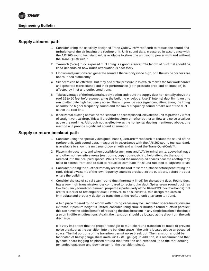
Supply airborne path
1. Consider using the specially-designed Trane QuietCurb™ roof curb to reduce the sound and turbulence of the air leaving the rooftop unit. Unit sound data, measured in accordance with the ARI 260 sound test standard, is available to show the unit sound power with and without the Trane QuietCurb™.
2. Two-inch (5-cm) thick, exposed duct lining is a good silencer. The length of duct that should be lined depends on how much attenuation is necessary.
3. Elbows and junctions can generate sound if the velocity is too high, or if the inside corners are not rounded sufficiently.
4. Silencers can be effective, but they add static pressure loss (which makes the fan work harder and generate more sound) and their performance (both pressure drop and attenuation) is affected by inlet and outlet conditions.
5. Take advantage of the horizontal supply option and route the supply duct horizontally above the roof 15 to 20 feet before penetrating the building envelope. Use 2" internal duct lining on this run to attenuate high frequency noise. This will provide very significant attenuation; the lining absorbs the higher frequency sound and the lower frequency sound breaks out of the duct above the roof line.
6. If horizontal ducting above the roof cannot be accomplished, elevate the unit to provide 7-8 feet of straight vertical drop. This will provide development of smoother air flow and noise breakout above the roof line. Although not as effective as the horizontal ducting mentioned above, this method will provide significant sound attenuation.
Supply or return breakout path
1. Consider using the specially-designed Trane QuietCurb™ roof curb to reduce the sound of the rooftop unit. Unit sound data, measured in accordance with the ARI 260 sound test standard, is available to show the unit sound power with and without the Trane QuietCurb™.
2. Place main duct runs, and when possible branch runs and VAV terminal units, above hallways and other non-sensitive areas (restrooms, copy rooms, etc.) to help attenuate the sound radiated into the occupied spaces. Walls around the unoccupied spaces near the rooftop may need to extend from slab to slab to reduce or eliminate the sound radiated to adjacent areas.
3. Consider running the duct horizontally across the roof for some distance before penetrating the roof. This allows some of the low frequency sound to breakout to the outdoors, before the duct enters the building.
4. Consider the use of spiral seam round duct (internally lined) for the supply duct. Round duct has a very high transmission loss compared to rectangular duct. Spiral seam round duct has low frequency sound containment properties (particularly at the 16 and 32 Hz octave bands) that are far superior to rectangular duct. However, to be successful, this design requires an immediate and properly designed transition at the rooftop unit discharge to round. A two piece mitered round elbow with turning vanes may be used when space limitations are extreme. If plenum height is limited, consider using smaller multiple round ducts in parallel; this can have the added benefit of reducing the duct breakout in any single location if the ducts are run in different directions. Again, the transition should be located at the drop from the unit discharge. It is very important that the proper rectangle-to-multiple round transition be made to prevent noise breakout at the transition into the building space if the unit is located above an occupied space. The flat portions of the transition permit noise break out. The transition should be fabricated of heavy gauge sheet metal (#14 - #16 gauge). In addition, it is recommended that gypsum board lagging be placed around the transition and extended up to the roof decking (extended upstream and downstream of the transition piece).

RT-PRB022-EN 9
Engineering Bulletin
Since the high frequency sound will be contained within the round duct, and transferred down the duct, it is recommended that 2" internal lining be utilized. The lining will help attenuate the high frequency noise.
5. If rectangular duct must be used, realize that this configuration of ductwork has poor properties for resisting the breakout of sound from the ductwork. When using rectangular ductwork the use of heavy gauge sheet metal, #16 - 14 gauge is recommended for the first 20 - 30 feet of duct. Add lagging to the outer surfaces of the ductwork. Lagging is a dense material, such as gypsum board, that increases the transmission loss of the duct wall. The effectiveness of the lagging depends upon 1) the material selected and 2) the method, skill level and experience of the installer.
Three types of lagging should be considered:
a. Gypsum board isolated from the duct. Two layers of 5/ 8" gypsum board are supported on a frame separate from the ductwork. Glass fiber insulation can be added between the duct and the gypsum board, but this insulation must not bridge the gap (this would destroy the vibration isolation from the duct—refer to Figure 4).
b. Use loaded vinyl barrier wraps. A flexible 1/ 8" thick, 1 lb. / sq. ft. loaded, vinyl coated over either acoustic foam or glass fiber blanket can increase the resistance to duct breakout. Reference individual manufacturer's literature for installation details.
c. Gypsum board tight to duct. Two layers of 5/ 8" gypsum board over a 1" glass fiber blanket screwed tight to the duct provides an acoustic barrier and some vibration damping. No attempt is made to keep the gypsum board isolated from the duct vibration.
6. Use a gypsum board ceiling rather than acoustical tile. This increases the transmission loss of the ceiling, but it will also have a negative effect by decreasing the absorption of sound within the occupied space.
Return airborne path
1. Consider using the specially-designed Trane QuietCurb™ roof curb to reduce the sound and turbulence of the return air. Unit sound data, measured in accordance with the ARI 260 sound
Figure 4. Gypsum board lagging around ductwork

10 RT-PRB022-EN
Engineering Bulletin
test standard, is available to show the unit sound power with and without the Trane QuietCurb™.
2. On ducted returns use internally lined duct (2" minimum thickness is recommended). Exposed lining lowers duct borne sound with less pressure drop than a silencer. The length of ductwork to be lined depends on the sound target for the occupied space; however, 20ft is a general rule of thumb.
3. Size all return air ducts for 900 - 1000 feet per minute maximum air velocities. Elbows and junctions can generate sound if the velocity is too high, or if the inside corners are not rounded sufficiently.
4. For open plenum return systems, a heavy gauge internally lined boot or "T" section should be used (refer to Figure 5).
5. To take advantage of duct end reflection losses, the return duct should terminate in the ceiling plenum, without an obstruction on the end (no diffusers or grilles), and must have four equivalent duct diameters of unobstructed straight duct. Duct end reflection loss increases as the duct size decreases so splitting the return duct into multiple, smaller ducts increases the attenuation. Each "leg" of the return ductwork should be 3 to 5 duct diameters long. Add a "T" on to a "T" if necessary to get a small enough final inlet cross section to achieve the end reflection loss (refer to Figure 5). More low frequency attenuation can be achieved through end reflection loss than by adding duct silencers. In addition to increased duct end reflection loss splitting the duct into a T or even H configuration also provides attenuation at the T-junction(s), by attenuation due to the additional length of lined ductwork, and from increasing the distance between return duct openings.
6. Silencers can be effective, but they add static pressure loss (which makes the fan work harder and generate more sound) and their performance (both pressure drop and attenuation) is affected by inlet and outlet conditions."
Figure 5. Recommended return air side ducting (symmetrical tees)

RT-PRB022-EN 11
Engineering Bulletin
Roof transmission path
1. The primary way to reduce roof transmitted sound is to locate the rooftop unit over an area that is not sound sensitive. (If the unit is located directly above a sound sensitive area, additional sound reduction measures will be required.
2. Consider using a QuietCurb™ roof curb to reduce the sound transmission and raise the compressors and condenser fan slightly farther away from the surface of the roof. It may also help to raise the rooftop unit up on supports to lift it further above the roof surface.
3. The density of the roof may need to be increased. Lightweight, built-up roofs provide very little sound attenuation. It may be necessary to pour a concrete slab in the area under and around the rooftop unit. As general rule-of-thumb, the slab should extend out past the edges of the unit by 1.5 times the height of the unit.
4. It is difficult to predict the sound contribution coming from the base pan of the unit because the strength of the sound source is not measured as part of any rating standard. A conservative approach would be to treat the portion of the roof under the curb in the same manner as the roof surrounding the unit. For example, if a concrete slab surrounds the unit, concrete should also be used inside the curb.
5. Minimize the amount of roof that is cut away inside the curb and fill the remaining gaps with acoustical mastic. It is very important to carefully seal the openings around the ducts. A leakage area of approximately 1% results in a 40% reduction in the effectiveness of the acoustical barrier.
6. Additional mass can be added inside the curb to provide even greater attenuation. Fill the curb with several layers of gypsum board, stagger and seal the joints between pieces, and seal the joints around the duct and between the duct and the curb.
7. Trane's pedestal mounted rooftop unit design transmits less sound through the roof. Compressor sound is allowed to break out above the roof line (there is no direct path to the occupied space as with full perimeter curb support systems). Also, because the base pan is not present in the condensing section, the potential for radiating sound from the base pan (which can resonate like a drumhead) is eliminated.
Structure-borne sound
This path is unique because the source of the sound is structure-borne vibration. The fans and compressors inside the rooftop unit generate vibrations that are transmitted to the frame of the unit. This energy can be transmitted to the structure of the building, where it follows various paths, and is then re-radiated into the occupied space as audible sound. As with airborne paths, it is possible to predict what is required to prevent structure borne vibration from being a problem. However, structure-borne vibration paths are often difficult to identify, and the calculations are fairly complex. Since structure-borne vibration is less likely to be a problem than airborne sound, it is common to follow a few general best practices rather than do a complex analysis.
Some packaged rooftop equipment arrives with the vibrating components internally isolated. In many cases, this may be enough isolation to prevent structure-borne vibration problems. The amount of isolation required is largely dependent on the building structure supporting the unit. Some general guidelines on vibration isolation are provided in ASHRAE publication, A Practical Guide to Noise and Vibration Control for HVAC Systems:
"The roof structure should be stiff enough to deflect no more than ¼ inch (0.6 cm) under the combination of the dead load and the operating load of the unit. This may require 20-foot (6-m) column spacing in the vicinity of the unit."
For equipment larger than 20 tons (70 kW) of cooling capacity, this guide goes on to recommend:
"For installations over noise sensitive areas, mount the unit on high deflection spring isolators resting on grillage that is supported 2 to 3 feet (0.6 to 0.9 m) above the roof line by extensions of the building columns."

12 RT-PRB022-EN
Engineering Bulletin
Important: Although rare, the use of both internal and external vibration isolation can cause the system to experience a resonance condition.
Finally, an ASHRAE paper, titled "Sound and Vibration Considerations in Rooftop Installations," suggests the following static deflections for the springs:
"A rooftop unit, mounted on a good stiff roof, can use an isolation system with 1- or 2-inch (2.5- to 5 cm) static deflection on the springs. But a unit on a flimsy roof may require 3 to 5 inches (7.5 to 12.5 cm) of static deflection to achieve adequate vibration isolation because of the lower natural frequency of the flimsy roof."
Proper installation of the springs is just as important as properly specifying them. Spring effectiveness can be virtually eliminated by any of the following:
a. Attaching an electrical conduit (or pipe) to the rooftop unit and then to the roof (or curb), without flexible connectors.
b. Placing any material (roofing tar, scraps of wood, etc.) between the bottom of the unit and the top of the curb.
c. Applying horizontal pressure to the unit (misalignment) that causes the spring guides to make contact.
d. Attaching ductwork to the unit without flexible connectors.
Proper vibration isolation to eliminate vibration transmission is only possible if the building structure is sufficiently rigid to serve as a base for the mechanical equipment. To help isolate the unit from the building consider the following:
1. Use an inertia base or solid concrete pad as a base for the rooftop unit. This mass properly supported will provide vibration dampening and prevent low frequency noise from breaking out through the roof directly below the unit.
2. Isolate the unit on spring isolation rails selected to match the characteristics of the roof structure.
Important: Do not allow large rooftop equipment to be applied to buildings with a lightweight roof structure unless column supports are provided which are independent of the roof structure. Otherwise, the entire lightweight roof structure in the vicinity of the unit will vibrate, transmitting this vibratory motion throughout the entire building structure!
3. Always use an approved, fire-resistant flexible canvas connector when making duct connections to the rooftop unit or curb to prevent transmission of vibration through the duct system. After penetrating the building envelope, and especially when dropping the duct through a vertical chase, do not allow the duct to be in direct contact with chase walls or rigidly attached to structural members of the building. Vibration may be transmitted through the duct system and into the building structure.
4. Do not support ductwork rigidly to building structural members or chase walls. Use hanger isolators and do not allow ductwork to be mounted in direct contact with the walls.
5. Locate the unit over unoccupied areas of the building such as a storage room, restroom, etc., over vertical supports. Do not locate the unit in the middle of a horizontal beam avoid large column spans! This will minimize the roof deflection and minimize vibratory transmission.
In addition, the reader is also encouraged to read the ASHRAE paper NY-91-3-3, also, an article from the ASHRAE Journal, May 2000, "Practical Guide - Controlling Noise From Large Rooftop Units" by Dave Guckelberger, and the other reference materials listed at the end of this publication. NY-91-3-3, "Sound and Vibrations in Rooftop Installations" (written by R.G. Harold, P.E. with the Trane Acoustics Laboratory), deals with the fact that proper sound control is a result of controlling the system (e.g., building structure, air distribution system and the rooftop equipment). Reprints of this paper are available from Trane upon request.
RT-PRB022-EN 13
Engineering Bulletin
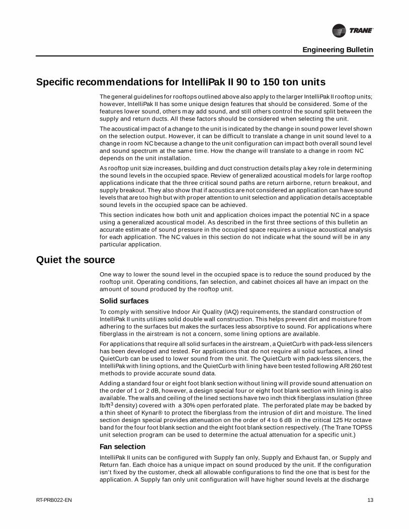
Specific recommendations for IntelliPak II 90 to 150 ton units
The general guidelines for rooftops outlined above also apply to the larger IntelliPak II rooftop units; however, IntelliPak II has some unique design features that should be considered. Some of the features lower sound, others may add sound, and still others control the sound split between the supply and return ducts. All these factors should be considered when selecting the unit.
The acoustical impact of a change to the unit is indicated by the change in sound power level shown on the selection output. However, it can be difficult to translate a change in unit sound level to a change in room NC because a change to the unit configuration can impact both overall sound level and sound spectrum at the same time. How the change will translate to a change in room NC depends on the unit installation.
As rooftop unit size increases, building and duct construction details play a key role in determining the sound levels in the occupied space. Review of generalized acoustical models for large rooftop applications indicate that the three critical sound paths are return airborne, return breakout, and supply breakout. They also show that if acoustics are not considered an application can have sound levels that are too high but with proper attention to unit selection and application details acceptable sound levels in the occupied space can be achieved.
This section indicates how both unit and application choices impact the potential NC in a space using a generalized acoustical model. As described in the first three sections of this bulletin an accurate estimate of sound pressure in the occupied space requires a unique acoustical analysis for each application. The NC values in this section do not indicate what the sound will be in any particular application.
Quiet the source
One way to lower the sound level in the occupied space is to reduce the sound produced by the rooftop unit. Operating conditions, fan selection, and cabinet choices all have an impact on the amount of sound produced by the rooftop unit.
Solid surfaces
To comply with sensitive Indoor Air Quality (IAQ) requirements, the standard construction of IntelliPak II units utilizes solid double wall construction. This helps prevent dirt and moisture from adhering to the surfaces but makes the surfaces less absorptive to sound. For applications where fiberglass in the airstream is not a concern, some lining options are available.
For applications that require all solid surfaces in the airstream, a QuietCurb with pack-less silencers has been developed and tested. For applications that do not require all solid surfaces, a lined QuietCurb can be used to lower sound from the unit. The QuietCurb with pack-less silencers, the IntelliPak with lining options, and the QuietCurb with lining have been tested following ARI 260 test methods to provide accurate sound data.
Adding a standard four or eight foot blank section without lining will provide sound attenuation on the order of 1 or 2 dB, however, a design special four or eight foot blank section with lining is also available. The walls and ceiling of the lined sections have two inch thick fiberglass insulation (three lb/ft3 density) covered with a 30% open perforated plate. The perforated plate may be backed by a thin sheet of Kynar® to protect the fiberglass from the intrusion of dirt and moisture. The lined section design special provides attenuation on the order of 4 to 6 dB in the critical 125 Hz octave band for the four foot blank section and the eight foot blank section respectively. (The Trane TOPSS unit selection program can be used to determine the actual attenuation for a specific unit.)
Fan selection
IntelliPak II units can be configured with Supply fan only, Supply and Exhaust fan, or Supply and Return fan. Each choice has a unique impact on sound produced by the unit. If the configuration isn't fixed by the customer, check all allowable configurations to find the one that is best for the application. A Supply fan only unit configuration will have higher sound levels at the discharge

14 RT-PRB022-EN
Engineering Bulletin
opening than the return. Using an Exhaust or Return fan creates higher sound levels at the return opening but may lower the sound level at the discharge.
The generalized acoustical model indicates that both the discharge and inlet path must be considered to obtain the best acoustical performance. A supply fan only configuration tends to perform well because of the plenum attenuation created by the heat and coil sections on the supply, and mixing and return sections on the return. Switching to a supply and exhaust fan configuration increase the sound in the occupied area below the rooftop by 3 NC. Switching to a supply and return fan may result in an 11 NC increase over the supply fan only unit.
Also check all available size choices for a given unit. In general, moving to a larger fan will lower the sound level for a given flow and pressure drop. However, moving to a larger fan may also move the fan closer to a region where "acoustical stall" occurs.
Acoustic stall
Fans enter a region of acoustical stall prior to entering aerodynamic stall. When operating in an acoustical stall region the fan will reliably move air, however, the low frequency sound produced by the fan will be inconsistent and highly variable, thus making it impossible to provide accurate representative acoustical data. In addition, when the fan is operating in this region even small changes to the fan operating condition can produce unpredictable changes in the low frequency sound level.
Unit selections are allowed in the acoustical stall region but the selection program will not provide acoustical data. Fans should not be selected in the acoustical stall region when acoustics is important application consideration. It should also be noted that a fan selected above the acoustical stall region could unload into the stall region; check the selection at part load conditions to avoid this problem.
Supply fan
The dominant sound source in rooftop units is the supply fan. Low frequency sound generated by the fan is easily transmitted to the conditioned space both through the duct walls (duct breakout) and down the ductwork (supply airborne).
To help attenuate the supply fan discharge sound, consider using the "Standard cfm", or the largest supply fan available in each tonnage size. Larger fans run at a lower speed and are typically quieter for example, by 10 dB in the 250 and 500 Hz octave bands at 32,000 cfm and 5" of fan static. In the 90-105T units a 40" DW AF fan is available as a Design Special.
Unit sound data is dependent both on fan type and operating point. It is best to check all available fan selections for a particular operating point. The cost implication of changing the fan type should also be considered. It may be more cost effective to quiet the unit/installation by another method.
Return/Exhaust fan sound
Adding a return or exhaust fan will change the discharge sound from the supply fan. The change in supply sound depends both on the type and operating point of the return/exhaust fan used. However, the greatest impact from adding a return or exhaust fan will be in the sound transmitted through the return air opening. Sound radiated from the return opening comes from the inlet of the supply fan plus the exhaust or return fan (depending on what fans are supplied with the unit). Adding a return fan may cause the return airborne and breakout sound paths to set the sound levels in the occupied space.
In general return fans result in higher sound levels in a space than exhaust fans because the inlet to the return fan is mounted directly above the return ductwork. Exhaust fans are mounted on a side wall of the return plenum section which allows for some attenuation of the exhaust fan sound by the plenum. Also, different fan types and operating points are used for the two fans so the sound created will be unique to each fan at each operating point.
To lower the sound being transmitted through the return air opening, consider the following:

RT-PRB022-EN 15
Engineering Bulletin
1. Review the sound data for Return vs. Exhaust fan for your conditions to determine which configuration results in the lowest sound levels. Also look at all fan options for each configuration. There are two matching sets of supply and return fans for each tonnage size of the IntelliPak II. Changing the supply and return fan size results in blade pass at a different frequency so some octave bands may increase and some decrease, but moving to a larger fan can have a significant effect. For example, switching to the larger return fan at 27,000 cfm and 2" of fan static will reduce the 250 and 500 Hz bands by 4 and 5 dB respectively.
2. Consider using a horizontal connection (if available for the configuration) for the unit return and running the return duct over the roof before penetrating the building. Although return sound from the unit is slightly higher for a horizontal return configuration running the return duct over the roof has several advantages:
• Low frequency sound will break out of the duct walls reducing the sound entering the building
• Lining the duct run on the roof will provide attenuation at the mid and upper frequencies
• The duct penetration can be moved to a non-sound sensitive area of the building.
Quiet the path
Changing the installation can have a dramatic effect on sound levels in the occupied space. Rooftop units, because they contain a variety of sound sources (condenser fans, compressors, supply and return or exhaust fans) in close proximity, represent a concentrated sound source. Increased unit sizes result in increased sound levels. In addition to configuring the unit to be as quiet as possible it is also necessary to look at how it is integrated with the building.
Location
Locating a large rooftop unit over a sound sensitive area will either result in unacceptably high sound levels in the occupied area or add considerable cost to prevent the sound produced by the unit from reaching the occupants. Consider locating the unit over a non-sound sensitive area even if it means running the supply and return ducts over the roof. The added expense of the external duct runs will likely be less than the expense of quieting a unit placed over occupied space. In addition, the external runs of duct can provide attenuation of the supply and return airborne sound before the roof penetration is made.
Roof structure
Sound radiated from the compressors, condenser fans, exhaust fans, and the casing of the unit will impinge on the roof surface surrounding the unit. A lightweight roof (metal deck with insulation and ballast) provides minimal resistance to the transmission of sound. The transmission loss of the roof can be increased by adding mass to the roof, typically a concrete slab, around the unit. Thickness and area of the slab are dependent on how much transmission loss is required to meet the sound goals for the job.
Also, as described in the structural consideration section, a flexible roof structure can easily transform vibration from the unit into sound that radiates into the building. As with all rooftop units, placing the unit in a location over a column or other stiffening element will minimize this problem. Proper support is especially important for larger units because of the increased mass and vibration energy due to larger compressors and fans, and high airflow.
Duct chase
Often a large rooftop unit will serve several floors of a building with supply and return ducts running in duct chase between the floors. Properly positioning the unit over the chase can have a dramatic effect on the sound levels in the occupied areas near the unit.

16 RT-PRB022-EN
Engineering Bulletin
Figure 6 shows a construction that will provide a high level of path attenuation. Using a QuietCurb not only provides unit attenuation but it brings the supply and return openings closer so they can be matched up with the chase opening. Notice that a short run (height of one floor) of return duct is installed inside the chase; this provides some additional return breakout transmission loss which lowers the sound levels in the chase. Return air openings at the floors are supplied with a silencer and a short run of lined return duct to provide additional attenuation and move the return airborne sound away from the shaft wall. Round duct is used for the supply to reduce duct breakout near the chase wall.
Removing the short run of return duct from the configuration shown in Figure 6 may result in an increase of 10 NC for the supply fan only unit and 12 NC for the supply and exhaust fan unit. Removing the QuietCurb and adding an 8ft lined plenum section to the supply end of the unit may cause an increase of 5 NC for both the supply fan only and the supply and exhaust fan configurations assuming that both the supply and return are still located directly over the shaft.
Figure 6.
Figure 7.
Supply Fan
Not to scale
Quiet Curb
Round supply duct Return silencer and return duct
Ceiling tileCeiling tile
Exhaust FanSupply Fan
Not to scale
Ceiling tile Ceiling tile

RT-PRB022-EN 17
Engineering Bulletin
Locating either the supply or return opening over the chase and then ducting the other opening to the chase is not recommended (see Figure 7 and Figure 8). An exception to this guidance is provided for jobs where a poured concrete roof curb is used. Poured concrete roof curbs are typically used in conjunction with a concrete roof slab to minimize roof transmission. With the concrete curb the supply opening should be located over the shaft, as in Figure 7, with the return duct run inside the concrete curb to the shaft.
In all chase applications it is important that the chase is run all the way to the roof deck and is sealed with acoustical mastic to the roof deck. Supply and return air duct penetrations though the shaft wall must also be sealed to prevent sound from leaking out of the shaft.
Guidance from Trane mock-up tests
Acoustical effect of various duct configurations
Trane conducted an extensive acoustical test program to investigate the treatment needed to minimize sound transmission from supply ductwork. The initial testing was conducted on a variety of duct configurations. The sound reduction of each duct configuration was measured in reference to a plain rectangular duct with a 90-degree turn below the rooftop.
Duct configuration tests were conducted in Trane's Acoustic Laboratory using ANSI qualified reverberant rooms. All tests were run utilizing a 40-ton rooftop fan assembly at 20,000 cfm of airflow at 2" T.S.P. The 40-ton fan assembly consisted of two parallel, forward-curved, 20" diameter fan wheels.
The different combinations and the resulting sound reduction in the critical first three octave bands are shown in Figure 9, p. 19. Sketches of each duct configuration are included in the table following the test comparisons. The table can be useful in matching the degree of alteration required to the amount of attenuation required for the job.
Table 11 focuses on the first three octaves because these are typically the critical bands for duct breakout on rooftop units utilizing forward curved fans. While duct breakout is typically a low frequency problem units with a different fan type may shift the critical bands. The test configuration also assumed that the supply duct would be directly over occupied space. At some point, as the acoustical sensitivity of the occupied space and unit size increase, it becomes inappropriate to place a rooftop unit directly over occupied space without the guidance of an acoustical consultant.
Figure 8.
Exhaust FanSupply Fan
Not to scale
Ceiling tileCeiling tile

18 RT-PRB022-EN
Engineering Bulletin
Mock-up test of 40 ton unit over conference room
A second series of tests were conducted at the Trane sound facilities utilizing a "real world" conference room mock-up. These tests were run utilizing a 40-ton rooftop unit on top of a room sized and finished to represent a conference room. Based upon the conference room mock-up sound tests conducted by Trane, the following methods may be utilized to reduce or eliminate the supply ductwork noise component of the air distribution system:
1. First and foremost—do not locate the supply discharge trunk line ductwork directly above sound sensitive areas! Mock-up experience indicated that it is not cost effective to achieve conference room sound levels with a 40 ton unit located directly over the conference room.
2. Utilizing 20 gauge duct, routed 14 feet horizontally off the downflow discharge (before penetrating the roof), an NC 40 indoor sound level was achieved. Use of a 2" internal lining is recommended to attenuate the higher frequency noise components. Based upon mock up results, EXTERNAL HORIZONTAL DUCTING WITH LINING WILL PROVIDE A SIGNIFICANT REDUCTION IN THE INDOOR SOUND LEVEL.
3. If horizontal ducting cannot be applied, utilize a roof curb of greater height than a standard curb. When elevating the rooftop unit, a minimum of 7 - 8 feet of straight vertical drop should be provided to allow smooth, laminar air flow to develop more completely. Also, the elevation allows the higher velocity, turbulent airflow noise from off the fan discharge to break out / dissipate before reaching occupied spaces. Although not as effective as ducting horizontally above the roof, this method of routing supply duct will provide significant attenuation.
4. When rectangular duct is used and routed within the building envelope, the fact is that this configuration of duct is very poor at resisting the break out of low frequency noise. Hence, for the routing of the first 20 -30 feet of rectangular duct, within the interior of a building, use heavy gauge (#16- #14) sheet metal to minimize noise break out. Gypsum board lagging is also recommended to provide additional protection against low frequency noise break out.

RT-PRB022-EN 19
Engineering Bulletin
Reprinted by permission of ASHRAE from the 2007 HVAC Applications Handbook, chapter 47, page 47.7
Figure 9. Duct Breakout Insertion Loss - Potential Low Frequency Improvement over Bare Duct Elbow
Discharge Duct Configuration 12 ft of Horizontal Supply Duct Side view End view
Rectangular duct; no turning vanes 0.0 0.0 0.0 (Reference)
Rectangular duct: one dimensional 0.0 0.5 0.5 Turning vanes.
Rectangular duct: two dimensional 0.0 0.5 1.0 Turning vanes.
Rectangular duct: wrapped with foam 4.0 3.0 4.5 And lead.
Rectangular duct; wrapped with glass 4.0 7.0 5.5 fiber, one layer of 5/8 in. gypsum board.
Rectangular duct; wrapped with glass fiber, two layers of 5/8 in. gypsum board 7.5 8.5 9.0
Rectangular plenum drop; three parallel 1.0 2.0 3.5 rectangular supply ducts.
Rectangular plenum drop; one round 8.0 9.5 6.0 supply duct.
Rectangular plenum drop: three parallel 10.5 13.5 8.0 round supply ducts.
Rectangular to multiple drop: round 17.5 11.5 13.0 mitered with turning vanes, three parallel round supply ducts.
Rectangular to multiple drop: round 18.0 13.0 16.0 mitered elbows with turning vanes, three parallel round lined double wall, 22 in. OD supply ducts.
Round drop: radius elbow, single, 15.0 16.5 9.5 37 in. diameter supply.
63 125 250

20 RT-PRB022-EN
Engineering Bulletin
Closing thoughts
Operate the unit as designed
It is quite common to overestimate system static pressure requirements to achieve design airflow. This results in the installation of larger motors and/or higher rpm drives than required to overcome the actual static pressure. To compensate for the additional static the air terminal device balancing dampers are more restricted than necessary. These "over-aired" systems waste energy and the force the units to generate excess sound.
For minimum noise, operate the rooftop at the lowest possible pressure in the duct. After installing the rooftop unit, and its associated air distribution system, it must be properly air balanced by qualified air balancing technicians using calibrated air measuring devices. The airside system should be balanced to achieve the desired airflow at all terminal outlets while maintaining the lowest possible fan rpm and system static pressure.
Sound masking systems
Background sound can be useful in many environments to reduce disturbance. For example, in an office environment background sound can mask nearby conversations preventing them from being noticeable. Effective sound masking requires not only the proper level of background sound but also a well balanced sound spectrum.
Often the HVAC system is useful in generating an appropriate background sound level, however, it may not provide a well balanced spectrum. Low frequency sound is much more difficult to attenuate than high frequency sound; as a result the attenuation of HVAC sound can result in a sound spectrum that is dominated by low frequency sound. The resulting overall sound level in the occupied area may be acceptable but the imbalance makes the spectrum annoying.
Sound masking systems can be used to add the proper amount and type of additional sound to fill out the spectrum. The added sound fills in the missing portion of the noise and makes the combined sound spectrum more pleasing.
Proper duct design
The fans in the rooftop unit are not the only sound source in the HVAC system. Aerodynamic noise is generated at duct fittings such as elbows, diffusers, dampers, and take-offs. The sound power levels generated at these fittings are dependent on airflow turbulence, fitting geometry, and airflow velocity. Meeting the acoustical goals for the job requires all sources of sound need to be considered.
Several guidelines for minimizing the generation of aerodynamic noise are available. The ASHRAE book, "A Practical Guide to Noise and Vibration Control for HVAC Systems" is a good reference source for designing quiet HVAC systems as are the ASHRAE Handbooks.
Careful duct design is especially important at the discharge of the rooftop unit. Air leaving rooftop units tends to be turbulent; improper duct design will generate rumble. The ASHRAE System Guide's discussion of this subject is presented below.
Rumble results when excessive low frequency sound energy is generated in an air distribution system; most frequent cause is poor (turbulent) air flow conditions at the fan discharge or in the immediate downstream duct section. The troublesome frequency region is usually below 250 Hz, extending frequently down through 31.5 and 16 Hz octave bands. Once generated, sound energy in these low frequencies is not easily attenuated; it is transmitted readily both downstream and through the duct walls. Most add-on devices such as silencers or lagging are inefficient in low frequencies. Rectangular ductwork, because of flexibility, is more likely to cause trouble than circular ductwork. Good airflow design at or near the fan is the most effective method of avoiding possible rumble conditions.

RT-PRB022-EN 21
Engineering Bulletin
General recommendations for reducing duct rumble include:
1. Size rectangular ductwork for low velocities. Round duct can be sized for medium velocity airflow.
2. Allow smooth airflow to develop between fittings by allowing at least three duct diameters between any duct fittings.
3. Avoid abrupt changes in duct direction.
4. Choose the most efficient fittings— the greater the pressure drop, the greater the sound power generated.
5. Keep duct runs straight between fittings.
Procedures for estimating sound power as generated by various fittings are represented in the ASHRAE Handbook "HVAC Applications". In addition to the information presented above, Trane offers a variety of additional aids for guidance in designing a "sound system". Available from the Customer Direct Service (C.D.S.) Network of Trane is the Trane Acoustics Program (T.A.P.). This state-of-the-art program aids the mechanical designer in producing a quiet job. Also available is the Trane "Acoustics in Air Conditioning" applications engineering manual (literature order number ISS-APM001-EN).
Suggested reference materials
1. ASHRAE. 1991. Schaffer, Mark E. "A Practical Guide to Noise and Vibration Control for HVAC Systems". Atlanta, GA: American Society of Air-Conditioning Engineers, Inc. (Revised every four years)
2. ASHRAE. 2007. "ASHRAE Handbook-2007 HVAC Applications", chapter 47. Atlanta, GA: American Society of Air-Conditioning Engineers, Inc.
3. ASHRAE. 2005. "ASHRAE Handbook-2005 Fundamentals", chapter 7. Atlanta, GA: American Society of Air-Conditioning Engineers, Inc.
4. ASHRAE. Paper NY 91-3-3 or ASHRAE Transactions, 1991, Vol. 97, Part 1, "Sound and Vibration Considerations in Rooftop Installations", R.G. Harold, P.E. (Copies available from Trane Commercial Unitary Systems Product, Planning and Support Group, Clarksville, TN).
5. Harris, Cyril M. 1979. "Handbook of Noise Control", New York, NY: McGraw-Hill Book Co.
6. Jones, Robert S. 1984. "Noise and Vibration Control in Buildings", New York, NY: McGraw Hill Book Company
7. Trane 2006 "Acoustics in Air Conditioning". Application Manual ISS-IPM001-EN. La Crosse, WI

www.trane.com
For more information, contact your local Trane office or e-mail us at [email protected]
Literature Order Number RT-PRB022-EN
Date June 08
Supersedes RT-EB-80
Trane has a policy of continuous product and product data improvement and reserves the right to change design and specifications without notice.