specification data cm36005 09/10
TRANSCRIPT

Specification DataCM36005
09/10
36005 Series V-Max®
High Capacity V-Ported Control Ball Valve
Putting You In Control

2 | Dresser Masoneilan2 | Dresser Masoneilan
DresserMasoneilan36005SeriesV-Max®
HighCapacityV-PortedControlBallValve

CM36005 - 36005 Series V-Max® High Capacity V-Ported Control Ball Valve | 3
The V-Max® is a high capacity, heavy duty automatic throttling control ball valve incorporating the following features:
• Integrally cast ASME 150 or 300 class raised face flanges. Eliminates long tie rods and simplifies alignment.
• Installation flexibility – Two face to face dimensions are available. Standard construction is in accordance with ISA S75.04 and IEC 534-3-2. Also avail-able in ANSI B16.10 short pattern face to face dimensions (ANSI class 150 only).
• Straight through flow pattern provides exceptional capacities.
• Patented dual-characterized V-port ball combines an equal percentage flow characteristic with high capacities and greater than 500:1 rangeability.
• Standard EF Seal (Emission Free) packing system provides long term, zero leakage† shaft sealing performance.
• MN-7 low-friction polymeric seal ring provides reliable Class VI shutoff.
• 316 Stainless Steel seal ring for Class IV shutoff and higher temperature capability when combined with satellite bearings and flexible graphite packing. Unique seal design requires no shims.
• Optional (NPS 1-6) Heavy Duty Seat provides longer service life in harsher applications. The wiping action of the seal ring against the ball prevents build up of contaminants maintaining long-term performance and reliable Class IV shutoff.
• Full involute spline connections on plug, shaft and actuator connections virtually eliminate backlash, providing reliable operation and ease of main-tenance.
• Easy maintenance – The seal ring may be changed by simply removing two machine screws on the inlet flange. Actuator removal or complete valve disassembly is not required.
Foreword
Table of Contents Foreword ............................................................................................................3
Numbering System ........................................................................................4
Actuator Mounting Guide ...............................................................................5
General Data ..................................................................................................7
Temperature/Seat Leakage .............................................................................9
Cv and FL versus Travel.................................................................................10
Materials of Construction .....................................................................................11
Dimensions ..................................................................................................15
Weights ........................................................................................................19
† Factory Mutual certified report

4 | Dresser Masoneilan
31 Spring opposed, rolling diaphragm. Air to close, fail open action.
32 Spring opposed, rolling diaphragm, Air to open, fail closed action.
33 Spring Diaphragm. Air to extend action
only.
Actuator Type Body Series
36
Actuator Mounting
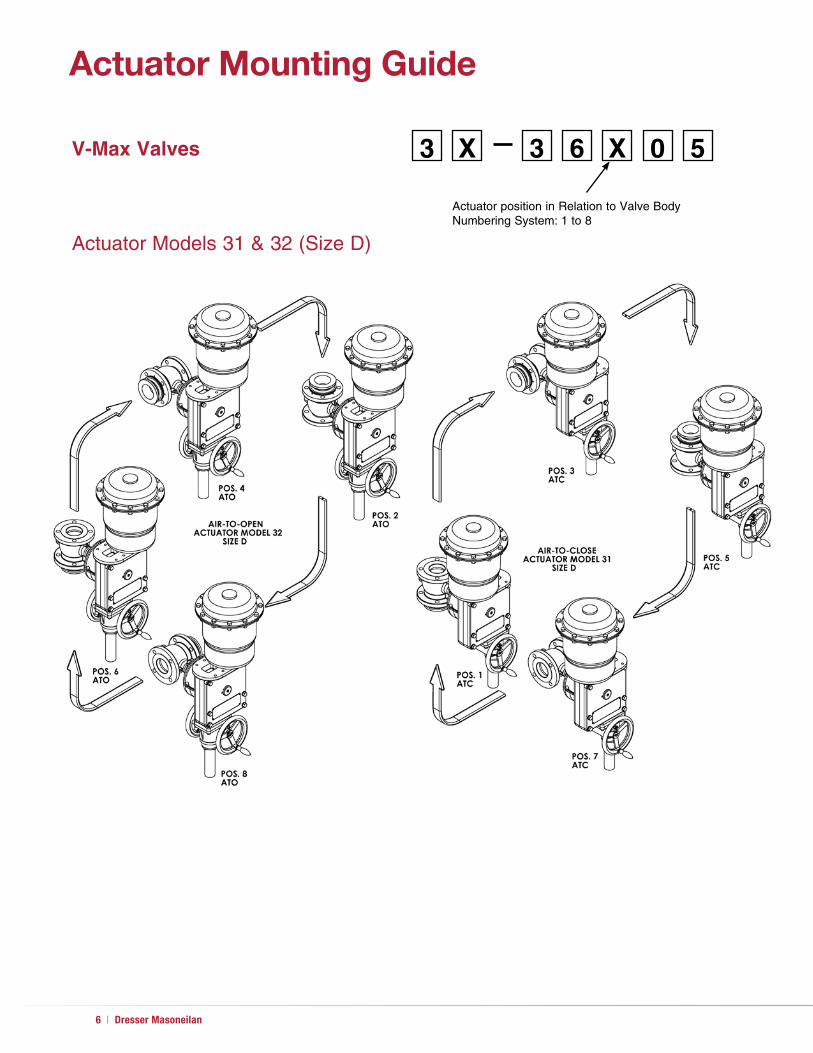
0 Undefined
1 Parallel to pipeline. Valve closes on stem extension (Air to Close, Fail Open).
2 Parallel to pipeline. Valve opens on stem extension (Air to Open, Fail Closed).
3 Vertical above center. Valve closes on stem extension (Air to Close, Fail Open).
4 Vertical above center. Valve opens on stem extension (Air to Open, Fail Closed).
5 Parallel to pipeline. Valve closes on stem extension (Air to Close, Fail Open).
6 Parallel to pipeline, valve opens on stem extension (Air to Open, Fail Closed).
7 Vertical below center. Valve closes on stem extension (Air to Close, Fail Open).
8 Vertical below center. Valve opens on stem extension (Air to Open, Fail Closed).
Seal Type
1 MN-7 Seal Ring
2 316 SS Seal Ring
3 Heavy Duty Metal Seal Ring (Optional)
5
Design Series
Note:
Actuator sizes B and C are only supplied in positions 3, 4, 7 or 8.
Numbering System
2nd 3rd 4th 5th2nd
6
1st
3
1st

CM36005 - 36005 Series V-Max® High Capacity V-Ported Control Ball Valve | 5
Actuator Mounting Guide
3 X 3 6 X 0 5
Actuator position in Relation to Valve BodyNumbering System: 1 to 8
Actuator Model 33, Size AC
V-Max Valves
Actuator Model 33, Sizes B and C
6 | Dresser Masoneilan
3 X 3 6 X 0 5
Actuator position in Relation to Valve BodyNumbering System: 1 to 8
Actuator Models 31 & 32 (Size D)
V-Max Valves
Actuator Mounting Guide

CM36005 - 36005 Series V-Max® High Capacity V-Ported Control Ball Valve | 7
General Datan Body Type: Cast with integral bonnet Flow Direction: Flow to open Materials: Carbon steel
317 stainless steel Body Pressure Rating: ANSI 150 or 300 depending on flange rating End Connections: Flanged – bolts to ANSI Class 150 or 300 rated
flanges (1" – 12") (DN 25 – 300)
n Trim Plug Type: Dual characterized, high capacity “V” contoured
segmented ball Material: 317 stainless steel, hard chrome plated Seat Ring: MN-7, Standard Metal and Heavy Duty Metal Materials: MN-7 polymeric reinforced PTFE
316 stainless steel Standard Metal Nitronic 60 Heavy Duty metal (Optional NPS 1-6) Retainer: 317 stainless steel
Capacity: High capacity ball valve Flow Characteristic: Equal percentage Cv Ratio: Greater than 500:1
n Actuators
Spring-Opposed Diaphragm – Model 33 Size AC: 30 in 2 (194 cm2)
2.25" (57.2 mm) stroke 1"-2" valves (DN 25-50)
B: 70 in 2 (452 cm2) 2.625" (66.5 mm) stroke 2"-4" valves (DN 50-100)
C: 140 in2 (903 cm2) 2.625" (66.5 mm) stroke 3"-12" valves (DN 80-300)
Range AC: 7-15 psi B: 7-16 psi C: 9-16 psi Air Connection: 1/4 NPT Yoke: cast iron Bearing: sealed radial ball Auxiliary Handwheel AC: optional solid disk with locking nut B: optional rising stem push type C: optional rising stem push type
Spring-Opposed Rolling Diaphragm – Model 31/32 Size D: 60 in 2 (387 cm2)
4.00" (101.6 mm) stroke 6"-12" valves (DN 150-300)
Range D: 12-28 psi 17-40 psi 29-68 psi
Air Connection: 1/4 NPT Yoke: cast iron Bearing: sealed radial ball Manual Override: option jackscrew gear

8 | Dresser Masoneilan
Valve SizeShaft
Diameter
Actuator
ModelSize Spring Range Effective Area
Actuator Stroke
Handwheel Diameter
in. DN in. mm Standard Oversized psi bar Sq. in. Sq. cm in. mm in. mm
1 25 0.62 15.7 33 AC 7-15 .48-1.03 30 194 2.250 57.2 6.5 165
1-1/2 40 0.62 15.7 33 AC 7-15 .48-1.03 30 194 2.250 57.2 6.5 165
2 500.62 15.7 33 AC 7-15 .48-1.03 30 194 2.250 57.2 6.5 165
0.62 23.7 33 B 7-16 .48-1.10 70 452 2.625 66.5 10 254
3 800.93 23.7 33 B 7-16 .48-1.10 70 452 2.625 66.5 10 254
0.93 23.7 33 C 9-16 .62-1.10 140 903 2.625 66.5 10 254
4 1000.93 23.7 33 B 7-16 .48-1.10 70 452 2.625 66.5 10 254
0.93 23.7 33 C 9-16 .62-1.10 140 903 2.625 66.5 10 254
6 150
1.2 30.5 33 C 9-16 .62-1.10 140 903 2.625 66.5 10 254
1.2 30.5 31/32 D 12-28 .83-1.93 60 387 4.000 101.6 8 203
1.2 30.5 31/32 D 17-40 1.17-2.76 60 387 4.000 101.6 8 203
1.2 30.5 31/32 D 29-68 2.00-4.69 60 387 4.000 101.6 8 203
8 200
1.2 30.5 33 C 9-16 .62-1.10 140 903 2.625 66.5 10 254
1.2 30.5 31/32 D 12-28 .83-1.93 60 387 4.000 101.6 8 203
1.2 30.5 31/32 D 17-40 1.17-2.76 60 387 4.000 101.6 8 203
1.2 30.5 31/32 D 29-68 2.00-4.69 60 387 4.000 101.6 8 203
10 250
1.37 34.8 33 C 9-16 .62-1.10 140 903 2.625 66.5 10 254
1.37 34.8 31/32 D 12-28 .83-1.93 60 387 4.000 101.6 8 203
1.37 34.8 31/32 D 17-40 1.17-2.76 60 387 4.000 101.6 8 203
1.37 34.8 31/32 D 29-68 2.00-4.69 60 387 4.000 101.6 8 203
12 300
1.37 34.8 33 C 9-16 .62-1.10 140 903 2.625 66.5 10 254
1.37 34.8 31/32 D 12-28 .83-1.93 60 387 4.000 101.6 8 203
1.37 34.8 31/32 D 17-40 1.17-2.76 60 387 4.000 101.6 8 203
1.37 34.8 31/32 D 29-68 2.00-4.69 60 387 4.000 101.6 8 203
Provides long term reliable extremely low emis-sion shaft seal performance. This economical solution to fugitive emissions won’t compromise control performance and is suitable for use in environmentally sensitive applications.
Fugitive Emission Containment Package for Zero Leakage†
O-RING
O-RING
General Data
Standard Actuator Characteristics
11
Standard V-Max Packing ArrangementEF Seal (Emission Free) Double O-Ring Seal
Packing Follower
† Factory Mutual certified report

CM36005 - 36005 Series V-Max® High Capacity V-Ported Control Ball Valve | 9
Temperature / Seat Leakage
Standard Metal Seal Ring Temperature Limitations
A strain hardened 316 stainless steel seal ring is an available option when the MN-7 Seal is not suitable. Seat leakage is per ANSI /FCI 70.2 Class IV. The metal seal ring can be used with either MN-7 lined bearings or the optional solid metal bear-ings. The fluid temperature is limited to 425°F (218°C) when using the MN-7 lined. A high temperature package consist-ing of metal seal ring, bearings and flexible graphite packing elevates fluid temperature limitations to 600°F (316°C) maximum or ANSI working pressure and temperature limitations. For use in lubricated service only.
MN-7 Seal Ring Temperature Limitations
The standard MN-7 seal ring provides tight, ANSI/FCI 70.2 Class VI seat leakage. Pressure and temperature ratings of this design are limited as shown in the chart below as well as those shown in the corresponding pressure drop tables.
(Optional) Heavy Duty Metal Seal Ring (Bi-directional Flow)
A solid Heavy Duty Metal seat ring is available (NPS 1-6) when the MN-7 or Standard Metal Seal ring is not suitable. The Heavy Duty Seat ring must be used with solid metal bearings. Fluid temperature is limited to 500°F (260°C) due to the material of the radial seal. Seat leakage is per ANSI/FCI 70.2 Class IV.
100 200 300 400 500 600 700 800 (6.89) (13.79) (20.68) (27.58) (34.47) (41.37) (48.26) (55.16)
400
300
200
100
0
-50
200
150
100
50
0
-45
Temperature °F
Tem
per
atu
re °
F
Tem
per
atu
re °
C
Pressure Drop psi (bar)
1 Zone of maximum temperature limits
2 Zone of maximum pressure limits
3 Zone of maximum interactive pressure/temperature limits
1
1
3
2
2
3

10 | Dresser Masoneilan
Percent (%) of Max. Opening
10 15 20 30 40 50 60 70 80 90 100
Percent (%) of Max. CV
0.20% 0.98% 2.15% 5.2% 9.5% 15.0% 22.0% 31.5% 46.5% 72.0% 100.0%
FL 0.92 0.91 0.90 0.89 0.87 0.83 0.80 0.76 0.72 0.67 0.60
Valve SizeRated CV
in DN
1 25 0.11 0.54 1.2 2.9 5.2 8.3 12.1 17 26 40 55
1-1/2 40 0.25 1.2 2.7 6.5 12 19 28 39 58 90 125
2 50 0.34 1.7 3.7 8.8 16 26 37 54 79 122 170
3 80 0.88 4.3 9.5 23 42 66 97 139 205 317 440
4 100 1.48 7.3 16 38 70 111 163 233 344 533 740
6 150 2.50 12 27 65 119 188 275 394 581 900 1250
8 200 3.72 18 40 97 177 279 409 586 865 1339 1860
10 250 6.0 30 65 157 287 453 664 951 1404 2174 3020
12 300 8.8 43 95 229 418 660 968 1386 2046 3168 4400
CV and FL versus TravelFlow Direction: Flow to OpenFlow Characteristics: Equal PercentageANSI Class 150 and 300Valve Sizes: 1" through 12" (DN 25-300)

CM36005 - 36005 Series V-Max® High Capacity V-Ported Control Ball Valve | 11
Materials of Construction
27
12
5
5
3
3
31
30
8
26 19 17
16
15
11
14
12
2
1
3
39
10
3232
8
8
6
7
4
28
25 24 23 22 20 21 28 29

12 | Dresser Masoneilan
Carbon Steel Construction
Ref. No
Temperature Range-20oF +425oF +450oF +500oF +600oF-29°C +218°C +232°C +260°C +316°C
Description Standard Materials
1 Body Flanged ASTM A216 Gr WCB Carbon Steel
2 Ball Plug ASTM A351 Gr CG8M Type 317, Hard Chromium Plated
3Retainer Standard (ISA S75.04)
ASTM A351 Gr CG8M Type 317Retainer Extended (ANSI B16.10)
4 Gasket (Retainer Body) Flexible Graphite
5 Stem ShaftASTM A564 Gr 630 H1075
(NACE) Nitronic 50
6 Backup Ring (Flat Metal Seat) ASTM A240 Type 317L Stainless Steel
7 Gasket (Flat Metal Seat) 316 Stainless Steel / Flexible Graphite
8
Seat Ring Flexible Metal ASTM A66 1/4 Hard Strain Hardened 316 Stainless Steel Sheet
Seat Ring MN-7
Seat Ring Heavy Duty Rigid Nitronic 60 Stainless Steel
9 Slot Button Head Screw Carbon Steel Plated
10 Flat Washer Carbon Steel Plated
11 Pin ShaftASTM A564 Gr 630 H1075
Nitronic 50
12 Cap Screw, End Flange ASTM A193 Gr B8
14 End Flange ASTM A36 Plated
15 Gasket Pin Shaft Nitrile Bound Acrylic
16 Lower Bushing316 Stainless Steel / MN-7 Lined
Stellite
17 Upper Bushing316 Stainless Steel / MN-7 Lined
Stellite
19 Packing SetCrane 285K - TFE Aramid Core
Flexible Graphite
20 Packing Follower ASTM A582 Type 303 St. St.
21 O-ring Viton
22 O-ring Viton
23 Packing Box Flange ASTM A216 Gr WCC Plated
24 Nut, Packing Flange Stud ASTM A194 Gr 8
25 Stud, Packing Flange Alloy Steel ASTM A193 Gr B8
26 Stud, Bonnet Alloy Steel ASTM A193 Gr B8
27 Safety Pin ASTM A479 Type 316
28 Packing Adapter ASTM A479 Type 316
29 Shaft Ring ASTM A564 Gr 632
30 Radial Seal, HD Seat GFP Graphite Fiber Reinforced PTFE Seal, Hastelloy C276 Spring
31 Wave Spring, HD Seat Inconel X-750 Material (AM-5699) Precipitation Hardened
32 Seat Support Ring, Downstream ASTM A240 Type 317L Stainless Steel
Ref. No
Temperature Range -20oF +425oF +450oF +500oF +600oF-29°C +218°C +232°C +260°C +316°C
∆ ∆∆ ∆ ∆
∆ ∆ ∆ ∆ ∆
Materials of Construction
CM36005 - 36005 Series V-Max® High Capacity V-Ported Control Ball Valve | 13
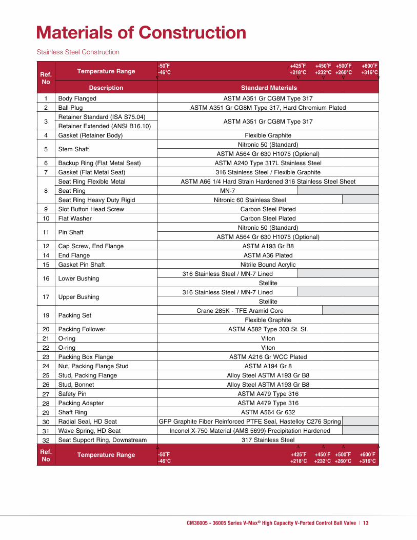
Stainless Steel Construction
Ref. No
Temperature Range-50oF +425oF +450oF +500oF +600oF-46°C +218°C +232°C +260°C +316°C
Description Standard Materials
1 Body Flanged ASTM A351 Gr CG8M Type 317
2 Ball Plug ASTM A351 Gr CG8M Type 317, Hard Chromium Plated
3Retainer Standard (ISA S75.04)
ASTM A351 Gr CG8M Type 317Retainer Extended (ANSI B16.10)
4 Gasket (Retainer Body) Flexible Graphite
5 Stem ShaftNitronic 50 (Standard)
ASTM A564 Gr 630 H1075 (Optional)
6 Backup Ring (Flat Metal Seat) ASTM A240 Type 317L Stainless Steel
7 Gasket (Flat Metal Seat) 316 Stainless Steel / Flexible Graphite
8
Seat Ring Flexible Metal ASTM A66 1/4 Hard Strain Hardened 316 Stainless Steel Sheet
Seat Ring MN-7
Seat Ring Heavy Duty Rigid Nitronic 60 Stainless Steel
9 Slot Button Head Screw Carbon Steel Plated
10 Flat Washer Carbon Steel Plated
11 Pin ShaftNitronic 50 (Standard)
ASTM A564 Gr 630 H1075 (Optional)
12 Cap Screw, End Flange ASTM A193 Gr B8
14 End Flange ASTM A36 Plated
15 Gasket Pin Shaft Nitrile Bound Acrylic
16 Lower Bushing316 Stainless Steel / MN-7 Lined
Stellite
17 Upper Bushing316 Stainless Steel / MN-7 Lined
Stellite
19 Packing SetCrane 285K - TFE Aramid Core
Flexible Graphite
20 Packing Follower ASTM A582 Type 303 St. St.
21 O-ring Viton
22 O-ring Viton
23 Packing Box Flange ASTM A216 Gr WCC Plated
24 Nut, Packing Flange Stud ASTM A194 Gr 8
25 Stud, Packing Flange Alloy Steel ASTM A193 Gr B8
26 Stud, Bonnet Alloy Steel ASTM A193 Gr B8
27 Safety Pin ASTM A479 Type 316
28 Packing Adapter ASTM A479 Type 316
29 Shaft Ring ASTM A564 Gr 632
30 Radial Seal, HD Seat GFP Graphite Fiber Reinforced PTFE Seal, Hastelloy C276 Spring
31 Wave Spring, HD Seat Inconel X-750 Material (AMS 5699) Precipitation Hardened
32 Seat Support Ring, Downstream 317 Stainless Steel
Ref. No
Temperature Range -50oF +425oF +450oF +500oF +600oF-46°C +218°C +232°C +260°C +316°C
∆ ∆∆ ∆ ∆
∆ ∆ ∆ ∆ ∆
Materials of Construction
14 | Dresser Masoneilan
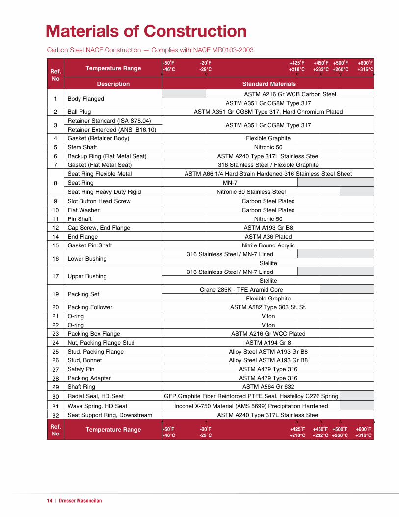
Carbon Steel NACE Construction — Complies with NACE MR0103-2003
Ref. No
Temperature Range-50oF -20oF +425oF +450oF +500oF +600oF-46°C -29°C +218°C +232°C +260°C +316°C
Description Standard Materials
1 Body FlangedASTM A216 Gr WCB Carbon Steel
ASTM A351 Gr CG8M Type 317
2 Ball Plug ASTM A351 Gr CG8M Type 317, Hard Chromium Plated
3Retainer Standard (ISA S75.04)
ASTM A351 Gr CG8M Type 317Retainer Extended (ANSI B16.10)
4 Gasket (Retainer Body) Flexible Graphite
5 Stem Shaft Nitronic 50
6 Backup Ring (Flat Metal Seat) ASTM A240 Type 317L Stainless Steel
7 Gasket (Flat Metal Seat) 316 Stainless Steel / Flexible Graphite
8
Seat Ring Flexible Metal ASTM A66 1/4 Hard Strain Hardened 316 Stainless Steel Sheet
Seat Ring MN-7
Seat Ring Heavy Duty Rigid Nitronic 60 Stainless Steel
9 Slot Button Head Screw Carbon Steel Plated
10 Flat Washer Carbon Steel Plated
11 Pin Shaft Nitronic 50
12 Cap Screw, End Flange ASTM A193 Gr B8
14 End Flange ASTM A36 Plated
15 Gasket Pin Shaft Nitrile Bound Acrylic
16 Lower Bushing316 Stainless Steel / MN-7 Lined
Stellite
17 Upper Bushing316 Stainless Steel / MN-7 Lined
Stellite
19 Packing SetCrane 285K - TFE Aramid Core
Flexible Graphite
20 Packing Follower ASTM A582 Type 303 St. St.
21 O-ring Viton
22 O-ring Viton
23 Packing Box Flange ASTM A216 Gr WCC Plated
24 Nut, Packing Flange Stud ASTM A194 Gr 8
25 Stud, Packing Flange Alloy Steel ASTM A193 Gr B8
26 Stud, Bonnet Alloy Steel ASTM A193 Gr B8
27 Safety Pin ASTM A479 Type 316
28 Packing Adapter ASTM A479 Type 316
29 Shaft Ring ASTM A564 Gr 632
30 Radial Seal, HD Seat GFP Graphite Fiber Reinforced PTFE Seal, Hastelloy C276 Spring
31 Wave Spring, HD Seat Inconel X-750 Material (AMS 5699) Precipitation Hardened
32 Seat Support Ring, Downstream ASTM A240 Type 317L Stainless Steel
Ref. No
Temperature Range -50oF -20oF +425oF +450oF +500oF +600oF-46°C -29°C +218°C +232°C +260°C +316°C
∆ ∆ ∆∆ ∆ ∆
∆ ∆ ∆ ∆ ∆ ∆
Materials of Construction

CM36005 - 36005 Series V-Max® High Capacity V-Ported Control Ball Valve | 15
Actuator Model 33, Size AC – inches [millimeters]
Actuator Model 33, Size B and C – inches [millimeters]
Dimensions

16 | Dresser Masoneilan
Valve Size
Actuator Size
A
B
C(1) Face-to-FaceD
E F G
Center-to-FaceH
in. DN SizeSq. In.
ANSI150
ANSI300
ANSI150
ANSI300
Standard ISA
S75.04(2)
Optional ASME
B16.10(3)
Standard ISA
S75.04(2)
Optional ASME
B16.10(3)
1 25 AC 30 2.74 2.74 8.06 4.25 4.88 4.00 5.00 10.70 8.50 10.53 2.12 3.12
1.5 40 AC 30 3.13 4.08 8.33 5.00 6.12 4.47 6.49 10.70 8.50 10.80 2.43 4.46
2 50AC 30 3.92 5.05 8.74 6.00 6.50 4.93 7.01 10.70 8.50 11.21 2.56 4.64
B 70 3.92 5.05 8.52 6.00 6.50 4.93 7.01 11.45 13.00 11.21 2.56 4.64
3 80B 70 4.64 4.64 10.24 7.50 8.25 6.54 8.00 11.45 13.00 12.93 3.59 5.06
C 140 4.64 4.64 10.24 7.50 8.25 6.54 8.00 15.07 17.50 12.93 3.59 5.06
4 100B 70 5.48 5.48 10.87 9.00 10.00 7.61 9.00 11.45 13.00 13.56 3.95 5.50
C 140 5.48 5.48 10.87 9.00 10.00 7.61 9.00 15.07 17.50 13.56 3.95 5.50
6 150 C 140 6.76 6.76 12.09 11.00 12.50 8.99 10.52 15.07 17.50 14.78 4.85 6.37
8 200 C 140 7.88 7.88 13.81 13.50 15.00 9.59 11.50 15.07 17.50 16.50 5.03 6.95
10 250 C 140 9.46 9.46 15.75 16.00 17.50 11.69 13.02 15.07 17.50 18.44 6.09 7.42
12 300 C 140 10.63 10.63 16.92 19.00 20.50 13.33 14.00 15.07 17.50 19.61 7.52 8.19
Actuator Model 33, Sizes AC, B and C (inches)
Valve Size
Actuator Size
A
B
C(1) Face-to-FaceD
E F G
Center-to-FaceH
in. DN SizeSq. cm
ANSI150
ANSI300
ANSI150
ANSI300
Standard ISA
S75.04(2)
Optional ASME
B16.10(3)
Standard ISA
S75.04(2)
Optional ASME
B16.10(3)
1 25 AC 194 69.60 69.60 204.72 107.95 123.95 101.60 127.00 271.78 215.90 267.46 53.85 79.25
1.5 40 AC 194 79.50 103.63 211.58 127.00 155.45 113.54 164.85 271.78 215.90 274.32 61.72 113.28
2 50AC 194 99.57 128.27 222.00 152.40 165.10 125.22 178.05 271.78 215.90 284.73 65.02 117.86
B 452 99.57 128.27 216.41 152.40 165.10 125.22 178.05 290.83 330.20 284.73 65.02 117.86
3 80B 452 117.86 117.86 260.10 190.50 209.55 166.12 203.20 290.83 330.20 328.42 91.19 128.52
C 903 117.86 117.86 260.10 190.50 209.55 166.12 203.20 382.78 444.50 328.42 91.19 128.52
4 100B 452 139.19 139.19 276.10 228.60 254.00 193.29 228.60 290.83 330.20 344.42 100.33 139.70
C 903 139.19 139.19 276.10 228.60 254.00 193.29 228.60 382.78 444.50 344.42 100.33 139.70
6 150 C 903 171.70 171.70 307.09 279.40 317.50 228.35 267.21 382.78 444.50 375.41 123.19 161.80
8 200 C 903 200.15 200.15 350.77 342.90 381.00 243.59 292.10 382.78 444.50 419.10 127.76 176.53
10 250 C 903 240.28 240.28 400.05 406.40 444.50 296.93 330.71 382.78 444.50 468.38 154.69 188.47
12 300 C 903 270.00 270.00 429.77 482.60 520.70 338.58 355.60 382.78 444.50 498.09 191.01 208.03
Actuator Model 33, Sizes AC, B and C (millimeters)
Notes:1. Conforms to ASME/ANSI Standard B16.5 - 1996 “Pipe Flanges and Flange Fittings”2. Conforms to ISA Standard S75.043. Conforms to ASME Standard B16.10 - 1992 (formerly ANSI Standard B16.10 - 1973) Short Pattern Ball. Available for ANSI 150 Class Valves ONLY
Dimensions

CM36005 - 36005 Series V-Max® High Capacity V-Ported Control Ball Valve | 17
DimensionsActuator Model 31/32, Size D – inches [millimeters]

18 | Dresser Masoneilan
Valve Size
Actuator Size
A
B
C(1) Face-to-FaceD
E F G
Center-to-FaceH
in. DN SizeSq. In.
ANSI150
ANSI300
ANSI150
ANSI300
Standard ISA
S75.04(2)
Optional ASME
B16.10(3)
Standard ISA
S75.04(2)
Optional ASME
B16.10(3)
3 80 D 60 4.64 4.64 12.12 7.50 8.25 6.54 8.00 19.78 12.75 13.88 3.59 5.06
4 100 D 60 5.48 5.48 12.75 9.00 10.00 7.61 9.00 19.78 12.75 14.51 3.95 5.50
6 150 D 60 6.76 6.76 14.06 11.00 12.50 8.99 10.52 19.78 12.75 15.82 4.85 6.37
8 200 D 60 7.88 7.88 15.69 13.50 15.00 9.59 11.50 19.78 12.75 17.45 5.03 6.95
10 250 D 60 9.46 9.46 17.63 16.00 17.50 11.69 13.02 19.78 12.75 19.39 6.09 7.42
12 300 D 60 10.63 10.63 18.80 19.00 20.50 13.33 14.00 19.78 12.75 20.56 7.52 8.19
Actuator Model 31/32, Size D (inches)
Valve Size
Actuator Size
A
B
C(1) Face-to-FaceD
E F G
Center-to-FaceH
in. DN SizeSq. cm
ANSI150
ANSI300
ANSI150
ANSI300
Standard ISA
S75.04(2)
Optional ASME
B16.10(3)
Standard ISA
S75.04(2)
Optional ASME
B16.10(3)
3 80 D 387 117.86 117.86 307.85 190.50 209.55 166.12 203.20 502.41 323.85 352.55 91.19 128.52
4 100 D 387 139.19 139.19 323.85 228.60 254.00 193.29 228.60 502.41 323.85 368.55 100.33 139.70
6 150 D 387 171.70 171.70 357.12 279.40 317.50 228.35 267.21 502.41 323.85 401.83 123.19 161.80
8 200 D 387 200.15 200.15 398.53 342.90 381.00 243.59 292.10 502.41 323.85 443.23 127.76 176.53
10 250 D 387 240.28 240.28 447.80 406.40 444.50 296.93 330.71 502.41 323.85 492.51 154.69 188.47
12 300 D 387 270.00 270.00 477.52 482.60 520.70 338.58 355.60 502.41 323.85 522.22 191.01 208.03
Actuator Model 31/32, Size D (millimeters)
Notes:1. Conforms to ASME/ANSI Standard B16.5 - 1996 “Pipe Flanges and Flange Fittings”2. Conforms to ISA Standard S75.043. Conforms to ASME Standard B16.10 - 1992 (formerly ANSI Standard B16.10 - 1973) Short Pattern Ball. Available for ANSI 150 Class Valves ONLY
Dimensions

CM36005 - 36005 Series V-Max® High Capacity V-Ported Control Ball Valve | 19
Valve Size Actuator
Valve and Actuator Assembly Weights (without Manual Override)Manual
OverrideStandard ISA S75.04 Face-to-FaceOptional ASME B16.10
Face-to-Face
ANSI Class 150 Flanged
ANSI Class 300 Flanged
ANSI Class 150 Flanged ONLY
Add to Valve / Actuator Weight
in. DN Model Size lbs Kg lbs Kg lbs Kg lbs Kg
1 25 33 AC 50 22 53 24 50 23 7 3
1.5 40 33 AC 54 24 61 27 56 25 7 3
2 5033 AC 60 27 81 37 63 29 7 3
33 B 101 46 122 55 103 47 27 12
3 80
33 B 124 56 134 61 128 58 27 12
33 C 182 82 192 87 186 84 27 12
31/32 D 227 103 237 107 231 105 12 5
4 100
33 B 147 67 166 75 152 69 27 12
33 C 205 93 224 101 210 95 27 12
31/32 D 250 113 269 122 255 116 12 5
6 15033 C 250 114 288 131 260 118 27 12
31/32 D 295 134 333 151 305 138 12 5
8 20033 C 303 137 359 163 326 148 27 12
31/32 D 348 158 404 183 371 168 12 5
10 25033 C 393 178 416 189 480 217 27 12
31/32 D 438 199 461 209 525 238 12 5
12 30033 C 520 236 540 245 642 291 27 12
31/32 D 565 256 585 265 687 312 12 5
Assembly Weights

CM36005 09/10
www.dresser.com
Dresser Masoneilan Dresser, Inc., Flow Technologies 10343 Sam Houston Park Drive Houston, Texas 77064 U.S.A T. +1-281-671-1640F. +1-281-671-1735E. [email protected]
DIRECT SALES OFFICE LOCATIONS
About Dresser MasoneilanDresser Masoneilan, headquartered in Houston, Texas, has been the leading global partner in process control valves and solutions for more than 100 years. A business segment of Dresser, Inc., the company delivers customized products, services and diagnostic solutions for oil and gas, process and power generation applications. www.dresser.com
© 2010 Dresser, Inc. All rights reserved.
BELGIUMPhone: +32-2-344-0970Fax: +32-2-344-1123
BRAZILPhone: +55-11-2146-3600Fax: +55-11-2146-3610
CANADAOntarioPhone: +905-335-3529Fax: +905-336-7628
CHINAPhone: +86-10-8486-4515Fax: +86-10-8486-5305
FRANCECourbevoiePhone: +33-1-4904-9000Fax: +33-1-4904-9010
GERMANYViersenPhone: +49-2162-8170-0Fax: +49-2162-8170-280
INDIAMumbaiPhone: +91-22-8354790Fax: +91-22-8354791New DelhiPhone: +91-11-2-6164175Fax: +91-11-5-1659635
ITALYPhone: +39-081-7892-111Fax: +39-081-7892-208
JAPANChiba Phone: +81-43-297-9222Fax: +81-43-299-1115
KOREAPhone: +82-2-2274-0748Fax: +82-2-2274-0794
MALAYSIAPhone: +60-3-2161-0322Fax: +60-3-2163-6312
MEXICOPhone: +52-5-310-9863Fax: +52-5-310-5584
THE NETHERLANDSPhone: +31-15-3808666Fax: +31-18-1641438
RUSSIAVeliky NovgorodPhone: +7-8162-55-7898Fax: +7-8162-55-7921MoscowPhone: +7 495-585-1276Fax: +7 495-585-1279
SAUDI ARABIAPhone: +966-3-341-0278Fax: +966-3-341-7624
SINGAPOREPhone: +65-6861-6100Fax: +65-6861-7172
SOUTH AFRICAPhone: +27-11-452-1550Fax: +27-11-452-6542
SOUTH & CENTRAL AMERICA AND THE CARIBBEANPhone: +55-12-2134-1201Fax: +55-12-2134-1238
SPAINPhone: +34-93-652-6430Fax: +34-93-652-6444
UNITED ARAB EMIRATESPhone: +971-4-8139-200Fax: +971-4-8838-038
UNITED KINGDOMWooburn GreenPhone: +44-1628-536300Fax: +44-1628-536319
UNITEDSTATESMassachusettsPhone: +1-508-586-4600Fax: +1-508-427-8971
CorpusChristi,TexasPhone: +1-361-881-8182Fax: +1-361-881-8246DresserDirectDeerPark,TexasPhone: +1-281-884-1000Fax: +1-281-884-1010DresserFlowTechnologiesHouston,TexasPhone: +1-281-671-1640Fax: +1-281-671-1735CaliforniaPhone: +1-562-941-7610Fax: +1-562-941-7810
About Dresser, Inc.Dresser Inc. is a global leader in providing highly- engineered infrastructure products for the global energy industry. Leading brand names within the Dresser portfolio include Dresser Wayne® retail fueling systems, Waukesha® natural gas-fired engines, Masoneilan® control valves, Consolidated® pressure relief valves, and ROOTS® blowers and rotary gas meters. The company has manufacturing and customer service facilities strategically located worldwide and a sales presence in more than 150 countries. www.dresser.com