specification dsp0114 status: final - dmtf
TRANSCRIPT

Specification DSP0114
STATUS: Final
Copyright © "2000, 2001" Distributed Management Task Force, Inc. (DMTF). All rights reserved.
DMTF is a not-for-profit association of industry members dedicated to promoting enterprise and systems management and interoperability. DMTF specifications and documents may be reproduced for uses consistent with this purpose by members and non-members, if correct attribution is given. As DMTF specifications may be revised from time to time, the particular version and release cited should always be noted."
A l e r t S t a n d a r d F o r m a t ( A S F ) S p e c i f i c a t i o n
Version 1.03 June 20, 2001
Abstract The term “system manageability” represents a wide range of technologies that enable remote system access and control in both OS-present and OS-absent environments. These technologies are primarily focused on minimizing on-site I/T maintenance, maximizing system availability and performance to the local user, maximizing remote visibility of (and access to) local systems by I/T managers, and minimizing the system power consumption required to keep this remote connection intact. The Distributed Management Task Force (DMTF) defines Desktop Management Interface (DMI) and Common Information Model (CIM) interfaces that operate when the managed client is fully operational in its OS-present environment. This specification defines remote control and alerting interfaces that best serve the clients’ OS-absent environments.
Editor
Kevin Cline Intel Corporation
For the DMTF Pre-OS Working Group

Alert Standard Format (ASF) Specification 1.03
DSP0114.doc 20 June 2001 Page ii
Change History:
Version Date Author Changes
1.0a October 13, 2000
K. Cline
First Draft release for the DMTF Member Comment phase.
1.0.b December 13, 2000
K. Cline
Updated for the following Member Comments: • ASFCR001 Add RMCP to Terminology Table • ASFCR002 Add URL to Terminology Table, pointing to
Enterprise Numbers • ASFCR003 Corrections to “Using the Message Tag”
section. • ASFCR004 Remove “header” comment from RMCP section
3.2.3.1 • ASFCR005 Boot options “clear” clarification (3.2.3.1) • ASFCR006 Corrections to “C” style structures (4.1.2.6 and
4.1.2.7) • ASFCR007 Add suggested policies for firmware use of boot
options (5.2.1) • ASFCR009 Return OEM command capability to RMCP boot
options commands (3.2.3.1, 4.1.2.6, and 5.2.1.1).
• ASFCR010 Correct ASF IANA number in RMCP section (3.2.4).
1.0.c January 17, 2001
K. Cline
Updated for the following Member Comments: • ASFCR008 Add Asynchronous Notification SMBus
message (<need section numbers>). • ASFCR011 Clarify which device controls the de-assertion
bit of a the Event Offset field for Get Event Data command (5.1.1.1).
1.01 May 23, 2001 K. Cline
Accepted all previous changes and updated for the following Member Comments: • ASFCR013 Add System Firmware Error/Progress codes • ASFCR014 Clarifications found during ASD compliance
documentation • ASFCR015 Renumber checklists to produce sequential and
ascending-ordering. 1.02 May 30, 2001 K.
Cline Updated for the following Member Comments: • ASFCR012 SMBus 2.0 Compliance update
1.03 June 13, 2001 K. Cline
Updated for the following Member Comments: • ASFCR016 Example correction in section 5.1.1.2
1.03 Final
June 19, 2001 K. Cline
Document status -> Final
June 20, 2001 K. Cline
Name change to Alert Standard Format.

Alert Standard Format (ASF) Specification 1.03
DSP0114.doc 20 June 2001 Page iii
Table of Contents
1 Introduction........................................................................................2
1.1 Target Audience........................................................................................................2 1.2 Related Documents ...................................................................................................2 1.3 Data Format ..............................................................................................................3 1.4 Terminology ..............................................................................................................3
2 Overview.............................................................................................5
2.1 Principal Goals ..........................................................................................................5 2.2 Problem Statement ....................................................................................................5 2.3 Solution ....................................................................................................................5 2.4 Known Limitations .....................................................................................................7
3 Network Protocols.............................................................................8
3.1 Transmit Protocol (PET) .............................................................................................8 3.1.1 PET Frame Behavior ......................................................................................8
3.1.1.1 PET Re-transmission ......................................................................................8 3.1.1.2 Transient Event Handling................................................................................8
3.1.2 Agent Address Field........................................................................................8 3.1.3 Specific Trap Field ..........................................................................................8 3.1.4 Variable Bindings Fields ..................................................................................8
3.1.4.1 PET Frame Content Sources.........................................................................10 3.1.5 Recommended PET Frame Values ................................................................13
3.1.5.1 Environmental Events ...................................................................................13 3.1.5.2 System Firmware Error Events ......................................................................14 3.1.5.3 System Firmware Progress Events ................................................................15 3.1.5.4 OS Events ...................................................................................................16 3.1.5.5 System Heartbeat .........................................................................................17 3.1.5.6 System Boot Failure .....................................................................................17
3.2 Remote Management and Control Protocol (RMCP) ..................................................18 3.2.1 RMCP UDP Port Numbers ............................................................................18 3.2.2 RMCP Packet Format ...................................................................................18
3.2.2.1 RMCP Acknowledge .....................................................................................19 3.2.2.2 RMCP Header..............................................................................................20 3.2.2.3 ASF RMCP Data ..........................................................................................21
3.2.3 ASF RMCP Message Types ..........................................................................23 3.2.3.1 Reset (10h), Power-up (11h), and Power Cycle Reset (13h)............................23 3.2.3.2 Unconditional Power-Down (12h) ..................................................................25 3.2.3.3 Presence Pong (40h) ....................................................................................26 3.2.3.4 Capabilities Response (41h) .........................................................................26 3.2.3.5 System State Response (42h) .......................................................................28 3.2.3.6 Presence Ping (80h).....................................................................................29 3.2.3.7 Capabilities Request (81h) ............................................................................29 3.2.3.8 System State Request (82h) .........................................................................29
3.2.4 RMCP Usage Scenarios ...............................................................................30 3.2.5 RMCP Considerations for LAN Alert-sending Devices .....................................33

Alert Standard Format (ASF) Specification 1.03
DSP0114.doc 20 June 2001 Page iv
4 Firmware Interfaces ....................................................................... 34 4.1 ACPI Definitions ......................................................................................................34
4.1.1 Control Methods ...........................................................................................34 4.1.1.1 Get Power-on Wait Time (GPWT)..................................................................35 4.1.1.2 Set Power-on Wait Time (SPWT) ..................................................................35
4.1.2 ASF! Description Table .................................................................................35 4.1.2.1 ASF_INFO ...................................................................................................37 4.1.2.2 ASF_ALRT...................................................................................................39 4.1.2.3 ASF_ALERTDATA .......................................................................................40 4.1.2.4 ASF_RCTL ..................................................................................................41 4.1.2.5 ASF_CONTROLDATA ..................................................................................42 4.1.2.6 ASF_RMCP .................................................................................................42 4.1.2.7 ASF_ADDR..................................................................................................44
4.2 SMBIOS Structures .................................................................................................45 4.2.1 System Information (Type 1)..........................................................................45
4.3 SMBus Serial EEPROM (SEEPROM).......................................................................45 4.3.1 Fixed SMBus Addresses (SEEPROM Record Type 06h) .................................46 4.3.2 ASF Legacy-Device Alerts (SEEPROM Record Type 07h) ..............................46 4.3.3 ASF Remote Control (SEEPROM Record Type 08h).......................................46
5 ASF SMBus Messages................................................................... 48
5.1 Alert-related Messages ............................................................................................49 5.1.1 ASF-Sensor Poll Messages ...........................................................................49
5.1.1.1 Get Event Data.............................................................................................50 5.1.1.2 Get Event Status ..........................................................................................52
5.1.2 Asynchronous Alert Notification to SMBus Host ..............................................53 5.1.3 Alert Configuration Message..........................................................................54 5.1.4 Watchdog Timer Support...............................................................................56
5.1.4.1 Start Watchdog Timer...................................................................................56 5.1.4.2 Stop Watchdog Timer ...................................................................................57
5.1.5 Push Alert Messages ....................................................................................57 5.1.5.1 Message with Retransmission .......................................................................57 5.1.5.2 Message without Retransmission ..................................................................58
5.2 Boot Option Messages .............................................................................................58 5.2.1 Get Boot Options ..........................................................................................58
5.2.1.1 Return Boot Options Response .....................................................................59 5.2.1.2 No Boot Options Response...........................................................................59
5.2.2 Boot Options Clear .......................................................................................59 5.3 Discovery and Status Messages ...............................................................................60
5.3.1 Device Type Poll Message ............................................................................60 5.3.2 Set System State Message ...........................................................................60
5.4 Remote-Control Device Action Message ...................................................................61 5.5 Legacy Sensor Device Alert Poll Message ................................................................61
6 SMBus Device Characteristics..................................................... 62
6.1 Legacy Sensor Devices ...........................................................................................62 6.1.1 Sensor Requirements ...................................................................................62 6.1.2 Usage of Firmware Legacy Sensor Device Alert Information ............................63
6.2 ASF-Sensor Devices ...............................................................................................64

Alert Standard Format (ASF) Specification 1.03
DSP0114.doc 20 June 2001 Page v
6.2.1 Device Identification ......................................................................................64 6.2.2 Event Generation and Clearing ......................................................................65 6.2.3 Alert Status ..................................................................................................65 6.2.4 Device Power On Reset Time........................................................................66
6.3 Remote Control Device............................................................................................66 6.3.1 Device Requirements....................................................................................66 6.3.2 Usage of Firmware Remote Control Device Information ..................................66 6.3.3 Remote Control Functions .............................................................................66
Appendix A Additions to PET Specification 1.0......................... 69 A.1 Modem Support .......................................................................................................69 A.2 Battery Sensor ........................................................................................................69 A.3 System Firmware Error/Progress Descriptor..............................................................69 A.4 Device Relative Entity Instances ...............................................................................69 A.5 Event Source Type ..................................................................................................70 A.6 Sensor Type = 23h (Watchdog 2) Updates ................................................................70 A.7 IPMI 1.0 Entity IDs ...................................................................................................70 A.8 Entity and Sensor support for Alert Sending Devices .................................................71
Appendix B ASF Entity Section Map............................................ 72 B.1 Alert Sending Device...............................................................................................72 B.2 Legacy Sensor ........................................................................................................72 B.3 ASF Sensor ............................................................................................................72 B.4 Remote Control Device............................................................................................73 B.5 Firmware ................................................................................................................73 B.6 Operating System....................................................................................................73 B.7 Local Alert Configuration Software ............................................................................73 B.8 Remote Console Software .......................................................................................74
Appendix C ASF Entity Function Checklists .............................. 75 C.1 Alert Sending Device...............................................................................................75 C.2 Local Alert-Sending Device Configuration Software ...................................................76 C.3 Legacy Sensor ........................................................................................................77 C.4 ASF Sensor ............................................................................................................77 C.5 Remote Control Device............................................................................................77 C.6 System Firmware ....................................................................................................78 C.7 Management Console Software................................................................................79

Alert Standard Format (ASF) Specification 1.03
DSP0114.doc 20 June 2001 Page 2 of 79
1 Introduction
The term “system manageability” represents a wide range of technologies that enable remote system access and control in both OS-present and OS-absent environments. These technologies are primarily focused on minimizing on-site I/T maintenance, maximizing system availability and performance to the local user, maximizing remote visibility of (and access to) local systems by I/T managers, and minimizing the system power consumption required to keep this remote connection intact. The Distributed Management Task Force (DMTF) defines Desktop Management Interface (DMI) and Common Information Model (CIM) interfaces that operate when the managed client is fully operational in its OS-present environment. This specification defines remote control and alerting interfaces that best serve the clients’ OS-absent environments.
1.1 Target Audience Following are the target audience for this specification:
• OEMs and ISVs developing platform firmware
• OEMs and IHVs developing SMBus devices
• OEMs and ISVs developing system management software
• OEMs and IHVs developing communication devices, e.g. Ethernet controllers or modems
1.2 Related Documents This document uses acronyms to reference other documents. For example, the acronym IPMI_1.0 refers to the Intelligent Platform Management Interface, Version 1.0. Acronyms are unique and enclosed in square brackets [IPMI_1.0]. For detailed information about the document referenced by an acronym, see the associated URL.
• [ACPI] Advanced Configuration and Power Interface Specification, 2.0, 27 July 2000, http://www.teleport.com/~acpi/spec.htm
• [RFC1157] A Simple Network Management Protocol, http://www.ietf.org/rfc/rfc1157.txt
• [CIM] CIM Standards, http://www.dmtf.org/spec/cims.html
• [IPMI_1.0] Intelligent Platform Management Interface Specification v1.0, rev 1.1, August 26, 1999, http://developer.intel.com/design/servers/ipmi/
• [RFC1188] IP and ARP on FDDI Networks, http://www.ietf.org/rfc/rfc1180.txt
• [FRU] IPMI Field Replaceable Unit (FRU) Information Storage Definition, v1.0, 16 September 1998, ftp://download.intel.com/design/servers/ipmi/fru1010.pdf
• [MTLS] Metolious ACPI/Manageability Specification, v1.0, 30 April 1999, http://developer.intel.com/ial/metolious/index.htm
• [NDCPM] Network Device Class Power Management Reference Specification, v1.0a, 21 November 1997, http://www.microsoft.com/hwdev/specs/PMref/PMnetwork.htm
• [PET_1.0] Platform Event Trap Specification, v1.0, 7 December 1998, ftp://download.intel.com/design/servers/ipmi/pet100.pdf
• [PET] Platform Event Trap Specification, v1.1, TBD, ftp://download.intel.com/design/servers/ipmi/TBD
• [SCMIS] SMBus Control Method Interface Specification, v1.0, 10 December 1999, http://www.smbus.org/specs/index.html
• [SMBIOS] System Management BIOS Reference Specification, v2.3.1, 16 March 1999. ftp://download.intel.com/ial/wfm/smbios.pdf
• [SMBUS_2.0] System Management Bus (SMBus) Specification, v2.0, 03 August 2000, http://www.smbus.org/specs/index.html
• [RFC_UDP] User Datagram Protocol, RFC 768, http://www.ietf.org/rfc/rfc0768.txt

Alert Standard Format (ASF) Specification 1.03
DSP0114.doc 20 June 2001 Page 3 of 79
1.3 Data Format All numbers specified in this document are in decimal format unless otherwise indicated. A number preceded by ‘0x’ or followed by the letter ‘h’ indicates hexadecimal format, and a number followed by the letter ‘b’ indicates binary format. For example, the numbers 10, 0x0A, 0Ah, and 1010b are equivalent.
One exception is section 5. The values associated with the Wr, Command, Byte Count, Sub-command, Version Number, A, and ~A fields are each specified in binary format with no trailing letter ‘b’.
1.4 Terminology Term Description
ACPI Advanced Configuration and Power Interface.
AoL Alert on LAN™
Alert-sending device
This term, used throughout this document, refers to a communications device that is capable of sending ASF-defined alerts.
ASL ACPI Source Language
ASF IANA Within this document, refers to the IANA-assigned Enterprise Number for ASF: 4542 (decimal) or 11BEh.
CIM Common Information Model
DMTF Distributed Management Task Force, http://www.dmtf.org
DMI Desktop Management Interface
GUID Globally Unique Identifier, synonymous with UUID (Universally Unique Identifier).
IANA Internet Assigned Numbers Authority, http://www.iana.org. This is the entity that assigns Enterprise Numbers; see http://www.isi.edu/in-notes/iana/assignments/enterprise-numbers for the current number assignments.
IHV Independent Hardware Vendor
IP Internet Protocol
IPMI Intelligent Platform Management Interface. See http://developer.intel.com/design/servers/ipmi/spec.htm .
ISV Independent Software Vendor
NIC Network Interface Card
NBO Network Byte Order. Refers to the order in which the bytes of a multi-byte number are transmitted on a network — most significant byte first. This might be different than the order in which the number is stored in memory, depending on the processor architecture.
OEM Original Equipment Manufacturer
OS Operating System.
OS-absent Refers to a system’s pre-boot, low-power, and OS-hung environments.
PCI Peripheral Components Interface, see http://www.pcisig.com
PDU Protocol Data Unit
PEC Packet Error Code.
PET Platform Event Trap. See http://developer.intel.com/design/servers/ipmi/spec.htm .
RFC Request For Comment
RMCP Remote Management and Control Protocol, see 3.2 Remote Management and Control Protocol (RMCP) in this document for further information.
SEEPROM Serial Electrically-Erasable Programmable Read-Only Memory
SMBus System Management Bus. See http://www.smbus.org

Alert Standard Format (ASF) Specification 1.03
DSP0114.doc 20 June 2001 Page 4 of 79
Term Description
SNMP Simple Network Management Protocol.
UTC Universal Time Coordinated. Greenwich Mean Time (GMT) updated with leap seconds.

Alert Standard Format (ASF) Specification 1.03
DSP0114.doc 20 June 2001 Page 5 of 79
2 Overview
Alerting technologies provide advance warning and system failure indication from managed clients to remote management consoles. Initial generations of this technology — like the IBM/Intel Alert on LAN™ (AoL) implementations — provided remote notification of client system states and hardware or software failures without regard to operating system or system power state. The Intelligent Platform Management Interface initiative, led by Intel and others, subsequently provided an open alert interface: the Platform Event Trap. Management console providers and system OEMs were faced with the possibility of supporting multiple alerting interfaces. Once a system alert provides its warning or error report, the next step in remote system manageability is to allow corrective action to be taken — these actions include the ability to remotely reset or power-on or -off the client system. When the system is in an OS-present state, these actions can be provided by Common Information Model (CIM) interfaces [CIM] that interact with the local system and provide orderly shutdown capabilities. This specification provides similar functionality when the system is in an OS-absent state, as added by the second generation of the IBM/Intel AoL technologies.
2.1 Principal Goals The principal goal of this specification is to define standards-based interfaces with which vendors of alerting and corrective -action offerings can implement products and ensure interoperability. These vendors include:
• Add-in card suppliers
• SMBus sensor suppliers
• Communication controller suppliers
• System vendors
• Operating system vendors, with a primary focus on operating systems which are ACPI-aware.
• Management application vendors
The standards-based protocols (e.g. SNMP, UDP) upon which this specification’s interfaces are built are lightweight, bit-based information carriers since this specification anticipates that the majority of the ASF client implementation will be hardware and/or firmware based. CIM-based configuration methods can provide the abstraction layer between OS-present XML implementations and ASF-defined low-level primitives.
2.2 Problem Statement Multiple solutions exist in the industry today, resulting in a loss of interoperability in system alert and corrective-action offerings.
2.3 Solution An Alerting System consists of a client system (or systems) and a management console that both monitors and controls the clients. An ASF-aware client provides the following interfaces to allow interoperability between the client and its management console:
1. the alert messages transmitted by the client system 2. the remote maintenance requests sent to the client system and the associated responses 3. the data description of the client’s system-specific capabilities and characteristics
4. the software used to configure or control the client system in an OS-present state An additional level of interoperability occurs between a client system’s alerting components:

Alert Standard Format (ASF) Specification 1.03
DSP0114.doc 20 June 2001 Page 6 of 79
1. the system firmware methods used to communicate system capabilities to an alert-capable add-in card’s OS-present configuration software
2. the format of the messages sent between the add-in card, the local system host, and local system sensors
The following graphic gives a pictorial portrayal of these components.
When the system owner adds an alert-sending device (e.g. an Ethernet add-in card) to an ASF-capable managed client, the alert-sending device must be configured with the client’s specific hardware configuration before it can properly issue alerts and respond to remote maintenance requests. To accomplish this, the client system requires one good boot to an OS-present environment to allow the device’s configuration software to run and store system-specific information into the device’s non-volatile storage. In an ACPI-aware OS-present environment, the alert-sending device’s configuration software interrogates the client’s configuration data to retrieve information required for any alert messages to be sent and stores that information into the device’s non-volatile storage for use in the OS-absent environment: 1. The client’s ACPI implementation contains its ASF Capabilities, including the IANA
Manufacturer ID and System ID 2. The client’s SMBIOS structure-table contains the system GUID (or UUID) 3. The operating system has assigned a TCP/IP address to the alert-sending device
4. How much time the alert-sending device waits before issuing a system boot-failure alert. The configuration software also provides an interface to allow the system owner to identify the TCP/IP address of the management console to which any alert messages are to be sent by this managed client. During this OS-present configuration process, the managed client’s optional ASF configuration is also determined and stored in the alert-sending device’s non-volatile storage:
Alerting System Components
R
Sensor Chipset System Firmware/BIOS
Sensor Driver
Local Add-In Card
Alerting Driver
SMBus Driver
NIC Driver
Remote Console Message Formats
← Tx Rx →
Local System Physical Media
Control/ Config Schema
SMBus Message Formats
Local System Details Sensor Characteristics
Local System Details

Alert Standard Format (ASF) Specification 1.03
DSP0114.doc 20 June 2001 Page 7 of 79
1. If the client includes legacy SMBus sensors, the addressing and configuration information for each.
2. If the client supports remote-control operations, which ASF-defined features are supported. Once the system owner has configured the alert-sending device, the managed client is enabled to send alert messages and, optionally, respond to remote-control requests from a specified management console.
2.4 Known Limitations The following are known limitations of an ASF-enabled system:
1. After a change to the system’s hardware configuration, e.g. adding or removing a card, at least one good boot to the system’s OS-present environment is required for the ASF subsystem to properly operate. The OS-present environment is used to configure the ASF alert-sending device with information that is not known or easily determinable within the OS-absent environment, e.g. management console and local system TCP/IP addresses.
2. The OS-present control of system-specific ASF features is reduced if a non-ACPI-aware operating system is used, since ACPI provides current-generation “standard” methods for the OS-present environment to communicate with system firmware. Plug-and-play calling interfaces, such as those specified by [SMBIOS], are not easily supported in current-generation operating systems.
3. No standard security interfaces are currently defined to control the execution of ASF-RMCP messages by the client system. Implementers are discouraged from using security mechanisms within the RMCP packet structure, but to instead address security at the network infrastructure level (e.g. deployment schemes and firewalls). If implementers do in fact design-in RMCP security, it must be capable of being disabled for use with ASF solutions and management consoles that do not implement these proprietary security schemes.

Alert Standard Format (ASF) Specification 1.03
DSP0114.doc 20 June 2001 Page 8 of 79
3 Network Protocols
3.1 Transmit Protocol (PET) The ASF protocol for sending alerts from a managed client to a management console is the Platform Event Trap [PET].
3.1.1 PET Frame Behavior
3.1.1.1 PET Re-transmission An ASF alert-sending device retransmits each PET frame two (2) times for a total of three (3) transmissions per event; all three transmissions must occur within a 1-minute window and contain the same Sequence Number field. A management console should treat identical events it receives outside the 1-minute window as a new event.
Exceptions: No retransmission is performed when the PET frame issued by the alert-sending device is either the result of a General Push Alert Message without retransmission (see 5.1.5.2) or a System Heartbeat (see 3.1.5.5).
3.1.1.2 Transient Event Handling The managed client does not transmit transient events that happen when the alert network connection is down (or otherwise unavailable). ASF defines a transient event as one that transitions from an original state to another state and then back to the original state. For example, if a voltage event asserts and de-asserts while the connection is down, the client must not send any voltage event PET frames when the connection is re-established. This mode of operation gives ASF-aware management consoles a deterministic behavior of any PETs issued by a managed client.
3.1.2 Agent Address Field If the transport for the PET frame is IP, the Agent Address field in the Trap PDU must contain the IP address of the station that caused the PET event per [RFC1157]. If the transport is not IP, then the Agent Address is set per the RFC for that transport, e.g. RFC 1420 for IPX.
This specification requires that the alert -sending device support IP protocols; other transports are optional.
3.1.3 Specific Trap Field The specific trap field of the SNMP Trap header contains the main event information for the PET event.
3.1.4 Variable Bindings Fields The Variable Bindings Fields in a PET frame contain the system and sensor information for an event.
PET Variable Binding Field
Description
GUID The GUID is required for ASF alerts; the value is specified by the system’s SMBIOS implementation. See 4.2.1 System Information (Type 1) on page 45 for details.
Sequence Number
The Sequence Number is required; see section 3.1.1.1 for the rules on re-transmission.
Local Timestamp
The Local Timestamp is recommended.
UTC Offset The UTC offset is recommended if there is a Local Timestamp

Alert Standard Format (ASF) Specification 1.03
DSP0114.doc 20 June 2001 Page 9 of 79
PET Variable Binding Field
Description
Trap Source Type
The Trap Source Type is the device or software that originated the trap on the network. Normally it will be the NIC (50h), the System Management Card (58h), or the Modem (60h).
Event Source Type
The Event Source Type describes the originator of the event. The Event Source Type is ASF 1.0 (68h) for all PET frames defined by this specification. Event Source Type values in the range 68h to 6Fh are reserved by [PET] for ASF use: 68h ASF 1.0 Implementation 69h-6Fh Reserved for future assignment by this (ASF) specification.
Event Severity The Event Severity setting is met to give a management station an indication of the severity of the event in the PET Frame. Typical values are Monitor (0x01), Non Critical (0x08), or Critical Condition (0x10).
Sensor Device The Sensor Device is the SMBus address of the sensor that caused the event for the PET Frame. In the case of a poll, the address of the polled sensor is used. In the case of a push, the address of the pushing sensor is used. If there is no SMBus address associated to the event (e.g. a firmware error or firmware progress message), then the value is 0xFF (unspecified). If an SMBus address is represented in this field, bits 7 through 1 contain the address, and bit 0 is set to 0b.
Sensor Number The Sensor Number is used to identify a given instance of a sensor relative to the Sensor Device. Values of 00h and FFh identify that the Sensor Number is not specified.
Entity The Entity indicates the platform device or subsystem associated with the event, usually identifying a Field Replaceable Unit (FRU). For example, an over-temperature event with this field set to “Processor” indicates a processor over-temperature event.
Entity Instance When a system includes multiple device instances, e.g. a multi-processor system, Entity Instance identifies which unique device is associated with the event. For example, if a system has two processors, this field distinguishes between events associated with Processor #1 and Processor #2. A value of 00h in this field indicates that Entity Instance is unspecified.
Event Data The Event Type determines the Event Data. Some of the PET messages defined in this specification allow the inclusion of a variable number of event data bytes, to further describe the event. When event data is included, the first byte of event data (Event Data 1) defines the format of Event Data bytes 2 through 5 that follow, using the following enumerations: 00b Data not specified 01b Data conforms to standard definitions 10b Data conforms to OEM definitions 11b Reserved for future assignment ED1 Bit Range Description 7:6 Defines the format of Event Data 2 5:4 Defines the format of Event Data 3 3:2 Defines the format of Event Data 4 1:0 Defines the format of Event Data 5 Note: Values in Event Data bytes 6 through 8 are OEM-specific and outside the range of this specification.
Language Code The Language Code is used with the OEM Custom Fields. For PET frames that do not have any OEM specific data, the language code should be set to FFh (unspecified).
Manufacturer ID
The IANA Manufacturer ID associated with the alerting system. The value is specified by the system’s ACPI implementation, see 4.1.2.1 ASF_INFO on page 37 for details.
System ID The manufacturer associated with the alerting system assigns the system identifier. The value is specified by the system’s ACPI implementation, see 4.1.2.1 ASF_INFO on page 37 for details.

Alert Standard Format (ASF) Specification 1.03
DSP0114.doc 20 June 2001 Page 10 of 79
PET Variable Binding Field
Description
OEM Custom Fields
Whenever possible PET frames should use the error codes and values contained in the PET specification to describe events. The OEM Custom fields should only be used if the event cannot be expressed in a standard way. If there are no OEM Custom Fields, then the type field is set to C1h.
3.1.4.1 PET Frame Content Sources The following sections use this legend to provide a map to the information source for the various elements of a Platform Event Trap:
Hard-coded by Alert-Sending Device
SMBIOS Data SEEPROM Data Sensor Data
SMBus “Push Alert”
Message Data Determined by Alert-Sending Device (non-
constant)
ACPI Data
These abbreviations are used for PET fields within the following sections: TST Trap Source Type EST Event Source Type
SEV Severity SD Sensor Device S# Sensor Number
E Entity EI Entity Instance LC Language Code
Initial Firmware Timeout This information map applies to the initial timeout failure that an alert-sending device transmits if the reset-activated watchdog timer is not stopped by the managed client’s firmware.
Specific Trap Field Reserved Event Sensor Type Event Type Event Offset
Variable Bindings Fields GUID Seq# Local
Timestamp UTC Offset
TST
EST
SEV
SD
S#
E EI
Event Data LC
Manufacturer ID System ID
OEM C. F.

Alert Standard Format (ASF) Specification 1.03
DSP0114.doc 20 June 2001 Page 11 of 79
Polled Legacy Sensors — Specified by ACPI This information map applies to alerts issued by an alert-sending device based on that device’s detection of an active event upon polling a legacy sensor that is specified by the system’s ACPI implementation.
Specific Trap Field Reserved Event Sensor Type Event Type Event Offset
Variable Bindings Fields GUID Seq# Local
Timestamp UTC Offset
TST
EST
SEV
SD
S#
E EI
Event Data LC
Manufacturer ID System ID
OEM C. F.
Polled Legacy Sensors — Specified by SEEPROM Data This information map applies to alerts issued by an alert-sending device based on that device’s detection of an active event upon polling a legacy sensor that is specified by the system’s SEEPROM data.
Specific Trap Field Reserved Event Sensor Type Event Type Event Offset
Variable Bindings Fields GUID Seq# Local
Timestamp UTC Offset
TST
EST
SEV
SD
S#
E EI
Event Data LC
Manufacturer ID System ID
OEM C. F.

Alert Standard Format (ASF) Specification 1.03
DSP0114.doc 20 June 2001 Page 12 of 79
Polled ASF Sensors This information map applies to alerts issued by an alerting device based on that device’s detection of an active event upon polling an ASF-compliant sensor via the “Poll Alert Message With Event Data” SMBus command.
Specific Trap Field Reserved Event Sensor Type Event Type Event Offset
Variable Bindings Fields GUID Seq# Local
Timestamp UTC Offset
TST
EST
SEV
SD
S#
E EI
Event Data LC
Manufacturer ID System ID
OEM C. F.
“Pushed” Events This information map applies to alerts issued by an alerting device based on either receipt of a “Firmware Error, Firmware Progress, or General Push Alert Message” or the expiration of a watchdog timer after receipt of a “Firmware Watchdog Start Message”.
Specific Trap Field Reserved Event Sensor Type Event Type Event Offset
Variable Bindings Fields GUID Seq# Local
Timestamp UTC Offset
TST
EST
SEV
SD
S#
E EI
Event Data LC
Manufacturer ID System ID
OEM C. F.

Alert Standard Format (ASF) Specification 1.03
DSP0114.doc 20 June 2001 Page 13 of 79
3.1.5 Recommended PET Frame Values This section describes the format for various PET frames. A given managed client is not required to support all the listed PET frames, but if a client supports the event described by one of the listed PET frames, the client should format the PET frame as described in this section.
3.1.5.1 Environmental Events This table describes the Specific Trap Field values for common environmental events. An implementation has options as to whether it returns generic information that just indicates the criticality of the event, or whether it returns information also indicating that the event was triggered by a rising or falling condition on the monitored parameter, e.g. whether an over-temperature or under-temperature condition caused the event. The list is presented as a guide only. It is not intended to represent a complete list of the possible environmental events from a system. Management consoles that interpret events should be prepared to accept any of the possible specified Event Sensor Type, Event Type and Event Offset values documented by [PET].
The Entity for a given event varies according to what system device the environmental sensor is monitoring. For example, a typical managed client can have temperature monitoring associated with its system board and with the main processor. A thermal event associated with the system board will have Entity set to 7 (System Board) and Entity Instance set to 1 (Primary), while a thermal event associated with the processor will have Entity set to 3 (Processor) and Entity Instance set to 1 (Primary).
Description Event Sensor Type Event Type Event Offset
TEMPERATURE PROBLEMS
Generic Critical Temperature Problem
01h (Temperature) 02h (transition to Critical from less severe)
Generic Temperature Warning
07h (generic severity)
03h (transition to non-critical from less severe)
Over-Temperature Problem
09h (Upper Critical - going high)
Over-Temperature Warning
07h (Upper Non-Critical, going high)
Under-Temperature Problem
02h (Lower Critical - going low)
Under-Temperature Warning
01h (Threshold-based)
00h (Lower Non-Critical, going low)
VOLTAGE PROBLEMS
Generic Critical Voltage Problem
02h (Voltage) 07h (generic severity)
02h (transition to Critical from less severe)
Over-Voltage Problem 09h (Upper Critical - going high)
Under-Voltage Problem
01h (Threshold-based)
02h (Lower Critical - going low)

Alert Standard Format (ASF) Specification 1.03
DSP0114.doc 20 June 2001 Page 14 of 79
Description Event Sensor Type Event Type Event Offset
FAN PROBLEMS
Generic Critical Fan failure
04h (Fan) 07h (generic severity) 02h (transition to Critical from less severe)
Generic predictive Fan failure
03h (generic digital/discrete event)
01h (predictive failure asserted)
Fan Speed Problem (speed too low to meet chassis cooling spec’s)
02h (Lower Critical - going low)
Fan Speed Warning (Fan speed below expected speed. Cooling still adequate)
01h (Threshold-based)
00h (Lower Non-Critical, going low)
Case Intrusion. 05h (Physical Security [Chassis Intrusion])
6Fh (Sensor specific) 00h (General Chassis Intrusion)
3.1.5.2 System Firmware Error Events This document defines a standard set of system firmware errors that are reported in the Event Data 2 PET sub-field for Sensor Type 0Fh (System Firmware Error/Progress), Sensor-specific Offset 00h (Standard System Firmware Error):
Descriptor Code
Description
00h Unspecified.
01h No system memory is physically installed in the system.
02h No usable system memory, all installed memory has experienced an unrecoverable failure.
03h Unrecoverable hard-disk/ATAPI/IDE device failure.
04h Unrecoverable system -board failure.
05h Unrecoverable diskette subsystem failure.
06h Unrecoverable hard-disk controller failure.
07h Unrecoverable PS/2 or USB keyboard failure.
08h Removable boot media not found
09h Unrecoverable video controller failure
0Ah No video device detected.
0Bh Firmware ROM corruption detected
0Ch CPU VID Mismatch. One or more processors sharing the same voltage supply have mismatched voltage requirements.
0Dh CPU speed-matching failure.
0Eh to FFh Reserved for future definition by this specification.
This table describes the Specific Trap Field and Entity values associated with some typical system firmware errors. The Event Type sub-field for all these events is set to 6Fh (Sensor specific). See above or section 3.1.5.3 for the Event Data 2 field definitions for Event Offset values 00h and 01h, respectively.
Description Event Sensor Type
Event Offset Event Data 1/2
Entity
No system memory; memory missing
0Fh (System Firmware Error or Progress)
00h (System Firmware Error)
40h/01h 32d (Memory Device)

Alert Standard Format (ASF) Specification 1.03
DSP0114.doc 20 June 2001 Page 15 of 79
Description Event Sensor Type
Event Offset Event Data 1/2
Entity
No system memory; unrecoverable failure
0Fh (System Firmware Error or Progress)
00h (System Firmware Error)
40h/02h 32d (Memory Device)
Unrecoverable hard-disk failure.
0Fh (System Firmware Error or Progress)
00h (System Firmware Error)
40h/03h 4 (Disk or Disk Bay)
Unrecoverable system board failure.
0Fh (System Firmware Error or Progress)
00h (System Firmware Error)
40h/04h 7 (System board)
No bootable media. 1Eh (Boot Error) 00h (no bootable media)
40h/00h 00h (Unspecified)
Hang during option ROM initialization (specified via watchdog set command)
0Fh (System Firmware Error or Progress)
01h (System Firmware Hang)
40h/08h 11d (Add-in board)
Unrecoverable multi-processor configuration mismatch
0Fh (System Firmware Error or Progress)
00h (System Firmware Error)
40h/0Bh 3 (Processor)
3.1.5.3 System Firmware Progress Events This document defines a standard set of firmware progress codes that are reported in the Event Data 2 PET sub-field via Sensor Type 0Fh (System Firmware Error/Progress), Sensor-specific Offset either 01h (System Firmware Hang) or 02h (System Firmware Progress). Each descriptor is associated with a significant event within a system’s firmware bring-up sequence; the ordering of the events implies no specific sequencing.
Descriptor Code Description
00h Unspecified.
01h Memory initialization.
02h Hard-disk initialization
03h Secondary processor(s) initialization
04h User authentication
05h User-initiated system setup
06h USB resource configuration
07h PCI resource configuration
08h Option ROM initialization
09h Video initialization
0Ah Cache initialization
0Bh SM Bus initialization
0Ch Keyboard controller initialization
0Dh Embedded controller/management controller initialization
0Eh Docking station attachment
0Fh Enabling docking station
10h Docking station ejection
11h Disabling docking station
12h Calling operating system wake-up vector
13h Starting operating system boot process, e.g. calling Int 19h
14h Baseboard or motherboard initialization.
15h Reserved.

Alert Standard Format (ASF) Specification 1.03
DSP0114.doc 20 June 2001 Page 16 of 79
Descriptor Code Description
16h Floppy initialization.
17h Keyboard test.
18h Pointing device test
19h Primary processor initialization
1Ah to FFh Reserved for future definition by this specification.
This table describes the Specific Trap Field values for some system firmware progress events. The Event Type sub-field for each of these traps is set to 6Fh (Sensor-specific). Description Event Sensor
Type Event Offset Event
Data 1/2 Entity
System firmware started. The presence of this progress code indicates that at least one CPU is properly executing.
25h (Entity Presence)
00h (Entity Present)
40h/00h 34d (BIOS)
Starting memory initialization and test.
0Fh (Firmware Error or Progress)
02h (System Firmware Progress, entry)
40h/01h 32d (Memory Device)
Completed memory initialization and test.
0Fh (Firmware Error or Progress)
82h (System Firmware Progress, exit)
40h/01h 32d (Memory Device)
Starting hard-disk initialization and test.
0Fh (Firmware Error or Progress)
02h (System Firmware Progress, entry)
40h/02h 4 (Disk or Disk Bay)
Waiting for user-password entry. 0Fh (Firmware Error or Progress)
02h (System Firmware Progress, entry)
40h/04h 34d (BIOS)
Entering BIOS setup. 0Fh (Firmware Error or Progress)
02h (System Firmware Progress, entry)
40h/05h 34d (BIOS)
Starting system resource configuration, e.g. performing PCI configuration.
0Fh (Firmware Error or Progress)
02h (System Firmware Progress, entry)
40h/07h 34d (BIOS)
Starting option ROM initialization. 0Fh (Firmware Error or Progress)
02h (System Firmware Progress, entry)
40h/08h 11d (Add-in board)
Starting OS boot process (e.g. preparing to issue Int 19h)
0Fh (Firmware Error or Progress)
02h (System Firmware Progress, entry)
40h/13h 0 (Unspecified)
Starting secondary processor(s)’ initialization
0Fh (Firmware Error or Progress)
02h (System Firmware Progress, entry)
40h/03h 3 (Processor)
3.1.5.4 OS Events This table describes the Specific Trap Field values for some OS events. The variable-bindings Entity field for each of these traps is 35d (OS) and the Event Type field for each is 6Fh (Sensor specific). A timer-expiration event can generally be considered to indicate a hang associated with the software that was running when the expiration occurred.
Description Event Sensor Type Event Offset Event Data Fields

Alert Standard Format (ASF) Specification 1.03
DSP0114.doc 20 June 2001 Page 17 of 79
Description Event Sensor Type Event Offset Event Data Fields
OS Boot Failure
23h (Watchdog 2) 00h (Timer Expired)
ED1 40h to indicate that the ED2 field contains “interesting” data
ED2 03h to identify that no interrupt was generated and that the timer was monitoring an OS load process at the time of expiration
OS Hung 20h (OS Critical Stop)
10h (Run-time stop)
N/A
3.1.5.5 System Heartbeat ASF-enabled systems can provide the capability to send a periodic message indicating that the system is still present. A timer present in the alert-sending device controls the frequency of this message, which is referred to as a system heartbeat. The timer’s period is typically programmable, but the period must not exceed 10 minutes. The recommended default is one heartbeat per minute, and the alert-sending device’s OS-present configuration software provides methods through which to disable the heartbeat transmission and set the enabled heartbeat’s frequency timer. System Heartbeat messages are sent as single PET frames, and are not re-transmitted. If an alert-sending device supports this message, the following event -specific PET fields must be used:
Event Sensor Type Event Type Event Offset Entity
25h (Entity presence) 6Fh (Sensor specific) 00h (Device Present) 23d (System Chassis)
3.1.5.6 System Boot Failure A configured, ASF-enabled alert-sending device transmits a system boot failure alert if the system firmware does not issue an SMBus Stop Watchdog Timer command within the client’s Minimum Watchdog Reset Time (see 4.1.2.1). The alert-sending device starts its timer on the managed client’s transition to the point where main PCI power is good. Following are the event-specific PET fields associated with this alert:
PET Field Value
Event Sensor Type
23h (Watchdog 2)
Event Type 6Fh (Sensor specific)
Event Offset 00h (Timer Expired)
Event Severity 10h (Critical)
Sensor Device FFh (Unspecified)
Sensor Number FFh (Unspecified)
Entity 00h (Unspecified). This value is used since the root cause of the failure associated with the timer’s expiration is not known at the time of the alert.
Entity Instance 00h (Unspecified)
Event Data 4006h (ED2 valid, system boot failure).

Alert Standard Format (ASF) Specification 1.03
DSP0114.doc 20 June 2001 Page 18 of 79
3.2 Remote Management and Control Protocol (RMCP) RMCP (Remote Management and Control Protocol) is a UDP (User Datagram Protocol) based protocol used for client control functions when a managed client is in an OS-absent state. In this environment, RMCP packets are exchanged between a management console and a managed client; typical client control functions include operations such as reset, power-up, and power-down. The protocol is intentionally simple, to enable alert-sending devices’ firmware to easily parse the information in the absence of OS-present drivers. A management console uses RMCP methods as part of a two-tiered approach to managing client systems. The console should always use OS-present methods as the primary method to power down or reset a managed client, so that any shutdown operation is handled in an orderly fashion. Consoles should employ RMCP methods only if the managed client fails to respond to the OS-present methods, since the hardware-based RMCP methods could result in loss of data on the client system. An ASF-aware management console determines a managed client’s ASF-RMCP capabilities by issuing the following commands: 1) The console issues a Presence Ping command directed to the managed client; the ASF-
aware client then …
a) … acknowledges receipt of the RMCP message, so long as the RMCP ve rsion in the message’s header is a version supported by the client.
b) … responds with a Presence Pong message, setting the Supported Entities field (bits 3:0) to indicate its ASF version.
2) The console issues a Capabilities Request message to the managed client; the client … a) … acknowledges receipt of the RMCP message, so long as the RMCP version in the
message’s header is a version supported by the client. b) … responds with a Capabilities Response message, returning the system capabilities
previously configured into the alert -sending device’s non-volatile storage.
At this point, the console knows that the managed client is ASF-aware and which of the optional ASF-RMCP ‘Set’ commands are supported by the client — the client will acknowledge receipt of any unsupported command, but will disregard the command contents.
3.2.1 RMCP UDP Port Numbers There are two UDP ports reserved for RMCP use — port numbers 026Fh (623 decimal) and 0298h (644 decimal):
Port Usage 026Fh This port is used for all communications for ASF version 1.0. 0298h Reserved for future definition by this specification.
Each of these ports is a destination port on the managed client.
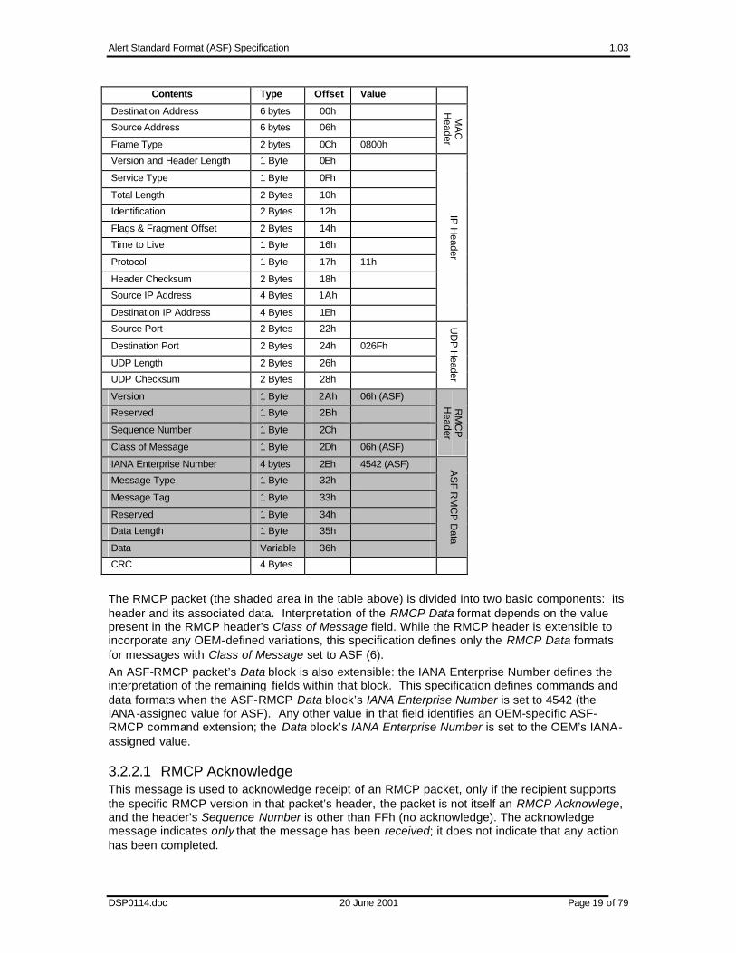
3.2.2 RMCP Packet Format The following table describes the complete network frame that includes RMCP, using an 802.3 Ethernet frame as the example. RMCP is media independent and, depending on the medium, the associated header fields will be different. All the data fields specified in this message are in network byte order. This specification defines the format of the shaded fields in the frame described below. Within the table that follows, a Contents field that has non-blank Value field defines the method through which the following frame contents are determined. For example, if the MAC Header’s Frame Type is set to 0800h then the frame element that follows the MAC Header is an IP Header.
Contents Type Offset Value
Alert Standard Format (ASF) Specification 1.03
DSP0114.doc 20 June 2001 Page 19 of 79
Contents Type Offset Value
Destination Address 6 bytes 00h
Source Address 6 bytes 06h
Frame Type 2 bytes 0Ch 0800h
MA
C
Header
Version and Header Length 1 Byte 0Eh
Service Type 1 Byte 0Fh
Total Length 2 Bytes 10h
Identification 2 Bytes 12h
Flags & Fragment Offset 2 Bytes 14h
Time to Live 1 Byte 16h
Protocol 1 Byte 17h 11h
Header Checksum 2 Bytes 18h
Source IP Address 4 Bytes 1Ah
Destination IP Address 4 Bytes 1Eh
IP H
eader
Source Port 2 Bytes 22h
Destination Port 2 Bytes 24h 026Fh
UDP Length 2 Bytes 26h
UDP Checksum 2 Bytes 28h
UD
P H
eader
Version 1 Byte 2Ah 06h (ASF)
Reserved 1 Byte 2Bh
Sequence Number 1 Byte 2Ch
Class of Message 1 Byte 2Dh 06h (ASF)
RM
CP
H
eader
IANA Enterprise Number 4 bytes 2Eh 4542 (ASF)
Message Type 1 Byte 32h
Message Tag 1 Byte 33h
Reserved 1 Byte 34h
Data Length 1 Byte 35h
Data Variable 36h
AS
F RM
CP
Data
CRC 4 Bytes
The RMCP packet (the shaded area in the table above) is divided into two basic components: its header and its associated data. Interpretation of the RMCP Data format depends on the value present in the RMCP header’s Class of Message field. While the RMCP header is extensible to incorporate any OEM-defined variations, this specification defines only the RMCP Data formats for messages with Class of Message set to ASF (6). An ASF-RMCP packet’s Data block is also extensible: the IANA Enterprise Number defines the interpretation of the remaining fields within that block. This specification defines commands and data formats when the ASF-RMCP Data block’s IANA Enterprise Number is set to 4542 (the IANA-assigned value for ASF). Any other value in that field identifies an OEM-specific ASF-RMCP command extension; the Data block’s IANA Enterprise Number is set to the OEM’s IANA-assigned value.
3.2.2.1 RMCP Acknowledge This message is used to acknowledge receipt of an RMCP packet, only if the recipient supports the specific RMCP version in that packet’s header, the packet is not itself an RMCP Acknowlege, and the header’s Sequence Number is other than FFh (no acknowledge). The acknowledge message indicates only that the message has been received; it does not indicate that any action has been completed.

Alert Standard Format (ASF) Specification 1.03
DSP0114.doc 20 June 2001 Page 20 of 79
In a typical interaction, the recipient of an RMCP packet acknowledges the sender by returning the received RMCP header with the MSB (most significant bit) of the “Class of Message” field set to indicate an acknowledgement. Specifically, the recipient returns to the sender the first three bytes from the received RMCP header (version, sequence number and reserved fields) with the fourth byte modified to indicate that the packet represents an RMCP Acknowledge. The following table describes the acknowledge’s format: Contents Type Offset Value
Version 1 byte 00h Copied from the received message
Reserved 1 byte 01h Copied from the received message.
Sequence Number 1 byte 02h Copied from the received message.
Class of Message 1 byte 03h Bit(s) Description 7 Set to 1 to indicate acknowledgement. 6:0 Copied from the header of the received message.
RM
CP
Header for
Acknow
ledge
Notes:
1. The RMCP Acknowledge does not have an RMCP Data block; only the RMCP Header is returned.
2. An RMCP Acknowledge must not, itself, be acknowledged.
3.2.2.2 RMCP Header The RMCP header fields are as specified in the following table. Sequence numbers are used to ensure reliability over an inherently unreliable protocol (like UDP) and facilitate message ordering and recognition of identical messages. The Sequence Number is incremented each time a unique message is sent from the same source, e.g. a management console or a client system. When the message initiator retries a message, possibly due to a missing RMCP Acknowledge, the initiator sends the exact message of the original transmission with the same Sequence Number; this allows the initiator to match an RMCP message to its associated acknowledgement. Contents Type Offset Value
Version 1 byte
00h This field identifies the version of the RMCP header. A value of 06h in the field indicates RMCP v1.0. 0-5 Legacy RMCP 6 ASF RMCP Version 1.0 7- 255 Reserved for future definition by this specification.
Reserved 1 byte
01h Reserved for future definition by this specification, set to 00h.
Sequence Number
1 byte
02h The sequence number associated with the message. Sequence numbers should increase monotonically from each RMCP message source, in the range 0 to 254, and then rollover back to 0. A Sequence Number field of 255 (FFh) has s pecial meaning — it identifies that the receiver of the message must not provide acknowledgement.
RM
CP
Header
Alert Standard Format (ASF) Specification 1.03
DSP0114.doc 20 June 2001 Page 21 of 79
Contents Type Offset Value
Class of Message
1 byte
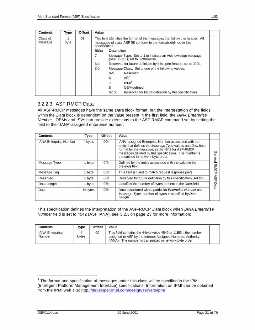
03h This field identifies the format of the messages that follow this header. All messages of class ASF (6) conform to the formats defined in this specification. Bit(s) Description 7 Message Type. Set to 1 to indicate an Acknowledge message
(see 3.2.2.1); set to 0 otherwise. 6:4 Reserved for future definition by this specification, set to 000b. 3:0 Message Class. Set to one of the following values: 0-5 Reserved 6 ASF
7 IPMI1 8 OEM-defined 9-15 Reserved for future definition by this specification.
3.2.2.3 ASF RMCP Data All ASF-RMCP messages have the same Data block format, but the interpretation of the fields within the Data block is dependent on the value present in the first field: the IANA Enterprise Number. OEMs and ISVs can provide extensions to the ASF-RMCP command set by setting the field to their IANA-assigned enterprise number.
Contents Type Offset Value
IANA Enterprise Number 4 bytes 00h IANA-assigned Enterprise Number associated with the entity that defines the Message Type values and Data field format for the message; set to 4542 for ASF-RMCP messages defined by this specification. The number is transmitted in network byte order.
Message Type 1 byte 04h Defined by the entity associated with the value in the previous field.
Message Tag 1 byte 05h This field is used to match request-response pairs.
Reserved 1 byte 06h Reserved for future definition by this specification, set to 0.
Data Length 1 byte 07h Identifies the number of bytes present in the Data field
Data N bytes 08h Data associated with a particular Enterprise Number and Message Type, number of bytes is specified by Data Length.
General R
MC
P A
SF D
ata
This specification defines the interpretation of the ASF-RMCP Data block when IANA Enterprise Number field is set to 4542 (ASF IANA), see 3.2.3 on page 23 for more information:
Contents Type Offset Value
IANA Enterprise Number
4 bytes
00 This field contains the 4-byte value 4542 or 11BEh, the number assigned to ASF by the Internet Assigned Numbers Authority (IANA). The number is transmitted in network byte order.
1 The format and specification of messages under this class will be specified in the IPMI (Intelligent Platform Management Interface) specifications. Information on IPMI can be obtained from the IPMI web site: http://developer.intel.com/design/servers/ipmi

Alert Standard Format (ASF) Specification 1.03
DSP0114.doc 20 June 2001 Page 22 of 79
Contents Type Offset Value
Message Type 1 byte 04h 00h:0Fh Reserved 10h:3Fh ”Set” commands 10h Reset, see page 23 11h Power-up, see page 23 12h Unconditional Power-down, see page 25 13h Power Cycle Reset, see page 23 40h:7Fh Response or “Get Response” commands 40h Presence Pong, see page 26 41h Capabilities Response, see page 26 42h System State Response, see page 27 80h:BFh Request or “Get” commands 80h Presence Ping 81h Capabilities Request 82h System State Request All other values are reserved for future definition by this specification.
Message Tag 1 byte 05h This 1-byte field is used to match request-response pairs. This value is copied into the response message when one is generated in a request-response interaction, e.g. the Presence Ping/Presence Pong pair. When a duplicate message is received, i.e. one with the same Message Tag, the consumer of the message determines whether the message is accepted or rejected. For example, an alert-sending device might be designed to respond to all Presence Ping messages received, or to keep track of recent Presence Ping messages and only respond to those with unique Message Tag values. See below for more information. Note: A value of 255 (FFh) indicates that the associated message is not a request-response type message.
Reserved 1 byte 06h Reserved for f uture definition by this specification, set to 0.
Data Length 1 byte 07h This 1-byte field contains the byte length of the message’s variable-length Data field.
Data N bytes
08h Data associated with a particular Message Type, number of bytes is specif ied by Data Length.
Standard R
MC
P A
SF D
ata
Using the Message Tag Field Many of the ASF-RMCP messages are of the request/response type:
• A Presence Ping sent from a management console requests that the client respond with a Presence Pong
• A Capabilities Request from a management console requests that the client respond with a Capabilities Response
• A System State Request from a management console requests that the client respond with a System State Response.
For each of these message pairs, the ASF-RMCP Data block’s Message Tag field provides a method to bind a response to its associated request. For example, a management console sends a Presence Ping with the Message Tag field set to 12h to a managed client. The client’s alert-sending device copies the Message Tag field value from the message received into the associated Presence Pong response prior to transmitting that message. When the management console receives the Presence Pong, the console can quickly map the message to its associated Presence Ping by matching the Message Tag fields.

Alert Standard Format (ASF) Specification 1.03
DSP0114.doc 20 June 2001 Page 23 of 79
3.2.3 ASF RMCP Message Types This section defines message data formats for the standard RMCP “ASF” class, i.e. the IANA Enterprise Number in the RMCP Data section is 4542. This specification defines the Data portion of each message; OEMs and ISVs can provide extensions using the general RMCP “ASF” class, but cannot extend the standard messages’ packet size.
3.2.3.1 Reset (10h), Power-up (11h), and Power Cycle Reset (13h) The management console can send messages to cause the managed client to perform a hard-reset, power up, or power cycle reset. See section 6.3.3 for detailed descriptions and definitions of these remote control functions. Each of these message types can optionally include Boot Options in its variable data; the options define operations the managed client performs with the boot initiated by the ASF-RMCP message. The RMCP packet’s Data Length value indicates the presence (0Bh or greater) or absence (00h) of the options. The Boot Options contain a bit-mask of standard options and a Special Command with an optional parameter.
If the managed client doesn’t support the message (as indicated on the presumed, previous response to the console’s Capabilities Request message), the alert-sending device issues an RMCP Acknowledge and otherwise disregards the message. Any message disregarded in this fashion has no effect on the alert-sending device’s response to a subsequently issued SMBus Get Boot Options message (see 5.2 for these messages’ definitions). Otherwise, the alert -sending device records the Boot Options and Special Command values and reports those values in response to subsequently issued SMBus Get Boot Options messages until either 1. The alert-sending device receives another RMCP message, supported by the system. This
message’s Boot Options and Special Command values replace the previously recorded values.
2. The alert-sending device receives an SMBus Boot Options Clear message (see 5.2.2 for details). Until the alert-sending device receives another RMCP message with Boot Options values, the device responds with the No Boot Options response to any SMBus Get Boot Options messages.
When the Boot Options are present, the message’s Data field is organized as follows:
Boot Options
Data Byte
Field Description
1-4 IANA Enterprise Number
IANA-assigned Enterprise Number — ASF (4542) or OEM specific — that defines the interpretation of the OEM Special Command values and their associated Special Command Parameters, and the OEM Parameters fields. Note: This specification defines the interpretation of the Boot Options Bit Mask field, regardless of the Enterprise Number value.
5 Special Command Defines commands to be processed by the managed client on the boot initiated by the ASF-RMCP message. See Special Command Definitions below for more detail.
6-7 Special Command Parameter
Defines a command parameter to augment the Special Command. See Special Command Definitions below for more detail. Parameter byte 1 is present in Data Byte 6; parameter byte 2 is present in Data Byte 7.
8-9 Boot Options Bit Mask
Defines a standard set of firmware operations. See Boot Options Bit Mask below for more detail. Boot Options Bit Mask Byte 1 is present in Data Byte 8, Boot Options Bit Mask Byte 2 is present in Data Byte 9, and so on.

Alert Standard Format (ASF) Specification 1.03
DSP0114.doc 20 June 2001 Page 24 of 79
Boot Options
Data Byte
Field Description
10-11 OEM Parameters Defines parameters that further augment the Special Command definition; the entity associated with the Enterprise Number defines the interpretation of these fields. These fields have no meaning when the Enterprise Number is 4542 (ASF).
Special Command Definitions ASF defines the following Special Command values, present as byte 5 of the Boot Options; the meaning applies only when the IANA Enterprise Number specified in the Boot Options is the value 4542 (ASF).
Value Description
00h NOP. No additional special command is included; the Special Command Parameter has no meaning.
01h Force PXE Boot. The Special Command Parameter can be used to specify a PXE parameter. When the parameter value is 0, the system default PXE device is booted. All other values for the PXE parameter are reserved for future definition by this specification.
02h Force Hard-drive Boot. The Special Command Parameter identifies the boot-media index for the managed client. When the parameter value is 0, the default hard-drive is booted, when the parameter value is 1, the primary hard-drive is booted; when the value is 2, the secondary hard-drive is booted – and so on.
03h Force Hard-drive Safe Mode Boot. The Special Command Parameter identifies the boot-media index for the managed client. When the parameter value is 0, the default hard-drive is booted, when the parameter value is 1, the primary hard-drive is booted; when the value is 2, the secondary hard-drive is booted – and so on.
04h Force Diagnostic Boot. The Special Command Parameter can be used to specify a diagnostic parameter. When the parameter value is 0, the default diagnostic media is booted. All other values for the diagnostic parameter are reserved for future definition by this specification.
05h Force CD/DVD Boot. The Special Command Parameter identifies the boot-media index for the managed client. When the parameter value is 0, the default CD/DVD is booted, when the parameter value is 1, the primary CD/DVD is booted; when the value is 2, the secondary CD/DVD is booted – and so on.
06h to 0BFh
Reserved for future definition by this specification.
0C0h to 0FFh
OEM command values; the interpretation of the Special Command and associated Special Command Parameters is defined by the entity associated with the Enterprise ID.
Boot Options Bit Mask
The following table identifies the bits in the Boot Options Bit Mask, present in the Boot Options as Data Bytes 8 through 11.
Boot Options
Data Byte
Boot Options Bit Mask Byte
Bit Number
Boot Options Bit Mask Description
8 1 7 Reserved, set to 0b.
6 Lock Sleep Button. When set to 1b, the managed client’s firmware disables the sleep button operation for the system, normally until the next boot cycle. Client instrumentation might provide the capability to re-enable the button functionality without rebooting.

Alert Standard Format (ASF) Specification 1.03
DSP0114.doc 20 June 2001 Page 25 of 79
Boot Options
Data Byte
Boot Options Bit Mask Byte
Bit Number
Boot Options Bit Mask Description
5 Lock Keyboard. When set to 1b, the managed client’s firmware disallows keyboard activity during its boot process. Client instrumentation or OS drivers might provide the capability to re-enable the keyboard functionality without rebooting.
4:3 Reserved, set to 00b.
2 Lock Reset Buttons. When set to 1b, the managed client’s firmware disables the reset button operation for the system, normally until the next boot cycle. Client instrumentation might provide the capability to re-enable the button functionality without rebooting.
1 Lock Power Button. When set to 1b, the managed client’s firmware disables the power button operation for the system, normally until the next boot cycle. Client instrumentation might provide the capability to re-enable the button functionality without rebooting.
0 Reserved, set to 0b.
9 2 7 Configuration Data Reset. When set to 1b, the managed client’s firmware resets its non-volatile configuration data to the client’s Setup defaults prior to booting the client.
6:5 Firmware Verbosity. When set to a non-zero value, controls the amount of information the managed client writes to its local display: 00b System default 01b Quiet, minimal screen activity 10b Verbose, all messages appear on the screen 11b Screen blank, no messages appear on the screen.
4 Force Progress Events. When set to 1b, the managed client’s firmware transmits all progress PET events to the alert-sending device. This option is usually used to aid in fail-to-boot problem determination.
3 User Password Bypass. When set to 1b, the managed client’s firmware boots the system and bypasses any user or boot password that might be set in the system. This option allows a system administrator to, for example, force a system boot via PXE in an unattended manner.
2:0 Reserved, set to 000b.
3.2.3.2 Unconditional Power-Down (12h) The management console sends this RMCP message to the managed client to cause the client to perform an unconditional power-down. See section 6.3.3 for a detailed description and definition of this remote control function. Data Length for the sent message is set to 00h, no additional data is sent.
Note: Since this message does not result in an ASF-RMCP-initiated managed client boot, no Boot Options specification is supported.

Alert Standard Format (ASF) Specification 1.03
DSP0114.doc 20 June 2001 Page 26 of 79
3.2.3.3 Presence Pong (40h) An ASF managed client sends this message — in response to a management console’s Presence Ping (80h) RMCP message — to identify the presence of an ASF-RMCP-aware managed client on the network. The Message Tag value of the Presence Ping’s RMCP Header is copied to this message’s Message Tag field. The format of this message’s Data section is as follows:
Data Byte(s)
Field Description
1-4 IANA Enterprise Number2
If no OEM-specific capabilities exist, this field contains the ASF IANA (4542) and the OEM-defined field is set to all zeroes (00000000h). Otherwise, this field contains the OEM’s IANA Enterprise Number and the OEM-defined field contains the OEM-specific capabilities. Note: Regardless of the value in the IANA Enterprise Number, this specification defines the interpretation of data bytes 9 and higher.
5-8 OEM-defined2 OEM defined fields.
9 Supported entities
Bit(s) Value/Meaning 7 Set to 1 if IPMI is supported. 6:4 Reserved for future definition by this specification, set to 000b. 3:0 0000b Reserved 0001b ASF, Version 1.0 Others Reserved for future definition by this specification.
10 Supported interactions
Bit(s) Value/Meaning 7:0 Reserved for future definition by this specification, set to
00000000b
11-16 Reserved Reserved for future definition by this specification, set to all zeros.
3.2.3.4 Capabilities Response (41h) An ASF managed client sends this message — in response to a management console’s Capabilities Request (81h) RMCP message — to describe the client system's ASF capabilities. The Message Tag value of the Capability Request’s RMCP Header is copied to this message’s Message Tag field. The capabilities described are the least common denominator of the capabilities of the alert-sending device, the motherboard, the firmware, and the supporting software. This message’s Data section is formatted as follows:
Data Byte(s)
Field Description
1-4 IANA Enterprise Number2
If no OEM-specific capabilities exist, this field contains the ASF IANA (4542) and the OEM-defined field is set to all zeroes (00000000h). Otherwise, this field contains the OEM’s IANA Enterprise Number and the OEM-defined field contains the OEM-specific capabilities. Note: Regardless of the value in the IANA Enterprise Number, this specification defines the interpretation of data bytes 9 and higher.
5-8 OEM defined2 OEM defined fields.
9-10 Special Commands Supported
Defines the standard set of ASF-RMCP Special Commands supported by the managed client. See Special Commands Bit Mask for detailed information.
11 System Capabilities Supported
Defines the standard set of system capabilities supported by the managed client system. See System Capabilities Bit Mask for detailed information.
2 This field can contain OEM-defined values; the method through which these values are communicated to an alert-sending device is left to the device manufacturer.

Alert Standard Format (ASF) Specification 1.03
DSP0114.doc 20 June 2001 Page 27 of 79
Data Byte(s)
Field Description
12-15 System Firmware Capabilities Supported
Defines the standard set of firmware capabilities supported by the managed client. See System Firmware Capabilities Bit Mask for detailed information.
16 Reserved Reserved for future definition by this specification; set to 0
Special Commands Bit Mask The following table describes the special commands bit mask.
Response Data Byte
Bit Mask Byte
Bit(s) Meaning
9 1 7:0 Reserved to identify support for ASF-RMCP Special Commands defined by a future version of this specification, set to 00h.
10 2 7:5 Reserved to identify support for ASF-RMCP Special Commands defined by a future version of this specification, set to 000b.
4 Supports Force CD/DVD Boot command, if set to 1b.3
3 Supports Force Diagnostic Boot command, if set to 1b. 3
2 Supports Force Hard-drive Safe-mode Boot command, if set to 1b. 3
1 Supports Force Hard-drive Boot command, if set to 1b. 3
0 Supports Force PXE Boot command, if set to 1b.
System Capabilities Bit Mask The following table describes the system capabilities bit mask.
Response Data Byte
Bit Mask Byte
Bit(s) Meaning
11 1 7 Supports Reset, if 1b
6 Supports Power-Up, if 1b
5 Supports Power-Down, if 1b
4 Supports Power Cycle Reset, if 1b
3:0 Reserved for future assignment by this specification, set to 0000b.
System Firmware Capabilities Bit Mask These bit-flags identify the remote-control features supported by the system firmware. These bits are very similar to the Boot Options bit mask in the RMCP boot-related messages; see 3.2.3.1. They are slightly different because this format uses a capability bit for each encoding in the RMCP command to identify individual option support. Note: These capabilities reflect the RMCP support provided by the managed client (as identified via its ACPI implementation, see 4.1.2.6 ASF_RMCP), and its alert-sending device.
Response Data Byte
Bit Mask Byte
Bit(s) Meaning
12 1 7 Reserved for future assignment by this specification, set to 0b.
6 Supports Sleep Button Lock, if 1b
5 Supports Lock Keyboard, if 1b
4:3 Reserved for future assignment by this specification, set to 00b.
3 Many of these choices are outside the realm of the managed client’s firmware and require support from either the OS or boot-manager to accomplish.

Alert Standard Format (ASF) Specification 1.03
DSP0114.doc 20 June 2001 Page 28 of 79
Response Data Byte
Bit Mask Byte
Bit(s) Meaning
2 Supports Reset Button Lock, if 1b
1 Supports Power Button Lock, if 1b
0 Supports Firmware Verbosity/Screen Blank, if 1b
13 2 7 Supports Configuration Data Reset, if 1b
6 Supports Firmware Verbosity/Quiet, if 1b
5 Supports Firmware Verbosity/Verbose, if 1b
4 Supports Forced Progress Events, if 1b
3 Supports User Password Bypass, if 1b
2:0 Reserved for future assignment by this specification, set to 000b.
14 3 7:0 Reserved for future assignment by this specification, set to 00h.
15 4 7:0 Reserved for future assignment by this specification, set to 00h.
3.2.3.5 System State Response (42h) An ASF managed client sends this message — in response to a management console’s System State Request (82h) RMCP message — to identify the state of the managed client. The Message Tag value of the System State Request’s RMCP Header is copied to this message’s Message Tag field. The format of the message’s Data section is as follows:
Data Bytes
Field Description
1 System State4 Bit(s) Value/Meaning 7:4 Reserved for future definition, set to 000b. 3:0 0000b S0 / G0 “working” 0001b S1 “sleeping with system h/w & processor context maintained” 0010b S2 “sleeping, processor context lost” 0011b S3 “sleeping, processor & h/w context lost, memory retained.” 0100b S4 “non-volatile sleep / suspend-to disk” 0101b S5 / G2 “soft-off” 0110b S4 / S5 soft-off, particular S4/S5 state cannot be determined 0111b5 G3 / Mechanical Of f 1000b Sleeping in an S1, S2, or S3 states (used when particular
S1, S2, S3 state cannot be determined), or Legacy SLEEP state.
1001b G1 sleeping (S1-S4 state cannot be determined) 1010b5 S5 entered by override (e.g. 4-second power button override) 1011b Legacy ON state (e.g. non-ACPI OS working state) 1100b Legacy OFF state (e.g. non-ACPI OS off state) 1110b Unknown 1111b Reserved for future definition
4 In some implementations, the system state reported by the alert-sending device may be a “best guess” or a “last known” reporting mechanism, because the managed client’s firmware might not be able to program the system state for various reasons. For example, it is conceivable that the state was entered by hardware and software did not have a chance to program the state information, or software pre-programs the system state, but the next state was not reached. 5 This state might not be reported either because (a) a software entity (e.g. BIOS) is responsible for programming the device and the state is initiated by hardware, or (b) the hardware is not powered in the state and incapable of responding.

Alert Standard Format (ASF) Specification 1.03
DSP0114.doc 20 June 2001 Page 29 of 79
Data Bytes
Field Description
2 Watchdog State
Bit(s) Value/Meaning 7:1 Reserved for future definition by this specification, set to 0000000b 0 WDE (Watchdog Timer Expired) 1b = Indicates that the ASF alert-sending device’s Watchdog Timer
has expired and has not been stopped by a Stop Watchdog Timer command.
0b = Indicates that the ASF alert-sending device’s Watchdog Timer is currently not expired because (a) it has not yet been started since power-on reset, (b) it has been started and is running but not expired yet, or (c) it has been stopped.
This bit becomes set when the Watchdog Timer expires after a Start Watchdog Timer command is issued and the timer expires. Subsequent Start Watchdog Timer or Stop Watchdog Timer commands or an alert-sending device power-on reset will clear this status to 0b.
3-4 Reserved Reserved for future definition by this specification, set to 0000h.
3.2.3.6 Presence Ping (80h) The ASF-aware management console sends this RMCP message to the managed client to request a client to respond with a Presence Pong (40h) message — if the client so responds, it signifies that it is also ASF-aware. Data Length for the sent message is set to 00h, no additional data is sent.
3.2.3.7 Capabilities Request (81h) The management console sends this RMCP message to the managed client to request the client to respond with a Capabilities Response (41h) message. Data Length for the sent message is set to 00h, no additional data is sent.
3.2.3.8 System State Request (82h) The management console sends this RMCP message to the managed client to request the client to respond with a System State Response (42h) message. Data Length for the sent message is set to 00h, no additional data is sent.

Alert Standard Format (ASF) Specification 1.03
DSP0114.doc 20 June 2001 Page 30 of 79
3.2.4 RMCP Usage Scenarios The following flowchart describes the process used by the RMCP command initiator, e.g. the management console for the Capabilities Request message, to determine whether a response to a previously sent message was received.
Y
Send Message
Increment Sequence Number
Start ACK Timer
N
ACK Rcvd?
N
Start RSP Timer
N
N
Y
Y
Timer Expire?
Timer Expire?
Retry?
Y
Y Retry?
Message Complete
Error, no ACK
N
Error, no RSP
N
Y RSP Rcvd?
Interactions with no packet loss The description that follows illustrates the RMCP Header and RMCP Data fields in a console-to-client communication where no messages are lost. 1. The management console sends an ASF-RMCP “Request” message
RMCP Header ASF-RMCP Data
Vers Rsvd Seq# Class IANA Enterprise Number Type Tag Rsvd Len
06h 00h 05h 06h 00h 00h 11h BEh xx 08h xx xx

Alert Standard Format (ASF) Specification 1.03
DSP0114.doc 20 June 2001 Page 31 of 79
2. The managed client responds with an RMCP ACK, returning only an RMCP Header. Note that all values are copied from the “Request” message’s RMCP header, with the “ACK” bit set in the fourth byte.
RMCP Header
Vers Rsvd Seq# Class
06h 00h 05h 86h
3. The managed client responds with the associated ASF-RMCP “Response”. Note that the Message Tag value (08h) is copied from the “Request” message.
RMCP Header ASF-RMCP Data
Vers Rsvd Seq# Class IANA Enterprise Number Type Tag Rsvd Len
06h 00h 09h 06h 00h 00h 11h BEh xx 08h xx xx
4. The management console, having received both the ACK and “Response” sends an RMCP ACK, completing the request/response cycle. The RMCP Header is copied from the managed client’s “Response” message, with the “ACK” bit set in byte 4.
RMCP Header
Vers Rsvd Seq# Class
06h 00h 09h 86h
Interactions with some packet loss 1. The description that follows illustrates the RMCP Header and RMCP Data fields in a console-
to-client communication where some of the messages are lostThe management console sends an ASF-RMCP “Request” message
RMCP Header ASF-RMCP Data
Vers Rsvd Seq# Class IANA Enterprise Number Type Tag Rsvd Len
06h 00h 05h 06h 00h 00h 11h BEh xx 08h xx xx
2. The management console waits to receive an ACK from the client, but the client never received that “Request” message; the console re-transmits the “Request” message with the same Sequence Number as the original message in step 1.
RMCP Header ASF-RMCP Data
Vers Rsvd Seq# Class IANA Enterprise Number Type Tag Rsvd Len
06h 00h 05h 06h 00h 00h 11h BEh xx 08h xx xx
3. The managed client responds with an RMCP ACK, returning only an RMCP Header. Note that all values are copied from the “Request” message’s RMCP header, with the “ACK” bit set in the fourth byte. The console never receives this ACK.
RMCP Header
Vers Rsvd Seq# Class
06h 00h 05h 86h
4. The managed client responds with the associated ASF-RMCP “Response”. Note that the Message Tag value (08h) is copied from the “Request” message.
RMCP Header ASF-RMCP Data
Vers Rsvd Seq# Class IANA Enterprise Number Type Tag Rsvd Len
06h 00h 09h 06h 00h 00h 11h BEh xx 08h xx xx

Alert Standard Format (ASF) Specification 1.03
DSP0114.doc 20 June 2001 Page 32 of 79
5. The management console waits to receive an ACK from the client, but the ACK is lost; the console (again) re-transmits the “Request” message with the same Sequence Number as the original message in step 1.
RMCP Header ASF-RMCP Data
Vers Rsvd Seq# Class IANA Enterprise Number Type Tag Rsvd Len
06h 00h 05h 06h 00h 00h 11h BEh xx 08h xx xx
6. The managed client responds with an RMCP ACK, returning only an RMCP Header. Note that all values are copied from the “Request” message’s RMCP header, with the “ACK” bit set in the fourth byte.
RMCP Header
Vers Rsvd Seq# Class
06h 00h 05h 86h
7. The managed client responds with the associated ASF-RMCP “Response”, possibly with a new Sequence Number. Note that the Message Tag value (08h) is copied from the “Request” message.
RMCP Header ASF-RMCP Data
Vers Rsvd Seq# Class IANA Enterprise Number Type Tag Rsvd Len
06h 00h 0Ah 06h 00h 00h 11h BEh xx 08h xx xx
8. The management console receives the ACK and waits for the “Response” from the client, but the “Response” is lost; the console (again) re-transmits the “Request” message with the same Sequence Number as the original message in step 1.
RMCP Header ASF-RMCP Data
Vers Rsvd Seq# Class IANA Enterprise Number Type Tag Rsvd Len
06h 00h 05h 06h 00h 00h 11h BEh xx 08h xx xx
9. The managed client responds with an RMCP ACK, returning only an RMCP Header. Note that all values are copied from the “Request” message’s RMCP header, with the “ACK” bit set in the fourth byte.
RMCP Header
Vers Rsvd Seq# Class
06h 00h 05h 86h
10. The managed client responds with the associated ASF-RMCP “Response”, possibly with a new Sequence Number. Note that the Message Tag value (08h) is copied from the “Request” message.
RMCP Header ASF-RMCP Data
Vers Rsvd Seq# Class IANA Enterprise Number Type Tag Rsvd Len
06h 00h 0Bh 06h 00h 00h 11h BEh xx 08h xx xx
11. The management console, having received both the ACK and “Response” sends an RMCP ACK, completing the request/response cycle. The RMCP Header is copied from the managed client’s “Response” message, with the “ACK” bit set in byte 4.
RMCP Header
Vers Rsvd Seq# Class
06h 00h 0Bh 86h

Alert Standard Format (ASF) Specification 1.03
DSP0114.doc 20 June 2001 Page 33 of 79
3.2.5 RMCP Considerations for LAN Alert-sending Devices For the RMCP protocol to function in an OS-absent state, the alert-sending device must be capable of reporting its “network address / IP address” association to the local router. The ARP (Address Resolution Protocol), defined in [RFC1188], is typically used to accomplish this task. To guarantee inter-operability, the alert-sending device must:
• Receive ARP Requests and reply with ARP Replies in an OS-absent state.
• Allow ARP Request packets to go to the network software stack in OS-present states.
• Allow ARP Request packets and RMCP packets to cause wake-ups if configured for wake-up in the default configuration.
For Ethernet and Token-ring devices, wake-ups from ARP Requests and RMCP packets are not desired in a managed client because these operations are expected to function in low power sleep states. However, the [NDCPM] requires that wake-up devices support detection of any software programmed packets as well as subsequent wake-up generation. Alert-sending devices that support wake-up generation are expected to meet the [NDCPM] in their default configuration. However, it is recommended that these alert-sending devices and their software provide configuration mechanisms to allow ARP Request and RMCP packets to be blocked from wake-up. Note: ARP Request packets and IP Directed packets (which include RMCP packets) are standard packet configurations for wake-up in ACPI systems.

Alert Standard Format (ASF) Specification 1.03
DSP0114.doc 20 June 2001 Page 34 of 79
4 Firmware Interfaces
A managed client’s ASF configuration and capabilities are reported by the system firmware (or BIOS) via ACPI description tables and control methods and, optionally, as static information stored within an SEEPROM. OS-present software uses this information to customize the system’s ASF-aware alert-sending device(s).
An ASF-enabled system firmware provides: 1. An ACPI description table that identifies
• If present, undiscoverable fixed-address sensor devices in the system and their characteristics
• The system’s ASF capabilities, and system type for use in the Platform Event Trap messages
• Any legacy sensor-access information, if present in the system.
• Any remote-control actions supported by the system hardware, and the associated device information.
• The system’s (optional) support for RMCP, and the last RMCP command completed by the system firmware.
2. ACPI Control Methods that identify
• The methods that provide configuration of the system’s (optional) OS Boot Hang watchdog timer.
3. SMBIOS structures that identify
• The UUID/GUID for use in the Platform Event Trap messages A managed client might also provide SEEPROM devices that duplicate the static information provided by the ACPI description table.
4.1 ACPI Definitions System firmware identifies the system’s ASF support and configuration requirements via ACPI interfaces.
4.1.1 Control Methods An ASF managed client’s firmware uses ACPI control methods (required elements are marked in bold) to provide OS-present access to ASF configuration information that is dynamically updateable:
Device(ASF) { Name(_HID, “ASF0001”) // Hardware ID (PnP ID)
Method(GPWT, 0) {…} // ASF Get Power-on Wait Time Method(SPWT, 1) {…} // ASF Set Power-on Wait Time }
ASF-defined object names must follow the ASL naming convention defined in section 16.1.2 of [ACPI]. The recommended format for specifying the name of the ASF object is Device (ASF) The ASF object utilizes the _HID device identification object, providing ‘automatic’ enumeration by the ACPI-aware operating system: Name(_HID, “ASF0001”)
Used to specify the Plug and Play hardware ID for the ASF object

Alert Standard Format (ASF) Specification 1.03
DSP0114.doc 20 June 2001 Page 35 of 79
Notes: 1. If the managed client supports an OS Boot Failure alert (see 3.1.5.4), the system’s ACPI
implementation includes a Metolious [MTLS] System Hang Watchdog device of type “OS Boot Failure”. The control methods associated with that watchdog device provide the OS-present methods through which the watchdog’s configuration can be controlled. If multiple alerting devices are present in the system, all devices’ watchdog timers are configured in an identical manner by the system firmware prior to the firmware’s attempt to boot the operating system.
4.1.1.1 Get Power-on Wait Time (GPWT) Description: Returns the current value of the system’s power-on wait time, in seconds.
Input Argument(s):
<none>
Output Argument(s):
Power-on Wait Time (Integer)
The current system power-on wait time, in seconds.
Notes: The system firmware has a single, maximum amount of time that it might wait for an ASF alert-sending device to establish connection with its transport media. For example, an Ethernet device might require additional time from a cold power-on to establish a network connection. Since there might be multiple ASF alert-sending devices in the system, a device’s configuration software should first get the current wait time and set a new time only if the device requires more time. See 5.1.5 for more information.
4.1.1.2 Set Power-on Wait Time (SPWT) Description: Sets the system’s power-on wait time, in seconds.
Input Argument(s):
Power-on Wait Time (Integer)
The value, in seconds, that an ASF alert-sending device requires to establish connection with its transport media.
Output Argument(s):
<none>
Notes: The system firmware has a single, maximum amount of time that it might wait for an ASF alert-sending device to establish connection with its transport media. For example, an Ethernet device might require additional time from a cold power-on to establish a network connection. Since there might be multiple ASF alert-sending devices in the system, a device’s configuration software should first get the current wait time and set a new time only if the device requires more time. See 5.1.5 for more information.
4.1.2 ASF! Description Table System firmware identifies the system’s ASF support and static configuration using the ACPI System Description Table architecture. A pointer to the ASF-defined ASF! description table appears as one of the entries in the firmware’s RSDT (for IA-32 systems) or XSDT (for IA-64 systems). The information presented in this table is static from the reference of the client’s last boot.
This table is formatted as a standard ACPI System Description Table Header followed by one or more ASF information records. An information record contains a chained header and its associated data as follows:
Field Byte Length
Byte Offset
Description

Alert Standard Format (ASF) Specification 1.03
DSP0114.doc 20 June 2001 Page 36 of 79
Field Byte Length
Byte Offset
Description
Type 1 0 This field identifies the type of data present in the record’s Variable Data field, as well as an indication as to whether this is the last record in the table: Bit(s) Description 7 Last Record. If this bit is set to 1b, then the record is the
last one present in the ASF! table. 6:0 Record Type. Identifies the format of the record’s Variable
Data field, one of: 00h ASF_INFO. See section 4.1.2.1. 01h ASF_ALRT. See section 4.1.2.2. 02h ASF_RCTL. See section 4.1.2.4. 03h ASF_RMCP. See section 4.1.2.6. 04h ASF_ADDR. See section 4.1.2.7. 05h-7Fh Reserved for future definition by this specification
Reserved 1 1 Reserved for future definition by this specification, set to 00h.
Record Length
2 2 Identifies the length of the information record, starting at offset 0.
Variable Data
Varies 4 Contains the data specified by the Type field.
Notes:
1. Record Type values of 00h are required for a managed client’s ASF configuration. 2. The consumer of this information should make no assumption regarding the order in which
the records are specified, i.e. a Record Type of 02h could appear in the table prior to a Record Type of 00h.
Field Byte Length
Byte Offset
Description
ACPI System Description Table Header
Signature 4 0 ‘ASF!’. Signature for the ASF Description Table.
Length 4 4 The length of the table, in bytes, starting at offset 0.
Revision 1 8 The revision of the structure, and the version of the ASF specification supported by the system. The value is stored as a BCD (binary coded decimal) value. For ASF version 1.0, the value is 10h.
Checksum 1 9 The entire table, including the checksum field, must sum to zero to be considered valid by the information consumer.
OEMID 6 10 An OEM-supplied string that identifies the OEM.
OEM Table ID 8 16 For this table, the value is the manufacturer model ID.
OEM Revision
4 24 An OEM-supplied revision number of this table. Larger numbers are assumed to be newer revisions.
Creator ID 4 28 Vendor ID of the utility that created this table. For tables containing Definition Blocks, this is the ID for the ASL Compiler.
Creator Revision
4 32 Revision of the utility that created the table. For tables containing Definition Blocks, this is the revision for the ASL Compiler.
ASF-specified data fields
Information Record #1
Varies 36 Contains the first (or only) ASF Information record for the managed client’s implementation.
…

Alert Standard Format (ASF) Specification 1.03
DSP0114.doc 20 June 2001 Page 37 of 79
Field Byte Length
Byte Offset
Description
Information Record #n
Varies Varies Contains the last ASF Information Record for the managed client’s implementation, with the Last Record bit of the Type field set to 1b.
4.1.2.1 ASF_INFO This structure contains information that identifies the system’s type and configuration requirements for ASF alerts, and is associated with an ASF Information Record Header of the following format:
Type = 00h or 80h
Reserved = 00h
Length = 0010h (16) for ASF v1.0. The length might increase for future specification versions.
Offset Name Length Value Description
00h Minimum Watchdog Reset Value
BYTE Varies Identifies the minimum value (in the range 1 to 256) to which an alert-sending device’s watchdog timer should be set at power-on reset, in seconds. This value also reflects the maximum amount of time the system firmware requires to reset the initial system boot-failure watchdog timer.
01h Minimum ASF Sensor Inter-poll Wait Time
BYTE Varies Identifies the minimum time, in 5 millisecond units, that an alert sending device should wait between the end of one ASF Sensor Poll Alert Message to the start of the next. The value ranges from 2 to 255. See below for more information.
02h System ID WORD Varies Contains the manufacturer-assigned ID for this system type. Each Platform Event Trap issued by a managed client’s alert-sending device(s) will contain this value in its System ID field.
04h IANA Manufacturer ID
4 BYTEs Varies Contains the Private Enterprise Number assigned to the system manufacturer by the Internet Assigned Numbers Authority (IANA). Refer to the Enterprise Numbers section found at http://www.iana.org/numbers.html#E for current assignments. Each Platform Event Trap issued by a managed client’s alert-sending device(s) will contain this value in its Manufacturer ID field. Note: The value is specified in network byte order (MSB first) within the field.
08h Reserved 4 BYTEs 00h, 00h, 00h, 00h
Reserved for future definition by this specification, set to all zeros.

Alert Standard Format (ASF) Specification 1.03
DSP0114.doc 20 June 2001 Page 38 of 79
The following is a ‘C’-style definition of the ASF_INFO structure. struct ASF_INFO { BYTE MinWatchdogResetValue; BYTE MinPollingInterval; WORD SystemID; BYTE IANAManufacturerID[4]; BYTE Reserved[4]; };
Minimum ASF Sensor Inter-poll Wait Time
The system firmware specifies the minimum inter-poll wait time to achieve two goals:
1. to ensure that an alert sending device does not dominate the SMBus
2. to ensure that every sensor in the system is polled within a reasonable time. To achieve these goals the Minimum Inter-poll Wait Time specifies the amount of time, in 5 millisecond units, an alert-sending device must wait between the completion of one event-polling cycle to the start of the next. If the device uses the SMBus Get Event Status message to start its polling cycle, the cycle includes any Get Event Data messages necessary to retrieve event-specific data. If the device uses only SMBus Get Event Data messages, each cycle is limited to a single message. The following diagram illustrates these two conditions.
Get Event Data
Get Event Data
Get Event Data
Get Event Data
ASF Sensor Inter - poll
Time
ASF Sensor Inter - poll
Time
ASF Sensor Inter - poll
Time
Time
Polling with the Get Event Data Message for ASF Sensors
System implementers should set this time so that no one alert-sending device uses more the 25% of the SMBus bandwidth for the Poll Alert Messages, and so that each sensor is polled at least once a second. Following are guidelines for choosing this system-specific value:
Get Event Status
ASF Sensor Inter - poll
Time
ASF Sensor Inter - poll
Time
ASF Sensor Inter - poll
Time
Time
Polling with the Get Event Status Message for ASF Sensors
* The Get Event Status message identifies the status change(s) and the Get Event Data message corresponds to the data associated with the specific status change(s)
Get Event Status
Get Event Status
Get Event Status
Get Event Data
Get Event Data

Alert Standard Format (ASF) Specification 1.03
DSP0114.doc 20 June 2001 Page 39 of 79
• If all the sensors can run at 100KHz without doing any SMBus clock stretching, then the alert-sending device’s poll with alert data for a single sensor will take about 1.2 milliseconds. If the wait time is 10 milliseconds (a field value of 2), then the alert-sending device will use less than 25% of the SMBus bandwidth (about 12%) and 83 sensors can be polled in one (1) second.
• If, on the other hand, the sensors run at the slowest SMBus speed (10KHz) an alert-sending device will require about 12 milliseconds to poll a single sensor. The wait time should be set to 35 milliseconds (a field value of 7) to keep the bandwidth below 25%. This still allows 21 sensors to be polled in one (1) second.
4.1.2.2 ASF_ALRT Legacy sensor devices might be used in a system to provide ASF-compatible alert capabilities. This (optional) data block provides the alert -sending device’s OS-present configuration software with the information needed to poll those devices over the SMBus to determine if an alert-condition has been met. This structure is associated with an ASF Information Record Header of the following format:
Type = 01h or 81h
Reserved = 00h
Length = 4 + 4 + n*m for ASF Version 1.0. Note that this length might increase for future versions of this specification
Offset Name Length Value Description
00h Reserved WORD 0000h Reserved for future definition by this specification, set to 0000h.
02h Number of Alerts (n)
BYTE Varies Identifies the number of m-byte legacy-device alert entries that follow, in the range 1 to 8.
03h Array Element Length (m)
BYTE 0Ch Identifies the size (in bytes) of each Device Array element. For ASF version 1.0 and later, this field is set to a minimum of 0Ch (12).
04h+ m*(n-1)
Device Array Varies Varies An array of m-byte ASF_ALERTDATA structures describing the alert-capable legacy devices present on the system’s SMBus.
The following is a ‘C’-style definition of the ASF_ALRT structure. #define ANYSIZE_ARRAY 1 struct ASF_ALRT { WORD Reserved; BYTE NumberOfAlerts; BYTE ArrayElementLength; struct ASF_ALERTDATA[ANYSIZE_ARRAY]; };
The use of the ANYSIZE_ARRAY is simply for ‘C’ syntactical correctness.
Minimum Legacy Sensor Poll Time
The Minimum Legacy Sensor Poll Time is a fixed value of 4 seconds. Typical Legacy Sensor devices require approximately one second to refresh read data before accessing it again.
This value specifies the amount of time that an alert-sending device must wait between the completion of one series of Legacy Sensor Device Alert Poll Messages and the start of the next. This is shown in the following diagram:

Alert Standard Format (ASF) Specification 1.03
DSP0114.doc 20 June 2001 Page 40 of 79
Poll #1
Legacy Sensor Poll Wait Time
Time
Polling for ASF Legacy Sensor Events
Poll #2
… Poll #8
Poll #1
Poll #2
… Poll #8
4.1.2.3 ASF_ALERTDATA Legacy sensor devices listed in this table must comply with the requirements described in section 6.1. Note: The events described in this data structure by the firmware are always associated with the assertion of a condition. Refer to 6.1.2 Usage of Firmware Legacy Sensor Device Alert Information on page 63 for additional information.
Offset Name Length Value Description
00h Alertn, Device Address (n ranges from 1 to Number of Alerts)
BYTE Varies Contains the SMBus address of a legacy sensor device to which the SMBus command is written, in the following format: Bit(s) Description 7:1 Contains the SMBus address of the legacy
sensor device. 0 Identifies whether (1) or not (0) the alerting
condition (event) is based on an exact match. Refer to 6.1.2 for details.
01h Alertn, Command
BYTE Varies Contains the SMBus Command or register value used to obtain the data associated with the event.
02h Alertn, Data Mask
BYTE Varies The data-mask to be logically AND’d with the returned sensor data to isolate significant bits associated with this event.
03h Alertn, Compare Value
BYTE Varies The value to compare to the masked sensor data, if an exact match is specified in the Device Address field. If a match results, the alert associated with this event should be sent by the alert-sending device.
04h Alertn, Event Sensor Type
BYTE Varies The value to be set6 into the alert’s Event Sensor Type field (see [PET] for definitions.)
05h Alertn, Event Type
BYTE Varies The value to be set6 into the alert’s Event Type field (see [PET] for definitions.)
06h Alertn, Event Offset
BYTE Varies The value to be set6 into the alert’s Event Offset field (see [PET] for definitions.) Note: The value specified here by the system’s firmware always has bit 7 set to 0b to indicate that the alert information is associated with an event assertion.
6 The alert-sending device sets these values into the PET frame it transmits if the associated alerting condition is active.

Alert Standard Format (ASF) Specification 1.03
DSP0114.doc 20 June 2001 Page 41 of 79
Offset Name Length Value Description
07h Alertn, Event Source Type
BYTE Varies The value to be set6 into the alert’s Event Source Type field (see [PET] for definitions.)
08h Alertn, Event Severity
BYTE Varies The value to be set6 into the alert’s Event Severity field (see [PET] for definitions.)
09h Alertn, Sensor Number
BYTE Varies The value to be set6 into the alert’s Sensor Number field (see [PET] for definitions.)
0Ah Alertn, Entity BYTE Varies The value to be set6 into the alert’s Entity field (see [PET] for definitions.)
0Bh Alertn, Entity Instance
BYTE Varies The value to be set6 into the alert’s Entity Instance field (see [PET] for definitions.)
The following is a ‘C’-style definition of the ASF_ALERTDATA structure. struct ASF_ALERTDATA { BYTE DeviceAddress; BYTE Command; BYTE DataMask; BYTE CompareValue; BYTE EventSensorType; BYTE EventType; BYTE EventOffset; BYTE EventSourceType; BYTE EventSeverity; BYTE SensorNumber; BYTE Entity; BYTE EntityInstance; };
4.1.2.4 ASF_RCTL Devices might be used in a system to provide ASF-compatible remote-control system actions. This (optional) information provides an alert-sending device’s OS-present configuration software with the information needed to command those devices to perform remote-control functions over the SMBus. This structure is associated with an ASF Information Record Header of the following format:
Type = 02h or 82h
Reserved = 00h
Length = 4 + 4 + n*m for ASF Version 1.0. Note that this length might increase for future versions of this specification
Offset Name Length Value Description
00h Number of Controls (n)
BYTE Varies Identifies the number of m-byte remote-control entries that follow.
01h Array Element Length (m)
BYTE 05h Identifies the size (in bytes) of each Control Array element. For ASF version 1.0 and later, this field is set to a minimum of 04h (4).
02h Reserved WORD 0000h Reserved for future definition by this specification.
04h + m*(n-1)
Control Array Varies Varies An array of m-byte ASF_CONTROLDATA structures describing the remote-control devices present on the system’s SMBus.

Alert Standard Format (ASF) Specification 1.03
DSP0114.doc 20 June 2001 Page 42 of 79
The following is a ‘C’-style definition of the ASF_RCTL structure. #define ANYSIZE_ARRAY 1 struct ASF_RCTL { BYTE NumberOfAlerts; BYTE ArrayElementLength; struct ASF_CONTROLDATA[ANYSIZE_ARRAY]; };
The use of the ANYSIZE_ARRAY is simply for ‘C’ syntactical correctness.
4.1.2.5 ASF_CONTROLDATA Note: Devices listed in this table must comply with the requirements described in section 6.3.
Offset Name Length Value Description
00h Controln, Function (n ranges from 1 to Number of Controls)
BYTE Varies Identifies the action taken by the system upon issuing the associated SMBus write operation. Refer to section 6.3.3 for more details on the remote control actions. Value Meaning 00h The system performs a reset. 01h The system unconditionally powers off. 02h The system powers on. 03h The system performs a power cycle reset. Other Reserved fur future assignment by this
specification.
01h Controln, Device Address
BYTE Varies Contains the SMBus address to which the SMBus command is written by the alert-sending device. Bit(s) Description 7:1 Contains the SMBus address of the
remote-control device. 0 Identifies whether (1) or not (0) the remote
control command must include a PEC.
02h Controln, Command
BYTE Varies Contains the SMBus Command or register offset to be written with the specified data to perform the specified ASF function.
03h Controln, Data Value
BYTE Varies Contains the data value to be written to the SMBus device to cause the associated function to be performed.
The following is a ‘C’-style definition of the ASF_CONTROLDATA structure. struct ASF_CONTROLDATA { BYTE Function; BYTE DeviceAddress; BYTE Command; BYTE DataValue; };
4.1.2.6 ASF_RMCP This information record’s presence within a managed client’s ACPI implementation implies that the client supports ASF-RMCP remote-control capabilities and captures the RMCP boot options processed by the system firmware on its most recent boot of the system. The firmware provides the captured boot options to allow other system boot agents (e.g. PXE images, hard-disk boot managers) to also make use of the data. Note: An implementation might choose to ignore any RMCP boot options if the system boot cause was other than ASF alert -sending device initiated. In that case, the system firmware reports the boot options as all zeros within this structure.
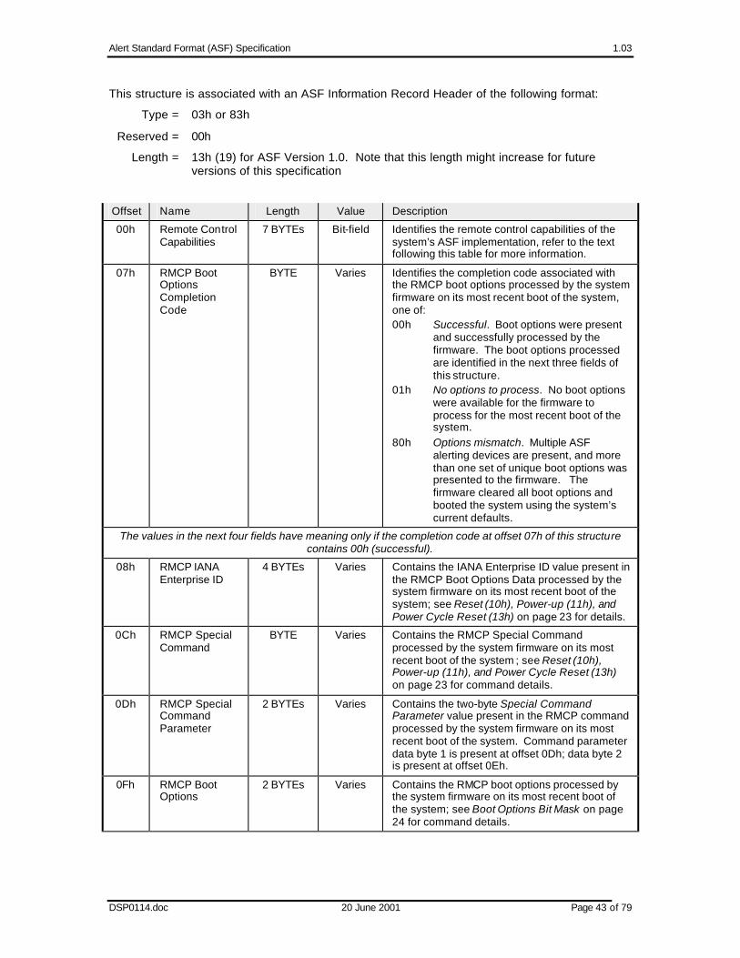
Alert Standard Format (ASF) Specification 1.03
DSP0114.doc 20 June 2001 Page 43 of 79
This structure is associated with an ASF Information Record Header of the following format:
Type = 03h or 83h
Reserved = 00h
Length = 13h (19) for ASF Version 1.0. Note that this length might increase for future versions of this specification
Offset Name Length Value Description
00h Remote Control Capabilities
7 BYTEs Bit-field Identifies the remote control capabilities of the system’s ASF implementation, refer to the text following this table for more information.
07h RMCP Boot Options Completion Code
BYTE Varies Identifies the completion code associated with the RMCP boot options processed by the system firmware on its most recent boot of the system, one of: 00h Successful. Boot options were present
and successfully processed by the firmware. The boot options processed are identified in the next three fields of this structure.
01h No options to process. No boot options were available for the firmware to process for the most recent boot of the system.
80h Options mismatch. Multiple ASF alerting devices are present, and more than one set of unique boot options was presented to the firmware. The firmware cleared all boot options and booted the system using the system’s current defaults.
The values in the next four fields have meaning only if the completion code at offset 07h of this structure contains 00h (successful).
08h RMCP IANA Enterprise ID
4 BYTEs Varies Contains the IANA Enterprise ID value present in the RMCP Boot Options Data processed by the system firmware on its most recent boot of the system; see Reset (10h), Power-up (11h), and Power Cycle Reset (13h) on page 23 for details.
0Ch RMCP Special Command
BYTE Varies Contains the RMCP Special Command processed by the system firmware on its most recent boot of the system ; see Reset (10h), Power-up (11h), and Power Cycle Reset (13h) on page 23 for command details.
0Dh RMCP Special Command Parameter
2 BYTEs Varies Contains the two-byte Special Command Parameter value present in the RMCP command processed by the system firmware on its most recent boot of the system. Command parameter data byte 1 is present at offset 0Dh; data byte 2 is present at offset 0Eh.
0Fh RMCP Boot Options
2 BYTEs Varies Contains the RMCP boot options processed by the system firmware on its most recent boot of the system; see Boot Options Bit Mask on page 24 for command details.
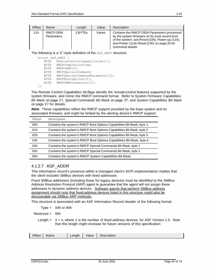
Alert Standard Format (ASF) Specification 1.03
DSP0114.doc 20 June 2001 Page 44 of 79
Offset Name Length Value Description
11h RMCP OEM Parameters
2 BYTEs Varies Contains the RMCP OEM Parameters processed by the system firmware on its most recent boot of the system; see Reset (10h), Power-up (11h), and Power Cycle Reset (13h) on page 23 for command details.
The following is a ‘C’-style definition of the ASF_RMCP structure. struct ASF_RMCP { BYTE RemoteControlCapabilities[7]; BYTE RMCPCompletionCode; BYTE RMCPIANA[4]; BYTE RMCPSpecialCommand; BYTE RMCPSpecialCommandParameter[2]; BYTE RMCPBootOptions[2]; BYTE RMCPOEMParameters[2]; };
The Remote Control Capabilities bit-flags identify the remote-control features supported by the system firmware, and mimic the RMCP command format. Refer to System Firmware Capabilities Bit Mask on page 27, Special Commands Bit Mask on page 27, and System Capabilities Bit Mask on page 27 for details. Note: These capabilities reflect the RMCP support provided by the base system and its associated firmware, and might be limited by the alerting device’s RMCP support.
Offset Description
00h Contains the system’s RMCP Boot Options Capabilities Bit Mask, byte 1.
01h Contains the system’s RMCP Boot Options Capabilities Bit Mask, byte 2
02h Contains the system’s RMCP Boot Options Capabilities Bit Mask, byte 3
03h Contains the system’s RMCP Boot Options Capabilities Bit Mask, byte 4.
04h Contains the system’s RMCP Special Commands Bit Mask, byte 1
05h Contains the system’s RMCP Special Commands Bit Mask, byte 2
06h Contains the system’s RMCP System Capabilities Bit Mask.
4.1.2.7 ASF_ADDR This information record’s presence within a managed client’s ACPI implementation implies that the client includes SMBus devices with fixed addresses. Fixed SMBus addresses (including those for legacy devices) must be identified to the SMBus Address Resolution Protocol (ARP) agent to guarantee that the agent will not assign these addresses to dynamic-address devices. Software agents that perform SMBus address assignment should note that fixed-address devices listed in this structure might also be discoverable via SMBus ARP methods.
This structure is associated with an ASF Information Record Header of the following format:
Type = 04h or 84h
Reserved = 00h
Length = 2 + n, where n is the number of fixed-address devices, for ASF Version 1.0. Note that this length might increase for future versions of this specification
Offset Name Length Value Description

Alert Standard Format (ASF) Specification 1.03
DSP0114.doc 20 June 2001 Page 45 of 79
Offset Name Length Value Description
00h SEEPROM Address
BYTE Varies Identifies the fixed SMBus address of an SEEPROM device that contains additional fixed-address and legacy-device information, as described in SMBus Serial EEPROM. This field is formatted as: Bit(s) Description 7:1 Contains the SMBus address of the SEEPROM
device. 0 Identifies whether (1) or not (0) the SEEPROM
resides on a removable device. Note: If no fixed-address SEEPROM device is supported by the base s ystem, this field is set to 0.
01h Number of Devices (n)
BYTE Varies Identifies the number of device-address entries that follow. Note: If the system supplies the fixed addresses solely via SEEPROM implementation, this field contains 0.
02h Fixed SMBus Address
n BYTEs
Varies Each field contains a fixed SMBus address for the system, in the following format: Bit(s) Description 7:1 Contains the SMBus address of the fixed-address
device. 0 Identifies whether (1b) or not (0b) the address is
associated with a non-legacy, ASF-compliant device. When set to 1b, the SMBus device at this address supports the SMBus 2.0 directed Get UDID command.
The following is a ‘C’-style definition of the ASF_ADDR structure. #define ANYSIZE_ARRAY 1 struct ASF_ADDR { BYTE SEEPROMAddress; BYTE NumberOfDevices; BYTE FixedSMBusAddresses[ANYSIZE_ARRAY]; };
The use of the ANYSIZE_ARRAY is simply for ‘C’ syntactical correctness.
4.2 SMBIOS Structures
4.2.1 System Information (Type 1) The SMBIOS System Information structure contains the system’s UUID (also referred to as the GUID, Globally Unique ID) of the system. An alerting device’s OS-present configuration software records the system’s UUID in the device’s non-volatile storage; any Platform Event Traps issued by the alerting device will then be associated with the system. Refer to [SMBIOS] for this table’s format.
4.3 SMBus Serial EEPROM (SEEPROM) An implementation might choose to identify all or part of the managed client’s fixed SMBus addresses and legacy access-methods using data structures present in an SMBus-attached SEEPROM whose address is specified in the SEEPROM Address field of the ASF_ADDR structure (see 4.1.2.7). This method lends itself to a notebook/docking-station system implementation, with the notebook firmware providing the fixed address of the docking station’s SEEPROM and that SEEPROM providing the fixed addresses present on the docking station itself. Alternatively, the notebook firmware would need to provide the fixed address and legacy-device information for all its supported docking stations.
The SEEPROM referenced by the SEEPROM Address conforms to [FRU], and all ASF-related data are stored in the MultiRecord area of the device.

Alert Standard Format (ASF) Specification 1.03
DSP0114.doc 20 June 2001 Page 46 of 79
4.3.1 Fixed SMBus Addresses (SEEPROM Record Type 06h) A record header of the following format (as defined by [FRU]) identifies a Fixed SMBus Addresses record:
Offset Format Description
00h BYTE Record Type ID. Set to 06h to identify a Fixed SMBus Addresses record.
01h BYTE Bit(s) Meaning 7 End of List 6:4 Reserved, set to 000b 3:0 Record Format version
02h BYTE Record Length . Identifies the length of the Fixed SMBus Addresses record that follows, not including this record header.
03h BYTE Record Checksum . This value, when added to the byte-wise checksum of the record, produces a result of 00h.
04h BYTE Header Checksum . This value causes the byte-wise checksum of the record header to result in 00h.
The Fixed SMBus Addresses record directly follows its record header in the SEEPROM and is specified as an ASF_ADDR structure, starting at offset 01h (i.e. the structure’s data, not including the SEEPROM Address field). Software agents that perform SMBus address assignment should note that fixed-address devices listed in this record might also be discoverable via SMBus ARP methods.
4.3.2 ASF Legacy-Device Alerts (SEEPROM Record Type 07h) A record header of the following format (as defined by [FRU]) identifies an ASF Legacy-Device Alerts record:
Offset Format Description
00h BYTE Record Type ID. Set to 07h to identify an ASF Legacy-Device Alerts record.
01h BYTE Bit(s) Meaning 7 End of List 6:4 Reserved, set to 000b 3:0 Record Format version
02h BYTE Record Length . Identifies the length of the ASF Legacy-Device Alerts record that follows, not including this record header.
03h BYTE Record Checksum . This value, when added to the byte-wise checksum of the record, produces a result of 00h.
04h BYTE Header Checksum . This value causes the byte-wise checksum of the record header to result in 00h.
The ASF Legacy-Device Alerts record directly follows its record header in the SEEPROM, and is specified as an ASF_ALRT structure (see 4.1.2.2 for details).
4.3.3 ASF Remote Control (SEEPROM Record Type 08h) A record header of the following format (as defined by [FRU]) identifies an ASF Remote Control record:
Offset Format Description
00h BYTE Record Type ID. Set to 08h to identify an ASF Remote Control record.
01h BYTE Bit(s) Meaning 7 End of List 6:4 Reserved, set to 000b 3:0 Record Format version

Alert Standard Format (ASF) Specification 1.03
DSP0114.doc 20 June 2001 Page 47 of 79
Offset Format Description
02h BYTE Record Length . Identifies the length of the ASF Remote Control record that follows, not including this record header.
03h BYTE Record Checksum . This value, when added to the byte-wise checksum of the record, produces a result of 00h.
04h BYTE Header Checksum . This value causes the byte-wise checksum of the record header to result in 00h.
The ASF Remote Control record directly follows its record header in the SEEPROM, and is specified as an ASF_RCTL structure (see 4.1.2.4 for details).

Alert Standard Format (ASF) Specification 1.03
DSP0114.doc 20 June 2001 Page 48 of 79
5 ASF SMBus Messages
This section describes the SMBus messages used to support ASF-defined communications between
• The managed client’s SMBus host controller and an alert -sending device
• An alert-sending device and an ASF sensor
These messages provide the framework within which
• Event conditions and data are communicated to the alert-sending device; the data to be subsequently transmitted as a PET
• The system firmware can control an alert-sending device’s watchdog timer.
• The system firmware can retrieve and manage RMCP Boot Option information previously received by the alert -sending device
The SMBus messages defined by this specification contain an ASF Version Number, identifying the ASF specification version number to which the message complies. This number is made up of two values: a major version number and a minor version number. The Version Number is encoded as a one-byte BCD (binary -coded decimal) value, e.g. 0001 0000b for ASF Specification v1.0. This specification reserves values in the range 0 to 15 (0000 0000b to 0000 1111b) as ASF-defined SMBus command field values; all other SMBus command values are available for definition by the specific device supplier. These definitions apply for all SMBus 2.0-compliant devices that report that they support ASF via the Interface field of their UDID, see 6.2.1 for additional information.
Command Value Sub-command Value Command Name
0000 0001b Sensor Device & System State
0001 0001b Get Event Data
0001 0010b Get Event Status
0001 0011b Device Type Poll
0001 1000b Set System State
0000 0010b Management Control
0001 0011b Start Watchdog Timer
0001 0100b Stop Watchdog Timer
0000 0011b ASF Configuration
0001 0101b Clear Boot Options
0001 0110b Return Boot Options
0001 0111b No Boot Options
0000 0100b Messaging
0001 0101b Push Message with Retransmission
0001 0110b Push Message without Retransmission
0001 0001b Set Alert Configuration
0001 0010b Get Alert Configuration
0000 0101b to
0000 1111b
Reserved for future definition by this specification

Alert Standard Format (ASF) Specification 1.03
DSP0114.doc 20 June 2001 Page 49 of 79
Note: The values associated with the Wr, Command, Byte Count, Sub-command, Version Number, A, and ~A fields for each of the messages in this section are each specified in binary format with no trailing letter ‘b’.
5.1 Alert-related Messages SMBus messages defined in this sub-section convey alert -related information to the alert-sending device, which usually results in a PET frame being transmitted. The Get Event Data, Start Watchdog Timer, and Push Alert messages include fields that the alert-sending device copies to a subsequently transmitted PET frame. The fields are Event Sensor Type, Event Type, Event Offset, Event Source Type, Event Severity, Sensor Device, Sensor Number, Entity, Entity Instance, and Event Data; values for these fields are described in sections 3.1.3 and 3.1.4.
5.1.1 ASF-Sensor Poll Messages ASF-sensors support messages defined in this section; those sensors also comply with the device requirements described in section 6.2. An ASF-sensor has a single SMBus address, but monitors one or more events. Within the messages defined in this section, the Event Status Index field identifies a unique event monitored by the ASF-sensor; once the ASF-sensor has completed its power-up initialization, the index-to-event relationship remains constant independent of the system sleep-state. Event Status Index values are zero-based, sequential, and contiguous within an ASF-sensor. When a sensor monitors N events, the sensor responds to Event Status Index values in the range 0 to N-1; any other Event Status Index value is defined as out-of-range for that ASF-sensor. For example:
• An ASF-sensor that monitors a single event provides support for index value 0 only. If the device receives a Get Event Data command with an Event Status Index greater than 0, the device responds with the Status field set to “Event Status End”.
• An ASF-sensor that monitors seven (7) events provides support for index values in the range 0 to 6. If the device receives a Get Event Data command with an Event Status Index greater than or equal to 7, the device responds with the Status field set to “Event Status End”.
The Event Status Index field value ranges from 0 to 37h7, so each ASF-sensor can monitor at most 56 events. Messages defined in this section provide a method to retrieve the event state associated with each device monitored by an ASF-sensor; that state is returned by the ASF-sensor as an enumerated value in the Status field of the message. The Status field is an 8-bit value: Bit(s) Description
7:4 Reserved for future definition by this specification, set to 0000b. 3:0 Status Value. This enumerated value indicates the event state of the ASF-sensor device
associated with the message’s Event Status Index. Those values are described in the following table.
7 This value was chosen due to the 32 data byte limitation of the SMBus 2.0 Block Write-Block Read Process Call protocol that is used by the Get Event Status message. That message includes 3 bytes for the write portion of the message, and one byte of the read portion defines the number of events returned: leaving 28 bytes in which to return the status. Each read data byte returns two events’ Status Value, allowing at most 56 events to be monitored by any one ASF-sensor.

Alert Standard Format (ASF) Specification 1.03
DSP0114.doc 20 June 2001 Page 50 of 79
Status Value
“Get Event
Status”Rd Byte Count
Status Type Status Description
0000b 0Bh to 10h8
Deasserted (no send)
The event is in the deasserted state, but the ASF-sensor does not want a PET to be sent on this condition. This will typically be used when a device sets its initial status upon initialization. The alert-sending device uses this state information to update its state tracking information, but does not generate a PET on a change.
0001b 0Bh to 10h8
Asserted (no send)
The event is in the asserted state, but the ASF-sensor does not want a PET to be sent on this condition. This will typically be used when a device sets its initial status upon initialization. The alert-sending device uses this state information to update its state tracking information, but does not generate a PET on a change.
0010b 0Bh to 10h
Deasserted (send)
A deassertion event should be sent when the alert-sending device either first accesses this device, or detects a change to this state during operation.
0011b 0Bh to 10h
Asserted (send)
An assertion event should be sent when the alert-sending device either first accesses this device, or detects a change to this state during operation.
0100b 02h (or 0Bh to 10h9)
Disabled The device is present within the ASF-sensor, but its associated event has been disabled via hardware or software methods.
0101b 02h (or 0Bh to 10h9)
Undetermined The sensor device has not yet assessed the present event state, possibly because the device is initializing.
0110b — Reserved Reserved for future definition by this specification.
0111b 02h Event Status End
The ASF-sensor has no device associated with either the value specified in Event Status Index or any higher value.
1000b to
1111b
— Reserved Reserved for future definition by this specification.
5.1.1.1 Get Event Data The Get Event Data message is used to poll ASF-sensors for individual event (specified by Event Status Index) status and associated PET field values. Note: If an ASF-sensor receives a Get Event Data message with an Event Status Index that is out of range (see 5.1.1), the sensor responds with the Status field value set to Event Status End. This message uses the SMBus 2.0 Block Write-Block Read Process Call protocol and has two return-data formats.
The format that returns PET field values is: 1 7 1 1 8 1 8 1 S Slave Address Wr A Command A Wr Byte Count A • • • ASF-sensor
Address 0 0 Sensor Device
0000 0001 0 0000 0100 0
8 The ASF-sensor transmits the PET fields for these Status Value codes to enable implementations to optionally support start-up state logging. 9 Any data that an ASF-sensor might return with this Status Type is undefined and should not be interpreted by the message initiator. This function is provided to allow possible simplification of an ASF-sensor device’s state-machine implementation.

Alert Standard Format (ASF) Specification 1.03
DSP0114.doc 20 June 2001 Page 51 of 79
8 1 8 1 8 1 8 1
Wr Data 1 A Wr Data 2 A Wr Data 3 A Wr Data 4 A • • • Sub Command Get Event Data
0001 0001
0 Version Number 0001 0000
0 Event Status Index 00bb bbbb10
0 Reserved 0000 0000
0
1 7 1 1 8 1 Sr Slave Address Rd A Rd Byte Count A • • • ASF-sensor Address 1 0 0000 1010 to 0000 111111 0
1 8 1 8 1 8 1 A Rd Data1 A Rd Data 2 A Rd Data3 A • • • 0 Status
0 Event Sensor Type 0 Event Type 0
8 1 8 1 8 1 8 1
Rd Data4 A Rd Data5 A Rd Data6 A Rd Data7 A • • • Event Offset12 0 Event Source Type 0 Event Severity 0 Sensor Device 0
8 1 8 1 8 1
Rd Data8 A Rd Data9 A Rd Data10 A • • • Sensor Number 0 Entity 0 Entity Instance 0
8 1 1
• • • PEC ~A P From zero (0) to five (5) bytes of Event Data [data dependent] 1
The format that does not return PET field values is:
1 7 1 1 8 1 8 1 S Slave Address Wr A Command A Wr Byte Count A • • • ASF-sensor
Address 0 0 Sensor Device
0000 0001 0 0000 0100 0
8 1 8 1 8 1 8 1
Wr Data 1 A Wr Data 2 A Wr Data 3 A Wr Data 4 A • • • Sub Command Get Event Data
0001 0001
0 Version Number 0001 0000
0 Event Status Index 00bb bbbb
10
0 Reserved 0000 0000
0
1 7 1 1 8 1
Sr Slave Address Rd A Rd Byte Count A • • • ASF-sensor
Address 1 0 0000 0001 0
1 8 1 8 1 1 A Rd Data1 A PEC ~A P 0 Status
0 [data dependent] 1
10 Event Status Index values range from 00h to 37h. 11 The Rd Byte Count ranges from 10 to 15, depending on the number of Event Data Bytes (0 to 5). 12 Bit 7 of this field is set when the PET event indicates a “Deassertion Event”. The ASF Sensor provides the appropriate value for this bit. Typically, the bit value will reflect the assert or deassert status as defined in section 5.1.1.

Alert Standard Format (ASF) Specification 1.03
DSP0114.doc 20 June 2001 Page 52 of 79
5.1.1.2 Get Event Status This message returns the present event status for all events monitored by an ASF-sensor (a maximum of 56 events7). An alert-sending device can quickly determine event status changes by comparing the returned Status values with the values from a previously issued Get Event Status message.
The Event Status Count field identifies the zero-based number of events that the ASF-sensor monitors, and the number of Status values it returns on this message. If the ASF-sensor includes 5 events, for example, it returns an Event Status Count field value of 04h.
Note: The value the ASF-sensor returns in the Rd Byte Count field is at least to 1 + roundup(Event Status Count / 2). The Rd Byte Count value can range from 2 (one monitored event) to 29 (56 monitored events). An ASF-sensor’s response to this message returns the Status Value (see 5.1.1) for each event the sensor monitors. The 4-bit Status Value fields are packed two-to-a-byte in the response return value; the following table illustrates the values returned by an ASF sensor that monitors five (5) events.
Rd Data Byte Bit Position
7 6 5 4 3 2 1 0
Rd Data Byte
Number
Event Status Count (0000 0100b) 1
Event Status Index 1 (bbbb) Event Status Index 0 (bbbb) 2
Event Status Index 3 (bbbb) Event Status Index 2 (bbbb) 3
Unused (0111b) Event Status Index 4 (bbbb) 4
The Get Event Status message format is: 1 7 1 1 8 1 8 1 S Slave Address Wr A Command A Wr Byte Count A • • • ASF-sensor
Address 0 0 Sensor Device
0000 0001 0 0000 0011 0
8 1 8 1 8 1
Wr Data 1 A Wr Data 2 A Wr Data 3 A • • • Sub Command
Get Event Status 0001 0010
0 Version Number 0001 0000
0 Reserved 0000 0000
0
1 7 1 1 8 1 Sr Slave Address Rd A Rd Byte Count A • • • ASF-sensor Address 1 0 0000 0010 to 0000 110113 0
8 1 8 1
Rd Data1 A Rd Data2 A • • • Event Status Count 0 Status 1/0 0
8 1 8 1 1
Rd Data N A PEC ~A P Status 2*(N-2)-
1/2*(N-2) 0 [data dependent] 1
13 Rd Byte Count ranges from 2 to 29, depending on the number of devices monitored by the ASF-sensor.

Alert Standard Format (ASF) Specification 1.03
DSP0114.doc 20 June 2001 Page 53 of 79
5.1.2 Asynchronous Alert Notification to SMBus Host This message notifies the SMBus host or an Auxiliary Management Device of a pending alert, and provides a common context that conforms to the strict rules for communicating with the system SMBus host. This asynchronous notification includes an Event Status Index (see 5.1.1) so that the alert receiver can quickly determine the type of event and its location within the transmitting ASF-sensor when multiple events are monitored by the ASF-sensor address. These are behavior rules governing when the ASF-sensor sends notifications:
1. The Asynchronous Alert Notification message must not be sent to an alert-sending device, the Push Alert message (see 5.1.5) must be used instead.
2. Stop sending a notification once the message has been completely sent with ACKs to all bytes according to [SMBus 2.0] definitions, or if the event causing the alert notification is cleared.
3. Retry any notification that is NACKed by the target device at a minimum retry interval of 4 seconds until (a) the event is cleared, (b) the notification function is masked by a re-configuration of the notifying device or (c) the notification retry limit is exceeded.
4. Asynchronous notifications are disabled globally by default or on power-on-reset of a notifying device, and can be globally disabled at any time.
The notifying device includes the following fields as part of the asynchronous notification:
Field Name
Bit(s) Meaning
Interface 7 Set to 1b. This identifies that the message is an asynchronous notification and prevents the write-word from being interpreted as a 1-byte write-block SMBus command.
6:4 Interface Class for the asynchronous notification, one of: 000b ASF 001b IPMI
010b Vendor (OEM) Others Reserved for future definition by this specification
3:0 Specified by the Interface Class. The combination of the Interface Class value and this field’s value defines the interpretation of the Alert Value field.
• For Interface Class = 000b (ASF), the field contains the Notification Type, one of:
0h Reserved for future Alert-sending Device Receive Message Notification
1h Reserved for future Alert-sending Device Transmit Message Notification.
2h ASF-sensor Device Event Others Reserved for future definition by this specification.
• For Interface Class = 001b (IPMI), the values are specified by [IPMI].
• For Interface Class = 010b (OEM), the manufacturer identified by the notifying device’s SMBus 2.0 UID specifies the value.
Alert Value
7:0 For Interface Class = 000b (ASF), the interpretation of this field is specified by the Notification Type value:
• When Notification Type = 2h (ASF-sensor Device Event), the Alert Value contains an Event Status Index of the form 00bb_bbbb.
• This field’s value is undefined for all other Notification Type values.

Alert Standard Format (ASF) Specification 1.03
DSP0114.doc 20 June 2001 Page 54 of 79
This following format of the asynchronous notification does not include a PEC byte. The notifying device uses this format when it sends a notification to the SMBus host. 1 7 1 1 7 1 1 8 1 8 1 1 S Target Address Wr A Sending Device
Address A Data Byte Low A Data Byte High A P
SMBus Host (0x10) 0 0 ASF-Sensor Address
0 0 Interface 0 Alert Value 0
• This following format of the asynchronous notification includes a PEC byte. The notifying device uses this format when the device sends a notification to an Auxiliary Management Device.
1 7 1 1 7 1 1 8 1 8 1 8 1 1 S Target Address Wr A Sending
Device Address
A Data Byte Low A Data Byte High
A PEC Byte A P
Auxiliary Management
Device Address
0 0 ASF-Sensor Address
0 0 Interface 0 Alert Value 0 [data dependent]
0
5.1.3 Alert Configuration Message Any ASF-sensor capable of issuing either Push Alert or Asynchronous Alert Notification messages must also support this standard message that sets the event targets, the retry limits and the notification masks. The effect of the Alert Configuration is immediate so that re-configuration may cause a pushed alert or alert notification to be masked and disabled. When an SMBus master device issues this message via an [SMBus 2.0] write-block format, the master device specifies the configuration to be set into the ASF-sensor; when the master device issues the message via an [SMBus 2.0] block-read format, the ASF-sensor responds to the message with its current configuration.
The following fields are specified within the Alert Configuration Message: Field Name Bit(s) Meaning Interface Class
7:4 Major class: 1000b ASF Others Reserved for future definition by this specification.
3:0 Minor Class. These definitions apply when the Major Class is ASF (1000b). 1000b Push alert/notification control register Others Reserved for future definition by this specification.
Push Configuration
7 Global Message Enable. Set to 1b to enable the device to issue Push Alert and Asynchronous Alert Notification messages. The device clears this bit to 0b as a default and on each power-on reset.
6 Host Message Enable. Set to 1b to enable the device to send its alerts to the SMBus host address (0x10). The device clears this bit to 0b as a default and on each power-on reset.
5 Host PEC Enable. Set to 1b to enable the device to send its alerts to the SMBus host address (0x10) with PEC. The device clears this bit to 0b as a default and on each power-on reset.
4 Reserved for future definition by this specification, set to 0b.

Alert Standard Format (ASF) Specification 1.03
DSP0114.doc 20 June 2001 Page 55 of 79
Field Name Bit(s) Meaning 3:0 Retry Limit. This value defines the number of times the device will retry
an SMBus message that is NACKed by the message target. If the value is 0h, the device sends each message only once with no retries; if the value is Fh, the retry limit is unlimited and the device sends each message until the target successfully receives it or the associated event clears.
Auxiliary Management Device Address 1
7:1 SMBus Address. Identifies the SMBus address of a target Auxiliary Management Device other than the SMBus host. If the value is 0000 000b, no device address is specified.
0 Address Write Enable. If set to 1b, the device records the SMBus Address supplied on an SMBus write message as a target of Push Alert or Asynchronous Event Notification messages; otherwise (0b), the device preserves any previously-set address.
Auxiliary Management Device Address 2
7:0 This field uses the same format as Auxiliary Management Device Address 1, defined above.
An SMBus master device uses an SMBus write block format to set the ASF sensor’s configuration:
1 7 1 1 8 1 8 1 8 1 S Slave Address Wr A Command A Byte Count A Data1 A • • • ASF-Sensor Address 0 0 Messaging
0000 0100 0
0000 0110 0 Sub Command
Set Alert Configuration 0001 0001
0
7 1 8 1
Data2 A Data3 A • • • Version Number
0001 0000 0 Interface Class 0
8 1 8 1 8 1 8 1 1
Data4 A Data4 A Data6 A PEC A P Push
Configuration 0 Auxiliary Management
Device Address 1 0 Auxiliary Management
Device Address 2 0 [data
dependent] 0
An SMBus master device uses an SMBus block-read format to read the ASF sensor’s current configuration settings: 1 7 1 1 8 1 1 7 1 1 S Slave Address Wr A Command A S Slave Address Rd A • • • ASF-Sensor Address 0 0 Messaging
0000 0100 0 ASF-Sensor Address 1 0
8 1 8 1 8 1 8 1
Byte Count A Data1 A Data2 A Data3 A • • • 0000 0110 0 Sub Command
Get Alert Configuration 0001 0010
0 Version Number 0001 0000
0 Interface Class 0
8 1 8 1 8 1 8 1 1
Data4 A Data5 A Data6 A PEC ~A P Push
Configuration 0 Auxiliary Management
Device Address 1 0 Auxiliary Management
Device Address 2 0 [data
dependent] 1

Alert Standard Format (ASF) Specification 1.03
DSP0114.doc 20 June 2001 Page 56 of 79
5.1.4 Watchdog Timer Support An ASF alert-sending device’s implementation includes a watchdog timer to enable the managed client to send a PET frames if a timed period expires. The messages defined in this section enable the client system’s firmware to start a timer at the beginning of a task that will possibly hang the system, with the intent that the firmware will stop that timer when the task is completed. If the firmware does not stop the timer within the time period defined on the start message, the alert-sending device uses the information present in the start message to build and transmit a PET frame — notifying the management console of the problem.
5.1.4.1 Start Watchdog Timer This message starts the watchdog timer in the alert-sending device, sets the timer’s expiration time, and contains the information needed for the alert-sending device to form the PET frame if the timer expires. An alert-sending device performs the following steps when it receives a Start Watchdog Timer message: 1. Stop the watchdog timer, if it is currently running. The new PET frame information will
overwrite the information associated with the previous Start Watchdog Timer message. 2. Save the PET frame information from the current message. 3. Set the timeout value to the number of seconds specified by the Timeout value in the
message. 4. Start the watchdog timer. If the timer expires, the alert-sending device builds and then sends a PET frame using the event information supplied on the most recently received Start Watchdog Timer message; that frame’s transmission must follow the retransmission rules outlined in 3.1.1.1. The Timeout Value is a two-byte field that specified the number of seconds that the alert-sending device waits before transmitting the associated PET frame. A Start Watchdog Timer message sender expects to send a Stop Watchdog Timer message within that amount of time, thus canceling the PET frame transmission. The message sender indicates a Timeout Value of 5 minutes (300, or 012Ch, seconds) by setting the Timeout Value Low field to 2Ch (0010 1100b) and the Timeout Value High field to 01h (0000 0001b).
1 7 1 1 8 1 8 1
S Slave Address Wr A Command A Byte Count A • • •
Alert-sending Device Address 0 0 Management Control 0000 0010
0 0000 1101 to 0001 001014
0
8 1 8 1 8 1 8 1 8 1 Data1 A Data2 A Data3 A Data4 A Data5 A • • •
Sub Command Start Watchdog
Timer 0001 0011
0 Version Number
0001 0000
0 Timeout Value Low
0 Timeout Value High
0 Event Sensor Type
0
8 1 8 1 8 1 8 1 8 1 8 1 Data6 A Data7 A Data8 A Data9 A Data10 A Data11 A • • • Event Type
0 Event Offset
0 Event Source Type
0 Event Severity
0 Sensor Device
0 Sensor number
0
14 Byte Count ranges from 13 to 18, depending on the number of Event Data bytes included (0 to 5).

Alert Standard Format (ASF) Specification 1.03
DSP0114.doc 20 June 2001 Page 57 of 79
8 1 8 1 8 1 1 Data12 A Data13 A • • • PEC A P Entity 0 Entity Instance 0 From zero (0) to five (5) bytes of Event Data [data dependent] 0
5.1.4.2 Stop Watchdog Timer This message stops the watchdog timer contained within the alert-sending device. If the managed client’s firmware supports a system boot-failure watchdog timer (see 4.1.2.1 ASF_INFO on page 37), the firmware issues the Stop Watchdog Timer command to stop the timer that is automatically started by the alert-sending device at power-on reset.
1 7 1 1 8 1 8 1 S Slave Address Wr A Command A Byte Count A • • • Alert-sending Device Address 0 0 Management Control
0000 0010 0 0000 0010 0
8 1 8 1 8 1 1 Data1 A Data2 A PEC A P
Sub Command Stop Watchdog Timer
0001 0100
0 Version Number 0001 0000
0 [data dependent] 0
5.1.5 Push Alert Messages These messages enable other SMBus masters to “push” a message containing PET frame information to an alert-sending device; the alert -sending device builds and transmits the message. Each message is variable in length to enable the initiator’s use of the optional Event Data fields — up to five (5) bytes. If the alert-sending device is either temporarily unable to handle the message or unable to send the requested PET frame because the device’s transport media is down, the device must NACK the message according to [SMBUS_2.0] definitions. The managed client’s firmware might choose to wait for the ASF alert -sending device to establish connection with its transport media. For example, an Ethernet device might require additional time from a cold power-on to establish a network connection. See Get Power-on Wait Time (GPWT) and Set Power-on Wait Time (SPWT) for the system methods through which the alert-sending device’s OS-present configuration software records its required values.
5.1.5.1 Message with Retransmission If the alert-sending device is either temporarily unable to handle the message or unable to send the requested PET frame because the device’s transport media is down, the device must NACK the message according to [SMBUS_2.0] definitions. Otherwise, the PET frame’s transmission follows the retransmission rules outlined in section 3.1.1.1.
1 7 1 1 8 1 S Slave Address Wr A Command A • • • Alert-sending Device Address 0 0 Messaging
0000 0100 0
8 1
Byte Count A • • • 0000 1011 to 0001 000015 0
15 Byte Count ranges from 11 to 16, depending on the number of Event Data bytes included (0 to 5).

Alert Standard Format (ASF) Specification 1.03
DSP0114.doc 20 June 2001 Page 58 of 79
8 1 8 1 8 1 8 1 Data1 A Data2 A Data3 A Data4 A • • •
Sub Command Retransmit 0001 0101
0 Version Number 0001 0000
0 Event Sensor Type 0 Event Type 0
8 1 8 1 8 1 8 1 Data5 A Data6 A Data7 A Data8 A • • •
Event Offset 0 Event Source Type 0 Event Severity 0 Sensor Device 0
8 1 8 1 8 1 8 1 1 Data9 A Data10 A Data11 A • • • PEC A P Sensor Number
0 Entity 0 Entity Instance
0 From zero (0) to five (5) bytes of Event Data
[data dependent]
0
5.1.5.2 Message without Retransmission This message causes the alert-sending device to transmit a single, un-retransmitted PET frame. If the alert-sending device is either temporarily unable to handle the message or unable to send the requested PET frame because the device’s transport media is down, the device must NACK the message according to [SMBUS_2.0] definitions; otherwise, the device sends the single-frame transmission.
1 7 1 1 8 1 8 1 S Slave Address Wr A Command A Byte Count A • • • Alert-sending Device Address 0 0 Messaging
0000 0100 0
0000 1011 to 0001 000015
0
8 1 8 1 8 1 8 1
Data1 A Data2 A Data3 A Data4 A • • • Sub Command No Retransmit
0001 0110 0 Version Number
0001 0000 0 Event Sensor Type 0 Event Type 0
8 1 8 1 8 1 8 1 Data5 A Data6 A Data7 A Data8 A • • •
Event Offset 0 Event Source Type 0 Event Severity 0 Sensor Device 0
8 1 8 1 8 1 8 1 1 Data9 A Data10 A Data11 A • • • PEC A P
Sensor Number
0 Entity 0 Entity Instance
0 From zero (0) to five (5) bytes of Event Data
[data dependent]
0
5.2 Boot Option Messages
5.2.1 Get Boot Options This message, which uses the SMBus Block Read Protocol with PEC, is used by the managed client’s firmware to retrieve the options sent over the network to the alert-sending device via the RMCP commands Reset (10h), Power-up (11h), and Power Cycle Reset (13h). A managed client that supports ASF-RMCP commands includes firmware that reports these results in an ASF_RMCP ACPI structure. The alert-sending device responds with one of two sub-commands to the Get Boot Options message, depending on whether the device has received one of the ASF-RMCP Boot Options commands (Reset (10h), Power-up (11h), and Power Cycle Reset (13h)) since the device last received an SMBus Clear Boot Options message. If so, the device returns the Return Boot Options sub-command along with the boot options values included in the ASF-RMCP command; otherwise, the device returns the No Boot Options sub-command. Note: Managed client firmware that supports ASF-RMCP should 1. Get the boot options as soon as practical during the boot process and subsequently clear the
options. This ensures that the boot options have a single-boot lifetime.
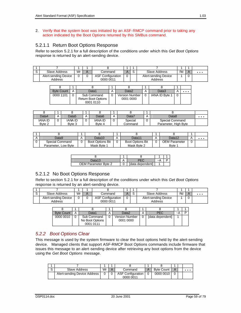
Alert Standard Format (ASF) Specification 1.03
DSP0114.doc 20 June 2001 Page 59 of 79
2. Verify that the system boot was initiated by an ASF-RMCP command prior to taking any action indicated by the Boot Options returned by this SMBus command.
5.2.1.1 Return Boot Options Response Refer to section 5.2.1 for a full description of the conditions under which this Get Boot Options response is returned by an alert-sending device.
1 7 1 1 8 1 1 7 1 1 S Slave Address Wr A Command A S Slave Address Rd A • • • Alert-sending Device
Address 0 0 ASF Configuration
0000 0011 0 Alert-sending Device
Address 1 0
8 1 8 1 8 1 8 1
Byte Count A Data1 A Data2 A Data3 A • • • 0000 1101 0 Sub Command
Return Boot Options 0001 0110
0 Version Number 0001 0000
0 IANA ID Byte 1 0
8 1 8 1 8 1 8 1 8 Data4 A Data5 A Data6 A Data7 A Data8 • • •
IANA ID Byte 2
0 IANA ID Byte 3
0 IANA ID Byte 4
0 Special Command
0 Special Command Parameter, High Byte
1 8 1 8 1 8 1 8 1 A Data9 A Data10 A Data11 A Data12 A • • • 0 Special Command
Parameter, Low Byte 0 Boot Options Bit
Mask Byte 1 0 Boot Options Bit
Mask Byte 2 0 OEM Parameter
Byte 1 0
8 1 8 1 1 Data13 A PEC ~A P
OEM Parameter Byte 2 0 [data dependent] 1
5.2.1.2 No Boot Options Response Refer to section 5.2.1 for a full description of the conditions under which this Get Boot Options response is returned by an alert-sending device. 1 7 1 1 8 1 1 7 1 1 S Slave Address Wr A Command A S Slave Address Rd A • • • Alert-sending Device
Address 0 0 ASF Configuration
0000 0011 0 Alert-sending Device
Address 1 0
8 1 8 1 8 1 8 1 1
Byte Count A Data1 A Data2 A PEC ~A P 0000 0010 0 Sub Command
No Boot Options 0001 0111
0 Version Number 0001 0000
0 [data dependent] 1
5.2.2 Boot Options Clear This message is used by the system firmware to clear the boot options held by the alert-sending device. Managed clients that support ASF-RMCP Boot Options commands include firmware that issues this message to an alert -sending device after retrieving any boot options from the device using the Get Boot Options message.
1 7 1 1 8 1 8 1 S Slave Address Wr A Command A Byte Count A • • • Alert-sending Device Address 0 0 ASF Configuration
0000 0011 0 0000 0010 0

Alert Standard Format (ASF) Specification 1.03
DSP0114.doc 20 June 2001 Page 60 of 79
8 1 8 1 8 1 1 Data1 A Data2 A PEC A P
Sub Command Clear Boot Options
0001 0101
0 Version Number 0001 0000
0 [data dependent] 0
5.3 Discovery and Status Messages
5.3.1 Device Type Poll Message The Device Type Poll message allows an SMBus master to further determine the characteristics of an SMBus 2.0 device that responds to an ARP cycle with the ASF bit of its Interface byte set to 1. The device, currently either an ASF-sensor or an alert-sending device, returns its ASF Function Bits: Bit(s) Meaning
7:4 Reserved for future assignment by this specification, set to 00b. 3 Set to 1b if the alert-sending device’s transport media is valid, or up. This bit is always 0b
for ASF-sensor devices.
2 Set to 1b if the alert-sending device has been configured with the information required to send PET frames. This bit is always 0b for ASF-sensor devices.
1:0 ASF Device Type, set to one of the following enumerated values:
11b Reserved for future definition by this specification. 10b The device is an ASF-sensor.
01b The device is an alert-sending device.
00h Reserved for future definition by this specification.
1 7 1 1 8 1 1 7 1 1 8 1 S Slave Address Wr A Command A S Slave Address Rd A Byte
Count A • • •
ASF Device Address
0 0 Sensor Device 0000 0001
0 ASF Device Address
1 0 0000 0011
0
8 1 8 1 8 1 8 1 1
Data1 A Data2 A Data3 A PEC ~A P Sub Command
Device Type Poll 0001 0011
0 Version Number 0001 0000
0 ASF Function Bits 0 [data dependent] 1
5.3.2 Set System State Message This message is used by the managed client’s firmware to record the client’s current System State into an alert-sending device. The alert-sending device reports the System State written by this message in subsequently issued ASF-RMCP System State Response (42h) messages; section 3.2.3.5 defines the format of the System State byte. Note: The alert-sending device is responsible for maintaining the System State information. After a reset, the alert-sending device reports the value as Unknown (1110b) until the device receives the first Set System State message. The Set System State message format is as follows:
1 7 1 1 8 1 8 1 8 1 S Slave Address Wr A Command A Byte Count A Data1 A • • • Alert-sending Device Address 0 0 System State
0000 0001 0 0000 0011 0 Sub Command
Set System State 0001 1000
0

Alert Standard Format (ASF) Specification 1.03
DSP0114.doc 20 June 2001 Page 61 of 79
8 1 8 1 8 1 1 Data 2 A Data3 A PEC A P
Version Number 0001 0000
0 System State
0 [data dependent] 0
5.4 Remote-Control Device Action Message An alert-sending device forces a remote control action to the managed client via a Remote-Control Device Action message. If the managed client supports ASF-RMCP remote-control actions, the client’s firmware publishes the remote-control device types and addresses via an ASF-defined ACPI data structure (see 4.1.2.4 ASF_RCTL ). That data structure contains the Control Device Address, Control Command, and Control Data Value fields that the alert-sending device uses in the SMBus message to force the device action. The data returned by that ACPI control method indicates whether or not a remote-control device’s command must include a PEC. An alert-sending device uses the SMBus Byte Write command to initiate the remote-control action, either … without a PEC:
1 7 1 1 8 1 8 1 1 S Slave Address Wr A Command A Write Data A P Control Device Address 0 0 Control Command 0 Control Data Value 0
… or with a PEC: 1 7 1 1 8 1 8 1 8 1 1 S Slave Address Wr A Command A Write Data A PEC A P Control Device Address 0 0 Control Command 0 Control Data Value 0 [data dependent] 0
5.5 Legacy Sensor Device Alert Poll Message An alert-sending device polls legacy sensors to determine if status bits are set, indicating that an alert should be sent. If the managed client supports ASF legacy-device alerts, the client’s firmware publishes the legacy-device configuration and access information via an ASF-defined ACPI data structure (see 4.1.2.2 ASF_ALRT). That structure contains the Alert Device Address and Alert Command fields that the alert-sending device uses in the SMBus message to read the legacy-device’s current status. The control method’s returned data also identifies compare conditions as well as PET field data that the alert-sending device uses to format a PET frame if the specified condition is active. See section 6.1.2 for additional information regarding the methods an alert-sending device uses in the polling of legacy-device sensors. The format of the message is an SMBus Byte Read transaction: Caution: This command is a Byte Read — an atomic write/read command. This is different than a combination of 2 separate commands: Send Byte and Receive Byte. To avoid multi-master problems, the atomic Byte Read must be used instead of the 2 individual commands. 1 7 1 1 8 1 1 7 1 1 8 1 1 S Slave Address Wr A Command A S Slave Address Rd A Read Result ~A P Legacy Sensor
Device Address 0 0 Alert
Command 0 Legacy Sensor
Device Address 1 0 1

Alert Standard Format (ASF) Specification 1.03
DSP0114.doc 20 June 2001 Page 62 of 79
6 SMBus Device Characteristics
This section describes the behavior and requirements for SMBus devices that are defined by this specification, ASF-sensor, legacy-sensor, and remote-control devices. The primary differences between these device types are summarized below. Legacy-sensor devices
• No well-defined or commonly accepted hardware interface for providing device information (e.g. manufacturer, class, etc.)
• Primitive mechanisms for generating and clearing alert events • No standard alert information associated with hardware events • Only supports fixed slave addresses ASF-sensor devices • Well-defined hardware interface for providing device information • A standard and consistent method for generating alert events regardless of sensor type • A standard SMBus packet format for processing alert events • Support for fixed address devices (i.e. system-resident) and dynamically addressed devices
(i.e. ARP-capable; PCI add-in card-resident) Remote Control devices • A defined SMBus transaction type (Byte Write). • System defined values for various remote control actions.
6.1 Legacy Sensor Devices If legacy sensor devices are included in an ASF managed client’s implementation, the client’s firmware identifies the characteristics and access methods for the devices via the ASF_ALRT ACPI data structure.
6.1.1 Sensor Requirements To limit the scope of sensors supported by an alert-sending device, the following behavior must be apply for a legacy-sensor device to be used in an ASF environment:
1. The alerts must be poll-able by doing an SMBus Byte Read message. 2. Individual status bits in the Byte Read’s Read Result value must identify the alerts. 3. The alert status bits must be either:
A. Level (always indicating the current status), or B. Automatically cleared after the Byte Read is done, but set again before the next Byte
Read if the event is still active. The legacy-sensor device must clear the status within the Minimum Legacy Sensor Poll Time specified by the managed client’s firmware, see 4.1.2.2 for more information.

Alert Standard Format (ASF) Specification 1.03
DSP0114.doc 20 June 2001 Page 63 of 79
4. All status bits returned by the device (in the Read Result data byte response to an SMBus Byte Read message) that are set to 1b within the device’s ASF_ALERTDATA Alert Data Mask must always be valid, regardless of the power state of the function monitored by that status bit. For example, if a bit indicates a CPU voltage low error, that bit must return 0b when the system is in a sleep state and the CPU is not powered or a false error will result. Alternatively, the implementation might cause the device to not respond to polling (by responding with a NACK to its SMBus address) during a low-power, sleep, or standby state. In this case, the alert -sending device will skip updating its event state information for this device until the device again responds to polling. It is the managed client’s responsibility to guarantee that the sensor reports valid data for each supported power state or that the sensor does not respond to polling cycles in the unsupported power states. This may be accomplished by hardware or software mechanisms. Note: If the implementation elects to have a device stop responding, it is the system’s responsibility to ensure that the alert-sending device does not get corrupted data if a power transition occurs during a legacy sensor polling cycle.
6.1.2 Usage of Firmware Legacy Sensor Device Alert Information An alert-sending device, acting as an SMBus master, periodically polls the legacy sensor device associated with each entry in the data structure described in section 4.1.2.3. Each entry contains the Alert Device Address and Alert Command values that an alert-sending device sets in an SMBus Legacy Sensor Device Alert Poll Message as defined in section5.5. These poll cycles are use to see whether the condition specified by the entry has been asserted. This process assumes two variables, current and past. The past variable must be set to 00h by the alert -sending device when the device is reset. The alert-sending device uses the procedure described below for each entry in the ASF_ALERTDATA structure:
1. Use the SMBus Read Byte protocol with the SMBus Slave Address field set to the entry’s Alert Device Address value and the SMBus Command Code field set to the entry’s Alert Command value.
2. Perform a bit-wise AND of the SMBus message’s Read Result with the entry’s Alert Data Mask value. The result of this operation is the current status.
3. Determine whether an assertion event has occurred or not. If so, the alert-sending device sends a PET frame that includes the Alert PET-related information in the entry. An assertion event has occurred if either of the following cases (A or B) are true: A. Bit Mask Assertion Event – true if all of the following are true:
i) Bit 0 of the entry’s Alert Device Address field is cleared (0b). ii) A bit in the current status is set and the entire past status is cleared.
B. Compare Byte Assertion Event – true if all of the following are true:
i) Bit 0 of the entry’s Alert Device Address field is set (1b). ii) A bit in the current status is different than the corresponding bit in the past status. iii) The current value matches the entry’s Alert Compare Value.
4. Determine whether a de-assertion event has occurred or not. If so, the alert-sending device sends a PET frame that includes the PET-related information in the entry and sets the de-assertion bit (bit 7) within the PET frame’s Event Offset field.. A de-assertion event has occurred if either of the following cases (A or B) are true: A. Bit Mask De-assertion Event – true if all of the following are true:
i) Bit 0 of the entry’s Alert Device Address field is cleared (0b).
ii) The entire current status is cleared and any bit in the past status is set. B. Compare Byte De-assertion Event – true if all of the following are true:

Alert Standard Format (ASF) Specification 1.03
DSP0114.doc 20 June 2001 Page 64 of 79
i) Bit 0 of the entry’s Alert Device Address field is set (1b). ii) A bit in the current status is different than the corresponding bit in the past status.
iii) The current value does not match the entry’s Alert Compare Value and the past value does match the entry’s Alert Compare Value.
5. The current status is copied into the past status.
6.2 ASF-Sensor Devices An ASF-Sensor device must meet the requirements detailed in this section and implement the following ASF SMBus commands:
• Get Event Data message for ASF Sensors (section 5.1.1.1)
• Get Event Status message for ASF Sensors (section 5.1.1.2)
• Device Type Poll message (section 5.3.1) This specification recommends that an ASF-sensor support all SMBus 2.0 protocols, including those required for discovery via ARP. Lower-cost, fixed-address ASF-sensor devices can be “discovered” by an alert-sending device via the managed client’s firmware methods, see section 4 for more information.
Note: Some SMBus 1.x and 2.0 host controllers do not support the SMBus 2.0 "Block Write-Block Read Process Call" transaction necessary to issue the Get Event Data and Get Event Status messages. An ASF-sensor designer might want to take this into consideration and design an alternate interface to enable the host controller to access the device’s event status and data.
6.2.1 Device Identification New sensor devices must implement the 128-bit Unique Device Identifier (UDID) as defined by [SMBUS_2.0]. New sensor devices that have fixed addresses are not required to support the full ARP command set; support for the directed Get UDID command is the only requirement. If a fixed-address device is not discoverable, the managed client’s firmware publishes the device’s fixed address in the ASF_ADDR information record. Recommended: New fixed-address ASF-sensor devices support the ARP commands necessary to support device discovery.
The UDID content is summarized below, but the format and content is controlled by [SMBUS_2.0].
8 bits
8 bits
16 bits
16 bits
16 bits
16 bits
16 bits
32 bits
Device Capabilities
Version / Revision
Vendor ID
Device ID
Interface Subsystem Vendor ID
Subsystem Device ID
Vendor Specific ID
MSB LSB
Device Capabilities
Describes the device’s capabilities, including the device’s address type and PEC support indications.
Version / Revision UDID version number, and silicon revision identification.
Vendor ID The device manufacturer’s ID as assigned by the SBS Implementers’ Forum or the PCI SIG.
Device ID The device ID as assigned by the device manufacturer (identified by the Vendor ID field).
Interface Identifies the protocol layer interfaces supported over the SMBus connection by the device. For example, ASF (bit 5) and IPMI.

Alert Standard Format (ASF) Specification 1.03
DSP0114.doc 20 June 2001 Page 65 of 79
Subsystem Vendor ID
This field may hold a value derived from any of several sources:
• The device manufacturer’s ID as assigned by the SBS Implementers’ Forum or the PCI SIG.
• The device OEM’s ID as assigned by the SBS Implementers’ Forum or the PCI SIG.
• A value that, in combination with the Subsystem Device ID, can be used to identify an organization or industry group that has defined a particular common device interface specification.
Subsystem Device ID
The subsystem ID identifies a specific interface, implementation, or device. The party identified by the Subsystem Vendor ID field defines the Subsystem ID.
Vendor-specific ID
A unique number per device.
6.2.2 Event Generation and Clearing Events reported by an ASF sensor must be level events from the alert-sending device perspective. This behavior allows the Alert Sending Device to detect the state transitions and send assertion and de-assertion alerts, and allows a managed client to include multiple alert-sending devices.
An implementer may choose to design a “sticky” event that requires a mechanism to be cleared. In these cases, the clear mechanism is outside the scope of the ASF specification. An example of a desired “sticky” event is a “chassis intrusion” detection circuit.
Note: Events monitored under the ASF context are intended to be low frequency and generally stable and monotonic. This is a general requirement due to the uncertain speed of the SMBus. This specification does not limit the event transition frequency of a sensor’s event. Instead, implementers are recommended to implement “sticky” events where critical events may have a transition frequency that may allow the event to go undetected.
6.2.3 Alert Status ASF-sensor devices will implement event generation and clearing with the following behavior:
• Sensor must contain an active-high, level-sensitive status register bit for each event; the sensor may also optionally implement an edge-triggered status bit for host system notification and event processing.
• The alert-sending device (e.g. NIC) is responsible for edge-detection of an event (i.e. the alert-sending device must recognize when the alert event is first generated).
• “Sticky” event status bits are cleared by the mechanisms unique to the managed client system (e.g. BIOS, DMI, CIM). The alert-sending device is not required to clear sticky event status.
Illustrated below is a conceptual example of an alert event logic structure with the optional edge-triggered bit for the host. For one event there are two register bits within the sensor device. The bit in the Poll Alert Register is simply the level-sensitive event. The bit in the Host Alert Register is implemented as a “sticky” bit; this bit is set when the event transitions from inactive to active and can only be cleared by some action taken by the host. This bit could also feed additional logic to generate a host system interrupt.

Alert Standard Format (ASF) Specification 1.03
DSP0114.doc 20 June 2001 Page 66 of 79
HostAlert
RegisterD
CQ
Poll AlertRegister
Host Clear
Event
6.2.4 Device Power On Reset Time ASF-sensor and remote-control devices are allowed up to 500ms to complete their Power On Reset once they have detected that their supply power is stable. These devices don’t appear on the SMBus (i.e. a NACK is generated for the associated slave address) before the device is prepared to communicate. Note: Alert-sending devices that begin communicating over the SMBus after auxiliary power has stabilized but before main power has stabilized must tolerate a change in available devices; there may be a mix of auxiliary powered and main powered types.
6.3 Remote Control Device If remote-control devices are included in an ASF managed client’s implementation, the client’s firmware identifies the characteristics and access methods for the devices via the ASF_RCTL ACPI data structure.
6.3.1 Device Requirements Beyond the SMBus transaction requirements in section 5.4, remote-control devices must meet the following requirements: 1. The remote control actions must be write-able by doing an SMBus Byte Write transaction.
2. The remote control action must be initiated immediately by the managed client system’s hardware after the Remote-Control Device Action Message is issued by the alert-sending device.
3. The remote control actions must work independent of local client software support.
6.3.2 Usage of Firmware Remote Control Device Information An alert-sending device, acting as an SMBus master, will issue SMBus Remote Control actions when the appropriate RMCP remote control packet is received (see 3.2.3.1 and 3.2.3.2 for more information). For the appropriate remote control action, the ASF_RCTL fields Control Device Address, Control Command, and Control Data Value are used for the SMBus Device Address, Command, and Data Write, respectively. Additionally, bit 0 of the ASF_RCTL Control Device Address field determines whether (1) or not (0) a PEC is appended to the Byte Write command by the alert-sending device.
6.3.3 Remote Control Functions The remote control functions supported by this specification are defined here; the duration of each of these operations is managed client system-specific.
Reset

Alert Standard Format (ASF) Specification 1.03
DSP0114.doc 20 June 2001 Page 67 of 79
The reset function causes a low latency reset of the system. This reset must, at a minimum, reset the host processor(s) and cause PCI Reset# to be asserted so that all devices on the PCI bus are initialized. If supported, the reset function is required to produce the reset in these system states:
• S0/G0 “working”
• S1
• S2
• S3
• Legacy ON state.
• Sleeping in an S1, S2, or S3 state, or Legacy SLEEP
• G1 sleeping Operation in all other system states is undefined by this specification.
Power-Up
The power-up function brings a sleeping system into the S0/G0 “working” state or into the Legacy ON state. If supported, the power-up function is required to produce the power-up in any of these sleeping states:
• S4
• S5/G2
• S4/S5 soft-off
• S5 entered by override
• Legacy OFF Operation in all other system states is undefined by this specification.
Unconditional Power-Down
The unconditional power-down function forces the system into an S5 entered by override or a Legacy OFF powered off state. This power-down occurs without any blocking from software or the system. Because of this, ACPI and system state context is not guaranteed to be preserved.
The unconditional power-down function is required to produce the power-down in these system states:
• S0/G0 “working”
• S1
• S2
• S3
• Legacy ON state
• Sleeping in an S1, S2, or S3 state, or Legacy SLEEP
• G1 sleeping Operation in all other system states is undefined by this specification.
Power Cycle Reset
The power cycle reset function causes a hard reset of the system. This reset must be functionally equivalent to an Unconditional Power-Down operation, followed by a Power Up operation. If supported, the power cycle reset function is required to produce the reset in these system states:
• S0/G0 “working”
• S1
• S2

Alert Standard Format (ASF) Specification 1.03
DSP0114.doc 20 June 2001 Page 68 of 79
• S3
• Legacy ON state
• Sleeping in an S1, S2, or S3 state, or Legacy SLEEP
• G1 sleeping. Operation in all other system states is undefined by this specification.

Alert Standard Format (ASF) Specification 1.03
DSP0114.doc 20 June 2001 Page 69 of 79
Appendix A Additions to PET Specification 1.0
A.1 Modem Support There needs to be a new entry for the Trap Source Type and Event Source type for Modems. 60h – 67h
A.2 Battery Sensor To support system battery-related events a new Event Sensor Type along with a set of Sensor-specific Offsets should be added as follows:
Battery 29h 00h Battery low 01h Battery failure 02h Battery removed
A.3 System Firmware Error/Progress Descriptor To support industry-standard system progress and error handling, the “POST Error” Sensor Type defined by [PET_1.0] is renamed and extended as described below.
Sensor Type Sensor Type Code
Sensor-specific Offset
Event
00h Standard System Firmware Error. The Event Data 2 field contains a further error descriptor, as described in 3.1.5.2 System Firmware Error Events
01h Standard System Firmware Hang. The Event Data 2 field contains a further error descriptor, as described in 3.1.5.3 System Firmware Progress Events.
02h Standard System Firmware Progress. The Event Data 2 field contains a further progress descriptor, as described in 3.1.5.3 System Firmware Progress Events.
03h OEM-specific System Firmware Error.
04h OEM-specific System Firmware Hang Error
System Firmware Error/Progress Descriptor
0Fh
05h OEM-specific System Firmware Progress
A.4 Device Relative Entity Instances The present PET specification defines an Entity Instance number that identifies different instances of the same entity type in the system. For example, if you have three fans, the entity instance value allows you to tell one fan from another by allowing an Entity Instance number to be assigned. Typically, a system with three fans would assign instance numbers 1, 2, and 3 to the fans - though there is no requirement that instance numbers be consecutive or sequential starting from 1. The Entity Instance numbers are presently assigned relative to the entire system. Which means that a given number can only be used once in the entire system. This leads to a problem for add-in devices, or pre-configured sub-systems. For example, you could not pre-assign entity instance numbers to entities on an add-in card, because if you put two identical cards in the system, their instance numbers would conflict.
Thus, the definition of Entity Instance number needs to be changed to allow sensor device relative instance numbers. The following table shows the proposed change to accomplish this by splitting the entity instance number into two ranges: one for system relative and another for sensor device relative.
Table , Entity Instance Number

Alert Standard Format (ASF) Specification 1.03
DSP0114.doc 20 June 2001 Page 70 of 79
Bit Description
7 0 = physical entity, 1 = logical entity
6:0 Entity Instance number 00h-5Fh = system relative 60h-7Fh = sensor device relative
00h-5Fh = System Relative. Instance number must be unique for each different entity of type Entity ID in the system. This range is used for devices that have a fixed enumeration (i.e. Not add in cards) 60h-7Fh = Sensor Device Relative. Instance number is unique for each different entity of type Entity ID for the sensor device that provides access to the sensors for the entity. The entity is uniquely identified by the combination of the Sensor Device number and the Entity Instance number. Note that when using a Sensor Device Relative instance number, all sensors for the entity must be provided by one sensor device. Otherwise, it may appear that there are more instances of the entity than are actually present. For example, suppose an add-in card has monitoring for both fan current and fan speed for a single fan. If the fan current was monitored via sensor device 2 and the fan speed monitored via sensor device 1, then the trap for fan current would return sensor device number 1 and a trap for fan speed would return sensor device number 2. Because the sensor device number is now part of what identifies a unique entity, software would view these traps as being from different fans, even if the Sensor Device Relative instance number were the same.
A.5 Event Source Type A range for an ASF Event Source Type must be added to the PET specification to support the proper PET frame from an ASF entity. This text below is the proposed addition to the Event Source Type definition of the PET specification:
ASF 68h – 6Fh
A.6 Sensor Type = 23h (Watchdog 2) Updates This sensor type defines Event Data 2 values that further describe the system state at the time of the watchdog event. The possible values for the “timer use at expiration”, present in bits 3:0 of this field must be extended to provide a discrete code to describe a system boot failure:
6h = System boot failure.
A.7 IPMI 1.0 Entity IDs A mismatch between [PET_1.0] and [IPMI_1.0] was found in the Entity IDs table. The following changes are required to make [PET] match [IPMI_1.0]:
Code Entity
19d power unit / power domain (typically used as a pre-defined logical entity for grouping power
20d power module / converter
21d power management / power distribution board
22d chassis back panel board
23d system chassis
24d sub-chassis
25d Other chassis board
26d Disk Drive Bay
27d Peripheral Bay

Alert Standard Format (ASF) Specification 1.03
DSP0114.doc 20 June 2001 Page 71 of 79
28d Device Bay
29d fan / cooling device
30d cooling unit (can be used as a pre-defined logical entity for grouping fans or other cooling devices)
31d cable / interconnect
32d memory device (This Entity ID should be used for replaceable memory devices, e.g. DIMM/SIMM. It is recommended that Entity IDs not be used for individual non-replaceable memory devices. Rather, monitoring and error reporting should be associated with the FRU [e.g. memory card] holding the memory.)
33d System Management Software
34d BIOS
35d Operating System
36d system bus
37d Group - this is a logical entity for use with Entity Association records. It is provided to allow a sensor data record to point to an Entity-association record when there is no appropriate pre-defined logical entity for the entity grouping. This Entity should not be used as a physical entity.
A.8 Entity and Sensor support for Alert Sending Devices This value is added to the Entity ID table to allow for better reporting from an ASF Sending Device:
Code Entity
38d Out of Band (OOB) Management Communication Device
This value is added to the Sensor Types table to allow for better reporting from an ASF Sending Device:
Sensor Type Sensor Type Code
Sensor-Specific Offset
Event
Management Subsystem Health 28h - -

Alert Standard Format (ASF) Specification 1.03
DSP0114.doc 20 June 2001 Page 72 of 79
Appendix B ASF Entity Section Map
This section identifies the relevant ASF specification sections for each type of ASF entity:
B.1 Alert Sending Device 3.1.1 PET Frame Behavior 3.1.2 Agent Address Field 3.1.3 Specific Trap Field 3.1.4 Variable Bindings Fields 3.1.5.5 System Heartbeat 3.1.5.6 System Boot Failure
RMCP Packet Format 3.2.3 ASF RMCP Message Types 3.2.4 RMCP Usage Scenarios 4.1.2.1 ASF_INFO 4.1.2.2 ASF_ALRT 4.1.2.3 ASF_ALERTDATA 4.1.2.5 ASF_CONTROLDATA 5 ASF SMBus Messages 5.1.1.1 Get Event Data 5.1.1.2 Get Event Status 5.1.4.1 Start Watchdog Timer 5.1.4.2 Stop Watchdog Timer 5.1.5.1 Message with Retransmission 5.1.5.2 Message without Retransmission 5.2.1 Get Boot Options 5.2.1.1 Return Boot Options 5.2.1.2 No Boot Options 5.2.2 Boot Options Clear 5.3.1 Device Type Poll Message 6 SMBus Device Characteristics 6.1.1 Sensor Requirements 6.1.2 Usage of Firmware Legacy Sensor Device Alert Information 6.2 ASF-Sensor Devices 6.2.1 Device Identification 6.2.2 Event Generation and Clearing 6.2.3 Alert Status 6.2.4 Device Power On Reset Time 6.3.1 Device Requirements 6.3.2 Usage of Firmware Remote Control Device Information 6.3.3 Remote Control Functions
B.2 Legacy Sensor 4.1.2.2 ASF_ALRT 4.1.2.3 ASF_ALERTDATA 6 SMBus Device Characteristics 6.1.1 Sensor Requirements
B.3 ASF Sensor 3.1.3 Specific Trap Field
Alert Standard Format (ASF) Specification 1.03
DSP0114.doc 20 June 2001 Page 73 of 79
3.1.4 Variable Bindings Fields 3.1.5.1 Environmental Events 4.1.2.1 ASF_INFO 5.1.1.1 Get Event Data 5.1.1.2 Get Event Status 6 SMBus Device Characteristics 6.2 ASF-Sensor Devices 6.2.1 Device Identification 6.2.2 Event Generation and Clearing 6.2.3 Alert Status 6.2.4 Device Power On Reset Time
B.4 Remote Control Device 4.1.2.5 ASF_CONTROLDATA 6 SMBus Device Characteristics 6.3.1 Device Requirements 6.3.2 Usage of Firmware Remote Control Device Information 6.3.3 Remote Control Functions
B.5 Firmware 3.1.5.2 System Firmware Error Events 3.1.5.3 System Firmware Progress Events 4 Firmware Interfaces 4.1 ACPI Definitions 4.1.1 Control Methods 4.1.2.1 ASF_INFO 4.1.2.2 ASF_ALRT 4.1.2.3 ASF_ALERTDATA 4.1.2.4 ASF_RCTL 4.1.2.5 ASF_CONTROLDATA 4.1.2.7 5.1.4.1 Start Watchdog Timer 5.1.4.2 Stop Watchdog Timer 5.1.5.1 Message with Retransmission 5.1.5.2 Message without Retransmission 5.2.1 Get Boot Options 5.2.1.1 Return Boot Options 5.2.1.2 No Boot Options 5.2.2 Boot Options Clear 5.3.1 Device Type Poll Message
B.6 Operating System 3.1.5.4 OS Events 5.1.4.1 Start Watchdog Timer 5.1.4.2 Stop Watchdog Timer 3.2.4 RMCP Usage Scenarios
B.7 Local Alert Configuration Software 3.1.1 PET Frame Behavior 3.1.2 Agent Address Field 3.1.3 Specific Trap Field 3.1.4 Variable Bindings Fields 3.1.5.5 System Heartbeat 3.1.5.6 System Boot Failure

Alert Standard Format (ASF) Specification 1.03
DSP0114.doc 20 June 2001 Page 74 of 79
3.2.4 RMCP Usage Scenarios 4.1.2.1 ASF_INFO 4.1.2.2 ASF_ALRT 4.1.2.3 ASF_ALERTDATA 4.1.2.4 ASF_RCTL 4.1.2.5 ASF_CONTROLDATA 4.1.2.7 5.1.4.1 Start Watchdog Timer 5.1.4.2 Stop Watchdog Timer 5.3.1 Device Type Poll Message
B.8 Remote Console Software 3.1.1 PET Frame Behavior 3.1.2 Agent Address Field 3.1.3 Specific Trap Field 3.1.4 Variable Bindings Fields RMCP Packet Format 3.2.3 ASF RMCP Message Types 3.2.4 RMCP Usage Scenarios

Alert Standard Format (ASF) Specification 1.03
DSP0114.doc 20 June 2001 Page 75 of 79
Appendix C ASF Entity Function Checklists
This section contains the entity-specific checklists that define requirements and recommendations for an ASF implementation.
C.1 Alert Sending Device The following table identifies the required and optional features for an ASF alert-sending device. See also C.2 Local Alert -Sending Device Configuration Software. Table D-1 Alert-Sending Device Checklist for ASF Implementations
#### Description
AS1 The device includes an SMBus 2.0-compliant master/slave controller, and external connection to a system’s SMBus.
Required
AS2 The device re-transmits PET frames, and meets the functionality described in section 3.1.1.
Required
AS3 The device sets the Agent Address field of any transmitted PET’s Protocol Data Unit per the RFC associated with the transport method, see section 3.1.2.
Required
AS4 The device supports the IPv4 (IP version 4) protocol. Required
AS5 The device statically assigns the Trap Source Type field of issued PETs to identify the type of the source device, see section 3.1.4.
Required
AS6 The device supports transmission of a system heartbeat message, see 3.1.5.5. Optional
AS7 The device includes a watchdog timer. Required
AS8 The device implements the functionality required to support a system boot-failure alert; see 3.1.5.6.
Required
AS9 The device provides support for all ASF-RMCP message types and formats described in section 3.2 that have an IANA Enterprise Number value of 4542 (ASF).
Required
AS10 The device provides support for RMCP Message Class values other than 6 (ASF). Optional
AS11 The device provides support for ASF-RMCP messages that have an IANA Enterprise Number value other than 4542 (ASF).
Optional
AS12 The device responds to RMCP control messages (see 3.2.3.1 and 3.2.3.2) as configured by its OS-present configuration software.
Required
AS13 If the device has not been configured, it does not respond to RMCP control messages (see 3.2.3.1 and 3.2.3.2).
Required
AS14 If there are legacy sensors in the system (as described in the system’s ACPI implementation, see 4.1.2.2 ASF_ALRT), the alert-sending device periodically polls the devices to determine the devices’ current status and sends any associated ASF alerts. Refer to 6.1.2 for additional information.
Required
AS15 If there are legacy sensors in the system, the alert-sending device uses a 4-second Minimum Legacy Device Poll Time.
Required
AS16 The device polls ASF sensors using the system -specified Inter-poll Wait Time (see 4.1.2.1), as stored by the device’s configuration software in device-specific non-volatile memory.
Required
AS17 If there are ASF sensors in the system, the alert-sending device issues periodic SMBus Get Event Data and/or Get Event Status messages to determine the devices’ current status and sends any associated ASF alerts.
Required
AS18 The device responds to the SMBus Device Type Poll message, see 5.3.1. Required
AS19 The device maintains its current link status, and reports this status in the Device Type Poll response.
Required

Alert Standard Format (ASF) Specification 1.03
DSP0114.doc 20 June 2001 Page 76 of 79
#### Description
AS20 The device responds to the SMBus Set System State message (see 5.3.2) and returns the last value written in response to an RMCP System State Request (see 3.2.3.8). If no value is written by the system firmware, the device responds with an System State value of “Unknown”.
Required
AS21 The device responds to the SMBus Start Watchdog Timer and Stop Watchdog Timer messages, issuing the associated ASF alert if the timer is not reset within the required amount of time.
Required
AS22 The device responds to the SMBus Boot Options messages (see 5.2). Required
AS23 The device responds to the SMBus Push messages (with and without retransmission) and transmits the requested ASF alerts.
Required
AS24 A system board-set device (e.g. soldered onto the motherboard) has an assignable SMBus device address.
Optional
AS25 A device on a card that plugs into an expansion bus has an assignable SMBus device address.
Required
AS26 The device supports AS12, AS15, and AS18 features for all system states from which the device is configurable to accept packets to wake the system.
Required
C.2 Local Alert-Sending Device Configuration Software The following table identifies the required and optional features for the OS-present configuration software provided with an alert-sending device: Table D-2 Local Alert Configuration Software Checklist for ASF Implementations
#### Description
CS1 The configuration software programs non-volatile memory for the alert-sending device with the Minimum Watchdog Reset Value, Minimum ASF Sensor Inter-poll Wait Time, Manufacturer ID, and System ID values present in the system firmware’s ACPI implementation (see 4.1.2.1 ASF_INFO).
Required
CS2 The configuration software programs non-volatile memory for the alert-sending device with the managed client’s UUID, as found in the system firmware’s SMBIOS System Information structure.
Required
CS3 If the alert-sending device supports system heartbeat messages, the device’s configuration software provides a user-settable rate at which the messages are transmitted and a method through which to disable the messages entirely.
Required
CS4 If the managed client supports legacy-device alerts (as described in the system’s ACPI implementation, see 4.1.2.2 ASF_ALRT) the alert-sending device’s configuration software enables the device to send PET alerts based on the legacy-device status. Refer to 4.1.2.2 and 6.1.2 for additional information.
Required
CS5 The configuration software, when running on an ACPI-aware operating system, sets its alert-sending device’s power-on wait time (via the ACPI SPWT control method) to the maximum of the device’s fixed time and the value returned by the GPWT ACPI control method.
Required
CS6 If the managed client supports RMCP control messages (as described in the system’s ACPI implementation, see 4.1.2.4 ASF_RCTL and 4.1.2.6 ASF_RMCP) the alert-sending device’s configuration software records the system -specific information into the device’s non-volatile memory to enable the device to respond to the messages. Refer to 3.2.3.1 and 3.2.3.2 for additional information.
Required
CS7 The configuration software records the device’s TCP/IP address into its non-volatile memory.
Required
CS8 The configuration software gathers the TCP/IP address of the management console to which alerts are sent, and records this address into the device’s non-volatile memory.
Required

Alert Standard Format (ASF) Specification 1.03
DSP0114.doc 20 June 2001 Page 77 of 79
C.3 Legacy Sensor The following table identifies the required and optional features for an ASF legacy sensor. Table D-3 Legacy Sensor Checklist for ASF Implementations
#### Description
LS1 The device’s alerts are pollable via an SMBus Byte Read command. Required
LS2 Individual status bits in the Read Result value returned by an SMBus Byte Read identify the device’s alerts.
Required
LS3 All status bits returned by the device that are set to 1b within the Alert Data Mask published by the system firmware must always be valid. See 6.1.1 for more information.
Required
LS4 The alert status bits must be either level or automatically cleared after an SMBus Byte Read, but set again before the next Byte Read if the event is still active. See 6.1.1 for more information.
Required
LS5 The device responds to its address within 4 seconds (the Minimum Legacy Sensor Poll Time).
Required
C.4 ASF Sensor The following table identifies the required and optional features for an ASF sensor. Table D-4 ASF Sensor Checklist for ASF Implementations
#### Description
SD1 The device is compliant with [SMBUS_2.0]. Required
SD2 The device, present on an expansion-bus card, supports an assignable SMBus address.
Required
SD2 The device, present on the system board-set (e.g. soldered onto the motherboard), supports an assignable SMBus address.
Optional
SD3 The device supports the SMBus Device Type Poll message (see 5.3.1), responding with ASF Function Bits set to 02h to indicate that it is an ASF sensor device.
Required
SD4 The device supports the SMBus Get Event Data and Get Event Status messages (see 5.1.1).
Required
SD5 The device’s SMBus 2.0 UDID identifies the device as supporting ASF methods by setting bit 5 of the UDID Interface field to a 1.
Required
SD6 The sensor contains an active-high (logic level 1), level-sensitive status register for each event reported by the sensor.
Required
SD7 The sensor completes its power-on reset (POR) in 500 milliseconds from detection of stable supply power.
Required
SD8 The device supports SMBus PEC protocols for ASF-defined messages. Required
C.5 Remote Control Device The following table identifies the required and optional features for a system’s remote-control devices, i.e. the SMBus devices accessed by the alert -sending device to cause the system to power cycle, reboot, power on, or power off. Table D-5 Remote Control Device Checklist for ASF Implementations
#### Description
RD1 The device supports the SMBus Byte Write transaction to set the remote-control action.
Required
RD2 The remote-control action is initiated immediately after the alert-sending device sends the associated Byte Write SMBus message.
Required
RD3 The device supports its associated remote-control action as described in section 6.3.3.
Required

Alert Standard Format (ASF) Specification 1.03
DSP0114.doc 20 June 2001 Page 78 of 79
#### Description
RD4 The device supports SMBus PEC protocols. Optional
C.6 System Firmware The following table identifies the required and optional features for a managed client’s firmware ASF implementation. Table D-6 System Firmware Checklist for ASF Implementations
#### Description
SF1 System includes an SMBIOS implementation, compliant with v2.3 or later of [SMBIOS].
Required
SF2 System includes an ACPI implementation, compliant with v1.0b or later of [ACPI] Required
SF3 The system’s ACPI implementation contains a single ASF device with PnP ID of “ASF0001” and provides support for the GPWT and SPWT control methods.
Required
SF4 The system’s ACPI implementation includes the ASF_INFO information record in its ASF! ACPI description table.
Required
SF5 If the system includes legacy alert-source devices, and those devices’ alerts are to be handled by an ASF-aware alerting device, the ACPI ASF! description table includes an ASF_ALRT information record.
Required
SF6 If the system includes devices that provide ASF RMCP system actions to an ASF-aware alerting device, the system’s ACPI ASF! description table includes an ASF_RCTL information record.
Required
SF7 If the system includes SMBus devices that are not discoverable, the system’s ACPI ASF! description table includes an ASF_ADDR information record.
Required
SF8 If feature SF6 is implemented, at most one (1) of these information records is present, and that structure can specify at most eight (8) device alerts.
Required
SF9 The system’s SMBIOS implementation contains a System Information structure that provides the system’s UUID/GUID.
Required
SF10 If the system supports an OS boot failure alert, the system’s ACPI implementation includes a Metolious [MTLS] “OS Boot Failure” System Hang Watchdog device and its associated control methods.
Required
SF11 If the system supports ASF RMCP capabilities, the system’s ACPI ASF! description table contains an ASF_RMCP information record.
Required
SF20 The system firmware implements one or more System Firmware Error Events. Optional
SF21 The system firmware implements one or more System Firmware Progress Events. Optional
SF22 The system firmware issues the SMBus Stop Watchdog Timer message within Minimum Watchdog Timer Reset Value seconds to disable the initial boot-failure watchdog timer in the alert-sending device.
Required
SF23 If the system supports ASF RMCP capabilities, the system firmware issues the SMBus Get Boot Options message as early as possible in its boot process to retrieve the boot options sent with the last received RMCP command, and subsequently issues the SMBus Clear Boot Options message to signify that the firmware has retrieved the options for the current boot. Boot Options information retrieved from the Get Boot Options message is reported by the firmware in the system’s ACPI ASF_RMCP structure.
Required
SF24 The system firmware locates the alert-sending devices in the system by issuing the SMBus Device Type Poll Message and examining the results of that message.
Required
SF25 The system firmware issues the SMBus Set System State Message on system sleeping-state transitions.
Optional

Alert Standard Format (ASF) Specification 1.03
DSP0114.doc 20 June 2001 Page 79 of 79
#### Description
SF51 The system identifies all fixed-address SMBus devices that are undiscoverable, including legacy devices, using a Fixed SMBus Addresses (SEEPROM Record Type 06h) record in an SMBus SEEPROM.
Optional
SF52 The system identifies all fixed-address SMBus devices, even those that are discoverable.
Optional
SF53 If the system includes legacy alert-source devices, and those devices’ alerts are to be handled by an ASF-aware alerting device, the system identifies the legacy-device alert capabilities using an ASF Legacy-Device Alerts (SEEPROM Record Type 07h) record in an SMBus SEEPROM.
Optional
SF55 If the system includes devices that provide ASF RMCP system actions to an ASF-aware alerting device, the system identifies the access methods using an ASF Remote Control (SEEPROM Record Type 08h) record in an SMBus SEEPROM.
Optional
C.7 Management Console Software