specification for magnetic card reader … sheets/panasonic semiconductors... · specification for...
TRANSCRIPT

Specification No.:MIS-DG60B123
SPECIFICATION for MAGNETIC CARD READER
BUILT IN RS232
Model #
ZU-1870MA8R2
Revision 1.00
JUL 2004
Matsushita Electrical Industrial Co., Ltd. Matsushita Industrial Information Equipment Co., Ltd.

MAGNETIC CARD READER SPECIFICATION
© 2004 Matsushita Industrial Information Equipment Co., Ltd. MIS-DG60B123i
Copyright © 2004 Panasonic / Matsushita Industrial Information Equipment Co., Ltd. All rights reserved. Panasonic is a registered trademark of Matsushita Electric Industrial Co., Ltd. Other company, product, and service names may be trademarks or service marks of others.
REVISIONS Revision No. Date Description Page
1.00 1 JUL 2004 Initial Release All
Information in this document is subject to change without notice. No part of this document may be reproduced or transmitted in any form or by any means, electronic or mechanical, for any purpose, without the express written permission of Panasonic / Matsushita Industrial Information Equipment Co., Ltd. In case there is any contradiction appeared based on technical standard change/update etc., our specifications shall take precedence over such change/update.

MAGNETIC CARD READER SPECIFICATION
© 2004 Matsushita Industrial Information Equipment Co., Ltd. MIS-DG60B123ii
PRECAUTIONS READ THIS SECTION CAREFULLY BEFORE INSTALLING OR USEING THIS READER MODULE.
• Usage
Avoid Extreme Heat and Cold Do not store or use the reader module in locations exposed to heat, direct sunlight, or extreme cold. Avoid moving the device with which it was incorporated between locations with large temperature differences. If the moisture condensation should occur, do not use the device. Operation: -10 °C to +50 °C Storage: -20 °C to +60 °C Avoid Humidity, Liquids and Dust Do not store or use the reader module in locations exposed to high humidity, liquids (include rain) or dust. If used in dusty conditions, the magnetic head life will be shortened. Avoid Corrosive Gases Keep the reader module away from oil or corrosive gases (salt, brimstone, chlorine, acid, alkali, etc.). Avoid Radio Frequency Interference Do not use the reader module near a television or radio receiver. Avoid Magnetic Fields Keep the reader module away from magnets and magnetic field sources, such as high voltage, strong electrical current, magnetic security devices or industrial equipment (speakers, microwave ovens and CRT display, etc.). Avoid Locations Near Electrical Appliances or Other Devices that Emit Electrical Noise Keep the reader module away from electrical noise sources, such as electric motors, printer, or computer equipment. Keep Clean the Magnetic Head Dirt, metal dust and magnetic particles etc. may cause read error. You need to clean the magnetic head using the cleaning cards. Cleaning is recommended every week or when read problems occur. Do Not Apply More than the Specified Voltages Do not apply any reverse voltage. Voltage: DC +4.75 V to +12 V Do Not Use a Cracked or Deformed Card Store the card with caution to prevent dirt, scratch and distortion. No foreign matter should be stuck on the magnetic stripe surface. Use of such card may result in a read error.
MAGNETIC CARD READER SPECIFICATION
© 2004 Matsushita Industrial Information Equipment Co., Ltd. MIS-DG60B123iii
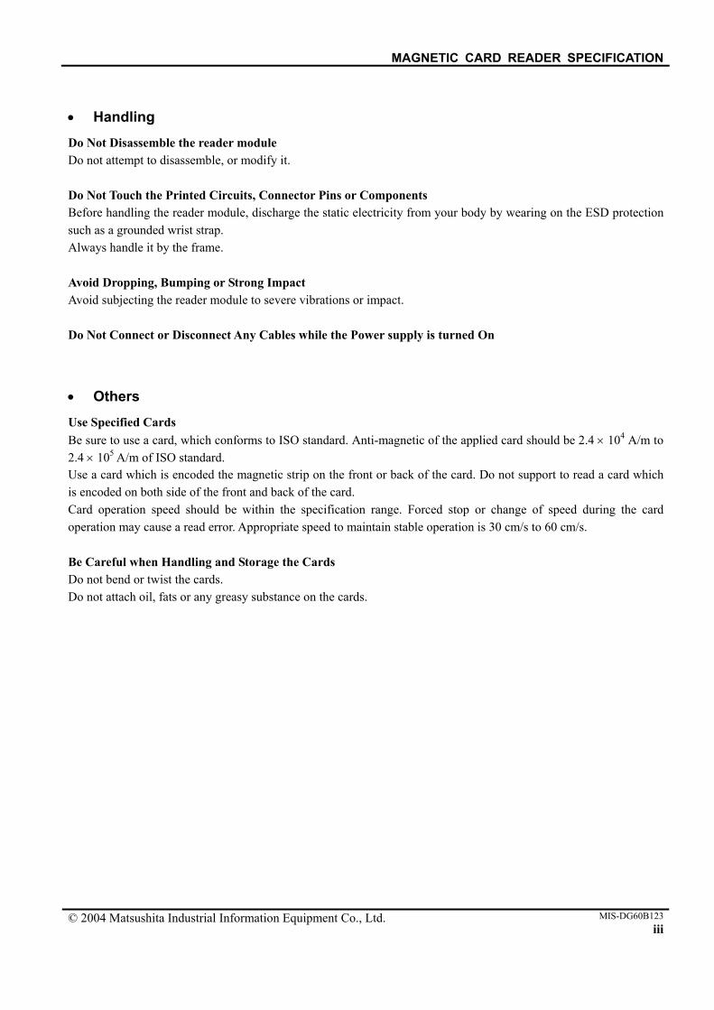
• Handling
Do Not Disassemble the reader module Do not attempt to disassemble, or modify it. Do Not Touch the Printed Circuits, Connector Pins or Components Before handling the reader module, discharge the static electricity from your body by wearing on the ESD protection such as a grounded wrist strap. Always handle it by the frame. Avoid Dropping, Bumping or Strong Impact Avoid subjecting the reader module to severe vibrations or impact. Do Not Connect or Disconnect Any Cables while the Power supply is turned On
• Others
Use Specified Cards Be sure to use a card, which conforms to ISO standard. Anti-magnetic of the applied card should be 2.4 × 10⁴ A/m to 2.4 × 10⁵ A/m of ISO standard. Use a card which is encoded the magnetic strip on the front or back of the card. Do not support to read a card which is encoded on both side of the front and back of the card. Card operation speed should be within the specification range. Forced stop or change of speed during the card operation may cause a read error. Appropriate speed to maintain stable operation is 30 cm/s to 60 cm/s. Be Careful when Handling and Storage the Cards Do not bend or twist the cards. Do not attach oil, fats or any greasy substance on the cards.
MAGNETIC CARD READER SPECIFICATION
© 2004 Matsushita Industrial Information Equipment Co., Ltd. MIS-DG60B123iv
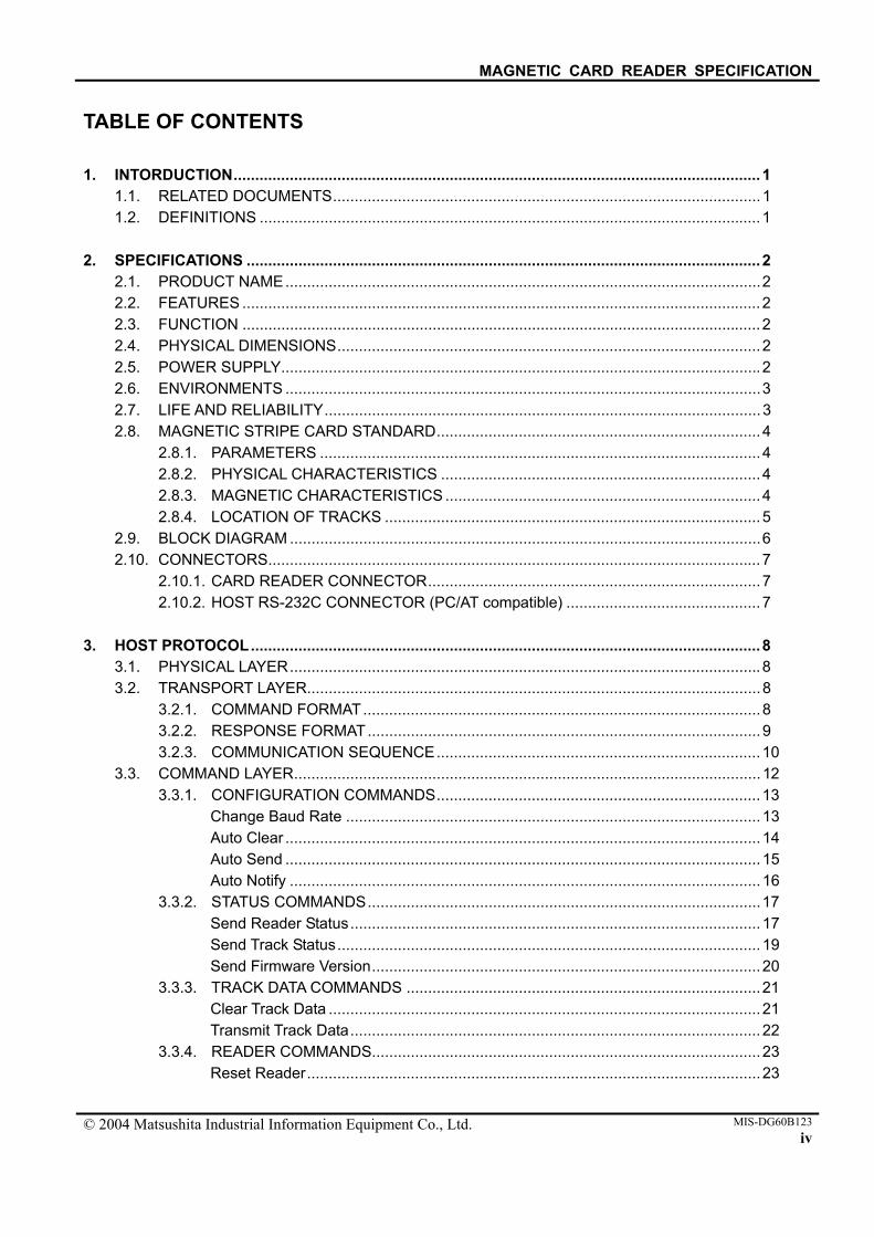
TABLE OF CONTENTS 1. INTORDUCTION..........................................................................................................................1
1.1. RELATED DOCUMENTS...................................................................................................1 1.2. DEFINITIONS ....................................................................................................................1
2. SPECIFICATIONS .......................................................................................................................2
2.1. PRODUCT NAME..............................................................................................................2 2.2. FEATURES ........................................................................................................................2 2.3. FUNCTION ........................................................................................................................2 2.4. PHYSICAL DIMENSIONS..................................................................................................2 2.5. POWER SUPPLY...............................................................................................................2 2.6. ENVIRONMENTS ..............................................................................................................3 2.7. LIFE AND RELIABILITY.....................................................................................................3 2.8. MAGNETIC STRIPE CARD STANDARD...........................................................................4
2.8.1. PARAMETERS ......................................................................................................4 2.8.2. PHYSICAL CHARACTERISTICS ..........................................................................4 2.8.3. MAGNETIC CHARACTERISTICS .........................................................................4 2.8.4. LOCATION OF TRACKS .......................................................................................5
2.9. BLOCK DIAGRAM .............................................................................................................6 2.10. CONNECTORS..................................................................................................................7
2.10.1. CARD READER CONNECTOR.............................................................................7 2.10.2. HOST RS-232C CONNECTOR (PC/AT compatible) .............................................7
3. HOST PROTOCOL......................................................................................................................8
3.1. PHYSICAL LAYER.............................................................................................................8 3.2. TRANSPORT LAYER.........................................................................................................8
3.2.1. COMMAND FORMAT............................................................................................8 3.2.2. RESPONSE FORMAT...........................................................................................9 3.2.3. COMMUNICATION SEQUENCE...........................................................................10
3.3. COMMAND LAYER............................................................................................................12 3.3.1. CONFIGURATION COMMANDS...........................................................................13
Change Baud Rate ................................................................................................13 Auto Clear ..............................................................................................................14 Auto Send ..............................................................................................................15 Auto Notify .............................................................................................................16
3.3.2. STATUS COMMANDS...........................................................................................17 Send Reader Status...............................................................................................17 Send Track Status..................................................................................................19 Send Firmware Version..........................................................................................20
3.3.3. TRACK DATA COMMANDS ..................................................................................21 Clear Track Data ....................................................................................................21 Transmit Track Data...............................................................................................22
3.3.4. READER COMMANDS..........................................................................................23 Reset Reader.........................................................................................................23
MAGNETIC CARD READER SPECIFICATION
© 2004 Matsushita Industrial Information Equipment Co., Ltd. MIS-DG60B123v
4. MAINTENANCE...........................................................................................................................24 5. APPEARANCE ............................................................................................................................25

MAGNETIC CARD READER SPECIFICATION
© 2004 Matsushita Industrial Information Equipment Co., Ltd. MIS-DG60B1231
1. INTRODUCTION This specification describes Panasonic’s manual insertion type Magnetic Card Reader (UCI-MAG) with built in RS232 interface and decoder.
1.1. RELATED DOCUMENTS ISO/IEC 7810:2003 Identification cards – Physical characteristics ISO/IEC 7811-1:2002 Identification cards – Recording technique – Part 1: Embossing ISO/IEC 7811-2:2001 Identification cards – Recording technique – Part 2: Magnetic stripe – Low coercively ISO/IEC 7811-3:1995 Identification cards – Recording technique – Part 3: Location of embossed characters on
ID-1 ISO/IEC 7811-4:1985 Identification cards – Recording technique – Part 4: Location of read-only magnetic tracks
– Tracks 1 and 2 ISO/IEC 7811-5:1985 Identification cards – Recording technique – Part 5: Location of read-write magnetic track
– Track 3
1.2. DEFINITIONS The glossaries to be used in this document are defined as follows (by alphabetically order). ASCII American Standard Code for Information Interchange CR ASCII Carriage Return (0Dh) LF ASCII Line Feed (0Ah) SH High digit of 8 bit hexadecimal checksum SL Low digit of 8 bit hexadecimal checksum
MAGNETIC CARD READER SPECIFICATION
© 2004 Matsushita Industrial Information Equipment Co., Ltd. MIS-DG60B1232
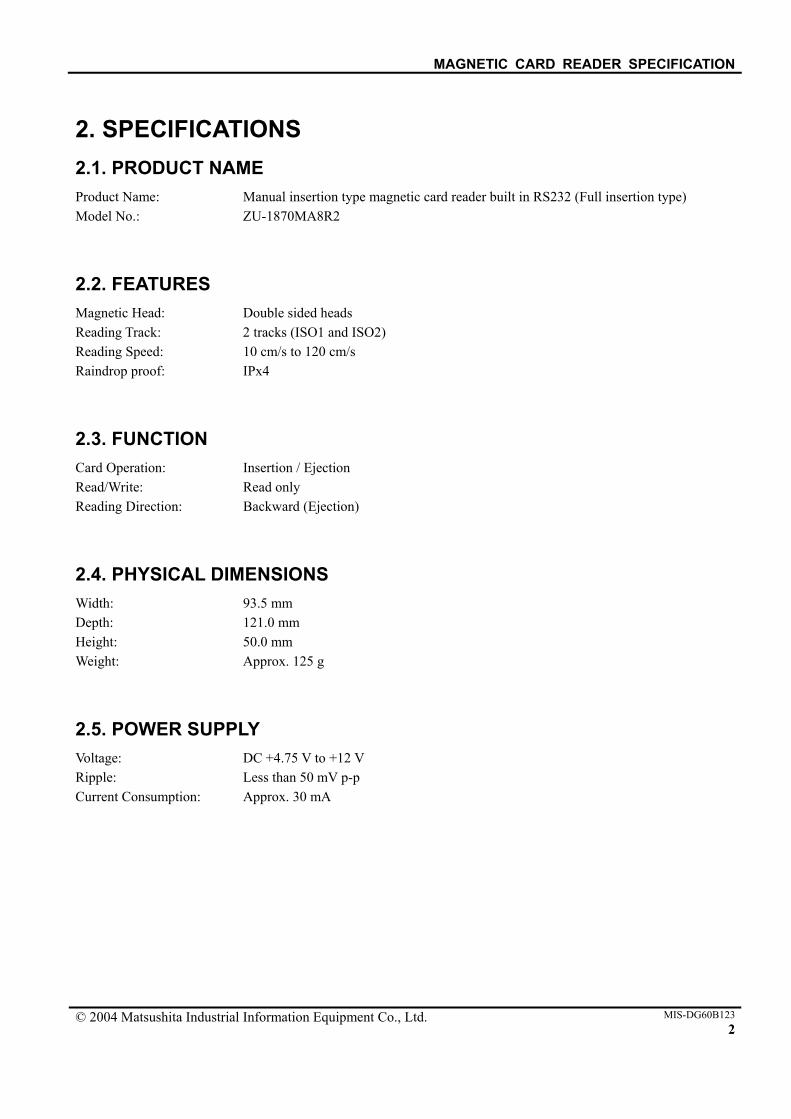
2. SPECIFICATIONS 2.1. PRODUCT NAME Product Name: Manual insertion type magnetic card reader built in RS232 (Full insertion type) Model No.: ZU-1870MA8R2
2.2. FEATURES Magnetic Head: Double sided heads Reading Track: 2 tracks (ISO1 and ISO2) Reading Speed: 10 cm/s to 120 cm/s Raindrop proof: IPx4
2.3. FUNCTION Card Operation: Insertion / Ejection Read/Write: Read only Reading Direction: Backward (Ejection)
2.4. PHYSICAL DIMENSIONS Width: 93.5 mm Depth: 121.0 mm Height: 50.0 mm Weight: Approx. 125 g
2.5. POWER SUPPLY Voltage: DC +4.75 V to +12 V Ripple: Less than 50 mV p-p Current Consumption: Approx. 30 mA

MAGNETIC CARD READER SPECIFICATION
© 2004 Matsushita Industrial Information Equipment Co., Ltd. MIS-DG60B1233
2.6. ENVIROMENTS Operating Temperature: -10 °C to +50 °C Operating Humidity: 10 % RH to 90 % RH (No condensation allowed) Storage Temperature: -20 °C to +60 °C Storage Humidity: 10 % RH to 95% RH (No condensation allowed) (24hours)
* Test procedure: Place the card reader in the standard environment (temperature: 20 °C ± 5 °C, humidity: 35 % RH to 60 % RH). Leave it for 12 hours, and measure the functions. Make sure no abnormality is found.
Vibration Sweep: 10 Hz/mm to 50 Hz/mm (X, Y, Z directions) Shock Durability: 294 m/s2 (30 G) Usage: Out door is available. Others: Make sure any source of noise that may deteriorate the characteristics of the card reader
is not present around the card reader.
2.7. LIFE AND RELIABILITY Magnetic Head: 500,000 times pass (2 passes / operation)
Note: The life is reliability number based on the result tested in a “clean office” environment. These numbers may be shortened dependent on the actual environment. Especially in a dusty environment*, even in the indoor application, dust or sand may shorten the life against the mechanical parts and most of the card transport mechanisms. In these cases, warranty of the card reader may be void unless the proper protection and countermeasures are performed by the terminal side. (In a clean office room. In damp or dirty atmosphere, the life may be 1/3 to 1/5 of the above figure.) *dusty environment: Refer to e.g. IEC 68, EN30721-3-3 class 3S2 or worse.

MAGNETIC CARD READER SPECIFICATION
© 2004 Matsushita Industrial Information Equipment Co., Ltd. MIS-DG60B1234
2.8. MAGNETIC STRIPE CARD STANDARD
2.8.1. PARAMTERS Card Specification:
2.8.2. PHYSICAL CHARACTERISTICS Thickness: 0.76 mm ± 0.08 mm Warpage: 2.5 mm max. (include relief height of embossed characters)
2.8.3. MAGNETIC CHARACTERISTICS Coercive Force (Hc): 2.4 × 10⁴ A/m to 2.4 × 10⁵ A/m Residual Flux (φr): 1.25 × 10⁻⁸ Wb/cm ± 0.15 × 10⁻⁸ Wb/cm Squareness Ratio(φr/φm): more than 0.70
Track Position Track 1 ISO1
Track 2 ISO2
Recording Method F2F F2F Recording Density 210 BPI 75 BPI Recording Capacity 79 characters
(7 bits) 40 characters
(5 bits)
MAGNETIC CARD READER SPECIFICATION
© 2004 Matsushita Industrial Information Equipment Co., Ltd. MIS-DG60B1235
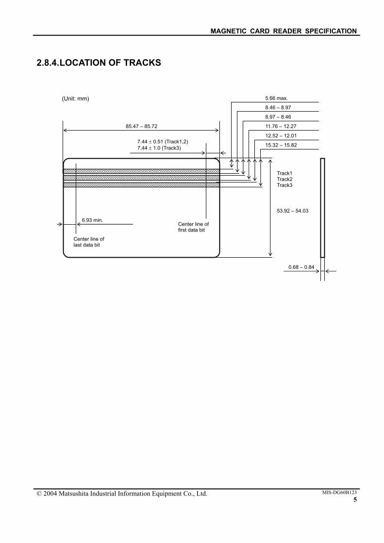
2.8.4. LOCATION OF TRACKS
15.32 – 15.82
12.52 – 12.01
11.76 – 12.27
8.97 – 8.46
8.46 – 8.97
5.66 max.
0.68 – 0.84
6.93 min.
85.47 – 85.72
53.92 – 54.03
Track1 Track2 Track3
7.44 ± 0.51 (Track1,2) 7.44 ± 1.0 (Track3)
Center line of last data bit
Center line of first data bit
(Unit: mm)
MAGNETIC CARD READER SPECIFICATION
© 2004 Matsushita Industrial Information Equipment Co., Ltd. MIS-DG60B1236
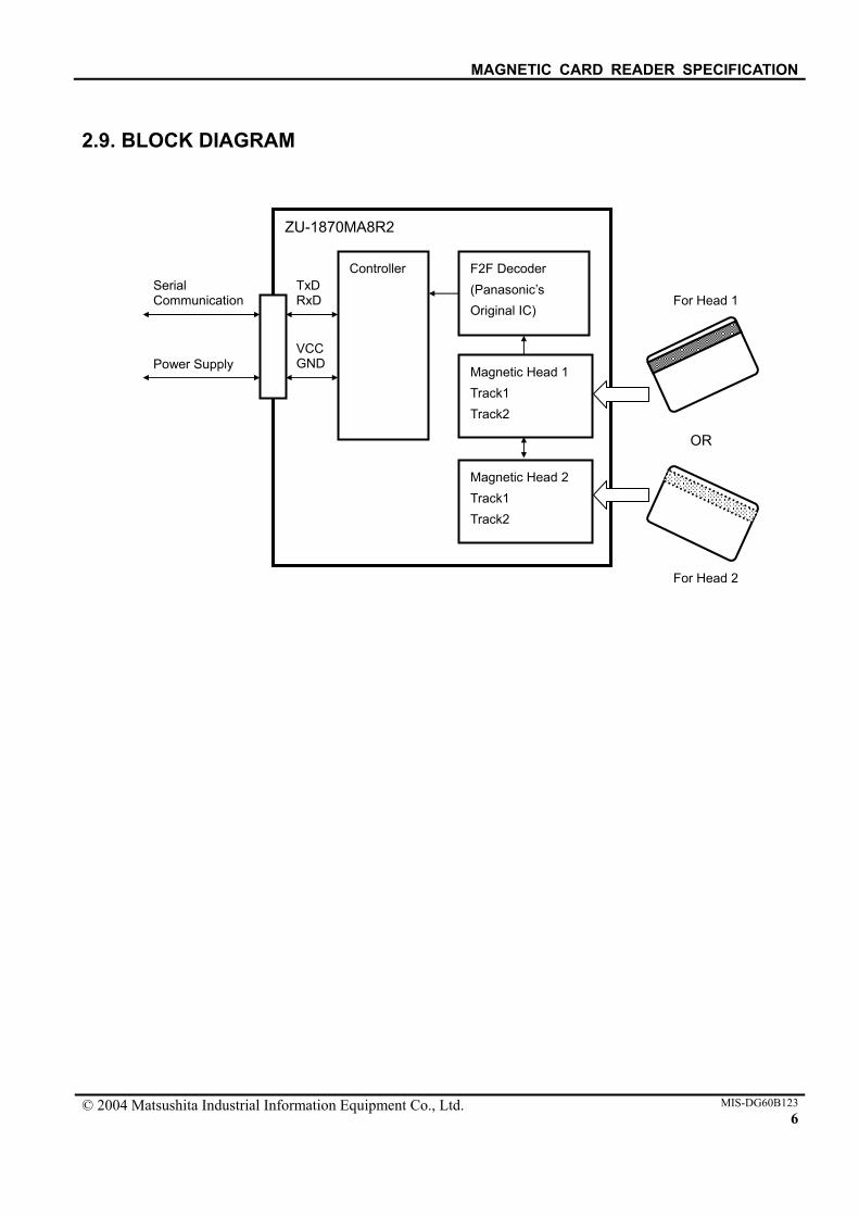
2.9. BLOCK DIAGRAM
ZU-1870MA8R2
Serial Communication
Power Supply
Controller F2F Decoder (Panasonic’s Original IC)
TxD RxD
VCC GND
Magnetic Head 1 Track1 Track2
Magnetic Head 2 Track1 Track2
OR
For Head 2
For Head 1
MAGNETIC CARD READER SPECIFICATION
© 2004 Matsushita Industrial Information Equipment Co., Ltd. MIS-DG60B1237
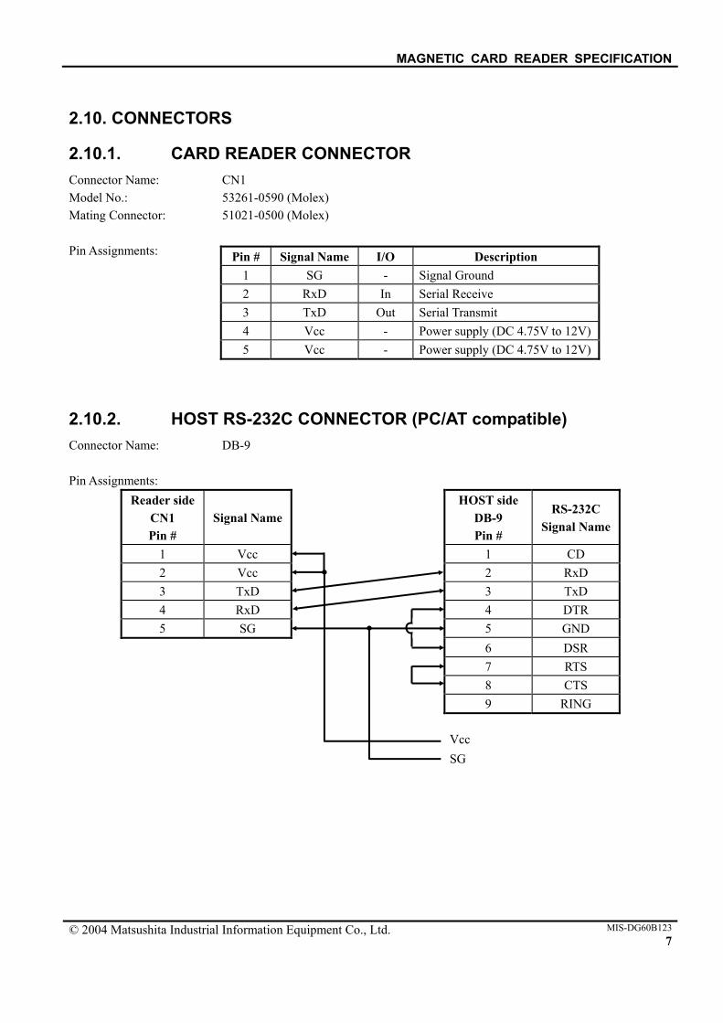
2.10. CONNECTORS
2.10.1. CARD READER CONNECTOR Connector Name: CN1 Model No.: 53261-0590 (Molex) Mating Connector: 51021-0500 (Molex) Pin Assignments:
2.10.2. HOST RS-232C CONNECTOR (PC/AT compatible) Connector Name: DB-9 Pin Assignments:
Reader side CN1 Pin #
Signal Name HOST side
DB-9 Pin #
RS-232C Signal Name
1 Vcc 1 CD 2 Vcc 2 RxD 3 TxD 3 TxD 4 RxD 4 DTR 5 SG 5 GND 6 DSR
7 RTS 8 CTS
9 RING
Pin # Signal Name I/O Description 1 SG - Signal Ground 2 RxD In Serial Receive 3 TxD Out Serial Transmit 4 Vcc - Power supply (DC 4.75V to 12V) 5 Vcc - Power supply (DC 4.75V to 12V)
Vcc SG
MAGNETIC CARD READER SPECIFICATION
© 2004 Matsushita Industrial Information Equipment Co., Ltd. MIS-DG60B1238
3. HOST PROTOCOL
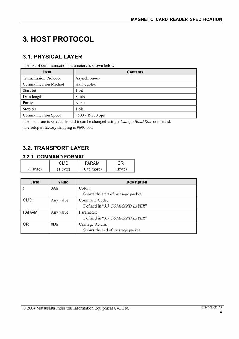
3.1. PHYSICAL LAYER The list of communication parameters is shown below:
Item Contents Transmission Protocol Asynchronous Communication Method Half-duplex Start bit 1 bit Data length 8 bits Parity None Stop bit 1 bit Communication Speed 9600 / 19200 bps The baud rate is selectable, and it can be changed using a Change Baud Rate command. The setup at factory shipping is 9600 bps.
3.2. TRANSPORT LAYER 3.2.1. COMMAND FORMAT
: (1 byte)
CMD (1 byte)
PARAM (0 to more)
CR (1byte)
Field Value Description
: 3Ah Colon; Shows the start of message packet.
CMD Any value Command Code; Defined in “3.3 COMMAND LAYER”
PARAM Any value Parameter; Defined in “3.3 COMMAND LAYER”
CR 0Dh Carriage Return; Shows the end of message packet.
MAGNETIC CARD READER SPECIFICATION
© 2004 Matsushita Industrial Information Equipment Co., Ltd. MIS-DG60B1239
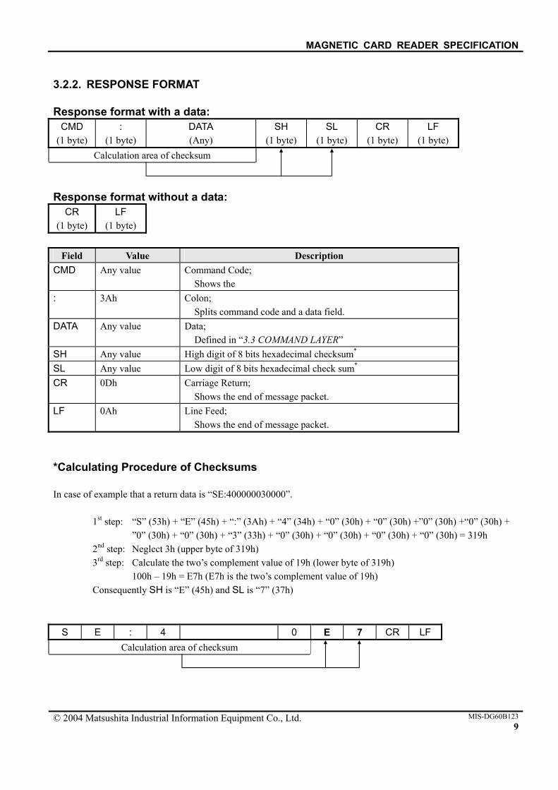
3.2.2. RESPONSE FORMAT Response format with a data:
CMD (1 byte)
: (1 byte)
DATA (Any)
SH (1 byte)
SL (1 byte)
CR (1 byte)
LF (1 byte)
Calculation area of checksum Response format without a data:
CR (1 byte)
LF (1 byte)
Field Value Description
CMD Any value Command Code; Shows the
: 3Ah Colon; Splits command code and a data field.
DATA Any value Data; Defined in “3.3 COMMAND LAYER”
SH Any value High digit of 8 bits hexadecimal checksum* SL Any value Low digit of 8 bits hexadecimal check sum* CR 0Dh Carriage Return;
Shows the end of message packet. LF 0Ah Line Feed;
Shows the end of message packet. *Calculating Procedure of Checksums In case of example that a return data is “SE:400000030000”. 1st step: “S” (53h) + “E” (45h) + “:” (3Ah) + “4” (34h) + “0” (30h) + “0” (30h) +”0” (30h) +“0” (30h) +
”0” (30h) + “0” (30h) + “3” (33h) + “0” (30h) + “0” (30h) + “0” (30h) + “0” (30h) = 319h 2nd step: Neglect 3h (upper byte of 319h) 3rd step: Calculate the two’s complement value of 19h (lower byte of 319h) 100h – 19h = E7h (E7h is the two’s complement value of 19h) Consequently SH is “E” (45h) and SL is “7” (37h)
S E : 4 0 E 7 CR LF Calculation area of checksum
MAGNETIC CARD READER SPECIFICATION
© 2004 Matsushita Industrial Information Equipment Co., Ltd. MIS-DG60B12310
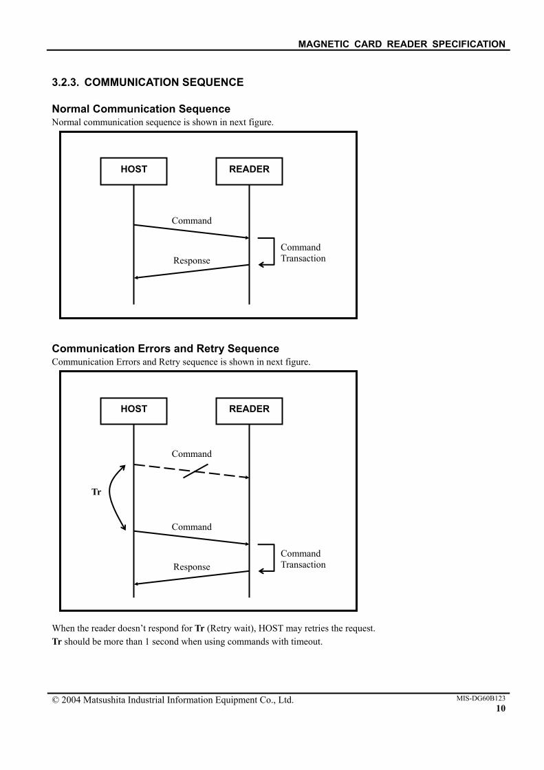
3.2.3. COMMUNICATION SEQUENCE Normal Communication Sequence Normal communication sequence is shown in next figure. Communication Errors and Retry Sequence Communication Errors and Retry sequence is shown in next figure. When the reader doesn’t respond for Tr (Retry wait), HOST may retries the request. Tr should be more than 1 second when using commands with timeout.
HOST READER
Command
Response Command Transaction
HOST READER
Command
Response Command Transaction
Command
Tr
MAGNETIC CARD READER SPECIFICATION
© 2004 Matsushita Industrial Information Equipment Co., Ltd. MIS-DG60B12311
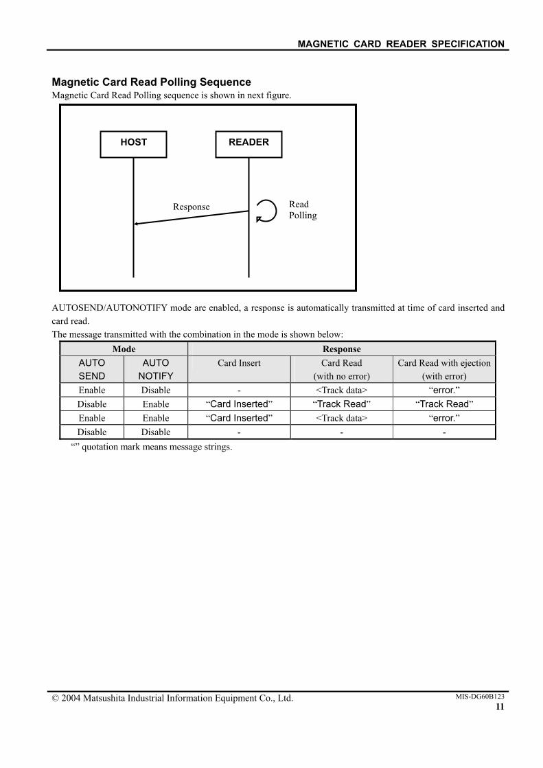
Magnetic Card Read Polling Sequence Magnetic Card Read Polling sequence is shown in next figure. AUTOSEND/AUTONOTIFY mode are enabled, a response is automatically transmitted at time of card inserted and card read. The message transmitted with the combination in the mode is shown below:
Mode Response AUTO SEND
AUTO NOTIFY
Card Insert Card Read (with no error)
Card Read with ejection(with error)
Enable Disable - <Track data> “error.” Disable Enable “Card Inserted” “Track Read” “Track Read” Enable Enable “Card Inserted” <Track data> “error.” Disable Disable - - -
“” quotation mark means message strings.
HOST READER
Response Read Polling

MAGNETIC CARD READER SPECIFICATION
© 2004 Matsushita Industrial Information Equipment Co., Ltd. MIS-DG60B12312
3.3. COMMAND LAYER
Classification Command Code Description Change Baud Rate B Sets the communication speed. Auto Clear
A Automatically clear track buffers after sending track data.
Auto Send S
Automatically send track data as soon as card has been swiped.
Configuration Commands
Auto Notify N
Automatically send the message as soon as card has been swiped.
Send Reader Status SR Sends the reader status, its configuration. Send Track Status ST Sends the track status.
Status Commands
Send Firmware Version V Sends the firmware version of the reader. Transmit Track Data T Transmits a data on track. Track Data
Commands Clear Track Data C Clears track buffers. Reader Commands
Reset Reader RX
Reset the reader.

MAGNETIC CARD READER SPECIFICATION
© 2004 Matsushita Industrial Information Equipment Co., Ltd. MIS-DG60B12313
3.3.1. CONFIGURATION COMMANDS All configurations set up by the configuration commands are saved at an EEPROM. After a power up the reader, all configurations are loaded form EEPROM. Change Baud Rate Description:
This command sets the serial I/O line baud rate. Command:
Bx
Where: x is the baud rate number. The specifies values are as follows:
Value Baud rate “3” (33h) 9600 bps (Setup at factory shipping) “4” (34h) 19200 bps
Response:
[CR][LF]
Note: The response is returned with the OLD baud rate. Example:
Command for set the serial I/O line baud rate is 19200bps: : B 4 [CR]
3Ah 42h 34h 0Dh

MAGNETIC CARD READER SPECIFICATION
© 2004 Matsushita Industrial Information Equipment Co., Ltd. MIS-DG60B12314
Auto Clear Description:
This command sets AUTOCLEAR bit. Command:
Ab
Where: b is the AUTOCLEAR bit. The specifies values are as following:
Value Auto Clear “0” (30h) Disable “1” (31h) Enable
Note: If AUTOCLEAR bit is enabled, the card reader will automatically clear track buffers after
sending track data. Then the Host will not be able to get track data again. If AUTOCLEAR bit is disabled, track data remain in buffer until track clear command is sent.
Response:
[CR][LF] Example:
Command for set the AUTOCLEAR bit is enabled: : A 1 [CR]
3Ah 41h 31h 0Dh
MAGNETIC CARD READER SPECIFICATION
© 2004 Matsushita Industrial Information Equipment Co., Ltd. MIS-DG60B12315
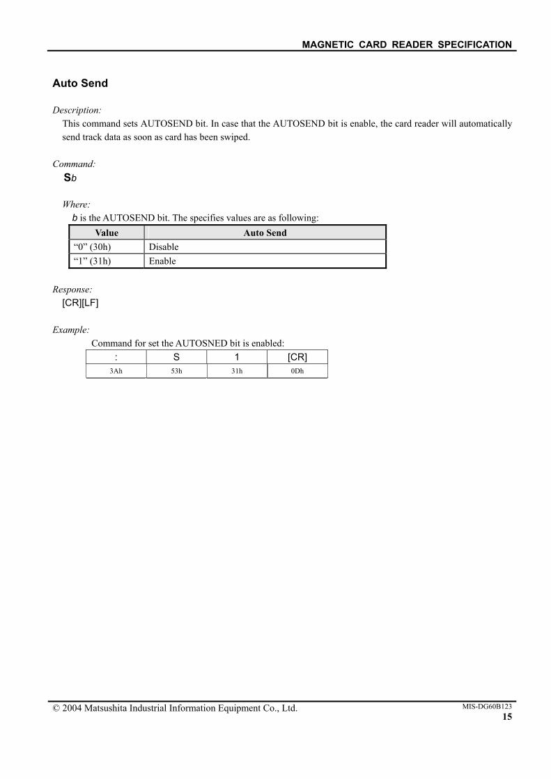
Auto Send Description:
This command sets AUTOSEND bit. In case that the AUTOSEND bit is enable, the card reader will automatically send track data as soon as card has been swiped.
Command:
Sb
Where: b is the AUTOSEND bit. The specifies values are as following:
Value Auto Send “0” (30h) Disable “1” (31h) Enable
Response:
[CR][LF] Example:
Command for set the AUTOSNED bit is enabled: : S 1 [CR]
3Ah 53h 31h 0Dh

MAGNETIC CARD READER SPECIFICATION
© 2004 Matsushita Industrial Information Equipment Co., Ltd. MIS-DG60B12316
Auto Notify Description:
This command sets AUTONOTIFY bit. Command:
Nb
Where: b is the AUTONOTIFY bit. The specifies values are as following:
Value Auto Notify “0” (30h) Disable “1” (31h) Enable
Note: If AUTONOTIFY bit is enabled and AUTOSEND bit is disabled, the card reader will send the
message “Card Inserted” as soon as card has been inserted and the message “Track Read” as soon as card has been read. See “3.2.3 COMMUNICATION SEQUENCE – Mag Card Read Polling Sequence”.
Response:
[CR][LF] Example:
Command for set the AUTONOTIFY bit is enabled: : N 1 [CR]
3Ah 4Eh 31h 0Dh
Response for the message as soon as card has been inserted: C a r d _ I n s e r t e d [CR] [LF]
43h 61h 72h 64h 20h 49h 6Eh 73h 65h 72h 74h 65h 64h 0Dh 0Ah
Response for the message as soon as card has been read:
T r a c k _ R e a d [CR] [LF] 54h 72h 61h 63h 6Bh 20h 52h 65h 61h 64h 0Dh 0Ah

MAGNETIC CARD READER SPECIFICATION
© 2004 Matsushita Industrial Information Equipment Co., Ltd. MIS-DG60B12317
3.3.2. STATUS COMMANDS Send Reader Status Description:
This command requests the reader to send the reader status, its configuration. Command:
SR
Response: SR:abci.scnde.xyz.t.[SH][SL][CR][LF]
Where:
The reader status is as following: Item Description Value
a Card Load 1 signal “0” (30h) = not detected
“1” (31h) = detected
b Card Load 2 signal “0” (30h) = not detected
“1” (31h) = detected
c Card Load 3 signal “0” (30h) = not detected
“1” (31h) = detected
i Card Inserted signal “0” (30h) = not detected
“1” (31h) = detected
s AUTOSEND bit “0” (30h) = disabled
“1” (31h) = enabled
c AUTOCLEAR bit “0” (30h) = disabled
“1” (31h) = enabled
n AUTONOTIFY bit “0” (30h) = disabled
“1” (31h) = enabled
d Track read direction “0” (30h) = forward
“1” (31h) = backward
e Start/End character including in track data “0” (30h) = not include
“1” (31h) = include
x Track #1 configuration “0” (30h) = disabled
“1” (31h) = enabled
y Track #2 configuration “0” (30h) = disabled
“1” (31h) = enabled
z Track #3 configuration “0” (30h) = disabled
“1” (31h) = enabled T Reader Type number “0” (30h) to “6” (36h)

MAGNETIC CARD READER SPECIFICATION
© 2004 Matsushita Industrial Information Equipment Co., Ltd. MIS-DG60B12318
Example:
Command for the reader status: : S R [CR]
3Ah 53h 52h 0Dh
Response for the reader status:
S R : 1 0 1 1 . 1 1 0 1 1 . 53h 52h 3Ah 31h 30h 31h 31h 2Eh 31h 31h 30h 31h 31h 2Eh
1 1 0 . 3 . E[SH] D[SL] [CR] [LF]31h 31h 30h 2Eh 33h 2Eh 45h 44h 0Dh 0Ah
Card Load1 signal = detected Card Load2 signal = not detected Card Load3 signal = detected Card Inserted signal = detected AUTOSEND bit = enabled AUTOCLEAR bit = enabled AUTONOTIFY bit = disabled Track read direction = backward Start/End character including in track data = enabled Track #1 configuration = enabled Track #2 configuration = enabled Track #3 configuration = disabled Reader Type number = 3: Half/Full insertion (1 sensor in back)
MAGNETIC CARD READER SPECIFICATION
© 2004 Matsushita Industrial Information Equipment Co., Ltd. MIS-DG60B12319
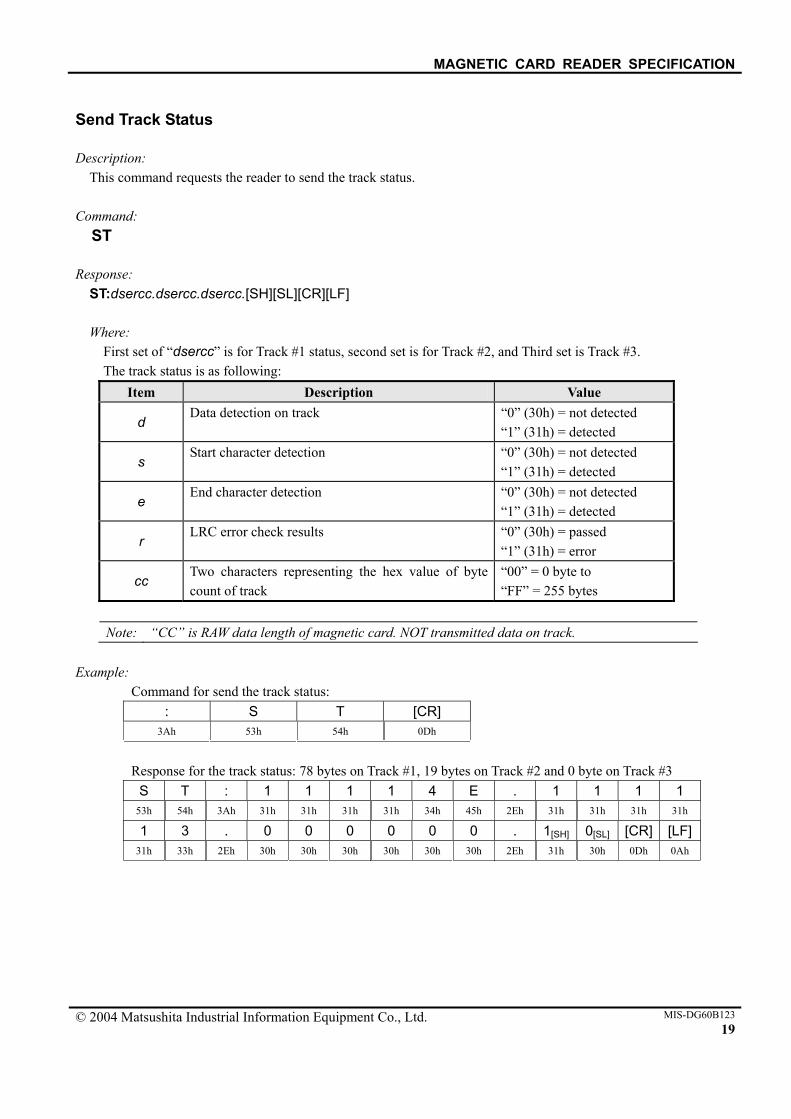
Send Track Status Description:
This command requests the reader to send the track status. Command:
ST
Response: ST:dsercc.dsercc.dsercc.[SH][SL][CR][LF]
Where:
First set of “dsercc” is for Track #1 status, second set is for Track #2, and Third set is Track #3. The track status is as following:
Item Description Value
d Data detection on track “0” (30h) = not detected
“1” (31h) = detected
s Start character detection “0” (30h) = not detected
“1” (31h) = detected
e End character detection “0” (30h) = not detected
“1” (31h) = detected
r LRC error check results “0” (30h) = passed
“1” (31h) = error
cc Two characters representing the hex value of byte count of track
“00” = 0 byte to “FF” = 255 bytes
Note: “CC” is RAW data length of magnetic card. NOT transmitted data on track.
Example:
Command for send the track status: : S T [CR]
3Ah 53h 54h 0Dh
Response for the track status: 78 bytes on Track #1, 19 bytes on Track #2 and 0 byte on Track #3
S T : 1 1 1 1 4 E . 1 1 1 1 53h 54h 3Ah 31h 31h 31h 31h 34h 45h 2Eh 31h 31h 31h 31h
1 3 . 0 0 0 0 0 0 . 1[SH] 0[SL] [CR] [LF]31h 33h 2Eh 30h 30h 30h 30h 30h 30h 2Eh 31h 30h 0Dh 0Ah

MAGNETIC CARD READER SPECIFICATION
© 2004 Matsushita Industrial Information Equipment Co., Ltd. MIS-DG60B12320
Send Firmware Version Description:
This command requests the reader to send the firmware version. Command:
V
Response: “Panasonic UCIMAG vx.xx Copyright yyyy[CR][LF]”
Where:
x.xx is firmware version. yyyy is year of copyrighted. Example:
Command for send firmware version of the reader: : V [CR]
3Ah 56h 0Dh
Response for firmware of the reader: The version is v3.10 in 1999-2004 copyrighted.
P A N A S O N I C _ U C I - M A 50h 41h 4Eh 41h 53h 4Fh 4Eh 49h 43h 20h 55h 43h 49h 2Dh 4Dh 41h
G _ v 3 . 1 0 _ C o p y r i g h 47h 20h 76h 33h 2Eh 31h 30h 20h 43h 6Fh 70h 79h 72h 69h 67h 68h
t _ 1 9 9 9 - 2 0 0 4 [CR] [LF] 74h 20h 31h 39h 39h 39h 2Dh 32h 30h 30h 34h 0Dh 0Ah
MAGNETIC CARD READER SPECIFICATION
© 2004 Matsushita Industrial Information Equipment Co., Ltd. MIS-DG60B12321
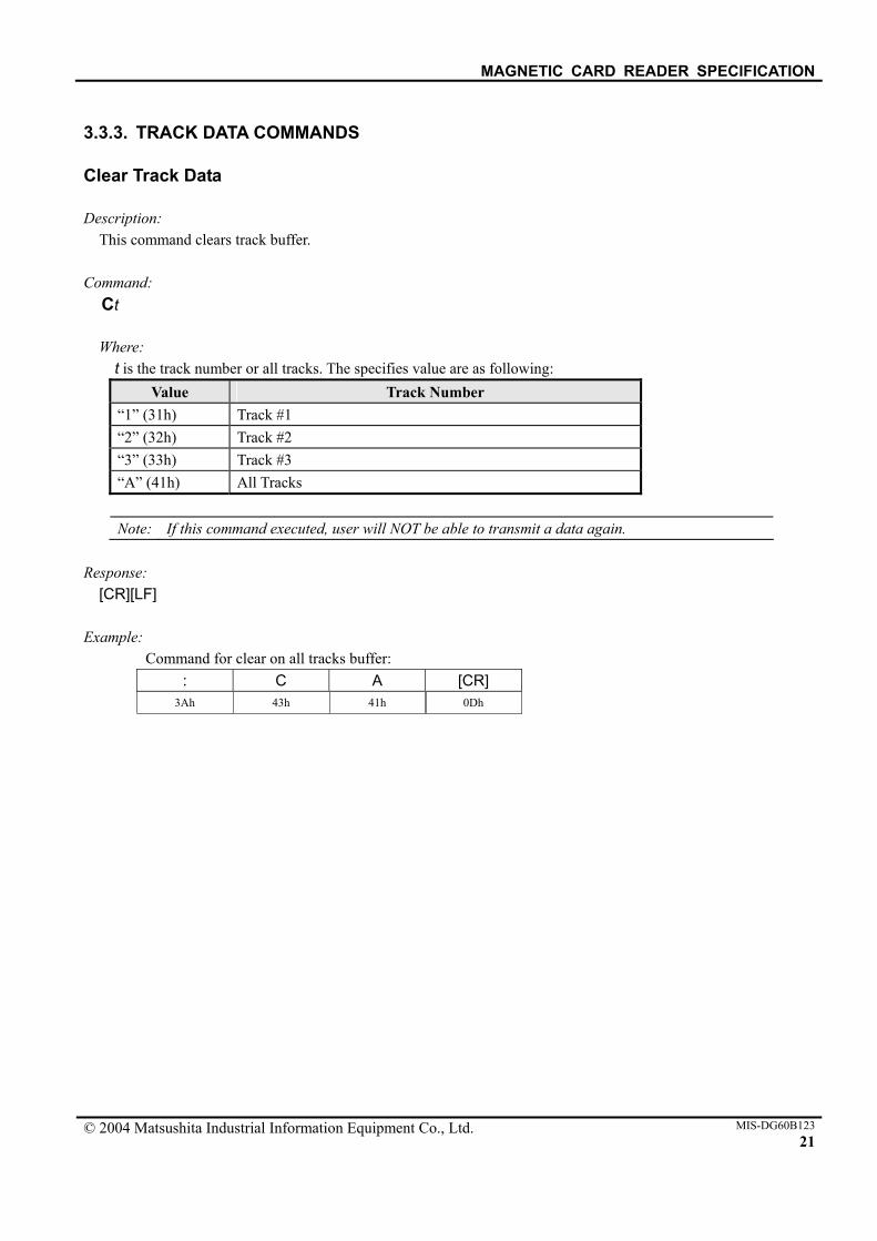
3.3.3. TRACK DATA COMMANDS Clear Track Data Description:
This command clears track buffer. Command:
Ct
Where: t is the track number or all tracks. The specifies value are as following:
Value Track Number “1” (31h) Track #1 “2” (32h) Track #2 “3” (33h) Track #3 “A” (41h) All Tracks
Note: If this command executed, user will NOT be able to transmit a data again.
Response:
[CR][LF] Example:
Command for clear on all tracks buffer: : C A [CR]
3Ah 43h 41h 0Dh

MAGNETIC CARD READER SPECIFICATION
© 2004 Matsushita Industrial Information Equipment Co., Ltd. MIS-DG60B12322
Transmit Track Data Description:
This command requests the reader to transmit the track data. Command:
Tt
Where: t is the track number or all tracks. The specifies value are as following:
Value Track Number “1” (31h) Track #1 “2” (32h) Track #2 “3” (33h) Track #3 “A” (41h) All Tracks (same as sending T1, T2 and T3 sequence)
Response:
Tt:data.[SH][SL][CR][LF]
Where: The track data is as following:
Item Description Value
t Track Number “1” (31h) = Track #1
“2” (32h) = Track #2 “3” (33h) = Track #3
data Data on track Any
Note: If there is an error in track data, a response is “Tn:error.[CR][LF]”. TA command is added [CR][LF] to the last of response data.
Example:
Command for transmit data on all tracks: : T A [CR]
3Ah 54h 41h 0Dh
Response for a data on all tracks:
T 1 : % Data on Track1 ? . [SH] [SL] [CR] [LF]54h 31h 3Ah 25h 3Fh 2Eh 0Dh 0Ah
T 2 : % Data on Track2 ? . [SH] [SL] [CR] [LF]54h 32h 3Ah 25h 3Fh 2Eh 0Dh 0Ah
T 3 : % Data on Track3 ? . [SH] [SL] [CR] [LF]54h 33h 3Ah 25h 3Fh 2Eh 0Dh 0Ah
[CR] [LF] 0Dh 0Ah
MAGNETIC CARD READER SPECIFICATION
© 2004 Matsushita Industrial Information Equipment Co., Ltd. MIS-DG60B12323
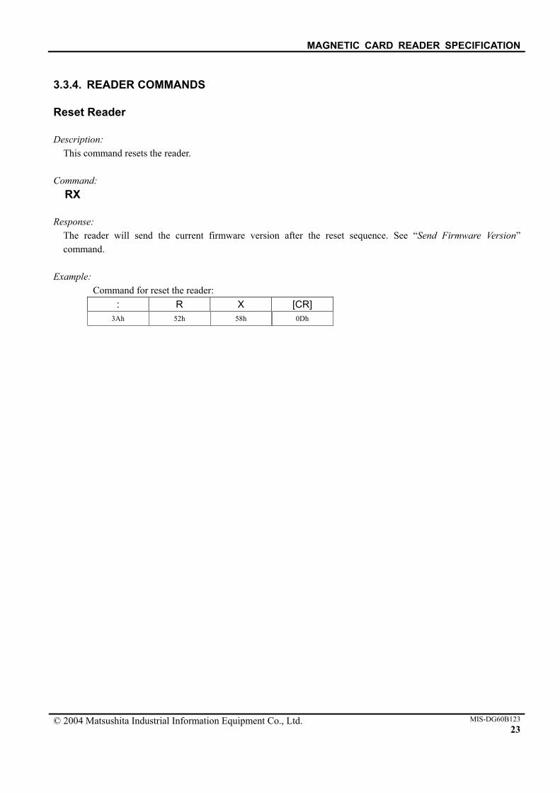
3.3.4. READER COMMANDS Reset Reader Description:
This command resets the reader. Command:
RX Response:
The reader will send the current firmware version after the reset sequence. See “Send Firmware Version” command.
Example:
Command for reset the reader: : R X [CR]
3Ah 52h 58h 0Dh
MAGNETIC CARD READER SPECIFICATION
© 2004 Matsushita Industrial Information Equipment Co., Ltd. MIS-DG60B12324
4. MAINTENANCE Because of difficulty in changing components on the Printed Circuits Board, replacement of whole unit is recommended for service and maintenance.
MAGNETIC CARD READER SPECIFICATION
© 2004 Matsushita Industrial Information Equipment Co., Ltd. MIS-DG60B123 25
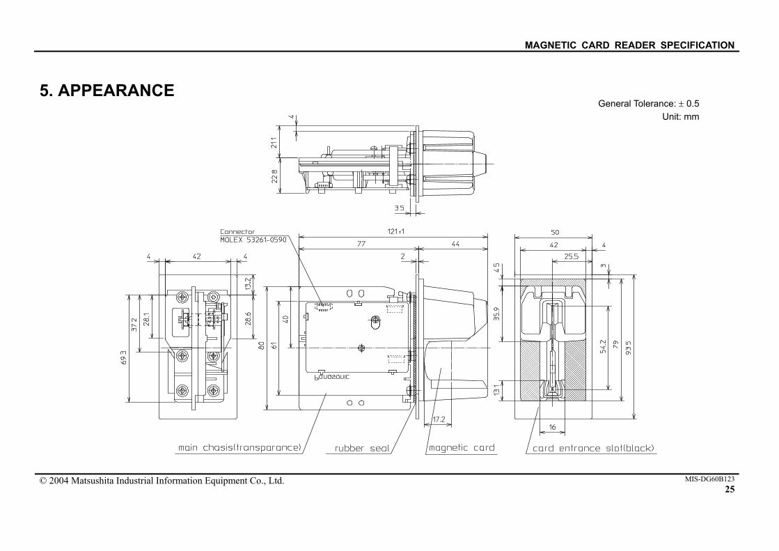
5. APPEARANCE General Tolerance: ± 0.5
Unit: mm

MAGNETIC CARD READER SPECIFICATION
© 2004 Matsushita Industrial Information Equipment Co., Ltd. MIS-DG60B12326
The product label with which the manufacturing number was printed is stuck on the reader module.
ZU-1870MA8R247
Manufacturing Month: 1 = January
: 9 = September O = October N = November D = December
Manufacturing Year:
The last digit of the Christian era