specification manual: ultra finn · the ultra finntm requires 5.0 volts dc. current is typically 17...
TRANSCRIPT

Ultra FINNTM Specification Manual
Table of Contents
Information in this document is provided in connection with the Ultra FINNTM product. FINN Test Electronics (FTE) shall not be liable for errors or damages sustained in connection with the delivery, use or performance of this document and the information contained herein. Provision of this document does not in any way constitute recommendation of product fitness for a specific purpose. In future publications, FTE may make changes to specifications and product descriptions at any time, without notice. Contact FTE or your distributor to obtain the latest specifications prior to placing your product order.
U. S. Patent Nos: 6,490,037; 7,023,554; 7,227,639 and 7,265,822. Additional patents pending.
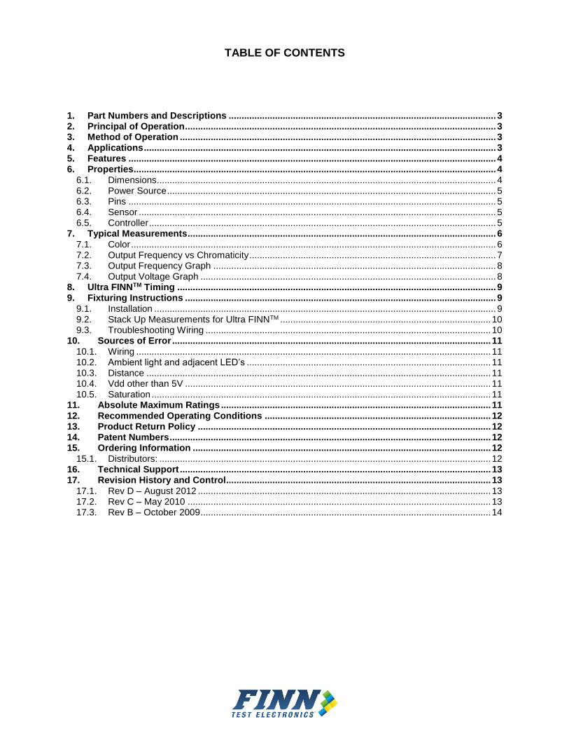
TABLE OF CONTENTS
1. Part Numbers and Descriptions ........................................................................................................ 3 2. Principal of Operation ......................................................................................................................... 3 3. Method of Operation ........................................................................................................................... 3 4. Applications ......................................................................................................................................... 3 5. Features ............................................................................................................................................... 4 6. Properties ............................................................................................................................................. 4
6.1. Dimensions .................................................................................................................................... 4 6.2. Power Source ................................................................................................................................ 5 6.3. Pins ............................................................................................................................................... 5 6.4. Sensor ........................................................................................................................................... 5 6.5. Controller ....................................................................................................................................... 5
7. Typical Measurements ........................................................................................................................ 6 7.1. Color .............................................................................................................................................. 6 7.2. Output Frequency vs Chromaticity ................................................................................................ 7 7.3. Output Frequency Graph .............................................................................................................. 8 7.4. Output Voltage Graph ................................................................................................................... 8
8. Ultra FINNTM Timing ............................................................................................................................ 9 9. Fixturing Instructions ......................................................................................................................... 9
9.1. Installation ..................................................................................................................................... 9 9.2. Stack Up Measurements for Ultra FINNTM .................................................................................. 10 9.3. Troubleshooting Wiring ............................................................................................................... 10
10. Sources of Error ............................................................................................................................ 11 10.1. Wiring .......................................................................................................................................... 11 10.2. Ambient light and adjacent LED’s ............................................................................................... 11 10.3. Distance ...................................................................................................................................... 11 10.4. Vdd other than 5V ....................................................................................................................... 11 10.5. Saturation .................................................................................................................................... 11
11. Absolute Maximum Ratings ......................................................................................................... 11 12. Recommended Operating Conditions ........................................................................................ 12 13. Product Return Policy .................................................................................................................. 12 14. Patent Numbers ............................................................................................................................. 12 15. Ordering Information .................................................................................................................... 12
15.1. Distributors: ................................................................................................................................. 12 16. Technical Support ......................................................................................................................... 13 17. Revision History and Control ....................................................................................................... 13
17.1. Rev D – August 2012 .................................................................................................................. 13 17.2. Rev C – May 2010 ...................................................................................................................... 13 17.3. Rev B – October 2009 ................................................................................................................. 14

Rev D -012516
3
1. Part Numbers and Descriptions
TCUF102SL TCUF102
Part Number Description TCUF102SL Ultra FINNTM with Sleeve TCUF102 Ultra FINNTM sensor
2. Principal of Operation
The Ultra FINNTM combines a custom packaged, four-band color sensor with a microprocessor to optimize all the functions necessary to precisely distinguish the color and intensity of a light source or LED. The Ultra FINNTM accurately takes measurements from the sensor, calculates the color and strength of the light being tested, and converts it to an easy to read signal for comparing LEDs and other light sources.
3. Method of Operation
The small, slim packaging of the Ultra FINNTM allows for easy installation directly in front or on top of the LED on a printed circuit board. During test, the light source (LED) is activated and the Ultra FINNTM outputs a frequency in kHz that quantifies the LED’s color. The same signal quantifies the brightness of the LED with its pulse-width (average DC voltage). Now, engineers can use anything from simple stand-alone meters to fully integrated equipment in their automated test to implement a quality controlled, extremely reliable method for the test and measurement of light sources, a.k.a. LEDs.
4. Applications
Automates testing of LEDs for placement, color and brightness
Used for Functional and In-circuit testing, on any test platform
Quality control for characterizing and standardizing LED use

Rev D -012516
4
5. Features
Detects 2000 different hues between Blue (380 nm) and Red (700 nm)
Increased repeatability and reliability
Tests most LEDs in less than 10 milliseconds
Mini package is more than 8 times smaller than the Smart FINN®
Eliminates the need for light pipes in almost all applications
Durable package and sleeve protects parts from potential damage during handling
Covers complete visible spectrum, plus Ultraviolet and Infrared
Operating voltage of 5.0Vdc
Color identification determined by the frequency output and intensity indicated by the DC average of the same output (patented feature)
Works with most types of LEDs on the market today – bright or dim, diffused or non-diffused, and smd or through-hole
Can identify different types of multichromatic light (such as white, magenta, and purple)
Fully automated testing
Custom sleeve allows for easy installation – just drill, press fit, and wire wrap
6. Properties
6.1. Dimensions

5
6.2. Power Source
The Ultra FINNTM requires 5.0 volts DC. Current is typically 17 mA.
6.3. Pins
Three pins are: Output (signal), Ground, and Power Pins are spaced 70 mil apart Sleeve uses standard 16 mil square posts for wire wrapping, 30 gauge wire is recommended. Smaller gauge or thicker wire may cause undue stress on the wire wrap posts.
6.4. Sensor
Light- to- frequency converter sensor comprised of an 8 x 8 array of photodiodes, 16 photo-diodes each of blue, green and red filters and 16 photo-diodes of clear, with no filter.
6.5. Controller
The micro controller in combination with the precision MHz high frequency clock source allows for extremely fast and accurate sampling of the light source under test.

6
7. Typical Measurements
7.1. Color
Typical Measurements
Color nm kHz
Red 635 12.42
Amber 608 11.25
Yellow 585 9.70
Green 565 8.25
Pure Green 525 7.21
Blue 470 5.90
Other Measurements
Infrared Up to 700 12.5 - 13.1
Ultraviolet Down to 400 3.5 - 3.95
Fluorescent multiple 4.2
White (red dominant)
multiple 4.0 - 4.35
White (blue dominant)
multiple 4.4 - 5.0
Saturation n/a 1.8 to 2.3
Dark n/a 0.998
7
7.2. Output Frequency vs Chromaticity
8
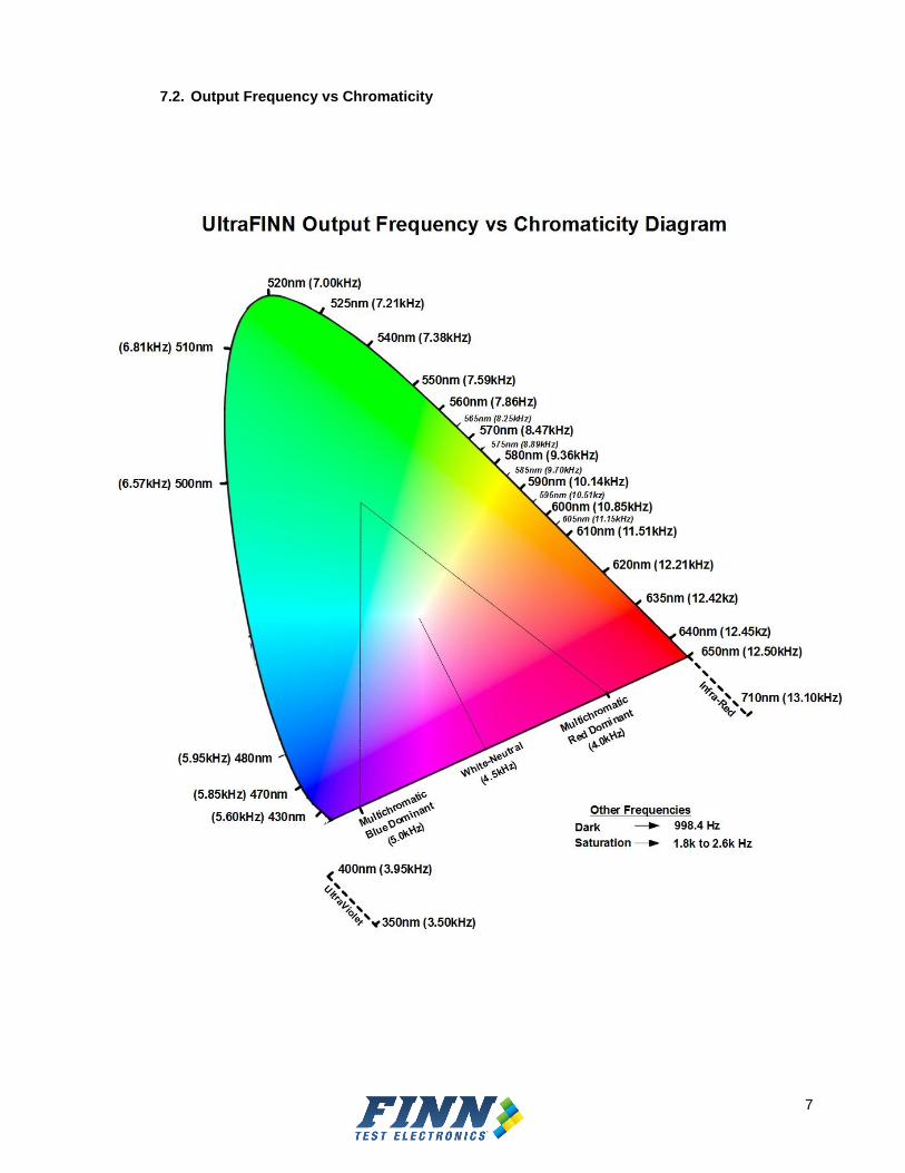
7.3. Output Frequency Graph
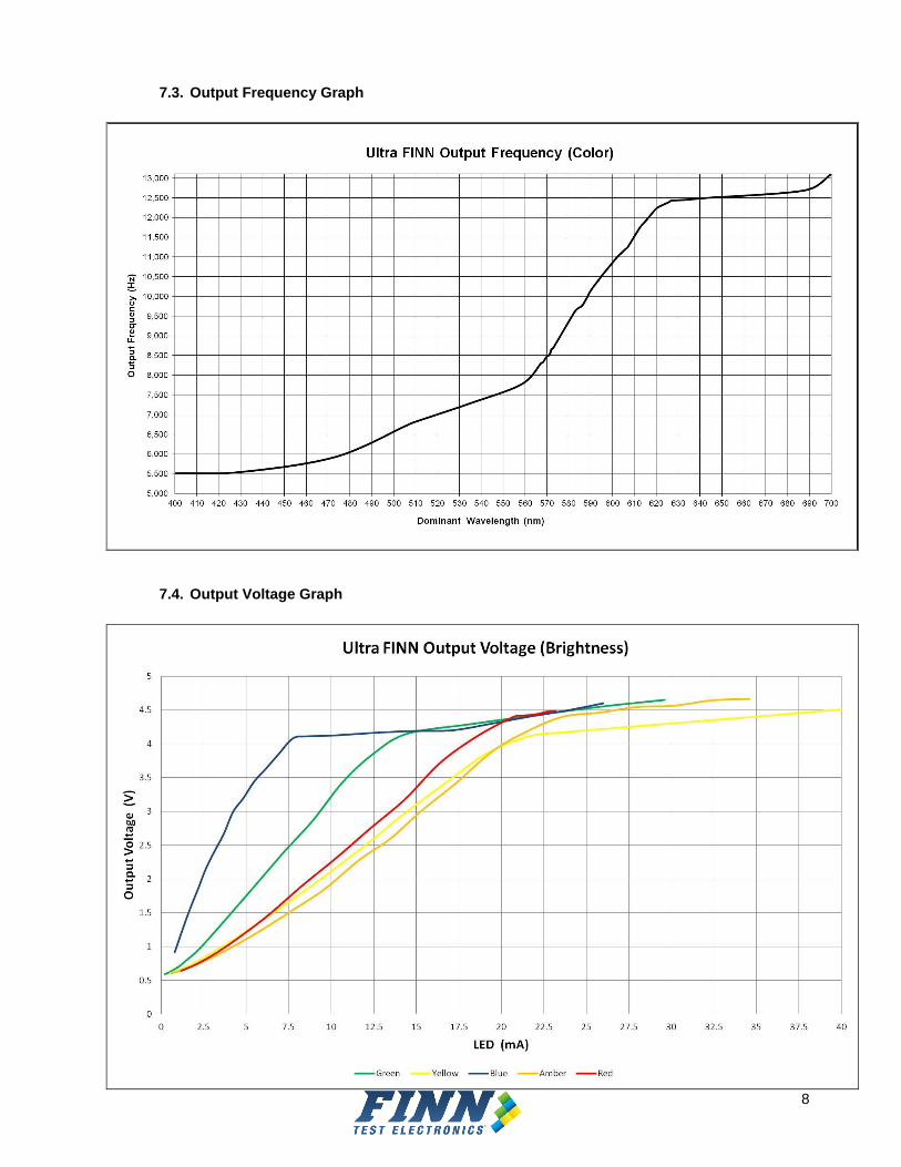
7.4. Output Voltage Graph

9
8. Ultra FINNTM Timing
UltraFINNTM response is typically less than 10 milliseconds. The response time will decrease for brighter LEDs and will increase for dimmer LEDs.
9. Fixturing Instructions
The Ultra FINNTM sleeve is easy to insert into most of the materials used in fixturing today.
9.1. Installation

10
9.2. Stack Up Measurements for Ultra FINNTM
9.3. Troubleshooting Wiring

11
10. Sources of Error
10.1. Wiring
Special care should be paid to the wiring instructions in section 9.1. Improper wiring will result in over-heating and damage to the part. If miss-wiring has occurred, immediate replacement of the damaged part is recommended.
10.2. Ambient light and adjacent LED’s
Light from sources other than the device being tested should be prevented from reaching the sensor surface while making measurements. Ambient light entering the sensor’s active area will be used to calculate the color and intensity. Typically the ambient light is many orders of magnitude less than the LED and ambient light will have little effect. If the ambient light is significant be sure eliminate the ambient light by using a shroud or heat shrink tubing.
10.3. Distance
The further away the sensor is from the LED, the lower the voltage response of the sensor. If the LED is dim (20mcd or less), the sensor face should be around 0.10” to 0.15” from the LED. LED’s that are medium brightness (20-100mcd) can have a greater distance 0.15” to 0.25”. And very bright LED’s (100-200mcd) should be 0.25” or greater for best results. If using light pipes or light conduit this distance should be measured from the LED lens to the front face of the light pipe with a small gap between sensor and other end of conduit.
10.4. Vdd other than 5V
The UltraFINNTM will not turn on if the supply voltage is lower than 4.70Vdc. Make sure the supply voltage at the UltraFINNTM wire wrap tail is greater than 4.70Vdc, but no more than 5.50V.
10.5. Saturation
If the output frequency is between 1.8 kHz and to 2.3 kHz the sensor is in saturation. Reduce the intensity of the LED if possible. Another way to get out of saturation is to move the sensor further from the LED or switch to a smaller diameter light conduit.
11. Absolute Maximum Ratings
Over operating free-air temperature range (unless otherwise noted)†
Supply voltage, VDD (see Note 1) 6 V
Operating free-air temperature range, TA 0C to 70C
Storage temperature range –25C to 85C
Maximum current or output ±40 mA
† Stresses beyond those listed under “absolute maximum ratings” may cause permanent damage to the device. These are stress ratings only, and functional operation of the device at these or any other conditions beyond those indicated under “recommended operating conditions” is not implied. Exposure to absolute-maximum-rated conditions for extended periods may affect device reliability. NOTE 1: All voltage values are with respect to GND lead.

12
12. Recommended Operating Conditions
Min Nom Max Unit
Supply voltage, VDD 2.7 5.0 5.5 V
Operating free-air temperature range, TA 0 25 70 Celsius
Supply current - 17 40 (Note1) mA
Note1: Additional loads on output pin not included
13. Product Return Policy
All products are inspected and fully tested prior to leaving the FINN Test Electronics facility. If it is believed that a product was shipped damaged, the damaged parts must be shipped back to Test Coach for evaluation. Once received and evaluated, FINN Test Electronics will replace the item in an even part for part exchange only
Any discrepancies in your order must be reported immediately. FINN Test Electronics offers a thirty (30) day return/exchange policy on products that have been misordered. The thirty day time limit is determined from the date of purchase. Damaged, used or altered goods will not be accepted for credit or exchange.
Please contact FINN Test Electronics for an RMA number before returning any product to FINN Test Electronics. Returns sent without an RMA number will not be accepted. Please see our Warranty and Return Policy document for a full explanation of our warranty and the appropriate return procedures.
14. Patent Numbers
U.S. Patent Nos. 6,490,037 - 7,023,554 - 7,227,639 - 7,265,822 Additional patents pending
15. Ordering Information
FINNTM parts may be ordered directly by calling 224-662-0383 or emailing to [email protected]. Customers located outside of the US who would prefer to place an order locally may contact one of the FINNTM distributors listed below.
15.1. Distributors:
France – Cotelec - www.cotelec.fr Germany – Fixtest GmbH - www.fixtest.de Japan - Newly Tsuchiyama Co., Ltd. - www.newly-t.com Switzerland – SQC AG – www.sqc.ch Distributor phone numbers and addresses may be accessed by clicking on the Distributor List located on the Contact US page at www.FINNTestElectronics.com.

13
16. Technical Support
Our product engineers are available to assist you with choosing the correct FINNTM product to fit your specific needs as well as to answer any technical questions you may have regarding installation and/or implementation.
Please contact us at: Email: [email protected] Phone: 224-662-0383
17. Revision History and Control
17.1. Rev D – August 2012
Incorporating customer feedback, Rev D is now faster, more accurate, and easier to use. To ensure compatibility with Rev Cx the following features have not changed:
The output Frequencies (color readings) did NOT change from Rev Cx to Rev D0.
The output Pulse width (intensity) did NOT change from Rev Cx to Rev D0.
The Rev D hardware has the same dimensions and is compatible with all revision sleeves and existing sockets. The following improvements will be seen when utilizing Rev D0.
The typical current consumption was reduced from 25mA to 17mA (Rev D0).
New sampling algorithms allow the UltraFINNTM to return a more accurate reading even when the LED is slow to stabilize.
The new revision accurately measures LEDs driven by pulsed signals with frequencies greater than 500Hz without sacrificing performance for steady state (near DC) applications.
Required delays for measurements can be reduced without sacrificing accuracy. Typical measurement delays will be less than 10msec from LED turn-on time.
On Agilent projects the Cpk* are expected to be over 50.
Extremely dim LED’s can be tested more accurately. The Ultra FINNTM have the following revision marking on the black molding: “D0”. *Cpk is a gauge of measurement repeatability. Typically, a reading of 10 or greater is considered highly reliable.
17.2. Rev C – May 2010
Due to a change in process some of the characteristics for the Ultra FINNTM have changed. The following sections give details on the changes.
We are introducing a new Sleeve which uses a 0.016” square posts which are more robust than the old 0.025” square post. The 0.016” square posts are 0.050” shorter than the old Sleeve which reduces the amount of clearance needed to install the Sleeve.
We now recommend that distance from the LED to the sensor face is ~0.300”.
The new sensor also incorporates an Infra Red cut filter which reduces IR effects on the readings.

14
The surface area of the new sensor is slightly smaller. To compensate for this, the sensor now includes a diffuser which helps when reading non-diffused LEDs. Another benefit of the diffuser is that the sensor now can measure brighter LEDs without saturating.
Ambient light from the sides is reduced because the new process has more dark blocking material around the sensor.
Although the frequency response has changed slightly, the ability of discriminating color is superior to the old revision Ultra FINNs.
The Ultra FINNTM have the following revision marking on the black molding: “C0”. Below is a chart that highlights the differences in responses from Rev A/B to RevC. Similar information in found in the graph in Appendix A. To adjust test limits, re-center the limits around the RevC responses.
Typical Measurements
Color nm Ultra FINN Rev A/B
(kHz)
Ultra FINN Rev C (kHz)
Red 650 12.50 12.5
Red 635 12.39 12.42 Amber 608 11.56 11.25 Yellow 585 9.21 9.70 Green 565 7.64 8.25 Pure Green 525 6.54 7.21
Blue 470 5.80 5.90
Other Measurements
Infrared Up to 750 12.5-13.1 12.5 – 13.1
Infrared 750 to 950 12.6-13.1 invalid Ultraviolet Down to 380 3.5-3.95 3.5 – 3.95
Fluorescent multiple 4.2 4.2
White(red dominant) multiple 4.0-4.35 4.0 -4.5
White(blue dominant) multiple 4.4-5.0 4.5 – 5.0
Saturation n/a 1.8 to 2.6 1.8 to 2.6
Dark n/a 0.998 0.998
17.3. Rev B – October 2009
Effective October 26, 2009 the firmware for the Ultra FINNTM has been updated to reflect the following changes:
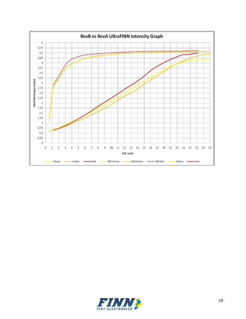
1. Improved intensity readings (output voltages) for all colors LEDs. The output voltage is now linear. Below are some graphs which show the differences in the output voltages between the Rev A Ultra FINNTM and the new Rev B Ultra FINNTM.
2. Improved differentiation between blue LEDs. A slight reduction in frequency of blue LEDs may be noticed with the new firmware.
These Ultra FINNs are marked on the black molding as: “B1”.

15
16