specification no. ti/spc/psi/isoltr/0130 ministry of...
TRANSCRIPT

DRAFT SPECIFICATION No. TI/SPC/PSI/ISOLTR/0130
RESEARCH DESIGNS AND STANDARDS ORGANISATION
Effective
From 21.03.2013
TECHNICAL SPECIFICATION for
25kV/72.5KV/123KV/145KV/245KV ac Single Pole , Double Pole & Triple Pole
Motorized/ Manual OPERATED ISOLATORS
FOR RAILWAYS ac TRACTION SUB-STATIONS
Page
1 of 51
SPECIFICATION No. TI/SPC/PSI/ISOLTR/0130
GOVERNMENT OF INDIA
MINISTRY OF RAILWAYS
Technical Specification
for
i. 25KV ii. 66KV iii. 123KV
iv. 145KV v. 245 KV
Motorized/Manual operated Isolators
For Railway Electric Traction
RESEARCH DESIGNS AND STANDARDS ORGANIZATION
GOVERNMENT OF INDIA
MINISTRY OF RAILWAYS
LUCKNOW - 226 01

DRAFT SPECIFICATION No. TI/SPC/PSI/ISOLTR/0130
RESEARCH DESIGNS AND STANDARDS ORGANISATION
Effective
From 21.03.2013
TECHNICAL SPECIFICATION for
25kV/72.5KV/123KV/145KV/245KV ac Single Pole , Double Pole & Triple Pole
Motorized/ Manual OPERATED ISOLATORS
FOR RAILWAYS ac TRACTION SUB-STATIONS
Page
2 of 51
INDEX
Clause Description
1.0 Scope
2.0 Climatic, Environmental & operating condition
3.0 List of related specifications
4.0 Rating, name plate details and other information
5.0 Design and constructional features
6.0 Locking
7.0 Earth contact assembly
8.0 Arcing horn
9.0.9.1,9.2,9.3 Motor, Gear, Space heater, Terminal bock and Wiring
10.0 Test
11.0 Test Method
12.0 Revalidation of type tests
13.0 Bulk Manufacturing
14.0 Technical data and drawing
15.0 Installation, Testing and Commissioning
16.0 Clause wise conformity, deviations etc.
17.0 Warranty
18.0 Training of Indian Railway’s engineers
19.0
Packing and Dispatch
Annexure-A SCHEDULE OF GUARANTED PERFORMNCE DATA
TECHNICAL AND OTHER PARTICULARS FOR ISOLAOR.
Annexure-B following information shall be furnished by the manufacturer /supplier:
Annexure-C Definition
Annexure-D General arrangement of motorized isolator

DRAFT SPECIFICATION No. TI/SPC/PSI/ISOLTR/0130
RESEARCH DESIGNS AND STANDARDS ORGANISATION
Effective
From 21.03.2013
TECHNICAL SPECIFICATION for
25kV/72.5KV/123KV/145KV/245KV ac Single Pole , Double Pole & Triple Pole
Motorized/ Manual OPERATED ISOLATORS
FOR RAILWAYS ac TRACTION SUB-STATIONS
Page
3 of 51
1. SCOPE
1.1 This specification applies to single pole double pole & triple pole
motorized/manual operated isolators with earthling switch/without earthling
switch as specified by purchases in the particular tender for outdoor use in
25kV ac 50 Hz single phase/2x25kV AT Feeding System for overhead
equipment (OHE), Traction Substations and Switching Stations. The
Specification also applies to the operating mechanism of the Isolator and
Earthling Switch. The Isolator shall be mounted on a mast/structure as
required. The operation of isolators and supply of battery charger through a
two core cable shall be possible from a remote location at more than 500 m
.The status of isolators i.e. whether Close or Open shall be available at the
station master chamber. This Specification supersedes following Specification:-
Sl.No Specification No. Description
1. ETI/PSI/41(1/73) 110kV,Double Pole and Triple Pole Isolators
2. ETI/PSI/20(2/73) 132kV,Double Pole and Triple Pole Isolators
3. ETI/PSI/20A(6/79) 132kV,Earthing Blade Assembly for Double
Pole and Triple Pole Isolators
4. ETI/PSI/20B(7/79) 132kv,Double Pole and Triple Pole Motor
Operated Isolators
5. ETI/PSI/50(8/79) 66kV,Double Pole and Triple Pole Isolators
6. ETI/PSI/50A(8/79) 66kV,Double Pole and Triple Pole Isolators
7. ETI/PSI/50B(4/80) 66kV,Double Pole and Triple Pole Motor
Operated Isolators
8. ETI/PSI/88(4/87) 220kV,Double Pole and Triple Pole Isolators
9. ETI/PSI/122(3/89) 245kV/145kV/123kV/72.5kV Double Pole
and Triple Pole Isolators
10. ETI/PSI/133(8/89) 25kV,ac Double Isolators for 2x25kV AT
Feeding System

DRAFT SPECIFICATION No. TI/SPC/PSI/ISOLTR/0130
RESEARCH DESIGNS AND STANDARDS ORGANISATION
Effective
From 21.03.2013
TECHNICAL SPECIFICATION for
25kV/72.5KV/123KV/145KV/245KV ac Single Pole , Double Pole & Triple Pole
Motorized/ Manual OPERATED ISOLATORS
FOR RAILWAYS ac TRACTION SUB-STATIONS
Page
4 of 51
11. ETI/OHE/16(1/94) 25kV,ac Single Pole and Double Pole
Isolators
12. TI/SPC/PSI/ISOLTR/1060.
25kV,ac Single Pole and Double Pole
Motorized Isolators
1.2 Scope of supply
The isolator shall be complete with all parts, fittings and accessories including mounting frame work, insulators, operating rod, operating mechanism box, battery, battery charger remote control box along with OPEN/CLOSE
indication, cable size, insulators, motor operating mechanism and battery and charger necessary for its efficient operation. All such parts, fittings and
accessories except cables shall be deemed to be within the scope of this specification, whether specifically mentioned or not. The isolator, single, double and triple pole, shall be supplied fully assembled on a suitable rigid
frame. For double/triple pole isolators, the cross channels for mounting, shall also form part of supply and for type 1 A (SP) 24V, 40AH, battery& battery
charger shall also part of supply. 1.3 The earthling switch (wherever provided) shall be of the manually operated
type, complete with all parts, fittings and accessories including mounting attachment, operating rod/operating mechanism box etc. necessary for their
efficient operation.
2.0 Climatic, Environmental & operating condition 2.1 The isolator is intended to be used as outdoor line sectioning switches .the
isolator shall be used in normally polluted atmosphere, subject to dust, smoke and effluents from chemical plants. It may also be used in coastal areas.
2.2 Environmental Conditions
S. No
Parameters Value
1. Maximum ambient air temperature
550 C
2. Minimum temperature of air in shade
-5 0 C

DRAFT SPECIFICATION No. TI/SPC/PSI/ISOLTR/0130
RESEARCH DESIGNS AND STANDARDS ORGANISATION
Effective
From 21.03.2013
TECHNICAL SPECIFICATION for
25kV/72.5KV/123KV/145KV/245KV ac Single Pole , Double Pole & Triple Pole
Motorized/ Manual OPERATED ISOLATORS
FOR RAILWAYS ac TRACTION SUB-STATIONS
Page
5 of 51
3. Maximum relative humidity 100%
4. Annual rainfall Ranging between
1750 mm & 6250 mm
5. Number of thunderstorm days per annum
85 (Max)
6. Number of dust storm days per annum
35 (Max)
7. Number of rainy days per annum 120 (Max)
8. Maximum basic wind pressure 200 kgf/m2
9. Altitude Not exceeding1000 m
10. Pollution level Very Heavy as per IEC 815-1986 & IS 13134-1992
2.3 The isolator shall be subjected to vibrations on account of trains running on
nearby railway tracks. The amplitude of these vibrations, which occur with rapidly varying time periods in the range of 15 to 70 ms, lies in the range of
30 to 150 microns with the instances peak going up to 350 microns. 3.0 List of related specifications
3.1 The isolator and earthling switch shall, unless otherwise specified herein,
conform to the latest version of the Indian Standards. Specifications/IEC recommendations/Research designs and Standards Organization (RDSO) specifications as indicated below and the Indian Electricity Rules, wherever
applicable:
S.No Standard no Description
1. IS:1248 Electrical indicating instruments
2. 1570(Pt.II) Carbon steels (unalloyed steels)
3. IS:1651 Specification for stationary cell & batteries, leadacid type (with tubular +ve plates)
4. IS:1652 Specification for stationary cells & batteries, .lead – acid type (with plante +ve plates)
5. IS: 2071
(pt. I & II)
General definitions and test requirements and test
procedures
6. IS: 2108 Black heart malleable iron castings
7. IS: 2419 Electrical indicating instruments
8. IS: 2544 Porcelain post insulators for systems with nominal

DRAFT SPECIFICATION No. TI/SPC/PSI/ISOLTR/0130
RESEARCH DESIGNS AND STANDARDS ORGANISATION
Effective
From 21.03.2013
TECHNICAL SPECIFICATION for
25kV/72.5KV/123KV/145KV/245KV ac Single Pole , Double Pole & Triple Pole
Motorized/ Manual OPERATED ISOLATORS
FOR RAILWAYS ac TRACTION SUB-STATIONS
Page
6 of 51
voltage greater than 1000 volts
.9 IS: 4540 Rectifier assemblies & equipments
10. IS: 5561 Electric power connectors
11. IS: 6619 Rectifier assemblies & equipments
12. IS: 7608 Phosphor bronze wires (for general engineering
purposes)
13. IS: 7906 Helical compression springs
14. IS: 8828 Miniature circuit breaker
15. IS: 9921(Pt. I, II, III & IV)
Alternating disconnectors (Isolators) and earthling switches for voltage above 1000V
16. IEC:60129 Alternating current disconnections (Isolators) and earthling switches
17. ETI/OHE/13(4/84) Specification for hot dip zinc coating on steel masts (rolled and fabricated) tubes and fittings used on
25kV ac OHE)
18. ETI/OHE/18(4/84) Specification for steel and stainless steel bolts,
nuts and washers.
19. ETI/OHE/64 64 Specification for Solid Core Cylindrical post
insulators for system with nominal voltages of 220kV, 132kV, 110kV & 66kV
3.2 Any deviation from this specification proposed by the tenderer, intended to improve upon the performance, utility and efficiency of the equipment will be
given due consideration, provided full particulars of the deviation with justification thereof are furnished .In such a case, the tenderer shall quote
accordingly to this specification and deviation, if any, proposed by him shall be quoted as an alternative(s).
3.3 In case of any contradiction between the provisions of Indian Standards Specification/recommendations of the IEC and this specification, the later shall
prevail.
DRAFT SPECIFICATION No. TI/SPC/PSI/ISOLTR/0130
RESEARCH DESIGNS AND STANDARDS ORGANISATION
Effective
From 21.03.2013
TECHNICAL SPECIFICATION for
25kV/72.5KV/123KV/145KV/245KV ac Single Pole , Double Pole & Triple Pole
Motorized/ Manual OPERATED ISOLATORS
FOR RAILWAYS ac TRACTION SUB-STATIONS
Page
7 of 51
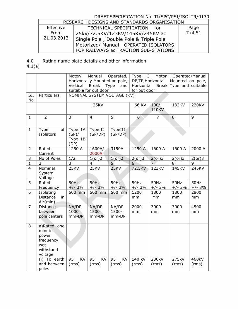
4.0 Rating name plate details and other information 4.1(a)
Motor/ Manual Operated,
Horizontally Mounted on pole,
Vertical Break Type and
suitable for out door
Type 3 Motor Operated/Manual
DP,TP,Horizontal Mounted on pole,
Horizontal Break Type and suitable
for out door
SI.
No
Particulars NOMINAL SYSTEM VOLTAGE (KV)
25KV 66 KV 100/
110KV
132KV 220KV
1 2 3 4 5 6 7 8 9
1 Type of
Isolators
Type 1A
(SP)/
Type 1B
(DP)
Type II
(SP/DP)
TypeIII
(SP/DP)
2 Rated
Current
1250 A
1600A/
2000A
3150A 1250 A 1600 A 1600 A 2000 A
3 No of Poles 1/2 1(or)2 1(or)2 2(or)3 2(or)3 2(or)3 2(or)3
1 2 3 4 5 6 7 8 9
4 Nominal
System
Voltage
25KV 25KV 25KV 72.5KV 123KV 145KV 245KV
5 Rated
Frequency
50Hz
+/- 3%
50Hz
+/- 3%
50Hz
+/- 3%
50Hz
+/- 3%
50Hz
+/- 3%
50Hz
+/- 3%
50Hz
+/- 3%
6 Isolating
Distance in
Air(min)
500 mm 500 mm 500 mm 1200
mm
1800
Mm
1800
mm
2800
mm
7 Distance
between
pole centers
NA/DP
1000
mm-DP
NA/DP
1500
mm-DP
NA/DP
1500-
mm-DP
2000
mm
3000
mm
3000
mm
4500
mm
8 a)Rated one
minute
power
frequency
wet
withstand
voltage
(i) To earth
and between
poles
95 KV
(rms)
95 KV
(rms)
95 KV
(rms)
140 kV
(rms)
230kV
(rms)
275kV
(rms)
460kV
(rms)

DRAFT SPECIFICATION No. TI/SPC/PSI/ISOLTR/0130
RESEARCH DESIGNS AND STANDARDS ORGANISATION
Effective
From 21.03.2013
TECHNICAL SPECIFICATION for
25kV/72.5KV/123KV/145KV/245KV ac Single Pole , Double Pole & Triple Pole
Motorized/ Manual OPERATED ISOLATORS
FOR RAILWAYS ac TRACTION SUB-STATIONS
Page
8 of 51
(ii)Across
isolating
distance
110 KV
(rms)
110 KV
(rms)
110 KV
(rms)
160 kV
(rms)
265kv
(rms)
315 kV
(rms)
530 kV
(rms)
b) Lightning
impulse
(1.2/50
micro-
second) with
stand
voltage
(i) To earth
and between
poles
250 KV
(peak)
250 KV
(peak)
250 KV
(peak)
350kV
(Peak)
550 kV
(Peak)
650kVp 1050
kV
(Peak)
(ii) Across
isolating
distance
290 KV
(Peak)
290 KV
(Peak)
290 KV
(Peak)
375kV
(Peak)
630 kV
(Peak)
750 kV
(Peak)
1200kV
(Peak)
9 Rated short
time with
stand
current. for
Three
second
(Both main
& earthling
switch)
20 KA
(rms)
20 KA
(rms)
50 KA
(rms)
31.5kA
(rms)
40 kA
(rms)
40 kA
(rms)
40 kA
(rms)
10 Rated peak
with stand
current both
for main and
earthling
switch
50 KA 50 KA 125 KA 100 KA 100 KA 100 KA 100 KA
11 Temperature
Rise
Name of parts The temperature of any parts of an
isolator shall not exceed the
maximum temperature rise given
below under the conditions specified
in the test clauses- 10.5
Temperature
in degree 0C
Temperature rise at
an ambient
Temperature not
exceeding 40 0C
a)Copper contacts
i) Bare copper or tinned Al
alloy
ii) Silver faced copper, copper
alloy or alloy
75
105
35
65
DRAFT SPECIFICATION No. TI/SPC/PSI/ISOLTR/0130
RESEARCH DESIGNS AND STANDARDS ORGANISATION
Effective
From 21.03.2013
TECHNICAL SPECIFICATION for
25kV/72.5KV/123KV/145KV/245KV ac Single Pole , Double Pole & Triple Pole
Motorized/ Manual OPERATED ISOLATORS
FOR RAILWAYS ac TRACTION SUB-STATIONS
Page
9 of 51
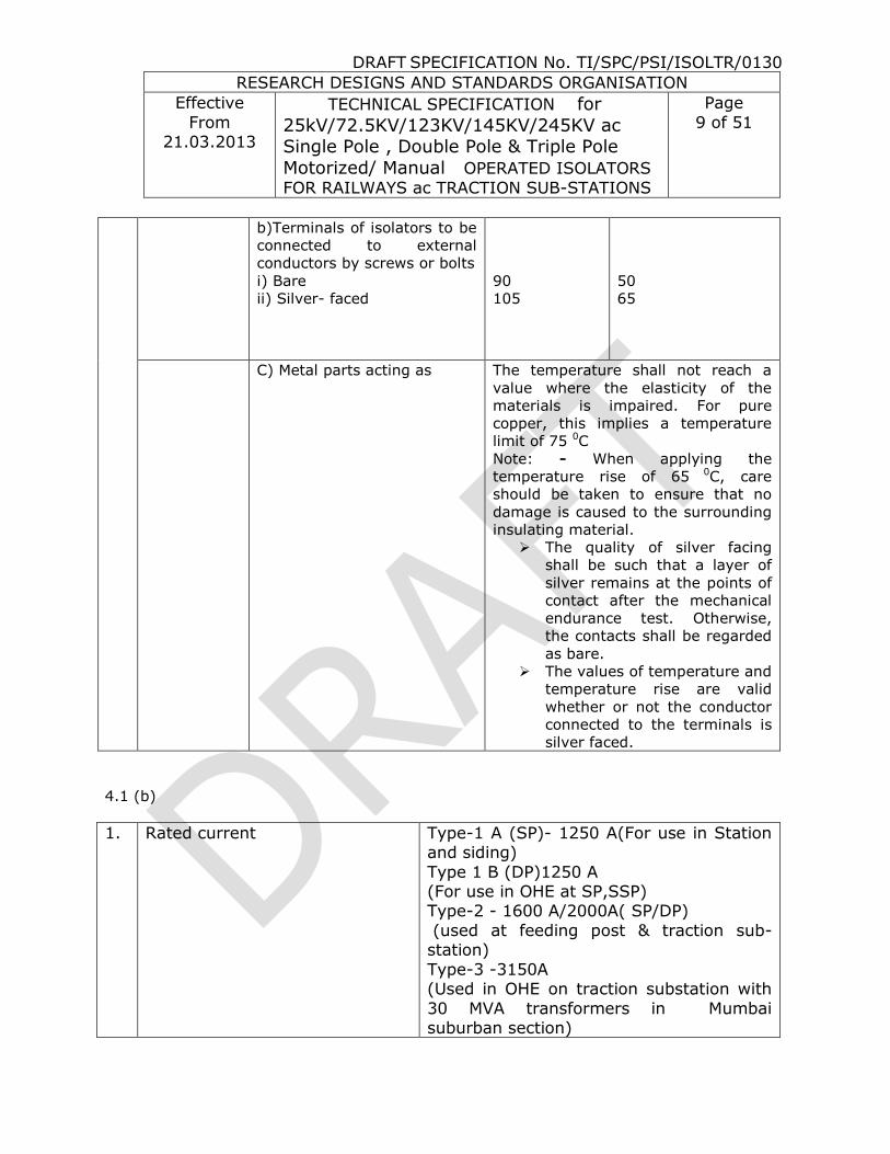
b)Terminals of isolators to be
connected to external
conductors by screws or bolts
i) Bare
ii) Silver- faced
90
105
50
65
C) Metal parts acting as The temperature shall not reach a
value where the elasticity of the
materials is impaired. For pure
copper, this implies a temperature
limit of 75 0C
Note: - When applying the
temperature rise of 65 0C, care
should be taken to ensure that no
damage is caused to the surrounding
insulating material.
The quality of silver facing
shall be such that a layer of
silver remains at the points of
contact after the mechanical
endurance test. Otherwise,
the contacts shall be regarded
as bare.
The values of temperature and
temperature rise are valid
whether or not the conductor
connected to the terminals is
silver faced.
4.1 (b)
1. Rated current Type-1 A (SP)- 1250 A(For use in Station and siding)
Type 1 B (DP)1250 A (For use in OHE at SP,SSP) Type-2 - 1600 A/2000A( SP/DP)
(used at feeding post & traction sub-station)
Type-3 -3150A (Used in OHE on traction substation with
30 MVA transformers in Mumbai suburban section)

DRAFT SPECIFICATION No. TI/SPC/PSI/ISOLTR/0130
RESEARCH DESIGNS AND STANDARDS ORGANISATION
Effective
From 21.03.2013
TECHNICAL SPECIFICATION for
25kV/72.5KV/123KV/145KV/245KV ac Single Pole , Double Pole & Triple Pole
Motorized/ Manual OPERATED ISOLATORS
FOR RAILWAYS ac TRACTION SUB-STATIONS
Page
10 of 51
2. Operating Mechanism (i)Isolator for Station and sidings Type-1 ‘A’- (1250A) = 24 Volt, 40 Ah
battery connected with battery charger for charging shall be provided for 24 V DC
motor drive operating mechanism .Power supply shall be 240 volt AC nominal with variation from 170 to 270 Volts .24V
,40AH Battery & Battery charger with box supplied by manufacturer
(ii) Isolators for SP & SSP Type-1 ‘B’ (1250 A) = Operating
mechanism shall be driven by 110 V DC motor fed by existing 110 Volt, 40 Ah
battery available at SP & SSP ,locations. (iii) Type-2 A (1600) = Operating
mechanism shall be driven by 110 V Dc motor fed by existing 110 Volt battery
available at Sub-stations /posts. (iv) Type- 3 (3150 A) = Operating
mechanism shall be driven by 110 V DC motor fed by existing 110 Volt, battery
available at Sub-stations/ posts.
3. Battery Constructional features / technical
requirements shall be in accordance to RDSO Spec No. RDSO/PE/SPEC/TL/0040-2003(Rev-0) - Low maintenance lead acid
battery.
4. Battery Charger Constructional features/ technical
requirements shall be in accordance to RDSO Spec No. RDSO/PE/SPEC/AC/0008
– August – 2004 (Rev- 1)
Battery and Battery Charger shall be procured from RDSO approved sources only for fitment on the isolator. Type tests once conducted by RDSO, user railways or railway’s authorized inspecting organization will be valid and need
not be repeated during this period.

DRAFT SPECIFICATION No. TI/SPC/PSI/ISOLTR/0130
RESEARCH DESIGNS AND STANDARDS ORGANISATION
Effective
From 21.03.2013
TECHNICAL SPECIFICATION for
25kV/72.5KV/123KV/145KV/245KV ac Single Pole , Double Pole & Triple Pole
Motorized/ Manual OPERATED ISOLATORS
FOR RAILWAYS ac TRACTION SUB-STATIONS
Page
11 of 51
5.0 Design and constructional features
5.1 Operating mechanism The isolator motor shall be suitable for operation with 24 V DC for type I A and
110V DC for type II & III. The voltage at the battery terminals may vary between 110% and 85% of the normal value. The voltage at the isolator motor
terminals is likely to be less than 85% of the normal value of 24 V or 110V due to voltage drop in control cable. The isolator shall be able to operate manually in case of failure of motor circuit. Once the closing /opening operation has been
initiated by driving motor up to the snap actuation point, closing/opening will be completed automatically with snap action even if there is a failure of 24 V or
110 V dc supply at this point. The motor drive unit shall be installed in a weather and corrosion proof,
adequately ventilated cubicle made of sheet steel not less than 2 mm thick with adequate stiffeners to prevent deformation during transit and handling. The
cubicle shall have a sloping roof. To prevent condensation of moisture in the cubicle, metal clad space heater, controlled by an associated thermostat and switch, shall be provided.
The top of the cubicle shall be at a height of about 1.5 m from the rail level.
The cubicle shall be so positioned that the hinge of the operating handle - for manual operation - is at a height of about 1.1 m from the rail level.
The isolator and its control circuit shall be designed for operation from the remote control center (RCC) by the traction power controller (TPC) as well as
from the isolator cubicle. Local/remote spring-loaded switch as well as necessary terminations for tele-signals and telecommands from and to the
isolator- for operation from the RCC- shall therefore be provided in the isolator cubicle. The isolator cubicle shall be provided with motor protection relays.
The operating mechanism shall be such that it is possible to fasten the base to which the operating handle is attached, to either of the two mutually
perpendicular vertical faces of the supporting structure on which the isolator is mounted. The operating handle of the isolator shall be so designed as to work in the vertical plane. The isolator shall close when the handle is moved
upwards. The free end of moving contact shall be fully housed in the fixed contact when the handle is moved fully upward in which position the isolator
can be locked. The design of the single pole isolator shall be such as to permit coupling of isolators for gang operation from a single operating handle. Not more than two single pole isolators are required to be coupled. Suitable “OFF”

DRAFT SPECIFICATION No. TI/SPC/PSI/ISOLTR/0130
RESEARCH DESIGNS AND STANDARDS ORGANISATION
Effective
From 21.03.2013
TECHNICAL SPECIFICATION for
25kV/72.5KV/123KV/145KV/245KV ac Single Pole , Double Pole & Triple Pole
Motorized/ Manual OPERATED ISOLATORS
FOR RAILWAYS ac TRACTION SUB-STATIONS
Page
12 of 51
and “ON” plates shall be provided on the operating handle to indicate when the isolator is open and closed respectively.
All poles of the isolator shall operate simultaneously. Provision shall be made for adjustments, if required, for the proper alignment of the pole after
mounting. All movable joints shall be provided with brass bushes/ bearings, which shall be entirely maintenance free. The blades of the isolator shall be of
electrolytic high conductivity copper tubes of adequate strength and cross section to IS: 191 (Part V) – 1980 to withstand thermal and bending stresses particularly under short circuit fault conditions. Flexible braided copper, where
used, shall have corrosion resistant coating such as tinning or silvering. The connection between the flexible braid and rotating and fixed parts shall be by
means of not less than two bolts to prevent any tendency of rotation. For reasons of safety, the isolator should be so designed that no dangerous leakage current can pass from the terminals of one side to any of the terminals of the
other side.
When installed, the isolator shall be able to bear on terminals the total forces (including wind load and electro dynamic forces on the attached conductors) related to the application and rating without impairing their reliability or current
carrying capacity. The isolator shall be constructed so as to permit it being locked both in the open as well as closed positions. It shall not be possible to
lock the isolator in any intermediate position. The fixed contacts of isolator shall be of extruded, rolled or drawn copper strips. The contacts shall be spring-loaded. Only non-ferrous or stainless steel components shall be used in the
contact assembly. The springs used in the contact assembly of the isolator shall be of phosphor bronze conforming to IS: 7608-1975. To avoid current passing
through the springs, nylon strip of suitable size shall be provided for insulation. The characteristics of the springs shall conform to IS: 7906 (Pt. II)-1976 and
their mechanical properties shall not be affected in any manner on account of rise in temperature during operation. Bolts, nuts locknuts and other fasteners of 12 mm dia and less shall be of stainless steel. Fasteners of higher size may be
made of hot dip galvanized obtained from Central Organization for Railway Electrification, Allahabad. The fasteners shall confirm to RDSO specification No.
ETI/OHE/18. The frame (isolator mounting channel) of each isolator shall be provided with an ear thing terminal for connecting to an ear thing conductor having clamping screws, suitable for earth fault conditions. The diameter of the
clamping screws shall be not less than 12 mm. The connecting point shall be marked with “Earth” ( ) symbol. The Operating pipe shall not have any joint
and shall be supplied with four guides unless otherwise specified in the purchase order. The operating pipe shall be obtained only from approve manufacturers, a list of which may be obtained from CORE/ ALD .All malleable

DRAFT SPECIFICATION No. TI/SPC/PSI/ISOLTR/0130
RESEARCH DESIGNS AND STANDARDS ORGANISATION
Effective
From 21.03.2013
TECHNICAL SPECIFICATION for
25kV/72.5KV/123KV/145KV/245KV ac Single Pole , Double Pole & Triple Pole
Motorized/ Manual OPERATED ISOLATORS
FOR RAILWAYS ac TRACTION SUB-STATIONS
Page
13 of 51
cast iron parts shall be of black heart malleable cast iron grade BM- 340 conforming to IS: 2108-1977.Allferrous parts shall be hot dip galvanized in
accordance with specification No. ETI/OHE/13(4/84).The isolator shall be provided with a terminal pad at each end as shown in Appendix C attached. The terminal pad shall have few holes as indicated for being connected to a terminal
connector.
The general arrangement of the isolator shall be as shown in Appendix C. The essential dimensions are also indicated in the Appendix C.
5.2 Steel structure
The support and framework shall be designed for a wind pressure of 200 kgf/m2 acting on 150 %of the projected area in addition to all other loads. During the opening and operations of the isolator there shall be no shock. There
shall also not be a backlash tending to open the isolator after closing, due to the jerk, if any. The mounting arrangement and the operating mechanism shall
be such that with the isolators mounted in the working position, the hinge pin of the operating handle is at a height of 1.1m from ground level. The height of base of the rigid frame would vary, depending on the type of mast/ or structure
on which the isolator is mounted. The heights for typical masts/ structures are given below:
Location Height of isolator mounting channel from ground level in mm
SP DP
RSJ/BFB mast 8310 8160
RSJ with super mast 9425 9275
R Portal 9535 9385
N Portal 9485 9335
O Portal 9585 9435
Two track cantilever 9560 9410
SS,SSP,SP,FP 3262 ------
5425 5525
(When bus bar height is 5968mm)
The isolator shall be supplied with operating pipe in exact length for the particular mast/ structure, the length being obtained from the purchaser for
each type of mast/ structure.

DRAFT SPECIFICATION No. TI/SPC/PSI/ISOLTR/0130
RESEARCH DESIGNS AND STANDARDS ORGANISATION
Effective
From 21.03.2013
TECHNICAL SPECIFICATION for
25kV/72.5KV/123KV/145KV/245KV ac Single Pole , Double Pole & Triple Pole
Motorized/ Manual OPERATED ISOLATORS
FOR RAILWAYS ac TRACTION SUB-STATIONS
Page
14 of 51
5.3 Insulators
The support and operating rod insulators shall be of solid core/composite type in accordance with the latest specification of RDSO viz No. ETI/OHE/15 (9.91) with A&C Slip No.1 to 6 or composite type as per RDSO
Spec.No.TI/SPC/OHE/INSCOM/0991and shall be procured, if included in the order, only from the approved manufacturers as per drawings approved by
RDSO.
5.4 Isolator
5.1.1 The isolator shall be robust in construction and so engineered as to ensure
operation at all times.
5.1.2 The moving blades shall rotate through 900 from their fully closed position to
fully open position, so that the break is distinct and clearly visible from ground level
5.1.3 The isolator shall be designed to minimize the shock during opening and closing
operations, and shall not have a backlash tending to open the isolator after
closing due to jerk. The isolator shall be so designed that it can come off its open/close position by vibrations, shocks or any other means except when
specifically operated with the help of its operating handle. 5.1.4 The rotating blade (s) on the moving poles shall operate simultaneously. An
arrangement for necessary adjustment to achieve this feature shall be provided.
5.1.5 Main contacts
i The isolator shall have heavy-duty self-aligning and high-pressure contacts of modern design.
ii The contacts of the isolator shall be in the form of reverse loop so that
during passage of short circuit current they exert additional pressure on the moving contacts.
iii The blades of the isolator shall be of rotating type at its longitudinal axis by the turn and twist mechanism provided in the moving contact assembly.
iv The moving and fixed contact assemblies shall be so designed as to ensure
a) Electro dynamic forces with stand ability during shat circuit without risk of
dislodging of moving contact firm the fixed contact;
DRAFT SPECIFICATION No. TI/SPC/PSI/ISOLTR/0130
RESEARCH DESIGNS AND STANDARDS ORGANISATION
Effective
From 21.03.2013
TECHNICAL SPECIFICATION for
25kV/72.5KV/123KV/145KV/245KV ac Single Pole , Double Pole & Triple Pole
Motorized/ Manual OPERATED ISOLATORS
FOR RAILWAYS ac TRACTION SUB-STATIONS
Page
15 of 51
b) thermal with stand ability during short circuits; c) Constant contact pressure even when the live parts of the insulator stacks
are subjected to tensile stress due to liner expansion of connected bus bar conductor, either because of temperature variation or strong wides.
d) Wiping and self-cleaning action during closing and opening, and
e) Self- aligning ensuring smooth closing of the isolator.
5.1.6 Earthling switch 1) The ear thing switch shall be manually/Motor operated. 2) The moving contact shall be made of electrolytic high-conductivity
copper of adequacy strength to with stand all thermal and bending stresses at the time of short circuits.
3) The fixed contacts shall be identical to the main isolator fixed contacts expect for silver plating.
4) The ear thing of the moving contact shall be affected by flexible copper
braids of adequate cross-section safely carry the short circuit current specified clause 4.1(a) above.
5) The earthling switch for all poles of the isolator shall be mounted on the same shaft and operated by a single and common operating handle, which shall be distinct and separate from that used for operating the
isolator. 6) The moving contacts of the ear thing switch shall close home
simultaneously in the fixed contacts. 7) Suitable counterweights shall be provided in the operating mechanism of
the earthling switch, so that while opening the moving contacts it does
not come to rest with a jerk.
5.1.7 Terminal pad and terminal connectors
5.1.7.1 The isolator shall be provided with hard–drawn, extruded or rolled electrolytic copper terminal pad on either end to be connected to the terminal connectors.
5.1.7.2. The terminal connectors shall be of bimetallic type to prevent electrolytic
corrosion and shall conform to RDSO’s standard drawings, which are enclosed with this specification.
5.1.8 Material for various components
5.1.8.1 The blades of the isolator shall be of electrolytic high conductivity copper with the ends silver-plated (minimum thickness 10 microns) and of
DRAFT SPECIFICATION No. TI/SPC/PSI/ISOLTR/0130
RESEARCH DESIGNS AND STANDARDS ORGANISATION
Effective
From 21.03.2013
TECHNICAL SPECIFICATION for
25kV/72.5KV/123KV/145KV/245KV ac Single Pole , Double Pole & Triple Pole
Motorized/ Manual OPERATED ISOLATORS
FOR RAILWAYS ac TRACTION SUB-STATIONS
Page
16 of 51
adequate strength to withstand all thermal and bending stresses, particularly, at the time of passage of short circuit currents.
5.1.8.2 The fixed contacts of the isolator shall be made out of copper, extruded,
rolled or drawn. They shall be silver- plated (minimum thickness 10
microns)
5.1.8.3 Bolts, nuts and other fasteners of 12 mm dia or less shall be of stainless steel. Higher sizes of fasteners may be of hot-dip galvanized steel to RDSO’s specification No. ETI/OHE/13(4/84).Spring washers wherever
used shall be procured from RDSO’s approved manufactures .
5.1.8.4 All ferrous parts used in the manufacture of the isolator shall be hot-dip galvanized to RDSO’s specification No.ETI/OHE/13(4/84).
5.1.9 Earthling
5.1.9.1 The frame of the isolator shall be provided with two ear thing studs of size of size M 16, complete with flat washer, nut and locknut, for connection to the earth mat with the help of MS flat. The ear thing stud
shall be marked with “Earth” symbol.
5.1.9.2 Two number each of earthling terminals shall be provided for earthling the operating mechanism boxes of the Isolator and the earthling switch.
5.2 Operating mechanism
5.2.1 Isolator
5.2.1.1 The isolator shall be suitable for being conveniently operated manually from the ground level without any strain. The design shall permit the length of operating rod to be s adjusted that, with the isolator mounted in working
position, the rotating shaft of the operating mechanism on which the operating handle would be connected I at a height of 1.1 m from the
ground level. 5.2.1.2 Operating mechanism shall be provided with a sealed type reduction gear
unit so as to facilitate easy operation of the isolator. Means for greasing the gear assembly shall be available for periodical maintenance of the unit.
5.2.1.3 Suitable arrangement shall be made on the inner side of the operating
mechanism door for keeping the operating handle when not in use.

DRAFT SPECIFICATION No. TI/SPC/PSI/ISOLTR/0130
RESEARCH DESIGNS AND STANDARDS ORGANISATION
Effective
From 21.03.2013
TECHNICAL SPECIFICATION for
25kV/72.5KV/123KV/145KV/245KV ac Single Pole , Double Pole & Triple Pole
Motorized/ Manual OPERATED ISOLATORS
FOR RAILWAYS ac TRACTION SUB-STATIONS
Page
17 of 51
5.2.1.4 A mechanical ON/OFF indicator shall be provided on the operating
mechanism box for indicating the isolator position. This should be visible from a distance.
5.2.1.5 The operating mechanism shall be designed in such a way so that, which minimum modifications, the isolator can be converted from manual to
motor- operated. 5.2.1 6. The operating mechanism and accessories shall be enclosed in a weather ,
dust and vermin-proof cabinet of sheet steel construction having a minimum thickness of 2mm.The operating mechanism box shall be hot-dip
galvanized to RDSO’s Specification No.ETI/OHE/13(4/84).
5.2.2 Earthling switch
5.2.2.1 Earthling switch shall be suitable for being conveniently operated manually
from ground level without any strain. The design shall permit the length of operating rod to be so adjusted that, with the ear thing switch mounted in working condition, the hinge pin of the operating handle is at a height of
1.1m from the ground level.
5.2.2.2 The operating handle shall rest in the vertical position, both when the ear thing switch is in Open/Close position.
5.2.2 3 A mechanical ON/OFF indicator for ear thing switch position, when the operation of the ear thing switch is complete, shall be provided on the ear
thing switch assembly. This indication should be visible from a distance.
5.2.2.4 A weather, dust and vermin-proof cabinet of sheet steel construction having a minimum thickness of 2 mm shall be provided for housing the interlock and integral lock. The cabinet shall be hot-dip galvanized to
RDSO Specification No.ETI/OHE/13 (4/84).

DRAFT SPECIFICATION No. TI/SPC/PSI/ISOLTR/0130
RESEARCH DESIGNS AND STANDARDS ORGANISATION
Effective
From 21.03.2013
TECHNICAL SPECIFICATION for
25kV/72.5KV/123KV/145KV/245KV ac Single Pole , Double Pole & Triple Pole
Motorized/ Manual OPERATED ISOLATORS
FOR RAILWAYS ac TRACTION SUB-STATIONS
Page
18 of 51
5.3 Cylindrical post insulators (Support insulator)
5.3.1 The cylindrical post insulators shall conform entirely to RDSO Specification
No.ETI/OHE/64(10/88).Including the latest amendment .However, the
salient characteristics of the insulators are given below for ready reference:
S.
No.
Particulars Rated System Voltage
72.5kV 123kV 145kV 245kV
(1) (2) (3) (4) (5) (6)
i. Nominal System Voltage 66kV 100/110kV 132kV 220kV
ii. Overall height 770
+/-1mm
1200
1+/-1mm
1500
+/-2.5mm
2300
+/-3.5mm
iii. Maximum diameter of
Insulating part
195mm 210mm 270mm 300mm
iv. Top metal fitting pitch
circle diameter
127mm 127mm 127mm 127mm
v. Bottom metal fitting
pitch circle diameter
127mm 127mm 127mm 200mm
vi. Minimum creep age
distance
1810mm 3075mm 3625mm 6125mm
vii. Visible discharge test
voltage.
53kV 88kV 106kV 176kV
viii. Wet 1 minute power
frequency withstand
voltage
160kV
(rms)
230kV
(rms)
275kV
(rms)
460kV
(rms)
ix. Impulse voltage with
stand value
350kVp 550kVp 650kVp 1050kVp
x. Minimum failing load in
bending
4kN 4kN 4kN 4kN
xi. Minimum failing load in
tension
35kN 50kN 60kN 160kN
xii. Minimum failing load in
torsion
2kNm 3kNm 3kNm 3kNm
xiii. Minimum failing load in
compression.
70kN 100kN 120kN 160kN
5.3.2 The insulator shall be produced only from RDSO approved manufacturers.
5.4 Locking and inter locking
5.4.1 Isolator
5.4.1.1 The operating mechanism box shall have provision for a pad lock for

DRAFT SPECIFICATION No. TI/SPC/PSI/ISOLTR/0130
RESEARCH DESIGNS AND STANDARDS ORGANISATION
Effective
From 21.03.2013
TECHNICAL SPECIFICATION for
25kV/72.5KV/123KV/145KV/245KV ac Single Pole , Double Pole & Triple Pole
Motorized/ Manual OPERATED ISOLATORS
FOR RAILWAYS ac TRACTION SUB-STATIONS
Page
19 of 51
Locking its door.
5.4.1 2 The isolator shall have provision for locking its main rotating shaft with the help of pad lock , both in ‘Open’ as well as in ‘Closed’ position shall not be possible.
5.4.1 3 Besides the above, the isolators shall have two locking mechanisms, for the
purpose of interlocking with the associated Circuit Breaker(s). The Inter Locking shall be as per Scheme –I and II detailed in Drg. No. ETI/PSI/5212 attached with this Specification. The locks for this purpose shall not be in
the scope of supply by the successful tenderer. However mounting arrangement for these locks shall be provided by the manufacturer in such
a way that it is possible to insert the key(s) from outside for operation of locks(s). The successful tenderer shall coordinate with manufacturer of circuit breaker and the purchaser for this purpose.
5.4.2 Ear thing switch:
5.4.2.1 The operating mechanism box shall have provision for a pad lock for locking
its lid.
5.4.2.2 A mechanical inter lock shall be provided in the operating mechanism of isolator and ear thing switch, so that operation of ear thing switch is
possible only when the isolator is locked in open position .This inter lock shall also prevent closing of isolator unless ear thing is locked in open position.
5.4.2.3 An integral lock shall be fitted in the operating mechanism box of the ear
thing switch for locking the operating mechanism both in ‘Open’ as well as in ‘Closed’ positions.
5.4.2.4 The design of the ear thing switch shall be such as to permit use of a pad
lock for locking the operating handle of the ear thing switch in both ‘Open’
as well as in ‘Closed’ positions.
5.4.3 The locking mechanism mentioned in Clause 5.4.2.3 shall be housed within the operating mechanism box. It shall however, be possible to insert the key from outside for operation of lock.
5.5 Bearings
5.5.1 The design and construction of various bearing shall embody all the features
required to with stand the climatic conditions specified to ensure reliable

DRAFT SPECIFICATION No. TI/SPC/PSI/ISOLTR/0130
RESEARCH DESIGNS AND STANDARDS ORGANISATION
Effective
From 21.03.2013
TECHNICAL SPECIFICATION for
25kV/72.5KV/123KV/145KV/245KV ac Single Pole , Double Pole & Triple Pole
Motorized/ Manual OPERATED ISOLATORS
FOR RAILWAYS ac TRACTION SUB-STATIONS
Page
20 of 51
operation even after long periods of inaction .The bearings used shall be of maintenance free construction for entire life of isolator.
5.6 Support Structure
5.6.1 The support structure shall not form part of the tender and shall be arranged by the purchaser. Details of the drilling schedule of the holes for the purpose
of mounting the isolators on the support structure shall be ascertained by the successful tender from the purchaser before manufacturing the proto type.
5.6.2 The isolator and the ear thing switch (Wherever provided) shall be mounted rigidly in upright position on the support structure. The height of the support
structure from the ground level, for all types of isolators shall be 3000mm. 5.7 Tandem pipes
5.7.1 For smooth operation of the isolator, and to avoid buckling and bending of
the tandem pipes of the isolators, while opening or closing, an arrangement as indicated in sketch No. ETI/PSI/SK/322 enclosed with specification, shall be provided. An adjustable turn buckle /nut shall be provided (as shown in
the sketch), for adjusting the length of the tandem pipe (s) at site.
5.8 Nameplate 5.8.1 The isolator and the ear thing switch shall be provided with a separate
nameplate each, which shall be water –proof and corrosion-proof, and mounted such that it is clearly visible by a person standing on the ground.
Following information shall be indicated indelibly on these nameplates:
5.8.1 Isolator
Name of manufacturer
Type designation Serial Number
Rated voltage Basic Insulation Level Rated shot- time with stand current for one second.
Weight.
5.8.2 Ear thing switch
Name of manufacturer

DRAFT SPECIFICATION No. TI/SPC/PSI/ISOLTR/0130
RESEARCH DESIGNS AND STANDARDS ORGANISATION
Effective
From 21.03.2013
TECHNICAL SPECIFICATION for
25kV/72.5KV/123KV/145KV/245KV ac Single Pole , Double Pole & Triple Pole
Motorized/ Manual OPERATED ISOLATORS
FOR RAILWAYS ac TRACTION SUB-STATIONS
Page
21 of 51
Type of designation Serial Number
Rated voltage Rated short- time withstand current for one second.
The terminal shall be complete with its steel mounting frame
6.0 LOCKING:
A bolt type integral lock and /or interlock, as specified by the
purchaser, of approved type shall be fitted on the isolator to enable the operating handle of the isolator to be locked effectively in the open as well as
in the close position. It shall not be possible to withdraw the key from the integral lock except when the isolator is locked either in the open or in the closed position.
The operating mechanism shall be so designed as to permit padlocking,
in addition to the integral lock and or interlock, for locking the operating handle of the isolator both in the open as well as in the closed positions.
In addition to locking arrangement described in clause 8.1, the design of operating mechanism shall permit its operation in a predetermined
sequence related to the operation of other switchgear with the help of suitable inter locks.
The internal mechanism of integral lock and inter lock shall be of stainless steel or non-ferrous material. It shall be of robust construction. The
outer housing of the interlock and integral lock shall be chrome plated steel and the construction shall be such that it is not prone to theft. The integral
lock and interlock shall be obtained only from the approved manufacturers. Electrical/mechanical interlocking shall be provided for manual/motorized operation.
Each lock shall be supplied with two keys. Key/lock number shall be inscribed on the keys /locks.
7.0 EARTH CONTACT ASSEMBLY:
The design of the isolator shall be such that it is possible to incorporate an additional pair of contacts so as to effectively earth the fixed contact of the
isolator in open position even at a later date. The design of the isolator frame shall permit the provision of the earth contact assembly without calling for modification to the frame itself. Two holes of 15.5 + 0.5 mm dia shall be

DRAFT SPECIFICATION No. TI/SPC/PSI/ISOLTR/0130
RESEARCH DESIGNS AND STANDARDS ORGANISATION
Effective
From 21.03.2013
TECHNICAL SPECIFICATION for
25kV/72.5KV/123KV/145KV/245KV ac Single Pole , Double Pole & Triple Pole
Motorized/ Manual OPERATED ISOLATORS
FOR RAILWAYS ac TRACTION SUB-STATIONS
Page
22 of 51
provided on the mounting channel for connecting assembly shall be rated for the short time current specified in clause 4.0 (9) & (10).
8.0 ARCING HORN:
The single pole isolator shall be provided with arcing horns which shall be of
bright steel to Gr. 20-c-8 of IS: 1570 (Pt. II )- 1979. The arcing horns shall make contact before the main contacts close and break contact after the main
contacts break. 9.0 Motor:
Permanent Magnet DC motor ½ HP, 373 watts and above shall be suitable for
operation on 110V DC/24V DC Power from a battery. The voltage at the motor terminals likely to vary between 110% to 85% of the normal value.
9.1 GEAR:
The dis-connector/ isolator may be required to operate occasionally, with considerably long idle intervals. Special care shall be taken for selection of material for gear and lubrication of gears to meet this requirement. The gear
shall be made out of aluminum bronze or any other better material lubricated for life with graphite or better quality non-drawing and non-hardening type
grease .Whenever necessary automatic relieving mechanism shall be provided suitable relay, Device shall be provided to prevent over loading of the motor. Single phase preventer (for 3 phase meter) shall be provided to operate on
open circuiting of any phase and shall trip off the motor. Complete details of the devices shall be furnished in the offer.
9.2 Space heaters:
Space heaters suitable for 1 phase 240V Ac supply shall be provided for each motor operated operating mechanism to prevent condensation and shall be
operated by MCB.
9.3 Terminal blocks and wirings: Each operating mechanism shall be provided with 1100V grade stud type
terminal block. All auxiliary switches, interlocks and other terminals shall be wired up to terminal block. The terminal block shall have at least 20% extra
terminals. All wiring shall be carried out with 1.1 KV grade insulated 2.5 sq. mm copper wires.

DRAFT SPECIFICATION No. TI/SPC/PSI/ISOLTR/0130
RESEARCH DESIGNS AND STANDARDS ORGANISATION
Effective
From 21.03.2013
TECHNICAL SPECIFICATION for
25kV/72.5KV/123KV/145KV/245KV ac Single Pole , Double Pole & Triple Pole
Motorized/ Manual OPERATED ISOLATORS
FOR RAILWAYS ac TRACTION SUB-STATIONS
Page
23 of 51
10.0 TESTS:
10.1 Type tests Only after all the designs and drawings have been approved and clearance
given by RDSO/Chief Electrical Engineer to this effect, the manufacturer shall take up the manufacture of the prototype. It is to be clearly understood that
any changes to be done in the prototype as required by RDSO/Chief Electrical Engineer shall be done expeditiously.
Before giving the call to RDSO/Chief Electrical Engineer for inspection and testing of the prototype, the manufacturer shall submit a detailed test
schedule prototype, the manufacturer shall submit a detailed test schedule consisting of schematic circuit diagram for each of the test and the nature of the test, venue and duration of each test and the total number of the days
required to complete the test at one stretch. Once the schedule is approved, the test shall invariably be done accordingly. However, during the process of
type testing or even later, RDSO/ Chief Electrical Engineer’s representative reserves the right to conduct any additional test(s) beside those specified herein, on any equipment/ sub- system or system so as to test the system to
his satisfaction or for gaining additional information and knowledge. In case any dispute or disagreement arises between the manufacturer and RDSO/ the
Chief Electrical Engineer during the process of testing as regards the type tests and / or the interpretation and acceptability of the type test results, it shall be brought to the notice of the Director General (Traction Installations),
RDSO/Chief Electrical Engineer as the case may be, whose decision shall be final and binding.
The following tests shall be carried out on the prototype unit of the
isolator and earthing switch at the works of the manufacturer/ sub- contractor or at a reputed testing laboratory, in the presence of RDSO/Chief Electrical Engineer’s representative(s) in accordance with the relevant governing
specification and/or as modified or amplified hereunder against each test:
i Visual examination of isolator and its parts. ii Dimensional verification of parts iii Assembly and interchangeability
iv Measurement of resistance of main circuit and /earth circuit (Before and After Mechanical Endurance test)
v Temperature rise test (before and after mechanical endurance test) vi Mechanical endurance test vii Short time rated current test.

DRAFT SPECIFICATION No. TI/SPC/PSI/ISOLTR/0130
RESEARCH DESIGNS AND STANDARDS ORGANISATION
Effective
From 21.03.2013
TECHNICAL SPECIFICATION for
25kV/72.5KV/123KV/145KV/245KV ac Single Pole , Double Pole & Triple Pole
Motorized/ Manual OPERATED ISOLATORS
FOR RAILWAYS ac TRACTION SUB-STATIONS
Page
24 of 51
viii One minute wet power frequency test across the isolating distance and to Earth.
ix Impulse voltage withstand test across isolating distance and to earth x Galvanization test xi Chemical analysis of materials – copper contacts, springs, fasteners
and Bushes xii Physical tests on springs and fasteners and copper strips.
xiii Closing /Opening operations will be carried out with stored energy of the battery in fully charged condition to verify suitability of the battery provided by manufactures.
10.2 Acceptance tests
10.2.1 For the purpose of acceptance isolators shall be offered for inspection in lots
containing components for not more than 50 assemblies of same type of
isolators. The isolators offered for inspection shall first be routine tested by the manufacturer and defective components removed.
10.2.2 The visual examination and measurement of resistance shall be done on all
the isolators offered for inspection .The defective ones shall be either
attended to or removed before tests are conducted.
10.2.3 The following shall comprise the acceptance test: i) Visual examination (on every item of the lot)
ii) Dimensional verification of parts (on 10% sample of the lot, minimum
one Number) iii) Assembly and interchangeability (of minimum 3)
iv) Galvanization test (one sample of each item) v) Measurement of resistance (all samples)
vi) 10 closing /Opening operations will be carried out with stored energy of the battery in fully charged condition to verify suitability of the battery provided by manufactures.
10.2.4 The inspector may, at his discretion, conduct any or all of the tests (clause
10.1), (clause 10.2) and (clause 10.3) for a particular lot. The manufacturer shall arrange for the test.
10.2.5 Acceptance Criteria
10.2.5.1 If during dimensional verification of parts assembly and interchangeability, any component fails to meet the requirement of this specification, twice the number of the same shall be taken and the tests repeated. If the
DRAFT SPECIFICATION No. TI/SPC/PSI/ISOLTR/0130
RESEARCH DESIGNS AND STANDARDS ORGANISATION
Effective
From 21.03.2013
TECHNICAL SPECIFICATION for
25kV/72.5KV/123KV/145KV/245KV ac Single Pole , Double Pole & Triple Pole
Motorized/ Manual OPERATED ISOLATORS
FOR RAILWAYS ac TRACTION SUB-STATIONS
Page
25 of 51
component(s) fail to meet the requirement again, the lot shall be rejected. The manufacturer may sort out the defective pieces and offer
the lot once again, should there be any failure in the lot offered once again, the lot shall be rejected totally.
10.2.5.2 If the sample fails to meet the requirements of Cl 9.0 twice the number of samples for same components/ assembly shall be drawn and subjected
to the same test. Should the sample fail in the re- test, the lot of particular component will be rejected. The manufacturer may reassemble the isolators using the new components and offer once again for
inspection.
10.3 Routine tests. The manufacturer shall carry out the following as routine tests:
a. Visual examination.
b. Dimensional verification of parts. c. Assembly and interchangeability. d. Power frequency voltage dry withstand tests (on the Isolator
only) for72.5kV & above. e. Measurement of contact resistance for 72.5kV & above.
The manufacturer shall offer record of the routine tests and acceptance tests
carried out by him to ensure quality of raw materials, to the inspector. Unless
these are satisfactory, no acceptance test shall be carried out, Mention of routine tests and acceptance tests carried out by the manufacturer shall be
made in the test report and salient extracts reproduced.
11.0 TEST METHODS 11.1 Visual examination
All components shall be visually examined to check that they are properly
manufactured, do not have sharp edges and corners, the tubes are not crooked or bent and galvanization of ferrous components is free from visible defects mentioned in Appendix ‘A’ of RDSO specification No. ETI/OHE/13
latest version. The finish of stainless steel fasteners and pins shall be smooth and bright.

DRAFT SPECIFICATION No. TI/SPC/PSI/ISOLTR/0130
RESEARCH DESIGNS AND STANDARDS ORGANISATION
Effective
From 21.03.2013
TECHNICAL SPECIFICATION for
25kV/72.5KV/123KV/145KV/245KV ac Single Pole , Double Pole & Triple Pole
Motorized/ Manual OPERATED ISOLATORS
FOR RAILWAYS ac TRACTION SUB-STATIONS
Page
26 of 51
11.2 Dimension verification
The components of the isolators, particularly –moving contact blade, the spring of the fixed contact, the housing for fixing contact jaws on the post insulators, the fixed and moving contact jaws, the operating shaft for the
operating pipe and the contacts shall be checked with respect to the approved drawings. The components shall be in accordance with the approved
drawings. 11.3 Assembly and interchangeability
11.3.1 The isolator shall be assembled, using the components picked up at random
from different lots .No adjustments shall be required in any assembly the isolator shall function smoothly without any adjustments.
11.3.2 The components such as the housing for the fixed and moving contacts, the housing for the earth contact assembly shall then be interchanged to ensure
to ensure that the components are fully interchangeable. Fixing of different components shall be without any difficulty and any special adjustment.
11.3.3 The dimensions of the isolator assembly, particularly the following critical ones shall be verified.
i. Minimum clearance between moving blade and the jaw of the fixed
Contact at free end when the isolator is open.
ii. The clearance between the earth end of the operating rod insulator with Both the live terminals in closed as well as open positions.
iii. The travel of the moving blade with full travel of operating pipe. iv. The distance between the centers of all the holes of the isolator
Assembly for fixing it on the masts. v. When the isolator is in fully closed position, the moving contact shall
go home fully into the fixed contact and no portion shall Remain
Projecting beyond the fixed contact on the upper side. The main contact shall not exert undue pressure on the stopper.
11.4 Measurement of the resistance of the main circuit/earth circuit.
11.4.1 This measurement is made for comparison between the isolator type tested for temperature rise and all other isolator of the same type subjected to
acceptance tests.

DRAFT SPECIFICATION No. TI/SPC/PSI/ISOLTR/0130
RESEARCH DESIGNS AND STANDARDS ORGANISATION
Effective
From 21.03.2013
TECHNICAL SPECIFICATION for
25kV/72.5KV/123KV/145KV/245KV ac Single Pole , Double Pole & Triple Pole
Motorized/ Manual OPERATED ISOLATORS
FOR RAILWAYS ac TRACTION SUB-STATIONS
Page
27 of 51
11.4.2 The direct current of any convenient value between 100 A and the rated normal current shall be passed through the main circuit /earthing contact
circuit as the case may be and the voltage drop between the two terminals of each pole of the isolator shall be measured to obtain the resistance at the ambient temperature. All values measured/obtained shall be recorded.
11.4.3 The measurement of resistance shall be made before the temperature rise
test. 11.4.4 The test shall also be conducted during acceptance test. The maximum
value of resistance shall not exceed 1.5 times the resistance obtained during type tests or RxT/t,
Whichever is lower, where – R = Resistance obtained during type test.
T = Permissible temperature rise (35 deg. C) t = Temperature rise obtained during type tests at the hottest spot.
11.4.5 For the purpose of the acceptance test, the measurement of resistance may
be made by using micro-ohm meter calibrated to the satisfaction of the
inspector.
11.5 Temperature rise test 11.5.1 The test for temperature rise of main circuit shall be made on a new isolator
with clean contact pieces. The isolator shall be mounted approximately as under usual service conditions, including all normal covers of any part of the
isolator, and shall be protected against undue heating or cooling.
11.5.2 Temporary connections to the main circuit shall be such that no appreciable amount of heat is conducted away from or conveyed to the isolator during the test. In case of doubt, the temperature rise of the terminals of the main
circuit and at temporary connections at a distance of 1 m from the terminals shall be measured. The difference of temperature shall not exceed 50 C.
11.5.3 The test shall be made with the rated normal current of the isolator (i.e.
1250A for isolators for SSP and SP, 1600 A for isolators to be used at FP and
TSS and 3150 A for type III isolators) and at rated frequency (50Hz +/-3%).
11.5.4 The duration of the test shall be made over a period of time sufficient for the temperature to reach a steady state i.e. when the variation of temperature does not exceed 1 deg. C per hour over three hours.

DRAFT SPECIFICATION No. TI/SPC/PSI/ISOLTR/0130
RESEARCH DESIGNS AND STANDARDS ORGANISATION
Effective
From 21.03.2013
TECHNICAL SPECIFICATION for
25kV/72.5KV/123KV/145KV/245KV ac Single Pole , Double Pole & Triple Pole
Motorized/ Manual OPERATED ISOLATORS
FOR RAILWAYS ac TRACTION SUB-STATIONS
Page
28 of 51
11.5.5 The temperature of the different parts shall be measured with
thermometers, thermocouples or other suitable means, placed at the hottest accessible spot. The following precautions shall be taken when measuring with thermocouples or thermometers:
i. Thermocouples or the bulbs of thermometers shall be protected
against being cooled from outside during the test. The protected surface area shall, however, be negligible when compared with the cooling surface area of the part under test.
ii. Good heat conductivity between the bulb of the thermometers or the
thermocouples and the surface of the part under test shall be insured.
iii. Alcohol thermometers shall be used as they are accurate for such purposes.
11.5.6 The time for the whole test may be shortened by preheating the circuit with
a higher value of current.
11.5.7 In case the temperature rise at any part of the isolator exceeds the values
specified in Clause 4.0(11), the isolator shall deemed to have failed in the test.
11.6 Mechanical Endurance Test
11.6.1 The mechanical endurance test shall be conducted in accordance with IS: 9921 (Pt. IV) but the number of operating cycles shall be 5000 instead of
1000 as specified their n. The condition of all parts shall be satisfactory after the test. On successful completion, the test shall be continued up to 10000 cycles to determine the weak spots.
11.6.2 For this test, the isolator shall be complete with operating and locking
mechanism etc. 11.7 Short time withstand current test
11.7.1 The test shall be conducted at the current value specified in Clause 4.0 (9)
for 3 s.The ac component of the test current shall be equal to the ac component of the rated short time withstand current of the isolator or

DRAFT SPECIFICATION No. TI/SPC/PSI/ISOLTR/0130
RESEARCH DESIGNS AND STANDARDS ORGANISATION
Effective
From 21.03.2013
TECHNICAL SPECIFICATION for
25kV/72.5KV/123KV/145KV/245KV ac Single Pole , Double Pole & Triple Pole
Motorized/ Manual OPERATED ISOLATORS
FOR RAILWAYS ac TRACTION SUB-STATIONS
Page
29 of 51
Earthing switch. The peak current shall not be less than the rated peak withstand current but shall not exceed it by more than 5% without the
consent of the manufacturer. 11.7.2 The value of the test current and its duration shall be such that I1
2 .t1=I2.t
Where – I1= r.m.s. component of test current measured in accordance with Appendix
to IS: 9921(Pt.IV) in A. I = r.m.s. component of specified short –time current in A (20,000 A). t = Specified short time current duration in seconds (3 s)
t1 = Duration of current in s. Note: This test shall be conducted at Central Power Research Institute,
Bangalore/Bhopal only, unless otherwise approved by RDSO. 11.7.3 During the test to prove its capability of carrying the rated peak withstand
current and the rated short time withstand current, the isolator or earthing switch shall not show undue stress. After the test, the isolator or earthing
switch shall not show any material deterioration and shall be capable of operating normally.
11.7.4 Visual inspection and no-load operation of the tested isolator or ear thing switch are usually sufficient to check these requirements.
11.7.5 The test may be considered completed successfully if the isolator can be
operated manually after tests. There should be no damage, which may
affect its mechanical and electrical performance.
11.7.6 If after the test, there is any doubt about its current carrying capability; temperature rise test shall be made before the isolator is reconditioned. The
value of temperature rise shall not exceed the figure given in Clause 4.0(9). 11.8 Wet power frequency voltage withstand test
11.8.1 The isolator and earthing switch shall be subjected to wet power frequency
voltage withstand test in accordance with IS: 2071 (Pt. I & II).The test voltage shall be raised for each test condition to the rated withstand voltage, duly corrected for the ambient atmospheric conditions, specified in
Cl. 4.0(11) and shall be maintained for 1 min. No disruptive discharge shall take place during the 1 min period.
11.8.2 The wet power frequency voltage withstand test shall be conducted in
accordance with IS: 2071 (Pt. I). However, if the water of prescribed

DRAFT SPECIFICATION No. TI/SPC/PSI/ISOLTR/0130
RESEARCH DESIGNS AND STANDARDS ORGANISATION
Effective
From 21.03.2013
TECHNICAL SPECIFICATION for
25kV/72.5KV/123KV/145KV/245KV ac Single Pole , Double Pole & Triple Pole
Motorized/ Manual OPERATED ISOLATORS
FOR RAILWAYS ac TRACTION SUB-STATIONS
Page
30 of 51
resistivity cannot be obtained, water of lower resistivity may be used, provided that the isolator passes the test. The actual value of resistivity of
the water and the rate of precipitation (both horizontal and vertical components) shall be stated in the test report.
11.8.3 The test shall be conducted in following conditions:
11.8.3.1 Between isolator and earth: With the isolator in the closed position, the test voltage shall be applied to one of the 25kV terminals, the support frame – work and the other pole connected together and earthed.
11.8.3.2 Across isolating distance: With the isolator in the open condition, the test
voltage duly corrected for ambient conditions, shall be applied at the moving blade(s)and the other two terminals shall be connected to the earth of the testing transformer. The whole isolator shall be adequately
insulated from the ground to prevent possibility of direct flashover. Note: If the order is for both single pole and double pole isolators, these
tests would be conducted on a double pole isolator with earthing wheel.
11.9 Lightning impulse voltage tests
11.9.1 If the order is for both single pole and double pole isolators, this test shall be conducted on a double pole isolator with earth contact assembly. Isolator and earthing switch shall be subjected to dry lightning impulse voltage test,
with both positive and negative polarities using standard 1.2/50 micro-second lightning impulse according to IS: 2071(Pt. I).
11.9.2 Impulse voltage test between isolator and earth
With the isolator in closed opposition and earthing switch open, 15
consecutive impulses of 250kV duly corrected for the ambient atmospheric
conditions, shall be applied between one terminal and the frame, the other pole being connected to the frame. The isolator shall be considered to have
passed the test, if number of disruptive discharges to frame or to the adjacent pole does not exceed two.
11.9.3 Impulse voltage test across isolating distance
The isolator shall be in the open position. The frame – work shall be adequately insulated from earth so as to prevent any disruptive discharges

DRAFT SPECIFICATION No. TI/SPC/PSI/ISOLTR/0130
RESEARCH DESIGNS AND STANDARDS ORGANISATION
Effective
From 21.03.2013
TECHNICAL SPECIFICATION for
25kV/72.5KV/123KV/145KV/245KV ac Single Pole , Double Pole & Triple Pole
Motorized/ Manual OPERATED ISOLATORS
FOR RAILWAYS ac TRACTION SUB-STATIONS
Page
31 of 51
direct to earth. Lightning impulses of 290kV duly corrected for ambient conditions shall be applied to the moving blade(s). The remaining two
terminals shall be connected to the earth .The isolator shall be deemed to have passed the test if there is no disruptive discharge to the opposite terminals.
11.10 Galvanization test
11.10.1 In the type test, at least two samples of each type of component which has
been galvanized shall be tested for ensuring that the galvanizing done
conforms to specification no. ETI/OHE/13 in regard to adherence, uniformity and mass of zinc coating .The mass of zinc coating shall be not
less than 610 g/m2. 11.10.2 In the acceptance test, one sample of each type of component which has
been galvanized shall be tested for ensuring that the galvanizing done conforms to specification no. ETI/OHE/13 in regard to adherence,
uniformity and mass of zinc coating .The mass of zinc coating shall be not less than 610 g/m2.
11.11 Chemical analysis of materials
11.11.1 The chemical analysis of phosphor bronze springs, copper tube/strips of moving and fixed contacts and stainless steel fasteners shall be conducted in accordance with IS: 7608,IS: 191 and RDSO specification No.
ETI/OHE/18 as applicable. The material shall conform to the requirements specified.
11.11.2 Physical tests on fasteners shall be conducted in accordance with RDSO
specification No. ETI/OHE/18. The results shall be in accordance with the requirement laid down in the specification.
11.11.3 Physical tests on the springs and on copper strips/Tubes shall be conducted in accordance with IS: 7906(Part II)-1985 and IS: 1897-1983 respectively.
12.0 Bulk Manufacturing
12.1 Only after clear written approval of the results of the tests on the prototype is communicated by RDSO/Chief Electrical Engineer to the manufacturer,
shall he take up bulk manufacture of the equipment –which shall be strictly with the same material and process of manufacture as adopted for the prototype .In no circumstances shall material other than those approved in
DRAFT SPECIFICATION No. TI/SPC/PSI/ISOLTR/0130
RESEARCH DESIGNS AND STANDARDS ORGANISATION
Effective
From 21.03.2013
TECHNICAL SPECIFICATION for
25kV/72.5KV/123KV/145KV/245KV ac Single Pole , Double Pole & Triple Pole
Motorized/ Manual OPERATED ISOLATORS
FOR RAILWAYS ac TRACTION SUB-STATIONS
Page
32 of 51
the designs /drawings and/or the prototype be used for bulk manufacture on the plea that they had been obtained prior to the approval of the
prototype.
12.2 If the prototype of an isolator or earthing switch conforming to this
specification has been approved for earlier supplies to Indian Railways, testing of prototype again may be waived provided that no changes in the
design or material(s) used or the process of manufacture have made. 13.0 Technical data and drawing
13.1 The tenderer shall furnish along with his offer the guaranteed performance
data and other technical particulars of the equipment in the proforma attached at Appendix ‘A’.
13.2 The information furnished in the Schedule of Guaranteed technical, performance, data and other particulars shall be complete in all respects. If
there is any entry like “shall be furnished later” or blanks are left against any item of Schedule of guaranteed particulars, the tender is not likely to be considered as such omissions cause delay in finalizing the tender.
13.3 Reports of the type tests, if conducted on the similar equipment shall also
be furnished. 13.4 The tenderer shall specifically indicate in a statement attached with his
offer, his compliance with each clause and sub-clause of this specification. If any vague remark on any clause or sub –clause of this specification is
given by the tenderer, then the tender submitted by him is not likely to be considered. A separate deviation statement shall be furnished with the offer
drawing attention to the clause(s) where the tenderer seeks deviation giving detailed remarks/justification thereof. If there are no deviations, a ‘NIL’ statement shall be furnished.
13.5 The tenderer shall furnish along with tender the following drawings:
i. General arrangement drawings showing the outline
dimensions of isolators and earthing switch (whenever
provided) ii. Drawings for support insulators along with salient technical
particulars. iii. Drawings for operating mechanism of main isolator. iv. Drawing for operating mechanism of earthing switch.

DRAFT SPECIFICATION No. TI/SPC/PSI/ISOLTR/0130
RESEARCH DESIGNS AND STANDARDS ORGANISATION
Effective
From 21.03.2013
TECHNICAL SPECIFICATION for
25kV/72.5KV/123KV/145KV/245KV ac Single Pole , Double Pole & Triple Pole
Motorized/ Manual OPERATED ISOLATORS
FOR RAILWAYS ac TRACTION SUB-STATIONS
Page
33 of 51
v. Any additional drawing if required
13.6 The manufacturer shall be required to submit the following detailed dimensioned drawings including drawings already mentioned in clause 13.5 above, as per Railways standards in size of 210 mm X 297 mm or in integral
multiple thereof, for approval: i Details of main contacts.
ii Details of earthing contacts iii Interlocking arrangement iv Castle type integral lock
v Mounting details of isolator vi Terminal connector
vii Motor and charger details along with circuit diagram viii Loads exerted by the isolator & earthing switch (wherever provided)
for designing the mounting structure. This drawing should furnish
Complete information regarding loads and their point of application.
13.7 After approval, six copies of approved drawings along with two sets of reproducible prints shall be supplied to each consignee. Two copies of drawings along with one set of reproducible prints shall be supplied to the
Director General (TI), Research Designs and Standards Organization, Manak Nagar, Lucknow – 226 011.
14.0 Installation, Testing and Commissioning
Twenty sets of installation, operation and maintenance instructions shall be supplied to the Purchaser with every order. Two copies of these instructions
shall be supplied to the Director General (TI), RDSO, Lucknow. The information shall necessarily include
i Procedure for erection and precautions to be taken during the process. The
details of maintenance practices to be adopted under normal service
conditions. The number of operations (or the period) after which different parts of isolators and/or earthing switch requires to be specifically attended
to shall be indicated. ii Procedure for overhauling of isolator and/or earthing switch. iii Procedure for replacement of parts, like contacts, subject to wear and tear
and deterioration during service. iv List of special tools required for maintenance /replacement.
v List of special parts required for 5 years maintenance. vi Lubrication instructions including type of lubricants and quality to be used.

DRAFT SPECIFICATION No. TI/SPC/PSI/ISOLTR/0130
RESEARCH DESIGNS AND STANDARDS ORGANISATION
Effective
From 21.03.2013
TECHNICAL SPECIFICATION for
25kV/72.5KV/123KV/145KV/245KV ac Single Pole , Double Pole & Triple Pole
Motorized/ Manual OPERATED ISOLATORS
FOR RAILWAYS ac TRACTION SUB-STATIONS
Page
34 of 51
15.0 Clause wise conformity, deviations etc.
The tenderer shall specifically indicate in a statement attached with his offer, his compliance with each clause and sub-clause of this specification. A
separate statement shall be attached with the offer indicating references to the clauses where the tenderer deviate there from together with detailed
remarks/justification. If there are no deviations, a ‘NIL’ statement shall be attached. Any deviation from this specification which the tenderer proposes to improve upon the performance, utility and efficiency of the equipment will
be given due consideration, provided full particulars of the deviation with justification thereof are furnished, and are found acceptable by RDSO. In
case of any contradiction between the provisions of the Indian Standards Specification/IEC standard and this specification, the latter shall prevail.
16.0 Warranty
16.1 The successful tenderer/ manufacturer shall warrant that all equipment shall be free from defects and faults in design, material, workmanship and manufacture and of the highest grade consistent with the established and
generally accepted standards for the equipment of the type ordered and in full conformity with the specifications and shall operate properly.
16.2 This warranty shall cover inspection of, payment for and acceptance of the
equipment, but shall expire 30 (Thirty) months after the delivery at ultimate
destination, or 24(Twenty four) months from the date of commissioning and proving test of the equipment at ultimate destination in India, whichever
period expires earlier, except in respect of complaints, defects and/or claims notified to the successful tenderer/manufacturer within 3(Three) months of
the expiry of such date. Any approval or acceptance by the Purchaser of the equipment shall not in any way limit the successful tenderer/manufacturer’s liability.
16.3 The successful tenderer/manufacturer’s liability in respect of any complaint,
defects and/or claims shall not be limited to the furnishing and installation of replacement of parts free of any charge or the repair of defective parts only to the extent that such replacement or repairs are attributable to or arise
from faulty workmanship or material or design in the manufacture of the goods, provided that the defects are brought to the notice of the successful
tenderer/manufacturer within 3(Three) months of their being first discovered during the warranty period of 3(Three) months from the date of expiry of

DRAFT SPECIFICATION No. TI/SPC/PSI/ISOLTR/0130
RESEARCH DESIGNS AND STANDARDS ORGANISATION
Effective
From 21.03.2013
TECHNICAL SPECIFICATION for
25kV/72.5KV/123KV/145KV/245KV ac Single Pole , Double Pole & Triple Pole
Motorized/ Manual OPERATED ISOLATORS
FOR RAILWAYS ac TRACTION SUB-STATIONS
Page
35 of 51
warranty period, or at the option of the Purchaser, to the payment of the value, expenditure and damage as hereafter mentioned.
16.4 The successful tenderer/ manufacturer shall, if required, replace or repair the
equipment of such portion thereof as is rejected by the Purchaser free of cost
at the ultimate destination or at the option of the Purchaser. Successful tenderer/manufacturer shall pay to the Purchaser value thereof at the
contract price or in the absence of such price at a price decided by the Purchaser and such other expenditure and damages as may arise by reason of the breach of the conditions herein specified.
16.5 All replacement and repairs that the Purchaser shall call upon the successful
tenderer/manufacturer to deliver or perform under this warranty shall be delivered and performed by the successful tenderer/manufacturer, promptly and satisfactorily and in any case within 2(Two) months of the date of advice
to this effect.
16.6 If the successful tenderer /manufacturer so desires, the parts that are removed may be taken over by him or his representative for disposal as he deems fit at the time of replacement with good parts. No claim whatsoever
shall lie on the Purchaser thereafter for the parts so removed.
16.7 The warranty herein contained shall not apply to any material which shall have been repaired or altered by the Purchaser or on his behalf in any way without the consent of the successful tenderer/manufacturer, so as to affect
the strength, performance or reliability or to any defects to any part due to misuse, negligence or accident.
16.8 The decision of the Purchaser in regard to successful tenderer/manufacturer’s
liability and the amount, if any, payable under this warranty shall be final and conclusive.
17.0 Training of Indian Railway’s engineers
The offer shall include the training of two engineers of the Indian Railways free of cost at the manufacturer’s works in India or abroad and at the maintenance depots/workshops on a Railway system or other public utility
where circuit breakers of similar/identical design are in operation. The total duration of training for each engineer shall be 4 weeks of which
approximately two weeks will be at manufacturer’s works and two weeks on a Railway system or other public utility. If the country of manufacturer is not India, the cost of travel to that country and back will be borne by the Indian

DRAFT SPECIFICATION No. TI/SPC/PSI/ISOLTR/0130
RESEARCH DESIGNS AND STANDARDS ORGANISATION
Effective
From 21.03.2013
TECHNICAL SPECIFICATION for
25kV/72.5KV/123KV/145KV/245KV ac Single Pole , Double Pole & Triple Pole
Motorized/ Manual OPERATED ISOLATORS
FOR RAILWAYS ac TRACTION SUB-STATIONS
Page
36 of 51
Railways. Other details shall be settled at the time of finalizing the contract/Purchase Order.
18.0 Packing and Dispatch
18.1 Various components of the isolator and /or earthing switch shall be securely packed in a proper manner in a wooden crate/box. It shall be ensured that
one crate/box does not contain components of more than one complete isolator and/or earthing switch A detailed packing list with weight and overall dimensions of the crate/box shall be furnished for each crate/box indicating
the following:
Crate/Box No.
Description of each component in the crate /box
Gross weight in kg
Outside dimensions
of crate /box
18.2 The weight of a crate /box containing all components shall be such that it can be manually handled conveniently by more than two persons.
18.3 Necessary instructions for handling and storage shall also be furnished for use at the receiving end.
--------------

DRAFT SPECIFICATION No. TI/SPC/PSI/ISOLTR/0130
RESEARCH DESIGNS AND STANDARDS ORGANISATION
Effective
From 21.03.2013
TECHNICAL SPECIFICATION for
25kV/72.5KV/123KV/145KV/245KV ac Single Pole , Double Pole & Triple Pole
Motorized/ Manual OPERATED ISOLATORS
FOR RAILWAYS ac TRACTION SUB-STATIONS
Page
37 of 51
Annexure–A
to Specification No. TI/SPC/PSI/ISOLTR/0130
SCHEDULE OF GUARANTED PERFORMNCE DATA TECHNICAL AND OTHER
PARTICULARS FOR ISOLATOR.
Sl.
No. Description Unit of
measurement.
Values to be
supplied by
tenderer
1. Name of manufacturer.
2. Country of origin.
3. Standard specification on which
performance is based.
4. Manufacturer’s type designation.
5. Rated voltage. kV
6. Rated current A
7. a) Isolator
b) Earthing switch A
8. Rated frequency Hz.
9. Rated insulation level
a) Rated one minute power frequency wet withstand voltage.
i. To earth and between
poles
ii. Across isolating distance.
kV(rms)
kV(rms)

DRAFT SPECIFICATION No. TI/SPC/PSI/ISOLTR/0130
RESEARCH DESIGNS AND STANDARDS ORGANISATION
Effective
From 21.03.2013
TECHNICAL SPECIFICATION for
25kV/72.5KV/123KV/145KV/245KV ac Single Pole , Double Pole & Triple Pole
Motorized/ Manual OPERATED ISOLATORS
FOR RAILWAYS ac TRACTION SUB-STATIONS
Page
38 of 51
b) Rated one minute power frequency dry withstand
voltage. i. To earth and between
poles
ii. Across isolating distance.
kV(rms)
kV(rms)
c) Standard lightening impulse
(1.2/50 micro second) withstand voltage -
i. To earth and between
poles
kVp
ii. Across isolating distance. kVp
10.
Rated short time withstand
current (for 1 second)
i. Isolator
ii.Earthing switch
kA(rms)
kA(rms)
Dynamic peak withstand current
:
i. Isolator
ii.Earthing switch
kAp
kAp
11. Maximum temperature rise over
an ambient temperature of 40
deg.C
When carrying its rated current.
Deg.C.
i) Copper contacts

DRAFT SPECIFICATION No. TI/SPC/PSI/ISOLTR/0130
RESEARCH DESIGNS AND STANDARDS ORGANISATION
Effective
From 21.03.2013
TECHNICAL SPECIFICATION for
25kV/72.5KV/123KV/145KV/245KV ac Single Pole , Double Pole & Triple Pole
Motorized/ Manual OPERATED ISOLATORS
FOR RAILWAYS ac TRACTION SUB-STATIONS
Page
39 of 51
ii) Terminal pad of the isolator
to be connected to
terminal connectors by
both.
iii) Metal parts acting as spring.
12. Breaking capacity of capacitive
current at rated voltage.
A
13. Number of poles. Number
14. Number of breaks per pole Number
15. Total length of break per pole mm
16. Centre distance between poles mm
17. Minimum clearance in air
a. Between poles mm
b. Between the live part and
earth
mm
c. Between open contacts of the
same pole.
mm
d. Isolating distance. mm
18. Contact
a) Material of the moving contact.
b) Material of the fixed contact.
c) Thickness of silver coating. Micron.
d) Contact pressure. Kg.

DRAFT SPECIFICATION No. TI/SPC/PSI/ISOLTR/0130
RESEARCH DESIGNS AND STANDARDS ORGANISATION
Effective
From 21.03.2013
TECHNICAL SPECIFICATION for
25kV/72.5KV/123KV/145KV/245KV ac Single Pole , Double Pole & Triple Pole
Motorized/ Manual OPERATED ISOLATORS
FOR RAILWAYS ac TRACTION SUB-STATIONS
Page
40 of 51
19. Operating mechanism.
a. Type
b. Height of the rotating shaft
on which operating handle shall
be connected.
m
c. Thickness of the sheet metal
for operating mechanism box.
m
d. Gear ratio
e. Number of turns the handle
is to be rotated to fully close
the isolator from its fully open
position.
Number.
f. Weight of the operating
Mechanism.
Kg.
20. Insulator
a. Name of manufacturer.
b. Type designation.
c. Standard specification on
which performance is based.
IS.
d. Number of stack
e. Weight of one insulator. Kg.

DRAFT SPECIFICATION No. TI/SPC/PSI/ISOLTR/0130
RESEARCH DESIGNS AND STANDARDS ORGANISATION
Effective
From 21.03.2013
TECHNICAL SPECIFICATION for
25kV/72.5KV/123KV/145KV/245KV ac Single Pole , Double Pole & Triple Pole
Motorized/ Manual OPERATED ISOLATORS
FOR RAILWAYS ac TRACTION SUB-STATIONS
Page
41 of 51
f. Number of insulators used
i. Support
ii. Rotating/operating
g. Wet power frequency
Withstand voltage (1 minute).
KV (rms).
h. Dry power frequency
withstands voltage (1 minute).
KV (rms).
i. Visible discharge test
voltage
kV
j. Impulse withstand voltage kVp
k. Wet power frequency
flashover voltage.
kV(rms).
l. Dry power frequency
flashover voltage.
kV(rms).
m. Puncture voltage kV(rms)
n. Minimum failing load in
bending.
kN
o. Minimum failing load in
tension.
kN
p. Minimum failing load in
torsion.
kN

DRAFT SPECIFICATION No. TI/SPC/PSI/ISOLTR/0130
RESEARCH DESIGNS AND STANDARDS ORGANISATION
Effective
From 21.03.2013
TECHNICAL SPECIFICATION for
25kV/72.5KV/123KV/145KV/245KV ac Single Pole , Double Pole & Triple Pole
Motorized/ Manual OPERATED ISOLATORS
FOR RAILWAYS ac TRACTION SUB-STATIONS
Page
42 of 51
q. Minimum failing load in
compression.
kN
r. Creepage distance in air mm
s. Shed profile
21. Type of bearings used in the
isolator.
22. Type and material of terminals.
23. Total weight
i). Isolator Kg.
ii). Earthing switch. Kg.
24. Number of closing and opening
operations, the isolator can perform
Without deterioration of its contacts.
Additional Information :-
25. Is contact silver plated? Yes/no
26. Is pad locking arrangement for
operating mechanism box provided?
Yes/no
27. Is mounting arrangement for
interlock(s) on isolator operating
mechanism provided?
Yes/no
28. Is integral lock on earth mechanism
provided?
Yes/no
29. Is mounting arrangement for
interlock with associated isolator
provided?
Yes/no

DRAFT SPECIFICATION No. TI/SPC/PSI/ISOLTR/0130
RESEARCH DESIGNS AND STANDARDS ORGANISATION
Effective
From 21.03.2013
TECHNICAL SPECIFICATION for
25kV/72.5KV/123KV/145KV/245KV ac Single Pole , Double Pole & Triple Pole
Motorized/ Manual OPERATED ISOLATORS
FOR RAILWAYS ac TRACTION SUB-STATIONS
Page
43 of 51
30. Is mechanical interlocking
arrangement between earthing
switch and the isolator provided?
Yes/no
31. Is material of fasteners of 12mm dia
and below stainless steel?
Yes/no
32. Is material of fasteners above
12mm dia galvanized iron?
Yes/no
33. Is framework for the isolator is
made out of steel galvanized?
Yes/no
34. Two number each of earthing studs provided for –
a. Isolator frame Yes/no
b. Earthing switch frame Yes/no
c. Operating mechanism box. Yes/no
d. Earthing symbols provided. Yes/no
35. Is height of operating handle hinge
pin in earthing switch from ground
level 1.1m?
Yes/no
36. Is arrangement for keeping the
operating handle for isolator in the
operating mechanism box provided?
Yes/no
37. Is the operating mechanism box for
the isolator is weather, dust and
vermin proof?
Yes/no
38. Is Open/Close indicator provided
for–

DRAFT SPECIFICATION No. TI/SPC/PSI/ISOLTR/0130
RESEARCH DESIGNS AND STANDARDS ORGANISATION
Effective
From 21.03.2013
TECHNICAL SPECIFICATION for
25kV/72.5KV/123KV/145KV/245KV ac Single Pole , Double Pole & Triple Pole
Motorized/ Manual OPERATED ISOLATORS
FOR RAILWAYS ac TRACTION SUB-STATIONS
Page
44 of 51
a. Isolator Yes/no
b. Earthing switch Yes/no
39. Is padlocking provided for–
a. Main rotating shaft of isolator Yes/no
b. Operating handle for earthing
switch.
Yes/no
c. Lid cover for operating
mechanism box.
Yes/no
40. Are the bearings maintenance
free
Yes/no

DRAFT SPECIFICATION No. TI/SPC/PSI/ISOLTR/0130
RESEARCH DESIGNS AND STANDARDS ORGANISATION
Effective
From 21.03.2013
TECHNICAL SPECIFICATION for
25kV/72.5KV/123KV/145KV/245KV ac Single Pole , Double Pole & Triple Pole
Motorized/ Manual OPERATED ISOLATORS
FOR RAILWAYS ac TRACTION SUB-STATIONS
Page
45 of 51
Annexure-B
The following information shall be furnished by the manufacturer /supplier:
Sl.No Description Values to be supplied
by tenderer
1.
24V, 40AH Lead acid battery& battery
charger
i)Description and type
ii)Type designation
iii)Make
iv)Identification mark
v)Governing specification
vi)Rating:
(a)Voltage

DRAFT SPECIFICATION No. TI/SPC/PSI/ISOLTR/0130
RESEARCH DESIGNS AND STANDARDS ORGANISATION
Effective
From 21.03.2013
TECHNICAL SPECIFICATION for
25kV/72.5KV/123KV/145KV/245KV ac Single Pole , Double Pole & Triple Pole
Motorized/ Manual OPERATED ISOLATORS
FOR RAILWAYS ac TRACTION SUB-STATIONS
Page
46 of 51
2. Motor
i)Description and type
ii)Type designation
iii)Make
iv)Identification mark
v)Governing specification
vi)Rating:
(a)Voltage
(b) Wattage
(c)Power frequency voltage with stand
(d)Class of insulation
(e)continuous current
(f) Mode of protection
3 Motor limit switch
i)Description and type
ii)Make
iii)Type designation
iv)Rating
(a)Voltage
(b) Continuous current

DRAFT SPECIFICATION No. TI/SPC/PSI/ISOLTR/0130
RESEARCH DESIGNS AND STANDARDS ORGANISATION
Effective
From 21.03.2013
TECHNICAL SPECIFICATION for
25kV/72.5KV/123KV/145KV/245KV ac Single Pole , Double Pole & Triple Pole
Motorized/ Manual OPERATED ISOLATORS
FOR RAILWAYS ac TRACTION SUB-STATIONS
Page
47 of 51
4 MCB’s
i)Description and type
ii)Type designation
iii)Make
iv)Identification mark
v)Governing specification
6)Rating:
(e)Voltage
(f)continuous current
(g)Breaking and making current
(h)Electrical & Mechanical life(No.of
operations)
5 Heater
i)Description and type
ii)Type designation
iii)Make
iv)Identification mark
v)Rating: (a) Voltage
(b) Power
vi)Make and type designation of
thermostat(if used)

DRAFT SPECIFICATION No. TI/SPC/PSI/ISOLTR/0130
RESEARCH DESIGNS AND STANDARDS ORGANISATION
Effective
From 21.03.2013
TECHNICAL SPECIFICATION for
25kV/72.5KV/123KV/145KV/245KV ac Single Pole , Double Pole & Triple Pole
Motorized/ Manual OPERATED ISOLATORS
FOR RAILWAYS ac TRACTION SUB-STATIONS
Page
48 of 51
6 Interlock:
i)Description and type
ii)Type designation
iii)Make
iv)Identification mark
v)Governing specification
vi) Electrical rating of switch use.
7 Power contactor
i)Description and type
ii)Type designation
iii)Make
iv)Identification mark
v)Governing specification
vi)Electrical rating of switch use
=============

DRAFT SPECIFICATION No. TI/SPC/PSI/ISOLTR/0130
RESEARCH DESIGNS AND STANDARDS ORGANISATION
Effective
From 21.03.2013
TECHNICAL SPECIFICATION for
25kV/72.5KV/123KV/145KV/245KV ac Single Pole , Double Pole & Triple Pole
Motorized/ Manual OPERATED ISOLATORS
FOR RAILWAYS ac TRACTION SUB-STATIONS
Page
49 of 51
Annexure-C
DEFINITIONS
1. Isolator
It is a mechanical switching device which provides, in the open position, an isolating distance between the two contacts in accordance with specified requirements. An isolator is capable of opening and closing a circuit when either negligible current is
broken or made, or when no significant change in the voltage across the terminals at each pole of the disconnector (isolator) occurs. It is also capable of carrying
currents under normal circuit conditions and carrying, for a specified time, currents under abnormal conditions such as those of short circuit.
2. Earthing switch A mechanical switching device for earthing part of a circuit, capable of withstanding
for a specified time currents under abnormal conditions such as those due to short circuit, but is not required to carry current under normal conditions of the circuit.
3. Main circuit All the conducting parts of an isolator or earthing switch included in the circuit
which is designed to close or open. 4. Pole
The portion of an isolator or earthing switch associated exclusively with one electrically – separated conducting path of its main circuit and excluding those
portions which provide means of mounting and operating all poles together. 5. Closed position
The position in which the predetermined continuity of the main circuit is secured.
6. Open position The position in which the predetermined clearances between open contacts in the main circuit is secured.
7. Position Indicating Device
A device, which indicates, at the location of the isolator or ear thing switch, whether the contacts of the main circuit are in open or closed position.

DRAFT SPECIFICATION No. TI/SPC/PSI/ISOLTR/0130
RESEARCH DESIGNS AND STANDARDS ORGANISATION
Effective
From 21.03.2013
TECHNICAL SPECIFICATION for
25kV/72.5KV/123KV/145KV/245KV ac Single Pole , Double Pole & Triple Pole
Motorized/ Manual OPERATED ISOLATORS
FOR RAILWAYS ac TRACTION SUB-STATIONS
Page
50 of 51
8. Interlocking Device A device, which makes the operation of the isolator or ear thing switch dependent
upon the position or operation of one or more other pieces of equipment. 9. Ambient Temperature
The temperature determined under prescribed conditions, of the air surrounding the complete switching device (e.g. for enclosed switching device, it is the air outside
the enclosure). 10. Operation Cycle
A succession of operation from one position to another and back to the first position through all other operations, if any.
11. Dependent Manual Operation An operation solely by means of directly applied manual energy, such that the
speed and force of the operation are dependent upon the action of the operator.
12. Rated value A stated value of any one of the characteristic value that serve to define the
working conditions for which the isolator or ear thing switch is designed and built.
13. Normal current The current which the main circuit of the isolator is capable of carrying continuously under specified conditions of the use and behavior.
14. Short-time withstand current
The current that an isolator or the ear thing switch can carry in the closed position during a short specified time period under prescribed conditions of the use and
behavior. 15. Permissible duration of short –circuit current
The time during which an isolator or ear thing switch in the closed position can carry a short – circuit current of specified value.
16. Permissible peak withstand current The value of peak current that an isolator or ear thing switch can withstand in the
closed position under prescribed conditions of use and behavior.

DRAFT SPECIFICATION No. TI/SPC/PSI/ISOLTR/0130
RESEARCH DESIGNS AND STANDARDS ORGANISATION
Effective
From 21.03.2013
TECHNICAL SPECIFICATION for
25kV/72.5KV/123KV/145KV/245KV ac Single Pole , Double Pole & Triple Pole
Motorized/ Manual OPERATED ISOLATORS
FOR RAILWAYS ac TRACTION SUB-STATIONS
Page
51 of 51
17. Rated 1 min power frequency withstand voltage The r.m.s. value of sinusoidal alternating voltage at power frequency which the
insulation of the isolator or ear thing switch withstands under specified test conditions.
18. Rated impulse withstand voltage
The peak value of the standard (1.2/50 s) impulse voltage wave which the insulation of the isolator or ear thing switch can withstand under specified test conditions.
19. Clearance
The distance between the conducting parts along a string stretched the shortest way between these conducting parts.
20. Clearance between poles The clearance between any conducting parts of the adjacent poles.
21. Clearance to earth
The clearance between any conducting parts and any parts which are earthed or intended to be earthed.
22. Clearance between open contacts (gap) The total clearance between the contacts or any conducting parts thereto, of a pole
of an isolator or ear thing switch in the open position.
Isolating distance The clearance between open contacts or any conducting parts connected thereto in
a pole of an isolator meeting safety requirements.
===================