specification of ht & lt meter rapdrp
TRANSCRIPT

3P 4W R-APDRP Metering
R-APDRP 1 of 24
TECHNICAL SPECIFICATION FOR AC 3 PHASE 4 WIRE CT- PT OPERATED FULLY STATIC THREE VECTOR ENERGY METER (with AMR Compatibility)
With Meter Cabinet.
1. OBJECTIVE & SCOPE This specification shall cover design, engineering, manufacture, assembly, inspection, testing at manufacturers works before dispatch, packing, supply and delivery at destination (including transit insurance), 0.5 S accuracy class fully static 3 phase–4 wire CT-PT operated three-vector energy meter for R-APDRP works along with other metering accessories such as metering cabinet, CTs and PTs of relevant accuracy class etc. detailed out in the specification. The meter shall be suitable for measurement of different electrical parameters as per the energy and power demand requirement in an AC balanced/unbalanced system over a power factor range of zero lag to unity to zero lead. These meters should have communication port to interface for remote meter reading (AMR Compatible). 2. APPLICATION
a) As Boundary Meters for Ring fencing of an Area -0.5S class b) In Substation on incoming/Outgoing HT feeders -0.5S class c) On Distribution Transformers – 0.5S class d) HT Consumers – 0.5S class
3. WORKING ENVIRONMENT
As per IS 14697-1999 (reaffirmed 2004). Meter to perform satisfactorily under Non-Air Conditioned environment (within stipulations of IS) IP 51 housing for indoor use and IP 55 degree of protection and sealing arrangement for outdoor use. The meter shall be suitable designed for satisfactory operation under the hot and hazardous tropical climate conditions and shall be dust and vermin proof. All the parts and surface, which are subject to corrosion, shall either be made of such material or shall be provided with such protective finish, which provided suitable protection to them from any injurious effect of excessive humidity.
4. SERVICE CONDITION The meter shall be suitable for satisfactory continuous operation under the following tropical conditions:- a) Maximum ambient temperature : 45 °C b) Relative Humidity : 10 to 99 %(condensing) c) Maximum annual rainfall : 2500 mm’ d) Maximum wind veocity : 47 m/sec e) Maximum altitude above mean sea level : up to1500 meters f) Iso ceraunic level : 60 days/year g) Seismic level (Horizontal acceleration) : Zone -V h) Average number of thunderstorms/annum : 40 (5 months) i) Minimum ambient air temperature : -10°C

3P 4W R-APDRP Metering
R-APDRP 2 of 24
The climate varies from cold to moderately hot and humid, conducive to rust and fungus growth. The climatic conditions are also prone to wide variations in the ambient conditions. Fog is also present in atmosphere. Lighting also occurs during rainy season. 5. APPLICABLE STANDARDS Unless otherwise stated elsewhere in this specification the energy meter shall be of accuracy Class 0.5 S for active/reactive /apparent energy and conform to relevant clauses of following standards or report to be read with up to date and latest amendments/revision thereof in all respect: -
1. Guidelines on “Data Exchange for Electricity Meter Reading, Tariff and Load Control – Companion Specification” related to IEC 62056 series of standards;
2. IS-14697/1999 (reaffirmed 2004) Specification for AC Static Transformer operated Watt Hour & VAR-Hour meters (class 0.5S & 0.2 S);
3. IS-15707 Specification for Testing, evaluation, installation & maintenance of AC Electricity Meters-Code of Practice;
4. CBIP Report No. 88 /No. 304 : Specification for AC Static Electrical Energy Meters.
The equipment meeting with the requirements of other authoritative standards, which ensure equal or better quality than the standard mentioned above, also shall be considered; in case of conflict related with communication protocol, the Guidelines on “Data Exchange for Electricity Meter Reading, Tariff and Load Control – Companion Specification” shall prevail upon. For any unresolved conflict related with other parts of this specification the order of priority shall be – 1. Standard Technical specification for 3p/4w CT/PT operated fully static AMR compatible Tri-vector energy meters for R-APDRP projects. II. IS 14697/1999 (reaffirmed 2004).
6. GENERAL TECHNICAL REQUIREMENT
1 TYPE AMR Compatible Static, 3 Ph, 4 Wire Tri-Vector Energy Meter (Export/Import type for Boundary/ring fencing/interface HT meters) & (Import type for DTR and consumer LT meters)
2 FREQUENCY 50 Hz ±5% 3 ACCURACY
CLASS 0.5S
4 SECONDARY VOLTAGE
Suitable for operation from 110V Ph-Ph or 63.5V Ph-N (for HT) & 3 x 415V for DTR meters (LT)
5 BASIC CURRENT (Ib)
-/1 Amps and/or -/5 Amps.
6 MAXIMUM CONTINUOUS CURRENT
2.0 Ib; Starting and Short time current shall be as per IS-14697
7 POWER CONSUMPTION
i) The active and apparent power consumption, in each voltage circuit, at reference voltage, reference temperature and reference frequency shall not exceed 1. 5 W and 8 VA.
ii) The apparent power taken by each current circuit, at basic current, reference frequency and reference temperature shall not exceed 1.0 VA

3P 4W R-APDRP Metering
R-APDRP 3 of 24
8 POWER FACTOR 0.0 Lag -Unity- 0.0 Lead 9 DESIGN Meter shall be designed with application specific
integrated circuit (asic) or micro controller; shall have no moving part; electronic components shall be assembled on printed circuit board using surface mounting technology; factory calibration using high accuracy (0.05 class) software based test bench. Assembly of electronic components shall be as per ANSI/IPC-A-610 standard.
10 Communication port
Companion Specification for IEC 62056 series of standards, DLMS/COSEM
7. GENERAL ELECTRICAL REQUIREMENT
7.1 STARTING CURRENT The meter shall start and continue to register at the current 0.1% of Ib.
7.2 RUNNING WITH NO LOAD
When the 115% of rated voltage is applied with no current flowing in the current circuit, the meters shall not register any energy and test output of the meter shall not be more than one pulse/count on "no load".
7.3 POWER SUPPLY VARIATION
The extreme power supply variation (which an operating meter should withstand without damage and without degradation of its meteorological characteristics when it is subsequently operated under its operating conditions) is as follows.
Voltage : 70% to 120 % of Vref Frequency : 45 Hz to 55 Hz
The manufacturer can also offer meters, which can withstand higher variations.
7.4 ACCURACY
The class of accuracy of the meter shall be 0.5S.. The accuracy should not drift with time.
7.5 POWER CONSUMPTION
The active and apparent power consumption in each voltage circuit of the CT PT Operated meters at reference voltage; temperature and frequency shall not exceed 1.5 W and 8 VA per phase respectively.
The apparent power consumption in each current circuit for the CT PT Operated meters at basic current, reference frequency and reference temperature shall not exceed 1.0 VA per phase.

3P 4W R-APDRP Metering
R-APDRP 4 of 24
8. PERFORMANCE UNDER INFLUENCE QUANTITIES
The meters performance under influence quantities shall be governed by IS 14697-1999 (reaffirmed 2004). The meter should be designed and protected such that all external effects and influences shall not change its performance & shall work satisfactorily within guaranteed accuracy limits, as specified in IS 14697(latest version). 9. MANUFACTURING PROCESS, ASSEMBLY AND TESTING
Meters shall be manufactured using latest and ‘state of the art’ technology and methods prevalent in electronics industry. The meter shall be made from high accuracy and reliable surface mount technology (SMT) components. All inward flow of major components and sub assembly parts (CT, PT, RTCs/Crystal, LCDs, LEDs, power circuit electronic components etc.) shall have batch and source identification. Multilayer ‘PCB’ assembly with ‘PTH’ (Plated through Hole) using surface mounted component shall have adequate track clearance for power circuits. SMT component shall be assembled using automatic ‘pick-and-place’ machines, Reflow Soldering oven, for stabilized setting of the components on ‘PCB’. For soldered PCBs, cleaning and washing of cards, after wave soldering process is to be carried out as a standard practice. Assembly line of the manufacturing system shall have provision for testing of sub-assembled cards. Manual placing of components and soldering, to be minimized to items, which cannot be handled by automatic machine. Handling of ‘PCB’ with ICs/C-MOS components, to be restricted to bare minimum and precautions to prevent ‘ESD’ failure to be provided. Complete assembled and soldered PCB should undergo functional testing using computerized Automatic Test Equipment. Fully assembled and finished meter shall under go ‘burn-in’ test process for 24 Hours at 55 degree Celsius (Max. temperature to not exceed 60 degree Celsius) under base current (Ib) load condition. Test points should be provided to check the performance of each block/stage of the meter circuitry. RTC shall be synchronized with NPL time at the time of manufacture. Meters testing at intermediate and final stage shall be carried out with testing instruments, duly calibrated with reference standard, with traceability of source and date. 10. GENERAL & CONSTRUCTIONAL REQUIREMENTS The case, winding, voltage circuit, sealing arrangements, registers, terminal block, terminal cover & name plate etc, shall be in accordance with the relevant standards. The meter should be compact & reliable in design, easy to transport & immune to vibration & shock involved in the transportation & handling. The construction of the meter should ensure consistence performance under all conditions especially during extreme cold/storms/heavy rains/very hot weathers. The insulating materials used in the meter should be non-hygroscopic, non-ageing & have tested quality. The meter should be sealed in such a way that the internal parts of the meter become inaccessible. 10.1. Meters shall be designed and constructed in such a way so as to avoid causing any
danger during use and under normal conditions. However, the following should be ensured.
a) Personal safety against electric shock b) Personal safety against effects of excessive temperature.

3P 4W R-APDRP Metering
R-APDRP 5 of 24
c) Protection against spread of fire d) Protection against penetration of solid objects, dust & water e) Protection against fraud f) Protection against pilferage g) Meter base and cover shall be joined with ultrasonic welding in addition to use
of directional screws. 10.2 The meter should be housed in a safe, high grade engineering plastic / polycarbonate
casing, which is of projection mounting type and is dust/moisture proof, conforming to IP-51 & IP 55 of BIS 12063 / IEC 529, vermin proof and sturdy. (For LT CT Operated meter only)
10.3 All insulating material used in the construction of meters shall be non-hygroscopic,
non-ageing and of tested quality. All parts that are likely to develop corrosion shall be effectively protected against corrosion during operating life by providing suitable protective coating.
10.4 The meter shall be supplied with a transparent extended terminal block cover (ETBC).
The meter base, meter cover, terminal block and ETBC shall be made of unbreakable high grade fire resistant non-flammable reinforced, polycarbonate (not bakelite) or equivalent high grade engineering plastic, which should form an extension of meter cases and have terminal holes and shall be of sufficient size to accommodate insulation of the conductors, meeting the requirement of IS 14697.1999 / CBIP.88.
The extended terminal block cover should be separately sealable at two places and housed at the bottom of the meters and once sealed should prevent unauthorized tampering. The terminal block should have sufficient insulating properties, mechanical strength and should have house plated solid brass/steel terminals with two fixing screws per terminal. The terminals should be designed to withstand high overload with cage clamp.
10.5 The meter shall have an operation indication device such as a blinking LED. The
operation indicator shall be visible from the front window and capable of being monitored conveniently with suitable testing equipment.
10.6 The meter-base, meter cover, terminal block and ETBC shall be made of unbreakable,
high grade, fire resistant, reinforced, non-flammable, polycarbonate or equivalent high grade and good quality engineering plastic certified by CIPET
10.7 The meter cover shall have one window. The window shall be of transparent, high-
grade engineering plastic certified by CIPET for easily reading all the displayed values/parameters, nameplate details and observation of operation indicator. The window shall be ultrasonically welded with the meter cover such that it cannot be removed undamaged without breaking the meter cover seals.
10.8 The terminal block, the ETBC and the meter case shall ensure reasonable safety
against the spread of fire. They should not be ignited by thermal overload of live parts in contact with them.

3P 4W R-APDRP Metering
R-APDRP 6 of 24
10.9 The meter shall have tin plated brass/steel terminals with cage clamp design. The terminals shall have suitable construction with barriers and cover to provide firm and safe connection of current and voltage leads of stranded copper conductors or copper reducer type terminal ends (thimbles).
10.10 The manner of fixing the conductors to the terminal block shall ensure adequate and
durable contact such that there is no risk of loosening or undue heating. Screw connections transmitting contact force and screw fixing which may be loosened and tightened several times during the life of the meter shall be such that the risk of corrosion resulting from contact with any other metal part is minimized. Electrical connections shall be so designed that contact pressure is not transmitted through insulating material. The internal diameter of the terminal holes shall be 5.5 mm minimum. The clearance and creepage distance shall conform to relevant clause of IS 14697:1999/CBIP technical report No.88.
10.11 The entire and construction shall be capable of withstanding stresses likely to occur in
actual service and rough handling during transportation. The meter shall be convenient to transport and immune to shock and vibration during transportation and handling.
10.12 Bidder will submit predefined copies (Qty. indicated in Bid Proposal Sheets) of all the
software’s (meter reading software for HHU/CMRI, Base computer software for meter data analysis and technical details).
10.13 It should be possible to check the healthiness of phase voltages by displaying all the
voltages on the meter display. 10.14 The meter shall have three fixing holes, one at the top and two at the bottom. The top
hole shall be provided with a special clip at the back of the meter so that holding screw is not accessible to the consumer after fixing the meters. The lower fixing screws shall be provided under the sealed terminal cover. The requisite fixing screws shall be supplied with each meter.
11. TROPICAL TREATMENT All parts, which are subject to corrosion under normal working conditions, shall be protected effectively. Any protective coating shall not be liable to damage by ordinary handling or damage due to exposure to air, under normal working conditions. Meters shall withstand solar radiation. The meters shall be suitably designed and treated for normal life & satisfactory operation under the extreme cold, hot and hazardous tropical climatic conditions as specified in clause no. 4. The meter shall work from -10°C to +55°C and RH 95% non-condensing type. 12. QUALITY Overall the quality of the meter should be good and the service life of the meter shall be more than the guarantee period. The material, components used for manufacturing the meter shall be of premium quality. The LCD display shall not fade with time and the display annunciators should be visible. Functionality of the meter shall not be affected by the harsh environmental conditions. Quality meters shall be given preference and the performance of

3P 4W R-APDRP Metering
R-APDRP 7 of 24
previous installed meters shall be analyzed before awarding the tender. Aesthetically, the meter shall be of premium quality.
13. PERFORMANCE GUARANTEE
The meter shall have a design to operate satisfactory for 10 years under normal electrical condition and guaranteed life of 60 months from the date of commissioning against manufacturing and design defects. The meters found defective with in guaranteed period should be replaced/repaired by supplier free of cost with in one month of intimation. 14 SEALING OF METER Reliable sealing arrangement should be provided to make the meter tamper proof and avoid fiddling or tampering by unauthorized persons. For this, at least two no. of seals on meter body, two no. of seals on meter terminal cover and one no. of seal on communication port shall be provided. All the seals shall be provided in front side only as per the prevailing technical specification for sealing system. 15. MARKING OF METERS
The marking of meters shall be in accordance with IS: 14697 /1999 (reaffirmed 2004). Every meter shall have nameplate beneath the meter cover such that the nameplate cannot be accessed without opening the meter cover and without breaking the seals of the meter cover and the nameplate shall be marked distinctly and indelibly. The basic marking on the meter nameplate shall be as follows:
a) R-APDRP Project (Details to be given later)
b) Manufacturer’s name & trade mark
c) Type Designation
d) No. of phases & wires
e) Serial number
f) Month and Year of manufacture
g) Reference Voltage
h) Rated secondary Current of CT
i) Reference Standard: IS 14697
j) Principal unit(s) of measurement
k) Meter Constant ( imp/kwh, kvARh,KVAh)
l) Class index of meter
m) “Property of “Department of Power”
n) Purchase Order No. & Date
o) Guarantee period
The meter shall also store name plate details as given in the table A5.1 of annexure of the guideline document. These shall be readable as a profile as and when required.

3P 4W R-APDRP Metering
R-APDRP 8 of 24
16. CONNECTION DIAGRAM The connection diagram of the meter shall be clearly shown for 3 phase 4 wire system & 3phase 3 wire system, on inside portion of the terminal cover. The meter terminals shall also be marked and this marking should appear in the above diagram. 17. COMMUNICATION CAPABILITY The meter shall be provided with two ports for communication of the measured/collected data as per the guideline document for DLMS/COSEM energy meters:
a) LOCAL COMMUNICATION PORT
The energy meter shall have a galvanically isolated optical communication port located in front of the meter and complying with the hardware specifications detailed in IEC-62056-21 for data transfer to or from a hand held DLMS compliant Data Collection Device (Common Meter Reading Instrument, Hand Held Units etc.) with proper security and without error. b) REMOTE COMMUNICATION PORT Meter shall have an additional communication port (RS 232/485) for periodic data transfer by remote access through suitable modem (GPRS/GSM/EDGE/CDMA/PSTN/LPR). Meter shall operate on open DLMS protocol and will be individually addressable. Meters with similar kind of RS 485 ports shall be possible to hook up in multi-drop arrangement for exporting data to the remote end server through suitable communication medium. Both ports shall support the default and minimum baud rate of 9600 bps.
18. DATA COLLECTION DEVICE To enable local reading of meters data a DLMS compliant data collection device (HHU, CMRI, Laptop etc;) shall be used. It shall be compatible to the DLMS compliant energy meters that are to be procured /supplied on the basis of this specification. This device shall be supplied by the meter manufacturer along with the meter free of cost (one unit per 50 meters). 19. QUANTITIES TO BE MEASURED AND DISPLAYED The meter shall be capable of measuring and displaying the following electrical quantities within specified accuracy limits for poly-phase balanced or unbalanced loads:
a) Instantaneous Parameters such as phase and line voltages, currents, power factors, overall kVA, kW, kVAr, power factor, frequency etc as per details given in the table below and the guideline document annexure.
b) Block Load Profile Parameters such as kVAh, kWh, kVArh (lag, lead), Maximum Demand (MD) in kW & kVA, power factor, phase and line voltages, currents etc as per details given in the table below and the guideline document annexure.
c) Daily Load Profile Parameters such as cumulative energy kWh (import, export), cumulative kVAh (while kW- import/export), cumulative energy kVArh (quadrant-1/2/3/4), reactive energy high (V>103%)/low (V<97%), etc as per details given in the table below and the guideline document annexure.

3P 4W R-APDRP Metering
R-APDRP 9 of 24
In addition to above the meter shall also record the Name plate details, programmable parameters (readable as profile), occurrence and restoration of tamper events along with the parameters (Table A5.1,A 5.2 andA 6.1 toA 6.8 respectively of guideline document).
Detail of category wise parameters requirement suitable for specific location such as feeder/DT metering, interface points/boundary points is given in following tables :
Category Parameter group GUIDELINE
DOCUMENT - Indian Companion Specification -A Substation Feeder/ Distribution
Transformer meter Instantaneous parameters A2.1 Block Load Profile parameters A2.2
Boundary/Ring fencing/Interface Meters
Instantaneous parameters A3.1 Block Load Profile parameters A3.2 Daily Load Profile parameters A3.3
HT Consumer Meters Instantaneous parameters A4.1 Block Load Profile parameters A4.2 Billing Profile parameters A4.3
Substation Feeder/ Distribution Transformer/Boundary/Ring fencing/Interface/HT Consumer Meters
Name Plate details A5.1 Programmable Parameters A5.2 Event Conditions A6.1 to A6.7
Logging parameters for each of the event condition – shall be selected
Capture parameters for event as applicable (Event Log Profile)
A6.8
The OBIS code for each parameter shall be as identified as per DLMS /COSEM protocol/ Indian companion standard. Note:-
(a) Demand Integration period shall be selectable between 15/30 minutes,
20. DISPLAY OF MEASURED VALUE The measured value(s) shall be displayed on seven segments, seven digit (with ± indication), parameter identifier, backlit Liquid Crystal Display (LCD) display unit/register, having minimum character height of 10 mm, wide viewing angle. LCD shall be suitable for temperature withstand of 70 degree centigrade.
The data should be stored in non-volatile memory. The non-volatile memory should retain data for a period of not less than 10 years under unpowered condition. Battery back-up memory will not be considered as NVM.
The meter should have facility of auto display mode where all parameters automatically scroll within the specified time and a manual mode where the parameters can be read by push button operation. In auto display mode each parameter shall on display for 10 seconds. The display “off” period between two cycles shall not exceed 30 seconds. The register should not roll over in between this duration.
3P 4W R-APDRP Metering
R-APDRP 10 of 24
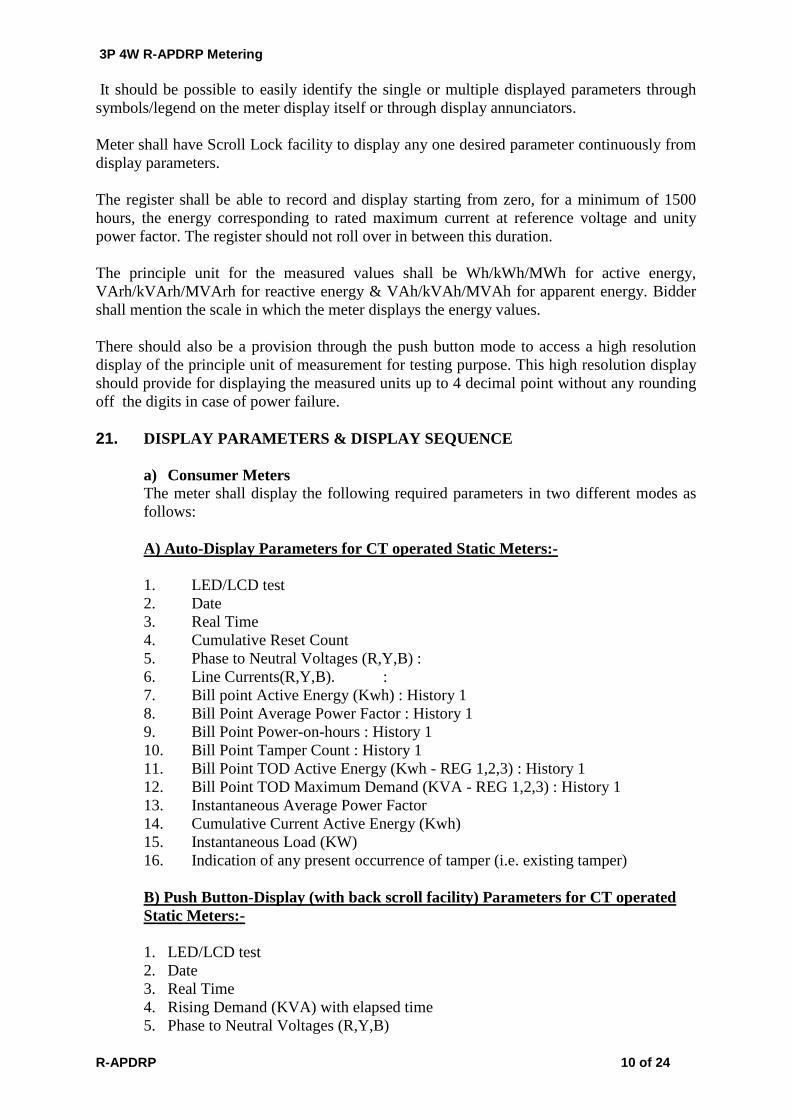
It should be possible to easily identify the single or multiple displayed parameters through symbols/legend on the meter display itself or through display annunciators. Meter shall have Scroll Lock facility to display any one desired parameter continuously from display parameters. The register shall be able to record and display starting from zero, for a minimum of 1500 hours, the energy corresponding to rated maximum current at reference voltage and unity power factor. The register should not roll over in between this duration. The principle unit for the measured values shall be Wh/kWh/MWh for active energy, VArh/kVArh/MVArh for reactive energy & VAh/kVAh/MVAh for apparent energy. Bidder shall mention the scale in which the meter displays the energy values. There should also be a provision through the push button mode to access a high resolution display of the principle unit of measurement for testing purpose. This high resolution display should provide for displaying the measured units up to 4 decimal point without any rounding off the digits in case of power failure. 21. DISPLAY PARAMETERS & DISPLAY SEQUENCE
a) Consumer Meters The meter shall display the following required parameters in two different modes as follows: A) Auto-Display Parameters for CT operated Static Meters:-
1. LED/LCD test 2. Date 3. Real Time 4. Cumulative Reset Count 5. Phase to Neutral Voltages (R,Y,B) : 6. Line Currents(R,Y,B). : 7. Bill point Active Energy (Kwh) : History 1 8. Bill Point Average Power Factor : History 1 9. Bill Point Power-on-hours : History 1 10. Bill Point Tamper Count : History 1 11. Bill Point TOD Active Energy (Kwh - REG 1,2,3) : History 1 12. Bill Point TOD Maximum Demand (KVA - REG 1,2,3) : History 1 13. Instantaneous Average Power Factor 14. Cumulative Current Active Energy (Kwh) 15. Instantaneous Load (KW) 16. Indication of any present occurrence of tamper (i.e. existing tamper) B) Push Button-Display (with back scroll facility) Parameters for CT operated Static Meters:-
1. LED/LCD test 2. Date 3. Real Time 4. Rising Demand (KVA) with elapsed time 5. Phase to Neutral Voltages (R,Y,B)

3P 4W R-APDRP Metering
R-APDRP 11 of 24
6. Line Currents (R,Y,B) : 7. Supply Frequency 8. Instantaneous Power Factor 9. Instantaneous Load, Active, Reactive, Apparent 10. Cumulative Reset Count 11. Bill Point Active Energy (Kwh) : History 1 12. Bill Point Apparent Energy (Kvah): History 1 13. Bill Point Average Power Factor : History 1 14. Bill Point Power-on-hours : History 1 15. Bill Point Tamper Count : History 1 16. Bill Point TOD Active Energy (Kwh - REG 1,2,3) : History 1 17. Bill Point TOD Apparent Energy (Kvah REG 1,2,3) : History 1 18. Bill Point TOD Maximum Demand (KVA - REG 1,2,3) : History 1 19. Cumulative Power-on-hours 20. Cumulative Maximum Demand (KVA 0-24 HRS) 21. Cumulative Current Active Energy (Kwh) 22. Cumulative Current Reactive Lag Energy (Kvarh-Lag) 23. Cumulative Current Reactive Lead Energy (Kvarh-Lead) 24. Cumulative Current Apparent Energy (Kvah) 25. Cumulative Current TOD Active Energy (Kwh - REG 1,2,3) 26. Cumulative Current TOD Apparent Energy (Kvah REG 1,2,3) 27. Current TOD Maximum Demand (KVA - REG 1,2,3) 28. Indication of any existing Tamper 29. Cumulative tamper occurrence counts 30. Tamper information as mentioned in the relevant clauses of the specification
should be recorded and displayed in the push button display 31 Connection Check. C) One high resolution display for Kwh & Kvarh suitable for easy dial testing of the meter. Data Transfer through HHU/CMRI/AMR/LAPTOP: Apart from the display parameters (Auto display & Push Button) as specified above and the standard parameters as specified in the relevant clause of the guideline document, the meter should record in addition the following parameters and all these parameters as well as the displayed parameters should be retrievable/Calculable at the BCS end through CMRI/HHU: 1. Bill Point TOD Reactive Energies (Kvarh) Lag & Lead 2. Current TOD Reactive Energies (Kvarh) Lag & Lead 3. Current Maximum Demand (KVA) ( 0 –24 HRS) 4. Instantaneous power factors of individual phases 5. Bill Point Power factors of individual phases 6. Detail Tamper information 7. Detail historical data of all the parameters for at least 6 calendar months 8. Information regarding following failures:
a) Time & Calendar b) RTC battery c) Segment failure. d) Self diagnostic details e) Battery bad flag
b) Ring Fencing/Boundary/Interface Meters

3P 4W R-APDRP Metering
R-APDRP 12 of 24
The standard parameters as specified in the relevant clause of the guideline document shall be displayed in the auto display mode. Additional parameters if required for the push button mode and BCS mode will be notified in due course prior to ordering. c) Sub-station feeder and DTR meters The standard parameters as specified in the relevant clause of the guideline document shall be displayed in the auto display mode. Additional parameters if required for the push button mode and BCS mode will be notified in due course prior to ordering. However in addition to the daily accounting data, monthly or other periodic figures should also be available.
22. CALIBRATION & TEST OUTPUT All the meters shall be tested, calibrated and sealed at works before dispatch. Further, no modification of calibration shall be possible at site by any means. However, it shall be possible to check the accuracy of energy measurement of the meter while in operation in the field by means of LED test output on meter, accessible from the front as well as through high-resolution display using suitable test equipment. Resolution of the test output shall be sufficient to enable the starting current test in less than 10 minutes. Test output device shall be provided in the form of preferably one common LED for KWh, KVARh and KVAh with provision of selecting the parameter being tested. The test output device should have constant pulse rate in terms of pulse/unit energy. 23. REAL TIME INTERNAL CLOCK (RTC)
RTC shall be pre-programmed for 30 Years day/date without any necessity for correction. The maximum drift shall not exceed +/- 180 Seconds per year. The uncertainty of setting initial time shall not exceed + 30 Seconds with respect to Indian standard time (Ref. NPL New Delhi).
The clock day/date setting and synchronization shall only be possible through password/Key code command from one of the following:
a) Hand Held Unit (HHU) or Meter testing work bench and this shall need password enabling for meter;
b) From remote server through suitable communication network or Sub-station data logger ‘PC’
. 24. DEMAND INTEGRATION & MD REGISTRATION The meter shall continuously monitor and calculate maximum demand for each interval of time, which may be programmable as a block of 15 minutes or 30 minutes as per the user’s choice through the communicating ports as and when required with proper password identification & authentication. At the end of every demand integration period the new calculated MD shall be compared with the previous MD and meter shall store whichever value is higher with date & time stamping. Under the current integration period, the rising demand should be displayed continuously along with the elapsed time. The rising demand with the elapsed time should be held in the memory in the event of interruption or switching off supply and it should not become zero on such instances. The registered demand and the number of times the MD is reset shall also be displayed and the information stored.

3P 4W R-APDRP Metering
R-APDRP 13 of 24
The display of Maximum demand should be as per the provision G-6 of IS 14697 : 1999 25. MD RESET It should also be possible to reset the MD using options. The meter shall have any of the following MD resetting options:
(a) Automatic reset at the end of a certain predefined period by default (24:00 hrs of the last day of the month).
(b) Resetting through a hand held terminal capable of communicating with the meter (i.e.
through HHU with proper password identification & authentication). (c) Communication driven reset form the base terminal/server with proper password
identification and authentication. Note:- It should not be possible to reset the MD by the use of the local push button.
‘ 26. ELECTROMAGNETIC COMPATIBILITY The static energy meters shall conform to requirements listed in relevant standards and shall also be protected against radiated interference from either magnetic or radio-frequency source.
a. IMMUNITY TO ELECTROMAGNETIC DISTURBANCE
The meter shall be designed in such a way that conducted or radiated electromagnetic disturbance as well as electrostatic discharge do not damage or substantially influence the meter and meter shall work satisfactorily under these conditions as per relevant standards
NOTE: the disturbances to be considered are: - (a) Harmonics (b) Voltage dips and short interruptions (c) Conducted transients (d) D.C. and A.C. magnetic fields (e) Electromagnetic HF fields (f) Electrostatic discharges (ESD)
b. RADIO INTERFERENCE SUPPRESSIONS
The meter shall not generate noise, which could interfere with other equipment, and meter shall work satisfactorily as per relevant standards 27. TAMPER & FRAUD MONITORING FEATURES
The meter shall work satisfactorily under presence of various influencing conditions like External Magnetic Field, Electromagnetic Field, Radio Frequency Interference, Vibrations,

3P 4W R-APDRP Metering
R-APDRP 14 of 24
harmonic Distortion, Voltage/Frequency Fluctuations, and electromagnetic High Frequency Fields etc. The meter shall be immune to abnormal voltage/frequency generating devices and shall record the occurrence and restoration of such tamper events along with parameters such as current, voltages, kWh, power factor, event code, date & time etc. (listed in Table A6.1 to A6.8 in the guideline document).
Tamper details shall be stored in internal memory for retrieval by authorized personnel through either of the following:
i) HHU. ii) Remote access through suitable communication network.
Minimum 250 numbers of events (occurrences & restoration with date & time) should be available in the meter memory. The meter shall function properly under following common abnormal conditions:
1. Phase sequence
reversal The meter shall keep working accurately irrespective of the phase sequence of the supply.
2. Missing Neutral The meter shall continue to record accurately according to electrical connections even if the Neutral of potential supply is accidentally or incidentally disconnected.
3. Current reversal / CT polarity reversal
The meter shall log energy in forward direction even if the current is flowing in reverse direction in one or more phases. The meter shall also be capable of detecting and recording occurrence and restoration with date and time if the current is flowing in reverse direction in one or more phases.
4. External magnetic influence
The metering system shall be provided with adequate magnetic shielding so that any external magnetic field (AC Electro Magnet or DC Magnet) as per the values specified in CBIP Technical Report No.88 (with latest amendments) applied on the metering system shall not affect the proper functioning and recording of energy as per error limits prescribed by CBIP.
Beside this the meter should have features to detect the occurrence and restoration of, at least, the following common abnormal events:
a) Missing Potential & Potential imbalance: The meter shall be capable of detecting and recording occurrence and restoration with date and time the cases of Potential failure which could happen due to disconnection of potential leads (one or two), failure of phase line fuse from the Transformer primary side. Meter shall also detect and log cases of voltage unbalance (from 5 % for more than 5 minutes or more- programmable) of voltages.
b) Voltage High / Voltage Low: In case the average 3 phase voltage remains less (below 0.75Vref by default) or more (above 1.15Vref by default) for a predefined period (15 minutes by default), the meter shall log such incidences with date & time. The voltage thresholds & persistence time shall be programmable using the CMRI & BCS. This abnormal condition shall be logged only when all the three-phase voltage is available.

3P 4W R-APDRP Metering
R-APDRP 15 of 24
c) Current imbalance: The meter shall be capable of detecting and recording occurrence and restoration with date and time of Current unbalance (30% or more for more than 15 minutes- programmable).
d) Current Circuit Short: The meter shall be capable of detecting and recording occurrences and restoration of shorting of any one or two phases of current circuit to identify events like CT saturation, CT lead shorting, CT inter turns short etc.
e) Current Circuit Open: The meter shall be capable of detecting and recording occurrences and restoration of opening of any one or two phases of current circuit which can happen due to intentional / accidental disconnection of current circuits. The meter shall be able to log abnormality conditions in current open event like CT leads burns, loose connection, CT winding open etc in the meter memory. No load condition should not be recorded in meter memory as a Current circuit open event.
f) Power on/off: The meter shall be capable to record power on /off events in the meter memory. All potential failure should be record as power off event.
g) High Neutral Current: The meter shall be capable of recording incidences of excess neutral current (if In is in excess of x % of Ib – programmable) .The limits shall be define by the purchaser during the time of final supply.
h) Over load/ low load Hours: The meter shall be capable of recording the over load / low load hours in KVA in the meter memory. The over loads limit shall be in terms of % of Transformer rating in KVA (programmable using HHU & BCS). The over load limits shall be define by the purchaser during the time of final supply.
i) The meter shall also be capable to withstand and shall not get damaged if phase-to-phase voltage is applied between phases to neutral.
The meter shall record the total duration of the above abnormalities, time and date of their occurrences & restorations with a snap shot of electrical conditions viz. Voltage, current, kwh energy, PF etc.
Logic for calculation of voltage and current imbalance shall be furnished by the tenderer.
The meter shall keep records for the minimum last 250 events (occurrence + restoration) for above of abnormal conditions. It shall be possible to retrieve the abnormal event data along with all related snap- shots' data through the meter's optical port or through radio with the help of a hand held unit (HHU) and download the same to the BCS where it shall be available for viewing. All this information shall be made available in simple and easily understandable format.
The above shall be selectable and will be in line with Table A6.8 of GUIDELINE DOCUMENT: Data Exchange for Electricity Meter Reading, Tariff and Load Control – Companion Specification
28. TAMPER LOGIC Properly designed meter event logic should be provided. There shall be separate compartments for logging of potential related event, current related event and power on/off event. The bidder should explain the events details in each compartment under their offer.
3P 4W R-APDRP Metering
R-APDRP 16 of 24
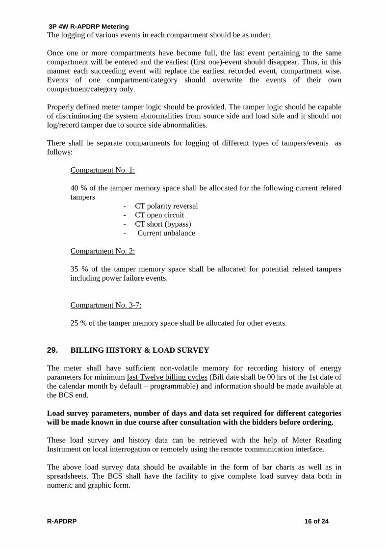
The logging of various events in each compartment should be as under:
Once one or more compartments have become full, the last event pertaining to the same compartment will be entered and the earliest (first one)-event should disappear. Thus, in this manner each succeeding event will replace the earliest recorded event, compartment wise. Events of one compartment/category should overwrite the events of their own compartment/category only.
Properly defined meter tamper logic should be provided. The tamper logic should be capable of discriminating the system abnormalities from source side and load side and it should not log/record tamper due to source side abnormalities.
There shall be separate compartments for logging of different types of tampers/events as follows:
Compartment No. 1: 40 % of the tamper memory space shall be allocated for the following current related tampers
- CT polarity reversal - CT open circuit - CT short (bypass)
- Current unbalance Compartment No. 2: 35 % of the tamper memory space shall be allocated for potential related tampers including power failure events. Compartment No. 3-7: 25 % of the tamper memory space shall be allocated for other events.
29. BILLING HISTORY & LOAD SURVEY
The meter shall have sufficient non-volatile memory for recording history of energy parameters for minimum last Twelve billing cycles (Bill date shall be 00 hrs of the 1st date of the calendar month by default – programmable) and information should be made available at the BCS end. Load survey parameters, number of days and data set required for different categories will be made known in due course after consultation with the bidders before ordering.
These load survey and history data can be retrieved with the help of Meter Reading Instrument on local interrogation or remotely using the remote communication interface.
The above load survey data should be available in the form of bar charts as well as in spreadsheets. The BCS shall have the facility to give complete load survey data both in numeric and graphic form.

3P 4W R-APDRP Metering
R-APDRP 17 of 24
30. TOD METERING PROVISIONS
There shall be a provision up to three Time of Day Zones for Energy (active import, reactive lag while active import & apparent import) and Demand (Apparent demand) registers. TOD provision shall however be as per the guideline document with maximum script identifiers (16) for energy and demand for future use. However at present only three time zones will be used : 06:00 Hrs to 17:00 Hrs, 17:00 Hrs to 22:00 Hrs and 22:00 Hrs to 06:00 Hrs. Number and timing of these TOD Zones shall be user programmable with proper security system. 31. HARMONICS MEASUREMENT THD up to 29th Harmonic shall be measurable that is at sampling rate of 3000/sec. The meter should be capable of measuring fundamental energy as well as total energy. Fundamental energy shall be made available on meter-display and the same only shall be used for billing purpose. TThe total energy shall be logged in the meter memory and be capable of down loading to the BCS through HHU as well as through the remote communication port and be available for analysis at the BCS end. 32. SELF DIAGNOSTIC FEATURE The meter shall be capable of performing complete self-diagnostic check to monitor the circuits for any malfunctioning to ensure integrity of data memory location at all time. The meter shall have indication for unsatisfactory/non-functioning/malfunctioning of the following:
a) Time and date on meter display b) All display segments on meter display c) Real Time Clock (RTC) status in meter reading prints out at BCS end d) Non-volatile Memory (NVM) status in meter reading prints out at BCS end. e) While installing the meter, it should be possible to check the correctness of Current
Transformer, Voltage connections to the meter and their polarity from the functioning of the meter for different voltage injections with the help of vector/phasor diagrams. It should also be possible to check the current and voltage sequence parity. For this purpose suitable software for field diagnosis of meter connections with the help of HHU/Meter Reading Instrument should be supplied.
33. OTHER SALIENT FEATURES OF METERS
a) It should be possible to check the healthiness of phase voltages by displaying all the voltages on the meter display.
b) The meter must be readable in power off condition. For that a battery back-up of suitable capacity shall be provided. Push button for the normal display shall also be used for battery back-up display in power off condition for the manual mode reading of the auto display parameters. It must be possible to power up the battery by means of an external source or by the HHU itself for reading the meter in power off condition by the HHU. In case of an external source an inductive coupling arrangement shall be provided so that it should not be possible to

3P 4W R-APDRP Metering
R-APDRP 18 of 24
damage the circuit of the meter by applying excess voltage directly in the meter. It must also be possible to trigger the battery to power up the meter in case of power failure from the remote server for reading the meter from remote location through the communication ports.
c) The meter should work accurately irrespective of phase sequence of the mains supply
d) The meter should remain powered up and functional even when either of the two phases or one phase along with neutral is available to meter.
e) The meter should continue to record accurately as per prevailing electrical conditions even if the neutral of the potential supply gets disconnected.
34. TEST AND TEST CONDITIONS
Unless specifically waived off, all tests shall be witnessed by the purchaser.
34.1 Type Test
The Energy meter offered shall be fully type tested at any of the NABL accredited test laboratories as per standards indicated in Clause 5 above. That is the meter offered should have successfully passed all type tests described in the IS 14697 and the meter Data Transfer and Communication capability as per the guideline document.
One (1) out of every one thousand (1000) meters or part thereof shall be subjected to the complete range of type tests after final assembly. In case of any failure to pass all specified tests, the bidder shall arrange to carry out the requisite modifications/replacements in the entire lot of meters at his own cost. After any such modifications and final assembly, two (2) meters selected out of the lot by the Owner's representative shall be subjected to the full range of type tests. The Owner shall accept the lot only after successful type testing.
Further Purchaser shall reserve the right to pick up energy meters at random from the lots offered and get the meter tested at third party lab i.e. CPRI / agencies listed at Appendix-C of CBIP publication No-304 / NPL / CQAL/ ERTL / ERDA at the sole discretion of the Purchaser. The supplier has no right to contest the test results of the third party lab or for additional test and has to replace/take corrective action at the cost of the supplier.
It shall be the responsibility of the supplier to arrange such tests and Purchaser shall be informed of the date and time of conduction of tests well in advance to enable him to witness such tests. Test charges of the testing authority, for such successful repeat type tests, shall be reimbursed at actual by the Purchaser.
The meters used for type testing shall be separately identified, duly marked, and supplied to the Owner in case they are fully functional and as good as other (new) meters, after necessary touching up/refurbishing. In case this is not possible, the bidder shall provide their replacements at no extra cost to Owner.

3P 4W R-APDRP Metering
R-APDRP 19 of 24
The Bidder shall arrange all type testing specified above, and bear all expenses for the same.
Type test certificate shall be submitted along with the offer and the same shall not be more than 36 months old at the time of bid submission. Make & type of major components used in the type-tested meter shall be indicated in the QAP.
34.2 Acceptance Test All acceptance tests as per relevant standards shall be carried out in the presence of utility representatives. Additional acceptance shall include Surge withstand (SWC) for 6 kVp, as per IEC 62052-11, Lightning impulse test and HF disturbance test as IS 14697. One sample meter per order from one of the offered lot shall be subjected to SWC/other semi-destructive tests. Meters after tests shall not be used.
Accuracy tests shall be performed at the beginning and at the end of the acceptance tests specified.
34.3 Routine Test All routine tests as specified in table 18 of CBIP Technical Report No. 88 shall be carried out on each individual meter and routine tests certificates shall be submitted for approval of purchaser.
35. QUALITY ASSURANCE:
The manufacturer shall have a comprehensive quality assurance program at all stages of manufacture for ensuring products giving reliable, trouble free performance. Details of the bidder’s quality assurance and test set up shall be furnished with the bid. A detailed quality assurance program shall be finalized with the successful bidder during the award stage. Bidder shall furnish following information along with his bid: i) Organization structure of the manufacturer and his main sub-suppliers (PCBs, SMT
cards, CT/PT) with details of ‘QA’ setup, overall workflow; ii) Copy of system manual showing ‘QAP’ (Quality Assurance Plan) as actually
practiced during manufacturing and final testing. iii) List of raw materials and critical components (ASIC chip, crystal clock, memory
register Chip, transformers, optical ports etc.) with their suppliers; iv) Stage inspection of product before final testing; v) Procedure adopted for ‘In-situ’ testing of PCBs, after placement of surface mounted
component, for quantitative parametric variation of tolerance by self or sub-contractor.
vi) Testing and calibration facility, date of calibration of test bench, manpower data of bench operators;
vii) Sample copies of test certificate of bought out components.
36. QUALIFYING REQUIREMENTS
i) Bidder should be a manufacturer; ii) He should have all the facility in his works for design, assembly, quality
assurance, burn-in test (Fully assembled Energy Meter), testing (all routine and acceptance tests), automatic calibration of Energy Meter on software based test bench, qualified team of technical and software engineers;
3P 4W R-APDRP Metering
R-APDRP 20 of 24
iii) Notwithstanding anything stated herein under, the Purchaser reserves the right to assess the capacity and capability of the bidder to execute the work, should the circumstances warrant such assessment in the overall interest of the Purchaser.
37. GUARANTEE
Equipment (Meter) supplied shall be guaranteed for a period of 66 months from the date of supply Bidders shall guarantee to repair or replace the meters and meter boxes and other accessories, which are found to be defective/ inoperative at the time of installation, or become inoperative/ defective during guarantee period. Replacements shall be effected within 1 month from the date of intimation. The bidder shall extend the guarantee of 5 years. However the backup bank guarantee provided by the bidders shall be valid for 2 years only.
38. FIXING & CONNECTION ARRANGEMENT Manufacturer shall ensure following technical points:
i) Meter shall be suitable for mounting on Simplex type vertical panel with front door; CAT-M4 disconnecting type TBs to be used for Current circuit; Panel wiring to be properly dressed and harnessed; External cables to enter panel from bottom gland plate using double compression glands.(For sub station panel meters only)
. ii) Energy Meter terminals block shall be adequately sized with regard to
maximum conductor dimension, commensurate with current rating of Energy Meter.
39. SOFTWARE
a) Licensed copies of the relevant software shall be made available for installation on each Hand Held Unit (HHU) /Common Meter Reading Instrument (CMRI) and Base computer software (BCS) for installation on the server and other terminals by the supplier.
HHU/Common Meter Reading Instrument (CMRI) would be loaded with user-friendly software (windows based) for reading, downloading meter data and relevant programming transaction in the meter with proper security system.
b) Windows based user interactive Base Computer Software (BCS) shall have to be
supplied for efficient and speedy recovery of data from HHU/CMRI/Meter(by remote communication) and downloading instructions from base computer software to HHU/CMRI/Meter(by remote communication). This BCS should have, amongst other requirements, features and facilities to communicate, download and display meter data as described in the “Guideline document – Data Exchange for Electricity Meter Reading, Tariff and Load Control (Companion Specification for IEC 62056 series of Standards)” from DLMS/COSEM meters. The BCS should also have facility to convert meter reading data into user definable DBF (Access) and spreadsheet format for integrating with the purchaser's billing system. Here again an "Export wizard" or similar utility shall be available whereby user can select file format, the variable data to export, the field width selection of each variable so that it may be possible

3P 4W R-APDRP Metering
R-APDRP 21 of 24
for the user to integrate the same with the user’s billing data and process the selected data in desired manner. The BCS shall also allow for viewing and easy analysis of the meter data acquired and for exporting that data in ASCII or CSV format. It should have in general the following features: i) It shall allow collecting of meter data on direct communication with the meter
through wires as well as through remote system. ii) It shall be possible to view the meter data and details in user friendly manner
(Windows Based Platform). iii) New users with their level of access rights could be defined and managed by
supervisors based upon their usage requirement. iv) It shall be possible to maintain a meter information database, to add, edit,
delete meters from the meter information database with proper authentication. The meter information database shall have amongst others the information relating to meter serial no, meter location, meter status, CT, PT ratios, KVA ratings etc.
v) BCS must have provision to manage users and roles. It shall be possible to create a user and assign him privileges to perform specific types of operation according to the “Role” assigned to him. It shall be possible to define a role and link it with “Rights” of using different options. If rights are not assigned for a particular option, a “User” with that “Role” shall have no right to use or view that option.
vi) The software must have the user friendly GUI and User Interface should be customisable by the user. It shall be possible for a user to a) Display or hide a column in the Meter List Pane b) Change the column width c) Activate & apply column wise filter for displayed list d) Sort the order of the displayed list. The sorting can be enabled on any of
the displayed field / column e) Group the meter list according to a field displayed in a column and then
further sub-group the list according to another field
The software’s shall have the flexibility to generate at least the following sets of reports amongst others
• Energy Accounting reports • Billing Point reports • Load survey reports • Tamper information reports
Billing reports to include customer ID, Name & Address, connected Load, meter
status, billing cycle, historical meter reading, date and time, current meter reading, date and time, Maximum Demand, date and time of Maximum Demand occurrence.
Load survey report for a pre determined time i.e. from ________ date to
___________ date, to include the following.
Customer ID, meter number, Consumer Connectivity references i.e. identity & location of pole / Distribution transformer reference, feeder reference, sub-division reference, division reference, circle reference, time, date, maximum demand (kW),KVAR, kWh, power factor, kVAh, MD reset count, power on hours, outage duration, number of outages, Voltages max R, Y, B date time and duration, Voltages

3P 4W R-APDRP Metering
R-APDRP 22 of 24
minimum R, Y, B date time and duration, load factor as (energy consumed/(maximum demand x power on hours)), average load as (energy consumed / power on hours), TOD max DEMAND and duration, Average current phase wise. The load survey data should be available in the form of bar charts as well as in spreadsheets. The BCS shall have the facility to give complete load survey data both in numeric and graphic form. The exact parameters set and the period for the load survey report for each category of meters will be specified in due course after consultation with the bidders prior to ordering
Tamper reports to include for a pre determined duration or month wise, tamper count, tamper duration and tamper history for each of the meters.
Vendor will provide soft copy of all the software in CD form along with the meters
supplied.
Vendor to install & demonstrate working of software programmes on the HHU/CMRI’s of ASEB
c) Base computer station software for accepting data from hand held unit/CMRI/ for
Processing, generating reports and downloading instructions from the BCS to HHU/CMRI for onward transmission to DLMS/COSEM meters of specific makes, This may include meters of other leading makes.
d) Dial-up software for accepting data from the meter by remote communication
means to the BCS, processing data, & generating reports. SOFTWARE SECURITY The BCS shall have multilevel password for data protection and security. The first level shall allow the user to enter the system. The different software features shall be protected by different passwords. The configurable of passwords shall be user definable. The software installed on one PC shall not be copied on another PC without additional security. HELP SYSTEM Exhaustive online & offline help shall be an integral part of the software so that user can use all the features of the software by pulling down the help contents from the user friendly menus for any references.
40. DATA SECURITY
In addition to the basic security, selective advanced security with encryption and authentication by the use of NIST SP 800-38D as specified in the companion standard guideline document must be provided for. The security system must be adequate enough not to allow data manipulation at any stage. The system should be able to achieve security through authenticated transaction on the HHU/CMRI form the back office software only.

3P 4W R-APDRP Metering
R-APDRP 23 of 24
GUARANTEED TECHNICAL PARTICULARS FOR 3 PHASE 4 WIRE CT PT OPERATED TRIVECTOR ENERGY METER Sl. No.
Item Bidder’s data
1 Type of Meter 2 Application 3 Standard to which the meter confirm 4 Rated Voltage 5 Rated Current 6 Frequency 7 Overload capacity 8 Minimum starting current in % of
base current
9 Power Factor Range 10 Power loss in potential circuit 11 Power loss in current circuit 12 Change in error due to a. Variation in frequency b. Variation in temperature c. Variation in voltage
13 Accuracy Class 14 Type of Energy Registration
Mechanism.
15 MD Reset Mechanism 16 Dynamic Working range a) Voltage b) Current
17 Type of load (linear, non linear, balanced /unbalanced at any P.F.)
18 Total Weight of meter 19 Dimension of the meter 20 Details of meter base & cover 21 Terminal Cover details 22 Capability for fraud Prevention &
detection
23 Sealing and Locking Arrangement 24 Display details i. Display Cycle (descriptive in order
of display sequence) auto and manual
ii. Period of display of each parameter iii. Display scroll-lock facility iv. Backlit LCD v. display off period between two
cycles
vI. No of digits of display and height of character.
25 Memory Capacity 26 Non volatile memory retention
capacity

3P 4W R-APDRP Metering
R-APDRP 24 of 24
27 Powering on facility in absence of mains
28 Tamper data preservation capacity : a) on display b) with meter data downloading
provisions.
29 Tamper logic in detail 30 Load Survey details : a) Parameter measured & Logged b) Logging interval c) No. of days of Load Survey
31 Time of the day Zone Provision 32 Type of communication: a) Local-Optical port details with
protocol
b) Additional Communication port for AMR compatibility with protocol
33 Real Time Clock 34 Self Diagnostic Features (Provide
Details)
35 Certification Marks 41. METER CABINET SPECIFICATIONS: 41.1 The meter cabinet should be made of MS steel plates of minimum thickness 1.2 mm (except for the roof and base). The minimum thickness of the roof and base MS steel plates should be 1.5 mm. 41.2 The meter cabinet should have two doors (one inner and one outer door). The inner
door should hold the optical port for data interchange with external devices. 41.3 The inner box should have an adjustable meter fixing plate which allows forward and backward movement of the meter as per requirement. The modem fixing plates should be installed outside the inner box.
41.4 The base of the outer box should have a gland suitable for insertion of 10 Core, armoured, 2.5sq.mm cable. The doors should have proper high quality rubber gaskets to prevent entry of rain-water, dust etc. 41.5 Both the inner door and outer door should have meter viewing window with high quality
toughened glass. One metallic wired net (2 mm wire) should be provided at the viewing window of the outer door so that in case of break the meter is not accessible to unauthorised people.