specification of rtespecification of rte v2.3.0 r3.1 rev 5 document title specification of rte...
TRANSCRIPT

Specification of RTEV2.3.0
R3.1 Rev 5
Document Title Specification of RTEDocument Owner AUTOSAR
Document Responsibility AUTOSAR
Document Identification No 084
Document Classification Standard
Document Version 2.3.0
Document Status Final
Part of Release 3.1
Revision 5
Document Change HistoryDate Version Changed by Change Description
22.09.2010 2.3.0 AUTOSARAdministration
• Generation of the indirect API de-coupled from multiple instantiation:changed rte sws 1355, rte sws 2613,rte sws 2615.
• Behavior in name clashes of AUTOSARtypes PIM types: added rte sws 5195,changed rte sws 3789, rte sws 3782.
1 of 314— AUTOSAR CONFIDENTIAL —
Document ID 084: AUTOSAR SWS RTE

Specification of RTEV2.3.0
R3.1 Rev 5
27.01.2010 2.2.0 AUTOSARAdministration
• Allow Communication Attributes on Com-positions: changed rte sws in 0055,rte sws in 0062, rte sws in 5023,rte sws in 5050, rte sws in 0067,rte sws in 0029, rte sws in 2701,rte sws in 2693
• Support for initial calibration data val-ues: added rte sws 7186, rte sws 7185,rte sws 2750.
• Reverted implementation of ”‘in-compatible function declarations”’:changed rte sws 1017, rte sws 1018,rte sws 1019, rte sws 1020, rte sws 5107,rte sws 5108, rte sws 5109, rte sws 1254,rte sws 3930, rte sws 3593, rte sws 5512;added rte sws 5195, rte sws 5196,rte sws 5197, rte sws 5198, rte sws 5199,rte sws 5200, rte sws 5201, rte sws 5202,rte sws 5203, rte sws 5204, rte sws 5205,rte sws 5206, rte sws 5207, rte sws 5208,rte sws 5209; removed rte sws 3743; Fixedtypo in rte sws 6129, rte sws 3750 (CalPrmvs. Calprm).
04.02.2009 2.1.0 AUTOSARAdministration
• updated VFB-Tracing:changes rte sws 1327, rte sws 1328
• unconnected R-Ports are supported:changed rte sws 1329, rte sws 3019;added rte sws 1330, rte sws 1331,rte sws 1333, rte sws 1334, rte sws 1336,rte sws 1337, rte sws 1346, rte sws 2621,rte sws 2638, rte sws 2639, rte sws 2640,rte sws 3785, rte sws 5099, rte sws 5100,rte sws 5101, rte sws 5102
• incompatible function declarations:changed rte sws 1018, rte sws 1019,rte sws 1020; added rte sws 5107,rte sws 5108, rte sws 5109; removedrte sws 6030.
• Insufficient RTE server mapping require-ment: changed rte sws 2204.
2 of 314— AUTOSAR CONFIDENTIAL —
Document ID 084: AUTOSAR SWS RTE
Specification of RTEV2.3.0
R3.1 Rev 5
15.02.2008 2.0.1 AUTOSARAdministration
Layout adaptations
20.12.2007 2.0.0 AUTOSARAdministration
• Adapted to new version of meta model
• ”RTE ECU Configuration” added
• Calibration and measurement revised
• Document meta information extended
• Small layout adaptations made
31.01.2007 1.1.1 AUTOSARAdministration
• ”Advice for users” revised
• ”Revision Information” added
01.12.2006 1.1.0 AUTOSARAdministration
Updated for AUTOSAR Release 2.1.
• Adapted to new version of meta model
• New feature ’debouncing of runnable activa-tion’
• New feature ’runnable activation offset’
• ’Measurement and Calibration’ added
• Semantics of implicit communication en-hanced
• Legal disclaimer revised
18.07.2006 1.0.1 AUTOSARAdministration
Second release. Additional features integrated,adapted to updated version of meta-model.
05.05.2006 1.0.0 AUTOSARAdministration
Initial release
3 of 314— AUTOSAR CONFIDENTIAL —
Document ID 084: AUTOSAR SWS RTE

Specification of RTEV2.3.0
R3.1 Rev 5
Disclaimer
This specification and the material contained in it, as released by AUTOSAR is for thepurpose of information only. AUTOSAR and the companies that have contributed to itshall not be liable for any use of the specification.
The material contained in this specification is protected by copyright and other types ofIntellectual Property Rights. The commercial exploitation of the material contained inthis specification requires a license to such Intellectual Property Rights.
This specification may be utilized or reproduced without any modification, in any formor by any means, for informational purposes only. For any other purpose, no part ofthe specification may be utilized or reproduced, in any form or by any means, withoutpermission in writing from the publisher.
The AUTOSAR specifications have been developed for automotive applications only.They have neither been developed, nor tested for non-automotive applications.
The word AUTOSAR and the AUTOSAR logo are registered trademarks.
Advice for users
AUTOSAR Specification Documents may contain exemplary items (exemplary refer-ence models, ”use cases”, and/or references to exemplary technical solutions, devices,processes or software).
Any such exemplary items are contained in the Specification Documents for illustrationpurposes only, and they themselves are not part of the AUTOSAR Standard. Neithertheir presence in such Specification Documents, nor any later documentation of AU-TOSAR conformance of products actually implementing such exemplary items, implythat intellectual property rights covering such exemplary items are licensed under thesame rules as applicable to the AUTOSAR Standard.
4 of 314— AUTOSAR CONFIDENTIAL —
Document ID 084: AUTOSAR SWS RTE

Specification of RTEV2.3.0
R3.1 Rev 5
Table of Contents
1 Introduction 14
1.1 Scope . . . . . . . . . . . . . . . . . . . . . . . . . . . . . . . . . . . . . 141.2 Dependency to other AUTOSAR specifications . . . . . . . . . . . . . . 151.3 Acronyms and Abbreviations . . . . . . . . . . . . . . . . . . . . . . . . 161.4 Technical Terms . . . . . . . . . . . . . . . . . . . . . . . . . . . . . . . 161.5 Document Conventions . . . . . . . . . . . . . . . . . . . . . . . . . . . 171.6 Requirements Traceability . . . . . . . . . . . . . . . . . . . . . . . . . . 18
2 RTE Overview 28
2.1 The RTE in the Context of AUTOSAR . . . . . . . . . . . . . . . . . . . 282.2 AUTOSAR Concepts . . . . . . . . . . . . . . . . . . . . . . . . . . . . . 28
2.2.1 AUTOSAR Software-components . . . . . . . . . . . . . . . . . . 282.2.2 Basic Software Modules . . . . . . . . . . . . . . . . . . . . . . . 292.2.3 Communication . . . . . . . . . . . . . . . . . . . . . . . . . . . . 29
2.2.3.1 Communication Models . . . . . . . . . . . . . . . . . . 292.2.3.2 Communication Modes . . . . . . . . . . . . . . . . . . 302.2.3.3 Static Communication . . . . . . . . . . . . . . . . . . . 302.2.3.4 Multiplicity . . . . . . . . . . . . . . . . . . . . . . . . . 30
2.2.4 Concurrency . . . . . . . . . . . . . . . . . . . . . . . . . . . . . 312.3 The RTE Generator . . . . . . . . . . . . . . . . . . . . . . . . . . . . . 322.4 Design Decisions . . . . . . . . . . . . . . . . . . . . . . . . . . . . . . . 32
3 RTE Generation Process 34
3.1 RTE Contract Phase . . . . . . . . . . . . . . . . . . . . . . . . . . . . . 363.2 RTE Configuration Editing . . . . . . . . . . . . . . . . . . . . . . . . . . 373.3 RTE Generation Phase . . . . . . . . . . . . . . . . . . . . . . . . . . . 383.4 RTE Configuration and OS Interaction . . . . . . . . . . . . . . . . . . . 38
4 RTE Functional Specification 41
4.1 Architectural concepts . . . . . . . . . . . . . . . . . . . . . . . . . . . . 414.1.1 Scope . . . . . . . . . . . . . . . . . . . . . . . . . . . . . . . . . 414.1.2 RTE and AUTOSAR Software-Components . . . . . . . . . . . . 41
4.1.2.1 Structure of SW-Components . . . . . . . . . . . . . . 424.1.2.2 Ports, Interfaces and Connections . . . . . . . . . . . . 424.1.2.3 Internal Behavior . . . . . . . . . . . . . . . . . . . . . . 444.1.2.4 Implementation . . . . . . . . . . . . . . . . . . . . . . 46
4.1.3 Instantiation . . . . . . . . . . . . . . . . . . . . . . . . . . . . . . 474.1.3.1 Scope and background . . . . . . . . . . . . . . . . . . 474.1.3.2 Concepts of instantiation . . . . . . . . . . . . . . . . . 484.1.3.3 Single instantiation . . . . . . . . . . . . . . . . . . . . 494.1.3.4 Multiple instantiation . . . . . . . . . . . . . . . . . . . . 49
4.1.4 RTE and AUTOSAR Services . . . . . . . . . . . . . . . . . . . . 504.1.5 RTE and ECU Abstraction . . . . . . . . . . . . . . . . . . . . . . 514.1.6 RTE and Complex Device Driver . . . . . . . . . . . . . . . . . . 52
5 of 314— AUTOSAR CONFIDENTIAL —
Document ID 084: AUTOSAR SWS RTE

Specification of RTEV2.3.0
R3.1 Rev 5
4.2 RTE Implementation Aspects . . . . . . . . . . . . . . . . . . . . . . . . 524.2.1 Scope . . . . . . . . . . . . . . . . . . . . . . . . . . . . . . . . . 524.2.2 OS . . . . . . . . . . . . . . . . . . . . . . . . . . . . . . . . . . . 54
4.2.2.1 OS Objects . . . . . . . . . . . . . . . . . . . . . . . . . 544.2.2.2 Runnable Entities . . . . . . . . . . . . . . . . . . . . . 564.2.2.3 RTE Events . . . . . . . . . . . . . . . . . . . . . . . . 574.2.2.4 Mapping of runnable entities to tasks . . . . . . . . . . 584.2.2.5 Activation Offset for runnable . . . . . . . . . . . . . . . 664.2.2.6 Activation and Start of Runnable Entities . . . . . . . . 68
4.2.3 Interrupt decoupling and notifications . . . . . . . . . . . . . . . 714.2.3.1 Basic notification principles . . . . . . . . . . . . . . . . 714.2.3.2 Interrupts . . . . . . . . . . . . . . . . . . . . . . . . . . 724.2.3.3 Decoupling interrupts on RTE level . . . . . . . . . . . 734.2.3.4 RTE and interrupt categories . . . . . . . . . . . . . . . 74
4.2.4 Data Consistency . . . . . . . . . . . . . . . . . . . . . . . . . . 744.2.4.1 General . . . . . . . . . . . . . . . . . . . . . . . . . . . 744.2.4.2 Communications to look at . . . . . . . . . . . . . . . . 764.2.4.3 Concepts . . . . . . . . . . . . . . . . . . . . . . . . . . 764.2.4.4 Mechanisms to guarantee data consistency . . . . . . . 774.2.4.5 Exclusive Areas . . . . . . . . . . . . . . . . . . . . . . 804.2.4.6 InterRunnableVariables . . . . . . . . . . . . . . . . . . 82
4.2.5 Multiple trigger of Runnables . . . . . . . . . . . . . . . . . . . . 854.2.6 Measurement and Calibration . . . . . . . . . . . . . . . . . . . . 86
4.2.6.1 General . . . . . . . . . . . . . . . . . . . . . . . . . . . 864.2.6.2 Measurement . . . . . . . . . . . . . . . . . . . . . . . 874.2.6.3 Calibration . . . . . . . . . . . . . . . . . . . . . . . . . 92
4.3 Communication Models . . . . . . . . . . . . . . . . . . . . . . . . . . . 1074.3.1 Sender-Receiver . . . . . . . . . . . . . . . . . . . . . . . . . . . 107
4.3.1.1 Introduction . . . . . . . . . . . . . . . . . . . . . . . . . 1074.3.1.2 Receive Modes . . . . . . . . . . . . . . . . . . . . . . 1084.3.1.3 Multiple Data Elements . . . . . . . . . . . . . . . . . . 1104.3.1.4 Multiple Receivers and Senders . . . . . . . . . . . . . 1124.3.1.5 Implicit and Explicit Data Reception and Transmission . 1124.3.1.6 Transmission Acknowledgement . . . . . . . . . . . . . 1174.3.1.7 Communication Time-out . . . . . . . . . . . . . . . . . 1194.3.1.8 Data Element Invalidation . . . . . . . . . . . . . . . . . 1204.3.1.9 Filters . . . . . . . . . . . . . . . . . . . . . . . . . . . . 1224.3.1.10 Buffering . . . . . . . . . . . . . . . . . . . . . . . . . . 1224.3.1.11 Operation . . . . . . . . . . . . . . . . . . . . . . . . . . 123
4.3.2 Client-Server . . . . . . . . . . . . . . . . . . . . . . . . . . . . . 1314.3.2.1 Introduction . . . . . . . . . . . . . . . . . . . . . . . . . 1314.3.2.2 Multiplicity . . . . . . . . . . . . . . . . . . . . . . . . . 1324.3.2.3 Communication Time-out . . . . . . . . . . . . . . . . . 1344.3.2.4 Port-Defined argument values . . . . . . . . . . . . . . 1354.3.2.5 Buffering . . . . . . . . . . . . . . . . . . . . . . . . . . 1364.3.2.6 Inter ECU Response to Request Mapping . . . . . . . . 137
6 of 314— AUTOSAR CONFIDENTIAL —
Document ID 084: AUTOSAR SWS RTE

Specification of RTEV2.3.0
R3.1 Rev 5
4.3.2.7 Operation . . . . . . . . . . . . . . . . . . . . . . . . . . 1394.3.3 SWC internal communication . . . . . . . . . . . . . . . . . . . . 144
4.3.3.1 InterRunnableVariables . . . . . . . . . . . . . . . . . . 1444.4 Modes . . . . . . . . . . . . . . . . . . . . . . . . . . . . . . . . . . . . . 145
4.4.1 Mode User . . . . . . . . . . . . . . . . . . . . . . . . . . . . . . 1454.4.2 Mode Manager . . . . . . . . . . . . . . . . . . . . . . . . . . . . 1474.4.3 Refinement of the semantics of ModeDeclarations and Mode-
DeclarationGroups . . . . . . . . . . . . . . . . . . . . . . . . . . 1484.4.4 Order of actions taken by the RTE upon interception of a mode
switch notification . . . . . . . . . . . . . . . . . . . . . . . . . . 1484.4.5 Notification of mode switches . . . . . . . . . . . . . . . . . . . . 152
4.5 Initialization and Finalization . . . . . . . . . . . . . . . . . . . . . . . . . 1554.5.1 Initialization and Finalization of the RTE . . . . . . . . . . . . . . 1554.5.2 Initialization and Finalization of AUTOSAR Software-Components 155
4.6 RTE Functionality Levels . . . . . . . . . . . . . . . . . . . . . . . . . . . 156
5 RTE Reference 157
5.1 Scope . . . . . . . . . . . . . . . . . . . . . . . . . . . . . . . . . . . . . 1575.1.1 Programming Languages . . . . . . . . . . . . . . . . . . . . . . 1575.1.2 Generator Principles . . . . . . . . . . . . . . . . . . . . . . . . . 158
5.1.2.1 Operating Modes . . . . . . . . . . . . . . . . . . . . . 1585.1.2.2 Optimization Modes . . . . . . . . . . . . . . . . . . . . 159
5.1.3 Generator external configuration switches . . . . . . . . . . . . . 1605.2 API Principles . . . . . . . . . . . . . . . . . . . . . . . . . . . . . . . . . 160
5.2.1 RTE Namespace . . . . . . . . . . . . . . . . . . . . . . . . . . . 1615.2.2 Direct API . . . . . . . . . . . . . . . . . . . . . . . . . . . . . . . 1615.2.3 Indirect API . . . . . . . . . . . . . . . . . . . . . . . . . . . . . . 162
5.2.3.1 Accessing Port Handles . . . . . . . . . . . . . . . . . . 1625.2.4 DataReadAccess and DataWriteAccess . . . . . . . . . . . . . . 1635.2.5 PerInstanceMemory . . . . . . . . . . . . . . . . . . . . . . . . . 1645.2.6 API Mapping . . . . . . . . . . . . . . . . . . . . . . . . . . . . . 166
5.2.6.1 “RTE Contract” Phase . . . . . . . . . . . . . . . . . . . 1675.2.6.2 “RTE Generation” Phase . . . . . . . . . . . . . . . . . 1685.2.6.3 Function Elidation . . . . . . . . . . . . . . . . . . . . . 1685.2.6.4 API Naming Conventions . . . . . . . . . . . . . . . . . 1695.2.6.5 API Parameters . . . . . . . . . . . . . . . . . . . . . . 1705.2.6.6 Error Handling . . . . . . . . . . . . . . . . . . . . . . . 1745.2.6.7 Success Feedback . . . . . . . . . . . . . . . . . . . . 175
5.2.7 Unconnected Ports . . . . . . . . . . . . . . . . . . . . . . . . . . 1755.2.7.1 Data Elements . . . . . . . . . . . . . . . . . . . . . . . 1765.2.7.2 Mode Ports . . . . . . . . . . . . . . . . . . . . . . . . . 1775.2.7.3 Client-Server . . . . . . . . . . . . . . . . . . . . . . . . 178
5.2.8 Non-identical ports . . . . . . . . . . . . . . . . . . . . . . . . . . 1785.3 RTE Modules . . . . . . . . . . . . . . . . . . . . . . . . . . . . . . . . . 179
5.3.1 RTE Header File . . . . . . . . . . . . . . . . . . . . . . . . . . . 1795.3.2 Lifecycle Header File . . . . . . . . . . . . . . . . . . . . . . . . . 180
7 of 314— AUTOSAR CONFIDENTIAL —
Document ID 084: AUTOSAR SWS RTE

Specification of RTEV2.3.0
R3.1 Rev 5
5.3.3 Application Header File . . . . . . . . . . . . . . . . . . . . . . . 1805.3.3.1 File Name . . . . . . . . . . . . . . . . . . . . . . . . . 1815.3.3.2 Scope . . . . . . . . . . . . . . . . . . . . . . . . . . . . 1815.3.3.3 File Contents . . . . . . . . . . . . . . . . . . . . . . . . 182
5.3.4 AUTOSAR Types Header File . . . . . . . . . . . . . . . . . . . . 1845.3.4.1 File Contents . . . . . . . . . . . . . . . . . . . . . . . . 1845.3.4.2 Primitive AUTOSAR Data Types . . . . . . . . . . . . . 1845.3.4.3 Complex AUTOSAR Data Types . . . . . . . . . . . . . 1865.3.4.4 C/C++ . . . . . . . . . . . . . . . . . . . . . . . . . . . . 188
5.3.5 VFB Tracing Header File . . . . . . . . . . . . . . . . . . . . . . . 1885.3.5.1 C/C++ . . . . . . . . . . . . . . . . . . . . . . . . . . . . 1885.3.5.2 File Contents . . . . . . . . . . . . . . . . . . . . . . . . 188
5.3.6 RTE Configuration Header File . . . . . . . . . . . . . . . . . . . 1905.3.6.1 C/C++ . . . . . . . . . . . . . . . . . . . . . . . . . . . . 1905.3.6.2 File Contents . . . . . . . . . . . . . . . . . . . . . . . . 190
5.3.7 Generated RTE . . . . . . . . . . . . . . . . . . . . . . . . . . . . 1915.3.7.1 Header File Usage . . . . . . . . . . . . . . . . . . . . . 1915.3.7.2 C/C++ . . . . . . . . . . . . . . . . . . . . . . . . . . . . 1925.3.7.3 File Contents . . . . . . . . . . . . . . . . . . . . . . . . 1925.3.7.4 Reentrancy . . . . . . . . . . . . . . . . . . . . . . . . . 194
5.4 RTE Data Structures . . . . . . . . . . . . . . . . . . . . . . . . . . . . . 1945.4.1 Instance Handle . . . . . . . . . . . . . . . . . . . . . . . . . . . 1945.4.2 Component Data Structure . . . . . . . . . . . . . . . . . . . . . 195
5.4.2.1 Data Handles Section . . . . . . . . . . . . . . . . . . . 1975.4.2.2 Per-instance Memory Handles Section . . . . . . . . . 1995.4.2.3 Inter Runnable Variable Handles Section . . . . . . . . 2005.4.2.4 Exclusive-area handles Section . . . . . . . . . . . . . 2005.4.2.5 Port API Section . . . . . . . . . . . . . . . . . . . . . . 2015.4.2.6 Calibration Parameter Handles Section . . . . . . . . . 2055.4.2.7 Inter Runnable Variable API Section . . . . . . . . . . . 2055.4.2.8 Vendor Specific Section . . . . . . . . . . . . . . . . . . 206
5.5 API Data Types . . . . . . . . . . . . . . . . . . . . . . . . . . . . . . . . 2065.5.1 Std ReturnType . . . . . . . . . . . . . . . . . . . . . . . . . . . . 206
5.5.1.1 Infrastructure Errors . . . . . . . . . . . . . . . . . . . . 2085.5.1.2 Application Errors . . . . . . . . . . . . . . . . . . . . . 2085.5.1.3 Predefined Error Codes . . . . . . . . . . . . . . . . . . 209
5.5.2 Rte Instance . . . . . . . . . . . . . . . . . . . . . . . . . . . . . 2115.5.3 RTE Modes . . . . . . . . . . . . . . . . . . . . . . . . . . . . . . 2115.5.4 Enumeration Data Types . . . . . . . . . . . . . . . . . . . . . . 2125.5.5 Range Data Types . . . . . . . . . . . . . . . . . . . . . . . . . . 213
5.6 API Reference . . . . . . . . . . . . . . . . . . . . . . . . . . . . . . . . 2135.6.1 Rte Ports . . . . . . . . . . . . . . . . . . . . . . . . . . . . . . . 2145.6.2 Rte NPorts . . . . . . . . . . . . . . . . . . . . . . . . . . . . . . 2145.6.3 Rte Port . . . . . . . . . . . . . . . . . . . . . . . . . . . . . . . . 2155.6.4 Rte Send/Rte Write . . . . . . . . . . . . . . . . . . . . . . . . . 2155.6.5 Rte Switch . . . . . . . . . . . . . . . . . . . . . . . . . . . . . . 217
8 of 314— AUTOSAR CONFIDENTIAL —
Document ID 084: AUTOSAR SWS RTE

Specification of RTEV2.3.0
R3.1 Rev 5
5.6.6 Rte Invalidate . . . . . . . . . . . . . . . . . . . . . . . . . . . . . 2185.6.7 Rte Feedback . . . . . . . . . . . . . . . . . . . . . . . . . . . . 2195.6.8 Rte Read . . . . . . . . . . . . . . . . . . . . . . . . . . . . . . . 2225.6.9 Rte Receive . . . . . . . . . . . . . . . . . . . . . . . . . . . . . 2235.6.10 Rte Call . . . . . . . . . . . . . . . . . . . . . . . . . . . . . . . . 2245.6.11 Rte Result . . . . . . . . . . . . . . . . . . . . . . . . . . . . . . 2265.6.12 Rte Pim . . . . . . . . . . . . . . . . . . . . . . . . . . . . . . . . 2285.6.13 Rte CData . . . . . . . . . . . . . . . . . . . . . . . . . . . . . . 2295.6.14 Rte Calprm . . . . . . . . . . . . . . . . . . . . . . . . . . . . . . 2295.6.15 Rte IRead . . . . . . . . . . . . . . . . . . . . . . . . . . . . . . . 2305.6.16 Rte IWrite . . . . . . . . . . . . . . . . . . . . . . . . . . . . . . . 2315.6.17 Rte IWriteRef . . . . . . . . . . . . . . . . . . . . . . . . . . . . . 2325.6.18 Rte IInvalidate . . . . . . . . . . . . . . . . . . . . . . . . . . . . 2335.6.19 Rte IStatus . . . . . . . . . . . . . . . . . . . . . . . . . . . . . . 2345.6.20 Rte IrvIRead . . . . . . . . . . . . . . . . . . . . . . . . . . . . . 2355.6.21 Rte IrvIWrite . . . . . . . . . . . . . . . . . . . . . . . . . . . . . 2365.6.22 Rte IrvRead . . . . . . . . . . . . . . . . . . . . . . . . . . . . . . 2375.6.23 Rte IrvWrite . . . . . . . . . . . . . . . . . . . . . . . . . . . . . . 2385.6.24 Rte Enter . . . . . . . . . . . . . . . . . . . . . . . . . . . . . . . 2385.6.25 Rte Exit . . . . . . . . . . . . . . . . . . . . . . . . . . . . . . . . 2395.6.26 Rte Mode . . . . . . . . . . . . . . . . . . . . . . . . . . . . . . . 240
5.7 Runnable Entity Reference . . . . . . . . . . . . . . . . . . . . . . . . . 2415.7.1 Signature . . . . . . . . . . . . . . . . . . . . . . . . . . . . . . . 2415.7.2 Entry Point Prototype . . . . . . . . . . . . . . . . . . . . . . . . 2415.7.3 Role Parameters . . . . . . . . . . . . . . . . . . . . . . . . . . . 2425.7.4 Return Value . . . . . . . . . . . . . . . . . . . . . . . . . . . . . 2425.7.5 Triggering Events . . . . . . . . . . . . . . . . . . . . . . . . . . . 242
5.7.5.1 TimingEvent . . . . . . . . . . . . . . . . . . . . . . . . 2435.7.5.2 ModeSwitchEvent . . . . . . . . . . . . . . . . . . . . . 2435.7.5.3 AsynchronousServerCallReturnsEvent . . . . . . . . . 2435.7.5.4 DataReceiveErrorEvent . . . . . . . . . . . . . . . . . . 2435.7.5.5 OperationInvokedEvent . . . . . . . . . . . . . . . . . . 2445.7.5.6 DataReceivedEvent . . . . . . . . . . . . . . . . . . . . 2455.7.5.7 DataSendCompletedEvent . . . . . . . . . . . . . . . . 245
5.7.6 Reentrancy . . . . . . . . . . . . . . . . . . . . . . . . . . . . . . 2455.8 RTE Lifecycle API Reference . . . . . . . . . . . . . . . . . . . . . . . . 246
5.8.1 Rte Start . . . . . . . . . . . . . . . . . . . . . . . . . . . . . . . 2465.8.2 Rte Stop . . . . . . . . . . . . . . . . . . . . . . . . . . . . . . . 247
5.9 RTE Call-backs Reference . . . . . . . . . . . . . . . . . . . . . . . . . . 2485.9.1 RTE-COM Message Naming Conventions . . . . . . . . . . . . . 2485.9.2 Communication Service Call-backs . . . . . . . . . . . . . . . . . 2485.9.3 Naming convention of CallbackRoutineName . . . . . . . . . . . 249
5.10 VFB Tracing Reference . . . . . . . . . . . . . . . . . . . . . . . . . . . 2505.10.1 Prinicple of Operation . . . . . . . . . . . . . . . . . . . . . . . . 2515.10.2 Trace Events . . . . . . . . . . . . . . . . . . . . . . . . . . . . . 251
5.10.2.1 RTE API Trace Events . . . . . . . . . . . . . . . . . . . 251
9 of 314— AUTOSAR CONFIDENTIAL —
Document ID 084: AUTOSAR SWS RTE

Specification of RTEV2.3.0
R3.1 Rev 5
5.10.2.2 COM Trace Events . . . . . . . . . . . . . . . . . . . . . 2525.10.2.3 OS Trace Events . . . . . . . . . . . . . . . . . . . . . . 2535.10.2.4 Runnable Entity Trace Events . . . . . . . . . . . . . . 255
5.10.3 Configuration . . . . . . . . . . . . . . . . . . . . . . . . . . . . . 2565.10.4 Interaction with Object-code Software-Components . . . . . . . 256
6 RTE ECU Configuration 257
6.1 RTE Generation Parameters . . . . . . . . . . . . . . . . . . . . . . . . 2606.2 Handling of Software Component instances . . . . . . . . . . . . . . . . 263
6.2.1 Selection of SW-Component Implementation . . . . . . . . . . . 2646.2.2 Runnable Entity to task mapping . . . . . . . . . . . . . . . . . . 2656.2.3 Exclusive Area implementation . . . . . . . . . . . . . . . . . . . 2686.2.4 NVRam Allocation . . . . . . . . . . . . . . . . . . . . . . . . . . 270
6.3 Component Type Calibration . . . . . . . . . . . . . . . . . . . . . . . . 2726.4 Communication infrastructure . . . . . . . . . . . . . . . . . . . . . . . . 273
A Metamodel Restrictions 274
A.1 Restriction concerning WaitPoint . . . . . . . . . . . . . . . . . . . . . . 274A.2 Restriction concerning RTEEvent . . . . . . . . . . . . . . . . . . . . . . 274A.3 Restriction concerning isQueued attribute of DataElementPrototype . . 275A.4 Restriction concerning ServerCallPoint . . . . . . . . . . . . . . . . . . . 275A.5 Restriction concerning multiple instantiation of software components . . 276A.6 Restriction concerning runnable entity . . . . . . . . . . . . . . . . . . . 276A.7 Restrictions concerning runnables with dependencies on modes . . . . 276A.8 Restriction concerning InterRunnableVariables . . . . . . . . . . . . . . 278A.9 Restriction concerning InternalBehavior . . . . . . . . . . . . . . . . . . 278A.10 Restriction concerning Initial Value . . . . . . . . . . . . . . . . . . . . . 279A.11 Restriction concerning PerInstanceMemory . . . . . . . . . . . . . . . . 279A.12 Restriction concerning unconnected r-port . . . . . . . . . . . . . . . . . 279A.13 Restrictions regarding n:1 sender-receiver communication . . . . . . . . 280A.14 Restrictions regarding Measurement and Calibration . . . . . . . . . . . 280A.15 Restriction concerning ExclusiveAreaImplMechanism . . . . . . . . . . 280
B Required Input Information 282
B.1 SWC and instance . . . . . . . . . . . . . . . . . . . . . . . . . . . . . . 282B.2 Runnable entity and task . . . . . . . . . . . . . . . . . . . . . . . . . . 286B.3 Port and interface . . . . . . . . . . . . . . . . . . . . . . . . . . . . . . . 291B.4 Communication . . . . . . . . . . . . . . . . . . . . . . . . . . . . . . . . 299B.5 Data consistency . . . . . . . . . . . . . . . . . . . . . . . . . . . . . . . 301B.6 RTE configuration . . . . . . . . . . . . . . . . . . . . . . . . . . . . . . 303B.7 Measurement and calibration . . . . . . . . . . . . . . . . . . . . . . . . 305B.8 Mode management . . . . . . . . . . . . . . . . . . . . . . . . . . . . . . 306
C External Requirements 310
D MISRA C Compliance 312
10 of 314— AUTOSAR CONFIDENTIAL —
Document ID 084: AUTOSAR SWS RTE

Specification of RTEV2.3.0
R3.1 Rev 5
E Interfaces of COM used by the RTE 313
11 of 314— AUTOSAR CONFIDENTIAL —
Document ID 084: AUTOSAR SWS RTE
Specification of RTEV2.3.0
R3.1 Rev 5
Bibliography
[1] GlossaryAUTOSAR Glossary.pdf
[2] MethodologyAUTOSAR Methodology.pdf
[3] Requirements on CommunicationAUTOSAR SRS COM.pdf
[4] Requirements on ECU ConfigurationAUTOSAR RS ECU Configuration.pdf
[5] Requirements on Operating SystemAUTOSAR SRS OS.pdf
[6] Specification of CommunicationAUTOSAR SWS COM.pdf
[7] Specification of ECU ConfigurationAUTOSAR ECU Configuration.pdf
[8] Specification of ECU State ManagerAUTOSAR SWS ECU StateManager.pdf
[9] Specification of Interoperability of Authoring ToolsAUTOSAR InteroperabilityAuthoringTools.pdf
[10] Specification of I/O Hardware AbstractionAUTOSAR SWS IO HWAbstraction.pdf
[11] Specification of Operating SystemAUTOSAR SWS OS.pdf
[12] Specification of Standard TypesAUTOSAR SWS StandardTypes.pdf
[13] Specification of the Virtual Functional Bus
12 of 314— AUTOSAR CONFIDENTIAL —
Document ID 084: AUTOSAR SWS RTE

Specification of RTEV2.3.0
R3.1 Rev 5
AUTOSAR VirtualFunctionBus.pdf
[14] Specification of System TemplateAUTOSAR SystemTemplate.pdf
[15] DTD FileAUTOSAR DTD File.dtd
[16] Template Modeling GuideAUTOSAR TemplateModelingGuide.pdf
[17] Software Component TemplateAUTOSAR SoftwareComponentTemplate.pdf
[18] Gemeinsames Subset der MISRA C Guidelineshttp://www.automotive-his.de/download/HIS SubSet MISRA C 1.0.3.pdf
13 of 314— AUTOSAR CONFIDENTIAL —
Document ID 084: AUTOSAR SWS RTE

Specification of RTEV2.3.0
R3.1 Rev 5
Note on XML examplesThis specification includes examples in XML based on the AUTOSAR metamodel avail-able at the time of writing. These examples are included as illustrations of configura-tions and their expected outcome but should not be considered part of the specification.
1 Introduction
This document contains the software specification of the AUTOSAR Run-Time Envi-ronment (RTE). Basically, the RTE together with the OS, AUTOSAR COM and otherBasic Software Modules is the implementation of the Virtual Functional Bus concepts(VFB, [13]). The RTE implements the AUTOSAR Virtual Functional Bus interfaces andthereby realizes the communication between AUTOSAR software-components.
This document describes how these concepts are realized within the RTE. Further-more, the Application Programming Interface (API) of the RTE and the interaction ofthe RTE with other basic software modules is specified.
1.1 Scope
This document is intended to be the main reference for developers of an RTE gener-ator tool or of a concrete RTE implementation respectively. The document is also thereference for developers of AUTOSAR software-components and basic software mod-ules that interact with the RTE, since it specifies the application programming interfaceof the RTE and therefore the mechanisms for accessing the RTE functionality. Fur-thermore, this specification should be read by the AUTOSAR working groups that areclosely related to the RTE (see Section 1.2 below), since it describes the interfaces ofthe RTE to these modules as well as the behavior / functionality the RTE expects fromthem.
This document is structured as follows. After this general introduction, Chapter 2 givesa more detailed introduction of the concepts of the RTE. Chapter 3 describes how anRTE is generated in the context of the overall AUTOSAR methodology. Chapter 4 isthe central part of this document. It specifies the RTE functionality in detail. The RTEAPI is described in Chapter 5.
The appendix of this document consists of five parts: Appendix A lists the restrictions tothe AUTOSAR metamodel that this version of the RTE specification relies on. AppendixB describes the input that is needed for the RTE generation process and where thisinput is assumed to come from. Appendix C explicitly lists all external requirements, i.e.all requirements that are not about the RTE itself but specify the assumptions on theenvironment and the input of an RTE generator. In Appendix D some HIS MISRA rulesare listed that are likely to be violated by RTE code, and the rationale why these vio-lations may occur. Finally, Appendix E lists the COM API and COM Callback functionsthat are used by the RTE
14 of 314— AUTOSAR CONFIDENTIAL —
Document ID 084: AUTOSAR SWS RTE

Specification of RTEV2.3.0
R3.1 Rev 5
Note that Chapters 1 and 2, as well as Appendix D and E do not contain any require-ments and are thus intended for information only.
Chapters 4, 5, and Appendix B are are probably of most interest for developers of anRTE Generator. Chapters 2, 3, 5 are important for developers of AUTOSAR software-components and basic software modules. The most important chapters for relatedAUTOSAR work packages would be Chapters 4 and 5, as well as Appendix B and C.
The specifications in this document do not define details of the implementation of aconcrete RTE or RTE generator respectively. Furthermore, aspects of the ECU- andsystem-generation process (like e.g. the mapping of SW-Cs to ECUs, or schedulabilityanalysis) are also not in the scope of this specification. Nevertheless, it is specifiedwhat input the RTE generator expects from these configuration phases.
1.2 Dependency to other AUTOSAR specifications
The main documents that served as input for the specification of the RTE are the spec-ification of the Virtual Functional Bus [13] and the specification of the Software Com-ponent Template [17]. Also of primary importance are the specifications of those BasicSoftware modules that closely interact with the RTE (or vice versa). These are espe-cially the communication module [6] and the operating system [11]. The main input ofan RTE generator is described (among others) in the ECU Configuration Description.Therefore, the corresponding specification [4] is also important for the RTE specifica-tion. Furthermore, as the process of RTE generation is an important part of the overallAUTOSAR Methodology, the corresponding document [2] is also considered.
The following list shows the specifications that are closely interdependent to the speci-fication of the RTE:
• Specification of the Virtual Functional Bus [13]
• Specification of the Software Component Template [17]
• Specification of AUTOSAR COM [6]
• Specification of AUTOSAR OS [11]
• Specification of ECU State Manager and Communication Manager [8]
• Specification of ECU-Configuration Description / Generation [4]
• Specification of System Description / Generation [14]
• AUTOSAR Methodology [2]
• Documents relevant for the AUTOSAR Metamodel [16, 15]
15 of 314— AUTOSAR CONFIDENTIAL —
Document ID 084: AUTOSAR SWS RTE

Specification of RTEV2.3.0
R3.1 Rev 5
1.3 Acronyms and Abbreviations
All abbreviations used throughout this document – except the ones listed here – canbe found in the official AUTOSAR glossary [1].
1.4 Technical Terms
All technical terms used throughout this document – except the ones listed here – canbe found in the official AUTOSAR glossary [1] or the Software Component TemplateSpecification [17].
Term Description
mode switch interface
A SenderReceiverInterface with a ModeDeclara-tionGroupPrototype of a ModeDeclarationGroup iscalled mode switch interface for the ModeDeclaration-Group. The mode ports of the mode manager andthe mode user are of the type of a mode switch inter-face.Beware, a SenderReceiverInterface may contain anycombination of DataElementPrototypes and Mod-eDeclarationGroupPrototypes.
mode portThe port for receiving (or sending) a mode switch no-tification. For this purpose, a mode port is typed by amode switch interface.
mode user
An AUTOSAR SW-C that depends on modesby ModeDisablingDependency, ModeSwitchEvent, orsimply by reading the currend state of a mode is calleda mode user. A mode user is defined by having arequire mode port. See also section 4.4.1.
mode manager
Entering and leaving modes is initiated by a modemanager. A mode manager is defined by having a pro-vide mode port. A mode manager might be eitheran application mode manager or a basic soft-ware module that provides a service including modeswitches, like the ECU State Manager. See also sec-tion 4.4.2.
application mode manager
An application mode manager is an AUTOSARSoftware-Component that provides the service ofswitching modes. The modes of an applicationmode manager do not have to be standardized.
mode switch notificationThe communication of a mode switch from the modemanager to the mode user using the mode switchinterface is called mode switch notification.
16 of 314— AUTOSAR CONFIDENTIAL —
Document ID 084: AUTOSAR SWS RTE

Specification of RTEV2.3.0
R3.1 Rev 5
mode machine instance
The instances of mode machines or ModeDeclaration-Groups are defined by the ModeDeclarationGroupPro-totypes of the mode managers.Since a mode switch is not executed instantaneously,The RTE has to maintain it’s own states. Foreach mode manager’s ModeDeclarationGroupProto-type, RTE has one state machine. This state ma-chine is called mode machine instance. For all modeusers of the same mode manager’s ModeDeclara-tionGroupPrototype, RTE uses the same mode ma-chine instance. See also section 4.4.2.
mode disabling dependentrunnable
A mode disabling dependent runnable is triggered byan RteEvent with a ModeDisablingDependency. RTEprevents the start of that runnable by the RteEvent,when the corresponding mode disabling is active.See also section 4.4.1.
mode disabling
When a ‘mode disabling’ is active, RTE dis-ables the start of mode disabling dependentrunnables. The ‘mode disabling’ is active during themode that is referenced in the mode disabling depen-dency and during the transitions that enter and leavethis mode. See also section 4.4.1.
OnEntry runnable
A runnable that is triggered by a ModeSwitchEventwith ModeActivationKind ‘entry’ is triggered on enter-ing the mode. It is called OnEntry runnable. See alsosection 4.4.1.
OnExit runnable
A runnable that is triggered by a ModeSwitchEventwith ModeActivationKind ‘exit’ is triggered on exitingthe mode. It is called OnExit runnable. See also sec-tion 4.4.1.
server runnable
A server that is triggered by an OperationInvokedE-vent. It has a mixed behaviour between a runnableand a function call. In certain situations, RTE can im-plement the client server communication as a simplefunction call.
runnable activation
The activation of a runnable is defined as the activationof the task that contains the runnable and eventuallyincludes setting a flag that tells the glue code in thetask which runnable is to be executed.
runnable startA runnable is started by the calling the C-function thatimplements the runnable from within a started task.
1.5 Document Conventions
Requirements in the SRS are referenced using [RTE<n>] where <n> is the require-ment id. For example, [RTE00098].
17 of 314— AUTOSAR CONFIDENTIAL —
Document ID 084: AUTOSAR SWS RTE
Specification of RTEV2.3.0
R3.1 Rev 5
Requirements in the SWS are marked with [rte sws <n>] as the first text in a para-graph. The scope of the requirement is the entire paragraph.
Requirements on the input of the RTE specified in terms of the meta model are markedwith [rte sws in <n>] accordingly.
External requirements on the input of the RTE are marked with [rte sws ext <n>].
Technical terms are typeset in monospace font, e.g. Warp Core.
API function calls are also marked with monospace font, like Rte ejectWarpCore().
1.6 Requirements Traceability
Requirement Satisfied by[BSW00300] Module naming convention rte sws 1171 rte sws 1157 rte sws 1158
rte sws 1003 rte sws 1161 rte sws 1169[BSW00304] AUTOSAR integer data types rte sws 1175 rte sws 1176 rte sws 1177
rte sws 1178 rte sws 1179 rte sws 1180rte sws 1181 rte sws 1182 rte sws 1183rte sws 1184 rte sws 1185
[BSW00305] Self-defined data types namingconvention
rte sws 1150 rte sws 3713 rte sws 3714rte sws 3733 rte sws 2301 rte sws 3731rte sws 1055
[BSW00307] Global variables naming conven-tion
rte sws 1171 rte sws 3712
[BSW00308] Definition of global data not testable[BSW00310] API naming convention rte sws 1071 rte sws 1072 rte sws 2631
rte sws 1206 rte sws 1083 rte sws 1091rte sws 1092 rte sws 1102 rte sws 1111rte sws 1118 rte sws 1252 rte sws 3928rte sws 3741 rte sws 3744 rte sws 5509rte sws 3800 rte sws 3550 rte sws 3553rte sws 3560 rte sws 3565 rte sws 1120rte sws 1123 rte sws 2569
[BSW00312] Shared code shall be reentrant rte sws 3749[BSW00326] Transition from ISRs to OS tasks rte sws 3600 rte sws 3594 rte sws 3530
rte sws 3531 rte sws 3532[BSW00327] Error values naming convention rte sws 1058 rte sws 1060 rte sws 1064
rte sws 1317 rte sws 1061 rte sws 1065rte sws 2571
[BSW00330] Usage of macros / inline functionsinstead of functions
rte sws 1274
[BSW007] HIS MISRA C rte sws 3715 rte sws 1168[RTE00003] Tracing of sender-receiver com-munication
rte sws 1357 rte sws 1238 rte sws 1240rte sws 1241 rte sws 3814 rte sws 1242
18 of 314— AUTOSAR CONFIDENTIAL —
Document ID 084: AUTOSAR SWS RTE

Specification of RTEV2.3.0
R3.1 Rev 5
[RTE00004] Tracing of client-server communi-cation
rte sws 1357 rte sws 1238 rte sws 1240rte sws 1241 rte sws 3814 rte sws 1242
[RTE00005] Support for ’trace’ build rte sws 3607 rte sws 1320 rte sws 1322rte sws 1323 rte sws 1327 rte sws 1328
[RTE00008] VFB tracing configuration rte sws 3607 rte sws 1320 rte sws 1236rte sws 1321 rte sws 1322 rte sws 1323rte sws 1324 rte sws 1325
[RTE00011] Support for multiple AUTOSARsoftware-component instances
rte sws 2000 rte sws 2001 rte sws 2008rte sws 2009 rte sws 2002 rte sws 2017rte sws 1148 rte sws 1012 rte sws 1013rte sws 3806 rte sws 3793 rte sws 3713rte sws 3718 rte sws 3719 rte sws 1349rte sws 3720 rte sws 3721 rte sws 3716rte sws 3717 rte sws 3722 rte sws 3711rte sws 1016
[RTE00012] Multiply instantiated AUTOSARsoftware-components delivered as binary codeshall share code
rte sws 3015 rte sws 2017 rte sws 1007
[RTE00013] Static memory sections rte sws 3790 rte sws 2303 rte sws 2304rte sws 3789 rte sws 3782 rte sws 2305rte sws 5062 rte sws 2301 rte sws 2302
[RTE00017] Rejection of inconsistent compo-nent implementations
rte sws 3755 rte sws 4504 rte sws 3764rte sws 1004 rte sws 1276
[RTE00018] Rejection of invalid configurations rte sws 2750 rte sws 5508 rte sws 7006rte sws 5508 rte sws 2254 rte sws 2100rte sws 2051 rte sws 2009 rte sws 2204rte sws 1313
[RTE00019] RTE is the communication infras-tructure
rte sws 6000 rte sws 6011 rte sws 5500rte sws 4527 rte sws 6023 rte sws 4526rte sws 6024 rte sws 3760 rte sws 3761rte sws 3762 rte sws 4515 rte sws 4516rte sws 4520 rte sws 4522 rte sws 2527rte sws 2528 rte sws 3769 rte sws 1048rte sws 1231 rte sws 5063 rte sws 3007rte sws 3008 rte sws 3000 rte sws 3001rte sws 3002 rte sws 3775 rte sws 2612rte sws 2610 rte sws 3004 rte sws 3005rte sws 3776 rte sws 5065 rte sws 2611rte sws 1264 rte sws 3795 rte sws 3796
[RTE00020] Access to OS rte sws 2250 rte sws 5071 rte sws 5076rte sws 5077 rte sws 5072
[RTE00021] Per-ECU RTE customization rte sws 5000 rte sws 1316[RTE00022] Interaction with call-backs rte sws 1165[RTE00023] RTE Overheads rte sws 5053[RTE00024] Source-code AUTOSAR softwarecomponents
rte sws 1315 rte sws 1000 rte sws 1195
[RTE00025] Static communication rte sws 6026
19 of 314— AUTOSAR CONFIDENTIAL —
Document ID 084: AUTOSAR SWS RTE

Specification of RTEV2.3.0
R3.1 Rev 5
[RTE00027] VFB to RTE mapping shall be se-mantic preserving
rte sws 2200 rte sws 2201 rte sws 1274
[RTE00028] 1:n Sender-receiver communica-tion
rte sws 6023 rte sws 4526 rte sws 6024rte sws 1071 rte sws 1072 rte sws 1077rte sws 1081 rte sws 2633 rte sws 2635rte sws 1082 rte sws 2631 rte sws 1091rte sws 1092 rte sws 1135
[RTE00029] n:1 Client-server communication rte sws 6019 rte sws 4519 rte sws 4517rte sws 3763 rte sws 3770 rte sws 3767rte sws 3768 rte sws 2579 rte sws 3769rte sws 1102 rte sws 1109 rte sws 1133rte sws 1359 rte sws 1166
[RTE00031] Multiple runnable entities rte sws 2202 rte sws 1126 rte sws 1132rte sws 1016 rte sws 1130 rte sws 3749
[RTE00032] Data consistency mechanisms rte sws 3811 rte sws 3514 rte sws 3500rte sws 3504 rte sws 3595 rte sws 3596rte sws 3503 rte sws 7005 rte sws 3516rte sws 3517 rte sws 3519 rte sws 1122rte sws 3739 rte sws 3740 rte sws 3812
[RTE00033] Serialization of server runnables rte sws 4515 rte sws 4518 rte sws 4522rte sws 2527 rte sws 2528 rte sws 2529rte sws 2530 rte sws 7008 rte sws 2699
[RTE00036] Assignment to OS Applications protection is cancelled for release 3.0[RTE00037] The RTE shall be able to invokefunctions across protection boundaries
protection is cancelled for release 3.0
[RTE00045] Standardized VFB tracing inter-face
rte sws 1319 rte sws 1250 rte sws 1251rte sws 1321 rte sws 1326 rte sws 1238rte sws 1239 rte sws 1240 rte sws 1241rte sws 3814 rte sws 1242 rte sws 1243rte sws 1244 rte sws 1245 rte sws 1246rte sws 1247 rte sws 1248 rte sws 1249
[RTE00046] Support for ’runnable runs inside’exclusive areas
rte sws 3500 rte sws 3515 rte sws 1120rte sws 1122 rte sws 1123
[RTE00048] RTE Generator input rte sws 5001 rte sws 5076 rte sws 5077[RTE00049] Construction of task bodies rte sws 2251 rte sws 2254 rte sws 2204
20 of 314— AUTOSAR CONFIDENTIAL —
Document ID 084: AUTOSAR SWS RTE

Specification of RTEV2.3.0
R3.1 Rev 5
[RTE00051] RTE API mapping rte sws 3014 rte sws 3921 rte sws 1269rte sws 1148 rte sws 3706 rte sws 3707rte sws 1143 rte sws 1348 rte sws 1155rte sws 1156 rte sws 1153 rte sws 1146rte sws 2619 rte sws 2613 rte sws 3602rte sws 2614 rte sws 2615 rte sws 3603rte sws 1354 rte sws 1355 rte sws 1280rte sws 1281 rte sws 2632 rte sws 1282rte sws 1283 rte sws 2676 rte sws 1284rte sws 2677 rte sws 1285 rte sws 2678rte sws 1286 rte sws 2679 rte sws 1287rte sws 1289 rte sws 1291 rte sws 1292rte sws 1313 rte sws 1288 rte sws 1290rte sws 1293 rte sws 1294 rte sws 1296rte sws 1297 rte sws 1298 rte sws 1312rte sws 1299 rte sws 1119 rte sws 1300rte sws 1254 rte sws 3927 rte sws 3952rte sws 3929 rte sws 3930 rte sws 1301rte sws 1268 rte sws 3593 rte sws 1302rte sws 3746 rte sws 3747 rte sws 5510rte sws 5511 rte sws 5512 rte sws 3801rte sws 1303 rte sws 3552 rte sws 1304rte sws 3557 rte sws 3559 rte sws 3555rte sws 1305 rte sws 3562 rte sws 3563rte sws 3564 rte sws 1306 rte sws 3567rte sws 3568 rte sws 1307 rte sws 1123rte sws 1308 rte sws 3718 rte sws 3719rte sws 1349 rte sws 3720 rte sws 3721rte sws 3716 rte sws 3717 rte sws 3723rte sws 3733 rte sws 2608 rte sws 2588rte sws 1363 rte sws 1364 rte sws 2607rte sws 1365 rte sws 1366 rte sws 3734rte sws 2666 rte sws 2589 rte sws 1367rte sws 2301 rte sws 2302 rte sws 3739rte sws 3740 rte sws 3812 rte sws 2616rte sws 2617 rte sws 3799 rte sws 3731rte sws 3732 rte sws 3601 rte sws 3730rte sws 2620 rte sws 2621 rte sws 1055rte sws 3726 rte sws 2618 rte sws 1343rte sws 1342 rte sws 1053 rte sws 6029rte sws 3949 rte sws 3725 rte sws 3752rte sws 2623 rte sws 3791 rte sws 1309rte sws 1310 rte sws 1159 rte sws 1009rte sws 1276 rte sws 1266 rte sws 1197rte sws 1132
[RTE00052] Initialization and finalization ofcomponents
rte sws 2503 rte sws 2562 rte sws 2564
21 of 314— AUTOSAR CONFIDENTIAL —
Document ID 084: AUTOSAR SWS RTE

Specification of RTEV2.3.0
R3.1 Rev 5
[RTE00053] AUTOSAR data types rte sws 1282 rte sws 3559 rte sws 3564rte sws 1160 rte sws 2648 rte sws 1163rte sws 1175 rte sws 1176 rte sws 1177rte sws 1178 rte sws 1179 rte sws 1180rte sws 1181 rte sws 1182 rte sws 1183rte sws 1184 rte sws 1185 rte sws 1186rte sws 1187 rte sws 1188 rte sws 1265rte sws 1214 rte sws 1189 rte sws 1190rte sws 1191 rte sws 1192 rte sws 1161rte sws 1162
[RTE00055] Use of global namespace rte sws 1171[RTE00056] Pre-defined primitive data typescannot be redefined
rte sws 1263
[RTE00059] RTE API passes ’in’ primitive datatypes by value
rte sws 1017
[RTE00060] RTE API shall pass ’in’ complexdata types by reference
rte sws 1018 rte sws 5107 rte sws 5201rte sws 5202
[RTE00061] ’in/out’ and ’out’ parameters rte sws 1019 rte sws 1020 rte sws 5196rte sws 5197 rte sws 5108 rte sws 5203rte sws 5204 rte sws 5109 rte sws 5205rte sws 5206
[RTE00062] Local access to basic softwarecomponents
rte sws 2100 rte sws 2051
[RTE00064] AUTOSAR Methodology rte sws 5071 rte sws 5076 rte sws 5077rte sws 5072
[RTE00065] Deterministic generation rte sws 2514 rte sws 5071 rte sws 5076rte sws 5077 rte sws 5072
[RTE00068] Signal initial values rte sws 2517 rte sws 5078[RTE00069] Communication timeouts rte sws 6002 rte sws 6013 rte sws 3754
rte sws 3758 rte sws 3759 rte sws 3763rte sws 3770 rte sws 3773 rte sws 3771rte sws 3772 rte sws 3767 rte sws 3768rte sws 1064 rte sws 1095 rte sws 1107rte sws 1114
[RTE00070] Invocation order of runnables rte sws 2207[RTE00072] Activation of runnable entities rte sws 3526 rte sws 3527 rte sws 3530
rte sws 3531 rte sws 3532 rte sws 2697rte sws 3523 rte sws 3520 rte sws 3524rte sws 2203 rte sws 1131 rte sws 2512rte sws 1133 rte sws 1359 rte sws 1166rte sws 1135 rte sws 1137
[RTE00073] Data items are atomic rte sws 4527[RTE00075] API for accessing static memorysections
rte sws 1118 rte sws 1119
[RTE00077] Instantiation of static memory sec-tions
rte sws 3790 rte sws 2303 rte sws 2304rte sws 3789 rte sws 3782 rte sws 2305rte sws 5062
22 of 314— AUTOSAR CONFIDENTIAL —
Document ID 084: AUTOSAR SWS RTE

Specification of RTEV2.3.0
R3.1 Rev 5
[RTE00078] Support for INVALIDATE attribute rte sws 5024 rte sws 2594 rte sws 2702rte sws 1206 rte sws 1282 rte sws 1231rte sws 5063 rte sws 2626 rte sws 3800rte sws 3801 rte sws 3802 rte sws 5064rte sws 3778 rte sws 2599 rte sws 2600rte sws 2603 rte sws 2629 rte sws 2607rte sws 2666 rte sws 2589 rte sws 2590rte sws 2609
[RTE00079] Single asynchronous client-serverinteraction
rte sws 3765 rte sws 3766 rte sws 3771rte sws 3772 rte sws 2658 rte sws 1105rte sws 1109 rte sws 1133 rte sws 1359rte sws 1166
[RTE00080] Multiple requests of servers rte sws 4516 rte sws 4520[RTE00082] Standardized communication pro-tocol
rte sws 2649 rte sws 2651 rte sws 2652rte sws 2653 rte sws 2579 rte sws 5066rte sws 2654 rte sws 2655 rte sws 2656rte sws 2657 rte sws 5067 rte sws 5054rte sws 5055 rte sws 6028 rte sws 5056rte sws 5057 rte sws 5058 rte sws 5059
[RTE00083] Optimization for source-codecomponents
rte sws 1274 rte sws 1152
[RTE00084] Support infrastructural errors rte sws 2593 rte sws 1318[RTE00087] Application Header File rte sws 1000 rte sws 3786 rte sws 1004
rte sws 1006 rte sws 1263 rte sws 5078rte sws 1009 rte sws 1132
[RTE00089] Independent access to interfaceelements
rte sws 6008
[RTE00091] Inter-ECU Marshalling rte sws 4505 rte sws 4506 rte sws 4507rte sws 4508 rte sws 2557 rte sws 5081rte sws 4527
[RTE00092] Implementation of VFB modelwaitpoints
rte sws 1358 rte sws 3010 rte sws 7007rte sws 3018
[RTE00094] Communication and Resource Er-rors
rte sws 2524 rte sws 2525 rte sws 1318rte sws 2571 rte sws 1034 rte sws 1073rte sws 1074 rte sws 2674 rte sws 1207rte sws 1339 rte sws 1084 rte sws 3774rte sws 1086 rte sws 1093 rte sws 2598rte sws 1094 rte sws 1095 rte sws 2572rte sws 1103 rte sws 1104 rte sws 1105rte sws 1106 rte sws 1107 rte sws 1112rte sws 1113 rte sws 1114 rte sws 3606rte sws 2578 rte sws 3803 rte sws 2602rte sws 1261 rte sws 1262 rte sws 1259rte sws 1260
[RTE00098] Explicit Transmission rte sws 6011 rte sws 6016 rte sws 1071[RTE00099] Decoupling of interrupts rte sws 3600 rte sws 3594 rte sws 3530
rte sws 3531 rte sws 3532
23 of 314— AUTOSAR CONFIDENTIAL —
Document ID 084: AUTOSAR SWS RTE

Specification of RTEV2.3.0
R3.1 Rev 5
[RTE00100] Compiler independent API rte sws 1314[RTE00107] Support for INFORMATION TYPEattribute
rte sws 6010 rte sws 4500 rte sws 2516rte sws 2518 rte sws 2520 rte sws 2521rte sws 2522 rte sws 2523 rte sws 2524rte sws 2525 rte sws 2571 rte sws 2572rte sws 1135 rte sws 1137
[RTE00108] Support for INIT VALUE attribute rte sws 4525 rte sws 6009 rte sws 4501rte sws 4502 rte sws 2517 rte sws 1268rte sws 5078
[RTE00109] Support for RECEIVE MODE at-tribute
rte sws 3018 rte sws 6002 rte sws 6012rte sws 2519
[RTE00110] Support for BUFFERING attribute rte sws 2515 rte sws 2522 rte sws 2523rte sws 2524 rte sws 2525 rte sws 2526rte sws 2527 rte sws 2529 rte sws 2530rte sws 7008 rte sws 2571 rte sws 2572
[RTE00111] Support for CLIENT MODE at-tribute
rte sws 1293 rte sws 1294
[RTE00115] API for data consistency mecha-nism
rte sws 1120 rte sws 1307 rte sws 1122rte sws 1308
[RTE00116] RTE Initialization, finalization andresumption
rte sws 2513 rte sws 2535 rte sws 2536rte sws 2538 rte sws 2544 rte sws 2569rte sws 2585 rte sws 2570 rte sws 2584
[RTE00121] Support for FILTER attribute rte sws 5503 rte sws 5500 rte sws 5501[RTE00122] Support for SUCCESS attribute rte sws 5504 rte sws 3754 rte sws 3756
rte sws 3757 rte sws 3604 rte sws 3758rte sws 1080 rte sws 2673 rte sws 1083rte sws 1283 rte sws 2676 rte sws 1284rte sws 2677 rte sws 1285 rte sws 2678rte sws 1286 rte sws 2679 rte sws 1287rte sws 1084 rte sws 1086 rte sws 3002rte sws 3775 rte sws 2612 rte sws 2610rte sws 3005 rte sws 3776 rte sws 5065rte sws 2611 rte sws 1137
[RTE00123] Forwarding of application level er-rors
rte sws 2593 rte sws 2576 rte sws 1103rte sws 2577 rte sws 2578
[RTE00124] APIs for application level servererrors
rte sws 2573 rte sws 2575 rte sws 1103rte sws 1130
[RTE00125] Interaction of 1:n communicationwith the SUCCESS attribute
rte sws 5506
[RTE00126] C support rte sws 3724 rte sws 1005 rte sws 3709rte sws 3710 rte sws 1162 rte sws 1169rte sws 1167
[RTE00128] Implicit Reception rte sws 3012 rte sws 6000 rte sws 6001rte sws 6004 rte sws 6011 rte sws 3741rte sws 1268 rte sws 1005 rte sws 3709rte sws 3710
24 of 314— AUTOSAR CONFIDENTIAL —
Document ID 084: AUTOSAR SWS RTE

Specification of RTEV2.3.0
R3.1 Rev 5
[RTE00129] Implicit Transmission rte sws 6011 rte sws 3570 rte sws 3571rte sws 3572 rte sws 3573 rte sws 3744rte sws 3746 rte sws 5509
[RTE00130] API to determine executing runn-able entity
protection is cancelled for release 3.0
[RTE00131] n:1 Sender-receiver communica-tion
rte sws 2670 rte sws 3760 rte sws 3761rte sws 3762 rte sws 1071 rte sws 1072rte sws 1077 rte sws 1081 rte sws 2633rte sws 2635 rte sws 2631 rte sws 1091rte sws 1092 rte sws 1135
[RTE00133] No parallel execution of runnableinstance
rte sws 2697 rte sws 2698 rte sws 3523
[RTE00134] Runnable entity categories sup-ported by the RTE
rte sws 3016 rte sws 6003 rte sws 6007rte sws 3574 rte sws 3954 rte sws 3598rte sws 3955 rte sws 3599 rte sws 3953rte sws 3956 rte sws 3957
[RTE00137] API for mismatched ports rte sws 1368 rte sws 1369[RTE00138] C++ support rte sws 1370 rte sws 3724 rte sws 1162
rte sws 1169 rte sws 1011[RTE00139] API for unconnected ports rte sws 3019 rte sws 2750 rte sws 3978
rte sws 5101 rte sws 3980 rte sws 5102rte sws 1329 rte sws 5100 rte sws 1330rte sws 1331 rte sws 1336 rte sws 1344rte sws 1345 rte sws 1332 rte sws 3783rte sws 1346 rte sws 1347 rte sws 3784rte sws 3785 rte sws 2638 rte sws 2639rte sws 2640 rte sws 2641 rte sws 2642rte sws 1333 rte sws 1337 rte sws 1334rte sws 5099
[RTE00140] Binary-code AUTOSAR softwarecomponents
rte sws 1315 rte sws 1000 rte sws 1195
[RTE00141] Explicit Reception rte sws 6011 rte sws 1072 rte sws 1091rte sws 1092
[RTE00142] InterRunnableVariables rte sws 3518 rte sws 3588 rte sws 3591rte sws 3589 rte sws 3516 rte sws 3517rte sws 3582 rte sws 3583 rte sws 3584rte sws 3519 rte sws 3580 rte sws 3550rte sws 1303 rte sws 3581 rte sws 3552rte sws 3556 rte sws 3558 rte sws 3553rte sws 1304 rte sws 3557 rte sws 3559rte sws 3555 rte sws 3560 rte sws 1305rte sws 3562 rte sws 3563 rte sws 3564rte sws 3565 rte sws 1306 rte sws 3567rte sws 3568 rte sws 3569 rte sws 2636rte sws 1350 rte sws 1351
25 of 314— AUTOSAR CONFIDENTIAL —
Document ID 084: AUTOSAR SWS RTE

Specification of RTEV2.3.0
R3.1 Rev 5
[RTE00143] Mode switches rte sws 2706 rte sws 2500 rte sws 2662rte sws 2663 rte sws 2664 rte sws 2503rte sws 2504 rte sws 2667 rte sws 2661rte sws 2562 rte sws 2564 rte sws 2563rte sws 2587 rte sws 2665 rte sws 2668rte sws 2544 rte sws 2630 rte sws 2669rte sws 2546 rte sws 2634 rte sws 2631rte sws 2675 rte sws 2512
[RTE00144] Mode switch notification via AU-TOSAR interfaces
rte sws 2544 rte sws 2549 rte sws 2586rte sws 2508 rte sws 2566 rte sws 2624rte sws 2567 rte sws 2546 rte sws 2627rte sws 2659 rte sws 2568 rte sws 2628rte sws 2660
[RTE00145] Compatibility mode rte sws 1257 rte sws 3794 rte sws 1279rte sws 1326 rte sws 1277 rte sws 1151rte sws 1216 rte sws 1234
[RTE00146] Vendor mode rte sws 1234[RTE00147] Support for communication infras-tructure time-out notification
rte sws 5020 rte sws 5021 rte sws 3759rte sws 5022 rte sws 2703 rte sws 2599rte sws 2600 rte sws 2604 rte sws 2629rte sws 2607 rte sws 2666 rte sws 2589rte sws 2590 rte sws 2609
[RTE00148] Support ’Specification of MemoryMapping’
rte sws 3788
[RTE00149] Support ’Specification of CompilerAbstraction’
rte sws 3787 rte sws 1164
[RTE00150] Support ’Specification of PlatformTypes’
rte sws 1164
[RTE00151] Support RTE relevant require-ments of the ’General Requirements on BasicSoftware Modules’
see [BSW...] entries in this table
[RTE00152] Support for port-defined argumentvalues
rte sws 1360
[RTE00153] Support of Measurement rte sws 3951 rte sws 3900 rte sws 3972rte sws 3973 rte sws 3974 rte sws 3901rte sws 3975 rte sws 3976 rte sws 3977rte sws 3902 rte sws 3978 rte sws 5101rte sws 3980 rte sws 5102 rte sws 3979rte sws 3903 rte sws 3904 rte sws 3950rte sws 3981 rte sws 3982
26 of 314— AUTOSAR CONFIDENTIAL —
Document ID 084: AUTOSAR SWS RTE

Specification of RTEV2.3.0
R3.1 Rev 5
[RTE00154] Support of Calibration rte sws 3970 rte sws 3958 rte sws 7186rte sws 3959 rte sws 7185 rte sws 3905rte sws 3906 rte sws 3907 rte sws 3971rte sws 3909 rte sws 3942 rte sws 3910rte sws 3943 rte sws 3911 rte sws 3912rte sws 3968 rte sws 3913 rte sws 3947rte sws 3936 rte sws 3914 rte sws 3948rte sws 3915 rte sws 3935 rte sws 3916rte sws 3917 rte sws 3918 rte sws 3969rte sws 3908 rte sws 3920 rte sws 3940rte sws 3921 rte sws 3922 rte sws 3960rte sws 3932 rte sws 3933 rte sws 3934rte sws 3961 rte sws 3962 rte sws 3963rte sws 3964 rte sws 3965 rte sws 3966rte sws 3967 rte sws 3937 rte sws 3938rte sws 6029 rte sws 3949
[RTE00155] API to access calibration parame-ters
rte sws 1252 rte sws 1300 rte sws 1254rte sws 3927 rte sws 3952 rte sws 3928rte sws 3929 rte sws 3930 rte sws 6029rte sws 3949
[RTE00156] Support different calibration dataemulation methods
rte sws 3970 rte sws 3905 rte sws 3906rte sws 3971 rte sws 3909 rte sws 3942rte sws 3910 rte sws 3943 rte sws 3911rte sws 3968 rte sws 3913 rte sws 3947rte sws 3936 rte sws 3914 rte sws 3948rte sws 3915 rte sws 3935 rte sws 3916rte sws 3917 rte sws 3918 rte sws 3969rte sws 3908 rte sws 3920 rte sws 3940rte sws 3922 rte sws 3960 rte sws 3932rte sws 3933 rte sws 3934 rte sws 3961rte sws 3962 rte sws 3963 rte sws 3964rte sws 3965 rte sws 3966 rte sws 3967
[RTE00157] Support calibration parameters inNVRAM
rte sws 3936 rte sws 3937 rte sws 3938
[RTE00158] Support separation of calibrationparameters
rte sws 3907 rte sws 3911 rte sws 3912rte sws 3908
[RTE00159] Sharing of calibration parameters rte sws 2750 rte sws 3958 rte sws 7186rte sws 7185
[RTE00160] Debounced start of runnable enti-ties
rte sws 2697
[RTE00161] Activation Offset of runnable enti-ties
rte sws 7000
27 of 314— AUTOSAR CONFIDENTIAL —
Document ID 084: AUTOSAR SWS RTE

Specification of RTEV2.3.0
R3.1 Rev 5
2 RTE Overview
2.1 The RTE in the Context of AUTOSAR
The Run-Time Environment (RTE) is at the heart of the AUTOSAR ECU architecture.The RTE is the realization (for a particular ECU) of the interfaces of the AUTOSARVirtual Function Bus (VFB). The RTE provides the infrastructure services that enablecommunication to occur between AUTOSAR software-components as well as acting asthe means by which AUTOSAR software-components access basic software modulesincluding the OS and communication service.
The RTE encompasses both the variable elements of the system infrastructure thatarise from the different mappings of components to ECUs as well as standardized RTEservices.
The RTE is generated1 for each ECU to ensure that the RTE is optimal for the ECU[RTE00023].
2.2 AUTOSAR Concepts
This section introduces fundamental AUTOSAR concepts and how they are understoodwithin the context of the RTE.
2.2.1 AUTOSAR Software-components
In AUTOSAR, “application” software is conceptually located above the AUTOSAR RTEand consists of “AUTOSAR application software-components” that are ECU and loca-tion independent and “AUTOSAR sensor-actuator components” that are dependent onECU hardware and thus not readily relocatable for reasons of performance/efficiency.This means that, subject to constraints imposed by the system designer, an AUTOSARsoftware-component can be deployed to any available ECU during system configura-tion. The RTE is then responsible for ensuring that components can communicateand that the system continues to function as expected wherever the components aredeployed. Considering sensor/actuator software components, they may only directlyaddress the local ECU abstraction. Therefore, access to remote ECU abstraction shallbe done through an intermediate sensor/actuator software component which broad-casts the information on the remote ECU. Hence, moving the sensor/actuator softwarecomponents on different ECUs, may then imply to also move connected devices (sen-sor/actuator) to the same ECU (provided that efficient access is needed).
1An implementation is free to configure rather than generate the RTE. The remainder of this specifi-cation refers to generation for reasons of simplicity only and these references should not be interpretedas ruling out either a wholly configured, or partially generated and partially configured, RTE implemen-tation.
28 of 314— AUTOSAR CONFIDENTIAL —
Document ID 084: AUTOSAR SWS RTE

Specification of RTEV2.3.0
R3.1 Rev 5
An AUTOSAR software-component is defined by a type definition that defines the com-ponent’s interfaces. A component type is instantiated when the component is deployedto an ECU. A component type can be instantiated more than once on the same ECU inwhich case the component type is said to be “multiply instantiated”. The RTE supportsper-instance memory sections that enable each component instance to have privatestates.
The RTE supports both AUTOSAR software-components where the source is avail-able (“source-code software-components”) [RTE00024] and AUTOSAR software-components where only the object code (“object-code software components”) is avail-able [RTE00140].
Details of AUTOSAR software-components in relation to the RTE are presented inSection 4.1.2.
2.2.2 Basic Software Modules
As well as “AUTOSAR software-components” an AUTOSAR ECU includes basic soft-ware modules. Basic software modules can access the ECU abstraction layer as wellas other basic software modules directly and are thus neither ECU nor location inde-pendent.
An “AUTOSAR software-component” cannot directly access basic software modules –all communication is via AUTOSAR interfaces and therefore under the control of theRTE. The requirement to not have direct access applies to all basic software modulesincluding the operating system [RTE00020] and the communication service.
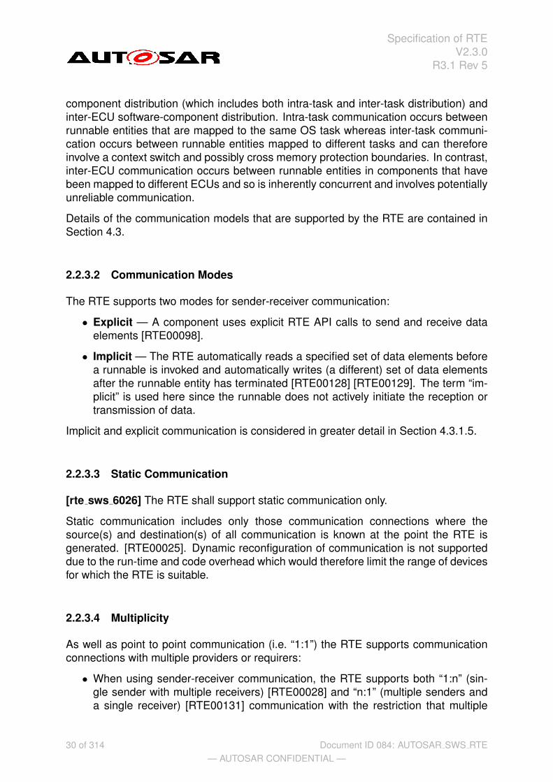
2.2.3 Communication
The communication interface of an AUTOSAR software-component consists of severalports (which are characterized by port-interfaces). An AUTOSAR software-componentcan communicate through its interfaces with other AUTOSAR software-components(whether that component is located on the same ECU or on a different ECU) or withbasic software modules that have a port and are located on the same ECU. This com-munication can only occur via the component’s ports. A port can be categorized byeither a sender-receiver or client-server port-interface. A sender-receiver interface pro-vides a message passing facility whereas a client-server interface provides functioninvocation.
2.2.3.1 Communication Models
The AUTOSAR VFB Specification [13] defines two communication models within theRTE core services; sender-receiver (signal passing) and client-server (function in-vocation). Each communication model can be applied to either intra-ECU software-
29 of 314— AUTOSAR CONFIDENTIAL —
Document ID 084: AUTOSAR SWS RTE
Specification of RTEV2.3.0
R3.1 Rev 5
component distribution (which includes both intra-task and inter-task distribution) andinter-ECU software-component distribution. Intra-task communication occurs betweenrunnable entities that are mapped to the same OS task whereas inter-task communi-cation occurs between runnable entities mapped to different tasks and can thereforeinvolve a context switch and possibly cross memory protection boundaries. In contrast,inter-ECU communication occurs between runnable entities in components that havebeen mapped to different ECUs and so is inherently concurrent and involves potentiallyunreliable communication.
Details of the communication models that are supported by the RTE are contained inSection 4.3.
2.2.3.2 Communication Modes
The RTE supports two modes for sender-receiver communication:
• Explicit — A component uses explicit RTE API calls to send and receive dataelements [RTE00098].
• Implicit — The RTE automatically reads a specified set of data elements beforea runnable is invoked and automatically writes (a different) set of data elementsafter the runnable entity has terminated [RTE00128] [RTE00129]. The term “im-plicit” is used here since the runnable does not actively initiate the reception ortransmission of data.
Implicit and explicit communication is considered in greater detail in Section 4.3.1.5.
2.2.3.3 Static Communication
[rte sws 6026] The RTE shall support static communication only.
Static communication includes only those communication connections where thesource(s) and destination(s) of all communication is known at the point the RTE isgenerated. [RTE00025]. Dynamic reconfiguration of communication is not supporteddue to the run-time and code overhead which would therefore limit the range of devicesfor which the RTE is suitable.
2.2.3.4 Multiplicity
As well as point to point communication (i.e. “1:1”) the RTE supports communicationconnections with multiple providers or requirers:
• When using sender-receiver communication, the RTE supports both “1:n” (sin-gle sender with multiple receivers) [RTE00028] and “n:1” (multiple senders anda single receiver) [RTE00131] communication with the restriction that multiple
30 of 314— AUTOSAR CONFIDENTIAL —
Document ID 084: AUTOSAR SWS RTE

Specification of RTEV2.3.0
R3.1 Rev 5
senders are not allowed for mode switch notifications, see metamodelrestrictions rte sws 2670.
The execution of the multiple senders or receivers is not coordinated by the RTE.This means that the actions of different software-components are independent –the RTE does not ensure that different senders transmit data simultaneously anddoes not ensure that all receivers read data or receive events simultaneously.
• When using client-server communication, the RTE supports “n:1” (multiple clientsand a single server) [RTE00029] communication. The RTE does not support “1:n”(single client with multiple servers) client-server communication.
Irrespective of whether “1:1”, “n:1” or “1:n” communication is used, the RTE is respon-sible for implementing the communication connections and therefore the AUTOSARsoftware-component is unaware of the configuration. This permits an AUTOSARsoftware-component to be redeployed in a different configuration without modification.
2.2.4 Concurrency
AUTOSAR software-components have no direct access to the OS and hence there areno “tasks” in an AUTOSAR application. Instead, concurrent activity within AUTOSARis based around runnable entities within components that are invoked by the RTE.
The AUTOSAR VFB specification [13] defines a runnable entity as a “sequence ofinstructions that can be started by the Run-Time Environment”. A component providesone2 or more runnable entities [RTE00031] and each runnable entity has exactly oneentry point. An entry point defines the symbol within the software-component’s codethat provides the implementation of a runnable entity.
The RTE is responsible for invoking runnable entities – AUTOSAR software-components are not able to (dynamically) create private threads of control. Hence,all activity within an AUTOSAR application is initiated by the triggering of runnable en-tities by the RTE as a result of RTEEvents.
An RTEEvent encompasses all possible situations that can trigger execution of a runn-able entity by the RTE. The different classes of RTEEvent are defined in Section 5.7.5.
The RTE supports runnable entities in any component that has an AUTOSAR interface- this includes AUTOSAR software-components and basic software modules.3
Runnable entities are divided into multiple categories with each catgory supporting dif-ferent facilities. The categories supported by the RTE are described in Section 4.2.2.2.
2The VFB specification does not permit zero runnable entities.3The OS and COM are basic software modules but present a standardized interface to the RTE and
have no AUTOSAR interface. The OS and COM therefore do not have runnable entities.
31 of 314— AUTOSAR CONFIDENTIAL —
Document ID 084: AUTOSAR SWS RTE

Specification of RTEV2.3.0
R3.1 Rev 5
2.3 The RTE Generator
The RTE generator is one of a set of tools4 that create the realization of the AUTOSARvirtual function bus for an ECU based on information in the ECU Configuration De-scription. The RTE Generator is responsible for creating the AUTOSAR software-component API functions that link AUTOSAR software-components to the OS andmanage communication between AUTOSAR software-components and between AU-TOSAR software-components and basic software modules.
The RTE generation process consists of two distinct phases:
• RTE Contract phase – a limited set of information about a component, principallythe AUTOSAR interface definitions, is used to create an application header filefor a component type. The application header file defines the “contract” betweencomponent and RTE.
• RTE Generation phase - all relevant information about components, their de-ployment to ECUs and communication connections is used to generate the RTE.One RTE is generated for each ECU in the system.
The two-phase development model ensures that the RTE generated application headerfiles are available for use for source-code AUTOSAR software-components as wellas object-code AUTOSAR software-components with both types of component havingaccess to all definitions created as part of the RTE generation process.
The RTE generation process, and the necessary inputs in each phase, are consideredin more detail in Section 3.
2.4 Design Decisions
This section details decisions that affect both the general direction that has been takenas well as the actual content of this document.
1. The role of this document is to specify RTE behavior, not RTE implementation.Implementation details should not be considered to be part of the RTE softwarespecification unless they are explicitly marked as RTE requirements.
2. An AUTOSAR system consists of multiple ECUs each of which contains an RTEthat may have been generated by different RTE generators. Consequently, thespecification of how RTEs from multiple vendors interoperate is considered to bewithin the scope of this document.
3. The RTE does not have sufficient information to be able to derive a mapping fromrunnable entity to OS task. The decision was therefore taken to require that themapping be specified as part of the RTE input.
4The RTE generator works in conjuction with other tools, for example, the OS and COM generators,to fully realize the AUTOSAR VFB.
32 of 314— AUTOSAR CONFIDENTIAL —
Document ID 084: AUTOSAR SWS RTE

Specification of RTEV2.3.0
R3.1 Rev 5
4. Support for C++ is provided by making the C RTE API available for C++ com-ponents rather than specifying a completely separate object-oriented API. Thisdecision was taken for two reasons; firstly the same interface for the C and C++
simplifies the learning curve and secondly a single interface greatly simplifiesboth the specification and any subsequent implementations.
5. There is no support within the specification for Java.
6. The support for AUTOSAR OS protection mechanisms has been deferred until alater release of the RTE software specification.
7. The AUTOSAR meta-model is a highly expressive language for defining sys-tems however for reasons of practicality certain restrictions and constraints havebeen placed on the use of the meta-model. The restrictions are described inAppendix A.
33 of 314— AUTOSAR CONFIDENTIAL —
Document ID 084: AUTOSAR SWS RTE

Specification of RTEV2.3.0
R3.1 Rev 5
3 RTE Generation Process
This chapter describes the methodology of the RTE generation. For a detailed descrip-tion of the overall AUTOSAR methodology refer to methodology document [2].
[rte sws 2514] The RTE generator shall produce the same RTE API and RTE codewhen the input information is the same.
The RTE-Generator gets involved in the AUTOSAR Methodology twice. In the followingsection the two applications of the RTE-Generator are described.
In Figure 3.1 the overall AUTOSAR Methodology is outlined with respect to the RTE.
RTE Generation Phase
RTE Contract Phase
.h.h
Component API
Generate Component API
.XML.XML
Component Internal
Behav ior Description
[API Generation]
:InternalBehav ior
.XML.XML
Component Type
Description :
AtomicSoftwareComponentType
Configure System
.XML.XML
Collection of
Av ailable SWC
Implementations
.XML.XML
System Configuration Description
:System
Extract ECU-Specific
Information
Configure ECU
.XML.XML
ECU Extract of System
Configuration :System
.XML.XML
ECU Configuration
Description
.c.c
RTE Code
.h.h
RTE Header
Generate RTE
AUTOSAR RTE
Generator
AUTOSAR Component
API Generator
AUTOSAR System
Configuration Generator
Edit ECU Configuration
AUTOSAR ECU
Configuration Editors
Figure 3.1: System Build Methodology
For the development of AUTOSAR Software Components it is essential that the ’Com-ponent API Generator Tool’ 1 produces the ’Component API’ file in the so called ’RTEContract Phase’ (see section 3.1).
The whole vehicle functionality is described with means of Composite SW-Componentsand Atomic SW-Components. In the Composite SW-Component descriptions the con-nections between the SW-Component’s ports are also defined. Such a collection ofSW-Components connected to each other, without the mapping on actual ECUs, iscalled the VFB view.
1The ’Component API Generator Tool’ might be a separate tool or the RTE-Generator might beoperated in a special mode to achieve the same functionality. This specification does not require howthe tool is implemented.
34 of 314— AUTOSAR CONFIDENTIAL —
Document ID 084: AUTOSAR SWS RTE

Specification of RTEV2.3.0
R3.1 Rev 5
During the ’Configure System’ step the ’System Configuration Generator’ gets the in-formation about the needed SW-Components, the available ECUs and the SystemConstraints. Now the Atomic SW-Components are mapped on the available ECUs.
Since in the VFB view the communication relationships between the Atomic SW-Com-ponents have been described and the mapping of each Atomic SW-Component to aspecific ECU has been fixed, the communication matrix can be generated. In the SW-Component descriptions the signals that are exchanged through ports are defined inan abstract way. Now the ’System Configuration Generator’ needs to define systemsignals (including the actual signal length and the frames in which they will be transmit-ted) to be able to transmit the application signals over some network. COM signals thatcorrespond to the system signals will be later used by the ’RTE Generator’ to actuallytransmit the application signals.
In the next step the ’System Configuration Description’ is split into descriptions for eachindividual ECU. The extract only contains information necessary to configure each ECUindividually and it is fed into the ECU Configuration for each ECU.
[rte sws 5000] The RTE is configured and generated for each ECU instance individu-ally.
The ’ECU Configuration Editors’ (see also Section 3.2) are working iteratively on the’ECU Configuration Description’ until all configuration issues are resolved. There willbe the need for several configuration editors, each specialized on a specific part ofECU Configuration. So one editor might be configuring the COM stack (not the com-munication matrix but the interaction of the individual modules) while another editor isused to configure the RTE.
Since the configuration of a specific Basic-SW module is not entirely independent fromother modules there is the need to apply the editors several times to the ’ECU Config-uration Description’ to ensure all configuration parameters are consistent.
Only when the configuration issues are resolved the ’RTE Generator’ will be used togenerate the actual RTE code (see also Section 3.3) which will then be compiled andlinked together with the other Basic-SW modules and the SW-Components code.
The ’RTE Generator’ needs to cope with many sources of information since the nec-essary information for the RTE Generator is based on the ’ECU Configuration Descrip-tion’ which might be distributed over several files and itself references to multiple otherAUTOSAR descriptions.
[rte sws 5001] The RTE Generation tools needs to support input according to theInteroperability of AUTOSAR Authoring Tools document [9].
This is just a rough sketch of the main steps necessary to build an ECU with AUTOSARand how the RTE is involved in this methodology. For a more detailed description ofthe AUTOSAR Methodology please refer to the methodology document [2]. In the nextsections the steps with RTE interaction are explained in more detail.
35 of 314— AUTOSAR CONFIDENTIAL —
Document ID 084: AUTOSAR SWS RTE

Specification of RTEV2.3.0
R3.1 Rev 5
3.1 RTE Contract Phase
To be able to support the SW-Component development with RTE-specific APIs the’Component API’ (application header file) is generated from the ’SW-Component Inter-nal Behavior Description’ (see Figure 3.1) by the RTE-Generator in the so called ’RTEContract Phase’ (see Figure 3.2).
In the SW-Component Interface description – which is using the AUTOSAR Soft-ware Component Template – at least the AUTOSAR interfaces of the particular SW-Component have to be described. This means the SW-Component Types with Portsand their Interfaces. In the SW-Component Internal Behavior description additionallythe Runnable Entities and the RTE Events are defined. From this information the RTE-Generator can generate specific APIs to access the Ports and send and receive data.
.h.h
Component API
Generate Component
API
.XML.XML
Component Internal
Behav ior Description
[API Generation]
:InternalBehav ior
.XML.XML
Component Type
Description :
AtomicSoftwareComponentType
Implement Component
.c.c
Component Implementation
Compile Component
.obj.obj
Compiled Component
Measure Resources
.XML.XML
Component Implementation
Description [resource needs] :
Implementation
.XML.XML
Component Implementation
Description [for Object-
Code] :Implementation
AUTOSAR Component
API Generator
Figure 3.2: RTE Contract Phase
With the generated ’Component API’ (application header file) the Software Compo-nent developer can provide the Software Component’s source code without being con-cerned as to whether the communication will later be local or using some network(s).
It has to be considered that the SW-Component development process is iterative andthat the SW-Component description might be changed during the development of theSW-Component. This requires the application header file to be regenerated to reflectthe changes done in the SW-Component description.
When the SW-Component has been compiled successfully the ’Component Implemen-tation Description Generation’ tool will analyze the resulting object files and enhancethe SW-Component description with the information from the specific implementation.This includes information about the actual memory needs for ROM as well as for
36 of 314— AUTOSAR CONFIDENTIAL —
Document ID 084: AUTOSAR SWS RTE

Specification of RTEV2.3.0
R3.1 Rev 5
RAM and goes into the ’Component Implementation Description’ section of the SW-Component Description template.
So when a SW-Component is delivered it will consist of the following parts:
• Component Type Description
• Component Internal Behavior Description
• The actual source and/or object code
• Component Implementation Description
The afore listed information will be needed to provide enough information for the Sys-tem Generation steps when the whole system is assembled.
3.2 RTE Configuration Editing
During the configuration of an ECU the RTE also needs to be configured. This ismainly divided into two sections: The configuration of the RTE and the request forconfiguration of other modules.
So first the ’RTE Configuration Editor’ needs to collect all the information needed to es-tablish an operational RTE. This gathering includes information on the SW-Componentinstances and their communication relationships, the Runnable Entities and the in-volved RTE-Events and so on. The main source for all this information is the ’ECUConfiguration Description’, which might provide references to further descriptions likethe SW-Component description or the System Configuration description.
One extremely important point is the mapping of application signals from SW-Compo-nent’s ports to COM signals. A mapping of the application signals to system signalshas already been defined by the ’System Configuration Generator’ (see Figure 3.1).The ’RTE Configuration Editor’ now has to substantiate this system-level mapping bymapping the application signals to COM signals for the ECU. This application signal toCOM signal mapping has to respect the mapping from application signals to systemsignals done at system generation time.
Additional requirements on the interaction between RTE and OS are specified in sec-tion 3.4.
The usage of ’ECU Configuration Editors’ covering different parts of the ’ECU Config-uration Description’ will – if there are no cyclic dependencies which do not converge– converges to a stable configuration and then the ECU Configuration process is fin-ished. A detailed description of the ECU Configuration can be found in [7]. The nextphase is the generation of the actual RTE.
37 of 314— AUTOSAR CONFIDENTIAL —
Document ID 084: AUTOSAR SWS RTE

Specification of RTEV2.3.0
R3.1 Rev 5
3.3 RTE Generation Phase
After the ECU has been entirely configured the generation of the actual RTE can beperformed. Since all the relationships to and from the other Basic-SW modules havebeen already resolved during the ECU Configuration phase, the generation can beperformed in parallel for all modules (see Figure 3.3).
.obj.obj
Compiled RTE
.c.c
RTE Code
Compile RTE
.h.h
RTE Header
AUTOSAR RTE
Generator
Generate RTE
.XML.XML
ECU Configuration
Description
Figure 3.3: RTE Generation Phase
The actual SW-Component and Basic-SW modules code will be linked together withthe RTE code to build the entire ECU software.
3.4 RTE Configuration and OS Interaction
The generated RTE interacts with AUTOSAR COM and OS. For the latter, the RTEboth uses OS objects already in existance (e.g. tasks for which the RTE generatorbuilds bodies) as well as requires new objects (e.g. a schedule table or periodic alarmsfor periodic runnable entities). The coordination of configuration information betweenthe OS and RTE is therefore key since both the RTE and OS have to agree upon theset of OS objects.
The AUTOSAR OS is configured in the ECU Configuration Description2 [7]. The RTEconfigurator/generator needs to communicate its needs to the OS and therefore itseems sensible to use the same format order to allow the communication of the setof OS object required by the generated RTE.
The specification of the OS objects used by the generated RTE, henceforth termedOsNeeds, can be done either at configuration time only or at a mixture of configurationand generation time, depending on which approach is supported by the configurationand generation tools of RTE and OS. Thus according to figure 3.4 the output informa-tion OsNeeds can be alternatively provided by the RTE Configuration Editor or the RTEGenerator.
[rte sws 5071] If the RTE Generator (in the generation phase) does not exportOsNeeds information then the RTE Configuration editor shall export the OsNeeds in-formation.
2This is the same format which is also used to store the configuration values for the RTE and the OS.
38 of 314— AUTOSAR CONFIDENTIAL —
Document ID 084: AUTOSAR SWS RTE

Specification of RTEV2.3.0
R3.1 Rev 5
.obj.obj
Compiled RTE
.c.c
RTE Code
Compile RTE
.h.h
RTE Header
AUTOSAR RTE
Generator
Generate RTE
.XML.XML
ECU Configuration
Description
Edit ECU Configuration
AUTOSAR ECU
Configuration Editors
.XML.XML
OsNeeds Configure OS
«alternative» «alternative»
Figure 3.4: RTE Editing Phase and OS interaction
[rte sws 5076] When provided with OsNeeds information, the RTE Generator (in thegeneration phase) shall utilize only the OS objects defined in the container.
Requirement 5076 indicates that it is not possible to use/introduce new OS objectswhich are not part of the OsNeeds definition when such objects are provided.
[rte sws 5077] The RTE shall access OsNeeds information from the module configu-ration container Rte_OsNeeds.
Requirement 5077 names the container that holds the OsNeeds information; andhence the container that the RTE generator should read and write. This container isseparate from the OS information that is purely read by the RTE configurator/generator(e.g. tasks) and the two containers will require merging within the OS generation pro-cess.
If the RTE Configuration editor provides a list of the OS Objects to be used the RTEGenerator then that information does not need to be recreated by the RTE generatorduring generation phase and hence the generation phase should respect the objectsprovided by the OsNeeds information.
[rte sws 5072] If no Rte_OsNeeds container is provided, the RTE Generator (in thegeneration phase) shall assume the existence of required OS objects ex nihilo andexport OsNeeds information containing all required OS objects.
If RTE Configuration editor is not able to provide the OsNeeds information (for example,because a Generic ECU Configuration Editor is used that does not know the details ofa particular RTE implementation) the RTE Generator in the generation phase shallprovide this information.
[rte sws 5073] The exported OsNeeds shall be described using the OS Configurationformat defined in the OS SWS [11] and formalized according to the ECU ConfigurationSpecification [7].
39 of 314— AUTOSAR CONFIDENTIAL —
Document ID 084: AUTOSAR SWS RTE

Specification of RTEV2.3.0
R3.1 Rev 5
The exported OsNeeds information is, by definition, the sole mechanism for the RTE toimpose existence requirements on the OS configuration process. The exported infor-mation should contain all information necessary for the OS configuration to proceed.
Since the OS Configuration format is used to describe the OsNeeds this informationcan be directly used within the OS Configuration process to enhance the information.
Caution has to be taken in order not to break the references between the RTE Config-uration and the OsNeeds . If changes on the OsNeeds are performed, for example atask priority changed, and this requires changes on the RTE configuration/generationthis has to be synchronized.
[rte sws 5074] The exported OsNeeds shall only utilize the standardized configurationparameters from the OS SWS [11] in an ICC3 delivery.
Because only the standardized configuration parameters are used the RTE and OSare independent and can be provided by different vendors. If both RTE and OS areprovided by the same vendor and they are delivered in an ISS2 cluster (bundle) re-quirement rte sws 5074 is not valid.
40 of 314— AUTOSAR CONFIDENTIAL —
Document ID 084: AUTOSAR SWS RTE

Specification of RTEV2.3.0
R3.1 Rev 5
4 RTE Functional Specification
4.1 Architectural concepts
4.1.1 Scope
In this section the concept of an AUTOSAR software-component and its usage withinthe RTE is introduced.
The Software-Component Template [17] defines the kinds of SW-Components withinthe AUTOSAR context. These are shown in Figure 4.1. The abstract ComponentTypecan not be instantiated, so there can only be either a CompositionType ora specialized class ApplicationSoftwareComponentType, SensorActuatorSoftwareComponentType, ServiceComponentType, ComplexDeviceDriverComponentType or EcuAbstractionComponentType of the abstract classAtomicSoftwareComponentType.
In the following document the term AtomicSoftwareComponentType is used ascollective term for all the mentioned non-abstract derived meta-classes.
The ComponentType is defining the type of a SW-Component which is independentof any usage and can be potentially re-used several times in different scenarios. Ina composition the types are occurring in specific roles which are called ComponentPrototypes. The prototype is the utilization of a type within a certain scenario. InAUTOSAR any ComponentType can be used as a type for a prototype.
The SW-Components shown in Figure 4.1 are located above the RTE in the architec-tural Figure 4.2.
Below the RTE there are also software entities that have an AUTOSAR Interface.These are the AUTOSAR services, the ECU Abstraction and the Complex DeviceDrivers. For these software not only the AUTOSAR Interface will be described butalso information about their internal structure will be available in the Basic SoftwareModule Description.
In the next sections the different SW-Components kinds will be described in detail withrespect to their influence on the RTE.
4.1.2 RTE and AUTOSAR Software-Components
The description of a SW-Component is divided into the sections
• hierarchical structure
• ports and interfaces
• internal behavior
• implementation
41 of 314— AUTOSAR CONFIDENTIAL —
Document ID 084: AUTOSAR SWS RTE

Specification of RTEV2.3.0
R3.1 Rev 5
cd Components
ARElement
«atpType»ComponentType
AtomicSoftwareComponentType «atpType»CompositionType
Identifiable
«atpPrototype»ComponentPrototype
SensorActuatorSoftwareComponentType
«atpType»CalprmComponentType
Serv iceComponentTypeApplicationSoftwareComponentType
EcuAbstractionComponentType
ComplexDev iceDriverComponentType
+component 1..*
*«isOfType»
+type
1
Figure 4.1: AUTOSAR SW-Component classification
which will be addressed separately in the following sections.
4.1.2.1 Structure of SW-Components
In AUTOSAR the structure of an E/E-system is described using the AUTOSAR SW-Component Template and especially the mechanism of compositions. Such a TopLevel Composition assembles subsystems and connects their ports.
Of course such a composition utilizes a lot of hierarchical levels where compositionsinstantiate other composition types and so on. But at some low hierarchical level eachcomposition only consists of AtomicSoftwareComponentType instances. And thoseinstances of AtomicSoftwareComponentTypes are what the RTE is going to be workingwith.
4.1.2.2 Ports, Interfaces and Connections
Each SW-Component is providing and/or requiring ports to communicate with otherSW-Components. This is shown in Figure 4.3. The Interface determines if the port is asender/receiver or a client/server port.
When compositions are built of instances the ports can be connected either within thecomposition or made accessible to the outside of the composition. For the connections
42 of 314— AUTOSAR CONFIDENTIAL —
Document ID 084: AUTOSAR SWS RTE
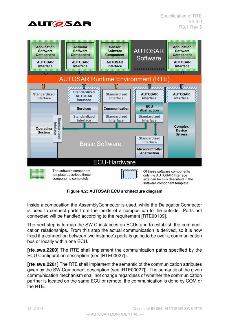
Specification of RTEV2.3.0
R3.1 Rev 5
Figure 4.2: AUTOSAR ECU architecture diagram
inside a composition the AssemblyConnector is used, while the DelegationConnectoris used to connect ports from the inside of a composition to the outside. Ports notconnected will be handled according to the requirement [RTE00139].
The next step is to map the SW-C instances on ECUs and to establish the communi-cation relationships. From this step the actual communication is derived, so it is nowfixed if a connection between two instance’s ports is going to be over a communicationbus or locally within one ECU.
[rte sws 2200] The RTE shall implement the communication paths specified by theECU Configuration description (see [RTE00027]).
[rte sws 2201] The RTE shall implement the semantic of the communication attributesgiven by the SW-Component description (see [RTE00027]). The semantic of the givencommunication mechanism shall not change regardless of whether the communicationpartner is located on the same ECU or remote, the communication is done by COM orthe RTE.
43 of 314— AUTOSAR CONFIDENTIAL —
Document ID 084: AUTOSAR SWS RTE

Specification of RTEV2.3.0
R3.1 Rev 5
Figure 4.3: SW-Components and Ports
E.g., according to rte sws 2200 and rte sws 2201 the RTE is not permitted to changethe semantic of an asynchronous client to synchronous because both client and serverare mapped to the very same ECU.
4.1.2.3 Internal Behavior
Only for AtomicSoftwareComponents the internal structure is exposed in the InternalBehavior description. Here the definition of the Runnable Entities and used RTEEventsis done (see Figure 4.4).
Runnable Entities (also abbreviated simply as Runnable) are the smallest code frag-ments that are provided by AUTOSAR software-components and those basic softwaremodules that implement AUTOSAR interfaces. They are represented by the meta-class“RunnableEntity”, see Figure 4.5.
In general, software components are composed of multiple Runnable Entities in orderto accomplish servers, receivers, feedback, etc.
[rte sws 2202] The RTE shall support multiple Runnable Entities in AUTOSAR SW-Components (see [RTE00031]).
Runnable Entities are executed in the context of an OS task, their execution is triggeredby RTEEvents. Section 4.2.2.2 gives a more detailed description of the concept ofRunnable Entities, Section 4.2.2.4 discusses the problem of mapping Runnable Entities
44 of 314— AUTOSAR CONFIDENTIAL —
Document ID 084: AUTOSAR SWS RTE

Specification of RTEV2.3.0
R3.1 Rev 5
cd InternalBehav ior Overv iew
ARElement
InternalBehav ior
ExecutableEntity
RunnableEntity
Identifiable
RTEEvent
Identifiable
ExclusiveArea
ComponentType
AtomicSoftwareComponentType
Identifiable
PerInstanceMemory
DataPrototype
InterRunnableVariablePortAPIOption
DataPrototype
CalprmElementPrototype
Identifiable
Serv iceNeeds
Implementation
SwcImplementation
+perInstanceCalprm 0..*
+canEnterExclusiveArea
0..*
+runsInsideExclusiveArea
0..*
+runnable 1..*
+behavior
+perInstanceMemory *
+interRunnableVariable 0..*
+event * +serviceNeeds 0..*
+portAPIOption 0..*
+exclusiveArea *
+sharedCalprm 0..*
*
+component 1 *
+behavior 1
Figure 4.4: SW-Component internal behavior
to OS tasks. RTEEvents and the activation of Runnable Entities by RTEEvents istreated in Section 4.2.2.3.
[rte sws 2203] The RTE shall trigger the execution of Runnable Entities in accordancewith the connected RTEEvent (see [RTE00072]).
[rte sws 2204] The RTE-Generator shall reject configurations where not all RTEEvents which can start a Runnable Entity are mapped to OS tasks (see [RTE00049]and [RTE00018]). The only exceptions are OperationInvokedEvents in case they areimplemented by a direct function call.
[rte sws 2207] The RTE shall respect the configured execution order of RunnableEntities within one OS task (see [RTE00070]).
With the information from Internal Behavior a part of the setup of the SW-Componentwithin the RTE and the OS can already be configured. Furthermore, the information(description) of the structure (ports, interfaces) and the internal behavior of an AU-TOSAR software component are sufficient for the RTE Contract Phase.
However, some detailed information is still missing and this is part of the Implementa-tion description.
45 of 314— AUTOSAR CONFIDENTIAL —
Document ID 084: AUTOSAR SWS RTE

Specification of RTEV2.3.0
R3.1 Rev 5
cd RunnableEntity
ExecutableEntity
RunnableEntity
+ canBeInvokedConcurrently: Boolean+ minimumStartInterval: Float+ symbol: String
Identifiable
DataReadAccess
Identifiable
DataSendPoint
Identifiable
DataWriteAccess
Identifiable
ServerCallPoint
+ timeout: Float
Identifiable
WaitPoint
+ timeout: Float
DataPrototype
InterRunnableVariable
+ communicationApproach: CommunicationApproachType
ARElement
InternalBehav ior
+ supportsMultipleInstantiation: Boolean
Identifiable
DataReceivePoint
ExecutableEntity
BswModuleEntity
+interRunnableVariable 0..*+runnable 1..*
+behavior
* +writtenVariable *
*
+readVariable
*
+bswEntity
0..1
+dataSendPoint
*
+runnable
+dataWriteAccess
*
+runnable
+dataReadAccess
*
+runnable
+waitPoint
*
+runnable
+dataReceivePoint
*
+runnable
+serverCallPoint
*
+runnable
Figure 4.5: SW-Component runnable entity
4.1.2.4 Implementation
In the Implementation description an actual implementation of a SW-Component isdescribed including the memory consumption (see Figure 4.6).
Note that the information from the Implementation part are only required for the RTEGeneration Phase, if at all.
46 of 314— AUTOSAR CONFIDENTIAL —
Document ID 084: AUTOSAR SWS RTE
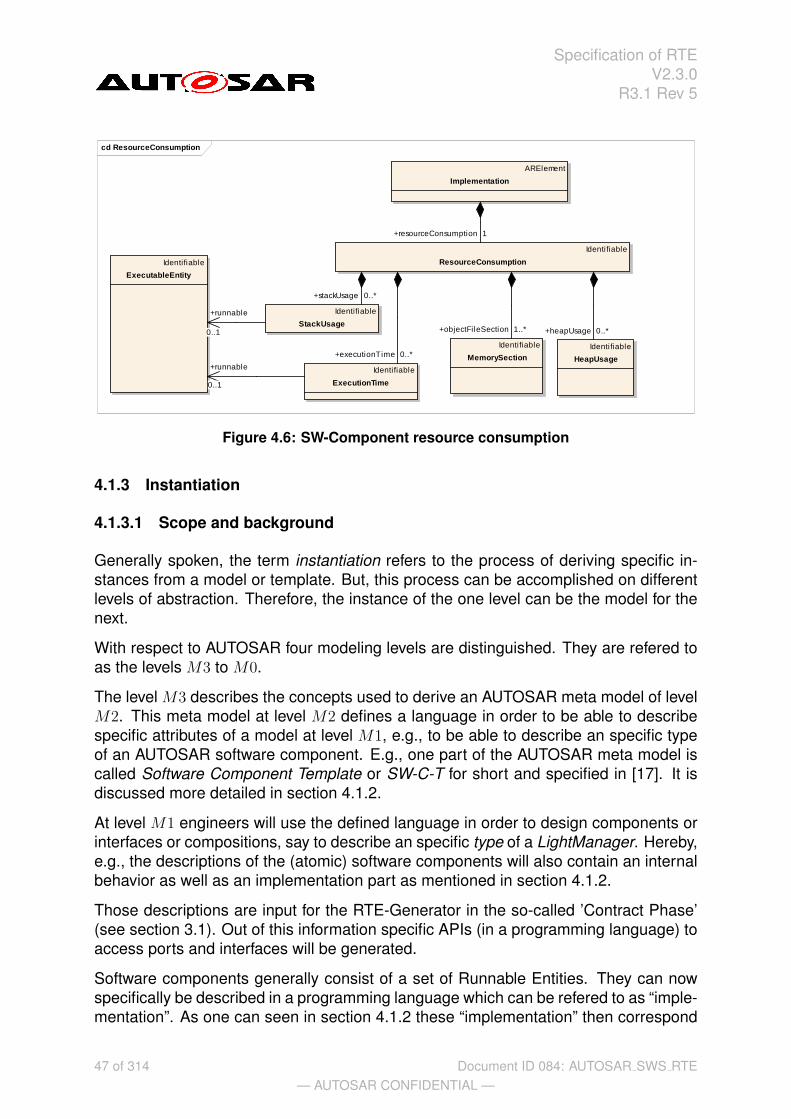
Specification of RTEV2.3.0
R3.1 Rev 5
cd ResourceConsumption
ARElement
Implementation
Identifiable
ExecutionTime
Identifiable
ResourceConsumption
Identifiable
StackUsage
Identifiable
HeapUsage
Identifiable
MemorySection
Identifiable
ExecutableEntity
+stackUsage 0..*
+objectFileSection 1..* +heapUsage 0..*
+executionTime 0..*
+resourceConsumption 1
+runnable
0..1
+runnable
0..1
Figure 4.6: SW-Component resource consumption
4.1.3 Instantiation
4.1.3.1 Scope and background
Generally spoken, the term instantiation refers to the process of deriving specific in-stances from a model or template. But, this process can be accomplished on differentlevels of abstraction. Therefore, the instance of the one level can be the model for thenext.
With respect to AUTOSAR four modeling levels are distinguished. They are refered toas the levels M3 to M0.
The level M3 describes the concepts used to derive an AUTOSAR meta model of levelM2. This meta model at level M2 defines a language in order to be able to describespecific attributes of a model at level M1, e.g., to be able to describe an specific typeof an AUTOSAR software component. E.g., one part of the AUTOSAR meta model iscalled Software Component Template or SW-C-T for short and specified in [17]. It isdiscussed more detailed in section 4.1.2.
At level M1 engineers will use the defined language in order to design components orinterfaces or compositions, say to describe an specific type of a LightManager. Hereby,e.g., the descriptions of the (atomic) software components will also contain an internalbehavior as well as an implementation part as mentioned in section 4.1.2.
Those descriptions are input for the RTE-Generator in the so-called ’Contract Phase’(see section 3.1). Out of this information specific APIs (in a programming language) toaccess ports and interfaces will be generated.
Software components generally consist of a set of Runnable Entities. They can nowspecifically be described in a programming language which can be refered to as “imple-mentation”. As one can seen in section 4.1.2 these “implementation” then correspond
47 of 314— AUTOSAR CONFIDENTIAL —
Document ID 084: AUTOSAR SWS RTE

Specification of RTEV2.3.0
R3.1 Rev 5
exactly to one implementation description as well as to one internal behavior descrip-tion. However, they are still blueprints on M1.
M0 refers to a specific running instance on a specific car.
Objects derived from those specified component types can only be executed in a spe-cific run time environment (on a specific target). The objects embody the real andrunning implementation and shall therefore be referred to as software component in-stances (on modeling level M0). E.g., there could be two component instances derivedfrom the same component type LightManager on a specific light controller ECU eachresponsible for different lights. Making instances would mean here in first place, thatit should be possible to distinguish them even though the objects are descended fromthe same model.
With respect to this more narrative description the RTE as the run time environmentshall enable the process of instantiation. Thereby the term instantiation throughout thedocument shall refer to the process of deriving M0 from M1. Therefore, this section willaddress the problems which can arise out of the instantiation process and will specifythe needs for AUTOSAR components and the AUTOSAR RTE respectively.
[rte sws 2000] The RTE-Generator shall be able to instantiate AUTOSAR softwarecomponents out of an AUTOSAR software component description.
4.1.3.2 Concepts of instantiation
Regardless of the fact that the (aforementioned) instantiation of AUTOSAR softwarecomponents can be generally achieved on a per-system basis, the RTE-Generatorrestricts its view to a per-ECU customization (see rte sws 5000).
Generally, there are two different kinds of instantiations possible:
• single instantiation – which refers to the case where only one object or AUTOSARsoftware component instance will be derived out of the AUTOSAR software com-ponent description
• multiple instantiation – which refers to the case where multiple objects or AU-TOSAR software component instances will be derived out of the AUTOSAR soft-ware component description
[rte sws 2001] The RTE shall be able to instantiate one or more AUTOSAR softwarecomponent instances out of a single AUTOSAR software component description.
[rte sws 2008] The RTE-Generator shall evaluate the attribute supportsMultipleIn-stantiation of the InternalBehavior of an AUTOSAR software component description.
[rte sws 2009] The RTE-Generator shall reject configurations where multiple instan-tiation is required, but the value of the attribute supportsMultipleInstantiation of theInternalBehavior of an AUTOSAR software component description is set to FALSE.
48 of 314— AUTOSAR CONFIDENTIAL —
Document ID 084: AUTOSAR SWS RTE

Specification of RTEV2.3.0
R3.1 Rev 5
4.1.3.3 Single instantiation
Single instantiation refers to the easiest case of instantiation.
To be instantiated merely means that the code and the corresponding data of a partic-ular RunnableEntity are embedded in a runtime context. In general, this is achieved bythe context of an OS task (see example 4.1).
Example 4.1
Runnable entity R1 called out of a task context:
1 TASK(Task1){2 ...3 R1();4 ...5 }
Since the single instance of the software component is unambigous per se no addi-tional concepts have to be added.
4.1.3.4 Multiple instantiation
[rte sws 2002] Multiple objects instantiated from a single AUTOSAR software compo-nent (type) shall be identifiable without ambiguity.
There are two principle ways to achieve this goal –
• by code duplication (of runnable entities)
• by code sharing (of reentrant runnable entities)
For now it was decided to solely concentrate on code sharing and not to support codeduplication.
[rte sws 2017] Multiple instantiation shall be achieved by sharing code.
Multiple instances can share the same code, if the code is reentrant.
4.1.3.4.1 Reentrant code
In general, side effects can appear if the same code entity is invoked by differentthreads of execution running, namely tasks. This holds particularly true, if the invokedcode entity inherits a state or memory by the means of static variables which are vis-ible to all instances. That would mean that all instances are coupled by those staticvariables.
Thus, they affect each other. This would lead to data consistency problems on onehand. On the other – and that is even more important – it would introduce a new
49 of 314— AUTOSAR CONFIDENTIAL —
Document ID 084: AUTOSAR SWS RTE

Specification of RTEV2.3.0
R3.1 Rev 5
communication mechanism to AUTOSAR and this is forbidden. AUTOSAR softwarecomponents can only communicate via ports.
To be complete, it shall be noted that a calling code entity also inherits the reentrancyproblems of its callee. This holds especially true in case of recursive calls.
4.1.3.4.2 Unambiguous object identification
[rte sws 2015] The instantiated AUTOSAR software component objects shall be un-ambiguously identifiable by an instance handle, if multiple instantiation by sharing codeis required.
4.1.3.4.3 Multiple instantiation and Per-instance memory
An AUTOSAR SW-C can define internal memory only accessible by a SW-C instanceitself. This concept is called PerInstanceMemory. The memory can only be accessedby the runnable entities of this particular instance. That means in turn, other instancesdon’t have the possibility to access this memory.
PerInstanceMemory API principles are explained in Section 5.2.5.
The API for PerInstanceMemory is specified in Section 5.6.12.
4.1.4 RTE and AUTOSAR Services
According to the AUTOSAR glossary [1] “an AUTOSAR service is a logical entity of theBasic Software offering general functionality to be used by various AUTOSAR softwarecomponents. The functionality is accessed via standardized AUTOSAR interfaces”.
Therefore, AUTOSAR services provide standardized AUTOSAR Interfaces: ports typedby standardized PortInterfaces.
[rte sws 2100] The RTE shall support the connection of AUTOSAR services only toAUTOSAR software-components located on the same ECU.
The RTE supports neither connections to AUTOSAR services located on remote ECUsnor connections between AUTOSAR services rte sws 2100.
When connecting AUTOSAR service ports to ports of AUTOSAR software componentsthe RTE maps standard RTE API calls to the symbols defined in the RTE input (i.e.XML) for the AUTOSAR service runnables of the BSW. The key technique to distin-guish ECU dependent identifiers for the AUTOSAR services is called “port-definedargument values”, which is described in Section 4.3.2.4. Currently “port-defined argu-ment values” are only supported for client-server communication. It is not possible touse a pre-defined symbol for sending or receiving data.
50 of 314— AUTOSAR CONFIDENTIAL —
Document ID 084: AUTOSAR SWS RTE

Specification of RTEV2.3.0
R3.1 Rev 5
The RTE does not pass an instance handle to the C-based API of AUTOSAR servicessince the latter are single-instantiatable (see rte sws 3806).
4.1.5 RTE and ECU Abstraction
The ECU Abstraction provides an interface to physical values for AUTOSAR softwarecomponents. It abstracts the physical origin of signals (their pathes to the ECU hard-ware ports) and normalizes the signals with respect to their physical appearance (likespecific values of current or voltage).
See the AUTOSAR ECU architecture in figure 4.2. From an architectural point of viewthe ECU Abstraction is part of the Basic Software layer and offers AUTOSAR interfacesto AUTOSAR software components. The ECU Abstraction is classified as firmware andwill mostly interact with sensor and actuator software components.
Seen from the perspective of an RTE, regular AUTOSAR ports are connected. With-out any restrictions all communication paradigms specified by the AUTOSAR VirtualFunctional Bus (VFB) shall be applicable to the ports, interfaces and connections –sender-receiver just as well as client-server mechanisms.
However, ports of the ECU Abstraction shall always only be connected to ports ofspecific AUTOSAR software components: sensor or actuator software components. Inthis sense they are tightly coupled to a particular ECU Abstraction.
Furthermore, it must not be possible (by an RTE) to connect AUTOSAR ports of theECU Abstraction to AUTOSAR ports of any AUTOSAR component located on a remoteECU (see rte sws 2051 and [RTE00136]).
This means, e.g., that sensor-related signals coming from the ECU Abstraction arealways received by an AUTOSAR sensor component located on the same ECU. TheAUTOSAR sensor component will then process the received signal and deploy it toother AUTOSAR components regardless of whether they are located on the same orany remote ECU. This applies to actuator-related signals accordingly, however, theopposite way around.
[rte sws ext 2054] The RTE-Generator expects only one instance of the ECU Ab-straction.
[rte sws 2050] The RTE-Generator shall generate a communication path betweenconnected ports of AUTOSAR sensor or actuator software components and the ECUAbstraction in the exact same manner like for connected ports of AUTOSAR softwarecomponents.
[rte sws 2051] The RTE-Generator shall reject configurations which require a com-munication path from a AUTOSAR software component to an ECU Abstraction locatedon a remote ECU.
Further information about the ECU Abstraction can be found in the corresponding spec-ification document [10].
51 of 314— AUTOSAR CONFIDENTIAL —
Document ID 084: AUTOSAR SWS RTE

Specification of RTEV2.3.0
R3.1 Rev 5
4.1.6 RTE and Complex Device Driver
A Complex Device Driver has an AUTOSAR Interface, therefore the RTE can deal withthe communication on the Complex Device Drivers ports. The Complex Device Driveris allowed to have code entities that are not under control of the RTE but yet still mayuse the RTE API (e.g. ISR2, BSW main functions).
4.2 RTE Implementation Aspects
4.2.1 Scope
This section describes some specific implementation aspects of an AUTOSAR RTE. Itwill mainly address
• the mapping of logical concepts (e.g., Runnable Entities) to technical architec-tures (namely, the AUTOSAR OS)
• the decoupling of pending interrupts (in the Basic Software) and the notificationof AUTOSAR software components
• data consistency problems to be solved by the RTE
Therefore this section will also refer to aspects of the interaction of the AUTOSAR RTEand the two modules of the AUTOSAR Basic Software with standardized interfaces(see Figure 4.7):
• the module AUTOSAR Operating System [5, 11]
• the module AUTOSAR COM [3, 6]
Having a standardized interface means first that the modules do not provide or requestservices for/of the AUTOSAR software components located above the RTE. They donot have ports and therefore cannot be connected to the aforementioned AUTOSARsoftware components. AUTOSAR OS as well as AUTOSAR COM are simply invisiblefor them.
Secondly AUTOSAR OS and AUTOSAR COM are used by the RTE in order to achievethe functionality requested by the AUTOSAR software components. The AUTOSARCOM module is used by the RTE to route a signal over ECU boundaries, but thismechanisms is hidden to the sending as well as to the receiving AUTOSAR softwarecomponent. The AUTOSAR OS module is used by the RTE in order to properly sched-ule the single Runnables in the sense that the RTE-Generator generates Task-bodieswhich contain then the calls to appropriate Runnables.
In this sense the RTE shall also use the available means to convert interrupts to notifi-cations in a task context or to guarantee data consistency.
With respect to this view the RTE is thirdly not the abstraction layer for AUTOSAR OSand AUTOSAR COM! Only the RTE offers the same interface to the AUTOSAR Soft-
52 of 314— AUTOSAR CONFIDENTIAL —
Document ID 084: AUTOSAR SWS RTE

Specification of RTEV2.3.0
R3.1 Rev 5
Figure 4.7: Scope of the section on Basic Software modules
ware Components like the VFB. For a specific ECU the RTE implements in conjunctionwith the modules of the Basis Software the entire functionality of the VFB (for thatspecific ECU). Hence, AUTOSAR OS and AUTOSAR COM are specific modules of aspecific implementation of the VFB for a specific ECU. They shall be able to supportthe implementation of the VFB functionality, but the functionality of the modules areneither known by the AUTOSAR software components nor offered to them per se.
[rte sws 2250] The RTE shall only use the AUTOSAR OS and AUTOSAR COM inorder to provide the RTE functionality to the AUTOSAR components (see [RTE00020]).
[rte sws 2251] The RTE-Generator shall construct task bodies for those tasks whichcontain Runnable Entities (see [RTE00049]).
The information for the construction of task bodies has to be given by the ECU Con-figuration description. The mapping of Runnable Entities to tasks is given as an inputby the ECU Configuration description. The RTE-Generator does not decide on themapping of Runnable Entities to tasks.
[rte sws 2254] Missing input information for the RTE-Generator regarding the map-ping of Runnable Entities to tasks or the construction of tasks bodies shall be taken asan invalid configuration and shall be rejected (see [RTE00049] and [RTE00018]).
53 of 314— AUTOSAR CONFIDENTIAL —
Document ID 084: AUTOSAR SWS RTE

Specification of RTEV2.3.0
R3.1 Rev 5
4.2.2 OS
This chapter describes the interaction between the RTE and the AUTOSAR OS. Theinteraction is realized via the standardized interface of the OS - the AUTOSAR OS API.See Figure 4.7.
The OS is statically configured by the ECU-Configuration and not by the RTE genera-tor. The RTE generator is not allowed to create tasks and other OS objects, which arenecessary for the runtime environment. Also the mapping of runnable entities to tasksis not the job of the RTE generator. This mapping has to be done in a configurationstep before, in the RTE-Configuration phase. The RTE generator is responsible for thegeneration of task bodies, which contain the calls for the runnable entities. The runn-able entities themselves are OS independent and are not allowed to use OS servicecalls. The RTE has to encapsulate such calls via the standardized RTE API.
4.2.2.1 OS Objects
Tasks
• The RTE has to create the task bodies, which contain the calls of the runnableentities. Note that the term task body is used here to describe a piece of code,while the term task describes a configuration object of the OS.
• The RTE controls the task activation/resumption either directly by calling OSservices like SetEvent() or ActivateTask() or indirectly by initializing OSalarms or starting Schedule-Tables for time-based activation of runnable enti-ties. If the task terminates, the generated taskbody also contains the calls ofTerminateTask() or ChainTask().
• The RTE generator does not create tasks. The mapping of runnable entities totasks is the input to the RTE generator and is therefore part of the RTE Configu-ration.
• The RTE configurator has to allocate the necessary tasks in the OS configuration.
OS applications
• The current AUTOSAR RTE SWS specification does not support memory protec-tion.
Events
• The RTE may use OS Events for the implementation of the abstract RTEEvents.
• The RTE therefore may call the OS service functions SetEvent(),WaitEvent(), GetEvent() and ClearEvent().
• The used OS Events are part of the input information of the RTE generator.
54 of 314— AUTOSAR CONFIDENTIAL —
Document ID 084: AUTOSAR SWS RTE

Specification of RTEV2.3.0
R3.1 Rev 5
• The RTE configurator has to allocate the necessary events in the OS configura-tion.
Resources
• The RTE may use OS Resources (standard or internal) e.g. to implement dataconsistency mechanisms.
• The RTE may call the OS services GetResource() and ReleaseResource().
• The used Resources are part of the input information of the RTE generator.
• The RTE configurator has to allocate the necessary resources (all types of re-sources) in the OS configuration.
Interrupt Processing
• An alternative mechanism to get consistent data access is disabling/enabling ofinterrupts. The AUTOSAR OS provides different service functions to handle in-terrupt enabling/disabling. The RTE may use these functions and must not usecompiler/processor dependent functions for the same purpose.
Alarms
• The RTE may use Alarms for timeout monitoring of asynchronous client/servercalls. The RTE is responsible for Timeout handling.
• The RTE may setup cyclic alarms for periodic triggering of runnable entities (runn-able entity activation via RTEEvent TimingEvent)
• The used Alarms are part of the input information of the RTE generator.
• The RTE configurator has to allocate the necessary alarms in the OS configura-tion.
Schedule Tables
• The RTE may setup schedule tables for cyclic task activation (runnable entityactivation via RTEEvent TimingEvent)
• The used schedule tables are part of the input information of the RTE generator.
• The RTE configurator has to allocate the necessary schedule tables in the OSconfiguration.
Memory Protection (SCC3/SCC4)
The current AutoSAR RTE specification does not support features of the AUTOSAR OSmemory protection mechanisms. Nevertheless for future versions of the specification,the RTE is responsible to transfer the data of sender/receiver communication as wellas for client-server communication over protection boundaries (OS applications).
Common OS features
55 of 314— AUTOSAR CONFIDENTIAL —
Document ID 084: AUTOSAR SWS RTE

Specification of RTEV2.3.0
R3.1 Rev 5
Depending on the global scheduling strategy of the OS, the RTE can make decisionsabout the necessary data consistency mechanisms. E.g. in an ECU, where all tasksare non-preemptive - and as the result also the global scheduling strategy of the com-plete ECU is non-preemptive - the RTE may optimize the generated code regardingthe mechanisms for data consistency.
Hook functions
The AUTOSAR OS Specification defines hook functions as follows:
A Hook function is implemented by the user and invoked by the operating system inthe case of certain incidents. In order to react to these on system or application level,there are two kinds of hook functions.
• application-specific: Hook functions within the scope of an individual OS Appli-cation.
• system-specific: Hook functions within the scope of the complete ECU (in gen-eral provided by the integrator).
If no memory protection is used (scalability classes SCC1 and SCC2) only the system-specific hook functions are available.
The current AutoSAR RTE SWS specification does not support memory protection.Therefore, only the system-specific hooks are relevant. In the SRS the requirements toimplement the system-specific hook functions are rejected [RTE00001], [RTE00101],[RTE00102] and [RTE00105]. The reason for the rejection is the system (ECU) globalscope of those functions. The RTE is not the only user of those functions. Other BSWmodules might have requirements to use hook functions as well. This is the reasonwhy the RTE is not able to generate these functions without the necessary informationof the BSW configuration.
It is intended that the implementation of the system specific hook functions is done bythe system integrator and NOT by the RTE generator.
4.2.2.2 Runnable Entities
The following chapter describes the runnable entities, their categories and their task-mapping aspects. The prototypes of the functions implementing runnable entities aredescribed in Chapter 5.7
Runnable entities are the schedulable parts of SW-Cs. With the exception of reentrantserver runnables that are invoked via direct function calls, they have to be mapped totasks. The mapping must be described in the ECU Configuration Description. Thisconfiguration - or just the RTE relevant parts of it - is the input of the RTE generator.
All runnable entities are activated by the RTE as a result an RTEEvent. Possible ac-tivation events are described in the meta-model by using RTEEvents (see Figure 4.8.
56 of 314— AUTOSAR CONFIDENTIAL —
Document ID 084: AUTOSAR SWS RTE

Specification of RTEV2.3.0
R3.1 Rev 5
RTEEvents are described in the following chapter. If no RTEEvent is specified as Star-tOnEvent for the runnable entity, the runnable entity is never activated by the RTE.
The runnable entities are categorized as follows. Category 1Category 1 runnable entities do not have WaitPoints and have to terminate in finitetime. With respect to some constraints, category 1 runnable entities can be mapped toBasic Tasks of the AUTOSAR OS. The VFB Specification [13] distinguishes betweenCategory 1A and Category 1B runnable entities. For mapping aspects, both sub cate-gories can be handled equally and therfore the term Category 1 is used instead.
Category 2In contrast to category 1 runnable entities, runnable entities of category 2 always haveat least one WaitPoint or they invoke a server and wait for the response to return (Syn-chronousServerCallPoint). Category 2 runnable entities usually have to be mapped toExtended Tasks, because only extended tasks provide the task state WAITING. Theexistence of at least one WaitPoint or of a SynchronousServerCallPoint classifies therunnable entity as a category 2 runnable.
Category 3Runnable entities of category 3 are described in the VFB-Specification [13] in Chapter4.5.4.4 but are currently out of scope of the RTE Specification. This restriction is alsodescribed in Section A.
4.2.2.3 RTE Events
The meta model describes the following RTE events.
Figure 4.8: Different kinds of RTE-Events
57 of 314— AUTOSAR CONFIDENTIAL —
Document ID 084: AUTOSAR SWS RTE

Specification of RTEV2.3.0
R3.1 Rev 5
T TimingEventDR DataReceivedEvent (S/R Communication only)DRE DataReceiveErrorEvent (S/R Communication only)DSC DataSendCompletedEvent (S/R Communication only)OI OperationInvokedEvent (C/S Communication only)ASCR AsynchronousServerCallReturnsEvent (C/S communication only)MS ModeSwitchEvent
According to the meta model it is possible that all kinds of RTEEvents can either1.) activate a runnable entity or2.) wakeup a runnable entity at its waitpoints
The meta model makes no restrictions. As a consequence RTE API functions wouldbe necessary to set up the waitpoints for all kinds of RTEEvents.
Nevertheless in some cases it seems to make no sense to implement all possiblecombinations of the general meta model. E.g. setting up a waitpoint, which should beresolved by a cyclic TimingEvent. Therefore the RTE SWS of AUTOSAR Release 2.0makes some restrictions, which are also described in Section A.
The meta model also allows, that the same runnable entity can be triggered by severalRTEEvents. For the current approach of the RTE and restrictions see Section 4.2.5.
T DR DRE DSC OI ASCR MSActivation of runnable entity x x x x x x xWakeup of waitpoint x x x
The table shows, that activation of runnable entity is possible for all kinds ofRTEEvents. For runnable entity activation, no explicit RTE API is necessary. TheRTE itself is responsible for the activation of the runnable entity depending on the con-figuration in the SW-C Description.
If the runnable entity contains a waitpoint, it can be resolved by the assigned RTE-Event(s). Entering the waitpoint requires an explicit call of a RTE API function. TheRTE (together with the OS) has to implement the Waitpoint inside this RTE API.
The following list shows which RTE API function has to be called to set up waitpoints.
• DataReceivedEvent: Rte_Receive()
• DataSendCompletedEvent: Rte_Feedback()
• AsynchronousServerCallReturnsEvent: Rte_Result()
4.2.2.4 Mapping of runnable entities to tasks
One of the main requirements of the RTE is ”Construction of task bodies” [RTE00049].The necessary input information e.g. the mapping of runnable entities to tasks must beprovided by the ECU configuration description.
58 of 314— AUTOSAR CONFIDENTIAL —
Document ID 084: AUTOSAR SWS RTE

Specification of RTEV2.3.0
R3.1 Rev 5
The ECU configuration description (or an extract of it) is the input for the RTE-Generator(see Figure 3.3). It is also the purpose of this document to define the necessary inputinformation. Therefore the following scenarios may help to derive requirements for theECU-Configuration Template as well as for the RTE-generator itself.Note: The scenarios do not cover all possible combinations.The RTE-Configurator configures parts of the ECU-Configuration, e.g. the mapping ofrunnable entities to tasks. In this configuration process the RTE-Configurator also allo-cates those OS-objects (e.g. Tasks, Events, Alarms...) which are used in the generatedRTE. The RTE-Configurator must be the owner of these configuration items. Otherconfigurators, e.g. the OS Configurator, should not be able to change these settings.
Some figures for better understanding use the following conventions:
Figure 4.9: Element description
4.2.2.4.1 Scenario for mapping of runnable entities to tasks
The different properties of runnable entities with respect to data access and terminationhave to be taken into account when discussing possible scenarios of mapping runnableentities to tasks.
• Runnable entities using (implicit) DataReadAccess/DataWriteAccess have to ter-minate.
• Runnable entities using (implicit) DataReadAccess/DataWriteAccess are cate-gory 1 runnables (1A or 1B). Runnable entities of category 2 do not allow (implicit)DataReadAccess/DataWriteAccess.
• Runnable entities of category 1 can be mapped either to basic or extended tasks.(see next subsection).
• Runnable entities using at least one Waitpoint are of category 2.
• Runnables of category 2 that contain WaitPoints will be typically mapped to ex-tended tasks.
• Runnables of cateogry 2 that contain a SynchronousServerCallPoint generallyhave to be mapped to extended tasks.
59 of 314— AUTOSAR CONFIDENTIAL —
Document ID 084: AUTOSAR SWS RTE

Specification of RTEV2.3.0
R3.1 Rev 5
• Runnables of category 2 that contain a SynchronousServerCallPoint can bemapped to basic tasks if no timeout monitoring is required.
• Runnables of category 2 that contain a SynchronousServerCallPoint can bemapped to basic tasks if the server runnable is invoked directly and is itself ofcategory 1.
Note that the runnable to task mapping scenarios supported by a particular RTE im-plementation might be restricted.
4.2.2.4.1.1 Scenario 1
Runnable entity category 1A: ”runnable1”
• Ports: only S/R with DataReadAccess / DataWriteAccess
• RTEEvents: TimingEvent
• no sequence of runnable entities specified
• no explicit DataSendPoint
• no WaitPoint
Possible mappings of ”runnable1” to tasks:
Basic TaskIf only one of those kinds of runnable entities is mapped to a task (task containsonly one runnable entity), or if multiple runnable entities with the same cycletime aremapped to the same task, a basic task can be used. In this case, the execution orderof the runnable entities within the task is necessary. In case the runnable entities havedifferent cycletimes, the RTE has to provide the glue-code to garantee the correct callcycle of each runnable entity.
The ECU-Configuration-Template has to provide the sequence of runnable entitiesmapped to the same task, see rte sws in 0014.
Figure 4.10 shows the possible mappings of runnable entities into a basic task. If andonly if a sequence order is specified, more than one runnable entity can be mappedinto a basic task.
Extended Task
If more than one runnable entity is mapped to the same task and the special condition(same cycletime) does not fit, an extended task is used.
If an extended task is used, the entry points to the different runnable entities might bedistinguished by evaluation of different OS events. In the scenario above, the differentcycletimes may be provided by different OS alarms. The corresponding OS eventshave to be handled inside the task body. Therefore the RTE-generator needs for eachtask the number of assigned OS Events and their names.
60 of 314— AUTOSAR CONFIDENTIAL —
Document ID 084: AUTOSAR SWS RTE

Specification of RTEV2.3.0
R3.1 Rev 5
Figure 4.10: Mapping of Category 1 runnable entities to Basic Tasks
The ECU-Configuration has to provide the OS events assigned to the RTEEvents trig-gering the runnable entities that are mapped to an extended task, see rte sws in 0039.
Figure 4.11 shows the possible mapping of the multiple runnable entities of category 1into an Extended Task. Note: The Task does not terminate.
Figure 4.11: Mapping of Category 1 runnable entities to Extended Tasks
For both, basic tasks and extended tasks, the ECU-Configuration must provide thename of the task.
The ECU-Configuration has to provide the name of the task, see rte sws in 5012.
61 of 314— AUTOSAR CONFIDENTIAL —
Document ID 084: AUTOSAR SWS RTE

Specification of RTEV2.3.0
R3.1 Rev 5
The ECU-Configuration has to provide the task type (BASIC or EXTENDED), whichcan be determined from the presence or absence of OS Events associated with thattask, see rte sws in 0040.
4.2.2.4.1.2 Scenario 2
Runnable entity category 1B: ”runnable2”
• Ports: S/R with DataSendPoints.
• RTEEvents: TimingEvent
• no sequence of runnables specified
• no WaitPoint
Possible mappings of ”runnable2” to tasks:
The following figure shows the different mappings:
• One category 1B runnable
• More than one category 1B runnable mapped to the same basic task with a spec-ified sequence order
• More than one category 1B runnable mapped into an extended task
The gluecode to realize the DataReadAccess and DataWriteAccess respectively be-fore entering the runnable and after exiting is not necessary.
Figure 4.12: Mapping of Category 1 runnable entities using no DataReadAccess /DataWriteAccess
4.2.2.4.1.3 Scenario 3
Runnable entity category 1A: ”runnable3”
• Ports: S/R with DataReadAccess / DataWriteAccess
• RTEEvents: Runnable is activated by a DataReceivedEvent
62 of 314— AUTOSAR CONFIDENTIAL —
Document ID 084: AUTOSAR SWS RTE

Specification of RTEV2.3.0
R3.1 Rev 5
• no sequence of runnables specified
• no DataSendPoint
• no WaitPoint
There is no difference between Scenario 1. Only the RTEEvent that activates therunnable entity is different.
4.2.2.4.1.4 Scenario 4
Runnable entity category 2: ”runnable4”
• Ports: S/R with DataReceivePoint and WaitPoint (blocking read)
• RTEEvents: WaitPoint referencing a DataReceivedEvent
• no sequence of runnables specified
Runnable is activated by an arbitrary RTEEvent (e.g. by a TimingEvent). When therunnable entity has entered the WaitPoint and the DataReceivedEvent occurs, therunnable entity resumes execution.
The runnable has to be mapped to an extended task. Normally each category 2 runn-able has to be mapped to its own task. Nevertheless it is not forbidden to map multiplecategory 2 runnable entities to the same task, though this might be restricted by anRTE generator. Mapping multiple category 2 runnable entities to the same task canlead to big delay times if e.g. a WaitPoint is resolved by the incoming RTEEvent, butthe task is still waiting at a different WaitPoint.
Figure 4.13: Mapping of Category 2 runnable entities to Extended Tasks
4.2.2.4.1.5 Scenario 5
There are two runnable entities implementing a client (category 2) and a server forsynchronous C/S communication and the timeout attribute of the ServerCallPoint is 0.
There are two ways to invoke a server synchronously:
• Simple function call for intra-ECU C/S communication if the canBeInvokedCon-currently attribute of the server runnable is set and if the server runnable is of
63 of 314— AUTOSAR CONFIDENTIAL —
Document ID 084: AUTOSAR SWS RTE

Specification of RTEV2.3.0
R3.1 Rev 5
category 1. In that case the server runnable is executed in the same task con-text (same stack) as the client runnable that has invoked the server. The clientrunnable can be mapped to a basic task.
• The server runnable is mapped to its own task. If the canBeInvokedConcurrentlyattribute is not set, the server runnable must be mapped to a task.
If the implementation of the synchronous server invocation does not use OSevents, the client runnable can be mapped to a basic task and the task of theserver runnable must have higher priority than the task of the client runnable.Furthermore, the task to which the client runnable is mapped must be preempt-able. This has to be checked by the RTE generator. Activation of the serverrunnable can be done by ActivateTask() for a basic task or by SetEvent() for anextended task. In both cases, the task to be activated must have higher prioritythan the task of the client runnabe to enforce a task switch (necessary, becausethe server invocation is synchronous).
4.2.2.4.1.6 Scenario 6
There are two runnable entities implementing a client (category 2) and a server forsynchronous C/S communication and the timeout attribute of the ServerCallPoint isgreater than 0.
There are again two ways to invoke a server synchronously:
• Simple function call for intra-ECU C/S communication if the canBeInvokedCon-currently attribute of the server runnable is set and the server is of category 1. Inthat case the server runnable is executed in the same task context (same stack)as the client runnable that has invoked the server and no timeout monitoring isperformed (see rte sws 3768). In this case the client runnable can be mapped toa basic task.
• The server runnable is mapped to its own task. If the canBeInvokedConcurrentlyattribute is not set, the server runnable must be mapped to a task.
If the implementation of the timeout monitoring uses OS events, the task of theserver runnable must have lower priority than the task of the client runnable andthe client runnable must be mapped to an extended task. Furthermore, bothtasks must be preemptable1. This has to be checked by the RTE generator. Thenotification that a timeout occurred is then notified to the client runnable by usingan OS Event. In order for the client runnable to immediately react to the timeout,a task switch to the client taks must be possible when the timeout occurs.
1Strictly speaking, this restriction is not necessary for the task to which the client runnable is mapped.If OS events are used to implement the timeout monitoring and the notification that the server is finished,the RTE API implementation generally uses the OS service WaitEvent, which is a point of rescheduling.
64 of 314— AUTOSAR CONFIDENTIAL —
Document ID 084: AUTOSAR SWS RTE

Specification of RTEV2.3.0
R3.1 Rev 5
4.2.2.4.1.7 Scenario 7
Runnable entity category 2: ”runnable7”
• Ports: only C/S with AsynchronousServerCallPoint and WaitPoint
• RTEEvents: AsynchronousServerCallReturnsEvent (C/S communication only)
• no sequence of runnables specified
The mapping scenario for ”runnable7”, the client runnable that collects the result of theasynchronous server invocation, is similar to Scenario 4.
65 of 314— AUTOSAR CONFIDENTIAL —
Document ID 084: AUTOSAR SWS RTE

Specification of RTEV2.3.0
R3.1 Rev 5
4.2.2.5 Activation Offset for runnable
In order to allow optimizations (smooth cpu load, mapping of runnables with differentperiods in the same task to avoid data sharing, etc.), the RTE has to handle the activa-tion offset information from a task shared reference point only for time trigger runnables.The maximum period of a task can be calculated automatically as the greatest commondivisor (GCD) of all runnables period and offset.It is assumed that the runnables worstcase execution is less than the GCD. In case of the worst case execution is greaterthan the GCD, the behavior becomes undefined.
[rte sws 7000] The RTE shall respect the configured activation offset of runnable en-tities mapped within one OS task.
[rte sws ext 7001] The runnables worst case execution time shall be less than theGCD of all runnables period and offset in activation offset context for runnables.
Example 1:This example describes 3 runnables mapped in one task with an activation offset de-fined for each runnables.
Runnable Period Activation OffsetR1 100ms 20msR2 100ms 60msR3 100ms 100ms
Table 4.1: Runnables timings
The runnables R1, R2 and R3 are mapped in the task T1 at 20 ms which is the GCDof all runnables period and activation offset.
Figure 4.14: Example of activation offset for runnables
66 of 314— AUTOSAR CONFIDENTIAL —
Document ID 084: AUTOSAR SWS RTE
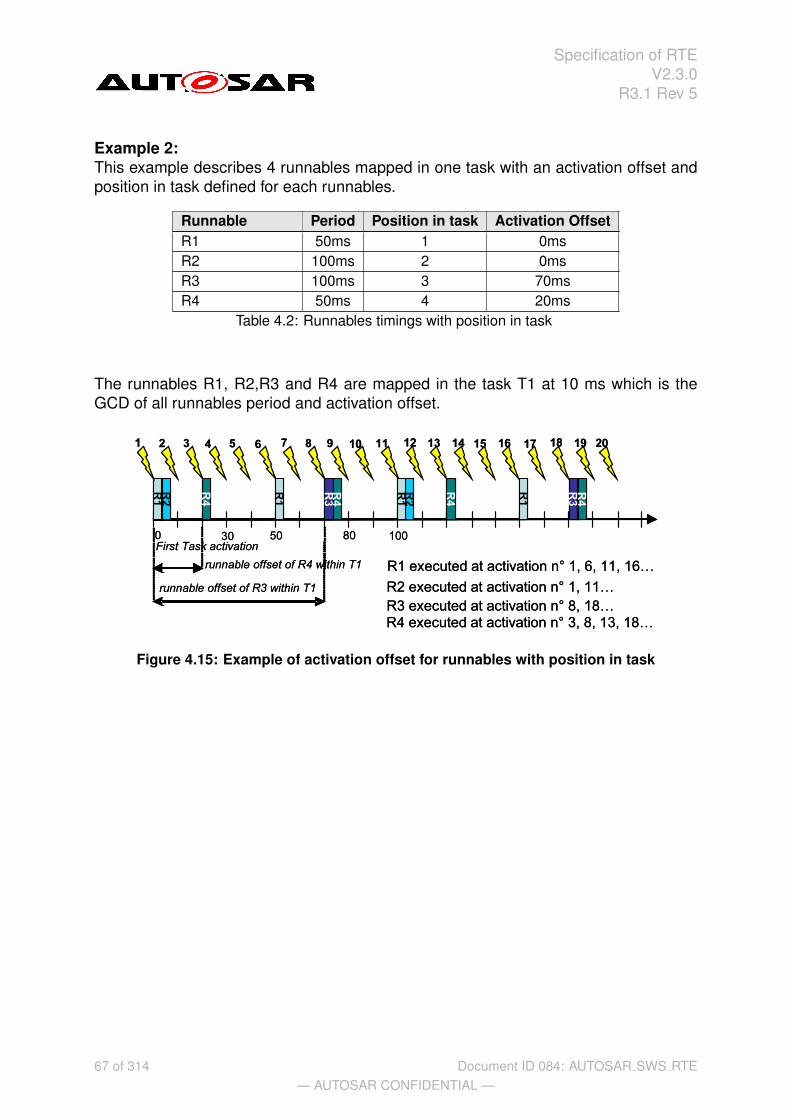
Specification of RTEV2.3.0
R3.1 Rev 5
Example 2:This example describes 4 runnables mapped in one task with an activation offset andposition in task defined for each runnables.
Runnable Period Position in task Activation OffsetR1 50ms 1 0msR2 100ms 2 0msR3 100ms 3 70msR4 50ms 4 20ms
Table 4.2: Runnables timings with position in task
The runnables R1, R2,R3 and R4 are mapped in the task T1 at 10 ms which is theGCD of all runnables period and activation offset.
Figure 4.15: Example of activation offset for runnables with position in task
67 of 314— AUTOSAR CONFIDENTIAL —
Document ID 084: AUTOSAR SWS RTE

Specification of RTEV2.3.0
R3.1 Rev 5
4.2.2.6 Activation and Start of Runnable Entities
This section defines the activation of a runnable entity by using a state machine.
The main principles for the activation of runnables are:
• runnables are activated by RTE events
• runnable activations are not queued (with exception of OperationInvokedEvent).
If a runnable is activated due to several DataReceivedEvents of DataElementswith isQueued=true, it is the responsibility of the runnabe to dequeue all queueddata.
• A ’minimum start interval’ will delay the activation of a runnable to prevent that arunnable is started more than once within the ’minimum start interval’.
Each runnable has its own state machine to describe all necessary states and transi-tions between a suspended and a running runnable. The runnable state machine isshown in Fig. 4.16.
started
suspended
debounceactivation
running
waiting
preempted activated
not activated
to be started
terminate
[runnable debounce timer >=minimum start interval]
activate
start
/runnable debounce timer =minimum start intervall
start /runnable debounce timer =0
[activated]
resume
release
preempt
wait
[activation][main]
ready
Figure 4.16: Statemachine of a runnable entity (not a server runnable) Note: the runnabledebounce timer is an increasing timer. It is local to the runnable. The runnable debouncetimer is just a concept for the specification, not for the implementation.
The state machine of a runnable is not identical to that of the task containing the runn-able, but there are dependencies between them. E.g., the runnable can only be ‘run-ning’ when the corresponding task is ‘running’.
Table 4.3 describes all runnable states in detail. The runnable state machine is splitin two sub state machines. The runnable main states describe the real state of therunnable, while the activation states describe the state of the pending activations byRTE events.
runnable state descriptionrunnable main statessuspended The runnable is not started and there is no pending request
to start the runnable.
68 of 314— AUTOSAR CONFIDENTIAL —
Document ID 084: AUTOSAR SWS RTE

Specification of RTEV2.3.0
R3.1 Rev 5
to be started The runnable is activated but not yet started. Entering the tobe started state, usually implies the activation of a task thatstarts the runnable. The runnable stays in the ‘to be started’state, when the task is already running until the gluecode ofthe task actually starts the execution of the runnable.
running The runnable code is being executed. A task that containsthe runnable is running.
waiting A task containing the runnable is waiting at a WaitPointwithin the runnable.
preempted A task containing the runnable is preempted from executingthe runnable code.
started ‘started’ is the super state of ‘running’, ‘waiting’ and ‘pre-empted’ between start and termination of the runnable.
runnable activation statesnot activated No RTE event requires the activation of the runnable.debounce activation One or more RteEvents with a startOnEvent relation to the
runnable have occurred, but the debounce timer has not yetexceeded the minimum start interval. The activation will au-tomatically advance to activated, when the debounce timerreaches the minimum start interval.
activated One or more RteEvents with a startOnEvent to the runn-able have occurred, and the debounce timer has exceededthe minimum start interval. While the activated state is ac-tive, the main state of the runnable automatically advancesfrom the suspended to the ’to be started’ state. When therunnable starts, the activation will be reset to ‘not activated’.
Table 4.3: States defined for each runnable.Note: For tasks, the equivalent state machine does not dis-tinguish between preempted and to be started. They aresubsumed as ‘ready’
[rte sws 2697] The activation of runnable entities (except for server runnables)shall behave as described by the runnable state machine in Fig. 4.16 and Table 4.3.
The following examples in Fig. 4.17 and Fig. 4.18 show the different timing situations ofthe runnables with or without a minimum start interval. The minimum start interval canreduce the number of activations by collecting more activating RTE Events within thatinterval. No activation will be lost, the activations are just delayed to keep the minimumstart interval.
When a data received event activates a runnable when it is still running, it might bethat the data is already dequeued during the current execution of the runnable. Still,the runnable will be started again. So, it is possible that a runnable that is activated bya data received event finds an empty receive queue.
A server runnable is exclusively activated by OperationInvokedEvents and imple-ments the server in client server communication. In some cases, the client server
69 of 314— AUTOSAR CONFIDENTIAL —
Document ID 084: AUTOSAR SWS RTE

Specification of RTEV2.3.0
R3.1 Rev 5
activated
started
start start start start start start start
Figure 4.17: This figure illustrates the activation of a runnable without minimum startinterval. The started state of the runnable main states and the activated state of therunnable activation states are shown. Each flash indicates the occurrence of an RTEevent. The runnable can only be activated once. The activation is not queued. Therunnable can be activated again when it is still started.
debounceactivation
started
start start start start start
activated
debounce time
debounceactivation
started
start start start start start
activated
debounce time
Figure 4.18: This figure illustrates the activation of a runnable with a minimum startinterval. The started state of the runnable main states and the debounce activation andactivated states of the runnable activation states are shown. Each flash indicates theoccurrence of an RTE event. The red arrows indicate the minimum start interval aftereach start of the runnable. An RTE event within this minimum start interval leads tothe debounce activation state. When the minimum start interval ends, the debounceactivation state changes to the activated state.
communication is implemented by RTE as a direct function call of the server by theclient. In this case, a minimum start distance is not applicable.
[rte sws 2698] RTE shall not use the minimum start interval for server runnables.
When a server runnable is called by direct function call, the states ‘to be started’,‘debounce activation’, and ‘activated’ are passed immediately. If a server runnable canbe invoked concurrently and is invoked by different clients using direct function call,each client’s concurrent execution of the server runnable has it’s own state machine.
[rte sws 2699] When RTE implements server serialization, the activations of theserver shall be queued according to Fig. 4.19.b.
70 of 314— AUTOSAR CONFIDENTIAL —
Document ID 084: AUTOSAR SWS RTE

Specification of RTEV2.3.0
R3.1 Rev 5
serialized server call
started
suspended
running
waiting
preempted activated
not activated
to be started
start
resume
release
preempt
wait[activated]
terminate
activate/activations=1
start /activations -= 1
[activations > 0]
[activations = 0]
ready
[activation][main]
for serialized server callsactivate / activations + = (activations==queue length)?0:1
b)
started
suspended
debounceactivation
running
waiting
preempted activated
not activated
to be started
terminate
[runnable debounce timer >=minimum start interval]
activate
start
/runnable debounce timer =minimum start intervall
start /runnable debounce timer =0
[activated]
resume
release
preempt
wait
[activation][main]
ready
direct server callstarted
su spended
debounceactivation
running
waiting
preempted activated
not activated
to be started
terminate
[runnable debounce timer >=minimum start interval]
activate
start
/runnable debounce timer =minimum start intervall
start /runnable debounce timer =0
[activated]
resume
release
preempt
wait
[activation][main]
ready
direct server call
for each direct function call
a)
Figure 4.19: Statemachines of a server runnable. (a) For each client where RTE im-plements the server call as a direct function call, the server runnable has a separatestate machine as displayed in the upper state charts. States that are directly passed aregrayed out. (b) The client server transactions that are queued by RTE require a queueingof the activations as displayed in the lower state chart
4.2.3 Interrupt decoupling and notifications
4.2.3.1 Basic notification principles
Several BSW modules exist which contain functionality which is not directly activated,triggered or called by AUTOSAR software-components but by other circumstances, likedigital input port level changes, complex driver actions, CAN signal reception, etc. Inmost cases interrupts are a result of those circumstances. For a definition of interrupts,see the VFB [13].
Several of these BSW functionalities create situations, signalled by an interrupt, whenAUTOSAR SW-Cs have to be involved. To inform AUTOSAR software components ofthose situations, runnables in AUTOSAR software components are activated by no-tifications. So interrupts that occur in the basic software have to be transformed intonotifications of the AUTOSAR software components. Such a transformation has to take
71 of 314— AUTOSAR CONFIDENTIAL —
Document ID 084: AUTOSAR SWS RTE

Specification of RTEV2.3.0
R3.1 Rev 5
place at RTE level at the latest! Which interrupt is connected to which notification isdecided either during system configuration/generation time or as part of the design ofComplex Device Drivers or the Microcontroller Abstraction Layer.
This means that runnables in AUTOSAR SW-Cs have to be activated or ”waiting” cat2runables in extended tasks have to be set to ”ready to run” again. In addition someevent specific data may have to be passed.
There are two different mechanisms to implement these notifications, depending onthe kind of BSW interfaces.
1. BSW with Standardized interface. Used with COM and OS.Basic-SW modules with Standardized interfaces cannot create RTEEvents. Soanother mechanism must be chosen: ”callbacks”The typical callback realization in a C/C++ environment is a function call.
2. BSW with AUTOSAR interface: Used in all the other BSW modules.Basic-SW modules with AUTOSAR-Interfaces have their interface specified in anAUTOSAR BSW description XML file which contains signal specifications accord-ing to the AUTOSAR specification. The BSW modules can employ RTE API callslike Rte Send – see 5.6.4). RTEEvents may be connected with the RTE APIcalls, so realizing AUTOSAR SW-C activation.
Note that an AUTOSAR software component can send a notification to another AU-TOSAR software component or a BSW module only via an AUTOSAR interface.
4.2.3.2 Interrupts
The AUTOSAR concept as stated in the VFB specification [13] does not allow AU-TOSAR software components to run in interrupt context. Only the Microcontroller Ab-straction Layer, Complex Device Drivers and the OS are allowed to directly interact withinterrupts and implement interrupt service routines (see Requirement BSW164). Thisensures hardware independency and determinism.
If AUTOSAR software components were allowed to run in interrupt context, one AU-TOSAR software component could block the entire system schedule for an unaccept-ably long period of time. But the main reason is that AUTOSAR software componentsare supposed to be independent of the underlying hardware so that exchangeabilitybetween ECUs can be ensured. The schedule of an ECU is more predictable and bet-ter testable if the timing effects of interrupts are restricted to the basic software of thatECU.
Furthermore, AUTOSAR software components are not allowed to explicitly block inter-rupts as a means to ensure data consistency. They have to use RTE functions for thispurpose instead, see Section 4.2.4.
72 of 314— AUTOSAR CONFIDENTIAL —
Document ID 084: AUTOSAR SWS RTE

Specification of RTEV2.3.0
R3.1 Rev 5
4.2.3.3 Decoupling interrupts on RTE level
Runnables in AUTOSAR SW-Cs may be running as a consequence of an interrupt butnot in interrupt context, which means not within an interrupt service routine! Betweenthe interrupt service routine and an AUTOSAR SW-C activation there must always bea decoupling instance. AUTOSAR SW-C runnables are only executed in the context oftasks.
The decoupling instance is latest the RTE. For the RTE there are several options torealize the decoupling of interrupts. Which option is the best depends on the configu-ration and implementation of the RTE, so only examples are given here.
Example 1:
Situation:
• An interrupt routine calls an RTE callback function
Intention:
• Start a runnable
RTE job:
• RTE starts a task containing the runnable activation code by using the ”Activate-Task()” OS service call.
• Other more sophisticated solutions are possible, e.g. if the task containing therunnable is activated periodically.
Example 2:
Situation:
• An interrupt routine calls an RTE callback function
Intention:
• Make a runnable wake up from a wait point
RTE job:
• RTE sets an OS event
These scenarios described in the examples above not only hold for RTE callback func-tions but for other RTE API functions as well.
[rte sws 3600] The RTE shall prevent runnable entities of AUTOSAR software-components to run in interrupt context.
73 of 314— AUTOSAR CONFIDENTIAL —
Document ID 084: AUTOSAR SWS RTE

Specification of RTEV2.3.0
R3.1 Rev 5
4.2.3.4 RTE and interrupt categories
Since category 1 interrupts are not under OS control the RTE has absolutely no pos-sibility to influence their execution behavior. So no category 1 interrupt is allowed toreach RTE. This is different for interrupt of category 2.
[rte sws 3594] Only interrupt category 2 can use RTE services.
4.2.3.4.1 Interrupt decoupling for COM
COM callbacks are used to inform the RTE about something that happened indepen-dently of any RTE action. This is often interrupt driven, e.g. when a data item has beenreceived from another ECU or when a S/R transmission is completed.It is the RTE’s job e.g. to create RTEEvents from the interrupt.
[rte sws 3530] The RTE has to provide callback functions to allow COM to signal COMevents to the RTE.
[rte sws 3531] The RTE has to support runnable activation by COM callbacks.
[rte sws 3532] The RTE has to support cat2 runnables to wake up from a wait pointas a result of COM callbacks.
See RTE callback API in chapter 5.9.
4.2.4 Data Consistency
4.2.4.1 General
Concurrent accesses to shared data memory can cause data inconsistencies. In gen-eral this must be taken into account when several code entities accessing the samedata memory are running in tasks with different priority levels - in other words whensystems using parallel (or quasi parallel) execution of code are designed. More gen-eral: Whenever task context-switches occur and data is shared between tasks, dataconsistency is an issue.
AUTOSAR systems use operating systems according to the AUTOSAR-OS specifica-tion which is derived from the OSEK-OS specification. The Autosar OS specificationdefines a priority based scheduling to allow event driven systems. This means thattasks with higher priority levels are able to interrupt (preempt) tasks with lower prioritylevel.
The ”lost update” example in Figure 4.20 illustrates the problem for concurrent read-modify-write accesses:
There are two tasks. Task A has higher priority than task B. A increments the com-
74 of 314— AUTOSAR CONFIDENTIAL —
Document ID 084: AUTOSAR SWS RTE

Specification of RTEV2.3.0
R3.1 Rev 5
Task B
Task A
Data X
X
1) X*=5 2) X*++ => X*=63) X = X* => X=6
Time
1) Get X‘=5 2) X‘+=23) X = X‘
1) X*=5
5 5 5 5 5 5 5 5 5 7 7 7 7 7 6 6 6 6 6 6 6 6
Figure 4.20: Data inconsistency example - lost update
monly accessed counter X by 2, B increments X by 1. So in both tasks there is a read(step1) – modify (step2) – write (step3) sequence. If there are no atomic accesses (fullycompleted read-modify-write accesses without interruption) the following can happen:
1. Assume X=5.
2. B makes read (step1) access to X and stores value 5 in an intermediate store(e.g. on stack or in a CPU register).
3. B cannot continue because it is preempted by A.
4. A does its read (step1) – modify (step2) – write (step3) sequence, which meansthat A reads the actual value of X, which is 5, increments it by 2 and writes thenew value for X, which is 7. (X=5+2)
5. A is suspended again.
6. B continues where it has been preempted: with its modify (step2) and write(step3) job. This means that it takes the value 5 form its internal store, incre-ments it by one to 6 and writes the value 6 to X (X=5+1).
7. B is supended again.
The correct result after both Tasks A and B are completed should be X=8, but theupdate of X performed by task A has been lost.
75 of 314— AUTOSAR CONFIDENTIAL —
Document ID 084: AUTOSAR SWS RTE

Specification of RTEV2.3.0
R3.1 Rev 5
4.2.4.2 Communications to look at
In AUTOSAR systems the RTE has to take care that a lot of the communication is notcorrupted by data consistency problems. RTE Generator has to apply suitable meansif required.
The following communication mechanisms can be distinguished:
• Intra ECU communication within one AUTOSAR SW-C:Communication between Runnables of one AUTOSAR SW-C running in differenttask contexts where communication between these Runnables takes place viacommonly accessed data. If the need to support data consistency by the RTEexists it must be specified by using the concepts of ”ExclusiveAreas” or ”Inter-RunnableVariables” only.
• Intra-ECU communication between AUTOSAR SW-Cs:Sender/Receiver (S/R) communication between Runnables of different AU-TOSAR SW-Cs using implicit or explicit data exchange can be realized by theRTE through commonly accessed RAM memory areas. Data consistency inClient/Server (C/S) communication can be put down to the same concepts asS/R communication. Data access collisions must be avoided. The RTE is re-sponsible for guaranteeing data consistency.
• Intra-ECU communication between AUTOSAR SW-Cs and BSW modules withAUTOSAR interfaces:Principally the same as above: Sender/Receiver (S/R) communication betweenAUTOSAR SW-Cs and BSW modules using implicit or explicit data exchange canbe realized by the RTE through shared RAM memory areas. Data consistencyin Client/Server (C/S) communication can be put down to the same concepts asS/R communication. Data access collisions must be avoided. Again, the RTEhas to guarantee data consistency!
• Inter ECU communicationCOM has to guarantee data consistency for communication between ECUs oncomplete path between the COM modules of different ECUs. The RTE on eachECU has to guarantee that no data inconsistency might occur when it invokesCOM send respectively receive calls supplying respectively receiving data itemswhich are concurrently accessed by application via RTE API call, especially whenqueueing is used since the queues are provided by the RTE and not by COM.
[rte sws 3514] The RTE has to guarantee data consistency for communication viaAUTOSAR interfaces.
4.2.4.3 Concepts
In the AUTOSAR SW-C Template [17] chapter ”Interaction between runnables withinone component”, the concepts of
76 of 314— AUTOSAR CONFIDENTIAL —
Document ID 084: AUTOSAR SWS RTE

Specification of RTEV2.3.0
R3.1 Rev 5
1. ExclusiveAreas (see section 4.2.4.5 below)
2. InterRunnableVariables (see section 4.2.4.6 below)
are introduced to allow the user (SW-Designer) to specify where the RTE shall guar-antee data consistency for AUTOSAR SW-C internal communication and executioncircumstances. This is discussed in more detail in next sections.
The AUTOSAR SW-C template specification [17] also states that AUTOSAR SW-Csmay define PerInstanceMemory, allowing reservation of static (permanent) need ofglobal RAM for the SW-C. Nothing is specified about the way Runnables might accessthis memory. RTE only provides a reference to this memory (see section 5.6) butdoesn’t guarantee data consistency for it.
The creater of an AUTOSAR SW-C has to take care by himself that accesses to RAMreserved as PerInstanceMemory out of Runnables running in different task contextsdon’t cause data inconsistencies. On the other hand this provides more freedom inusing the memory.
4.2.4.4 Mechanisms to guarantee data consistency
ExclusiveAreas and InterRunnableVariables are only mentioned in association withAUTOSAR SW-C internal communication. Nevertheless the data consistency mecha-nisms behind can be applied to communication between AUTOSAR SW-Cs or betweenAUTOSAR SW-Cs and BSW modules too. Everywhere where the RTE has to guaran-tee data consistency.
The data consistency guaranteeing mechanisms listed here are derived from AU-TOSAR SW-C Template and from further discussions. There might be more.The RTE has the responsibility to apply such mechanisms if required. The details howto apply the mechanisms are left open to the RTE supplier.
Mechanisms:
• Sequential scheduling strategyThe activation code of Runnables is sequentially placed in one task so that nointerference between them is possible because one Runnable is only activatedafter the termination of the other. Data consistency is guaranteed.
• Interrupt blocking strategyInterrupt blocking can be an appropriate means if collision avoidance is requiredfor a very short amount of time. This might be done by disabling respectivelysuspending all interrupts or - if hardware supports it - only of some interrupt levels.In general this mechanism must be applied with care because it might influenceSW in tasks with higher priority too and the timing of the complete system.
77 of 314— AUTOSAR CONFIDENTIAL —
Document ID 084: AUTOSAR SWS RTE

Specification of RTEV2.3.0
R3.1 Rev 5
• Usage of OS resourcesUsage of OS resources. Advantage in comparison to Interrupt blocking strategyis that less SW parts with higher priority are blocked. Disadvantage is that im-plementation might consume more resources (code, runtime) due to the moresophisticated mechanism.
• Task blocking strategyMutual task preemption is prohibited. This might be reached e.g. by assign-ing same priorities to affected tasks, by assigning same internal OS resource toaffected tasks or by configuring the tasks to be non-preemptive.
• Cooperative Runnable placement strategyThe principle is that tasks containing Runnables to be protected by ”CooperativeRunnable placement strategy” are not allowed to preempt other tasks also con-taining Runnables to be protected by ”Cooperative Runnable placement strategy”when one of the Runnables to protect is active - but are allowed between Runn-able executions. The RTE’s job is to create appropriate task bodies and use OSservices or other mechanisms to achieve the required behavior.
To point out the difference to ”Task blocking strategy”:In ”Task blocking strategy” no task containing Runnables with access to the Ex-clusiveArea at all is allowed to preempt another task containing Runnables withaccess to same ExclusiveArea. In ”Cooperative Runnable placement strategy”this task blocking mechanism is limited to tasks defined to be within same coop-erative context.
Example to explain the cooperative mechanism:
– Runnables R2 and R3a are marked to be protected by cooperative mecha-nism.
– Runnables R1, R3b and R4 have no cooperative marking.
– R1 is activated in Task T1, R2 is activated in Task T2, R3a is activated inTask T3a, R3b is activated in Task T3b, R4 is activated in Task T4.
– Task priorities are: T4 > T3a > T2 > T1, T3b has same priority as T3a
This setup results in this behavior:
– T4 can always preempt all other tasks (Higher prio than all others).
– T3b can preempt T2 (higher prio of T3b, no cooperative restriction)
– T3a cannot preempt T2 (Higher prio of T3a but same cooperative context).So data access of Runnable R2 to common data cannot interfere with dataaccess by Runnable R3a. Nevertheless if both tasks T3a and T2 are readyto run, it’s guaranteed that T3a is running first.
– T1 can never preempt one of the other tasks because of lowest assignedprio.
78 of 314— AUTOSAR CONFIDENTIAL —
Document ID 084: AUTOSAR SWS RTE

Specification of RTEV2.3.0
R3.1 Rev 5
• Copy strategyIdea: The RTE creates copies of data items so that concurrent accesses in dif-ferent task contexts cannot collide because some of the accesses are redirectedto the copies.
How it can work:
– Application for read conflicts:For all readers with lower priority than the writer a read copy is provided.
Example:There exist Runnable R1, Runnable R2, data item X and a copy dataitem X*. When Runnable R1 is running in higher priority task context thanR2, and R1 is the only one writing X and R2 is reading X it is possible toguarantee data consistency by making a copy of data item X to variable X*before activation of R2 and redirecting write access from X to X* or the readaccess from X to X* for R2.
– Application for write conflicts:If one or more data item receiver with a higher priority than the sender exist,a write copy for the sender is provided.
Example:There exist Runnable R1, Runnable R2, data item X and copy data item X*.When Runnable R1 (running in lower priority task context than R2) iswriting X and R2 is reading X, it is possible to guarantee data consistencyby making a copy of data item X to data item X* before activation of R1together with redirecting the write access from X to X* for R1 or the readaccess from X to X* for R2.
Usage of this copy mechanism may make sense if one or more of the followingconditions hold:
– This copy mechanism can handle those cases when only one instance doesthe data write access.
– R2 is accessing X several times.
– More than one Runnable R2 has read (resp. write) access to X.
– To save runtime is more important than to save code and RAM.
– Additional RAM requirements to hold the copies is acceptable.
Further issues to be taken into account:
– AUTOSAR SW-Cs provided as source code and AUTOSAR SW-Cs pro-vided as object code may or have to be handled in different ways. Theredirecting mechanism for source code could use macros for C and C++very efficiently whereas object-code AUTOSAR SW-Cs most likely are
79 of 314— AUTOSAR CONFIDENTIAL —
Document ID 084: AUTOSAR SWS RTE
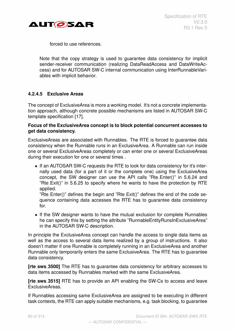
Specification of RTEV2.3.0
R3.1 Rev 5
forced to use references.
Note that the copy strategy is used to guarantee data consistency for implicitsender-receiver communication (realizing DataReadAccess and DataWriteAc-cess) and for AUTOSAR SW-C internal communication using InterRunnableVari-ables with implicit behavior.
4.2.4.5 Exclusive Areas
The concept of ExclusiveArea is more a working model. It’s not a concrete implementa-tion approach, although concrete possible mechanisms are listed in AUTOSAR SW-Ctemplate specification [17].
Focus of the ExclusiveArea concept is to block potential concurrent accesses toget data consistency.
ExclusiveAreas are associated with Runnables. The RTE is forced to guarantee dataconsistency when the Runnable runs in an ExclusiveArea. A Runnable can run insideone or several ExclusiveAreas completely or can enter one or several ExclusiveAreasduring their execution for one or several times .
• If an AUTOSAR SW-C requests the RTE to look for data consistency for it’s inter-nally used data (for a part of it or the complete one) using the ExclusiveAreaconcept, the SW designer can use the API calls ”Rte Enter()” in 5.6.24 and”Rte Exit()” in 5.6.25 to specify where he wants to have the protection by RTEapplied.”Rte Enter()” defines the begin and ”Rte Exit()” defines the end of the code se-quence containing data accesses the RTE has to guarantee data consistencyfor.
• If the SW designer wants to have the mutual exclusion for complete Runnableshe can specify this by setting the attribute ”RunnableEntityRunsInExclusiveArea”in the AUTOSAR SW-C description.
In principle the ExclusiveArea concept can handle the access to single data items aswell as the access to several data items realized by a group of instructions. It alsodoesn’t matter if one Runnable is completely running in an ExclusiveArea and anotherRunnable only temporarily enters the same ExclusiveArea. The RTE has to guaranteedata consistency.
[rte sws 3500] The RTE has to guarantee data consistency for arbitrary accesses todata items accessed by Runnables marked with the same ExclusiveArea.
[rte sws 3515] RTE has to provide an API enabling the SW-Cs to access and leaveExclusiveAreas.
If Runnables accessing same ExclusiveArea are assigned to be executing in differenttask contexts, the RTE can apply suitable mechanisms, e.g. task blocking, to guarantee
80 of 314— AUTOSAR CONFIDENTIAL —
Document ID 084: AUTOSAR SWS RTE

Specification of RTEV2.3.0
R3.1 Rev 5
data consistency for data accesses in the common ExclusiveArea. However, specialsattributes can be set that require certain data consistency mechanisms in which casethe RTE generator is forced to apply the selected mechanism.
4.2.4.5.1 Assignment of data consistency mechanisms
There might be domain, ECU or even project specific needs which data consistencymechanism makes sense most to be applied to an ExclusiveArea. The decision whichmechanism has to be applied by RTE is taken during ECU integration by setting theExclusiveArea configuration parameter ExclusiveAreaImplMechanism. This parameteris an input for RTE generator.
As stated in section 4.2.4.4 there might be more mechanisms to realize ExclusiveAr-eas as mentioned in this specification. So RTE implementations might provide othermechanisms in plus by a vendor specific solutions. This allows further optimizations.
Actually following values for configuration parameter ExclusiveAreaImplMechanismmust be supported:
• InterruptBlockingThis value requests enabling and disabling of Interrupts and is based on the In-terrupt blocking strategy.
• OSResourcesThis value requests to apply the Usage of OS recources mechanism.
• NonPreemptiveTasksThis value requests to apply the Task blocking strategy.
• CooperativeRunnablePlacementThis value requires to apply the Cooperative Runnable Placement Strategy.
The strategies / mechanisms are described in general in section 4.2.4.4.
[rte sws 3504] If the configuration parameter ExclusiveAreaImplMechanism of an Ex-clusiveArea is set to value ”InteruptBlocking” the RTE generator shall use the mech-anism of Interrupt blocking to guarantee data consistency if data inconsistency couldoccur.
[rte sws 3595] If the configuration parameter ExclusiveAreaImplMechanism of an Ex-clusiveArea is set to value ”OSResources” the RTE generator shall use OS resourcesto guarantee data consistency if data inconsistency could occur.
The requirements above have the limitation ”if data inconsistency could occur”because it makes no sense to apply a data consistency mechanism if no potentialdata inconsistency can occur. This can be relevant if e.g. the ”Sequential schedulingstrategy” (described in section 4.2.4.4) still has solved the item by the ECU integrator
81 of 314— AUTOSAR CONFIDENTIAL —
Document ID 084: AUTOSAR SWS RTE

Specification of RTEV2.3.0
R3.1 Rev 5
defining an appropriate runnable-to-task mapping.
[rte sws 3596] If the configuration parameter ExclusiveAreaImplMechanism of an Ex-clusiveArea is set to value ”NonPreemptiveTasks” the RTE generator shall generatecode relying on the fact that the task containing Runnables accessing the Exclu-siveArea cannot be preempted by other tasks containing Runnables accessing thesame ExclusiveArea too.
For usage of value ”NonPreemptiveTasks” it is assumed that the correspondingrunnable to task mapping and the task configuration has been done appropriate.
[rte sws 3503] If the configuration parameter ExclusiveAreaImplMechanism of an Ex-clusiveArea is set to value ”CooperativeRunnablePlacement” the RTE generator shallgenerate code according the Cooperative Runnable Placement Strategy to guaranteedata consistency.
Since the decision to select the Cooperative runnable placement strategy to prohibitdata access conflicts affects the behavior of several tasks and potentially many Exclu-siveAreas the RTE generator is not allowed to override the decision.
In a SWC code, it is not allowed to use waitpoints inside an ExclusiveArea: The RTEgenerator might use OSEK services to implement ExclusiveAreas and waiting for anOS event is not allowed when an OSEK resource has been taken for example. ForRunnableEntityEntersExclusiveArea, the RTE generator cannot check if waitpoints areinside an ExlusiveArea. Therefore, this is the responsibility of the SWC Code writ-ter to ensure that no waits points are used inside exclusive area. But for runnable”RunnableEntityRunsInExclusiveArea”, the RTE generator is able to do the followingcheck.
[rte sws 7005]The RTE generator shall reject a configuration with a waitpoint appliedto a runnable for which the attribute ”RunnableEntityRunsInExclusiveArea” is set.
4.2.4.6 InterRunnableVariables
A non-composite AUTOSAR SW-C can reserve InterRunnableVariables which can beaccessed by the Runnables of this one AUTOSAR SW-C (also see section 4.3.3.1).Read and write accesses are possible. There is a separate set of those variables perAUTOSAR SW-C instance.
Again the RTE has to guarantee data consistency. Appropriate means will depend onRunnable placement decisions which are taken during ECU configuration.
[rte sws 3516] The RTE has to guarantee data consistency for communication be-tween Runnables of one AUTOSAR SW-Component instance using the same Inter-RunnableVariable.
Next the two kinds of InterRunnableVariables are treated:
82 of 314— AUTOSAR CONFIDENTIAL —
Document ID 084: AUTOSAR SWS RTE
Specification of RTEV2.3.0
R3.1 Rev 5
1. InterRunnableVariables with implicit behavior
2. InterRunnableVariables with explicit behavior
4.2.4.6.1 InterRunnableVariables with implicit behavior
In applications with very high SW-C communication needs and much real time con-straints (like in powertrain domain) the usage of a copy mechanism to get data consis-tency might be a good choice because during Runnable execution no data consistencyoverhead in form of concurrent access blocking code and runtime during its executionexists - independent of the number of data item accesses.Costs are code overhead in the Runnable prolog and epilog which is often be minimalcompared to other solutions. Additional RAM need for the copies comes in plus.
When InterRunnableVariables with implicit behavior are used the RTE is required tomake the data available to the Runnable using the semantic of a copy operation but isnot necessarily required to use a unique copy for each Runnable.
Focus of InterRunnableVariable with implicit behavior is to avoid concurrent ac-cesses by redirecting second, third, .. accesses to data item copies.
[rte sws 3517] The RTE shall guarantee data consistency for InterRunnableVariableswith implicit behavior by avoiding concurrent accesses to data items specified by In-terRunnableVariables using one or more copies and redirecting accesses to the copies.
Compared with Sender/Receiver communication
• Like with DataReadAccess/DataWriteAccess the Runnable IN data is stable dur-ing Runnable execution, which means that during an Runnable execution severalread accesses to an InterRunnableVariable always deliver the same data itemvalue.
• Like with DataWriteAccess/DataWriteAccess the Runnable OUT data is for-warded to other Runnables not before Runnable execution has terminated, whichmeans that during an Runnable execution write accesses to InterRunnableVari-able are not visible to other Runnables.
This behavior requires that Runnable execution terminates.
[rte sws 3582] Several read accesses to InterRunnableVariables with implicit behav-ior during a Runnable execution shall always deliver the same data item value.
[rte sws 3583] Several write accesses to InterRunnableVariables with implicitbehavior during a Runnable execution shall result in only one update of the Inter-RunnableVariable content visible to other Runnables with the last written value.
83 of 314— AUTOSAR CONFIDENTIAL —
Document ID 084: AUTOSAR SWS RTE

Specification of RTEV2.3.0
R3.1 Rev 5
[rte sws 3584] The update of InterRunnableVariables with implicit behavior doneduring a Runnable execution shall be made available to other Runnables after theRunnable execution has terminated.
The usage of InterRunnableVariables with implicit behavior shall be valid for category1a and 1b Runnable entities. Usage in category 2 (and 3) Runnables is not allowedbecause there Runnable termination is not guaranteed and so it’s not guaranteed thatother Runnables will ever get the updated data. See also requirement rte sws 3518.
For API of InterRunnableVariables with implicit behavior see sections 5.6.20 and5.6.21.
For more details how this mechanism could work see ”Copy strategy” in section 4.2.4.4.
4.2.4.6.2 InterRunnableVariables with explicit behavior
In many applications saving RAM is more important than saving runtime. Also someapplication require to have access to the newest data item value without any delay,even several times during execution of a Runnable.
Both requirements can be fulfilled when RTE supports data consistency by blockingsecond/third/.. concurrent accesses to a signal buffer if data consistency is jeopar-dized. (Most likely RTE has nothing to do if SW is running on a 16bit machine andmaking an access to an 16bit value when a 16bit data bus is present.)
Focus of InterRunnableVariables with explicit behavior is to block potential con-current accesses to get data consistency.
The mechanism behind is the same as in the ExclusiveArea concept (see section4.2.4.5). But although ExclusiveAreas can handle single data item accesses too, theirAPI is made to make the RTE to apply data consistency means for a group of in-structions accessing several data items as well. So when using an ExclusiveArea toprotect accesses to one single common used data item each time two RTE API callsgrouped around are needed. This is very inconvenient and might lead to faults if thecalls grouped around might be forgotton.The solution is to support InterRunnableVariables with explicit behavior.
[rte sws 3519] The RTE shall guarantee data consistency for InterRunnableVariableswith explicit behavior by blocking concurrent accesses to data items specified byInterRunnableVariables.
The RTE generator is not free to select on it’s own if implicit or explicit behavior shallbe applied. Behavior must be known at AUTOSAR SW-C design time because in caseof InterRunnableVariables with implicit behavior the AUTOSAR SW-C designer mightrely on the fact that several read accesses always deliver same data item value.
84 of 314— AUTOSAR CONFIDENTIAL —
Document ID 084: AUTOSAR SWS RTE

Specification of RTEV2.3.0
R3.1 Rev 5
[rte sws 3580] The RTE shall supply different APIs for InterRunnableVariables withimplicit behavior and InterRunnableVariables with explicit behavior.
For API of InterRunnableVariables with explicit behavior see sections 5.6.22 and5.6.23.
4.2.5 Multiple trigger of Runnables
Concurrent activation
The AUTOSAR SW-C template specification [17] states that runnable entities (furthercalled ”Runnables”) might be invoked concurrently several times if the Runnables at-tribute ”canBeInvokedConcurrently” is set. It’s then in the responsability of the AU-TOSAR SW-C designer that no data might be corrupted when the Runnable is acti-vated several times in parallel.
[rte sws 3523] The RTE has to support concurrent activation of the same instanceof a runnable entity if the associative attribute ”canBeInvokedConcurrently” is set toTRUE. This includes concurrent activation in several tasks. If the attribute is not setresp. set to FALSE, concurrent activation of the runnable entity is forbidden.
Activation by several RTEEvents
Nevertheless a Runnable whose attribute ”canBeInvokedConcurrently” is NOT setmight be still activated by several RTEEvents if activation configuration guaranteesthat concurrent activation can never occur. This includes activation in different tasks. Astandard use case is the activation of same instance of a runnable in different modes.
[rte sws 3520] The RTE supports activation of same instance of a runnable entity bymultiple RTEEvents.
RTEEvents are triggering Runnable activation and may supply 0..several role param-eters, see section 5.7.3. Role parameters are not visible in the Runnables signature- except in those triggered by an OperationInvokedEvent. With the exception of theRTEEvent OperationInvokedEvent all role parameters can be accessed by user withimplicit or explicit Receiver API.
[rte sws 3524] The RTE supports activation of same instance of a runnable entity byRTEEvents of different kinds.
The RTE shall NOT support a runnable entity triggered by an RTEEvent OperationIn-vokedEvent to be triggered by any other RTEEvent except for other OperationIn-vokedEvents of compatible operations. This limitation is stated in appendix in sectionA.2.
85 of 314— AUTOSAR CONFIDENTIAL —
Document ID 084: AUTOSAR SWS RTE

Specification of RTEV2.3.0
R3.1 Rev 5
4.2.6 Measurement and Calibration
4.2.6.1 General
Calibration is the process of adjusting an ECU SW to fulfill its tasks to control physicalprocesses respectively to fit it to special project needs or environments. To do this twodifferent mechanisms are required and have to be distinguished:
1. MeasurementMeasure what’s going on in the ECU e.g. by monitoring communication data(Inter-ECU, Intra-ECU, Intra-SWC). There are several ways to get the monitordata out of the ECU onto external visualization and interpretation tools.
2. CalibrationBased on the measurement data the ECU behavior is modified by changingparameters like runtime SW switches, process controlling data of primitive orcomplex type, interpolation curves or interpolation fields. In the following for suchparameters the term calibration parameter is used.
Online and offline calibration
The way how measurement and calibration is performed is company, domain andproject specific. Nevertheless two different basic situations can be distinguished andare important for understanding:
1. Offline calibrationMeasure when ECU is running, change calibration data when ECU is off.Process might look like this:
(a) Flash the ECU with current program file
(b) PowerUp ECU in target (actual or emulated) environment
(c) Measure running ECU behavior - log or monitor via external tooling
(d) Switch off ECU
(e) Change calibration parameters and create a new flashable program file (hex-file) e.g. by performing a new SW make run
(f) Back to (a).
Do loop as long as a need for calibration parameter change exists or the Flashsurvives.
2. Online calibration
Do measurement and calibration in parallel.In this case in principle all steps mentioned in ”Offline calibration” above haveto be performed in parallel. So other mechanisms are introduced avoiding ECUflashing when modifying ECU parameters. ECU works temporarily with changed
86 of 314— AUTOSAR CONFIDENTIAL —
Document ID 084: AUTOSAR SWS RTE
Specification of RTEV2.3.0
R3.1 Rev 5
data and when the calibration process is over the result is an updated set ofcalibration data. In next step this new data set might be merged into the existingprogram file or the new data set might be an input for a new SW make run. Inboth cases the output is a new program file to flash into the ECU.
Process might look like this:
(a) Flash the ECU with current program file
(b) PowerUp ECU in target environment
(c) Measure running ECU behavior and temporarily modify calibration parame-ters. Store set of updated calibration parameters (not on the ECU but on thecalibration tool computer). Actions in step c) may be done iteratively.
(d) Switch off ECU
(e) Create a new flashable program file (hex-file) containing the new calibrationparameters
Procedure over
4.2.6.2 Measurement
4.2.6.2.1 What can be measured
The AUTOSAR SW-C template specification [17] explains to which AUTOSAR proto-types a measurement pattern can be applied.
RTE provides measurement support for
1. communication between PortsMeasurable are
• DataElementPrototypes of a SenderReceiverInterface used in a PortProto-type (of a ComponentPrototype) to capture sender-receiver communicationbetween ComponentPrototypes
• ArgumentPrototypes of an OperationPrototype in a ClientServerInterface tocapture client-server communication between ComponentPrototypes
2. communication inside of AUTOSAR SW-CsMeasurable are InterrunnableVariables
4.2.6.2.2 RTE support for Measurement
The way how measurement data is read out of the ECU is not focus of the RTE spec-ification. But the RTE structure and behavior must be specified in that way that mea-surement values can be provided by RTE during ECU program execution.
87 of 314— AUTOSAR CONFIDENTIAL —
Document ID 084: AUTOSAR SWS RTE

Specification of RTEV2.3.0
R3.1 Rev 5
To avoid synchronization effort it shall be possible to read out measurement data asyn-chronously to RTE code execution. For this the measurement data must be stable. Asa consequence this might forbid direct reuse of RAM locations for implementation ofseveral AUTOSAR communications which are independent of each other but occurringsequentially in time (e.g. usage of same RAM cell to store UInt8 data sender receivercommunication data between Runnables at positions 3 and 7 and later the same RAMcell for the communication between Runnables at positions 9 and 14 of same periodi-cally triggered task). So applying measurable elements might lead to less optimizationsin the generated RTE’s code and to increased RAM need.
There are circumstances when RTE will store same communication data in differentRAM locations, e.g. when realizing implicit sender receiver communication or Inter-RunnableVariables with implicit behavior. In these cases there is only the need to havethe content of one of these stores made accessible from outside.
The information that measurement shall be supported by RTE is defined in appliedSwDataDefProps:The value READ-ONLY of the property swCalibrationAccess defines that measure-ment shall be supported, any other value of the property swCalibrationAccess is to beignored for measurement.
Following requirements rte sws 3900, rte sws 3901 and rte sws 3902 cover 2 caseseach where SwDataDefProps can be applied:
• On level of type (only supported for primitive types):Every instance of the type is to be measured
• On level of DataPrototype and its specializations (e.g. ArgumentPrototype orInterrunnableVariable)) (supported for all types):The settings override the settings given by the type
SwDataDefProps contain more informations how measurement values are to be in-terpreted and presented by external calibration tools. These informations are neededfor the ASAM2 respectively A2L file generation. Afterwards the A2L file is used byECU-external measurement and calibration tools so that these tools know e.g. how tointerpret raw data received from ECU and how to get them.
SwDataDefProps also contain information about which section shall be used toallocate memory for measurement data. For that see section 4.2.6.3.5.7.
For sender-receiver resp. client-server communication same or compatible interfacesare used to specified connected ports. So very often measurement will be demandedtwo times for same or compatible DataElementPrototype on provide and require sideof a 1:1 communication resp. multiple times in case of 1:N or M:1 communication. Inthat case providing more than one measurement value for a DataElementPrototypedoesn’t make sense and would increase ECU resources need excessively. Insteadonly one measurement value shall be provided.
88 of 314— AUTOSAR CONFIDENTIAL —
Document ID 084: AUTOSAR SWS RTE

Specification of RTEV2.3.0
R3.1 Rev 5
Sender-receiver communication
[rte sws 3900] If the property swCalibrationAccess enclosed in the SwDataDefPropsof a DataPrototype or its associated type used in an interface of a sender-receiver portof a ComponentPrototype is set to READ-ONLY the RTE generator has to provide onereference to a location in memory where the actual content of the instance specificdata of the corresponding DataElementPrototype of the communication can be read.
To prohibit multiple measurement values for same communication:(Note that affected DataElementPrototypes might be specified in same or compatibleport interfaces.)
[rte sws 3972] For 1:1 and 1:N sender-receiver communication the RTE shall providemeasurement values taken from sender side if measurement is demanded in provideand require port.
[rte sws 3973] For N:1 intra-ECU sender-receiver communication the RTE shall pro-vide measurement values taken from receiver side if measurement is demanded inprovide and require ports.
Note:See further below for support of queued communication.
[rte sws 3974] For a DataElementPrototype with measurement demand associatedwith received data of inter-ECU sender-receiver communication the RTE shall provideonly one measurement store reference containing the actual received data even if sev-eral receiver ports demand measurement.
Client-Server communication
[rte sws 3901] If the property swCalibrationAccess enclosed in the SwDataDefPropsof an ArgumentPrototype or its associated type used in an interface of a client-serverport of a ComponentProtype is set to READ-ONLY the RTE generator has to provideone reference to a location in memory where the actual content of the instance specificargument data of the communication can be read.
To prohibit multiple measurement values for same communication:(Note that affected DataElementPrototypes might be specified in same or compatibleport interfaces.)
[rte sws 3975] For intra-ECU client-server communication the RTE shall provide mea-surement values taken from client side if measurement of an ArgumentPrototype isdemanded by provide and require ports.
[rte sws 3976] For inter-ECU client-server communication with the client beingpresent on same ECU as the RTE, the RTE shall provide measurement values takenfrom client side.
[rte sws 3977] For inter-ECU client-server communication with the server beingpresent on same ECU as the RTE, the RTE shall provide measurement values taken
89 of 314— AUTOSAR CONFIDENTIAL —
Document ID 084: AUTOSAR SWS RTE

Specification of RTEV2.3.0
R3.1 Rev 5
from server if no client present on same ECU as the server is connected with thatserver too.
Note:When a measurement is applied to a client-server call additional copy code might beproduced so that a zero overhead direct server invocation is no longer possible for thiscall.
InterrunnableVariables
[rte sws 3902] If the property swCalibrationAccess enclosed in the SwDataDefPropsof an InterRunnableVariable or its associated type is set to READ-ONLY the RTEgenerator has to provide one reference to a location in memory where the actualcontent of the InterRunnableVariable can be read for a specific instantiation of theAUTOSAR SWC.
Unconnected ports or compatible interfaces
As stated in section 5.2.7 RTE supports handling of unconnected ports.
Measurement support for unconnected sender-receiver provide ports makes sensesince a port might be intentionally added for monitoring purposes only.
Measurement support for unconnected sender-receiver require ports makes sensesince the measurement is specified on the type level of the Software Component andtherefore independent of the individual usage of the Software Component. In caseof unconnected sender-receiver require ports the measurement shall return the initialvalue.
Support for unconnected client-server provide port does not make sense since theserver cannot be called and with this no data can be passed there.
Support for unconnected client-server require port makes sense since the measure-ment is specified on the type level of the Software Component and therefore inde-pendent of the individual usage of the Software Component. In case of unconnectedclient-server require ports the measurement shall return the actually provided and re-turned values.
[rte sws 3978] For sender-receiver communication the RTE generator shall respectmeasurement demands enclosed in unconnected provide ports.
[rte sws 5101] For sender-receiver communication the RTE generator shall respectmeasurement demands enclosed in unconnected require ports and deliver the initialvalue.
[rte sws 3980] For client-server communication the RTE generator shall ignore mea-surement demands enclosed in unconnected provide ports.
[rte sws 5102] For client-server communication the RTE generator shall respect mea-surement demands enclosed in unconnected require ports.
90 of 314— AUTOSAR CONFIDENTIAL —
Document ID 084: AUTOSAR SWS RTE

Specification of RTEV2.3.0
R3.1 Rev 5
Principly same thoughts as above are applied to unused DataElementPrototypes forsender-receiver communication where ports with compatible but not same interfacesare connected. It’s no issue for client-server due to compatibility rules for client-serverinterfaces since in compatible client-server interfaces all OperationPrototypes have tobe present in provide and require port (see AUTOSAR SW-C Template [17]).
[rte sws 3979] For sender-receiver communication the RTE generator shall respectmeasurement demands of those DataElementPrototypes in connected ports whenprovide and require port interfaces are not the same (but only compatible) even whena DataElementPrototype in the provide port has no assigned DataElementPrototypein the require port.
General measurement disabling switch
To support saving of ECU resources for projects where measurement isn’t required atall whereas enclosed AUTOSAR SW-Cs contain SwDataDefProps requiring it, it shallbe possible to switch off support for measurement. This shall not influence support forcalibration (see 4.2.6.3).
[rte sws 3903] The RTE generator shall have the option to switch off support formeasurement for generated RTE code. This option shall influence complete RTE codeat once.
There also might be projects in which monitoring of ECU internal behavior is requiredbut calibration is not.
[rte sws 3904] The enabling of RTE support for measurement shall be independentof the enabling of the RTE support for calibration.
Queued communication
Measurement of queued communication is not supported yet. Reasons are:
• A queue can be empty. What’s to measure then?
• Which of the queue entries is the one to take the data from might differ out of userview?
• Only quite inefficient solutions possible because implementation of queues en-tails storage of information dynamically at different memory locations. So alwaysadditional copies are required.
[rte sws 3950] RTE generator shall reject configurations where measurement forqueued communication is configured.
91 of 314— AUTOSAR CONFIDENTIAL —
Document ID 084: AUTOSAR SWS RTE

Specification of RTEV2.3.0
R3.1 Rev 5
4.2.6.3 Calibration
The RTE has to support the allocation of calibration parameters and the access tothem for SW using them. As seen later on for some calibration methods the RTE mustcontain support SW too (see 4.2.6.3.5).
But in general the RTE is not responsible for the exchange of the calibration data valuesor the transportation of them between the ECU and external calibration tools.
4.2.6.3.1 Calibration parameters
Calibration parameters (which the AUTOSAR SW-C template specification [17] callsCalprmElements) can be defined in CalprmComponentTypes and in AUTOSAR SW-Cs.
1. CalprmComponentTypes don’t have an internal behavior but contain CalprmEle-mentPrototypes and serve to provide calibration parameters used commonly byseveral AUTOSAR SW-Cs. The use case that one or several of the user SW-Csare instantiated on different ECUs is supported by instantiation of the Calprm-ComponentType on the affected ECUs too.Of course several AUTOSAR SW-Cs allocated on one ECU can commonly ac-cess the calibration parameters of CalprmComponentTypes too. Also severalinstances of an AUTOSAR SW-Cs can share the same calibration parameters ofa CalprmComponentType.
2. Calibration parameters defined in AUTOSAR SW-Cs can only be used inside theSW-C and are not visible to other SW-Cs. Instance individual and common cali-bration parameters accessible by all instances of a AUTOSAR SW-C are possible.
[rte sws 3958] Several AUTOSAR SW-Cs (and also several instances of AUTOSARSW-Cs) shall be able to share same calibration parameters defined in CalprmCompo-nentTypes.
[rte sws 7186] The generated RTE shall initialize the memory objects implement-ing CalprmElementPrototypes in p-ports of CalprmComponentTypes accord-ing to the ValueSpecification of the ParameterProvideComSpec referring theCalprmElementPrototype in the p-port.
[rte sws 3959] If the attribute ”perInstanceCalprm” of a CalprmElementPrototype ofan ATOMIC SW-C is set to TRUE the RTE shall support the access to instance specificcalibration parameters of the AUTOSAR SW-C. If the attribute of a CalprmElement-Prototype of an ATOMIC SW-C is set to FALSE access to a the RTE shall create acommon access to the shared calibration parameter.
[rte sws 7185] The generated RTE shall initialize the memory objects im-plementing CalprmElementPrototypes in the role perInstanceCalprmor sharedCalprm if a LocalParameterInitValueAssignment (part of
92 of 314— AUTOSAR CONFIDENTIAL —
Document ID 084: AUTOSAR SWS RTE

Specification of RTEV2.3.0
R3.1 Rev 5
InternalBehavior) exists referring to the CalprmElementPrototype accordingto this ValueSpecification.
It might be project specific or even project phase specific which calibration parametershave to be calibrated and which are assumed to be stable. So it shall be selectable onCalprmComponentTypes and AUTOSAR SW-C granularity level for which calibrationparameters RTE shall support calibration.
[rte sws 3905] It shall be configurable for each CalprmComponentType if RTE calibra-tion support for the enclosed CalprmElementPrototypes is enabled or not.
[rte sws 3906] It shall be configurable for each AUTOSAR SW-C if RTE calibrationsupport for the enclosed CalprmElementPrototypes is enabled or not.
RTE calibration support means the creation of SW as specified in section 4.2.6.3.5”Data emulation with SW support”.
Require ports on CalprmComponentTypes don’t make sense. CalprmComponent-Types only have to provide calibration parameters to other Component types. So theRTE generator shall reject configurations containing require ports attached to Calprm-ComponentTypes. (see section A.14)
4.2.6.3.1.1 Separation of calibration parameters
Sometimes it is required that one or more calibration parameters out of the mass ofcalibration parameters of an CalprmComponentType respectively an AUTOSAR SW-Cshall be placed in another memory location than the other parameters of the Calprm-ComponentType respectively the AUTOSAR SW-C. This might be due to security rea-sons (separate normal operation from monitoring calibration data in memory) or thepossibility to change calibration data during a diagnosis session (which the calibrationparameter located in NVRAM).
[rte sws 3907] The RTE generator shall support separation of calibration parametersfrom CalprmComponentTypes respectively AUTOSAR SW-Cs depending on the Cal-prmElementPrototype property ”swAddrMethod”.
4.2.6.3.2 Support for offline calibration
As described in section 4.2.6.1 when using an offline calibration process measure-ment is decoupled from providing new calibration parameters to the ECUs SW. Duringmeasurement phase information is collected needed to define to which values the cal-ibration parameters are to be set best. Afterwards the new calibration parameter set isbrought into the ECU e.g. by using a bootloader.
93 of 314— AUTOSAR CONFIDENTIAL —
Document ID 084: AUTOSAR SWS RTE

Specification of RTEV2.3.0
R3.1 Rev 5
[rte sws 3971] The RTE generator shall have the option to switch off all data emulationsupport for generated RTE code. This option shall influence complete RTE code atonce.
The term data emulation is related to mechanisms described in section 4.2.6.3.3.
Out of view of RTE the situation is same as when data emulation without SW support(described in section 4.2.6.3.4) is used:The RTE is only responsible to provide access to the calibration parameters via theRTE API as specified in section 5.6. Exchange of CalprmElement content is doneinvisibly for ECU program flow and with this for RTE too.
When no data emulation support is required calibration parameter accesses to param-eters stored in FLASH could be performed by direct memory read accesses withoutany indirection for those cases when accesses are coming out of single instantiatedAUTOSAR SW-Cs. Nevertheless it’s not goal of this specification to require direct ac-cesses since this touches implementation. It might be ECU HW dependent or evenbe project dependent if other accesses are more efficient or provide other significantadvantages or not.
4.2.6.3.3 Support for online calibration: Data emulation
To allow online calibration it must be possible to provide alternative calibration param-eters invisible for application. The mechanisms behind are described here. We talk ofdata emulation.
In the following several calibration methods are described:
1. Data emulation without SW support and
2. several methods of data emulation with SW-support.
The term data emulation is used because the change of calibration parameters isemulated for the ECU SW which uses the calibration data. This change is invisible forthe user-SW in the ECU.
RTE is significantly involved when SW support is required and has to create calibrationmethod specific SW. Different calibration methods means different support in BasicSW which typically is ECU integrator specific. So it does not make sense to supportDIFFERENT data emulation with SW support methods in ANY one RTE build. Butit makes sense that the RTE supports direct access (see section 4.2.6.3.4) for someAUTOSAR SW-Cs resp. CalprmComponentTypes and one of the data emulation withSW support methods (see section 4.2.6.3.5) for all the other AUTOSAR SW-Cs resp.CalprmComponentTypes at the same time.
[rte sws 3909] The RTE shall support only one of the data emulation with SW supportmethods at once.
94 of 314— AUTOSAR CONFIDENTIAL —
Document ID 084: AUTOSAR SWS RTE
Specification of RTEV2.3.0
R3.1 Rev 5
4.2.6.3.4 Data emulation without SW support (direct access)
For ”online calibration” (see section 4.2.6.1) the ECU is provided with additionalhardware which consists of control logic and memory to store modified calibrationparameters in. During ECU execution the brought in control logic redirects memoryaccesses to new bought in memory whose content is modified by external toolingwithout disturbing normal ECU program flow. Some microcontrollers contain featuressupporting this. A lot of smaller microcontrollers don’t. So this methods is highly HWdependent.
To support these cases the RTE doesn’t have to provide e.g. a reference table likedescribed in section 4.2.6.3.5. Exchange of CalprmElement content is done invisiblyfor program flow and for RTE too.
[rte sws 3942] The RTE generator shall have the option to switch off data emulationwith SW support for generated RTE code. This option shall influence complete RTEcode at once.
4.2.6.3.5 Data emulation with SW support
In case ”online calibration” (see section 4.2.6.1) is required, quite often data emulationwithout support by special SW constructs isn’t possible. Several methods exist, allhave the consequence that additional need of ECU resources like RAM, ROM/FLASHand runtime is required.
Data emulation with SW support is possible in different manners. During calibrationprocess in each of these methods modified calibration data values are kept typically inRAM. Modification is controlled by ECU external tooling and supported by ECU internalSW located in AUTOSAR basic SW or in complex driver.
If calibration process isn’t active the accessed calibration data is originated inROM/FLASH respectively in NVRAM in special circumstances (as seen later on).
Since multiple instantiation is to be supported several instances of the sameCalprmElementPrototypes have to be allocated. Because the RTE is the only oneSW in an AUTOSAR ECU able to handle the different instances the access to thesecalibration parameters can only be handled by the RTE. So the RTE has to provideadditional SW constructs required for data emulation with SW support for calibration.
However the RTE doesn’t know which of the ECU functionality shall be calibrated dur-ing a calibration session. To allow expensive RAM to be reused to calibrate differentECU functionalities in one or several online calibration sessions (see 4.2.6.1) in case ofthe single and double pointered methods for data emulation with SW support describedbelow the RTE has only to provide the access to CalprmElements during runtime butallowing other SW (a BSW module or a complex driver) to redirect the access to alter-native calibration parameter values (e.g. located in RAM) invisibly for application.
95 of 314— AUTOSAR CONFIDENTIAL —
Document ID 084: AUTOSAR SWS RTE

Specification of RTEV2.3.0
R3.1 Rev 5
The RTE is neither the instance to supply the alternative values for CalprmElementsnor in case of the pointered methods for data emulation with SW support to do theredirection to the alternative values.
[rte sws 3910] The RTE shall support data emulation with SW support for calibration.
[rte sws 3943] The RTE shall support these data emulation methods with SW support:
• Single pointered calibration parameter accessfurther called ”single pointered method”
• Double pointered calibration parameter access further called ”double pointeredmethod”
• Initialized RAM parameters further called ”initRAM parameter method”
To save RAM/ROM/FLASH resources in single pointered method and double pointeredmethod CalprmElement allocation is done in groups. One entry of the calibrationreference table references the begin of a group of CalprmElements. For better under-standing successional this group is called CalprmElementGroup (which is no termout of the AUTOSAR SW-C template specification [17]). One CalprmElementGroupcan contain one or several CalprmElements.
[rte sws 3911] If data emulation with SW support is enabled, the RTE generator shallallocate all CalprmElements marked with same property ”swAddrMethod” of one in-stance of a CalprmComponentType consecutively. Together they build a separate Cal-prmElementGroup.
[rte sws 3912] If data emulation with SW support is enabled, the RTE shall guaranteethat all CalprmElements marked with same property ”swAddrMethod” of an AUTOSARSWC instance are allocated consecutively. Together they build a separate CalprmEle-mentGroup.
It is not possible to access same calibration parameter inside of a CalprmComponent-Type via several ports. This is a consequence of the need to support the use casethat a CalprmComponentType shall be able to contain several calibration parametersderived from one CalprmElementPrototype which is contained in one interface appliedto several ports of the CalprmComponentType. Using only the CalprmElementProto-type names for the names of the elements of a CalprmElementGroup would lead toa name clash since then several elements with same name would have to created.So port prototype and CalprmElementPrototype name are concatenated to specify theCalprmElementGroup member names.This use case cannot be applied to AUTOSAR SW-C internal calibration parameterssince they cannot be accessed via AUTOSAR ports.
[rte sws 3968] The names of the elements of a CalprmElementGroup derived froma CalprmComponentType shall be <port>_<element> where <port> is the short-
96 of 314— AUTOSAR CONFIDENTIAL —
Document ID 084: AUTOSAR SWS RTE

Specification of RTEV2.3.0
R3.1 Rev 5
name of the provided AUTOSAR port prototype and <element> the short-name of theCalprmElementPrototype within the CalPrmInterface categorizing the PPort.
4.2.6.3.5.1 Single pointered method
There is one calibration reference table in RAM with references to one or several Cal-prmElementGroups. Accesses to calibration parameters are indirectly performed viathis reference table.
Action during calibration procedure e.g. calibration parameter value exchange is notfocus of this specification. Nevertheless an example is given for better understanding.
Example how the exchange of calibration parameters could be done for single point-ered method:
1. Fill a RAM buffer with the modified calibration parameter values for completeCalprmElementGroup
2. Modify the corresponding entry in the calibration reference table so that a redi-rection to new CalprmElementGroup is setup
Now calibration parameter accesses deliver the modified values.
Figure figure 4.21 illustrates the method.
Calibrationreference
table…
CalprmElement CalprmElementGroup
Figure 4.21: CalprmElementGroup in single pointered method context
[rte sws 3913] If data emulation with SW support with single pointered method is en-abled, the RTE generator shall create a table located in RAM with references to Cal-prmElementGroups. The type of the table is of ArrayType.
One reason why in this approach the calibration reference table is realized as an arrayis to make ECU internal reference allocation traceable for external tooling. Another is toallow a Basic-SW respectively a complex driver to emulate other calibration parameterswhich requires the standardization of the calibration reference table too.
97 of 314— AUTOSAR CONFIDENTIAL —
Document ID 084: AUTOSAR SWS RTE

Specification of RTEV2.3.0
R3.1 Rev 5
[rte sws 3947] If data emulation with SW support with single method is enabled thename (the label) of the calibration reference table shall be <RteCalprmRefTab>.
Calibration parameters located in NVRAM are handled same way (also see section4.2.6.3.6).
[rte sws 3936] If data emulation with SW support with single or double pointeredmethod is enabled and calibration parameter respectively a CalprmElementGroups islocated in NVRAM the corresponding calibration reference table entry shall referencethe PerInstanceMemory working as the NVRAM RAM buffer.
4.2.6.3.5.2 Double pointered method
There is one calibration reference table in ROM respectively Flash with referencesto one or several CalprmElementGroups. Accesses to calibration parameters areperformed through a double indirection access. During system startup the basereference is initially filled with a reference to the calibration reference table.
Action during calibration procedure e.g. calibration parameter value exchange is notfocus of this specification. Nevertheless an example is given for better understanding.
Example how the exchange of calibration parameters could be done for double point-ered method:
1. Copy the calibration reference table into RAM
2. Fill a RAM buffer with modified calibration parameter values for complete Cal-prmElementGroup
3. Modify the corresponding entry in the RAM copy of the reference table so that aredirection to new CalprmElementGroup is setup
4. Change the content of the base reference so that it references the calibrationreference table copy in RAM.
Now calibration parameter accesses deliver the modified values.
[rte sws 3914] If data emulation with SW support with double pointered method isenabled, the RTE generator shall create a table located in ROM respectively FLASHwith references to CalprmElementGroups. The type of the table is of ArrayType.
Figure figure 4.22 illustrates the method.
To allow a Basic-SW respectively a complex driver to emulate other calibration param-eters the standardization of the base reference is required.
[rte sws 3948] If data emulation with SW support with double method is enabled thename (the label) of the calibration base reference shall be <RteCalprmBase>. Thislabel and the base reference type shall be exported and made available to other SW
98 of 314— AUTOSAR CONFIDENTIAL —
Document ID 084: AUTOSAR SWS RTE

Specification of RTEV2.3.0
R3.1 Rev 5
Calibration
reference
table…
Base reference
CalprmElement CalprmElementGroup
Figure 4.22: CalprmElementGroup in double pointered method context
on same ECU.
Calibration parameters located in NVRAM are handled same way (also see section4.2.6.3.6).
For handling of calibration parameters located in NVRAM with single or double point-ered method see rte sws 3936 in section 4.2.6.3.5.1. General information is found insection 4.2.6.3.6).
4.2.6.3.5.3 InitRam parameter method
For each instance of a CalprmElementPrototype the RTE generator creates a calibra-tion parameter in RAM and a corresponding value in ROM/FLASH. During startup ofRTE the calibration parameter values of ROM/FLASH are copied into RAM. Accessesto calibration parameters are performed through a direct access to RAM without anyindirection.
Action during calibration procedure e.g. calibration parameter value exchange is notfocus of this specification. Nevertheless an example is given for better understanding:An implementation simply would have to exchange the content of the RAM cells duringruntime.
[rte sws 3915] If data emulation with SW support with initRam parameter method isenabled, the RTE generator shall create code guaranteeing that
1. calibration parameters are allocated in ROM/Flash and
2. a copy of them is allocated in RAM made available latest during RTE startup
for those CalprmElementPrototypes for which calibration support is enabled.
99 of 314— AUTOSAR CONFIDENTIAL —
Document ID 084: AUTOSAR SWS RTE

Specification of RTEV2.3.0
R3.1 Rev 5
RTE access
Copy
Parameter inROM / FLASH
...
Copied parameter in RAM
...
Figure 4.23: initRam Parameter method setup
Figure figure 4.23 illustrates the method.
A special case is the access of CalprmElementPrototypes instantiated in NVRAM (alsosee section 4.2.6.3.6). In this no extra RAM copy is required because a RAM locationcontaining the calibration parameter value still exists.
[rte sws 3935] If data emulation with SW support with initRam parameter method isenabled, the RTE generator shall create direct accesses to the PerInstanceMemoryworking as RAM buffer for the calibration parameters defined to be in NVRAM.
4.2.6.3.5.4 Arrangement of a CalprmElementGroup for pointered methods
For data emulation with SW support with single or double pointered methods the RTEhas to guarantee access to each single member of a CalprmElementGroup for sourcecode and object code delivery independent if the member is a primitive or a complexdata type. For this the creation of a record type for a CalprmElementGroup was chosen.
[rte sws 3916] One CalprmElementGroup shall be realized as one record type.
To support object code delivery of CalprmComponents and AUTOSAR SWCs the Cal-prmElement sequence order in a CalprmElementGroup and in the reference table haveto be specified too.
[rte sws 3917] In compatibility mode the members of a CalprmElementGroup are or-dered consecutively according following sequence:
1. At first primitive types:
(a) Double types (BSW: base type float64)
(b) Double with NaN types (BSW: base type float64)
(c) Float types (BSW: REAL-TYPEs with base type float32)
100 of 314— AUTOSAR CONFIDENTIAL —
Document ID 084: AUTOSAR SWS RTE
Specification of RTEV2.3.0
R3.1 Rev 5
(d) Float with NaN types (BSW: REAL-TYPEs with base type float32)
(e) UInt32 types (BSW: INTEGER-TYPEs with base type uint32
(f) SInt32 types (BSW: INTEGER-TYPEs with base type sint32
(g) OPAQUE-TYPEs with base type uint32
(h) UInt16 types (BSW: base type uint16
(i) SInt16 types (BSW: base type sint16
(j) Char16 types (BSW: base type uint16
(k) OPAQUE-TYPEs with base type uint16
(l) UInt8 types (BSW: base type uint8
(m) SInt8 types (BSW: base type sint8
(n) Char8 types (BSW: base type uint8
(o) OPAQUE-TYPEs with base type uint8
(p) UInt4 types (BSW: base type uint4
(q) SInt4 types (BSW: base type sint4
(r) Boolean types (BSW: base type boolean
2. Second the complex data types (the elements of AUTOSAR arrays and recordsare ”ordered”, therefore there is no need to specify sequence rules):
(a) array types
(b) record types
For AUTOSAR data types also see 5.3.4.
In vendor mode CalprmElementGroup order can be redefined to support target specificneeds.
[rte sws 3918] Sequence order of elements of same type in a CalprmElementGroupderived from a AUTOSAR SW-C shall be alphabetically (ASCII / ISO 8859-1 code inascending order) derived from CalprmElementPrototype names.
With respect to requirement rte sws 3968 this is different for parameters stored in Cal-prmComponentTypes:
[rte sws 3969] Sequence order of elements of same type in a CalprmElementGroupderived from a CalprmComponentType shall be alphabetically (ASCII / ISO 8859-1code in ascending order) at first derived from AUTOSAR port prototype name and ifequal secondly derived from CalprmElementPrototype names.
101 of 314— AUTOSAR CONFIDENTIAL —
Document ID 084: AUTOSAR SWS RTE

Specification of RTEV2.3.0
R3.1 Rev 5
4.2.6.3.5.5 Further definitions for pointered methods
As stated in section 4.2.6.3.1.1, dependent of the value of property ”swAddrMethod”calibration parameters shall be separated in different memory locations.
[rte sws 3908] If data emulation with SW support with single or double pointeredmethod is enabled the RTE shall create a separate instance specific CalprmElement-Group for all those CalprmElementPrototypes with a common value of the appendedproperty ”swAddrMethod”. Those CalprmElementPrototypes which have no property”swAddrMethod” appended, shall be grouped together too.
To allow traceability for external tooling an order must be specified for entries in cali-bration reference table.
[rte sws 3920] The entries of the reference table of data emulation with SW supportwith single or double pointered method shall be a sorted alphabetically (ASCII / ISO8859-1 code in ascending order) based on the names of the first CalprmElementPro-totype member of the referenced CalprmElementGroups.
[rte sws 3940] Entries in the calibration reference table for data emulation with SWsupport with single or double pointered method caused by multiple instantiation of Cal-prmComponentTypes respectively AUTOSAR SW-Cs shall be sorted based on the Cal-prmComponentTypes respectively AUTOSAR SW-Cs instance names. Sorting rule isASCII / ISO 8859-1 code in ascending order.
4.2.6.3.5.6 Calibration parameter access
Calibration parameters are derived from CalprmElementPrototypes.
[rte sws 3921] The RTE has to provide access to each calibration parameter via aseparate API call.
API is specified in 5.6.
[rte sws 3922] If data emulation with SW support and single or double pointeredmethod is enabled the RTE generator shall export the label of the calibration referencetable.
[rte sws 3960] If data emulation with SW support and double pointered method isenabled the RTE generator shall export the label and the type of the calibration basereference.
[rte sws 3932] If data emulation with SW support with single pointered method is en-abled the RTE generator shall create API calls using single indirect access via thecalibration reference table for those CalprmElementsPrototypes which are in a Cal-prmElementGroup for which calibration is enabled.
[rte sws 3933] If data emulation with SW support with double pointered method isenabled the RTE generator shall create API calls using double indirection access via
102 of 314— AUTOSAR CONFIDENTIAL —
Document ID 084: AUTOSAR SWS RTE

Specification of RTEV2.3.0
R3.1 Rev 5
the calibration base reference and the calibration reference table for those CalprmEle-mentPrototypes which are in a CalprmElementGroup for which calibration is enabled.
[rte sws 3934] If data emulation with SW support with double pointered method isenabled, the calibration base reference shall be located in RAM.
4.2.6.3.5.7 Calibration parameter allocation
Since only the RTE knows which instances of AUTOSAR SW-Cs and CalprmCompo-nentTypes are present on the ECU the RTE has to allocate the calibration parametersand reserve memory for them. This approach is also covering multiple instantiatedobject code integration needs. So memory for instantiated CalprmElementPrototypesis neither provided by CalprmComponentTypes nor by AUTOSAR SW-C.
[rte sws 3961] The RTE shall allocate the memory for calibration parameters.
A CalprmElementType can be defined to be instance specific or can be shared over allinstances of an AUTOSAR SW-C or a CalprmComponentType. The input for the RTEgenerator contains the values the RTE shall apply to the calibration parameters.
To support online and offline calibration (see section 4.2.6.1) all parameter values forall instances have to be provided.Background:
• For online calibration often initially the same default values for calibration param-eters can be applied. Variation is then handled later by post link tools. InitialECU startup is not jeopardized. This allows the usage of a default value e.g. byAUTOSAR SW-C or CalprmComponentType supplier for all instances of a Cal-prmElementPrototype.
• On the other hand applying separate default values for the different instancesof a CalprmElementPrototype will be required often for online calibration too, tomake a vehicle run initially. This requires additional configuration work e.g. forintegrator.
• Offline calibration based on new SW build including new RTE build and com-pilation process requires all calibration parameter values for all instances to beavailable for RTE.
Shared CalprmElementPrototypes
[rte sws 3962] For accesses to a shared CalprmElementPrototype the RTE API shalldeliver the same one value independent of the instance the calibration parameter isassigned to.
[rte sws 3963] The calibration parameter of a shared CalprmElementPrototype shallbe stored in one memory location only.
103 of 314— AUTOSAR CONFIDENTIAL —
Document ID 084: AUTOSAR SWS RTE
Specification of RTEV2.3.0
R3.1 Rev 5
Requirements rte sws 3962 and rte sws 3963 are to guarantee that only one physicallocation in memory has to be modified for a change of a shared CalprmElementProto-type. Otherwise this could lead to unforseeable confusion.Multiple locations are possible for calibration parameters stored in NVRAM. But therea shared CalprmElementPrototype is allowed to have only one logical data too.
Instance specific CalprmElementPrototypes
[rte sws 3964] For accesses to an instance specific CalprmElementPrototype the RTEAPI shall deliver a separate calibration parameter value for each instance of a Cal-prmElementPrototype.
[rte sws 3965] For an instance specific CalprmElementPrototype the calibrationparameter value of each instance of the CalprmElementPrototype shall be stored in aseparate memory location.
Usage of swAddressMethod
SwDataDefProps contain the optional property swAddressMethod. It contains metainformation about the memory section in which a measurement data store resp. acalibration parameter shall be allocated in. This abstraction is needed to support thereuse of unmodified AUTOSAR SW-Cs resp. CalprmComponentTypes in differentprojects but allowing allocation of measurement data stores resp. calibration parame-ters in different sections.Section usage typically depends on availability of HW resources. In one project themicro controller might have less internal RAM than in another project, requiring thatmost measurement data have to be placed in external RAM. In another project oneaddressing method (e.g. indexed addressing) might be more efficient for most of themeasurement data - but not for all. Or some calibration parameters are accessedless often than others and could be - depending on project specific FLASH availability- placed in FLASH with slower access speed, others in FLASH with higher accessspeed.
[rte sws 3981] The memory section used to store measurement values in shall bethe the memory sections associated with the swAddressMethod enclosed in the Sw-DataDefProps of a measurement definition.
Since it’s measurement data obviously this must be in RAM.
[rte sws 3982] The memory section used to store calibration parameters in shall bethe the memory sections associated with the swAddressMethod enclosed in the Sw-DataDefProps of a calibration parameter definition.
104 of 314— AUTOSAR CONFIDENTIAL —
Document ID 084: AUTOSAR SWS RTE

Specification of RTEV2.3.0
R3.1 Rev 5
4.2.6.3.5.8 Default parameter values
CalprmComponentPrototype or AUTOSAR SW-Cs have to provide one default valuefor each CalprmElementPrototype. The RTE has to apply this default value for a cali-bration parameters for all instances of the CalprmElementPrototype if not explicitly anadditional calibration parameters is provided. This additional provided parameter valuewhich can be instance specific overrules the default value.
Example:
A CalprmComponentType with calibration parameters for several window lifters con-tains these 2 CalprmElementPrototypes:
• LeftHandDrive- shared- Boolean- interpretation 0=left/1=right- default value = 0
• InitialWindowSpeed- instanceSpecific- UInt8- interpretation 0 = 0m/s, 255 = 0.255m/s- default value = 100
If the RTE generator doesn’t get explicitly values for ”LeftHandDrive” and ”InitialWin-dowSpeed” than he will apply
1. value 0 for ”LeftHandDrive”
2. value 100 for first instance of ”InitialWindowSpeed”
3. value 100 for second instance of ”InitialWindowSpeed”
If the RTE generator only gets additionally the explicit value 1 for ”LeftHandDrive” thanhe will apply
1. value 1 for ”LeftHandDrive”
2. value 100 for first instance of ”InitialWindowSpeed”
3. value 100 for second instance of ”InitialWindowSpeed”
If the RTE generator gets additionally the explicit value 1 for ”LeftHandDrive” and thevalue 123 for the first instance of ”InitialWindowSpeed” than he will apply
1. value 1 for ”LeftHandDrive”
2. value 123 for first instance of ”InitialWindowSpeed”
3. value 100 for second instance of ”InitialWindowSpeed”
105 of 314— AUTOSAR CONFIDENTIAL —
Document ID 084: AUTOSAR SWS RTE

Specification of RTEV2.3.0
R3.1 Rev 5
[rte sws 3966] The RTE generator shall apply the default calibration parameter valuefor all instances of a CalprmElementPrototype for which no explicit alternative value isprovided.
[rte sws 3967] If an explicit calibration parameter value is specified for a CalprmEle-mentPrototype the RTE generator shall apply this value according to the specified in-stance.
4.2.6.3.6 Calibration parametes in NVRAM
Calibration parameters can be located in NVRAM too. One use case for this is to havethe possibility to modify calibration parameters via a diagnosis service without need forspecial calibration tool.
To allow NVRAM calibration parameters to be accessed, NVRAM with statically al-located RAM buffer in form of PIM memory for the calibration parameters has to bedefined. Support of NVRAM with temporarily associated RAM buffer is not possible.
[rte sws 3937] The RTE shall support calibration parameters configured to be allo-cated in NVRAM. Access to these parameters shall be supported via access of asso-ciated permanent PIM buffer.
[rte sws 3938] The RTE generator shall reject configurations with calibration param-eters defined in NVRAM when no associated NVRAM buffer in form of PIM has beendefined statically.
4.2.6.3.7 Calibration parameters in Basic-SW
Calibration parameters can be defined in AUTOSAR SW as well as in Basic-SW (re-spectively in complex drivers). So data emulation must be possible for them all requir-ing special SW constructs for data emulation with SW support as described above.
But how can Basic-SW (respectively a complex drivers) force the allocation of theircalibration parameters? In principle there are 2 possibilities. Which one to chose is notfocus of this RTE specification.
1. RTE provides the calibration parameter accessBasic-SW implementing an AUTOSAR Interface can define a CalprmComponent-Type with the CalprmelementPrototypes it requires, define an AUTOSAR Inter-face in plus and define constraints about connections between them.
2. Calibration parameter access invisible for RTESince multiple instantiation is not allowed for Basic-SW it’s possible for Basic-SWto define own methods how calibration parameters are allocated. In case dataemulation with SW-support is used, the Basic-SW (respectively complex driver)which handles emulation details and data exchange with external calibration tools
106 of 314— AUTOSAR CONFIDENTIAL —
Document ID 084: AUTOSAR SWS RTE

Specification of RTEV2.3.0
R3.1 Rev 5
then has to deal with two emulation methods at once: The one the RTE uses andthe other one the Basic-SW practices.
4.3 Communication Models
AUTOSAR supports two basic communication patterns: Client-Server and Sender-Receiver. AUTOSAR software-components communicate through well defined portsand the behavior is statically defined by attributes. Some attributes are defined onthe modeling level and others are closely related to the network topology and must bedefined on the implementation level.
The RTE provides the implementation of these communication patterns. For inter-ECU communication the RTE uses the functionalities provided by COM. For intra-ECUcommunication the RTE can use the services of COM, but may as well implement thefunctionality on its own if that is more efficient.
With Sender-Receiver communication there are two main principles: Data Distributionand Event Distribution. When data is distributed, the last received value is of inter-est (last-is-best semantics). When events are distributed the whole history of receivedevents is of interest, hence they must be queued on receiver side. Therefore an ’is-Queued’ attribute of the data element is used to distinguish between Data and EventDistribution. 2 If a data element has event semantics, the isQueued attribute is set totrue, if the data element has data semantics, the isQueued attribute is set to false.
[rte sws 5508] The RTE generator shall reject the configuration when an r-port is con-nected to an r-port or a p-port is connected to a p-port with an AssemblyConnector-Prototypes or a ServiceConnectorPrototype.
For example, a required port (r-port) of a component typed by an AUTOSAR sender-receiver interface can read data elements of this interface. A provide port (p-port) of acomponent typed by an AUTOSAR sender-receiver interface can write data elementsof this interface.
[rte sws 7006] The RTE generator shall reject the configuration when an r-port is con-nected to a p-port or a p-port is connected to an r-port with a DelegationConnectorPro-totypes.
4.3.1 Sender-Receiver
4.3.1.1 Introduction
Sender-receiver communication involves the transmission and reception of signals con-sisting of atomic data elements that are sent by one component and received by oneor more components. A sender-receiver interface can contain multiple data elements.
2The isQueued attribute corresponds to the VFB attribute INFORMATION TYPE.
107 of 314— AUTOSAR CONFIDENTIAL —
Document ID 084: AUTOSAR SWS RTE

Specification of RTEV2.3.0
R3.1 Rev 5
Sender-receiver communication is one-way - any reply sent by the receiver is sent asa separate sender-receiver communication.
[rte sws 5508] The RTE generator shall reject the configuration when an r-port is con-nected to an r-port or a p-port is connected to a p-port. A require port (r-port) of acomponent typed by an AUTOSAR sender-receiver interface can read data elementsof this interface. A provide port (p-port) of a component typed by an AUTOSAR sender-receiver interface can write data elements of this interface.
4.3.1.2 Receive Modes
The RTE supports multiple receive modes for passing data to receivers. The fourpossible receive modes are:
• “Implicit data read access” – when the receiver’s runnable executes it shallhave access to a “copy” of the data that remains unchanged during the executionof the runnable.
[rte sws 6000] For data elements specified with implicit data read access, theRTE shall make the receive data available to the runnable through the semanticsof a copy [RTE00128].
[rte sws 6001] For data elements specified with implicit data read access thereceive data shall not change during execution of the runnable [RTE00128].
When “implicit data read access” is used the RTE is required to make the dataavailable as a “copy”. It is not necessarily required to use a unique copy for eachrunnable. Thus the RTE may use a unique copy of the data for each runnableentity or may, if several runnables (even from different components) need thesame data, share the same copy between runnables. Runnable entities can onlyshare a copy of the same data when the scheduling structure can make sure thecontents of the data is protected from modification by any other party.
[rte sws 6004] The RTE shall read the data elements specified with implicit dataread access before the associated runnable entity is invoked [RTE00128].
Complex data types shall be handled in the same way as primitive data types, i.e.RTE shall make a “copy” available for the runnable.
[rte sws 6003] The “implicit data read access” receive mode shall be valid for allcategories of runnable entity (i.e. 1A, 1B and 2).[RTE00134].
• “Explicit data read access” – the RTE generator creates a non-blocking APIcall to enable a receiver to poll (and read) data. This receive mode is an “explicit”mode since an explicit API call is invoked by the receiver.
The explicit “data read access” receive mode is only valid for category 1B or 2runnable entities [RTE00134].
108 of 314— AUTOSAR CONFIDENTIAL —
Document ID 084: AUTOSAR SWS RTE

Specification of RTEV2.3.0
R3.1 Rev 5
• “wake up of wait point” – the RTE generator creates a blocking API call that thereceiver invokes to read data.
[rte sws 6002] The “wake up of wait point” receive mode shall support a timeoutto prevent infinite blocking if no data is available [RTE00109].
The “wake up of wait point” receive mode is inherently only valid for a category 2runnable entity.
A category 2 runnable entity is required since the implementation may need tosuspend execution of the caller if no data is available.
• “activation of runnable entity” – the receiving runnable entity is invoked auto-matically by the RTE whenever new data is available. To access the new data,the runnable entity either has to use “implicit data read access” or “explicit dataread access”, i.e. invoke an Rte Read or Rte Receive call, depending on the in-put configuration. This receive mode differs from “implicit data read access” sincethe receiver is invoked by the RTE in response to a DataReceivedEvent.
[rte sws 6007] The “activation of runnable entity” receive mode shall be valid forcategory 1A, 1B and 2 runnable entities [RTE00134].
The validity of receive modes in conjunction with different categories of runnable entityis summarized in Table 4.4.
Receive Mode Cat 1A Cat 1B Cat 2Implicit Data Read Access Yes Yes YesExplicit Data Read Access No Yes YesWake up of wait point No No YesActivation of runnable entity Yes Yes Yes
Table 4.4: Receive mode validity
The category of a runnable entity is not an inherent property but is instead determinedby the features of the runnable. Thus the presence of explicit API calls makes therunnable at least category 1B and the presence of a wait point forces the runnable tobe category 2.
4.3.1.2.1 Applicability
The different receive modes are not just used for receivers in sender-receiver commu-nication. The same semantics are also applied in the following situations:
• Success feedback – The mechanism used to return transmission acknowledg-ments to a component. See Section 5.2.6.7.
• Asynchronous client-server result – The mechanism used to return the resultof an asynchronous client-server call to a component. See Section 5.7.5.3.
109 of 314— AUTOSAR CONFIDENTIAL —
Document ID 084: AUTOSAR SWS RTE

Specification of RTEV2.3.0
R3.1 Rev 5
4.3.1.2.2 Representation in the Software Component Template
The following list serves as a reference for how the RTE Generator determines theReceive Mode from its input [RTE00109]. Note that references to “the DataElement-Prototype” within this sub-section will implicitly mean “the DataElementPrototype forwhich the API is being generated”.
• “wake up of wait point” – A DataReceivePoint references a DataElementProto-type and a WaitPoint references a DataReceivedEvent which in turn referencesthe same DataElementPrototype.
• “activation of runnable entity” – a DataReceivedEvent refences the DataEle-mentPrototype and a runnable entity to start when the data is received.
• “explicit data read access” – A DataReceivePoint references the DataElement-Prototype.
• “implicit data read access” – A DataReadAccess references the DataElement-Prototype.
It is possible to combine certain access methods; for example ‘activation of runnableentity’ can be combined with ‘explicit’ or ‘implicit’ data read access (indeed, one ofthese pairings is necessary to cause API generation to actually read the datum) but itis an input error if ‘activation of runnable entity’ and ‘wakeup of wait point’ are combined(i.e. a WaitPoint references a DataReceivedEvent that references a runnable entity). Itis also possible to specify both implicit and explicit data read access simultaneously.
For details of the semantics of “implicit data read access” and “explicit data read ac-cess” see Section 4.3.1.5.
4.3.1.3 Multiple Data Elements
A sender-receiver interface can contain one or more data elements. The transmissionand reception of elements is independent – each data element, eg. AUTOSAR signal,can be considered to form a separate logical data channel between the “provide” portand a “require” port.
[rte sws 6008] Each data element in a sender-receiver interface shall be sent sepa-rately [RTE00089].
Example 4.2
Consider an interface that has two data elements, speed and freq and thata component template defines a provide port that is typed by the interface.The RTE generator will then create two API calls; one to transmit speedand another to transmit freq.
Where it is important that multiple data elements are sent simultaneously they shouldbe combined into a complex data structure (Section 4.3.1.11.1). The sender then cre-
110 of 314— AUTOSAR CONFIDENTIAL —
Document ID 084: AUTOSAR SWS RTE

Specification of RTEV2.3.0
R3.1 Rev 5
ates an instance of the data structure which is filled with the required data before theRTE is invoked to transmit the data.
4.3.1.3.1 Initial Values
[rte sws 6009] For each data element in an interface specified with data semantics(isQueued = false), the RTE shall support the initValue attribute [RTE00108].
The initValue attribute is used to ensure that AUTOSAR software-components al-ways access valid data even if no value has yet been received. This information isrequired for both inter-ECU and intra-ECU communication. For inter-ECU communica-tion initial values can be handled by COM but for intra-ECU communication RTE hasto guarantee that initValue is handled.
The specification of an init value is mandatory for each data element prototype withisQueued = FALSE, see [17].
[rte sws 6010] When isQueued is specified as false, the RTE shall use any speci-fied initial value to prevent the receiver performing calculations based on invalid (i.e.uninitialized) values [RTE00107].
The above requirement ensures that RTE API calls return the initialized value untila “real” value has been received, possibly via the communication service. The re-quirement does not apply when the isQueued attribute is set to true, i.e. when “event”semantics are used since the implied state change when the event data is received willmean that the receiver will not start to process invalid data and would therefore neversee the initialized value.
[rte sws 4500] An initial value cannot be specified when the isQueued attribute isspecified as true [RTE00107].
For senders, an initial value is not used directly by the RTE (since an AUTOSAR SW-Cmust supply a value using Rte Send) however it may be needed to configure the com-munication service - for example, an un-initialised signal can be transmitted if multiplesignals are mapped to a single frame and the communication service transmits thewhole frame when any contained signal is sent by the application. Note that it is notthe responsibility of the RTE generator to configure the communication service.
It is permitted for an initial value to be specified for either the sender or receiver. In thiscase the same value is used for both sides of the communication.
[rte sws 4501] If in context of one ECU a sender specifies an initial value and thereceiver does not (or vice versa) the same initial value is used for both sides of thecommunication [RTE00108].
It is also permitted for both sender and receiver to specify an initial value. In this caseit is defined that the receiver’s initial value is used by the RTE generator for both sidesof the communication.
111 of 314— AUTOSAR CONFIDENTIAL —
Document ID 084: AUTOSAR SWS RTE

Specification of RTEV2.3.0
R3.1 Rev 5
[rte sws 4502] If in context of one ECU both receiver and sender specify an initialvalue the specification for the receiver takes priority [RTE00108].
4.3.1.4 Multiple Receivers and Senders
Sender-receiver communication is not restricted to communication connections be-tween a single sender and a single receiver. Instead, sender receiver communica-tion connection can have multiple senders (’n:1’ communication) or multiple receivers(’1:m’ communication) with the restrictions that multiple senders are not allowed formode switch notifications, see metamodel restriction rte sws 2670.
The RTE does not impose any co-ordination on senders – the behavior of senders isindependent of the behavior of other senders. For example, consider two senders Aand B that both transmit data to the same receiver (i.e. ’n:1’ communication). Trans-missions by either sender can be made at any time and there is no requirement thatthe senders co-ordinate their transmission. However, while the RTE does not imposeany co-ordination on the senders it does ensure that simultaneous transmissions donot conflict.
In the same way that the RTE does not impose any co-ordination on senders there is noco-ordination imposed on receivers. For example, consider two receivers P and Q thatboth receive the same data transmitted by a single sender (i.e. ’1:m’ communication).The RTE does not guarantee that multiple receivers see the data simultaneously evenwhen all receivers are on the same ECU.
4.3.1.5 Implicit and Explicit Data Reception and Transmission
[rte sws 6011] The RTE shall support ’explicit’ and ’implicit’ data reception and trans-mission.
Implicit data access transmission means that a runnable does not actively initiate thereception or transmission of data. Instead, the required data is received automaticallywhen the runnable starts and is made available for other runnables at the earliest whenit terminates.
Explicit data reception and transmission means that a runnable employs an explicitAPI call to send or receive certain data elements. Depending on the category of therunnable and on the configuration of the according ports, these API calls can be eitherblocking or non-blocking.
4.3.1.5.1 Implicit
DataReadAccess
112 of 314— AUTOSAR CONFIDENTIAL —
Document ID 084: AUTOSAR SWS RTE
Specification of RTEV2.3.0
R3.1 Rev 5
For the implicit reading of data, called DataReadAccess [RTE00128], the data is madeavailable when the runnable starts using the semantics of a copy operation and theRTE ensures that the ’copy’ will not be modified until after the runnable terminates.
When a runnable R is started, the RTE reads all data elements marked with’DataReadAccess’, if the data elements may be changed by other runnables a copy iscreated that will be available to runnable R. The runnable R can read the data elementby using the RTE APIs for implicit read (see the API description in Sect. 5.6.15). Thatway, the data is guaranteed not to change (e.g. by write operations of other runnables)during the entire lifetime of R. If several runnables (even from different components)need the data, they can share the same buffer. This is only applicable when thescheduling structure can make sure the contents of the data is protected from mod-ification by any other party.
Note that this concept implies that the runnable does in fact terminate. Therefore,while DataReadAccess is allowed for category 1A and 1B runnable entities as well ascategory 2 only the former are guaranteed to have a finite execution time. A category2 runnables that runs forever will not see any updated data.
DataReadAccess is only allowed for DataElement-Prototypes with their isQueued at-tribute set to false (rte sws 3012).
DataWriteAccess
Implicit sending, called DataWriteAccess [RTE00129], is the opposite concept. Dataelements marked as ’DataWriteAccess’ are sent by the RTE after the runnable termi-nates. The runnable can write the data element by using the RTE APIs for implicitwrite (see the API description in Sect. 5.6.16 and 5.6.17). The sending is independentfrom the position in the execution flow in which the Rte IWrite is performed inside theRunnable. When performing several write accesses during runnable execution to thesame data element, only the last one will be recognized. Here we have a last-is-bestsemantics.
Note:If DataWriteAccess is specified for a certain data element, but no RTE API for implicitwrite of this data element is called during an execution of the runnable, an undefinedvalue is written back when the runnable terminates.
[rte sws 3570] For DataWriteAccess the RTE shall make the send data available toothers (other runnables, other AUTOSAR SWCs, Basic SW, ..) with the semantics of acopy [RTE00129].
[rte sws 3571] For DataWriteAccess the RTE shall make the send data available toothers (other runnables, other AUTOSAR SWCs, Basic SW, ..) at the earliest when therunnable returns (exits the ’Running’ state) [RTE00129].
[rte sws 3572] For DataWriteAccesses several accesses to the same data elementperformed inside a runnable during one runnable execution shall lead to only one trans-mission of the data element [RTE00129].
113 of 314— AUTOSAR CONFIDENTIAL —
Document ID 084: AUTOSAR SWS RTE

Specification of RTEV2.3.0
R3.1 Rev 5
[rte sws 3573] If several DataWriteAccesses to the same data element are performedinside a runnable during the runnable execution, the RTE shall use the last value writ-ten. (last-is-best semantics) [RTE00129]
DataWriteAccess is only sensible for runnable entities that are guaranteed to terminate,i.e. category 1A and 1B. It is use DataWriteAccess for a category 2 runnable but if theydo not terminate then no data write-back will occur.
[rte sws 3574] DataWriteAccess shall be valid for all categories of runnable entity[RTE00134].
To get common behavior in RTEs from different suppliers further requirementsdefining the semantic of implicit communication exist:
[rte sws 3954] Buffers used by the RTE to contain data copies for implicit communi-cation shall have task wide scope.
Requirement rte sws 3954 means that all runnable entities mapped to a task that ac-cess a data element using DataReadAccess and/or DataWriteAccess access the samebuffers.
[rte sws 3598] For implicit communication, a single shared read/write buffer shall beused when no runnable entity mapped to the task has both DataReadAccess andDataWriteAccess to the same data element.
[rte sws 3955] For implicit communication, separate read and write buffers shall beused when at least one runnable entity mapped to the task has both DataReadAccessand DataWriteAccess to the same data element.
[rte sws 3599] For implicit communication all readers (runnables that performDataReadAccess) within a task shall access the same buffer.
[rte sws 3953] For implicit communication all writers (runnables that performDataWriteAccess) within a task shall access the same buffer.
The content of a shared buffer (see rte sws 3598) is not guaranteed to stay constantduring the whole task since a writer will change the shared copy and hence read-ers mapped in the task after the writer will access the updated copy. When buffersare shared, written data is visible to other runnables within the same execution of thetask. However since no runnable within the task will both read and write the buffer(rte sws 3598) consistency within a runnable is ensured.
When separate buffers used for implicit communication (see rte sws 3955) any datawritten by a runnable is not visible (to either other runnables or to the writing runnable)until the data is written back after the runnable has terminated. For runnables withinthe same task it will not be visible until the next task execution.
[rte sws 3956] The content of a task specific buffer used for DataReadAccess shallbe filled with actual data by a copy action at the begin of the task.
114 of 314— AUTOSAR CONFIDENTIAL —
Document ID 084: AUTOSAR SWS RTE

Specification of RTEV2.3.0
R3.1 Rev 5
[rte sws 3957] The content of a buffer modified by DataWriteAccess in one task shallbe made available to runnable entities using DataReadAccess allocated in other tasksafter the execution of the last runnable mapped to the task.
Note:It’s the semantic of implicit communication that a DataWriteAccess is interpreted aswriting the whole data element.
4.3.1.5.2 Explicit
The behavior of explicit reception depends on the category of the runnable and on theconfiguration of the according ports.
An explicit API call can be either non-blocking or blocking. If the call is non-blocking (i.e.there is a DataReceivePoint referencing the DataElementPrototype for which the API isbeing generated, but no WaitPoint referencing the DataReceivePoint), the API call im-mediately returns the next value to be read and, if the communication is queued (eventreception), it removes the data from the receiver-side queue, see Section 4.3.1.10
[rte sws 6012] A non-blocking RTE API “read” call shall indicate if no data is available[RTE00109].
In contrast, a blocking call (i.e. there is a WaitPoint referencing the DataReceivePointfor which the API is being generated) will suspend execution of the caller until newdata arrives (or a timeout occurs) at the according port. When new data is received,the RTE resumes the execution of the waiting runnable. ([RTE00092])
To prevent infinite waiting, a blocking RTE API call can have a timeout applied. The RTEmonitors the timeout and if it expires without data being received returns a particularerror status.
[rte sws 6013] A blocking RTE API “read” call shall indicate the expiry of a timeout[RTE00069].
The “timeout expired” indication also indicates that no data was received before thetimeout expired.
Blocking reception of data (“wake up of wait point” receive mode as described in Sec-tion 4.3.1.2) is only applicable for category 2 runnables whereas non-blocking reception(“explicit data read access” receive mode) can be employed by runnables of category2 or 1B. Neither blocking nor non-blocking explicit reception is applicable for category1A runnable because they must not invoke functions with unknown execution time (seetable 4.4).
[rte sws 6016] The RTE API call for explicit sending (DataSendPoint, [RTE00098])shall be non-blocking.
Using this API call, the runnable can explicitly send new values of the according dataelement.
115 of 314— AUTOSAR CONFIDENTIAL —
Document ID 084: AUTOSAR SWS RTE

Specification of RTEV2.3.0
R3.1 Rev 5
Explicit writing is valid for runnables of category 1b and 2 only. Explicit writing is not al-lowed for a category 1A runnable since these require API calls with constant executiontime (i.e. macros).
Although the API call for explicit sending is non-blocking, it is possible for a category2 runnable to block waiting for a notification whether the (explicit) send operation wassuccessful. This is specified by the AcknowledgementRequest attribute and occurs bya separate API call Rte Feedback. If the feedback method is ’wake up of wait point’,the runnable will block and be resumed by the RTE either when a positive or negativeacknowledgement arrives or when the timeout associated with the wait point expires.
4.3.1.5.3 Concepts of data access
Tables 4.5 and 4.6 summarize the characteristics of implicit versus explicit data recep-tion and transmission.
116 of 314— AUTOSAR CONFIDENTIAL —
Document ID 084: AUTOSAR SWS RTE

Specification of RTEV2.3.0
R3.1 Rev 5
Implicit Read Explicit ReadReceiving of data element valuesis performed only once when runn-able starts
Runnable decides when and howoften a data element value is re-ceived
Values of data elements do notchange while runnable is running.
Runnable can always decide to re-ceive the latest value
Several API calls to the same signalalways yield the same data elementvalue
Several API calls to the same sig-nal may yield different data elementvalues
Runnable must terminate (all cate-gories)
Runnable is of cat. 1B or 2
Table 4.5: Implicit vs. explicit read
Implicit Write Explicit WriteSending of data element values isonly done once after runnable re-turns
Runnable can decide when sendingof data element values is done viathe API call
Several usages of the API call in-side the runnable cause only onedata element transmission
Several usages of the API call in-side the runnable cause severaltransmissions of the data elementcontent. (Depending on the behav-ior of COM, the number of API callsand the number of transmissionsare not necessarily equal.)
Runnable must terminate (all cate-gories)
Runnable is cat. 1B or 2
Table 4.6: Implicit vs. explicit write
4.3.1.6 Transmission Acknowledgement
When AcknowledgementRequest is specified, the RTE will inform the sending compo-nent if the signal has been sent correctly or not. Note that there is no insurance that thesignal has actually been received correctly by the corresponding receiver AUTOSARsoftware-component. Thus, only the RTE on the sender side is involved in supportingAcknowledgementRequest.
In case of mode switch communication (see Section 4.4), the communication is localto one ECU. The transmission acknowledgement will be sent, when the mode switch isexecuted by the RTE, see rte sws 2587.3
3Currently, no mode switch acknowledgement is defined. If a mode switch acknowledement will bedefined in future releases, it shall be used instead of the transmission acknowledgement.
117 of 314— AUTOSAR CONFIDENTIAL —
Document ID 084: AUTOSAR SWS RTE
Specification of RTEV2.3.0
R3.1 Rev 5
[rte sws 5504] The RTE shall support the use of AcknowledgementRequest indepen-dently for each data item of an AUTOSAR software-component’s AUTOSAR interface[RTE00122].
[rte sws 5506] The RTE generator shall reject specification of theAcknowledgementRequest attribute for transmission acknowledgement for 1:ncommunication [RTE00125], except for mode switch communication. Restriction: Insome cases, when more than one receiver is connected via one physical bus, this cannot be discovered by the RTE generator.
The result of the feedback can be collected using “wake up of wait point”, “explicit dataread access” or “activation of runnable entity”.
The AcknowledgementRequest attribute allows to specify a timeout.
[rte sws 3754] If AcknowledgementRequest is specified, the RTE shall ensure thattimeout monitoring is performed, regardless of the receive mode of the acknowledge-ment.
For inter-ECU communication, AUTOSAR COM provides the necessary functionality,for intra-ECU communication, the RTE has to implement the timeout monitoring.
If a WaitPoint is specified to collect the acknowledgement, two timeout values have tobe specified, one for the AcknowledgementRequest and one for the WaitPoint.
[rte sws 3755] If different timeout values are specified for the AcknowledgementRe-quest for a DataElementPrototype and for the WaitPoint associated with the DataSend-CompletedEvent for the DataSendPoint for that DataElementPrototype, the configura-tion shall be rejected by the RTE generator.
The DataSendCompletedEvent associated with the DataSendPoint for a DataElement-Prototype shall indicate that the transmission was successful or that the transmissionwas not successful. The status information about the success of the transmission shallbe available as the return value of the generated RTE API call.
[rte sws 3756] For each transmission of a DataElementPrototype only one acknow-ledgement shall be passed to the sending component by the RTE. The acknowledge-ment indicates either that the transmission was successful or that the transmission wasnot successfull.
[rte sws 3757] The status information about the success or failure of the transmissionshall be available as the return value of the RTE API call to retrieve the acknowledge-ment.
[rte sws 3604] The status information about the success or failure of the transmissionshall be buffered with last-is-best semantics. When a data item is sent, the statusinformation is reset.
rte sws 3604 implies that once the DataSendCompletedEvent has occurred, repeatedAPI calls to retrieve the acknowledgement shall always return the same result until thenext data item is sent.
118 of 314— AUTOSAR CONFIDENTIAL —
Document ID 084: AUTOSAR SWS RTE

Specification of RTEV2.3.0
R3.1 Rev 5
[rte sws 3758] If the timeout value of the AcknowledgementRequest is 0, no timeoutmonitoring shall be performed.
4.3.1.7 Communication Time-out
When sender-receiver communication is performed using some physical network thereis a chance this communication may fail and the receiver does not get an update ofdata (in time or at all). To allow the receiver of a data element to react appropriatelyto such a condition the SW-C template allows the specification of a time-out which theinfrastructure shall monitor and indicate to the interested software components.
A “data element” is the actual information exchanged in case of sender-receiver com-munication. In the COM specification this is represented by a ComSignal. In the SW-Ctemplate a data element is represented by the instance of a DataElementPrototype.
[rte sws 5020] When present, the aliveTimeout attribute4 rte sws in 0067 enablesthe monitoring of the timely reception of the data element with data semantics (is-Queued = false) transmitted over the network.
The monitoring functionality is provided by the COM module, the RTE transports theevent of reception time-outs to software components as “data element outdated”. Thesoftware components can either subscribe to that event (activation of runnable entity)or get that situation passed by the implicit and explicit status information (using APIcalls).
[rte sws 5021] If aliveTimeout is present, but the communication is local to the ECU,time-out monitoring is disabled and no notification of the software components willoccur.
Therefore the Software Component shall not rely in its functionality on the time-outnotification, because for local communication the notification will never occur. Time-outnotification is intended as pure error reporting.
[rte sws 3759] If the aliveTimeout attribute is 0, no timeout monitoring shall beperformed.
[rte sws 5022] If a time-out has been detected, the last correctly received value shallbe provided to the software components (preserving the last-is-best-semantics, seeSection 4.3.1.10.1).
The time-out support (called “deadline monitoring” in COM) provided by COM hassome restrictions which have to be respected when using this mechanism. Since theCOM module is configured based on the System Description the restrictions mainlyarise from the data element to I-PDU mapping. This already has to be consideredwhen developing the System Description and the RTE Generator can only providewarnings when inconsistencies are detected. Therefore the RTE Generator needs tohave access to the configuration information of COM.
4This attribute is called “LIVELIHOOD” in the VFB specification
119 of 314— AUTOSAR CONFIDENTIAL —
Document ID 084: AUTOSAR SWS RTE

Specification of RTEV2.3.0
R3.1 Rev 5
In case time-out is enabled on a data element with update bit, there shall be aseparate time-out monitoring for each data element with an update bit [COM292].
There shall be an I-PDU based time-out for data elements without an update bit[COM290]. For all data elements without update bits within the same I-PDU, the small-est configured time-out of the associated data elements is chosen as time-out for theI-PDU[COM291]. The notification from COM to RTE is performed per data element.
In case one data element coming from COM needs to be distributed to several SW-Components the SW-C template allows to specify different aliveTimeout values ateach Port. But COM does only support one aliveTimeout value per data element,therefore the smallest aliveTimeout value shall be used for the notification of thetime-out to several SW-Components.
4.3.1.8 Data Element Invalidation
The Software Component template allows to specify whether a data element, de-fined in an AUTOSAR Interface, can be invalidated by the sender. The communicationinfrastructure shall provide means to set a data element to invalid and also indicate aninvalid data element to the receiving software components. This functionality is called“data element invalidation”.
[rte sws 5024] On sender side the canInvalidate attribute rte sws in 5023 (whenpresent) enables the invalidation support for this data element. The actual valueused to represent the invalid data element shall be specified in the Data Semanticspart of the data element definition defined in rte sws in 50315.
[rte sws 5032] On receiver side the handleInvalid attribute rte sws in 5050 of theUnqueuedReceiverComSpec specifies how to handle the reception of the invalid value.
[rte sws 5033] Data element invalidation is only supported for data elements with theisQueued attribute set to false rte sws in 45.
The API to set a data element to invalid shall be provided to the runnable entitieson data element level.
In case an invalidated data element is received a software component can be notifiedusing the activation of runnable entity. If an invalidated data element is read by theSW-C the invalid status shall be indicated in the status code of the API.
4.3.1.8.1 Data Element Invalidation in case of Inter-ECU communication
Sender:
If canInvalidate is enabled and the communication is Inter-ECU:5When canInvalidate is enabled but there is no invalidValue specified it is considered an invalid con-
figuration.
120 of 314— AUTOSAR CONFIDENTIAL —
Document ID 084: AUTOSAR SWS RTE

Specification of RTEV2.3.0
R3.1 Rev 5
• explicit data transmission: data element invalidation will be performed by COM(COM needs to be configured properly).
• implicit data transmission: data element invalidation will be performed by RTE.
Receiver:
[rte sws 5026] If a data element has been received invalidated in case of Inter-ECUcommunication and the attribute handleInvalid rte sws in 5050 is set to keep –the query of the value shall return the value provided by COM together with an in-dication of the invalid case. Then the reception of the invalid value will be han-dled as an error and the activation of runnable entities can be performed using theDataReceiveErrorEvent.
[rte sws 5048] If a data element has been received invalidated in case of Inter-ECU communication and the attribute handleInvalidrte sws in 5050 is set toreplace – COM shall be configured to perform the “invalid value substitution”(Com_DataInvalidAction is Replace [COM314]) with the initValue. Then the re-ception will be handled as if a valid value would have been received (activation ofrunnable entities using the DataReceivedEvent).
4.3.1.8.2 Data Element Invalidation in case of Intra-ECU communication
Sender:
[rte sws 5025] If canInvalidate is enabled, and the communication is Intra-ECU,data element invalidation can be implemented by the RTE or the RTE may utilize theimplementation of the AUTOSAR COM module.
In case of implicit data transmission the RTE shall always implement the data elementinvalidation and therefore provide an API to set the data element’s value to the invalidvalue. The actual invalid value is specified in the SW-C template rte sws in 5031.
Receiver:
[rte sws 5030] If a data element has been invalidated in case of Intra-ECU commu-nication and the attribute handleInvalid rte sws in 5050 is set to keep – the queryof the value shall return the same value as if COM would have handled the inval-idation (copy COM behavior). Then the reception of the invalid value will be han-dled as an error and the activation of runnable entities can be performed using theDataReceiveErrorEvent.
[rte sws 5049] If a data element has been received invalidated in case of Intra-ECUcommunication and the attribute handleInvalidrte sws in 5050 is set to replace –RTE shall perform the “invalid value substitution” with the initValue. Then the recep-tion will be handled as if a valid value would have been received (activation of runnableentities using the DataReceivedEvent).
121 of 314— AUTOSAR CONFIDENTIAL —
Document ID 084: AUTOSAR SWS RTE

Specification of RTEV2.3.0
R3.1 Rev 5
4.3.1.9 Filters
By means of the filter attribute [RTE00121] an additional filter layer can be addedon the receiver side. Value-based filters can be defined, i.e. only signal values fulfillingcertain conditions are made available for the receiving component. The possible filteralgorithms are taken from OSEK COM version 3.0.2. They are listed in the meta model(see [17], Sect. ’Communication specification of data filters’). According to the SW-Ctemplate [17], filters are only allowed for signals that are compatible to C languageunsigned integer types (i.e. characters, unsigned integers and enumerations). Thus,filters cannot be applied to complex data types like records or arrays.
[rte sws 5503] The RTE shall provide value-based filters on the receiver-side as spec-ified in the SW-C template [17], Section ’Communication specification of data filters’.
[rte sws 5500] For inter-ECU communication, the RTE shall use the filter implemen-tation of the COM layer [RTE00121]. For intra-ECU communication, the RTE can usethe filter implementation of COM, but may also implement the filters itself for efficiencyreasons, without using COM.
[rte sws 5501] The RTE shall support a different filter specification for each data ele-ment in a component’s AUTOSAR interface [RTE00121].
4.3.1.10 Buffering
[rte sws 2515] The buffering of sender-receiver communication shall be done on thereceiver side. This does not imply that COM does no buffering on the sender side. Onthe receiver side, two different approaches are taken for the buffering of ‘data’ and of‘events’, depending on the value of the isQueued attribute of the data element.
4.3.1.10.1 Last-is-Best-Semantics for ‘data’ Reception
[rte sws 2516] On the receiver side, the buffering of ‘data’ (isQueued = false) shall berealized by the RTE by a single data set for each data element instance.
The use of a single data set provides the required semantics of a single element queuewith overwrite semantics (new data replaces old). Since the RTE is required to ensuredata consistency, the generated RTE should ensure that non-atomic reads and writesof the data set (e.g. for complex data) are protected from conflicting concurrent access.RTE may use lower layers like COM to implement the buffer.
[rte sws 2517] Depending on the ports attributes, the RTE shall initialize this data setwith a startup value.
[rte sws 2518] Implicit or explicit read access shall always return the last receiveddata.
122 of 314— AUTOSAR CONFIDENTIAL —
Document ID 084: AUTOSAR SWS RTE

Specification of RTEV2.3.0
R3.1 Rev 5
Requirement rte sws 2518 applies whether or not there is a DataReceivedEvent refer-encing the DataElementPrototype for which the API is being generated.
[rte sws 2519] Explicit read access shall be non blocking in the sense that it does notwait for new data to arrive. The RTE shall provide mutual exclusion of read and writeaccesses to this data, e.g., by ExclusiveAreas.
[rte sws 2520] When new data is received, the RTE shall silently discard the previousvalue of the data, regardless of whether it was read or not.
4.3.1.10.2 Queueing for ‘event’ Reception
The application of event semantics implies a state change. Events usually have to behandled. In many cases, a loss of events can not be tolerated. Hence the isQueuedattribute is set to true to indicate that the received ‘events’ have to be buffered in aqueue.
[rte sws 2521] The RTE shall implement a receive queue for each event-like dataelement (isQueued = true) of a receive port.
The queueLength attribute of the EventReceiverComSpec referencing the event as-signs a constant length to the receive queue.
[rte sws 2522] The events shall be written to the end of the queue and read (consum-ing) from the front of the queue (i.e. the queue is first-in-first-out).
[rte sws 2523] If a new event is received when the queue is already filled, the RTEshall discard the received event and set an error flag.
[rte sws 2524] The error flag shall be reset during the next explicit read access onthe queue. In this case, the status value RTE E LOST DATA shall be presented to theapplication together with the data.
[rte sws 2525] If an empty queue is polled, the RTE shall return with a statusRTE E NO DATA to the polling function, (see chap. 5.5.1).
The minimum size of the queue is 1.
[rte sws 2526] The RTE generator shall reject a queueLength attribute of an Even-tReceiverComSpec with a queue length ≤ 0.
4.3.1.11 Operation
4.3.1.11.1 Inter-ECU Mapping
This section describes the mapping from DataElementPrototypes to COM signals orCOM signal groups for sender-receiver communication. The mapping is described
123 of 314— AUTOSAR CONFIDENTIAL —
Document ID 084: AUTOSAR SWS RTE

Specification of RTEV2.3.0
R3.1 Rev 5
in the input of the RTE generator, in the DataMapping section of the System Tem-plate [14].
If a DataElementPrototype is mapped to a COM signal or COM signal group but thecommunication is local, the RTE generator can use the COM signal/COM signal groupfor the transmission or it can use its own direct implementation of the communicationfor the transmission.
4.3.1.11.1.1 Primitive Data Types
[rte sws 4504] If a data element is a primitive type and the communication is inter-ECU, the DataMappings element shall contain a mapping of the data element to at leastone COM signal, else the missing data mapping shall be interpreted as an unconnectedport.
The mapping defines all aspects of the signal necessary to configure the communica-tion service, for example, the network signal endianess and the communication bus.The RTE generator only requires the COM signal handle id since this is necessary forinvoking the COM API.
[rte sws 4505] The RTE shall use the handle id of the corresponding COM signalwhen invoking the COM API for signals.
The actual COM handle id has to be gathered from the ECU configuration of the COMmodule. The input information rte sws in 5079 is used to establish the link between theComSignal of the COM module’s configuration and the corresponding SignalInstanceof the System Template.
4.3.1.11.1.2 Complex Data Types
When a data element is a complex type the RTE is required to perform more complexactions to marshall the data [RTE00091] than is the case for primitive data types.
The DataMappings element of the ECU configuration contains (or reference) sufficientinformation to allow the data item or operation parameters to be transmitted. Themapping indicates the COM signals or signal groups to be used when transmittinga given data item of a given port of a given software component instance within thecomposition.
[rte sws 4506] If a data element is a complex type and the communication is inter-ECU, the DataMappings element shall contain a mapping of the data element to COMsignals such that each element of the complex data type that is a primitive data typeis mapped to a separate COM signal(s), else the missing data mapping shall be inter-preted as an unconnected port.
[rte sws 4507] If a data element is a complex type and the communication is inter-ECU, the DataMappings element shall contain a mapping of the data element to COM
124 of 314— AUTOSAR CONFIDENTIAL —
Document ID 084: AUTOSAR SWS RTE

Specification of RTEV2.3.0
R3.1 Rev 5
signals such that each element of the complex data type that is itself a complex datatype shall be recursively mapped to a primitive type and hence to a separate COMsignal(s).
The above requirements have two key features; firstly, COM is responsible for endian-ness conversion (if any is required) of primitive types and, secondly, differing structuremember alignment between sender and receiver is irrelevant since the COM signalsare packed into I-PDUs by the COM configuration.
The DataMappings shall contain sufficient COM signals to map each primitive element6
of the AUTOSAR signal.
[rte sws 4508] If a data element is a complex type and the communication is inter-ECU, the DataMappings element shall contain at least one COM signal for each primi-tive element of the AUTOSAR signal.
[rte sws 2557]
1. Each signal that is mapped to an element of the same composite data item shallbe mapped to the same signal group.
2. If two signals are not mapped to an element of the same composite data item,they shall not be mapped to the same signal group.
3. If a signal is not mapped to an element of a composite data item, it shall not bemapped to a signal group.
[rte sws 5081] The RTE shall use the handle id of the corresponding COM signalgroup when invoking the COM API for signal groups.
The actual COM handle id has to be gathered from the ECU configuration of the COMmodule. The input information rte sws in 5080 is used to establish the link betweenthe ComSignalGroup of the COM module’s configuration and the corresponding Sig-nalInstance of the System Template.
4.3.1.11.2 Atomicity
[rte sws 4527] The RTE is required to treat AUTOSAR signals transmitted usingsender-receiver communication atomically [RTE00073]. To achieve this the “signalgroup” mechanisms provided by COM shall be utilized. See rte sws 2557 for the map-ping.
The RTE decomposes the complex data type into single signals as describedabove and passes them to the COM module by using the COM API callCom UpdateShadowSignal. As this set of single signals has to be treated as atomic, itis placed in a “signal group”. A signal group has to be placed always in a single I-PDU.
6An AUTOSAR signal that is a primitive data type contains exactly one one primitive element whereasa signal that is a complex type contains one or more primitive elements.
125 of 314— AUTOSAR CONFIDENTIAL —
Document ID 084: AUTOSAR SWS RTE

Specification of RTEV2.3.0
R3.1 Rev 5
Thus, atomicity is established. When all signals have been updated, the RTE initiatestransmission of the signal group by using the COM API call Com SendSignalGroup.
As would be expected, the receiver side is the exact reverse of the transmission side:the RTE must first call Com ReceiveSignalGroup precisely once for the signal groupand then call Com ReceiveShadowSignal to extract the value of each signal within thesignal group.
A signal group has the additional property that COM guarantees to inform the receiverby invoking a call-back about its arrival only after all signals belonging to the signalgroup have been unpacked into a shadow buffer.
4.3.1.11.3 Fan-out
Fan-out can be divided into two scenarios; “PDU fanout” where the same I-PDU is sentto multiple destinations and “signal fan-out” where the same signal, i.e. data elementis sent in different I-PDUs to multiple receivers.
For Inter-ECU communication, the RTE does not perform PDU fan-out. Instead, theRTE invokes Com_SendSignal once for a primitive data element and expects the fan-out to multiple destinations to occur lower down in the AUTOSAR communication stack.However, it is necessary for the RTE to support “signal fan-out” since this cannot beperformed by any lower level layer of the AUTOSAR communication stack.
[rte sws 6023] For inter-ECU transmission of a primitive data type, the RTE shall in-voke Com_SendSignal for each COM signal to which the primitive data element ismapped.
If the data element is a complex data type, RTE invokes Com_UpdateShadowSignalfor each primitive element in the complex data type and each COM signal to whichthat primitive element is mapped, and Com_SendSignalGroup for each COM signalgroup to which the data element is mapped.
[rte sws 4526] For inter-ECU transmission of complex data type, the RTE shall invokeCom_UpdateShadowSignal for each COM signal to which an element in the com-plex data type is mapped and Com_SendSignalGroup for each COM signal group towhich the complex data element is mapped.
For intra-ECU transmission of data elements, the situation is slightly different; the RTEhandles the communication (the lower layers of the AUTOSAR communication stackare not used) and therefore must ensure that the data elements are routed to all re-ceivers.
[rte sws 6024] For intra-ECU transmission of data elements, the RTE shall performthe fan-out to each receiver [RTE00028].
126 of 314— AUTOSAR CONFIDENTIAL —
Document ID 084: AUTOSAR SWS RTE
Specification of RTEV2.3.0
R3.1 Rev 5
4.3.1.11.4 Fan-in
When receiving data from multiple senders in inter-ECU communication, either theRTE on the receiver side has to collect data received in different COM signals or COMsignal groups and pass it to one receiver or the RTE on the sender side has to pro-vide shared access to a COM signal or COM signal group to multiple senders. Thereceiver RTE, which has to handle multiple COM signals or signal groups, is notifiedabout incoming data for each COM signal or COM signal group separately but hasto ensure data consistency when passing the data to the receiver. The sender RTE,which has to handle multiple senders sharing COM signals or signal groups, has toensure consistent access to the COM API, since COM API calls for the same signalare not reentrant.
[rte sws 3760] If multiple senders use different COM signals or signal groups for inter-ECU transmission of a data element prototype with isQueued = false to a receiver, theRTE on the receiver side has to pass the last received value to the receiver componentwhile ensuring data consistency.
[rte sws 3761] If multiple senders use different COM signals or signal groups for inter-ECU transmission of a data element prototype with isQueued = true to a receiver,the RTE on the receiver side has to queue all incoming values while ensuring dataconsistency.
[rte sws 3762] If multiple senders share COM signals or signal groups for inter-ECUtransmission of a data element prototype to a receiver, the RTE on the sender side hasto ensure that the COM API for those signals is not invoked concurrently.
For intra-ECU transmission, the RTE must handle the fan-in, which is already stated inrte sws 6024.
127 of 314— AUTOSAR CONFIDENTIAL —
Document ID 084: AUTOSAR SWS RTE

Specification of RTEV2.3.0
R3.1 Rev 5
4.3.1.11.5 Sequence diagrams of Sender Receiver communication
Figure 4.24 shows a sequence diagram of how Sender Receiver communication fordata transmission and non-blocking reception may be implemented by RTE. The se-quence diagram also shows the Rte Read API behavior if an initValue is specified.
SenderApplication
Sender's RTE Sender's COMNetwork
Receiver's COM
Receiver's RTE Receiverapplication
(3) init value is stored in the receiver's OUT parameter.
(7) The last receiveddata item a is stored in the receiver's OUT parameter
Inter-ECU communicationExplicit Sender-Receiver communication:
Port name = pData element name = aDataElementPrototype attribute isQueued = FALSE (Data distribution)The sender DataElementPrototype is referenced by a DataSendPoint
The receiver DataElementPrototype is referenced by a DataReceivePoint
(5) RTE receives the data item a from COM and replace the previous value in the RTE buffer for data item a.Note! The callback must block the RTERead_p_a call.
(1) The initValue is stored in the RTE bufferallocated for data item a.
(4) The received data item is copied to the COM buffer for data item a and the notification callbackprovided by RTE is invoked.
(2) The buffer for data item a is copied to the receiver's OUT parameter.
(6) The buffer for data item a is copied to the receiver's OUT parameter.
Rte_Read_p_a
RTE_E_OK
Rte_Write_p_a
Com_SendSignal
E_OK
RTE_E_OK
Rte_COMCbk_<sn>
Com_ReceiveSignal
E_OK
Rte_Read_p_a
RTE_E_OK
Figure 4.24: Sender Receiver communication with isQueued false and DataReceivePointas reception mechanism
128 of 314— AUTOSAR CONFIDENTIAL —
Document ID 084: AUTOSAR SWS RTE

Specification of RTEV2.3.0
R3.1 Rev 5
Figure 4.25 shows a sequence diagram of how Sender Receiver communication forevent transmission and non-blocking reception may be implemented by RTE. The se-quence diagram shows the Rte Receive API behavior when the queue is empty.
SenderApplication
Sender's RTE Sender's COMNetwok
Receiver's COM
Receiver's RTE Receiverapplication
(2) The RTE - queue for event p_e is empty => RTE_E_NO_DATA is returned to Receiver application.
Inter-ECU communicationExplicit Sender-Receiver communication:Port name = pData element name = eDataElementPrototype attribute isQueued = TRUE (Event distribution)The sender DataElementPrototype is referenced by a DataSendPoint The receiver DataElementPrototype is referenced by a DataReceivePointNo WaitPoint is referencing the DataReceivePoint (non-blocking reception)
(6) The received event item a is stored in the receiver's OUT parameter
(1) The RTE - queue for event p_e is initialized (flushed).
(4) RTE receives the event item e from COM and puts it into the RTE - queue for event e.
(3) The receiver's COM invokes the callback function provided by RTE.
(5) RTE fetches an event from the event e queue andcopies it to the Receiver's OUT parameter.
Rte_Receive_p_e
RTE_E_NO_DATA
Rte_Send_p_e
Com_SendSignal
E_OK
RTE_E_OK
Rte_COMCbk_<sn>
Com_ReceiveSignal
E_OK
Rte_Receive_p_e
RTE_E_OK
Figure 4.25: Sender Receiver communication with isQueued true and DataReceivePointas reception mechanism
129 of 314— AUTOSAR CONFIDENTIAL —
Document ID 084: AUTOSAR SWS RTE

Specification of RTEV2.3.0
R3.1 Rev 5
Figure 4.26 shows a sequence diagram of how Sender Receiver communication forevent transmission and activation of runnable entity on the receiver side may be imple-mented by RTE.
SenderApplication
Sender's RTE Sender's COMNetwok
Receiver's COM
Receiver's RTE Receiverrunnable
(4) RTE fetches an event from the event e queue andcalls the receiver's runnable. (5) The task is
completed
(3) The AUTOSAR OStask that will execute the receiver's runnableis started.
(1) The receiver's COM invokes the callback function provided by RTE.
Inter-ECU communicationPort name = pData element name = eDataElementPrototype attribute isQueued = TRUE (Event distribution)The sender DataElementPrototype is referenced by a DataSendPointThe receiver DataElementPrototype is referenced by a DataReceivedEvent which in turn references the receiver RunnableEntity.
(2) RTE receives the event item e from COM and puts it into the RTE - queue for event e.
Rte_Send_p_e
Com_SendSignal
E_OK
RTE_E_OK
Rte_COMCbk_<sn>
Com_ReceiveSignal
E_OK
Activate an OSEK Task
ReceiversRunnable
Figure 4.26: Sender Receiver communication with isQueued true and activation of runn-able entity as reception mechanism
130 of 314— AUTOSAR CONFIDENTIAL —
Document ID 084: AUTOSAR SWS RTE

Specification of RTEV2.3.0
R3.1 Rev 5
4.3.2 Client-Server
4.3.2.1 Introduction
Client-server communication involves two entities, the client which is the requirer (oruser) of a service and the server that provides the service.
The client initiates the communication, requesting that the server performs a service,transferring a parameter set if necessary. The server, in the form of the RTE, waits forincoming communication requests from a client, performs the requested service anddispatches a response to the client’s request. So, the direction of initiation is used tocategorize whether a AUTOSAR software-component is a client or a server.
A single component can be both a client and a server depending on the softwarerealization.
The invocation of a server is performed by the RTE itself when a request is made bya client. The invocation occurs synchronously with respect to the RTE (typically via afunction call) however the client’s invocation can be either synchronous (wait for serverto complete) or asynchronous with respect to the server.
[rte sws 6019] The only mechanism through which a server can be invoked is througha client-server invocation request from a client [RTE00029].
The above requirement means that direct invocation of the function implementing theserver outside the scope of the RTE is not permitted.
A server has a dedicated provide port and a client has a dedicated require port. Tobe able to connect a client and a server, both ports must be categorized by the sameinterface.
The client can be blocked (synchronous communication) respectively non-blocked(asynchronous communication) after the service request is initiated until the responseof the server is received.
A server implemented by a RunnableEntity with attribute canBeInvokedConcurrentlyset to FALSE is not allowed to be invoked concurrently and since a server can haveone or more clients the server may have to handle concurrent service calls (n:1 com-munication) the RTE must ensure that concurrent calls do not interfere.
[rte sws 4515] It is the responsibility of the RTE to ensure that serialization7 of theoperation is enforced when the server runnable attribute canBeInvokedConcurrently isFALSE. Note that the same server may be called using both synchronous and asyn-chronous communication [RTE00033].
7Serialization ensures at most one thread of control is executing an instance of a runnable entity atany one time. An AUTOSAR software-component can have multiple instances (and therefore a runnableentity can also have multiple instances). Each instance represents a different server and can be exe-cuted in parallel by different threads of control thus serialization only applies to an individual instance ofa runnable entity – multiple runnable entities within the same component instance may also be executedin parallel.
131 of 314— AUTOSAR CONFIDENTIAL —
Document ID 084: AUTOSAR SWS RTE

Specification of RTEV2.3.0
R3.1 Rev 5
[rte sws 4516] The RTE’s implementation of the client-server communication has toensure that a service result is dispatched to the correct client if more than one clientuses a service [RTE00080].
The result of the client/server operation can be collected using “wake up of wait point”,“explicit data read access” or “activation of runnable entity”.
If the client and server are executing in the same ECU, i.e. intra ECU Client-Servercommunication, the RTE API call for client-server communication (see Sect. 5.6.10)can be optimized to a direct function call of the client without any interaction with theRTE or the communication service. Since the communication occurs conceptually viathe RTE (it is initiated via an RTE API call) the optimization does not violate the re-quirement that servers are only invoked via client-server requests.
4.3.2.2 Multiplicity
Client-server interfaces contain two dimensions of multiplicity; multiple clients invokinga single server and multiple operations within a client-server interface.
4.3.2.2.1 Multiple Clients Single Server
Client-server communication involves an AUTOSAR software-component invoking adefined “server” operation in another AUTOSAR software-component which may ormay not return a reply.
[rte sws 4519] The RTE shall support multiple clients invoking the same server oper-ation (’n:1’ communication where n ≥ 1). [RTE00029]
4.3.2.2.2 Multiple operations
A client-server interface contains one or more operations. A port of a AUTOSARsoftware-component that requires an AUTOSAR client-server interface to the com-ponent can independently invoke any of the operations defined in the interface[RTE00089].
[rte sws 4517] The RTE API shall support independent access to operations in aclient-server interface [RTE00029].
Example 4.3
Consider a client-server interface that has two operations, op1 and op2 andthat an AUTOSAR software-component definition requires a port typed bythe interface. As a result, the RTE generator will create two API calls; oneto invoke op1 and another to invoke op2. The calls can invoke the server
132 of 314— AUTOSAR CONFIDENTIAL —
Document ID 084: AUTOSAR SWS RTE

Specification of RTEV2.3.0
R3.1 Rev 5
operations either synchronously or asynchronously depending on the con-figuration.
Recall that each data element in a sender-receiver interface is transmitted indepen-dently (see Section 4.3.1.3) and that the coherent transmission of multiple data itemsis achieved through combining multiple items into a single complex data type. Thetransmission of the parameters of an operation in a client-server interface is simi-lar to a record since the RTE guarantees that all parameters are handled atomically[RTE00073].
[rte sws 4518] The RTE shall treat the parameters (and results) of a client-serveroperation atomically [RTE00033].
However, unlike a sender-receiver interface, there is no facility to combine multipleclient-server operations so that they are invoked as a group.
4.3.2.2.3 Single Client Multiple Server
The RTE is not required to support multiple server operations invoked by a single clientcomponent request (’1:n’ communication where n > 1).
4.3.2.2.4 Serialization
Each client can invoke the server simultaneously and therefore the RTE is required tosupport multiple requests of servers. If the server requires serialization, the RTE hasto ensure it.
[rte sws 4520] The RTE shall support simultaneous invocation requests of a serveroperation. [RTE00080]
[rte sws 4522] The RTE shall ensure that the runnable entity implementing a serveroperation has completed the processing of a request before it begins processing thenext request, if serialization is required by the server operation, i.e canBeInvokedCon-currently attribute set to FALSE [RTE00033].
When this requirement is met the operation is said to be “serialized”. A serializedserver only accepts and processes requests atomically and thus avoids the potentialfor conflicting concurrent access.
Client requests that cannot be serviced immediately due to a server operation being“busy” are required to be queued pending processing. The presence and depth of thequeue is configurable.
If the runnable entity implementing the server operation is reentrant , i.e. canBeIn-vokedConcurrently attribute set to TRUE, no serialization is necessary. This allows toimplement invocations of reentrant server operations as direct function calls withoutinvolving the RTE.
133 of 314— AUTOSAR CONFIDENTIAL —
Document ID 084: AUTOSAR SWS RTE

Specification of RTEV2.3.0
R3.1 Rev 5
4.3.2.3 Communication Time-out
The ServerCallPoint allows to specify a timeout so that the client can be notified thatthe server is not responding and can react accordingly. If the client invokes the serversynchronously, the RTE API call to invoke the server reports the timeout. If the clientinvokes the server asynchronously, the timeout notification is passed to the client bythe RTE as a return value of the API call that collects the result of the server operation.
[rte sws 3763] The RTE shall ensure that timeout monitoring is performed for client-server communication, regardless of the receive mode for the result.
If the server is invoked asynchronously and a WaitPoint is specified to collect the result,two timeout values have to be specified, one for the ServerCallPoint and one for theWaitPoint.
[rte sws 3764] If different timeout values are specified for the AsynchronousServer-CallPoint and for the WaitPoint associated with the AsynchronousServerCallReturn-sEvent for this AsynchronousServerCallPoint, the configuration shall be rejected bythe RTE generator.
In asynchronous client-server communication the AsynchronousServerCallReturnsEv-ent associated with the AsynchronousServerCallPoint for an OperationPrototype shallindicate that the server communication is finished or that a timeout occurred. Thestatus information about the success of the server operation shall be available as thereturn value of the RTE API call generated to collect the result.
[rte sws 3765] For each asynchronous invocation of an operation prototype only oneAsynchronousServerCallReturnsEvent shall be passed to the client component by theRTE. The AsynchronousServerCallReturnsEvent shall indicate either that the trans-mission was successful or that the transmission was not successfull.
[rte sws 3766] The status information about the success or failure of the asyn-chronous server invocation shall be available as the return value of the RTE API call toretrieve the result.
After a timeout was detected, no result shall be passed to the client.
[rte sws 3770] If a timeout was detected by the RTE, no result shall be passed backto the client.
Since an asynchronous client can have only one outstanding server invocation at atime, the RTE has to monitor when the server can be safely invoked again. In normaloperation, the server can be invoked again when the result of the previous invocationwas collected by the client.
[rte sws 3773] If a server is invoked asynchronously and no timeout occurred, theRTE shall ensure that the server can be invoked again by the same client, after theresult was successfully passed to the client.
In intra-ECU client-server communication, the RTE can determine whether the serverrunnable is still running or not.
134 of 314— AUTOSAR CONFIDENTIAL —
Document ID 084: AUTOSAR SWS RTE

Specification of RTEV2.3.0
R3.1 Rev 5
[rte sws 3771] If a timeout was detected in asynchronous intra-ECU client-servercommunication, the RTE shall ensure that the server is not invoked again by the sameclient until the server runnable has terminated.
In inter-ECU communication, the client RTE has no knowledge about the actual statusof the server. The response of the server could have been lost because of a commu-nication error or because the server itself did not respond. Since the client-side RTEcannot distinguish the two cases, the client must be able to invoke the server againafter a timeout expired.
[rte sws 3772] If a timeout was detected in asynchronous inter-ECU client-servercommunication, the RTE shall ensure that the server can be invoked again by thesame client after the timeout notification was passed to the client.
Note that this might lead to client and server running out of sync, i.e. the response ofthe server belongs to the previous, timed-out invocation of the client. The applicationhas to handle the synchronization of client and server after a timeout occurred.
[rte sws 3767] If the timeout value of the ServerCallPoint is 0, no timeout monitoringshall be performed.
If the canBeInvokedConcurrently attribute of the server runnable is set to TRUE, notimeout monitoring has to be performed to allow the optimization of the RTE API call toinvoke the server to a direct function call.
[rte sws 3768] If the canBeInvokedConcurrently attribute of the server runnable is setto TRUE, no timeout monitoring shall be performed if the RTE API call to invoke theserver is implemented as a direct function call.
4.3.2.4 Port-Defined argument values
Port-defined argument values exist in order to support interaction between ApplicationSoftware Components and Basic Software Modules.
Several Basic Software Modules use an integer identifier to represent an object thatshould be acted upon. For instance, the NVRAM Manager uses an integer identifierto represent the NVRAM block to access. This identifier is not known to the client,as the client must be location independent, and the NVRAM block to access for agiven application software component cannot be identified until components have beenmapped onto ECUs.
There is therefore a mismatch between the information available to the client and thatrequired by the server. Port-defined argument values bridge that gap.
The required port-defined arguments (the fact that they are required, their data typeand their values) are specified within the input to the RTE generator. (See requirementsrte sws in 1361 and rte sws in 1362.)
135 of 314— AUTOSAR CONFIDENTIAL —
Document ID 084: AUTOSAR SWS RTE

Specification of RTEV2.3.0
R3.1 Rev 5
[rte sws 1360] When invoking the runnable entity specified for an OperationInvokedE-vent, the RTE must include the port-defined argument values between the instancehandle (if it is included) and the operation-specific parameters, in the order they aregiven in the template.
Requirement rte sws 1360 means that a client will make a request for an operation ona require (Client-Server) port including only its instance handle (if required) and theexplicit operation parameters, yet the server will be passed the implicit parameters asit requires.
Note that the values of implicit parameters are constant for a particular server runnableentity; it is therefore expected that using port-defined argument values imposes noRAM overhead (beyond any extra stack required to store the additional parameters).
4.3.2.5 Buffering
Client-Server-Communication is a two-way-communication. A request is sent from theclient to the server and a response is sent back.
Unless a server call is implemented as direct function call, the RTE shall store or bufferthe communication on the corresponding receiving sides, requests on server side andresponses on client side, respectively:
• [rte sws 2527] Unless a server call is implemented as a direct function call, theRTE shall buffer a request on the server side in a first-in-first-out queue as de-scribed in chapter 4.3.1.10.2 for queued data elements.
• [rte sws 2528] Unless a server call is implemented as a direct function call, RTEshall keep the response on the client side in a queue with queue length 1.
For the server side, the attribute queueLength of the ServerComSpec specifies thelength of the queue.
[rte sws 2529] The RTE shall reject a queue of length ≤ 0.
[rte sws 2530] The RTE shall use the queue of requests to serialise access to aserver.
A buffer overflow of the server is not reported to the client. The client will receive a timeout.
[rte sws 7008] If a server call is implemented by direct function call the RTE shall notcreate any copies for parameters passed by reference. Therefore, it is the responsibil-ity of the application to provide consistency mechanisms for referenced parameters ifnecessary.
136 of 314— AUTOSAR CONFIDENTIAL —
Document ID 084: AUTOSAR SWS RTE
Specification of RTEV2.3.0
R3.1 Rev 5
4.3.2.6 Inter ECU Response to Request Mapping
RTE is responsible to map a response to the corresponding request. With this map-ping, RTE can activate or resume the corresponding runnable and provide the re-sponse to the correct client. The following situations can be distinguished:
• Mapping of a response to the correct request within one ECU. In general, this issolved already by the call stack. The details are implementation specific and willnot be discussed in this document.
• Mapping of a response coming from a different ECU.
The problem of reqest to response mapping in inter-ECU communication can be splitinto:
• Mapping of a response to the correct client. This is discussed in 4.3.2.6.1.
• Mapping of a response to the correct request within of one client. This is dis-cussed in 4.3.2.6.2.
The general approach for the inter-ECU request response mapping is to use transac-tion handles.
[rte sws 2649] The transaction handle shall contain two parts of unsigned integer typewith configurable size,
• the client identifier
• and a sequence counter.
[rte sws 2651] The transaction handle shall be used for the identification of clientserver transactions communicated via COM.
[rte sws 2652] The transaction handle shall be bundled with the parameters of a re-quest or response in the same signal group.
[rte sws 2653] The RTE on the server side shall return the transaction handle of therequest without modification together with the response.
Since there is always at most one open request per client (see rte sws 2658), thetransaction handle can be kept within the RTE and does not have to be exposed to theSW-C.
4.3.2.6.1 Client Identity
The RTE uses the following mechanism to implement client identity:
[rte sws 2579] In case of a server on one ECU with multiple clients on other ECUs, theclient server communication shall use different unique COM signals and signal groupsfor each client to allow the identification of the client associated with each system sig-nal.
137 of 314— AUTOSAR CONFIDENTIAL —
Document ID 084: AUTOSAR SWS RTE

Specification of RTEV2.3.0
R3.1 Rev 5
With this mechanism, the server-side RTE must handle the fan-in. This is done in thesame way as for sender-receiver communication.
[rte sws 3769] If multiple clients have access to one server, the RTE on the serverside has to queue all incoming server invocations while ensuring data consistency.
[rte sws 5066] The data type used to hold the client identifier shall be derived from thesystem template’s [14] length attribute of the corresponding SystemSignal referencedby the ClientIdMapping.
The structure is shown in figure 4.27.
4.3.2.6.2 SequenceCounter
The purpose of sequence counters is to map a response to the correct request of aknown client.
[rte sws 2658] In case of inter-ECU communication, RTE shall allow only one requestper client and server operation at any time.
rte sws 2658 does not apply to intra-ECU communication.
rte sws 2658 implies under normal operation that a response can be mapped to theprevious request. But, when a request or response is lost or delayed, this order can getout of phase. To allow a recovery from lost or delayed signals, a sequence counter isused. The sequence counter can also be used to detect stale responses after a restartof the client side RTE and SW-C.
[rte sws 2654] RTE shall have a sequence counter for each inter ECU client serverconnection.
[rte sws 2655] RTE shall initialize all sequence counters with zero during Rte Start.
[rte sws 2656] RTE shall increase each sequence counter in a cyclic manner after aclient server operation has finished successfully or with a timeout.
[rte sws 2657] RTE shall ignore incoming responses that do not match the sequencecounter.
[rte sws 5067] The data type used to hold the sequence counter shall be derivedfrom the system template’s [14] length attribute of the corresponding SystemSignalreferenced by the SequenceCounterMapping.
The structure is shown in figure 4.27.
138 of 314— AUTOSAR CONFIDENTIAL —
Document ID 084: AUTOSAR SWS RTE

Specification of RTEV2.3.0
R3.1 Rev 5
4.3.2.7 Operation
4.3.2.7.1 Inter-ECU Mapping
The client server protocol defines how a client call and the server response are mappedonto the communication infrastructure of AUTOSAR is case of inter-ECU communica-tion. This allows RTE implementations from different vendors to interpret the clientserver communication in the same way.
The AUTOSAR System Template [14] does specify a protocol for the client server com-munication in AUTOSAR. A short overview of the major elements is provided in thissection.
The structure in figure 4.27 describes the client server protocol as defined in the AU-TOSAR System Template [14].
DataMapping
ClientServ erToSignalGroupMapping
ARElement
SystemSignal::SystemSignalGroup
ClientServ erPrimitiv eTypeMapping
ARElement
SystemSignal::SystemSignal
+ signalLength: Int
Identifiable
PortInterface::OperationPrototype
DataPrototype
PortInterface::ArgumentPrototype
+ direction: DirectionKind
ClientServerCompositeTypeMappingClientId SequenceCounter ApplicationError EmptySignal
0..1
+containedSignals 1..*
+clientID 0..1 +primitiveTypeMapping *+sequenceCounter 0..1 +applicationError 0..* +emptySignal 0..1 +compositeTypeMapping *
+systemSignal 1«instanceRef»
+argument 1+systemSignal 1+systemSignal
1+systemSignal 1 +systemSignal 1
«instanceRef»+mappedOperation 1
+argument * {ordered}
1
+signalGroup 1
Figure 4.27: Standardized client server protocol
For each OperationPrototype defined at a PortPrototype two ClientServerToSig-nalGroupMapping objects have to be defined representing the server call and theresponse.
[rte sws 5054] The RTE Generator shall reject an input configuration where for anyOperationPrototype of any PortPrototype there are no two ClientServerToSignal-GroupMappings defined, one representing the server call and the other representingthe response.
[rte sws 5055] The RTE Generator shall use the ClientServerToSignalGroupMap-ping information to establish the configuration with the lower layers of AUTOSAR (e.g.COM).
[rte sws 6028] The arguments, application errors, client identifier, and sequencecounter of an operation shall be mapped to two dedicated composite data items; onefor the request and one for the response.
Each ClientServerToSignalGroupMapping references a unique SystemSignal-Group which holds all the signals related to the call or response.
139 of 314— AUTOSAR CONFIDENTIAL —
Document ID 084: AUTOSAR SWS RTE

Specification of RTEV2.3.0
R3.1 Rev 5
For each ArgumentPrototype either a ClientServerPrimitiveTypeMapping or aClientServerCompositeTypeMapping is defined which maps the operation argu-ments to SystemSignal elements.
[rte sws 5056] If a ClientId element is configured it references the SystemSignalwhich holds the Client Id (see section 4.3.2.6.1). The RTE Generator shall utilize thisSystemSignal as the ClientId.
[rte sws 5057] If a SequenceCounter element is configured it references the Sys-temSignal which holds the Sequence Counter (see section 4.3.2.6.2). The RTE Gen-erator shall utilize this SystemSignal as the SequenceCounter.
[rte sws 5058] If an ApplicationError element is configured it references the Sys-temSignal which holds the Application Error (see section 5.2.6.6). The RTE Generatorshall utilize this SystemSignal as the ApplicationError.
There might be configuration where no actual data is transferred between the clientand the server (or vice versa). In this case a SystemSignalGroup shall be used withan update bit defined in System Description. In this case at least one SystemSignalis required to be present in the SystemSignalGroup.
[rte sws 5059] If no actual data is configured for a client server communication theelement EmptySignal shall reference a zero length SystemSignal. In this case theRTE shall send the SignalGroup to initialte the communication.
4.3.2.7.2 Atomicity
The requirements for atomicity from Section 4.3.1.11.2 also apply for the compositedata types described in Section 4.3.2.7.1.
4.3.2.7.3 Fault detection and reporting
Client Server communication may encounter interruption like:
• Buffer overflow at the server side.
• Communication interruption.
• Server might be inaccessible for some reason.
The client specifies a timeout that will expire in case the server or communication failsto complete within the specified time. The reporting method of an expired timeoutdepends on the communication attributes:
• If the C/S communication is synchronous the RTE returns RTE_E_TIMEOUT on theRte Call function (see chapter 5.6.10).
• If the C/S communication is asynchronous the RTE returns RTE_E_TIMEOUT onthe Rte Result function (see chapter 5.6.11).
140 of 314— AUTOSAR CONFIDENTIAL —
Document ID 084: AUTOSAR SWS RTE

Specification of RTEV2.3.0
R3.1 Rev 5
In the case that RTE detects that the COM service is not available when forwardingsignals to COM, the RTE returns RTE_E_COM_STOPPED on the Rte Call (see chapter5.6.10).
If the client still has an outstanding server invocation when the server is invoked again,the RTE returns RTE_E_LIMIT on the Rte Call (see chapter 5.6.10).
In the absence of structural errors, application errors will be reported if present.
141 of 314— AUTOSAR CONFIDENTIAL —
Document ID 084: AUTOSAR SWS RTE

Specification of RTEV2.3.0
R3.1 Rev 5
4.3.2.7.4 Asynchronous Client Server communication
Figure 4.28 shows a sequence diagram of how asynchronous client server communi-cation may be implemented by RTE.
Client's COMNetwok Server's
COM
Server's RTE Server
(1) RTE calls Com_UpdateShadowSignal foreach IN parameter of the operation and the client-ID andinvokes Com_SendSignalGroup to force the atomic sending provided by the client's COM
(2) The Server's COM invokes RTE callback when all data elements have been received.
(3) RTE fetches the IN parameters from the COM and the Client ID and puts them into RTE queue. The Server Task is activated.
Client Application
Inter-ECU communicationAsynchronous Client-Server communicationPort name = pOperation name = o
The ClientResponseRunnable is referencing an AsynchronousServerCallReturnsEvent.The client runnable that invokes the server call is referencing an AsynchronousServerCallPointThe server runnable is refered by an OperationInvokedEventServerComSpec attribute queueLength = number of possible queued server calls
(7) RTE receives all OUT parameters and activates the Client's response runnable.
loop
[All IN, INOUT and Client ID]
(4) RTE fetches the server parameter fromits queue and calls theServer runnable.
(5) RTE sends the respons to the Client.
Client's RTE
loop
[All INOUT and OUT]
loop
[All IN, INOUT and Client ID]
loop
[All INOUT and OUT]
(6) The Client's COM invokes RTEcallback when all data elements have been received.
Rte_Call_p_o
Com_UpdateShadowSignal
E_OK
Com_SendSignalGroup
E_OK
RTE_E_OK
Rte_COMCbk_<sg>
Com_ReceiveSignalGroup
E_OK
Com_ReceiveShadowSignal
E_OK
Activate Server's Task
ServerRunnable
Com_UpdateShadowSignal
E_OK
Com_SendSignalGroup
E_OK
Rte_COMCbk_<sg>
Activate Client's response task
Com_ReceiveSignalGroup
E_OK
Com_ReceiveShadowSignal
E_OK
ClientResponseRunnable
Figure 4.28: Client Server asynchronous
142 of 314— AUTOSAR CONFIDENTIAL —
Document ID 084: AUTOSAR SWS RTE

Specification of RTEV2.3.0
R3.1 Rev 5
4.3.2.7.5 Synchronous Client Server communication
Figure 4.29 shows a sequence diagram of how synchronous client server communica-tion may be implemented by RTE.
Client's RTE Client's COMNetwok Server's
COM
Server's RTE Server
(1) RTE calls Com_UpdateShadowSignal for each PrimitiveType element of each IN parameter of the operation and invokes Com_SendSignalGroup to force the atomic sending provided by the client's COM
(2) The Server's COM invokes RTE callback when all data elements have been received.
(3) RTE fetches all elements of the the IN parameters from the COM and the Client ID and puts them into RTE queue. The Server Task is activated.
Client Application
Inter-ECU communicationSynchronous Client-Server communicationPort name = pOperation name = o
The client runnable that invokes the server call is referencing an SynchronousServerCallPointThe server runnable is refered by an OperationInvokedEventServerComSpec attribute queueLength = number of possible queued server calls
(6) RTE receives all OUT parameters and return execution control to the Client Application.
loop
[All IN, INOUT and Client ID]
loop
[All IN, INOUT and Client ID]
loop
[All OUT and INOUT]
(5) RTE sends the respons to the Client.
loop
[All OUT and INOUT]
Client Application is blocked. Client task is
set waiting
Client task is started
Client Application continues
Client task is released
(4) RTE fetches the server parameter from its queue and calls the Server runnable.
Rte_Call_p_o
Com_UpdateShadowSignal
E_OK
Com_SendSignalGroup
E_OK
WaitEvent(EventXY)
Rte_COMCbk_<sg>
Com_ReceiveSignalGroup
E_OK
Com_ReceiveShadowSignal
E_OK
Activate Server's task
ServerRunnable
Com_UpdateShadowSignal
E_OK
Com_SendSignalGroup
E_OK
Rte_COMCbk_<sg>
SendEvent(EventXY)
Com_ReceiveSignalGroup
E_OK
Com_ReceiveShadowSignal
E_OK
RTE_E_OK
Figure 4.29: Client Server synchronous
143 of 314— AUTOSAR CONFIDENTIAL —
Document ID 084: AUTOSAR SWS RTE

Specification of RTEV2.3.0
R3.1 Rev 5
4.3.3 SWC internal communication
4.3.3.1 InterRunnableVariables
Sender/Receiver and Client/Server communication through AUTOSAR ports are themodel for communication between AUTOSAR SW-Cs.
For communication between Runnables inside of an AUTOSAR SW-C the AUTOSARSW-C Template [17] establishes a separate mechanism. Non-composite AUTOSARSW-C can reserve InterRunnableVariables which can only be accessed by theRunnables of this one AUTOSAR SW-C. The Runnables might be running in the sameor in different task contexts. Read and write accesses are possible.
[rte sws 3589] The RTE has to support InterRunnableVariables for single and multipleinstances of AUTOSAR SW-Cs.
InterRunnableVariables have a behavior corresponding to Sender/Receiver commu-nication between AUTOSAR SW-Cs (or rather between Runnables of different AU-TOSAR SW-Cs).
But why not use Sender/Receiver communication directly instead? Purpose is dataencapsulation / data hiding. Access to InterRunnableVariables of an AUTOSAR SW-Cfrom other AUTOSAR SWCs is not possible and not supported by RTE. InterRunnabl-eVariable content stays SW-C internal and so no other SW-C can use. Especially notmisuse it without understanding how the data behaves.
Like in Sender/Receiver (S/R) communication between AUTOSAR SW-Cs two differentbehaviors exist:
1. InterRunnableVariables with implicit behaviorThis behavior corresponds with DataReadAccess / DataWriteAccess ofSender/Receiver communication and is supported by implicit S/R API in thisspecification.
Note:If DataWriteAccess is specified for a certain interrunnable variable, but no RTEAPI for implicit write of this interrunnable variable is called during an execution ofthe runnable, an undefined value is written back when the runnable terminates.
For more details see section 4.2.4.6.1.For APIs see sections 5.6.20 and 5.6.21.
2. InterRunnableVariables with explicit behaviorThis behavior corresponds with DataSendPoint / DataReceivePoint ofSender/Receiver communication and is supported by explicit S/R API in thisspecification.
For more details see section 4.2.4.6.2For APIs see sections 5.6.22 and 5.6.23.
144 of 314— AUTOSAR CONFIDENTIAL —
Document ID 084: AUTOSAR SWS RTE

Specification of RTEV2.3.0
R3.1 Rev 5
4.4 Modes
Identifiable
ModeDeclaration
Identifiable
RTEEvent
ModeSwitchEvent
+ activation: ModeActivationKind
Identifiable
RunnableEntity
+ symbol: String+ canBeInvokedConcurrently: Boolean
«enumeration»ModeActivationKind
+ entry: + exit:
ModeDisablingDependency
ARElement
ModeDeclarationGroup
0..1
+startOnEvent
«instanceRef»
1..*+dependentOnMode
0..* «instanceRef» 1
+mode
0..1
+modeDependency
1..*+modeDeclaration 1+initialMode
Figure 4.30: Summary of the use of ModeDeclarations by an AUTOSAR Software-Component instance as defined in the Software Component Template Specification [17].
The purpose of modes is to start runnables on the transition between modes and todisable (/enable) specified triggers of runnables in certain modes. Here, we use thespecification of modes from the Software Component Template Specification [17].
The first subsection 4.4.1 describes how modes can be used by an AUTOSARsoftware-component mode user(). The role of the mode manager who initiatesmode switches is described in section 4.4.2. How ModeDeclarations are connectedto a state machine is described in subsection 4.4.3. The behaviour of the RTE regard-ing mode switches is detailed in subsection 4.4.4.
One usecase of modes is described in section 4.5.2 for the initialization and finalizationof AUTOSAR Software-Components. Modes can be used for handling of communica-tion states as well as for specific application purposes. The specific definition of modesand their use is not in the scope of this document.
The status of the modes will be notified to the mode user by a specific form of senderreceiver communication - mode switch notifications - as described in the sub-section 4.4.5. The port for receiving (or sending) a mode switch notification iscalled mode port.
4.4.1 Mode User
To use modes, an AUTOSAR software-component (mode user) has to referencea ModeDeclarationGroup by a ModeDeclarationGroupPrototype of a require modeport, see section 4.4.5. The ModeDeclarationGroup contains the required modes.
145 of 314— AUTOSAR CONFIDENTIAL —
Document ID 084: AUTOSAR SWS RTE

Specification of RTEV2.3.0
R3.1 Rev 5
The ModeDeclarations can be used in two ways by the mode user (see also figure4.30):
1. Modes can be used to trigger runnables: The InternalBehavior of the AUTOSARSW-C can define a ModeSwitchEvent referencing the required ModeDeclaration.This ModeSwitchEvent can then be used as trigger for a runnable. The Mod-eSwitchEvent carries an attribute ModeActivationKind which can be ‘exit’ or ‘en-try’.
A runnable that is triggered by a ModeSwitchEvent with ModeActivationKind‘exit’ is triggered on exiting the mode. For simplicity it will be called OnExitrunnable. Correspondingly, an OnEntry runnable is triggered by a Mod-eSwitchEvent with ModeActivationKind ‘entry’ and will be executed when themode is entered.
Since a runnable can be triggered by multiple RteEvents, it can be both, anOnExit- and OnEntry runnable
RTE does not support a wait point for a ModeSwitchEvent (see rte sws 1358).
2. An RTEEvent that starts a runnable can contain a ModeDisabelingDependencywhich references a ModeDeclaration.
[rte sws 2503] If a runnable entity r is referenced with startOnEvent by an RTE-Event e that has a ModeDisablingDependency on a mode m, then RTE shall notactivate runnable r on any occurrence of e while the mode m is active.
Note: As a consequence of rte sws 2503 in combination with rte sws 2661, RTEwill not start runnable r on any occurrence of e while the mode m is active.
The mode disabling is active during the transition to a mode, during the modeitself and during the transition for exiting the mode. For a precise definition seesection 4.4.4.
The existence of a ModeDisabelingDependency prevents the RTE to start themode disabling dependent runnable by the disabled RTEEvent duringthe mode, referenced by the ModeDisabelingDependency, and during the tran-sitions from and to that mode. ModeDisablingDependencies override any acti-vation of a runnable by the disabled RTEEvents. This is also true for the Mod-eSwitchEvent.
A runnable can not be ‘enabled’ explicitly. A runnable is only ‘enabled’ by theabsence of any active ModeDisablingDependency.
Note that ModeDisablingDependencies do not prevent the wake up from a Wait-Point by the ‘disabled’ RTEEvent.
[rte sws 2504] The existence of a ModeDisabelingDependency shall not instructthe RTE to kill or preempt a running runnable at a mode switch.
The RTE might switch schedule tables to implement mode disabling dependen-cies for cyclic triggers of runnables.
146 of 314— AUTOSAR CONFIDENTIAL —
Document ID 084: AUTOSAR SWS RTE

Specification of RTEV2.3.0
R3.1 Rev 5
• To do this, the RTE generator needs to know mutual exclusivity and coverageof modes, see rte sws 2542.
• [rte sws ext 2559] The RTE configurator shall have access to the scheduletable configuration (see also rte sws 4014).
4.4.2 Mode Manager
Entering and leaving modes is initiated by a mode manager. A mode manager mightbe a basic software module, for example the communication manager (COMM) or theECU state manager. The mode manager may also be an AUTOSAR SW-C. In thiscase, it is called an application mode manager. The modes of an applicationmode manager do not have to be standardized.
The mode manager contains the master state machine to represent the modes. Themode manager has a provide mode port to communicate the current mode to themode users via the RTE.
The RTE will take the actions necessary to switch between the modes. This includesthe termination and execution of several runnables from all mode users that areconnected to the same ModeDeclarationGroupPrototype of the mode manager. Todo so, the RTE needs a state machine to keep track of the currently active modesand transitions initiated by the mode manager. The RTE’s mode machine is calledmode machine instance. There is exactly one mode machine instance foreach ModeDeclarationGroupPrototype of a mode manager’s provide mode port.
It is the responsibility of the mode manager to advance the RTE’s mode machineinstance by sending mode switch notifications to the mode users. Themode switch notifications are implemented by a non blocking API (see 5.6.5).So, the mode switch notifications alone provide only a loose coupling betweenthe state machine of the mode manager and the mode machine instance of theRTE. To prevent, that the mode machine instance lags behind and the states ofthe mode manager and the RTE get out of phase, the mode manager can use ac-knowledgment feedback for the mode switch notification. RTE can be config-ured to send an acknowledgment of the mode switch notification to the modemanager when the requested transition is completed.
At the mode manager, the acknowledgment results in an ModeSwitchedAckEvent.As with DataSendCompletedEvents, this event can be picked up with the polling orblocking Rte Feedback API. And the event can be used to trigger runnables to pick upthe status.
Some possible usage patterns for the acknowledgement are:
• The most straight forward method is to use a sequence of Rte Switch and ablocking Rte Feedback to send the mode switch notification and wait forthe completion. This requires the use of an extended task.
147 of 314— AUTOSAR CONFIDENTIAL —
Document ID 084: AUTOSAR SWS RTE

Specification of RTEV2.3.0
R3.1 Rev 5
• Another possibility is to have a cyclic runnable (maybe the same that switchesthe modes) to poll for the feedback.
• The feedback can also be polled from a runnable that is started by the Mod-eSwitchedAckEvent.
The mode manager can also use the Rte Mode API to read the currently active modefrom the RTE’s perspective.
4.4.3 Refinement of the semantics of ModeDeclarations and ModeDeclaration-Groups
To implement the logic of mode switches, the RTE needs some basic information aboutthe available modes. For this reason, RTE will make the following additional assump-tions about the modes of one ModeDeclarationGroup:
1. [rte sws ext 2542] Whenever any runnable entity is running, there shall alwaysbe exactly one mode or one mode transition active of each ModeDeclaration-Group.
2. Immediately after initialization, RTE will execute a transition to the initial mode ofeach ModeDeclarationGroup (see rte sws 2544).
RTE will enforce the mode disablings of the initial modes and trigger theOnEntry runnables of the initial modes (if there are any) immediately afterinitialization.
In other words, RTE assumes, that the modes of one ModeDeclarationGroup belong toexactly one state machine without nested states. The state machines cover the wholelifetime8 of the atomic AUTOSAR SW-Cs.
4.4.4 Order of actions taken by the RTE upon interception of a mode switchnotification
This section describes what the ‘communication’ of a mode switch to a mode useractually does. What does the RTE do to switch a mode and especially in which order.
Typical usage of modes to protect resources
RTE can start the execution of runnables and prevent the execution of runnables. Inthe context of mode switches,
• RTE starts OnExit runnables for leaving the previous mode. This is typicallyused by ‘clean up runnables’ to free resources that were used during the previousmode.
8The lifetime of an atomic AUTOSAR SW-C is considered to be the time span in which the SW-C’srunnables are being executed.
148 of 314— AUTOSAR CONFIDENTIAL —
Document ID 084: AUTOSAR SWS RTE

Specification of RTEV2.3.0
R3.1 Rev 5
• RTE starts OnEntry runnables for entering the next mode. This is typicallyused by ‘initialization runnables’ to allocate resources that are used in the nextmode.
• And RTE can prevent the execution of mode disabling dependentrunnables within a mode. This is typically used with time triggered ‘workrunnables’ that use a resource which is not available in a certain mode.
According to this use case, during the execution of ‘clean up runnables’ and ‘initializa-tion runnables’ the ‘work runnables’ should be disabled to protect the resource. Also,if the same resource is used (by different SW-C’s) in two successive modes, the ‘cleanup runnables’ should be savely terminated before the ‘initialization runnables’ of thenext mode are executed. In summary, this would lead to the following sequence ofactions by the RTE upon reception of the mode switch notification:
1. activate mode disablings for the next mode
2. wait for the newly disabled runnables to terminate
3. execute ‘clean up runnables’
4. wait for the ‘clean up runnables’ to terminate
5. execute ‘initialization runnables’
6. wait for the ‘initialization runnables’ to terminate
7. deactivate mode disablings for the previous modes and enable runnables thathave been disabled in the previous mode.
Often, only a fraction of the SW-Cs and runnables of one ECU depends on the modesthat are switched. Consequently, it should be possible to design the system in a way,that the mode switch does not influence the performance of the remaining software.
The remainder of this section lists the requirements that guarantee the behavior de-scribed above.
All runnables with dependencies on modes have to be executed or terminated duringmode transitions. Restriction rte sws 2500 requires these runnables to be of category1 to guarantee finite execution time.
For simplicity of the implementation to guarantee the order of runnable executions, thefollowing restriction is made:
All OnEntry runnables and OnExit runnables of the same mode machineinstance should be mapped to the same task (see rte sws 2662).
[rte sws 2667] Within the mode manager’s Rte Switch API call to indicate a modeswitch, one of the following shall be done:
1. If the corresponding mode machine instance is in a transition, and the queuefor mode switch notifications is full, Rte Switch shall return an error im-mediately.
149 of 314— AUTOSAR CONFIDENTIAL —
Document ID 084: AUTOSAR SWS RTE

Specification of RTEV2.3.0
R3.1 Rev 5
mode disabling dependent runnables
OnExit runnables
OnEntry runnables
mode disabling dependent runnables
mode switch indication
Figure 4.31: This figure shall illustrate what kind of runnables will run in what orderduring a mode transition. The boxes indicate activated runnables. Mode disabling de-pendant runnables are printed in blue. OnExit and OnEntry runnables are printed in redand green.
2. If the corresponding mode machine instance is in a transition, and thequeue for mode switch notifications is not full, the mode switchnotification shall be queued.
3. If the mode machine instance is not in a transition, Rte Switch shall activatethe mode disablings (see rte sws 2661) of the next mode, and initiate thetransition as described by the sequence in rte sws 2665.
The following list holds the requirements for the steps of a mode transition.
• [rte sws 2661] At the beginning of a transition of a mode machine instance,the RTE shall activate the mode disablings of the next mode (see alsorte sws 2503), if any ModeDisablingDependencies for that mode are defined andwait for the termination of the newly disabled runnables.
Note: To guarantee that all activated mode disabling dependentrunnables of this mode machine instance have terminated before the startof the OnExit runnables of the transition, RTE can exploit the restrictionrte sws 2663 that mode disabling dependent runnables run with higheror equal priority than the OnExit runnables and the OnEntry runnables.
• [rte sws 2562] RTE shall execute (activate and wait for termination) the OnExitrunnables of the previous mode.
• [rte sws 2564] RTE shall execute (activate and wait for termination)the OnEntryrunnabless of the next mode.
The OnExit runnables of the previous mode are executed before theOnEntry runnables of the next mode within the same task, see rte sws 2664and rte sws 2662.
150 of 314— AUTOSAR CONFIDENTIAL —
Document ID 084: AUTOSAR SWS RTE
Specification of RTEV2.3.0
R3.1 Rev 5
• [rte sws 2563] The RTE shall deactivate the previous mode disablings andonly keep the mode disablings of the next mode.
With this, the transition is completed.
• [rte sws 2587] At the end of the transition, RTE shall trigger theModeSwitchedAckEvents connected to the mode manager’s ModeDeclara-tionGroupPrototype.
This will result in an acknowledgment on the mode manager’s side which allowsthe mode manager to wait for the completion of the mode switch.
[rte sws 2665] During a transition of a mode machine instance each applicableof the steps
1. rte sws 2661 (The transition is entered in parallel with this step),
2. rte sws 2562,
3. rte sws 2564,
4. rte sws 2563 (The transition is completed with this step), and
5. immediately followed by rte sws 2587
shall be executed in the order as listed. If a step is not applicable, the order of theremaining steps shall be unchanged.
[rte sws 2668] Immediately after the execution of a transition as describedin rte sws 2665, RTE shall check the queue for pending mode switchnotifications of this mode machine instance. If a mode switchnotification can be dequeued, the mode machine instance shall enter thecorresponding transition directly as described by the sequence in rte sws 2665.
The Rte Mode API will not indicate an intermediate mode, if a mode switchnotification to the next mode is indicated before the transition to the intermedi-ate mode is completed.
[rte sws 2544] RTE shall initiate the transition to the initial modes of each modemachine instance during Rte Start. During the transition to the initial modes, thesteps defined in the following requirements have to be omitted as no previous mode isdefined:
• rte sws 2562
• rte sws 2563
• rte sws 2587
If applicable, the steps described by the following requirements still have to be executedfor entering the initial mode:
• rte sws 2661
• rte sws 2564
151 of 314— AUTOSAR CONFIDENTIAL —
Document ID 084: AUTOSAR SWS RTE

Specification of RTEV2.3.0
R3.1 Rev 5
[rte sws 2630] RTE shall execute all steps of a mode switch (see rte sws 2661,rte sws 2562, rte sws 2563, rte sws 2564, and rte sws 2587) synchronously for thewhole mode machine instance.
I.e., the mode transitions will be executed synchronously for all mode users that areconnected to the same mode manager’s ModeDeclarationGroupPrototype.
[rte sws 2669] If the next mode and the previous mode of a transition are the same,the transition shall still be executed.
4.4.5 Notification of mode switches
ARElement
ModeDeclarationGroup
Identifiable
ModeDeclaration
PortInterface
PortInterface::SenderReceiverInterface
Identifiable
PortInterface::ModeDeclarationGroupPrototype
DataPrototype
PortInterface::DataElementPrototype
+ isQueued: Boolean
0..*+modeGroup
1+interface
0..*+dataElement
1+interface
1
+initialMode
1..*
+modeDeclaration
«isOfType»+type
Figure 4.32: Definition of a mode switch interface.
• [rte sws 2549] Mode switches shall be communicated by ModeDeclara-tionGroupPrototypes of a SenderReceiverInterface as defined in [17], seeFig. 4.32.
A SenderReceiverInterface with a ModeDeclarationGroupPrototype of a Mode-DeclarationGroup will be called mode switch interface for the Mode-DeclarationGroup in the following. The mode ports of the mode manager andthe mode user are of the type of a mode switch interface.
• RTE only requires the notification of switches between modes.
• [rte sws ext 2507] The mode switch shall be notified to the mode user (and RTE)locally on each ECU.
152 of 314— AUTOSAR CONFIDENTIAL —
Document ID 084: AUTOSAR SWS RTE

Specification of RTEV2.3.0
R3.1 Rev 5
[rte sws 2586]The RTE generator shall reject a configuration with a nonlocalconnection of a ModeDeclarationGroupPrototype.
Rationale: Even without communication to other ECUs, each state machine hasto be in a well defined state/mode. This Requirement rte sws ext 2507 does notprevent distributed mode management. But, for distributed mode management,a local agent is required on each ECU.
This implies that the connector between an application mode manager in-stance and the mode user instance can only be created after mapping of theSW-C to an ECU, because the application mode manager instance needsto be a specific agent, bound to one ECU.
• [rte sws 2508] A mode switch shall be notified asynchronously as indicated bythe use of a SenderReceiverInterface.
Rationale: This simplifies the communication. Due to rte sws ext 2507 the com-munication is local and no handshake is required to guarantee reliable transmis-sion.
RTE offers the api Rte Switch to the mode manager for this notification, see5.6.5.
• The mode manager might still require a feedback to keep it’s internal state ma-chine synchronized with the RTE view of active modes.
The RTE generator shall support an AcknowledgementRequest from the modeport of a mode manager, see rte sws 2587, to notify the mode manager ofthe completion of a mode switch.
• [rte sws 2566] A mode switch interface shall support 1:n communication.
Rationale: This simplifies the configuration and the communication. One modeswitch can be notified to all receivers simultaneously.
A mode switch interface does not support n:1 communication, seerte sws 2670.
• [rte sws 2624] A mode switch shall be notified with event semantics, i.e., themode switch notifications shall be buffered by RTE.
The queueing of mode switches (and ModeSwitchEvents) depends like that ofDataReceivedEvents on the settings for the receiving port, see section 4.3.1.10.2.
• [rte sws 2567] A mode switch interface shall only indicate the next modeof the transition.
The API takes a single parameter (plus, optionally, the instance handle) that indi-cates the requested ’next mode’. For this purpose, RTE will use identifiers of themodes as defined in rte sws 2568.
• [rte sws 2546] The RTE shall keep track of the active modes of a modemanager’s ModeDeclarationGroupPrototypes (mode machine instances).
153 of 314— AUTOSAR CONFIDENTIAL —
Document ID 084: AUTOSAR SWS RTE

Specification of RTEV2.3.0
R3.1 Rev 5
Rationale: This allows the RTE to guarantee consistency between the timing forfireing of ModeSwitchEvents and disabling the start of runnables by ModeDis-abelingDependency without adding additional interfaces to a mode manager withfine grained substates on the transitions.
• The RTE offers an Rte Mode API to the SW-C to get information about the activemode, see section 5.6.26.
• In addition to the mode ports, the mode manager may offer an AUTOSARinterface for requesting and releasing modes as a means to keep modes alivelike for COMM and ECU State Manager.
154 of 314— AUTOSAR CONFIDENTIAL —
Document ID 084: AUTOSAR SWS RTE
Specification of RTEV2.3.0
R3.1 Rev 5
4.5 Initialization and Finalization
4.5.1 Initialization and Finalization of the RTE
The ECU state manager calls the startup routine Rte_Start of the RTE at the end ofstartup phase II when the OS is available and all basic software modules are initialized.
[rte sws 2513] The initialization routine of the RTE shall return within finite executiontime.
Before the RTE is initialized completely, there is only a limited capability of RTE tohandle incoming data from COM:
[rte sws 2535] RTE shall ingore incoming client server communication requests, be-fore RTE is initialized completely.
[rte sws 2536] Incoming data and events from sender receiver communication shallbe ignored, before RTE is initialized completely.
RTE will activate the mode disablings of all initial modes during RTEStart and trig-ger the execution of the OnEntry runnables of the initial modes, see rte sws 2544.
The finalization routine RTE_Stop of the RTE is called by the ECU state manager atthe beginning of shutdown phase I when the OS is still available. (For details of theECU state manager, see [8]. For details of Rte_Start and Rte_Stop see section5.8.)
[rte sws 2538] Rte Stop shall stop the execution of all runnables.
4.5.2 Initialization and Finalization of AUTOSAR Software-Components
For the initialization and finalization of AUTOSAR software components, RTE providesthe mechanism of mode switches. A ModeSwitchEvent of an appropriate ModeDec-laration can be used to trigger a corresponding initialization or finalization runnable(see rte sws 2562). Runnables that shall not run during initialization or finalizationcan be disabled in the corresponding modes with a ModeDisabelingDependency (seerte sws 2503).
Since category 2 runnables have no predictable execution time and can not be ter-minated using ModeDisablingDependencies, it is the responsibility of the implementerto set meaningful termination criteria for the cat 2 runnables. These criteria could in-clude mode information. At latest, all runnables will be terminated by RTE during theshutdown of RTE, see rte sws 2538.
It is appropriate to use user defined modes that will be handled in a proprietaryapplication mode manager.
All runnables that are triggered by entering an initial mode, are activated immediatelyafter the initialization of RTE. They can be used for initialization. In many cases it might
155 of 314— AUTOSAR CONFIDENTIAL —
Document ID 084: AUTOSAR SWS RTE

Specification of RTEV2.3.0
R3.1 Rev 5
be prefereable to have a multi step initialization supported by a sequence of differentinitialization modes.
4.6 RTE Functionality Levels
There is a single RTE functionality level. So RTE is compliant AUTOSAR FunctionalityConformance Class 1 (FCC1)
156 of 314— AUTOSAR CONFIDENTIAL —
Document ID 084: AUTOSAR SWS RTE

Specification of RTEV2.3.0
R3.1 Rev 5
5 RTE Reference
“Everything should be as simple as possible, but no simpler.”– Albert Einstein
5.1 Scope
This chapter presents the RTE API from the perspective of AUTOSAR applicationsand basic software – the same API applies to all software whether they are AUTOSARsoftware-components or basic software.
Section 5.2 presents basic principles of the API including naming conventions andsupported programming languages. Section 5.3 describes the header files used by theRTE and the files created by an RTE generator. The data types used by the API aredescribed in Section 5.5 and Sections 5.6 and 5.7 provide a reference to the RTE APIitself including the definition of runnable entities. Section 5.10 defines the events thatcan be monitored during VFB tracing.
5.1.1 Programming Languages
The RTE is required to support components written using the C and C++ programminglanguages [RTE00126] as well as legacy software modules [RTE IN016]. The abilityfor multiple languages to use the same generated RTE is an important step in reducingthe complexity of RTE generation and therefore the scope for errors.
[rte sws 1167] The RTE shall be generated in C.
[rte sws 1168] All RTE code, whether generated or not, shall conform to the HIS sub-set of the MISRA C standard [18]. In technically reasonable, exceptional cases MISRAviolations are permissable. Such violations shall be clearly identified and documented.
Specified MISRA violations are defined in Appendix D.
The RTE API presented in Section 5.6 is described using C. The API is also directlyaccessible from an AUTOSAR software-component written using C++ provided all APIfunctions and instances of data structures are imported with C linkage.
[rte sws 1011] The RTE generator shall ensure that, for a component written in C++,all imported RTE symbols are declared using C linkage.
For the RTE API for C and C++ components the import of symbols occurs within theapplication header file (Section 5.3.3).
157 of 314— AUTOSAR CONFIDENTIAL —
Document ID 084: AUTOSAR SWS RTE
Specification of RTEV2.3.0
R3.1 Rev 5
5.1.2 Generator Principles
5.1.2.1 Operating Modes
An object-code component is compiled against an application header file that is cre-ated during the first “RTE Contract” phase of RTE generation. The object code is thenlinked against an RTE created during the second “RTE Generation” phase. To ensurethat the object-code component and the RTE code are compatible the RTE generatorsupports compatibility mode that uses well-defined data structures and types for thecomponent data structure. In addition, an RTE generator may support a vendor oper-ating mode that removes compatibility between RTE generators from different vendorsbut permits implementation specific, and hence potentially more efficient, data struc-tures and types.
[rte sws 1195] All RTE operating modes shall be source-code compatible at the SW-Clevel.
Requirement rte sws 1195 ensures that a SW-C can be used in any operating modeas long as the source is available. The converse is not true – for example, an object-code SW-C compiled after the “RTE Contract” phase must be linked against an RTEcreated by an RTE generator operating in the same operating mode. If the vendormode is used in the “RTE Contract” phase, an RTE generator from the same vendor(or one compatible to the vendor-mode features of the RTE generator used in the “RTEContract” phase) has to be used for the “RTE Generation” phase.
5.1.2.1.1 Compatibility Mode
Compatibility mode is the default operating mode for an RTE generator and guaranteescompatibility even between RTE generators from different vendors through the use ofwell-defined, “standardized”, data structures. The data structures that are used by thegenerated RTE in the compatibility mode are defined in Section 5.4.
Support for compatibility mode is required and therefore is guaranteed to be imple-mented by all RTE generators.
[rte sws 1151] The compatibility mode shall be the default operating mode and shallbe supported by all RTE generators, whether they are for the “RTE Contract” or “RTEGeneration” phases.
The compatibility mode uses custom (generated) functions with standardized namesand data structures that are defined during the “RTE Contract” phase and used whencompiling object-code components.
[rte sws 1216] SW-Cs that are compiled against an “RTE Contract” phase applicationheader file (i.e. object-code SW-Cs) generated in compatibility mode shall be compat-ible with an RTE that was generated in compatibility mode.
158 of 314— AUTOSAR CONFIDENTIAL —
Document ID 084: AUTOSAR SWS RTE

Specification of RTEV2.3.0
R3.1 Rev 5
The use of well-defined data structures imposes tight constraints on the RTE imple-mentation and therefore restricts the freedom of RTE vendors to optimize the solutionof object-code components but have the advantage that RTE generators from differentvendors can be used to compile a binary-component and to generate the RTE.
Note that even when an RTE generator is operating in compatibility mode the datastructures used for source-code components are not defined thus permiting vendor-specific optimizations to be applied.
5.1.2.1.2 Vendor Mode
Vendor mode is an optional operating mode where the data structures defined in the“RTE Contract” phase and used in the “RTE Generation” phase are implementationspecific rather than “standardized”.
[rte sws 1152] An RTE generator may optionally support vendor mode.
The data structures defined and declared when an RTE generator operates in vendormode are implementation specific and therefore not described in this document. Thisomission is deliberate and permits vendor-specific optimizations to be implemented forobject-code components. It also means that RTE generators from different vendors areunlikely to be compatible when run in the vendor mode.
[rte sws 1234] An AUTOSAR software-component shall be assumed to be operatingin “compatibility” mode unless “vendor mode” is explicitly requested.
The potential for more efficient implementations of object-code components offered bythe vendor mode comes at the expense of requiring high cohesion between object-code components (compiled after the “RTE Contract” phase) and the generated RTE.However, this is not as restrictive as it may seem at first sight since the tight couplingis also reflected in many other aspects or the AUTOSAR methodology, not least ofwhich is the requirement that the same compiler (and compatible options) is used whencompiling both the object-code component and the RTE.
5.1.2.2 Optimization Modes
The actual RTE code is generated – based on the input information – for each ECUindividually. To allow optimization during the RTE generation one of the two general op-timization directions can be specified: MEMORY consumption or execution RUNTIME.
[rte sws 5053] The RTE Generator shall optimize the generated RTE code either formemory consumption or execution runtime depending on the provided input informa-tion (see rte sws in 5060).
159 of 314— AUTOSAR CONFIDENTIAL —
Document ID 084: AUTOSAR SWS RTE

Specification of RTEV2.3.0
R3.1 Rev 5
5.1.3 Generator external configuration switches
There are use-cases where there is need to influence the behavior of the RTE Gen-erator without changing the RTE Configuration description. In order to support suchuse-cases this section collects the external configuration switches.
Note: it is not specified how these switches shall be implemented in the actual RTEGenerator implementation.
[rte sws 5099] The RTE Generator shall support the external configuration switchstrictUnconnectedRPortCheck which, when enabled, forces the RTE Generatorto consider unconnected R-Ports as an error.
5.2 API Principles
[rte sws 1316] The RTE shall be configured and/or generated for each ECU[RTE00021].
Part of the process is the customization (i.e. configuration or generation) of the RTEAPI for each AUTOSAR software-component on the ECU. The customization of theAPI implementation for each AUTOSAR software-component, whether by generationanew or configuration of library code, permits improved run-time efficiency and reducesmemory overheads.
The design of the RTE API has been guided by the following core principles:
• The API should be orthogonal – there should be only one way of performing atask.
• [rte sws 1314] The API shall be compiler independent.
• [rte sws 3787] The RTE implementation shall use the compiler abstraction.
• [rte sws 1315] The API shall support components where the source-code isavailable [RTE00024] and where only object-code is available [RTE00140].
• The API shall support the multiple instantiation of AUTOSAR software-components [RTE00011] that share code [RTE00012].
Two forms of the RTE API are available to software-components; direct and indirect.The direct API has been designed with regard to efficient invocation and includes anAPI mapping that can be used by an RTE generator to optimize a component’s API, forexample, to permit the direct invocation of the generated API functions or even elidingthe generated RTE completely. The indirect API cannot be optimized using the APImapping but has the advantage that the handle used to access the API can be storedin memory and accessed, via an iterator, to apply the same API to multiple ports.
160 of 314— AUTOSAR CONFIDENTIAL —
Document ID 084: AUTOSAR SWS RTE

Specification of RTEV2.3.0
R3.1 Rev 5
5.2.1 RTE Namespace
All RTE symbols (e.g. function names, global variables, etc.) visible within the globalnamespace are required to use the “Rte” prefix.
[rte sws 1171] All externally visible symbols created by the RTE generator shall usethe prefix Rte_.
In order to maintain control over the RTE namespace the creation of symbols in theglobal namespace using the prefix Rte_ is reserved for the RTE generator.
The generated RTE is required to work with components written in several source lan-guages and therefore should not use language specific features, such as C++ names-paces, to ensure symbol name uniqueness.
5.2.2 Direct API
The direct invocation form is the form used to present the RTE API in Section 5.6. TheRTE direct API mapping is designed to be optimizable so that the instance handle iselided (and therefore imposes zero run-time overhead) when the RTE generator candetermine that exactly one instance of a component is mapped to an ECU.
[rte sws 1048] The RTE shall support direct invocation of generated API functionswhere the instance handle is passed to the API as the first formal parameter.
All runnable entities for a AUTOSAR software-component type are passed the sameinstance handle type (as the first formal parameter) and can therefore use the sametype definition from the component’s application header file.
The direct API can also be further optimized for source code components via the APImapping.
The direct API is typically implemented as macros that are modified by the RTE gener-ator depending on configuration. This technique places certain restrictions on how theAPI can be used within a program, for example, it is not possible in C to take the ad-dress of a macro and therefore direct API functions cannot be placed within a functiontable or array. If it is required by the implementation of a software-component to derivea pointer to an object for the port API, for instance to setup a constant function pointertable, the PortAPIOption enableTakeAddress can be used. Additionally the indirect APIprovides support for API addresses and iteration over ports.
[rte sws 7100] If a PortPrototype is referenced by PortAPIOption with enableTakeAd-dress = TRUE the RTE generator has to provide ”C” functions and non function likemacro for the API related to this port.
The PortAPIOption attribute enableTakeAddress = TRUE is not supported for software-components supporting multiple instantiation. See see rte sws in 7101.
161 of 314— AUTOSAR CONFIDENTIAL —
Document ID 084: AUTOSAR SWS RTE
Specification of RTEV2.3.0
R3.1 Rev 5
5.2.3 Indirect API
The indirect API is an optional form of API invocation that uses indirection through aport handle to invoke RTE API functions rather than direct invocation. This form is lessefficient (the indirection cannot be optimized away) but supports a different program-ming style that may be more convenient. For example, when using the indirect API,an array of port handles of the same interface and provide/require direction is providedby RTE and the same RTE API can be invoked for multiple ports by iterating over thearray.
Both direct and indirect forms of API call are equivalent and result in the same gener-ated RTE function being invoked.
Whether the indirect API is generated or not can be specified for each software com-ponent and for each port prototype of the software component separately with theindirectAPI attribute, see rte sws in 3798.
The semantics of the port handle must be the same in both the “RTE Contract” and“RTE Generation” phases since the port handle accesses the standardized data struc-tures of the RTE.
It is possible to mix the indirect and direct APIs within the same SW-C, if the indirectAPI is present for the SW-C.
The indirect API uses port handles during the invocation of RTE API calls. The typeof the port handle is determined by the port interface that types the port which meansthat if a component declares multiple ports typed by the same port interface the porthandle points to an array of port data structures and the same API invoked for eachelement.
The port handle type is defined in Section 5.4.2.5.
5.2.3.1 Accessing Port Handles
An AUTOSAR SW-C needs to obtain port handles using the instance handle before theindirect API can be used. The definition of the instance handle in Section 5.4.2 definesthe “Port API” section of the component data structure and these entries can be usedto access the port handles in either object-code or source-code components.
The API Rte Ports and Rte NPorts provides port data handles of a given interface.Example 5.1 shows how the indirect API can be used to apply the same operation tomultiple ports in a component within a loop.
Example 5.1
The port handle points to an array that can be used within a loop to applythe same operation to each port. The following example sends the samedata to each receiver:
162 of 314— AUTOSAR CONFIDENTIAL —
Document ID 084: AUTOSAR SWS RTE

Specification of RTEV2.3.0
R3.1 Rev 5
1 void TT1(Rte_Instance self)2 {3 Rte_PortHandle_interface1_P my_array;4 my_array=Rte_Ports_interface1_P(self);5 int s;6 for(s = 0; s < Rte_NPorts_interface1_P(self); s++) {7 my_array[s].Send_a(23);8 }9 }
Note that if csInterface1 is a client/server interface with an operation op, the mech-anism sketched in Example5.1 only works if op is invoked either by all clients syn-chronously or by all clients asynchronously, since the signature of Rte Call and theexistence of Rte Result depend on the kind of invocation (see restriction rte sws 3605.
5.2.4 DataReadAccess and DataWriteAccess
The RTE is required to support DataReadAccess and DataWriteAccess semantics fordata elements. The required semantics are subject to two constraints:
• For DataReadAccess, the data accessed by a runnable entity must not changeduring the lifetime of the runnable entity.
• For DataWriteAccess, the data written by a runnable entity is only visible to otherrunnable entities after the accessing runnable entity has terminated.
The generated RTE satisfies both requirements through data copies that are createdwhen the RTE is generated based on the known task and runnable mapping.
Example 5.2
Consider a data element, a, of port p which is accessed using DataReadAc-cess semantics by runnable re1 and DataWriteAccess by runnable re2.Furthermore, consider that re1 and re2 are mapped to different tasks andthat execution of re1 can pre-empt re2.
In this example, the RTE will create two different copies to contain a toprevent updates from re2 ‘corrupting’ the value access by re1 since thelatter must remain unchanged during the lifetime of re1.
The RTE API includes three API calls to support DataReadAccess and DataWriteAc-cess for a software-component; Rte IRead (see Section 5.6.15), Rte IWrite, andRte IWriteRef (see Section 5.6.16 and 5.6.17). The API calls Rte IRead andRte IWrite access the data copies (for read and write access respectively). The APIcall Rte IWriteRef returns a reference to the data copy, thus enabling the runnable towrite the data directly. This is especially useful for complex data types and strings. Theuse of an API call for reading and writing enables the definition to be changed basedon the task and runnable mapping without affecting the software-component code.
Example 5.3
163 of 314— AUTOSAR CONFIDENTIAL —
Document ID 084: AUTOSAR SWS RTE

Specification of RTEV2.3.0
R3.1 Rev 5
Consider a data element, a, of port p which is declared as being accessedusing DataWriteAccess semantics by runnables re1 and re2 within com-ponent c. The RTE API for component c will then contain four API functionsto write the data element;
1 void Rte_IWrite_re1_p_a(Rte_Instance self, <type> val);2 void Rte_IWrite_re2_p_a(Rte_Instance self, <type> val);3 <type> Rte_IWriteRef_re1_p_a(Rte_Instance self);4 <type> Rte_IWriteRef_re2_p_a(Rte_Instance self);
The API calls are used by re1 and re2 as required. The definitions of theAPI depend on where the data copies are defined. If both re1 and re2 aremapped to the same task then each can access the same copy. However,if re1 and re2 are mapped to different (pre-emptable) tasks then the RTEwill ensure that each API access a different copy.
The Rte IRead and Rte IWrite use the “data handles” defined in the component datastructure (see Section 5.4.2).
5.2.5 PerInstanceMemory
The RTE is required to support PerInstanceMemory [RTE00013].
The component’s instance handle defines a particular instance of a component and istherefore used when accessing the PerInstanceMemory using the Rte Pim API.
The Rte Pim API does not impose the RTE to apply a data consistency mechanismfor the access to PerInstanceMemory. An application is responsible for consistencyof accessed data by itself. This design decision permits efficient (zero overhead) ac-cess when required. If a component possesses multiple runnable entities that requireconcurrent access to the same PerInstanceMemory, an exclusive area can be used toensure data consistency, either through explicit Rte Enter and Rte Exit API calls orby declaring that, implicitly, the runnable entities run inside an exclusive area.
Thus, the PerInstanceMemory is exclusively used by a particular software-componentinstance and needs to be declared and allocated (statically).
[rte sws 2303] The generated RTE shall declare PerInstanceMemory in accordanceto the attribute type of a particular PerInstanceMemory.
In addition, the attribute type needs to be defined in the corresponding software-component header. Therefore, the attribute typeDefinition of the PerInstanceMemorycontains its definition as plain text string. It is assumed that this text is valid ’C’ syntax,because it will be included verbatim in the application header file.
[rte sws 2304] The generated RTE shall define the type of a PerInstanceMemory byinterpreting the text string of the attribute typeDefinition of a particular PerInstance-Memory as the ’C’ definition.
164 of 314— AUTOSAR CONFIDENTIAL —
Document ID 084: AUTOSAR SWS RTE

Specification of RTEV2.3.0
R3.1 Rev 5
Note that the type is specified within the scope of a software component and thereforenot necessarily unique within the scope of the ECU. Therefore the RTE needs to definea unique type within the RTE Types header file while providing the component-specifictype via the application header file to the software component.
[rte sws 3789] If there is no AUTOSAR data type in the input configuration with thesame name as the value of the type attribute of a PerInstanceMemory, the RTE typesheader file shall contain the type definitiontypedef <typedefinition> Rte_PimType_<c>_<t>;where
• <typedefinition> is the value of the typeDefinition attribute of the PerIn-stanceMemory,
• <c> is the name of the component type to which the PerInstanceMemory belongsand
• <t> is the value of the type attribute of the PerInstanceMemory.
[rte sws 3782] If there is no AUTOSAR data type in the input configuration with thesame name as the value of the type attribute of a PerInstanceMemory, the RTE gen-erator shall define the type in the application header file astypedef Rte_PimType_<c>_<t> <t>;where
• <c> is the name of the component type to which the PerInstanceMemory belongsand
• <t> is the value of the type attribute of the PerInstanceMemory.
Note that it shall be possible to reuse an AUTOSAR data type for the definition of aPerInstanceMemory.
[rte sws 5195] If there is an AUTOSAR data type in the input configuration with thesame name as the value of the type attribute of the PerInstanceMemory, the RTEGenerator shall issue a warning that the data type has possibly been misused.
[rte sws 2305] The generated RTE shall instantiate (or allocate) declared PerIn-stanceMemory.
[rte sws 5062] In case the PerInstanceMemeory is used as a permanent ram mirror forthe NvRam manager the name for the instantiated PerInstanceMemory shall be takenfrom the input information RamBlockLocationSymbol rte sws in 5061. Otherwise theRTE generator is free to choose an arbitrary name.
Note that the memory allocated for a PerInstanceMemory is not initialized by the gen-erated RTE, but by the corresponding software-component instances.
Example 5.4
A software-component c contains a particular PerInstanceMemorymem with the attributes type = MyMemType and typeDefinition =
165 of 314— AUTOSAR CONFIDENTIAL —
Document ID 084: AUTOSAR SWS RTE

Specification of RTEV2.3.0
R3.1 Rev 5
struct {uint16val1; uint8 * val2; };. This description shall result in the followingcode:
In the RTE Types header file:
1 /* typedef to ensure unique typename */2 /* according to the attributes */3 /* ’type’ and ’typeDefinition’ */4 typedef struct{5 uint16 val1;6 uint8 * val2;7 } Rte_PimType_c_MyMemType;
In the respective application header file:
1 /* typedef visible within the scope */2 /* of the component according to the attributes */3 /* ’type’ and ’typeDefinition’ */4 typedef Rte_PimType_c_MyMemType MyMemType;
In Rte.c:
1 /* declare and instantiate mem1 */2 /* "mem1" name may be taken from RamBlockLocationSymbol */3 Rte_PimType_c_MyMemType mem1;
Note that the name used for the definition of the PerInstanceMemory may be usedoutside of the RTE. One use-case is to support the definition of the link between theNvRam Manager’s permanent blocks and the SW-Components. The name in Ram-BlockLocationSymbol (rte sws in 5061) is used to configure the location at which theNvRam Manager shall store and retrieve the permanent block content. For a detaileddescription please refer to the SW-Component Template [17].
5.2.6 API Mapping
The RTE API is implemented by macros and generated API functions that are created(or configured, depending on the implementation) by the RTE generator during the“RTE Generation” phase. Typically one customized macro or function is created foreach “end” of a communication though the RTE generator may elide or combine customfunctions to improve run-time efficiency or memory overheads.
[rte sws 1274] The API mapping shall be implemented in the application header file.
The RTE generator is required to provide a mapping from the RTE API name to thegenerated function [RTE00051]. The API mapping provides a level of indirection neces-sary to support binary components and multiple component instances. The indirectionis necessary for two reasons. Firstly, some information may not be known when thecomponent is created, for example, the component’s instance name, but are necessaryto ensure that the names of the generated functions are unique. Secondly, the names
166 of 314— AUTOSAR CONFIDENTIAL —
Document ID 084: AUTOSAR SWS RTE

Specification of RTEV2.3.0
R3.1 Rev 5
of the generated API functions should be unique (so that the ECU image can link cor-rectly) and the steps taken to ensure this may make the names not “user-friendly”.Therefore, the primary rationale for the API mapping is to provide the required abstrac-tion that means that a component does not need to concern itself with the precedingproblems.
The requirements on the API mapping depend on the phase in which an RTE generatoris operating. The requirements on the API mapping are only binding for RTE generatorsoperating in compatibility mode.
5.2.6.1 “RTE Contract” Phase
Within the “RTE Contract” phase the API mapping is required to convert from thesource API call (as defined in Section 5.6) to the runnable entity provided by a software-component or the implementation of the API function created by the RTE generator.
When compiled against a “RTE Contract” phase header file a software-component thatcan be multiply instantiated is required to use a general API mapping that uses theinstance handle to access the function table defined in the component data structure.
[rte sws 3706] If a software-component supports multiple instantiationrte sws in 0004, the “RTE Contract” phase API mapping shall access the gener-ated RTE functions using the instance handle to indirect through the generatedfunction table in the component data structure.
Example 5.5
For a required client-server port ‘p1’ with operation ‘a’ with a single argu-ment, the general form of the API mapping would be:
1 #define Rte_Call_p1_a(s,v) ((s)->p1.Call_a(v))
Where s is the instance handle.
[rte sws 3707] If a software-component does not support multiple instantiationrte sws in 0004, the “RTE Contract” phase API mapping shall access the generatedRTE functions directly.
When accessed directly, the names of the generated functions are formed accordingto the following rules:
• [rte sws 1143] The function generated for API calls of the form<name>_<p>_<o> shall be <name>_<c>_<p>_<o> where <name> is theAPI root (e.g. Call), <p> the port name, <o> the data element or operation nameand <c> the component type name.
• [rte sws 1348] The function generated for API calls of the form<name>_<re>_<p>_<o> shall be <name>_<c>_<re>_<p>_<o> where<name> is the API root (e.g. IrvRead), <p> the port name, <re> the runnable en-
167 of 314— AUTOSAR CONFIDENTIAL —
Document ID 084: AUTOSAR SWS RTE

Specification of RTEV2.3.0
R3.1 Rev 5
tity name and <o> the data element or operation name and <c> the componenttype name.
• [rte sws 1155] The function generated for API calls of the form <name>_<e>shall be <name>_<c>_<e> where <name> is the API root (e.g. Enter), <e> theAPI name (e.g. an exclusive area name) and <c> is the component type name.
• [rte sws 1156] The macro generated for the Rte Pim and Rte CData API callsshall map to the relevant fields of the component data structure.
The functions generated that are the destination of the API mapping, which is createdduring the “RTE Contract” phase, are created by the RTE generator during the second“RTE Generation” phase.
[rte sws 1153] The generated function (or runnable) shall take the same parameters,in the same order, as the API mapping.
Example 5.6
For a required client-server port ‘p1’ with operation ‘a’ with a single argu-ment for component type ‘c1’ for which multiple instantiation is forbidden,the following mapping would be generated:
1 #define Rte_Call_p1_a Rte_Call_c1_p1_a
5.2.6.2 “RTE Generation” Phase
There are no requirements on the form that the API mapping created during the “RTEGeneration” phase should take. This is because the application header files definedduring this phase are used by source-code components and therefore compatibilitybetween the generated RTE and source-code components is automatic.
The RTE generator is required to produce the component data structure instances re-quired by object-code components and multiply instantiated source-code components.
If multiple instantiation of a software-component is forbidden, then the API mappingspecified for the “RTE Contract” phase (Section 5.2.6.1) defines the names of the gen-erated functions. If multiple instantiation is possible, there are no corresponding re-quirements that define the name of the generated function since all accesses to thegenerated functions are performed via the component data structure which containswell-defined entries (Sections 5.4.2.5 and 5.4.2.5).
5.2.6.3 Function Elidation
Using the “RTE Generation” phase API mapping, it is possible for the RTE generatorto elide the use of generated RTE functions.
168 of 314— AUTOSAR CONFIDENTIAL —
Document ID 084: AUTOSAR SWS RTE

Specification of RTEV2.3.0
R3.1 Rev 5
[rte sws 1146] If the API mapping elides an RTE function the “RTE Generation” phaseAPI mapping mechanism shall ensure that the invoking component still receives a “re-turn value” so that no changes to the AUTOSAR software-component are necessary.
In C, the elidation of API calls can be achieved using a comma expression1
Example 5.7
As an example, consider the following component code:
1 Std_ReturnType s;2 s = Rte_Send_p1_a(self,23);
Furthermore, assume that the communication attributes are specified suchthat the sender-receiver communication can be performed as a direct as-signment and therefore no RTE API call needs to be generated. How-ever, the component source cannot be modified and expects to receive anStd_ReturnType as the return. The “RTE Generation” phase API map-ping could then be rewritten as:
1 #define Rte_Send_p1_a(s,a) (<var> = (a), RTE_E_OK)
Where <var> is the implementation dependent name for an RTE createdcache between sender and receiver.
5.2.6.4 API Naming Conventions
An AUTOSAR software-component communicates with other components (includingbasic software) through ports and therefore the names that constitute the RTE API areformed from the combination of the API call’s functionality (e.g. Call, Send) that definesthe API root name and the access point through which the API operates.
For any API that operates through a port, the API’s access point includes the portname.
A SenderReceiverInterface can support multiple data items and a ClientServerInterfacecan support multiple operations, any of which can be invoked through the requiringport by a client. The RTE API therefore needs a mechanism to indicate which dataitem/operation on the port to access and this is implemented by including the dataitem/operation name in the API’s access point.
As described above, the RTE API mapping is responsible for mapping the RTE APIname to the correct generated RTE function. The API mapping permits an RTE gener-ator to include targeted optimization as well as removing the need to implement func-tions that act as routing functions from generic API calls to particular functions withinthe generated RTE.
1This is contrary to MISRA Rule 42 “comma expression shall not be used except in the controlexpression of a for loop”. However, a comma expression is valid, legal, C and the elidation cannot beachieved without a comma expression and therefore the rule must be relaxed.
169 of 314— AUTOSAR CONFIDENTIAL —
Document ID 084: AUTOSAR SWS RTE

Specification of RTEV2.3.0
R3.1 Rev 5
For C and C++ the RTE API names introduce symbols into global scope and thereforethe names are required to be prefixed with Rte_ rte sws 1171.
5.2.6.5 API Parameters
All API parameters fall into one of two classes; parameters that are strictly read-only(“In” parameters) and parameters whose value may be modified by the API function(“In/Out” and “Out” parameters).
The type of these parameters is taken from the data element prototype or operationprototype in the interface that characterizes the port for which the API is being gener-ated.
Some RTE API calls (Rte CData, Rte Calprm, Rte IRead, and Rte IWriteRef) passthe communication data as the return value. In these cases the type of the returnvalue is taken from the calprm element prototype or the data element prototype in theinterface that characterizes the port for which the API is being generated.
5.2.6.5.1 Primitive Data Types except Strings
• “In” Parameters
[rte sws 1017] All input parameters that are a primitive data type (with the ex-ception of a string) shall be passed by value.
• “Out” Parameters
[rte sws 1019] All output parameters that are a primitive data type (with the ex-ception of a string) shall be passed by reference.
• “In/Out” Parameters
[rte sws 1020] All bi-directional parameters (i.e. both input and output) that area primitive data type (with the exception of a string) shall be passed by reference.
• “Return” Value
[rte sws 5195] If communication data of a primitive data type (with the excep-tion of a string) is passed as the return value, the type of the return value shallbe the data type specified at the calprm element prototype or the data elementprototype.
5.2.6.5.2 Record Composite Data Types
• “In” Parameters
170 of 314— AUTOSAR CONFIDENTIAL —
Document ID 084: AUTOSAR SWS RTE

Specification of RTEV2.3.0
R3.1 Rev 5
[rte sws 1018] All input parameters that are a record composite data type shallbe passed by reference.
• “Out” Parameters
[rte sws 5196] All output parameters that are a record composite data type shallbe passed by reference.
• “In/Out” Parameters
[rte sws 5197] All bi-directional parameters (i.e. both input and output) that area record composite data type shall be passed by reference.
• “Return” Value
[rte sws 5198] If communication data of a record composite data type is passedas the return value, the type of the return value shall be a pointer to the data typespecified at the calprm element prototype or the data element prototype.
5.2.6.5.3 Array Composite Data Types and Strings
In previous revisions of this document there existed some confusion and incompati-bilities regarding the passing of arrays in the RTE API. Some implementations typedarray parameters as a pointer to the array base type, others typed array parametersas a pointer to the array type itself. On object code level both variants are equivalent.On source code level compiling a software component against an Application HeaderFile using the other variant of array passing leads to type incompatibility warnings anderror messages.
In order to support the coexistence of both array passing variants, a C preprocessormacro is introduced to select the array passing scheme per software component type:
[rte sws 5199] The Application Header File shall contain the RTE API macro and func-tion prototype definitions for both array passing schemes.
[rte sws 5200] The array passing scheme used in the Application Header File theimplementation of the software component is compiled against shall be selectable viathe C preprocessor define RTE_PTR2ARRAYBASETYPE_PASSING.
Dependent on the direction and the passing scheme arrays shall be passed as follows:
• “In” Parameters
[rte sws 5107] If the C preprocessor macro RTE_PTR2ARRAYBASETYPE_PASSING
is defined, input parameters that are an array composite data type or a stringshall be passed as an array expression (that is a pointer to the array base type).This requirement applies to the Application Header File only.
Note that AUTOSAR defines a string as a primitive data type yet due to its inher-ent size it would be inefficient to pass by value and is therefore treated the sameas an array composite data type.
171 of 314— AUTOSAR CONFIDENTIAL —
Document ID 084: AUTOSAR SWS RTE

Specification of RTEV2.3.0
R3.1 Rev 5
[rte sws 5201] If the C preprocessor macro RTE_PTR2ARRAYBASETYPE_PASSING
is undefined, input parameters that are an array composite data type or a stringshall be passed as a pointer to the array type. This requirement applies to theApplication Header File Only.
[rte sws 5202] For the RTE implementation files (excluding the ApplicationHeader Files) an array passing scheme according either to rte sws 5107 or torte sws 5201 shall be implemented. A dependency on the C preprocessor macroRTE_PTR2ARRAYBASETYPE_PASSING is not necessary.
Note that for the implementation of the RTE itself it is not necessary to knowwhich of the two array passing variants was selected for the implementation ofthe software component, because both variants are object-code compatible.
• “Out” Parameters
[rte sws 5108] If the C preprocessor macro RTE_PTR2ARRAYBASETYPE_PASSING
is defined, output parameters that are an array composite data type or a stringshall be passed as an array expression (that is a pointer to the array base type).This requirement applies to the Application Header File Only.
[rte sws 5203] If the C preprocessor macro RTE_PTR2ARRAYBASETYPE_PASSING
is undefined, output parameters that are an array composite data type or a stringshall be passed as a pointer to the array type. This requirement applies to theApplication Header File Only.
[rte sws 5204] For the RTE implementation files (excluding the ApplicationHeader Files) an array passing scheme according either to rte sws 5108 or torte sws 5203 shall be implemented. A dependency on the C preprocessor macroRTE_PTR2ARRAYBASETYPE_PASSING is not necessary.
• “In/Out” Parameters
[rte sws 5109] If the C preprocessor macro RTE_PTR2ARRAYBASETYPE_PASSING
is defined, bi-directional parameters (i.e. both input and output) that are an arraycomposite data type or a string shall be passed as an array expression (that isa pointer to the array base type). This requirement applies to the ApplicationHeader File Only.
[rte sws 5205] If the C preprocessor macro RTE_PTR2ARRAYBASETYPE_PASSING
is undefined, bi-directional parameters (i.e. both input and output) that are anarray composite data type or a string shall be passed as a pointer to the arraytype. This requirement applies to the Application Header File Only.
[rte sws 5206] For the RTE implementation files (excluding the ApplicationHeader Files) an array passing scheme according either to rte sws 5109 or torte sws 5205 shall be implemented. A dependency on the C preprocessor macroRTE_PTR2ARRAYBASETYPE_PASSING is not necessary.
• “Return” Value
172 of 314— AUTOSAR CONFIDENTIAL —
Document ID 084: AUTOSAR SWS RTE

Specification of RTEV2.3.0
R3.1 Rev 5
[rte sws 5207] If communication data of an array composite data type ispassed as the return value, the type of the return value shall be a pointerto the array base type under the condition, that the C preprocessor macroRTE_PTR2ARRAYBASETYPE_PASSING is defined. This requirement applies to theApplication Header File Only.
[rte sws 5208] If communication data of an array composite data type ispassed as the return value, the type of the return value shall be a pointerto the array type under the condition, that the C preprocessor macroRTE_PTR2ARRAYBASETYPE_PASSING is undefined. This requirement applies tothe Application Header File Only.
[rte sws 5209] For the RTE implementation files (excluding the ApplicationHeader Files) an array passing scheme according either to rte sws 5207 or torte sws 5208 shall be implemented. A dependency on the C preprocessor macroRTE_PTR2ARRAYBASETYPE_PASSING is not necessary.
Note that in case of a n-dimensional array the array base type is the type of an indi-vidual array element and not the type of the array of the dimension n − 1. E. g. fora type MyInt32_Array_8_9 the pointer to the array base type is MyInt32 * and notMyInt32_Array_9 *.
Example 5.8
Consider an RTE API call taking an array as an “out” parameter for a singlyinstantiated SW-C. The signature of the API in the Application Header Filewill be:
1 #ifdef RTE_PTR2ARRAYBASETYPE_PASSING2 Std_ReturnType Rte_Write_p1_d1(UInt32* value);3 #else4 Std_ReturnType Rte_Write_p1_d1(UInt32Array_8* value);5 #endif
The implementation of a software component passing arrays as pointers tothe array base type could invoke the API function as follows:
1 #define RTE_PTR2ARRAYBASETYPE_PASSING2 #include "Rte_swc.h"3 ...4 UInt32Array_8 myArray; /* or: UInt32 myArray[8]; */5 ...6 Rte_Write_p1_d1(myArray);
The implementation of a software component passing arrays as pointers tothe array type could invoke the API function as follows:
1 #include "Rte_swc.h"2 ...3 UInt32Array_8 myArray;4 ...5 Rte_Write_p1_d1(&myArray);
173 of 314— AUTOSAR CONFIDENTIAL —
Document ID 084: AUTOSAR SWS RTE
Specification of RTEV2.3.0
R3.1 Rev 5
Example 5.9
Consider an RTE API call returning an array for a singly instantiated SW-C.The signature of the API in the Application Header File will be:
1 #define RTE_PTR2ARRAYBASETYPE_PASSING2 UInt32* Rte_IRead_re_p1_d1(void);3 #else4 UInt32Array_8* Rte_IRead_re_p1_d1(void);5 #endif
The implementation of a software component passing arrays as pointers tothe array base type could invoke the API function as follows:
1 #define RTE_PTR2ARRAYBASETYPE_PASSING2 #include "Rte_swc.h"3 ...4 UInt32 value0;5 UInt32* myArray;6 ...7 myArray = Rte_IRead_re_p1_d1();8 value0 = myArray[0];
The implementation of a software component passing arrays as pointers tothe array type could invoke the API function as follows:
1 #include "Rte_swc.h"2 ...3 UInt32 value0;4 UInt32Array_8 myArray;5 ...6 myArray = Rte_IRead_re_p1_d1();7 value0 = (*myArray)[0];
5.2.6.6 Error Handling
In RTE, error and status information is defined with the data type Std_ReturnType,see Section 5.5.1.
It is possible to distinguish between infrastructure errors and application errors. Infras-tructure errors are caused by a resource failure or an invalid input parameter. Infras-tructure errors usually occur in the basic software or hardware along the communica-tion path of a data element. Application errors are reported by a SW-C or by AUTOSARservices. RTE has the capability to treat application errors that are forwarded
• by return value in client server communication or
• by signal invalidation in sender receiver communication with isQueued set tofalse.
174 of 314— AUTOSAR CONFIDENTIAL —
Document ID 084: AUTOSAR SWS RTE

Specification of RTEV2.3.0
R3.1 Rev 5
Errors that are detected during an RTE API call are notified to the caller using the API’sreturn value.
[rte sws 1034] Error states (including ’no error’) shall only be passed as return valueof the RTE API to the AUTOSAR SW-C.
Requirement rte sws 1034 ensures that, irrespective of whether the API is blocking ornon-blocking, the error is collected at the same time the data is made available to thecaller thus ensuring that both items are accessed consistently.
Certain RTE API calls operate asynchronously from the underlying communicationmechanism. In this case, the return value from the API indicates only errors detectedduring that API call. Errors detected after the API has terminated are returned usinga different mechanism rte sws 1111. RTE also provides an ’implicit’ API for direct ac-cess to virtually shared memory. This API does not return any errors. The underlyingcommunication is decoupled. Instead, an API is provided to pick up the current statusof the corresponding data element.
5.2.6.7 Success Feedback
The RTE supports the notification of results of transmission attempts to an AUTOSARsoftware-component.
The Rte Feedback API rte sws 1083 can be configured to return the transmission re-sult as either a blocking or non-blocking API or via activation of a runnable entity.
5.2.7 Unconnected Ports
[rte sws 1329] The RTE shall handle both require and provide ports that are not con-nected.
[rte sws 5100] The handling of require ports as an error shall be configured usingrte sws 5099.
The API calls for unconnected ports are specified to behave as if the port was con-nected but the remote communication point took no action.
Unconnected require ports are regarded by the RTE generator as an invalid configura-tion (see rte sws 3019) if the strict handling has been enabled (see rte sws 5099).
175 of 314— AUTOSAR CONFIDENTIAL —
Document ID 084: AUTOSAR SWS RTE

Specification of RTEV2.3.0
R3.1 Rev 5
5.2.7.1 Data Elements
5.2.7.1.1 Explicit Communication
[rte sws 1330] A non-blocking Rte_Read API for an unconnected require port typedby a SenderReceiverInterface shall return RTE E OK code as if a sender was con-nected but did not transmit anything.
Requirement rte sws 1330 applies to elements with ”‘data”’ semantics (isQueued =false) and therefore ”last is best”’ semantics. This means that the initial value will bereturned.
[rte sws 1331] A blocking Rte_Receive API for an unconnected require port typedby a SenderReceiverInterface shall return RTE E TIMEOUT immediately without wait-ing for expiry of the timeout.
[rte sws 1336] A non-blocking Rte_Receive API for an unconnected require porttyped by a SenderReceiverInterface shall return RTE E NO DATA immediately.
The existence of blocking and non-blocking Rte_Read and Rte_Receive API calls iscontrolled by the presence of DataReceivePoints, DataReceiveEvents and WaitPointswithin the SW-C description rte sws 1288, rte sws 1289 and rte sws 1290.
[rte sws 1344] A blocking Rte Feedback API for a DataElementPrototype of an un-connected provide port shall return RTE E TRANSMIT ACK immediately.
[rte sws 1345] A non-blocking Rte Feedback API for a DataElementPrototype of anunconnected provide port shall return RTE E TRANSMIT ACK immediately.
The existence of blocking and non-blocking Rte Feedback API is controlled by thepresence of DataSendPoints, DataSendCompletedEvents and WaitPoints within theSW-C description for a DataElementPrototype with acknowledgement enabled, seerte sws 1283, rte sws 1284, rte sws 1285 and rte sws 1286.
[rte sws 1332] The Rte Send or Rte Write API for an unconnected provide porttyped by a SenderReceiverInterface shall discard the input parameters and returnRTE E OK.
The existence of Rte Send or Rte Write is controlled by the presence of DataSend-Points within the SW/C description rte sws 1280 and rte sws 1281.
[rte sws 3783] The Rte Invalidate API for an unconnected provide port typed by aSenderReceiverInterface shall return RTE E OK.
The existence of Rte Invalidate is controlled by the presence of DataSendPointswithin the SW/C description for a DataElementPrototype which is marked as invalidat-able and has canInvalidate enabled rte sws 1282.
176 of 314— AUTOSAR CONFIDENTIAL —
Document ID 084: AUTOSAR SWS RTE

Specification of RTEV2.3.0
R3.1 Rev 5
5.2.7.1.2 Implicit Communication
[rte sws 1346] An Rte_IRead API for an unconnected require port typed by aSenderReceiverInterface shall return the initial value.
The existence of Rte_IRead is controlled by the presence of DataReadAccess in theSW-C description rte sws 1301.
[rte sws 1347] An Rte IWrite API for an unconnected provide port typed by aSenderReceiverInterface shall discard the written data.
The existence of Rte IWrite is controlled by the presence of DataWriteAccess in theSW-C description rte sws 1302.
[rte sws 3784] An Rte IInvalidate API for an unconnected provide port typed by aSenderReceiverInterface shall perform no action.
The existence of Rte IInvalidate is controlled by the presence of DataWriteAccessin the SW-C description for a DataElementPrototype which is marked as invalidatableand has canInvalidate enabled rte sws 3801.
[rte sws 3785] An Rte_IStatus API for an unconnected require port typed by aSenderReceiverInterface shall return RTE E OK.
The existence of Rte_IStatus is controlled by the presence of DataReadAccess inthe SW-C description for a DataElementPrototype with data element outdated notifica-tion or data element invalidation rte sws 2600.
5.2.7.2 Mode Ports
For the mode user an unconnected mode port behaves as if it was connected to amode manager that never sends a mode switch notification.
[rte sws 2638] A Rte_Mode API for an unconnected mode port of a mode user shallreturn the initial state.
[rte sws 2639] Regarding the modes of an unconnected mode port of a mode user,the mode disabling dependencies on the initial mode shall be permanently active andthe mode disabling dependencies on all other modes shall be inactive.
[rte sws 2640] Regarding the modes of an unconnected mode port of a mode user,RTE will only generate a ModeSwitchEvent for entering the initial mode which occursdirectly after startup.
[rte sws 2641] The Rte Switch API for an unconnected mode port of the mode man-ager shall discard the input parameters and return RTE E OK.
[rte sws 2642] A blocking or non blocking Rte Feedback API for an unconnectedmode port of the mode manager shall return RTE_E_OK immediately.
177 of 314— AUTOSAR CONFIDENTIAL —
Document ID 084: AUTOSAR SWS RTE

Specification of RTEV2.3.0
R3.1 Rev 5
5.2.7.3 Client-Server
[rte sws 1333] The Rte_Result API for an unconnected asynchronous require porttyped by a ClientServerInterface with a WaitPoint for the AsynchronousServerCallRe-turnsEvent shall return RTE E TIMEOUT immediately without waiting for expiry of thetimeout.
[rte sws 1337] The Rte_Result API for an unconnected asynchronous require porttyped by a ClientServerInterface without a WaitPoint for the AsynchronousServerCall-ReturnsEvent shall return RTE E NO DATA immediately.
[rte sws 1334] An asynchronous Rte_Call API for an unconnected require porttyped by a ClientServerInterface shall return RTE E OK immediately.
5.2.8 Non-identical ports
Two ports are permitted to be connected provided that they are characterized by com-patible, but not necessarily identical, interfaces. For the full definition of whether twointerfaces are compatible, see the System Template.
[rte sws 1368] The RTE generator must report an error if two connected ports areconnected by incompatible interfaces.
A significant issue in determining whether two interfaces are compatible is that theinterface characterizing the require port may be a strict subset of the interface char-acterizing the provide port. This means that there may be provided data elements oroperations for which there is no corresponding element in the require port. This can beimagined as a multi-strand wire between the two ports (the assembly connector) whereeach strand represents the connection between two data elements or operations, andwhere some of the strands from the ‘provide’ end are not connected to anything at the‘require’ end.
Define, for the purposes of this section, an “unconnected element” as a data elementor operation that occurs in the provide interface, but for which no corresponding dataelement or operation occurs in a particular R-Port’s interface.
[rte sws 1369] For each data element or operation within the provide interface, everyconnected requirer with an “unconnected element” must be treated as if it were notconnected.
Note that requirement rte sws 1369 means that in the case of a 1:n Sender-Receiverthe Rte_Write call may transmit to some but not all receivers. Similarly, there may besome clients that cannot write into a server’s queue.
The extreme is if all connected requirers have an “unconnected element”:
[rte sws 1370] For a data element or operation in a provide interface which is an un-connected element in every connected R-Port, the generated Send or Write API mustact as if the port were unconnected.”
178 of 314— AUTOSAR CONFIDENTIAL —
Document ID 084: AUTOSAR SWS RTE

Specification of RTEV2.3.0
R3.1 Rev 5
See Section 5.2.7 for the required behaviour in this case.
5.3 RTE Modules
Figure 5.1 defines the relationship between header files and how those files are in-cluded by modules implementing AUTOSAR software-components and by general,non-component, code.
Figure 5.1: Relationships between RTE Header Files
The output of an RTE generator can consist of both generated code and configurationfor “library” code that may be supplied as either object code or source code. Bothconfigured and generated code reference standard definitions that are defined in oneof two standardized header files; the RTE Header File and the Lifecycle Header File.
The relationship between the RTE header file, application header files, the lifecycleheader file and AUTOSAR software-components is illustrated in Figure 5.1.
5.3.1 RTE Header File
The RTE header file defines fixed elements of the RTE that do not need to be generatedor configured for each ECU.
[rte sws 1157] For C/C++ AUTOSAR software-components, the name of the RTEheader file shall be Rte.h.
Typically the contents of the standardized header file are fixed for any particular imple-mentation and therefore it is not created by the RTE generator. However, customizationfor each generated RTE is not forbidden.
179 of 314— AUTOSAR CONFIDENTIAL —
Document ID 084: AUTOSAR SWS RTE
Specification of RTEV2.3.0
R3.1 Rev 5
[rte sws 1164] The RTE header file shall include the file Std_Types.h.
The file Std_Types.h is the standard AUTOSAR file [12] that defines basic data typesincluding platform specific definitions of unsigned and signed integers and providesaccess to the compiler abstraction.
The contents of the RTE header file are not restricted to standardized elements thatare defined within this document – it can also contain definitions specific to a particularimplementation.
5.3.2 Lifecycle Header File
The Lifecycle header file defines the two RTE Lifecycle API calls Rte Start andRte Stop (see Section 5.8).
[rte sws 1158] For C/C++ AUTOSAR software-components, the name of the lifecycleheader file shall be Rte_Main.h.
[rte sws 1159] The lifecycle header file shall include the RTE header file.
5.3.3 Application Header File
The application header file [RTE00087] is central to the definition of the RTE API. Anapplication header file defines the RTE API and any associated data structures thatare required by the RTE implementation. But the application header file is not allowedto create objects in memory.
[rte sws 1000] The RTE generator shall create an application header file for eachsoftware-component type (excluding CalprmComponentTypes) defined in the input.
[rte sws 3786] The application header file shall not contain code that creates objectsin memory.
Due to the restriction rte sws 5034 it is only allowed to have exactly one InternalBe-havior for each component type.
RTE generation consists of two phases; an initial “RTE Contract” phase and a second“RTE Generation” phase (see Section 2.3). Object-code components are compiledafter the first phase of RTE generation and therefore the application header file shouldconform to the form of definitions defined in Sections 5.4.1 and 5.5.2. In contrast,source-code components are compiled after the second phase of RTE generation andtherefore the RTE generator produces an optimized application header file based onknowledge of component instantiation and deployment.
180 of 314— AUTOSAR CONFIDENTIAL —
Document ID 084: AUTOSAR SWS RTE

Specification of RTEV2.3.0
R3.1 Rev 5
5.3.3.1 File Name
[rte sws 1003] The name of the application header file shall be formed by prefixingthe AUTOSAR software-component type name with Rte_ and appending the resultwith .h.
Example 5.10
The following declaration in the input XML:
1 <ATOMIC-SOFTWARE-COMPONENT-TYPE>2 <SHORT-NAME>Source</SHORT-NAME>3 </ATOMIC-SOFTWARE-COMPONENT-TYPE>
should result in the application header file Rte_Source.h being gener-ated.
The component type name is used rather than the component instance name for tworeasons; firstly the same component code is used for all component instances and,secondly, the component instance name is an internal identifier, and should not appearoutside of generated code.
5.3.3.2 Scope
[rte sws 1004] The application header file for a component shall contain only informa-tion relevant to that component.
Requirement rte sws 1004 means that compile time checks ensure that a componentthat uses the application header file only accesses the generated data structures andfunctions to which it has been configured. Any other access, e.g. to fields not defined inthe customized data structures or RTE API, will fail with a compiler error [RTE00017].
[rte sws 1005] The application header file shall be valid for both C and C++ source.
Requirement rte sws 1005 is met by ensuring that all definitions within the applicationheader file are defined using C linkage if a C++ compiler is used.
[rte sws 3709] All definitions within in the application header file shall be preceded bythe following fragment;
1 #ifdef __cplusplus2 extern "C" {3 #endif /* __cplusplus */
[rte sws 3710] All definitions within the application header file shall be suffixed by thefollowing fragment;
1 #ifdef __cplusplus2 } /* extern "C" */3 #endif /* __cplusplus */
181 of 314— AUTOSAR CONFIDENTIAL —
Document ID 084: AUTOSAR SWS RTE

Specification of RTEV2.3.0
R3.1 Rev 5
1 #include <Rte_c1.h>2
3 void4 runnable_entry(Rte_Instance self)5 {6 /* ... server code ... */7 }
Figure 5.2: Skeleton server runnable entity
The definitions of the RTE API contained in the application header file can be opti-mized during the “RTE Generation” phase when the mapping of software-componentsto ECUs and the communication matrix is known. Consequently multiple applicationheader files must not be included in the same source module to avoid conflicting defi-nitions of the RTE API definitions that the files contains.
Figure 5.2 illustrates the code structure for the declaration of the entry point of a runn-able entity that provides the implementation for a ServerPort in component c1. TheRTE generator is responsible for creating the API and tasks used to execute the serverand the symbol name of the entry point is extracted from the attribute symbol of therunnable entitiy. The example shows that the first parameter of the entry point functionis the software-component’s instance handle rte sws 1016.
Figure 5.2 includes the component-specific application header file Rte_c1.h createdby the RTE generator. The RTE generator will also create the supporting data struc-tures and the task body to which the runnable is mapped.
The RTE is also responsible for preventing conflicting concurrent accesses when therunnable entity implementing the server operation is triggered as a result of a requestfrom a client received via the communication service or directly via inter-task commu-nication.
5.3.3.3 File Contents
Multiple application header file must not be included in the same module(rte sws 1004) and therefore the file contents should contain a mechanism to enforcethis requirement.
[rte sws 1006] An application header file shall include the following mechanism beforeany other definitions.
1 #ifdef RTE_APPLICATION_HEADER_FILE2 #error Multiple application header files included.3 #endif /* RTE_APPLICATION_HEADER_FILE */4 #define RTE_APPLICATION_HEADER_FILE
The RTE uses an instance handle to identify different instances of the same compo-nent type. The definition of the instance handle type rte sws 1148 is unique to eachcomponent type and therefore should be included in the application header file.
182 of 314— AUTOSAR CONFIDENTIAL —
Document ID 084: AUTOSAR SWS RTE

Specification of RTEV2.3.0
R3.1 Rev 5
[rte sws 1007] The application header file shall define the type of the instance handlefor the component.
All runnable entities for a component are passed the same instance handle type (asthe first formal parameter rte sws 1016) and can therefore use the same type definitionfrom the component’s application header file.
[rte sws 1263] The application header file shall include the AUTOSAR Types HeaderFile.
The name of the AUTOSAR Types Header File is defined in Section 5.3.4.
The application header file also includes a prototype for each runnable entity entrypoint (rte sws 1132) and the API mapping (rte sws 1274).
[rte sws 5078] The application header file shall define the init value of unqueued prim-itive type DataElemetPrototypes
1 #define Rte_InitValue_<Port>_<DEPType> ((<DataType>) <initValue>)
where <Port> is the PortProtoype shortName, <DEPType> is the short-Name of the DataElemetPrototype, <DataType> is the shortName of theDataElementPrototype’s type and <initValue> is the initValue specified inthe UnqueuedReceiverComSpec respectively UnqueuedSenderComSpec.
Note that the initValue defined may be subject to change due to the fact that forCOM configuration it may be possible to change this value during ECU Configurationor even post-build time.
5.3.3.3.1 RTE-Component Interface
The application header file defines the “interface” between a component and the RTE.The interface consists of the RTE API for the component and the prototypes for runn-able entities. The definition of the RTE API requires that both relevant data structuresand API calls are defined.
The data structures required to support the API are defined in the RTE Types headerfile rte sws 3713. This enables the definitions to be available to multiple modules tosupport direct function invocation.
The data structure types are declared in the RTE Types file whereas the instances aredefined in the generated RTE. The necessary data structures for object-code software-components are defined 5.5.2.
[rte sws 1009] The application header file shall define the mapping from the RTE APIto the generated API functions that are generated/configured for the component.
The RTE generator is required rte sws 1004 to limit the contents of the applicationheader file to only that information that is relevant to that component type. This re-quirement includes the definition of the API mapping.
183 of 314— AUTOSAR CONFIDENTIAL —
Document ID 084: AUTOSAR SWS RTE

Specification of RTEV2.3.0
R3.1 Rev 5
[rte sws 1276] Only RTE API calls that are valid for the particular software-componenttype shall be defined within the component’s application header file.
Requirement rte sws 1276 ensures that attempts to invoke invalid API calls will berejected as a compile-time error [RTE00017].
5.3.4 AUTOSAR Types Header File
The AUTOSAR types header file defines RTE specific types derived either from theinput configuration or from the RTE implementation.
The generated RTE can include zero or more AUTOSAR data types created from thedefinitions of AUTOSAR meta-model classes within the RTE generator’s input. Theavailable meta-model classes are defined by the AUTOSAR software-component tem-plate and include classes for defining integers, floats as well as “complex” data typessuch as records.
[rte sws 1160] The RTE generator shall create the AUTOSAR Types header file defin-ing the AUTOSAR data types and RTE implementation types.
The AUTOSAR data types header file should be output for “RTE Contract” and “RTEGeneration” phases. RTE implementation types include the Component Data Structure(Section 5.4.2).
5.3.4.1 File Contents
[rte sws 2648] The AUTOSAR Types header file shall include the definitions of allAUTOSAR data types irrespective of their use by the generated RTE.
This requirement ensures the availability of AUTOSAR data types for the internal usein AUTOSAR software components.
The types header file may need to define types in terms of BSW types (from the fileStd_Types.h) or from the implementation specific RTE header file. However, sincethe RTE header file includes the file Std_Types.h already so only the RTE headerfile needs direct inclusion within the types header file.
[rte sws 1163] The AUTOSAR Types header file shall include the RTE header file.
5.3.4.2 Primitive AUTOSAR Data Types
The AUTOSAR types file defines the mapping from primitive AUTOSAR data-types (de-fined in the XML) to programming language specific type definitions. The mapping fromprimitive AUTOSAR data-types to BSW standard types (as defined in Std_Types.his defined in Table 5.1).
184 of 314— AUTOSAR CONFIDENTIAL —
Document ID 084: AUTOSAR SWS RTE

Specification of RTEV2.3.0
R3.1 Rev 5
Requirement Meta-type Range Base Type[rte sws 1175] CHAR-TYPE Encoding ‘UTF-8’ uint8
[rte sws 1176] STRING-TYPEDeclaration, n is defined maxi-mum length including zero termi-nator
uint8[n]
[rte sws 1177] INTEGER-TYPE [-128,127] sint8
[rte sws 1178] INTEGER-TYPE [-32768,32767] sint16
[rte sws 1179] INTEGER-TYPE [-2147483648,2147483647] sint32
[rte sws 1180] INTEGER-TYPE [0,255] uint8
[rte sws 1181] INTEGER-TYPE [0,65535] uint16
[rte sws 1182] INTEGER-TYPE [0,4294967295] uint32
[rte sws 1183] OPAQUE-TYPE Bit length 1..8 uint8
[rte sws 1184] OPAQUE-TYPE Bit length 9..16 uint16
[rte sws 1185] OPAQUE-TYPE Bit length 17..32 uint32
[rte sws 1186] REAL-TYPE Encoding single float32
[rte sws 1187] REAL-TYPE Encoding double float64
[rte sws 1188] BOOLEAN-TYPE N/A boolean
Table 5.1: C/C++ mapping from primitive AUTOSAR data-types
An integer type is defined using either an open or closed interval – a closed intervalincludes its endpoints whereas an open interval does not. For simplicity, Table 5.1defines mappings for integer types using closed intervals.
[rte sws 1265] Where the range expressed in a type definition is not exactly the sameas a range defined in Table 5.1, the RTE generator shall select the smallest suitablebase type.
Example 5.11 describes the definition of an 11-bit unsigned integer type in terms of a16-bit base type.
Example 5.11
The following declaration of the user-defined type UInt11 in the input XML:
1 <INTEGER-TYPE>2 <SHORT-NAME>UInt11</SHORT-NAME>3 <LOWER-LIMIT>4 <INTERVAL-TYPE>CLOSED</INTERVAL-TYPE>5 <VALUE>0</VALUE>6 </LOWER-LIMIT>7 <UPPER-LIMIT>8 <INTERVAL-TYPE>OPEN</INTERVAL-TYPE>9 <VALUE>2048</VALUE>
10 </UPPER-LIMIT>11 </INTEGER-TYPE>
185 of 314— AUTOSAR CONFIDENTIAL —
Document ID 084: AUTOSAR SWS RTE

Specification of RTEV2.3.0
R3.1 Rev 5
Should result in a mapping to the base type uint16 and the following typedefinition;
1 typedef uint16 UInt11;
[rte sws 1214] An attempt to declare a type with a range which cannot be representedby a base type from Table 5.1 shall be rejected by the RTE generator.
Table 5.1 applies to the standard AUTOSAR types as well as user-defined types andprimitive data-types with semantics. Using the requirements defined in Table 5.1 thestandard AUTOSAR primitive types are mapped as follows:
AUTOSAR Type BSW TypeUInt4 uint8
SInt4 sint8
UInt8 uint8
SInt8 sint8
UInt16 uint16
SInt16 sint16
UInt32 uint32
SInt32 sint32
Float_with_NaN float32
Float float32
Double_with_NaN float64
Double float64
Boolean boolean
Char8 uint8
Char16 uint16
Table 5.2: C/C++ mapping for standard AUTOSAR data-types
5.3.4.3 Complex AUTOSAR Data Types
In addition to the primitive data-types defined in the previous section, it is also neces-sary for the RTE generator to define complex data-types; arrays and records.
An array definition needs three pieces of information; the array base type, the arrayname and the number of elements.
[rte sws 1189] An ARRAY-TYPE data-type shall be declared as typedef <type><name>[n] where <type> is the base type, <name> the data-type name and n thenumber of elements.
Example 5.12
The array data-type declaration;
186 of 314— AUTOSAR CONFIDENTIAL —
Document ID 084: AUTOSAR SWS RTE

Specification of RTEV2.3.0
R3.1 Rev 5
1 <ARRAY-TYPE>2 <SHORT-NAME>array</SHORT-NAME>3 <DESC>array of myInt values</DESC>4 <ELEMENT-TYPE-REF>myInt</ELEMENT-TYPE-REF>5 <MAX-NUMBER-OF-ELEMENTS>2</MAX-NUMBER-OF-ELEMENTS>6 </ARRAY-TYPE>
Produces the following type definition;
1 typedef myInt array[2];
ANSI C does not allow a type declaration to have zero elements and therefore werequire that the “number of elements” to be a positive integer.
[rte sws 1190] The number of elements of an ARRAY_TYPE data type shall be aninteger that is ≥ 1.
A record definition contains references to one or more data elements with a base typefor each element. A record definition is recursive; a data element can include a typereference that is itself another record definition.
[rte sws 1191] A RECORD-TYPE data-type shall be declared as typedef struct{ <elements> } <name> where <elements> is the record element specificationand <name> the data-type name.
ANSI C does not allow a struct to have zero elements and therefore we require thata record include at least one element.
[rte sws 1192] A record shall include at least one element.
Example 5.13
The record data-type declaration;
1 <RECORD-TYPE>2 <SHORT-NAME>R2</SHORT-NAME>3 <ELEMENTS>4 <RECORD-ELEMENT>5 <SHORT-NAME>Abc</SHORT-NAME>6 <TYPE-TREF>myBool</TYPE-TREF>7 </RECORD-ELEMENT>8 <RECORD-ELEMENT>9 <SHORT-NAME>Def</SHORT-NAME>
10 <TYPE-TREF>myInt</TYPE-TREF>11 </RECORD-ELEMENT>12 </ELEMENTS>13 </RECORD-TYPE>
Produces the following type definition;
1 typedef struct {2 myBool Abc;
187 of 314— AUTOSAR CONFIDENTIAL —
Document ID 084: AUTOSAR SWS RTE

Specification of RTEV2.3.0
R3.1 Rev 5
3 myInt Def;4 } R2;
5.3.4.4 C/C++
The following requirements apply to RTEs generated for C and C++.
[rte sws 1161] The name of the AUTOSAR types header file shall be Rte_Type.h.
[rte sws 1162] Within the AUTOSAR types header file, each data type shall be definedusing typedef.
A typedef is used when defining a new data type instead of a #define even thoughC only provides weak type checking since other static analysis tools can then be usedto overlay strong type checking onto the C before it is compiled and thus detect typeerrors before the module is even compiled.
5.3.5 VFB Tracing Header File
The VFB Tracing Header File defines the configured VFB Trace events.
[rte sws 1319] The VFB Tracing Header File shall be created by the RTE Generatorduring “RTE Generation” phase only.
The VFB Tracing Header file is included by the generated RTE and by the user in themodule(s) that define the configured hook functions. The header file includes proto-types for the configured functions to ensure consistency between the invocation by theRTE and the definition by the user.
5.3.5.1 C/C++
The following requirements apply to RTEs generated for C and C++.
[rte sws 1250] The name of the VFB Tracing Header File shall be Rte_Hook.h.
5.3.5.2 File Contents
[rte sws 1251] The VFB Tracing header file shall include the RTE Configuration file(Section 5.3.6).
[rte sws 1357] The VFB Tracing header file shall include the AUTOSAR Types Headerfile (Section 5.3.4).
[rte sws 3607] The VFB Tracing header file shall include Os.h.
188 of 314— AUTOSAR CONFIDENTIAL —
Document ID 084: AUTOSAR SWS RTE

Specification of RTEV2.3.0
R3.1 Rev 5
[rte sws 1320] The VFB Tracing header file shall contain the following code immedi-ately after the include of the RTE Configuration file.
1 #ifndef RTE_VFB_TRACE2 #define RTE_VFB_TRACE (0)3 #endif /* RTE_VFB_TRACE */
Requirement rte sws 1320 enables VFB tracing to be globally enabled/disabled withinthe RTE Configuration file and ensures that it defaults to ‘disabled’.
[rte sws 1236] For each trace event hook function defined in Section 5.10.2, the RTEgenerator shall define the following code sequence in the VFB Tracing header file:
1 #if defined(<trace event>) && (RTE_VFB_TRACE == 0)2 #undef <trace event>3 #endif4 #if defined(<trace event>)5 #undef <trace event>6 extern void <trace event>(<params>);7 #else8 #define <trace event>(<params>) ((void)(0))9 #endif /* <trace event> */
In the example above, <trace event> is the name of trace event hook function and<params> is the list of parameter names of the trace event hook function prototype asdefined in Section 5.10.2.
The code fragment within rte sws 1236 benefits from a brief analysis of its structure.The first #if block ensures that an individually configured trace event in the RTE Con-figuration file rte sws 1324 is disabled if tracing is globally disabled rte sws 1323. Thesecond #if block emits the prototype for the hook function only if enabled in the RTEConfiguration file and thus ensures that only configured trace events are prototyped.The #undef is required to ensure that the trace event function is invoked as a functionby the generated RTE. The #else block comes into effect if the trace event is disabled,either individually rte sws 1325 or globally, and ensures that it has no run-time effect.Within the #else block the definition to ((void)(0)) enables the hook function tobe used within the API Mapping in a comma-expression.
An individual trace event defined in Section 5.10.2 actually defines a class of hookfunctions. A member of the class is created for each RTE object created (e.g. for eachAPI function, for each task) and therefore an individual trace event may give rise tomany hook function definitions in the VFB Tracing header file.
Example 5.14
Consider an API call Rte_Write_p1_a for an instance of SW-C c. This willresult in two trace event hook functions being created by the RTE generator:
1 Rte_WriteHook_c_p1_a_Start
and
189 of 314— AUTOSAR CONFIDENTIAL —
Document ID 084: AUTOSAR SWS RTE

Specification of RTEV2.3.0
R3.1 Rev 5
1 Rte_WriteHook_c_p1_a_Return
5.3.6 RTE Configuration Header File
The RTE Configuration Header file contains user definitions that affect the behaviourof the generated RTE.
The directory containing the required RTE Configuration header file should be includedin the compiler’s include path when using the VFB tracing header file.
5.3.6.1 C/C++
The following requirements apply to RTEs generated for C and C++.
[rte sws 1321] The name of the RTE Configuration Header File shall be Rte_Cfg.h.
5.3.6.2 File Contents
[rte sws 1322] The RTE generator shall globally enable VFB tracing whenRTE_VFB_TRACE is defined in the RTE configuration header file as a non-zero inte-ger.
Note that, as observed in Section 5.10, VFB tracing enables debugging of softwarecomponents, not the RTE itself.
[rte sws 1323] The RTE generator shall globally disable VFB tracing whenRTE_VFB_TRACE is defined in the RTE configuration header file as 0.
As well as globally enabling or disabling VFB tracing, the RTE Configuration headerfile also configures those individual VFB tracing events that are enabled.
[rte sws 1324] The RTE generator shall enable VFB tracing for a given hook functionwhen there is a #define in the RTE configuration header file for the hook functionname and tracing is globally enabled.
Note that the particular value assigned by the #define, if any, is not significant.
[rte sws 1325] The RTE generator shall disable VFB tracing for a given hook functionwhen there is no #define in the RTE configuration header file for the hook functionname even if tracing is globally enabled.
Example 5.15
Consider the trace events from Example 5.14. The trace event for API startis enabled by the following definition;
1 #define Rte_WriteHook_i1_p1_a_Start
190 of 314— AUTOSAR CONFIDENTIAL —
Document ID 084: AUTOSAR SWS RTE

Specification of RTEV2.3.0
R3.1 Rev 5
And the trace event for API termination is enabled by the following definition;
1 #define Rte_WriteHook_i1_p1_a_Return
5.3.7 Generated RTE
Figure 5.1 defines the relationship between generated and standardized header files.It is not necessary to standardize the relationship between the C module, Rte.c,and the header files since when the RTE is generated the application header files arecreated anew along with the RTE. This means that details of which header files areincluded by Rte.c can be left as an implementation detail.
5.3.7.1 Header File Usage
[rte sws 1257] In compatibility mode, the Generated RTE module shall include Os.h.
[rte sws 3794] In compatibility mode, the generated RTE module shall include Com.h.
[rte sws 1279] In compatibility mode, the Generated RTE module shall include Rte.h.
[rte sws 1326] In compatibility mode, the Generated RTE module shall include theVFB Tracing header file.
[rte sws 3788] The generated RTE shall use the file MemMap.h.
Figure 5.3 provides an example of how the RTE header and generated header filescould be used by a generated RTE.
Rte_Type.h
Application Header File
Rte_Main.h
Generated RTE Rte.c
*
1 1
1 1
Key
Generated
Standardized
Rte.h
1
Rte_Hook.h
1
Rte_Cfg.h
1
Figure 5.3: Example of header file use by the generated RTE.
191 of 314— AUTOSAR CONFIDENTIAL —
Document ID 084: AUTOSAR SWS RTE

Specification of RTEV2.3.0
R3.1 Rev 5
In the example in Figure 5.3, the generated RTE C module requires access to the datastructures created for each AUTOSAR software-component and therefore includeseach application header file2. In the example, the generated RTE also includes theRTE header file and the lifecycle header file in order to obtain access to RTE andlifecycle related definitions.
5.3.7.2 C/C++
The following requirements apply to RTEs generated for C and C++.
[rte sws 1169] The name of the C module containing the generated RTE shall beRte.c.
An RTE that includes configured code from an object-code or source-code library mayuse additional modules.
5.3.7.3 File Contents
By its very nature the contents of the generated RTE is largely vendor specific. It istherefore only possible to define those common aspects that are visible to the “outsideworld” such as the names of generated APIs and the definition of component datastructures that apply any operating mode.
5.3.7.3.1 Component Data Structures
The Component Data Structure (Section 5.4.2) is a per-component data type used todefine instance specific information required by the generated RTE.
[rte sws 3711] The generated RTE shall contain an instance of the relevant Compo-nent Data Structure for each software-component instance on the ECU for which theRTE is generated.
[rte sws 3712] The name of a Component Data Structure instantiated by the RTE gen-erator shall be Rte_Instance_<name> where <name> is an automatically generatedname, created in some manner such that all instance data structure names are unique.
The software component instance name referred to in rte sws 3712 is never madevisible to the users of the generated RTE. There is therefore no need to specify theprecise form that the unique name takes. The Rte_Instance_ prefix is mandated inorder to ensure that no name clashes occur and also to ensure that the structures arereadily identifiable in map files, debuggers, etc.
2The requirement that a software module include at most one application header file applies only tomodules that actually implement a software-component and therefore does not apply to the generatedRTE.
192 of 314— AUTOSAR CONFIDENTIAL —
Document ID 084: AUTOSAR SWS RTE

Specification of RTEV2.3.0
R3.1 Rev 5
5.3.7.3.2 Generated API
[rte sws 1266] The RTE module shall define the generated functions that will be in-voked when an AUTOSAR software-component makes an RTE API call.
The semantics of the generated functions are not defined (since these will obviouslyvary depending on the RTE API call that it is implementing) nor are the implementationdetails (which are vendor specific). However, the names of the generated functionsdefined in Section 5.2.6.1.
The signature of a generated function is the same as the signature of the relevant RTEAPI call (see Section 5.6) with the exception that the instance handle can be omittedsince the generated function is applicable to a specific software-component instance.
5.3.7.3.3 Callbacks
In addition to the generated functions for the RTE API, the RTE module includes call-backs invoked by COM when signal events (receptions, transmission acknowledge-ment, etc.) occur.
[rte sws 1264] The RTE module shall define COM callbacks for relevant signals.
The required callbacks are defined in Section 5.9.2.
[rte sws 3795] The RTE generator shall generate a separate header file containingthe prototypes of the COM callback functions.
[rte sws 3796] The name of the header file containing the COM callback prototypesshall be Rte_Cbk.h in a C/C++environment.
5.3.7.3.4 Task bodies
The RTE module define task bodies for tasks created by the RTE generator only incompatibility mode.
[rte sws 1277] In compatibility mode rte sws 1257, the RTE module shall define alltask bodies created by the RTE generator.
Note that in vendor mode it is assumed that greater knowledge of the OS is availableand therefore the above requirement does not apply so that specific optimizations,such as creating each task in a separate module, can be applied.
5.3.7.3.5 Lifecycle API
[rte sws 1197] The RTE module shall define the RTE lifecycle API.
The RTE lifecycle API is defined in Section 5.8.
193 of 314— AUTOSAR CONFIDENTIAL —
Document ID 084: AUTOSAR SWS RTE

Specification of RTEV2.3.0
R3.1 Rev 5
5.3.7.4 Reentrancy
All code invoked by generated RTE code that can be subject to concurrent executionmust be reentrant. This requirement for reentrancy can be overridden if the gener-ated code is not subject to concurrent execution, for example, if protected by a dataconsistency mechanism to ensure that access to critical regions is serialized.
5.4 RTE Data Structures
Object-code software components are compiled against an application header file cre-ated during the “RTE Contract” phase but are linked against an RTE (and applicationheader file) created during the “RTE Generation” phase. When generated in com-patibility mode, an RTE has to work for object-code components compiled against anapplication header file created in compatibility mode, even if the application header filewas created by a different RTE generator. It is thus necessary to define the data struc-tures and naming conventions for the compatibility mode to ensure that the object-codeis compatible with the generated RTE. An RTE generated in vendor mode only has towork for those object-code components that were compiled against application headerfiles created in vendor mode by a compatible RTE generator (which in general wouldmean an RTE generator supplied by the same vendor).
The use of standardized data structures imposes tight constraints on the RTE imple-mentation and therefore restricts the freedom of RTE vendors to optimize the solutionof object-code components but has the advantage that RTE generators from differentvendors can be used to compile an object-code software-component and to generatethe RTE. No such restrictions apply for the vendor mode. If an RTE generator operatingin vendor mode is used for an object-code component in both phases, vendor-specificoptimizations can be used.
Note that with the exception of data structures required for support object-code soft-ware components in compatibility mode, the data structures used for “RTE Generation”phase are not defined. This permits vendor specific API mappings and data structuresto be used for a generated RTE without loss of portability.
The following definitions only apply to RTE generators operating in compatibility mode –in this mode the instance handle and the component data structure have to be definedeven for those (object-code) software components for which multiple instantiation isforbidden to ensure compatibility.
5.4.1 Instance Handle
The RTE is required to support object-code components as well as multiple instancesof the same AUTOSAR software-component mapped to an ECU [RTE00011]. Tominimise memory overhead all instances of a component on an ECU share code
194 of 314— AUTOSAR CONFIDENTIAL —
Document ID 084: AUTOSAR SWS RTE

Specification of RTEV2.3.0
R3.1 Rev 5
[RTE00012] and therefore both the RTE and the component instances require a meansto distinguish different instances.
Support for both object-code components and multiple instances requires a level ofindirection so that the correct generated RTE custom function is invoked in response toa component action. The indirection is supplied by the instance handle in combinationwith the API mapping defined in Section 5.2.6.
[rte sws 1012] The component instance handle shall identify particular instances of acomponent.
The instance handle is passed to each runnable entity in a component when it is ac-tivated by the RTE as the first parameter of the function implementing the runnableentity rte sws 1016. The instance handle is then passed back by the runnable entityto the RTE, as the first parameter of each direct RTE API call, so that the RTE canidentify the correct component instance making the call. This scheme permits multipleinstances of a component on the same ECU to share code.
The instance handle indirection permits the name of the RTE API call that is used withinthe component to be unique within the scope of a component as well as independentof the component’s instance name. It thus enables object-code AUTOSAR software-components to be compiled before the final “RTE Generation” phase when the instancename is fixed.
[rte sws 1013] For the RTE C/C++ API, any call that can operate on different instancesof a component that supports multiple instantiation rte sws in 0004 shall have an in-stance handle as the first formal parameter.
[rte sws 3806] If a component does not support multiple instantiation, the instancehandle parameter shall be omitted in the RTE C/C++ API and in the signature of theRTE Hook functions.
If the component does not support multiple instantiation, the name of the instancehandle must be specified, since it is not passed to the API calls and runnable entitiesas parameters.
[rte sws 3793] If a software component does not support multiple instantiation, thename of the instance handle shall be Rte_Inst_<c>, where <c> is the componenttype name.
The data type of the instance handle is defined in Section 5.5.2.
5.4.2 Component Data Structure
Different component instances share many common features - not least of which issupport for shared code. However, each instance is required to invoke different RTEAPI functions and therefore the instance handle is used to access the component datastructure that defines all instance specific data.
195 of 314— AUTOSAR CONFIDENTIAL —
Document ID 084: AUTOSAR SWS RTE
Specification of RTEV2.3.0
R3.1 Rev 5
It is necessary to define the component data structure to ensure compatibility betweenthe two RTE phases when operating in compatibility mode – for example, a “clever”compiler and linker may encode type information into a pointer type to ensure type-safety. In addition, the structure definition cannot be empty since this is an error inANSI C.
[rte sws 3713] The component data structure type shall be defined in the AUTOSARTypes Header file.
[rte sws 3714] The type name of the component data structure shall beRte_CDS_<c> where <c> is the component type name.
The members of the component data structure include function pointers. It is importantthat such members are not subject to run-time modification and therefore the compo-nent data structure is required to be placed in read-only memory.
[rte sws 3715] All instances of the component data structure shall be defined as“const” (i.e. placed in read-only memory).
The elements of the component data structure are sorted into sections, each of whichdefines a logically related section. The sections defined within the component datastructure are:
• [rte sws 3718] Data Handles section.
• [rte sws 3719] Per-instance Memory Handles section.
• [rte sws 1349] Inter-runnable Variable Handles section.
• [rte sws 3720] Calibration Parameter Handles section.
• [rte sws 3721] Exclusive-area Handles section.
• [rte sws 3716] Port API section.
• [rte sws 3717] Inter Runnable Variable API section.
• [rte sws 3722] Vendor specific section.
The order of elements within each section of the component data structure is definedas follows;
[rte sws 3723] Section entries shall be sorted alphabetically (ASCII / ISO 8859-1 codein ascending order) unless stated otherwise.
The sorting of entries is applied to each section in turn.
Note that there is no prefix associated with the name of each entry within a section;the component data structure as a whole has the prefix and therefore there is no needfor each member to have the same prefix.
ANSI C does not permit empty structure definitions yet an instance handle is requiredfor the RTE to function. Therefore if there are no API calls then a single dummy entryis defined for the RTE.
196 of 314— AUTOSAR CONFIDENTIAL —
Document ID 084: AUTOSAR SWS RTE

Specification of RTEV2.3.0
R3.1 Rev 5
[rte sws 3724] If all sections of the Component Data Structure are empty the Compo-nent Data Structure shall contain a uint8 with name _dummy.
5.4.2.1 Data Handles Section
The data handles section is required to support the Rte IRead and Rte IWrite calls(see Section 5.2.4).
[rte sws 3733] Data Handles shall be named <re>_<p>_<d>where <re> is the runn-able entity name that reads (or writes) the data item, <p> the port name, <d> the dataelement.
A runnable cannot read and write to the same port/data element since the port isinherently uni-directional (a provide port can only be written, a required port can onlybe read).
[rte sws 2608] The Data Handle shall be a pointer to a Data Element withStatus if and only if the runnable has read access and either
• data element outdated notification or
• data element invalidation
is activated for this data element.
[rte sws 2588] Otherwise, the data type for a Data Handle shall be a pointer to eithera Data Element without Status.
See below for the definitions of these terms.
5.4.2.1.1 Data Element without Status
[rte sws 1363] The data type for a “Data Element without Status” shall be namedRte_DE_<dt> where <dt> is the data element type.
[rte sws 1364] A Data Element without Status shall be a structure containinga single member named value.
[rte sws 2607] The value member of a Data Element without Status shallhave the same data type as the corresponding DataElement.
Note that requirements rte sws 1364 and rte sws 2607 together imply that creating avariable of data type Rte_DE_<dt> allocates enough memory to store the data copy.
5.4.2.1.2 Data Element with Status
[rte sws 1365] The data type for a “Data Element with Status” shall be namedRte_DES_<dt> where <dt> is the data element type.
197 of 314— AUTOSAR CONFIDENTIAL —
Document ID 084: AUTOSAR SWS RTE

Specification of RTEV2.3.0
R3.1 Rev 5
[rte sws 1366] A Data Element with Status shall be a structure containing twomembers.
[rte sws 3734] The first member of each Data Element with Status shall benamed ’value’
[rte sws 2666] The value member of a Data Element with Status shall have thetype of the corresponding DataElement.
[rte sws 2589] The second member of each Data Element with Status shall benamed ’status’.
[rte sws 2590] The status member of a Data Element with Status shall be ofthe Std_ReturnType type.
[rte sws 2609] The status member of a Data Element with Status shall containthe error status corresponding to the value member.
5.4.2.1.3 Usage
[rte sws 1367] A definition for every required Data Element with Status andevery Data Element without Status must be emitted in the AUTOSAR TypesHeader File.
The AUTOSAR Types Header File is defined in Section 5.3.4).
Example 5.16
Consider a uint8 data element, a, of port p which is accessed usingDataWriteAccess semantics by runnables re1 and re2 and DataReadAc-cess semantics by runnable re2 within component c. data elementoutdated is defined for this DataElementPrototype.
The required data types within the AUTOSAR Types Header File would be:
1 typedef struct {2 uint8 value;3 } Rte_DE_uint8;4
5 typedef struct {6 uint8 value;7 Std_ReturnType status;8 } Rte_DES_uint8;
The component data structure for c would also include:
1 Rte_DE_uint8* re1_p_a;2 Rte_DES_uint8* re2_p_a;
A software-component that is supplied as object-code or is multiply instanti-ated requires “general purpose” definitions of Rte IRead, Rte IWrite, and
198 of 314— AUTOSAR CONFIDENTIAL —
Document ID 084: AUTOSAR SWS RTE

Specification of RTEV2.3.0
R3.1 Rev 5
Rte IStatus that use the data handles to access the data copies createdwithin the generated RTE. For example:
1 #define Rte_IWrite_re1_p_a(s,v) ((s)->re1_p_a->value = (v))2 #define Rte_IWrite_re2_p_a(s,v) ((s)->re2_p_a->value = (v))3 #define Rte_IRead_re2_p_a(s,v) ((s)->re2_p_a->value)4 #define Rte_IStatus_re2_p_a(s) ((s)->re2_p_a->status)
The definitions of Rte IRead, Rte IWrite, and Rte IStatus are type-safesince an attempt to assign an incorrect type will be detected by the compiler.
For source code component that does not use multiple instantiation the def-initions of Rte IRead, Rte IWrite, and Rte IStatus can remain as aboveor vendor specific optimizations can be applied without loss of portability.
The values assigned to data handles within instances of the component data structurecreated within the generated RTE depend on the mapping of tasks and runnables –See Section 5.2.4.
5.4.2.2 Per-instance Memory Handles Section
The Per-instance Memory Section Handles section enables to access instance specificmemory (sections).
[rte sws 2301] The CDS shall contain a handle for each Per-instance Memory. Thishandle member shall be named Pim_<name> where <name> is the per-instance mem-ory name.
The Per-instance Memory Handles are typed;
[rte sws 2302] The data type of each Per-instance Memory Handle shall be a pointerto the type of the per instance memory that is defined in the RTE Types header file.
The RTE supports the access to the per-instance memories by the Rte Pim API.
Example 5.17
Referring to the specification items rte sws 2301 and rte sws 2302 Exam-ple 5.4 can be extended –
with respect to the software-component header:
1 struct Rte_CDS_c {2 ...3 /* per-instance memory handle section */4 Rte_PimType_c_MyMemType *Pim_mem;5
6 ...7 };8
9 #define Rte_Pim_mem(s) ((s)->Pim_mem)
199 of 314— AUTOSAR CONFIDENTIAL —
Document ID 084: AUTOSAR SWS RTE

Specification of RTEV2.3.0
R3.1 Rev 5
and in Rte.c:
1 Rte_PimType_c_MyMemType mem1;2
3 const struct Rte_CDS_c Rte_Instance_c1 = {4 ...5 /* per-instance memory handle section */6 /* Rte_PimType_c_MyMemType Pim_mem */7 &mem18 ...9 };
5.4.2.3 Inter Runnable Variable Handles Section
Each runnable may require separate handling for the inter runnable variables that itaccesses. The indirection required for explicit access to inter runnable variables isdescribed in section 5.4.2.7. The inter runnable variable handles section within thecomponent data structure contains pointers to the (shadow) memory of inter runnablevariables that can be directly accessed with the implicit API macros. The inter runnablevariable handles section does not contain pointers for memory to handle inter runnablevariables that are accessed with explicit API only.
[rte sws 2636] For each runnable and each inter runnable variable that is accessedimplicitly by the runnable, there shall be exactly one inter runnable handle memberwithin the component data structure and this inter runnable variable handle shall pointto the (shadow) memory of the inter runnable variable for the runnable.
[rte sws 1350] The name of each inter runnable variable handle member within thecomponent data structure shall be Irv_<re>_<name> where <name> is the Inter-Runnable Variable short name and <re> is short name of the runnable name.
[rte sws 1351] The data type of each inter runnable variable handle member shall bea pointer to the type of the inter runnable variable.
5.4.2.4 Exclusive-area handles Section
The exclusive area handles section includes exclusive areas that are accessed explic-itly, using the RTE API, by the SW-C. Each entry in the section is a function pointer tothe relevant RTE API function generated for the SW-C instance.
[rte sws 3739] The name of each Exclusive-area handle shall be <root>_<name>where <root> is either Entry or Exit and <name> is the Exclusive-area name.
[rte sws 3740] The data type of each Exclusive-area handle entry shall be a functionpointer that points to the generated RTE API function.
[rte sws 3812] Entries in the Exclusive-area handles section shall be sorted alphabet-ically.
200 of 314— AUTOSAR CONFIDENTIAL —
Document ID 084: AUTOSAR SWS RTE

Specification of RTEV2.3.0
R3.1 Rev 5
Note that two function pointers will be required for each accessed exclusive area; onefor the Entry function and one for the Exit function.
5.4.2.5 Port API Section
Port API section comprises zero or more function references within the componentdata structure type that defines all API functions that access a port and can be invokedby the software-component (instance).
[rte sws 2616] The function table entries for port access shall be grouped by the portnames into port data structures.
Each entry in the port API section of the component data structure is a “port datastructure”.
[rte sws 2617] The name of each port data structure in the component data structureshall be <p> where <p> is the port short-name.
[rte sws 3799] The component data structure shall contain a port data structure forport p only if the component supports multiple instantiation or if the indirectAPI at-tribute for p is set to ’true’.
[rte sws 3731] The data type name for a port data structure shall bestruct Rte_PDS_<c>_<i>_<P/R> where <c> is the component type name, <i> isthe port interface name and ‘P’ or ‘R’ are literals to indicate provide or require portsrespectively.
[rte sws 3732] The port data structure type(s) shall be defined in the AUTOSAR typesheader file.
A port data structure type is defined for each port interface that types a port. Thusdifferent ports typed by the same port interface structure share the same port datastructure type.
[rte sws 3601] The AUTOSAR types header file shall contain a definition of a port datastructure type for interface i and port type R or P only if the component supports mul-tiple instantiation or at least one require or provide port exists that has the indirectAPIattribute set to ’true’.
[rte sws 3730] A port data structure shall contain a function table entry for each APIfunction associated with the port as referenced in table 5.3. Pure API macros, likeRte_IRead and other implicit API functions, do not have a function table entry.
API function referenceRte Send <p> <d> 5.6.4Rte Write <p> <d> 5.6.4Rte Switch <p> <m> 5.6.5Rte Invalidate <p> <d> 5.6.6Rte Feedback <p> <d> 5.6.7
201 of 314— AUTOSAR CONFIDENTIAL —
Document ID 084: AUTOSAR SWS RTE

Specification of RTEV2.3.0
R3.1 Rev 5
API function referenceRte Read <p> <d> 5.6.8Rte Receive <p> <d> 5.6.9Rte Call <p> <o> 5.6.10Rte Result <p> <o> 5.6.11Rte Calprm <p> <name> 5.6.14Rte Mode <p> <o> 5.6.26
Table 5.3: Table of API functions that are referenced in theport API section.
[rte sws 2620] An API function shall only be included in a port data structure, if it isrequired at least by one port.
[rte sws 2621] If a function table entry is available in a port data structure, the corre-sponding function shall be implemented for all ports that use this port data structuretype. API functions related to ports that are not required by the AUTOSAR configurationshall behave like those for an unconnected port.
APIs may be required only for some ports of a software component instance due todifferences in for example the need for transmission acknowledgement. rte sws 2621is necessary for the concept of the indirect API. It allows iteration over ports.
[rte sws ext 3813] The indirect API may only be used for a port if explicit data accessto this port is specified via DataSendPoints and DataReceivePoints.
[rte sws 1055] The name of each function table entry in a port data structure shall be<name>_<d/o> where <name> is the API root (e.g. Call, Write) and <d/o> the dataelement or operation name.
Requirement rte sws 1055 does not include the port name in the function table entryname since the port is implicit when using a port handle.
[rte sws 3726] The data type of each function table entry in a port data structure shallbe a function pointer that points to the generated RTE function.
The signature of a generated function, and hence the definition of the function pointertype, is the same as the signature of the relevant RTE API call (see Section 5.6) withthe exception that the instance handle is omitted.
Example 5.18
This example shows a port data structure for the provide ports of the inter-face type i2 in an AUTOSAR SW-C c.
i2 is a SenderReceiverInterface which contains a data element prototypeof type uint8 with isQueued set to false.
If one of the provide ports of c for the interface i2 has a transmis-sion acknowledgement defined and i2 is not used with data element
202 of 314— AUTOSAR CONFIDENTIAL —
Document ID 084: AUTOSAR SWS RTE

Specification of RTEV2.3.0
R3.1 Rev 5
invalidation, the AUTOSAR types header file would include a port datastructure type like this:
1 struct Rte_PDS_c_i2_P {2 Std_ReturnType (*Feedback_a)(uint8);3 Std_ReturnType (*Write_a)(uint8);4 }
If the provide port p1 of the AUTOSAR SW-C c is of interface i2, the gen-erated component header file would include the following macros to providethe direct API functions Rte Feedback p1 a and Rte Write p1 a:
1 /*direct API*/2 #define Rte_Feedback_p1_a(inst,data)3 ((inst)->p1.Feedback_a)(data)4 #define Rte_Write_p1_a(inst,data) ((inst)->p1.Write_a)(data)
[rte sws 2618] The port data structures within a component data structure shall firstbe sorted on the port data structure type name and then on the short name of the port.
The requirements rte sws 3731 and rte sws 2618 guarantee, that all port data struc-tures within the component data structure are grouped by their interface type andrequire/provide-direction.
Example 5.19
This example shows the grouping of port data structures within the compo-nent data structure.
The AUTOSAR types header file for an AUTOSAR SW-C c with three pro-vide ports p1, p2, and p3 of interface i2 would include a block of port datastructures like this in the generated AUTOSAR Types Header file:
1 struct Rte_CDS_c {2 ...3 struct Rte_PDS_c_i1_R z;4
5 /* component data structures *6 * for provide ports of interface i2 */7 struct Rte_PDS_c_i2_P p1;8 struct Rte_PDS_c_i2_P p2;9 struct Rte_PDS_c_i2_P p3;
10
11 /*further component data structures*/12 struct Rte_PDS_c_i2_R c;13 ...14 }15
If inst is a pointer to a component data structure, and ph is defined by
1 struct Rte_PDS_c_i2_P *ph = &(inst->p1);
203 of 314— AUTOSAR CONFIDENTIAL —
Document ID 084: AUTOSAR SWS RTE

Specification of RTEV2.3.0
R3.1 Rev 5
ph points to the port data structure p1 of the instance handle inst. Sincethe three provide port data structures p1, p2, and p3 of interface i2 areordered squentially in the component data structure, ph can also be in-terpreted as an array of port data structures. E.g., ph[2] is equal toinst->p3.
In the following, ph will be called a port handle.
[rte sws 1343] RTE shall create port handle types for each port data structure usingtypedef to a pointer to the appropriate port data structure.
[rte sws 1342] The port handle type name shall be Rte_PortHandle_<i>_<P/R>where <i> is the port interface name and ‘P’ or ‘R’ are literals to indicate provide orreceive ports respectively.
[rte sws 1053] The port handle types shall be written to the application header file.
The port handle types cannot be included in the AUTOSAR types header file due topotential name clashes between components.
RTE provides port handles for access to the arrays of port data structures of the sameinterface type and provide/receive direction by the macro Rte Ports, see section 5.6.1,and to the number of similar ports by the macro Rte NPorts, see 5.6.1.
Example 5.20
For the provide port i2 of AUTOSAR SW-C c from example 5.18, the fol-lowing port handle type will be defined in the component header file:
1 typedef struct Rte_PDS_c_i2_P *Rte_PortHandle_i2_P;
The macros to access the port handles for the indirect API might look likethis in the generated component header file:
1 /*indirect (port oriented) API*/2 #define Rte_Ports_i2_P(inst) &((inst)->p1)3 #define Rte_NPorts_i2_P(inst) 3
So, the port handle ph of the previous example 5.19 could be defined by auser as:
1 Rte_PortHandle_i2_P ph = Rte_Ports_i2_P(inst);
To write ‘49’ on all ports p1 to p3, the indirect API can be used within thesoftware component as follows:
1 uint8 p;2 Rte_PortHandle_i2_P ph = Rte_Ports_i2_P(inst);3 for(p=0;p<Rte_NPorts_i_P(inst);p++) {4 ph[p].Write_a(49);5 }
Software components may also want to set up their own port handle arrays to iterateover a smaller sub group than all ports with the same interface and direction. Rte Port
204 of 314— AUTOSAR CONFIDENTIAL —
Document ID 084: AUTOSAR SWS RTE

Specification of RTEV2.3.0
R3.1 Rev 5
can be used to pick the port handle for one specific port, see 5.6.3.
5.4.2.6 Calibration Parameter Handles Section
The RTE is required to support access to calibration parameters derived by per-instance CalprmElementPrototypes (see 4.2.6.3) using the Rte CData (see section5.6.13).
[rte sws 6029] The name of each Calibration parameter handle shall beCData_<name> where <name> is the CalprmElementPrototype name.
[rte sws 3949] The type of Each calibration parameter handle shall be a functionpointer that points to the generated RTE function.
The function pointer points to the generated RTE function and therefore the returnvalue of the function call depends on the data type of the CalprmComponentPrototype;it is the value for primitive data types whereas a reference is returned for complex datatypes.
Note that accesses to CalprmElementPrototypes within CalprmComponentTypes donot require handles within this section since the generated Rte Calprm (see section5.6.14) API is accessed either directly (single instantiation) or through handles in theport API section (multiple instantiation). Likewise, access to shared CalprmElement-Prototypes does not require a handle since, by definition, no per-instance data ispresent.
5.4.2.7 Inter Runnable Variable API Section
The Inter Runnable Variable API section comprises zero or more function table entrieswithin the component data structure type that defines all explicit API functions to accessan inter runnable variable by the software-component (instance). The API for implicitaccess of inter runnable variables does not have any function table entries, since theimplicit API uses macro’s to access the inter runnable variables or their shadow mem-ory directly, see section 5.4.2.3.
Since the entries of this section are only required to access the explicit InterRunnable-Variable API if a software component supports multiple instantiation, it shall be omittedfor software components which do not support multiple instantiation.
[rte sws 3725] If the component supports multiple instantiation, the membername of each function table entry within the component data structure shall be<name>_<re>_<d> where <name> is the API root (e.g. IrvRead), <re> the runnablename, and <d> the inter runnable variable name.
[rte sws 3752] The data type of each function table entry shall be a function pointerthat points to the generated RTE function.
205 of 314— AUTOSAR CONFIDENTIAL —
Document ID 084: AUTOSAR SWS RTE

Specification of RTEV2.3.0
R3.1 Rev 5
The signature of a generated function, and hence the definition of the function pointertype, is the same as the signature of the relevant RTE API call (see Section 5.6) withthe exception that the instance handle is omitted.
[rte sws 2623] If the component supports multiple instantiation, the inter runnable vari-able API section shall contain pointers to the following API functions:
API function referenceRte IrvRead <re> <d> 5.6.22Rte IrvWrite <re> <d> 5.6.23
Table 5.4: Table of API functions that are referenced in theinter runnable variable API section
[rte sws 3791] If the software component does not support multiple instantiation, theinter runnable variable API section shall be empty.
5.4.2.8 Vendor Specific Section
The vendor specific section is used to contain any vendor specific data required to besupported for each instances. By definition the contents of this section are outside thescope of this chapter and only available for use by the RTE generator responsible forthe “RTE Generation” phase.
5.5 API Data Types
Besides the API functions for accessing RTE services, the API also contains RTE-specific data types.
5.5.1 Std ReturnType
The specification in [12] specifies a standard API return type Std_ReturnType. TheStd_ReturnType defines the ”‘status”’ and ”‘error values”’ returned by API functions.It is defined as a uint8 type. The value “0” is reserved for “No error occurred”.
Figure 5.4 shows the general layout of Std_ReturnType.
The two most significant bits of the Std_ReturnType are reserved flags:
• The most significant bit 7 of Std_ReturnType is the “Immediate InfrastructureError Flag” with the following values
– “1” the error code indicates an immediate infrastructure error.
– “0” the error code indicates no immediate infrastructure error.
206 of 314— AUTOSAR CONFIDENTIAL —
Document ID 084: AUTOSAR SWS RTE

Specification of RTEV2.3.0
R3.1 Rev 5
0 1 2 3 4 5 6 7
Imm
ediate InfrastructureE
rror Fla
g
Overlayed E
rror Fla
g
6 bitsavailable fo
rerror codes
LSB MSB
Figure 5.4: Bit-Layout of the Std ReturnType
• The second most significant bit 6 of Std_ReturnType is the Overlayed ErrorFlag. The use of this flag depends on the context and will be explained in table5.6.
207 of 314— AUTOSAR CONFIDENTIAL —
Document ID 084: AUTOSAR SWS RTE

Specification of RTEV2.3.0
R3.1 Rev 5
5.5.1.1 Infrastructure Errors
Infrastructure errors are split into two groups:
• “Immediate Infrastructure Errors” can be associated with the currently availabledata set. These Immediate Infrastructure Errors are mutually exclu-sive. Only one of these errors can be notified to a SW-C with one API call.
[rte sws 2593] Immediate Infrastructure Errors shall override any ap-plication level error.
Immediate Infrastructure Error codes are used on the receiver side forerrors that result in no reception of application data and application errors.
An Immediate Infrastructure Error is indicated in theStd_ReturnType by the Immediate Infrastructure Error Flagbeing set.
• “Overlayed Errors” are associated with communication events that happenedafter the reception of the currently available data set, e.g., data elementoutdated notification, or loss of data elements due to queue overflow.
[rte sws 1318] Overlayed Error Flags shall be reported using the uniquebit of the Overlayed Error Flag within the Std_ReturnType type.
An Overlayed Error can be combined with any other application or infrastruc-ture error code.
5.5.1.2 Application Errors
[rte sws 2573] RTE shall support application errors with the following format definition:Application errors are coded in the least significant 6 bits of Std_ReturnType with theImmediate Infrastructure Error Flag set to “0”. The application error codedoes not use the Overlayed Error Flag.
This results in the following value range for application errors:
range minimum value maximum valueapplication errors 1 63
Table 5.5: application error value range
In client server communication, the server may return any value within the applicationerror range. The client will then receive one of the following:
• An Immediate Infrastructure Error to indicate that the communicationwas not successful or
• The server return code or
208 of 314— AUTOSAR CONFIDENTIAL —
Document ID 084: AUTOSAR SWS RTE

Specification of RTEV2.3.0
R3.1 Rev 5
• The server return code might be overlayed by the Overlayed Error Flag ina future release of RTE. In this release, there is no overlayed error defined forclient server communication.
The client can filter the return value, e.g., by using the following code:
Std_ReturnType status;status = Rte_Call_<p>_<d>(<instance>, <parameters>);if (status & 64) {
/* handle overlayed error flag ** in this release of the RTE, the flag is reserved ** but not used for client server communication */
}status &= (Std_ReturnType)(˜64);if(status & 128) {
/* handle infrastructure error */}else {
/* handle application error with error code status */}
5.5.1.3 Predefined Error Codes
[rte sws in 2622] For client server communication, application error values are de-fined per client server interface and shall be passed to the RTE with the interfaceconfiguration.
The following standard error and status identifiers are defined:
Symbolic name Value Comments[rte sws 1058] RTE_E_OK 0 No error occurred.
Standard Application Error Values:[rte sws 2594]RTE_E_INVALID
1 Generic application error indicated by signalinvalidation in sender receiver communicationwith isQueued = false on the receiver side.
To be defined by the correspond-ing AUTOSAR Service
1 Returned by AUTOSAR Services to indicate ageneric application error.
Immediate Infrastructure Error codes
209 of 314— AUTOSAR CONFIDENTIAL —
Document ID 084: AUTOSAR SWS RTE

Specification of RTEV2.3.0
R3.1 Rev 5
Symbolic name Value Comments[rte sws 1060]RTE_E_COM_STOPPED
128 An IPDU group was disabled while the applica-tion was waiting for the transmission acknowl-edgment. No value is available. This is notconsidered a fault, since the IPDU group isswitched off on purpose.This semantics are as follows:
• The OUT buffers of a client or of explicitread APIs are not modified
• no runnable with startOnEvent on aDataReceivedEvent for this dataElement-Prototype is triggered.
• the buffers for implicit read access willkeep the previous value.
[rte sws 1064]RTE_E_TIMEOUT
129 A blocking API call returned due to expiry ofa local timeout rather than the intended result.OUT buffers are not modified. The interpreta-tion of this being an error depends on the appli-cation.
[rte sws 1317] RTE_E_LIMIT 130 A internal RTE limit has been exceeded. Re-quest could not be handled. OUT buffers arenot modified.
[rte sws 1061]RTE_E_NO_DATA
131 An explicit read API call returned no data. (Thisis no error.)
[rte sws 1065]RTE_E_TRANSMIT_ACK
132 Transmission acknowledgement received.
Overlayed Errors
These errors do not refer to the data returned with the API. They can be overlayedwith other Application- or Immediate Infrastructure Errors.[rte sws 2571]RTE_E_LOST_DATA
64 An API call for reading received data of is-Queued = true indicates that some incomingdata has been lost due to an overflow of the re-ceive queue or due to an error of the underlyingcommunication stack.
[rte sws 2702]RTE_E_MAX_AGE_EXCEEDED
64 An API call for reading received data of is-Queued = false indicates that the available datahas exceeded the aliveTimeout limit. A COMsignal outdated callback will result in this error.
Table 5.6: RTE Error and Status values
210 of 314— AUTOSAR CONFIDENTIAL —
Document ID 084: AUTOSAR SWS RTE

Specification of RTEV2.3.0
R3.1 Rev 5
The underlying type for Std_ReturnType is defined as a uint8 for reasons of com-patibility – it avoids RTEs from different vendors assuming a different size if an enumwas the underlying type. Consequently, #define is used to declare the error values:
1 typedef uint8 Std_ReturnType;2
3 #define RTE_E_OK ((Std_ReturnType) 0)
[rte sws 1269] The standard errors as defined in table 5.6 including RTE_E_OK shallbe defined in the RTE Header File.
[rte sws 2575] Application Error Identifiers with exception of RTE_E_INVALID shallbe defined in the Application Header File.
[rte sws 2576] The application errors shall have a symbolic name defined as follows:
1 #define RTE_E_<interface>_<error> <error value>
where <interface> rte sws in 1352 and <error> rte sws in 2574 are the interfaceand error names from the configuration.
An Std_ReturnType value can be directly compared (for equality) with the abovepre-defined error identifiers.
5.5.2 Rte Instance
The Rte Instance data type defines the handle used to access instance specific in-formation from the component data structure.
[rte sws 1148] The underlying data type for an instance handle shall be a pointer to aComponent Data Structure.
The component data structure (see Section 5.4.2) is uniquely defined for a componenttype and therefore the data type for the instance handle is automatically unique foreach component type.
The instance handle type is defined in the application header file rte sws 1007.
To avoid long and complex type names within SW-C code the following requirementimposes a fixed name on the instance handle data type.
[rte sws 1150] The name of the instance handle type shall be defined, using typedefas Rte Instance.
5.5.3 RTE Modes
An Rte ModeType is used to hold the identifiers for the ModeDeclarations of a Mode-DeclarationGroup.
211 of 314— AUTOSAR CONFIDENTIAL —
Document ID 084: AUTOSAR SWS RTE

Specification of RTEV2.3.0
R3.1 Rev 5
[rte sws 2627] For each ModeDeclarationGroup, the AUTOSAR Types HeaderFileshall contain a type definition
1 typedef <type> Rte_ModeType_<ModeDeclarationGroup>;
where <ModeDeclarationGroup> is the short name of the ModeDeclarationGroupand <type> is uint8 for ModeDeclarationGroups with less than 256 ModeDeclara-tions and uint16 for ModeDeclarationGroups with 256 or more ModeDeclarations.
Within the Rte ModeType <ModeDeclarationGroup>, the null value is reserved to ex-press a transition between modes.
[rte sws 2659] For each ModeDeclarationGroup, the AUTOSAR Types HeaderFileshall contain a definition
1 #define RTE_TRANSITION_<ModeDeclarationGroup> \2 ((Rte_ModeType_<ModeDeclarationGroup>)<n>)
where <ModeDeclarationGroup> is the short name of the ModeDeclarationGroupand <n> is the number of modes declared within the group.
[rte sws 2568] For each mode of a mode declaration, the AUTOSAR Types Headerfile shall contain a definition
1 #define RTE_MODE_<ModeDeclarationGroup>_<ModeDeclaration> \2 ((Rte_ModeType_<ModeDeclarationGroup>)<index>)
where <ModeDeclarationGroup> is the short name of the ModeDeclarationGroup,<ModeDeclaration> is the short name of a ModeDeclaration, and <index> is theindex of the ModeDeclarations in alphabetic ordering (ASCII / ISO 8859-1 code inascending order) of the short names within the ModeDeclarationGroup. The lowestindex shall be ‘0’ and therefore the range of assigned values is 0..<n> where <n> isthe number of modes declared within the group
5.5.4 Enumeration Data Types
Enumeration is not a plain primitive data type. Rather a range of integers can be usedas a structural description. The mapping of integers on ”labels” in the enumerationis actually modelled in the SwC-T with the semantics class CompuMethod of a Sw-DataDefProps [17]. Enumeration data types are modeled as PrimitiveTypes having aSwDataDefProps referencing a CompuMethod that contains only CompuScales withpoint ranges (i. e. lower and upper limit of a CompuScale are identical).
[rte sws 3809] The AUTOSAR Types header file shall include the definitions of all enu-meration constants of AUTOSAR data types irrespective of their use by the generatedRTE.
This requirement ensures the availability of AUTOSAR data type enumeration con-stants for the internal use in AUTOSAR software components.
212 of 314— AUTOSAR CONFIDENTIAL —
Document ID 084: AUTOSAR SWS RTE

Specification of RTEV2.3.0
R3.1 Rev 5
[rte sws 3810] For each CompuScale of a CompuMethod with category ”TEXTTABLE”that contains only CompuScales with point ranges the AUTOSAR Types header fileshall contain a definition
1 #ifndef <EnumLiteral>2 #define <EnumLiteral> ((<type>) <value>)3 #endif /* <EnumLiteral> */
where <EnumLiteral> is the string specified in the VT element of the CompuConstof the respective CompuScale. <type> is the identifier of the PrimitiveType the Com-puMethod belongs to. <value> is the value representing the CompuScale’s pointrange.
rte sws 3810 implies that the RTE does not add any prefix to the names of the enumer-ation constants. This is necessary in order to handle enumeration constants suppliedby Basic Software modules which all use their own prefix convention. Enumerationconstant names have to be unique in the whole AUTOSAR system.
[rte sws 3813] If the input of the RTE generator contains two or more CompuMethodswith category ”TEXTTABLE” that both contain a CompuScale with a point range andan identical enumeration literal name specified in the VT element of the CompuScale,the RTE generator shall reject this input as an invalid configuration.
5.5.5 Range Data Types
For the AUTOSAR data types IntegerType and RealType a Range has to be spec-ified giving the lowerLimit and the upperLimit. To allow a Software Componentthe access to these values two definitions for these values shall be generated.
[rte sws 5051] The AUTOSAR Types header file shall include the definitions of allRange constants of AUTOSAR data types irrespective of their use by the generatedRTE.
[rte sws 5052] For AUTOSAR data types which inherit from Range the AUTOSARTypes header file shall contain two definitions
1 #define <DataType>_LowerLimit ((<DataType>) <lowerLimitValue>)2 #define <DataType>_UpperLimit ((<DataType>) <upperLimitValue>)
where <DataType> is the short name of the data type. <lowerLimitValue> and<upperLimitValue> are the values of the respective range.
5.6 API Reference
The functions described in this section are organized by the RTE API mapping nameused by C and C++ AUTOSAR software-components to access the API. The API map-ping hides from the AUTOSAR software-component programmer any need to be aware
213 of 314— AUTOSAR CONFIDENTIAL —
Document ID 084: AUTOSAR SWS RTE

Specification of RTEV2.3.0
R3.1 Rev 5
of the steps taken by the RTE generator to ensure that the generated API functionshave unique names.
The instance handle as the first parameter of the API calls is marked as an optionalparameter in this section. If an AUTOSAR software-component supports multiple in-stantiation, the instance handle shall be passed rte sws 1013.
Note that rte sws 3806 requires that the instance handle parameter does not exist ifthe AUTOSAR software-component does not support multiple instantiation.
5.6.1 Rte Ports
Purpose: Provide an array of the ports of a given interface type and a givenprovide / require usage that can be accessed by the indirect API.
Signature: [rte sws 2619]Rte_PortHandle_<i>_<R/P>Rte_Ports_<i>_<R/P>([IN Rte_Instance])
Where here <i> is the port interface name and ‘P’ or ‘R’ are literalsto indicate provide or require ports respectively.
Existence: [rte sws 2613] An Rte Ports API shall be created for each interfacetype and usage by a port when the indirectAPI attribute of the portis set to true.
Description: The Rte Ports API provides access to an array of ports for the portoriented API.
[rte sws 3602] Only those ports for which the indirect API was gen-erated shall be contained in the array of ports.
Return Value: Array of port data structures of the corresponding interface type andusage.
Notes: None.
5.6.2 Rte NPorts
Purpose: Provide the number of ports of a given interface type and provide /require usage that can be accessed through the indirect API.
Signature: [rte sws 2614]uint8Rte_NPorts_<i>_<R/P>([IN Rte_Instance])
Where here <i> is the port interface name and ‘P’ or ‘R’ are literalsto indicate provide or require ports respectively.
214 of 314— AUTOSAR CONFIDENTIAL —
Document ID 084: AUTOSAR SWS RTE

Specification of RTEV2.3.0
R3.1 Rev 5
Existence: [rte sws 2615] An Rte NPorts API shall be created for each inter-face type and usage by a port when the indirectAPI attribute of theport is set to true.
Description: The Rte NPorts API supports access to an array of ports for the portoriented API.
[rte sws 3603] The Rte NPorts shall return only the number of portsof a given interface and provide / require usage for which the indirectAPI was generated.
Return Value: Number of port data structures of the corresponding interface typeand usage.
Notes: None.
5.6.3 Rte Port
Purpose: Provide access to the port data structure for a single port of a particu-lar software component instance. This allows a software componentto extract a sub-group of ports characterized by the same interface inorder to iterate over this sub-group.
Signature: [rte sws 1354]Rte_PortHandle_<i>_<R/P>Rte_Port_<p>([IN Rte_Instance])
where <i> is the port interface name and <p> is the name of theport.
Existence: [rte sws 1355] The Rte Port API shall be created for each port ofan AUTOSAR SW-C for which the indirectAPI attribute is set to true.
Description: The Rte Port API provides a pointer to a single port data structure,in order to support the indirect API.
Return Value: Pointer to port data structure for the appropriate port.
Notes: None.
5.6.4 Rte Send/Rte Write
Purpose: Initiate an “explicit” sender-receiver transmission of data elements.The Rte Write API call is used for “data” (isQueued = false) and theRte Send API call used for “events” (isQueued = true).
Signature: [rte sws 1071]
215 of 314— AUTOSAR CONFIDENTIAL —
Document ID 084: AUTOSAR SWS RTE

Specification of RTEV2.3.0
R3.1 Rev 5
Std_ReturnTypeRte_Write_<p>_<o>([IN Rte_Instance <instance>],
IN <data>)
[rte sws 1072]Std_ReturnTypeRte_Send_<p>_<o>([IN Rte_Instance <instance>],
IN <data>)
Where <p> is the port name and <o> the DataElementPrototypewithin the sender-receiver interface categorizing the port.
Existence: [rte sws 1280] The presence of a DataSendPoint for a providedDataElementPrototype with isQueued = false shall result in the gen-eration of an Rte Write API for the provided DataElementPrototype.
[rte sws 1281] The presence of a DataSendPoint for a providedDataElementPrototype with isQueued = true shall result in the gen-eration of an Rte Send API for the provided DataElementPrototype.
[rte sws ext 2680] The Rte Send/Rte Write APIs may only be usedby the runnable that contains the corresponding DataSendPoint
Description: The Rte Send and Rte Write API calls initiate a sender-receivercommunication where the transmission occurs at the point the APIcall is made (cf. explicit transmission).
The Rte Send and Rte Write API calls include exactly one IN param-eter for the data element – this will be passed by value for primitivedata types and by reference for all other types.
If the IN parameter is passed by reference, the pointer must remainvalid until the API call returns.
Return Value: The return value is used to indicate errors detected by the RTE duringexecution of the APICallWrite or APICallSend.
• [rte sws 1073] RTE_E_OK – data passed to communication ser-vice successfully.
• [rte sws 1074] RTE_E_COM_STOPPED – the RTE could not per-form the operation because the COM service is currently notavailable (inter ECU communication only). RTE shall returnRTE_E_COM_STOPPED when the corresponding COM servicereturns COM_E_STOPPED.
• [rte sws 2634] RTE_E_LIMIT – an ‘event’ has been discardeddue to a full queue. (intra ECU communication only).
Notes: The Rte Write and Rte Send calls are closely related – Rte Write isused to transmit “data” (isQueued = false) and Rte Send to transmit“events” (isQueued = true).
216 of 314— AUTOSAR CONFIDENTIAL —
Document ID 084: AUTOSAR SWS RTE

Specification of RTEV2.3.0
R3.1 Rev 5
[rte sws 1077] In case of inter ECU communication, the Rte Write
and Rte Send shall cause an immediate transmission request.
Note that depending on the configuration a transmission request maynot result in an actual transmission, for example transmission may berate limited (time-based filtering) and thus dependent on other factorsthan API calls.
[rte sws 1081] In case of inter ECU communication, the Rte Write
or Rte Send API shall return when the signal has been passed to thecommunication service for transmission.
Depending on the communication server the transmission may ormay not have been acknowledged by the receiver at the point theAPI call returns.
[rte sws 2633] In case of intra ECU communication, the Rte Send
API call shall return after attempting to enqueue the data.
[rte sws 2635] In case of intra ECU communication, the Rte Write
API call shall return after copying the data.
[rte sws 1080] If the transmission acknowledgement is enabled, theRTE shall notify component when the transmission is acknowledgedor a transmission error occurs.
[rte sws 1082] If a provide port typed by a sender-receiver interfacehas multiple require ports connected (i.e. it has multiple receivers),then the RTE shall ensure that writes to all receivers are independent.
Requirement rte sws 1082 ensures that an error detected by the RTEwhen writing to one receiver, e.g. an overflow in one component’squeue, does not prevent the transmission of this message to othercomponents.
5.6.5 Rte Switch
Purpose: Initiate a mode switch. The Rte Switch API call is used for ‘explicit’sending of a mode switch notification.
Signature: [rte sws 2631]Std_ReturnTypeRte_Switch_<p>_<o>([IN Rte_Instance <instance>],
IN Rte_ModeType_<M> <mode>)
Where <p> is the port name and <o> the ModeDeclarationGroup-Prototype within the sender-receiver interface categorizing the port.
Existence: [rte sws 2632] The existence of a ModeSwitchPoint shall result inthe generation of a Rte Switch API.
217 of 314— AUTOSAR CONFIDENTIAL —
Document ID 084: AUTOSAR SWS RTE
Specification of RTEV2.3.0
R3.1 Rev 5
[rte sws ext 2681] The Rte Switch API may only be used by therunnable that contains the corresponding ModeSwitchPoint
Description: The Rte Switch triggers a synchronous mode switch for all con-nected require ModeDeclarationGroupPrototypes.
The Rte Switch API call includes exactly one IN parameter for thenext mode <mode> of type Rte_ModeType_<M> where <M> is theModeDeclarationGroup short name.
Return Value: The return value is used to indicate errors detected by the RTE duringexecution of the Rte Switch call.
• [rte sws 2674] RTE_E_OK – data passed to service success-fully.
• [rte sws 2675] RTE_E_LIMIT – a mode switch has been dis-carded due to a full queue.
Notes: Rte Switch is restricted to ECU local communication.
If a mode instance is currently involved in a transistion then theRte Switch API will attempt to queue the request and returnrte sws 2667. However if no transition is in progress for the modeinstance, the mode disablings and the activations of OnEntry andOnExit runnables for this mode instance are executed before theRte Switch API returns rte sws 2665.
Note that the mode switch might be discarded when the queue is fulland a mode transition is in progress, see rte sws 2675.
[rte sws 2673] If the mode switched acknowledgment is enabled, theRTE shall notify the mode manager when the mode switch is com-pleted.
5.6.6 Rte Invalidate
Purpose: Invalidate a data element for an “explicit” sender-receiver transmis-sion.
Signature: [rte sws 1206]Std_ReturnTypeRte_Invalidate_<p>_<o>([IN Rte_Instance <instance>])
Where <p> is the port name and <o> the data element within thesender-receiver interface categorizing the port.
Existence: [rte sws 1282] An Rte Invalidate API shall be created for anyDataSendPoint that references a provided DataElementPrototype
218 of 314— AUTOSAR CONFIDENTIAL —
Document ID 084: AUTOSAR SWS RTE

Specification of RTEV2.3.0
R3.1 Rev 5
with isQueued = false that is marked as invalidatable and canInvali-date is enabled.
[rte sws ext 2682] The Rte Invalidate API may only be used bythe runnable that contains the corresponding DataSendPoint
Description: The Rte Invalidate API takes no parameters other than the in-stance handle – the return value is used to indicate the success, orotherwise, of the API call to the caller.
[rte sws 1231] When COM is used for communication and theDataElementPrototype is primitive the COM API function Com_-InvalidateSignal shall be called for invalidation.
[rte sws 5063] When COM is used for communication andthe DataElementPrototype is composite the COM API functionCom_InvalidateShadowSignal shall be called iteratively for in-validation of all the primitive parts of the composite DataElementPro-totype.
The behavior required when COM is not used for communication isdescribed in Section 4.3.1.8.
Return Value: The return value is used to indicate the “OK” status or errors detectedby the RTE during execution of the Rte Invalidate call.
• [rte sws 1207] RTE_E_OK – No error occurred.
• [rte sws 1339] RTE_E_COM_STOPPED – the RTE could not per-form the operation because the COM service is currently notavailable (inter ECU communication only). RTE shall returnRTE_E_COM_STOPPED when the corresponding COM servicereturns COM_E_STOPPED.
Notes: The API name includes an identifier <p>_<o> that is formed from theport and operation item names. See Section 5.2.6.4 for details on thenaming convention.
The communication service configuration determines whether thesignal receiver(s) receive an “invalid signal” notification or whetherthe invalidated signal is silently replaced by the signal’s initial value.
5.6.7 Rte Feedback
Purpose: Provide access to acknowledgement notifications for explicit sender-receiver communication and to pass error notification to senders.
Signature: [rte sws 1083]Std_ReturnTypeRte_Feedback_<p>_<o>([IN Rte_Instance <instance>])
219 of 314— AUTOSAR CONFIDENTIAL —
Document ID 084: AUTOSAR SWS RTE

Specification of RTEV2.3.0
R3.1 Rev 5
Where <p> is the port name and <o> the DataElementPrototype orModeDeclarationGroupPrototype within the sender-receiver interfacecategorizing the port.
Existence: [rte sws 1283] Acknowledgement is enabled for a provided DataEle-mentPrototype or ModeDeclarationGroupPrototype by the presenceof an AcknowledgementRequest.
[rte sws 2676] Acknowledgement is enabled for a provided Mod-eDeclarationGroupPrototype when the needsAck attribute of theModeSwitchComSpec is true.
[rte sws 1284] A blocking Rte Feedback API shall be generated fora provided DataElementPrototype if acknowledgement is enabledand a WaitPoint references a DataSendCompletedEvent that in turnreferences the DataElementPrototype or ModeDeclarationGroupPro-totype.
[rte sws 2677] A blocking Rte Feedback API shall be generated fora provided ModeDeclarationGroupPrototype if acknowledgement isenabled and a WaitPoint references a ModeSwitchedAckEvent thatin turn references the ModeDeclarationGroupPrototype.
[rte sws 1285] A non-blocking Rte Feedback API shall be generatedfor a provided DataElementPrototype if acknowledgement is enabledand a DataSendPoint references the DataElementPrototype but noWaitPoint references the DataSendCompletedEvent that referencesthe DataElementPrototype or ModeDeclarationGroupPrototype
[rte sws 2678] A non-blocking Rte Feedback API shall be gener-ated for a provided ModeDeclarationGroupPrototype if acknowledge-ment is enabled and a ModeSwitchPoint references the ModeDecla-rationGroupPrototype but no ModeSwitchedAckEvent references theModeDeclarationGroupPrototype.
[rte sws 1286] If acknowledgement is enabled for a providedDataElementPrototype/ModeDeclarationGroupPrototype and aDataSendCompletedEvent references a runnable entity as well asthe DataElementPrototype/ModeDeclarationGroupPrototype, therunnable entity shall be activated when the transmission acknow-ledgement occurs or when a timeout was detected by the RTE.rte sws 1137.
[rte sws 2679] If acknowledgement is enabled for a provided Mod-eDeclarationGroupPrototype and a ModeSwitchedAckEvent refer-ences a runnable entity as well as the ModeDeclarationGroupPro-totype, the runnable entity shall be activated when the mode switchacknowledgment occurs or when a timeout was detected by the RTE.rte sws 1137.
220 of 314— AUTOSAR CONFIDENTIAL —
Document ID 084: AUTOSAR SWS RTE

Specification of RTEV2.3.0
R3.1 Rev 5
Requirements rte sws 1286 and rte sws 2679 merely affect whenthe runnable is activated – an API call should still be created, ac-cording to requirements rte sws 1285 and rte sws 2678 to actuallyread the data.
[rte sws 1287] A DataSendCompletedEvent or ModeSwitchedAck-Event that references a runnable entity and is referenced by a Wait-Point shall be an invalid configuration.
[rte sws ext 2687] A blocking Rte Feedback API may only be usedby the runnable that contains the corresponding WaitPoint
Description: The Rte Feedback API takes no parameters other than the instancehandle – the return value is used to indicate the acknowledgementstatus to the caller.
The Rte Feedback API applies only to explicit sender-receiver com-munication.
Return Value: The return value is used to indicate the “status” status and errorsdetected by the RTE during execution of the Rte Feedback call.
• [rte sws 1084] RTE_E_NO_DATA – (non-blocking read) no datareturned and no other error occurred when the feedback readwas attempted.
• [rte sws 3774] RTE_E_COM_STOPPED – (inter-ECU only) nodata was returned within the specified timeout because the cor-responding IPDU group was disabled.
• [rte sws 1086] RTE_E_TRANSMIT_ACK – A transmission ormode switched acknowledgment has been received from thecommunication service. For intra-ECU communication this valueis always returned even if a queue overflow occurred.
For intra ECU communication of mode switches, this indicates,that the runnables on the transition have been executed andthe mode disablings have been switched to the new mode (seerte sws 2587).
The RTE E TRANSMIT ACK return value is not considered to be anerror but rather indicates correct operation of the API call.
When RTE_E_NO_DATA occurs, a component is free to reinvokeRte Feedback and thus repeat the attempt to read the feedback sta-tus.
Notes: The API name includes an identifier <p>_<o> that indicates the readaccess point name and is formed from the port and operation itemnames. See Section 5.2.6.4 for details on the naming convention.
221 of 314— AUTOSAR CONFIDENTIAL —
Document ID 084: AUTOSAR SWS RTE

Specification of RTEV2.3.0
R3.1 Rev 5
If multiple transmissions on the same port/element are outstandingit is not possible to determine which is acknowledged first. If this isimportant, transmissions should be serialized with the next occuringonly when the previous transmission has been acknowledged or hastimed out.
5.6.8 Rte Read
Purpose: Performs an “explicit” read on a sender-receiver communication dataelement with “data” semantics (isQueued = false).
Signature: [rte sws 1091]Std_ReturnTypeRte_Read_<p>_<o>([IN Rte_Instance <instance>],
OUT <data>)
Where <p> is the port name and <o> the data element within thesender-receiver interface categorizing the port.
Existence: [rte sws 1289] A non-blocking Rte Read API shall be generated if aDataReceivePoint references a required DataElementPrototype with‘data’ semantics (isQueued = false).
[rte sws 1291] A WaitPoint that references a DataReceivedEventthat in turn references a required DataElementPrototype with ‘data’semantics (isQueued = false) shall be considered an invalid configu-ration.
[rte sws 1292] When a DataReceivedEvent references aRunnableEntity and a required DataElementPrototype and noWaitPoint references the DataReceivedEvent, the runnable entityshall be activated when the data is received. rte sws 1135.
[rte sws ext 2683] The Rte Read API may only be used by the runn-able that contains the corresponding DataReceivePoint
Requirement rte sws 1292 merely affects when the runnable is ac-tivated – an API call should still be created, according to require-ment rte sws 1288 or rte sws 1289 as appropriate, to actually readthe data.
[rte sws 1313] A DataReceivedEvent that references a runnable en-tity and is referenced by a WaitPoint shall be an invalid configuration.
Description: The Rte Read API call includes exactly one OUT parameter to passback the received data. The pointer to the OUT parameter mustremain valid until the API call returns.
222 of 314— AUTOSAR CONFIDENTIAL —
Document ID 084: AUTOSAR SWS RTE

Specification of RTEV2.3.0
R3.1 Rev 5
Return Value: The return value is used to indicate errors detected by the RTE duringexecution of the Rte Read or Rte Receive API call or errors detectedby the communication system.
• [rte sws 1093] RTE_E_OK – data read successfully.
• [rte sws 2626] RTE_E_INVALID – data element invalid.
• [rte sws 2703] RTE_E_MAX_AGE_EXCEEDED – dataelement outdated. This Overlayed Error can becombined with any of the above error codes.
Notes: The API name includes an identifier <p>_<o> that indicates the readaccess point name and is formed from the port and operation itemnames. See Section 5.2.6.4 for details on the naming convention.
5.6.9 Rte Receive
Purpose: Performs an “explicit” read on a sender-receiver communication dataelement with “event” semantics (isQueued = true).
[rte sws 1092]Std_ReturnTypeRte_Receive_<p>_<o>([IN Rte_Instance <instance>],
OUT <data>)
Where <p> is the port name and <o> the data element within thesender-receiver interface categorizing the port.
Existence: [rte sws 1288] A non-blocking Rte Receive API shall be generatedif a DataReceivePoint references a required DataElementPrototypewith ‘event’ semantics (isQueued = true).
[rte sws 1290] A blocking Rte Receive API shall be generated if aDataReceivePoint references a required DataElementPrototype with‘event’ semantics (isQueued = true) that is, in turn, referenced by aDataReceivedEvent and the DataReceivedEvent is referenced by aWaitPoint.
When a DataReceivedEvent references a RunnableEntity and arequired DataElementPrototype and no WaitPoint references theDataReceivedEvent, the runnable entity shall be activated when theevent is received. rte sws 1292 rte sws 1135.
Requirement rte sws 1292 merely affects when the runnable is ac-tivated – an API call should still be created, according to require-ment rte sws 1288 or rte sws 1289 as appropriate, to actually readthe data.
223 of 314— AUTOSAR CONFIDENTIAL —
Document ID 084: AUTOSAR SWS RTE

Specification of RTEV2.3.0
R3.1 Rev 5
[rte sws ext 2684] The Rte Receive API may only be used by therunnable that contains the corresponding DataReceivePoint
A DataReceivedEvent that references a runnable entity and is refer-enced by a WaitPoint shall be an invalid configuration. rte sws 1313
Description: The Rte Receive API call includes exactly one OUT parameter topass back the received data.
The pointer to the OUT parameter must remain valid until the API callreturns.
Return Value: The return value is used to indicate errors detected by the RTE dur-ing execution of the Rte Receive API call or errors detected by thecommunication system.
• [rte sws 2598] RTE_E_OK – data read successfully.
• [rte sws 1094] RTE_E_NO_DATA – (explicit non-blocking read)no data returned and no other error occurred when the read wasattempted.
• [rte sws 1095] RTE_E_TIMEOUT – (explicit blocking read) nodata returned and no other error occurred when the read wasattempted.
• [rte sws 2572] RTE_E_LOST_DATA – Indicates that some in-coming data has been lost due to an overflow of the recievequeue or due to an error of the underlying communication layers.This is not an error of the data returned in the parameters. ThisOverlayed Error can be combined with any of the above.
The RTE E NO DATA and RTE E TIMEOUT return value are notconsidered to be errors but rather indicate correct operation of theAPI call.
Notes: The API name includes an identifier <p>_<o> that indicates the readaccess point name and is formed from the port and operation itemnames. See Section 5.2.6.4 for details on the naming convention.
5.6.10 Rte Call
Purpose: Initiate a client-server communication.
Signature: [rte sws 1102]Std_ReturnTypeRte_Call_<p>_<o>([IN Rte_Instance <instance>],
[IN|IN/OUT|OUT] <data_1>...[IN|IN/OUT|OUT] <data_n>)
224 of 314— AUTOSAR CONFIDENTIAL —
Document ID 084: AUTOSAR SWS RTE

Specification of RTEV2.3.0
R3.1 Rev 5
Where <p> is the port name and <o> the operation within the client-server interface categorizing the port.
Existence: [rte sws 1293] A synchronous Rte Call API shall be generated if aSynchronousServerCallPoint references a required OperationProto-type.
[rte sws 1294] An asynchronous Rte Call API shall be generatedif an AsynchronousServerCallPoint references a required Opera-tionPrototype.
A configuration that includes both synchronous and asyn-chronous ServerCallPoints for a given OperationPrototype is invalid(rte sws 3014).
[rte sws ext 2685] The Rte Call API may only be used by the runn-able that contains the corresponding ServerCallPoint
Description: Client function to initiate client-server communication. The Rte Call
API is used for both synchronous and asynchronous calls.
The Rte Call API includes zero or more IN, IN/OUT and OUT pa-rameters. IN parameters are passed by value for primitive data typesand by reference for all other types, OUT parameters are always byreference and IN/OUT parameters are passed by value when they areprimitive data types and the call is asynchronous and by reference forall other cases.
The pointers to all parameters passed by reference must remain validuntil the API call returns.
Return Value: [rte sws 1103] The return value shall be used to indicate infrastruc-ture errors detected by the RTE during execution of the Rte Call calland, for synchronous communication, infrastructure and applicationerrors during execution of the server.
• [rte sws 1104] RTE_E_OK – The API call completed success-fully.
• [rte sws 1105] RTE_E_LIMIT – The client has multiple out-standing asynchronous client-server invocations in the sameserver call point. The server invocation shall be discarded, thebuffers of the return parameters shall not be modified (see alsorte sws 2658).
• [rte sws 1106] RTE_E_COM_STOPPED – the RTE could not per-form the operation because the COM service is currently notavailable (inter ECU communication only). RTE shall returnRTE_E_COM_STOPPED when the corresponding COM servicereturns COM_E_STOPPED. The buffers of the return parametersshall not be modified.
225 of 314— AUTOSAR CONFIDENTIAL —
Document ID 084: AUTOSAR SWS RTE
Specification of RTEV2.3.0
R3.1 Rev 5
• [rte sws 1107] RTE_E_TIMEOUT – (synchronous inter-task andinter-ECU only) No reply was received within the configuredtimeout. The buffers of the return parameters shall not be modi-fied.
• [rte sws 2577] The application error (synchronous client-server) from a server shall only be returned if none of the aboveinfrastructure errors (other than RTE_E_OK) have occured.
Note that the RTE E OK return value indicates that the Rte Call
API call completed successfully. In case of a synchronous clientserver call it also indicates successful processing of the request bythe server.
An asynchronous server invocation is considered to be outstandinguntil either the client retrieved the result successfully, a timeout wasdetected by the RTE in inter-ECU communication or the server runn-able has terminated after a timeout was detected in intra-ECU com-munication.
When the RTE_E_TIMEOUT error occurs, RTE shall discard any sub-sequent responses to that request, (see rte sws 2657).
Notes: [rte sws 1109] The interface operation’s OUT parameters shall beomitted for an asynchronous call.
For asynchronous communication the Rte Call should include onlyIN and IN/OUT parameters – the OUT parameters are required whenthe client collects the result (e.g. using Rte Result).
5.6.11 Rte Result
Purpose: Get the result of an asynchronous client-server call.
Signature: [rte sws 1111]Std_ReturnTypeRte_Result_<p>_<o>([IN Rte_Instance <instance>],
[OUT <param 1>]...[OUT <param n>])
Where <p> is the port name and <o> the operation within the client-server interface categorizing the port.
The signature can include zero or more OUT parameters dependingon the signature of the operation in the client-server interface.
Existence: [rte sws 1296] A non-blocking Rte Result API shall be gener-ated if an AsynchronousServerCallReturnsEvent references a re-quired OperationPrototype and no WaitPoint references the Asyn-chronousServerCallReturnsEvent.
226 of 314— AUTOSAR CONFIDENTIAL —
Document ID 084: AUTOSAR SWS RTE

Specification of RTEV2.3.0
R3.1 Rev 5
[rte sws 1297] A blocking Rte Result API shall be generated if anAsynchronousServerCallReturnsEvent references a required Opera-tionPrototype and a WaitPoint references the AsynchronousServer-CallReturnsEvent.
[rte sws ext 2686] The blocking Rte Result API may only be usedby the runnable that contains the corresponding WaitPint
[rte sws 1298] If an AsynchronousServerCallReturnsEvent refer-ences a RunnableEntity and a required OperationPrototype the runn-able entity shall be activated when the operation’s result is availableor when a timeout was detected by the RTE rte sws 1133.
Requirement rte sws 1298 merely affects when the runnable is acti-vated – an API call should still be created to actually read the replybased on requirement rte sws 1296.
[rte sws 1312] An AsynchronousServerCallReturnsEvent that refer-ences a runnable entity and is referenced by a WaitPoint is invalid.
Description: The Rte Result API is used by a client to collect the result of anasynchronous client-server communication.
The Rte Result API includes zero or more OUT parameters to passback results.
The pointers to all parameters passed by reference must remain validuntil the API call returns.
Return Value: The return value is used to indicate errors from either the Rte Result
call itself or communication errors detected before the API call wasmade.
• [rte sws 1112] RTE_E_OK – The API call completed success-fully.
• [rte sws 1113] RTE_E_NO_DATA – (non-blocking read) Theserver’s result is not available but no other error occurred withinthe API call. The buffers for the OUT parameters shall not bemodified.
• [rte sws 1114] RTE_E_TIMEOUT – The server’s result is notavailable within the specified timeout but no other error occurredwithin the API call. The buffers for the OUT parameters shall notbe modified.
• [rte sws 3606] RTE_E_COM_STOPPED – the RTE could not per-form the operation because the COM service is currently notavailable (inter ECU communication only). RTE shall returnRTE_E_COM_STOPPED when the corresponding COM servicereturns COM_E_STOPPED. The server’s result has not been suc-
227 of 314— AUTOSAR CONFIDENTIAL —
Document ID 084: AUTOSAR SWS RTE

Specification of RTEV2.3.0
R3.1 Rev 5
cessfully retrieved from the communication service. The buffersof the return parameters shall not be modified.
• [rte sws 2578] Application Errors – The error code of the servershall only be returned, if none of the above infrastructure errorsor indications have occured.
The RTE E NO DATA and RTE E TIMEOUT return value are notconsidered to be errors but rather indicate correct operation of theAPI call.
When the RTE_E_TIMEOUT error occurs, RTE shall discard any sub-sequent responses to that request, (see rte sws 2657).
When RTE E NO DATA occurs, a component is free to invokeRte Result again and thus repeat the attempt to read the server’sresult.
Notes: The API name includes an identifier <p>_<o> that indicates the readaccess point name and is formed from the port and operation itemnames. See Section 5.2.6.4 for details on the naming convention.
5.6.12 Rte Pim
Purpose: Provide access to the defined per-instance memory (section) of asoftware component.
Signature: [rte sws 1118]<type>Rte_Pim_<name>([IN Rte_Instance <instance>])
Where <name> is the (short) name of the per-instance name.
Existence: [rte sws 1299] An Rte PIM API shall be created for each definedPerInstanceMemory within the AUTOSAR software-component (de-scription).
Description: The Rte PIM API provides access to the per-instance memory (sec-tion) defined in the context of a InternalBehavior of a software-component description.
Return Value: [rte sws 1119] The API returns a typed reference (in C a typedpointer) to the per-instance memory.
Notes: The software-component shall define the return type <type> in theattribute <typeDefinition> of PerInstanceMemory, if it is a com-plex AUTOSAR data type. It is assumed that this attribute contains aString that represents a C type definition (typedef) in valid C syntax(see rte sws 2304).
228 of 314— AUTOSAR CONFIDENTIAL —
Document ID 084: AUTOSAR SWS RTE
Specification of RTEV2.3.0
R3.1 Rev 5
5.6.13 Rte CData
Purpose: Provide access to the calibration parameter an AUTOSAR software-component defined internally. The CalprmElementPrototype is usedto define software component internal calibration parameters. Inter-nal because the CalprmElementPrototype cannot be reused outsidethe software-component. Access is read-only. It can be configured foreach calibration parameter individually if it is shared by all instancesof an AUTOSAR software-component or if each instance has an owndata value associated with it.
Signature: [rte sws 1252]<return>Rte_CData_<name>([IN Rte_Instance <instance>])
Where <name> is the calibration parameter name.
Existence: [rte sws 1300] An Rte CData API shall be created for each definedCalprmElementPrototype within an AUTOSAR software-component.
Description: The Rte CData API provides access to the defined calibration pa-rameter within a software-component. The actual data values for asoftware-component instance may be set after component compila-tion.
Return Value: [rte sws 1254] The Rte CData API shall return access to the cal-ibration parameter value. For the type of the return value re-fer to rte sws 5195, rte sws 5198, rte sws 5207, rte sws 5208,rte sws 5209.
[rte sws 3927] If the attribute ”perInstanceCalprm” of a CalprmEle-mentPrototype of a software-component is set to ”FALSE”, the returnvalue shall provide access to one common calibration parameter forall instances.
[rte sws 3952] If the attribute ”perInstanceCalprm” of a CalprmEle-mentPrototype of a software-component is set to ”TRUE”, the returnvalue of the Rte CaData API shall provide access to the instancespecific calibration parameter.
Notes: None.
5.6.14 Rte Calprm
Purpose: Provide access to the calibration parameters defined by an AU-TOSAR CalprmComponentType. Access is read-only.
Signature: [rte sws 3928]
229 of 314— AUTOSAR CONFIDENTIAL —
Document ID 084: AUTOSAR SWS RTE

Specification of RTEV2.3.0
R3.1 Rev 5
<return>Rte_Calprm_<p>_<name>([IN Rte_Instance <instance>])
Where <p> is the port name and <name> is the calibration parametername.
Existence: [rte sws 3929] An Rte Calprm API shall be created for each definedCalprmElementPrototype within an AUTOSAR CalprmComponent-Type.
Description: The Rte Calprm API provides access to the defined calibration pa-rameter within a CalprmComponentType. The actual data values fora CalprmComponentType instance may be set after CalprmCompo-nentType compilation.
Return Value: [rte sws 3930] The Rte Calprm API shall return access to thecalibration parameter value. For the type of the return valuerefer to rte sws 5195, rte sws 5198, rte sws 5207, rte sws 5208,rte sws 5209.
Notes: None.
5.6.15 Rte IRead
Purpose: Provide read access to the data elements defined withDataReadAccess semantics.
Signature: [rte sws 3741]<return>Rte_IRead_<re>_<p>_<d>([IN Rte_Instance])
Where <re> is the runnable entity name, <p> the port name and <d>the data element name.
Existence: [rte sws 1301] An Rte IRead API shall be created for a requiredDataElementPrototype if the RunnableEntity has DataReadAccessthat refers to the DataElementPrototype.
Description: The Rte IRead API provides access to the data elements declaredas accessed by a runnable using DataReadAccess. The API functionis guaranteed to be have constant execution time and therefore canalso be used within category 1A runnable entities.
No error information is provided by this API. If required, the errorstatus can be picked up with a separate API, see 5.6.19
The data value can always be read. To provide the required consis-tency the API provides access to a copy of the data data element forwhich it’s guaranteed that it never changes during the actual execu-tion of the runnable entity.
230 of 314— AUTOSAR CONFIDENTIAL —
Document ID 084: AUTOSAR SWS RTE
Specification of RTEV2.3.0
R3.1 Rev 5
Implicit data read access by a SW-C should always return defineddata.
[rte sws 1268] The RTE shall ensure that implicit read accesses willnot deliver undefined data item values.
In case where there may be an implicit read access before the firstdata reception an initial value has to be provided as the result of thisimplicit read access.
Return Value: [rte sws 3593] The Rte IRead API shall return access to thevalue of the data element. For the type of the return valuerefer to rte sws 5195, rte sws 5198, rte sws 5207, rte sws 5208,rte sws 5209.
Notes: None.
5.6.16 Rte IWrite
Purpose: Provide write access to the data elements defined withDataWriteAccess semantics.
Signature: [rte sws 3744]voidRte_IWrite_<re>_<p>_<d>([IN RTE_Instance],
IN <type>)
Where <re> is the runnable entity name, <p> the port name and<d> the data element name. If the datatype of the data element isa primitive type, <type> is the datatype of the data element. If thedatatype is a composite datatype, <type> is the pointertype of thedata element’s datatype.
Existence: [rte sws 1302] An Rte IWrite API shall be created for a providedDataElementPrototype if the RunnableEntity has DataWriteAccessthat refers to the DataElementPrototype.
Description: The Rte IWrite API provides write access to the data elements de-clared as accessed by a runnable using DataWriteAccess. The APIfunction is guaranteed to be have constant execution time and there-fore can also be used within category 1A runnable entities.
No access error information is required for the user – the value canalways be written. To provide the required write-back semantics theRTE only makes written values available to other entities after thewriting runnable entity has terminated.
[rte sws 3746] The Rte IWrite API call include exactly one IN pa-rameter for the data element – this is passed by value for primitivedata types and by reference for all other types.
231 of 314— AUTOSAR CONFIDENTIAL —
Document ID 084: AUTOSAR SWS RTE

Specification of RTEV2.3.0
R3.1 Rev 5
Return Value: [rte sws 3747] Rte IWrite has no return value.
For C/C++ rte sws 3747 means using a return type of void.
Notes: None.
5.6.17 Rte IWriteRef
Purpose: Provide a reference to the data elements defined withDataWriteAccess semantics.
Signature: [rte sws 5509]<return>Rte_IWriteRef_<re>_<p>_<d>([IN RTE_Instance])
Where <re> is the runnable entity name, <p> the port name and <d>the data element name.
Existence: [rte sws 5510] An Rte IWriteRef API shall be created for a pro-vided DataElementPrototype if the RunnableEntity has DataWriteAc-cess that refers to the DataElementPrototype.
Description: The Rte IWriteRef API returns a reference to the data elementsdeclared as accessed by a runnable using DataWriteAccess. Thereference can be used by the runnable to directly update the corre-sponding data elements. This is especially useful for data elementsof complex types or strings. The API function is guaranteed to behave constant execution time and therefore can also be used withincategory 1A runnable entities.
No error information is required for the user. To provide the requiredwrite-back semantics the RTE only makes written values available toother entities after the writing runnable entity has terminated.
Return Value: [rte sws 5511] Rte IWriteRef returns a reference to the corre-sponding data element.
[rte sws 5512] The return type of Rte IWriteRef is dependent onthe data element type. For a primitive data type (with the excep-tion of a string) it is a pointer to the data element type. For com-posite data types refer to rte sws 5195, rte sws 5198, rte sws 5207,rte sws 5208, rte sws 5209.
Notes: None.
232 of 314— AUTOSAR CONFIDENTIAL —
Document ID 084: AUTOSAR SWS RTE

Specification of RTEV2.3.0
R3.1 Rev 5
5.6.18 Rte IInvalidate
Purpose: Invalidate a data element defined with DataWriteAccess seman-tics.
Signature: [rte sws 3800]voidRte_IInvalidate_<re>_<p>_<d>([IN Rte_Instance <instance>])
Where <re> is the runnable entity name, <p> the port name and <d>the data element name.
Existence: [rte sws 3801] An Rte IInvalidate API shall be created for a pro-vided DataElementPrototype if the RunnableEntity has DataWriteAc-cess that refers to the DataElementPrototype and canInvalidate isenabled.
Description: The Rte IInvalidate API takes no parameters other than the in-stance handle – the return value is used to indicate the success, orotherwise, of the API call to the caller.
[rte sws 3802] In case of a primitive DataElementPrototype theRte IInvalidate shall be implemented as a macro that writes theinvalid value rte sws in 5031 to the buffer.
[rte sws 5064] In case of a composite DataElementPrototype theRte IInvalidate shall be implemented as a macro that writes theinvalid values rte sws in 5031 of every primitive part of the composi-tion to the buffer.
[rte sws 3778] If Rte IInvalidate is followed by an Rte IWrite forthe same data element prototype call or vice versa, the RTE shalluse the last value written before the runnable entity terminates (last-is-best semantics).
rte sws 3778 states that an Rte IWrite overrules an Rte IInvali-
date call if it occurs after the Rte IInvalidate, since Rte IWrite
overwrites the contents of the internal buffer for the data element pro-totype before it is made known to other runnable entities.
Return Value: [rte sws 3803] Rte IInvalidate has no return value.
For C/C++ rte sws 3803 means using a return type of void.
Notes: The communication service configuration determines whether thesignal receiver(s) receive an “invalid signal” notification or whetherthe invalidated signal is silently replaced by the signal’s initial value.
233 of 314— AUTOSAR CONFIDENTIAL —
Document ID 084: AUTOSAR SWS RTE

Specification of RTEV2.3.0
R3.1 Rev 5
5.6.19 Rte IStatus
Purpose: Provide the error status of a data element defined withDataReadAccess semantics.
Signature: [rte sws 2599]Std_ReturnTypeRte_IStatus_<re>_<p>_<d>([IN Rte_Instance])
Where <re> is the runnable entity name, <p> the port name and <d>the data element name.
Existence: [rte sws 2600] An Rte IStatus API shall be created for a re-quired DataElementPrototype if a RunnableEntity has DataReadAc-cess refering to the DataElementPrototype and if either
• data element outdated notification or
• data element invalidation
is activated for this data element.
[rte sws ext 2601] The Rte IStatus API shall only be used by aRunnableEntity that either has a DataReadAccess refering to theDataElementPrototype or is triggered by a DataReceiveErrorEventrefering to the DataElementPrototype.
Description: The Rte IStatus API provides access to the current status ofthe data elements declared as accessed by a runnable usingDataReadAccess. The API function is guaranteed to be have con-stant execution time and therefore can also be used within category1A runnable entities.
To provide the required consistency access by a runnable is to a copyof the status together with the data that is guaranteed never to bemodified by the RTE during the lifetime of the runnable entity.
Return Value: The return value is used to indicate errors detected by the communi-cation system.
• [rte sws 2602] RTE_E_OK – no errors.
• [rte sws 2603] RTE_E_INVALID – data element invalid.
• [rte sws 2604] RTE_E_MAX_AGE_EXCEEDED – dataelement outdated. This Overlayed Error can becombined with any of the above error codes.
Notes: None.
234 of 314— AUTOSAR CONFIDENTIAL —
Document ID 084: AUTOSAR SWS RTE

Specification of RTEV2.3.0
R3.1 Rev 5
5.6.20 Rte IrvIRead
Purpose: Provide read access to the InterRunnableVariables with implicit be-havior of an AUTOSAR SW-C.
Signature: [rte sws 3550]<return>Rte_IrvIRead_<re>_<name>([IN RTE_Instance <instance>])
Where <re> is the name of the runnable entity the API might be usedin, <name> is the name of the InterRunableVariables.
Existence: [rte sws 1303] An Rte IrvIRead API shall be created for each readInterRunnableVariable.
Description: The Rte IrvIRead API provides read access to the defined Inter-RunnableVariables with implicit behavior within a component descrip-tion.
The return value is used to deliver the requested data value. Thereturn value is not required to pass error information to the user be-cause no inter-ECU communication is involved and there will alwaysbe a readable value present.
Requirement rte sws 3581 is valid for InterRunnableVariables withimplicit and InterRunnableVariables with explicit behavior:
[rte sws 3581] The RTE has to ensure that read accesses to an In-terRunnableVariables won’t deliver undefined data item values. Incase write access before read access cannot be guaranteed by con-figuration an initial values for the InterRunnableVariable has to bewritten to it.
This initial value has to be an input for the RTE generator and mightbe initially defined in the AUTOSAR SW-C description.
Return Value: [rte sws 3552] The Rte IrvIRead call returns the actual value of theaccessed InterRunnableVariable.
The return type of Rte IrvIRead is dependent on the InterRunnabl-eVariable data type. Thus the component does not need to use typecasting to convert access the InterRunnableVariable data.
[rte sws 3556] The return value of the Rte IrvIRead API call shallpass a value.
[rte sws 3558] The Rte IrvIRead API call does not support com-plex data types.
Notes: The runnable entity name in the signature allows runnable contextspecific optimizations.
235 of 314— AUTOSAR CONFIDENTIAL —
Document ID 084: AUTOSAR SWS RTE

Specification of RTEV2.3.0
R3.1 Rev 5
The concept of InterRunnableVariables is explained in section4.2.4.6. More details about InterRunnableVariables with implicit be-havior is explained in section 4.2.4.6.1.
5.6.21 Rte IrvIWrite
Purpose: Provide write access to the InterRunnableVariables with implicit be-havior of an AUTOSAR SW-C.
Signature: [rte sws 3553]voidRte_IrvIWrite_<re>_<name>([IN RTE_Instance <instance>],
IN <data>)
Where <re> is the name of the runnable entity the API might beused in, <name> is the name of the InterRunnableVariable to accessand <data> is the placeholder for the data the InterRunnableVariableshall be set to.
Existence: [rte sws 1304] An Rte IrvIWrite API shall be created for each writ-ten InterRunnableVariable.
Description: The Rte IrvIWrite API provides write access to the InterRunnable-Variables with implicit behavior within a component description. Therunnable entity name in the signature allows runnable context specificoptimizations.
The data given by Rte IrvIWrite is dependent on the InterRunnabl-eVariable data type. Thus the component does not need to use typecasting to write the InterRunnableVariable.
The return value is unused. The return value is not required to passerror information to the user because no inter-ECU communication isinvolved and the value can always be written.
[rte sws 3557] The Rte IrvIWrite API call include exactly one INparameter for the data element - which is a pass by value.
[rte sws 3559] The Rte IrvIWrite API call does not support com-plex data types.
Return Value: [rte sws 3555] Rte IrvIWrite shall have no return value.
For C/C++, requirement rte sws 3555 means using a return type ofvoid.
Notes: The runnable entity name in the signature allows runnable contextspecific optimizations.
236 of 314— AUTOSAR CONFIDENTIAL —
Document ID 084: AUTOSAR SWS RTE

Specification of RTEV2.3.0
R3.1 Rev 5
The concept of InterRunnableVariables is explained in section4.2.4.6. Further details about InterRunnableVariables with implicitbehavior are explained in Section 4.2.4.6.1.
5.6.22 Rte IrvRead
Purpose: Provide read access to the InterRunnableVariables with explicit be-havior of an AUTOSAR SW-C.
Signature: [rte sws 3560]<return>Rte_IrvRead_<re>_<name>([IN RTE_Instance <instance>])
Where <re> is the name of the runnable entity the API might be usedin, <name> is the name of the InterRunableVariables.
Existence: [rte sws 1305] An Rte IrvIRead API shall be created for each readInterRunnableVariable using explicit access.
Description: The Rte IrvRead API provides read access to the defined Inter-RunnableVariables with explicit behavior within a component descrip-tion.
The return value is used to deliver the requested data value. Thereturn value is not required to pass error information to the user be-cause no inter-ECU communication is involved and there will alwaysbe a readable value present.
Return Value: [rte sws 3562] The Rte IrvRead call returns the actual value of theaccessed InterRunnableVariable.
The return type of Rte IrvRead is dependent on the InterRunnable-Variable data type. Thus the component does not need to use typecasting to convert access the InterRunnableVariable data.
[rte sws 3563] The return value of the Rte IrvRead API call shallpass a value.
[rte sws 3564] The Rte IrvRead API call does not support complexdata types.
Notes: The runnable entity name in the signature allows runnable contextspecific optimizations.
The concept of InterRunnableVariables is explained in section4.2.4.6. Further details about InterRunnableVariables with explicitbehavior are explained in Section 4.2.4.6.2.
237 of 314— AUTOSAR CONFIDENTIAL —
Document ID 084: AUTOSAR SWS RTE

Specification of RTEV2.3.0
R3.1 Rev 5
5.6.23 Rte IrvWrite
Purpose: Provide write access to the InterRunnableVariables with explicit be-havior of an AUTOSAR SW-C.
Signature: [rte sws 3565]voidRte_IrvWrite_<re>_<name>([IN RTE_Instance <instance>],
IN <data>)
Where <re> is the name of the runnable entity the API might beused in, <name> is the name of the InterRunnableVariable to accessand <data> is the placeholder for the data the InterRunnableVariableshall be set to.
Existence: [rte sws 1306] An Rte IrvIWrite API shall be created for each writ-ten InterRunnableVariable using explicit access.
Description: The Rte IrvWrite API provides write access to the InterRunnable-Variables with explicit behavior within a component description.
The data given by Rte IrvWrite is dependent on the InterRunnabl-eVariable data type. Thus the component does not need to use typecasting to write the InterRunnableVariable.
The return value is unused. The return value is not required to passerror information to the user because no inter-ECU communication isinvolved and the value can always be written.
[rte sws 3567] The Rte IrvWrite API call include exactly one INparameter for the data element - which is a pass by value.
[rte sws 3568] The Rte IrvWrite API call does not support com-plex data types.
Return Value: [rte sws 3569] Rte IrvWrite shall have no return value.
For C/C++, requirement rte sws 3569 means using a return type ofvoid.
Notes: The runnable entity name in the signature allows runnable contextspecific optimizations.
The concept of InterRunnableVariables is explained in section4.2.4.6. Further details about InterRunnableVariables with explicitbehavior are explained in Section 4.2.4.6.2.
5.6.24 Rte Enter
Purpose: Enter an exclusive area.
238 of 314— AUTOSAR CONFIDENTIAL —
Document ID 084: AUTOSAR SWS RTE
Specification of RTEV2.3.0
R3.1 Rev 5
Signature: [rte sws 1120]voidRte_Enter_<name>([IN Rte_Instance <instance>])
Where <name> is the exclusive area name.
Existence: [rte sws 1307] An Rte Enter API shall be created for each Exclu-siveArea that is declared RunnableEntityCanEnterExclusiveArea.
Description: The Rte Enter API call is invoked by an AUTOSAR software-component to define the start of an exclusive area.
Return Value: None.
Notes: The RTE is not required to support nested invocations of Rte Enter
for the same exclusive area.
[rte sws 1122] The RTE shall permit calls to Rte Enter andRte Exit to be nested as long as regions are exited in the reverseorder they were entered.
Within the AUTOSAR OS an attempt to lock a resource cannot failbecause the lock is already held. The lock attempt can only fail dueto configuration errors (e.g. caller not declared as accessing the re-source) or invalid handle. Therefore the return type from this functionis void.
5.6.25 Rte Exit
Purpose: Leave an exclusive area.
Signature: [rte sws 1123]voidRte_Exit_<name>([IN Rte_Instance <instance>])
Where <name> is the exclusive area name.
Existence: [rte sws 1308] An Rte Exit API shall be created for each Exclu-siveArea that is declared RunnableEntityCanEnterExclusiveArea.
Description: The Rte Exit API call is invoked by an AUTOSAR software-component to define the end of an exclusive area.
Return Value: None.
Notes: The RTE is not required to support nested invocations of Rte Exit
for the same exclusive area.
Requirement rte sws 1122 permits calls to Rte Enter and Rte Exit
to be nested as long as regions are exited in the reverse order theywere entered.
239 of 314— AUTOSAR CONFIDENTIAL —
Document ID 084: AUTOSAR SWS RTE

Specification of RTEV2.3.0
R3.1 Rev 5
5.6.26 Rte Mode
Purpose: Provides the currently active mode of a mode port.
Signature: [rte sws 2628]Rte_ModeType_<m>Rte_Mode_<p>_<o>([IN Rte_Instance <instance>])
Where <m> is the ModeDeclarationGroup name, <p> is the portname, and <o> the ModeDeclarationGroupPrototype name within thesender-receiver interface categorizing the port.
Existence: [rte sws 2629] An Rte Mode API shall be created for each requiredModeDeclarationGroupPrototype and for each provided ModeDecla-rationGroupPrototype.
Description: The Rte Mode API tells the AUTOSAR Software-Component whichmode of a ModeDeclarationGroup of a given port is currently ac-tive. This is the information that the RTE uses for the ModeDis-ablingDependencies. A new mode will not be indicated immedi-ately after the reception of a mode switch notification froma mode manager, see section 4.4.4.During mode transitions, i.e.during the execution of runnables that are triggered on exiting onemode or on entering the next mode, overlapping mode disablingsof two modes are active. In this case, the Rte Mode will returnRTE_TRANSITION_<ModeDeclarationGroup>.
The Rte Mode will return the same mode for all mode ports thatare connected to the same mode port of the mode manager (seerte sws 2630).
Return Value: [rte sws 2660]The Rte Mode API shall return the following values:
• during mode transitions:RTE_TRANSITION_<ModeDeclarationGroup>,
where <ModeDeclarationGroup> is the short name of theModeDeclarationGroup.
• else:RTE_MODE_<ModeDeclarationGroup>_<ModeDeclaration>,
where <ModeDeclarationGroup> is the short name of theModeDeclarationGroup and <ModeDeclaration> is the shortname of the currently active ModeDeclaration
currently active mode of the given instance of a ModeDeclara-tionGroupPrototype.
Notes: None.
240 of 314— AUTOSAR CONFIDENTIAL —
Document ID 084: AUTOSAR SWS RTE

Specification of RTEV2.3.0
R3.1 Rev 5
5.7 Runnable Entity Reference
An AUTOSAR component defines one or more “runnable entities”. A runnable entityis a piece of code with a single entry point and an associate set of data. A software-component description provides definitions for each runnable entity within the software-component.
For components implemented using C or C++ the entry point of a runnable entity isimplemented by a function with global scope defined within a software-component’ssource code. The following sections consider the function signature and prototype.
5.7.1 Signature
The definition of all runnable entities, whatever the RTEEvent that triggers their exe-cution, follows the same basic form.
[rte sws 1126]<void|Std_ReturnType> <name>([IN Rte_Instance <instance>],
[role parameters])
Where <name> 3 is the symbol describing the runnable’s entry point rte sws in 0053.The definition of the role parameters is defined in Section 5.7.3.
Section 5.2.6.4 contains details on a recommended naming conventions for runnableentities based on the RTEEvent that triggers the runnable entity. The recommendednaming convention makes explicit the functions that implement runnable entities as wellas clearly associating the runnable entity and the applicable data element or operation.
5.7.2 Entry Point Prototype
The RTE determines the required role parameters, and hence the prototype of theentry point, for a runnable entity based on information in the input information (seeAppendix B). The entry point defined in the component source must be compatiblewith the parameters passed by the RTE when the runnable entity is triggered by theRTE and therefore the RTE generator is required to emit a prototype for the function.
[rte sws 1132] The RTE generator shall emit a prototype for the runnable entity’s entrypoint in the application header file.
The prototype for a function implementing the entry point of a runnable entity is emittedfor both “RTE Contract” and “RTE Generation” phases. The function name for theprototype is the runnable entity’s entry point. The prototype of the entry point functionincludes the runnable entity’s instance handle and its role parameters, see Figure 5.2.
3Runnable entities have two “names” associated with them in the Software-Component Template; therunnable’s identifier and the entry point’s symbol. The identifier is used to reference the runnable entitywithin the input data and the symbol used within code to identify the runnable’s implementation. In thecontext of a prototype for a runnable entity, “name” is the runnable entity’s entry point symbol.
241 of 314— AUTOSAR CONFIDENTIAL —
Document ID 084: AUTOSAR SWS RTE

Specification of RTEV2.3.0
R3.1 Rev 5
[rte sws 1016] The function implementing the entry point of a runnable entity shalldefine an instance handle as the first formal parameter.
The RTE will ensure that when the runnable entity is triggered the instance handle pa-rameter indicates the correct component instance. The remaining parameters passedto the runnable entity depend on the RTEEvent that triggers execution of the runnableentity.
5.7.3 Role Parameters
The role parameters are optional and their presence and types depend on theRTEEvent that triggers the execution of the runnable entity. The role parameters thatare necessary for each triggering RTEEvent are defined in Section 5.7.5.
5.7.4 Return Value
A function in C or C++ is required to have a return type. The RTE only uses the functionreturn value to return application error codes of a server operation.
[rte sws 1130] A function implementing a runnable entity entry point shall only havethe return type Std_ReturnType, if the runnable entity represents a server operationand the AUTOSAR interface description of that client server communication lists po-tential application errors. All other functions implementing a runnable entity entry pointshall have a return type of void.
[rte sws ext 2704] Only the least significant six bit of the return value of a serverrunnable shall be used by the application to indicate an error. The upper two bit shallbe zero. See also rte sws 2573.
5.7.5 Triggering Events
The RTE is the sole entity that can trigger the execution of a runnable entity. The RTEtriggers runnable entities in response to different RTEEvents.
The most basic RTEEvent that can trigger a runnable entity is the TimingEventthat causes a runnable entity to be periodically triggered by the RTE. In contrast, theremaining RTEEvents that can trigger runnable entities all occur as a result of com-munication activity or as a result of mode switches.
The following subsections describe the conditions that can trigger execution of a runn-able entity. For each triggering event the signature of the function (the “entry point”)that implements the runnable entity is defined. The signature definition includes twoclasses of parameters for each function;
242 of 314— AUTOSAR CONFIDENTIAL —
Document ID 084: AUTOSAR SWS RTE

Specification of RTEV2.3.0
R3.1 Rev 5
1. The instance handle – the parameter type is always Rte_Instance.(rte sws 1016)
2. The role parameters – used to pass information required by the runnable entityas a consequence of the triggering condition. The presence (and number) of roleparameters depends solely on the triggering condition.
5.7.5.1 TimingEvent
Purpose: Trigger a runnable entity periodically at a rate defined within thesoftware-component description.
Signature: [rte sws 1131]void <name>([IN Rte_Instance <instance>])
5.7.5.2 ModeSwitchEvent
Purpose: Trigger of a runnable entity as a result of a mode switch. See alsosections 4.4.4 and 4.4.5 for reference.
Signature: [rte sws 2512]void <name>([IN Rte_Instance <instance>])
5.7.5.3 AsynchronousServerCallReturnsEvent
Purpose: Triggers a runnable entity used to “collect” the result and status infor-mation of an asynchronous client-server operation.
Signature: [rte sws 1133]void <name>([IN Rte_Instance <instance>])
Notes: The runnable entity triggered by an AsynchronousServerCallReturn-sEvent RTEEvent should use the Rte Result API to actually receivethe result and the status of the server operation.
5.7.5.4 DataReceiveErrorEvent
Purpose: Triggers a runnable entity used to “collect” the error status of a dataelement with “data” semantics (isQueued = false) on the receiverside.
Signature: [rte sws 1359]void <name>([IN Rte_Instance <instance>])
243 of 314— AUTOSAR CONFIDENTIAL —
Document ID 084: AUTOSAR SWS RTE

Specification of RTEV2.3.0
R3.1 Rev 5
Notes: The runnable entity triggered by a DataReceiveErrorEventRTEEvent should use the Rte IStatus API to actually readthe status.
5.7.5.5 OperationInvokedEvent
Purpose: An RTEEvent that causes the RTE to trigger a runnable entity whoseentry point provides an implementation for a client-server operation.This event occurs in response to a received request from a client toexecute the operation.
Signature: [rte sws 1166]<void|Std_ReturnType> <name>
([IN Rte_Instance <instance>],[IN <portDefArg 1>, ...IN <portDefArg n>],
[IN|INOUT|OUT] <param 1>, ...[IN|INOUT|OUT] <param n>)
Where <portDefArg 1>, ..., <portDefArg n> represent theport-defined argument values (see Section 4.3.2.4) and<param 1>, ... <param n> indicates the operation IN, INOUTand OUT parameters.
The data type of each port defined argument is taken from the soft-ware component template, as defined in rte sws in 1361.
Note that the port-defined argument values are optional, dependingupon the server’s internal behavior.
The operation parameters <param 1>, ... <param n> are thespecified ArgumentPrototypes of the OperationPrototype that is as-sociated with the OperationInvokedEvent. The operation parametersare ordered according to the OperationPrototype’s ordered list of theArgumentPrototypes.
Return Value: If the AUTOSAR interface description of the client server communica-tion lists possible error codes, these are returned by the function us-ing the return type Std_ReturnType. If no error codes are definedfor this interface, the return type shall be void (see rte sws 1130).
This means that even if a runnable entity implementing a server ”only”returns E_OK, application errors have to be defined. Else the returntypes do not match.
244 of 314— AUTOSAR CONFIDENTIAL —
Document ID 084: AUTOSAR SWS RTE

Specification of RTEV2.3.0
R3.1 Rev 5
5.7.5.6 DataReceivedEvent
Purpose: A runnable entity triggered by the RTE to receive and process a signalreceived on a sender-receiver interface.
Signature: [rte sws 1135]void <name>([IN Rte_Instance <instance>])
Notes: The data or event is not passed as an additional parameter. Instead,the previously described reception API should be used to access thedata/event. This approach permits the same signature for runnablesthat are triggered by time (TimingEvent) or data reception.
Caution: For intra-ECU communication, the DataReceivedEvent isfired after each completed write operation to the shared data. Incase of implicit access, write operation is considered to be completedwhen the runnable ends. While for inter-ECU communication, theDataReceivedEvent is fired by the RTE after a callback from COMdue to data reception. Over a physical network, ‘data’ is commonlytransmitted periodically and hence not only will the latency and jitterof DataReceivedEvents vary depending on whether a configurationuses intra or inter-ECU communication, but also the number and fre-quency of these RTEEvents may change significantly. This meansthat a TimingEvent should be used to periodically activation of a runn-able rather than relying on the periodic transmission of data.
5.7.5.7 DataSendCompletedEvent
Purpose: A runnable entity triggered by the RTE to receive and process trans-mit acknowledgment notifications.
Signature: [rte sws 1137]void <name>([IN Rte_Instance <instance>])
Notes: The runnable entity triggered by a DataSendCompletedEventRTEEvent should use the Rte Feedback API to actually receive thestatus of the acknowledgement.
5.7.6 Reentrancy
A runnable entity is declared within a software-component type. The RTE ensuresthat concurrent activation of same instance of a runnable entity is only allowed if therunnables attribute ”canBeInvokedConcurrently” is set to TRUE (see Section 4.2.5).
When a software-component is multiply instantiated each separate instance has itsown instance of the runnable entities in the software-component. Whilst instances of a
245 of 314— AUTOSAR CONFIDENTIAL —
Document ID 084: AUTOSAR SWS RTE

Specification of RTEV2.3.0
R3.1 Rev 5
software-component are independent, the runnable entities instances share the samecode (rte sws 2017).
Example 5.21
Consider a component c1 with runnable entity re1 and entry point ep thatis instantiated twice on the same ECU.
The two instances of c1 each has a separate instance of re1. Software-component instances are scheduled independently and therefore each in-stance of re1 could be concurrently executing ep.
The potential for concurrent execution of runnable entities when multiple instances ofa software-component are created means that each entry point should be reentrant.
[rte sws 3749] The RTE has to reject configurations where multiple instantiation of anAUTOSAR SW-Cs is requested and the associated attribute ”supportsMultipleInstanti-ation” is not set to TRUE.
5.8 RTE Lifecycle API Reference
This section documents the API functions used to start and stop the RTE. RTE LifecycleAPI functions are not invoked from AUTOSAR software-components – instead they areinvoked from other basic software module(s).
5.8.1 Rte Start
Purpose: Initialize the RTE itself.
Signature: [rte sws 2569]Std_ReturnType Rte_Start(void)
Existence: [rte sws 1309] The Rte Start API is always created.
Description: Rte Start is intended to allocate and initialise system resources andcommunication resources used by the RTE.
[rte sws ext 2582] Rte Start shall be called only once by the EcuS-tateManager after the basic software modules required by RTE areinitialized. These modules include:
• OS
• COM
• memory services
The Rte Start API shall not be invoked from AUTOSAR softwarecomponents.
246 of 314— AUTOSAR CONFIDENTIAL —
Document ID 084: AUTOSAR SWS RTE

Specification of RTEV2.3.0
R3.1 Rev 5
[rte sws 2585] Rte Start shall return within finite execution time –it must not enter an infinite loop.
Rte Start may be implemented as a function or a macro.
Return Value: If the allocation of a resource fails, Rte Start shall return with anerror.
• [rte sws 1261] RTE_E_OK – No error occurred.
• [rte sws 1262] RTE_E_LIMIT – An internal limit has been ex-ceeded. The allocation of a required resource has failed.
Notes: Rte Start is declared in the lifecycle header file Rte_Main.h. Theinitialization of AUTOSAR software-components takes place after thetermination of Rte Start and is triggered by a mode change eventon entering run state.
5.8.2 Rte Stop
Purpose: finalize the RTE itself
Signature: [rte sws 2570]Std_ReturnType Rte_Stop(void)
Existence: [rte sws 1310] The Rte Stop API is always created.
Description: Rte Stop is used to finalize the RTE itself. This service releases allsystem and communication resources allocated by the RTE.
[rte sws ext 2583] Rte Stop shall be called by the EcuStateMan-ager before the basic software modules required by RTE are shutdown. These modules include:
• OS
• COM
• memory services
Rte Stop shall not be called by an AUTOSAR software component.
[rte sws 2584] Rte Stop shall return within finite execution time.
Rte Stop may be implemented as a function or a macro.
Return Value: • [rte sws 1259] RTE_E_OK – No error occurred.
• [rte sws 1260] RTE_E_LIMIT – a resource could not be re-leased.
Notes: Rte Stop is declared in the lifecycle header file Rte_Main.h.
247 of 314— AUTOSAR CONFIDENTIAL —
Document ID 084: AUTOSAR SWS RTE
Specification of RTEV2.3.0
R3.1 Rev 5
5.9 RTE Call-backs Reference
This section documents the call-backs that are generated by the RTE that must beinvoked by other components, such as the communication service, and therefore musthave a well-defined name and semantics.
[rte sws 1165] A call-back implementation created by the RTE generator is not per-mitted to block.
Requirement rte sws 1165 serves to constrain RTE implementations so that all imple-mentations can work with all basic software.
5.9.1 RTE-COM Message Naming Conventions
The COM signals used for communication are defined in the meta-model (Section B).
[rte sws 3007] The RTE shall initiate an inter-ECU transmission using the COMAPI with the handle id of the corresponding COM signal for primitive data elementrte sws in 0063.
[rte sws 3008] The RTE shall initiate an inter-ECU transmission using the COM APIwith the handle id of the corresponding COM signal group for complex data element oroperation arguments rte sws in 0064.
5.9.2 Communication Service Call-backs
Purpose: Implement the call-back functions that AutoSAR COM invokes as aresult of inter-ECU communication, where:
• A data item/event is ready for reception by a receiver.
• A transmission acknowledgment shall be routed to a sender.
• An operation shall be invoked by a server.
• The result of an operation is ready for reading by a client.
Signature: [rte sws 3000]
void <CallbackRoutineName> (void);
Where <CallbackRoutineName> is the name of the call-back func-tion (refer to Section 5.9.3 for details on the naming convention).
Description: Prototypes for the call-back <CallbackRoutineName> provided byAutoSAR COM.
Return Value: No return value : void
248 of 314— AUTOSAR CONFIDENTIAL —
Document ID 084: AUTOSAR SWS RTE

Specification of RTEV2.3.0
R3.1 Rev 5
5.9.3 Naming convention of CallbackRoutineName
In the following table, the naming convention of <CallBackRoutineName> are de-fined:
Calling Situation callbackRoutineName CommentsA primitive dataitem/event is readyfor reception by areceiver.
[rte sws 3001]Rte_COMCbk_<sn>
<sn> is the name of the COM sig-nal. This callback function indicatesthat the signal of the primitive dataitem/event or the single argument ofan operation is ready for reception.
A transmission ac-knowledgment ofa primitive dataitem/event shall berouted to a sender.
[rte sws 3002]Rte_COMCbkTAck_<sn>
“TAck” is literal text indicating trans-mission acknowledgment. Thiscallback function indicates thatthe signal of the primitive dataitem/event is already handed overby COM to the PDU router.
A transmission errornotificatoin of a prim-itive data item/eventshall be routed to asender.
[rte sws 3775]Rte_COMCbkTErr_<sn>
“TErr” is literal text indicating trans-mission error. This callback func-tion indicates that an error occurredwhen the signal of the primitivedata item/event was handed overby COM to the PDU router.
A signal invalidation ofa primitive data itemshall be routed to a re-ceiver.
[rte sws 2612]Rte_COMCbkInv_<sn>
“Inv” is literal text indicating signalinvalidation. This callback functionindicates that COM has received asignal and parsed it as “invalid”.
A signal of a primitivedata item is outdated.No new data is avail-able.
[rte sws 2610]Rte_COMCbkTOut_<sn>
“TOut” is literal text indicating sig-nal time out. This callback func-tion indicates that the aliveTime-out after the last successful recep-tion of the signal of the primitivedata item/event has expired (dataelement outdated).
A complex dataitem/event or thearguments of an op-eration is ready forreception by a receiver.
[rte sws 3004]Rte_COMCbk_<sg>
<sg> is the name of the COMsignal group, which contains allthe signals of the complex dataitem/event or an operation. Thiscallback function indicates thatthe signals of the complex dataitem/event or the arguments of anoperation are ready for reception.
A transmission ac-knowledgment ofa complex dataitem/event shall berouted to a sender.
[rte sws 3005]Rte_COMCbkTAck_<sg>
“TAck” is literal text indicating trans-mission acknowledgment. Thiscallback function indicates thatthe signals of the complex dataitem/event is already handed overby COM to the PDU router.
249 of 314— AUTOSAR CONFIDENTIAL —
Document ID 084: AUTOSAR SWS RTE

Specification of RTEV2.3.0
R3.1 Rev 5
Calling Situation callbackRoutineName CommentsA transmission errornotificatoin of a com-plex data item/eventshall be routed to asender.
[rte sws 3776]Rte_COMCbkTErr_<sg>
“TErr” is literal text indicating trans-mission error. This callback func-tion indicates that an error occurredwhen the signal of the complexdata item/event was handed overby COM to the PDU router.
A signal group invalida-tion of a composite dataitem shall be routed to areceiver.
[rte sws 5065]Rte_COMCbkInv_<sg>
“Inv” is literal text indicating signalgroup invalidation. This callbackfunction indicates that COM has re-ceived a signal group and parsed itas “invalid”.
A signal group of acomplex data item isoutdated. No new datais available.
[rte sws 2611]Rte_COMCbkTOut_<sg>
“TOut” is literal text indicating sig-nal time out. This callback functionindicates that the aliveTimeout af-ter the last successful reception ofthe signal group carrying the com-plex data item has expierd (dataelement outdated).
Table 5.7: RTE COM Callback Function Naming Conven-tions
Where:• <sn> is a COM signal name.• <sg> is a COM signal group name.
5.10 VFB Tracing Reference
The RTE’s “VFB Tracing” functionality permits the monitoring of AUTOSAR signals asthey are sent and received across the VFB.
The RTE operates in at least two builds (some implementations may provide more thantwo builds). One does not enable VFB tracing whereas the other can be configured totrace some or all “interesting events”.
[rte sws 1327] The RTE generator shall support a build where no VFB events aretraced.
[rte sws 1328] The RTE generator shall support a build that traces (configured) VFBevents.
The RTE generator’s ‘trace’ build is enabled or disabled through definitions in the RTEConfiguration file rte sws 1322 and rte sws 1323. Note that this ‘trace’ build is intendedto enable tracing of software components and not the RTE itself.
250 of 314— AUTOSAR CONFIDENTIAL —
Document ID 084: AUTOSAR SWS RTE

Specification of RTEV2.3.0
R3.1 Rev 5
5.10.1 Prinicple of Operation
The “VFB Tracing” mechanism is designed to offer a lightweight means to monitor theinteractions of AUTOSAR software-components with the VFB.
The VFB tracing is implemented by a series of “hook” functions that are invoked auto-matically by the generated RTE when “interesting events” occur. Each hook functioncorresponds to a single event.
The supported trace events are defined in Section 5.10.2. A mechanism is described inSection 5.10.3 for configuring which of the many potential trace events are of interest.
5.10.2 Trace Events
5.10.2.1 RTE API Trace Events
RTE API trace events occur when an AUTOSAR software-component interacts with thegenerated RTE API. For implicit S/R communication, however, tracing is not supported.
5.10.2.1.1 RTE API Start
Description: RTE API Start is invoked by the RTE when an API call is made by acomponent.
Signature: [rte sws 1238]void Rte_<api>Hook_<c>_<ap>_Start
([const Rte_CDS_<c>>*, ]<param>)
Where <api> is the RTE API Name (Write, Call, etc.), <c> is thecomponent type name and <ap> the access point name (e.g. portand data element or operation name, exclusive area name, etc.).The parameters of the API are the same as the correspondingRTE API. As with the API itself, the instance handle is included ifand only if the software component’s SupportsMultipleInstantiation(rte sws in 0004) attribute is set to true. Note that Rte_Instancecannot be used directly, as there will be pointers to multiple compo-nents’ structure types within the single VFB Tracing header file, andRte_Instance would therefore be ambiguous.
5.10.2.1.2 RTE API Return
Description: RTE API Return is a trace event that is invoked by the RTE just beforean API call returns control to a component.
Signature: [rte sws 1239]
251 of 314— AUTOSAR CONFIDENTIAL —
Document ID 084: AUTOSAR SWS RTE

Specification of RTEV2.3.0
R3.1 Rev 5
void Rte_<api>Hook_<c>_<ap>_Return([const Rte_CDS_<c>*, ]<param>)
Where <api> is the RTE API Name (Write, Call, etc.), <c> is thecomponent type name and <ap> the access point name (e.g. portand data element or operation name, exclusive area name, etc.). Theparameters of the API are the same as the corresponding RTE APIand contain the values of OUT and INOUT parameters on exit fromthe function.
As with the API itself, the instance handle is included if andonly if the software component’s SupportsMultipleInstantiation(rte sws in 0004) attribute is set to true. Note that Rte_Instancecannot be used directly, as there will be pointers to multiple compo-nents’ structure types within the single VFB Tracing header file, andRte_Instance would therefore be ambiguous.
5.10.2.2 COM Trace Events
COM trace events occur when the generated RTE interacts with the AUTOSAR com-munication service.
5.10.2.2.1 Signal Transmission
Description: A trace event indicating a transmission request of an Inter-ECU sig-nal or signal group by the RTE. Invoked by the RTE just beforeCom_SendSignal or Com_UpdateShadowSignal is invoked.
Signature: [rte sws 1240]void Rte_ComHook_<signalName>_SigTx(<data>)
Where <signalName> is the COM signal name and <data> apointer to the signal data to be transmitted.
5.10.2.2.2 Signal Reception
Description: A trace event indicating a successful attempt to read an Inter-ECU signal by the RTE. Invoked by the RTE after return fromCom_ReceiveSignal or Com_ReceiveShadowSignal.
Signature: [rte sws 1241]void Rte_ComHook_<signalName>_SigRx(<data>)
Where <signalName> is the COM signal name and <data> apointer to the signal data received.
252 of 314— AUTOSAR CONFIDENTIAL —
Document ID 084: AUTOSAR SWS RTE

Specification of RTEV2.3.0
R3.1 Rev 5
5.10.2.2.3 Signal Invalidation
Description: A trace event indicating a signal invalidation request of an Inter-ECUsignal or signal group by the RTE. Invoked by the RTE just beforeCom_InvalidateSignal or Com_InvalidateShadowSignal isinvoked.
Signature: [rte sws 3814]void Rte_ComHook_<signalName>_SigIv(void)
Where <signalName> is the COM signal name.
5.10.2.2.4 COM Callback
Description: A trace event indicating the start of a COM call-back. Invoked bygenerated RTE code on entry to the COM call-back.
Signature: [rte sws 1242]void Rte_ComHook<Event>_<signalName>(void)
Where <signalName> is the name of the COM signal or signalgroup and <Event> indicates the callback type and can take the val-ues “Inv” for an invalidation callback, “TOut” for a timeout callback,“TAck” for a transmission acknowledgement callback, or “TErr” for atransmission error callback.
5.10.2.3 OS Trace Events
OS trace events occur when the generated RTE interacts with the AUTOSAR operatingsystem.
5.10.2.3.1 Task Activate
Description: A trace event that is invoked by the RTE immediately prior to theactivation of a task containing runnable entities.
Signature: [rte sws 1243]void Rte_Task_Activate(TaskType task)
Where task is the OS’s handle for the task.
253 of 314— AUTOSAR CONFIDENTIAL —
Document ID 084: AUTOSAR SWS RTE

Specification of RTEV2.3.0
R3.1 Rev 5
5.10.2.3.2 Task Dispatch
Description: A trace event that is invoked immediately an RTE generated task(containing runnable entities) has commenced execution.
Signature: [rte sws 1244]void Rte_Task_Dispatch(TaskType task)
Where task is the OS’s handle for the task.
5.10.2.3.3 Set OS Event
Description: A trace event invoked immediately before generated RTE code at-tempts to set an OS Event.
Signature: [rte sws 1245]void Rte_Task_SetEvent(TaskType task, EventMaskType ev)
Where task is the OS’s handle for the task for which the event isbeing set and ev the OS event mask.
5.10.2.3.4 Wait OS Event
Description: Invoked immediately before generated RTE code attempts to wait onan OS Event. This trace event does not indicate that the caller hassuspended execution since the OS call may immediately return if theevent was already set.
Signature: [rte sws 1246]void Rte_Task_WaitEvent(TaskType task, EventMaskType ev)
Where task is the OS’s handle for the task (that is waiting for theevent) and ev the OS event mask.
5.10.2.3.5 Received OS Event
Description: Invoked immediately after generated RTE code returns from waitingon an event.
Signature: [rte sws 1247]void Rte_Task_WaitEventRet(TaskType task,
EventMaskType ev)
Where task is the OS’s handle for the task (that was waiting for anevent) and ev the event mask indicating the received event.
254 of 314— AUTOSAR CONFIDENTIAL —
Document ID 084: AUTOSAR SWS RTE

Specification of RTEV2.3.0
R3.1 Rev 5
Note that not all of the trace events listed above may be available for a given inputconfiguration. For example if a task is activated by a schedule table, it is activated bythe OS rather than by the RTE, hence no trace hook function for task activation can beinvoked by the RTE.
5.10.2.4 Runnable Entity Trace Events
Runnable entity trace events occur when a runnable entity is started.
5.10.2.4.1 Runnable Entity Invocation
Description: Event invoked by the RTE just before execution of runnable entrystarts via its entry point. This trace event occurs after any copies ofdata elements are made to support the Rte IRead API Call.
Signature: [rte sws 1248]void Rte_Runnable_<c>_<reName>_Start
([const RTE_CDS_<c>*])
Where <c> is the SW-C type name and reName the runnable entityname. The instance handle is included if and only if the software com-ponent’s SupportsMultipleInstantiation (rte sws in 0004) attribute isset to true. Note that Rte_Instance cannot be used directly, asthere will be pointers to multiple components’ structure types withinthe single VFB Tracing header file, and Rte_Instance would there-fore be ambiguous.
5.10.2.4.2 Runnable Entity Termination
purpose: Event invoked by the RTE immediately execution returns to RTE codefrom a runnable entity. This trace event occurs before any write-backof data elements are made to support the Rte IWrite API Call.
Signature: [rte sws 1249]void Rte_Runnable_<c>_<reName>_Return
([const Rte_CDS_<c>*])
Where <c> is the SW-C type name and reName the runnable entityname. The instance handle is included if and only if the software com-ponent’s SupportsMultipleInstantiation (rte sws in 0004) attribute isset to true. Note that Rte_Instance cannot be used directly, asthere will be pointers to multiple components’ structure types withinthe single VFB Tracing header file, and Rte_Instance would there-fore be ambiguous.
255 of 314— AUTOSAR CONFIDENTIAL —
Document ID 084: AUTOSAR SWS RTE

Specification of RTEV2.3.0
R3.1 Rev 5
5.10.3 Configuration
The VFB tracing mechanism works by the RTE invoking the tracepoint hook functionwhenever the tracing event occurs.
The support trace events and their hook function name and signature are defined inSection 5.10.2. There are many potential trace events and it is likely that only a few willbe of interest at any one time. Therefore The RTE generator supports a mechanism toconfigure which trace events are of interest.
In order to minimise RTE Overheads, trace events that are not enabled should haveno run-time effect on the generated system. This if achieved through generated codewithin the VFB Tracing Header File (see Section 5.3.5) and the user supplied definitionsfrom the RTE Configuration Header file (see Section 5.3.6).
The definition of trace event hook functions is contained within user code. If a defini-tion is encapsulated within a #if block, as follows, the definition will automatically beomitted when the trace event is disabled.
1 #if !defined(<trace event>)2 void <trace event>(<params>)3 {4 /* Function definition */5 }6 #endif
The configuration of which individual trace events are enabled is entirely under thecontrol of the user via the definitions included in the RTE Configuration header file.
5.10.4 Interaction with Object-code Software-Components
VFB tracing is only available during the “RTE Generation” phase rte sws 1319 andtherefore hook functions never appear in an application header file created during “RTEContract” phase. However, object-code software-components are compiled against the“RTE Contract” phase header and can therefore only trace events that are inserted intothe generated RTE. In particular they cannot trace events that require invocation ofhook functions to be inserted into the API mapping such as the Rte Pim API. However,many trace events are applicable to object-code software-components including traceevents related to the explicit communication API, to task activity and for runnable entitystart and stop.
This approach means that the external interactions of the object-code software-component can be monitored without requiring modification of the delivered object-code and without revealing the internal activity of the software-component. The ap-proach is therefore considered to be consistent with the desire for IP protection thatprompts delivery of a software-component as object-code.
256 of 314— AUTOSAR CONFIDENTIAL —
Document ID 084: AUTOSAR SWS RTE

Specification of RTEV2.3.0
R3.1 Rev 5
6 RTE ECU Configuration
The RTE provides the glue layer between the application SW-Components and theBasic Software thus enabling several application SW-Components to be integrated onone ECU. The RTE layer is shown in figure 6.1.
Figure 6.1: ECU Architecture RTE
The RTE is included twice in the development methodology of SW-Components. In theRTE Contract phase only the SW-Component description is used as an input. Theconfiguration parameters defined in this section are used for the RTE Generationphase.
The overall structure of the RTE configuration parameters is shown in figure 6.2. It hasto be distinguished between the configuration parameters for the RTE generator andthe configuration parameters for the generated RTE itself.
Most of the information needed to generate an RTE is already available in the ECU ex-tract of the System Description. From this extract also the links to the SW-Componentdescriptions and ECU Resource description are available. So only additional informa-tion not covered by the three aforementioned formats needs to be provided by the ECUConfiguration description.
To additionally allow the most flexibility and freedom in the implementations of the RTE,only configuration parameters which are common to all implementations are standard-ized in the ECU Configuration Parameter definition. Any additional configuration pa-rameters which might be needed to configure a full functional RTE have to be specifiedusing the vendor specific parameter definition mechanism described in the ECU Con-figuration specification document [7].
257 of 314— AUTOSAR CONFIDENTIAL —
Document ID 084: AUTOSAR SWS RTE

Specification of RTEV2.3.0
R3.1 Rev 5
Software Component template
Rte :ModuleDef
lowerMultiplicity = 0upperMultiplicity = 1
RunnableEntityMapping :ParamConfContainerDef
lowerMultipl icity = 0upperMultiplicity = *
RteGeneration :ParamConfContainerDef
lowerMultiplicity = 1upperMultiplici ty = 1
AUTOSARParameterDefinition :EcuParameterDefinition
SwComponentInstance :ParamConfContainerDef
lowerMultiplicity = 1upperMultiplici ty = *
SoftwareComponentInstanceRef :InstanceReferenceParamDef
lowerMultipl icity = 0upperMultiplicity = 1destinationContext = ComponentPrototype*destinationType = ComponentPrototype
Identifiable
«atpPrototype»ComponentPrototype
ComponentTypeCalibration :ParamConfContainerDef
lowerMultiplicity = 0upperMultiplici ty = *
Exclusiv eAreaImplementation :ParamConfContainerDef
lowerMultipl icity = 0upperMultiplicity = *
NVRamAllocation :ParamConfContainerDef
lowerMultipl icity = 0upperMultiplicity = *
Serv iceComponentPrototypeRef :ForeignReferenceParamDef
lowerMultipl icity = 0upperMultiplicity = 1destinationType = ServiceComponentPrototype
Identifiable
«atpPrototype»Serv iceComponentPrototype
+reference
+container
+subContainer
+subContainer
+reference
+container
+module
+subContainer
+container
Figure 6.2: RTE configuration overview
The configuration of the RTE is structured in the following groups:
• RteGeneration in section 6.1
• ImplementationSelection in section 6.2.1
• RunnableEntityMapping in section 6.2.2
• ExclusiveAreaImplementation in section 6.2.3
• NVRamAllocation in section 6.2.4
• CalprmComponentInstance in section 6.3
Module Name RteModule Description Configuration of the Rte (Runtime Environment) module.Included ContainersContainer Name Multiplicity Scope / DependencyComponentTypeCalibration
0..* Specifies for each CalprmComponentType orAtomicSoftwareComponentType whethercalibration is enabled.
RteGeneration 1 This container holds the parameters for theconfiguration of the RTE Generation.
258 of 314— AUTOSAR CONFIDENTIAL —
Document ID 084: AUTOSAR SWS RTE

Specification of RTEV2.3.0
R3.1 Rev 5
Container Name Multiplicity Scope / DependencySwComponentInstance 1..* Representation of one SW-Component instance
located on the to be configured ECU. Allsubcontainer configuration aspects are in relationto this SW-Component instance.
The SwComponentInstance can be either anApplicationSoftwareComponenInstance or aServiceComponentInstance.
259 of 314— AUTOSAR CONFIDENTIAL —
Document ID 084: AUTOSAR SWS RTE

Specification of RTEV2.3.0
R3.1 Rev 5
6.1 RTE Generation Parameters
The parameters in the container RteGeneration are used to configure the RTE gen-erator. They all need to be defined during pre-compile time.
Rte :ModuleDef
lowerMultiplicity = 0upperMultiplicity = 1
RteGenerationMode :EnumerationParamDef
COMPATIBILITY_MODE :EnumerationLiteralDef
VENDOR_MODE :EnumerationLiteralDef
RteGeneration :ParamConfContainerDef
lowerMultiplicity = 1upperMultiplicity = 1
RteVfbTrace :IntegerParamDef
RteVfbTraceFunction :FunctionNameDef
lowerMultiplicity = 0upperMultiplici ty = *
RteMeasurementSupport :BooleanParamDef
RteCalibrationSupport :EnumerationParamDef
NONE :EnumerationLiteralDef
SINGLE_POINTERED :EnumerationLiteralDef
DOUBLE_POINTERED :EnumerationLiteralDef
INITIALIZED_RAM :EnumerationLiteralDef
RteOptimizationMode :EnumerationParamDef
RUNTIME :EnumerationLiteralDef
MEMORY :EnumerationLiteralDef
+li teral
+li teral+parameter
+li teral
+li teral
+container
+li teral
+li teral
+parameter
+parameter
+li teral
+parameter
+parameter
+parameter
+li teral
Figure 6.3: RTE generation parameters
RteGeneration
SWS ItemContainer Name RteGenerationDescription This container holds the parameters for the configuration of the RTE
Generation.Configuration Parameters
260 of 314— AUTOSAR CONFIDENTIAL —
Document ID 084: AUTOSAR SWS RTE

Specification of RTEV2.3.0
R3.1 Rev 5
Name RteCalibrationSupportDescription The RTE generator shall have the option to switch off support for
calibration for generated RTE code. This option shall influencecomplete RTE code at once.
Multiplicity 1Type EnumerationParamDefRange DOUBLE POINTERED
INITIALIZED RAMNONESINGLE POINTERED
Configuration Class Pre-compile time X All VariantsLink time –Post-build time –
Scope / Dependency
Name RteGenerationModeDescription Switch between the two available generation modes of the RTE
generator.Multiplicity 1Type EnumerationParamDefRange COMPATIBILITY MODE
VENDOR MODEConfiguration Class Pre-compile time X All Variants
Link time –Post-build time –
Scope / Dependency
Name RteMeasurementSupportDescription The RTE generator shall have the option to switch off support for
measurement for generated RTE code. This option shall influencecomplete RTE code at once.
Multiplicity 1Type BooleanParamDefDefault ValueConfiguration Class Pre-compile time X All Variants
Link time –Post-build time –
Scope / Dependency
Name RteOptimizationModeDescription Switch between the two available optimization modes of the RTE
generator.Multiplicity 1Type EnumerationParamDefRange MEMORY
RUNTIMEConfiguration Class Pre-compile time X All Variants
Link time –Post-build time –
Scope / Dependency
261 of 314— AUTOSAR CONFIDENTIAL —
Document ID 084: AUTOSAR SWS RTE

Specification of RTEV2.3.0
R3.1 Rev 5
Name RteVfbTrace {RTE VFB TRACE}Description The RTE generator shall globally enable VFB tracing when
RTE VFB TRACE is defined in the RTE configuration header file as anon-zero integer.The RTE generator shall globally disable VFB tracing whenRTE VFB TRACE is defined in the RTE configuration header file as 0.
Multiplicity 1Type IntegerParamDefDefault ValueConfiguration Class Pre-compile time X All Variants
Link time –Post-build time –
Scope / Dependency
Name RteVfbTraceFunctionDescription The RTE generator shall enable VFB tracing for a given hook function
when there is a #define in the RTE configuration header file for thehook function name and tracing is globally enabled.Example: #define Rte WriteHook i1 p1 a Start
Multiplicity 0..*Type FunctionNameDefDefault ValueConfiguration Class Pre-compile time X All Variants
Link time –Post-build time –
Scope / DependencyNo Included Containers
262 of 314— AUTOSAR CONFIDENTIAL —
Document ID 084: AUTOSAR SWS RTE

Specification of RTEV2.3.0
R3.1 Rev 5
6.2 Handling of Software Component instances
When entities of Software Components are to be configured there is the need to ac-tually address the instances of the AtomicSoftwareComponentType. AUTOSARdefines the instance reference as the mechanism to allow this addressing.
The special semantics of the InstanceReferenceDef1 does allow to addresseach ”instance” of that ComponentPrototype in the Software Component tem-plate. Since the whole vehicle is described as one top-level compositionusing the Software Component template [17], each actual instance of anyAtomicSoftwareComponentType from the VFB view can be addressed using thismechanism.
Since the Service Components are not part of the VFB they can not be referencedusing the SoftwareComponentInstanceRef. Service Components are referencedusing the foreign reference ServiceComponentPrototypeRef.
In figure 6.2 the container SwComponentInstance is shown which contains theinstance reference SoftwareComponentInstanceRef and the foreign referenceServiceComponentPrototypeRef. These references are used to unambiguouslyidentify each instance of a AtomicSoftwareComponentType within the ECU.
SwComponentInstance
SWS ItemContainer Name SwComponentInstanceDescription Representation of one SW-Component instance located on the to be
configured ECU. All subcontainer configuration aspects are in relationto this SW-Component instance.
The SwComponentInstance can be either anApplicationSoftwareComponenInstance or aServiceComponentInstance.
Configuration Parameters
Name ImplementationRefDescription The Implementation which is assiged to the ComponentPrototype.Multiplicity 0..1Type Foreign reference to SwcImplementationConfiguration Class Pre-compile time X All Variants
Link time –Post-build time –
Scope / Dependency
1The InstanceReferenceDef is based on the <<instanceRef>> mechanism introduced in the”Template UML Profile and Modeling Guide” document [16].
263 of 314— AUTOSAR CONFIDENTIAL —
Document ID 084: AUTOSAR SWS RTE

Specification of RTEV2.3.0
R3.1 Rev 5
Name ServiceComponentPrototypeRefDescription Reference to the ServiceComponentPrototype representing an
particular service on this ECU.
If ServiceComponentPrototypeRef is specified there shall not be theSoftwareComponentInstanceRef specified.
Multiplicity 0..1Type Foreign reference to ServiceComponentPrototypeConfiguration Class Pre-compile time –
Link time –Post-build time –
Scope / Dependency
Name SoftwareComponentInstanceRefDescription Reference to a SW-Component ComponentPrototype.
If SoftwareComponentInstanceRef is specified there shall not be theServiceComponentPrototypeRef specified.
Semantic Constraint:Only ComponentPrototypes which have anAtomicSoftwareComponentType as <<isOfType>> shall bereferenced here.
Multiplicity 0..1Type Instance reference to ComponentPrototype context: Component
Prototype*Configuration Class Pre-compile time X All Variants
Link time –Post-build time –
Scope / DependencyIncluded ContainersContainer Name Multiplicity Scope / DepedencyExclusiveAreaImplementation
0..*
NVRamAllocation 0..*RunnableEntityMapping 0..*
The container SwComponentInstance collects all the configuration information re-lated to one specific instance of a AtomicSoftwareComponentType. The individualaspects will be described in the next sections.
6.2.1 Selection of SW-Component Implementation
During the system development there is no need to select the actual implementationwhich will be later integrated on one ECU. Therefore the ECU Extract of System De-scription may not contain the selection information yet.
In the SW-Component template an SwcImplementation is always associated – viaan InternalBehavior – with an AtomicSoftwareComponentType.
264 of 314— AUTOSAR CONFIDENTIAL —
Document ID 084: AUTOSAR SWS RTE

Specification of RTEV2.3.0
R3.1 Rev 5
In theory it is possible to have different SwcImplementation (and implicitly dif-ferent InternalBehavior) provided for each instance of an AtomicSoftware-ComponentType. This is currently not supported by the RTE, so the following re-striction applies:
For each ComponentPrototype of the same AtomicSoftwareComponentTypethe identical SwcImplementation and InternalBehavior shall be configured.
The mapping of SwcImplementation to ComponentPrototype done using the tworeferences SoftwareComponentInstanceRef and ImplementationRef (see fig-ure 6.4).
SWComponentTemplate
AtomicSoftwareComponentTypeARElement
InternalBehav ior
+ supportsMultipleInstantiation: Boolean
ImplementationRef :ForeignReferenceParamDef
lowerMultiplicity = 0upperMultipl icity = 1destinationType = SwcImplementation
ARElement
«atpType»ComponentType
Identifiable
«atpPrototype»ComponentPrototype
SwComponentInstance :ParamConfContainerDef
lowerMultiplicity = 1upperMultipl icity = *
SoftwareComponentInstanceRef :InstanceReferenceParamDef
lowerMultiplicity = 0upperMultiplicity = 1destinationContext = ComponentPrototype*destinationType = ComponentPrototype
Implementation
SwcImplementation
+ requiredRTEVendor: String [0..1]*
+behavior
1*
+component
1
*«isOfType»
+type 1
+reference+reference
Figure 6.4: Selection of the Implementation for an AtomicSoftwareComponentType
6.2.2 Runnable Entity to task mapping
One of the major fragments of the RTE configuration is the mapping of SW-Component’s RunnableEntitys to OS Tasks. The parameters defined to achievethis are shown in figure 6.5.
The mapping is based on the RTEEvent because it is the source of the activation. Foreach RunnableEntity which belongs to a SW-Component instance mapped on theECU there needs to be a mapping container specifying how this RunnableEntityshould be handled. If the RunnableEntity is a server-runnable and shall be ex-ecuted in the context of the caller (i.e. using a direct function call) the elementRunnableEntityMapping still shall be provided to indicate that this RTEEvent hasbeen considered in the mapping, but no further parameters or references are required(e.g. MappedToTaskRef can be left out).
265 of 314— AUTOSAR CONFIDENTIAL —
Document ID 084: AUTOSAR SWS RTE

Specification of RTEV2.3.0
R3.1 Rev 5
Software Component template
RunnableEntityMapping :ParamConfContainerDef
lowerMultiplicity = 0upperMultiplicity = *
RTEEv entRef :ForeignReferenceParamDef
destinationType = RTEEvent
ExecutableEntity
RunnableEntity
+ canBeInvokedConcurrently: Boolean+ minimumStartInterval: Float+ symbol: String
PositionInTask :IntegerParamDef
lowerMultiplici ty = 0upperMultiplicity = 1
OsTask :ParamConfContainerDef
lowerMultiplicity = 0upperMultiplici ty = *
MappedToTaskRef :ReferenceParamDef
lowerMultiplici ty = 0upperMultiplicity = 1
Identi fiable
RTEEvent
Identi fiable
WaitPoint
+ timeout: Float
UsedOsEventRef :ReferenceParamDef
lowerMultiplici ty = 0upperMultiplicity = 1
OsEv ent :ParamConfContainerDef
lowerMultiplici ty = 0upperMultiplicity = *
ActivationOffset :FloatParamDef
lowerMultiplici ty = 0upperMultiplicity = 1
SwComponentInstance :ParamConfContainerDef
lowerMultiplicity = 1upperMultiplicity = *
+parameter
*
+trigger
1
+waitPoint *
+runnable+startOnEvent 0..1
+subContainer
+reference+destination
+reference
+parameter
+reference +destination
Figure 6.5: RTE runnable entity to task mapping
One major constraint is posed by the canBeInvocedConcurrently attribute of eachRunnableEntity because data consistency issues have to be considered.
The MappedToTaskRef OsTask is part of the ECU Configuration description, so aplain ReferenceDef can be used to establish the link.
Another important parameter is the PositionInTask which provides an orderof RunnableEntitys within the associated OsTask. When the task is exe-cuted periodically the PositionInTask parameter defines the order of executionwithin the test. When the task is used to define a context for event activatedRunnableEntitys the PositionInTask parameter defines the order of evaluationwhich actual RunnableEntity shall be executed. Thus providing means to definea deterministic delay between the beginning of execution of the task and the actualexecution of the RunnableEntity’s code.
When an OsEvent is used to activate the OsTask the reference UsedOsEventRefspecifies which OsEvent is used.
266 of 314— AUTOSAR CONFIDENTIAL —
Document ID 084: AUTOSAR SWS RTE

Specification of RTEV2.3.0
R3.1 Rev 5
RunnableEntityMapping
SWS ItemContainer Name RunnableEntityMappingDescription Maps a RunnableEntity onto one OS Task based on the activating
RTEEvent.Even if a RunnableEntity is executed in the caller’s context thisRunnableEntityMapping shall be specified, but no MappedToTask andPositionInTask elements given.
Configuration Parameters
Name ActivationOffsetDescription Activation offset in seconds.Multiplicity 0..1Type FloatParamDefDefault ValueConfiguration Class Pre-compile time X All Variants
Link time –Post-build time –
Scope / Dependency
Name MappedToTaskRefDescription Reference to the OsTask the RunnableEntity is mapped to.
If no reference to the OsTask is specified the RunnableEntity isexecuted in the context of the caller.
Multiplicity 0..1Type Reference to OsTaskConfiguration Class Pre-compile time X All Variants
Link time –Post-build time –
Scope / Dependency
Name PositionInTaskDescription Each RunnableEntities mapped to an OsTask has a specific position
within the task execution.For periodic activation this is the order of execution.For event driver activation this is the order of evaluation which actualRunnableEntity has to be executed.
Multiplicity 0..1Type IntegerParamDefDefault ValueConfiguration Class Pre-compile time X All Variants
Link time –Post-build time –
Scope / Dependency
267 of 314— AUTOSAR CONFIDENTIAL —
Document ID 084: AUTOSAR SWS RTE

Specification of RTEV2.3.0
R3.1 Rev 5
Name RTEEventRefDescription Reference to the description of the RTEEvent which is pointing to the
RunnableEntity being mapped. This allows a fine grained mapping ofRunnableEntites based on the activating RTEEvent.
Multiplicity 1Type Foreign reference to RTEEventConfiguration Class Pre-compile time X All Variants
Link time –Post-build time –
Scope / Dependency
Name UsedOsEventRefDescription If an OsEvent is used to activate the RunnableEntity it shall be
referenced here.Multiplicity 0..1Type Reference to OsEventConfiguration Class Pre-compile time X All Variants
Link time –Post-build time –
Scope / DependencyNo Included Containers
There are some constraints which do apply when actually mapping theRunnableEntity to an OsTask:
[rte sws 5082] The following restrictions apply to RTEEvents which are used to ac-tivate RunnableEntity. OsEvents that are used to wakeUpFromWaitPoint shallnot be included in the mapping.
When a wakeUpFromWaitPoint is occurring the RunnableEntity resumes its ex-ecution in the context of the originally activated OsTask.
[rte sws 5083] If the canBeInvokedConcurrently (rte sws in 0072) flag of theRunnableEntity is false all mappings of that RunnableEntity have to point tothe same OsTask.
6.2.3 Exclusive Area implementation
The RTE Generator can be configured to implement a different data consistency mech-anism for each ExclusiveArea defined for a SW-Component.
In figure 6.6 the configuration of the actually selected data consistency mechanism isshown.
268 of 314— AUTOSAR CONFIDENTIAL —
Document ID 084: AUTOSAR SWS RTE

Specification of RTEV2.3.0
R3.1 Rev 5
Software Component template
SwComponentInstance :ParamConfContainerDef
lowerMultiplicity = 1upperMultiplicity = *
(from RTE)
SoftwareComponentInstanceRef :InstanceReferenceParamDef
lowerMultiplici ty = 0upperMultiplicity = 1destinationContext = ComponentPrototype*destinationType = ComponentPrototype
(from RTE)
Identi fiable
«atpPrototype»Composition::
ComponentPrototype
Exclusiv eAreaImplementation :ParamConfContainerDef
lowerMultiplici ty = 0upperMultiplicity = *
Identifiable
InternalBehav ior::Exclusiv eArea
ARElement
SwcInternalBehav ior::InternalBehav ior
+ supportsMultipleInstantiation: Boolean
Exclusiv eAreaImplMechanism :EnumerationParamDef
INTERRUPT_BLOCKING :EnumerationLiteralDef
OS_RESOURCE :EnumerationLiteralDef
NON_PREEMPTIVE_TASK :EnumerationLiteralDef
COOPERATIVE_RUNNABLE_PLACEMENT :EnumerationLiteralDef
Exclusiv eAreaRef :ForeignReferenceParamDef
destinationType = ExclusiveArea
+reference
+literal
+literal
+literal
+literal
+parameter
+exclusiveArea *
+subContainer
+reference
Figure 6.6: Configuration of the ExclusiveArea implementation
ExclusiveAreaImplementation
SWS ItemContainer Name ExclusiveAreaImplementationDescription Specifies the implementation to be used for the data consistency of this
ExclusiveArea.Configuration Parameters
Name ExclusiveAreaImplMechanismDescription To be used implementation mechanism for the specified ExclusiveArea.Multiplicity 1Type EnumerationParamDefRange COOPERATIVE RUNNAB
LE PLACEMENTINTERRUPT BLOCKINGNON PREEMPTIVE TASKOS RESOURCE
Configuration Class Pre-compile time X All VariantsLink time –Post-build time –
Scope / Dependency
269 of 314— AUTOSAR CONFIDENTIAL —
Document ID 084: AUTOSAR SWS RTE

Specification of RTEV2.3.0
R3.1 Rev 5
Name ExclusiveAreaRefDescription Reference to the ExclusiveArea.Multiplicity 1Type Foreign reference to ExclusiveAreaConfiguration Class Pre-compile time X All Variants
Link time –Post-build time –
Scope / DependencyNo Included Containers
6.2.4 NVRam Allocation
The configuration of the NVRam access does involve several templates, because itcloses the gap between the SW-Components, the Services and the BSW Modules.
In figure 6.7 the related information from the SW-Component template is shown.
Software Component template
ARElement
SwcInternalBehav ior::InternalBehav ior
+ supportsMultipleInstantiation: Boolean
Serv iceMapping::SwcNv BlockNeedsDataPrototype
Characteristic::CalprmElementPrototype
«atpPrototype»Components::
RPortPrototype
Identifiable
PerInstanceMemory::PerInstanceMemory
+ type: String+ typeDefinition: String
«atpPrototyp...Components::
PPortPrototype
Identifiable
«atpPrototype»Components::PortPrototype
Identifiable
Serv iceNeeds::Serv iceNeeds
Serv iceNeeds::Nv BlockNeeds
+ nDataSets: Int+ readonly: Boolean+ reliabili ty: NvBlockNeedsReliabili tyEnum+ resistantToChangedSw: Boolean+ restoreAtStart: Boolean+ writeOnlyOnce: Boolean+ writingFrequency: Int+ writingPriori ty: NvBlockNeedsWritingPriorityEnum
+perInstanceMemory *
+sharedCalprm 0..* +perInstanceCalprm 0..*
+mirrorBlock 0..1
+defaultBlock
0..1
+serviceNeeds
0..*
Figure 6.7: SW-Component information of NVRam Service needs
In figure 6.8 the ECU Configuration part of the NVRam allocation is shown. It re-lates the SW-Components NVRAMMapping information with the NVRam ManagersNvmBlockDescriptor and the linker symbols of the RAM and ROM sections to beused.
NVRamAllocation
SWS ItemContainer Name NVRamAllocationDescription Specifies the relationship between the SW-Components
NVRAMMapping / NVRAM needs and the NvM module configuration.Configuration Parameters
270 of 314— AUTOSAR CONFIDENTIAL —
Document ID 084: AUTOSAR SWS RTE

Specification of RTEV2.3.0
R3.1 Rev 5
Software Component template
NVRamAllocation :ParamConfContainerDef
lowerMultiplicity = 0upperMultiplicity = *
Nv mBlockDescriptor :ParamConfContainerDef
lowerMultiplici ty = 1upperMultiplicity = 65536
(from Nvm)
NvmBlockRef :SymbolicNameReferenceParamDef
SwNv RamMappingReference :InstanceReferenceParamDef
destinationContext = ComponentPrototype*destinationType = NVRAMMapping
RamBlockLocationSymbol :LinkerSymbolDef
lowerMultiplicity = 0upperMultiplici ty = 1
RomBlockLocationSymbol :LinkerSymbolDef
lowerMultiplicity = 0upperMultiplici ty = 1
Nv mNv ramBlockIdentifier :IntegerParamDef
min = 0symbolicNameValue = true
(from Nvm)
Nv mRamBlockDataAddress :StringParamDef
(from Nvm)
Nv mRomBlockDataAddress :StringParamDef
(from Nvm)
NvBlockNeeds
Serv iceMapping::SwcNv BlockNeeds
Identifiable
PerInstanceMemory::PerInstanceMemory
+ type: String+ typeDefinition: String
+reference
+parameter
+parameter
+reference +destination
+parameter
+mirrorBlock 0..1
+parameter
+parameter
Figure 6.8: ECU Configuration of the NVRam Service
Name NvmBlockRefDescription Reference to the used NvM block for storage of the NVRAMMapping
information.Multiplicity 1Type Symbolic name reference to NvmBlockDescriptorConfiguration Class Pre-compile time X All Variants
Link time –Post-build time –
Scope / Dependency
Name RamBlockLocationSymbolDescription This is the name of the linker object name where the NVRam Block will
be mirrored by the Nvm.This symbol will be resolved into the parameter”NvmRamBlockDataAddress” from the ”NvmBlockDescriptor”.
Multiplicity 0..1Type LinkerSymbolDefDefault ValueConfiguration Class Pre-compile time X All Variants
Link time –Post-build time –
Scope / Dependency
271 of 314— AUTOSAR CONFIDENTIAL —
Document ID 084: AUTOSAR SWS RTE

Specification of RTEV2.3.0
R3.1 Rev 5
Name RomBlockLocationSymbolDescription This is the name of the linker object name where the NVRom Block will
be accessed by the Nvm.This symbol will be resolved into the parameter”NvmRomBlockDataAddress” from the ”NvmBlockDescriptor”.
Multiplicity 0..1Type LinkerSymbolDefDefault ValueConfiguration Class Pre-compile time X All Variants
Link time –Post-build time –
Scope / Dependency
Name SwNvRamMappingReferenceDescription Reference to the NVRAMMapping instance to be configured.Multiplicity 1Type Instance reference to NVRAMMapping context: ComponentPrototype*Configuration Class Pre-compile time X All Variants
Link time –Post-build time –
Scope / DependencyNo Included Containers
6.3 Component Type Calibration
In the SW-Component template two places may provide calibration data: theCalprmComponentType and the AtomicSoftwareComponentType (or more pre-cisely the subclasses of AtomicSoftwareComponentType). Whether the calibrationis enabled for a specific ComponentType can be configured as shown in figure 6.9.
Software Component template
CalibrationSupportEnabled :BooleanParamDef
ComponentTypeCalibration :ParamConfContainerDef
lowerMultiplicity = 0upperMultiplicity = *
ComponentTypeRef :ForeignReferenceParamDef
destinationType = ComponentType
«atpType»CalprmComponentType
Rte :ModuleDef
lowerMultipl icity = 0upperMultiplicity = 1
AtomicSoftwareComponentType
ARElement
«atpType»ComponentType
+reference
+container
+parameter
Figure 6.9: Configuration of the calibration for the CalprmComponentType
The foreign reference ComponentTypeRef identifies the ComponentType (which islimited to CalprmComponentType and AtomicSoftwareComponentType). The
272 of 314— AUTOSAR CONFIDENTIAL —
Document ID 084: AUTOSAR SWS RTE

Specification of RTEV2.3.0
R3.1 Rev 5
boolean parameter CalibrationSupportEnabled specifies whether calibrationshall be enabled for the specified ComponentType.
ComponentTypeCalibration
SWS ItemContainer Name ComponentTypeCalibrationDescription Specifies for each CalprmComponentType or
AtomicSoftwareComponentType whether calibration is enabled.Configuration Parameters
Name CalibrationSupportEnabledDescription Enables calibration support for the specified CalprmComponentType or
AtomicSoftwareComponentType.Multiplicity 1Type BooleanParamDefDefault ValueConfiguration Class Pre-compile time X All Variants
Link time –Post-build time –
Scope / Dependency
Name ComponentTypeRefDescription Reference to the CalprmComponentType or
AtomicSoftwareComponentType.Multiplicity 1Type Foreign reference to ComponentTypeConfiguration Class Pre-compile time X All Variants
Link time –Post-build time –
Scope / DependencyNo Included Containers
6.4 Communication infrastructure
The configuration of the communication infrastructure (interaction of the RTE with theCom-Stack) is entirely predetermined by the ECU Extract provided as an input. Therequired input can be found in the AUTOSAR System Template [14] sections ”DataMapping” and ”Communication”.
In case the RTE does utilize the Com module for intra-ECU communication it is up tothe vendor-specific configuration of the RTE to ensure configuration consistency.
273 of 314— AUTOSAR CONFIDENTIAL —
Document ID 084: AUTOSAR SWS RTE

Specification of RTEV2.3.0
R3.1 Rev 5
A Metamodel Restrictions
This chapter lists all the restrictions to the AUTOSAR meta-model this version of theAUTOSAR RTE specification document relies on. The RTE generator shall reject con-figuration where any of the specified restrictions are violated.
A.1 Restriction concerning WaitPoint
1. [rte sws 1358] An error shall be raised if runnable entity has WaitPoint con-nected to any of the following RTEEvents:
• OperationInvokedEvent
• ModeSwitchEvent
• TimingEvent
• ExternalEvent
• DataReceiveErrorEvent
The runnable can only be started with these events.
Rational: For OperationInvokedEvents, ModeSwitchEvents and TimingEventsit suffices to allow the activation of a runnable entity. ExternalEvents are notsupported by the RTE SWS of AUTOSAR Release 2.1.
A.2 Restriction concerning RTEEvent
1. [rte sws 3526] The RTE generator shall reject configurations in which a runn-able entity which is triggered by the RTEEvent OperationInvokedEvent shall betriggered by another RTEEvent too, except if this other RTEEvent is an Opera-tionInvokedEvent with compatible operations.
Rationale: The signature of the runnable entity is dependent on its connectedRTEEvent.
2. [rte sws 3010] One runnable entity shall only be resumed by one single RTE-Event on its WaitPoint. The RTE doesn’t support the WaitPoint of one runnableentity connected to several RTEEvents.
Rationale: The WaitPoint of the runnable entity is caused by calling of the RTEAPI. One runnable entity can only call one RTE API at a time, and so it can onlywait for one RTEEvent.
3. [rte sws 7007] The RTE generator shall reject configurations where RTEEventinstances starting the same runnable entity using implicit data access that aremapped to different OS tasks where one of them might preempt the other.
274 of 314— AUTOSAR CONFIDENTIAL —
Document ID 084: AUTOSAR SWS RTE

Specification of RTEV2.3.0
R3.1 Rev 5
Rationale: Buffers used for implicit communication shall be consistent during thewhole task execution. If it is guaranteed that one task does not preeempt theother, direct acesses to the same copy buffer from different tasks are possible.
A.3 Restriction concerning isQueued attribute of DataElement-Prototype
1. [rte sws 3012] Access with DataReadAccess is only allowed for DataElement-Prototypes with their isQueued attribute set to false.
Rationale: By access with DataReadAccess always the last value of the DataEle-mentPrototype will be read in the runnable. There is no meaning to provide aqueue of values by DataReadAccess.
2. [rte sws 3018] RTE does not support receiving with WaitPoint for DataElement-Prototypes with their isQueued attribute set to false.
Rationale: ”isQueued=false” indicates that the receiver shall not wait for theDataElementPrototype.
3. All the DataSendPoints refering to one DataElementPrototype through one PPort-Prototype are considered to have the same behavior by sending and acknowledg-ment reception. A DataSendCompletedEvent that references a single DataSend-Point is considered equivalent for all DataSendPoints for the same DataElement-Prototype instance.
Rationale: The API RTESend/RTEWrite is dependent on the port name and theDataElementPrototype name, not on the DataSendPoints. For each combinationof one DataElementPrototype and one port only one API will be generated andimplemented for sending or acknowledgement reception.
A.4 Restriction concerning ServerCallPoint
1. [rte sws 3014] All the ServerCallPoints referring to one OperationPrototypethrough one RPortPrototype are considered to have the same behavior by callingservice. The RTE generator shall reject configuration where this is violated.
Rationale: The API RTECall is dependent on the port name and the operationname, not on the ServerCallPoints. For each combination of one operation andone port only one API will be generated and implemented for calling a service. Itis e.g. not possible to have different timeout values specified for different Server-CallPoints of the same OperationPrototype. It is also not allowed to specify both,a synchronous and an asynchronous server call point for the same OperationPro-totype instance.
275 of 314— AUTOSAR CONFIDENTIAL —
Document ID 084: AUTOSAR SWS RTE

Specification of RTEV2.3.0
R3.1 Rev 5
2. [rte sws 3605] If usage of the indirect API is specified for port prototypes of asoftware component that all require the same client/server interface, each op-eration of the client/server interface has to be invoked either by all clients syn-chronously or by all clients asynchronously.
Rationale: The signature of Rte Call and the existence of Rte Result depend onthe kind of invocation.
A.5 Restriction concerning multiple instantiation of softwarecomponents
1. [rte sws 3015] The RTE only supports multiple objects instantiated from a singleAUTOSAR software component by code sharing, the RTE doesn’t support codeduplication.
Rationale: For AUTOSAR release 2 it was decided to solely concentrate on codesharing and not to support code duplication.
2. [rte sws 7101] The RTE does not support configurations in which a PortAPI-Option with enableTakeAddress = TRUE is defined by a software-componentsupporting multiple instantiation.
Rationale: The main focus of the feature for AUTOSAR release 3 was supportfor configuration of AUTOSAR Services which are limited to single instances.
A.6 Restriction concerning runnable entity
1. [rte sws 3016] The RTE only supports runnable entity of category 1 and 2, theRTE doesn’t support runnable entity of category 3.
Rationale: For AUTOSAR release 2 it was decided only to support runnableentity of category 1 and 2, not to support runnable entity of category 3.
2. [rte sws 3527] The RTE does NOT support multiple Runnable Entities sharingthe same entry point (symbol attribute of RunnableEntity).
Rationale: The handle to data shared by DataReadAccess and DataWriteAc-cess has to be coded in the runnable code. An alternative would be an additionalparameter to the runnable (a runnable handle) to provide this indirection informa-tion.
A.7 Restrictions concerning runnables with dependencies onmodes
1. Operations may not be disabled by a ModeDisablingDependency.
276 of 314— AUTOSAR CONFIDENTIAL —
Document ID 084: AUTOSAR SWS RTE

Specification of RTEV2.3.0
R3.1 Rev 5
[rte sws 2706] RTE shall reject configurations that contain OperationInvokedE-vents with a ModeDisablingDependency.
Rationale: It is a preferable implementation, if the server responds with an ex-plicit application error, when the server operation is not supported in a mode.To implement the disabling of operations would require a high amount of bookkeeping even for internal client server communication to prevent that the uniquerequest response mapping gets lost.
2. [rte sws 2500] Only a category 1 runnable may be triggered by
• a ModeSwitchEvent
• an RteEvent with a mode disabling dependency
The RTE generator shall reject configurations with category 2 or 3 runnables con-nected to ModeSwitchEvents and RteEvents with mode disabling dependencies.
Rationale: The above runnables are executed or terminated on the transitionsbetween different modes. To execute the mode switch withing finite time, alsothese runnables have to be executed within finite execution time.
3. All OnEntry runnables and OnExit runnables of the same modemachine instance should be mapped to the same task.
[rte sws 2662] The RTE generator shall reject configurations with OnEntry orOnExit runnables of the same mode machine instance that are mapped todifferent tasks.
Rationale: This restriction simplifies the implementation of the semantics of amode switch.
4. To guarantee that all mode disabling dependent runnables of a modemachine instance have terminated before before the start of the OnExitrunnables of the transition, the mode disabling dependent runnablesshould run with higher or equal priority.
[rte sws 2663] The RTE generator shall reject configurations with modedisabling dependent runnables that are mapped to a task with lowerpriority than the task that contains the OnEntry runnables and OnExitrunnables of that mode machine instance.
5. [rte sws 2664] The RTE generator shall reject configurations of a task withOnExit runnables mapped behind OnEntry runnables of the same modemachine instance.
Rationale: This restriction simplifies the implementation of the semantics of amode switch.
6. If a mode is used to trigger a runnable for entering or leaving the mode, butthis runnable has a mode disabling dependency on the same mode, the mode
277 of 314— AUTOSAR CONFIDENTIAL —
Document ID 084: AUTOSAR SWS RTE

Specification of RTEV2.3.0
R3.1 Rev 5
disabling dependency inhibits the activation of the runnable on the transition (seesection 4.4.4.
To prevent such a misleading configuration, it is strongly recommended not toconfigure a mode disabling dependency for an OnEntry runnable or OnExitrunnable, using the same mode.
A.8 Restriction concerning InterRunnableVariables
1. [rte sws 3518] The usage of InterRunnableVariables with implicit behavior shallbe valid for category 1a and 1b Runnable entities only.
Rationale: The update of InterRunnableVariables with implicit behavior doneduring a Runnable execution shall be made available to other Runnables afterthe Runnable execution has terminated (see rte sws 3584). This limitation is notvalid for InterRunnableVariables with explicit behavior.
Runnable termination is not guaranteed for Runnables of category 2 or 3.
2. [rte sws 3588] InterRunnableVariables don’t support complex data types.
Rationale: If InterRunnableVariables would support complex data types, a refer-ence would have to be passed for read access. Afterwards Runnable code willaccess the complex data type via the reference. But RTE is only able to protect(for data consistency purposes) the delivery of the reference, not the access tothe referenced data later on. In those cases, when complex data has to be usedfor Intra AUTOSAR SW-C communication it must be sufficient to apply Exclu-siveAreas (see section 4.2.4.5 and API in section 5.6.24 and 5.6.25) to force theRTE guaranteeing data consistency.
3. [rte sws 3591] InterRunnableVariables don’t support the AUTOSAR primitivetype string
Rationale: In those cases when a string is used for Intra AUTOSAR SW-C com-munication it should be sufficient to apply ExclusiveAreas (see section 4.2.4.5and API in section 5.6.24 and 5.6.25) to force the RTE guaranteeing data consis-tency.
The mass of InterRunnableVariables is expected to be of other primitive typesthan stings. Support for strings might be added in a later release together withsupport of complex data. Both require reference passing. Also see rte sws 3588.
A.9 Restriction concerning InternalBehavior
1. [rte sws 5034] There shall only be one InternalBehavior provided for each Atom-icSoftwareComponentType.
278 of 314— AUTOSAR CONFIDENTIAL —
Document ID 084: AUTOSAR SWS RTE

Specification of RTEV2.3.0
R3.1 Rev 5
Rationale: For the generation of the application header file not only the Atomic-SoftwareComponentType but also the InternalBehavior is relevant. In case twoimplementation for the same AtomicSoftwareComponentType – but different In-ternalBehavior – are mapped to the same ECU two application header files forthe same AtomicSoftwareComponentType would be required. In this documentrelease the application header file is defined based on the AtomicSoftwareCom-ponentType, therefore it is not allowed to specify different InternalBehavior addi-tionally.
In a future release the application header file shall be based on the InternalBe-havior, then this restriction is not valid anymore.
A.10 Restriction concerning Initial Value
1. [rte sws 4525] Each instance within one ECU of a data element that is con-nected to the same sender is imposed to use identical init values.
Rationale: In the meta model init values are specified in the data receiver comspec. Since a separate data receiver com spec exists for each port that catego-rizes a specific interface, it would be (theoretically) possible to define a differentinit value for a certain data element in each port. But COM allows only one initvalue per signal.
A.11 Restriction concerning PerInstanceMemory
1. [rte sws 3790] The <typeDefinition> attribute of a PerInstanceMemory isnot allowed to contain a function pointer.
Rationale: Using the typedefinition typedef <typedefinition> <typename>does not work for function pointers.
A.12 Restriction concerning unconnected r-port
1. [rte sws 3019] If strict checking has been enabled (see rte sws 5099) there shallnot be unconnected r-port. The RTE generator shall in this case reject the con-figuration with unconnected r-port.
Rationale: Unconnected r-port is considered as wrong configuration of the sys-tem.
1. [rte sws 2750] The RTE Generator shall reject configurations wherean r-port typed with a CalprmInterface is not connected and aninitValue of a ParameterRequireComSpec is not provided for eachCalprmElementPrototype of this CalprmInterface.
279 of 314— AUTOSAR CONFIDENTIAL —
Document ID 084: AUTOSAR SWS RTE
Specification of RTEV2.3.0
R3.1 Rev 5
A.13 Restrictions regarding n:1 sender-receiver communication
1. [rte sws 2670] RTE shall not support connections with multiple senders (n:1communication) of mode switch notifications connected to the same re-ceiver. The RTE generator shall reject configurations with multiple senders ofmode switch notifications connected to the same receiver.
Rationale: No use case is known to justify the required complexity.
A.14 Restrictions regarding Measurement and Calibration
1. [rte sws 3951] RTE does not support measurement of queued communication.
Rationale: Measurement of queued communication is not supported yet. Rea-sons are:
• A queue can be empty. What’s to measure then? Data interpretation isambiguous.
• Which of the queue entries the measurement data has to be taken from(first pending entry, last entry, an intermediate one, mean value, min. ormax. value)? Needs might differ out of user view? Data interpretation isambiguous.
• Compared e.g. to sender-receiver last-is-best approach only inefficient so-lutions are possible because implementation of queues entails storage ofinformation dynamically at different memory locations. So always additionalcopies are required.
2. [rte sws 3970] The RTE generator shall reject configurations containing requireports attached to CalprmComponentTypes.
Rationale: Require ports on CalprmComponentTypes don’t make sense. Cal-prmComponentTypes only have to provide calibration parameters to other Com-ponent types.
A.15 Restriction concerning ExclusiveAreaImplMechanism
1. [rte sws 3811] If an exclusive area’s configuration value for ExclusiveAreaIm-plMechanism is InterruptBlocking, OsResource, or NonPreemptiveTasks, norunnable entity shall contain any waitpoint inside this exclusive area.
Please note that a waitpoint can either be a modelling waitpoint e. g. a waitpoint inthe SW-C description caused by the usage of a blocking API (e. g. Rte Receive)or an implementation waitpoint caused by a special implementation to fullfill therequirements of the ECU configuration, e. g. the runnable-to-task mapping.
280 of 314— AUTOSAR CONFIDENTIAL —
Document ID 084: AUTOSAR SWS RTE
Specification of RTEV2.3.0
R3.1 Rev 5
Rationale: The operating system has the limitation that a WaitEvent call is notallowed with disabled interrupts. Therefore the implementation mechanism Inter-ruptBlocking cannot be used if the exclusive area contains a waitpoint.
Further the operating system has the limitation that an OS waitpoint cannot be en-tered with occupied OS Resources. This implies that the implementation mecha-nism OsResource cannot be used if the exclusive area contains a waitpoint.
A runnable entity containg a waitpoint cannot be mapped to a non-preemptivetask, because the waitpoint is a rescheduling point. Therefore the implementationmechanism NonPreemptiveTasks cannot be used if the runnable entity using theexclusive area contains a waitpoint.
281 of 314— AUTOSAR CONFIDENTIAL —
Document ID 084: AUTOSAR SWS RTE
Specification of RTEV2.3.0
R3.1 Rev 5
B Required Input Information
This chapter lists all the input information necessary for the RTE generator in a tabularform. The meanings of the individual field entries are described in the following table:
Requirement ID Unique ID of the RTE SWS input requirement.
Object identifierUnique identifier in the RTE SWS representing the metamodel object.It is used like a variable in the RTE SWS standing for the content of aninstance of the described metamodel object.
Object informa-tion
Necessary object information required for RTE generation in terms of ashort description.
DescriptionDescription of the required object information in more detail. It maycontain a listing of the possible values of the required input informationand constraints.
RationaleReason why the described metamodel object is needed as an input tothe RTE generation.
Template meta-model path
Metamodel path of the object in an AUTOSAR template, e. g. ”AU-TOSAR Software Component Template”[17] or ”System Template” [14].
Required byLists all RTE SWS requirements that depend on the existence of thedescribed metamodel object.
Contract phaseSpecifies whether the input information is already required for the con-tract phase.
”M2” in the template metamodel path means ”metamodel” level (see ”AUTOSAR Tem-plate Modeling Guide” [16]). This document is especially important to understandthe specific semantics of the AUTOSAR metamodel (like the semantics of the ”in-stanceRef” and ”isOfType” associations).
In certain cases, some attributes of a class are not given directly in the class-table,if they are inherited from the base classes. For example, attribute ”Identifier” of class”ComponentType” is not included in the class-table, because it is inherited from thebase class ”ARElement”, which again inherits the attribute from its base class ”Identifi-able”.
B.1 SWC and instance
Requirement ID [rte sws in 0001]Object identifier SwcTypeNameObject informa-tion
Name of each SWC type
DescriptionDefines the name of the software component type. Shall be uniquewithin the ECU.
RationaleTo define the API mapping in the Application Header File. Define theComponent Data Structure in the generated RTE.
282 of 314— AUTOSAR CONFIDENTIAL —
Document ID 084: AUTOSAR SWS RTE

Specification of RTEV2.3.0
R3.1 Rev 5
Template meta-model path
M2::AUTOSAR Templates::SWComponentTemplate::Components::ComponentType::Identifier
Required byrte sws 1003 rte sws 1143 rte sws 1155 rte sws 1348 rte sws 3714rte sws 3731
Contract phase Yes
Requirement ID [rte sws in 0002]Object identifier SwcImplementationLanguageObject informa-tion
Implementation language of each SWC
DescriptionFor the implementation language of software components currently onlyC/C++ are supported.
Rationale To define the using of C linkage in the Application Header FileTemplate meta-model path
M2::AUTOSAR Templates::SWComponentTemplate::Implementation::programmingLanguage
Required by rte sws 1011Contract phase No
Requirement ID [rte sws in 0003]Object identifier SwcSourceCodeDeliveryObject informa-tion
Source Code availability of the SWC
Description Whether or not the source code is available for a SWC
RationaleTo decide if the Application Header File can be optimized again by RTE-Gen phase.
Template meta-model path
M2::AUTOSAR Templates::SWComponentTemplate::Implementation::Code::type
Required by rte sws 1216Contract phase No
Requirement ID [rte sws in 0004]Object identifier supportsMultipleInstantiationObject informa-tion
Multi-Instantiation of the SWC
Description Whether the SWC can be multiply instantiatedRationale To define the API mapping in the Application Header File.Template meta-model path
M2::AUTOSAR Templates::SWComponentTemplate::InternalBehavior::supportsMultipleInstantiation
Required by rte sws 2008 rte sws 2009 rte sws 3706 rte sws 3707Contract phase Yes
Requirement ID [rte sws in 0009]
283 of 314— AUTOSAR CONFIDENTIAL —
Document ID 084: AUTOSAR SWS RTE

Specification of RTEV2.3.0
R3.1 Rev 5
Object identifier PerInstanceMemoryNameObject informa-tion
Name of each PerInstanceMemory when attribute supportsMultipleIn-stantiation==TRUE
Description The name of a PerInstanceMemory shall be unique within the SWC.
RationaleTo define the name of the PerInstanceMemory handle and the API map-ping in the Application Header File and allocate the PerInstanceMemoryin the generated rte.c.
Template meta-model path
M2::AUTOSAR Templates::SWComponentTemplate::InternalBehavior::PerInstanceMemory::Identifier
Required by rte sws 1118 rte sws 2305 rte sws 2301Contract phase Yes
Requirement ID [rte sws in 0071]Object identifier PerInstanceMemoryTypeObject informa-tion
Name of the type of each PerInstanceMemory when attribute support-sMultipleInstantiation==TRUE
Description The type name of a PerInstanceMemory.
RationaleTo define the type of the PerInstanceMemory handle in the ApplicationHeader File and allocate the PerInstanceMemory in the generated rte.c.
Template meta-model path
M2::AUTOSAR Templates::SWComponentTemplate::InternalBehavior::PerInstanceMemory::type
Required by rte sws 1118 rte sws 2303 rte sws 2302Contract phase Yes
Requirement ID [rte sws in 0068]Object identifier PerInstanceMemoryTypeDefObject informa-tion
Type definition of each PerInstanceMemory when attribute supports-MultipleInstantiation==TRUE
Description The type definition of a PerInstanceMemory shall be in valid c-syntax.
RationaleTo define the type of the PerInstanceMemory in the Application HeaderFile.
Template meta-model path
M2::AUTOSAR Templates::SWComponentTemplate::InternalBehavior::PerInstanceMemory::typeDefinition
Required by rte sws 1118 rte sws 2304Contract phase Yes
Requirement ID [rte sws in 5061]Object identifier RamBlockLocationSymbolObject informa-tion
Name of the PerInstanceMemory symbol name to be generated
DescriptionWhen instantiating the PerInstanceMemory for the usage as a Ram-Block for the NvRam Manager the RTE generator shall use this speci-fied name. The name has to be unique for the whole ECU.
284 of 314— AUTOSAR CONFIDENTIAL —
Document ID 084: AUTOSAR SWS RTE
Specification of RTEV2.3.0
R3.1 Rev 5
RationaleThe name of the PerInstanceMemory instance has to be available forthe configuration of the NvRam Manager.
Template meta-model path
M1::AUTOSAR Descriptions::ECUCParameterDefinition::RTE::NVRa-mAllocation::RamBlockLocationSymbol
Required by rte sws 5062Contract phase No
Requirement ID [rte sws in 3750]Object identifier RequiredRteOperatingModeObject informa-tion
Required RTE Operating Mode
DescriptionAn AUTOSAR software component shall indicate its required operatingmode.
Rationale Based on this attribute the RTE Generator can perform optimizations.Template meta-model path
M2::AUTOSAR Templates::SWComponentTemplate::InternalBehavior::Implementation::RTEVendor
Required by rte sws 1234Contract phase No
Requirement ID [rte sws in 5013]Object identifier ConstantsObject informa-tion
Published Constants
DescriptionEach constant defined in the SW-Component description will be ac-cessed and published.
RationaleThe Application Header File shall make visible the constants encoun-tered in the input using the appropriate AUTOSAR data-types.
Template meta-model path
M2::AUTOSAR Templates::SWComponentTemplate::Datatype::Con-stants::Constant
Required byContract phase Yes
Requirement ID [rte sws in 5046]Object identifier EcuAbstractionSWComponentObject informa-tion
Reference to the SW-Component which represents the EcuAbstraction
DescriptionWith this reference to the local EcuAbstraction it is possible to distin-guish between the EcuAbstraction and other kinds of SW-Components.
RationaleThe RTE needs to make sure that no communication to an remoteEcuAbstraction is configured. Therefore a reference to the local EcuAb-straction needs to be provided.
Template meta-model path
285 of 314— AUTOSAR CONFIDENTIAL —
Document ID 084: AUTOSAR SWS RTE

Specification of RTEV2.3.0
R3.1 Rev 5
Required by rte sws 2051Contract phase No
B.2 Runnable entity and task
Requirement ID [rte sws in 0012]Object identifier RunnableEntityNameObject informa-tion
Name of each runnable entity
Description Shall be unique within the SWCRationale To define the API in the Application Header File.Template meta-model path
M2::AUTOSAR Templates::SWComponentTemplate::InternalBehavior::RunnableEntity::Identifier
Required by rte sws 3733 rte sws 3741 rte sws 3744Contract phase Yes
Requirement ID [rte sws in 0013]Object identifier RunnableEntityToTaskMappingObject informa-tion
Mapping of runnables to OS tasks
Description Defines the mapping of the Runnbale Entity instances to OS Tasks.Rationale Generate the task body content.Template meta-model path
M1::AUTOSAR Descriptions::ECUCParameterDefinition::RTE::Tasks::RunnableEntityMapping
Required by rte sws 2204 rte sws 2251Contract phase No
Requirement ID [rte sws in 5012]Object identifier TaskBodyNameObject informa-tion
Name of the generated task body
DescriptionThe names of the generated task bodies have to be unique on oneECU. The name is the shortName of the corresponding OsTask.
Rationale Generate the C module containing the task body.Template meta-model path
M1::AUTOSAR Descriptions::ECUCParameterDefinition::Services::OS::OsTask::shortName
Required by rte sws 1257 rte sws 2251 rte sws 4014Contract phase No
Requirement ID [rte sws in 0040]Object identifier OSObjects
286 of 314— AUTOSAR CONFIDENTIAL —
Document ID 084: AUTOSAR SWS RTE

Specification of RTEV2.3.0
R3.1 Rev 5
Object informa-tion
ECU configuration parameters of the AUTOSAR OS
DescriptionThe RTE generator needs access to the ECU-Configuration parametersof the AUTOSAR OS.
Rationale Determine the type of a taskTemplate meta-model path
M1::AUTOSAR Descriptions::ECUCParameterDefinition::Services::OS::OsTask
Required by rte sws 2251 rte sws 4014Contract phase No
Requirement ID [rte sws in 0014]Object identifier RunnableEntitySequenceObject informa-tion
Sequences of Runnable Entities in each OS task
DescriptionDefines the sequence the Runnable Entites are called within one taskbody.
Rationale Generate the task body content.Template meta-model path
M1::AUTOSAR Descriptions::ECUCParameterDefinition::RTE::Tasks::PositionInTask
Required by rte sws 2207Contract phase No
Requirement ID [rte sws in 0053]Object identifier EntryPointSymbolObject informa-tion
Symbol describing a runnable’s entry point
DescriptionA runnable is represented as a function in C/C++ code. This symbolrepresents the entry point of the function.
RationaleThe entry point symbol is considered to be the API name of the runn-able.
Template meta-model path
M2::AUTOSAR Templates::SWComponentTemplate::InternalBehavior::RunnableEntity::symbol
Required byrte sws 1126 rte sws 1131 rte sws 1133 rte sws 1135 rte sws 1137rte sws 1166 rte sws 2512
Contract phase Yes
Requirement ID [rte sws in 0015]Object identifier OsTaskPriorityObject informa-tion
Priority of each OS task
Description Provide the priority of each OS Task.
287 of 314— AUTOSAR CONFIDENTIAL —
Document ID 084: AUTOSAR SWS RTE

Specification of RTEV2.3.0
R3.1 Rev 5
RationaleThe ECU Configuration has to ensure that a server runnable of a syn-chronous C/S call that cannot be invoked as a direct function call ismapped to a task with a higher priority than the calling client runnable
Template meta-model path
M1::AUTOSAR Descriptions::ECUCParameterDefinition::Services::OS::OsTask::OsTaskPriority
Required by rte sws 2251 rte sws 4014Contract phase No
Requirement ID [rte sws in 5070]Object identifier ActivationOffsetObject informa-tion
Activation Offset in seconds
DescriptionProvides the input which activation offset shall be configured for thisrunnable entity mapping.
RationaleThe RTE shall respect the configured activation offset of runnable enti-ties mapped within one OS task.
Template meta-model path
M1::AUTOSAR Descriptions::ECUCParameterDefinition::RTE::RunnableTaskMapping::ActivationOffset
Required by rte sws 7000Contract phase No
Requirement ID [rte sws in 0039]Object identifier OsEventObject informa-tion
Name of the OSEvent
Description The OSEvent to which the RTEEvent is assigned
RationaleFor the RTEEvents which are implemented with OSEvents the name ofthe OSEvents shall be defined.
Template meta-model path
M1::AUTOSAR Descriptions::ECUCParameterDefinition::RTE::Tasks::RunnableEntityMapping::UsedOsEventRef
Required by rte sws 2251 rte sws 4014Contract phase No
Requirement ID [rte sws in 5016]Object identifier ExclusiveAreaNameObject informa-tion
Name of the exclusive area
Description The Internal Behavior does provide the list of defined exclusive areas.Rationale Define the name of the handle for the exclusive area.Template meta-model path
M2::AUTOSAR Templates::SWComponentTemplate::InternalBehavior::ExclusiveArea::ExclusiveArea::Identifier
Required by rte sws 3739Contract phase No
288 of 314— AUTOSAR CONFIDENTIAL —
Document ID 084: AUTOSAR SWS RTE
Specification of RTEV2.3.0
R3.1 Rev 5
Requirement ID [rte sws in 5017]Object identifier InterRunnableVariableNameObject informa-tion
Name of the Interrunnable Variable
DescriptionThe Internal Behavior does provide this list of defined inter runnablevariables.
Rationale Generate the Application Header File for exclusive are access.Template meta-model path
M2::AUTOSAR Templates::SWComponentTemplate::InternalBehavior::InterRunnableVariable::Identifier
Required byrte sws 1120 rte sws 1123 rte sws 3550 rte sws 3553 rte sws 3560rte sws 3565
Contract phase Yes
Requirement ID [rte sws in 0070]Object identifier RTEEventObject informa-tion
RTE Event
Description The RTE Event which triggers the runnable entityRationale Define the trigger conditions of the runnable entitiesTemplate meta-model path
M2::AUTOSAR Templates::SWComponentTemplate::InternalBehavior::RTEEvents
Required by rte sws 2203Contract phase Yes
Requirement ID [rte sws in 0072]Object identifier RunnableEntityInvokedConcurrentlyObject informa-tion
the attribute canBeInvokedConcurrently of Runnable Entity
Description whether the runnable entity can be invoked concurrentlyRationale for task mappingTemplate meta-model path
M2::AUTOSAR Templates::SWComponentTemplate::InternalBehavior::RunnableEntity::canBeInvokedConcurrently
Required by rte sws 3523Contract phase Yes
Requirement ID [rte sws in 0073]Object identifier DataReadAccessObject informa-tion
the attribute dataReadAccess of Runnable Entity
Description the implicit read access of a RunnableEntity to a DataElement
RationaleDefines the data read access behavior of a RunnableEntity. It is neces-sary for API definition.
289 of 314— AUTOSAR CONFIDENTIAL —
Document ID 084: AUTOSAR SWS RTE

Specification of RTEV2.3.0
R3.1 Rev 5
Template meta-model path
M2::AUTOSAR Templates::SWComponentTemplate::InternalBehavior::RunnableEntity::dataReadAccess
Required by rte sws 6000 rte sws 6001 rte sws 6004 rte sws 6011Contract phase Yes
Requirement ID [rte sws in 0074]Object identifier DataReceivePointObject informa-tion
the attribute dataReceivePoint of Runnable Entity
Description the explicit read access of a RunnableEntity to a DataElement
RationaleDefines the data read access behavior of a RunnableEntity. It is neces-sary for API definition.
Template meta-model path
M2::AUTOSAR Templates::SWComponentTemplate::InternalBehavior::RunnableEntity::dataReceivePoint
Required by rte sws 6011Contract phase Yes
Requirement ID [rte sws in 0075]Object identifier DataSendPointObject informa-tion
the attribute dataSendPoint of Runnable Entity
Description the explicit write access of a RunnableEntity to a DataElement
RationaleDefines the data write access behavior of a RunnableEntity. It is nec-essary for API definition.
Template meta-model path
M2::AUTOSAR Templates::SWComponentTemplate::InternalBehavior::RunnableEntity::dataSendPoint
Required by rte sws 6011 rte sws 6016Contract phase Yes
Requirement ID [rte sws in 0076]Object identifier DataWriteAcessObject informa-tion
the attribute dataWriteAcess of Runnable Entity
Description the implicit write access of a RunnableEntity to a DataElement
RationaleDefines the data write access behavior of a RunnableEntity. It is nec-essary for API definition.
Template meta-model path
M2::AUTOSAR Templates::SWComponentTemplate::InternalBehavior::RunnableEntity::dataWriteAcess
Required by rte sws 6011 rte sws 3570 rte sws 3571Contract phase Yes
Requirement ID [rte sws in 0079]
290 of 314— AUTOSAR CONFIDENTIAL —
Document ID 084: AUTOSAR SWS RTE

Specification of RTEV2.3.0
R3.1 Rev 5
Object identifier ServerCallPointObject informa-tion
the attribute serverCallPoint of Runnable Entity
Description The RunnableEntity has a serverCallPoint to the referenced operationRationale References the operation that the RunnableEntity can call.Template meta-model path
M2::AUTOSAR Templates::SWComponentTemplate::InternalBehavior::RunnableEntity::serverCallPoint
Required by rte sws 1293 rte sws 1294Contract phase No
Requirement ID [rte sws in 0081]Object identifier WaitPointObject informa-tion
the attribute waitPoint of Runnable Entity
Description The RunnableEntity has a waitPoint to the referenced RTEEventRationale References the RTEEvent that the RunnableEntity can wait for.Template meta-model path
M2::AUTOSAR Templates::SWComponentTemplate::InternalBehavior::RunnableEntity::waitPoint
Required by rte sws 1290Contract phase No
Requirement ID [rte sws in 2700]Object identifier minimum start intervalObject informa-tion
minimum start interval of a runnable
Descriptionthe minimum start interval of a runnable gives the minimum intervalbetween two starts of a runnable. minimum start interval 0: no startinterval monitoring
Rationale Required to prevent a high activation frequencyTemplate meta-model path
tbd
Required by rte sws 2697Contract phase No
B.3 Port and interface
Requirement ID [rte sws in 0018]Object identifier PortNameObject informa-tion
Name of the port
Description Shall be unique within the SWCRationale To identify different port prototype for API generation
291 of 314— AUTOSAR CONFIDENTIAL —
Document ID 084: AUTOSAR SWS RTE

Specification of RTEV2.3.0
R3.1 Rev 5
Template meta-model path
M2::AUTOSAR Templates::SWComponentTemplate::Components::PortPrototype::Identifier
Required byrte sws 1071 rte sws 1072 rte sws 1206 rte sws 1083 rte sws 1091rte sws 1092 rte sws 1102 rte sws 1111 rte sws 3741 rte sws 3744
Contract phase Yes
Requirement ID [rte sws in 0019]Object identifier RPort/PPortObject informa-tion
Type of the port
Description r- or p- port
RationaleTo indicate whether the port is provided or required port for configura-tion checking
Template meta-model path
M2::AUTOSAR Templates::SWComponentTemplate::Components::PortPrototype
Required by rte sws 5508Contract phase Yes
Requirement ID [rte sws in 1352]Object identifier InterfaceNameObject informa-tion
Name of the interface
Description Shall be unique within the system
RationaleTo ensure unique names for those things that are related to a particularinterface rather than the ports that are characterized by the interface
Template meta-model path
M2::AUTOSAR Templates::SWComponentTemplate::PortInterface::Identifier
Required by rte sws 2576Contract phase Yes
Requirement ID [rte sws in 0069]Object identifier InterfaceIsServiceObject informa-tion
isService attribute of the PortInterface
Description Whether port provides or requires the interface is a service port
RationaleTo distinguish the communication with normal SWC and the communi-cation with Basic-SW services.
Template meta-model path
M2::AUTOSAR Templates::SWComponentTemplate::PortInterface::is-Service
Required by rte sws 2100Contract phase Yes
292 of 314— AUTOSAR CONFIDENTIAL —
Document ID 084: AUTOSAR SWS RTE

Specification of RTEV2.3.0
R3.1 Rev 5
Requirement ID [rte sws in 0020]Object identifier DataElementNameObject informa-tion
Name of the data element
Description Shall be unique within the SWCRationale To identify different data element prototype for API generationTemplate meta-model path
M2::AUTOSAR Templates::SWComponentTemplate::PortInterface::DataElementPrototype::Identifier
Required byrte sws 1071 rte sws 1072 rte sws 1206 rte sws 1083 rte sws 1091rte sws 1092 rte sws 3741 rte sws 3744
Contract phase Yes
Requirement ID [rte sws in 0060]Object identifier DataElementDatatypeObject informa-tion
Data type of the data element
Description Contains the information like upper/lower-limit for integer and real typeRationale For API generationTemplate meta-model path
M2::AUTOSAR Templates::SWComponentTemplate::Datatype::Datatypes
Required byrte sws 1071 rte sws 1072 rte sws 1206 rte sws 1083 rte sws 1091rte sws 1092 rte sws 3741 rte sws 3744
Contract phase Yes
Requirement ID [rte sws in 0045]Object identifier DataElementIsQueuedObject informa-tion
Specifies whether the data element is queued or not. VFB attribute:INFORMATION TYPE
Description
Qualifies whether the content of the data element is queued. If it isqueued then the data element has event semantics - i.e. data elementsare stored in a queue and all data elements are processed in first in firstout order. If it is not queued then the last is best semantics applies.
Rationale For configuration checking and API generationTemplate meta-model path
M2::AUTOSAR Templates::SWComponentTemplate::PortInterface::DataElementPrototype::isQueued
Required by rte sws 1071 rte sws 1072 rte sws 5033Contract phase Yes
Requirement ID [rte sws in 0058]Object identifier OperationNameObject informa-tion
Name of the operation
Description Shall be unique within the SWC
293 of 314— AUTOSAR CONFIDENTIAL —
Document ID 084: AUTOSAR SWS RTE

Specification of RTEV2.3.0
R3.1 Rev 5
Rationale To identify different operation prototype for API generationTemplate meta-model path
M2::AUTOSAR Templates::SWComponentTemplate::PortInterface::OperationPrototype::Identifier
Required by rte sws 1102 rte sws 1111Contract phase Yes
Requirement ID [rte sws in 0059]Object identifier ArgumentNameObject informa-tion
Name of the argument of the operation
Description Shall be unique within the operationRationale For API generationTemplate meta-model path
M2::AUTOSAR Templates::SWComponentTemplate::PortInterface::OperationPrototype::ArgumentPrototype::Identifier
Required by rte sws 1102 rte sws 1111Contract phase Yes
Requirement ID [rte sws in 0061]Object identifier ArgumentDirectionObject informa-tion
Direction of the argument of the operation
Description In/Out/InoutRationale For API generationTemplate meta-model path
M2::AUTOSAR Templates::SWComponentTemplate::PortInterface::OperationPrototype::ArgumentPrototype::Direction
Required by rte sws 1102 rte sws 1111Contract phase Yes
Requirement ID [rte sws in 0021]Object identifier AssemblyConnectorPrototypeObject informa-tion
Connection of communication partners (ports)
Description Refers to one p-port and one r-portRationale For API implementationTemplate meta-model path
M2::AUTOSAR Templates::SWComponentTemplate::Composition::As-semblyConnectorPrototype
Required by rte sws 2200Contract phase No
Requirement ID [rte sws in 0055]Object identifier SInitValue
294 of 314— AUTOSAR CONFIDENTIAL —
Document ID 084: AUTOSAR SWS RTE

Specification of RTEV2.3.0
R3.1 Rev 5
Object informa-tion
Initial value of a data element prototype (isQueued = false) on thesender side. VFB attribute on sender side: INIT VALUE.
DescriptionRefers to a constant value. Only the ComSpec of an AtomicSoftware-ComponentType PortPrototype shall be considered.
Rationale To prevent calculation based on invalid valuesTemplate meta-model path
M2::AUTOSAR Templates::SWComponentTemplate::Communication::DataSenderComSpec::InitValue
Required by rte sws 6009 rte sws 6010Contract phase No
Requirement ID [rte sws in 0062]Object identifier RInitValueObject informa-tion
Initial value of a data element prototype (isQueued = false) on thesender side. VFB attribute on receiver side: INIT VALUE
DescriptionRefers to a constant value. Only the ComSpec of an AtomicSoftware-ComponentType PortPrototype shall be considered.
Rationale To prevent calculation based on invalid valuesTemplate meta-model path
M2::AUTOSAR Templates::SWComponentTemplate::Communication::DataReceiverComSpec::InitValue
Required by rte sws 6010Contract phase No
Requirement ID [rte sws in 0023]Object identifier ServerRunnableObject informa-tion
for each operation the connected runnable entity
DescriptionRefers to the runnable entity which shall be activated when the Opera-tionInvokedEvent is triggered
Rationale For invocation of the server runnableTemplate meta-model path
M2::AUTOSAR Templates::SWComponentTemplate::InternalBehavior::RTEEvents::OperationInvokedEvent::RunnableEntityRef
Required by rte sws 1166Contract phase No
Requirement ID [rte sws in 2574]Object identifier ApplicationErrorValuesObject informa-tion
Application Error Value definition for each operation
DescriptionThe definition of the Application Error Values used in exchange be-tween SW-Components (with symbolic name and value)
RationaleApplication Errors shall be defined in the Application Header File. Fordefinition of Rte StatusType.
295 of 314— AUTOSAR CONFIDENTIAL —
Document ID 084: AUTOSAR SWS RTE

Specification of RTEV2.3.0
R3.1 Rev 5
Template meta-model path
M2::AUTOSAR Templates::SWComponentTemplate::VFBErrors::Appli-cationError
Required by rte sws 2573 rte sws 2575 rte sws 2576Contract phase Yes
Requirement ID [rte sws in 5023]Object identifier CanInvalidateObject informa-tion
Can the sender invalidate the data element
DescriptionWhen specified the sender of a data element can set the value to theinvalid value defined in the data semantics. Only the ComSpec of anAtomicSoftwareComponentType PortPrototype shall be considered.
Rationale For API generation of data element invalidationTemplate meta-model path
M2::AUTOSAR Templates::SWComponentTemplate::Communication::DataSenderComSpec::canInvalidate
Required by rte sws 5024Contract phase Yes
Requirement ID [rte sws in 5031]Object identifier InvalidValueObject informa-tion
Invalid value
Description The value to be used when invalidating a data element.
RationaleThe value to be used for the invalid data indication must be the samefor all partners in the communication.
Template meta-model path
M2::AUTOSAR Templates::SWComponentTemplate::Datatype::Datatypes::PrimitiveType::SwDataDefProps::invalidValue
Required by rte sws 3802 rte sws 5025Contract phase Yes
Requirement ID [rte sws in 5050]Object identifier handleInvalidObject informa-tion
handleInvalid [keep ; replace]
DescriptionSpecifies at the UnqueuedReceiverComSpec whether an received in-valid value shall be kept or replaced. Only the ComSpec of an Atomic-SoftwareComponentType PortPrototype shall be considered.
RationaleThe receiver RTE / COM needs to be configures what to do when aninvalid value is received.
Template meta-model path
M2::AUTOSAR Templates::SWComponentTemplate::Communication::UnqueuedReceiverComSpec::handleInvalid
Required by rte sws 5032 rte sws 5026 rte sws 5048 rte sws 5030 rte sws 5049Contract phase No
296 of 314— AUTOSAR CONFIDENTIAL —
Document ID 084: AUTOSAR SWS RTE

Specification of RTEV2.3.0
R3.1 Rev 5
Requirement ID [rte sws in 3777]Object identifier TransmissionAcknowledgementRequestObject informa-tion
Request a transmission acknowledgment
Description Requests acknowledgments that data has been sent successfully.
RationaleThe sender of a data element can request an acknowledgment for suc-cessful or erroneous transmission using this attribute
Template meta-model path
M2::AUTOSAR Templates::SWComponentTemplate::Communication::TransmissionAcknowledgementRequest
Required by rte sws 5504 rte sws 5506 rte sws 3754 rte sws 3755Contract phase Yes
Requirement ID [rte sws in 1361]Object identifier PortDefinedArgumentTypeObject informa-tion
Data type of port-defined argument
Description The data type that the server runnable entity requires to be passed.Rationale To enable correct function prototypes to be emittedTemplate meta-model path
M2::AUTOSAR Templates::SWComponentTemplate::InternalBehavior::PortAPIOptions::type
Required by rte sws 1166Contract phase Yes
Requirement ID [rte sws in 1362]Object identifier PortDefinedArgumentValueObject informa-tion
Value of port-defined argument
DescriptionValue to pass for a specific port-defined argument for a specific serverSWC (instance).
RationaleTo enable correct values to be passed as the port-defined argumentsfor invocation of server runnables.
Template meta-model path
M2::AUTOSAR Templates::SWComponentTemplate::Internal-Behavior::PortAPIOptions::value
Required by rte sws 1360Contract phase No
Requirement ID [rte sws in 3798]Object identifier indirectAPIObject informa-tion
Selection of indirect API
DescriptionIf indirectAPI = true the indirect API shall be generated for the refer-enced port prototype.
297 of 314— AUTOSAR CONFIDENTIAL —
Document ID 084: AUTOSAR SWS RTE

Specification of RTEV2.3.0
R3.1 Rev 5
RationaleTo avoid generating unnecessary entries of the component data struc-ture.
Template meta-model path
M2::AUTOSAR Templates::SWComponentTemplate::Internal-Behavior::PortAPIOptions::indirectAPI
Required by rte sws 3799 rte sws 3601 rte sws 2613 rte sws 2615 rte sws 1355Contract phase Yes
Requirement ID [rte sws in 7102]Object identifier enableTakeAddressObject informa-tion
API reference for derivation of a pointer
DescriptionIf enableTakeAddress = true the software-component is able to use theAPI reference for deriving a pointer to an object.
RationaleTo guarantee that a pointer to an object for the port API can be derivedif required by the implementation of a software-component.
Template meta-model path
M2::AUTOSAR Templates::SWComponentTemplate::Internal-Behavior::PortAPIOptions::enableTakeAddress
Required by rte sws 7100 rte sws 7101Contract phase Yes
Requirement ID [rte sws in 1361]Object identifier PortDefinedArgumentTypeObject informa-tion
Data type of port-defined argument
Description The data type that the server runnable entity requires to be passed.Rationale To enable correct function prototypes to be emittedTemplate meta-model path
M2::AUTOSAR Templates::SWComponentTemplate::InternalBehavior::PortArgument::type
Required by rte sws 1166Contract phase Yes
Requirement ID [rte sws in 1362]Object identifier PortDefinedArgumentValueObject informa-tion
Value of port-defined argument
DescriptionValue to pass for a specific port-defined argument for a specific serverSWC (instance).
RationaleTo enable correct values to be passed as the port-defined argumentsfor invocation of server runnables.
Template meta-model path
M2::AUTOSAR Templates::SWComponentTemplate::Internal-Behavior::PortArgument::value
Required by rte sws 1360Contract phase No
298 of 314— AUTOSAR CONFIDENTIAL —
Document ID 084: AUTOSAR SWS RTE

Specification of RTEV2.3.0
R3.1 Rev 5
B.4 Communication
Requirement ID [rte sws in 0067]Object identifier AliveTimeoutObject informa-tion
The minimum time period for the reception of the data element (is-Queued = false). VFB attribute: LIVELIHOOD
DescriptionWhen specified the receiver can monitor the time-out and inform a time-out to the software component. Only the ComSpec of an AtomicSoft-wareComponentType PortPrototype shall be considered.
Rationale For API generation of the time-out notificationTemplate meta-model path
M2::AUTOSAR Templates::SWComponentTemplate::Communication::DataReceiverComSpec::aliveTimeout
Required by rte sws 5020 rte sws 5021 rte sws 5022Contract phase Yes
Requirement ID [rte sws in 0066]Object identifier RFilteringObject informa-tion
The filter mechanism on the receiver side. SWCT attribute: filter
Description of class DataFilter
RationaleFor API implementation to filter the data element according to certainmechanism on the receiver side
Template meta-model path
M2::AUTOSAR Templates::SWComponentTemplate::Communication::Filter::DataFilter
Required by rte sws 5503Contract phase No
Requirement ID [rte sws in 0029]Object identifier QueuedRecieverComSpec.QueueLengthObject informa-tion
The length of the queue of the received data element (isQueued = true)
Descriptionof type Integer. Only the ComSpec of an AtomicSoftwareComponent-Type PortPrototype shall be considered.
Rationale For configuration of the queueTemplate meta-model path
M2::AUTOSAR Templates::SWComponentTemplate::Communication::QueuedRecieverComSpec::QueueLength
Required by rte sws 2521Contract phase No
Requirement ID [rte sws in 2701]Object identifier ServerComSpec.QueueLengthObject informa-tion
The length of the queue of requests to a serialised server operation
299 of 314— AUTOSAR CONFIDENTIAL —
Document ID 084: AUTOSAR SWS RTE

Specification of RTEV2.3.0
R3.1 Rev 5
Descriptionof type Integer. Only the ComSpec of an AtomicSoftwareComponent-Type PortPrototype shall be considered.
Rationale For configuration of the queueTemplate meta-model path
M2::AUTOSAR Templates::SWComponentTemplate::Communication::ServerComSpec::queueLength
Required by rte sws 2529 rte sws 2530 rte sws 2699Contract phase No
Requirement ID [rte sws in 0063]Object identifier SignalMappingPObject informa-tion
Mapping of primitive data element to COM signal(s)
Descriptionrefers to data element instance and the COM signal(s) - the COM signalis the interface of COM to RTE.
Rationale For API implementation by invocation of COM APITemplate meta-model path
M2::AUTOSAR Templates::SystemTemplate::DataMapping::Sender-ReceiverToSignalMapping
Required by rte sws 3007 rte sws 4504 rte sws 4505Contract phase No
Requirement ID [rte sws in 0064]Object identifier SignalMappingCObject informa-tion
Mapping of complex data element to COM signal group(s)
Descriptionrefers to data element instance and the COM signal group(s) - the COMsignal group is the interface of COM to RTE.
Rationale For API implementation by invocation of COM APITemplate meta-model path
M2::AUTOSAR Templates::SystemTemplate::DataMapping::Sender-ReceiverToSignalGroupMapping
Required by rte sws 3008 rte sws 4506 rte sws 4507 rte sws 4508 rte sws 2557Contract phase No
Requirement ID [rte sws in 5068]Object identifier OperationMappingObject informa-tion
Mapping of ClientServer operations to SignalGroups
DescriptionSpecifies how the individual operation arguments are mapped on Sys-temSignals and SystemSignalGroups.
Rationale For API implementation by invocation of COM APITemplate meta-model path
M2::AUTOSAR Templates::SystemTemplate::DataMapping::ClientServerToSignalGroupMapping
Required by rte sws 5055Contract phase No
300 of 314— AUTOSAR CONFIDENTIAL —
Document ID 084: AUTOSAR SWS RTE

Specification of RTEV2.3.0
R3.1 Rev 5
Requirement ID [rte sws in 5069]Object identifier ClientServerProtocollMappingObject informa-tion
Mapping of the ClientServer call/response to SignalGroups
DescriptionSpecifies how the client server call/response is mapped on SystemSig-nals and SystemSignalGroups.
Rationale For API implementation by invocation of COM APITemplate meta-model path
M2::AUTOSAR Templates::SystemTemplate::DataMapping::ClientServerToSignalGroupMapping
Required byrte sws 5054 rte sws 5055 rte sws 6028 rte sws 5056 rte sws 5057rte sws 5058 rte sws 5059
Contract phase No
Requirement ID [rte sws in 5079]Object identifier ComSignalHandleIdObject informa-tion
Reference from ComSignal to signal instance.
DescriptionReference to the ISignalToIPduMapping that contains an ISignal (Sys-tem Template) which this ComSignal represents.
RationaleTo extract the HandleId which needs to be used for interaction betweenRte and Com
Template meta-model path
M1::AUTOSAR Descriptions::ECUCParameterDefinition::COM-Stack::Com::SystemTemplateSystemSignalRef
Required by rte sws 4504 rte sws 4505Contract phase No
Requirement ID [rte sws in 5080]Object identifier ComSignalGroupHandleIdObject informa-tion
Reference from ComSignalGroup to signal instance.
DescriptionReference to the ISignalToIPduMapping that contains an ISignal (Sys-temTemplate) which this ComSignalGroup represents.
RationaleTo extract the HandleId which needs to be used for interaction betweenRte and Com
Template meta-model path
M1::AUTOSAR Descriptions::ECUCParameterDefinition::COM-Stack::Com::SystemTemplateSystemSignalRef
Required by rte sws 4506 rte sws 4507 rte sws 4508 rte sws 2557 rte sws 5081Contract phase No
B.5 Data consistency
Requirement ID [rte sws in 3597]Object identifier ExclusiveAreaImplMechanism
301 of 314— AUTOSAR CONFIDENTIAL —
Document ID 084: AUTOSAR SWS RTE
Specification of RTEV2.3.0
R3.1 Rev 5
Object informa-tion
ExclusiveArea data consistency mechanism
DescriptionParameter specifying the data consistency mechanism to be applied toan ExclusiveArea
RationaleInfluence RTE behavior allowing specific optimizations in view of usageof ECU resources
Template meta-model path
M1::AUTOSAR Descriptions::ECUCParameterDefinition::RTE::Data-Consistency::ExclusiveAreaImplMechanism
Required by rte sws 3503 rte sws 3504 rte sws 3595 rte sws 3596Contract phase No
Requirement ID [rte sws in 0077]Object identifier RunnableEntityRunsInExclusiveAreaObject informa-tion
the attribute insideExclusiveArea of Runnable Entity
Description The RunnableEntity is inside the referenced ExclusiveArea
RationaleDefines the exclusive area the RunnableEntity is in. It is necessary forconsistency mechanisms.
Template meta-model path
M2::AUTOSAR Templates::SWComponentTemplate::InternalBehavior::RunnableEntity::insideExclusiveArea
Required by rte sws 3500Contract phase No
Requirement ID [rte sws in 3017]Object identifier IrvCommApprObject informa-tion
Communication approach of InterRunnableVariable
Description Whether the access to the InterRunnableVariable is explicit or implicitRationale For generation of the API for accessing the InterRunnableVariable.Template meta-model path
M2::AUTOSAR Templates::SWComponentTemplate::InternalBehavior::InterRunnableVariable::communicationApproach
Required by rte sws 3580Contract phase Yes
Requirement ID [rte sws in 0078]Object identifier ReadVariableObject informa-tion
the attribute readVariable of Runnable Entity
DescriptionInter-runnable variables to which this RunnableEntity has implicit readaccess.
Rationale It is necessary for consistency mechanisms.Template meta-model path
M2::AUTOSAR Templates::SWComponentTemplate::InternalBehavior::RunnableEntity::readVariable
302 of 314— AUTOSAR CONFIDENTIAL —
Document ID 084: AUTOSAR SWS RTE

Specification of RTEV2.3.0
R3.1 Rev 5
Required by rte sws 1303Contract phase Yes
Requirement ID [rte sws in 0082]Object identifier WriteVariableObject informa-tion
the attribute writeVariable of Runnable Entity
DescriptionInter-runnable variables to which this RunnableEntity has implicit writeaccess.
Rationale It is necessary for consistency mechanisms.Template meta-model path
M2::AUTOSAR Templates::SWComponentTemplate::InternalBehavior::RunnableEntity::writeVariable
Required by rte sws 1304Contract phase Yes
Requirement ID [rte sws in 0080]Object identifier RunnableEntityCanEnterExclusiveAreaObject informa-tion
the attribute usesExclusiveArea of Runnable Entity
Description The RunnableEntity can enter and exit the referenced exclusive areaRationale It is necessary for the data consistency mechanism.Template meta-model path
M2::AUTOSAR Templates::SWComponentTemplate::InternalBehavior::RunnableEntity::usesExclusiveArea
Required by rte sws 1307 rte sws 1308Contract phase No
B.6 RTE configuration
Requirement ID [rte sws in 0037]Object identifier CompatibilityModeObject informa-tion
RTE generation compatibility mode
DescriptionRTE generation mode that ensures RTE API compatibility on objectcode level.
Rationale The compatibility mode shall be supported by all RTE generatorsTemplate meta-model path
M1::AUTOSAR Descriptions::ECUCParameterDefinition::RTE::Gener-ationParameters::RteGenerationMode::CompatibilityMode
Required by rte sws 1151Contract phase Yes
Requirement ID [rte sws in 0038]Object identifier VendorMode
303 of 314— AUTOSAR CONFIDENTIAL —
Document ID 084: AUTOSAR SWS RTE

Specification of RTEV2.3.0
R3.1 Rev 5
Object informa-tion
RTE generation vendor mode
DescriptionRTE generation mode that provides an vendor-specific optimized RTEimplementation
RationaleAn RTE generator may optionally support vendor mode. RTE gener-ators from different vendors are unlikely to be compatible when run inthe vendor mode
Template meta-model path
M1::AUTOSAR Descriptions::ECUCParameterDefinition::RTE::Gener-ationParameters::RteGenerationMode::VendorMode
Required by rte sws 1152Contract phase Yes
Requirement ID [rte sws in 5018]Object identifier RteVfbTraceObject informa-tion
Enable VFB tracing
DescriptionRTE generator will generate code to trace the communication on certainVFB communication
Rationale The RTE generator shall be able to enable/disable VFB tracing.Template meta-model path
M1::AUTOSAR Descriptions::ECUCParameterDefinition::RTE::Gener-ationParameters::RteVfbTrace
Required by rte sws 1322 rte sws 1323 rte sws 1327 rte sws 1328Contract phase No
Requirement ID [rte sws in 5019]Object identifier RteVfbTraceFunctionObject informa-tion
VFB tracing hook functions
DescriptionRTE generator will generate VFB tracing calls only for the defined com-munications.
Rationale To be able to select which communication should be traced.Template meta-model path
M1::AUTOSAR Descriptions::ECUCParameterDefinition::RTE::Gener-ationParameters::RteVfbTraceFunction
Required by rte sws 1324 rte sws 1325Contract phase No
Requirement ID [rte sws in 5060]Object identifier RteOptimizationModeObject informa-tion
Rte Generator optimization mode
Description RTE Generator will optimize for Memory or Runtime
304 of 314— AUTOSAR CONFIDENTIAL —
Document ID 084: AUTOSAR SWS RTE

Specification of RTEV2.3.0
R3.1 Rev 5
RationaleDuring RTE Generation several decisions have to be taken which influ-ence the memory and runtime consumption of the generated RTE. Thisswitch forces the RTE Generator to apply one optimization direction.
Template meta-model path
M1::AUTOSAR Descriptions::ECUCParameterDefinition::RTE::Gener-ationParameters::RteOptimizationMode
Required by rte sws 5053Contract phase No
B.7 Measurement and calibration
Requirement ID [rte sws in 3944]Object identifier MeasurementSupportObject informa-tion
Measurement support enabling
DescriptionThe RTE generator shall have the option to switch measurement sup-port on and off
RationaleMeasurement is mainly needed for development and when enabled pro-hibits some RAM usage optimization
Template meta-model path
M1::AUTOSAR Descriptions::ECUCParameterDefinition::RTE::Gener-ationParameters::RteMeasurementSupport
Required by rte sws 3903Contract phase No
Requirement ID [rte sws in 3945]Object identifier CalibrationSupportObject informa-tion
Calibration support enabling
DescriptionThe RTE generator shall support data emulation without SW supportand several methods of data emulation with SW support
RationaleData emulation without SW support is used when special calibrationsupport HW is present. Without HW support different project needsrequire different data emulation with SW support methods
Template meta-model path
M1::AUTOSAR Descriptions::ECUCParameterDefinition::RTE::Gener-ationParameters::RteCalibrationSupport
Required by rte sws 3942 rte sws 3910 rte sws 3943Contract phase No
Requirement ID [rte sws in 3946]Object identifier ComponentCalibrationSupportObject informa-tion
Granularity of calibration support per CalprmComponent instance
DescriptionSeparate calibration support enabling for each CalprmComponentTypeinstance and AUTOSAR SWC
305 of 314— AUTOSAR CONFIDENTIAL —
Document ID 084: AUTOSAR SWS RTE

Specification of RTEV2.3.0
R3.1 Rev 5
RationaleProject specific needs exist what to calibrate. Partial enabling savesresources for data emulation with SW support
Template meta-model path
M1::AUTOSAR Descriptions::ECUCParameterDefinition::RTE::Com-ponentTypeCalibration::CalibrationSupportEnabled
Required by rte sws 3905 rte sws 3906Contract phase No
Requirement ID [rte sws in 5048]Object identifier swAddrMethodObject informa-tion
CalibrationCategory
DescriptionThe RTE generator shall separate calibration parameters from Calprm-ComponentPrototypes respectively AUTOSAR SW-Cs depending onthe CalprmElementPrototype property swAddrMethod.
RationaleTemplate meta-model path
M2::AUTOSAR Templates::SWComponentTemplate::Datatype::Datatypes::DataPrototype::SWDataDefProps::swAddrMethod
Required by rte sws 3907Contract phase No
B.8 Mode management
Requirement ID [rte sws in 2688]Object identifier ModeDeclarationGroup
DescriptionThe ModeDeclarationGroup provides an abstract definition of a modemachine (state machine) of non-overlapping modes. It contains Mod-eDeclarations that represent the modes.
RationaleThe ModeDeclarationGroup is needed for the type definitions requiredto represent the modes of a mode machine.
Template meta-model path
M2::AUTOSAR Templates::SWComponentTemplate::ModeDeclaration::ModeDeclarationGroup
Required by rte sws 2542, rte sws 2627, rte sws 2659Contract phase YES
Requirement ID [rte sws in 2689]Object identifier ModeDeclaration
DescriptionThe ModeDeclaration represents one mode of a ModeDeclaration-Group.
RationaleThe ModeDeclarations are needed to define ModeDisablingDepen-dencies and ModeSwitchEvents. RTE uses the short name of Mod-eDeclarations for the symbol definition to identify the modes.
Template meta-model path
M2::AUTOSAR Templates::SWComponentTemplate::ModeDeclaration::ModeDeclaration
306 of 314— AUTOSAR CONFIDENTIAL —
Document ID 084: AUTOSAR SWS RTE

Specification of RTEV2.3.0
R3.1 Rev 5
Required byrte sws 2542, rte sws 2567, rte sws 2546, rte sws 2558,rte sws 2631, rte sws 2660
Contract phase YES
Requirement ID [rte sws in 2690]Object identifier initialMode
DescriptionThe initialMode is a reference of the ModeDeclarationGroup to it’sinital mode.
RationaleThe initialMode is needed to define the mode of each rte sws modemachine instance after startup of the RTE.
Template meta-model path
M2::AUTOSAR Templates::SWComponentTemplate::ModeDeclaration::ModeDeclarationGroup.initialMode
Required by rte sws 2544Contract phase No
Requirement ID [rte sws in 2691]Object identifier ModeDeclarationGroupPrototype
Description
A ModeDeclarationGroupPrototype is used in sender receiverinterfaces. All connected ports of compatible interfaces withthe same ModeDeclarationGroupPrototype instantiate a modemachine instance.
RationaleThe ModeDeclarationGroupPrototype is needed for the instantiationof mode machines and for the communication using mode ports.
Template meta-model path
M2::AUTOSAR Templates::SWComponentTemplate::PortInterface::ModeDeclarationGroupPrototype
Required by rte sws 2630, rte sws 2549, rte sws 2546Contract phase YES
Requirement ID [rte sws in 2692]Object identifier ModeSwitchEvent
DescriptionThe ModeSwitchEvent describes the event of entering or leaving amode.
Rationale
The ModeSwitchEvent is needed to describe the triggering of a runn-able by a mode switch. The ModeSwitchEvent requires the attributeactivation to define, if the event is triggered on entering or leaving themode and the reference startOnEvent to define the runnable, it trig-gers.
Template meta-model path
M2::AUTOSAR Templates::SWComponentTemplate::InternalBehavior::RteEvents::ModeSwitchEvent
Required by rte sws 2562, rte sws 2564Contract phase No
Requirement ID [rte sws in 0036]
307 of 314— AUTOSAR CONFIDENTIAL —
Document ID 084: AUTOSAR SWS RTE

Specification of RTEV2.3.0
R3.1 Rev 5
Object identifier ModeDisablingDependencyObject informa-tion
Dependency between modes and disabling of RTEEvents.
Description
The ModeDisablingDependency describes the mode disabling ofan RTEEvent as a trigger for a runnable. It belongs to an RTEEventand requires a reference dependentOnMode to the instance of a Mod-eDeclaration which shall result in the disabling.
RationaleThe existence of a ModeDisablingDependency shall prevent the RTEto start a runnable by the corresponding event in the referenced mode
Template meta-model path
M2::AUTOSAR Templates::SWComponentTemplate::ModeDeclaration::ModeDisablingDependency
Required by rte sws 2503, rte sws 2661, rte sws 2663Contract phase No
Requirement ID [rte sws in 2693]Object identifier ModeSwitchComSpec.queueLengthObject informa-tion
The ModeSwitchComSpec.queueLength is an attribute of the Mod-eSwitchComSpec of a provide mode port.
Description
The ModeSwitchComSpec.queueLength defines the size of the in-put queue of mode switch notifications to a mode machine. Only theComSpec of an AtomicSoftwareComponentType PortPrototype shall beconsidered.
Rationale Needed to configure RTE’s queues for mode switches.Template meta-model path
M2::AUTOSAR Templates::SWComponentTemplate::Communication::ModeSwitchComSpec.queueLength
Required byrte sws 2667, rte sws 2668, rte sws 2624, rte sws 2675,rte sws 2672
Contract phase No
Requirement ID [rte sws in 2694]Object identifier ModeSwitchedAckRequestObject informa-tion
The ModeSwitchedAckRequest is an element of the are attributes ofthe ModeSwitchComSpec of a provide mode port.
Description
The ModeSwitchedAckRequest indicates that the mode managerneeds a feedback of the completion of the notified mode switches.ModeSwitchedAckRequest contains an attribute timeout for the feed-back. timeout = 0 configures no timeout.
RationaleNeeded for the configuration of the Rte Feedback API and of the Mod-eSwitchedAckEvent
Template meta-model path
M2::AUTOSAR Templates::SWComponentTemplate::Communication::ModeSwitchedAckRequest
Required by rte sws 2587Contract phase Yes
308 of 314— AUTOSAR CONFIDENTIAL —
Document ID 084: AUTOSAR SWS RTE

Specification of RTEV2.3.0
R3.1 Rev 5
Requirement ID [rte sws in 2695]Object identifier ModeSwitchedAckEvent
Description
The ModeSwitchedAckEvent represents an event that is available tothe mode manager after the completion of a mode switch. It contains areference ‘eventSource’ to reference the ModeSwitchPoint to which theacknowledgement belongs. It can be used with a WaitPoint to generatea blocking Rte Feedback API or with a startOnEvent reference totrigger a runnable.
RationaleNeeded to trigger the reception of a mode switch completion acknow-ledgement by the mode manager.
Template meta-model path
M2::AUTOSAR Templates::SWComponentTemplate::InternalBehavior::RteEvents::ModeSwitchedAckEvent
Required by rte sws 2587Contract phase No
Requirement ID [rte sws in 2696]Object identifier ModeSwitchPoint
DescriptionA ModeSwitchPoint represents the position within the mode managerwhere the mode switch is initiated.
RationaleThe ModeSwitchPoint is required to define the runnable, that may usethe Rte Switch API.
Template meta-model path
M2::AUTOSAR Templates::SWComponentTemplate::InternalBehavior::ModeDeclarationGroup::ModeSwitchPoint
Required by rte swsContract phase YES/No
309 of 314— AUTOSAR CONFIDENTIAL —
Document ID 084: AUTOSAR SWS RTE

Specification of RTEV2.3.0
R3.1 Rev 5
C External Requirements[rte sws ext 2054] The RTE-Generator expects only one instance of the ECU Ab-straction.
[rte sws ext 7001] The runnables worst case execution time shall be less thanthe GCD of all runnables period and offset in activation offset context for runnables.
[rte sws ext 2559] The RTE configurator shall have access to the schedule ta-ble configuration (see also rte sws 4014)
[rte sws ext 2542] Whenever any runnable entity is running, there shall alwaysbe exactly one mode or one mode transition active of each ModeDeclarationGroup.
[rte sws ext 2507] The mode switch shall be notified to the mode user (andRTE) locally on each ECU.
[rte sws ext 3813] The indirect API may only be used for a port if explicit dataaccess to this port is specified via DataSendPoints and DataReceivePoints.
[rte sws ext 2680] The Rte Send/Rte Write APIs may only be used by the runnablethat contains the corresponding DataSendPoint
[rte sws ext 2681] The Rte Switch API may only be used by the runnable thatcontains the corresponding ModeSwitchPoint
[rte sws ext 2682] The Rte Invalidate API may only be used by the runnablethat contains the corresponding DataSendPoint
[rte sws ext 2687] A blocking Rte Feedback API may only be used by the runnablethat contains the corresponding WaitPoint
[rte sws ext 2683] The Rte Read API may only be used by the runnable thatcontains the corresponding DataReceivePoint
[rte sws ext 2684] The Rte Receive API may only be used by the runnablethat contains the corresponding DataReceivePoint
[rte sws ext 2685] The Rte Call API may only be used by the runnable thatcontains the corresponding ServerCallPoint
[rte sws ext 2686] The blocking Rte Result API may only be used by the runnablethat contains the corresponding WaitPint
[rte sws ext 2601] The Rte IStatus API shall only be used by a RunnableEn-tity that either has a DataReadAccess refering to the DataElementPrototype or is
310 of 314— AUTOSAR CONFIDENTIAL —
Document ID 084: AUTOSAR SWS RTE

Specification of RTEV2.3.0
R3.1 Rev 5
triggered by a DataReceiveErrorEvent refering to the DataElementPrototype.
[rte sws ext 2704] Only the least significant six bit of the return value of a serverrunnable shall be used by the application to indicate an error. The upper two bit shallbe zero.
[rte sws ext 2582] Rte Start shall be called only once by the EcuStateMan-ager after the basic software modules required by RTE are initialized.
[rte sws ext 2583] Rte Stop shall be called by the EcuStateManager before thebasic software modules required by RTE are shut down.
311 of 314— AUTOSAR CONFIDENTIAL —
Document ID 084: AUTOSAR SWS RTE

Specification of RTEV2.3.0
R3.1 Rev 5
D MISRA C Compliance
In general, all RTE code, whether generated or not, shall conform to the HIS subset ofthe MISRA C standard rte sws 1168 [18]. This chapter lists all the MISRA C rules ofthe HIS subset that may be violated by the generated RTE.
The MISRA C standard was defined with having mainly hand-written code in mind. Partof the MISRA C rules only apply to hand-written code, they do not make much sensein the context of automatic code generation. Additonally, there are some rules that areviolated because of technical reasons, mainly to reduce RTE overhead.
The rules listed in this chapter are expected to be violated by RTE code. Violations tothe rules listed here do not need to be documented as non-compliant to MISRA C inthe generated code itself.
MISRA rule 11
Description
Identifiers (internal and external) shall not rely on significance of more than31 characters. Furthermore the compiler/linker shall be checked to ensurethat 31 character significance and case sensitivity are supported for exter-nal identifiers.
ViolationsThe defined RTE naming convention may result in identifiers with more than31 characters. The compliance to this rule is under user’s control.
MISRA rule 23Description All declarations at file scope should be static where possible.
ViolationsE.g. for the purpose of monitoring during calibration or debugging it may benecessary to use non-static declarations at file scope.
MISRA rule 42
DescriptionThe comma operator shall not be used, except in the control expression ofa for loop.
ViolationsFunction-like macros may have to use the comma operator. Function-likemacros are required for efficiency reasons [BSW00330].
MISRA rule 45Description Type casting from any type to or from pointers shall not be used.
ViolationsFor the implementation of exclusive areas (rte sws 3740, Section 5.4.2.4)casting between pointer types is needed.
MISRA rule 54
DescriptionA null statement shall only occur on a line by itself, and shall not have anyother text on the same line.
ViolationsIn an optimized RTE, API calls may result in a null statement. Therefore thecompliance to this rule cannot be guaranteed.
312 of 314— AUTOSAR CONFIDENTIAL —
Document ID 084: AUTOSAR SWS RTE

Specification of RTEV2.3.0
R3.1 Rev 5
E Interfaces of COM used by the RTE
The specification of the RTE requires the usage of the following COM API functionsand COM callback functions.
COM API function ContextCom_SendSignal to transmit a data element of primitive type using COM.Com_ReceiveSignal to retrieve the new value of a data element of primitive
type from COM.Com_UpdateShadowSignal to update a primitive element of a data element of com-
plex type in preparation for sending the complex type us-ing COM.
Com_SendSignalGroup to initiate sending of a data element of complex type us-ing COM.
Com_ReceiveSignalGroup to retrieve the new value of a data element of complextype from COM.
Com_ReceiveShadowSignal to retrieve the new value of a primitive element of a dataelement of complex type from COM.
Com_InvalidateSignal to invalidate a data element of primitive type using COM.Com_InvalidateSignalGroup to invalidate a whole signal group using COM.
Table E.1: COM API functions used by the RTE
Callback function Configuration UsageRte_COMCbk_<sn> COM_NOTIFICATION_SIGNAL
of COM_SIGNALNotification of data receptionof a data element of primitivetype
Rte_COMCbkInv_<sn> COM_RX_DATA_INVALID_-INDICATION_FUNCTION ofCOM_RX_DATA_INVALID ofCOM_SIGNAL
Notification of reception of aninvalidated signal
Rte_COMCbkInv_<sg> COM_RX_DATA_INVALID_-INDICATION_FUNCTION ofCOM_RX_DATA_INVALID ofCOM_SIGNAL_GROUP
Notification of reception of aninvalidated signal group
Rte_COMCbkTOut_<sn> COM_NOTIFICATION_ERROR ofCOM_SIGNAL
Notification of a deadlinemonitoring violation for adata element of primitive type(only present if aliveTimeoutis present)
Rte_COMCbk_<sg> COM_NOTIFICATION_SIGNALof COM_SIGNAL_GROUP
Notification of data receptionof a data element of complextype
313 of 314— AUTOSAR CONFIDENTIAL —
Document ID 084: AUTOSAR SWS RTE
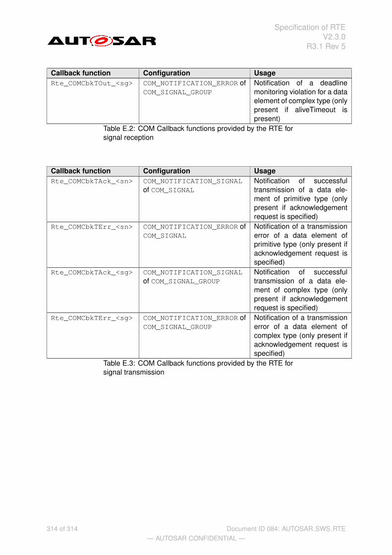
Specification of RTEV2.3.0
R3.1 Rev 5
Callback function Configuration UsageRte_COMCbkTOut_<sg> COM_NOTIFICATION_ERROR of
COM_SIGNAL_GROUPNotification of a deadlinemonitoring violation for a dataelement of complex type (onlypresent if aliveTimeout ispresent)
Table E.2: COM Callback functions provided by the RTE forsignal reception
Callback function Configuration UsageRte_COMCbkTAck_<sn> COM_NOTIFICATION_SIGNAL
of COM_SIGNALNotification of successfultransmission of a data ele-ment of primitive type (onlypresent if acknowledgementrequest is specified)
Rte_COMCbkTErr_<sn> COM_NOTIFICATION_ERROR ofCOM_SIGNAL
Notification of a transmissionerror of a data element ofprimitive type (only present ifacknowledgement request isspecified)
Rte_COMCbkTAck_<sg> COM_NOTIFICATION_SIGNALof COM_SIGNAL_GROUP
Notification of successfultransmission of a data ele-ment of complex type (onlypresent if acknowledgementrequest is specified)
Rte_COMCbkTErr_<sg> COM_NOTIFICATION_ERROR ofCOM_SIGNAL_GROUP
Notification of a transmissionerror of a data element ofcomplex type (only present ifacknowledgement request isspecified)
Table E.3: COM Callback functions provided by the RTE forsignal transmission
314 of 314— AUTOSAR CONFIDENTIAL —
Document ID 084: AUTOSAR SWS RTE