specifications - iecsiecs.com/wp-content/uploads/iecs/specs/cableconcrete/iecs_cable... · a....
TRANSCRIPT

A. DESCRIPTION
Specifications
Cable Concrete®
is an articulated concrete block revetment system, developed by
International Erosion Control Systems, to control various types of erosion due to water,
wind, or vehicular traffic.
This system is made up of 2.44m x 4.88m long (8’x16’) mats placed side by side and
clamped together to provide one homogeneous erosion protection system. Smaller mats
are available as required.
The mats consist of concrete blocks interlocked by integrally woven stainless steel cables,
which are poured within each block. Geotextile fabric is attached to the base of each
concrete mat. The blocks typically have 292.10mm (11.5”) square top faces and
393.70mm (15.5”) square bottoms. Variations between the mat systems are the block
heights and weights.
B. CONCRETE
The concrete shall meet the requirements of CSA A23.1/A23.2 for materials, testing, and
methods of construction. The concrete mix shall be designed to meet CSA A23.1 Exposed
Class C-2 requirements. The minimum required concrete strength shall be 25 MPA @ 28 days
with a minimum of 5-8 % air entrainment throughout.
C. CABLES
The cables shall be made of type 302/304 stainless steel aircraft cable, 1x19 construction.
Cables shall be integral (poured into) to the concrete block and shall traverse through each
block in both longitudinal and lateral directions, providing a flexible interlocked system.
STAINLESS STEEL CABLE
System Lengthwise
mm inches
Widthwise
mm inches
CC35 4 5/32” 4 5/32”
CC45 4 5/32” 4 5/32”
CC70 4.8 3/16” 4.8 3/16”
SYSTEM
Minimum
BLOCK WEIGHT
Minimum
BLOCK HEIGHT
Open
Area %
kg/sm lbs/sf mm inches
CC 35 180.65-195.30 37-40 114.3-127.0 4 ½ -5 20
CC 45 229.47-253.88 47-52 139.7-152.4 5 ½ -6 20
CC 70 351.53-380.83 72-78 215.9-228.6 8 ½ -9 20

D. GEOTEXTILE
The standard geotextile material used is a needle punched non-woven fabric which is
attached to the underside of the mats. An overlap shall be incorporated on three sides. The
overlap provides area for the adjoining mats to be placed upon and prevent undermining
of the erosion control system.
It should be noted that when different geotextile weights are used and or when additional
overlap area is added to the mat, additional cost adjustments shall be made.
E. CLAMPS
Sufficient malleable or stainless steel cable clamps may be used to connect adjoining
Cable Concrete®
mats. The standard placement of clamps shall be placed on 1.22m (4’) centres connecting adjoining mats together. Clamps are recommended in applications exceeding 3.05m (10’) per second. When placing clamps under existing water, the manufacture will specify a clamp for the
condition.
F. ANCHORING
Cable Concrete®
mats are designed to take certain velocities in certain slope and bedding
situations. This information is founded on engineered flume testing. The data shows
maximum limits of the mat system, based on unanchored mats.
Anchoring Cable Concrete®
mats offer additional safety to the erosion protection system.
If a situation arises where velocities may exceed maximum limits of a system, or if slopes
of 1.5:1 or greater are encountered, then anchoring becomes an item to be specified by the
governing project engineer.
G. INSTALLATION
Installation equipment shall have a lifting capacity, capable of completely lifting the concrete
mat and the lifting bar during unloading, stockpiling and installing etc.
Prepared areas shall be graded to a smooth plane finish. Any roots, debris and stones must be
removed and regarded. Specified geotextile to be placed according to manufacturing.
recommendations. There shall not be any dragging, tearing or damaging of the geotextile. The
mats shall be laid on the geotextile in such a manner to produce a smooth plane surface.
Intimate contact with the subsurface is critical to the systems performance in the field. The gap between each mat shall not be greater than 2”, preferably 1” or it must be closed using
a cement mixture.
It is recommended that after the installation of the mat system, that it be covered with
desired backfill. If vegetation is required, the mat system shall be backfilled and seeded.
This will allow moisture to traverse back and forth from sub grade to vegetation.
Vegetation will lend support and an even grade for maintenance vehicles (mowers) to
traverse over it. Any surface application should not be placed prior to the inspection of
the systems clamping and anchoring.
H. PAYMENT
Payment shall be by the square meter and shall include Cable Concrete®
mats and
manufacturer’s recommended geotextile.
Stainless Steel cable clamps, anchors, lifting bar rental and delivery are separate cost
items.
Upgrades or additional items shall be considered additional costs

.
TYPICAL UNIT
DEPTHS
INTERNATIONAL EROSION CONTROL SYSTEMS INC.
22295 Hoskins Line, Phone: 800-821-7462 Rodney ON, N0L 2C0 Fax: 866-496-1990 www.iecs.com
Typical Unit Depth

KEY IN DETAIL
TOPOFSLOPE
OPTION1
NON-ERODIBLE
BACK-FILLED
CABLECONCRETE ® MATTRESS
ATTACHED
GEOTEXTILE
TOPOFSLOPE
OPTION2
NON-ERODIBLE
BACK-FILLED
CABLECONCRETE ® MATTRESS
ATTACHED
GEOTEXTILE
DrawingN.T.S.
International Erosion
Control Systems Inc. 22295 Hoskins Line, Rodney,
ON, N0L 2C0
PH:800-821-7462
FX:866-496-1990
Tracking DrawnBy: McCoyDraftingandDesign,LLC.
Customer: CheckedBy: CharlieChase
Project: Date: December9,2010
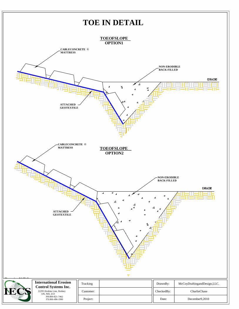
TOE IN DETAIL
TOEOFSLOPE
OPTION1
CABLECONCRETE ® MATTRESS
NON-ERODIBLE
BACK-FILLED
ATTACHED
GEOTEXTILE
CABLECONCRETE ® MATTRESS TOEOFSLOPE
OPTION2
NON-ERODIBLE
BACK-FILLED
ATTACHED
GEOTEXTILE
DrawingN.T.S. International Erosion
Control Systems Inc. 22295 Hoskins Line, Rodney
ON, N0L 2C0
PH:800-821-7462
FX:866-496-1990
Tracking DrawnBy: McCoyDraftingandDesign,LLC.
Customer: CheckedBy: CharlieChase
Project: Date: December9,2010

Installation Cost Estimate
When estimating the placement of Cable Concrete® in typical applications, here are some
guidelines to follow:
On gentle slopes of 3:1 or less, trackhoe with operator and two labourers to place-
11-13 (1.22m x 4.88m) mats, approximately 60 SM/hr or
8-10 (2.44m x 4.88m) mats, approximately 115 SM/hr.
On slopes of 2:1 to 1.5:1, trackhoe with operator and three labourers to place (the 3rd
labourer to unhook the mats from the lifting bar at the top of the slope).
10-12 (1.22m x 4.88m) mats, approximately 50 SM/hr or
7-9 (2.33m x 4.88m) mats, approximately 90 SM/hr.
Allow one labourer to clamp and anchor the placed Cable Concrete® mats. Approximately 1
man/10 min. to drive, set and clamp each anchor, 1 man/3min. per clamp to connect adjoining
mats together.
The above estimations are based on placing Cable Concrete® mats on a prepared base.
Use your local machine and labour rates.
Installation equipment shall have a lifting capacity, capable of completely lifting the concrete
mats and the lifting bar during unloading, stockpiling, installing etc. Prepared areas shall be
graded to a smooth plane finish. Any roots, debris and stones must be removed and re-graded.
There shall not be any dragging, tearing or damaging of the geotextile. The mats shall be laid in
such a manner to produce a smooth plane surface. Intimate contact with the subsurface is critical
to the systems performance in the field. The gaps between each mat shall not be greater than 2”,
preferably 1”, or the gap must be closed using a cement mixture.
It is recommended that after the installation, the mat system be covered with desired backfill. If
vegetation is required, the mat system shall be backfilled and seeded. This will allow moisture to
traverse back and forth from sub grade to vegetation. Vegetation will lend support and an even grade
for maintenance vehicles (mowers) to traverse over it. Any surface application should not be placed
prior to the inspection of the systems clamping and anchoring.
These are recommended guidelines only.

PROFILEVIEW
CABLECONCRETE ® MAT1
MATEND
LOOPS
CABLECONCRETE ® MAT2
ATTACHED
GEOTEXTILE
CABLE
CLAMP
WHENPLACINGTHEMATS,THEGAPBETWEENTHEMATSSHOULDNOTBEANYLARGERTHANA50mm(2")
MAXIMUM.IFTHEMATSAREPLACEDWITHALARGERSPACETHAN50mm(2"),ITISRECOMMENDEDTOGROUT
THESEAMBETWEENTHEMATS.
PLANVIEW
CABLECLAMP
NOTE:
CABLE CLAMPS ARE MADE OF A U-BOLT,
ACOVERSADDLE,ANDTWONUTS.
POSITIONCABLECLAMPASSNUGTOTHE
BASEOFTHECONCRETEBLOCKBYSLIDING
CABLECLAMPDOWNTOTHEADJACENT
LOOPS,THENTIGHTENCLAMPSECURELY.
International Erosion Control
Systems Inc.
INTERNATIONAL EROSION CONTROL SYSTEM INC.
22295 Hoskins Line, Phone:800-821-7462 Rodney ON, N0L 2C0 Fax: 866-496-1990
www.iecs.com
CABLE
CONCRETE® MAT1
CABLE
CONCRETE® MAT2

ARROWHEAD EARTH ANCHORS
TOP VIEW
FRONT VIEW
REAR VIEW
The Chasco Arrowhead is a state of the art anchoring
system with a variety of uses. Rated at 5500 lbs., the
Arrowhead is ideal for anchoring cable concrete , erosion
mats , concrete gabion retaining walls , mobile homes, portable
classrooms, sheds , fences and other equipment such as
oil tanks and towers. Unlike other anchoring devices, the
Arrowhead doesn't require the use of stems, rods or pipes,
therefore there are no rods protruding from the ground when
the anchor is set. And because it can be installed quickly by
means of common tools, it's quite simple to use.
The galvanized Arrowhead and stainless steel cable prevent rust,
giving it increased durability.
The standard anchor has an overall length of 48" with extra length
supplied as required.
Manufactured by B & R Stamping
Oakville , Ontario
905-847-5294
NOT TO SCALE

DRIVE ANCHOR MINIMUM OF 1
METER INTO UNDISTURBED SOILS
CAPABLE OF HOLDING SPECIFIED ANCHOR STRENGTH

ANALYSIS SHEET
Date:
Project Name:
Project Location:
Engineer:
OPEN CHANNEL OR FLOW APPLICATION Imperial Metric
Maximum Expected Flow, (cfs)
Maximum Expected Velocity, (fps)
Channel Bed Slope (%)
Channel Side Slope (Ratio)
Type of Flow –normal, overtopping, sub critical,
hydraulic jump, impinging, bridge/culvert,
undulating Transcritical
Bed Width, (ft.) bottom
Alignment-straight, moderate, severe, extreme
Radius at the Crest (ft.)
Channel/Chute Length, (ft.)
Channel Depth, (ft.)
Top Width of Channel (ft.)
Outlet Source (ie: river, manhole)
Soil Type and Related Conditions
SHORELINE APPLICATION
Bank Slope
Water Depth of Protection, (ft.)
Wave Height, (ft.)
Wave Lengths, (ft.)
Soil Type and Related Conditions