specifications and contract documents …...substation control switchgear housin, 16350 mv...
TRANSCRIPT
SPECIFICATIONS AND CONTRACT DOCUMENTS
METAL CLAD SWITCHGEAR
FOR
GATEWAY SUBSTATION
CITY OF MURFREESBORO
MURFREESBORO ELECTRIC DEPARTMENT
MURFREESBORO, TENNESSEE
engineers • planners
402 BNA Drive, Suite 208
Nashville, TN 37217-2518
JOB NO.: 81597.9
DATE: November, 2016
081716 81597.9
M092896-EU CONTENTS 00003 - 1
DOCUMENT 00003
CONTENTS
DIVISIONS 0 and 1 - CONTRACT DOCUMENTS AND GENERAL REQUIREMENTS
Pages
00001 TITLE SHEET 1
00002 CERTIFICATIONS 1
00003 TABLE OF CONTENTS 1
00004 LIST OF DRAWINGS, TABLES & SCHEDULES 2
00021 INVITATION TO BIDDERS 1
00101 INSTRUCTIONS TO BIDDERS 2
00301 PROPOSAL 6
00531 MATERIALS CONTRACT 3
00711 GENERAL CONDITIONS 7
00811 SUPPLEMENTARY CONDITIONS 2
00900 ADDENDA 1
01040 PROJECT COORDINATION 2
01090 REFERENCE STANDARDS 2
01301 SUBMITTALS 2
01341 SHOP DRAWINGS 4
01721 PROJECT RECORD DOCUMENTS 3
DIVISION 16 - ELECTRICAL
16162 SUBSTATION CONTROL AND SWITCHGEAR HOUSING 18
16350 MV METAL-CLAD SWITCHGEAR 21
16350D MV METAL-CLAD SWITCHGEAR – DATA SHEET 9
16632 CENTRAL NICKEL-CADMIUM BATTERY SYSTEM 5
END OF DOCUMENT
061716 81597.9
M092096-EU LIST OF DRAWINGS, TABLES & SCHEDULES 00004 - 1
DOCUMENT 00004
LIST OF DRAWINGS, TABLES & SCHEDULES
The following is a list of Contract Drawings which this contract is to be based. These drawings are
entitled Gateway 161/13kV Substation and dated October 2016 with revision dates (if any), as
noted. They will be supplemented by additional shop and dimensional drawings of materials and
equipment and other drawings where specified.
Drawing Revision
Number Sub-Title Date
E1.1 SINGLE LINE DIAGRAM
E10.1 SWITCHGEAR PLAN VIEW AND ELEVATIONS
E10.2 13 kV SWITCHGEAR PANEL ELEVATIONS
CUBICLES 1 & BATTERY ROOM
E10.3 13 kV SWITCHGEAR PANEL ELEVATIONS CUBICLES 2-4
E10.4 13 kV SWITCHGEAR PANEL ELEVATIONS CUBICLES 5-8
E10.5 13 kV SWITCHGEAR EXTERIOR ELEVATION FRONT& REAR
E10.6 13 kV SWITCHGEAR EXTERIOR ELEVATION LEFT & RIGHT SIDE
E10.7 AC/DC PANEL DIAGRAM
E10.8 MISCELLANEOUS DIAGRAM
E10.9 IPU/CRU SCHEMATIC
E12.0.1 CURRENT THREE LINE DIAGRAM
E12.0.2 CURRENT THREE LINE DIAGRAM
E12.0.3 CURRENT THREE LINE DIAGRAM
E12.0.4 CURRENT THREE LINE DIAGRAM
E12.0.5 CURRENT THREE LINE DIAGRAM
E12.0.6 POTENTIAL THREE LINE DIAGRAM
E12.0.7 POTENTIAL THREE LINE DIAGRAM
E12.0.8 POTENTIAL THREE LINE DIAGRAM
E12.0.9 POTENTIAL THREE LINE DIAGRAM
E12.0.10 POTENTIAL THREE LINE DIAGRAM
E12.1.1 TRANSFORMER BANK 1 SCHEMATIC DIAGRAM 9187
E12.1.2 TRANSFORMER BANK 1 & 914A OVERCURRENT
SCHEMATIC DIAGRAM 9150/51-1
E12.1.3 CIRCUIT SWITCHER 914B CONTROL SCHEMATIC 9186
CONTACT DEVELOPMENT
E12.1.4 161 kV UNDEGROUND CABLE DIFFERENTIAL SCHEMATIC 9087-1
E12.2.1 CIRCUIT BREAKER 214 CONTROL SCHEMATIC 2150/51
E12.3.1 CIRCUIT BREAKER 224 CONTROL SCHEMATIC 2250/51
061716 81597.9
M092096-EU LIST OF DRAWINGS, TABLES & SCHEDULES 00004 - 2
E12.4.1 TIE CIRCUIT BREAKER 204 SCHEMATIC DIAGRAM
E12.4.2 COMMUNICATIONS SCHEMATIC
E12.4.3 COMMUNICATIONS SCHEMATIC
E12.4.4 9130 ANNUNCIATOR SCHEMATIC SEL-2523
E12.5.1 CUBICLE 5 DC
E12.5.2 TVA U.F., U.V. LOAD SHED SCHEMATIC DIAGRAM
E12.5.3 TVA U.F., U.V. LOAD SHED SCHEMATIC DIAGRAM
E12.6.1 CIRCUIT BREAKER 234 CONTROL SCHEMATIC 2350/51
E12.7.1 CIRCUIT BREAKER 244 CONTROL SCHEMATIC 2450/51
E12.8.1 TRANSFORMER BANK 2 SCHEMATIC 9287
E12.8.2 TRANSFORMER BANK 2 & CIRCUIT SWITCHER 924A
OVERCURRENT SCHEMATIC 9250/51-1
E12.8.3 CIRCUIT SWITCHER 924B CONTROL SCHEMATIC 9286
CONTACT DEVELOPMENT
E12.8.4 161 kV UNDEGROUND CABLE DIFFERENTIAL SCHEMATIC 9087-2
E2.1 GENERAL ARRANGEMENT PLAN
C2.1 GRADING AND DRAINAGE PLAN
END OF DOCUMENT
081716 81597.9
M080196-EU INVITATION TO BIDDERS 00021 - 1
DOCUMENT 00021
INVITATION TO BIDDERS
Sealed proposals for a 15kV Metal Clad Switchgear for the Gateway Substation will be received by
the Murfreesboro Electric Department at their office in Murfreesboro until 2:00 PM local time on
November 30, 2016 and immediately thereafter will be opened, and publicly read.
Proposals shall be received by:
Murfreesboro Electric Department
ATTN: Steve Sax, General Manager
205 North Walnut Street
Murfreesboro, Tennessee 37130
Metal-Clad Switchgear Bid Opening: November 30, 2016
The Owner’s preferred carrier is FedEx®.
The Owner reserves the right to reject any or all bids and to waive any informalities or technicalities
therein.
No Bidder may withdraw a bid for a period of sixty (60) days after the date set for opening of bids.
By: Mr. Steve Sax, General Manager
Murfreesboro Electric Department
END OF DOCUMENT
081716 81597.9
M072712-EU INSTRUCTIONS TO BIDDERS 00101 - 1
DOCUMENT 00101
INSTRUCTIONS TO BIDDERS
Each Bidder shall examine carefully the site of the work to be acquainted with working conditions
and all difficulties that may be involved therein, and shall examine carefully all drawings,
specifications, and other contract documents to be familiar with all of the requirements, terms, and
conditions thereof. Any information relating to the work furnished by the Owner or others, or
failure to make these examinations shall in no way relieve any Bidder from the responsibility of
fulfilling all of the terms of the contract.
The Proposal provides for quotation of a price for one or more bid items, which may be lump sum
bid prices, alternate bid prices or a combination thereof. No payment will be made for items not
set up in the Proposal, unless otherwise provided by contract amendment. All Bidders are
cautioned that they should include in the prices quoted for the various bid items all necessary
allowances for the performance of all work required for the satisfactory completion of the Project.
Bidder is cautioned to verify the completeness of this specification package as listed in Document
00003 - CONTENTS.
Bidder will submit two (2) copies of Document 00301 - PROPOSAL and all supporting documents
specified.
Bids that are sent by U.S. Postal Service or private carrier shall be clearly marked "BID ENVELOPE
ENCLOSED." The bid shall be sealed in a separate envelope and shall have the following
information, shown on the outside of the envelope.
BID FOR: One 15 kV Metal-Clad Switchgear
BID DUE: November 30, 2016 - 2:00 PM CST
OWNER: Murfreesboro Electric Department
ATTN: Steve Sax, General Manager
205 North Walnut Street
Murfreesboro, TN 37130
The Engineer for this project is:
Allen & Hoshall
Engineers Planners
STREET: BNA Corporate Center
402 BNA Drive, Suite 208
Nashville, Tennessee 37217-2518
PHONE: (615) 399-2661
FAX: (615) 399-2657
CONTACT: Jody Cathey
ALTERNATE: Tyler Vowell
The Engineer will represent the Owner in all matters pertaining to this project, including but not
limited to, answering technical questions of prospective bidders, recommendation of awards,
acceptance of shop drawings and similar documents, and approval of invoices prior to payment by
the Owner.
081716 81597.9
M072712-EU INSTRUCTIONS TO BIDDERS 00101 - 2
CHECKLIST FOR BIDDERS - Submit two (2) copies of Document 00301 - PROPOSAL and all
supporting documents as specified:
DOCUMENT 00101: Bid Envelope Information: Enter on sealed bid envelope
DOCUMENT 00301: Date
DOCUMENT 00301: Bid Price:
Base Bid
Option 1
Option 2
DOCUMENT 00301: Equipment Maintenance Requirements
DOCUMENT 00301: Place of Manufacture
DOCUMENT 00301: Alternate Delivery Date and price reduction (if any)
DOCUMENT 00301: Shop Drawing Schedule
DOCUMENT 00301: Required Submittal Data
DOCUMENT 00301: Addenda (if any)
DOCUMENT 00301: Exceptions to the Specifications (if any)
DOCUMENT 00301: Signature
END OF DOCUMENT
081716 81597.9
M061596-EU R091412 PROPOSAL FORM 00301 - 1
DOCUMENT 00301
PROPOSAL FORM
November 30, 2016
To: Mr. Steve Sax, General Manager
Murfreesboro Electric Department
205 North Walnut Street
Murfreesboro, TN 37130
Gentlemen:
The undersigned, hereinafter called the "Materialman", hereby proposes to sell and deliver to
Murfreesboro Electric Department hereinafter called the "Owner" upon the terms and conditions
herein stated, the material specified in the attached Specifications dated November, 2016, for the
following sum:
BASE BID:
ITEM QUANTITY DESCRIPTION TOTAL BID PRICE
1 1 Metal-Clad Switchgear $________________
2 1 Performance Bond $________________
3 1 (Optional) Spare Power Circuit Breaker $________________
PROJECT LOCATION AND SCHEDULE:
Delivery Site: 259 Robert Rose
Murfreesboro, TN 37153
Delivery Period: June 26 thru 28 2017. Delivery
Delivery Constraints: Units shall be delivered to the Destination beginning at 11:00 p.m. and
completed before 4:00 a.m. Materialman shall provide Owner with a copy
of its TDOT permit immediately after receipt, Owner requires Materialman’s
TDOT permit to coordinate a local permit with the City of Murfreesboro.
The Materialman is responsible for any additional costs due to delays in
Owner’s receipt of the TDOT permit. Owner will identify and obtain
permission for use of a temporary parking area near the Destination.
Materialman will need to confirm the temporary parking area is sufficient
for the purpose.
Field Assembly Completion Date: June 30, 2017
Site Conditions: New Substation, compact.
An alternate Delivery Period of __________ to ____________ is proposed by the Materialman. If this
alternate Delivery Date is accepted by the Owner, a bid price DEDUCT per unit of
$___________________ is offered.
081716 81597.9
M061596-EU R091412 PROPOSAL FORM 00301 - 2
The Materialman shall provide the switchgear base shop drawing detailing all duct entrance location
and size, as specified in Section 01341 – SHOP DRAWINGS, _________ weeks after receipt of
Notice of Award.
The Materialman shall provide shop drawings, as specified in Section 01341 – SHOP DRAWINGS,
_________ weeks after receipt of order.
The Materialman shall provide "FOR CONSTRUCTION" drawings at least 6 weeks prior to shipping.
Option 1
The Owner requests an adder for a 1-year extension to the warranty specified in Sections 16162
SUBSTATION CONTROL SWITCHGEAR HOUSIN, 16350 MV METAL-CLAD SWITCHGEAR and
16632 CENTRAL NICKEL-CADMIUM BATTERY SYSTEM. During this additional 1-year period, the
Materialman’s responsibilities are identical to those specified in the respective Sections. The BASE
Proposal price ADDER per unit is $_______________________.
Option 2
The Owner requests an adder for a 4-year extension to the warranty specified in Sections 16162
SUBSTATION CONTROL SWITCHGEAR HOUSIN, 16350 MV METAL-CLAD SWITCHGEAR and
16632 CENTRAL NICKEL-CADMIUM BATTERY SYSTEM. During this additional 4-year period, the
Materialman’s responsibilities are identical to those specified in the respective Sections. The BASE
Proposal price ADDER per unit is $_______________________.
LABOR RELATIONS:
The nearest labor contract expiration date associated with the design, manufacture, delivery or
installation is __________________.
GENERAL:
In submitting this Proposal, the Materialman agrees as follows:
The prices set forth herein do not include any sums which are or may be payable by the
Materialman on account of taxes imposed by any taxing authority upon the sale, purchase, or use
of the equipment. If any such tax is applicable to the sale, purchase, or use of the equipment, the
amount thereof shall be added to the purchase price and paid by the Owner.
The Materialman agrees to the terms and conditions of the Document 00531 - MATERIALS
CONTRACT.
The prices set forth herein are firm if accepted by the Owner within the period specified in
Document 00021 - INVITATION TO BIDDERS and shall include the cost of:
1. Delivery to the job site.
2. Offloading onto an Owner furnished concrete pad.
3. Assembly, if any, to provide the Owner with material ready for external connection. 4. Field Service Representative for inspection, testing, and certification.
081716 81597.9
M061596-EU R091412 PROPOSAL FORM 00301 - 3
The GENERAL CONDITIONS and SUPPLEMENTARY CONDITIONS describe the Owner’s
requirements as to Surety Bonds. When the successful Bidder delivers the executed Materials
contract to the Owner, it must be accompanied by the required Surety Bond.
DELIVERY AND INSTALLATION:
The material shall be delivered to the Delivery Site during the Delivery Period specified above. The
Delivery Period defines the time during the project schedule from completion of the concrete pad
until other project tasks could make the pad inaccessible. Delivery outside the specified Delivery
Period could result in liquidated damages being assessed. Field assembly shall be completed on or
before the Field Assembly Completion Date.
The Materialman shall be responsible for securing all permits required for shipping to the Delivery
Site and shall be responsible for any damages to road and utilities or other damages caused by the
Materialman or his Delivery Agent during shipment to Delivery Site.
Notice of Shipment - The Materialman shall notify the Owner and Engineer at the following times:
1. 10 days prior to shipment.
2. 24 hours prior to shipment.
3. 24 hours prior to delivery.
Failure to provide notice shall result in Materialman being responsible for any demurrage charges
resulting from the unavailability of equipment to unload equipment.
The Materialman agrees that all requests for time extensions shall be in writing, and that only such
time extensions as are granted by the Owner in writing shall be considered.
Time is of the essence in order for the Owner to comply with established construction schedules.
Should the Materialman fail to complete the terms of this Proposal by the Submittal and Completion
dates, after all time extensions granted by the Owner have been added, then in that event the
Owner shall have and is hereby given the right to deduct and retain out of such monies which may
then be due, or which may become due and payable to the Materialman, the DAMAGE AMOUNT
per calendar day as liquidated damages for each and every day that Certification is delayed beyond
the Completion Date. The Materialman and Owner agree that liquidated damages are for costs
associated with project delay and not as a penalty and that proof of such losses or damages shall
not be required. The DAMAGE AMOUNT shall be $ 300 per day.
The 161 kV transmission line will be energized during delivery. The three phases are identified as
“OHP” on drawing E2.1.
BID ATTACHMENTS:
Additional information and drawings shall be attached to and become a part of this Proposal
including, but not be limited to, the following:
1. Material Outline Drawings.
2. Material Dimensions and Weights.
3. Proposal requirements, as outlined in the technical sections.
4. A schedule of field tests, if different from those specified in the Technical Section(s).
5. The qualifications of the Materialman’s Field Services Representative for field inspection,
081716 81597.9
M061596-EU R091412 PROPOSAL FORM 00301 - 4
testing and certification shall be attached to this proposal. Include the name of the
proposed field service firm, if these services are not supplied by employees of the
manufacturer. A schedule of field tests, applicable ANSI standards and test limits shall
be submitted by the Materialman.
6. List of projects completed in the last year with contact information.
Failure to submit bid evaluation data as specified can lead to bid rejection.
The Materialman shall submit bids on this PROPOSAL FORM. Submit (2) two unaltered copies of
the PROPOSAL FORM with all blank spaces completed. Each completed PROPOSAL FORM should
also include a copy of the required attachments. There shall be no exceptions for basic bid
submitted by the Materialman; however, an alternate, with exceptions, may be bid as an
attachment to a basic bid.
EVALUATION OF BIDS:
In determining the lowest responsible and responsive bid and deciding the award of an order, the
Owner will consider, in addition to the price quoted on this PROPOSAL FORM, the following:
1. Stated exceptions to the specifications.
2. Warranty.
3. Delivery time.
4. Work history on previous projects.
The bid prices submitted for spare parts will not be used in the evaluation.
Title of each equipment item shall pass to the Owner upon:
1. Delivery and placement of equipment onto foundation at location specified.
2. Satisfactory inspection for in transit damage.
3. Satisfactory installation and field test.
4. Acceptance by the Owner following completion of Item 3.
5. Payment: See Document 00531 – MATERIALS CONTRACT, Article II Payment.
The Materialman acknowledges that he has received the following Addenda (insert Addenda
number(s) and date(s) or NONE):
ADDENDUM NUMBER DATE
_________________________________________ _____________
_________________________________________ _____________
081716 81597.9
M061596-EU R091412 PROPOSAL FORM 00301 - 5
EXCEPTIONS: Any and all exceptions that the Materialman takes to the attached specifications
shall be itemized on this proposal page even though the exceptions may be covered elsewhere in
the bid materials. The bidder shall indicate to which items exceptions apply or indicate no
exceptions.
Specification Section
Associated with EXCEPTION Description of Exception
081716 81597.9
M061596-EU R091412 PROPOSAL FORM 00301 - 6
It is understood by the undersigned that the Owner retains the privilege of accepting or rejecting all
or any part of this PROPOSAL FORM and to waive any informalities or technicalities therein.
MATERIALMAN:
BY: TITLE:
MAILING ADDRESS: DATE:
TELEPHONE:
FAX:
E-MAIL:__
STREET ADDRESS:
OVERNIGHT SHIPMENT ADDRESS:
PRINCIPAL CONTACT TELEPHONE:
E-MAIL:__
ALTERNATE CONTACT TELEPHONE:
E-MAIL:__
END OF DOCUMENT
081716 81597.9
M030597-EU MATERIALS CONTRACT 00531 - 1
DOCUMENT 00531
MATERIALS CONTRACT
THIS MATERIALS CONTRACT (“Agreement”) made as of ____________, between the City of
Murfreesboro, a Tennessee municipal corporation (the "Owner"), organized and existing under the laws
of the State of Tennessee and _______________, (the "Materialman"), a corporation organized and
existing under the laws of the State of ________________.
WHEREAS, the Owner and the Materialman desire to enter into this contract for the furnishing of
materials, supplies and equipment (hereinafter called "Materials") for the Project,
NOW THEREFORE, in consideration of the mutual undertakings herein contained, the parties hereto
agree as follows:
ARTICLE I - GENERAL
SECTION 1. The Materialman agrees to sell and deliver to the Owner and the Owner agrees to
purchase and receive from the Materialman the following Materials in accordance with the provisions of
the Table of Contents, Invitation to Bidders, Bidding Instructions, Materialman's Proposal, General
Conditions, Supplementary Conditions, Specifications and other items, attached hereto and made part
hereof:
One Metal-Clad Switchgear
Total Contract Price:
ARTICLE II - PAYMENT
Upon the shipment of any Materials hereunder, the Materialman shall submit to the Owner a detailed
invoice duplicate of the Materials shipped. Within 30 days after delivery and acceptance of the
Materials, the Owner shall make payment in the amount of 95 percent of the value of the equipment
and materials delivered at the destination but not prior to the delivery dates contained in the
specifications. After energization of the equipment or within four (4) calendar months after delivery,
whichever is first, the Owner will promptly pay the additional 5 percent due.
ARTICLE III - DEFECTIVE MATERIALS AND WORKMANSHIP
SECTION 1. All materials furnished hereunder shall be subject to the inspection, tests, and approval of
the Owner and the Materialman shall furnish all information required concerning the nature or source of
any Materials and provide adequate facilities for testing and inspecting the Materials at the Plant of the
Materialman.
SECTION 2. The materials furnished hereunder shall become the property of the Owner when delivery
at the specified location is made; no transit damage is noted after delivery; Materialman has
satisfactorily installed, tested and certified the materials are ready to be placed in service; Owner has
accepted installation and tests completed by Materialman; and payment, as defined in Article II, has
been made. Owner may reject any such materials as do not comply with the Specifications for
materials and warranties of the Materialman and manufacturers and any defective materials either
before or after incorporation of such materials into the Project; provided such rejection is made in
accordance with Warranty requirements of the attached technical section of this Specification. Upon
any such rejection, the Materialman shall replace the rejected Materials with Materials complying with
the Specifications for Materials and warranties at the original delivery destination(s). The Owner shall
return the rejected materials at the same destination(s). In the event of the failure of the Materialman
081716 81597.9
M030597-EU MATERIALS CONTRACT 00531 - 2
to replace rejected Materials, the Owner may make such replacement and the cost and expense thereof
shall be paid by and recoverable from the Materialman.
ARTICLE IV - MISCELLANEOUS
SECTION 1. All manufacturer's guaranties of Materials shall be transferred and assigned to the Owner
upon delivery of any Materials and before payment is made for such Materials. Such guaranties shall
be in addition to those required of the Materialman by other provisions of this contract.
SECTION 2. The Materialman shall hold harmless and indemnify the Owner, its agents and employees,
from any and all claims, suits and proceedings for infringement of any patent or patents covering
Materials purchased hereunder. The Materialman shall defend any suit or proceeding brought against
the Owner, its agents or employees, based upon a claim that the materials or any part thereof
constitute an infringement of any patent, or if the Materialman shall fail to defend such suit or
proceeding, the Owner may do so and the Materialman shall make reimbursement for the expense of
such litigation. If the Materials, or any part thereof, are held to constitute infringement and the use
thereof is enjoined the Materialman shall, at its own expense, either procure for the Owner the right to
continue to use the Materials, or such part thereof, or shall replace the Materials, or such part thereof,
with non-infringing materials.
SECTION 3. Simultaneously with the final payment to the Materialman, as provided herein, the
Materialman shall deliver to the Owner duplicate original releases of lien of subcontractors, if any.
SECTION 4. In the event that any of the provisions of this contract are violated by the Materialman or
by any of the Materialman's subcontractors, the Owner may serve a written notice of intention to
terminate such contract upon the Materialman, which notice shall specify the reasons therefor. Unless
within ten (10) days after the serving of such notice upon the Materialman such violation shall cease
and an arrangement for the correction thereof satisfactory to the Owner be made, this contract shall,
upon the expiration of the said ten days, cease and terminate. In the event of any such termination,
the Owner may purchase the Materials necessary for complete performance of this contract for the
account and at the expense of the Materialman, and the Materialman shall be liable to the Owner for
any excess cost occasioned thereby. The foregoing shall be in addition to every right or remedy now
or hereafter existing at law or in equity or by statute.
SECTION 5. Each and all of the covenants and agreements, herein contained shall extend to and be
binding upon the successors and assigns of the parties hereto. However, the Materialman shall not
assign this contract or any part thereof or enter into any contract with any person, firm or corporation
for the performance of the Materialman's obligations hereunder, or any part thereof, without the
approval in writing, of the Owner.
081716 81597.9
M030597-EU MATERIALS CONTRACT 00531 - 3
IN WITNESS WHEREOF, the parties hereto have caused this Agreement to be executed by their duly
authorized representatives all as of the day and year first above written.
Owner: City of Murfreesboro Materialman:
Murfreesboro Electric Department
205 North Walnut Street
Murfreesboro, TN 37130
Signed: Signed: _______________________________________
Type/Print: Type/Print: _____________________________________
Title: Title: ___________________________________________
END OF DOCUMENT

081716 81597.9
M061596-EU GENERAL CONDITIONS 00711 - 1
DOCUMENT 00711
GENERAL CONDITIONS
TABLE OF CONTENTS
1. DEFINITIONS ..................................................................................................... 2
2. ENGINEER/ARCHITECT'S DECISION ..................................................................... 2
3. DRAWINGS AND SPECIFICATIONS ..................................................................... 3
4. STANDARD PUBLICATIONS ............................................................................... 3
5. STANDARD EQUIPMENT AND EQUIPMENT INSTALLATION ................................... 3
6. STANDARDS FOR MATERIALS ............................................................................ 4
7. PATENTS ......................................................................................................... 4
8. CONTRACT SECURITY ....................................................................................... 4
9. SUBCONTRACTING ............................................................................................ 4
10. LIQUIDATED DAMAGES ..................................................................................... 5
11. NOTICES AND SERVICE THEREOF ....................................................................... 5
12. RIGHTS OF THE OWNER TO TERMINATE CONTRACT ............................................ 6
13. ASSIGNMENT OF CONTRACT ............................................................................. 6
14. WARRANTY ...................................................................................................... 6
15. MODIFICATIONS TO GENERAL CONDITIONS ........................................................ 7
081716 81597.9
M061596-EU GENERAL CONDITIONS 00711 - 2
DOCUMENT 00711
GENERAL CONDITIONS
1. DEFINITIONS
A. The word "Owner" means the person(s), or organization, or municipality to which the
Proposal is addressed.
B. The words "Engineer", "Architect", "Engineer/Architect" mean ALLEN & HOSHALL,
Architects Engineers.
C. The word “Materialman”, “Contractor”, or “Bidder” means the successful Bidder to whom
the contract is awarded.
D. The words "install", "furnish", "provide", or words of like import mean the Materialman
shall install, furnish, or provide, and similarly the words "approved", "authorized",
"required", "satisfactory", "acceptable", or words of like import mean approved by,
authorized by, required by, satisfactory to, or acceptable to the Engineer/Architect, unless
otherwise expressly stated.
E. The words "indicated", "shown", "detailed”, or "scheduled" mean indicated, shown,
detailed, or scheduled on the contract documents, specifications, or drawings, unless
otherwise expressly stated.
F. The word "work" means the labor, materials, equipment, supplies, and services to be
furnished under the contract, and the performing of all duties and obligations required by
the contract documents.
G. The word "submit" means the Materialman shall submit to the Engineer/Architect for
approval, unless otherwise expressly stated.
H. The word "provide" means the Materialman shall furnish and install, complete and ready for
use, unless otherwise expressly stated.
I. The word "selected" means selected by the Engineer/Architect, unless otherwise expressly
stated.
2. ENGINEER/ARCHITECT'S DECISION
A. The Engineer/Architect shall in all cases determine the amount, quality, acceptability, and
fitness of the several kinds of finished work and materials which are to be paid for
hereunder, and shall decide all questions which may arise as to fulfillment of this contract
on the part of the Materialman, and the Engineer/Architect’s interpretation of the contract
and the Engineer/Architect’s determination and decision thereon shall be final and
conclusive; such determinations and decisions, in case any question arises, shall be a
condition precedent to the Materialman’s right to receive any money hereunder. The
Engineer/Architect shall have the right to correct all clerical, mathematical, or minor errors
or omissions in the specifications when such corrections are necessary for the proper
coordination of the contract documents.
081716 81597.9
M061596-EU GENERAL CONDITIONS 00711 - 3
3. DRAWINGS AND SPECIFICATIONS
A. The drawings accompanying these specifications and forming a part thereof are listed
elsewhere and together with the specifications they cover the work to be performed under
the Contract. The Materialman and each Subcontractor employed on this work shall
carefully examine all contract drawings and read all specifications. They will be bound by
all things therein affecting their special work no matter under what heading they may
appear.
B. The drawings and specifications are mutually explanatory and supplementary, and all
features covered in one and not in the other shall have the same force and effect as though
covered in both. In the event of any conflicts between the drawings and specifications,
the Engineer/Architect’s decision shall govern. Should any error, discrepancy, or variance
be discovered in the drawings or specifications, the Materialman (or Subcontractor, as the
case may be) shall immediately notify the Engineer/Architect before beginning the work and
submit the question to the Engineer/Architect for his interpretation and decision. The
Engineer/Architect will be governed by overall meaning of the documents.
C. No deviations from the drawings and specifications shall be made without the
Engineer/Architect’s prior written approval.
D. The GENERAL CONDITIONS and the SUPPLEMENTARY CONDITIONS shall apply to each
and every division and/or section of the Technical Specifications, as fully as if quoted
verbatim therein.
4. STANDARD PUBLICATIONS
A. Wherever in these documents reference is made to standard specifications, standards,
codes, or other standard publications, such as "ASTM" (American Society for Testing and
Materials), "AASHTO" (American Association of State Highway and Transportation
Officials), "ANSI" (American National Standards Institute), "AWWA" (American
Waterworks Association), "ACI" (American Concrete Institute), "AISC" (American Institute
of Steel Construction), "AWS" (American Welding Society), Federal Specifications, "NEC"
(National Electrical Code), or others, in all cases the latest published editions of such
referenced standard publications in effect at the time of receipt of bids shall apply.
5. STANDARD EQUIPMENT AND EQUIPMENT INSTALLATION
A. Except where special equipment is required, it is the general intent of the Technical
Specifications that manufacturers' standard equipment shall be furnished, and minor
variations from the Technical Specifications to accommodate manufacturers' standard
equipment will be permissible, provided that the proposed equipment complies substantially
with the Technical Specifications, and that it will accomplish the required results, all to the
Engineer/Architect’s satisfaction.
1. In addition to the requirements specified in the Technical Specifications, each item of
equipment shall have all features and accessories as standard with its manufacturer
and/or required for a complete operational unit.
081716 81597.9
M061596-EU GENERAL CONDITIONS 00711 - 4
6. STANDARDS FOR MATERIALS
A. All materials shall be new. Used or salvaged materials shall not be considered unless
specifically authorized by the Engineer/Architect.
7. PATENTS
A. The Materialman shall hold and save harmless the Owner and its officers, agents, servants,
and employees from liability of any patented or unpatented invention, process, article, or
appliance manufactured or used in the performance of the contract, including its use by the
Owner, unless otherwise specifically stipulated in the Contract Documents.
8. CONTRACT SECURITY
A. The Materialman shall furnish a surety bond in an amount equal to at least 100 percent of
the contract price as security for the faithful performance of this contract and for the
payment of all persons performing labor and furnishing materials in connection therewith.
The surety shall be a bonding company or companies legally authorized to do business in
the State in which the work is located.
B. The Owner shall have the right to waive the surety bond requirements, in which case the
Materialman shall reduce his bid price in the amount of the Materialman’s cost for such
security.
9. SUBCONTRACTING
A. The Materialman shall not award any subcontract to any Subcontractor without the
Engineer/Architect’s prior approval. Only those Subcontractors of proven ability whose
reputation is known to the Engineer/Architect for executing first-class work, will be
approved. The Engineer/Architect’s approval will not be given until the Materialman
submits to the Engineer/Architect an itemized written statement designating the name of
each Subcontractor, and the amount of each subcontract. This statement shall also
designate the items of the contract which the Materialman proposes to execute directly
with his own organization. The amount of these items, combined with the amounts of the
various subcontract proposals, shall correspond to the contract price for the entire project.
The contract will not be signed until all subcontracts have been approved.
B. The Materialman shall be as fully responsible to the Owner for the acts and omissions of
his Subcontractors, and of persons either directly or indirectly employed by them, as he is
for the acts and omissions of persons directly employed by him.
C. The Materialman shall cause appropriate provisions to be inserted in all subcontracts
relative to the work to bind Subcontractors to the Materialman by the terms of the General
Provisions and other Contract Documents insofar as applicable to the work of
Subcontractors, and give the Materialman the same power as regards terminating any
subcontract that the Owner may exercise over the Materialman under any provisions of the
Contract Documents.
D. Nothing contained in this contract shall create any contractual relation between any
Subcontractor and the Owner. It is specifically pointed out that the contractual relationship
shall exist between the Owner and the Materialman only. It is the Materialman’s duty, in
his own interest, to enter into subcontractural agreements in strict accordance with all
081716 81597.9
M061596-EU GENERAL CONDITIONS 00711 - 5
provisions of the Contract Documents. The failure of the Materialman to make the proper
agreements with his Subcontractors and suppliers shall in no way relieve the Materialman
of his responsibilities and obligations to the Owner.
E. The Materialman and all Subcontractors for the various branches of work employed on the
project shall cooperate fully with each other to facilitate the progress of the work, and to
avoid all interferences between the various parts of the work.
F. Whenever his work is in progress, each Subcontractor shall have present at the job site a
Job Superintendent, foreman, or other duly authorized agent with authority to control the
Subcontractor's work. This duly authorized agent shall meet with the approval of the
Engineer/Architect and the Owner. The Owner reserves the right to remove from the
project the Subcontractor's agent or any other employee of the Subcontractor, if, in the
Engineer/Architects or Owners judgement, such removal is necessary to protect the
Owner’s interest.
10. LIQUIDATED DAMAGES
A. If so stated in the PROPOSAL, the time of completion of the construction is of the essence
of the contract and should the Materialman neglect, refuse, or fail to complete the work to
be done under the contract within the time stated in the PROPOSAL, after all extensions of
time granted by the Owner have been added, then in that event the Owner shall have and
is hereby given the right to deduct and retain out of such monies which may then be due,
or which may become due and payable to the Materialman for the work to be done under
this contract, the amount stated in the PROPOSAL per calendar day for each and every day
that the work is delayed in its completion beyond the specified time. The amount stated in
the PROPOSAL will be held by the Owner to pay Engineering, Architectural, and legal fees
and other costs occasioned by the delay in completion of construction.
11. NOTICES AND SERVICE THEREOF
A. All notices, demands, requests, instructions, approvals, and claims shall be in writing.
B. Each notice to or demand upon the Materialman shall be sufficiently given if delivered at
the office of the Materialman shown by him in the Bid (or at such other office as the
Materialman may from time to time designate to the Owner in writing), or if deposited in
the United States mail in a sealed postage-prepaid envelope, or if delivered with charges
prepaid to any telegraph company for transmission, in each case addressed to such office.
C. Unless otherwise specified in writing to the Materialman, all papers required to be delivered
to the Owner shall be delivered to the Engineer/Architect, and each notice to or demand
upon the Owner shall be sufficiently given if delivered to the Engineer/Architect’s office, or
if deposited in the United States mail in a sealed postage-prepaid envelope, or delivered
with charges prepaid to any telegraph company for transmission, in each case addressed to
the Engineer/Architect, or to such other representative of the Owner or to such other
address as the Owner may subsequently specify in writing to the Materialman for such
purposes.
D. Each such notice or demand shall be deemed to have been given or made as of the time of
actual delivery, or (in the case of mailing) when it should have been received in due course
of post, or (in case of telegrams) at the time of actual receipt, as the case may be.
081716 81597.9
M061596-EU GENERAL CONDITIONS 00711 - 6
12. RIGHTS OF THE OWNER TO TERMINATE CONTRACT
A. If the Materialman should be adjudged bankrupt, or if he should make a general assignment
for the benefit of his creditors, or if a receiver should be appointed for the Materialman or
any of his property, or if he should persistently or repeatedly refuse or fail to supply enough
properly skilled workmen or proper material, or if he should refuse or fail to make prompt
payment to persons supplying labor or material for the work under the Contract, or
persistently disregard instructions or fail to observe or perform any provisions of the
Owner’s instructions, or fail to observe or perform any provisions of the Contract
Documents, or otherwise be guilty of a substantial violation of any provision of the
Contract Documents, then the Owner may by at least five days prior written notice to the
Materialman without prejudice to any other rights or remedies of the Owner in the
premises, terminate the Materialman’s right to proceed with the work. The foregoing
provisions are in addition to, and not in limitation of, the rights of the Owner under all other
provisions of the Contract Documents.
13. ASSIGNMENT OF CONTRACT
A. The Materialman shall not assign the whole or any part of this contract or any monies due
or to become due hereunder without the Owner’s written consent. In case the Materialman
assigns all or any part of any monies due or to become due under this contract, the
instrument of assignment shall contain a clause substantially to the effect that it is agreed
that the right of the assignee in and to any monies due or to become due to the
Materialman shall be subject to prior liens of all persons, firms, and corporations for
services rendered or materials supplied for the performance of the work called for in this
contract.
14. WARRANTY
A. All material furnished by the Materialman, covered by the drawings and specifications and
official modifications thereof, shall be warranted by the Materialman for a period of one
year from the date of acceptance by the Owner. All necessary repairs required during this
period due to defective workmanship or material shall be made promptly by the
Materialman at his facilities or at the customer's site, whichever is best, without cost to
the Owner, including all costs for transportation in both directions between the
manufacturer's facilities and the delivery site, including Owners costs for removal and
installation, at times convenient to the Owner.
B. After the beginning of the warranty period, the Materialman shall not be responsible for
lubrication, filter servicing, adjusting of belts and other items normally requiring periodic
adjustments, cleaning out strainers, and other normal maintenance operations, all of which
shall be the Owner’s responsibility.
C. The Engineer/Architect shall have the sole right to establish the beginning of the warranty
period for all portions of the project, and if so stated in the SUPPLEMENTARY CONDITIONS
or the TECHNICAL SPECIFICATIONS, the guarantee period shall not begin until a trial run
has been completed with satisfactory operation for the period of time stated in the
SUPPLEMENTARY CONDITIONS or the TECHNICAL SPECIFICATIONS.
081716 81597.9
M061596-EU GENERAL CONDITIONS 00711 - 7
15. MODIFICATIONS TO GENERAL CONDITIONS
A. Modifications to these GENERAL CONDITIONS, if any, shall be as specified in
SUPPLEMENTARY CONDITIONS.
END OF DOCUMENT
081716 81597.9
M061596-EU SUPPLEMENTARY CONDITIONS 00811 - 1
DOCUMENT 00811
SUPPLEMENTARY CONDITIONS
7. PATENTS
1. Delete Paragraph A and insert in its place:
A. The Materialman shall hold harmless and indemnify the Owner, its agents and
employees, from any and all claims, suits and proceedings for infringement of any
patent or patents covering Materials purchased hereunder. The Materialman shall
defend any suit or proceeding brought against the Owner, its agents or
employees, based upon a claim that the materials or any part thereof constitute
an infringement of any patent, or if the Materialman shall fail to defend such suit
or proceeding, the Owner may do so and the Materialman shall make
reimbursement for the expense of such litigation. If the Materials, or any part
thereof, are held to constitute infringement and the use thereof is enjoined the
Materialman shall, at its own expense, either procure for the Owner the right to
continue to use the Materials, or such part thereof, or shall replace the Materials,
or such part thereof, with non-infringing materials.
8. CONTRACT SECURITY
1. Delete phrase in Paragraph B, “in which case the Materialman shall reduce his bid
price in the amount of the Materialman’s cost for such security”.
2. The Bidder shall provide the cost for a100% performance bond on the Bid Form.
12. RIGHTS OF THE OWNER TO TERMINATE CONTRACT
1. Paragraph A, ninth line delete "five" and substitute "ten" therefore
14. WARRANTY
1. The length of warranty shall be as established in the appropriate technical sections of
the Contract Documents and Specifications.
2. Bids will not be accepted from a Materialman that does not provide a Bid Price Adder
for the 4-year warranty extension.
15. MODIFICATIONS TO GENERAL CONDITIONS
1. Add a new paragraph immediately after Paragraph A which is to be read as follows:
B. Prior to Execution of the Contract, The liability insurance shall be provided with
the following as to limits of coverage and certain other special provisions (if any):
a.) Workers’ Compensation - In accordance with the laws of the State.
081716 81597.9
M061596-EU SUPPLEMENTARY CONDITIONS 00811 - 2
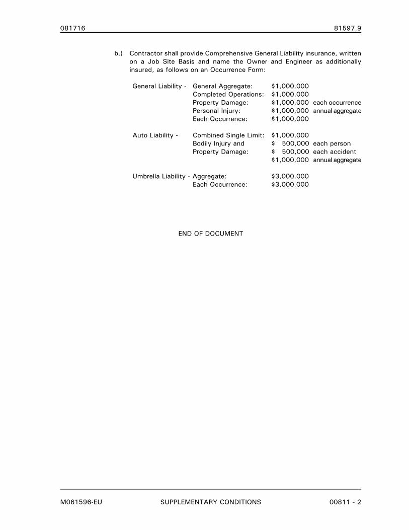
b.) Contractor shall provide Comprehensive General Liability insurance, written
on a Job Site Basis and name the Owner and Engineer as additionally
insured, as follows on an Occurrence Form:
General Liability - General Aggregate: $1,000,000
Completed Operations: $1,000,000
Property Damage: $1,000,000 each occurrence
Personal Injury: $1,000,000 annual aggregate
Each Occurrence: $1,000,000
Auto Liability - Combined Single Limit: $1,000,000
Bodily Injury and $ 500,000 each person
Property Damage: $ 500,000 each accident
$1,000,000 annual aggregate
Umbrella Liability - Aggregate: $3,000,000
Each Occurrence: $3,000,000
END OF DOCUMENT
081716 81597.9
M061596-EU ADDENDA 00900 - 1
DOCUMENT 00900
ADDENDA
1. INTERPRETATIONS - ADDENDA
A. Interpretations and Addenda for questions concerning the meaning or intent of the Contract
Documents and response of these will be made through the issuing of Addenda.
B. All Addenda are incorporated, by reference, into the Contract. Failure of any Bidder or sub-
bidder to receive any addenda shall not relieve the Bidder of any obligation with respect to
his Bid.
C. All Addenda and modifications to the Contract Documents shall be inserted and indexed
numerically in this location behind this page and coordinated as instructed in each
Addendum.
END OF DOCUMENT
081716 81597.9
060100-EU PROJECT COORDINATION 01040 - 1
SECTION 01040
PROJECT COORDINATION
PART 1. GENERAL
1.01 SECTION INCLUDES
A. Coordination
B. Project Representatives and Addresses
1.02 COORDINATION
A. All work, submittals, and testing shall be coordinated with the Work listed in the Contract
Documents to assure efficient progress of the Project Construction.
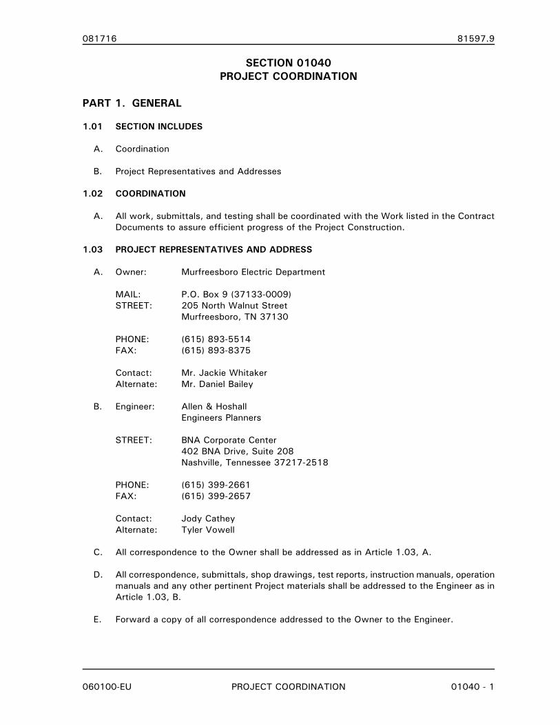
1.03 PROJECT REPRESENTATIVES AND ADDRESS
A. Owner: Murfreesboro Electric Department
MAIL: P.O. Box 9 (37133-0009)
STREET: 205 North Walnut Street
Murfreesboro, TN 37130
PHONE: (615) 893-5514
FAX: (615) 893-8375
Contact: Mr. Jackie Whitaker
Alternate: Mr. Daniel Bailey
B. Engineer: Allen & Hoshall
Engineers Planners
STREET: BNA Corporate Center
402 BNA Drive, Suite 208
Nashville, Tennessee 37217-2518
PHONE: (615) 399-2661
FAX: (615) 399-2657
Contact: Jody Cathey
Alternate: Tyler Vowell
C. All correspondence to the Owner shall be addressed as in Article 1.03, A.
D. All correspondence, submittals, shop drawings, test reports, instruction manuals, operation
manuals and any other pertinent Project materials shall be addressed to the Engineer as in
Article 1.03, B.
E. Forward a copy of all correspondence addressed to the Owner to the Engineer.
081716 81597.9
060100-EU PROJECT COORDINATION 01040 - 2
F. Notify Owner and Engineer of the Primary Project Representative, Alternate Project
Representative, mailing address, package delivery address, phone number (normal working
hours), phone number (after working hours) and fax number.
G. All correspondence, submittals or other items associated with the Contract shall be
identified by the Project Owner and Project name as listed in the Contract Documents.
PART 2. PRODUCTS
(NOT USED)
PART 3. EXECUTION
(NOT USED)
END OF SECTION
081716 81597.9
060100-EU REFERENCE STANDARDS 01090 - 1
SECTION 01090
REFERENCE STANDARDS
PART 1. GENERAL
1.01 SECTION INCLUDES
A. Quality Assurance
B. Schedule of References
1.02 QUALITY ASSURANCE
A. Comply with latest revision of the standard for all equipment, materials and labor, except
when more rigid requirements are specified or are required by applicable codes.
B. Request clarification from Engineer before proceeding, should specified reference standards
conflict with Contract Documents.
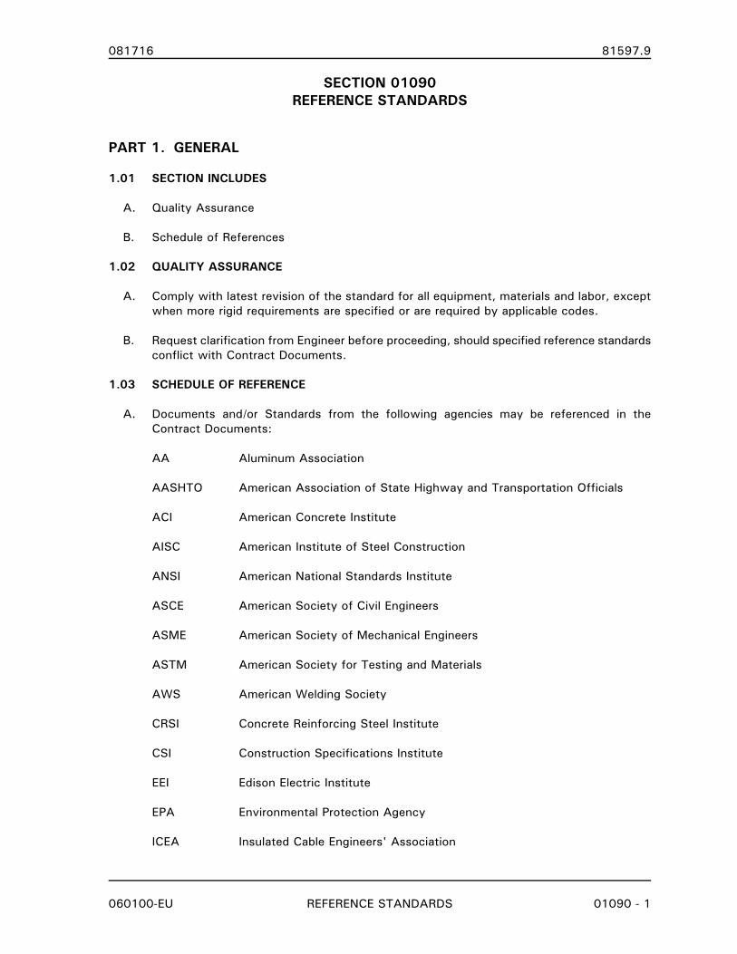
1.03 SCHEDULE OF REFERENCE
A. Documents and/or Standards from the following agencies may be referenced in the
Contract Documents:
AA Aluminum Association
AASHTO American Association of State Highway and Transportation Officials
ACI American Concrete Institute
AISC American Institute of Steel Construction
ANSI American National Standards Institute
ASCE American Society of Civil Engineers
ASME American Society of Mechanical Engineers
ASTM American Society for Testing and Materials
AWS American Welding Society
CRSI Concrete Reinforcing Steel Institute
CSI Construction Specifications Institute
EEI Edison Electric Institute
EPA Environmental Protection Agency
ICEA Insulated Cable Engineers' Association
081716 81597.9
060100-EU REFERENCE STANDARDS 01090 - 2
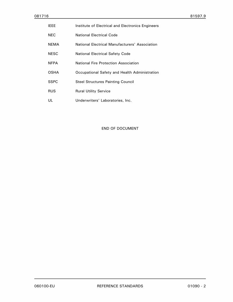
IEEE Institute of Electrical and Electronics Engineers
NEC National Electrical Code
NEMA National Electrical Manufacturers' Association
NESC National Electrical Safety Code
NFPA National Fire Protection Association
OSHA Occupational Safety and Health Administration
SSPC Steel Structures Painting Council
RUS Rural Utility Service
UL Underwriters' Laboratories, Inc.
END OF DOCUMENT
081716 81597.9
M032415-EU SUBMITTALS 01301 - 1
SECTION 01301
SUBMITTALS
PART 1. GENERAL
1.01 SECTION INCLUDES
A. Submittal Procedures
B. Shop Drawings
C. Product Data
D. Manufacturers' Certificates
1.02 RELATED SECTIONS
A. DIVISIONS 0 and 1 - CONTRACT DOCUMENTS, and GENERAL REQUIREMENTS: These
shall apply to all work included in this section.
B. Section 01040 - PROJECT COORDINATION
C. Section 01341 - SHOP DRAWINGS
D. Section 01721 - PROJECT RECORD DOCUMENTS
E. Section 16162 – SUBSTATION CONTROL AND SWTICHGEAR HOUSING
F. Section 16350 – MEDIUM-VOLTAGE METAL-CLAD SWITCHGEAR
G. Section 16632 – CENTRAL NICKEL-CADMIUM BATTERY SYSTEM
1.03 SUBMITTAL PROCEDURES
A. Transmit each submittal with transmittal letter or Engineer accepted form.
B. Submit shop drawings as specified in Section 01341 - SHOP DRAWINGS
C. Identify Owner’s name, project title, pertinent drawing sheet and detail number(s), and
specification section number, as appropriate.
D. Schedule submittals to expedite the project, and deliver to Engineer with copy of
transmittal letter to Owner's representative as identified in Section 01040 - PROJECT
COORDINATION. Coordinate submission of related items.
E. Identify variations from Contract Documents and product or system limitations which may
be detrimental to successful performance of the completed Work.
F. Provide space for Contractor and Engineer review stamps.
G. Revise and resubmit submittals as required, identify all changes made since previous
submittal.
081716 81597.9
M032415-EU SUBMITTALS 01301 - 2
1.04 SUBMITTAL SCHEDULE
A. Provide a submittal schedule indicating review dates and return dates required to maintain
project schedule.
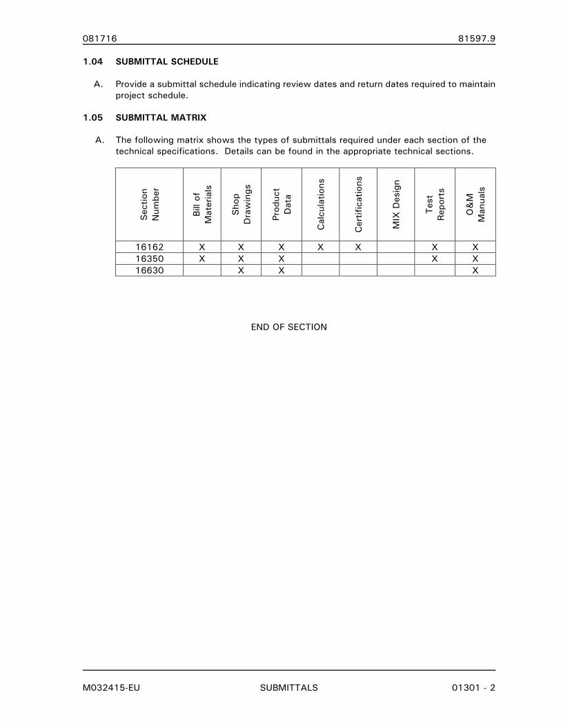
1.05 SUBMITTAL MATRIX
A. The following matrix shows the types of submittals required under each section of the
technical specifications. Details can be found in the appropriate technical sections.
Section
Number
Bill of
Materials
Shop
Drawings
Product
Data
Calculations
Certifications
MIX Design
Test
Reports
O&M
Manuals
16162 X X X X X X X
16350 X X X X X
16630 X X X
END OF SECTION
081716 81597.9
M062912-EU SHOP DRAWINGS 01341 - 1
SECTION 01341
SHOP DRAWINGS
PART 1. GENERAL
1.01 SECTION INCLUDES
A. Shop Drawing submittals
1.02 RELATED SECTIONS
A. DIVISIONS 0 and 1 - CONTRACT DOCUMENTS, and GENERAL REQUIREMENTS: These
shall apply to all work included in this section.
B. Section 01301 - SUBMITTALS
C. Section 01721 - PROJECT RECORD DOCUMENTS
1.03 SHOP DRAWINGS
A. Shop drawings shall include: fabrication, erection, layout, and setting drawings; material
lists; manufacturer's catalog sheets and/or descriptive data for materials and equipment
showing dimensions, performance characteristics, and capacities; wiring and control
diagrams; electrical characteristics, and capacities; and other pertinent information as
required to obtain approval of the items involved.
B. Drawings shall be presented in a clear and thorough manner.
1. Details shall be identified by reference to sheet and detail numbers shown on Contract
Drawings and Specification Sections.
C. Minimum sheet size: 8½" x 11".
D. Maximum sheet size: 22" x 34"
1.04 PRODUCT DATA
A. Preparation:
1. Clearly mark each copy to identify pertinent products or models.
2. Show performance characteristics and capacities.
3. Show dimensions and clearances required.
B. Manufacturer's standard schematic drawings and diagrams:
1. Modify drawings and diagrams to delete information which is not applicable to the
Work.
2. Supplement standard information to provide information specifically applicable to the
Work.
081716 81597.9
M062912-EU SHOP DRAWINGS 01341 - 2
1.05 MATERIALMAN RESPONSIBILITIES
A. Designate in the submittal schedules, the dates for submission and the dates that reviewed
Shop Drawings and product data will be required to maintain delivery schedule.
B. Review Shop Drawings and Product Data prior to submission. Materialman shall allocate
10 business days (excluding holidays) in the project schedule for the Engineer’s initial
review. Additional time may be necessary for resubmissions.
C. Determine and verify:
1. Catalog numbers and similar data
2. Conformance with specifications
D. Coordinate each submittal with requirements of the Work and of Contract Documents.
E. Notify the Engineer in writing (include e-mail), in advance of submission, of any deviations
in the submittals from requirements of the Contract Documents. Materialman requested
deviations may require additional supporting documentation before the Engineer acts on the
request.
F. Begin no fabrication or work which required submittals until return of submittals with
satisfactory review.
1.06 SUBMISSION REQUIREMENTS
A. Make submittals promptly in accordance with approved schedule.
B. Number of submittals required:
1. Shop Drawings: Submit one (1) copy of electronic data files of all drawings prepared
for the project. Electronic data files shall be either a Design Web Format (.DWF) or a
PDF format. Raster based scans (.TIF, .PCX, or .GIF) files of manual drawings are not
acceptable.
2. Product Data: Submit one electronic (1) copy of product data of all items for which
product data is specified in other sections. Electronic data files shall be in a PDF
format.
3. Shop Drawings and Product Data can be provided on a CD-ROM or via e-mail. When
submittal data is delivered via e-mail, it is the Materialman’s responsibility to verify
receipt by the Engineer.
C. Submittals shall contain:
1. Submittal identification number. Submittals shall be numbered consecutively. Re-
submittals shall use the same submittal number with an alphabetic suffix added.
2. The date of submission and the dates of any previous submissions.
3. The Owner’s name, project title and number.
4. Contract identification.
081716 81597.9
M062912-EU SHOP DRAWINGS 01341 - 3
5. Identification of the project, with the specification section number.
6. Relation to adjacent or critical features of the work or materials.
7. Applicable standards, such as ASTM or Federal Specification numbers.
8. Identification of deviations from Contract Documents.
9. Identification of revisions on resubmittals.
10. An 8"x3" blank space for Materialman and Engineer stamps.
1.07 RETURN FOR RESUBMISSION
A. The Engineer will return for resubmission all shop drawings submitted without the above
specified approval and certification which in the Engineers opinion contain numerous
discrepancies, have not been checked, or do not meet the requirements for submission.
1.08 REVIEW OF SUBMITTALS
A. The Engineer will review, mark and date all submitted shop drawings. One (1) electronic set
will be returned to the Materialman. Materialman shall make corrections and changes as
indicated.
B. Resubmit shop drawings as specified above, until satisfactory review has been obtained.
Corrections and/or changes indicated on shop drawings by Engineer/Owner shall not be
considered as an extra work order.
C. After satisfactory "Review" or "Furnish as Corrected" has been obtained for all shop
drawings, a set of shop drawings marked "FOR CONSTRUCTION" shall be furnished to the
Engineer in the format specified in Article 1.06 above. The “FOR CONSTRUCTION”
drawings shall be provided within 21 days of receipt of approval drawings by Materialman.
D. Review of shop drawings by the Engineer will be general only, and such review will not
relieve the Materialman of responsibility for accuracy of such shop drawings, proper fitting,
coordination, construction of work, and furnishing materials required by the Specifications
but not indicated on shop drawings. Review of shop drawings shall not be construed as
approving departures from the Specifications.
1.09 ENGINEER DUTIES
A. Review submittals with reasonable promptness and in accordance with schedule.
B. Affix stamp and initials or signature, and indicate requirements for resubmittal, or
satisfactory review of submittal.
C. Return submittals to Materialman for distribution or for resubmission.
PART 2. PRODUCTS
(NOT USED)
081716 81597.9
M062912-EU SHOP DRAWINGS 01341 - 4
PART 3. EXECUTION
(NOT USED)
END OF SECTION
081716 81597.9
M062912-EU PROJECT RECORD DOCUMENTS 01721 - 1
SECTION 01721
PROJECT RECORD DOCUMENTS
PART 1. GENERAL
1.01 SECTION INCLUDES
A. Final “As-Built” record drawings
B. Factory test results
C. Operation/Maintenance manuals
1.02 RELATED SECTIONS
A. DIVISIONS 0 and 1 - CONTRACT DOCUMENTS, and GENERAL REQUIREMENTS: These
shall apply to all work included in this document.
B. Other requirements affecting Project Record Documents may appear in pertinent other
Sections of these Specifications.
1.03 SUBMITTALS
A. Comply with pertinent provisions of GENERAL CONDITIONS and Section 01301 -
SUBMITTALS.
B. Prior to submitting request for final payment, submit the final Project Record Documents to
the Engineer/Architect for approval.
1.04 MATERIALMAN RESPONSIBILITIES
A. The Materialman shall provide final "As-Built" record drawings of the work with all revisions
in incorporated.
B. The Materialman shall provide factory test results, as applicable, for all material furnished.
C. The Materialman shall provide complete operation and maintenance manuals for all
equipment furnished.
PART 2. PRODUCTS
(NOT USED)
081716 81597.9
M062912-EU PROJECT RECORD DOCUMENTS 01721 - 2
PART 3. EXECUTION
3.01 FINAL DRAWINGS
A. At completion of project, the Materialman shall incorporate all revisions into the shop
drawings to provide a complete set of final drawings. The drawings shall be marked as
"Final-As Constructed".
B. One (1) copy of electronic data files of all drawings prepared for the project. Format shall
be AutoCAD 2000 or later, vector based (.DWG or .DXF) files. Scanned, raster based
(.TIF, .PCX, or .GIF) files of manual drawings are not acceptable. Media shall be IBM CD-
ROM or via e-mail.
3.02 FACTORY TEST RESULTS
A. The Materialman shall provide, as a minimum, results for all routine or production tests
required by the industry standards referenced in the technical sections.
B. The Materialman shall also provide results for any non-routine tests specified in the
technical sections.
C. When required in the technical sections, required test results shall be forwarded to the
Engineer prior to shipping.
D. Engineer shall have two (2) weeks to review factory test results before shipping.
3.03 OPERATION AND MAINTENANCE MANUALS
A. The Materialman shall provide three (3) complete sets of Operations, Maintenance and
Instruction Manuals covering all equipment furnished for the project.
B. Contents of Manuals
1. Table of Contents and index tabs.
2. Description of the equipment.
3. Operating instructions.
4. Installation instructions including rigging and lifting details.
5. Maintenance instructions.
6. Instruction manuals for installation, operation and maintenance of each accessory
device, including oil filling procedures.
7. Assembly drawings.
8. Parts list.
9. List of recommended spare parts.
081716 81597.9
M062912-EU PROJECT RECORD DOCUMENTS 01721 - 3
10. List of maintenance tools furnished with the equipment.
11. Nameplate information and shop order numbers for each item of equipment and component part.
12. Final As-Constructed shop drawings.
13. Photographs (if required in specifications).
14. Certified factory test results.
C. Format
1. All Manuals shall be bound in a three ring binder of suitable size (maximum 2") for the
material to be inserted.
2. Binders shall be white in color with clear jacket for the insertion of printed cover and
edge identification sheets.
3. Instruction manuals for microprocessor based relays shall be provided in the
manufacturers’ original binding or in a separate three-ring binder produced by the
Materialman with dividers identical to the relay manufacturers’ manual.
4. All information bound shall be 8½" x 11" or accordion folded to this size.
5. Page dividers with plastic reinforced holes and tabs shall be used to organize
Operations and Maintenance Manuals.
6. Binder cover and edge inserts shall contain Owner’s name, project title, date and
subject matter of the manual.
D. Organization
1. Table of Contents shall list all information contained.
2. Contact information for all major equipment suppliers, Materialman, and
subcontractors.
3. Organize manual by equipment item. Contents as specified above.
3.04 FINAL SUBMITTAL
A. All Record Documents, including final drawings and Operation, Maintenance and Instruction
Manuals shall be submitted to Engineer prior to submitting final payment request.
3.05 CHANGES SUBSEQUENT TO ACCEPTANCE
A. The Materialman has no responsibility for recording changes in the Work subsequent to
Final Completion, except for changes resulting from work performed under Warranty.
END OF SECTION
081716 81597.9
M041114-EU SUBSTATION CONTROL AND SWITCHGEAR HOUSING 16162 - 1
SECTION 16162
SUBSTATION CONTROL AND SWITCHGEAR HOUSING
PART 1. GENERAL
1.01 SECTION INCLUDES
A. Substation Control and Switchgear Housing (CSH) for protective relaying, metering, metal-
clad switchgear (when specified), and all auxiliary equipment as indicated on the contract
drawings.
B. The Substation Control and Switchgear Housing Contractor shall serve as the single point
of responsibility for field service as well as warranty for all component systems installed
within the CSH. The Contractor shall provide all interconnecting wiring between component
systems mounted within the CSH and shall furnish functional testing of these systems. The
Owner is responsible for all cable connections to equipment located external to the CSH.
1.02 DEFINITIONS
A. Contractor: The entity responsible for the manufacture, shipping, and installation of the
specified Substation Control and Switchgear Housing.
B. Project Construction Contractor: The entity responsible for the connection of all external
devices, power system equipment, AC power supply, and associated facilities to the
Substation Control and Switchgear Housing.
1.03 PRODUCTS SUPPLIED BUT NOT INSTALLED UNDER THIS SECTION
A. None
1.04 PRODUCTS INSTALLED BUT NOT SUPPLIED UNDER THIS SECTION
A. None
B. The Contractor shall install Owner furnished TWACS Automatic Meter Reading equipment
as shown in the Contract Drawings. The Contractor will be responsible for Equipment
installation in the Control House and wiring from the CRU (Control and Receiving Unit) to
the IPU (Inbound Pickup Unit) as shown on the Contract Drawings. Cables from the OMU
(Outbound Modulation Unit) to the CRU will be installed by the Owner. The equipment will
be shipped by the OWNER to the Contractor for installation.
C. The TVA Underfrequency Panel Insert is installed in the relay panels and the installation is
specified in Section 16345 SUBSTATION RELAY/CONTROL PANEL(S) and ASSOCIATED
EQUIPMENT.
1.05 RELATED SECTIONS
A. DIVISIONS 0 and 1 - PROPOSAL DOCUMENTS, CONTRACT DOCUMENTS AND GENERAL
REQUIREMENTS: These shall apply to all work included in this section.
B. Section 16350 - MV METAL-CLAD SWITCHGEAR
081716 81597.9
M041114-EU SUBSTATION CONTROL AND SWITCHGEAR HOUSING 16162 - 2
C. Section 16350D - MV METAL-CLAD SWITCHGEAR DATA SHEET
D. Section 16632 – CENTRAL NICKEL CADMIUM BATTERY SYSTEM
1.06 REFERENCE STANDARDS
A. The latest revision of Published Specifications, standards, tests, or recommended methods
of trades, industry, or governmental organizations apply to work in this section where cited
in Section 01090 - REFERENCE STANDARDS and in the listing below.
1. International Building Code (IBC)
2. International Mechanical Code (IMC)
3. American National Standards Institute (ANSI)
4. American Society of Civil Engineers (ASCE)
5. National Electric Manufacturers Association (NEMA)
6. American Society of Heating, Refrigerating and Air-Conditioning Engineers (ASHREA)
1.07 SERVICE CONDITIONS
A. The Control and Switchgear Housing will be for housing relay/control panels, metal-clad
switchgear (when specified), and associated equipment.
B. The Control and Switchgear Housing will be installed outdoors at an elevation of less than
3,000 ft. above mean sea level.
C. Foundation type and general design (Owner furnished) for the Control and Switchgear
Housing will be as shown on the Contract Drawings.
1.08 UNUSUAL SERVICE CONDITIONS
A. None
1.09 DESIGN REQUIREMENTS
A. The equipment requirements and specifications for the Control and Switchgear Housing are
as shown in these Contract Documents and Drawings.
B. Contractor shall be responsible for the detail design of the Control and Switchgear Housing,
shop drawings and addition of pin numbers of relay/control devices, terminal blocks, and
associated equipment to the Engineer provided schematics/elementary diagrams. The
Contractor is also responsible for modifying the schematic/elementary diagrams as-built and
shipped. This includes design changes and/or revisions due to testing of the CSH. This
information shall be added to a separate layer on the Engineer furnished AutoCAD
drawings.
C. Contractor shall be responsible for the detail design of the physical point-to-point wiring of
the CSH equipment.
D. Contractor shall be responsible for construction detail and shop drawings required for
fabrication of the CSH.
081716 81597.9
M041114-EU SUBSTATION CONTROL AND SWITCHGEAR HOUSING 16162 - 3
1.10 SUBMITTALS
A. General
1. Shop drawings shall be submitted for approval in accordance with Section 01301-
SUBMITTALS and Section 01341- SHOP DRAWINGS as listed in the TABLE OF
CONTENTS of these Contract Documents.
2. Submittal information shall include dimension data and other information in the
English foot/pound/inch system of units.
B. Proposal/Bidding/Quotation Submittals
1. Bill of Material
2. Enclosure Outline & Details
3. Installed weight
4. Proposed shipping weight, size, and shipping split information
C. Shop Drawings
1. Bill of Material
2. Enclosure Outline & Details
3. Installed weight
4. Shipping size, shipping split information
5. Enclosure Anchorage Design
a. Foundation reactions for the specified loadings
b. Anchor rod specifications
6. Enclosure Schematics & Wiring Diagrams (with shipping split information)
7. HVAC Calculations
D. Certifications
1. Certification Letter/Statement of certification of compliance with the latest revision of
the International Building Code (IBC) seismic requirements shall be submitted with
shop drawings for review. Certificate of Compliance shall be sealed by a sealed by a
Professional Engineer licensed by the state where the Control and Switchgear Housing
is to be located. This certificate is required by Federal Law 7 CFR1792, Subpart C.
2. Certification sealed by a Professional Engineer verifying that proposed structure
meets the loading requirements and codes listed in this specification.
E. Contract Closeout Documents
1. Closeout Submittals shall be provided before shipment of the CSH in accordance
with Section 01721- PROJECT RECORD DOCUMENTS as listed in the TABLE OF
CONTENTS of these Contract Documents.
2. Closeout Submittals shall include, but not limited to:
a. Final Drawings (As-Built, Record Drawings)
b. Manuals
c. Recommended Spare Parts List
d. Certified Test Reports
081716 81597.9
M041114-EU SUBSTATION CONTROL AND SWITCHGEAR HOUSING 16162 - 4
1.11 DELIVERY, STORAGE, AND HANDLING
A. The Control and Switchgear Housing shall be shipped as one unit when possible. Should
transportation require shipping splits, each open area shall be sealed with temporary 2 inch
(nominal) thick wooden framing and plywood cover for protection during transportation and
storage at the job site. Seams in the temporary cover shall be liberally caulked on the
exterior.
B. Transportation of Control and Switchgear Housing shall be in compliance with all state and
federal regulations with respect to highway permits, battery systems, and safety
requirements. Contractor is responsible for all necessary permits.
1.12 WARRANTY
A. All materials and equipment supplied under this specification shall be warranted as outlined
in Document 00711 - GENERAL CONDITIONS.
B. Items to include in statement of warranty:
1. Assignments of warranties of any systems, materials or components that exceed
the one (1) year shelter warranty period
2. Instruction on activating warranty
3. Instructions on submitting claims for service under warranty
PART 2. PRODUCT
2.01 MANUFACTURERS
A. Central Electric
B. Powercon, Inc.
2.02 MATERIALS
A. General
1. Enclosure NEMA classification: NEMA 3R
2. The Contractor shall check the dimensions of the proposed equipment for required
electrical and safety clearances front and back of the equipment within the CSH,
space for interconnection, and confirm that the overall shipping dimensions meet all
interstate shipping requirements to transport the CSH from the factory to the final
destination.
3. Nominal dimensions of the CSH shall be as indicated on the Contract Drawings. These
dimensions are considered as guideline dimensions. Actual dimensions will be
determined by the physical size of the electrical components proposed. Construction
of CSH, installation of equipment, and foundation anchor methods shall withstand the
vertical and horizontal forces associated with the wind, seismic, and operational
loads.
081716 81597.9
M041114-EU SUBSTATION CONTROL AND SWITCHGEAR HOUSING 16162 - 5
B. Structural Requirements
1. Design Loads Definitions:
a. Dead Load: The Control and Switchgear Housing “shell” and all installed
equipment including relay panels, breakers, cubicles, battery systems, HVAC, or
any other equipment installed within the CSH by the Contractor.
b. Live Load: Includes all loads associated with personnel, maintenance activities,
test equipment, and equipment to be installed within the CSH by the OWNER.
Live Load specification applies only to accessible floor areas of the CSH.
c. Floor Concentrated Load: This is a concentrated load applied within any 6 inch
by 6 inch area within the accessible floor boundaries of the CSH.
d. Cable Tray Live Load: Loading, per linear foot of the cable tray that may be
applied by the Owner. This load is transferred to the CSH structure and/or roof.
e. Accessible Floor Area: Floor space that is accessible for personnel, maintenance
activities, and installation of equipment by the OWNER. Floor space occupied by
metal-clad switchgear cubicles, for example, is NOT accessible under this
definition.
2. Design Loads:
a. Floor live load (uniform per ASCE 7)
i) On foundation 125 psf.
ii) During lifting and transport 125 psf.
b. Floor Concentrated Load: 500 lbs.
c. Roof live load (uniform per ASCE 7) 35 psf.
d. Cable Tray Live Load: 75 pounds per Linear Foot.
e. Wind load (per ASCE 7) 110 mph, Exposure C
f. Seismic Loading:
i) Structure, equipment mounting for listed systems, and structure
anchorage to the foundation shall meet the seismic requirements of the
latest revision of the International Building Code (IBC).
Occupancy Category: I
Maximum Considered Earthquake Ground Motion of 0.2 second
Spectral Response Acceleration
SS = 25.8
Maximum Considered Earthquake Ground Motion of 1.0 second
Spectral Response Acceleration
S1 = 13.0
081716 81597.9
M041114-EU SUBSTATION CONTROL AND SWITCHGEAR HOUSING 16162 - 6
Spectral response coefficients:
SMS: 0.41
SM1: 0.30
SDS: 0.28
SD1: 0.20
Site Class: D
Importance Factors:
Structure 1.5
Structure anchorage 2.0
Relay/Control Panels 1.5
Battery and Charger System 1.5
All other electrical and mechanical systems 1.0
3. Anchorage to foundation:
a. The Owner will furnish monolithic concrete foundation, or as shown on the
Contract Drawings.
b. The Contractor shall provide the anchorage design required to anchor the CSH to
the specified Owner furnished foundation to meet the wind, seismic, and
operational design loading. Design shall incorporate anchor rod attachment –
welded designs are not acceptable.
c. CSH will be placed on the top of concrete. Leveling nuts will not be used.
d. Anchorage design shall solidly anchor CSH to the foundation to eliminate
horizontal and vertical movement. Designs that control horizontal movement only
are not acceptable.
e. The Contractor shall supply and identify all attachment points on the CSH and all
shims, tie down materials, clamping plates, and all associated hardware required
by the Contractor’s anchorage design. Contractor shall identify anchor rod size
and quantity required to meet design requirements.
i) Anchor Rods and anchor rod installation shall be provided by the Owner.
Installation will be either cast-in-place/embedded in concrete or epoxy
installation with the Hilti Epoxy system or approved equal
ii) Anchor Rods will be manufactured anchor rods or deformed rebar (ASTM
A615). Cast-in-place/embedded anchor rods will be threaded with nut
and washer. Anchor rods for epoxy will be suitable for the purpose.
Anchor Rod steel will be ASTM A36, F1554, or A307 with an ultimate
tension of less than 140,000 ksi or yield tension of less than 94,250
ksi.
C. Structural Components – Steel Construction
1. Wall panels, roof panels, and equipment access doors shall be formed in an
interlocking, self-framing design. All permanent structural primary and secondary
081716 81597.9
M041114-EU SUBSTATION CONTROL AND SWITCHGEAR HOUSING 16162 - 7
members shall consist of non-combustible materials Use of wood or other materials,
which support combustion, shall not be allowed as permanent members.
2. Base members shall be ASTM A36 channel, wide flange and/or angle sections forming
a rigid square and level foundation for the enclosure, and sized to meet or exceed the
static and dynamic loading requirements. Removable lifting lugs are to be supplied for
each shipping split, placed in a position to provide uniform lifting load at each lifting
lug location. The base shall have adequate strength so that when the enclosure is
lifted at the lifting points there will be a deflection no greater than 1/360th of the
unsupported span between and on either side of each lifting point.
3. The floor shall be constructed of 1/4 inch minimum, steel floor welded to the base
framework. Adequate stiffening members to support the specified load with a
deflection of no greater than 1/360th of the distance between the floor stiffener
members, when the CSH is in the normal operating position.
4. All exterior wall panels shall be fabricated using 11 gauge galvanized steel conforming
to ASTM-A569, and be gasketed and bolted together on the inside of the enclosure.
All wall panels are to be provided with stiffeners and adequate flanges to support roof
loads, wind loads, and equipment hanging from such panels.
5. Interior walls shall be 14-gauge minimum, galvanized sheet steel firmly attached to
interlocking ribs of exterior wall panels along all vertical seams. Each interior wall
panel shall be formed to receive adjacent panels at each splice. Interior panels shall be
designed to support all equipment mounted on wall panels.
6. The roof shall be supported by roof trusses bolted to the underside of the roof panels
and to adjacent wall panels. All trusses are to be fabricated of 11 gauge galvanized
steel (ASTM-A569) and are to be designed to support the specified roof loading plus
loads due to all other equipment that may hang from the roof (lights, cable trays, etc.)
or that may be mounted on the roof (bus duct, exhaust fans, hvac units, etc.). Roof
panels shall be 11 gauge galvanized steel (ASTM-A569) and bolted to adjacent roof
panels and bolted to the roof trusses and wall panels. Adequate stiffening must be
provided to support all loads specified. All external bolted seams are to be gasketed,
caulked, and completely covered by roof caps.
7. Ceiling shall be 16-gauge minimum galvanized sheet steel formed to create a tightly
interlocking panel design. The used of a drop ceiling of non-metallic materials is not
acceptable.
D. Electrical Requirements:
1. General
a. Electrical system design and material shall be in accordance with the Contract
Drawings and the NEC.
b. General Interior Lighting - 75 foot candles, 3 feet above floor.
c. Alarms and controls for CSH Systems (Charger, ventilation, door, etc. alarms)
shall be wired to terminal blocks located within the control panels or cubicles,
logically grouped for Owner’s use and connection to Owner supplied
communications, except as may be indicated on the Contract Drawings.
081716 81597.9
M041114-EU SUBSTATION CONTROL AND SWITCHGEAR HOUSING 16162 - 8
d. Alarms shall include (as applicable or as shown on Contract Drawings):
i) Battery Charger operation
ii) Battery Room ventilation equipment failure
iii) Entrance door(s)
iv) Smoke/fire detection
v) Low (50°F) and high (95°F) temperature within CSH
2. Wiring of all AC and DC power shall be RHW, RHW-2, or other non-PVC insulated,
NEC Code compliant, 600 volt insulation, 12 AWG minimum, or as shown on the
Contract Drawings.
a. Wiring between cubicles or panels and separately installed equipment cabinets
such as SCADA and AMR cabinets shall use TC cables as indicated below.
Conductors shall be AWG No. 14.
b. Conductors used as AC and DC “supply bus” for inter-panel AC and DC supply;
and conductors between the relay/control panels and the AC and DC breaker
panels shall be AWG No. 10, minimum. Conductor color code shall meet
National Electric Code requirements.
3. Tray Cables
a. When the use of multi-conductor cables is deemed appropriate for the function
by the Contractor, type TC cable shall be used.
i) Cable conductor size shall be based on function, or as shown on Contract
Drawings.
ii) Control and low voltage power cable insulation shall be Ethylene-Propylene
Rubber (EPR) rated for 90°C/75°C wet conditions. Insulation shall be rated
for 600 Volts AC, 250 Volts DC. Polyethylene jacket shall be provided for
single conductor and multiple conductor cable.
iii) Circuits using single conductors or multiple conductor cables shall be
identified in accordance with ICEA/NEMA Method 1. Color sequence E-1
shall be used for AC power circuits. Color sequence E-2 shall be used for all
DC power, control, and instrument transformer secondary circuits. See Table
below:
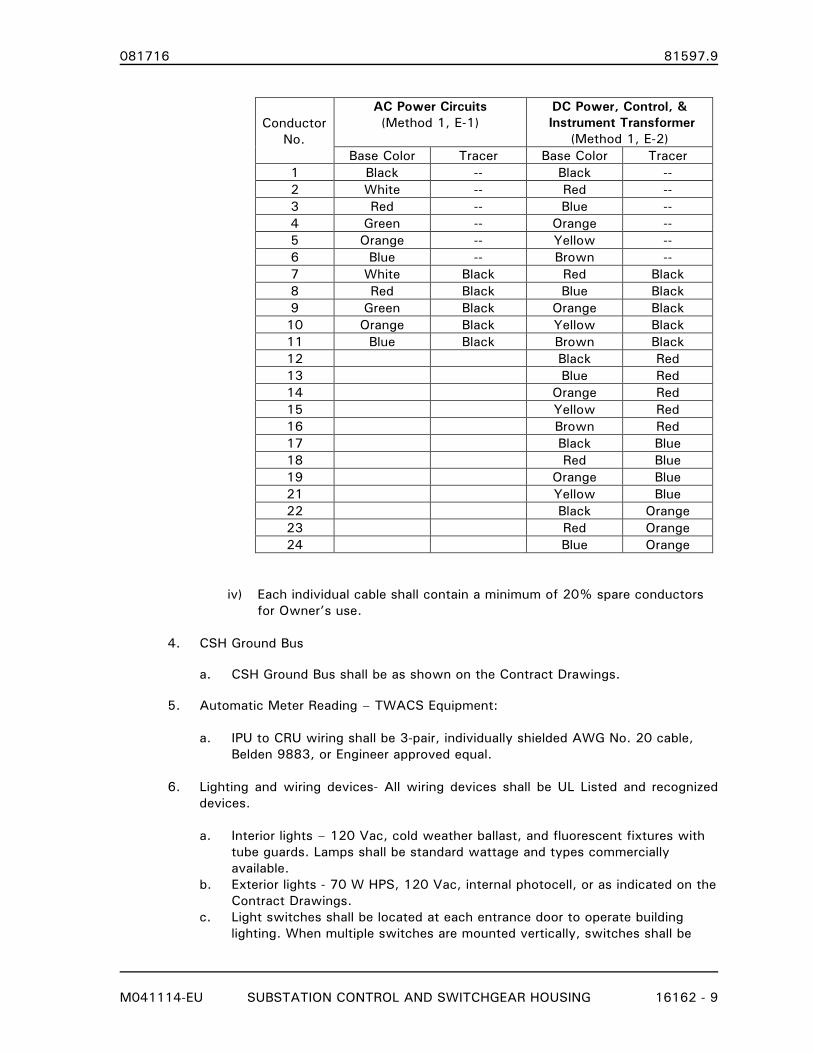
081716 81597.9
M041114-EU SUBSTATION CONTROL AND SWITCHGEAR HOUSING 16162 - 9
Conductor
No.
AC Power Circuits
(Method 1, E-1)
DC Power, Control, &
Instrument Transformer
(Method 1, E-2)
Base Color Tracer Base Color Tracer
1 Black -- Black --
2 White -- Red --
3 Red -- Blue --
4 Green -- Orange --
5 Orange -- Yellow --
6 Blue -- Brown --
7 White Black Red Black
8 Red Black Blue Black
9 Green Black Orange Black
10 Orange Black Yellow Black
11 Blue Black Brown Black
12 Black Red
13 Blue Red
14 Orange Red
15 Yellow Red
16 Brown Red
17 Black Blue
18 Red Blue
19 Orange Blue
21 Yellow Blue
22 Black Orange
23 Red Orange
24 Blue Orange
iv) Each individual cable shall contain a minimum of 20% spare conductors
for Owner’s use.
4. CSH Ground Bus
a. CSH Ground Bus shall be as shown on the Contract Drawings.
5. Automatic Meter Reading – TWACS Equipment:
a. IPU to CRU wiring shall be 3-pair, individually shielded AWG No. 20 cable,
Belden 9883, or Engineer approved equal.
6. Lighting and wiring devices- All wiring devices shall be UL Listed and recognized
devices.
a. Interior lights – 120 Vac, cold weather ballast, and fluorescent fixtures with
tube guards. Lamps shall be standard wattage and types commercially
available.
b. Exterior lights - 70 W HPS, 120 Vac, internal photocell, or as indicated on the
Contract Drawings.
c. Light switches shall be located at each entrance door to operate building
lighting. When multiple switches are mounted vertically, switches shall be
081716 81597.9
M041114-EU SUBSTATION CONTROL AND SWITCHGEAR HOUSING 16162 - 10
located as follows: Bottom switch- normal CSH lighting, Middle switch-
exterior lighting, Top switch- CSH emergency lighting.
d. Duplex receptacle(s) - specification grade 20 A, 125 Vac, GFCI duplex
receptacle(s) shall be provided near entrance door(s) and can also be located
on interior walls of the enclosure as shown on the Contract Drawings.
e. Exterior receptacle(s) shall be equipped with weatherproof cover.
f. Battery Room (when specified) Electrical Equipment shall be suitable for the
application and in accordance with NEC, NESC, and other applicable codes.
No wiring devices shall be located within the battery room unless rated for
the purpose and application.
7. Emergency Lighting
a. Emergency light – Dual-head, 100 W, 12 Vdc, self-contained, continuously
charged, 120 Vac supply as shown on the Contract Drawings.
8. AC Panel and Control Power/Station Service Transfer Switch.
a. AC Distribution Breaker Panel, General Electric 225 Amp, 120/240 Vac, 1Ø, 3W,
22,000 AIC, surface mount, Type AQ Panelboard with cover. Type THQD and
Type THHQB safety breakers rated to match panel AIC. Main and Branch
breakers sized as shown on the Contract Drawings.
b. Secondary Surge Arrester, Square D, SDSA1175 Series 001. Secondary surge
arrester shall be externally attached to AC Distribution Breaker Panel in a manner
to allow obvious visual inspection of Operational LED. Connect for 120/240 Vac
operation as shown on the Contract Drawings.
c. Automatic Transfer Switch, 200 amp, 120/240 Vac, 3 wire, 2-Pole Open
Transition, NEMA 1 enclosure with controls for automatic transfer between
Primary and Alternate control power/station service (Utility-Utility Operation).
Primary and Alternate sources shall be selectable. Controls shall allow
adjustment of transfer timing from Primary to Alternate and back to Primary
source. Auxiliary switch contacts for status of ATS position shall be provided.
Auxiliary switch contacts shall be wired to SCADA System RTU, when
applicable. Primary and Alternate Sources shall be the specified CPT/Station
Service Transformers or as indicated on the Contract Drawings.
Service Entrance Rated ATS:
Eaton, breaker based transfer switch, ATVIKDB20225WSU, rated for service
entrance equipment, or Engineer approved equal.
9. DC System
a. DC Distribution Panel, General Electric Type AE Panelboard, 225 Amp main
breaker, 250 Vdc, 2W, with copper bus bars, surface mount with cover door.
Main Breaker, Type TFJ and Type TEY Branch breakers. Breakers sizes as shown
on the Contract Drawings.
b. DC transfer switch shall be a Cutler Hammer DC Safety Switch, part number
DT224UGK. Signage shall include color code description.
081716 81597.9
M041114-EU SUBSTATION CONTROL AND SWITCHGEAR HOUSING 16162 - 11
c. DC Disconnect Switch, 250 volt, 100 amp, non-fusible, manual operated, for
the connection of an external/emergency/testing battery system.
d. Station Battery System Conductors. Conductors connecting station battery
to DC load center panel and charger shall be sized as shown below:
i) Conductor size:
Battery Charger Output to DC Load Center (branch breaker):
CHARGER DC CONDUCTOR
RATED OUTPUT SIZE
6 Amps 10 AWG
15 10
25 8
50 4
Station Battery to DC Load Center:
BATTERY
AMPERE HOUR CONDUCTOR
CAPACITY (8HR) SIZE
Up to 100 4 AWG
101 to 200 1/0
201 to 300 2/0
ii) Positive and Negative conductors connecting the station battery to the
DC load center panel shall be contained in separate non-metallic tubing.
iii) Conductors shall be color coded:
Positive RED
Negative BLACK
iv) Signage shall include color code description.
E. Mechanical Requirements
1. Design Loads
a. Ambient temperatures:
i) Summer: 104 °F
ii) Winter: -10 °F
b. Interior design temperature:
i) Summer: 80 °F at maximum ambient
ii) Winter: 60 °F at minimum ambient
c. Ambient Relative Humidity: 5% to 95%
081716 81597.9
M041114-EU SUBSTATION CONTROL AND SWITCHGEAR HOUSING 16162 - 12
2. Energy Conservation:
a. CSH shall be design to meet the environmental requirements specified in an
energy efficient manner in accordance with ASHRAE Energy Standard 90.1.
b. Walls, ceiling, and floor shall be insulated to meet energy conservative standards
and yield total shelter U0 factor less than 0.09 btu/hr/ft2/°F when calculated per
ASHRAE 90.1.
c. SEER rating for HVAC equipment: 10 minimum
3. HVAC calculations shall be submitted with approval drawings showing required sizing
for ventilation, heating/air conditioning loads, indicating ambient infiltration and
internal equipment heat losses used as design parameters.
4. HVAC Equipment:
a. Heater - with external thermostat shall be installed and tested at the factory and
may be removed from the wall for shipping.
b. Refrigerant for air conditioner equipment shall be R-410A.
c. HVAC Units shall be standard design wall-mounted package units, removable for
shipping or replacement. Package units requiring roof mounting, separate
foundations or ductwork to connect to CSH are not acceptable.
d. Ductwork contained within the CSH to provide the specified temperatures and
equal heating/cooling within the structure is acceptable. When ductwork is
required by the Contractor’s HVAC design, it shall be incorporated into the
overall design such that the installed ductwork will not interfere with any
installation or maintenance activities of the CSH or equipment contained within
the CSH.
F. Station Battery Enclosure / Room:
1. Battery System shall be as shown on the Contract Drawings.
a. Battery shall be separated from the relay and control sections of the CSH by
enclosure or separate battery room as shown on the Contract Drawings.
b. Battery rack shall be connected to the CSH floor construction in a manner to
meet the seismic requirements as stated in the Contract Documents.
c. Finished floor coating shall be Ni-Cd electrolyte resistant.
d. Spill containment shall be provided within the battery rack design.
e. Battery System Ventilation Fan shall be controlled by timer and HOA switch.
f. Battery System Ventilation Fan shall provide a minimum of 3 air changes per
day.
g. Ventilation equipment shall be suitable for the application and provide alarm
contacts for monitoring operation (notification of failure).
h. Ventilation air source shall be:
i) Filtered
ii) The environmentally controlled CSH interior
081716 81597.9
M041114-EU SUBSTATION CONTROL AND SWITCHGEAR HOUSING 16162 - 13
i. Battery System Ventilation Fan exhaust shall be equipped with shutters, rain
guard, and screen.
G. Fire Protection System
1. Provide a hand held, wall mounted U.L. rated fire extinguisher near each of the main
doors. Fire extinguisher - 20A:80B:C 20 LB
2. Smoke/fire detection system
a. Provide smoke detectors with independent relay contacts for shutdown of all
ventilation systems and system monitoring
b. Smoke detectors shall be operated from station battery system or 120 Vac with
continuously charged separate battery backup.
2.03 ACCESSORIES
A. Doors. The CSH shall be equipped with personnel/equipment entrance doors as indicated
on the specification drawings to allow for the removal of equipment. Doors are to be
fabricated from 11-gauge steel (ASTM-A569) and shall be equipped with panic hardware to
allow exit during emergency conditions. All entrance doors shall be two wall construction
with thermal insulation, 11 gauge exteriors, 16 gauge interiors, and gasketed with
watertight seals. Hydraulic door closures shall be provided on the two main entrance
doors. All doors shall be equipped with padlocking provisions and wire reinforced single
pane window. When specified, double doors shall have one active and one inactive leaf to
accommodate entry or exit of large equipment.
B. Equipment/cable termination access doors, as specified, shall be 11 gauge minimum
equipped with stainless steel continuous hinge, stainless steel pad lockable vault handle, 3-
point latching system, full gasketing and drip shield and hold open device. When insulation
is specified, doors shall be equipped with sheet metal interior for insulation protection.
Design shall meet temperature requirements for Metal-Clad Switchgear. Doors shall be
equipped with the following:
1. "DANGER HIGH VOLTAGE" sign
2. Stamped louvers with filter and screen
C. Floor cutouts, if required, for cable entrance and exit below installed equipment shall be
covered with 11 gauge galvanized steel cover plates with gaskets.
D. Cable Tray system shall be provided as indicated on the Contract Drawings. Factory made
TEEs and other fittings shall be used for changes in direction and connection to other
sections of the cable tray system.
E. Enclosure Ground Pads: Enclosures constructed with steel bases shall be equipped with
corrosion resistant NEMA 2-hole pads for grounding of the enclosure and connection to the
CSH Ground Bus.
F. Signage
1. All interior and exterior panels, panel boards, cabinets, switches, ‘connector’ plugs
(generator, spare battery, etc.), and other control equipment and devices shall be
identified with nameplates fabricated from black phenolic with white core. Nameplates
081716 81597.9
M041114-EU SUBSTATION CONTROL AND SWITCHGEAR HOUSING 16162 - 14
shall be attached to the panels with screws suitable for the application or as approved
by the Engineer. Lettering shall be 1/4 inch minimum.
2. Entrance doors shall be equipment with “Caution” – “Control and Battery Systems”
signs in accordance with ANSI Z535.
3. Safety signs inside and outside of the Battery Room, or in the vicinity of the Battery
Enclosure/Area prohibiting smoking, sparks, or flame shall be provided in accordance
with ANSI Z535 and NESC Section 146.
G. Safety Equipment: Gloves, face shield, and apron approved for use with Lead Acid and/or
Ni-Cd Battery System maintenance shall be provided.
H. Eye wash station provided and located in accordance with ANSI Z358.1-2004 or as shown
on the Contract Drawings. When heater jacket is specified, the appropriate power
supply/receptacle shall be provided.
1. Wall-mounted, self-contained, gravity fed. Drainage shall be provided external to
the CSH.
I. NONE
PART 3. EXECUTION
3.01 FABRICATION APPLICABLE TO CONCRETE OR STEEL DESIGN
A. CSH Ground Bus:
1. A copper CSH Ground Bus shall be installed as indicated on the Contract Drawings.
2. CSH Ground Bus, when specified to be located within the cable tray/ladder system
shall be soft drawn copper conductor of the size indicated on the Contract Drawings.
Conductor shall have green insulation or be marked with green tape at 24 inch
intervals along the length of the conductor.
3. CSH Ground Bus, when specified to be located external to the cable tray/ladder
system (e.g. the perimeter of the interior walls) shall be flat copper bar a minimum of
3/16” x 2” on appropriate standoff assemblies. Ground Bus shall be routed over doors
and other similar openings with flat bar. Copper conductor connected to the flat bar to
go “under”, over, or around doors and similar openings is not acceptable.
4. Ground busses for relay/control panels and metal-clad switchgear cubicles shall be
established as per the appropriate specification section.
5. All grounding conductor connections to the CSH Ground Bus shall be color coded with
green insulation.
6. All electrical equipment shall be connected to the CSH ground bus.
7. Telephone Board (when specified) Ground Block shall be connected to the CSH ground
bus with a No.10 AWG minimum, copper grounding conductor.
081716 81597.9
M041114-EU SUBSTATION CONTROL AND SWITCHGEAR HOUSING 16162 - 15
B. All conductors for AC and DC circuits shall be sized and be color coded in accordance with
all applicable codes as listed in Article 1.06 - REFERENCE STANDARDS unless otherwise
noted in these specifications or Contract Documents.
C. All CSH wiring shall be run in exposed 1/2 inch EMT minimum or appropriately sized
wireways. Wireways shall be sized to allow space for future Owner installed wiring. All
utilities shall be functionally tested prior to completion.
D. All wiring between the switchgear cubicles or associated equipment and Owner Furnished
Equipment such as SCADA RTU, Automatic Meter Reading, and similar equipment to be
installed in the CSH shall be Type TC cables, or as specified in Part 2 Products, routed
through appropriate enclosed wireways or cable trays. Conductors shall be sequentially
numbered as “spare” with a “to-from” format.
E. Terminal blocks and/or lug strips utilized for AC or DC supply buses shall be suitable for the
required conductor sizes.
F. All circuits for connection to devices external to the CSH enclosure shall be terminated on
600 volt, 30 ampere, twelve point terminal blocks with washer head screws suitable for
use with 12 AWG size ring type non-insulated conductor terminals.
G. Control cable/conductor wireways shall be sized to accommodate the Contractor’s and or
Owners’ relay panel design requirements and shall provide an additional space of 25% for
the Owner’s use.
H. Removable covers/raceways shall be provided for cables between floor cable entrances and
all AC & DC panels, transfer switches, raceways, and all other similar devices and fixtures
as illustrated in the Contract Drawings.
I. Cable entrances into all AC & DC panels, transfer switches, raceways, and all other similar
devices, cabinets and fixtures shall be provided for the installation of Owner’s cables. Cable
entrances shall be sized to accommodate anticipated cables and utilize grommets or other
similar means to protect cables.
J. Control cable entrances (cables from external power system equipment) shall be
consolidated in a reasonable and logical manner to aid in the relay panel installation.
K. Folding tabletops, when indicated on the Contract Drawings shall be furnished with
appropriate latches to secure the top in the folded position.
L. Vermin control. Enclosure shall be designed to prevent the entrance of mice and other
rodents. Design features may include sealers, gaskets, and screens.
3.02 FABRICATION APPLICABLE TO STEEL DESIGN
A. The outdoor equipment enclosure shall be fully assembled, inspected, and tested at the
factory prior to shipment. Large enclosures shall be split to permit shipping to the project
site.
B. Base: The underside of the structural steel base shall be undercoated for corrosion
resistance purposes.
081716 81597.9
M041114-EU SUBSTATION CONTROL AND SWITCHGEAR HOUSING 16162 - 16
C. Floor:
1. The topside of the floor plates shall be coated with skid resistant paint.
2. When floor insulation is specified, thermal insulation shall be placed against the
bottom of the floor plates and sub-flooring is to be welded onto the bottom of the
base.
3.03 FACTORY FINISHING – STEEL DESIGN
A. Adequacy of paint finish to inhibit the buildup of rust on ferrous metal materials shall be
tested and evaluated per ANSI C37.20.2. Salt spray withstand tests in accordance with
ASTM #D-1654 and #B-117 shall be performed on a periodic basis to provide conformance
with the corrosion resistance standard of at least 2500 hours minimum.
1. Exterior Color: ANSI – 70 Light Gray
2. Interior Color: ANSI – 70 Light Gray
3. Floor Color: ANSI – 70 Light Gray with non-skid additive.
B. All steel parts, except galvanized (if used), shall be cleaned and a zinc-phosphate pre-
treatment applied prior to finish application.
C. Primer shall be suitable for the finish to be applied. Primer shall be applied to a minimum
thickness of 1 mil.
D. Contractor shall refer to Section 2.02, G for specialized paint/coating requirements for
battery system area
E. Paint/coating shall be TGIC polyester powder, applied electrostatically through air.
Following paint/coating application, parts shall be baked to produce a hard durable finish.
The average thickness of the paint film shall be 3.0 mils. Paint film shall be uniform in
color and free from blisters, sags, flaking and peeling.
1. Contractor may submit contractor’s standard paint/coating materials and process for
Engineer’s review and approval decision.
3.04 FACTORY TESTING
A. Perform complete functional, continuity, and insulation resistance testing of all installed
wiring and electrical equipment.
3.05 INSTALLATION
A. General
1. Contractor is responsible for the delivery of the CSH onto the Owner furnished
foundation, any required enclosure assembly, field installation of equipment, field
testing of assembled CSH, and certification to Owner that CSH is ready for connection
to Owner’s electric system.
2. The Owner will furnish and install Anchor Rods, install Contractor furnished anchorage
hardware, and attach CSH to the foundation.
081716 81597.9
M041114-EU SUBSTATION CONTROL AND SWITCHGEAR HOUSING 16162 - 17
3. Install in accordance with Contractor's instructions, applicable requirements of the
NEC and in accordance with recognized industry practices.
4. Inspect CSH for evidence of damage and verify that Owner furnished foundation pad
surfaces are ready to receive Work.
5. Inspect to confirm that all items and accessories are in accordance with specifications
and drawings.
6. Touch-up paint all chips and scratches with Contractor-supplied paint and leave
remaining paint with Owner.
7. A silicone based sealer (30-year life rating) shall be used between the foundation pad
and the control cable /duct entrance. Sealer may be applied to underside of base
structure prior to installation on Owner’s foundation pad or applied the inside of the
duct entrance/floor cutout.
Do NOT seal MV duct entrances at the CSH – foundation interface. This area must
allow water to drain.
8. Clean all equipment, battery cells, and interior.
B. Assembly
1. Assembly includes the electrical and mechanical assembly of all CSH equipment,
subassemblies, shipping splits, and all other materials required to provide a complete
enclosure as specified in these Contract Documents.
a. Assembly includes installation and commissioning of the battery system as
specified in Section 16632 Central Nickel-Cadmium Battery System.
2. Installation and connection of cables to power system equipment external to the CSH
is not included in these Contract Documents.
C. Site Clean up
1. All shipping, installation and setup materials shall be removed from the site. Burning is
not permitted.
3.07 FIELD INSTALLATION TESTING
A. Perform start-up/installation tests in accordance with Contractor's Instruction Manual.
1. Electrical Systems
a. AC Transfer Switch
b. Emergency Lighting
2. HVAC Systems
3. Battery System when specified to be included with the CSH
B. Testing and setting of protective relays, testing of cables and wiring connected to power
system equipment external to the installed switchgear, and testing of equipment furnished
and installed by others is the responsibility of others.
081716 81597.9
M041114-EU SUBSTATION CONTROL AND SWITCHGEAR HOUSING 16162 - 18
C. Perform wiring continuity tests of all control wiring, CT current wiring, VT supply wiring,
and AC/DC power supply wiring and wiring involved in the assembly of shipping splits of
switchgear sections and installation of switchgear subassemblies.
END OF SECTION
081716 81597.9
M072114-EU MV METAL-CLAD SWITCHGEAR 16350 - 1
SECTION 16350
MEDIUM-VOLTAGE METAL-CLAD SWITCHGEAR
PART 1 GENERAL
1.01 SECTION INCLUDES
A. This specification section in conjunction with Section 16350D - DATA SHEET - MV
METAL-CLAD SWITCHGEAR includes the fabrication, delivery, and installation of medium-
voltage metal-clad switchgear, as required to meet the Contractor’s obligations, as stated
in the proposal section of these specifications.
B. Medium-voltage (5 kV through 27 kV) free-standing or close-coupled metal-clad switchgear
with vacuum circuit breaker interrupters, protective relaying, metering, and auxiliary
equipment.
1.02 DEFINITIONS
A. Contractor: The entity responsible for the manufacture, shipping, and installation of the
specified Metal-clad Switchgear and associated Switchgear Housing.
B. Project Construction Contractor: The entity responsible for the connection of all external
devices, power system equipment, AC power supply, and associated facilities to the
Substation Control and Switchgear Housing.
1.03 PRODUCTS SUPPLIED BUT NOT INSTALLED UNDER THIS SECTION
A. None
1.04 PRODUCTS INSTALLED BUT NOT SUPPLIED UNDER THIS SECTION
A. None
B. The Contractor shall install Owner furnished TWACS Automatic Meter Reading equipment
as shown in the Contract Drawings and Section 16162 SUBSTATION CONTROL AND
SWITCHGEAR HOUSING. The equipment will be shipped to the Contractor for installation.
C. The Contractor shall install TVA furnished Underfrequency/Undervoltage Protection
equipment as shown in the Contract Drawings. This equipment is fabricated and pre-wired
by TVA with the relays and other items mounted on rack mount panel insert. The
Contractor will be responsible for panel installation wiring from the panel insert terminal
blocks to other relays and controls as shown on the Contract Drawings. The equipment will
be shipped by TVA to the Contractor.
1.05 RELATED SECTIONS
A. DIVISIONS 0 and 1 - PROPOSAL DOCUMENTS, CONTRACT DOCUMENTS AND GENERAL
REQUIREMENTS: These shall apply to all work included in this section.
B. Section 16162 - SUBSTATION CONTROL AND SWITCHGEAR HOUSING
C. Section 16350D - DATA SHEET - MV METAL-CLAD SWITCHGEAR
081716 81597.9
M072114-EU MV METAL-CLAD SWITCHGEAR 16350 - 2
D. Section 16632 - CENTRAL NiCad BATTERY SYSTEM
1.06 REFERENCE STANDARDS
A. Latest versions of Published Specifications, standards, tests, or recommended methods of
trades, industry, or governmental organizations apply to work in this section where cited in
Section 01090 - REFERENCE STANDARDS and in the listing below.
1. ANSI/IEEE C37.04 - Standard Rating Structure for AC High-Voltage Circuit Breakers
Rated on a Symmetrical Current Basis.
2. ANSI/IEEE C37.04a-2003 - Standard Rating Structure for AC High-Voltage Circuit
Breakers Rated on a Symmetrical Current Basis, Amendment 1, Capacitance Current
Switching.
3. ANSI/IEEE C37.04b-2008 - Standard Rating Structure for AC High-Voltage Circuit
Breakers Rated on a Symmetrical Current Basis, Amendment 2, TRV
4. ANSI C37.06 - Standard for Switchgear - AC High-Voltage Circuit Breakers Rated on a
Symmetrical Current Basis - Preferred Ratings and Related Required Capabilities.
5. ANSI/IEEE C37.09 - Standard Test Procedure for AC High-Voltage Circuit Breakers
Rated on a Symmetrical Current Basis.
6. ANSI/IEEE C37.010 - Standard Application Guide for AC High-Voltage Circuit Breakers
Rated on a Symmetrical Current Basis.
7. ANSI/IEEE C37.11 - Requirements for Electrical Control for AC High-Voltage Circuit
Breakers Rated on a Symmetrical Current Basis and a Total Current Basis.
8. ANSI/IEEE C37.20.2 - Standard for Metal-Clad and Station-Type Switchgear.
9. IEEE C37.20.4 – IEEE Standard for Indoor AC Switches (1 kV-38 kV) for Use in Metal-
Enclosed Switchgear.
10. IEEE C37.20.6 - Standard for 4.76 kV to 38 kV 2 Rated Ground and Test Devices
Used in Enclosures.
11. ANSI/IEEE C37.24 - IEEE Guide for Evaluating the Effect of Solar Radiation on Outdoor Metal-Enclosed Switchgear.
12. ANSI/IEEE C57.13 - Requirements for Instrument Transformers.
13. ANSI Z55.1 - Gray Finishes for Industrial Apparatus and Equipment.
14. NEMA SG4 - Alternating Current High Voltage Circuit Breakers.
15. NEMA SG5 - Power Switchgear Assemblies.
1.07 SERVICE CONDITIONS
A. Service conditions are shown on the DATA SHEET.
081716 81597.9
M072114-EU MV METAL-CLAD SWITCHGEAR 16350 - 3
1.08 UNUSUAL SERVICE CONDITIONS
A. None
1.09 DESIGN REQUIREMENTS
A. The equipment requirements and specifications for the Metal-clad Switchgear are as shown
in these Contract Documents and Drawings.
B. Contractor shall be responsible for the detail design of the Metal-clad Switchgear, shop
drawings and addition of pin numbers of relay/control devices, terminal blocks, and
associated equipment to the Engineer provided schematics/elementary diagrams. The
Contractor is also responsible for modifying the schematic/elementary diagrams as-built and
shipped. This includes design changes and/or revisions due to testing of the Metal-clad
Switchgear. This information shall be added to a separate layer on the Engineer furnished
AutoCAD drawings.
C. Contractor shall be responsible for the detail design of the physical point-to-point wiring of
the Metal-clad Switchgear equipment.
D. Contractor shall be responsible for construction detail and shop drawings required for
fabrication of the Metal-clad Switchgear.
1.10 PROPOSAL REQUIREMENTS
A. Certification of suitability of proposed materials for application on power system with the
Service Conditions indicated on the DATA SHEET.
B. Descriptive literature to be furnished with proposal shall include but not be limited to:
1. Breaker Ratings (per ANSI C37.06-2009):
a. Manufacturer
b. Rated maximum voltage
c. Rated continuous current
d. Rated short circuit current
e. Maximum symmetrical interrupting capability
f. Power supply requirements (Trip/close and motor start and run currents).
g. Time to charge spring operator mechanism
h. Applicable ANSI Standard for the proposed breaker
2. Bus Ratings.
3. Switch Ratings and Manufacturer.
4. Outline dimension drawings with weights and anchor bolt layout.
5. Current transformer data.
6. Special tool requirements.
1.11 SUBMITTALS
A. Shop drawings shall be submitted for approval in accordance with Section 01301-
081716 81597.9
M072114-EU MV METAL-CLAD SWITCHGEAR 16350 - 4
SUBMITTALS and Section 01341 - SHOP DRAWINGS as listed in the TABLE OF
CONTENTS of these Contract Documents.
B. Submittal information shall include dimension data and other information in the English
foot/pound/inch system of units.
C. Submittals shall consist of, but not limited to, the following:
1. Outline Dimension Drawing with Weights.
2. Circuit Breaker Drawings.
a. Breaker Trip/Close & Motor start and run currents.
3. Construction Drawings and Details.
4. Relay/Control Panel Drawings.
5. Cubicle elevation and Section Drawings.
6. Cubicle door latching system.
7. Cubicle door hinges.
8. Main door(s) locking system.
9. Insulting boots for MV cable connection locations.
10. Anchor bolt layout and foundation requirements.
11. Schematics.
12. Wiring Diagrams.
13. Power Supply Requirements
14. Moisture Control Strip Heater calculations when deviation from specification is
proposed.
15. Current Transformer Data.
16. Voltage Transformer Data.
17. Switch Data.
18. Nameplate and Engraving Drawing.
19. Relay and Control Instruction/Operation Manuals.
20. Installation Instructions. 21. Field Installation Test Instructions and Procedures. 22. Operating Instructions.
D. Final Drawings, Manuals, Recommended Spare Parts List, and Certified Test Reports shall
be provided prior to shipment in accordance with Section 01721- PROJECT RECORD
DOCUMENTS as listed in the TABLE OF CONTENTS of these Contract Documents.
1.12 WARRANTY
A. All materials and equipment supplied under this specification shall be warranted as outlined
in the GENERAL CONDITIONS.
B. Items to include in statement of warranty:
1. Assignments of warranties of any systems, materials or components that exceed
the one (1) year warranty period
2. Instruction on activating warranty
3. Instructions on submitting claims for service under warranty
1.13 DELIVERY, STORAGE, AND HANDLING
A. Protect equipment from weather and moisture during shipment. Maintain heat within
switchgear sections and/or enclosure during storage prior to delivery to Job Site and
installation.
081716 81597.9
M072114-EU MV METAL-CLAD SWITCHGEAR 16350 - 5
PART 2 PRODUCTS
2.01 CONTRACTORS
A. Contractor: Company specializing in medium-voltage metal-clad switchgear with a minimum
of five years documented experience.
B. Pre-qualified Contractors are shown on the DATA SHEET.
2.02 METAL-CLAD SWITCHGEAR ASSEMBLY
A. Switchgear electrical ratings and other project specific requirements are shown on the
DATA SHEET.
B. Temperature Design Limits
1. The normal current carrying capacity rating of the circuit breakers and other equipment
covered under this specification shall be based upon their temperature rise, including
connections, as enclosed, when carrying full rated current continuously.
2. The switchgear structure shall be so designed that the average air temperature rise
within the enclosure shall not exceed 15°C above a maximum ambient of 40°C outside
the enclosure.
3. The hottest-spot temperature rise of current carrying parts and apparatus shall not
exceed 65°C above average air temperature of 40°C inside the enclosure.
4. The temperature of non-current carrying parts of the structure shall not exceed 70°C.
C. Electrical Clearances
1. The following electrical clearances shall be maintained within the completed
switchgear assembly for bare conductors:
15 kV Class 27 kV Class
a. Phase to Phase, inches 6.0 11.0
b. Phase to Ground, inches 6.0 7.5
c. Phase to Barrier, inches 1.5 2.5
2.03 COMPONENTS
A. Stationary Structure
1. Switchgear shall incorporate design features to lower the impact of internal pressures
resulting from arcing type faults. These features could include insulation systems,
bracing, panel construction, panel latches, or other similar features. It is not the intent
of this specification to require “arc resistant switchgear”.
2. The switchgear shall consist of the required number of sections including breaker
compartments and auxiliary compartments assembled to form a rigid self-supporting
081716 81597.9
M072114-EU MV METAL-CLAD SWITCHGEAR 16350 - 6
completely enclosed structure providing steel barriers between sections or as indicated
on Contract Drawings.
3. The sections shall be divided by metal barriers into the following separate
compartments (in accordance with ANSI/IEEE C37.20.2 - Standard for Metal-Clad and
Station-Type Switchgear):
a. Circuit breaker, instrument, main bus, transfer bus, transfer bus switch, auxiliary
device, and cable. Each section may have up to two circuit breaker
compartment(s) or as indicated on Contract Drawings.
4. Front covers, instrument doors, interior barriers, end trim, rear covers, interior current
and voltage transformer compartments and roofs will be 11 gauge steel. Equipment
to be provided with lifting facilities.
5. Each cubicle, which has high voltage connections, shall be effectively isolated from
the others and from low voltage sections by metal barriers. All high voltage
connections in these compartments shall be accessible through removable cover plates
or doors. There shall be no exposed low voltage wiring in high voltage compartments.
The voltage and current transformer secondary wiring runs in high voltage
compartments shall be in metal conduit or equivalent. Removable cover plates shall
be provided for access to buses, voltage and current transformers, low voltage wires,
etc. The relay, instrument, and control panels shall be isolated from the high voltage
connections by grounded metal panels.
6. All doors shall be hinged with formed welded edges and provided, as required, with
doorstops, louvers with 1/8” mesh aluminum backup vermin screens for outdoor
assemblies. Doors shall open a minimum of 105° and be so designed that there will
be no interference with devices when the circuit breakers are levered "in" or "out".
Door latches shall utilize three (3) point, positive latching system operated by single
handle. Design shall incorporate features to assist in maintaining the door in a closed
position under arc fault pressure conditions.
7. Provision shall be made in the appropriate switchgear cubicles, as may be shown on
the Contract Drawings, for the entrance of conduits containing the low voltage control
and auxiliary power cables, and necessary connections to interposing relays, auxiliary
transformers, voltage regulating equipment and other low voltage wiring. In the
cubicles, a removable floor plate shall be provided for the entrance of the cables.
8. The power cable compartment shall be located at the rear of the structure and shall
provide adequate facilities for terminating the number and size of cables specified on
the DATA SHEET. When specified in the DATA SHEET, the compartment access
doors shall be hinged and latched and shall have provisions for padlocking. Door
stops and stop catches shall be furnished. Incoming cables may be top or bottom
entry. Terminal connectors for cable connections will use NEMA 4-hole drilling and
adapters where required, for multiple cables and be silver-plated copper.
9. Grounded metal cable troughs shall be provided in each unit to segregate cables
between the upper and lower breaker units, where applicable.
10. On outdoor assemblies, all floors shall be under-coated with bituminous mastic. The
outside perimeter of the base shall also be coated with bituminous mastic and shall
extend two inches above the seam of the base and the switchgear.
081716 81597.9
M072114-EU MV METAL-CLAD SWITCHGEAR 16350 - 7
11. Manufacturer shall furnish all necessary power and control interconnections between
cubicles.
12. Cable troughs for wiring between the circuit breaker cubicles and the miscellaneous
cubicles shall be located internal to the switchgear.
13. Switchgear compartments shall be designed for the installation of arc protection relay
sensor fiber optic cables to allow the protection zones as shown on the Contract
Drawings. The flash in one zone shall not cause the sensor to initiate a trip of another
zone.
B. Circuit Breaker Compartment
1. Each circuit breaker compartment shall be designed to house a horizontal drawout
circuit breaker as specified on the DATA SHEET. The stationary primary disconnecting
contacts are to be silver-plated copper and mounted within glass polyester (at 4.76 kV
and 8.25 kV) and porcelain (at 15.0 kV and above) support bushings. The movable
contacts and springs shall be mounted on the circuit breaker element for ease of
inspection/maintenance.
2. Entrance to the stationary primary disconnecting contacts shall be automatically
covered by metal shutters when the circuit breaker is withdrawn from the connected
position to the test or disconnected position or removed from the circuit breaker
compartment. Extend a ground bus into the circuit breaker compartment to
automatically ground the breaker frame with high-current spring type grounding
contacts located on the breaker chassis when in the test and connected positions.
Guide rails for positioning the circuit breaker and all other necessary hardware are to
be an integral part of the circuit breaker compartment. Blocking devices shall interlock
breaker frame sizes to prevent installation of a lower ampere rating or interrupting
capacity element into a compartment designed for one of a higher rating. A transport
truck, lift device, ramp, or other similar device shall not be required to install a circuit
breaker into the bottom compartment of indoor or outdoor walk-in switchgear.
3. When offered by the circuit breaker vendor, “roll-on-the-floor” circuit breakers shall be
provided in lieu of rail configuration.
4. All breakers of the same type and rating, listed in the detail specification will be
entirely interchangeable with each other. Interchangeability shall be demonstrated
during factory testing. Provision will be made for padlocking the breaker in either the
connected (operating) or test positions. The padlock will not interfere with the
operation of the breaker and its mechanism.
5. Positive identification of the Breaker position within the cell (Connected, Test, and
Disconnected) shall be visible with the cubicle door closed.
6. Interlocks shall be provided to prevent racking breaker into or from connected position
with breaker closed. A positive stop will prevent over-travel when in the connected
position. The design of the mechanism will be such that the removable breaker will be
self-aligning and will be held rigidly in the connected position without the necessity of
locking bars or bolts. Interlocks shall be as described below:
a. The breaker is automatically tripped when levering in, before the primary shutters
open.
081716 81597.9
M072114-EU MV METAL-CLAD SWITCHGEAR 16350 - 8
b. The breaker is trip-free mechanically and electrically during levering.
c. The breaker can be levered with the door open or closed.
d. The breaker closing spring is automatically discharged as the breaker is
withdrawn from the cell.
e. A latch secures the breaker in the connected, disconnected, or test position with
the door open or closed.
f. The circuit breaker is grounded throughout its travel.
g. Positive indication of the breaker position shall be provided for connected, test,
and disconnected positions.
h. It shall not be possible to insert or remove a circuit breaker element from the
connect position while the interrupters are in the closed position. The stored
energy mechanism shall be discharged automatically before the circuit breaker
element being withdrawn from the cubicle.
7. Manual and remote motorized racking of breakers shall be accomplished without
opening the breaker compartment door. Tool for racking the breaker shall be easily
inserted into the compartment. Breaker latch shall not require constant attention
during the racking process.
8. Each breaker compartment shall have provision for front-accessible mounting of up to
four current transformers per phase (ANSI standard relay accuracy for MV metal-clad
switchgear), two on bus side and two on load side of circuit breaker.
C. MV Power Cable Compartment
1. Connections for Owner furnished medium-voltage power cables shall be suitable for
NEMA 4-hole pad. Auxiliary bus, if needed, and load bus support NEMA Class A-20
standoff insulators shall be glass polyester at 8.25 kV and below; and porcelain at
15.0 kV and above. Cables shall enter/exit switchgear as indicated on Data Sheet
and/or Contract Drawings.
2. Insulating boots shall be provided for each incoming and/or outgoing MV cable
connection point.
3. MV Power Cable connections shall be a minimum of 54 inches above compartment
floor plate to allow space for cable installation.
4. Connections between incoming/outgoing line terminals and each circuit breaker/switch
shall be rigid bus.
5. Grounding Studs shall be installed at all bus/cable connections for the use of
Temporary Protective Grounds.
6. Removable barriers of suitable insulating material shall be installed between feeder
cable terminations and cubicle walls.
7. Switchgear floor plate cable entrances shall be designed to minimize the effects of
currents magnetically induced by the power cable load currents at the maximum
switchgear voltage and maximum current of the associated breaker.
D. Control Cable Compartment
1. Provisions shall be made for the entrance of control cables from external equipment.
081716 81597.9
M072114-EU MV METAL-CLAD SWITCHGEAR 16350 - 9
This area shall be readily accessible and isolated from power cables and medium-
voltage compartments.
2. Terminal blocks for external control cable connections shall be logically grouped and
identified.
E. CSH Ground Bus (Refer to Figure 1 below)
1. The CSH Ground Bus shall be coordinated with the requirements of Section 16162,
SUBSTATION CONTROL AND SWITCHGEAR HOUSING.
2. All medium-voltage equipment (power circuit breakers, surge arresters, AC panels,
etc.) requiring ground connections shall be connected to the CSH Ground Bus by
copper bar or stranded copper cable.
F. Medium-Voltage Cable Compartment Neutral Bus (Refer to Figure 1 below)
1. The MV Neutral Bus shall extend through the MV Power Cable Compartments for the
full length of the cable compartments, or as shown on the Contract Drawings.
Owner’s connection to the MV Neutral Bus will be via the floor cutout of the MV
Cable Compartment. The MV Neutral Bus shall not penetrate the exterior wall of the
switchgear housing.
2. MV Neutral Bus shall be bare, silver plated copper a minimum of 2” x 3/8"
(approximately 484 mm2) or as required to sustain the fault currents listed in the
DATA SHEET for a period of 3.0 seconds. Design shall be suitable for connection of
MV Cable concentric neutral and/or separate distribution system neutral conductors.
3. MV Neutral Bus shall be the same rating throughout the length of the switchgear
assembly. MV Neutral Bus shall be supported by stand-off type insulators to sustain
the fault current forces listed in the DATA SHEET – Service Conditions.
4. Provisions for connecting a two-hole NEMA pad to the MV Neutral Bus at each
switchgear cubical/power cable compartment and/or section shall be provided.
5. Grounding Studs shall be installed on the MV Neutral Bus in all cubicle sections with
MV cable connections for the use of Temporary Protective Grounds.
G. Controls Compartment Ground Bus (Refer to Figure 1 below)
1. The Control Compartment Ground Bus (CCGB) shall be established for the connection
of all relays/controls and instrument transformers for each cubical. The CCGB shall be
securely bonded to Control/Switchgear Housing (CSH) Ground Bus as shown on the
Contract Drawings. All appropriate ground bus connections from relay/control
equipment shall be connected to the Control Compartment Ground Bus.
2. Relay/control grounding shall not be routed into medium-voltage compartments or
connected to the MV Compartment Neutral Bus.
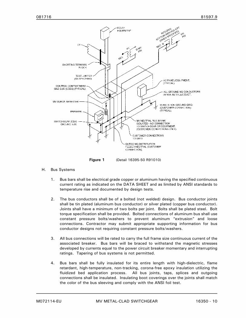
081716 81597.9
M072114-EU MV METAL-CLAD SWITCHGEAR 16350 - 10
Figure 1 (Detail 16395-50 R91010)
H. Bus Systems
1. Bus bars shall be electrical grade copper or aluminum having the specified continuous
current rating as indicated on the DATA SHEET and as limited by ANSI standards to
temperature rise and documented by design tests.
2. The bus conductors shall be of a bolted (not welded) design. Bus conductor joints
shall be tin plated (aluminum bus conductor) or silver plated (copper bus conductor).
Joints shall have a minimum of two bolts per joint. Bolts shall be plated steel. Bolt
torque specification shall be provided. Bolted connections of aluminum bus shall use
constant pressure bolts/washers to prevent aluminum “extrusion” and loose
connections. Contractor may submit appropriate supporting information for bus
conductor designs not requiring constant pressure bolts/washers.
3. All bus connections will be rated to carry the full frame size continuous current of the
associated breaker. Bus bars will be braced to withstand the magnetic stresses
developed by currents equal to the power circuit breaker momentary and interrupting
ratings. Tapering of bus systems is not permitted.
4. Bus bars shall be fully insulated for its entire length with high-dielectric, flame
retardant, high-temperature, non-tracking, corona-free epoxy insulation utilizing the
fluidized bed application process. All bus joints, taps, splices and outgoing
connections shall be insulated. Insulating boot coverings over the joints shall match
the color of the bus sleeving and comply with the ANSI foil test.
081716 81597.9
M072114-EU MV METAL-CLAD SWITCHGEAR 16350 - 11
5. All bus supports and other insulating material subject to line-to-line or line-to-ground
voltages shall be of high grade wet process porcelain (15.0 kV and above) or
cycloaliphatic epoxy (8.25 kV and below), including stationary primary disconnects.
I. Circuit Breakers:
1. Circuit breakers shall have one vacuum interrupter per phase. Breakers of same type
and rating shall be completely interchangeable. The closing speed of the moving
contacts is to be independent of both the control voltage and the operator. Provide a
full front shield on the breaker. Secondary control circuits shall be connected
automatically with a self-aligning, self-engaging plug and receptacle arrangement
when the circuit breaker is racked into the connected position. Provision shall be
made for secondary control plug to be manually connected in test position.
2. Operator Mechanism (As specified on Data Sheet):
a. Spring Breaker Operator: Circuit breaker utilizing a motor charged spring operator
shall provide an open/close/open cycle without recharging of the spring
mechanism. Spring charged stored energy mechanism shall be normally charged
by a universal motor with provisions for manual handle for manual emergency
closing or testing. The motor shall recharge spring in ten (10) seconds or less.
b. Magnetic Actuator Breaker Operator: Circuit breaker utilizing a magnetic actuator
shall incorporate a stored energy process to provide an open/close/open cycle
without electrical power supply to the operator. The stored energy equipment
shall recharge in ten (10) seconds or less.
3. An interlocking system shall be provided to prevent racking a closed circuit breaker to
or from any position. Additional interlock shall automatically discharge the stored-
energy operating mechanism springs upon removal of the breaker out of the
compartment.
J. Power System Switches
1. Switches shall be three-pole, single-throw group operated. The mechanism shall be
metal to metal linkage with quick make and break operation. The mechanism shall be
direct drive or chain linkage. Cable type switch operator linkage is not acceptable.
Switches shall be operated without opening circuit breaker or other compartment
doors. Suitable barriers shall be positioned to prevent flashovers phase-to-phase or
phase-to-ground (enclosure/cubicle/section).
K. Instrument Transformers
1. Current transformers shall be of the window type with ratios as indicated on the
Contract Drawings. They shall have sufficient thermal and mechanical capacity to
withstand the maximum momentary current rating of the breakers. All current
transformers shall be properly identified for polarity with standard marking symbols.
The current transformer assembly shall be insulated for the full voltage rating of the
switchgear. Relaying and metering accuracy shall conform to ANSI Standards.
a. All ratios of all current transformer circuits shall be wired to shorting-type
terminal blocks located in the circuit breaker compartment. Terminal blocks shall
be marked as to CT location and Ratio.
081716 81597.9
M072114-EU MV METAL-CLAD SWITCHGEAR 16350 - 12
b. One (1) GE 6 pole PK-2 test block shall be installed on the relay/control panel
compartment door for each CT circuit. This test block shall be wired between
the shorting terminal block and relays/meters, or as shown on the Contract
Documents.
c. CT's having an insulation rating of 600V with fully insulated bus centered in the
transformer window opening, are acceptable when corona, hi-pot, and impulse
tests prove a satisfactory arrangement. Tests shall be performed on a similar CT
installation in the switchgear manufacturer’s equipment and certified test reports
shall be submitted with the approval drawings when requested.
d. Phase CT's shall be mounted over stationary primary disconnects. Ground fault
sensor CT's shall be mounted in cable compartments and sized to accommodate
power cables and reliable relay operation.
e. Current Transformer requirements, ratios, and accuracy class shall be as listed on
the DATA SHEET.
2. Voltage Transformers
a. Voltage transformers (VTs) and their primary fuses shall be mounted in separate
steel compartments. Primary connections to the transformers shall be insulated
and enter the compartment through porcelain or cycloaliphatic epoxy bushings.
Each set of voltage transformers and fuses shall be mounted on the tilt out steel
carriage which will be capable of disconnecting the transformer fuses from their
voltage source and removing them from the structure. This removing mechanism
shall be so arranged that full access to the transformers cannot be accomplished
until the fuses are disconnected from the structure and grounded. When moved
to a full out position, the transformer fuses and VT windings shall be
automatically connected to a ground stud. Primary contacts shall be insulated
from the structure by porcelain or cycloaliphatic epoxy supports, shall be self-
aligning, and shall have silver to silver contact surfaces.
i) Relay and metering VT’s shall be of the ratio indicated on the Contract
Drawings and shall comply with ANSI C57.13.
b. Revenue metering VTs shall be accuracy class 0.3 as covered by Table 6 in IEEE
Std C57.13-2008 with standard burdens as given in Table 15, except omit ZZ
burden for transformers rated 26,000 volts and below and omit Z and ZZ burdens
for transformers rated 4,800 volts and below.
1) A ratio and phase-angle test on each ratio of each VT. Tests shall be made
at 90 percent, 100 percent, and 110 percent secondary voltage at 0-colt-
ampere burden and at the maximum standard IEEE burden for which 0.3
accuracy class is guaranteed.
2) Four (4) copies of VT manufacturer’s Certified Test data shall be provide
prior to installation of the VT within the switchgear.
081716 81597.9
M072114-EU MV METAL-CLAD SWITCHGEAR 16350 - 13
L. Wiring
1. Relay and Control Panel Wiring shall be 600 volt, type SIS stranded switchboard wire,
AWG No. 14, 41 strands or as indicated below. It shall be UL Listed, Type VW-1,
90°C, tinned copper and provided with a permanent wire marking system identifying
the "from-to" wire designation every 4 to 6 inches along the entire length of the wire.
These designations shall match the wiring diagram. Conductor size designations shall
be shown on schematics and wiring drawings.
a. The control and SCADA RTU wiring internal to the cubical or panel or between
adjacent cubicles or panels shall be AWG No. 14, 41 strands.
b. Wiring between the cubicles or panels and separately installed equipment
cabinets such as SCADA and AMR cabinets shall use TC cables as indicated
below. Conductors shall be AWG No. 14.
c. Current transformer/protective relay current wiring shall be AWG No. 12, 65
strands.
d. Conductors used as AC and DC “supply bus” for inter-panel AC and DC supply;
and conductors between the relay/control panels and the AC and DC breaker
panels shall be AWG No. 10, minimum. Conductor color code shall meet
National Electric Code requirements.
e. Annunciator and alarm system wiring shall be AWG No. 16.
2. Tray Cables
a. When the use of multi-conductor cables is deemed appropriate for the function
by the Contractor, type TC cable shall be used.
1) Cable conductor size shall be based on function as listed in Paragraph 2.03,
O. - Wiring.
2) Control and low voltage power cable insulation shall be Ethylene-Propylene
Rubber (EPR) rated for 90°C/75°C wet conditions. Insulation shall be rated
for 600 Volts AC, 250 Volts DC. Polyethylene jacket shall be provided for
single conductor and multiple conductor cable.
b. Circuits using single conductors or multiple conductor cables shall be identified in
accordance with ICEA/NEMA Method 1. Color sequence E-1 shall be used for AC
power circuits. Color sequence E-2 shall be used for all DC power, control, and
instrument transformer secondary circuits. See Table below:
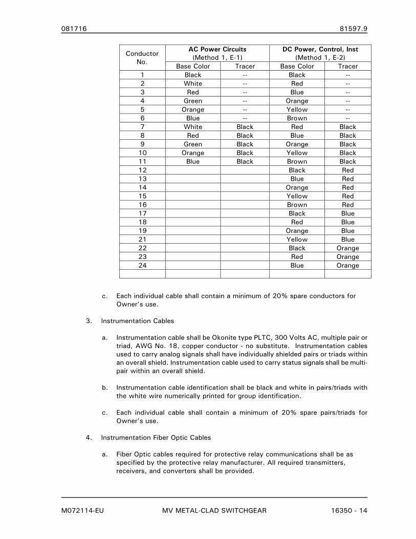
081716 81597.9
M072114-EU MV METAL-CLAD SWITCHGEAR 16350 - 14
c. Each individual cable shall contain a minimum of 20% spare conductors for
Owner’s use.
3. Instrumentation Cables
a. Instrumentation cable shall be Okonite type PLTC, 300 Volts AC, multiple pair or
triad, AWG No. 18, copper conductor - no substitute. Instrumentation cables
used to carry analog signals shall have individually shielded pairs or triads within
an overall shield. Instrumentation cable used to carry status signals shall be multi-
pair within an overall shield.
b. Instrumentation cable identification shall be black and white in pairs/triads with
the white wire numerically printed for group identification.
c. Each individual cable shall contain a minimum of 20% spare pairs/triads for
Owner’s use.
4. Instrumentation Fiber Optic Cables
a. Fiber Optic cables required for protective relay communications shall be as
specified by the protective relay manufacturer. All required transmitters,
receivers, and converters shall be provided.
Conductor
No.
AC Power Circuits
(Method 1, E-1)
DC Power, Control, Inst
(Method 1, E-2)
Base Color Tracer Base Color Tracer
1 Black -- Black --
2 White -- Red --
3 Red -- Blue --
4 Green -- Orange --
5 Orange -- Yellow --
6 Blue -- Brown --
7 White Black Red Black
8 Red Black Blue Black
9 Green Black Orange Black
10 Orange Black Yellow Black
11 Blue Black Brown Black
12 Black Red
13 Blue Red
14 Orange Red
15 Yellow Red
16 Brown Red
17 Black Blue
18 Red Blue
19 Orange Blue
21 Yellow Blue
22 Black Orange
23 Red Orange
24 Blue Orange
081716 81597.9
M072114-EU MV METAL-CLAD SWITCHGEAR 16350 - 15
b. Fiber Optic cables shall be installed for the Arc-Flash protection scheme.
These cables will be non-jacketed to allow for light to penetrate at any point
on the fiber. They shall be installed within the Circuit Breaker Compartments
including the Tie Breaker, Main Bus Compartment, Transfer Bus Compartment,
and Power Cable Exit Compartments in accordance with the Protective Relay
Manufacturer’s instructions.
M. Protective Relays and Controls
1. Relays and controls shall be as listed in the DATA SHEET and/or as shown on the
attached Contract Drawings.
2. Relays, meters, control switches, etc., shall be mounted on a formed front-hinged
panel for each circuit breaker compartment. Doors shall be equipped with a latch to
hold in the open position.
3. Phenolic nameplates, black with white core letters, shall be provided for all control and
transfer switches, instruments, relays, meters, and other major equipment items.
N. Surge Arresters
1. Surge arresters shall comply with ANSI C62.1 for the metal-oxide station class type
suitable for outdoor installations. Surge arresters shall be ANSI #70 gray, Ohio Brass
Type EVP - no substitute. Ratings shall be as listed in the DATA SHEET and/or as
shown on the attached Contract Drawings.
2. When surge arresters are specified, Contractor shall provide and install surge arrester
jumpers from arrester to Ground Bus and arrester to phase bus/cable connection.
O. Moisture Control Strip Heaters
1. Strip heaters shall be installed in circuit breaker compartment and MV Cable
Termination compartment as required to prevent condensation damage.
a. Breaker Compartment: One (1) strip heater providing 125 watts (minimum
operating wattage) shall be installed at an appropriate location to prevent
condensation in the breaker compartment.
b. MV Cable Termination Compartment: Two (2) strip heaters providing 125 watts
each (minimum operating wattage) shall be installed to prevent condensation
within the MV cable compartment. Strip heaters shall be installed with one (1)
heater on each side pan of the Cable Compartment in the lower areas of the
compartment located to avoid interference with Medium-Voltage cable
installation.
c. Other Compartments: Contractor shall determine the necessity of installing strip
heaters in other compartments as may be dictated by Contractor’s design.
d. Contractor shall provide heat calculations for any deviation of strip heater
locations or operating wattage.
2. Strip heaters shall be operated at 50% of rated voltage for extended heater life. For
example, 240 Vac rated strip heaters operated at 120 Vac.
081716 81597.9
M072114-EU MV METAL-CLAD SWITCHGEAR 16350 - 16
3. Strip Heater Control: Strip heater circuits shall be controlled by the AC Panel board
branch circuit breaker only. Thermostats, switches, or other control devices shall not
be installed.
4. Strip Heater Circuit Monitoring: An ammeter shall be provided at each cubicle to
monitor the heater circuit. Signage shall be provided that indicates the circuit load
current at the operating voltage.
2.04 NAMEPLATES
A. General
1. All nameplates shall be stainless steel with permanent engravings of the required data.
Engravings shall be finished with black coating to result in legible, black markings.
Nameplates shall be permanently affixed at locations clearly legible without subjecting
personnel to electrical or mechanical hazards.
B. Metal-Clad Switchgear
1. A separate nameplate shall be affixed to the Metal-Clad Switchgear. Nameplate data
shall contain the following information in addition to the data required by the
appropriate ANSI/IEEE Standard and Contractor’s Standard information.
a. Manufacturer
b. Model Number, Type, Serial Number
c. Year of Manufacture
d. Ratings:
i) Maximum Voltage
ii) Frequency
iii) Main Bus Ampacity
iv) Transfer Bus Ampacity
v) BIL
vi) Surge Arrester Data
e. Weight of complete assembly
f. Instruction Manual Number
g. Parts Manual Number
C. Associated Metal-Clad Switchgear Equipment
1. Associated metal-clad switchgear equipment including control power transformers,
instrument transformers, medium-voltage fuses, incoming source switches, transfer
bus switches, and bus tie switches shall have separate nameplates affixed within the
appropriate cubicle. The nameplate shall contain the following data:
a. Manufacturer
b. Transformer Voltage ratings
c. Transformer load ratings
d. Incoming Source Switch ratings
e. Transfer Bus Switch ratings
f. Bus Tie Switch ratings
081716 81597.9
M072114-EU MV METAL-CLAD SWITCHGEAR 16350 - 17
D. Circuit Breakers
1. A separate nameplate shall be affixed to each Circuit Breaker. Nameplate data shall
contain the following breaker and operating mechanism information in addition to the
data required by the appropriate ANSI/IEEE Standard and Contractor’s Standard
information.
a. Manufacturer
b. Model Number, Type, Serial Number
c. Year of Manufacture
d. Circuit Breaker Ratings (per ANSI C37.06-2009):
i) Frequency
ii) Continuous current
iii) Maximum voltage
iv) Rated continuous current
v) Rated short circuit current
vi) Maximum symmetrical interrupt capability
vii) Interrupting time
viii) BIL e. Operating Mechanism Ratings:
i) Closing control voltage range
ii) Tripping control voltage range
iii) Closing current
iv) Tripping current
v) Motor start and run currents
vi) Operating spring recharge time
vii) Pressure alarm switch operating range
viii) Pressure trip switch operating range
ix) Low pressure lockout switch closing and opening pressure
f. Weight of complete assembly
g. Instruction Manual Number
h. Wiring Diagram Number
i. Parts Manual Number
E. Current Transformers
1. A separate nameplate for current transformers shall be affixed in each appropriate
cubicle to identify the CTs located within. Nameplate data shall contain the following
current transformer information in addition to the data required by the appropriate
ANSI/IEEE Standard and Contractor’s Standard information.
a. Manufacturer
b. Model Number, Type, Serial Number
c. Rated frequency
d. American National Standard accuracy class
e. Connection chart showing:
i) Full winding development
ii) Taps
iii) Ratio in terms of primary and secondary currents
iv) Polarity
f. Location of CT
g. Curve sheet number
081716 81597.9
M072114-EU MV METAL-CLAD SWITCHGEAR 16350 - 18
PART 3 EXECUTION
3.01 FABRICATION
A. Each equipment bay shall be a separately constructed cubicle assembled to form a rigid
free-standing unit. Minimum sheet metal thickness shall be 11-gauge steel on all exterior
surfaces. Adjacent bays shall be securely bolted together to form an integrated rigid
structure. The rear covers shall be removable to assist installation and maintenance of bus
and cables. Each individual unit shall be braced to prevent distortion.
B. Phase arrangement shall be A-B-C left to right, front to back, and top to bottom when
viewed from the front of each breaker cubicle. All buses shall be identified accordingly in
each cubicle/section.
C. Dimensions: Outdoor Switchgear equipment dimensions will vary with enclosure style and
circuit breaker selection. Maximum height shall be 110 in for non-walk-in and 120 in for
walk-in style enclosure, measured to peak of the sloped roof or as indicated on Contract
Drawings.
D. The metal-clad switchgear shall be fully assembled, inspected, and tested at the factory
prior to shipment. Large line-ups shall be split to permit normal shipping and handling as
well as for ease of rejoining at the job site.
E. Wiring connections across a shipping split shall be implemented with a terminal block on
one side of the split and conductors “rolled back” for shipment on the other side. Use of
terminal blocks on each side of the split with jumpers between terminal blocks is not
permitted. Shipping Split Terminal Blocks shall be Owner accessible after the switchgear is
reassembled for inspection and testing.
F. MV Cable compartments shall have provisions for mounting cable-pulling equipment for the
installation of power system cable.
G. All conductors for AC and DC circuits shall be sized and be color coded in accordance with
all applicable codes as listed in Article 1.06 - REFERENCE STANDARDS unless otherwise
noted in these specifications or Contract Documents.
H. All instrument transformer circuit shall be grounded at one location. These grounds shall be
located at the appropriate PK-2 test block, accessible terminal block, or as indicated on the
Contract Drawings.
I. Panel wiring shall be labeled on both ends of the conductor as a minimum. All relays and
equipment shall be pre-wired to terminal blocks.
J. AC and DC supplies for each cubicle shall be separately protected. Close and Trip circuits
shall be isolated and separately protected.
K. Knife switches for all AC, DC, and circuit breaker Close and Trip circuits shall be installed in
each cubicle, or as shown on the Contract Drawings.
L. Circuit Breaker close control wiring shall be designed for lockout by external lockout relay,
when specified on Contact Drawings and/or DATA SHEET. Connections shall be readily
accessible at cubicle terminal blocks.
081716 81597.9
M072114-EU MV METAL-CLAD SWITCHGEAR 16350 - 19
M. Test block wiring: All incoming (source) wiring to PK-2 test blocks, when specified on the
Contract Drawings, shall be terminated on the bottom of the block and the outgoing (relay)
wiring shall be terminated on the top of the block. A-phase shall be on left as viewed from
front of panelboard, for current and potential circuits.
N. Terminal blocks and/or lug strips utilized for AC or DC supply buses shall be suitable for the
required conductor sizes.
O. Suitable wiring protectors shall be used at all locations involving wiring that crosses hinged
panels and doors.
P. All circuits for connection to devices external to the control panel shall be terminated on
600 volt, 30 ampere, twelve point terminal blocks with washer head screws.
Q. Conductor terminals shall be uninsulated crimp type of suitable size for the conductor.
R. Terminal blocks shall be located in the relay/control panel subpan, mounted in a vertical
fashion.
S. Control cable/conductor wireways shall be sized to accommodate the Contractor’s
switchgear design requirements and shall provide an additional space of 25% for the
Owner’s use.
T. Control cable entrances (cables from external power system equipment) shall be
consolidated in a reasonable and logical manner to aid in the switchgear installation and
design of the switchgear foundation/underground conduit layout.
3.02 FACTORY FINISHING
A. All steel parts, except galvanized (if used), shall be cleaned and a zinc-phosphate pre-
treatment applied prior to finish application.
B. Primer shall be suitable for the finish to be applied. Primer shall be applied to an average
thickness of 1 mil.
C. Paint/coating shall be TGIC polyester powder, applied electrostatically through air.
Following paint/coating application, parts shall be baked to produce a hard durable finish.
The average thickness of the paint film shall be 3.0 mils. Paint film shall be uniform in
color and free from blisters, sags, flaking and peeling.
1. Contractor may submit contractor’s standard paint/coating materials and process for
Engineer’s review and approval decision.
D. Adequacy of paint finish to inhibit the buildup of rust on ferrous metal materials shall be
tested and evaluated per Clause 6.29 of IEEE C37.20.2-1999. Salt spray tests in
accordance with ASTM #D-1654 and #B-117 shall be performed on a periodic basis to
provide conformance with the corrosion resistance standard of at least 2500 hours
minimum.
3.03 FACTORY TESTING
A. Switchgear: Perform all applicable tests designated as “Production Testing” as described in
ANSI/IEEE C37.02.2 Standard for Metal-Clad and Station-Type Switchgear.
081716 81597.9
M072114-EU MV METAL-CLAD SWITCHGEAR 16350 - 20
B. Power Circuit Breakers: Perform all applicable tests designated as “Routine” as described in
ANSI/IEEE C37.09 Standard Test Procedure for AC High Voltage Circuit Breakers rated on a
symmetrical current basis.
C. Revenue Metering Voltage Transformers: A ratio and phase-angle test on each VT. Tests
shall be made at 90 percent, 100 percent, and 110 percent secondary voltage at 0-volt-
ampere burden and at the maximum standard IEEE burden for which 0.3 accuracy class is
guaranteed.
3.04 INSTALLATION
A. General
1. Contractor is responsible for the installation of the switchgear and switchgear housing
on the Owner furnished foundation pad in accordance with Section 16162
SUBSTATION CONTROL AND SWITCHGEAR HOUSING.
2. Contractor is responsible for all required switchgear assembly, field testing of
assembled switchgear, and certification to Owner that switchgear is ready for
connection to Owner’s electric system.
3. Install in accordance with Contractor's instructions, applicable requirements of the
NEC and in accordance with recognized industry practices.
4. Inspect switchgear for evidence of damage and verify that Owner furnished
foundation pad surfaces are ready to receive work.
5. Inspect to confirm that all items and accessories are in accordance with specifications
and drawings.
6. Touch-up paint all chips and scratches with Contractor-supplied paint and leave
remaining paint with owner.
7. Clean all insulators and switchgear bus conductors.
B. Assembly
1. Assembly includes the electrical and mechanical assembly of all switchgear units,
subassemblies, shipping splits, and all other materials required to provide a complete
switchgear as specified in these Contract Documents.
2. Assembly includes installation and commissioning of the battery system when
specified in the Contract Documents. This includes:
a. Installation of the battery rack, spill containment, battery cells.
b. Commissioning of the battery system per manufacturer’s instructions:
i) Cell fluid levels
ii) Inter-cell connections and charger connections
iii) Charger voltage settings - volts per cell charge levels
iv) Initial battery charging (commissioning battery charge)
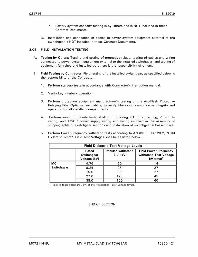
081716 81597.9
M072114-EU MV METAL-CLAD SWITCHGEAR 16350 - 21
c. Battery system capacity testing is by Others and is NOT included in these
Contract Documents.
3. Installation and connection of cables to power system equipment external to the
switchgear is NOT included in these Contract Documents.
3.05 FIELD INSTALLATION TESTING
A. Testing by Others: Testing and setting of protective relays, testing of cables and wiring
connected to power system equipment external to the installed switchgear, and testing of
equipment furnished and installed by others is the responsibility of others.
B. Field Testing by Contractor: Field testing of the installed switchgear, as specified below is
the responsibility of the Contractor.
1. Perform start-up tests in accordance with Contractor's instruction manual.
2. Verify key interlock operation.
3. Perform protection equipment manufacturer’s testing of the Arc-Flash Protective
Relaying Fiber-Optic sensor cabling to verify fiber-optic sensor cable integrity and
operation for all installed compartments.
4. Perform wiring continuity tests of all control wiring, CT current wiring, VT supply
wiring, and AC/DC power supply wiring and wiring involved in the assembly of
shipping splits of switchgear sections and installation of switchgear subassemblies.
5. Perform Power-Frequency withstand tests according to ANSI/IEEE C37.20.2, “Field
Dielectric Tests”. Field Test Voltages shall be as listed below:
Field Dielectric Test Voltage Levels Rated
Switchgear
Voltage (kV)
Impulse withstand
(BIL) (kV)
Field Power Frequency
withstand Test Voltage
kV (rms)1
MC
Switchgear
4.76 60 14
8.25 95 27
15.0 95 27
27.0 125 45
38.0 150 60
1. Test voltages listed are 75% of the “Production Test” voltage levels.
END OF SECTION
081716 81597.9
M072114-EU MV METAL-CLAD SWITCHGEAR DATA SHEET 16350D-1
SECTION 16350D
MV METAL-CLAD SWITCHGEAR
DATA SHEET
PART 1 GENERAL
1.01 SECTION INCLUDES
A. This specification section in conjunction with Section 16350 - MV METAL-CLAD
SWITCHGEAR includes the fabrication, delivery, and installation of medium voltage
metal-clad switchgear, as required to meet the Contractor’s obligations, as stated in the
proposal section of these specifications.
B. Medium voltage (5 kV through 27 kV) free-standing or close-coupled metal-clad
switchgear with vacuum or SF6 circuit breaker interrupters, protective relaying,
metering, and auxiliary equipment.
1.02 RELATED SECTIONS
A. DIVISIONS 0 and 1 - PROPOSAL DOCUMENTS, CONTRACT DOCUMENTS AND
GENERAL REQUIREMENTS: These shall apply to all work included in this section.
B. Section 16350 - MV METAL-CLAD SWITCHGEAR
1.03 SERVICE CONDITIONS
A. The MV Metal-Clad Switchgear will be installed in a 161:13 kV substation for
distribution feeder protection.
B. Elevation: Less than 3,000 feet above mean sea level.
C. Ambient Temperature Range: -25°C to 40°C
D. System Voltage
Nominal: 15,000 Volts
Operational: 13,090 Volts
Frequency: 60 Hertz
E. Substation Transformer Bank:
2 161,000/13,090 kV
Delta/Wye - GND
18/24/30//33 MVA ONAN/ONAF/ONAF
10.5 % Z
F. System Grounding and Fault Current Levels:
13 kV Bus:
solid
Coefficient of grounding 0.558
081716 81597.9
M072114-EU MV METAL-CLAD SWITCHGEAR DATA SHEET 16350D-2
16,822 3-Phase/ Amps X/R=21.50
18,080 Single-Phase/G Amps X/R=22.46
G. System Operation:
1. Proposed Reclosing Duty Cycle:
Distribution Feeder Breakers: O – 0.3s – CO - 15s - CO - 45s - CO
Bus Tie Breakers: O – 15s – CO – 3 min - CO
2. Feeder circuits: underground cable distribution feeder exits.
H. Seismic: Metal-clad Switchgear shall meet the seismic requirements as listed under
“Structural Requirements” in Section 16162 - SUBSTATION CONTROL AND
SWITCHGEAR HOUSING
I. Foundation Type: monolithic concrete pad
PART 2 PRODUCTS
2.01 CONTRACTORS
A. Metal-clad switchgear by the following Contractors are approved for the Project:
1. Central Electric
2. Powercon Corp
B. Circuit Breakers by the following Contractors are approved for this Project:
1. Eaton Cutler Hammer
2. General Electric/Powell Electric
2.02 METAL-CLAD SWITCHGEAR ASSEMBLY
A. The metal-clad switchgear shall consist of indoor switchgear in an outdoor electrical
equipment enclosure containing circuit breakers and the necessary accessory
components all factory assembled (except for necessary shipping splits) and
operationally checked. The assembly shall be a self-supporting and floor mounted on a
level concrete pad or piers as indicated on the Contract Drawings. The integrated
switchgear assembly shall withstand the effects of closing, carrying and interrupting
currents up to the assigned maximum short circuit rating.
B. Switchgear Insulation Class: Class 105
C. Maximum Design Voltage: 15.0 kV.
D. Impulse Withstand (Basic Impulse Level): 95 kV.
E. Power Frequency Withstand: 36 kV, 1 minute test.
F. Main Bus: silver-plated copper 3000 amps, continuous.
G. Transfer Bus: silver-plated copper, 1200 amps, continuous.
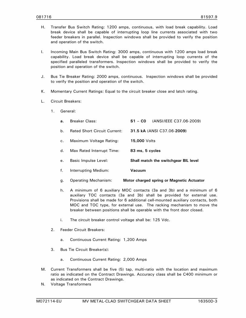
081716 81597.9
M072114-EU MV METAL-CLAD SWITCHGEAR DATA SHEET 16350D-3
H. Transfer Bus Switch Rating: 1200 amps, continuous, with load break capability. Load
break device shall be capable of interrupting loop line currents associated with two
feeder breakers in parallel. Inspection windows shall be provided to verify the position
and operation of the switch.
I. Incoming Main Bus Switch Rating: 3000 amps, continuous with 1200 amps load break
capability. Load break device shall be capable of interrupting loop currents of the
specified paralleled transformers. Inspection windows shall be provided to verify the
position and operation of the switch.
J. Bus Tie Breaker Rating: 2000 amps, continuous. Inspection windows shall be provided
to verify the position and operation of the switch.
K. Momentary Current Ratings: Equal to the circuit breaker close and latch rating.
L. Circuit Breakers:
1. General:
a. Breaker Class: S1 – C0 (ANSI/IEEE C37.06-2009)
b. Rated Short Circuit Current: 31.5 kA (ANSI C37.06-2009)
c. Maximum Voltage Rating: 15,000 Volts
d. Max Rated Interrupt Time: 83 ms, 5 cycles
e. Basic Impulse Level: Shall match the switchgear BIL level
f. Interrupting Medium: Vacuum
g. Operating Mechanism: Motor charged spring or Magnetic Actuator
h. A minimum of 6 auxiliary MOC contacts (3a and 3b) and a minimum of 6
auxiliary TOC contacts (3a and 3b) shall be provided for external use.
Provisions shall be made for 6 additional cell-mounted auxiliary contacts, both
MOC and TOC type, for external use. The racking mechanism to move the
breaker between positions shall be operable with the front door closed.
i. The circuit breaker control voltage shall be: 125 Vdc.
2. Feeder Circuit Breakers:
a. Continuous Current Rating: 1,200 Amps
3. Bus Tie Circuit Breaker(s):
a. Continuous Current Rating: 2,000 Amps
M. Current Transformers shall be five (5) tap, multi-ratio with the location and maximum
ratio as indicated on the Contract Drawings. Accuracy class shall be C400 minimum or
as indicated on the Contract Drawings.
N. Voltage Transformers
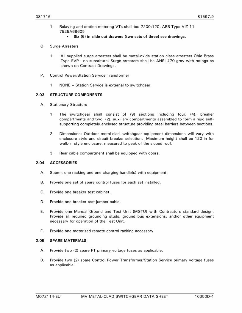
081716 81597.9
M072114-EU MV METAL-CLAD SWITCHGEAR DATA SHEET 16350D-4
1. Relaying and station metering VTs shall be: 7200:120, ABB Type VIZ-11,
7525A68605
• Six (6) in slide out drawers (two sets of three) see drawings.
O. Surge Arresters
1. All supplied surge arresters shall be metal-oxide station class arresters Ohio Brass
Type EVP - no substitute. Surge arresters shall be ANSI #70 gray with ratings as
shown on Contract Drawings.
P. Control Power/Station Service Transformer
1. NONE – Station Service is external to switchgear.
2.03 STRUCTURE COMPONENTS
A. Stationary Structure
1. The switchgear shall consist of (9) sections including four, (4), breaker
compartments and two, (2), auxiliary compartments assembled to form a rigid self-
supporting completely enclosed structure providing steel barriers between sections.
2. Dimensions: Outdoor metal-clad switchgear equipment dimensions will vary with
enclosure style and circuit breaker selection. Maximum height shall be 120 in for
walk-in style enclosure, measured to peak of the sloped roof.
3. Rear cable compartment shall be equipped with doors.
2.04 ACCESSORIES
A. Submit one racking and one charging handle(s) with equipment.
B. Provide one set of spare control fuses for each set installed.
C. Provide one breaker test cabinet.
D. Provide one breaker test jumper cable.
E. Provide one Manual Ground and Test Unit (MGTU) with Contractors standard design.
Provide all required grounding studs, ground bus extensions, and/or other equipment
necessary for operation of the Test Unit.
F. Provide one motorized remote control racking accessory.
2.05 SPARE MATERIALS
A. Provide two (2) spare PT primary voltage fuses as applicable.
B. Provide two (2) spare Control Power Transformer/Station Service primary voltage fuses
as applicable.
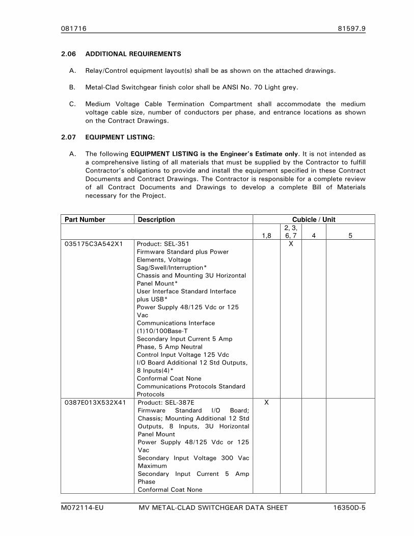
081716 81597.9
M072114-EU MV METAL-CLAD SWITCHGEAR DATA SHEET 16350D-5
2.06 ADDITIONAL REQUIREMENTS
A. Relay/Control equipment layout(s) shall be as shown on the attached drawings.
B. Metal-Clad Switchgear finish color shall be ANSI No. 70 Light grey.
C. Medium Voltage Cable Termination Compartment shall accommodate the medium
voltage cable size, number of conductors per phase, and entrance locations as shown
on the Contract Drawings.
2.07 EQUIPMENT LISTING:
A. The following EQUIPMENT LISTING is the Engineer’s Estimate only. It is not intended as
a comprehensive listing of all materials that must be supplied by the Contractor to fulfill
Contractor’s obligations to provide and install the equipment specified in these Contract
Documents and Contract Drawings. The Contractor is responsible for a complete review
of all Contract Documents and Drawings to develop a complete Bill of Materials
necessary for the Project.
Part Number Description Cubicle / Unit
1,8 2, 3, 6, 7 4 5
035175C3A542X1 Product: SEL-351
Firmware Standard plus Power
Elements, Voltage
Sag/Swell/Interruption*
Chassis and Mounting 3U Horizontal
Panel Mount*
User Interface Standard Interface
plus USB*
Power Supply 48/125 Vdc or 125
Vac
Communications Interface
(1)10/100Base-T
Secondary Input Current 5 Amp
Phase, 5 Amp Neutral
Control Input Voltage 125 Vdc
I/O Board Additional 12 Std Outputs,
8 Inputs(4)*
Conformal Coat None
Communications Protocols Standard
Protocols
X
0387E013X532X41
Product: SEL-387E
Firmware Standard I/O Board;
Chassis; Mounting Additional 12 Std
Outputs, 8 Inputs, 3U Horizontal
Panel Mount
Power Supply 48/125 Vdc or 125
Vac
Secondary Input Voltage 300 Vac
Maximum
Secondary Input Current 5 Amp
Phase
Conformal Coat None
X
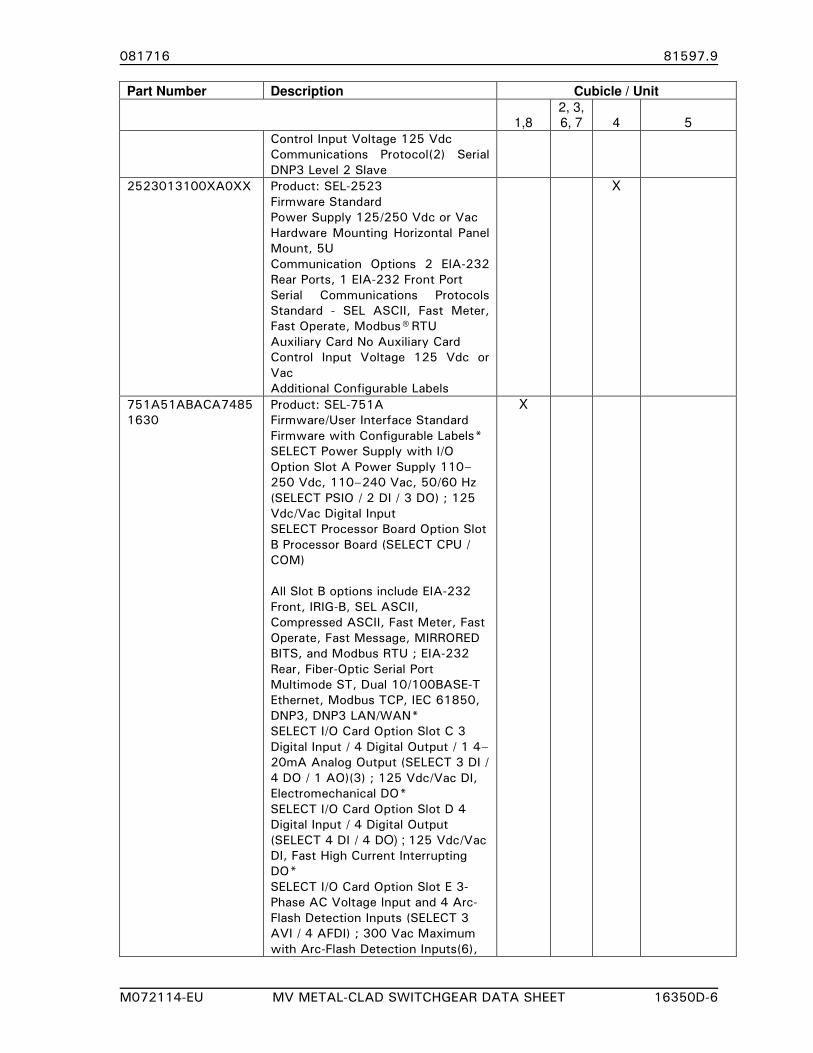
081716 81597.9
M072114-EU MV METAL-CLAD SWITCHGEAR DATA SHEET 16350D-6
Part Number Description Cubicle / Unit
1,8 2, 3, 6, 7 4 5
Control Input Voltage 125 Vdc
Communications Protocol(2) Serial
DNP3 Level 2 Slave
2523013100XA0XX
Product: SEL-2523
Firmware Standard
Power Supply 125/250 Vdc or Vac
Hardware Mounting Horizontal Panel
Mount, 5U
Communication Options 2 EIA-232
Rear Ports, 1 EIA-232 Front Port
Serial Communications Protocols
Standard - SEL ASCII, Fast Meter,
Fast Operate, Modbus® RTU
Auxiliary Card No Auxiliary Card
Control Input Voltage 125 Vdc or
Vac
Additional Configurable Labels
X
751A51ABACA7485
1630
Product: SEL-751A
Firmware/User Interface Standard
Firmware with Configurable Labels*
SELECT Power Supply with I/O
Option Slot A Power Supply 110–
250 Vdc, 110–240 Vac, 50/60 Hz
(SELECT PSIO / 2 DI / 3 DO) ; 125
Vdc/Vac Digital Input
SELECT Processor Board Option Slot
B Processor Board (SELECT CPU /
COM)
All Slot B options include EIA-232
Front, IRIG-B, SEL ASCII,
Compressed ASCII, Fast Meter, Fast
Operate, Fast Message, MIRRORED
BITS, and Modbus RTU ; EIA-232
Rear, Fiber-Optic Serial Port
Multimode ST, Dual 10/100BASE-T
Ethernet, Modbus TCP, IEC 61850,
DNP3, DNP3 LAN/WAN*
SELECT I/O Card Option Slot C 3
Digital Input / 4 Digital Output / 1 4–
20mA Analog Output (SELECT 3 DI /
4 DO / 1 AO)(3) ; 125 Vdc/Vac DI,
Electromechanical DO*
SELECT I/O Card Option Slot D 4
Digital Input / 4 Digital Output
(SELECT 4 DI / 4 DO) ; 125 Vdc/Vac
DI, Fast High Current Interrupting
DO*
SELECT I/O Card Option Slot E 3-
Phase AC Voltage Input and 4 Arc-
Flash Detection Inputs (SELECT 3
AVI / 4 AFDI) ; 300 Vac Maximum
with Arc-Flash Detection Inputs(6),
X
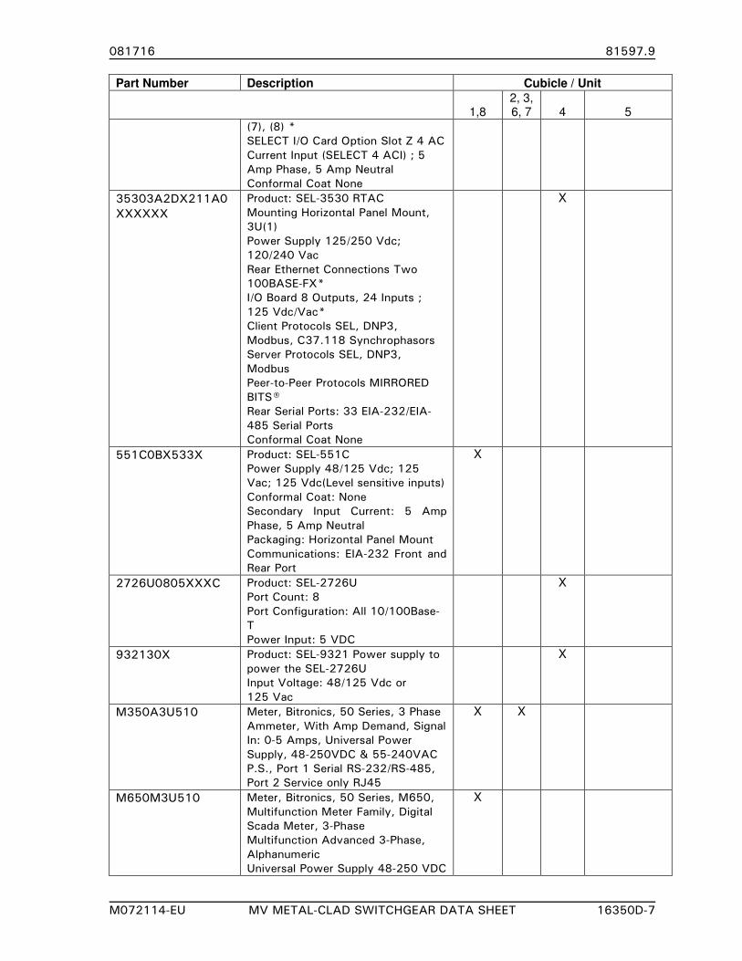
081716 81597.9
M072114-EU MV METAL-CLAD SWITCHGEAR DATA SHEET 16350D-7
Part Number Description Cubicle / Unit
1,8 2, 3, 6, 7 4 5
(7), (8) *
SELECT I/O Card Option Slot Z 4 AC
Current Input (SELECT 4 ACI) ; 5
Amp Phase, 5 Amp Neutral
Conformal Coat None
35303A2DX211A0
XXXXXX
Product: SEL-3530 RTAC
Mounting Horizontal Panel Mount,
3U(1)
Power Supply 125/250 Vdc;
120/240 Vac
Rear Ethernet Connections Two
100BASE-FX*
I/O Board 8 Outputs, 24 Inputs ;
125 Vdc/Vac*
Client Protocols SEL, DNP3,
Modbus, C37.118 Synchrophasors
Server Protocols SEL, DNP3,
Modbus
Peer-to-Peer Protocols MIRRORED
BITS®
Rear Serial Ports: 33 EIA-232/EIA-
485 Serial Ports
Conformal Coat None
X
551C0BX533X Product: SEL-551C
Power Supply 48/125 Vdc; 125
Vac; 125 Vdc(Level sensitive inputs)
Conformal Coat: None
Secondary Input Current: 5 Amp
Phase, 5 Amp Neutral
Packaging: Horizontal Panel Mount
Communications: EIA-232 Front and
Rear Port
X
2726U0805XXXC Product: SEL-2726U
Port Count: 8
Port Configuration: All 10/100Base-
T
Power Input: 5 VDC
X
932130X Product: SEL-9321 Power supply to
power the SEL-2726U
Input Voltage: 48/125 Vdc or
125 Vac
X
M350A3U510 Meter, Bitronics, 50 Series, 3 Phase
Ammeter, With Amp Demand, Signal
In: 0-5 Amps, Universal Power
Supply, 48-250VDC & 55-240VAC
P.S., Port 1 Serial RS-232/RS-485,
Port 2 Service only RJ45
X X
M650M3U510 Meter, Bitronics, 50 Series, M650,
Multifunction Meter Family, Digital
Scada Meter, 3-Phase
Multifunction Advanced 3-Phase,
Alphanumeric
Universal Power Supply 48-250 VDC
X

081716 81597.9
M072114-EU MV METAL-CLAD SWITCHGEAR DATA SHEET 16350D-8
Part Number Description Cubicle / Unit
1,8 2, 3, 6, 7 4 5
/ 55-240 VAC
0-120 VAC, 0-5A Nom. Input
Three 5-Digit Red Led Displays
4.5" Square Face Plate, 6.5" Deep,
4" Round Case.
Serial (Programmable RS-232/RS-
485)
Service Only RJ45
ABB FT-19 Test switches. See
Contract Drawings for arrangement
details.
X X X X
8857DB 914A, 914B, 924A, 924B, 2101, 2201, 2301, 2401, 2001
Circuit Breaker Control Switch,
Electroswitch Series 24 CSR. See
Contract Drawings for details.
X X X
9323DE 2129A, 2229A, 2329A, 2429A
Circuit Breaker ‘A’ and ‘N’ Switch,
Electroswitch Series 24 CSR. See
Contract Drawings for details.
X
9303DD 2129N, 2229N, 2329N, 2429N
Circuit Breaker ‘N’ Switch,
Electroswitch Series 31 LSR. See
Contract Drawings for details.
X X
7825DD 9186, 9286
Electroswitch Lock-out relay
(LOR/ER) See Contract Drawings for
details.
X
Toggle switch X X X X
43-1 Electroswitch Series 24 Switch with
three spare decks & front reading
1) Normal, Bank1, Bank2,
Parallel,
X
Condensation heater ammeter, with
bypass toggle switch (See Drawing)
X X X X
Auxiliary Tripping Relay, General
Electric HGA11
X
States Type SMH, 10 pole test
switch, See Contract Drawings for
details.
X
Indicating Light, General Electric
Light Emitting Diode (LED) Type ET-
16, 125 VDC, red transparent color
cap.
X X X
Indicating Light, General Electric
Light Emitting Diode Type ET-16,
125 VDC, green transparent color
cap.
X X X
Indicating Light, General Electric
Light Emitting Diode (LED) Type ET-
16, 125 VDC, clear transparent
color cap.
X
Test Blocks, General Electric Type
PK-2, 6 and 4 pole as appropriate.
See Contract Drawings for details.
X X X
Phenolic fuse block, 2 pole, 250 X X X X
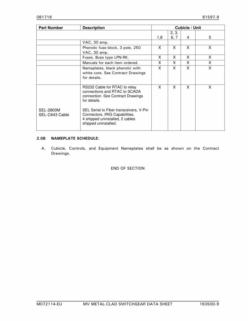
081716 81597.9
M072114-EU MV METAL-CLAD SWITCHGEAR DATA SHEET 16350D-9
Part Number Description Cubicle / Unit
1,8 2, 3, 6, 7 4 5
VAC, 30 amp.
Phenolic fuse block, 3 pole, 250
VAC, 30 amp.
X X X X
Fuses. Buss type LPN-RK. X X X X
Manuals for each item ordered. X X X X
Nameplates, black phenolic with
white core. See Contract Drawings
for details.
X X X X
RS232 Cable for RTAC to relay connections and RTAC to SCADA connection. See Contract Drawings for details.
X X X X
SEL-2800M SEL-C643 Cable
SEL Serial to Fiber transceivers, V-Pin Connectors, IRIG Capabilities, 4 shipped uninstalled, 2 cables shipped uninstalled.
2.08 NAMEPLATE SCHEDULE:
A. Cubicle, Controls, and Equipment Nameplates shall be as shown on the Contract
Drawings.
END OF SECTION
081716 81597.9
M022213-EU CENTRAL NICKEL-CADMIUM BATTERY SYSTEM 16632 - 1
SECTION 16632
CENTRAL NICKEL-CADMIUM BATTERY SYSTEM
PART 1. GENERAL
1.01 SECTION INCLUDES
A. Central Nickel-Cadmium Battery System, Rack, and Charger.
1.02 RELATED SECTIONS
A. DIVISIONS 0 and 1 - CONTRACT DOCUMENTS AND GENERAL REQUIREMENTS: These
shall apply to all work included in this section.
B. Section 16162 - SUBSTATION CONTROL AND SWITCHGEAR HOUSING.
C. Section 16345 - SUBSTATION RELAY CONTROL PANELS AND ASSOCIATED EQUIPMENT.
1.03 REFERENCES
A. Published Specifications, standards, tests, or recommended methods of trade, industry, or
governmental organizations apply to work in this section where cited in Section 01090 -
REFERENCE STANDARDS and in the listing below:
1. None
1.04 SUBMITTALS
A. Shop drawings shall be submitted for approval in accordance with Section 01301 -
SUBMITTALS and Section 01341 - SHOP DRAWINGS.
B. Submittals shall consist of, but not limited, to the following:
1. Battery Outline
2. Battery Rack Outline
3. Battery Rack Mounting Detail
4. Battery Cell Data
5. Charger Outline
6. Charger Specifications
7. Charger Schematics (Including Alarm Relays)
8. Charger Wiring Details
C. Final drawings shall be provided prior to shipment in accordance with Section 01721 -
PROJECT RECORD DOCUMENTS.
D. Operating and maintenance manuals, schematics, wiring diagrams and parts information,
for battery and charger system shall be provided in accordance with Section 01721 -
PROJECT RECORD DOCUMENTS.
081716 81597.9
M022213-EU CENTRAL NICKEL-CADMIUM BATTERY SYSTEM 16632 - 2
1.05 WARRANTY
A. All materials and equipment supplied under this specification shall be warranted as outlined
in Document 00711 - GENERAL CONDITIONS.
PART 2. PRODUCTS
2.01 BATTERY SYSTEM
A. The battery shall be MC 165P
B. Battery Cell Requirements:
1. Battery Cell Construction shall be of the Nickel Cadmium type.
2. The positive and negative plates shall be of the medium performance, pocket plate
design.
3. Battery capacity as specified below based on the 5-hour rate of discharge to 1.0 V per
cell at 25o C (77oF), in accordance with IEC 623.
4. Containers shall be manufactured from translucent, high impact resistant,
polypropylene.
5. Separators will be of the pin type with edge insulation.
6. All interconnecting hardware shall be provided. Inter-cell connectors shall be nickel
plated copper and inter-row connectors shall be flexible, insulated, compression lugged
cable of sufficient rating to withstand the short circuit current of the battery at the
rated voltage.
7. Flip top, flame arrester vents shall be provided for case of maintenance.
8. Number of Individual Cells: 94 Cells for 125 Vdc Systems.
9. Battery cell performance shall be as follows:
a. Float Voltage: 1.40 - 1.47 V per cell
b. Ampere-hour Capacity: 130 Ah
(5-hour rate to 1.0 V per cell, 25o C)
c. Discharge Rate Amperes: 60 Amps - 1 second
(to final 1.14 V per cell, 25o C) 18 Amps - 8 hours
2.02 BATTERY RACK
A. Battery Rack Construction:
1. Battery Rack and anchorage shall meet the Seismic Design Criteria as specified in
Section 16162, SUBSTATION CONTROL AND SWITCHGEAR HOUSING, 2.02,B.
081716 81597.9
M022213-EU CENTRAL NICKEL-CADMIUM BATTERY SYSTEM 16632 - 3
2. Tiers: 2
3. Steps: 2
4. Approximate Dimensions: 77" L x 29" D x 64" H
5. Rack dimensions shall provide minimum 36 inches working space between front edge
of rack and wall/barrier as provided in NEC 110.26.
B. Rack shall incorporate integral spill containment.
C. Provisions shall be provided to anchor each frame to the floor.
D. The racks shall be painted with a minimum of two coats of acid-resisting ANSI No. 61 gray
paint.
2.03 BATTERY CHARGER
A. The battery charger shall be La Marche TPSD for NiCad Battery operation.
B. The charger shall automatically charge the battery supplied under these specifications. The
charger shall maintain rated output voltage within +_ 1/2% from no load to full load with
input variations of +_ 10% Vac.
C. Battery Charger Requirements:
1. Charger Input: 1o/ , 240 Vac, 60 Hz.
2. Output-Voltage: 130 Vdc Nominal
-Current: 20 Amperes
3. Ripple (maximum): Less than 30 mV rms DC output ripple.
4. Range-Float: 127.88 – 133.40 Vdc
Equalize: 138.00 – 147.20 Vdc
2.04 DESIGN FEATURES
A. The following design features shall be provided:
1. DC ammeter, 2% accuracy.
2. DC voltmeter, 2% accuracy.
3. Automatic AC line compensation.
4. Automatic overload protection (current, limiting) to 110% of rated output, adjustable.
5. AC and DC circuit surge suppressors.
6. Manual float/equalize switch, front panel mounting.
7. Adjustable float/equalize levels, front panel mounted controls.
081716 81597.9
M022213-EU CENTRAL NICKEL-CADMIUM BATTERY SYSTEM 16632 - 4
8. Equalize timer, 0-72 hours.
9. AC input circuit breaker, 2-pole.
10. DC output circuit breaker, 2-pole.
11. AC input pilot light.
12. Ground detection lights.
13. Ground detection alarm relay with isolated, Form C output contacts and front panel
mounted indication light.
14. High and Low DC voltage alarm relays with isolated, Form C output contacts and front
panel mounted indication lights.
15. AC input power failure alarm relay with 0-300 second adjustable time delay, isolated
Form C output contacts and front panel mounted indication light.
16. Reverse battery protection.
17. DC output blocking, prevent discharge of battery system for charger failure or loss of
AC input.
B. Alarm output contacts shall be wired to terminal blocks suitable for termination of #12
AWG conductors. Contacts shall be rated for resistive loads of 0.5 amp at 130 Vdc,
minimum.
2.05 ACCESSORIES
A. The following accessories shall be provided for the battery system
1. Insulated terminal covers.
2. Cell number set, approximately 1/2" high.
3. Intercell and interstep connectors. All hardware including Intercell and inter-row
connectors.
PART 3. EXECUTION
3.01 COMMISIONING
A. The following shall be performed by the Contractor upon delivery:
1. The batteries shall be removed from shipping containers and placed into the rack.
2. All inter-battery and battery-to-charger connections shall be completed per the Battery
Manufacturer’s specifications and recommended torques.
3. All necessary terminal lubrications shall be applied per the Battery Manufacturer’s
specifications.
081716 81597.9
M022213-EU CENTRAL NICKEL-CADMIUM BATTERY SYSTEM 16632 - 5
4. Ensure liquid levels for all cells meet the Battery Manufacturer’s Specifications.
5. Visually inspect all Cells, Connections, Charger, and all other battery system
equipment for obvious flaws, warnings, insufficiencies.
B. Charging and testing requirements
1. A constant current charge shall be applied to the battery system for 10 hours at a
constant current of 0.2 times the rated Ah of the battery system or as the Battery
Manufacturer recommends. Follow all Battery Manufacturer’s Instructions on how this
is to be accomplished safely.
2. Measure battery system voltage at the battery terminals after charging has been
completed.
3. Operation of forced ventilation per these specifications.
4. Upon completion of commissioning the Contractor shall notify the Owner.
3.02 TESTING
A. Additional testing will be performed by the Owner upon notification from the Contractor
that the initial commission charging has been completed.
END OF SECTION