specifications and technical requirements for … · specifications and technical requirements for...
TRANSCRIPT

Solmax Premium HDPE Specification
Rev. 2.1 April 3, 2017 Page 1 of 27
SPECIFICATIONS AND TECHNICAL REQUIREMENTS FOR THE MANUFACTURING AND INSTALLATION
OF POLYETHYLENE GEOMEMBRANES
The following specification constitutes a guideline for the preparation of site specific geomembrane manufacturing and installation specification requirements. This information is provided for reference purposes only and is not intended as a warranty or guarantee. Solmax assumes no liability in connection with the use of this information. FOREWORD This specification guideline is for Premium HDPE geomembrane products manufactured by Solmax, the optimum choice of materials for a specific project remaining a decision to be made by the engineer. Solmax Product covered by this specification guideline; Solmax Premium HD, with Smooth, Singles-sided textured and Textured finishes

Solmax Premium HDPE Specification
Rev. 2.1 April 3, 2017 Page 2 of 27
Table of Content
1. GENERAL .................................................................................................................................................5
1.1 SCOPE ............................................................................................................................................................5 1.2 OPERATIONAL CONDITIONS ................................................................................................................................5 1.3 DEFINITIONS & ABBREVIATIONS ..........................................................................................................................5
1.3.1 Definitions .............................................................................................................................................5 1.3.2 Abbreviations ........................................................................................................................................5 1.3.3 Document References ..........................................................................................................................6
1.4 STANDARDS & CODES .......................................................................................................................................6 1.4.1 Standard & Codes .................................................................................................................................6
1.5 QUALITY SYSTEM REQUIREMENTS .......................................................................................................................7 1.6 SUBMITTALS ....................................................................................................................................................7
1.6.1 Construction Procedure ........................................................................................................................7 1.6.2 Panel Layout Drawing ...........................................................................................................................8 1.6.3 Manufacturer QC Documentation ........................................................................................................8
1.7 QUALIFICATIONS...............................................................................................................................................9 1.7.1 Manufacturer Qualifications .................................................................................................................9 1.7.2 Geomembrane Installer Qualifications .................................................................................................9
2. MATERIALS ........................................................................................................................................... 10
2.1 GENERAL ...................................................................................................................................................... 10 2.2 GEOMEMBRANE MATERIAL ............................................................................................................................. 10 2.3 GEOMEMBRANE MANUFACTURING QUALITY CONTROL ....................................................................................... 14 2.4 HDPE RESIN ................................................................................................................................................. 14 2.5 EXTRUDATE MATERIAL ................................................................................................................................... 14 2.6 ROLL IDENTIFICATION ..................................................................................................................................... 14 2.7 DELIVERY ..................................................................................................................................................... 15 2.8 STORAGE ...................................................................................................................................................... 15 2.9 HANDLING .................................................................................................................................................... 15 2.10 SAMPLES .................................................................................................................................................. 15 2.11 GEOMEMBRANE WARRANTY ....................................................................................................................... 15
2.11.1 Material Warranty ............................................................................................................................. 15 2.11.2 Installer Warranty .............................................................................................................................. 16
3. GEOMEMBRANE SUBGRADE PREPARATION ........................................................................................... 17
3.1 SUBGRADE PREPARATION ............................................................................................................................... 17 3.2 SUBGRADE MAINTENANCE .............................................................................................................................. 17
4. GEOMEMBRANE INSTALLATION ............................................................................................................ 18
4.1 GENERAL ...................................................................................................................................................... 18 4.2 SEAMING ..................................................................................................................................................... 19
4.2.1 General .............................................................................................................................................. 19 4.2.2 Personnel ........................................................................................................................................... 19 4.2.3 Seam Welding Equipment ................................................................................................................. 19 4.2.4 Seam Strength Requirements ............................................................................................................ 20 4.2.5 Weather Conditions ........................................................................................................................... 20
Solmax Premium HDPE Specification
Rev. 2.1 April 3, 2017 Page 3 of 27
4.2.6 Geomembrane Preparation ............................................................................................................... 20 4.2.7 Seam Lap ............................................................................................................................................ 20 4.2.8 Fusion Welding (Primary Welds) ....................................................................................................... 20 4.2.9 Extrusion Welding (Secondary Welds)............................................................................................... 21 4.2.10 Connections at Penetration and to Structures .................................................................................. 21
4.3 GEOMEMBRANE ANCHORAGE.......................................................................................................................... 21 4.4 CLEANING UP ............................................................................................................................................... 21
5. GEOMEMBRANE INSPECTION, TESTING & REPAIR .................................................................................. 22
5.1 VISUAL INSPECTIONS ...................................................................................................................................... 22 5.1.1 Geomembrane Visual Inspections ..................................................................................................... 22
5.2 SEAM TESTING .............................................................................................................................................. 22 5.2.1 Test Welds (In Field) .......................................................................................................................... 22 5.2.2 Non-Destructive Testing (In Field) ..................................................................................................... 23 5.2.3 Destructive Testing (In Field & In Laboratory) ................................................................................... 24
5.3 GEOMEMBRANE DEFECTS ............................................................................................................................... 25 5.3.1 Identification of Defects .................................................................................................................... 25 5.3.2 Evaluation of Defects ......................................................................................................................... 25 5.3.3 Wrinkles ............................................................................................................................................. 25
5.4 GEOMEMBRANE REPAIR ................................................................................................................................. 25 5.4.1 Geomembrane Repair Procedures .................................................................................................... 25 5.4.2 Verification of Seam Repairs .............................................................................................................. 25
5.5 TESTING & INSPECTION RECORDS ..................................................................................................................... 26
6. GEOMEMBRANE COMPLETION .............................................................................................................. 27
6.1 GEOMEMBRANE COMPLETION ACCEPTANCE CRITERIA ......................................................................................... 27
Solmax Premium HDPE Specification
Rev. 2.1 April 3, 2017 Page 4 of 27
Table 1 - Definitions ....................................................................................................................................................5 Table 2 - Abbreviations ...............................................................................................................................................5 Table 3 - Associated Document References ...............................................................................................................6 Table 4 - Standards .....................................................................................................................................................6 Table 5 (a) - Black Premium HDPE Geomembrane (Smooth) Technical Properties……………….…………………………….11 Table 5 (b) - Premium HDPE Geomembrane (Single Textured) Technical Properties……….………………………………….12 Table 5 (c) - Premium HDPE Geomembrane (Textured) Technical Properties……………….…………….………………………13 Table 6 - Resin Physical Properties……………………………………………………………………………………………..………………………15 Table 7 - Induced Slack Height at Varying Ambient Temperatures……………………………………………………………………..18 Table 8 - Weld Strength Requirements……………………………………………………………………………………………………………….23 Table 9 - Destructive Test Sample Allocation……………………………………………………………………………………………………..24
Solmax Premium HDPE Specification
Rev. 2.1 April 3, 2017 Page 5 of 27
1. General
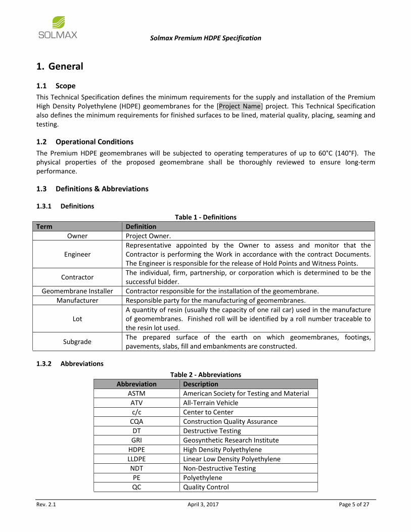
1.1 Scope
This Technical Specification defines the minimum requirements for the supply and installation of the Premium High Density Polyethylene (HDPE) geomembranes for the [Project Name] project. This Technical Specification also defines the minimum requirements for finished surfaces to be lined, material quality, placing, seaming and testing.
1.2 Operational Conditions
The Premium HDPE geomembranes will be subjected to operating temperatures of up to 60°C (140°F). The physical properties of the proposed geomembrane shall be thoroughly reviewed to ensure long-term performance.
1.3 Definitions & Abbreviations
1.3.1 Definitions
Table 1 - Definitions
Term Definition
Owner Project Owner.
Engineer Representative appointed by the Owner to assess and monitor that the Contractor is performing the Work in accordance with the contract Documents. The Engineer is responsible for the release of Hold Points and Witness Points.
Contractor The individual, firm, partnership, or corporation which is determined to be the successful bidder.
Geomembrane Installer Contractor responsible for the installation of the geomembrane.
Manufacturer Responsible party for the manufacturing of geomembranes.
Lot A quantity of resin (usually the capacity of one rail car) used in the manufacture of geomembranes. Finished roll will be identified by a roll number traceable to the resin lot used.
Subgrade The prepared surface of the earth on which geomembranes, footings, pavements, slabs, fill and embankments are constructed.
1.3.2 Abbreviations
Table 2 - Abbreviations
Abbreviation Description
ASTM American Society for Testing and Material
ATV All-Terrain Vehicle
c/c Center to Center
CQA Construction Quality Assurance
DT Destructive Testing
GRI Geosynthetic Research Institute
HDPE High Density Polyethylene
LLDPE Linear Low Density Polyethylene
NDT Non-Destructive Testing
PE Polyethylene
QC Quality Control
Solmax Premium HDPE Specification
Rev. 2.1 April 3, 2017 Page 6 of 27
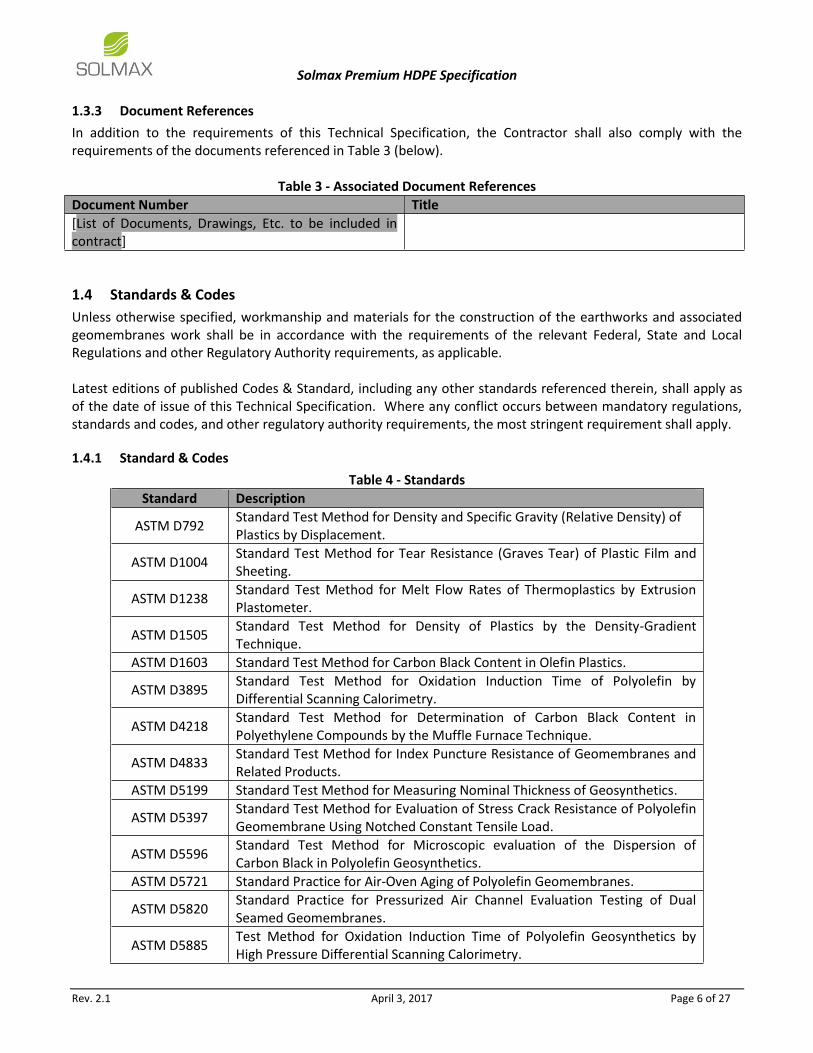
1.3.3 Document References
In addition to the requirements of this Technical Specification, the Contractor shall also comply with the requirements of the documents referenced in Table 3 (below).
Table 3 - Associated Document References
Document Number Title
[List of Documents, Drawings, Etc. to be included in contract]
1.4 Standards & Codes
Unless otherwise specified, workmanship and materials for the construction of the earthworks and associated geomembranes work shall be in accordance with the requirements of the relevant Federal, State and Local Regulations and other Regulatory Authority requirements, as applicable. Latest editions of published Codes & Standard, including any other standards referenced therein, shall apply as of the date of issue of this Technical Specification. Where any conflict occurs between mandatory regulations, standards and codes, and other regulatory authority requirements, the most stringent requirement shall apply.
1.4.1 Standard & Codes
Table 4 - Standards
Standard Description
ASTM D792 Standard Test Method for Density and Specific Gravity (Relative Density) of Plastics by Displacement.
ASTM D1004 Standard Test Method for Tear Resistance (Graves Tear) of Plastic Film and Sheeting.
ASTM D1238 Standard Test Method for Melt Flow Rates of Thermoplastics by Extrusion Plastometer.
ASTM D1505 Standard Test Method for Density of Plastics by the Density-Gradient Technique.
ASTM D1603 Standard Test Method for Carbon Black Content in Olefin Plastics.
ASTM D3895 Standard Test Method for Oxidation Induction Time of Polyolefin by Differential Scanning Calorimetry.
ASTM D4218 Standard Test Method for Determination of Carbon Black Content in Polyethylene Compounds by the Muffle Furnace Technique.
ASTM D4833 Standard Test Method for Index Puncture Resistance of Geomembranes and Related Products.
ASTM D5199 Standard Test Method for Measuring Nominal Thickness of Geosynthetics.
ASTM D5397 Standard Test Method for Evaluation of Stress Crack Resistance of Polyolefin Geomembrane Using Notched Constant Tensile Load.
ASTM D5596 Standard Test Method for Microscopic evaluation of the Dispersion of Carbon Black in Polyolefin Geosynthetics.
ASTM D5721 Standard Practice for Air-Oven Aging of Polyolefin Geomembranes.
ASTM D5820 Standard Practice for Pressurized Air Channel Evaluation Testing of Dual Seamed Geomembranes.
ASTM D5885 Test Method for Oxidation Induction Time of Polyolefin Geosynthetics by High Pressure Differential Scanning Calorimetry.
Solmax Premium HDPE Specification
Rev. 2.1 April 3, 2017 Page 7 of 27
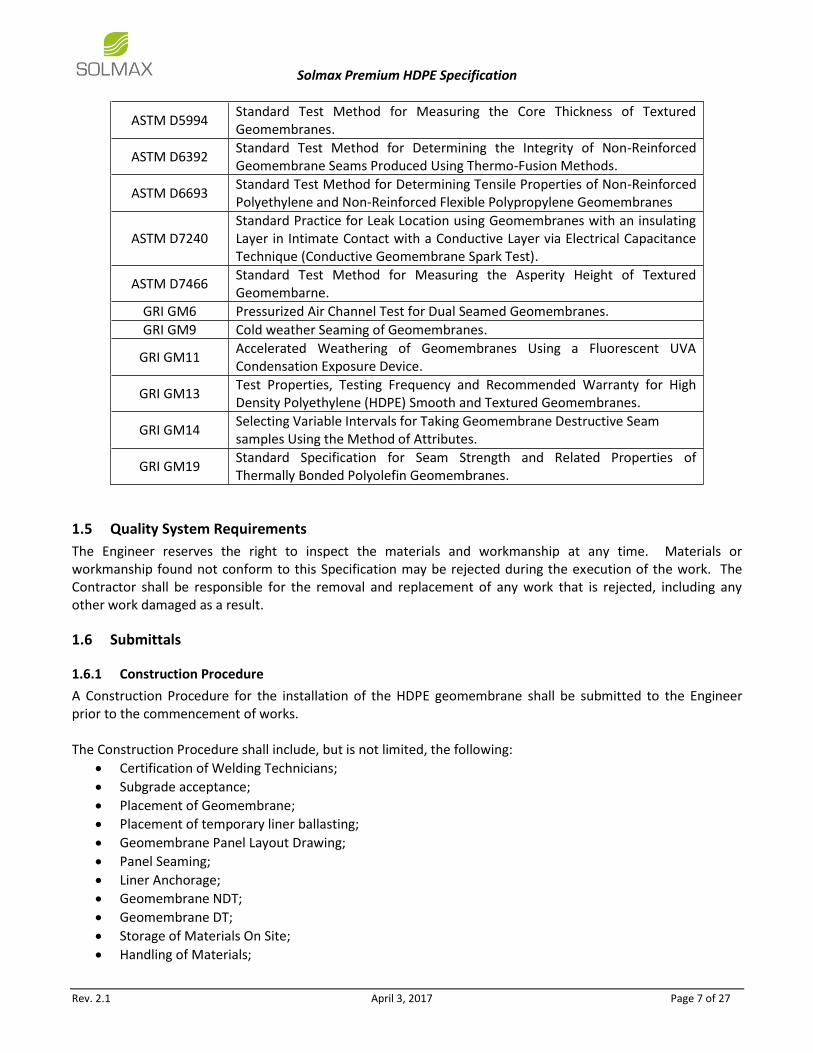
ASTM D5994 Standard Test Method for Measuring the Core Thickness of Textured Geomembranes.
ASTM D6392 Standard Test Method for Determining the Integrity of Non-Reinforced Geomembrane Seams Produced Using Thermo-Fusion Methods.
ASTM D6693 Standard Test Method for Determining Tensile Properties of Non-Reinforced Polyethylene and Non-Reinforced Flexible Polypropylene Geomembranes
ASTM D7240 Standard Practice for Leak Location using Geomembranes with an insulating Layer in Intimate Contact with a Conductive Layer via Electrical Capacitance Technique (Conductive Geomembrane Spark Test).
ASTM D7466 Standard Test Method for Measuring the Asperity Height of Textured Geomembarne.
GRI GM6 Pressurized Air Channel Test for Dual Seamed Geomembranes.
GRI GM9 Cold weather Seaming of Geomembranes.
GRI GM11 Accelerated Weathering of Geomembranes Using a Fluorescent UVA Condensation Exposure Device.
GRI GM13 Test Properties, Testing Frequency and Recommended Warranty for High Density Polyethylene (HDPE) Smooth and Textured Geomembranes.
GRI GM14 Selecting Variable Intervals for Taking Geomembrane Destructive Seam samples Using the Method of Attributes.
GRI GM19 Standard Specification for Seam Strength and Related Properties of Thermally Bonded Polyolefin Geomembranes.
1.5 Quality System Requirements
The Engineer reserves the right to inspect the materials and workmanship at any time. Materials or workmanship found not conform to this Specification may be rejected during the execution of the work. The Contractor shall be responsible for the removal and replacement of any work that is rejected, including any other work damaged as a result.
1.6 Submittals
1.6.1 Construction Procedure
A Construction Procedure for the installation of the HDPE geomembrane shall be submitted to the Engineer prior to the commencement of works. The Construction Procedure shall include, but is not limited, the following:
Certification of Welding Technicians;
Subgrade acceptance;
Placement of Geomembrane;
Placement of temporary liner ballasting;
Geomembrane Panel Layout Drawing;
Panel Seaming;
Liner Anchorage;
Geomembrane NDT;
Geomembrane DT;
Storage of Materials On Site;
Handling of Materials;

Solmax Premium HDPE Specification
Rev. 2.1 April 3, 2017 Page 8 of 27
Disposal of Excess Materials;
Product Identification and Traceability;
Inspection and Test Plans.
1.6.2 Panel Layout Drawing
The Geomembrane Installer shall prepare geomembrane panel layout drawings allocating a logical sequence of numbers to panel and seams. Three copies shall be submitted to the Engineer as part of the overall Construction Procedure for review and approval. The panel layout should minimize the number of panels and the length of seams. Seams shall be oriented perpendicular to the batter slopes and not across the batter slopes wherever practical. No horizontal seam should be located within 1.5m of a batter toe line. Horizontal seams should be staggered across each width of roll. The panel layout may be varied in the field from that shown on the drawings only with the approval of the Engineer in writing. In accordance with the Construction Procedure (Section 1.6.1: Construction Procedure), the following shall be included in the panel layout drawings:
Proposed Starting Position for the placement of the HDPE Geomembrane;
Panel Numbering System;
Panel Diagram (of Suitable Scale); o Panel Layout o Panel Dimensions
Relevant Experience of Geomembrane Installer;
1.6.3 Manufacturer QC Documentation
All materials must strictly comply with the requirements of this Specification. For all materials, a Manufacturer QC documentation shall be provided to the Engineer before the materials are to be installed. The Manufacturer QC documentation shall include, but is not limited to, the following:
Roll Number;
Resin Lot;
Product Code;
Manufacturing Date;
Roll Length;
Roll Test Data Report; o Average Thickness (ASTM D5994) o Minimum Thickness (ASTM D5994) o Asperity Height (ASTM D7466) o Tensile Properties (ASTM D6693) o Tear Resistance (ASTM D1004) o Puncture Resistance (ASTM D4833) o Density (ASTM D1505) o Carbon Black Content (ASTM D4218) o Standard Oxidative Induction Time (ASTM D3895) or o High Pressure Oxidative Induction Time (ASTM D5885) o Oven Aging at 85°C, % Retained after 90days (ASTM D3895 / ASTM D5885) o UV Resistance, % Retained after 1600hours (GRI GM11 / ASTM D5885)

Solmax Premium HDPE Specification
Rev. 2.1 April 3, 2017 Page 9 of 27
1.7 Qualifications
1.7.1 Manufacturer Qualifications
The Geomembrane shall be manufactured by Solmax International Inc. or approved equal. The Manufacturer shall have manufactured a minimum of 10,000,000 ft2 of polyethylene geomembranes during the past year. The Manufacturer shall carry the following certifications:
ISO 9001
GAI-LAP
1.7.2 Geomembrane Installer Qualifications
Installation shall be performed according to IAGI Installation Specification. The Geomembrane Installer shall have installed a minimum of 10 projects involving a total of 5,000,000 ft2
of HDPE or similar geomembrane product during the last 3 years. The Installation Supervisor shall have installed or supervised the installation and seaming of a minimum of 10 projects involving a total of 5,000,000 ft2
of HDPE or similar geomembrane product. The Installation Supervisor shall have worked in a similar capacity on projects similar in size and complexity to the project described in the Contract Documents. The Geomembrane Installer shall provide a minimum of one Master Seamer for work on the project. The Master Seamer must have completed a minimum of 3,000,000 ft2 of geomembranes seaming work using the type of seaming apparatus proposed for the use on this Project.

Solmax Premium HDPE Specification
Rev. 2.1 April 3, 2017 Page 10 of 27
2. Materials
2.1 General
All materials must strictly comply with the requirements of this Specification. For all materials, a Technical Data Sheet with the required testing shall be provided to and approved by the Engineer before the materials are to be installed. The Contractor shall allow sufficient time for the Engineer to review the certified test results provided to not impact the geomembrane delivery schedule. Materials shall be protected against solar radiation, mud, dirt, dust, puncture, cutting or any other damaging or deleterious conditions. Materials and equipment damaged prior to, and or during installation shall not be used and must be replaced at the Contractor’s expense. Production samples of materials shall be provided to the Engineer and will be held throughout the period of the contract for the purpose of providing a reference against which all subsequent items may be gauged for compliance with this Specification. The HDPE geomembrane shall be a new, first-quality product designed specifically for the purpose of hydraulic containment and of the thickness specified. The membrane shall be uniform, free of holes, blisters, bubbles, gels, nicks, cuts, undispersed raw materials, or any sign of contamination by foreign matter.
2.2 Geomembrane Material
The geomembranes shall be comprised of High Density Polyethylene (HDPE) and shall meet the required physical, mechanical and endurance properties shown in the product Technical Data Sheet in Table 5 (a), (b) and (c) (below).

Solmax Premium HDPE Specification
Rev. 2.1 April 3, 2017 Page 11 of 27
Table 5(a) – Black Premium HDPE Geomembrane (Smooth) Technical Properties
*The Premium HDPE geomembranes roll can be supplied in 22.3 ft Width.
Notes: (1) Testing Frequency based on standard roll dimensions and one batch is approximately 180,000 lbs (or one railcar) (2) Machine Direction (MD) and Cross Machine Direction (XMD or TD) average value should be on the basis of 5 specimens each direction. (8) Correlation table is available for ASTM D792 vs ASTM D1505. Both methods give the same results. (9) Correlation table is available for ASTM D1603 vs ASTM D4218. Both methods give the same results.
*All values are nominal test results, except when specified as minimum or maximum. *The information contained herein is provided for reference purposes only and is not intended as a warranty of guarantee. Final determination of suitability for use contemplated is the sole responsibility of the user. SOLMAX assumes no liability in connection with the use of this information. Solmax is not a design professional and has not performed any design services to determine if Solmax’s goods comply with any project plans or specifications, or with the application or use Solmax’s goods to any particular system, project, purpose, installation or specification.
*Please select the suitable and up to date Technical Data Sheet from Solmax’s website or refer to Solmax’s sales representative.

Solmax Premium HDPE Specification
Rev. 2.1 April 3, 2017 Page 12 of 27
Table 5(b) - Premium HDPE Geomembrane (Single Textured) Technical Properties
*The Premium HDPE geomembranes roll can be supplied in 22.3 ft Width.
Notes: (1) Testing Frequency based on standard roll dimensions and one batch is approximately 180,000 lbs (or one railcar) (2) Machine Direction (MD) and Cross Machine Direction (XMD or TD) average value should be on the basis of 5 specimens each direction. (3) ASTM D7466 is identical to GRI-GM12. (8) Correlation table is available for ASTM D792 vs ASTM D1505. Both methods give the same results. (9) Correlation table is available for ASTM D1603 vs ASTM D4218. Both methods give the same results.
*All values are nominal test results, except when specified as minimum or maximum. *The information contained herein is provided for reference purposes only and is not intended as a warranty of guarantee. Final determination of suitability for use contemplated is the sole responsibility of the user. SOLMAX assumes no liability in connection with the use of this information. Solmax is not a design professional and has not performed any design services to determine if Solmax’s goods comply with any project plans or specifications, or with the application or use Solmax’s goods to any particular system, project, purpose, installation or specification.
*Please select the suitable and up to date Technical Data Sheet from Solmax’s website or refer to Solmax’s sales representative.

Solmax Premium HDPE Specification
Rev. 2.1 April 3, 2017 Page 13 of 27
Table 5(c) - Premium HDPE Geomembrane (Textured) Technical Properties
*The Premium HDPE geomembranes roll can be supplied in 22.3 ft Width.
Notes: (1) Testing Frequency based on standard roll dimensions and one batch is approximately 180,000 lbs (or one railcar) (2) Machine Direction (MD) and Cross Machine Direction (XMD or TD) average value should be on the basis of 5 specimens each direction. (3) ASTM D7466 is identical to GRI-GM12. (8) Correlation table is available for ASTM D792 vs ASTM D1505. Both methods give the same results. (9) Correlation table is available for ASTM D1603 vs ASTM D4218. Both methods give the same results.
*All values are nominal test results, except when specified as minimum or maximum. *The information contained herein is provided for reference purposes only and is not intended as a warranty of guarantee. Final determination of suitability for use contemplated is the sole responsibility of the user. SOLMAX assumes no liability in connection with the use of this information. Solmax is not a design professional and has not performed any design services to determine if Solmax’s goods comply with any project plans or specifications, or with the application or use Solmax’s goods to any particular system, project, purpose, installation or specification.
*Please select the suitable and up to date Technical Data Sheet from Solmax’s website or refer to Solmax’s sales representative.

Solmax Premium HDPE Specification
Rev. 2.1 April 3, 2017 Page 14 of 27
2.3 Geomembrane Manufacturing Quality Control
The geomembrane shall be monitored throughout the manufacturing process for product integrity and consistency. The manufacturer shall test rolls in accordance with Table 5 (a), (b) and (c) (above) with results showing conformance with the required physical properties listed in Table 5 (a), (b) and (c) (above). Certified test results shall be submitted to and approved by the Engineer before the HDPE geomembrane rolls are to be installed from the manufacturing plant. The Geomembrane Installer shall allow sufficient time for the Engineer to review the certified test results provided to not impact the geomembrane delivery schedule. The Geomembrane Installer shall submit a list which indicates date of production, resin batch number, manufacturing line number and identification number and square feet of each geomembranes roll. Rolls shall be listed in the order of production with the status of the roll (rejected or approved for shipment). All rolls shall be included in the list whether or not approved for shipment. Any roll(s) that do not meet the required physical properties or have not been tested at the required frequency (Table 5(a), (b) and (c)) shall be rejected and removed from site.
2.4 HDPE Resin
Resin used in the manufacture of HDPE geomembranes shall be first quality single source, compounded polyethylene resin manufactured specifically for the purpose of producing HDPE geomembranes. Reclaimed polymer shall not be added to the resin. The manufacturer may rework edge trim from the roll being produced. Edge trim shall be returned immediately to the process but shall not exceed 10% of the total resin required. Edge trim which has been stored or sourced from other manufacturing plants shall not be recycled. The manufacturer shall sample and test for the properties listed in Table 6 (below) per batch resin. Certified test results shall be submitted to and approved by the Engineer before the HDPE geomembrane rolls are to be installed. The Geomembrane Installer shall allow sufficient time for the Engineer to review the certified test results provided to not impact the geomembrane delivery schedule.
Table 6 - Resin Physical Properties
Test Property Test Method Unit Requirement
Density(1) ASTM D1505 g/cm3 ≥ 0.932
Melt Flow Index ASTM D1238 g/10 min. ≤ 1.00 Notes:
(1) Base resin density without carbon black added.
2.5 Extrudate Material
The extrudate rod or bead shall be high quality polyethylene and shall be of the same formulation as the resin used to produce the geomembranes. All additives shall be thoroughly dispersed throughout the extrudate rod or bead. There shall be no contamination by foreign matter in the extrudate rod or bead.
2.6 Roll Identification
Geomembrane shall be supplied in rolls of width accordance to the product Technical Data Sheet in Table 5(a), (b) and (c). The rolls supplied should not allow any longitudinal seams. As a minimum, each roll shall be labeled as follows:
Roll Number;
Name of Manufacturer;

Solmax Premium HDPE Specification
Rev. 2.1 April 3, 2017 Page 15 of 27
Batch Number of Raw Material;
Date of Manufacture;
Material Thickness;
Roll Length and Area;
Product Type and Grade. Rolls will need to have permanent marking every 16 feet along the smooth edges that include, as a minimum, the following information:
Roll Number;
Distance from start of the roll (in feet or meters).
2.7 Delivery
Rolls of geomembrane will be prepared to ship by appropriate means to prevent damage to the material and to facilitate off-loading.
2.8 Storage
The on-site storage location for geomembrane rolls, provided by the Contractor to protect the geomembranes from puncture, abrasion and excessive dirt and moisture should have the following characteristics:
Level (no wooden pallets);
Smooth;
Dry;
Protected from theft and vandalism;
Adjacent to the area to be lined. The rolls shall be handled and stored with care to prevent any damage to the geomembrane. During the transport of the material from the manufacturing plant to site and storage of the geomembrane rolls on site, the geomembrane shall not be stacked higher than 3 rolls high.
2.9 Handling
Materials are to be handled so as to prevent damage.
2.10 Samples
The Contractor shall submit samples of the geomembrane material and field seams to the Engineer for approval prior to the start of construction. The Contractor shall submit 8.5’’x 11’’ samples of geomembrane materials which have been made in conformance with this Specification.
2.11 Geomembrane Warranty
The Contractor shall provide warranties for the geomembrane manufacturing and geomembrane installation in accordance.
2.11.1 Material Warranty
The geomembrane manufacturer shall furnish a written geomembrane warranty, which warrants the geomembrane material for a minimum of five (5) years from the date of installation and final acceptance of the geomembrane. The warranty shall be against manufacturing defects and workmanship. The warranty shall be limited to replacement of material only and shall be pro-rated.
Solmax Premium HDPE Specification
Rev. 2.1 April 3, 2017 Page 16 of 27
2.11.2 Installer Warranty
The Geomembrane Installer shall guarantee the geomembranes installation against defects in the installation and workmanship for one (1) year, commencing with the date of final acceptance of the geomembrane. A written geomembrane warranty will be required.
Solmax Premium HDPE Specification
Rev. 2.1 April 3, 2017 Page 17 of 27
3. Geomembrane Subgrade Preparation
3.1 Subgrade Preparation
The Geoembrane Installer shall ensure that all surfaces to be lined including corners and around penetrations shall be finished smooth and free of rocks, stones, sticks, roots, sharp objects and debris of any kind or any object which may damage the geomembrane in accordance with Specification [Specification #]. The surface is to provide a firm unyielding compacted subgrade for the geomembrane. All desiccation cracking shall be repaired by the Contractor to the satisfaction of the Engineer. Where a suitable surface cannot be achieved by treatment of in-situ material, an imported smoothing fine course shall be placed. The smoothing fine course shall consist of sandy clay which shall be free of organic matter and coarse or sharp particles. The smoothing course shall be the minimum thickness necessary to maintain 6’’ minimum cover over irregularities or protrusions in the sub-grade formation unless shown otherwise on the Drawings. The surface shall be watered and rolled with a smooth steel drum roller to obtain a smooth uniform finish. The Geomembrane Installer shall provide daily written subgrade acceptance certifications to the Engineer for the surface to be covered by the geomembranes in that day’s operation. The surface shall be maintained in a manner, during installation, to ensure subgrade stability. All subgrade damaged by construction equipment and deemed unsuitable for geomembranes deployment, in the opinion of the Engineer, shall be repaired prior to placement of the geomembranes. All repairs shall be approved by the Engineer. Surfaces to be lined shall be flat on any plane within ± 2’’ vertical tolerance in any area of 100 ft2. All intersections between planes shall be made along straight lines.
3.2 Subgrade Maintenance
Where surface finishing is completed ahead of geomembrane installation, the surface shall be maintained until immediately prior to geomembrane installation. This surface will need to be re-inspected again by the Engineer and approved prior to installation of the geomembrane. Sufficient equipment shall remain on the site until and during installation to enable reinstatement of the surface in the event of damage due to inclement weather or desiccation cracking. Any reinstatement work shall be at the expense of the Contractor. The Engineer reserves the right to instruct the Contractor to perform remedial work to satisfy the criteria.

Solmax Premium HDPE Specification
Rev. 2.1 April 3, 2017 Page 18 of 27
4. Geomembrane Installation
4.1 General
Geomembrane installation shall be performed in accordance with the International Association of Geosynthetic Installers (IAGI) HDPE Geomembrane Installation Specification. Where there is discrepancy between the IAGI HDPE Geomembrane Installation Specification and this Specification, this Specification shall govern. Rolls of geomembrane shall be handled and securely stored to prevent damage prior to installation. Geomembrane shall be unrolled in a controlled manner directly into the final position. The method of unrolling shall not cause scratches or crimps in the material, nor shall it disrupt the integrity of the finished sub-grade. The geomembrane shall be placed in a relaxed state such that the material can respond to thermal changes without excessive buckling, wrinkling or tensioning. Slack shall be included in the geomembrane on the batter side of the tie-in seam along the toe of all internal slopes. The included slack at the tie-in seam will minimize tension on the tie-in seam due to contraction of the geomembrane at temperatures cooler than ambient during installation. This induced slack shall vary in height based on the ambient air temperature as given in Table 7 (below).
Table 7 - Induced Slack Height at Varying Ambient Temperatures
Ambient Air Temperature (°F) Slack Height (inches)
32-40 1
40-50 2
50-60 3
60-70 4
70-80 5
80-90 6
90-100 7
100-110 8
For material temperatures between 5°F and 32°F, the deployment and seaming will be performed in accordance with GRI GM9. No geomembranes material shall be unrolled or deployed if the material temperatures are lower than 5°F, unless otherwise approved in writing by the Engineer. Only the quantity of geomembranes that will be anchored and seamed together in one day shall be deployed. In general, seams shall be orientated parallel to the line of maximum slope. In corners and odd shaped geometric locations, the total length of the field seam shall be minimized. Seams shall not be located at low points in the subgrade unless geometry requires seaming at such locations as approved by the Engineer. All HDPE panels that are to be welded together shall be manufactured by the same geomembrane manufacturer, made from the same resin type and made using the same formulation. Adjacent HDPE panels that do not satisfy all of these requirements shall not be welded together. Any panels welded together that violate any of these criteria shall be rejected and removed from site at the Geomembrane Installer’s expense. The geomembranes shall not be allowed to “bridge” over voids or low areas in the subgrade. The geomembranes shall rest in intimate contact with the subgrade.

Solmax Premium HDPE Specification
Rev. 2.1 April 3, 2017 Page 19 of 27
Temporary ballasting such as sand bags or tires shall be placed on the geomembrane to prevent wind damage during and after installation. It should be noted that this temporary ballasting shall be of a suitable construction to prevent against damage of the geomembrane. The Contractor shall be required to ensure that the spacing of these sand bags / tires are appropriately designed (this could include tying the sand bags / tires together in a horizontal and vertical direction) to prevent against uplift and potential damage of the geomembrane. Any geomembrane material that has been damaged as the result of the wind, in the opinion of the Engineer, shall be removed and replaced at the Contractor’s expense. All personnel working on the geomembrane surface shall wear soft-soled shoes, and shall not engage in any activity which may damage the geomembrane. Machinery, other than seam welding machinery or All-Terrain Vehicles (ATV) approved for use by the Engineer in writing, shall not be operated on the geomembrane. The use of ATVs for the deployment of the geomembrane will be allowed. For ATVs to be used, the Contractor must demonstrate that the ATV exerts a maximum allowable pressure on the ground surface (or geomembrane surface) of 8 psi. The maximum allowable pressure on the ground surface (or geomembrane surface) is influenced by the tread pattern of the tires on the ATV. The maximum allowable ground surface (or geomembrane surface) pressure is not the reading from a tire pressure gauge. The ATVs shall only be used to deploy rolls of geomembrane and shall not be used to transport personnel, equipment, sandbags or the like.
4.2 Seaming
4.2.1 General
Seaming of geomembranes shall be carried out strictly in accordance with the manufacturer’s written instructions and in accordance with GRI GM19. The contractor shall provide a complete description of the processes to be used, and shall identify the equipment proposed for accomplishing the seaming. No geomembranes material shall be seamed when the sheet temperature is below 5°F and above 170°F as measured by an infrared thermometer (or surface thermocouple), unless otherwise approved by the Engineer. For material temperatures between 5°F and 32°F, seaming shall be performed in accordance with GRI GM9.
4.2.2 Personnel
The Contractor shall nominate a Project Seam Welding Supervisor before commencing work and shall demonstrate that the Seam Welding Supervisor has a proven background in installation of lining systems and materials similar to those specified. All personnel employed in welding shall be competent and experienced in the use of the equipment. The Contractor shall ultimately be responsible for ensuring the quality assurance program is followed.
4.2.3 Seam Welding Equipment
Only specialized purpose-designed equipment approved by the Engineer shall be used. For long-run work, the machine shall be mounted on a carriage to operate at a controlled speed. In all cases, the temperature at the point of fusion shall be monitored and controlled with an interlock to the drive mechanism so that welding is stopped if the temperature falls outside the range at which satisfactory welding can be achieved.

Solmax Premium HDPE Specification
Rev. 2.1 April 3, 2017 Page 20 of 27
Where the welding procedure includes provision for heated extrudate to be incorporated in the weld, any degraded extrudate, which has been overheated or heated and cooled in the barrel, shall be purged with fresh material prior to the resumption of welding. Equipment shall be maintained on a regular basis to ensure efficient performance throughout. The field tensiometer shall have a current certificate of calibration in accordance with the manufacturer’s calibration recommendations.
4.2.4 Seam Strength Requirements
Each test specimen should fail in the parent material and not in the weld as demonstrated by test welds and destructive test samples in accordance with Section 5: Geomembrane Inspection & Testing. Breadth and depth of fusion between sheets shall be as required to meet these criteria. Where heated extrudate is included in the weld, the extrudate material after fusion shall be fully compatible physically and chemically with the geomembrane material. The geomembrane material shall not be overheated during welding such that crystallization, oxidation, perforation or degradation of the geomembrane occurs.
4.2.5 Weather Conditions
Welding shall not be commenced or continued during rain, fog, excessive winds, snowing, sleeting or hailing. Welding shall not be commenced or continued when ambient temperatures (as measure 3’ above the seam being welded) is outside the range of 5°F to 100°F. When ambient temperatures are between 5°F and 32°F, seaming shall be performed in accordance with GRI GM9. The seams adjacent to the corners of the ponds and the toe of the slopes shall be made during the coolest part of the day and shall not be made when the geomembrane is exposed to direct sunlight.
4.2.6 Geomembrane Preparation
The surface of the geomembrane to be welded shall be clean, dry and free from any foreign matter and contaminants, such as clay and sand.
4.2.7 Seam Lap
The minimum lap of adjacent geomembrane sheets shall be 6’’, unless specified as greater by the geomembrane manufacturer or the welding equipment supplier. Fishmouths, or excessive wrinkles at the seam overlap, shall be minimized. When necessary, cut along the ridge of the wrinkles back into the panel to create a flat overlap. The cut shall be terminated with a keyhole cut (nominal 0.5’’ diameter hole) so as to minimize crack/tear propagation. The overlay shall subsequently be seamed. The keyhole cut shall be patched with an oval or round patch, of the same base geomembrane material extending a minimum of 6’’ beyond the cut in all directions.
4.2.8 Fusion Welding (Primary Welds)
Seam welding of HDPE geomembranes shall be accomplished primarily by fusion welding using either a hot wedge or hot air welder. Geomembrane surface area to be fusion welded must be cleaned from dust, mud, debris and shall be protected against moisture build-up between sheets.

Solmax Premium HDPE Specification
Rev. 2.1 April 3, 2017 Page 21 of 27
The seam shall consist of a double weld produced by surface fusion with an air gap between. Pressure nipping rollers shall press the molten surfaces together immediately behind the hot air or hot wedge welder to complete the weld.
4.2.9 Extrusion Welding (Secondary Welds)
Extrusion welding shall only be used where fusion welding is not possible, such as at pipe penetrations, patches, repairs, and short runs of seams (less than a roll width). Geomembrane surface area to be extrusion welded must be cleaned by using disc grinder or equivalent to remove the oxidized layers and dirt. The leading edge of the upper geomembrane needs to be beveled or tapered to a 45° angle and the bottom geomembrane grind marks shall be about 5% of the liner thickness. Extrusion welding shall be achieved by fusion of an extrudate to the top surface of both sheets at the lap. The depth and width of engagement of the extrudate shall be as required to achieve the strength requirements. The means of deposition of the extrudate shall provide for full integration with the surface of the sheets, so that the weld becomes homogeneous with the geomembrane.
4.2.10 Connections at Penetration and to Structures
Connections to geomembrane penetrations and adjoining structures shall be made in accordance with the details shown on the construction drawings. Connections shall be at least equivalent in strength to the normal lap seams and the security of containment shall not be diminished. Local stresses in the geomembrane at connections shall be minimized. Penetrations shall be constructed from the base geomembranes material, flat stock, prefabricated boots and accessories as shown in the construction drawings.
4.3 Geomembrane Anchorage
Anchor trenches shall be excavated in accordance with the details on the construction drawings. The anchor trenches shall be kept well drained to avoid softening during rain periods and maintained so as to not dry, desiccate and crack. In accordance with [Specification #], the Contractor shall seek approval from the Engineer prior to the commencement of anchor trench backfilling. Once the anchor trench is ready to be backfilled, it shall be backfilled in early morning when the geomembrane is at maximum contraction. Backfilling shall be carried out in planned, logical sequence to avoid overstressing of the geomembrane. The front edge of the anchor trench will be rounded, with no sharp stones that might damage the liner.
4.4 Cleaning Up
On completion of the work on site, the Contractor shall clean up and leave the whole area to the satisfaction of the Engineer.

Solmax Premium HDPE Specification
Rev. 2.1 April 3, 2017 Page 22 of 27
5. Geomembrane Inspection, Testing & Repair All areas found to be defective shall be repaired at the expense of the Geomembrane Installer. The Engineer shall be notified of defective areas prior to the repair taking place. The Geomembrane Installer shall ensure a plan is marked up showing the locations of repairs made and the type of repair made. The Geomembrane Installer shall submit a marked up drawing showing the locations of the repairs to the Engineer for review and approval.
5.1 Visual Inspections
The entire surface of every sheet of geomembrane material shall be inspected by the Geomembrane Installer during placing to identify any tears, abrasions, indentations, cracks, thin areas, or other defects. Any defects such as holes, tears, blisters, lamination, undispersed raw materials or visible non-uniformity or contamination by foreign matter which in the opinion of the Engineer is detrimental to the long service life required of the membrane geomembrane, shall be grounds for rejection of the membrane geomembrane material. Where additional faults are found, the Engineer reserves the right to reject the roll. The Contractor shall replace any rejected rolls and repair any defects to the Engineer’s satisfaction at the Geomembrane Installer’s expense.
5.1.1 Geomembrane Visual Inspections
Following the installation of the geomembrane, a detailed visual inspection of the primary geomembrane surface shall be performed by the Engineer (accompanied by the Geomembrane Installer), to identify any defects in the geomembrane surface caused during installation. Prior to performing the survey, a survey grid shall be determined to ensure that the visual survey is performed across 100% of the geomembrane surface.
5.2 Seam Testing
All geomembrane weld seams shall be subjected to both non-destructive and destructive field testing. Additionally, representative samples of field seams shall be taken for laboratory testing by an independent, appropriately qualified geosynthetic testing laboratory. The tests in this Section shall be carried out at the specified frequencies. Testing of each length of seam shall be carried out within 48 hours of its completion. The acceptance criteria for peel and shear strength testing shall be in accordance with GRI GM19.
5.2.1 Test Welds (In Field)
Test seams shall be made by each welding technician and tested in accordance with ASTM D6392 at the beginning of each seam period. Test seaming shall be performed under the same conditions and with the same equipment and operator combination as production seams. The test seam shall be approximately 6 feet long for fusion welding and 3 feet long for extrusion welding with the seam centered lengthwise. At a minimum, trial welds shall be made by each technician as follows:
Prior to commencement of each shift;
One time every 4 hour thereafter;
Solmax Premium HDPE Specification
Rev. 2.1 April 3, 2017 Page 23 of 27
Following any break in operation;
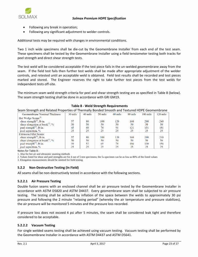
Following any significant adjustment to welder controls. Additional tests may be required with changes in environmental conditions. Two 1 inch wide specimens shall be die-cut by the Geomembrane Installer from each end of the test seam. These specimens shall be tested by the Geomembrane Installer using a field tensiometer testing both tracks for peel strength and direct shear strength tests. The test weld will be considered acceptable if the test piece fails in the un-welded geomembrane away from the seam. If the field test fails then further test welds shall be made after appropriate adjustment of the welder controls, and retested until an acceptable weld is obtained. Field test results shall be recorded and test pieces marked and stored. The Engineer reserves the right to take further test pieces from the test welds for independent tests off-site. The minimum seam weld strength criteria for peel and shear strength testing are as specified in Table 8 (below). The seam strength testing shall be done in accordance with GRI GM19.
Table 8 - Weld Strength Requirements Seam Strength and Related Properties of Thermally Bonded Smooth and Textured HDPE Geomembrane
Notes for Table 8 : 1. Also for hot air and ultrasonic seaming methods 2. Values listed for shear and peel strengths are for 4 out of 5 test specimens; the 5th specimen can be as low as 80% of the listed values
3. Elongation measurements should be omitted for field testing
5.2.2 Non-Destructive Testing (In Field)
All seams shall be non-destructively tested in accordance with the following sections.
5.2.2.1 Air Pressure Testing
Double fusion seams with an enclosed channel shall be air pressure tested by the Geomembrane Installer in accordance with ASTM D5820 and ASTM D4437. Every geomembrane seam shall be subjected to air pressure testing. The testing shall be achieved by inflation of the space between the welds to approximately 30 psi pressure and following the 2 minute “relaxing period” (whereby the air temperature and pressure stabilizes), the air pressure will be monitored 5 minutes and the pressure loss recorded. If pressure loss does not exceed 4 psi after 5 minutes, the seam shall be considered leak tight and therefore considered to be acceptable.
5.2.2.2 Vacuum Testing
For single welded seams testing shall be achieved using vacuum testing. Vacuum testing shall be performed by the Geomembrane Installer in accordance with ASTM D4437 and ASTM D5641.

Solmax Premium HDPE Specification
Rev. 2.1 April 3, 2017 Page 24 of 27
The Vacuum pump shall be charged and the tank pressure adjusted to approximately 5 psi. If no bubbles appear while the vacuum is held for 5 seconds, then the seam is satisfactory.
5.2.3 Destructive Testing (In Field & In Laboratory)
Samples for destructive testing shall be taken from finished seams at locations as directed by the Engineer. A sampling frequency of one sample per 500 feet of seam length shall be used. The sample shall be taken by the Geomembrane Installer from a location specified by the Engineer. Each sample shall be 3 feet long, parallel to the seam by 1 foot wide, with the seam central in width. The sample shall be cut into three equal sections distributed as indicated in Table 9 (below).
Table 9 - Destructive Test Sample Allocation
Sample Section No. Sample Allocation Allocation Description
1 Field Testing Seam Strength Testing
2 Laboratory Seam Strength Testing
3 Engineer Record Section
For field testing, the Geomembrane Installer shall cut 10 identical 1 inch wide replicate specimens from their sample (Table 9, Sample Section No. 1). The Geomembrane Installer shall test five (5) specimens for seam shear strength and five (5) for peel strength. Peel tests shall be performed on both inside and outside weld tracks. To be acceptable, 4 of 5 test specimens must pass the stated criteria in Table 9 (above) with less than 25% separation. If 4 of 5 specimens pass, the sample qualifies for testing by the testing laboratory. The preparation of the sample and field testing by the Geomembrane Installer shall be witnessed by an Independent Construction Quality Assurance (CQA) firm representative. If any samples fail field testing, additional samples shall be taken to define the extent of sub-standard seam. Destructive testing of the seams must be carried out as the seams are welded together on a continuous basis. Destructive testing shall not be conducted at the end of the geomembrane installation. For laboratory testing, the laboratory shall cut 10 identical 1 inch wide replicate specimens from their sample (Table 9, Sample Section No. 2). The laboratory shall test five (5) specimens for seam shear strength and five (5) for peel strength. The laboratory shall test the samples in accordance with GRI GM19 and report the results to the Contractor and the Engineer simultaneously. The third sample section (Table 9, Sample Section No. 3) shall be submitted to the Engineer for record keeping. The third sample section shall not be used by the Geomembrane Installer to confirm marginally failing test results obtained from their sample. For field seams, if a laboratory test fails, that shall be considered an indicator of the possible inadequacy of the entire seamed length corresponding to the test sample. Additional destructive test portions shall then be taken by the Geomembrane Installer from locations 10 feet on either side of the failed sample (c/c by sample). Field and Laboratory testing shall be conducted on these verification samples. Passing tests shall be an indicator of adequate seams. Failing tests shall be an indicator of non-adequate seams and all seams represented by the destructive test locations shall be repaired with a cap-strip extrusion welded to all sides of the capped area. All cap-strip seams shall be non-destructively vacuum box tested until adequacy of the seams is achieved. Cap strip seams exceeding 165 feet in length shall be destructively tested.

Solmax Premium HDPE Specification
Rev. 2.1 April 3, 2017 Page 25 of 27
5.3 Geomembrane Defects
5.3.1 Identification of Defects
Panels and seams shall be inspected by the Geomembrane Installer, Contractor and Engineer during and after panel deployment to identify all defects, including holes, blisters, undispersed raw materials and signs of contamination by foreign matter.
5.3.2 Evaluation of Defects
Each suspect location on the geomembrane (both in geomembranes seam and non-seam areas) shall be non-destructively tested using one of the methods described in Section 5.2.2: Non-Destructive Testing. Each location which fails non-destructive testing shall be marked, numbered, measured and posted on the daily “installation” drawings and subsequently repaired. If a destructive sample fails the field or laboratory test, the Geomembrane Installer shall repair the seam between the two nearest passed locations on both sides of the failed destructive sample location.
5.3.3 Wrinkles
Any wrinkles that can fold over shall be repaired either by cutting out excess material or, if possible, allowing the geomembrane to contract as the temperature decreases. In no case shall material be placed over the geomembrane that could result in the geomembrane folding. All folded geomembrane shall be removed. No material shall be placed in areas where the geomembrane is not in contact with the supporting subgrade.
5.4 Geomembrane Repair
5.4.1 Geomembrane Repair Procedures
Any portion of the geomembrane with a flaw or that fails a non-destructive test shall be repaired by one of the following methods:
Patching for holes, defects or tears 0.5 inch or larger in diameter or length – used to repair large holes, tears, large panel defects, and destructive sample locations that are less than 20ft2 (total area);
Extrusion – used to repair relatively small defects in panels and seams, but not greater than 0.5 inch in length;
Capping – used to repair failed welds or geomembrane seams where welds cannot be non-destructively tested;
Removal – used to replace areas with large defects where the preceding methods are not appropriate. Also used to remove excess material (wrinkles) from the installed geomembrane.
Once the repair has been completed, further non-destructive or destructive testing shall be carried out to ensure the repairs are completed to the requirements of this Specification.
5.4.2 Verification of Seam Repairs
Each repair shall be non-destructively tested using either vacuum box or spark testing methods. Tests which pass the non-destructive test shall be taken as an indication of a successful repair. Failed tests shall be re-seamed and retested until a passing test results. The number, date, location, technician and test outcome of each patch shall be recorded.

Solmax Premium HDPE Specification
Rev. 2.1 April 3, 2017 Page 26 of 27
5.5 Testing & Inspection Records
Full records of geomembrane testing and inspection shall be submitted progressively to the Engineer, as the work proceeds. Final completion will not be certified until all records have been submitted and approved by the Engineer. Records shall include, but not limited to, the following:
Contractor’s panel layout drawing showing panel numbers and seam numbers, to be marked up progressively with the roll number used for each panel, and with the locations of samples taken for destructive testing;
Manufacturer’s roll production test reports for all rolls used in the work;
Subgrade certification reports;
Daily vacuum box or seam inflation test reports referenced to seam numbers;
Daily test weld field test reports referenced to seam numbers, equipment identification, and operator, and including weather and temperature conditions and any adjustments to equipment controls;
Destructive test field report and record of submission for laboratory testing referenced to seam number;
Laboratory test reports to be available within two weeks of testing;
Record drawing indicating geomembrane seam locations, destructive test locations, cap strip locations, patches and all repairs for the geomembrane system.

Solmax Premium HDPE Specification
Rev. 2.1 April 3, 2017 Page 27 of 27
6. Geomembrane Completion The Geomembrane Installer shall undertake post installation testing of geomembrane as soon as practical after installation. Installation and material defects detected by post installation testing shall be covered under the Installation warranty and shall be repaired to the satisfaction of the Engineer.
6.1 Geomembrane Completion Acceptance Criteria
Upon completion of the geomembrane completion phase (complete with repair and re-testing of leaks), the geomembrane installation shall be deemed as substantially complete and handover shall be approved by the Engineer. Following handover, leakage rates shall be monitored by the Owner during first filling for the presence of leakage. If leakage is detected within the first year, the installer shall re-mobilize on-site and locate and repair the leaks per the requirements of Section 2.11.2: Geomembrane Installer Warranty. The Engineer shall release the work as being complete upon receipt and approval of the following:
Checks on application and final finish;
The installation of HDPE geomembranes has been completed and signed off;
Repairs to defects have been completed;
Site has been left clean with no litter;
All required documentation has been provided to the Engineer in accordance with Section 5.5: Testing & Inspection Records.
End of Specification