specifications -...
TRANSCRIPT

TABLE SAW250mm (10") 1500WINSTRUCTION MANUALSPECIFICATIONSMotor: 1500W (S6 40%)Input: 230-240V ~ 50HzNo Load Speed: 5,700/minBlade: Ø250mm x Ø30 x 2.4mmBevel Angle: 0-45° leftDepth Of Cut: 0-73mmMax. Cutting Capacity: Bevel 90°: 73mm Bevel 45°: 60mmTable Size: 640 x 446mmWith Side Ext.: 640 x 946mmRear Extension: 440 x 326mmDust Port: Ø35mm I/D / Ø40 O/DWeight: 25kg
TSF-1210
WHAT’S IN THE BOX
ozito.com.au
Base Frame Legs x 4, Cross Struts x 4, Feet x 4
Blade Guard & Dust Extractor Hose with Clip
Sliding Mitre Gauge
Push Stick, Spanners x 2,Stabilising Brackets x 2
Table Extensions x 3Support Struts x 6
42 x Bolts & Washers, 34 x Nuts
Rip Fence

3
ONLINE MANUALScan this QR Code with your mobile device to take you to the online manual.
1 Saw table
2 Rip fence
3 Rip fence lever
4 Guide rail
5 Base frame
6 Sliding mitre gauge
7 Table insert
8 Dust extractor hose
9 Blade guard
10 Push stick
11 Saw blade
12 Riving knife
13 Extractor adapter
14 ON/OFF switch
15 Blade bevel adjustment
16 Blade height adjustment
17 Bevel lock lever
TABLE SAW
KNOW YOUR PRODUCT
54 6 8
1. ASSEMBLY
For detailed assembly instruction see Assembly Manual.
SETUP & PREPARATION
32
9 14
7
Fitting the blade guard1. Mount the blade guard on
the riving knife so that the screw fits through the hole in the riving knife.
2. Do not tighten the screw too far – the blade guard must be able to move freely.
IMpOrTANT! ThE BLAdE gUArd MUST ALWAyS BE LOWErEd OvEr ThE WOrkpIEcE BEFOrE yOU BEgIN TO cUT.
IMpOrTANT! BEFOrE cLEANINg yOUr TABLE SAW Or cArryINg OUT ANy MAINTENANcE prOcEdUrE, MAkE SUrE ThAT ThE MOTOr IS OFF ANd ThE TOOL dIScONNEcTEd FrOM ThE pOWEr SUppLy TO prEvENT AccIdENTAL STArTINg.
changing the table insert 1. To prevent increased likelihood
of injury the table insert should be changed whenever it is worn or damaged.
2. Lower the blade then remove the blade guard.
3. Remove the countersunk head screw.
4. Take out the worn table insert.
5. To fit the replacement table insert, proceed in reverse order.
SETUP & PREPARATION
12 13 15 161110 17

2. SET UP AND ADJUSTMENTS 3. BLADE FITMENT
Fitting/replacing the blade
1. Remove the table insert by undoing the countersunk head screw (see changing the table insert).
2. Undo the nut with 24mm spanner on the nut itself and a second 10mm spanner on the motor shaft to apply counter-pressure. Keep fingers and hands away from blade.
3. Take off the outer flange and pull the old saw blade off the inner flange by dropping the blade at an angle.
4. Clean the blade flange thoroughly before fitting the new blade.
5. Mount and fasten the new saw blade in reverse order.
6. Refit and set the riving knife and the saw blade guard.
7. Check to make sure that all safety devices are properly mounted and in good working condition before you begin working with the saw again.
100m
m
3-5mm
IMpOrTANT! TUrN ThE NUT IN ThE dIrEcTION OF rOTATION OF ThE SAW BLAdE.
IMpOrTANT! NOTE ThE rUNNINg dIrEcTION. ThE cUTTINg ANgLE OF ThE TEETh MUST pOINT IN rUNNINg dIrEcTION, I.E. FOrWArdS (SEE ThE ArrOW ON ThE BLAdE gUArd).
IMpOrTANT! BEFOrE cLEANINg yOUr TABLE SAW Or cArryINg OUT ANy MAINTENANcE prOcEdUrE, MAkE SUrE ThAT ThE MOTOr IS OFF ANd ThE TOOL dIScONNEcTEd FrOM ThE pOWEr SUppLy TO prEvENT AccIdENTAL STArTINg.
Setting the riving knife1. Set the blade to max.
cutting depth by rotating the blade height adjustment. Move to 0° position by turning blade bevel adjustment that is attached to the blade height adjustment. Lock in place by rotating the bevel lock lever in a clockwise direction until tight.
2. Remove the blade guard (see Fitting / removing the blade guard)
3. Take out the table insert (see changing the table insert).
4. Loosen the fixing screw.
5. Push up the riving knife until the gap between the saw table and the upper edge of the riving knife equals approx. 100 mm.
6. The clearance between the blade and the riving knife should be 3-5 mm.
7. Retighten the screw and mount the table insert (see changing the table insert).
0°
4. USING THE SAW 5. SETTING THE RIP FENCE
OPERATION
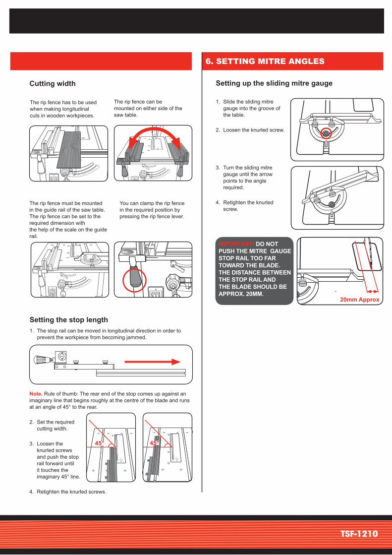
Stop height
1. The rip fence supplied with the table saw has two different guide faces.
2. For thick material you should use the stop rail as shown in Fig. A, for thin material you must use the stop rail as shown in Fig B.
3. To change over the stop rail to the lower guide face you have to loosen the two knurled screws in order to disconnect the stop rail from the holder.
4. Remove the two knurled screws through the one slot in the stop rail and insert in the other slot .
5. Remount the stop rail on the holder.
6. The procedure for changing over to the high guide face is similar.
FIG. A GUIDE FACE FOR THICK mATERIAL
FIG. B GUIDE FACE FOR THICK mATERIAL
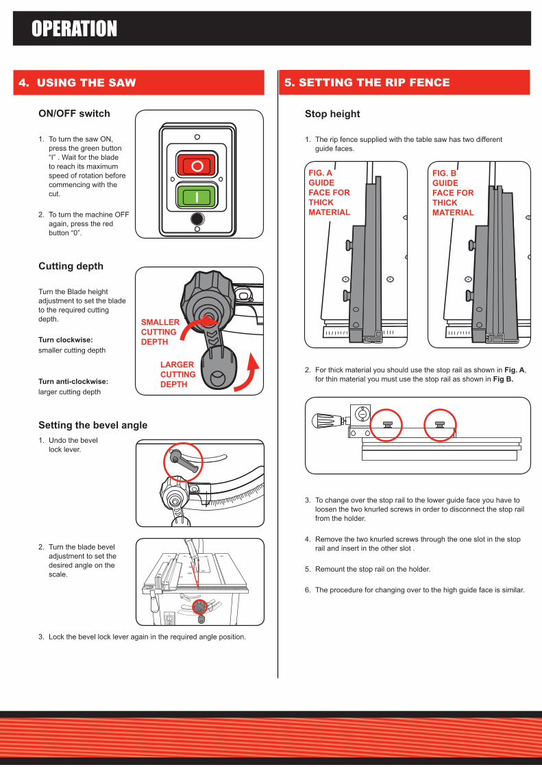
ON/OFF switch
1. To turn the saw ON, press the green button “I” . Wait for the blade to reach its maximum speed of rotation before commencing with the cut.
2. To turn the machine OFF again, press the red button “0”.
cutting depth
Turn the Blade height adjustment to set the blade to the required cutting depth.
Turn clockwise: smaller cutting depth
Turn anti-clockwise: larger cutting depth
Setting the bevel angle1. Undo the bevel
lock lever.
2. Turn the blade bevel adjustment to set the desired angle on the scale.
3. Lock the bevel lock lever again in the required angle position.
SMALLEr cUTTINg dEpTh
LArgEr cUTTINg dEpTh
6. SETTING MITRE ANGLES
Setting up the sliding mitre gauge
1. Slide the sliding mitre gauge into the groove of the table.
2. Loosen the knurled screw.
3. Turn the sliding mitre gauge until the arrow points to the angle required.
4. Retighten the knurled screw.
IMpOrTANT! dO NOT pUSh ThE MITrE gAUgE STOp rAIL TOO FAr TOWArd ThE BLAdE. ThE dISTANcE BETWEEN ThE STOp rAIL ANd ThE BLAdE ShOULd BE ApprOx. 20MM.
20mm Approx
45°45°
cutting width
Setting the stop length1. The stop rail can be moved in longitudinal direction in order to
prevent the workpiece from becoming jammed.
Note. Rule of thumb: The rear end of the stop comes up against an imaginary line that begins roughly at the centre of the blade and runs at an angle of 45° to the rear.
2. Set the required cutting width.
3. Loosen the knurled screws and push the stop rail forward until it touches the imaginary 45° line.
4. Retighten the knurled screws.
TSF-1210
The rip fence has to be used when making longitudinal cuts in wooden workpieces.
You can clamp the rip fence in the required position by pressing the rip fence lever.
The rip fence can be mounted on either side of the saw table.
The rip fence must be mounted in the guide rail of the saw table. The rip fence can be set to the required dimension with the help of the scale on the guide rail.
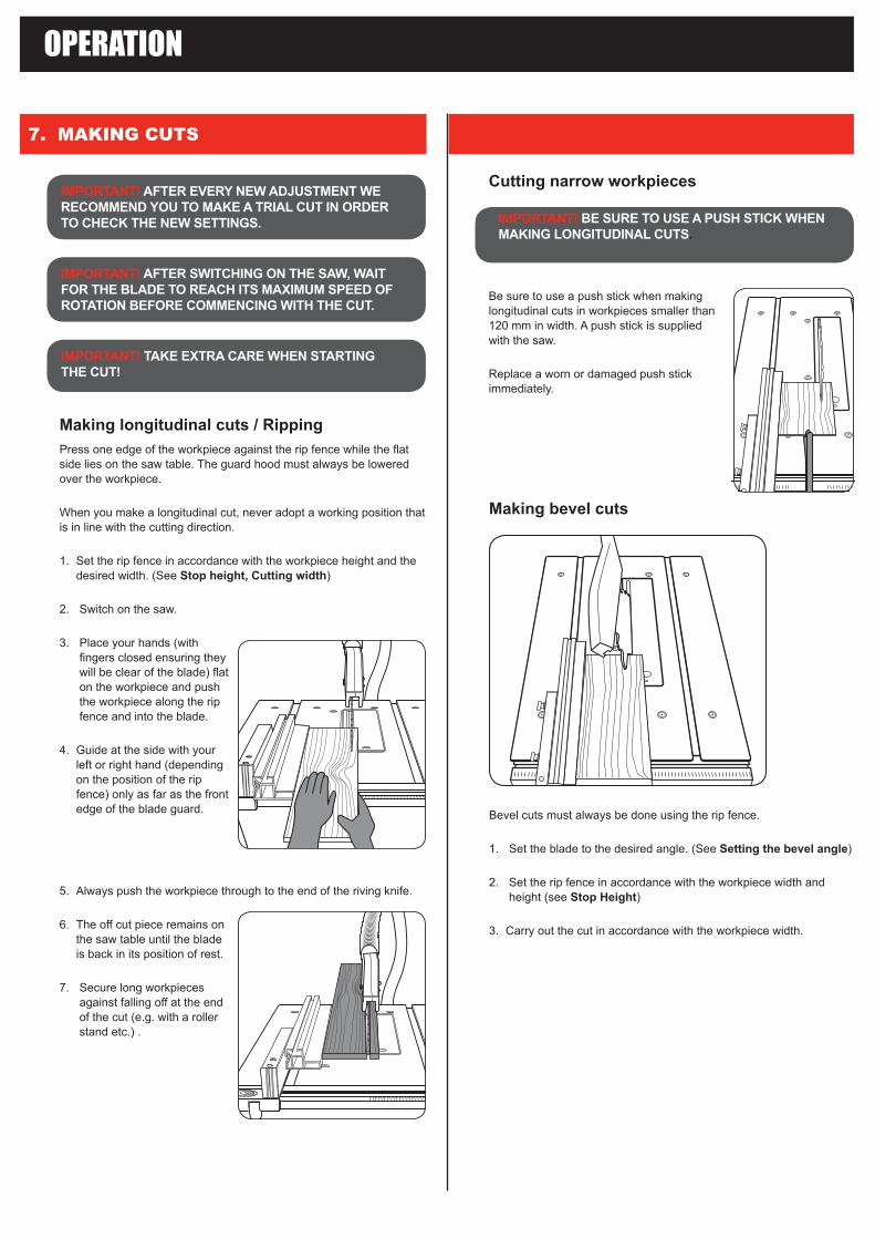
cutting narrow workpieces
Be sure to use a push stick when making longitudinal cuts in workpieces smaller than 120 mm in width. A push stick is supplied with the saw.
Replace a worn or damaged push stick immediately.
7. MAKING CUTS
OPERATION
IMpOrTANT! AFTEr EvEry NEW AdjUSTMENT WE rEcOMMENd yOU TO MAkE A TrIAL cUT IN OrdEr TO chEck ThE NEW SETTINgS.
IMpOrTANT! AFTEr SWITchINg ON ThE SAW, WAIT FOr ThE BLAdE TO rEAch ITS MAxIMUM SpEEd OF rOTATION BEFOrE cOMMENcINg WITh ThE cUT.
IMpOrTANT! TAkE ExTrA cArE WhEN STArTINg ThE cUT!
Making longitudinal cuts / rippingPress one edge of the workpiece against the rip fence while the flat side lies on the saw table. The guard hood must always be lowered over the workpiece.
When you make a longitudinal cut, never adopt a working position that is in line with the cutting direction.
1. Set the rip fence in accordance with the workpiece height and the desired width. (See Stop height, cutting width)
2. Switch on the saw.
3. Place your hands (with fingers closed ensuring they will be clear of the blade) flat on the workpiece and push the workpiece along the rip fence and into the blade.
4. Guide at the side with your left or right hand (depending on the position of the rip fence) only as far as the front edge of the blade guard.
5. Always push the workpiece through to the end of the riving knife.
6. The off cut piece remains on the saw table until the blade is back in its position of rest.
7. Secure long workpieces against falling off at the end of the cut (e.g. with a roller stand etc.) .
IMpOrTANT! BE SUrE TO USE A pUSh STIck WhEN MAkINg LONgITUdINAL cUTS.
Making bevel cuts
Bevel cuts must always be done using the rip fence.
1. Set the blade to the desired angle. (See Setting the bevel angle)
2. Set the rip fence in accordance with the workpiece width and height (see Stop height)
3. Carry out the cut in accordance with the workpiece width.

DESCRIPTION OF SYMBOLS
CARING FOR THE ENVIRONMENTPower tools that are no longer usable should not be disposed of with household waste but in an environmentally friendly way. Please recycle where facilities exist. Check with your local council authority for recycling advice.
Recycling packaging reduces the need for landfill and raw materials. Reuse of recycled material decreases pollution in the environment. Please recycle packaging where facilities exist. Check with your local council authority for recycling advice.
Inner Blade Flange SPTSF1210-82Blade Nut SPTSF1210-89Outer Blade Flange SPTSF1210-88V-Belt SPTSF1210-70Blade Ø250mm x Ø30mm x 24T SPTSF1210-87
BLAdES: You will find a selection of blades available from the Tool Shop at Bunnings Warehouse.
Spare parts can be ordered from the Special Orders desk at your local Bunnings Warehouse. For further information, or any parts not listed here, visit www.ozito.com.au or contact Ozito customer Service: Australia 1800 069 486 New Zealand 0508 069 486 E-mail: [email protected]
Operating mode S6 40%: continuous operation with idling (cycle time 10 minutes). To ensure that the motor does not become excessively hot it may only be operated for 40% of the cycle at the specified rating and must then be allowed to idle for 60% of the cycle.
SPARE PARTS
ADDITIONAL INFORMATION
Making cross cuts
1. Slide the sliding mitre gauge into one of the grooves in the table and adjust to the required angle (see Sliding mitre gauge).
2. Press the workpiece firmly against the sliding mitre gauge.
3. Switch on the saw.
4. Push the sliding mitre gauge and the workpiece toward the blade in order to make the cut.
5. Push the sliding mitre gauge forward until the workpiece is cut all the way through.
6. Switch off the saw again. Do not remove the off-cut until the blade has stopped rotating.
IMpOrTANT! ALWAyS hOLd ThE gUIdEd pArT OF ThE WOrkpIEcE. NEvEr hOLd ThE pArT WhIch IS TO BE cUT OFF
v Volts hz Hertz
~ Alternating current W Watts
/min Revolutions or reciprocation per minute Double insulated
Regulator compliance mark no No load speed
Read instruction manual
Wear hearing protectionWear eye protectionWear breathing protection
IMpOrTANT! dO NOT pUSh ThE MITrE gAUgE STOp rAIL TOO FAr TOWArd ThE BLAdE. ThE dISTANcE BETWEEN ThE STOp rAIL ANd ThE BLAdE ShOULd BE ApprOx. 20MM.
Overload protectionThis machine is fitted with overload protection. Should the motor be under excessive load during operation, the overload protection switch will be activated.
1. When this occurs, press the red button “0” and then turn off the power supply. Allow the machine to cool down for several minutes.
2. Switch the power back on at the power supply and push the overload switch.
3. To turn the machine on, push the green button "I" of the on/off switch.
4. Continue cutting and be aware of the load you are placing on the motor.
TROUBLESHOOTING

SPARE PARTS Tool: Table Saw 250mm (10”) 1500W Model No. TSF-1210
Item No. description part No.
how To Order
267082878995
105119135
Switch Assy. #25-28V-BeltInner & Outer Flange Kit #82,88Blade 250mmx30mmx24TBlade NutDust Extractor HoseGuard Assy. #105-108Rip Fence Assy. 109-115Mitre Gauge Assy.
SPTSF1210-26ASPTSF1210-70SPTSF1210-82KSPTSF1210-87SPTSF1210-89SPTSF1210-95SPTSF1210-105ASPTSF1210-119ASPTSF1210-135A
Available spare parts can be ordered through the Special Orders Desk at any Bunnings Warehouse. If you have any further questions, please contact Ozito Customer Service on:Australia: 1800 069 486New Zealand: 0508 069 [email protected]
The following is a list of spare parts carried by Ozito. Please contact Customer Service for any parts not listed.
Item No. description part No.
23
1011
1213
1415 16 17 18 19 20
21 22
51
141
9091 93
98
9495
9799
100
143
146
145
132104
131130
103102
78
143
144
144
933105106
107108
136 135134
137
120127125
138
142140139
123121122124129
128
2
2
33
33
4 4
4
141
67
8
24 25 26 27 28 29 30 3116
113112111
3496
14853 52
515049483738
39
40 41 434244454647
5455
14767 66
68 7071 72
7374
65
6463
75767779
6261
6059
5857
149
8081 82
838485
86
87
88
89
69
101
110
109 129
128 56
133
126
114115116117 118
119

This appliance is not intended for use by young or infirm persons unless supervised by a responsible person to ensure that they can use the appliance safely. young children should be supervised to ensure that they do not play with the appliance.
WArNINg! Before connecting a tool to a power source (mains switch power point receptacle, outlet, etc.) be sure that the voltage supply is the same as that specified on the nameplate of the tool. A power source with a voltage greater than that specified for the
tool can result in serious injury to the user,as well as damage to the tool. If in doubt, do not plug in the tool.Using a power source with a voltage less than the nameplate rating is harmful to the motor.a) This tool is designed to cut timber, timber products and some plastics.
Do not use the tool to cut any other materials.b) Do not cut firewood with this tool. The irregular shape of firewood makes it unsafe to cut
with this tool.c) prior to operating, connect a dust extractor to the tool. This will ensure a dust- free
environment for safer operation.d) Always use recommended size blade. Do not use smaller or larger blades.e) do not use dull or damaged blades. Unsharpened or improperly set blades produce narrow
*kerf causing excessive friction, blade binding and kickback.f) Never use damaged or incorrect blade washers or blade bolts. The blade bolt and
washers are specifically designed for the tool for optimum performance and safety of operation.g) Ensure the blade is properly fitted and rotates in the correct direction.
Incorrectly fitted blades can cause damage to the material and tool and injury to the operator.h) do not use damaged blades. This can result in serious injury to the operator and damage to
the tool.i) do not use abrasive or dado blades. This can result in serious injury to the operator and
damage to the tool.j) When the blade binds in material being cut, switch off the tool and wait for blade to
come to a complete stop. Investigate and take corrective action to eliminate cause of binding.k) Blade depth and bevel adjusting locking levers must be tight and secure before making
a cut. If blade adjustment shifts while cutting, it may cause binding and kickback.
l) do not use the tool without guards in place and operating correctly. Failure to adhere to this may cause damage to the material and tool and injury to the operator.
m) Ensure all clamps, levers and locking knobs are securely tightened prior to operation. This will result in projects being produced accurately and safely.
n) Support large panels to minimise risk of blade pinching and kickback. Large panels tend to sag under their own weight. The use of roller stands and/or extension tables is recommended.
o) Allow motor to reach full speed prior to inserting blade into timber. This will result in safe operation and clean cuts.
p) Never place any part of your body in the blade area while the power is connected. Injury will be prevented by the accidental starting of the tool.
q) Never attempt to stop the blade by wedging an object against the blade. This can result in serious injury to the operator and damage to the tool.
r) Extremely small pieces of timber should not be cut with this tool in either mode. This can result in serious injury to the operator caused by flying debris.
s) recommendation for the use of a residual current device with a rated residual current device of 30mA or less.
t) When ripping, always use the rip fence. This improves the accuracy of cut and reduces the chance of the blade binding.
u) Always use the push stick, especially when cutting narrow pieces of timber. Do not place hands in the near vicinity of the blade while operating the tool.
v) Ensure that the riving knife is properly positioned prior to operating. This will prevent the timber from binding up and stalling the blade.
w) do not over reach to retrieve material from behind the blade. This can result in serious injury to the operator.
x) Take care when using the table saw to cut a slot in timber. Ensure that blade guard is properly in place while operating the machine.
*kerf - groove cut in timber
TABLE SAW SAFETY WARNINGS
WArNINg! When using mains-powered tools, basic safety precautions, including the following, should always be followed to reduce risk of fire, electric shock, personal injury and material damage.
Read the whole manual carefully and make sure you know how to switch the tool off in an emergency, before operating the tool. Save these instructions and other documents supplied with this tool for future reference.The electric motor has been designed for 230V and 240V only. Always check that the power supply corresponds to the voltage on the rating plate.Note: The supply of 230V and 240V on Ozito tools are interchangeable for Australia and New Zealand.
If the supply cord is damaged, it must be replaced by an electrician or a power tool repairer in order to avoid a hazard.
Using an Extension LeadAlways use an approved extension lead suitable for the power input of this tool. Before use, inspect the extension lead for signs of damage, wear and ageing. Replace the extension lead if damaged or defective.When using an extension lead on a reel, always unwind the lead completely. Use of an extension lead not suitable for the power input of the tool or which is damaged or defective may result in a risk of fire and electric shock.
WArNINg! read all safety warnings and all instructions. Failure to follow the warnings and instructions may result in electric shock, fire and/or serious injury. Save all warnings and instructions for future reference. The term “power tool” in the
warnings refers to your mains-operated (corded) power tool or battery-operated (cordless) power tool.1. Work area safety a. keep work area clean and well lit. Cluttered or dark areas invite accidents. b. Do not operate power tools in explosive atmospheres, such as in the presence of flammable
liquids, gases or dust. Power tools create sparks which may ignite the dust or fumes. c. keep children and bystanders away while operating a power tool. Distractions can cause
you to lose control.2. Electrical safety a. power tool plugs must match the outlet. Never modify the plug in any way.
do not use any adapter plugs with earthed (grounded) power tools. Unmodified plugs and matching outlets will reduce risk of electric shock.
b. Avoid body contact with earthed or grounded surfaces, such as pipes, radiators, ranges and refrigerators. There is an increased risk of electric shock if your body is earthed or grounded.
c. do not expose power tools to rain or wet conditions. Water entering a power tool will increase the risk of electric shock.
d. do not abuse the cord. Never use the cord for carrying, pulling or unplugging the power tool. keep cord away from heat, oil, sharp edges or moving parts. Damaged or entangled cords increase the risk of electric shock.
e. When operating a power tool outdoors, use an extension cord suitable for outdoor use. Use of a cord suitable for outdoor use reduces the risk of electric shock.
f. If operating a power tool in a damp location is unavoidable, use a residual current device (rcd) protected supply. Use of an RCD reduces the risk of electric shock.
3. personal safety a. Stay alert, watch what you are doing and use common sense when operating a power
tool. Do not use a power tool while you are tired or under the influence of drugs, alcohol or medication. A moment of inattention while operating power tools may result in serious personal injury.
b. Use personal protective equipment. Always wear eye protection. Protective equipment such as dust mask, non-skid safety shoes, hard hat, or hearing protection used for appropriate conditions will reduce personal injuries.
c. prevent unintentional starting. Ensure the switch is in the off-position before connecting to power source and/or battery pack, picking up or carrying the tool. Carrying power
tools with your finger on the switch or energising power tools that have the switch on invites accidents.
d. remove any adjusting key or wrench before turning the power tool on. A wrench or a key left attached to a rotating part of the power tool may result in personal injury.
e. do not overreach. keep proper footing and balance at all times. This enables better control of the power tool in unexpected situations.
f. dress properly. do not wear loose clothing or jewellery. keep your hair, clothing and gloves away from moving parts. Loose clothes, jewellery or long hair can be caught in moving parts.
g. If devices are provided for the connection of dust extraction and collection facilities, ensure these are connected and properly used. Use of dust collection can reduce dust-related hazards.
4. power tool use and care a. do not force the power tool. Use the correct power tool for your application. The correct
power tool will do the job better and safer at the rate for which it was designed. b. do not use the power tool if the switch does not turn it on and off. Any power tool that
cannot be controlled with the switch is dangerous and must be repaired. c. disconnect the plug from the power source and/or the battery pack from the power tool
before making any adjustments, changing accessories, or storing power tools. Such preventive safety measures reduce the risk of starting the power tool accidentally.
d. Store idle power tools out of the reach of children and do not allow persons unfamiliar with the power tool or these instructions to operate the power tool. Power tools are dangerous in the hands of untrained users.
e. Maintain power tools. check for misalignment or binding of moving parts, breakage of parts and any other condition that may affect the power tool’s operation. If damaged, have the power tool repaired before use. Many accidents are caused by poorly maintained power tools.
f. keep cutting tools sharp and clean. Properly maintained cutting tools with sharp cutting edges are less likely to bind and are easier to control.
g. Use the power tool, accessories and tool bits etc. in accordance with these instructions, taking into account the working conditions and the work to be performed. Use of the power tool for operations different from those intended could result in a hazardous situation.
5. Service a. Have your power tool serviced by a qualified repair person using only identical
replacement parts. This will ensure that the safety of the power tool is maintained. b. If the supply cord is damaged, it must be replaced by the manufacturer,
its service agent or similarly qualified persons in order to avoid a hazard.
GENERAL POWER TOOL SAFETY WARNINGS
ELECTRICAL SAFETY
IMpOrTANT! rISk OF INjUry! NEvEr rEAch INTO ThE rUNNINg SAW BLAdE.

IN ORDER TO MAKE A CLAIM UNDER THIS WARRANTY YOU MUST RETURN THE PRODUCT TO YOUR NEAREST BUNNINGS WAREHOUSE WITH YOUR BUNNINGS REGISTER RECEIPT. PRIOR TO RETURNING YOUR PRODUCT FOR WARRANTY PLEASE TELEPHONE OUR CUSTOMER SERVICE HELPLINE:
Australia 1800 069 486New Zealand 0508 069 486
3 yEAr rEpLAcEMENT WArrANTyYour product is guaranteed for a period of 36 months from the original date of purchase. If a product is defective it will be replaced in accordance with the terms of this warranty. Warranty excludes consumable parts, for example: blade,push stick, spanners, bearings & carbon brushes.
WArNINgThe following actions will result in the warranty being void.
• If the tool has been operated on a supply voltage other than that specified on the tool.
• If the tool shows signs of damage or defects caused by or resulting from abuse, accidents or alterations.
• Failure to perform maintenance as set out within the instruction manual.
• If the tool is disassembled or tampered with in any way.• Professional, industrial or high frequency use.
WARRANTY
TO ENSURE A SPEEDY RESPONSE PLEASE HAVE THE MODEL NUMBER AND DATE OF PURCHASE AVAILABLE. A CUSTOMER SERVICE REPRESENTATIVE WILL TAKE YOUR CALL AND ANSWER ANY QUESTIONS YOU MAY HAVE RELATING TO THE WARRANTY POLICY OR PROCEDURE.
OZITO Australia/New Zealand (Head Office) 1-23 Letcon Drive, Bangholme, Victoria, Australia 3175.
The benefits provided under this warranty are in addition to other rights and remedies which are available to you at law.
Our goods come with guarantees that cannot be excluded at law. You are entitled to a replacement or refund for a major failure and for compensation for any other reasonably foreseeable loss or damage. You are also entitled to have the goods repaired or replaced if the goods fail to be of acceptable quality and the failure does not amount to a major failure.
Generally you will be responsible for all costs associated with a claim under this warranty, however, where you have suffered any additional direct loss as a result of a defective product you may be able to claim such expenses by contacting our customer service helpline above.
0712