specifications for electronic revenue ct and ct-vt …
TRANSCRIPT

Saudi Electricity Company الشركة السعودية للكهرباء
SEC DISTRIBUTION MATERIALS
SPECIFICATION
40-SDMS-02A REV.09
DATE: August 2018
40-SDMS-02A
REV.09
[August 2018]
SPECIFICATIONS
FOR
ELECTRONIC REVENUE CT AND CT-VT METER
This specification is property of SEC and currently optimized.
The optimization is not finalized and this specification
is subject to change or optimized without any notice.
Saudi Electricity Company الشركة السعودية للكهرباء
SEC DISTRIBUTION MATERIALS SPECIFICATION 40-SDMS-02A REV.09
DATE: August 2018
2
CONTENTS
1. SCOPE ............................................................................................................ 1
2. CROSS REFERENCES .................................................................................. 1
3. APPLICABLE CODES AND STANDARDS ................................................ 1
4. SERVICE CONDITIONS ............................................................................... 5
5. SYSTEM PARAMETERS .............................................................................. 5
6. DESIGN AND CONSTRUCTION ................................................................ 5
7. ELECTRICAL REQUIREMENTS ................................................................ 9
8. INPUT AND OUTPUT REQUIREMENT ................................................... 13
9. FUNCTIONAL REQUIREMENTS ............................................................. 27
10. DEFAULT SETTINGS ................................................................................. 55
11. MARKING OF METERS ............................................................................. 56
12. PACKING ..................................................................................................... 57
13. GUARANTEE .............................................................................................. 57
14. SUBMITTALS .............................................................................................. 59
15. TESTING ...................................................................................................... 62
16. TESTING METHOD .................................................................................... 68
17. OTHER REQUIREMENTS ......................................................................... 75
Saudi Electricity Company الشركة السعودية للكهرباء
SEC DISTRIBUTION MATERIALS
SPECIFICATION
40-SDMS-02A REV.09
DATE: August 2018
Page 1 / 86
1. SCOPE
This SEC Distribution Materials Specification (SDMS) describes the minimum
technical requirements for design, materials, manufacturing, test, performance and
supply of programmable electronic revenue meters (static meters) intended to be used
for revenue metering in the distribution system of Saudi Electricity Company
(hereinafter referred to as COMPANY).
This specification also describes the technical requirements for the electronic revenue
meters to be used in Automatic Meter Reading/Management (AMR/AMM)/Advanced
Metering Infrastructure (AMI) and SMART GRID.
2. CROSS REFERENCES
2.1. This specification shall be read in conjunction with SEC General Specification
No. 01-SDMS-01 (latest revision) titled “General Requirements for all
Equipment / Materials” considered as an integral part of this specification.
2.2. This specification shall also be read in conjunction with COMPANY purchase
order requirements.
3. APPLICABLE CODES AND STANDARDS
The latest revision of the following codes and standards shall be applicable for the
equipment / material covered by this specification. In case of any deviation, the Vendor
may propose equipment / material conforming to equivalent alternative codes and
standards. However, the provisions of COMPANY’s standards shall supersede the
provisions of these standards in case of any conflict.
IEC 60068-2-1 Environmental testing – Part 2-1: Tests – Test A: Cold
IEC 60068-2-2 Environmental testing – Part 2-2: Tests – Test B: Dry heat
IEC 61000-4-2 Electromagnetic compatibility (EMC) - Part 4-2: Testing and
measurement techniques - Electrostatic discharge immunity test
IEC 61000-4-3 Electromagnetic compatibility (EMC) - Part 4-3: Testing and
measurement techniques - Radiated, radio-frequency,
electromagnetic field immunity test
IEC 61000-4-4 Electromagnetic compatibility (EMC) - Part 4-4: Testing and
measurement techniques - Electrical fast transient/burst immunity
test

Saudi Electricity Company الشركة السعودية للكهرباء
SEC DISTRIBUTION MATERIALS
SPECIFICATION
40-SDMS-02A REV.09
DATE: August 2018
Page 2 / 86
IEC 61000-4-5 Electromagnetic compatibility (EMC) - Part 4-5: Testing and
measurement techniques - Surge immunity test
IEC 61000-4-6 Electromagnetic compatibility (EMC) - Part 4-6: Testing and
measurement techniques - Immunity to conducted disturbances,
induced by radio-frequency fields
IEC 61000-4-8 Electromagnetic compatibility (EMC) - Part 4-8: Testing and
measurement techniques - Power frequency magnetic field
immunity test
IEC 61000-4-11 Electromagnetic compatibility (EMC) - Part 4-11: Testing and
measurement techniques - Voltage dips, short interruptions and
voltage variations immunity tests
IEC 62052-11 Electricity metering equipment (AC) – General requirements,
tests and test conditions – Metering equipment
IEC 62052-21 Electricity metering equipment (AC) - General requirements, tests
and test conditions - Tariff and load control equipment
IEC 62053-22 Electricity metering equipment (a.c.) - static meters for active
energy (classes 0.2 and 0.5)
IEC 62053-23 Electricity metering equipment (a.c.) - static meters for reactive
energy (classes 2 and 3)
IEC 62053-31 Electricity metering equipment (a.c.) – Particular Requirement –
Part 31: Pulse Output Devices for Electromechnical and
Electronic Meters (Two Wires Only)
IEC 62054-11 Electricity metering (a.c.) – Tariff and load control – Particular
requirements for electronic ripple control receivers
IEC 62054-21 Electricity metering (a.c.) – Tariff and load control – Particular
requirements for time switches
IEC 62056-1-0 Electricity metering data exchange – The DLMS/COSEM suite –
Part 1-0: Smart metering standardisation framework
IEC 62056-21 Electricity metering - Data exchange for meter reading, tariff and
load control – Direct local data exchange
IEC 62056-42 Electricity metering - Data exchange for meter reading, tariff and
load control – Physical layer
IEC 62056-46 Electricity metering - Data exchange for meter reading, tariff and
load control – Data link layer

Saudi Electricity Company الشركة السعودية للكهرباء
SEC DISTRIBUTION MATERIALS
SPECIFICATION
40-SDMS-02A REV.09
DATE: August 2018
Page 3 / 86
IEC 62056-47 Electricity metering - Data exchange for meter reading, tariff and
load control – COSEM transport layers for IP networks
IEC 62056-5-3 Electricity metering - Data exchange for meter reading, tariff and
load control – COSEM Application layer
IEC 62056-6-1 Electricity metering - Data exchange for meter reading, tariff and
load control – Object identification system (OBIS)
IEC 62056-6-2 Electricity metering - Data exchange for meter reading, tariff and
load control – Interface classes
IEC 62058-11 Electricity metering equipment (AC) - Acceptance inspection -
Part 11: General acceptance inspection methods
IEC 62058-21 Electricity metering equipment (AC) - Acceptance inspection -
Part 21: Particular requirements for electromechanical meters for
active energy (classes 0,5, 1 and 2)
IEC 62059-31-1 Electricity metering equipment – Dependability – Accelerated
Reliability Testing – Elevated temperature and humidity
IEC 62357 Power system control and associated communications –
Reference architecture for object models, services and protocols.
IEC 60834-1 Tele-protection equipment of power systems – Performance and
testing – Part 1: Command systems
IEC 60664 Insulation coordination within Low Voltage System including
clearances and creep-age distance for equipment
IEC 60695-2-11 Fire Hazard Testing - Part 2-11: Glowing/Hot-Wire Based Test
Methods
IEC 60817-1987 Spring operated impact tests apparatus test and its calibration
IEC 60947-7-1 Test requirements of Terminal Blocks
IEC 60947-4-1 Low-voltage switchgear and controlgear - Part 4-1: Contactors
and motor-starters - Electromechanical contactors and motor-
starters
IEC 60529 Degrees of Protection provided by Enclosure IP Classification
Designation
IEEE 802.3at Power over Ethernet+
IEEE C62.41 Recommended Practice on Surge Voltage in Low-Voltage AC
Power Circuits

Saudi Electricity Company الشركة السعودية للكهرباء
SEC DISTRIBUTION MATERIALS
SPECIFICATION
40-SDMS-02A REV.09
DATE: August 2018
Page 4 / 86
EN 50470-3 Electricity metering equipment Static meters for active energy,
classes A, B and C
ASTM D-4098 Thermosetting Resins
ASTM D-3935 Polycarbonate Resins
EIA/TIA-485-A Electrical Characteristics of Generators and Receivers for Use in
Balanced Digital Multipoint Systems
NIST FIPS 180-1 Secure Hash Standard
NIST SP 800-38D Recommendation for Block Cipher Modes of Operation :
Galois/Counter Mode (GCM) and GMAC
NISP SP 800-57 Recommended for Key Management
NIST SP 800-90A Recommendation for Random Number Generation Using
Deterministic Random Bit Generators
ISO/IEC 11770-3 Information technology - Security techniques - Key management
ISO/IEC 18033-2 Information technology - Security techniques - Encryption
algorithms - Part 2 : Asymmetric cipher
IEC 15426-1 BAR CODE
Green Book 8th Ed. DLMS/COSEM Architecture and Protocols
Blue Book 12th Ed. COSEM Interface Classes an OBIS Object Identification System
SG-AMI-1-2009 NEMA Smart Grid Standards Publication - Requirements for
Smart Meter Upgradeability
IEC 61000-4-7 Electromagnetic compatibility (EMC) – Part 4-7: Testing and
measurement techniques – General guide on harmonics and
interharmonics measurements and instrumentation, for power
supply systems and equipment.
OIML R46-1 The Test Procedure for Magnetic Interference Tampering
Protection shall be that of OIML R46-1/-2 Edition 2012 (E),
available at https://www.oiml.org/en/files/pdf_r/r046-p-e12.pdf,
section 6.3.13 "continuous (DC) magnetic induction of external
origin"
Saudi Electricity Company الشركة السعودية للكهرباء
SEC DISTRIBUTION MATERIALS
SPECIFICATION
40-SDMS-02A REV.09
DATE: August 2018
Page 5 / 86
4. SERVICE CONDITIONS
The meter will be installed indoor and / or outdoor as referred to the latest revision of
General Specification No. 01-SDMS-01. In outdoor installations, the meter shall be
enclosed in weatherproof fiberglass meter box. The air temperature inside the meter box
may be regarded as 75°C due to direct solar radiation, plus the effect of any internal
heating.
Temperature range:
4.1. Limit range for storage and transportation -10°C to 85°C
4.2. Limit range for operation -10°C to 75°C
4.3. Humidity limits from IEC 62052-11 Standard
5. SYSTEM PARAMETERS
The meter shall be suitable for operation in COMPANY’s distribution system conditions
as per the latest revision of General Specification No.01-SDMS-01. The meter shall be
deemed to meet the requirements without any adverse effect over the life cycle.
6. DESIGN AND CONSTRUCTION
6.1. General
6.1.1. The Meter shall be compact, rugged and reliable in design. The Vendor
shall furnish detailed dimensional drawings of the Meter and its
mounting arrangement along with the offer.
6.1.2. The Meter shall be designed and constructed in such a way as to avoid
introducing any danger to the Meter in use and under normal
conditions, so as to ensure specially personnel safety against electric
shock.
6.1.3. All parts of the Meter, which are subject to corrosion under normal
working conditions, shall be protected effectively. Any protective
coating shall not be liable to damage by ordinary handling or damage
due to exposure to air, under normal working conditions.
6.1.4. All pars of the Meter which are subject to corrosion under normal
working conditions will show no damage or evidence of corrosion
under the following test:
IEC 60068-2-52, Severity (2)
Initial measurements:

Saudi Electricity Company الشركة السعودية للكهرباء
SEC DISTRIBUTION MATERIALS
SPECIFICATION
40-SDMS-02A REV.09
DATE: August 2018
Page 6 / 86
o A visual examination shall be performed to verify that all
required mounting, case, cable, and signal fasteners are present.
In addition, the meter shall have its cover and terminal cover
installed as expected for normal operation.
Pre Conditioning
o No cleaning is permitted before the test is performed. The meters
shall be removed from their shipment packaging presumed
ready for testing.
o Any protective coverings used for shipping shall be removed
Recovery
o No washing or rinsing is permitted.
o Air blast is permitted as specified.
o Drying as specified.
Final Measurements
o A visual examination shall be performed and no exposed metal
parts shall show evidence of corrosion.
o A visual examination shall be performed and no metal parts of
the terminals shall show any evidence of corrosion.
o An insulation test according to IEC 62052-11 clause 7.3 and the
voltage limits are located in tables 3a & 3b of this standar.
o A functional test, including operation of the connect/disconnect
switch. Meter shall show no damage or change of information
and shall operate correctly.
6.1.5. Meter shall have an integrated PRIME PLC communication module
whose operation can be enable and disable (Default state: Enable) both
locally and remotely.
6.1.6. Meter shall also support external communication module of various
technologies when PRIME PLC communication module is disabled.
6.1.7. All internal and external wiring required to install the Meter shall be
governed in a way to completely avoid any conflict with the
connections of power cables and communication cables.
6.1.8. The components and modules shall be the same ones as those used and
tested during the Type Test. All the components and modules shall
keep high reliability required during the Meter life time.
6.1.9. The cables used shall be easily replaceable, and have the sheathed
wiring cables with nonflammable characteristics.

Saudi Electricity Company الشركة السعودية للكهرباء
SEC DISTRIBUTION MATERIALS
SPECIFICATION
40-SDMS-02A REV.09
DATE: August 2018
Page 7 / 86
6.1.10. Meter Printed Circuit board should not have any flexible wire
connected from PCB to PCB
6.2. Case
6.2.1. The case of the meter shall be made of nonmetallic material. It shall
be made of non-flammable phenol or high-grade polycarbonate resin.
6.2.2. The meter shall have an adequate dust proof and moisture proof case,
which can be sealed in such a way that the internal parts of the meter
are accessible only after breaking the seals. The degree of protection
shall be IP-54 or better. The meter’s electronics shall have a layer of
special coating applied to provide sealing against dust, water, and
vermin and to ensure high humidity resistance performance.
6.2.3. Top and bottom mountings shall be metallic with anti rust coating.
Thickness of these mountings shall not be less than 1.5 mm bolted /
riveted to the meter case. Plastic mountings may also be acceptable
provided the thickness of the mountings is enough to withstand the
mounting pressure. Bottom mounting should be inside the terminal
cover.
6.2.4. If plastic mountings are used per 6.2.3, they shall not show any adverse
effects (split, crack, gross deformation, break) with a suitably rated
fastener under 4.5 N-m (40 in.-lb.) of torque when attached to a
concrete surface.
6.2.5. Adequate sealing provision shall be provided in different parts of the
meter, i.e., terminal cover, meter cover and energy storage device
cover if used.
6.2.6. The overall and mounting dimensions and top & bottom mounting
arrangements shall be provided similar to the sketch as given in
drawing No. SEC/KWH-S-01.
6.2.7. All the screws used in the meter shall be of slotted head type, only
except the screws used for the internal assembly of meter parts.
6.2.8. The Meter case shall have the protective structure against outer EMI
(Electro Magnetic Interference).
6.2.9. The Meter case shall not show any adverse effects (change of color,
cracking, break) following the solar radiation test as specified in
Table 10 in Section 15.7.6

Saudi Electricity Company الشركة السعودية للكهرباء
SEC DISTRIBUTION MATERIALS
SPECIFICATION
40-SDMS-02A REV.09
DATE: August 2018
Page 8 / 86
6.3. Terminals and Terminal Block
6.3.1. The terminals shall be grouped in a terminal block of adequat
e insulating properties and mechanical strength. They shall be
arranged for bottom connection. The terminals shall be made
according to the requirements described in section 5.4 Terminals –
Terminal block (s) – Protective earth terminal of IEC62052-11. The
cover will not be transparent. It will use the same material as top cover.
6.3.2. The terminals (holes) shall have a tightly screwing structure of
terminal surfaces for the inserted cables not affecting the meter case in
addition to 5.4 of IEC 62052-11.
6.3.3. The terminals shall be suitable for copper conductors and provided
with minimum of two (2) screws for each conductor (The screw
bottom diameter shall be more than 3.5 mm to tightly fix the
conductors inside the terminals). The bore diameter for phase and
neutral terminals shall be as given in the Table No.1 below.
Table No.1 – Bore diameter
Bore diameter of each terminal (mm) Kind & Size of conductor
4.5 – 5 2.5 ㎟ soft drawn stranded copper
6.3.4. The terminal block shall include additional connection terminals for
the communication interfaces, output relay and the signals of kWH and
EOI.
6.4. Terminal Cover
Terminal cover shall be made of the same materials as that of the meter case
and sealed independently up the meter cover. The terminal cover shall include
information indicating the correct phase sequence and connections as per
drawing No. SEC/KWH-S- 02. The terminal block shall not be visible through
the terminal cover.
6.5. Meter Cover and Nameplate
6.5.1. The cover of the meter shall be made of opaque, shatterproof, ultra
violet stabilized nonmetallic material with a clear glass or
polycarbonate window.
6.5.2. The clear window shall be large enough to view the display and the
nameplate details and insured transparency during the whole service
Saudi Electricity Company الشركة السعودية للكهرباء
SEC DISTRIBUTION MATERIALS
SPECIFICATION
40-SDMS-02A REV.09
DATE: August 2018
Page 9 / 86
life of the meter.
6.5.3. The meter cover shall have enough room to provide the optical port,
display push-button and optical test outputs. These components shall
be arranged either within or outside the window area. The metallic ring
should be backside of the meter cover.
6.5.4. The meter shall work without any abnormal operation, when the meter
cover is pressed down against the meter base.
7. ELECTRICAL REQUIREMENTS
7.1. All electrical requirements shall be referred to General Specification No. 01-
SDMS-01.
7.2. The rated current (In) and the maximum current (Imax) of the meter shall
comply with following.
7.2.1. Rated current (In): 1.5 (A)
7.2.2. Maximum current (Imax): 6 (A)
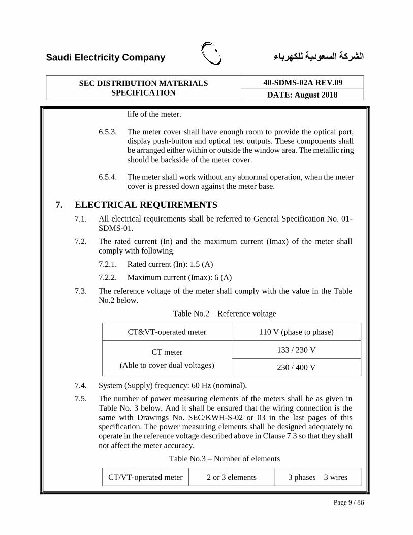
7.3. The reference voltage of the meter shall comply with the value in the Table
No.2 below.
Table No.2 – Reference voltage
CT&VT-operated meter 110 V (phase to phase)
CT meter
(Able to cover dual voltages)
133 / 230 V
230 / 400 V
7.4. System (Supply) frequency: 60 Hz (nominal).
7.5. The number of power measuring elements of the meters shall be as given in
Table No. 3 below. And it shall be ensured that the wiring connection is the
same with Drawings No. SEC/KWH-S-02 or 03 in the last pages of this
specification. The power measuring elements shall be designed adequately to
operate in the reference voltage described above in Clause 7.3 so that they shall
not affect the meter accuracy.
Table No.3 – Number of elements
CT/VT-operated meter 2 or 3 elements 3 phases – 3 wires

Saudi Electricity Company الشركة السعودية للكهرباء
SEC DISTRIBUTION MATERIALS
SPECIFICATION
40-SDMS-02A REV.09
DATE: August 2018
Page 10 / 86
CT-operated meter 3 elements 3 phases – 4 wires
7.6. The temperature rise (comparing to an ambient temperature) at any point of the
electrical circuit, insulation and the external surface of the meter shall not
exceed 30°C with an ambient temperature not exceeding 55°C.
7.7. The meter shall have a fully redundant power supply; i.e. withstanding any
phase-neutral inversion, missing phases or missing neutral.The meter shall be
designed and constructed in such a way as to avoid introducing any
electromagnetic interference (surge, impulse, noise, etc.) in normal use and
under normal conditions.
7.8. The Meter shall start to calculate consumption and demand quantities less than
3 seconds after power application.
7.9. The meter shall have a protective circuit to protect itself against any electric
trouble or electromagnetic interference from other devices connected to the
meter through interface such as communication port, signal cable and power
cable.
7.10. Accuracy requirements
The accuracy class of the meter shall comply with the value in the Table No.4
below.
Table No.4 – Accuracy class
Active energy
CL 0.5
Reactive energy CL 2.0
7.10.1. Limits of error due to variation of the current
For active energy the percentage errors of the meters shall comply with
the clause 8.1 of IEC 62053-22.
For reactive energy, the percentage errors of the meters shall comply
with the clause 8.1 of IEC 62053-23.
7.10.2. Limits of error due to influence quantities
The additional percentage error due to the change of influence
quantities with respect to reference conditions shall comply with the
clause 8.2 of IEC 62053- 22, 23.

Saudi Electricity Company الشركة السعودية للكهرباء
SEC DISTRIBUTION MATERIALS
SPECIFICATION
40-SDMS-02A REV.09
DATE: August 2018
Page 11 / 86
7.10.3. Initial start-up of the meter
The meter shall be normally functional within five (5) seconds after
the reference voltage is applied to the meter terminals
7.10.4. Test of no-load condition
When the voltage equal to 115 % of the reference voltage is applied
for the specified period with no current flowing in the current circuit,
the test output of the meter shall not produce more than one (1) pulse.
For the specified period for no-load test and the detailed test method,
clause 8.3.2 of IEC 62053-22 shall be referred.
7.10.5. Starting current
For active energy, the meter shall start and continue to register at the
starting current value in the Table No.5 below.
Table No.5 – Starting current
Power factor Starting current (CL = 0.5)
1 (cosΦ = 1) 0.001 In
For reactive energy, the meter shall start and continue to register at
0.003 In and zero (0) power factor (sinΦ=1).
7.10.6. Accuracy test shall be applied with all import / export energies (powers)
flowing in both direction and all measurement points.
7.10.7. Power consumption
The power consumption of the meter (except for the power supply to
external modem or gateway) shall not exceed the values in the Table
No.6.
Table No.6 - Power consumption including the power supply
Meters Voltage circuit including
power supply (per phase)
Current circuit
(per circuit)
CL = 0.5
3 phase(s) 2 W and 10 VA 1 VA
Saudi Electricity Company الشركة السعودية للكهرباء
SEC DISTRIBUTION MATERIALS
SPECIFICATION
40-SDMS-02A REV.09
DATE: August 2018
Page 12 / 86
7.10.8. The internal circuit of the meter shall be designed as to prevent the
meter from being influenced by any abnormal status of externally
connected devices (e.g. external modem) or communication line (e.g.
RS-485).
7.10.9. The meter shall be equipped with protection device against electrical
surge flowing into the meter through power supply line,
communication line and signal line. The internal power source for the
meter and the DC power supply for the external modem shall be
isolated.
7.10.10. Prevention of PLC Signal Attenuation and Distortion
7.10.10.1. The meter shall not cause PLC signal attenuation in all
used frequency band (i.e. 150kHz to 30 MHz) for PLC,
which may be caused by some components or boards
inside the meters, in case of the meter which is used with
external PLC modem.
7.10.10.2. PLC Signal Insertion Loss (Signal Attenuation) for RS-
485 Signal Port of the meter shall be less than 5dBm.
7.10.10.3. The meter shall comply with the CISPR 22 class B limits
as a regulation for conducted emissions (frequency range
similar to clause 7.10.10.1).
7.10.10.4. The meter’s noise level generated from the internal
alternating power source or internal modules shall be less
than -70dBm.

Saudi Electricity Company الشركة السعودية للكهرباء
SEC DISTRIBUTION MATERIALS
SPECIFICATION
40-SDMS-02A REV.09
DATE: August 2018
Page 13 / 86
8. INPUT AND OUTPUT REQUIREMENT
8.1. Display
8.1.1. The display shall be of a high-contrast and easy-to-read Liquid Crystal
Display (LCD), which offers a wide array of information and
flexibility.
8.1.1.1. Viewing angle: LCD display digits and operation status
shall be clearly understandable at least 2m distance from
the meter front.
8.1.1.2. Display method: Segment Type or Dot Matrix
8.1.1.3. Connection: Pin or Elastomeric connector
8.1.1.4. LCD window shall be polycarbonate or better materials
8.1.1.5. LCD shall be visible from different sides and different
angles as per the Meter box and installation guide
document (Schedule B - Attachment I - Installation Guide
of Meter Box)
8.1.2. The LCD shall withstand environmental conditions specified in 01-
SDMS-01 latest revision and shall not have any change in color,
contrast or brightness during the entire meter life period. The
temperature limit range of operation for the LCD is the same as that of
the meter mentioned in clause 4 of this specification.
8.1.3. Legends / dimensions recomendations shall be as shown in the
drawing No. SEC/KWH-S-03 or any other similar LCD which
provides equivalent text / legend information.
8.1.4. The display shall have access to all the metering parameters as given
in the functional requirements and shall be tailored to display only the
required information by masking-out undesired information.
8.1.5. The meter shall display the primary values of the (total and TOU)
energy, average demand, maximum demand, cumulative maximum
demand, load profile (clause 9.1.2, 9.1.3, 9.1.4, 9.1.5, 9.1.6, 9.1.7
respectively), if CT ratio and VT ratio are configured into the meter.
The primary values in this context mean the actual values which are
multiplied by CT ratio and VT ratio, and the secondary values are the
values which are not multiplied by CT ratio and VT ratio.
8.1.6. In case of instantaneous measurement values, the default display
configuration of the instantaneous measurement values is the

Saudi Electricity Company الشركة السعودية للكهرباء
SEC DISTRIBUTION MATERIALS
SPECIFICATION
40-SDMS-02A REV.09
DATE: August 2018
Page 14 / 86
secondary values (refer to clause 9.6).
8.1.7. For all register values the number of digits shall be the maximum eight
(8) digits. The number of digits and decimal places for display shall be
configurable.
8.1.8. The default display units and the number of decimals to be displayed
shall be as follows. Note that the default numbers and units to display
shown below do not define the actual resolution of measurement
values. (Refer to the related clauses in the supplementary OBIS
specification to see the actually registered resolutions).

Saudi Electricity Company الشركة السعودية للكهرباء
SEC DISTRIBUTION MATERIALS
SPECIFICATION
40-SDMS-02A REV.09
DATE: August 2018
Page 15 / 86
Table No.7 – Default Units to Display
Values Integer Decimal Unit
Energy and
Demand
(Clause 8.1.5)
Energy 8 0 kWh, kVarh, kVAh
Demand 8 0 W, Var, VA
Instantaneous
Measurement
Values
(Clause 9.6)
Voltage 6 2 Volt
Current 5 3 Amp
Power 8 0 W, Var, VA
Power
Factor 1 3 N/A
Frequency 2 2 Hz
8.1.9. In case the metered energy values exceed eight (8) digits, the displayed
value shall be rolled over to zero (0). After the rollover, the lowest
eight (8) digits shall be displayed. A flag must be available for this
event,the meter shall have required OBIS codes for this flag.
8.1.10. For CT and CT-VT operated meters, the CT ratio and VT ratio shall
be configurable (only CT ratio for CT meter).
8.1.11. For Item No.9 of drawing No. SEC/KWH-S-04, the meter shall display
the OBIS code including at least three (3) digits of C, D and E codes
on the LCD panel, and a table containing a short description of the
codes shall be fixed on the front panel.

Saudi Electricity Company الشركة السعودية للكهرباء
SEC DISTRIBUTION MATERIALS
SPECIFICATION
40-SDMS-02A REV.09
DATE: August 2018
Page 16 / 86
Table No.8 – Display OBIS Code on the Front Panel
[Remark 8.1.11] If the LCD displays 1.8.0 (or 180), the value means ΣLi
Active power+ (1), Time integral 1 (8) and total (0).
8.1.12. The display shall also provide the following indicators whenever it is
required:
8.1.12.1. A register value with its appropriate unit, and DLMS/
COSEM/ OBIS code of the parameter of which the register
is storing
8.1.12.2. A tariff number indicates which tariff period is in view.
8.1.12.3. A 3-Phase and Neutral status indicator remains static
throughout the operation and blinks if the corresponding
phases trip.
8.1.12.4. The vendor will supply an anomaly indicator, which blinks
when there is failure in the electronic components,
overflow in calculation or any other error which results in
meter malfunction.
8.1.12.5. A reverse direction indicator blinks when the active energy
in one or more of the phases is flowing in the reverse
(export) direction. (Alternately a four quadrant indicator is
also acceptable provided it shall blink when the measured
Group C Group D Group E
1 ΣLi Active power+ 0 Billing period
average 0 Total
2 ΣLi Active power- 4 Current average 1 1 Rate 1
3 ΣLi Reactive power+ 6 Maximum 1 2 Rate 2
4 ΣLi Reactive power- 7 Instantaneous value 3 Rate 3
5 ΣLi Reactive power QI 8 Time integral 1 4 Rate 4
6 ΣLi Reactive power QII 5 Rate 5
7 ΣLi Reactive power QIII 6 Rate 6
8 ΣLi Reactive power QIV 7 Rate 7
9 ΣLi Apparent power+ 8 Rate 8
10 ΣLi Apparent power-
13 ΣLi Power factor
14 Supply frequency

Saudi Electricity Company الشركة السعودية للكهرباء
SEC DISTRIBUTION MATERIALS
SPECIFICATION
40-SDMS-02A REV.09
DATE: August 2018
Page 17 / 86
active energy in one or more of the phases is in the export
direction).
8.1.12.6. A energy storage device level indicator blinks when the
main energy storage device is required replacement or
percentage of the energy storage device remaining will be
indicated on the screen. (open for the vendor)
8.1.12.7. A communication indicator is lighted when the meter is
communicating through one of its communication ports.
[Remark 8.1.12] The indicator presentation different from ‘DISPLAY
ARRANGEMENT’ in DRAWING No. SEC/KWH-04 may be accepted at
COMPANY’s discretion. However, the above functional display requirements
shall be fulfilled even in such a case.
8.1.13. The meter periodically check meter status (self-diagnostic
information) and display its status on LCD screen. When there is the
meter reading data request, the meter shall have the transfer function
of self-diagnostic information with meter reading data.
8.1.14. The meter structure shall be securely made to prevent the internal data
change, such as measurement data and historical recording through the
meter body or communications by unauthorized manipulation.
8.1.15. The detection function of “Phase and neutral wire swapped (L1, L2,
L3)” shall be configurable [default: CD, (CD: no condenser
installation, CE: condenser installation)], as per the customer’s leading
phase static condenser installation status.
8.1.15.1. If CE is set, the meter shall detect the abnormal status of
“Phase and neutral wire swapped (L1, L2, L3)”, only if the
consumed current goes over 10% of rated current.
8.1.15.2. The leading phase static condenser will be installed by a
customer who has considerable motor load (lagging factor)
to improve the power factor by reducing Reactive power.
8.1.15.3. In this case, the meter may detect wrong cable connections,
even there are no wrong cable connections depending on
the operation state of the leading phase static condenser of
the customer side.
8.1.15.4. Therefore, if the leading phase static condenser is installed
at the customer side, set the setting mode with CE and
detect a wrong connection only with more than 10% of the

Saudi Electricity Company الشركة السعودية للكهرباء
SEC DISTRIBUTION MATERIALS
SPECIFICATION
40-SDMS-02A REV.09
DATE: August 2018
Page 18 / 86
rated current of the meter.
8.1.16. Average / maximum voltages and currents per each phase
8.1.16.1. If the calculation period of average current and average
voltage shall be configurable [default: 5 seconds, (1, 5, 10,
15, 30, 60 seconds or minutes)].
8.1.16.2. If a new average value of current or voltage go beyond the
previous average value, the new average value shall be
copied on to the maximum load current or the maximum
voltage respectively (minimum measurement range: for
current - ±0 ~ 120% of maximum current, for voltage - 0
~ 120% of Phase-to-Phase reference voltage).
8.1.16.3. Whenever a new maximum value of current or voltage is
generated, the generation date / time of the maximum
value shall be updated.
8.1.16.4. If a new maximum current load goes beyond the meter’s
maximum current, the meter shall set maximum current
load operation event.
8.1.16.5. If the current load goes under the meter’s maximum
current, the meter shall reset the maximum current load
operation event status.
8.1.16.6. These average and maximum values of current and voltage
shall be reset to zero (0), whenever there is EOB reset or
Manual Reset.
8.1.17. Temperature of the internal part of the meter
8.1.17.1. The meter shall have an internal temperature sensor and
the temperature sensing function shall be configurable
(default: enable).
8.1.17.2. The temperature measurement range shall be at least -40 ~
100℃. The temperature recording shall be possible by 1℃
difference (accuracy range: ±2℃).
8.1.17.3. The meter shall present current temperature, temperature
event and have the function to configure temperature over
limit threshold (default: 75℃).
8.1.17.4. Whenever the meter’s internal temperature goes beyond
Saudi Electricity Company الشركة السعودية للكهرباء
SEC DISTRIBUTION MATERIALS
SPECIFICATION
40-SDMS-02A REV.09
DATE: August 2018
Page 19 / 86
the temperature over limit threshold value or existing
temperature over for more than five (5) seconds, the meter
shall update the temperature over value, event and the date
/ time of the event.
8.1.17.5. If the temperature goes below the threshold value, the
meter shall reset the event status.
8.1.17.6. The temperature over value shall be reset to zero (0),
whenever there is EOB reset or Manual Reset.
8.1.18. Voltage under limit threshold (Sag) and over limit threshold (Swell)
8.1.18.1. If the calculation period of Sag and Swell shall be
configurable [default: 5 seconds, (1, 5, 10, 15, 30, 60
seconds or minutes)].
8.1.18.2. If Sag or Swell event happens, the event and date / time
shall be recorded. Minimum Sag event measurement range
is 30 ~ 90% and Minimum Swell event measurement range
is 110 ~ 120% of the referenced voltage value.
8.1.18.3. If continuous generations of Sag or Swell occur
immediately upon the first Sag or Swell event with within
± 2% voltage setting values, the Sag or Swell value shall
not be recorded as additional events.
8.1.19. Meter firmware upgrade and time synchronization (local and remote).
8.1.19.1. The meter shall provide firmware upgrade function
remotely and locally by DLMS clients. The vendor shall
provide technical support for its meters firmware upgrade
via AMR/AMM server. Meters shall comply with SG –
AMI -1 -2009 for Firmware upgradation.
8.1.19.2. The meter shall provide time synchronization function to
remotely and locally by DLMS clients.
8.1.20. Self-diagnostics and Alarms on LCD screen
8.1.20.1. Clock Initialization (e.g. blinking “CLK”)
8.1.20.2. Memory Error (e.g. blinking “MEM”)
8.1.20.3. Energy storage device Low/Failure (e.g. blinking “BAT”)
8.1.20.4. Meter Initialization (e.g. blinking “MI”)
8.1.20.5. Password Changed (e.g. blinking “PW”)

Saudi Electricity Company الشركة السعودية للكهرباء
SEC DISTRIBUTION MATERIALS
SPECIFICATION
40-SDMS-02A REV.09
DATE: August 2018
Page 20 / 86
8.1.20.6. Magnetic Field Detection (e.g. blinking “MG”)
8.1.20.7. Wrong Password Tried (e.g. blinking “WP”)
8.1.20.8. Abnormal Temperature Occurrence (e.g. blinking “T”)
8.1.20.9. Disconnect Control (Remote Output Relay Control
Operation) (e.g. at reconnection command – blinking “ON”
5 seconds, at disconnection command – blinking “OF” 5
seconds)
8.1.20.10. State of Output Relay (Disconnect) Control Signals (e.g.
at reconnected status – keeping “ON”, at disconnected
status – keeping “OF”)
8.1.20.11. Maximum Current Load Operation (e.g. blinking “MC”)
8.1.20.12. Total Harmonics Limit Operation (e.g. blinking “TH”)
8.1.20.13. Sag Limit Operation (e.g. blinking “SA”)
8.1.20.14. Swell Limit Operation (e.g. blinking “SW”)
8.2. Optical testing output device
8.2.1. The meter shall have one (1) or two (2) optical testing output device(s)
capable of being monitored with suitable testing equipment. The
optical output value, i.e., the meter constant in terms of Imp/kWh,
Imp/kVarh and Imp/kVAh (default meter constant: 10000 Imp/kWh,
10000 Imp/kVarh, and 10000 Imp/kVAh) shall be inscribed on the
front panel of the meter.
8.2.2. The reactive energy testing output shall be used for both reactive
energy and apparent energy. It shall be possible to select the test items
(configurable) while testing the meter in the site or laboratory (the
selection method shall be proposed by Vendor and approved by
COMPANY).
8.2.3. The requirements for testing outputs shall comply with clause 5.11 of
IEC 62052-11.
8.3. Power Supply for Internal/ External Communication Devices
8.3.1. The meter shall be able to supply the operational power for internal/
external communication devices such as GSM / GPRS / 3G / 4G
external type modem, PLC modem or Gateway. Communication
should not be interrupted if any of the phase missing or swapped or
neutral missing.

Saudi Electricity Company الشركة السعودية للكهرباء
SEC DISTRIBUTION MATERIALS
SPECIFICATION
40-SDMS-02A REV.09
DATE: August 2018
Page 21 / 86
8.3.2. The power supply (Modem/Gateway PSU, GND – Clause 8.4.2 2)
from the meter side to the external communication device shall have
the electrical characteristics of 12Vdc (± 5%), over 5W. The cable to
be used for power supply shall be capable of reliably supplying the
required power of 12Vdc (± 5%), over 5W, and the cable shall be
possible to provide sufficient power supply and communication.
8.4. Local / Remote Communication Interfaces
8.4.1. Optical Interface
8.4.1.1. The meter shall have an infrared optical interface module
to enable the use of a RS-232 / USB compatible optical
probe in compliance with IEC 62056-21. Metallic ring of
optical port should be inside of the meter cover.
8.4.1.2. The optical port shall allow bi-directional communication
with a Hand Held Unit (HHU) or most available Laptops /
PCs for rapid, error free electronic data transfer using the
DLMS/COSEM protocol as well as IEC 62056-21.
8.4.1.3. The optical port shall be used to configure the meter, read
all the register values and load profile data.
8.4.2. Communication Interfaces
8.4.2.1. The meter shall be equipped with RS-485 interface having
two (2) physical RJ-45 terminals.
8.4.2.2. The way how to implement power supply for external
communication device from the meter’s side depends on
the manufacturer’s design. However, the provision of both
RS-485 communication interface and power supply
interface by single RJ-45 terminal is mandatory. In this
case, the first RJ-45 terminal shall have additional two (2)
pin-outs for supplying DC power to Modem (or Gateway)
PSU while the second RJ-45 terminal has only two (2) RS-
485 communication pin-outs as follows.
A. RJ-45 pin-out configuration for the first RJ-45 terminal (front left)
Pin
No. 1 2 3 4 5 6 7 8
Pin-
out
Modem PSU
(12 Vdc+)
N
C
RS-485
(+)
RS-485
(-) NC GND (Vdc-)
B. RJ-45 pin-out configuration for the second RJ-45 terminal (front right)

Saudi Electricity Company الشركة السعودية للكهرباء
SEC DISTRIBUTION MATERIALS
SPECIFICATION
40-SDMS-02A REV.09
DATE: August 2018
Page 22 / 86
Pin
No. 1 2 3 4 5 6 7 8
Pin-
out NC NC NC
RS-485
(+)
RS-485
(-)
N
C NC NC
8.4.2.3. The RS-485 interface in the meter which is different from
the connector (RJ-45) and pin-out configuration described
above can also be accepted as long as the corresponding
converter (terminal) is supplied. If this is the case, the last
end terminal of the converter shall be the same with the
specification above (RJ-45 and pin-out configuration) for
interoperability between meters of different manufacturers
(in this case, at least one (1) converter shall be submitted
with a meter).
8.4.2.4. RJ-45 terminals shall be suitable to connect other meters
and one (1) communication modem (e.g. GSM/ GPRS/
WCDMA/ LTE, DCU, PLC, etc). The cable to be used for
RS-485 communications shall be outdoor UTP Cat5e
cable or better. The Vendor shall provide (1) outdoor UTP
Cat5e cable (1 m) with RJ-45 connectors at both ends with
each meter.
8.4.2.5. RJ-45 terminals shall be protected by using appropriate
protection caps or covers which are at least IP-54 rated for
dust ingress protection.
8.4.2.6. The meter shall operate as a slave RS-485 communication
unit, while Gateway / Modem or PLC modem or DCU
shall operate as its master unit.
8.4.2.7. The other specification of the RS-485 interface shall be

Saudi Electricity Company الشركة السعودية للكهرباء
SEC DISTRIBUTION MATERIALS
SPECIFICATION
40-SDMS-02A REV.09
DATE: August 2018
Page 23 / 86
referred to other related specifications (40-SDMS-02G
Rev.0, 40-SDMS-02H Rev.0 or related latest SEC
communication devices specifications.
8.4.2.8. During receive_mode operation, when the meter changes
its RS-485 communication mode from receive_mode to
send_mode after receiving packets from DLMS client, the
meter shall change its receive_mode to send_mode at least
minimum 5ms delay. After the meter sends packets to
DLMS client, the meter shall change its send_mode to
receive_mode within maximum 2ms.
8.4.3. In-home Display (IHD) Support
8.4.3.1. The technologies for communicating with IHD can be
either wired (e.g. RS-232, RS-485, PLC, etc.) and / or
wireless (Wi-Fi, Zigbee, Microwave, etc.) and the
selection of communication protocol between the meter
and IHD is open to the manufacturers. However the
Vendor shall ensure and verify the availability in the
markets of such IHDs which can be used with the meter.
8.4.3.2. The data which are exchanged with IHD shall be
configurable on demand of COMPANY users.
8.4.3.3. If the Vendor proposes in their technical proposal more
innovative way of implementing the IHD functionality in
its own design concept, it will be considered by
COMPANY and may be accepted after COMPANY’s
review and approval.
8.4.3.4. The communication interface for IHD communications
shall not make any harmful effects to communications 1)
between Modem / Gateway (or DCU) and the meter, 2)
among meters via RS-485 interface, and 3) between AMR
Server (HES) and the meter.
8.4.3.5. The meter shall be communicated with at least one
communication port without any harmful effect on normal
meter operation (measurement accuracy, event logging,
communication, etc.), when more than two
communication connections are requested via different
communication ports (optical, RS-485 or IHD port).
8.4.4. Communication speed
Saudi Electricity Company الشركة السعودية للكهرباء
SEC DISTRIBUTION MATERIALS
SPECIFICATION
40-SDMS-02A REV.09
DATE: August 2018
Page 24 / 86
8.4.4.1. Baud rate: 300~115,200 bps (default: 9600, configurable)
8.4.4.2. Full LP data transmission period: within 15 minutes
8.5. Protocol
8.5.1. All types of meters shall be designed to use DLMS/COSEM protocol
with OBIS code defined by COMPANY.
8.5.2. All types of meters shall have both DLMS CTT certification and
COMPANY’s OBIS code test certification.
8.5.3. For detailed communication profile and OBIS code defined by
COMPANY, refer to the supplement of this specification.
8.5.4. If there is no other definition by COMPANY, OBIS code shall be
comply with the “List of standardized OBIS codes V.2.3", "Object
definition tables V.2.7", or latest versions defined by DLMS-UA.
8.5.5. The meter shall operate based on the 3-layer, connection-oriented,
HDLC-based communications profile as per IEC 62056-42, 46, 53
standards, in order to connect the meter with other meters via RS-485
interface.
8.5.6. The same RS-485 interface shall be also used in order to communicate
with an external PLC modem, Gateway or Modem (optical, wired,
etc.) via RS-485 interface.
8.6. Output Relay and Current Over Limit
8.6.1. The meter shall have an internally operating output relay whose
contacts (NO: Normal Open, operating time: within 50 ~ 100ms) rated
at 250V/1A, and shall be available at the terminal block. The initial
status of output relay for the Disconnection Switch shall be Normal
Open (A contact)
8.6.2. If the current exceeds the trip point and stay there for more than a delay
time, the output relay shall be switched on (close) by the meter
automatically.
8.6.3. If the current falls below the trip point and stay there for the same delay
time, the output relay shall be switched off (open) by the meter
automatically.
8.6.4. The trip point which is in percentage of the nominal current of a meter
and the delay time in minutes shall be configurable.

Saudi Electricity Company الشركة السعودية للكهرباء
SEC DISTRIBUTION MATERIALS
SPECIFICATION
40-SDMS-02A REV.09
DATE: August 2018
Page 25 / 86
8.6.5. The meter shall operate the output relay when received disconnect/
reconnect control commands from the remote station (HHU, Gateway
(modem), DCU (PLC modem) and AMR/AMM Server).
8.6.6. When the output relay is operated, the power value, date and time of
occurrence shall be logged in the meter. Notification to HES/NMS
should be sent whenever the Relay is in operational state”
8.6.7. Current over limit function shall be configurable (default: disabled), in
this case the output relay contact state shall be open.
8.6.8. Current over limit threshold and current over limit duration shall be
configurable [limit threshold (default: 400%): 0 ~ 400% of rated
current, time duration (default: 1 minute): 0 ~ 60 minutes].
8.6.9. Current limit auto recovery number [configurable: 0 ~ 1000 times
(default: 0, disabled)] shall be configurable. If the meter has performed
the output relay open / close operations (Output Relay Operation
Times) up to Current Limit Auto Recovery Number automatically, the
output relay state shall be locked (permanent close). In this case, if
Current Limit Auto Recovery Number is reset, both the Number of
Output Relay Operation Times and the locked state (permanent close)
shall be reset [to zero (0) or open] automatically.
8.6.10. The output relay (i.e. current over limit trip signal) shall be operated
(close) automatically in case below conditions are met for more than
two (2) hours:
8.6.10.1. The measured current is over the maximum current.
8.6.10.2. The meter temperature is over the maximum temperature.
8.6.11. The internal output relay shall use the latching relay. The latching relay
shall maintain its contact position after the control power has been
removed (power off).
8.7. kWh Pulse Output Signal Initiator and EOI Signal Initiator (for Demand Side
Load Control)
8.7.1. The meter shall have a pulse initiator which sends metrological kWh
pulse output externally. It shall be possible to transmit the metrological
pulse to external devices (e.g. Load Controller, etc.) via terminals.
8.7.2. The meter shall have a pulse initiator which sends metrological kVARh
pulse output externally. It shall be possible to transmit the metrological
pulse to external devices via terminals.
Saudi Electricity Company الشركة السعودية للكهرباء
SEC DISTRIBUTION MATERIALS
SPECIFICATION
40-SDMS-02A REV.09
DATE: August 2018
Page 26 / 86
8.7.3. The meter shall have an EOI (End of Interval) Signal Initiator which
externally provides time interval pulse signals to an external device, to
be configurable 1, 5, 15, 30, 60 minutes (same as demand period
setting).
8.7.4. The type of output terminals is Open Collector, using maximum output
power of DC 24V, 12mA. The terminal numbers are as follow:
8.7.4.1. Watt-Hour Pulse Output Signal terminals
A. Common: No.1
B. Output: No.2
8.7.4.2. End Of Interval (EOI) Output Signal terminals
A. Common: No.3
B. Output: No.4

Saudi Electricity Company الشركة السعودية للكهرباء
SEC DISTRIBUTION MATERIALS
SPECIFICATION
40-SDMS-02A REV.09
DATE: August 2018
Page 27 / 86
9. FUNCTIONAL REQUIREMENTS
The meter shall contain the following features, any combination of which can be
selected to provide the required metering functions. Some features shall be configured
by the Vendor and the others shall be configured by the user.
9.1. Registers
9.1.1. Convention for Energy Direction
9.1.1.1. The convention for energy direction of the meter shall
follow IEC standards as described below.
9.1.1.2. All the energy, demand and load profile values shall be
measured and stored by the actual values, based on primary-
side of the CT and VT, only if CT and VT ratios are
multiplied into the meter.
9.1.1.3. Also, instantaneous measurement values shall be measured
and stored by the secondary-side values of the CT and VT,
which are not multiplied by the CT and VT ratio.
9.1.2. Basic Energy Measurement (Refer to Clause 6.1.1 “Total Energy
Registers” of the Supplementary OBIS Code specification)
9.1.2.1. Three (3) independent energy registers shall be used to
measure total import active energy (kWh+), total import
reactive energy (kVarh+) and total import apparent energy
(kVAh+).
9.1.2.2. The meter shall detect and measure the reverse energy and
flash the reverse energy indicator if the reverse (export)
Utility Customer
Positive
Negative
Direction
Import
Direction
Export

Saudi Electricity Company الشركة السعودية للكهرباء
SEC DISTRIBUTION MATERIALS
SPECIFICATION
40-SDMS-02A REV.09
DATE: August 2018
Page 28 / 86
energy measured is greater than the meter’s starting
threshold. The measurements shall be stored in total export
active energy (kWh-) register, total export reactive energy
(kVarh-) register and total export apparent energy (kVAh-)
register.
9.1.2.3. The four (4) quadrants reactive energy shall also be stored
in reactive energy [QI], [QII], [QIII], [QIV] registers
respectively.
9.1.2.4. Ten (10) energy quantities mentioned above shall have
three (3) registers per each phase per each energy as well as
ten (10) aggregated registers (phase I + phase II + phase
III).
9.1.2.5. In addition, summation of absolute values of import and
export active energies shall be available, i.e. │import active
energy│+│export active energy│.
9.1.3. TOU (Time of Use) (Refer to Clause 6.1.2 “TOU Energy Registers”
and 6.7.1 “Activity Calendar” of the Supplementary OBIS Code
specification)
9.1.3.1. Number of TOU channels supported: at least 8 channels.
The number of energy quantities to be recorded per each
TOU rate. The default quantities are import active energy
(kWh+), export active energy (kWh-), import reactive
energy (kVarh+), export reactive energy (kVarh-), import
apparent energy (kVAh+), export apparent energy (kVAh-
), reactive energy (QI) and reactive energy (QIV).
9.1.3.2. Number of TOU rates supported: at least 8 TOU rates (8
rates) and summation of all TOU rates shall be available.
The default meter setting shall be made up of the TOU rates
according to clause “10.0 Default setting” and the
summation of all TOU rates.
9.1.3.3. Memory capacity for TOU registers: at least 64 registers.
The selection of TOU registers (i.e. 64 registers out of all
possible selection which is 320 registers) to be used shall
be configurable (e.g. if user selects 8 TOU rates and 8 TOU
channels (energy quantities), total number of TOU registers
will be 64).
9.1.3.4. Number of hourly segments for TOU: at least 10 segments

Saudi Electricity Company الشركة السعودية للكهرباء
SEC DISTRIBUTION MATERIALS
SPECIFICATION
40-SDMS-02A REV.09
DATE: August 2018
Page 29 / 86
in a day (i.e. number of “day_schedule” in a “day_profile”,
refer to clause 6.7.1 k) of Supplementary OBIS
Specification)
9.1.3.5. Number of daily profiles for TOU: at least 8 daily profiles
(i.e. number of “day_profile” in a “day_profile_table”, refer
to clause 6.7.1 k) of Supplementary OBIS Specification)
9.1.3.6. Number of weekly profiles for TOU: at least 8 weekly
profiles (i.e. number of “week_profile” in a
“week_profile_table”, refer to clause 6.7.1 k) of
Supplementary OBIS Specification)
9.1.3.7. Number of seasons for TOU: at least 8 seasons in a year
(i.e. number of “season” in a “season_profile”, refer to
clause 6.7.1 k) of Supplementary OBIS Specification)
9.1.3.8. Each TOU period is independently time controlled using a
24-hour clock so that registration takes place over a
restricted period of time. The time control shall have
provision to exclude days like weekends and holidays. The
tariff period which is active at a given time shall be
displayed.
9.1.4. Current/Last Average Demand (Refer to Clause 6.2.1 “Demand
Registers” of the Supplementary OBIS Code specification)
9.1.4.1. According to clause 9.1.3 of this specification, all the
current/last average demands related to the TOU channels
shall be recorded in the corresponding demand registers.
And four (4) TOU periods as well as the total tariff period
shall be supported for those eight (8) demand quantities (i.e.
5 tariff periods x 8 demand quantities = 40 demand
registers).
9.1.4.2. The demand calculations are based on sliding window
method. A configurable integration time of 5, 15, 30 or 60
minutes (the default integration time is the same with the
load profile interval)and a fixed sub interval of 5 minutes.
9.1.4.3. If a power outage and recovery occurs during a demand
integration period, the average demand values shall be
calculated (summed) including the outage period. During
the power outage period, the meter shall stop Demand
calculation and keep the demand values during the demand

Saudi Electricity Company الشركة السعودية للكهرباء
SEC DISTRIBUTION MATERIALS
SPECIFICATION
40-SDMS-02A REV.09
DATE: August 2018
Page 30 / 86
integration period.
9.1.4.4. When the meter time/date is changed, the demand
integration is completed at the time (before change) and
the new demand integration starts from the time (after
change) and is recorded at the end of the demand
integration period.
9.1.4.5. The current/last average demand and its capture time
shall be recorded.
9.1.5. Maximum Demand (Refer to Clause 6.2.2 “Maximum Demand
Registers” of the Supplementary OBIS Code specification)
9.1.5.1. The maximum demand quantities to be recorded are the
same items as the average demand registers in Clause 9.1.4
1.
9.1.5.2. When the sliding window method for demand integration
is used, in every sub-interval the maximum demand
registers shall be updated.
9.1.5.3. The time and date of occurrence of the maximum demand
shall be recorded.
9.1.6. Cumulative Maximum Demand (Refer to Clause 6.2.4 “Cumulative
Maximum Demand Registers” of the Supplementary OBIS Code
specification)
9.1.6.1. The demand quantities to be determined as maximum
during the meter’s whole operation period (i.e. cumulative
maximum demands) shall be recorded.
9.1.6.2. The cumulative maximum demand quantities to be
recorded are the same items as the average demand
registers in Clause 9.1.4 1).
9.1.6.3. The time and date of occurrence of the accumulative
maximum demand shall be recorded.
9.1.7. Load Profile (LP)
9.1.7.1. Number of LP channels: at least ten (10) channels.
Quantities to be recorded can be programmed
(configurable) by users among the registers related to
clause 9.1.4, and default quantities are import active power
(W+), import reactive power (Var+), import apparent

Saudi Electricity Company الشركة السعودية للكهرباء
SEC DISTRIBUTION MATERIALS
SPECIFICATION
40-SDMS-02A REV.09
DATE: August 2018
Page 31 / 86
power (VA+), import reactive power (QI), export reactive
power (QIV), export active power (W-), export reactive
power (Var-), and export apparent power (VA-).
9.1.7.2. Time period of LP: it can be programmed (configurable)
from 1, 5, 15, 30, 60 min, and default is 30 min.
9.1.7.3. Each LP date shall be identifiable to its respective date and
time. The end of the last LP period in a day shall match
with 00:00 hr.
9.1.8. Billing periods
All TOU values related to 9.1.3 of this specification and all maximum
demands related to 9.1.5 of this specification, which are referred to as
billing data, shall be recorded into registers as follows.
9.1.8.1. The billing data accumulated from the origin (first start of
measurement) to the instantaneous time point of metering,
which is called “Total Energy Registers (current total
billing)”, shall be available.
9.1.8.2. The billing data accumulated from the origin to the end of
the last (most recent) billing period, which is called “Total
Energy Register’s Data in most recently captured EOB
Data Profile (previous total billing)”, shall be available.
9.1.8.3. The billing data accumulated from the beginning of the
current billing period to the instantaneous time point of
metering, which is called “Energy Registers (current
billing)” shall be available.
9.1.8.4. The billing data accumulated from the beginning of the last
billing period to the end of the last billing period, which is
called “Energy Register’s Data in most recently captured
EOB Data Profile (previous billing)” shall be available.
9.1.8.5. The default current billing period is one (1) month, and the
current billing period is the same with automatic EOB
reset time & date (The default automatic EOB reset time
& date is at 00h 00m on the first day of every month and
configurable).
9.1.8.6. With EOB reset (triggered by internal clock) the maximum
demand registers shall be reset to zero (0) after transferring
the data to the historical registers.

Saudi Electricity Company الشركة السعودية للكهرباء
SEC DISTRIBUTION MATERIALS
SPECIFICATION
40-SDMS-02A REV.09
DATE: August 2018
Page 32 / 86
9.1.9. For CT-operated meters (3 Phase 4 Wire type) the energy
measurements shall be carried out separately for 3 phases and added
to the relevant import or export energy registers.
9.1.10. For CT/VT-operated meters (3 Phase 3 Wire type) the energy
measurements shall be carried out by total vector summation method.
9.1.11. The measuring resolution of all registers mentioned in this
specification shall be in accordance with the supplementary OBIS
code specification.The CT ratio and VT ratio shall be configurable .
according to CT and CT –VT meters
9.1.12. The meter shall have sufficient memory capacity to store all TOU
registers, maximum demand registers and LP registers for more than
90 days when the time period of LP is 30 min. Also, the meter shall
have sufficient memory capacity to store more than 20 points for each
Event Log data mentioned in the supplementary OBIS code
specification respectively. When the storage is full, the new data shall
overwrite the oldest stored data.
9.1.13. Power Factor: monthly average PFs (Total, TOUs), previous LP
interval average PFs, per phases instantaneous PFs.
9.2. Reset Function and Historical Data Recording
9.2.1. There are various terms regarding the reset methods classified by the
different criteria as follows:
9.2.1.1. By reset triggering methods: Manual, Internal Clock
(Automatic), Command
9.2.1.2. By scheduled scripts (Internal Clock): Daily Single
Action, Monthly Single Action
9.2.2. Reset (Auto / Demand / EOB / On-command)
9.2.2.1. Auto Reset: automatically, under control of the meter
internal clock, at specific configurable predetermined
time. When Auto Reset is enabled, the Energy Profile
Capture occurs every day.
9.2.2.2. Demand Reset: automatically, under control of the meter
internal clock, at specific configurable predetermined
time. When Demand Reset is enabled, the Demand Profile
Capture occurs every month.
9.2.2.3. EOB Reset (Auto Reset and Demand Reset):
Saudi Electricity Company الشركة السعودية للكهرباء
SEC DISTRIBUTION MATERIALS
SPECIFICATION
40-SDMS-02A REV.09
DATE: August 2018
Page 33 / 86
automatically, under control of the meter internal clock, at
specific configurable predetermined time are enabled, and
the EOB Profile Capture occurs every month.
9.2.2.4. On-command Reset: on command from the HHU or PC
via the optical communication port, or on command via the
remote communication interface from the AMR Server
System. By On-command Reset, Auto Reset, Demand
Reset, and EOB Reset shall be able to be triggered
selectively.
9.2.3. Auto (Energy) Reset / EOB Reset (Energy + Demand)
9.2.3.1. Auto Reset: all the registers defined in “capture_object” of
“Energy profile” objects are captured into the profile
(Refer to clause 6.1.4 of the Supplementary OBIS Code
Specification).
9.2.3.2. EOB Reset: all the registers defined in “capture_object” of
“Energy Profile”, “Maximum demand profile”,
“Cumulative maximum demand profile” objects, monthly
energy registers and PF registers are captured into the
profiles (Refer to clause 6.1.4, 6.1.5, 6.2.3, and 6.2.5
respectively of the Supplementary OBIS Code
Specification), and values of the maximum demand
registers are set to zero (0).
9.2.4. Daily Auto Reset / Monthly EOB Reset
9.2.4.1. Daily Auto Reset: performs the Auto Reset every day at
predetermined time (default time is 23:00:00), and
whenever power failure occurs.
9.2.4.2. Monthly EOB Reset: performs both Energy Reset and
Demand Reset. After that, the last entries of those “Energy
Profile”, “Maximum demand profile”, “Cumulative
maximum demand profile” objects, and monthly energy
registers and PF registers are captured into the “EOB Data
Profile” (Refer to Clause 6.1.5 of the Supplementary OBIS
Code Specification).
9.2.5. The Manual Reset and the Internal Clock (Automatic) Reset options
can be enabled/disabled through configuring the meter. Enabling the
Manual Reset shall disable the Internal Clock Reset (Automatic) and
vice versa. The detailed method of Manual and Internal Clock

Saudi Electricity Company الشركة السعودية للكهرباء
SEC DISTRIBUTION MATERIALS
SPECIFICATION
40-SDMS-02A REV.09
DATE: August 2018
Page 34 / 86
(Automatic) Reset enabling/disabling is described in Clause 6.7.3 of
the Supplementary OBIS Code Specification.
9.2.6. The Internal Clock (Automatic) Reset shall be configured for Daily
Auto Reset and Monthly EOB Reset respectively.
9.2.7. If Internal Clock (Automatic) Reset is being used and the power supply
has failed at the specified time, then the Auto Reset shall occur
immediately following the return of the power supply.
9.2.8. The meter shall retain the historical registers data for at least the last 3
reset periods for daily and monthly respectively.
9.2.9. The meter shall also retain the historical register data specified in
Clause 9.5.2 for the last billing period.
9.3. Real Time Clock and Calendar
9.3.1. The meter shall be equipped with a highly reliable quartz controlled
real time clock / calendar which generates signals for the switching of
various tariffs, Internal clock (automatic) reset and integration period
for demand and load curves.
9.3.2. The clock of the meter shall be able to be automatically synchronized
with the time/date of the AMR system, such as a server or a DCU or a
Gateway.
9.3.3. The clock shall use the notation 00:00 to 23:59 (Date & Time display:
DD:MM:YYYY, HH:MM:SS). The calendar shall be correct during
the meter service time (the real-time clock shall be accurate per IEC
62052-21 / 62054-21 to ± 0.5 seconds per day) and automatically cater
for leap year.
9.3.4. When the time of the Real Time Clock is changed, both the time before
changed and the time after changed shall be recorded. When the time
is changed no less than the load profile interval (default: 30 minutes),
the Energy Reset shall be triggered.
9.3.5. If the Meter is powered up and find that the Real Time Clock is not
accurate either due to the energy storage device being temporarily
disconnected or discharged. The meter shall perform the following
actions:
9.3.5.1. The meter clock shall automatically set with date and time
of the last power down.
9.3.5.2. The anomaly indicator of the meter shall be turned on. And

Saudi Electricity Company الشركة السعودية للكهرباء
SEC DISTRIBUTION MATERIALS
SPECIFICATION
40-SDMS-02A REV.09
DATE: August 2018
Page 35 / 86
the indicator shall be turned off after the meter receives a
new time setting data.
9.4. Energy Storage Device
9.4.1. A suitable energy storage device shall be embedded inside the meter.
The energy storage device shall be used for maintaining the real time
clock and tampering events.
9.4.2. The energy storage device shall assure for the life time continuous
operation of the real time clock and one (1) year continuous operation
without AC power. The shelf-life time of the energy storage device
shall be more than twenty (20) years.
9.4.3. The energy storage device shall not be soldered directly to the
hardware and shall be able to be replaced in the field without breaking
the seal of the meter cover, breaking seal of only energy storage device
cover.
9.4.4. In case of energy storage device low/failure, the energy storage device
low/failure indicator in the display shall be displayed and/or blinked.
9.4.5. The meter shall have an energy storage device capacity level indicator
on screen, with a minimum resolution of 20%
9.4.6. The meter shall be operated for the meter reading data checking via
LCD screen during power off.
9.4.7. When there is power off, the use priority of auxiliary powers shall be
as per below order:
9.4.7.1. Energy storage device for real time clock.
9.4.7.2. Capacity for events/alarms, LCD display.
9.4.7.3. Energy storage device for real time clock, events/alarms,
LCD display (in case energy storage device discharged).
9.4.7.4. Energy storage device for real time clock, events/alarms,
LCD display (in case energy storage device low/failure).
9.5. Data Retention
9.5.1. All programmed/configured and registered data shall be retained in a
non-volatile memory (e.g. flash memory). The meter shall employ a
memory that offers a minimum of ten (10) years of data retention
during power failure.
9.5.2. The meter memory shall also be used to record the following security

Saudi Electricity Company الشركة السعودية للكهرباء
SEC DISTRIBUTION MATERIALS
SPECIFICATION
40-SDMS-02A REV.09
DATE: August 2018
Page 36 / 86
data that may be displayed / read through the communication ports on
request.
9.5.2.1. A 16-digit Meter ID (Logical Device name) of the meter
as indicated in the name-plate, which should not be
changed or erased at any cost.
9.5.2.2. Number of times the meter has been configured.
9.5.2.3. Date and time of last configuration changed (thresholds
values, meter parameters, calendar, display lists, etc.).
9.5.2.4. Number of times the meter has been powered down.
9.5.2.5. Date and time of last power down.
9.5.2.6. Number of resets.
9.5.2.7. Date and time of last reset.
9.5.2.8. Date of energy storage device install.
9.5.2.9. Date and time of energy storage device fail.
9.5.2.10. Date and time of last reverse run.
9.5.2.11. Date and time of last phase loss.
9.5.2.12. Date and time of clock change (time, date)
9.5.2.13. Other events/logs
9.5.3. All register data shall be written into the non-volatile memory at least
once per an hour, and whenever power failure or clock initialization
occurs.
9.5.4. The non-volatile memory shall be capable of being read in case of
meter damage (except for the case of memory damage). The methods
and tools to read and decrypt the information for all the meters
provided shall be proposed by the Vendor.
9.5.5. After clock synchronization, if the time is changed from a day to the
next day, the meter shall execute the Daily reset, and register the
related information. Likewise if the time is changed from a month to
the next month, the meter shall execute the EOB reset, and register the
related information.
9.5.6. If the data recording of LP, events / logs are superimposed, the new
data recording shall be overlapped on the oldest data [FIFO method].
9.6. Instantaneous and Maximum Measurements
Saudi Electricity Company الشركة السعودية للكهرباء
SEC DISTRIBUTION MATERIALS
SPECIFICATION
40-SDMS-02A REV.09
DATE: August 2018
Page 37 / 86
The meter shall measure and display the instantaneous value of the following. The
values shall be the secondary-side of instrument transformers. The measuring
resolution for the instantaneous measurement registers shall be in accordance with
the supplementary OBIS Code specification.
9.6.1. 3 Ph – N Voltages (Ph – Ph Voltages for CT&VT-operated meters,
Unit: Volt)
9.6.2. 3 Phase Currents (2 Currents for CT&VT-operated meters, Unit:
Ampere)
9.6.3. Power Factor
9.6.4. Power (Unit: W, Var, VA)
9.6.5. Frequency (Unit: Hz)
9.6.6. Maximum Voltages
9.6.7. Maximum Currents
9.7. Display Function
9.7.1. At least the registers shown below shall be able to be displayed. The
display list shall be configurable.
9.7.1.1. All Total Energy Registers in the meter (refer to clause
9.1.2)
9.7.1.2. All TOU registers recorded in the meter (refer to clause
9.1.3)
9.7.1.3. All maximum demand for TOU registers stated above and
their time and date
9.7.1.4. Demand W
9.7.1.5. Demand Var
9.7.1.6. Demand VA
9.7.1.7. VT ratio for CT and VT meters only
9.7.1.8. CT ratio
9.7.1.9. Voltage V1 (V12 for CT&VT-operated meters)
9.7.1.10. Voltage V2 (V23 for CT&VT-operated meters)
9.7.1.11. Voltage V3 (V31 for CT&VT-operated meters)
9.7.1.12. Current I1

Saudi Electricity Company الشركة السعودية للكهرباء
SEC DISTRIBUTION MATERIALS
SPECIFICATION
40-SDMS-02A REV.09
DATE: August 2018
Page 38 / 86
9.7.1.13. Current I2 (Not applicable for CT&VT-operated meters)
9.7.1.14. Current I3
9.7.1.15. Power Factor – instantaneous and average
9.7.1.16. Power (W) - instantaneous
9.7.1.17. Frequency
9.7.1.18. Meter serial number
9.7.1.19. Meter firmware version
9.7.1.20. Date of energy storage device install
9.7.1.21. Date of last reset
9.7.1.22. Time of last reset
9.7.1.23. Demand integration time
9.7.1.24. Date
9.7.1.25. Time
9.7.1.26. DISPLAY ARRANGEMENT in DRAWING No. SEC /
KWH-S-04
9.7.2. Normal display mode
Under the normal operating condition, the display should show only
the first item in the display list and the phase status indicator as the
default display. The total kWh register is the default first item in the
display list. The meter should not toggle the display on its own unless
there is any failure to indicate. The default display list shall be in the
same sequential order as given below.
9.7.2.1. Total import active energy (kWh+)
9.7.2.2. Total import active energy [Rate 1] (kWh+)
9.7.2.3. Total import active energy [Rate 2] (kWh+)
9.7.2.4. Total import active energy [Rate 3] (kWh+)
9.7.2.5. Total import active energy [Rate 4] (kWh+)
9.7.2.6. Time
9.7.2.7. Date
9.7.2.8. Import active energy (kWh+) (for a current billing
Saudi Electricity Company الشركة السعودية للكهرباء
SEC DISTRIBUTION MATERIALS
SPECIFICATION
40-SDMS-02A REV.09
DATE: August 2018
Page 39 / 86
period)
9.7.2.9. Import reactive energy (kVarh+) (for a current billing
period)
9.7.2.10. Import apparent energy (kVAh+) (for a current billing
period)
9.7.2.11. Voltage V1 (V12 for CT&VT-operated meters)
9.7.2.12. Voltage V2 (V23 for CT&VT-operated meters)
9.7.2.13. Voltage V3 (V31 for CT&VT-operated meters)
9.7.2.14. Current I1
9.7.2.15. Current I2 (Not applicable for CT&VT-operated meters)
9.7.2.16. Current I3
9.7.2.17. Instantaneous import Power factor [Phase 1]
9.7.2.18. Instantaneous import Power factor [Phase 2] (Not
applicable for CT&VT-operated meters)
9.7.2.19. Instantaneous import Power factor [Phase 3]
9.7.2.20. Instantaneous import Power factor [Average Total]
9.7.2.21. Average import Power factor [Total, All phases]
9.7.2.22. Average import Power factor [Rate 1, All phases]
9.7.2.23. Average import Power factor [Rate 2, All phases]
9.7.2.24. Average import Power factor [Rate 3, All phases]
9.7.2.25. Average import Power factor [Rate 4, All phases]
9.7.2.26. Instantaneous Supply Frequency
9.7.2.27. Meter serial number
9.7.2.28. Meter firmware version
9.7.2.29. CT ratio (numerator)
9.7.2.30. VT ratio (numerator, Applied for CT&VT-operated
meters only)
9.7.2.31. CT ratio (denominator)
9.7.2.32. VT ratio (denominator, Applied for CT&VT-operated
meters only)

Saudi Electricity Company الشركة السعودية للكهرباء
SEC DISTRIBUTION MATERIALS
SPECIFICATION
40-SDMS-02A REV.09
DATE: August 2018
Page 40 / 86
9.7.2.33. Instantaneous import active power (W+)
9.7.2.34. Instantaneous import reactive power (Var+)
9.7.2.35. Instantaneous import apparent power (VA+)
9.7.2.36. Import active average demand (W+)
9.7.2.37. Import reactive average demand (Var+)
9.7.2.38. Import apparent average demand (VA+)
9.7.2.39. Maximum demand of import active power (W+)
9.7.2.40. Date of maximum demand of import active power
9.7.2.41. Time of maximum demand of import active power
9.7.2.42. Maximum demand of import reactive power (Var+)
9.7.2.43. Date of maximum demand of import reactive power
9.7.2.44. Time of maximum demand of import reactive power
9.7.2.45. Maximum demand of import apparent power (VA+)
9.7.2.46. Date of maximum demand of import apparent power
9.7.2.47. Time of maximum demand of import apparent power
9.7.2.48. Total import reactive energy (kVarh+)
9.7.2.49. Total import reactive energy [Rate 1] (kVarh+)
9.7.2.50. Total import reactive energy [Rate 2] (kVarh+)
9.7.2.51. Total import reactive energy [Rate 3] (kVarh+)
9.7.2.52. Total import reactive energy [Rate 4] (kVarh+)
9.7.2.53. Total import apparent energy (kVAh+)
9.7.2.54. Total import apparent energy [Rate 1] (kVAh+)
9.7.2.55. Total import apparent energy [Rate 2] (kVAh+)
9.7.2.56. Total import apparent energy [Rate 3] (kVAh+)
9.7.2.57. Total import apparent energy [Rate 4] (kVAh+)
9.7.2.58. Number of meter readings (EOB)
9.7.2.59. Load profile recording interval
9.7.2.60. Time of the most recent billing
Saudi Electricity Company الشركة السعودية للكهرباء
SEC DISTRIBUTION MATERIALS
SPECIFICATION
40-SDMS-02A REV.09
DATE: August 2018
Page 41 / 86
9.7.2.61. Date of the most recent billing
9.7.2.62. Date of energy storage device installation
A momentary press of the display push-button shall cause the display
to advance to the next display in the display list (staying 5 seconds
without another pressed button). The meter shall revert to its default
display of the normal mode after ten (10) seconds period of button
inactivity.
The display control will be proposed by the vendor.
9.7.3. Test display mode
The method to go to the test display mode will be proposed by the
vendor. It causes the display to go to the test mode in which the display
shows all the energy registers.
To see the items of test display mode on the display: push the display
button, the items of test display mode will be changed sequentially
with the order of items on the specification one by one.
To go back to the default display mode: leave the display button ten
(10) seconds period with button inactivity (without pushing the
button). The display also go back to the default display mode when the
sequencing of displaying test display mode items is finished by
pushing button.
9.7.3.1. Total import active energy (kWh+)
9.7.3.2. Total import active energy [Rate 1] (kWh+)
9.7.3.3. Total import active energy [Rate 2] (kWh+)
9.7.3.4. Total import active energy [Rate 3] (kWh+)
9.7.3.5. Total import active energy [Rate 4] (kVAh+)
9.7.3.6. Time
9.7.3.7. Date
9.7.3.8. Import active energy (kWh+) (for a current billing
period)
9.7.3.9. Import reactive energy (kvarh+) (for a current billing
period)
9.7.3.10. Import apparent energy (kVAh+) (for a current billing
period)

Saudi Electricity Company الشركة السعودية للكهرباء
SEC DISTRIBUTION MATERIALS
SPECIFICATION
40-SDMS-02A REV.09
DATE: August 2018
Page 42 / 86
9.7.3.11. Export active energy (kWh-) (for a current billing period)
9.7.3.12. Export reactive energy (kvarh-) (for a current billing
period)
9.7.3.13. Export apparent energy (kVAh-) (for a current billing
period)
9.7.3.14. Voltage V1 (V12 for CT&VT-operated meters)
9.7.3.15. Voltage V2 (V23 for CT&VT-operated meters)
9.7.3.16. Voltage V3 (V31 for CT&VT-operated meters)
9.7.3.17. Current I1
9.7.3.18. Current I2 (Not applicable for CT&VT-operated meters)
9.7.3.19. Current I3
9.7.3.20. Instantaneous import Power factor [Phase 1]
9.7.3.21. Instantaneous import Power factor [Phase 2] (Not
applicable for CT&VT-operated meters)
9.7.3.22. Instantaneous import Power factor [Phase 3]
9.7.3.23. Instantaneous import Power factor [Average Total]
9.7.3.24. Average import Power factor [Total, All phases]
9.7.3.25. Average import Power factor [Rate 1, All phases]
9.7.3.26. Average import Power factor [Rate 2, All phases]
9.7.3.27. Average import Power factor [Rate 3, All phases]
9.7.3.28. Average import Power factor [Rate 4, All phases]
9.7.3.29. Instantaneous Supply Frequency
9.7.3.30. Meter serial number
9.7.3.31. Meter firmware version
9.7.3.32. CT ratio (numerator)
9.7.3.33. VT ratio (numerator, Applied for CT&VT-operated
meters only)
9.7.3.34. CT ratio (denominator)
9.7.3.35. VT ratio (denominator, Applied for CT&VT-operated
meters only)

Saudi Electricity Company الشركة السعودية للكهرباء
SEC DISTRIBUTION MATERIALS
SPECIFICATION
40-SDMS-02A REV.09
DATE: August 2018
Page 43 / 86
9.7.3.36. Instantaneous import active power (W+)
9.7.3.37. Instantaneous import reactive power (Var+)
9.7.3.38. Instantaneous import apparent power (VA+)
9.7.3.39. Import active average demand (W+)
9.7.3.40. Import reactive average demand (Var+)
9.7.3.41. Import apparent average demand (VA+)
9.7.3.42. Maximum demand of import active power (W+)
9.7.3.43. Date of maximum demand of import active power
9.7.3.44. Time of maximum demand of import active power
9.7.3.45. Maximum demand of import reactive power (Var+)
9.7.3.46. Date of maximum demand of import reactive power
9.7.3.47. Time of maximum demand of import reactive power
9.7.3.48. Maximum demand of import apparent power (VA+)
9.7.3.49. Date of maximum demand of import apparent power
9.7.3.50. Time of maximum demand of import apparent power
9.7.3.51. Total import reactive energy (kVarh+)
9.7.3.52. Total import reactive energy [Rate 1] (kVarh+)
9.7.3.53. Total import reactive energy [Rate 2] (kVarh+)
9.7.3.54. Total import reactive energy [Rate 3] (kVarh+)
9.7.3.55. Total import reactive energy [Rate 4] (kVarh+)
9.7.3.56. Total import apparent energy (kVAh+)
9.7.3.57. Total import apparent energy [Rate 1] (kVAh+)
9.7.3.58. Total import apparent energy [Rate 2] (kVAh+)
9.7.3.59. Total import apparent energy [Rate 3] (kVAh+)
9.7.3.60. Total import apparent energy [Rate 4] (kVAh+)
9.7.3.61. Total export active energy (kWh-)
9.7.3.62. Total export active energy [Rate 1] (kWh-)
9.7.3.63. Total export active energy [Rate 2] (kWh-)

Saudi Electricity Company الشركة السعودية للكهرباء
SEC DISTRIBUTION MATERIALS
SPECIFICATION
40-SDMS-02A REV.09
DATE: August 2018
Page 44 / 86
9.7.3.64. Total export active energy [Rate 3] (kWh-)
9.7.3.65. Total export active energy [Rate 4] (kWh-)
9.7.3.66. Total export reactive energy (kVarh-)
9.7.3.67. Total export reactive energy [Rate 1] (kVarh-)
9.7.3.68. Total export reactive energy [Rate 2] (kVarh-)
9.7.3.69. Total export reactive energy [Rate 3] (kVarh-)
9.7.3.70. Total export reactive energy [Rate 4] (kVarh-)
9.7.3.71. Total export apparent energy (kVAh-)
9.7.3.72. Total export apparent energy [Rate 1] (kVAh-)
9.7.3.73. Total export apparent energy [Rate 2] (kVAh-)
9.7.3.74. Total export apparent energy [Rate 3] (kVAh-)
9.7.3.75. Total export apparent energy [Rate 4] (kVarh-)
9.7.3.76. Number of meter readings (EOB)
9.7.3.77. Load profile recording interval
9.7.3.78. Time of the most recent billing
9.7.3.79. Date of the most recent billing
9.7.3.80. Date of energy storage device installation
9.7.4. The displayed values of energy (total, TOU), demand, power factor,
instantaneous shall be updated every one (1) second on LCD screen.
9.8. Security access
The meter shall be provided with four (4) different programmable security codes
(passwords) for programming/configuring the meter, reading the data from the
meter and reset.
If wrong passwords are entered three (3) consecutive times within one (1) hour,
an alarm event shall be transferred to a DLMS/COSEM client, i.e. Gateway,
DCU, HES, HHU, etc. and the access to the meter shall be blocked until reset.
The method for resetting the blocked meter shall be proposed by the Vendors,
approved by the company and will be located using the HHU.
Moreover, whenever the passwords are changed by any DLMS client, it shall be
logged in Event Log with number of changes and time stamps.
9.9. Data transport security

Saudi Electricity Company الشركة السعودية للكهرباء
SEC DISTRIBUTION MATERIALS
SPECIFICATION
40-SDMS-02A REV.09
DATE: August 2018
Page 45 / 86
The meter shall apply the data transport security by ciphering the meter data
(including the meter passwords stated above in Clause 9.8) that the meter data
will not be revealed or sniffed by 3rd parties with malicious intentions. The
implementation method of the data transport security shall be compliant with
clause “5. Information Security in DLMS” of IEC 62056-5-3 and clause “9.2.
Information security” of DLMS GreenBook Ed. 8.
9.9.1. This feature shall be configurable as disable/enable via local or remote
communications (default: disabled).
9.9.1.1. Enabled: all metering data transferred shall be encrypted.
9.9.1.2. Disabled: all metering data transferred shall not be
encrypted.
9.9.2. Cryptographic protection shall be supported to protect the meter data
from any malicious attempt such as eavesdropping or counterfeiting.
And the use of cryptographic protection shall not affect metering
performance nor disrupt metering functions.
9.9.3. Security for meter data communication shall require below:
9.9.3.1. Confidentiality
9.9.3.2. Integrity
9.9.3.3. Authentication: Low Level Security (LLS), High Level
Security (HLS)
9.9.3.4. Availability
9.9.3.5. Encryption
9.9.3.6. Non-repudiation for messages carrying pricing or control
data
9.9.3.7. Non-repudiation for messages carrying metering data
9.9.3.8. Security logs
9.9.4. Security policy
9.9.4.1. Security not imposed
9.9.4.2. All messages are authenticated
9.9.4.3. All messages are encrypted
9.9.4.4. All messages are authenticated and encrypted
9.9.5. Security suite: Security suite ID "0" shall be used.

Saudi Electricity Company الشركة السعودية للكهرباء
SEC DISTRIBUTION MATERIALS
SPECIFICATION
40-SDMS-02A REV.09
DATE: August 2018
Page 46 / 86
Security suite Id Authentication
algorithm
Encryption
algorithm
Key transport
method
0 AES-GCM-128 AES-GCM-
128
Key wrapping using
AES-GCM-128
All other reserved - - -
9.9.6. Security material
9.9.6.1. A block cipher key
9.9.6.2. An authentication key
9.9.6.3. An initialization vector
9.9.6.4. System title (Meter ID)
9.9.7. Cryptographic keys and their management
9.9.7.1. Master key
9.9.7.2. Global unicast encryption key
9.9.7.3. Global broadcast encryption key
9.9.7.4. Authentication key (Global)
9.9.7.5. Dedicated (unicast) encryption key
9.9.8. Protection for stored metering data in any meter shall require below:
9.9.8.1. Ultimate minimum data shall be stored and be held in the
meter just for the period of service.
9.9.8.2. All metering data stored in the meter registers (clause 9.1
~ 9.6) shall be encrypted.
9.9.8.3. Not encrypted values: Date/Time, LCD display, Security
setup, LN Association, COSEM Logical Device Name,
Class_id, OBIS code (Logical_name), Communication
Port Setup (optical, HDLC), Load Profile (Date&Time,
Status, Entry numbers), Entry numbers of Energy profile
and EOB profile, Billing periods, Time stamps of billing
periods, etc.
9.9.9. Meter authentication and identification
9.9.9.1. RBAC (Role Based Access Controls) authentication for
each association shall be possible between the meter and
DLMS client devices locally (HHU) and remotely
(Gateway, DCU, AMR server).

Saudi Electricity Company الشركة السعودية للكهرباء
SEC DISTRIBUTION MATERIALS
SPECIFICATION
40-SDMS-02A REV.09
DATE: August 2018
Page 47 / 86
9.9.9.2. RBAC (Role Based Access Controls) authentication for
newly installed meters shall be possible through DLMS
client devices locally (HHU) and remotely (Gateway,
DCU, AMR server).
9.9.9.3. Reuse of authentication data shall be prevented.
9.9.10. Meter access control shall be supported to block unauthorized access
to critical data such as cryptographic key stored in the meter
9.9.10.1. Mutual authentication shall be supported between the
Meter and DLMS client devices locally (HHU) and
remotely (Gateway, DCU, AMR server).
9.9.10.2. Access to each data in the meter shall be restricted and
varied on conditions such as user association level and
access rights.
9.9.10.3. Unauthorized access to meter through any lost HHU shall
be blocked i.e. the meter shall be able to deny the access
to some selected HHU’s. The method to block the access
shall be proposed by the contractor and approved by the
COMPANY.
9.9.11. Security for meter software (firmware) upgrade shall require below:
9.9.11.1. If any vulnerability is exposed in the meter software
(firmware), the software upgrade shall be conducted to
remove the vulnerability remotely and locally.
9.9.11.2. Integrity and effectiveness of the upgraded software
(firmware) shall be verified prior to upgrade.
9.9.12. Security service and characteristics using encryption
9.9.12.1. Confidentiality is the property whereby information is not
disclosed to unauthorized entities. Confidentiality is
achieved using encryption, such as block cipher
encryption to render the information unintelligible except
by authorized entities. In order for encryption to provide
confidentiality, cryptographically strong algorithm and
proper mode of operation must be designed and
implemented so that an unauthorized entity cannot
determine the secret or private keys associated with the
encryption or be able to derive the plaintext directly
without deriving any keys.
Saudi Electricity Company الشركة السعودية للكهرباء
SEC DISTRIBUTION MATERIALS
SPECIFICATION
40-SDMS-02A REV.09
DATE: August 2018
Page 48 / 86
9.9.12.2. Data integrity is a property whereby data has not been
altered in an unauthorized manner since it was created,
transmitted or stored. Alteration includes the insertion,
deletion and substitution of data. Cryptographic
mechanisms, such as MAC (message authentication code),
shall be used to detect with a high probability both
accidental modifications and deliberate modifications by
any adversaries.
9.9.12.3. Authentication is a service used to establish the origin and
integrity of information. Authentication services verify the
identity of the user or system that created information. This
service supports the receiver in security-relevant
decisions, such as “Is the sender an authorized user of this
system?” or “Is the sender permitted to read sensitive
information?” Several cryptographic mechanisms, such as
message authentication codes or RBAC authentication
shall be used to provide authentication services.
9.9.12.4. Authorization is a service concerned with providing an
official permission to perform a security function or
activity. Normally, authorization is granted to follow a
process of authentication. Once authenticated to a specific
role, the entity is authorized for all the privileges
associated with the role.
9.9.12.5. Non-repudiation is a service used to provide assurance of
the integrity and origin of data in such a way that the
integrity and origin can be verified by a third party.
[Note]
A. The policy and methods including detail technical specifications of clause 9.8
Security Access and clause 9.9 Data Transport Security shall be proposed and
implemented by the Vendor. The proposed detail technical specifications shall
be approved by COMPANY.
B. HHU shall provide the function of the clause "9.9 Data Transport Security".
The encrypted meter reading data via HHU shall be decrypted and shall be
registered (readable) by the user.
C. The Vendor shall provide technical support for the AMR/AMM system
integration between the meter and DLMS client devices locally (HHU) and
remotely (Gateway, DCU, AMR server) using "9.9 Data Transport Security".

Saudi Electricity Company الشركة السعودية للكهرباء
SEC DISTRIBUTION MATERIALS
SPECIFICATION
40-SDMS-02A REV.09
DATE: August 2018
Page 49 / 86
D. If necessary, the meter firmware shall be upgraded by the Vendor for the
AMR/AMM system integration among Central system DCU (PLC modem) /
Gateway and the HHU
9.10. Anti-tampering/Anti-fraud
The meter shall have Anti-tampering/Anti-fraud functions that has indication
and registration locally in the meter and can be transferred to any other device
in the AMR/AMM system. The transferred functions will be auxiliary for the
non-technical losses calculation and detection.
9.11. Magnetic Interference Tampering Protection
The meter shall have the protection function against external magnetic
interference tampering (500mT±50mT), which may result in the abnormal
metering function of the meter (accuracy error rate: within ±2%). In order to
detect abnormal magnetic field, a sensor should be provided inside meter to
detect the magnetic tempering (more than 200mT ±60mT) and record it as events
(magnetic duration time, magnetic detection counter).
9.12. Any abnormal states, events and alarms shall be recorded in the logs of the meter
and displayed (blinking repeatedly) on the LCD within maximum one (1) minute
(3 second for top and terminal cover open) after the state change of abnormal
state, events and alarms mentioned Supplementary OBIS CODE. If the source
of the abnormal states is removed, then the blinking states shall be stopped and
cleared from the LCD Display. (The events of top cover opened and terminal
block cover opened shall be recorded immediately).
9.13. Auto Registration by pushing the meter identification data
The meter shall support the auto registration function. In the auto registration
function, when the meter is installed, i.e. power on, the meter shall send a PUSH
message including the meter identification data to a DLMS/COSEM client, e.g.
Gateway, DCU, HES, etc., so that the client can check if the meter is already
registered in the client or not. An approach based on a PULL-option is acceptable
provided it does not require a manual trigger.
If the meter does not receive the acknowledgement message from the DLMS
client within a predefined repetition_delay (default: five (5) seconds), the meter
shall retry the message transmission up to a predefined number_of_retries
(default: three (3)). If the meter identification data is determined to be new by
the DLMS client, the client can register the newly installed meter based on the
transmitted meter identification data. The default values related to

Saudi Electricity Company الشركة السعودية للكهرباء
SEC DISTRIBUTION MATERIALS
SPECIFICATION
40-SDMS-02A REV.09
DATE: August 2018
Page 50 / 86
randomization_start_interval (default: a random delay after 10 seconds,
number_of_retries and repetition_delay shall be configurable.
The meter shall have the displaying functionality which will show the status of
registration, e.g. Already registered, trying to register, registration fail,
registration success, etc. (e.g. at registration success – keeping “R” for 30
minutes, registration fail – blinking “R”). The detailed implementation method
for this indication function shall be proposed by the Vendor and shall be
approved by COMPANY.
9.14. Global Meter Reset
The meter shall support the Global Meter Reset command. The “reset” in this
context means to set all values of registers and internal memories to their default
values. It shall be done using Association 4 and through meter configuration
software and/or HES. The default setting regarding the effect of Global Meter
Reset command shall be as below list. However each of effect listed below shall
be selectable and editable so that users may choose the extent of the Global Meter
Reset command in different situations.
9.14.1. Energy registers are cleared.
9.14.2. Energy profile data are cleared.
9.14.3. Maximum demand profile data are cleared.
9.14.4. EOB profile data are cleared.
9.14.5. Load Profile data are cleared.
9.14.6. All Event Logs are cleared.
9.14.7. All Special Days are cleared.
9.14.8. All Maximum RMS registers are cleared.
9.14.9. Meter Configuration files are set to their default.
9.14.10. Activity Calendar Settings are set to their default.
9.14.11. Daily and Monthly Single Actions are set to their default.
9.14.12. Demand registers parameters are set to their default.
9.14.13. Meter reading parameters are set to their default.
9.14.14. All threshold registers are set to their default.
9.14.15. Normal and Test Display Lists are set to their default.
9.14.16. All HDLC and Optical Communication parameters are set to their

Saudi Electricity Company الشركة السعودية للكهرباء
SEC DISTRIBUTION MATERIALS
SPECIFICATION
40-SDMS-02A REV.09
DATE: August 2018
Page 51 / 86
default.
9.14.17. RTC data is kept the current Date & Time (no initialization).
9.14.18. CT Open detection is disabled.
9.14.19. All relay parameters are set to their default.
9.14.20. TOUs (tariff) are kept.
9.14.21. Average, maximum and THD values (currents, voltages) are cleared.
9.15. Meter Password Reset Management
The meter shall have the functionality of resetting the password for each access
rights, i.e. Association 1~5, on user’s loss of the passwords. The specific process
and method for resetting the passwords shall be prepared and submitted for
COMPANY approval.
9.16. CT open and CT by-pass detection
The meter shall provide the CT Open and CT by-pass detection function,
implemented by different methods by the manufacturer, by which the meter can
detect an event when at least one phase of CTs is Open or by-pass. The CT Open
and CT by-pass events shall be detected in the meter and the events shall be
notified to the AMI Server immediately to avoid possible revenue loss of
COMPANY. CT Open and CT by-pass detection function shall be configurable
as disabled/enabled.
9.17. Total Harmonics Distortion (THD, %)
9.17.1. The meter shall measure instantaneous THDs for voltage, current, phase
difference (voltage / current) per phase.Meter should comply with IEC
61000-4-7
9.17.2. The meter shall record the latest 288 THDs (or the latest 3 days) of
average voltages, average currents and instantaneous voltages per each
phase. The recording period shall be 1, 5, 10, 15, 30, 60 minutes
(default: 15, configurable). When the storage is full, the new data shall
overwrite the oldest stored data.
9.17.3. If THD recording period for average voltages, currents and
instantaneous voltage THDs is changed, the values just prior to the
change shall be generated and recorded.
9.17.4. Here, the average voltage per phase means phase-to-phase voltage.
Voltage THD is the instantaneous voltage measurement value for one
(10) second period just prior to the recording.

Saudi Electricity Company الشركة السعودية للكهرباء
SEC DISTRIBUTION MATERIALS
SPECIFICATION
40-SDMS-02A REV.09
DATE: August 2018
Page 52 / 86
[Accuracy error limitation for instantaneous values]
Item Input
Voltage Current PF
Accuracy error
limitation
Voltage
Allowed error test
(Phase-to-Phase voltage) 250V, 230V, 133V
- - ±0.2%
Average
voltage
record test
30 min.
average
0~15 min.: 200V
15~30 min.: 230V
Environment
Test
Cold (-20℃,
3 Hours)
230V,
15 min. average - - ±0.2%
(all 24 data, 15
min. average) Hot (55℃, 3
Hours)
230V,
15 min. average - -
Right after
Hot/Cold test
230V,
15 min. average - -
±0.2%
(all 24 data, 15
min. average)
Frequency
55Hz 230V,
30 min. average ±0.2%
65Hz 230V,
30 min. average
Current 0.2Ib~Im
ax ±0.5%
Phase angle of voltage and current Un Ib
0.8C
1.0
0.8L ±2°
Instantaneous voltage THD Un 1.0 ±0.5 [Indicated
Value]
1) Un: Reference voltage of the meter (in case CT/VT type, Reference voltage is 110V), Ib:
rated current, Imax: maximum current
2) Check the test input voltage with Phase-to-Neutral, error rate with Phase-to-Phase
3) The example of Indicated Value for Ph-N voltage THDs is explained; if 3rd harmonics
10%, 5th harmonics 8%, 7th harmonics 2%, 11th harmonics 1% are injected, the THD
displayed on meter’s LCD shall have the value range of 11 ~ 15% considering the
accuracy error limitation of Indicated Value.
9.17.5. THD test conditions: test in a state containing the harmonics of each
phase voltage.
9.17.5.1. Test under 15th harmonics for odd harmonics.
9.17.5.2. Apply the reference voltage for basic wave voltage.
9.17.5.3. The 3rd ~ 15th harmonics content of the voltage: inject

Saudi Electricity Company الشركة السعودية للكهرباء
SEC DISTRIBUTION MATERIALS
SPECIFICATION
40-SDMS-02A REV.09
DATE: August 2018
Page 53 / 86
under 10% value of the reference voltage.
9.17.5.4. The voltage phase angle of basic wave and harmonics
waves must match at the voltage zero (0) at zero (0)
degrees.
9.17.5.5. Harmonics power factor: 1.0
9.17.6. Upper and Low level for relative THD thresholds (voltage and current)
shall be configurable as below:
9.17.6.1. Voltage range: 0 ~ 100% of reference voltage, current
range: 0 ~ 400% of rated current.
9.17.6.2. Default for voltage and current THDs: maximum – 6%,
minimum – 2%
9.17.6.3. THD is calculated over the full harmonic range from 2 up
to 15.
9.17.6.4. The delta between minimum and maximum values shall be
at least 3%.
9.18. Other measurement and recording requirements
9.18.1. The meter shall perform normal and accurate measurement functions
during communications with DLMS client devices.
9.18.2. Error test shall be tested in the normal operating conditions, not as a
separate test mode, with the metering measurement value and the
output pulse value.
9.18.3. The meter configuration change, such as TOU structure, weekdays,
weekend days, holidays, regular and irregular, shall be possible locally
by HHU and remotely by DLMS clients (AMR server, DCU, Gateway,
etc.), and the meter must have advanced reservation function.
9.18.3.1. An advanced reservation function enacts the reservation
program at the specified date/time. See 9.18.4.
9.18.4. The meter shall present all metering data integrity. If reservation
program is applied during the communications with DLMS client, the
meter shall apply the reservation program as follows:
9.18.4.1. If LP data is being read before the reservation program
execution time, first the meter shall transfer all LP data on
the basis of the query point, and then apply the reservation
program.

Saudi Electricity Company الشركة السعودية للكهرباء
SEC DISTRIBUTION MATERIALS
SPECIFICATION
40-SDMS-02A REV.09
DATE: August 2018
Page 54 / 86
9.18.4.2. The reservation program shall be applied to the reservation
date / time.
9.18.4.3. After reservation program application, the meter shall
present normal metering data and normal operation.
9.18.4.4. Reservation Program: A program that may be applied at a
specified date/time to change the operation of the meter.
This change may be one of the items stated in 9.18.3, or
other types of changes related to the meter program.
9.18.5. During Communication with DLMS client, the mechanisum witch will
be used to change LCD shall be operated normally.
9.18.6. LCD shall opérate normally for the limit range of operation temperature
9.18.7. Oscillatory circuit (crystal) shall opérate within within ±20ppm error
rate for the limit range operation temperature
Saudi Electricity Company الشركة السعودية للكهرباء
SEC DISTRIBUTION MATERIALS
SPECIFICATION
40-SDMS-02A REV.09
DATE: August 2018
Page 55 / 86
10. DEFAULT SETTINGS
All the meters delivered to COMPANY shall have the default setting values easily
configurable. Unless differently specified by COMPANY request, the default settings
shall comply with the values in Table No.9.
Table No.9 Default settings
Configuration features Default settings
Clock (DD:MM:YYYY, HH:MM:SS) KSA Standard time (GMT + 3.00)
Time of Use (TOU) Setting (#1: Sat ~ Thu, #2: Fri)
Tariff 1 (TOU 1) #1: From 12:00 ~ 17:00
Tariff 2 (TOU 2) #1: From 08:00 ~ 12:00 and 17:00 ~ 24:00
#2: From 09:00 ~ 21:00
Tariff 3 (TOU 3) #1: From 00:00 ~ 08:00
#2: From 00:00 ~ 09:00 and 21:00 ~ 24:00
Tariff 4 (TOU 4) Not applied
TOU 5 ~ 8 or more Not applied
Automatic EOB reset time & date At 00h 00m on the first day of every month
Maximum demand
Integration method
Integration time
Sub interval
Sliding window
30 minutes (Default)
5 minutes (Default)
LP recording
(at least eight (8) channels)
Import Active Power (+), Import Reactive
Power (+), Import Apparent Power (+),
Import Reactive Power (QI), Export Reactive
Power (QIV), Export Active Power (-), Export
Reactive Power (-), and Export Apparent
Power (-).
CT ratio 1
VT ratio 1
The number of digits for LCD display
Active energy (kWh)
Reactive energy (kVarh)
Apparent energy (kVAh)
Maximum demand power (W)
Instantaneous values
(V, A, W, Var, VA, Hz)
As per Table No.7 – Default Units to Display

Saudi Electricity Company الشركة السعودية للكهرباء
SEC DISTRIBUTION MATERIALS
SPECIFICATION
40-SDMS-02A REV.09
DATE: August 2018
Page 56 / 86
11. MARKING OF METERS
11.1. Every meter shall be provided with a suitable size of name-plate inside the meter
cover. Information on this nameplate shall be bilingual (Arabic and English).
These shall be printed clearly, indelibly and readable from outside
11.2. Name-plate shall include the following information:
11.2.1. The Manufacturer's name or trademark and place of manufacturing
11.2.2. Designation and type
11.2.3. The number of phases and the number of wires for which the meter is
designed
11.2.4. Meter ID (Refer to Clause 6.12.3 of the Supplementary OBIS
Specification)
11.2.5. Year of manufacture
11.2.6. The reference voltage in the form of the nominal voltage of the system
or the secondary voltage of the instrument transformer to which the
meter is to be connected.
11.2.7. The rated current and the rated maximum current; for example: 1.5 (6)
Amps
11.2.8. The reference frequency in Hertz, for example: 60 Hz
11.2.9. The meter constants in the form Imp/kWh, Imp/kVarh, Imp/kVAh
11.2.10. The accuracy class index of the meter
11.2.11. The reference temperature, if different from 23°C
11.2.12. "Property of SEC"
11.2.13. SEC Monogram
11.2.14. SEC purchase order number
11.2.15. SEC item number
11.2.16. BAR CODE Serial number
11.3. The meter connections shall be suitable for CT and CT&VT-operated metering
arrangements as given in Drawing No. SEC/KWH-S-02 & 03 respectively.
Applicable connection diagram shall be indelibly marked inside the terminal
cover of every meter and clearly readable.

Saudi Electricity Company الشركة السعودية للكهرباء
SEC DISTRIBUTION MATERIALS
SPECIFICATION
40-SDMS-02A REV.09
DATE: August 2018
Page 57 / 86
12. PACKING
12.1. Each meter shall be packed in an individual carton capable of withstanding the
rigorous conditions of transportation by Air or Sea or Truck. Other packing /
shipping requirements shall be given in General Specification 01-SDMS-01
(latest revision).
12.2. Materials department shall be contacted for the details of COMPANY’s packing
requirements.
12.3. If any damage happens to the Meter during transportation and storage, the
Vendor shall take a full responsibility for the damage caused by the inappropriate
packing.
13. GUARANTEE
13.1. The Vendor shall guarantee the meters against all defects arising out of faulty
design or workmanship or defective material for a period of two (2) years from
the date of commissioning or three (3) years from the date of delivery whichever
comes first. COMPANY certificates for date of commissioning shall be
accepted.
13.1.1. During warranty period, the Vendor shall resolve the problem by using
any applicable methods, if any malfunction or faulty operation caused
by the Meter itself arises.
13.1.2. After warranty period, the Vendor shall support technical support
requested by COMPANY. In this case, the expense shall be reasonable
price under mutual agreement.
1) Repair for defect or fault components during operation
2) Hardware of Software (firmware) upgrade
13.2. The meters shall be subjected to Routine Test in the COMPANY’s testing
facility or the Manufacturer’s factory / laboratory to satisfy all the requirements
given in this specification. The testing venue will be determined through
discussion with COMPANY.
13.3. The Vendor shall guarantee the meters to have more than a 20-year life time.
The life time shall be verified through the Accelerated Reliability Prediction Test
(according to IEC 62059-31-1) performed by domestic or internationally
authorized test agencies. Also, the detail test reports shall be submitted to get
COMPANY’ approval.

Saudi Electricity Company الشركة السعودية للكهرباء
SEC DISTRIBUTION MATERIALS
SPECIFICATION
40-SDMS-02A REV.09
DATE: August 2018
Page 58 / 86
13.4. The Routine Test shall be carried out for every meter or on a sample basis.
COMPANY shall specify the method of testing and test reports, and certificates
shall be acceptable by the manufacturer.
13.5. If equipment and software not mentioned in this technical specification found
during Hardware and Software development stage including software version-
up are needed to complete the system performance, the Vendor shall take the
responsibility to supply the additional equipment and software at no additional
cost to the COMPANY.
13.6. Even though the Vendor passed the routine test executed by COMPANY, it is
the Vendor’s responsibility of quality assurance for the relevant items and
functions of contract conditions and the responsibility cannot be exempt.
13.7. Because this technical specification only describes the outline of Electronic
Revenue Meter, the Vendor shall add the required items (or update the meter
firmware) and manufacture optimal electronic revenue meter ensuring the
interoperability between AMR/AMM Server (HES) via cellular network (and
PLC network with DCU only for CT meter) and electronic revenue meters using
RS-485 interfaces.
13.8. If no exceptions to this specification are taken and no list of deviations is
submitted, it shall be deemed that, in every respect, the meters offered shall
conform to this specification. COMPANY interpretation of this specification
shall be accepted.
13.9. With respect to the contract, the Vendor shall secure all acquired information and
should not provide it to third parties or use it for other purposes.

Saudi Electricity Company الشركة السعودية للكهرباء
SEC DISTRIBUTION MATERIALS
SPECIFICATION
40-SDMS-02A REV.09
DATE: August 2018
Page 59 / 86
14. SUBMITTALS
The following documents shall be submitted by the Vendor along with the bidding
document and for final approval:
14.1. Clause-By-Clause Compliance Statement, List of different options or List of
deviations (if any).
14.2. Filled in data sheets.
14.3. Original / clear copy of catalogues for offered item(s).
14.4. Copy of the certificate of Type Test (Refer to Clause 16.2) and detail reports of
Type Test for the offered / identical meter. The certificate and the Type Test
report shall be obtained from an independent testing agency prior to delivery.
14.5. Copy of DLMS/COSEM conformance test certificates (CTT, SEC DLMS) for
each type of meter prior to delivery.
14.6. Operation / maintenance / troubleshooting manuals and specifications for all
offered items (Only for final approval)
14.6.1. Electrical characteristics, circuit drawings
14.6.2. Interface circuits and characteristics
14.6.3. List of major components and parts
14.6.4. Operational Software and functional details
14.6.5. Installation, testing (procedure), operation and maintenance
14.7. Drawing for the following items:
14.7.1. Connection diagram (terminals, powers, communications, outputs)
14.7.2. Overall dimensions and structure (meter body, outside)
14.7.3. Mounting details
14.7.4. Sealing arrangement
14.7.5. Name-plate
14.7.6. Terminal cover and meter cover (shape, dimensions)
14.7.7. LCD display dimensions and structure
14.7.8. Communication ports structure

Saudi Electricity Company الشركة السعودية للكهرباء
SEC DISTRIBUTION MATERIALS
SPECIFICATION
40-SDMS-02A REV.09
DATE: August 2018
Page 60 / 86
14.7.9. Photo coupler structure between meter and modem
14.7.10. Structure to check the error rates of kWh / kVar / kVA
14.8. Reference List, experience, and certification
The meters shall be fabricated in a plant that has an established and credible past
record of manufacturing electricity revenue meters of similar ratings for a period
of not less than ten (10) years, and that holds an ISO 9001: 2008 certifications
for quality management. The Vendor shall submit these related documents.
14.9. Sample:
14.9.1. At least ten (10) sample meters for each type shall be submitted before
delivery for final approval. The sample should include a HHU, an
optical probe, and operational manual for software.
14.9.2. At least one Gateway, compliant with 40-SDMS-02H Rev.0 of the
latest version shall be delivered with the sample in order to assure the
interoperability with other manufacturers’ products in an AMR/AMM
environment for final approval.
14.9.3. A sample of the IHD shall be submitted and used for verification test
which will prove the IHD interface functionality.
14.10. Copy of original manufacturer’s data sheet guaranteeing at least 10-year
continuous operation for all materials (or components) used for the meter
manufacturing as per the operation conditions of 01-SDMS-01 and 40-SDMS-
02A.
14.11. Industrial Propriety rights of the Meter (design, patent)
14.11.1. Vendor shall warrant that any equipment, delivered and/or developed by
Vendor under this technical specification shall not infringe any valid
patent, copyright or trade secret owned or controlled by any other party.
Vendor shall defend, indemnify, and hold COMPANY harmless from
any claims, losses, expenses, or damages arising out of or incurred by
reasons of any actual or alleged infringement of any patent, copyright or
trade secret.
14.12. Schedule and plan (design, manufacturing, testing, training, technical support
plan, warranty, software upgrade, etc.).
14.12.1. Technical support organization, manpower operation, installation,
testing, operation and maintenance, recovery software program

Saudi Electricity Company الشركة السعودية للكهرباء
SEC DISTRIBUTION MATERIALS
SPECIFICATION
40-SDMS-02A REV.09
DATE: August 2018
Page 61 / 86
14.12.2. Detail training contents, time/duration, training materials (all training
cost shall be included in the contract price).
14.13. If additional checking is necessary, COMPANY will request the submission of
the related documents to the Vendor, the Vendor shall submit those by the
specified date to the COMPANY.

Saudi Electricity Company الشركة السعودية للكهرباء
SEC DISTRIBUTION MATERIALS
SPECIFICATION
40-SDMS-02A REV.09
DATE: August 2018
Page 62 / 86
15. TESTING
15.1. A sample meter of a particular type from a Vendor shall be declared acceptable
by COMPANY, only if the meter satisfies this specification and the following
tests in all respects. This acceptance will be notified by issuing a written approval
letter to the Vendor. In case of any conflict (either not clear parts in IEC
standards, this specification, or different opinions), the decision of COMPANY
shall be final.
15.2. If it is necessary to complement (or correct) the Meter’s Hardware or Software
found during the Tests, the Vendor shall notify it to the COMPANY and get
COMPANY’s approval, then implement the complementary measures to the
Meter. In this case, the Vendor shall submit the certified test report for the
complemented item(s) by the specified date to the COMPANY.
15.3. The Vendor shall conduct interoperability test with AMR/AMM server, Gateway
(DCU) and other manufacturers’ Meters in COMPANY’s Test Center or other
designated place. If there is any problem found, the Vendor shall solve its Meter’s
problem by the specified date to the COMPANY.
15.4. If the interoperability problem is found among the Meter, Gateway (DCU), and
AMR/AMM server, the COMPANY’s decision shall be accepted by the Vendor.
15.5. Type Test
15.5.1. Type Test of the meter shall include but not limited to the following test
items in Table No.10 and related clauses.
15.5.2. DLMS CTT test and COMPANY’s OBIS CODE test shall be included
as part of test items. The test method and testing organization for the
COMPANY’s OBIS CODE test shall be determined through mutual
agreement between COMPANY and Vendor during the design or
development phase.
15.5.3. The Type Test shall include the interoperability test with the Gateway
that is made as per COMPANY’s technical specification.
15.5.4. It is Vendor’s responsibility to arrange for the Type Test and receive
the Type Test certificate which shall be submitted to COMPANY.
15.5.5. Test Quantity (if needed, the Vendor shall provide sufficient meter
quantity for the Type Test)
15.5.5.1. Insulation, accuracy, electrical, mechanical, marking: 3 EA
Saudi Electricity Company الشركة السعودية للكهرباء
SEC DISTRIBUTION MATERIALS
SPECIFICATION
40-SDMS-02A REV.09
DATE: August 2018
Page 63 / 86
15.5.5.2. Effect of the climatic: 3 EA
15.5.5.3. Electromagnetic compatibility: 3 EA
15.5.5.4. Input / Output: 3 EA (including contactor test)
15.5.5.5. Functional: 4 EA [local & remote communication, remote
configuration, interoperability, PLC communication (for
CT meter)]
15.5.5.6. Field Test: 4 EA (Actual load, 1 month, all log files)
15.5.5.7. Accelerated Reliability Testing: 33 EA (including reference
3 EA)
15.5.5.8. Security Access and Data Transport Security Testing: 2 EA
15.5.6. The performance testing or checking of specific components or
materials is impossible or difficult in an assembled state, the testing will
be replaced with quality assurance (or verifiable documents) of the
Vendor. Details shall be discussed with COMPANY, the decision of
COMPANY shall be final and be accepted by the Vendor.
15.6. Factory Test
15.6.1. Certified and complete Factory Test reports for each meter shall be
submitted for COMPANY review / approval before COMPANY start
the Routine Test.
15.6.2. The manufacturer’s seal shall be taken as an indication that each meter
has been properly tested and is conformed to this specification and
related IEC specifications.
15.7. Routine Test
15.7.1. Routine Test shall be performed to verify if the manufactured meters
conform to this specification prior to (or after) the delivery to
COMPANY-designated place. The Routine Test may be done in the
COMPANY’s testing facility or the manufacturer’s factory / laboratory
upon Company’s request. In case the test is performed in the
manufacturer’s factory / laboratory, the Vendor shall provide
COMPANY personnel with necessary assistance while the test is
performed.
15.7.2. The contracted quantity of meters shall be delivered on delivery batch
basis. Whenever the meters in a delivery batch are ready to be shipped,
the Vendor shall submit a list of meter serial numbers in the delivery
batch.
Saudi Electricity Company الشركة السعودية للكهرباء
SEC DISTRIBUTION MATERIALS
SPECIFICATION
40-SDMS-02A REV.09
DATE: August 2018
Page 64 / 86
15.7.3. Some test items of the Routine Test may be performed on sample basis
with reception of COMPANY’s approval. If the implementation of the
sample test is allowed by COMPANY, the test quantity shall be at least
5% of delivered quantity, and the minimum quantity of meters to be
tested is ten (10) units. The number of meters in a delivery batch and
sample ratio may be changed according to the sampling method defined
in IEC 62058-11 as per COMPANY’s discretion. COMPANY will
choose serial numbers of the sample meters and give the list of serial
numbers to the Vendor. Then the Vendor shall deliver the sample
meters to COMPANY-designated place according to the list.
15.7.4. The Routine Test includes the interoperability test with the Gateway
and AMR Server having the COMPANY specification (including field
operation test).
15.7.5. If any single meter of the tested meters in a certain delivery batch fails
to pass the Routine Test, all the meters in the delivery batch shall be
rejected.
15.7.6. Interim (or Special) Test
15.7.6.1. Interim Test may be performed by COMPANY to ensure
the manufactured meters’ quality performance with sample
meters of the delivered batch, whenever the meters’ quality,
compared with the certified qualification level, is decreased
considerably.
15.7.6.2. COMPANY will select three (3) sample meters from the
delivered batch randomly and test the meters at least once a
year. This Interim Test may be commissioned to third party
(an international test organization).
Table No.10 – Test Items
Test Item Type
Test
Routine
Test Related clauses
Tests of insulation properties
AC voltage tests O 7.4 of IEC 62053-22
Tests of accuracy requirements
Test of meter constant O O 8.4 of IEC 62053-22
Test of starting condition O O 8.3.3 of IEC 62053-22
Test of no-load condition O O 8.3.2 of IEC 62053-22
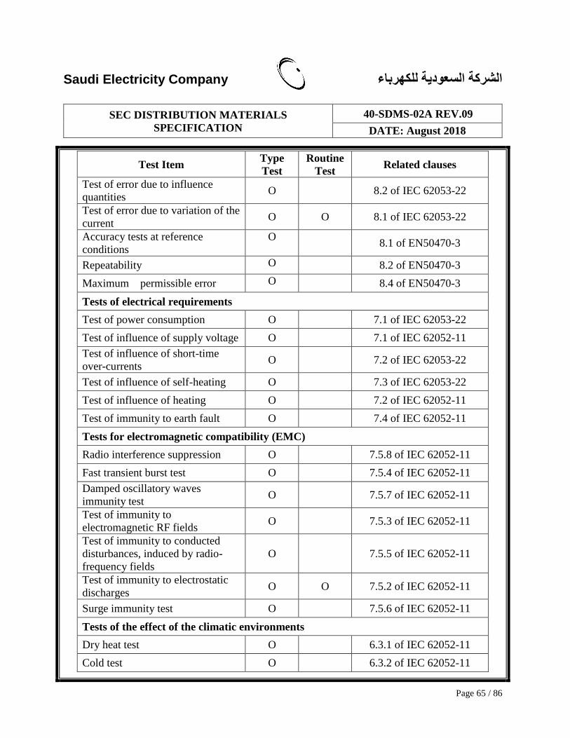
Saudi Electricity Company الشركة السعودية للكهرباء
SEC DISTRIBUTION MATERIALS
SPECIFICATION
40-SDMS-02A REV.09
DATE: August 2018
Page 65 / 86
Test Item Type
Test
Routine
Test Related clauses
Test of error due to influence
quantities O 8.2 of IEC 62053-22
Test of error due to variation of the
current O O 8.1 of IEC 62053-22
Accuracy tests at reference
conditions
O 8.1 of EN50470-3
Repeatability O 8.2 of EN50470-3
Maximum permissible error O 8.4 of EN50470-3
Tests of electrical requirements
Test of power consumption O 7.1 of IEC 62053-22
Test of influence of supply voltage O 7.1 of IEC 62052-11
Test of influence of short-time
over-currents O 7.2 of IEC 62053-22
Test of influence of self-heating O 7.3 of IEC 62053-22
Test of influence of heating O 7.2 of IEC 62052-11
Test of immunity to earth fault O 7.4 of IEC 62052-11
Tests for electromagnetic compatibility (EMC)
Radio interference suppression O 7.5.8 of IEC 62052-11
Fast transient burst test O 7.5.4 of IEC 62052-11
Damped oscillatory waves
immunity test O 7.5.7 of IEC 62052-11
Test of immunity to
electromagnetic RF fields O 7.5.3 of IEC 62052-11
Test of immunity to conducted
disturbances, induced by radio-
frequency fields
O 7.5.5 of IEC 62052-11
Test of immunity to electrostatic
discharges O O 7.5.2 of IEC 62052-11
Surge immunity test O 7.5.6 of IEC 62052-11
Tests of the effect of the climatic environments
Dry heat test O 6.3.1 of IEC 62052-11
Cold test O 6.3.2 of IEC 62052-11

Saudi Electricity Company الشركة السعودية للكهرباء
SEC DISTRIBUTION MATERIALS
SPECIFICATION
40-SDMS-02A REV.09
DATE: August 2018
Page 66 / 86
Test Item Type
Test
Routine
Test Related clauses
Damp heat, cyclic test O 6.3.3 of IEC 62052-11
Solar radiation test O 6.3.4 of IEC 62052-11
Mechanical tests
Vibration test O 5.2.2.3 of IEC 62052-11
Shock test O 5.2.2.2 of IEC 62052-11
Spring hammer test O 5.2.2.1 of IEC 62052-11
Terminals (blocks) O O 5.4 of IEC 62052-11
Tests of protection against
penetration of dust and water O 5.9 of IEC 62052-11
Test of resistance to heat and fire O 5.8 of IEC 62052-11
Accelerated Reliability Testing O 16.9.22
Prevention of PLC Signal
Attenuation and Distortion O 7.10.10
Terminal coating test O
Salt spary test O IEC 60068-2-52
Input Output Requirement
Display O O 8.1
Power Supply for External
Communication Devices O O 8.3
Optical Interface O O 8.4.1
RS-485 Communication Interfaces O O 8.4.2
In-home Display (IHD) Support O O 8.4.3
Protocol O O 8.5
Output relay O O 8.6
kWH Pulse Output and EOI Pulse
Output O O 8.7
Functional tests
Total Energy registers O O 9.1.2
TOU registers O O 9.1.3
Current/last Average Demand O O 9.1.4
Maximum Demand O O 9.1.5
Cumulative Maximum Demand O O 9.1.6

Saudi Electricity Company الشركة السعودية للكهرباء
SEC DISTRIBUTION MATERIALS
SPECIFICATION
40-SDMS-02A REV.09
DATE: August 2018
Page 67 / 86
Test Item Type
Test
Routine
Test Related clauses
Load Profile O O 9.1.7
Billing periods O O 9.1.8
Special day settings O O OBIS 6.7
Reset Function and Historical Data
Recording O O 9.2
Real Time Clock and Calendar O O 9.3 (for clock accuracy test,
IEC 62052-21 / 62054-21)
Energy storage device O O 9.4
Data Retention O O 9.5
Instantaneous Measurements O O 9.6
Display Function O O 9.7
Security Access O O 9.8
Data transport security O O 9.9
Anti-tampering/Anti-fraud O O 9.10
Magnetic Interference Tampering
Protection O O 9.11
Abnormal status/Event/Alarm O O 9.12
Auto Registration O 9.13
Global Meter Reset O 9.14
Meter Password Reset
Management O 9.15
CT by-Pass detectio O O 9.16
Default Settings O 10
Marking of Meters
Name-plate O O 12.
Terminal Cover / Meter Cover O O 6.3, 6.4, 12
Packing O O 12
Interoperability O O 14.9
DC12V Output Noise Level
Measurement (for Gateway) O O 7.10.10.4(under -70dBm)
PLC Signal Insertion Loss (RS-
485 Signal Port) O O 7.10.10.20 (under 5dBm)

Saudi Electricity Company الشركة السعودية للكهرباء
SEC DISTRIBUTION MATERIALS
SPECIFICATION
40-SDMS-02A REV.09
DATE: August 2018
Page 68 / 86
Test Item Type
Test
Routine
Test Related clauses
Test Method O O 16
16. TESTING METHOD
16.1. Structure Inspection
16.1.1. The meters selected for inspection shall be visually examined in order
to verify that they belong to the same type, that their specified
markings are correct and that none of them shows signs of damage.
The meters shall be in conformity with the type approval and they shall
have the same voltage and current characteristics.
16.1.2. The inspection test for structure, shape, size, color, etc. shall be
performed for Clause 6, 8.1 and DRAWING No. SEC/KWH-S-01, 02,
03 and 04. If it is difficult to perform the inspection test with a certain
item required for material analysis or component destroy, the item can
be tested with the verifiable documents submitted by the manufacturer.
16.1.3. LCD display shall be checked as per clause 8.1 and DRAWING No.
SEC/KWH-S-04.
16.1.4. Energy storage device shall be checked as per clause 6.1.4, 9.3, 9.4
and with technical specification of the energy storage device
manufacturer.
16.2. Insulation Performance Test
16.2.1. Impulse voltage test: impulse waveform 1.2/50㎲, source impedance
at 40~50Ω / 400~420J and voltages 8kV for CT meter s and 6kV for
CT-VT meters .
16.2.2. AC voltage test: frequency 60Hz, test voltage 2kV, applied for 1
minute and as per clause 7.4 of IEC 62053-22.
16.3. Accuracy Test
16.3.1. Test of starting and no-load condition: as per clause 8.3 of IEC 62053-
21 / IEC 62053-23.
16.3.2. Meter constant test: as per clause 8.3 of IEC 62053-22 (kWh, kVA) /
IEC 62053-23.
16.3.3. Limits of error due to variation of the current: as per clause 8.1 of IEC

Saudi Electricity Company الشركة السعودية للكهرباء
SEC DISTRIBUTION MATERIALS
SPECIFICATION
40-SDMS-02A REV.09
DATE: August 2018
Page 69 / 86
62053-22 / IEC 62053-23.
16.3.4. Limits of error due to influence quantities: as per clause 8.2 of IEC
62053-22 / IEC 62053-23.
※ Outside temperature range: -10°C to 75°C
※ If cosφ is 0.5, applied mean temperature coefficient is 0.1% / K.
16.3.5. The accuracy limit of apparent energy (Vrms x Irms) shall be the same
or less than the accuracy limit of active energy.
16.3.5.1. Accuracy test including the applied sub-harmonics
16.3.5.2. Accuracy test not including the applied sub-harmonics
16.3.5.3. Test with balanced load conditions
[Applied sub-harmonics for accuracy test]
※ Each degree sub-harmonics content (%) for voltage (V) and
current (A).
16.4. Electrical Requirements Test
16.4.1. Influence of supply voltage: as per clause 7.1 of IEC 62052-11.
16.4.2. Temperature rise: as per clause 4.1, 7.5 of this technical specification
and clause 7.2 of IEC 62052-11.
16.4.3. Power consumption: as per clause 7.1 of IEC 62053-22.
16.4.4. Influence of short-time overcurrents: as per clause 7.2 of IEC 62053-
22.
16.4.5. Influence of self-heating: as per clause 7.3 of IEC 62053-22.
16.5. Electromagnetic Compatibility (EMC) Test
16.5.1. Test of immunity to electrostatic discharges: as per clause 7.5.2 of IEC
62052-11.
16.5.2. Test of immunity to electromagnetic RF fields: frequency range
80~2700MHz, unmodulated test field strength 10V/m with operation
current, unmodulated test field strength 30V/m without operation
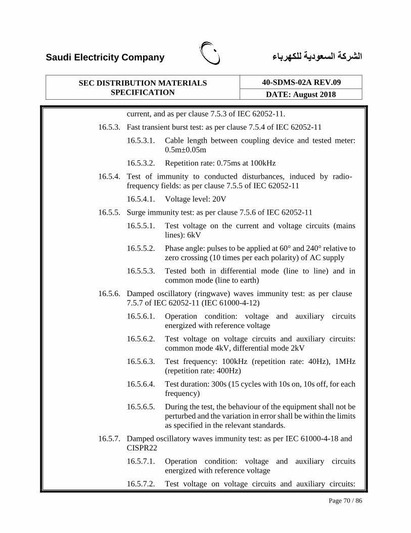
Saudi Electricity Company الشركة السعودية للكهرباء
SEC DISTRIBUTION MATERIALS
SPECIFICATION
40-SDMS-02A REV.09
DATE: August 2018
Page 70 / 86
current, and as per clause 7.5.3 of IEC 62052-11.
16.5.3. Fast transient burst test: as per clause 7.5.4 of IEC 62052-11
16.5.3.1. Cable length between coupling device and tested meter:
0.5m±0.05m
16.5.3.2. Repetition rate: 0.75ms at 100kHz
16.5.4. Test of immunity to conducted disturbances, induced by radio-
frequency fields: as per clause 7.5.5 of IEC 62052-11
16.5.4.1. Voltage level: 20V
16.5.5. Surge immunity test: as per clause 7.5.6 of IEC 62052-11
16.5.5.1. Test voltage on the current and voltage circuits (mains
lines): 6kV
16.5.5.2. Phase angle: pulses to be applied at 60° and 240° relative to
zero crossing (10 times per each polarity) of AC supply
16.5.5.3. Tested both in differential mode (line to line) and in
common mode (line to earth)
16.5.6. Damped oscillatory (ringwave) waves immunity test: as per clause
7.5.7 of IEC 62052-11 (IEC 61000-4-12)
16.5.6.1. Operation condition: voltage and auxiliary circuits
energized with reference voltage
16.5.6.2. Test voltage on voltage circuits and auxiliary circuits:
common mode 4kV, differential mode 2kV
16.5.6.3. Test frequency: 100kHz (repetition rate: 40Hz), 1MHz
(repetition rate: 400Hz)
16.5.6.4. Test duration: 300s (15 cycles with 10s on, 10s off, for each
frequency)
16.5.6.5. During the test, the behaviour of the equipment shall not be
perturbed and the variation in error shall be within the limits
as specified in the relevant standards.
16.5.7. Damped oscillatory waves immunity test: as per IEC 61000-4-18 and
CISPR22
16.5.7.1. Operation condition: voltage and auxiliary circuits
energized with reference voltage
16.5.7.2. Test voltage on voltage circuits and auxiliary circuits:

Saudi Electricity Company الشركة السعودية للكهرباء
SEC DISTRIBUTION MATERIALS
SPECIFICATION
40-SDMS-02A REV.09
DATE: August 2018
Page 71 / 86
common mode 2kV, differential mode 1kV
16.5.7.3. Test frequency: 100kHz, 1MHz, 3MHz (for common
mode), 100kHz, 1MHz (for differential mode)
16.5.7.4. Test duration: 300s (15 cycles with 10s on, 10s off, for each
frequency)
16.5.7.5. During the test, the behaviour of the equipment shall not be
perturbed and the variation in error shall be within the limits
as specified in the relevant standards.
16.5.7.6. Radio interference suppression test: as per clause 7.5.8 of
IEC 62052-11.
16.6. Climatic conditions and tests
16.6.1. Temperature range and relative humidity: as per clause 4 of this
technical specification and clause 6.1, 6.2 of IEC 62052-11.
16.6.2. Dry heat test: as per clause 4 of this technical specification and clause
6.3.1 of IEC 62052-11.
16.6.3. Cold test: as per clause 4 of this technical specification and clause 6.3.2
of IEC 62052-11.
16.6.4. Damp heat cyclic test: as per clause 4 of this technical specification
and clause 6.3.3 of IEC 62052-11.
16.7. Mechanical requirements and tests
16.7.1. General mechanical requirements: as per related clause of 01-SDMS-
01 and clause 5.1 of IEC 62052-11.
16.7.2. Case: as per as per clause 6.1 of this technical specification and clause
5.2 of IEC 62052-11.
16.7.3. Spring hammer test: as per clause 5.2.2.1 of IEC 62052-11.
16.7.4. Shock test: as per clause 5.2.2.2 of IEC 62052-11.
16.7.5. Vibration test: as per clause 5.2.2.3 of IEC 62052-11.
16.7.6. Window: as per clause 6.3, 6.4 of this technical specification and
clause 5.3 of IEC 62052-11.
16.7.7. Terminals – Terminal block(s) – Protective earth terminal: as per
clause 6.2 of this technical specification and clause 5.4 of IEC 62052-
11.
16.7.7.1. Certification of used material characteristics shall be
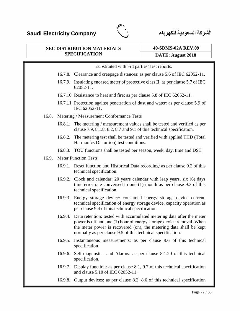
Saudi Electricity Company الشركة السعودية للكهرباء
SEC DISTRIBUTION MATERIALS
SPECIFICATION
40-SDMS-02A REV.09
DATE: August 2018
Page 72 / 86
substituted with 3rd parties’ test reports.
16.7.8. Clearance and creepage distances: as per clause 5.6 of IEC 62052-11.
16.7.9. Insulating encased meter of protective class II: as per clause 5.7 of IEC
62052-11.
16.7.10. Resistance to heat and fire: as per clause 5.8 of IEC 62052-11.
16.7.11. Protection against penetration of dust and water: as per clause 5.9 of
IEC 62052-11.
16.8. Metering / Measurement Conformance Tests
16.8.1. The metering / measurement values shall be tested and verified as per
clause 7.9, 8.1.8, 8.2, 8.7 and 9.1 of this technical specification.
16.8.2. The metering test shall be tested and verified with applied THD (Total
Harmonics Distortion) test conditions.
16.8.3. TOU functions shall be tested per season, week, day, time and DST.
16.9. Meter Function Tests
16.9.1. Reset function and Historical Data recording: as per clause 9.2 of this
technical specification.
16.9.2. Clock and calendar: 20 years calendar with leap years, six (6) days
time error rate conversed to one (1) month as per clause 9.3 of this
technical specification.
16.9.3. Energy storage device: consumed energy storage device current,
technical specification of energy storage device, capacity operation as
per clause 9.4 of this technical specification.
16.9.4. Data retention: tested with accumulated metering data after the meter
power is off and one (1) hour of energy storage device removal. When
the meter power is recovered (on), the metering data shall be kept
normally as per clause 9.5 of this technical specification.
16.9.5. Instantaneous measurements: as per clause 9.6 of this technical
specification.
16.9.6. Self-diagnostics and Alarms: as per clause 8.1.20 of this technical
specification.
16.9.7. Display function: as per clause 8.1, 9.7 of this technical specification
and clause 5.10 of IEC 62052-11.
16.9.8. Output devices: as per clause 8.2, 8.6 of this technical specification

Saudi Electricity Company الشركة السعودية للكهرباء
SEC DISTRIBUTION MATERIALS
SPECIFICATION
40-SDMS-02A REV.09
DATE: August 2018
Page 73 / 86
and clause 5.11 of IEC 62052-11.
16.9.9. Communication interfaces/devices: as per clause 8.3, 8.4, 8.5 of this
technical specification.
16.9.10. Security access: as per clause 9.8 of this technical specification.
16.9.11. Data transport security Access: as per clause 9.9 of this technical
specification.
16.9.12. Anti-tampering/Anti-fraud: as per clause 9.10 of this technical
specification.
16.9.13. Magnetic Interference Tampering Protection: as per clause 9.11 of this
technical specification.
16.9.14. Events/Alarms/Logs: as per clause 9.12 of this technical specification.
16.9.15. Auto Registration: as per clause 9.13 of this technical specification.
16.9.16. Global meter reset: as per clause 9.14 of this technical specification.
16.9.17. Meter password reset management: as per clause 9.15 of this technical
specification.
16.9.18. CT by-pass detection and CT open detection: as per clause 9.16 of this
technical specification.
16.9.19. Harmonics: as per clause 9.17 of this technical specification.
16.9.20. Other measurement and recording requirements: as per clause 9.17 of
this technical specification.
16.9.21. Marking and packing of meter: as per clause 12, 13 of this technical
specification and clause 5.12 of IEC 62052-11.
16.9.22. Accelerated Reliability Testing: it shall be conducted taking into
account the following reference temperature and moisture conditions:
Tmax = 75°C
RHmax=95%
Tm = 70°C
RHm = 85%
Tmin = 65°C
RHmin = 75%
Tuse = 40°C
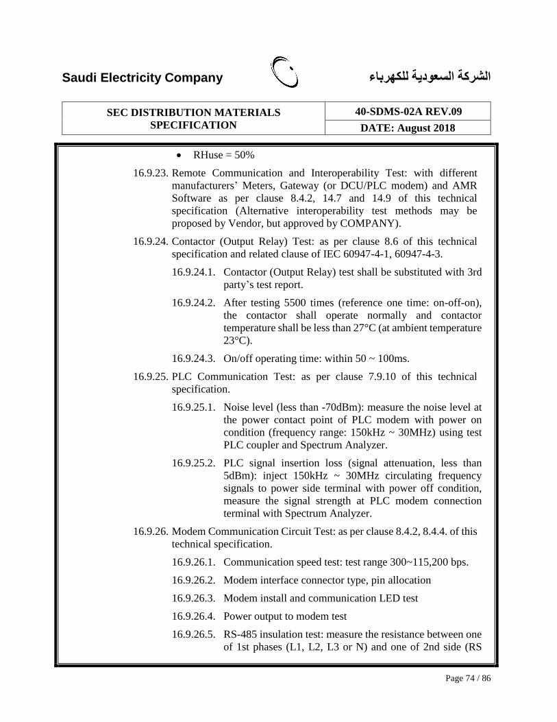
Saudi Electricity Company الشركة السعودية للكهرباء
SEC DISTRIBUTION MATERIALS
SPECIFICATION
40-SDMS-02A REV.09
DATE: August 2018
Page 74 / 86
RHuse = 50%
16.9.23. Remote Communication and Interoperability Test: with different
manufacturers’ Meters, Gateway (or DCU/PLC modem) and AMR
Software as per clause 8.4.2, 14.7 and 14.9 of this technical
specification (Alternative interoperability test methods may be
proposed by Vendor, but approved by COMPANY).
16.9.24. Contactor (Output Relay) Test: as per clause 8.6 of this technical
specification and related clause of IEC 60947-4-1, 60947-4-3.
16.9.24.1. Contactor (Output Relay) test shall be substituted with 3rd
party’s test report.
16.9.24.2. After testing 5500 times (reference one time: on-off-on),
the contactor shall operate normally and contactor
temperature shall be less than 27°C (at ambient temperature
23°C).
16.9.24.3. On/off operating time: within 50 ~ 100ms.
16.9.25. PLC Communication Test: as per clause 7.9.10 of this technical
specification.
16.9.25.1. Noise level (less than -70dBm): measure the noise level at
the power contact point of PLC modem with power on
condition (frequency range: 150kHz ~ 30MHz) using test
PLC coupler and Spectrum Analyzer.
16.9.25.2. PLC signal insertion loss (signal attenuation, less than
5dBm): inject 150kHz ~ 30MHz circulating frequency
signals to power side terminal with power off condition,
measure the signal strength at PLC modem connection
terminal with Spectrum Analyzer.
16.9.26. Modem Communication Circuit Test: as per clause 8.4.2, 8.4.4. of this
technical specification.
16.9.26.1. Communication speed test: test range 300~115,200 bps.
16.9.26.2. Modem interface connector type, pin allocation
16.9.26.3. Modem install and communication LED test
16.9.26.4. Power output to modem test
16.9.26.5. RS-485 insulation test: measure the resistance between one
of 1st phases (L1, L2, L3 or N) and one of 2nd side (RS
Saudi Electricity Company الشركة السعودية للكهرباء
SEC DISTRIBUTION MATERIALS
SPECIFICATION
40-SDMS-02A REV.09
DATE: August 2018
Page 75 / 86
485+ or RS485-) using Digital Multi Meter. The measured
resistance shall be ∞Ω (infinity).
17. OTHER REQUIREMENTS
17.1. Delivery Scope
17.1.1. Meter Hardware and Software, HHU, its fittings (communication
cables, screws, etc.).
17.1.2. Technical support for the quantity and inspection check, performance
test, integration test with Gateway (DCU) and AMR/AMM server and
trial operation.
17.1.3. Training for installation, operation and maintenance.
17.1.4. Others written in contract documents.
17.2. General Instructions
17.2.1. The Vendor is expected to have understood COMPANY’s whole
AMR/AMM system operation environment including used Gateway
(DCU), communication networks in KSA.
17.2.2. The Vendor shall be responsible for the technical support and the
presence to the Meter installation and inspection test (if requested).
17.2.3. The Vendor shall comply to this technical specification, “SCHA –
General Terms and Conditions”, contract documents, related laws and
regulations.
17.2.4. The Vendor shall perform the responsibilities of manufacturing,
factory inspection, delivery, training and warranty.
17.2.5. If there are differences of understanding the communication protocol
between the Meter and AMR/AMM server or there are required
protocol specifications not defined to be resolved for the
communications between the Meter and AMR/AMM server, the
Vendor shall accept COMPANY's interpretation of the issues and add
software functions (upgrade) to fulfill these requirements.
17.2.6. If there are differences of understanding the Gateway (DCU)
Saudi Electricity Company الشركة السعودية للكهرباء
SEC DISTRIBUTION MATERIALS
SPECIFICATION
40-SDMS-02A REV.09
DATE: August 2018
Page 76 / 86
communication protocol between the Meter and different
manufacturers’ meters the Vendor shall accept COMPANY's
interpretation of the issues and add software functions (upgrade) to
fulfill these requirements
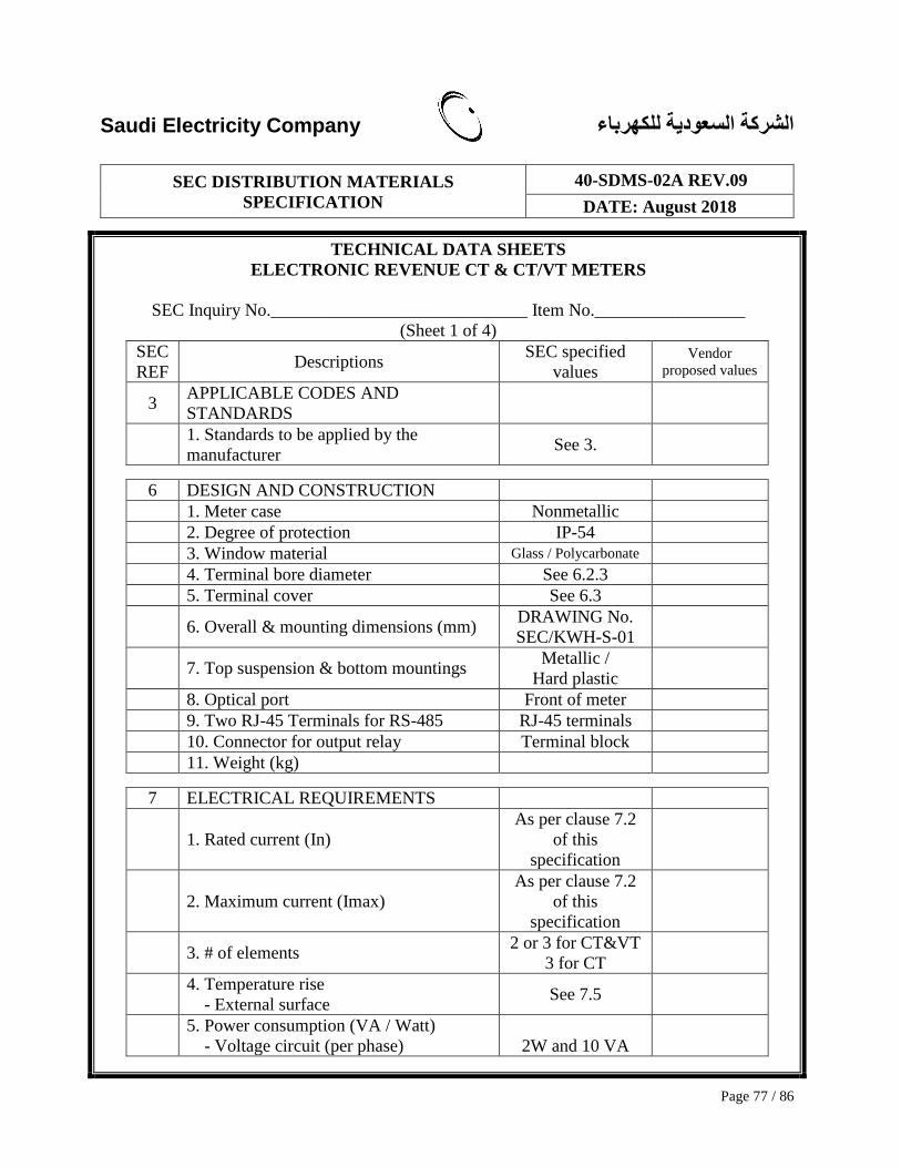
Saudi Electricity Company الشركة السعودية للكهرباء
SEC DISTRIBUTION MATERIALS
SPECIFICATION
40-SDMS-02A REV.09
DATE: August 2018
Page 77 / 86
TECHNICAL DATA SHEETS
ELECTRONIC REVENUE CT & CT/VT METERS
SEC Inquiry No._____________________________ Item No._________________
(Sheet 1 of 4)
SEC
REF Descriptions
SEC specified
values Vendor
proposed values
3 APPLICABLE CODES AND
STANDARDS
1. Standards to be applied by the
manufacturer See 3.
6 DESIGN AND CONSTRUCTION
1. Meter case Nonmetallic
2. Degree of protection IP-54
3. Window material Glass / Polycarbonate
4. Terminal bore diameter See 6.2.3
5. Terminal cover See 6.3
6. Overall & mounting dimensions (mm) DRAWING No.
SEC/KWH-S-01
7. Top suspension & bottom mountings Metallic /
Hard plastic
8. Optical port Front of meter
9. Two RJ-45 Terminals for RS-485 RJ-45 terminals
10. Connector for output relay Terminal block
11. Weight (kg)
7 ELECTRICAL REQUIREMENTS
1. Rated current (In)
As per clause 7.2
of this
specification
2. Maximum current (Imax)
As per clause 7.2
of this
specification
3. # of elements 2 or 3 for CT&VT
3 for CT
4. Temperature rise
- External surface See 7.5
5. Power consumption (VA / Watt)
- Voltage circuit (per phase)
2W and 10 VA
Saudi Electricity Company الشركة السعودية للكهرباء
SEC DISTRIBUTION MATERIALS
SPECIFICATION
40-SDMS-02A REV.09
DATE: August 2018
Page 78 / 86
- Current circuit
* CL = 0.5
1 VA
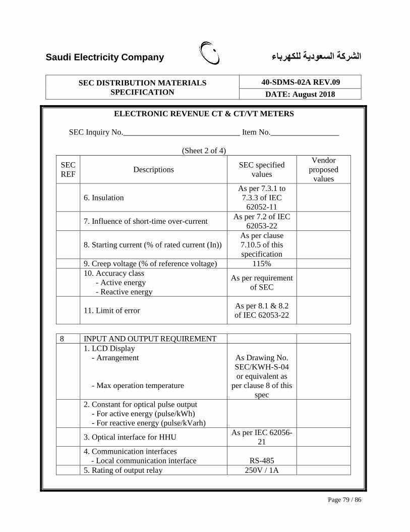
Saudi Electricity Company الشركة السعودية للكهرباء
SEC DISTRIBUTION MATERIALS
SPECIFICATION
40-SDMS-02A REV.09
DATE: August 2018
Page 79 / 86
ELECTRONIC REVENUE CT & CT/VT METERS
SEC Inquiry No._____________________________ Item No._________________
(Sheet 2 of 4)
SEC
REF Descriptions
SEC specified
values
Vendor
proposed
values
6. Insulation
As per 7.3.1 to
7.3.3 of IEC
62052-11
7. Influence of short-time over-current As per 7.2 of IEC
62053-22
8. Starting current (% of rated current (In))
As per clause
7.10.5 of this
specification
9. Creep voltage (% of reference voltage) 115%
10. Accuracy class
- Active energy
- Reactive energy
As per requirement
of SEC
11. Limit of error As per 8.1 & 8.2
of IEC 62053-22
8 INPUT AND OUTPUT REQUIREMENT
1. LCD Display
- Arrangement
- Max operation temperature
As Drawing No.
SEC/KWH-S-04
or equivalent as
per clause 8 of this
spec
2. Constant for optical pulse output
- For active energy (pulse/kWh)
- For reactive energy (pulse/kVarh)
3. Optical interface for HHU As per IEC 62056-
21
4. Communication interfaces
- Local communication interface
RS-485
5. Rating of output relay 250V / 1A

Saudi Electricity Company الشركة السعودية للكهرباء
SEC DISTRIBUTION MATERIALS
SPECIFICATION
40-SDMS-02A REV.09
DATE: August 2018
Page 80 / 86
ELECTRONIC REVENUE CT & CT/VT METERS
SEC Inquiry No._____________________________ Item No._________________
(Sheet 3 of 4)
SEC
REF Descriptions
SEC specified
values
Vendor
proposed values
9 FUNCTIONAL REQUIREMENTS
1. Energy measurement Required
2. Reverse energy indicator Required
3. # of TOU (Time of Use) rate At least 8 rates
4. # of TOU Channels 8 channels
5. Maximum demand measurement Required
6. Historical recording Required
7. LP (Load profile) recording Required
8. Real Time Clock ≤ ± 0.5 sec/day
8. Energy storage device
- Guaranteed life
- Whether replaceable?
- Energy storage device fail indicator
Required
20 years
Yes
Required
9. Energy storage device
- For maintaining LCD display and RTC
(without AC power and energy storage
device)
for at least 7 day
10. Data retention
- Type of memory used
- Guaranteed year of data retention
- Provision to retrieve data in case of
meter failure
As per clause 9.5
of this spec
11. Instantaneous measurement Required
12. Default settings Required
15 SUBMITTALS
1. Submittals as per this specification Yes/No
16 SEC DLMS/COSEM OBIS CODE
SPECIFICATION SUPPLEMENTARY
1. Submittals as per this specification Required

Saudi Electricity Company الشركة السعودية للكهرباء
SEC DISTRIBUTION MATERIALS
SPECIFICATION
40-SDMS-02A REV.09
DATE: August 2018
Page 81 / 86
ELECTRONIC REVENUE CT & CT/VT METERS
SEC Inquiry No._____________________________ Item No._________________
(Sheet 4 of 4)
A. ADDITIONAL TECHNICAL INFORMATION OR FEATURES SPECIFIED BY
COMPANY:
B. ADDITIONAL SUPPLEMENTARY DATA OR FEATURES PROPOSED BY
BIDDER/VENDOR/SUPPLIER:
C. OTHER PARTICULARS TO BE FILLED UP BY BIDDER/VENDOR/SUPPLIER:
D. LIST OF DEVIATIONS & CLAUSES TO WHICH EXCEPTION IS TAKEN BY THE
BIDDER/VENDOR/SUPPLIER:
MANUFACTURER OF
MATERIALS/EQUIPMENT VENDOR / SUPPLIER
Name of Company
Location and Office
address
Name and signature of
Authorized Representative
and Date
Official Seal / Stamp

Saudi Electricity Company الشركة السعودية للكهرباء
SEC DISTRIBUTION MATERIALS
SPECIFICATION
40-SDMS-02A REV.09
DATE: August 2018
Page 82 / 86
(1) This dimension shows a guideline to be fulfilled by manufacturers. The actual
dimension shall not exceed each length presented in this drawing.
(2) The drawing aspect is orientative and it’s open to the vendors
(3) The tolerance shall be 1mm for width and depth and 2mm for height

Saudi Electricity Company الشركة السعودية للكهرباء
SEC DISTRIBUTION MATERIALS
SPECIFICATION
40-SDMS-02A REV.09
DATE: August 2018
Page 83 / 86
CONNECTION ARRANGEMENT FOR 3 PHASE 4 WIRE CT OPERATED 133/230V OR 230/400V
ELECTRONIC KWH METER
DRAWING No. SEC/KWH-S-02
(1) Refer to clause 8.4.2 of RS-485 interface (21, 22) for further details. The RJ-45
power port shall be indicated in the plastic cover
(2) Refer to clause 8.4.3 of IHD interface (22) for further details. However the RJ-45 port
is not a mandatory requirement, but is preferable for COMPANY.

Saudi Electricity Company الشركة السعودية للكهرباء
SEC DISTRIBUTION MATERIALS
SPECIFICATION
40-SDMS-02A REV.09
DATE: August 2018
Page 84 / 86
(1) Refer to clause 8.4.2 of RS-485 interface (21, 22) for further details
(2) Refer to clause 8.4.3 of IHD interface (22) for further details. However the RJ-45
port is not a mandatory requirement, but is preferable for COMPANY.
(3) Refer to clause 8.7 of kWH-Pulse Output, EOI signals for further details
(4) In case of 3-element meter used for 3 phase 3 wire meter, the connection method
shall be the same externally to prevent possible mistakes of installation technicians.
CONNECTION ARRANGEMENT FOR 3 PHASE 3 WIRE CT-VT OPERATED 110V
ELECTRONIC KWH METER
DRAWING No. SEC/KWH-S-03

Saudi Electricity Company الشركة السعودية للكهرباء
SEC DISTRIBUTION MATERIALS
SPECIFICATION
40-SDMS-02A REV.09
DATE: August 2018
Page 85 / 86
(1) This display arrangement is presented as COMPANY recommendation. Different
presentation of display may be accepted through discussion with COMPANY.
(2) The tolerance shall be 1mm.
+