specifications for spiral pipe and fittings for spiral pipe and fittings minneapolis, mn 5850 main...
TRANSCRIPT

SPECIFICATIONS FOR
SPIRAL PIPE AND FITTINGS
MINNEAPOLIS, MN5850 Main Street N.E.
Minneapolis, MN 55432LOCALLY CALL: 763-572-0000TOLL FREE: 1-800-328-1966
FAX: 763-572-1100
ROCKFORD, IL5601 Sandy Hollow Road
Rockford, IL 61109LOCALLY CALL: 815-874-4600TOLL FREE: 1-866-504-4600
FAX: 815-874-9979
MINNEAPOLIS, MNMINNEAPOLIS, MN5850 Ma5850 Main Strin Street N.E.eet N.E.
Minneapolis, MN 55432Minneapolis, MN 55432LOCALLY CALL: 763-572-0000LOCALLY CALL: 763-572-0000TOLL FREE: 1-800-328-1966TOLL FREE: 1-800-328-1966
FAX: 763-572-1100FAX: 763-572-1100
ROCKFORD, ILROCKFORD, IL56015601 Sandy Sandy Hollow Road Hollow Road
Rockford, IL 61109Rockford, IL 61109

Corporate Headquarters
SHEET METAL CONNECTORS, INC.5850 MAIN STREET N.E. • MINNEAPOLIS, MINNESOTA 55432
Toll Free: 800-328-1966 Local: 763-572-0000 Fax: 763-572-1100www.smcduct.com
Manufacturing Facilities5850 Main Street N.E. 5601 Sandy Hollow RoadMinneapolis, MN 55432 Rockford, IL 61109LOCAL: 763-572-0000 LOCAL: 815-874-4600TOLL FREE: 1-800-328-1966 TOLL FREE: 1-866-504-4600FAX: 763-572-1100 FAX: 815-874-9979
Sheet Metal Connectors, Inc. is proud to be a member or affiliatedwith the following associations;
Sheet Metal Workers’ International AssociationWashington, DC
Sheet Metal Air Conditioning Contractors’National AssociationChantilly, VA
SPIDASpiral Duct Manufacturers AssociationIrmo, SC
SMACNA Testing & Research InstituteChantilly, VA

1Single-Wall Spiral Pipe & Fittings
Sheet Metal Connectors, Inc. (SMC) Single Wall Pipe and Fittingswith Complete Seal, E-Z Flange and Barrel Clamp or Standard Slip Connection
Single-Wall Spiral PipeSheet Metal Connectors, Inc. spiral pipe is formed from a coil of metal into a rigid steel tube with a 4-ply spiral lockseam. It has a smooth interior for low friction loss with the grooved seam entirely on the outside. This pipe has a resistance to crushing approximately 2 1/2 times that of longitudinal lockseam or welded pipe. Optional corrugations are available which increase the rigidity of the pipe by approximately 300%. Pipe sections can be joined together by an Complete Seal Spiral Pipe Connector, E-Z Flange with Barrel Clamp, E-Z Flange Jr. with Barrel Clamp, Standard Spiral Pipe Connector, or Companion Angle Rings.
May 2013
Single-Wall Materials DIAMETER MATERIAL THICKNESS ASTM TYPE LENGTH
3” - 96” Galvanized 26 - 14 gauge A-653 G60-G90 1’ – 20’, 10’ Standard
3” - 96” Paint Grip 24 - 18 gauge A-653 A60 1’ – 20’, 10’ Standard
3” - 96” PVS* 24 - 16 gauge A-653 4 x 1, 4 x 4 1’ – 20’, 10’ Standard
3” - 60”** Aluminum .032 - .063 B-316 3003 H-14 1’ – 20’, 10’ Standard
3” - 60”** Stainless Steel 24 - 18 gauge A-240 304 or 316 1’ – 20’, 10’ Standard
*PVS specification book available** Call factory for sizes over 60” in diameter.
Note: SMACNA Testing and Research Institute verified that Sheet Metal Connectors, Inc. shop standards comply with the 2005-3rd edition of the SMACNA HVAC Duct Construction Standards.
5" 5"
5
5" 5"
5
5" 5"
5
Lateral section of 4-ply pressure-proof spiral seam.
Lateral section of grooved seam with optional corrugated grooves.
Optional culvert groove.
5”
5”
5”
Single-Wall FittingsSMC spiral fittings are manufactured with an elbow lock seam, lap
seam (i.e. stitch weld, riveted, tack weld or solid weld), standing
seam or butt weld seam. These may be with or without duct
sealant.
All fittings can be manufactured with:• Complete Seal Spiral Pipe System – 6” to 24” Diameter (even sizes)
• E-Z Flange Jr. with Barrel Clamp – 6” to 24” Diameter
• E-Z Flange with Barrel Clamp – 26” to 96” Diameter
• Standard Spiral Pipe End
• Companion Angle Ring
Elbow Lock Seam
Riveted Lap Seam
Standing Seam
Butt Weld Seam
Stich Weld

2
Companion Angle Rings -Pressed and RolledCompanion angle rings are for end connections whenever a smooth interior surface or intermediate stiffening is required. Rings are manufactured from mild steel. Companion angle rings can be factory installed or shipped loose. Companion angle rings can be attached by solid weld, tack weld, or van stone connection. See companion angle ring size chart on page 20.
Single-Wall ConnectorsComplete Seal Fittings -6” to 24” DiameterComplete Seal fittings are manufactured from galvanized steel meeting spec ASTM A-653 (Lockforming quality). They feature a double legged EPDM gasket which creates a virtually airtight connection when slipped into spiral pipe. The gasket i s mechan ica l l y a t t ached to the f i t t i ng w i th a 180 degree hemmed edge. This hem gives added rigidity to the fittings, ensures that the gasket will never slip out of place and makes a safe rounded edge for the installer.*Complete Seal is currently available on Galvanized Fittings only.
E-Z Flange with Barrel Clamp -26” to 96” DiameterThe E-Z flange with barrel clamp can be factory installed or shipped loose for field installation. A set consists of two E-Z flanges and one barrel clamp. For field installation the installer attaches the E-Z flange to the pipe and fittings. Next the installer applies the gasket to one flange, mates the two flanges together and attaches the barrel clamp. Sheet Metal Connectors can also install E-Z flanges. Flanges are spot welded and internally sealed on all ends of the spiral pipe and fittings.
E-Z Flange Jr. with Barrel Clamp -6” to 24” DiameterThe E-Z flange jr. is a 5/8” flange turned out 90° on each end of the spiral pipe and fittings. The installer applies a gasket on one flange, mates the two flanges together, and attaches the barrel clamp. For field cuts a 5/8” flanged sleeve is available. Trim the spiral pipe to the measured length and attach the sleeve.
Standard Spiral Pipe ConnectorPipe to Pipe connections are made by using a fitting size coupling that slips inside the mating pipe sections. A stop bead runs around the middle of the coupling to center the coupling in the connection. Secure the connection by installing sheet metal screws through the outer shell of the duct, 1/2 inch from the stop bead.

3Weight and Gauge Chart
Internal PressureCollapsing Pressure various gauges of spiral tubing
26 24 22 20 18 16Gauge Gauge Gauge Gauge Gauge Gauge
Diam. lbs./ft. lbs./ft. lbs./ft. lbs./ft. lbs./ft. lbs./ft.
3” 0.8 1.1 1.3 1.54” 1.1 1.4 1.7 2.05” 1.4 1.7 2.1 2.5 3.2 4.06” 1.6 2.0 2.5 3.0 3.9 4.57” 1.9 2.4 2.9 3.4 4.6 5.68” 2.1 2.8 3.3 3.9 5.2 6.39” 2.4 3.1 3.8 4.4 5.9 7.2
10” 2.6 3.4 4.2 4.9 6.5 7.911” 2.9 3.8 4.6 5.4 7.1 8.712” 3.2 4.1 5.0 5.9 7.8 9.513” 4.5 5.4 6.4 8.5 10.214” 4.8 5.8 6.9 9.1 11.115” 5.1 6.2 7.4 9.8 11.916” 5.5 6.6 7.8 10.4 12.717” 5.8 7.1 8.3 11.1 13.418” 6.1 7.5 8.8 11.7 14.220” 6.8 8.3 9.8 13.0 15.822” 7.5 9.1 10.8 14.3 17.424” 8.2 9.9 11.7 15.6 19.026” 10.8 12.7 16.9 20.628” 11.6 13.7 18.2 22.230” 12.4 14.6 19.5 23.832” 13.3 15.6 20.8 25.434” 14.1 16.6 22.0 26.936” 14.9 17.6 23.3 28.538” 18.5 24.6 30.140” 19.5 25.9 31.742” 20.5 27.2 33.344” 21.5 28.5 34.946” 22.5 29.8 36.448” 23.4 31.1 38.050” 24.5 32.4 39.652” 33.7 41.354” 34.8 42.956” 36.3 44.558” 37.4 46.060” 38.9 47.3
Standard gauges in boxed area, weights may vary slightly.
26 24 22 20 18 Diam. Gauge Gauge Gauge Gauge Gauge 3” 420 535 650 765 995 4” 308 392 475 560 728 5” 238 303 369 435 566 6” 199 252 308 363 473 7” 169 216 262 309 403 8” 145 186 224 264 344 9” 127 161 196 230 299 10” 113 144 177 208 271 12” 93 118 145 171 223 14” 76 100 120 142 185 16” 68 86 103 122 162 18” 75 91 104 136 20” 66 81 96 125 22” 60 72 85 111 24” 66 78 101 26” 61 72 94 28” 55 65 85 30” 51 60 78 32” 47 56 73 34” 52 68 36” 48 65 38” 45 59 40” 42 55 42” 39 51 44” 47 46” 44 48” 41 50” 39
All tube diameters in inches. All pressure in PSI.
1 PSI = 27.678 H20
26 24 22 20 18 16 Diam. Gauge Gauge Gauge Gauge Gauge Gauge
6” 220.4 8” 69.2 121.2
10” 34.6 110.6 691.712” 22.0 55.1 249.2 1107.014” 15.3 38.5 110.6 456.6 2767.716” 11.0 27.5 105.1 236.2 1383.8 5258.618” 9.0 20.8 53.9 149.6 664.1 2214.120” 7.8 16.5 38.5 99.6 332.2 1245.622” 7.2 14.1 30.3 72.0 221.2 692.124” 5.5 11.8 24.8 55.5 155.1 387.426” 5.1 9.8 20.8 44.0 110.6 290.528” 4.7 8.6 18.1 35.8 88.5 243.730” 4.3 8.2 15.3 30.3 69.2 166.132” 6.6 13.7 26.3 58.2 128.734” 22.0 48.4 103.936” 5.5 11.0 20.4 42.9 85.838” 17.7 37.4 72.040” 4.3 9.8 16.5 33.0 62.242” 9.0 15.3 29.1 53.944” 13.7 26.3 47.246” 12.5 23.6 41.348” 11.8 22.0 37.450” 11.0 19.2 34.660” 14.9 24.8
.036 PSI = 1 inch H20
Internal negative pressure in inches of water.
Positive PressureBursting Pressure various gauges of spiral tubing
These tables are given only as a courtesy. Sheet Metal Connectors is not responsible for any results listed on these charts.
CLOSE CELL NEOPRENE GASKETNeoprene 1/4” x 1/2” (50’ rolls - 1500’ per box) E-Z Flange Jr.
Neoprene 1/4” x 3/4” (50’ rolls - 1500’ per box) E-Z Flange & TDC

4Two Piece Pressed Solid Welded Elbows
Pressed elbows and angles are resistance welded with copper on both the heel and throat. All pressed fittings are manufactured from extra deep drawing steel (EDDS) in accordance with ASTM-A653. Pressed fittings are precision drawn, tolerances must be within + or - .002 thickness to assure a quality product at all times. All pressed fittings are made of 24 Ga. or 22 Ga. Galvanized material with a G60 or better coating thickness and are chemically treated to retard white rust.
Diam. 90º 45º
3” 4 1/2” 4 1/2”4” 6” 6”5” 7 1/2” 7 1/2”6” 9” 9”7” 10 1/2” 10 1/2”8” 12” 12”9” 13 1/2” 13 1/2”
10” 15” 15”12” 18” 18”14” 21” 21”
Centerline ThroatRadius Chart
Full Sweep Standing Seam Elbows8”-30” will be a 5 gore one piece standard throat construction. 32” and larger in diameter 90 degree full sweep (1.5 x CL) elbows are fabricated using two 45 degree angles connected with an E-Z flange and barrel clamp unless otherwise specified.
Standard Throats
8” thru 18” 8” Throat 20” thru 40” 10” Throat 42” thru 60” * 20” Throat
Standing Seam Elbows & AnglesStanding Seam Elbows and AnglesStanding Seam fittings work well for medium pressure applications and offer an alternative to welded elbows and angles. These are available from 8” through 60” diameters and fabricated as heavy as 16 gauge. Other diameters and throat radiuses are available.* 42” and larger diameter 90 degree elbows are fabricated using two 45 degree angles connected with an E-Z Flange and Barrel Clamp unless otherwise specified.
All Fittings are 1.75” from Bead to End of Fitting.
All Fittings are 1.75” from Bead to End of Fitting.

5Adjustable Elbows & Angles
90° Throat and Gauge Chart26 24 22 26 24 22
Diam. Gauge Gauge Gauge Diam. Gauge Gauge Gauge
3” 1” 1” N/A 13” 3” 3” 3”4” 1 1/2” 1 1/2” 1 1/2” 14” N/A 3” 3”5” 1 1/2” 1 1/2” 1 1/2” 15” N/A 3” 3”6” 1 1/2” 1 1/2” 1 1/2” 16” N/A 3” 3”7” 1 1/2” 1 1/2” 1 1/2” 18” N/A 3” 3”8” 2” 2” 2” 20” N/A 3” 3”9” 2” 2” 2” 22” N/A N/A 5”10” 2” 2” 2” 24” N/A N/A 5”11” 3” 3” 3” 26” N/A N/A 5”12” 2 1/2” 2 1/2” 2 1/2” 28” N/A N/A 5”
D
D
D
D
Full sweep elbows and angles are available up to 16” diameter.
45° Throat and Gauge Chart26 24 22 26 24 22
Diam. Gauge Gauge Gauge Diam. Gauge Gauge Gauge
3” 3” 3” N/A 13” 5” 5” 5”4” 3” 3” 3” 14” N/A 5” 5”5” 4” 4” 4” 15” N/A 5” 5”6” 4” 4” 4” 16” N/A 5” 5”7” 5” 5” 5” 18” N/A 5” 5”8” 5” 5” 5” 20” N/A 5” 5”9” 5” 5” 5” 22” N/A N/A 5”
10” 5” 5” 5” 24” N/A N/A 5”11” 5” 5” 5” 26” N/A N/A 5”12” 5” 5” 5” 28” N/A N/A 5”
Welded Gored Elbows & Angles
Standard Elbows and Angles are fabricated from 20 gauge galvanized material. Other diameters, throat radiuses and gauges are available, please consult factory.
52” and larger in diameter 90 degree full sweep (1.5 x CL) elbows are fabricated using two 45 degree angles connected with an E-Z flange and barrel clamp unless otherwise specified.

6
90° TeeDimensions to be listed as follows: A, B, CL = “C” + 4”
All Fittings are 1.75” from Bead to End of Fitting.
Tee with ReducerDimensions to be listed as follows: A, B, CL = “C” + 4”L.R.: Refer to page 9
All Fittings are 1.75” from Bead to End of Fitting.
CrossDimensions to be listed as follows: A, B, C, DL = Largest of “C” or “D” + 4”
All Fittings are 1.75” from Bead to End of Fitting.
Cross with ReducerDimensions to be listed as follows: A, B, C, DL = Largest of “C” or “D” + 4”L.R.: Refer to page 9
All Fittings are 1.75” from Bead to End of Fitting.

7Conical Tee Dimensions to be listed as follows: A, B, CL = C + 5”
All Fittings are 1.75” from Bead to End of Fitting.
Conical Tee with ReducerDimensions to be listed as follows: A, B, CL = C + 5”L.R.: Refer to page 9
All Fittings are 1.75” from Bead to End of Fitting.
Conical CrossDimensions to be listed as follows: A, B, C, DL = Larger of “C” or “D” + 5”
All Fittings are 1.75” from Bead to End of Fitting.
Conical Cross with ReducerDimensions to be listed as follows: A, B, C, DL = Larger of “C” or “D” + 5”L.R.: Refer to page 9
All Fittings are 1.75” from Bead to End of Fitting.

8Lateral Dimensions to be listed as follows: A, B, CL = (1.414 x C) + 4”
All Fittings are 1.75” from Bead to End of Fitting.
Lateral with ReducerDimensions to be listed as follows: A, B, CL = (1.414 x C) + 4”L.R.: Refer to page 9
All Fittings are 1.75” from Bead to End of Fitting.
Lateral CrossDimensions to be listed as follows: A, B, C, DL = 1.414 x (Larger of “C” or “D”) + 4”
All Fittings are 1.75” from Bead to End of Fitting.
Lateral Cross with ReducerDimensions to be listed as follows: A, B, C, DL = 1.414 x (Larger of “C” or “D”) + 4”L.R.: Refer to page 9
All Fittings are 1.75” from Bead to End of Fitting.

9Bullnose Tee (Bullhead)Dimensions to be listed as follows: A, B, CL.R.: Refer to page 9
All Fittings are 1.75” from Bead to End of Fitting.
Pair of Pants (Wye Branch)Dimensions to be listed as follows: A, B, C
All Fittings are 1.75” from Bead to End of Fitting.
OffsetDimensions to be listed as follows: A, O, L
All Fittings are 1.75” from Bead to End of Fitting.
LR Value for Tees and Crosses Size Reduction LR 1 4.75 2 5.75 3 5.75 4 7.75 5 8.75 6 9.75 7 13.25 8 14.25 9 16.25 10 17.25 11 18.25
Size Reduction LR 12 20.25 13 21.25 14 22.25 15 25.25 16 25.25 17 28.25 18 28.25 19 29.25 20 31.25 21 32.25 22 33.25
* Add 1.5” to LR Value for Diameters over 18”

10
90° Swedged SaddleDimensions to be listed as follows: A on B
All Fittings are 1.75” from Bead to End of Fitting.
45° Swedged SaddleDimensions to be listed as follows: A on B
All Fittings are 1.75” from Bead to End of Fitting.
90° Full SaddleDimensions to be listed as follows: A on B
All Fittings are 1.75” from Bead to End of Fitting.
45° Full SaddleDimensions to be listed as follows: A on B
All Fittings are 1.75” from Bead to End of Fitting.

11
A
3.5”
B
A
6"
1"
1"
C
90° Conical Swedge SaddleDimensions to be listed as follows: A on BB= A + 1”
All Fittings are 1.75” from Bead to End of Fitting.
90° Shoe TapDimensions to be listed as follows: A on BC=A+3”
All Fittings are 1.75” from Bead to End of Fitting.
Register TakeoffsDimensions to be listed as follows: A, B on C(Order Takeoffs by Register Size Only)
End Cap (Plug)Dimensions to be listed as follows: A, equal diameter
All Fittings are 1.75” from Bead to End of Fitting.
Connector (Coupling)Dimensions to be listed as follows:A, equals diameter
All Fittings are 1.75” from Bead to End of Fitting.
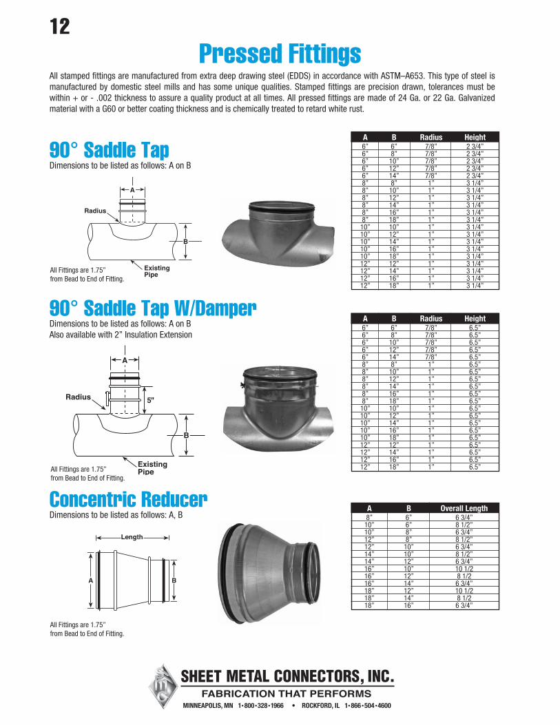
90° Saddle TapDimensions to be listed as follows: A on B
90° Saddle Tap W/DamperDimensions to be listed as follows: A on BAlso available with 2” Insulation Extension
Concentric ReducerDimensions to be listed as follows: A, B
12
Radius
ExistingPipe
Pressed FittingsAll stamped fittings are manufactured from extra deep drawing steel (EDDS) in accordance with ASTM–A653. This type of steel is manufactured by domestic steel mills and has some unique qualities. Stamped fittings are precision drawn, tolerances must be within + or - .002 thickness to assure a quality product at all times. All pressed fittings are made of 24 Ga. or 22 Ga. Galvanized material with a G60 or better coating thickness and is chemically treated to retard white rust.
A B Radius Height 6” 6” 7/8” 2 3/4” 6” 8” 7/8” 2 3/4” 6” 10” 7/8” 2 3/4” 6” 12” 7/8” 2 3/4” 6” 14” 7/8” 2 3/4” 8” 8” 1” 3 1/4” 8” 10” 1” 3 1/4” 8” 12” 1” 3 1/4” 8” 14” 1” 3 1/4” 8” 16” 1” 3 1/4” 8” 18” 1” 3 1/4” 10” 10” 1” 3 1/4” 10” 12” 1” 3 1/4” 10” 14” 1” 3 1/4” 10” 16” 1” 3 1/4” 10” 18” 1” 3 1/4” 12” 12” 1” 3 1/4” 12” 14” 1” 3 1/4” 12” 16” 1” 3 1/4” 12” 18” 1” 3 1/4”
A B Radius Height 6” 6” 7/8” 6.5” 6” 8” 7/8” 6.5” 6” 10” 7/8” 6.5” 6” 12” 7/8” 6.5” 6” 14” 7/8” 6.5” 8” 8” 1” 6.5” 8” 10” 1” 6.5” 8” 12” 1” 6.5” 8” 14” 1” 6.5” 8” 16” 1” 6.5” 8” 18” 1” 6.5” 10” 10” 1” 6.5” 10” 12” 1” 6.5” 10” 14” 1” 6.5” 10” 16” 1” 6.5” 10” 18” 1” 6.5” 12” 12” 1” 6.5” 12” 14” 1” 6.5” 12” 16” 1” 6.5” 12” 18” 1” 6.5”
A B Overall Length 8” 6” 6 3/4” 10” 6” 8 1/2” 10” 8” 6 3/4” 12” 8” 8 1/2” 12” 10” 6 3/4” 14” 10” 8 1/2” 14” 12” 6 3/4” 16” 10” 10 1/2 16” 12” 8 1/2 16” 14” 6 3/4” 18” 12” 10 1/2 18” 14” 8 1/2 18” 16” 6 3/4”
All Fittings are 1.75” from Bead to End of Fitting.
All Fittings are 1.75” from Bead to End of Fitting.
All Fittings are 1.75” from Bead to End of Fitting.

13
Eccentric ReducerDimensions to be listed as follows: A,BLR = See Chart
LR
AB
Size Reduction LR 1 6 2 8.5 3 11 4 13.5 5 16 6 18.5 7 21 8 23.5 9 26 10 28.5 11 31 12 33.5 14 38.5 16 43.5 18 48.5 20 53.5
Size Reduction LR 1 6.5 2 & 3 7.5 4 9.5 5 10.5 6 11.5 7 13.5 8 14.5 9 16.5 10 17.5 11 18.5 12 20.5 13 21.5 14 22.5 15 & 16 25.5 17 & 18 28.5 19 29.5 20 31.5 21 32.5 22 33.5
Concentric ReducerDimensions to be listed as follows: A, BLR = See Chart
All Fittings are 1.75” from Bead to End of Fitting.
All Fittings are 1.75” from Bead to End of Fitting.
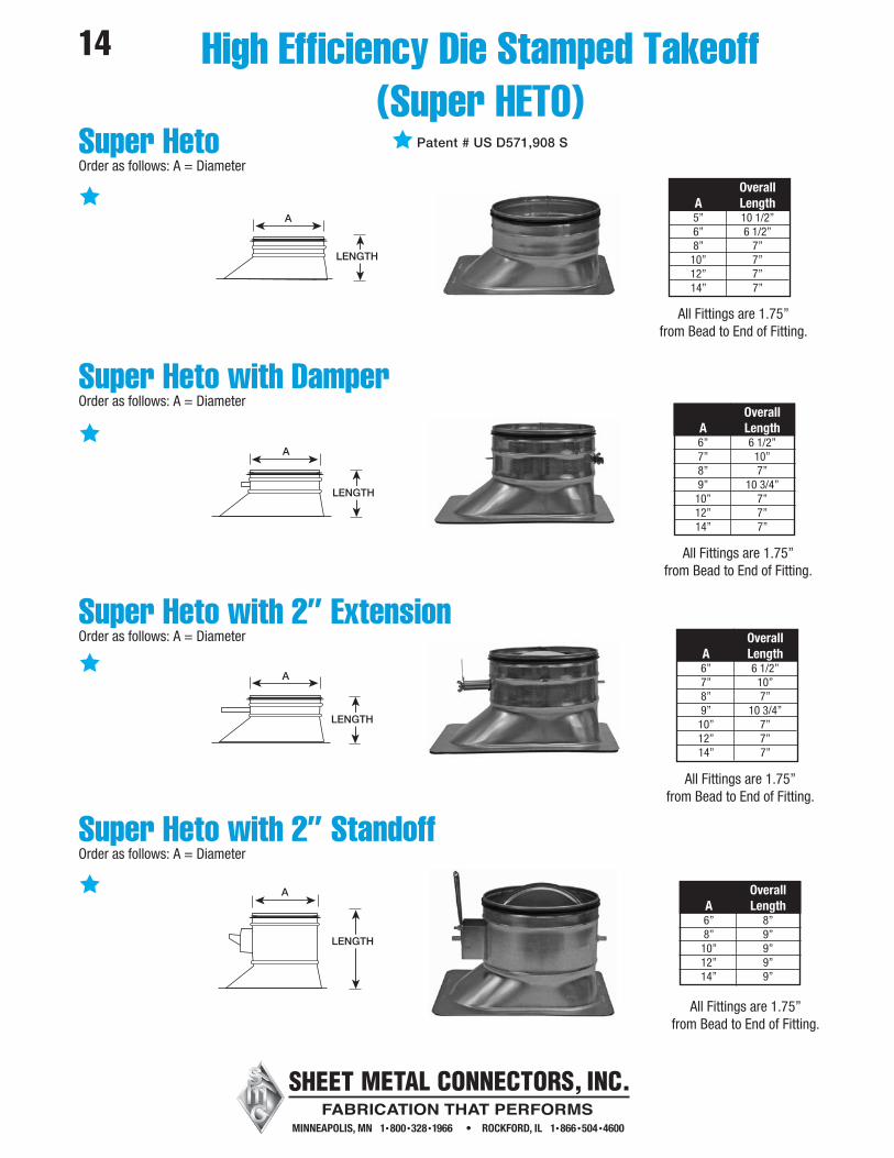
14 High Efficiency Die Stamped Takeoff(Super HETO)
Super HetoOrder as follows: A = Diameter
Super Heto with DamperOrder as follows: A = Diameter
Super Heto with 2” ExtensionOrder as follows: A = Diameter
Super Heto with 2” StandoffOrder as follows: A = Diameter
Overall A Length 5” 10 1/2” 6” 6 1/2” 8” 7” 10” 7” 12” 7” 14” 7”
Overall A Length 6” 6 1/2” 7” 10” 8” 7” 9” 10 3/4” 10” 7” 12” 7” 14” 7”
Overall A Length 6” 6 1/2” 7” 10” 8” 7” 9” 10 3/4” 10” 7” 12” 7” 14” 7”
Overall A Length 6” 8” 8” 9” 10” 9” 12” 9” 14” 9”
All Fittings are 1.75” from Bead to End of Fitting.
All Fittings are 1.75” from Bead to End of Fitting.
All Fittings are 1.75” from Bead to End of Fitting.
All Fittings are 1.75” from Bead to End of Fitting.
Patent # US D571,908 S

15
E-Z Tap Collars with 2” StandoffOrder as follows: A = DiameterAlso available with 2” Insulation Extension
Conical E-Z Tap with 2” StandoffOrder as follows: A = DiameterAlso available with 2” Insulation Extension
High Efficiency with 2” StandoffOrder as follows: A = DiameterAlso available with 2” Insulation Extension
Standoff Collars
OverallA Length6” 9 1/4”8” 9 1/4”
10” 9 1/4”12” 9 1/4”
Overall A Length 16” 14 1/4” 18” 15 1/2” 20” 15 1/2”
All Fittings are 1.75” from Bead to End of Fitting.
All Fittings are 1.75” from Bead to End of Fitting.
Overall A Length 5” 5” 6” 5” 7” 5” 8” 5” 9” 5” 10” 5” 12” 7” 14” 7” 16” 7” 18” 10” 20” 10” 22” 10” 24” 10”

16E-Z Tap CollarOrder as follows: A = Diameter
E-Z Tap Collar with DamperOrder as follows: A = DiameterAlso Available with 2” Insulation Extension
E-Z Tap Conical Takeoff CollarOrder as follows: A = Diameter
E-Z Tap Conical Takeoff Collar with DamperOrder as follows: A = Diameter Also Available with 2” Insulation Extension
3”
5”
6.5”
LENGTH
CO
NE
DIA
ME
TE
R
A
7”
All Fittings are 1.75” from Bead to End of Fitting.
All Fittings are 1.75” from Bead to End of Fitting.

Complete Seal Damper SleeveOrder as follows: A = DiameterAlso available with 2” Insulation Extension
Complete Seal Damper Sleeve with 2” StandoffOrder as follows: A = Diameter
Sleeve with 2” StandoffOrder as follows: A = DiameterAlso available with 2” Insulation Extension
17
A
Length A Length 6” 6 3/16” 7” 6 3/16” 8” 6 3/16” 9” 6 3/16” 10” 6 3/16” 12” 8” 14” 12” 16” 12” 18” 13” 20” 15”
Damper Sleeves
All Fittings are 1.75” from Bead to End of Fitting.
All Fittings are 1.75” from Bead to End of Fitting.
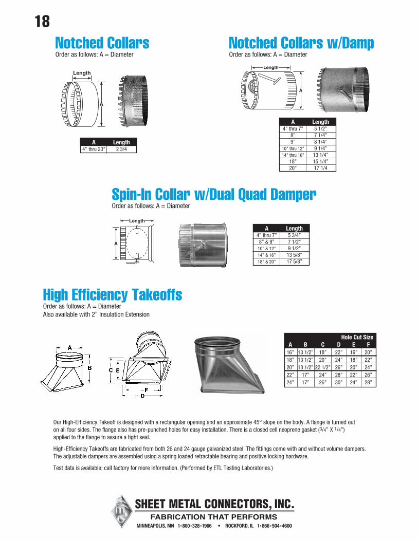
Notched CollarsOrder as follows: A = Diameter
Length
A
Length
A
Our High-Efficiency Takeoff is designed with a rectangular opening and an approximate 45° slope on the body. A flange is turned out on all four sides. The flange also has pre-punched holes for easy installation. There is a closed cell neoprene gasket (3/4” X 1/4”) applied to the flange to assure a tight seal.
High-Efficiency Takeoffs are fabricated from both 26 and 24 gauge galvanized steel. The fittings come with and without volume dampers. The adjustable dampers are assembled using a spring loaded retractable bearing and positive locking hardware.
Test data is available; call factory for more information. (Performed by ETL Testing Laboratories.)
Hole Cut Size A B C D E F 16” 13 1/2” 18” 22” 16” 20” 18” 13 1/2” 20” 24” 18” 22” 20” 13 1/2” 22 1/2” 26” 20” 24” 22” 17” 24” 28” 22” 26” 24” 17” 26” 30” 24” 28”
A Length 4” thru 20” 2 3/4
A Length 4” thru 7” 5 1/2” 8” 7 1/4” 9” 8 1/4” 10” thru 12” 9 1/4” 14” thru 16” 13 1/4” 18” 15 1/4” 20” 17 1/4
Notched Collars w/DampOrder as follows: A = Diameter
High Efficiency TakeoffsOrder as follows: A = DiameterAlso available with 2” Insulation Extension
A Length 4” thru 7” 5 3/4” 8” & 9” 7 1/2” 10” & 12” 9 1/2” 14” & 16” 13 5/8” 18” & 20” 17 5/8”
A
Length
Spin-In Collar w/Dual Quad DamperOrder as follows: A = Diameter
18
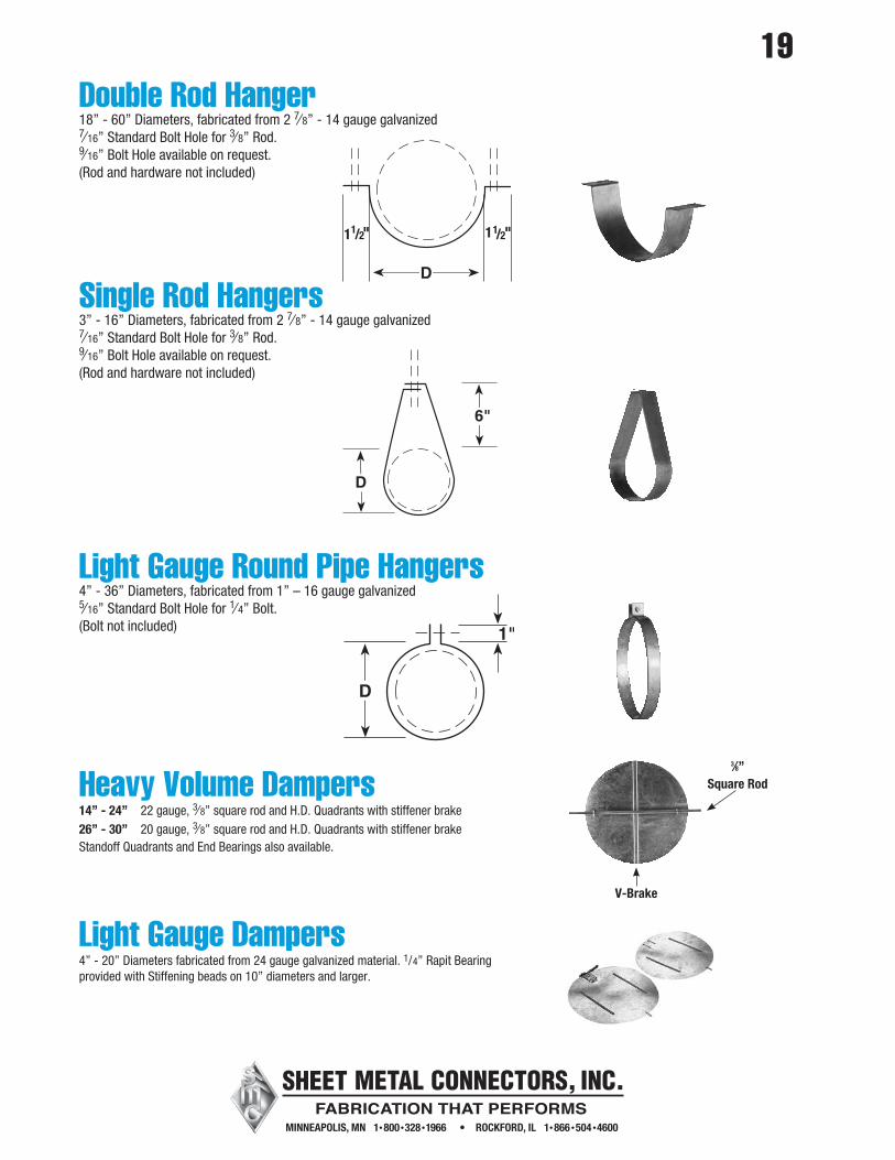
Double Rod Hanger18” - 60” Diameters, fabricated from 2 7⁄ 8” - 14 gauge galvanized7⁄ 16” Standard Bolt Hole for 3⁄ 8” Rod.9⁄ 16” Bolt Hole available on request.(Rod and hardware not included)
Single Rod Hangers3” - 16” Diameters, fabricated from 2 7⁄ 8” - 14 gauge galvanized7⁄ 16” Standard Bolt Hole for 3⁄ 8” Rod.9⁄ 16” Bolt Hole available on request.(Rod and hardware not included)
Light Gauge Round Pipe Hangers4” - 36” Diameters, fabricated from 1” – 16 gauge galvanized5⁄ 16” Standard Bolt Hole for 1⁄ 4” Bolt.(Bolt not included)
Heavy Volume Dampers14” - 24” 22 gauge, 3⁄ 8” square rod and H.D. Quadrants with stiffener brake26” - 30” 20 gauge, 3⁄ 8” square rod and H.D. Quadrants with stiffener brakeStandoff Quadrants and End Bearings also available.
Light Gauge Dampers4” - 20” Diameters fabricated from 24 gauge galvanized material. 1/4” Rapit Bearing provided with Stiffening beads on 10” diameters and larger.
D
6"
D
1"
V-Brake
3⁄8” Square Rod
19

20Wire Rope Hangers
CL18The CL18 Cable Lock is for use with 3/32” or 1/8” wire rope. These size wire ropes are available in 500 foot rolls. Depending upon the wire rope utilized, the CL18 has a working load limit of up to 225 lbs.
Wire Rope 3/32” 25 - 150 lbsWire Rope 1/8” 25-225 lbs
CL23The Maximun Load Range for each size wire rope incorporates a design safety factor of 5.1. The CL23 and wire rope combination should be sized for the job so that the projected load falls within the appropriate working load limit (WLL).
Wire Rope 1/8” 25-225 lbs
KV12 Bracket AssemblyThe KV12 bracket assembly enhances the suspension system by the addition of an integral bracket, which fastens the cable lock to the duck with sheet metal screws. The KV12 Bracket Assembly and CL12 have a working load limit of up to 150 lbs.
Bracket Assembly with CL12 100 per boxFor use with WC3 3/32” Wire Rope
Wire Rope1/8” 500’ Roll3/32” 500’ Roll
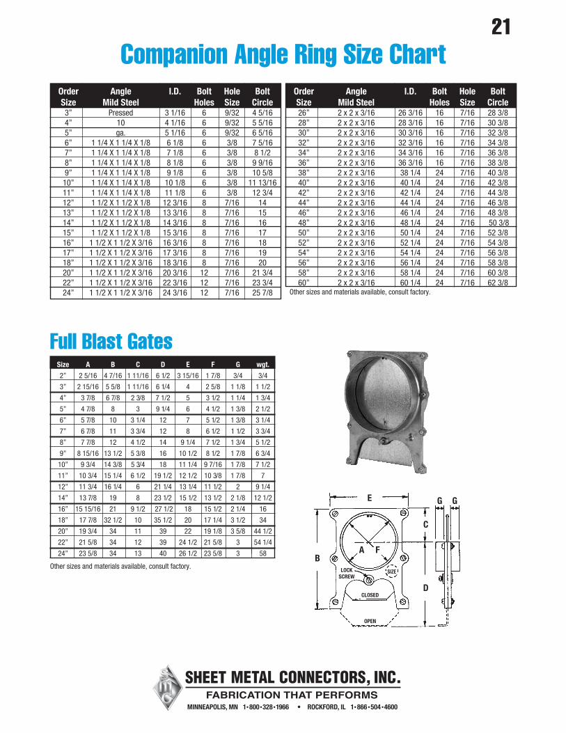
Size A B C D E F G wgt.
2” 2 5/16 4 7/16 1 11/16 6 1/2 3 15/16 1 7/8 3/4 3/4
3” 2 15/16 5 5/8 1 11/16 6 1/4 4 2 5/8 1 1/8 1 1/2
4” 3 7/8 6 7/8 2 3/8 7 1/2 5 3 1/2 1 1/4 1 3/4
5” 4 7/8 8 3 9 1/4 6 4 1/2 1 3/8 2 1/2
6” 5 7/8 10 3 1/4 12 7 5 1/2 1 3/8 3 1/4
7” 6 7/8 11 3 3/4 12 8 6 1/2 1 1/2 3 3/4
8” 7 7/8 12 4 1/2 14 9 1/4 7 1/2 1 3/4 5 1/2
9” 8 15/16 13 1/2 5 3/8 16 10 1/2 8 1/2 1 7/8 6 3/4
10” 9 3/4 14 3/8 5 3/4 18 11 1/4 9 7/16 1 7/8 7 1/2
11” 10 3/4 15 1/4 6 1/2 19 1/2 12 1/2 10 3/8 1 7/8 7
12” 11 3/4 16 1/4 6 21 1/4 13 1/4 11 1/2 2 9 1/4
14” 13 7/8 19 8 23 1/2 15 1/2 13 1/2 2 1/8 12 1/2
16” 15 15/16 21 9 1/2 27 1/2 18 15 1/2 2 1/4 16
18” 17 7/8 32 1/2 10 35 1/2 20 17 1/4 3 1/2 34
20” 19 3/4 34 11 39 22 19 1/8 3 5/8 44 1/2
22” 21 5/8 34 12 39 24 1/2 21 5/8 3 54 1/4
24” 23 5/8 34 13 40 26 1/2 23 5/8 3 58
Full Blast Gates
Other sizes and materials available, consult factory.B
LOCKSCREW
CLOSED
SIZE
OPEN
A F
E
C
G G
D
Order Angle I.D. Bolt Hole Bolt Size Mild Steel Holes Size Circle 3” Pressed 3 1/16 6 9/32 4 5/16 4” 10 4 1/16 6 9/32 5 5/16 5” ga. 5 1/16 6 9/32 6 5/16 6” 1 1/4 X 1 1/4 X 1/8 6 1/8 6 3/8 7 5/16 7” 1 1/4 X 1 1/4 X 1/8 7 1/8 6 3/8 8 1/2 8” 1 1/4 X 1 1/4 X 1/8 8 1/8 6 3/8 9 9/16 9” 1 1/4 X 1 1/4 X 1/8 9 1/8 6 3/8 10 5/8 10” 1 1/4 X 1 1/4 X 1/8 10 1/8 6 3/8 11 13/16 11” 1 1/4 X 1 1/4 X 1/8 11 1/8 6 3/8 12 3/4 12” 1 1/2 X 1 1/2 X 1/8 12 3/16 8 7/16 14 13” 1 1/2 X 1 1/2 X 1/8 13 3/16 8 7/16 15 14” 1 1/2 X 1 1/2 X 1/8 14 3/16 8 7/16 16 15” 1 1/2 X 1 1/2 X 1/8 15 3/16 8 7/16 17 16” 1 1/2 X 1 1/2 X 3/16 16 3/16 8 7/16 18 17” 1 1/2 X 1 1/2 X 3/16 17 3/16 8 7/16 19 18” 1 1/2 X 1 1/2 X 3/16 18 3/16 8 7/16 20 20” 1 1/2 X 1 1/2 X 3/16 20 3/16 12 7/16 21 3/4 22” 1 1/2 X 1 1/2 X 3/16 22 3/16 12 7/16 23 3/4 24” 1 1/2 X 1 1/2 X 3/16 24 3/16 12 7/16 25 7/8
Order Angle I.D. Bolt Hole Bolt Size Mild Steel Holes Size Circle 26” 2 x 2 x 3/16 26 3/16 16 7/16 28 3/8 28” 2 x 2 x 3/16 28 3/16 16 7/16 30 3/8 30” 2 x 2 x 3/16 30 3/16 16 7/16 32 3/8 32” 2 x 2 x 3/16 32 3/16 16 7/16 34 3/8 34” 2 x 2 x 3/16 34 3/16 16 7/16 36 3/8 36” 2 x 2 x 3/16 36 3/16 16 7/16 38 3/8 38” 2 x 2 x 3/16 38 1/4 24 7/16 40 3/8 40” 2 x 2 x 3/16 40 1/4 24 7/16 42 3/8 42” 2 x 2 x 3/16 42 1/4 24 7/16 44 3/8 44” 2 x 2 x 3/16 44 1/4 24 7/16 46 3/8 46” 2 x 2 x 3/16 46 1/4 24 7/16 48 3/8 48” 2 x 2 x 3/16 48 1/4 24 7/16 50 3/8 50” 2 x 2 x 3/16 50 1/4 24 7/16 52 3/8 52” 2 x 2 x 3/16 52 1/4 24 7/16 54 3/8 54” 2 x 2 x 3/16 54 1/4 24 7/16 56 3/8 56” 2 x 2 x 3/16 56 1/4 24 7/16 58 3/8 58” 2 x 2 x 3/16 58 1/4 24 7/16 60 3/8 60” 2 x 2 x 3/16 60 1/4 24 7/16 62 3/8Other sizes and materials available, consult factory.
Companion Angle Ring Size Chart21

Fixed Pattern Diffusers22
• Provides high volume of air delivery
• 360° air diffusion
• Formed steel back panel
• Removable core
• Damper adjusted through diffuser face to
allow proper air balancing
• Heavy gauge steel plenum
• Accepts butterfly damper (3800 Series)
inserted in collar
• Prestige white finish
• Seismic tabs
3 Cone 2 Cone24’ x 24” Lay-In Diffuser
Available in Sizes 6” - 24”
Round Ceiling Diffuser with Butterfly Damper
• Steel Construction
• Step-down diffuser rings
• 360 degree air deflection
• For ceiling application
• Steel Construction
• Removable handle for adjustment
Available in Sizes 6” - 14”

Skyblasts (In Lieu of Raincaps)
Semi-circular flaps (butterfly damper) cover the exhaust stack when fan is off. When the fan is on, flaps are forced out of the way to provide a clear path for air movement. A built-in gutter system is designed to prevent rain and snow from entering stack. Made from galvanized spiral pipe for strength and durability; available in most sizes. Preassembled for immediate installation.*Fabricated from Hammerlock pipe.
ID Pipe OD Pipe Overall Size Length Length Length
12” - 17”* 18” 18” 26 1/2”
18” - 24” 18” 24” 32 1/2”
26” - 32” 20” 28” 36 1/2”
34” - 38” 20” 32” 40 1/2”
40” - 60” 20” 36” 44 1/2”
Floor SweepsFloor sweeps are manufactured from 20 gauge galvanized steel for strength and rigidity.A continuous piano hinge connects the doorto the fitting. Available in 6” standard. Other sizes can be fabricated.
10”12”
2”
5”
81⁄2”
6”
6”
4”
Rectangular DuctworkType-Flat
Round DuctworkType-Round
Access DoorsAccess Doors available in… • Galvanized • Aluminum • Stainless Steel (304 or 316) • PVC CoatedThe doors are also available in 16 ga. black iron when they are to be used for kitchen exhaust systems.
Cellular Sponge GasketA cellular sponge gasket, fixed to the inner plate, keeps the doors free of leaks at pressures tested to 20” w.g.
Access Doors for Round Ductwork10” X 6” – 22 Gauge Doors available to fit on 6” – 16” diameters.16” X 12” – 20 Gauge Doors available to fit on 18” – 36” diameters.
Access Doors for Rectangular Ductwork10” X 6” – 22 Gauge16” X 12” – 20 Gauge
23

24Tek Screws10 x 1/2”10 x 3/4”10 x 1”
1000 or 5000 / Box
Tensioning ToolAdjustable Auto Cut-offHigh Leverage
R4.2 Insulated Flexible Duct4” - 20” Diameter
25’ Per Box
Heavy Duty Flexible Nylon Ties36” Nylon Ties 25 / package48” Nylon Ties 25 / package
Zip Screws8 x 1/2”8 x 3/4”8 x 1”
1000 or 5000 / Box
Duct CapFits Size Range: 6” - 10” 18” - 24”10” - 14” 24’ - 30”14” - 18” 30” - 38”25 Per Box