specifications for works up to j$15m
TRANSCRIPT
NWA Technical Specification, Effective December 17, 2015 Page 1
TECHNICAL SPECIFICATIONS
CONTENTS Page # 0.0 GENERAL 1
1.0 EXCAVATION 4
2.0 GABION WALLS 6
3.0 RUBBLE MASONRY 7
4.0 ROADWORKS 8
5.0 SIDEWALKS, CURBS, AND CURB & GUTTER 14
6.0 CONCRETE 16
7.0 STORMWATER DRAINAGE 24
8.0 STRUCTURAL STEEL WORKS 31
9.0 DRIVING OF STEEL “H” PILE SECTIONS 38
10.0 ENVIRONMENTAL SPECIFICATIONS 45
APPENDIX Test Summary Sheets (sample) Gradation for concrete aggregates Standards for Structures
o Kerb and asphalt detail and access detail o Typical V-drain section o U-drain 1200*1200mm o Random rubble catch basin detail o Cross drain rip section and typical elevation o Manholes kerb inlet with sewer under sidewalk o Guard Rails
53
0.0 GENERAL
0.1 ABBREVIATIONS
(a) “BS” means British Standards (b) “ASTM” means American Society for Testing Materials.
(c) “AASHTO” means American Association of State Highway & Transportation Officials
(d) “MDD” means Maximum Dry Density in accordance with ASTM D1557 Method D
NWA Technical Specification, Effective December 17, 2015 Page 2
0.2 QUALITY CONTROL OF MATERIALS
(a) Quality of Material All materials used in the Works shall be new and of the types and quality specified and shall be approved by the Engineer. Materials shall comply with the requirements, unless modified herein, of the current amended editions, of the American Standards for Testing and Materials, the British Standard Specifications published by the British Standards Institution, or any other recognized Standards that may be quoted. All materials may be checked both at the source and on Site and approval of any material at its source does not necessarily imply that it will be approved on Site. The contractor shall submit evidence of conformance to NWA’s specification in the form of original copies of independent test results. (b) Approval of Source of Supply Before ordering any materials, the Contractor shall submit for the approval of the Engineer, the name of the Supplier and the source of supply, for any materials to be used in the Works. The approval in writing of the Engineer must be obtained before relevant items are obtained. The information concerning the names of Suppliers may be submitted at different times for different materials, as may be convenient, but no source of supply shall be changed without the Engineer’s prior approval. (c) Samples Samples of all materials and workmanship proposed to be employed in the execution of the Works comprised in this Contract may be called for at any time by the Engineer and are to be furnished free by the Contractor. The Engineer will retain until the completion of the Contract samples of the material approved and he shall reject all materials and workmanship not conforming in quality and character with the approved samples. Suitable labelled receptacles for the storage of samples are to be provided by the Contractor without charge.
(d) Additional Tests In addition to the tests required under other Clauses hereof, the Engineer shall have power to order additional independent tests of all materials to be carried out by an approved testing laboratory appointed by him. The costs of this additional testing will be borne by the Contractor. (e) Inspection and Testing Whenever considered necessary by the Engineer, Inspectors may be sent to the Supplier’s premises to test the materials or to supervise their manufacture. Materials shall be tested before leaving the premises as well as after delivery to the Site. The Engineer shall be at liberty to reject materials notwithstanding favourable preliminary test results at the Supplier’s premises. The Contractor shall obtain from the Supplier, test certificates for each batch used showing that the materials have been tested in accordance with the requirements of this Specification relating thereto. Neither the omission of the Engineer to send an Inspector nor the production of the suppliers’ test certificate shall affect the liberty of the Engineer to reject, after delivery, materials found to be unsuitable or not in accordance with this Specification.
NWA Technical Specification, Effective December 17, 2015 Page 3
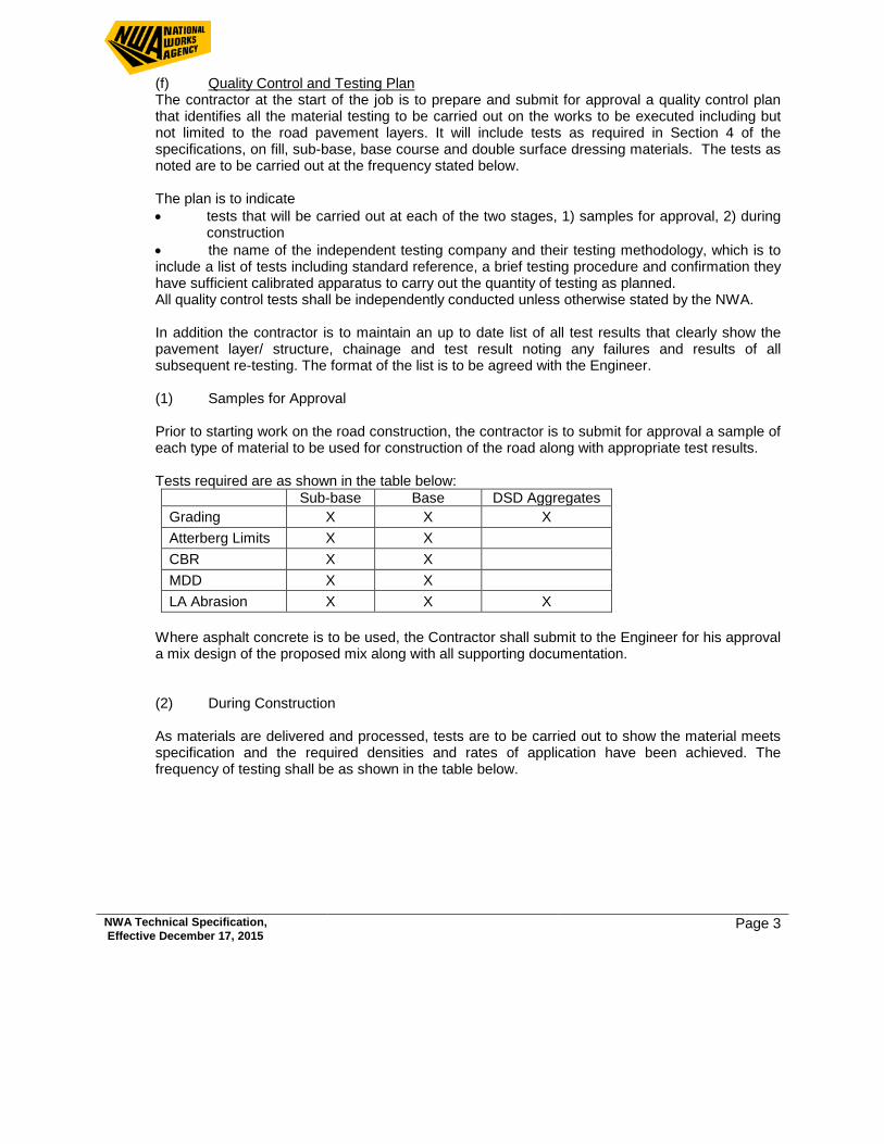
(f) Quality Control and Testing Plan The contractor at the start of the job is to prepare and submit for approval a quality control plan that identifies all the material testing to be carried out on the works to be executed including but not limited to the road pavement layers. It will include tests as required in Section 4 of the specifications, on fill, sub-base, base course and double surface dressing materials. The tests as noted are to be carried out at the frequency stated below.
The plan is to indicate • tests that will be carried out at each of the two stages, 1) samples for approval, 2) during
construction • the name of the independent testing company and their testing methodology, which is to include a list of tests including standard reference, a brief testing procedure and confirmation they have sufficient calibrated apparatus to carry out the quantity of testing as planned. All quality control tests shall be independently conducted unless otherwise stated by the NWA. In addition the contractor is to maintain an up to date list of all test results that clearly show the pavement layer/ structure, chainage and test result noting any failures and results of all subsequent re-testing. The format of the list is to be agreed with the Engineer. (1) Samples for Approval Prior to starting work on the road construction, the contractor is to submit for approval a sample of each type of material to be used for construction of the road along with appropriate test results. Tests required are as shown in the table below:
Sub-base Base DSD Aggregates Grading X X X Atterberg Limits X X CBR X X MDD X X LA Abrasion X X X
Where asphalt concrete is to be used, the Contractor shall submit to the Engineer for his approval a mix design of the proposed mix along with all supporting documentation.
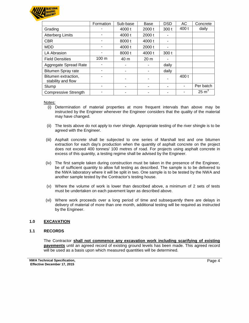
(2) During Construction As materials are delivered and processed, tests are to be carried out to show the material meets specification and the required densities and rates of application have been achieved. The frequency of testing shall be as shown in the table below.
NWA Technical Specification, Effective December 17, 2015 Page 4
Formation Sub-base Base DSD AC Concrete Grading - 4000 t 2000 t 300 t 400 t daily Atterberg Limits - 4000 t 2000 t - CBR - 8000 t 4000 t - MDD - 4000 t 2000 t - LA Abrasion - 8000 t 4000 t 300 t Field Densities 100 m 40 m 20 m - Aggregate Spread Rate - - - daily Bitumen Spray rate - - - daily Bitumen extraction, stability and flow
- - - - 400 t
Slump - - - - - Per batch Compressive Strength - - - - - 25 m3
Notes:
(i) Determination of material properties at more frequent intervals than above may be instructed by the Engineer whenever the Engineer considers that the quality of the material may have changed.
(ii) The tests above do not apply to river shingle. Appropriate testing of the river shingle is to be
agreed with the Engineer.
(iii) Asphalt concrete shall be subjected to one series of Marshall test and one bitumen extraction for each day’s production when the quantity of asphalt concrete on the project does not exceed 400 tonnes/ 100 metres of road. For projects using asphalt concrete in excess of this quantity, a testing regime shall be advised by the Engineer.
(iv) The first sample taken during construction must be taken in the presence of the Engineer,
be of sufficient quantity to allow full testing as described. The sample is to be delivered to the NWA laboratory where it will be split in two. One sample is to be tested by the NWA and another sample tested by the Contractor’s testing house.
(v) Where the volume of work is lower than described above, a minimum of 2 sets of tests
must be undertaken on each pavement layer as described above.
(vi) Where work proceeds over a long period of time and subsequently there are delays in delivery of material of more than one month, additional testing will be required as instructed by the Engineer.
1.0 EXCAVATION 1.1 RECORDS The Contractor shall not commence any excavation work including scarifying of existing
pavements until an agreed record of existing ground levels has been made. This agreed record will be used as a basis upon which measured quantities will be determined.
NWA Technical Specification, Effective December 17, 2015 Page 5
The Contractor’s unit rates entered in the Bill of Quantities for excavation shall include for excavating in any type of ground and for grubbing up roots. boulders or other obstructions not exceeding one cubic metre (1 m3).
1.2 ROCK The extra over item provided for excavating in rock shall be allowed only where in the opinion of
the Engineer it is necessary to use compressors with pneumatic hammers, explosives or sledges to remove the material. The Contractor shall obtain the Engineer’s instruction removing any rock.
Materials which can be removed by the use of a mechanical digger or similar shall not be considered as rock.
1.3 BLASTING Where excavations are to be carried out by blasting the written authority of the Engineer shall be
obtained before such operations are begun. The Contractor shall be held responsible that the charges are not excessive, that charged boreholes are properly protected before being fired and that proper precautions are taken for the safety of persons and property.
1.4 SETTING OUT Excavation shall be carried out to the correct lines, levels and falls as required, thoroughly
consolidated, and all soft spots, cut outs or excessive excavation filled with concrete or other material as may be directed.
The Contractor shall record on a drawing the depth of every excavation, showing the nature of
earth or stone which drawing, when complete, shall be submitted to the Engineer. All excavations are measured net and allowance should be made in the rates for the extra digging
required for timbering, working space, cofferdams or other temporary works, and for the increase in bulk when disposing of excavated materials.
Planking and strutting, shoring etc., shall be designed, supplied, fixed and removed by the
Contractor and shall be of sufficient strength to resist earth and water pressure and to ensure the safety of workmen and the works and to prevent damage to any adjoining property. Temporary works designs shall be submitted to the Engineer for his approval before the works are carried out.
1.5 RATES The rates for excavation shall include for timbering and temporary shuttering but the extent to
which it is found necessary to erect same is solely at the discretion of the Contractor and any collapse of the sides of excavations or other damage to persons and property due to the omission of the planking and strutting shall be made good at the Contractor’s own expense.
The rates for excavation shall include for all trimming and for levelling and ramming bottoms of
excavations to receive concrete.
NWA Technical Specification, Effective December 17, 2015 Page 6
The rates for excavation shall include for keeping the excavations free from water by pumping, bailing or otherwise.
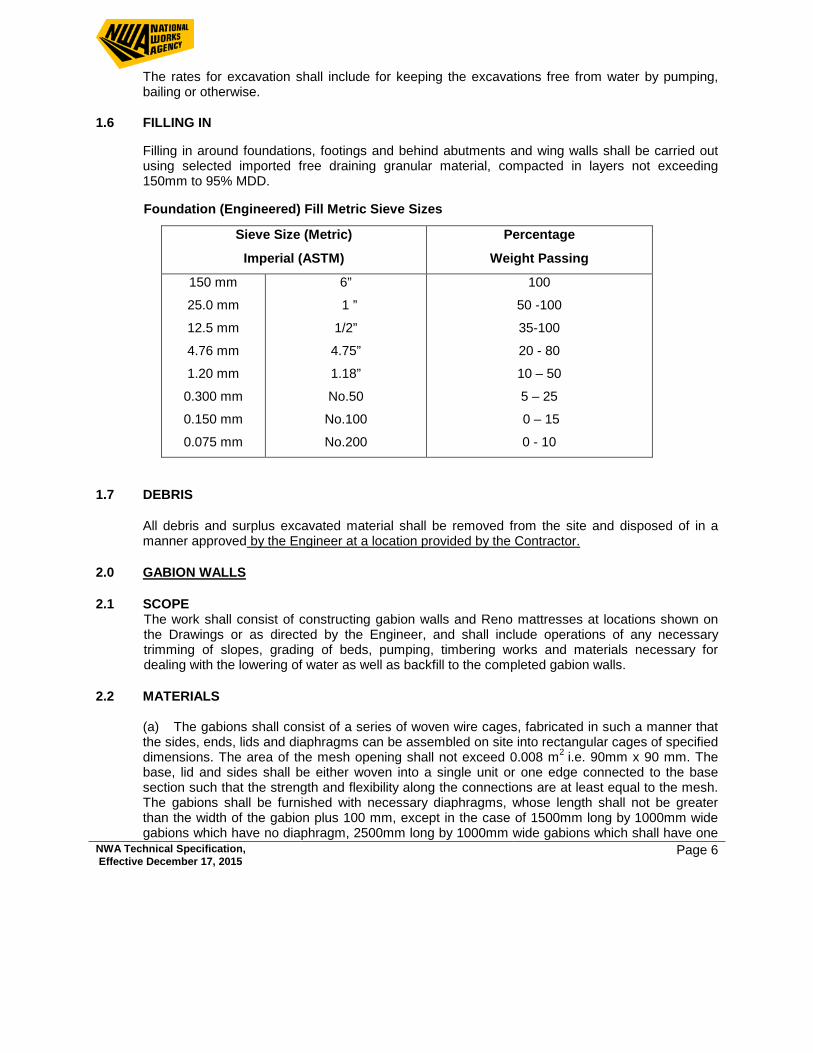
1.6 FILLING IN Filling in around foundations, footings and behind abutments and wing walls shall be carried out
using selected imported free draining granular material, compacted in layers not exceeding 150mm to 95% MDD.
Foundation (Engineered) Fill Metric Sieve Sizes
1.7 DEBRIS
All debris and surplus excavated material shall be removed from the site and disposed of in a manner approved by the Engineer at a location provided by the Contractor.
2.0 GABION WALLS 2.1 SCOPE
The work shall consist of constructing gabion walls and Reno mattresses at locations shown on the Drawings or as directed by the Engineer, and shall include operations of any necessary trimming of slopes, grading of beds, pumping, timbering works and materials necessary for dealing with the lowering of water as well as backfill to the completed gabion walls.
2.2 MATERIALS
(a) The gabions shall consist of a series of woven wire cages, fabricated in such a manner that the sides, ends, lids and diaphragms can be assembled on site into rectangular cages of specified dimensions. The area of the mesh opening shall not exceed 0.008 m2 i.e. 90mm x 90 mm. The base, lid and sides shall be either woven into a single unit or one edge connected to the base section such that the strength and flexibility along the connections are at least equal to the mesh. The gabions shall be furnished with necessary diaphragms, whose length shall not be greater than the width of the gabion plus 100 mm, except in the case of 1500mm long by 1000mm wide gabions which have no diaphragm, 2500mm long by 1000mm wide gabions which shall have one
Sieve Size (Metric)
Imperial (ASTM)
Percentage
Weight Passing
150 mm
25.0 mm
12.5 mm
4.76 mm
1.20 mm
0.300 mm
0.150 mm
0.075 mm
6”
1 ”
1/2”
4.75”
1.18”
No.50
No.100
No.200
100
50 -100
35-100
20 - 80
10 – 50
5 – 25
0 – 15
0 - 10
NWA Technical Specification, Effective December 17, 2015 Page 7
central diaphragm, and Reno mattresses where the diaphragms shall have a maximum spacing of 600 mm, properly secured on the base such that no further tying will be necessary.
(b) The wire shall be satisfactorily protected to ensure durability in corrosive conditions.
Minimum sizes shall be Gauge 5 for the frames, Gauge 8 for the hexagonal weaving and Gauge 12 for the tie wires. The tensile strength of the wire shall be at least 420 kN/m2 (60,000 PSI)
(c) The rock for filling the gabions shall be sound and durable, and shall range in size from
150mm to 225mm maximum dimension, they shall be as regular in shape as possible, with a least dimension not less than 50% of its maximum.
(d) Sand, gravel or soil shall not be used for filling the gabion baskets. 2.3 METHOD OF CONSTRUCTION (a) The bed on which the gabion wall is to be placed shall be cleared of large stones so that the
baskets will rest on an even foundation prior to being filled and compacted to the satisfaction of the Engineer. Cuts shall be dug to anchor the ends of the walls.
(b) Each gabion unit shall be assembled by binding all vertical edges at approximately 150 mm
spacing or by continuous stitch around the vertical edges. (c) Prior to filling, a full row of baskets shall be placed in position, and set to line and grade, and
tied together. The baskets must be placed in tension to achieve their proper alignment and to ensure that they are properly stone packed. Tension shall he applied by attaching wire to the baskets, drawing tight, and anchoring the wires. The tension wires shall be removed once the baskets are filled. The facing rocks shall be placed by hand, leaving as few voids as possible.
(d) When the basket is about one-third full, all sides shall be secured with cross connecting wire,
and again when two-thirds full. Baskets shall be filled flush; they shall not be over-filled. 2.4 BASIS OF PAYMENT The amounts measured for payment shall be the number of cubic metres constructed and
accepted, in keeping with dimensions shown on the drawings or ordered in writing by the Engineer. Payment will be at the unit rate in the B.Q. and shall include compensation for all material, equipment, tools and labour to excavate and construct the wall in keeping with the specifications.
3.0 RUBBLE MASONRY 3.1 SCOPE The works shall consist of constructing rubble masonry walls at locations and to the lines, grades,
dimensions and details shown on the drawings or as directed by the Engineer all in conformity with the requirements of this specification and other contract documents.
NWA Technical Specification, Effective December 17, 2015 Page 8
3.2 MATERIALS Concrete for this work shall conform to the requirements as set forth in Section 6, Concrete. The
stones for the masonry shall be clean, hard and durable. They shall be free from dirt, oil or other deleterious materials and from seams and cracks and shall be well proportioned, roughly rectangular and have dimensions of not less than 125mm.
3.3 CONSTRUCTION METHODS Excavation for walls associated with storm drainage facilities shall be in accordance with the
Trench Excavation of the Specifications. The sizes of stones on exposed faces shall vary and the stones shall be set or hammer dressed
so that variations from the true line do not vary by more than 20mm. The masonry shall be finished on the exposed face by raking out the joints for a depth of not less than 12.5mm and pointing so as to leave a raised pointing on the face 30mm wide and 6mm high.
The masonry shall be kept wet while pointing and in hot or dry weather the pointing shall be
protected from the sun and kept wet for at least three days after completion. The rubble masonry shall be founded on concrete as called for on the drawings and shall have
weep-holes formed at 3m intervals or as shown on the drawings. Belt beams shall be constructed in mass concrete as shown in the standard details or instructed by the Engineer. The capping or masonry shall be carried out in lengths not exceeding 3m or as shown on the drawings.
Porous granular backfill as described elsewhere in the specifications shall be brought up to within
150mm from the top of the wall to allow for drainage. 4.0 ROADWORKS 4.1 SCOPE
This work shall consist of preparing the sub-grade for the road, furnishing, placing and compacting a base course and placing a wearing surface. All work to be at locations and to the lines, grades and cross sections shown on the Drawings or as directed by the Engineer, all to conform with the requirements of the Specifications and the Contract Documents.
4.2 FORMATION LEVEL
Formation level shall be the surface level of the ground obtained after completion of the earthworks, that is the underside of the sub-base or where no sub-base is specified, the underside of the base. Any excess depth excavated below formation level, tolerance see below, shall be back-filled with material acceptable for road construction and compacted to 95% MDD.
4.3 EXCAVATING & FILLING
a) The Contractor shall carry out such scarifying, excavating or filling as may be necessary to form the new sub-grade in accordance with the Drawings and shall adhere to the slopes, levels, depths and heights shown thereon. Unless otherwise directed by the Engineer, all suitable excavated materials shall be used where filling material is required. The Contractor shall remove any excavated material that in the opinion of the Engineer is unsuitable for filling, from the site.
NWA Technical Specification, Effective December 17, 2015 Page 9
Material used as fill shall be deposited and compacted to 95% MDD in layers not exceeding 150mm in depth after final compaction. Each layer shall extend over the full width of the formation. Where materials of widely different characteristics are drawn from different sources such material shall be deposited in alternate layers over the full width of the formation. No muds, organic material, silt, soft or otherwise unsuitable material shall be used as fill. (b) During preparation of the sub-grade the Contractor shall control and direct constructional traffic uniformly over its full width. Fill material shall not be stock piled on the sub-grade unless permitted by the Engineer. (c) Should the quantity of excavation from the works be insufficient for the amount of filling required, the deficiency shall be made good by approved, imported suitable material and the Contractor shall be responsible for locating and obtaining and testing such material.
4.4 PREPARATION OF SUB-GRADE
(a) All fill material used in earthworks shall be compacted to the requirements of these Specifications, by equipment approved by the Engineer for that purpose. Unless otherwise approved the fill material shall be compacted at its optimum moisture content by a minimum of 6 passes of a heavy (minimum 8 tonnes) smooth-wheeled roller. At formation level the sub-grade material shall be compacted to give a minimum California Bearing Ratio (CBR) of 30%. The surface of the formation shall be finished smooth and true to the levels and cross-sections shown on the plans and shall not vary more than 12mm in 3.0m in profile and cross section or more than 12mm from design elevation. (b) Where existing levels are higher than formation levels it shall be excavated and removed in such a way that the formation undergoes the minimum amount of disturbance. When formation level is reached, the sub-grade material shall be compacted as specified to a minimum of 95% MDD and reshaped to meet the required levels and grades.
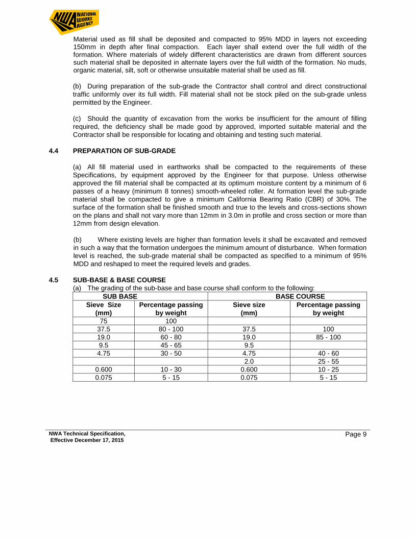
4.5 SUB-BASE & BASE COURSE
(a) The grading of the sub-base and base course shall conform to the following: SUB BASE BASE COURSE
Sieve Size (mm)
Percentage passing by weight
Sieve size (mm)
Percentage passing by weight
75 100 37.5 80 - 100 37.5 100 19.0 60 - 80 19.0 85 - 100 9.5 45 - 65 9.5 4.75 30 - 50 4.75 40 - 60
2.0 25 - 55 0.600 10 - 30 0.600 10 - 25 0.075 5 - 15 0.075 5 - 15
NWA Technical Specification, Effective December 17, 2015 Page 10
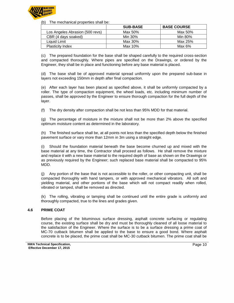
(b) The mechanical properties shall be: SUB-BASE BASE COURSE Los Angeles Abrasion (500 revs) Max 50% Max 50% CBR (4 days soaked) Min 30% Min 80% Liquid Limit Max 30% Max 25% Plasticity Index Max 10% Max 6%
(c) The prepared foundation for the base shall be shaped carefully to the required cross-section and compacted thoroughly. Where pipes are specified on the Drawings, or ordered by the Engineer, they shall be in place and functioning before any base material is placed.
(d) The base shall be of approved material spread uniformly upon the prepared sub-base in layers not exceeding 150mm in depth after final compaction.
(e) After each layer has been placed as specified above, it shall be uniformly compacted by a roller. The type of compaction equipment, the wheel loads, etc. including minimum number of passes, shall be approved by the Engineer to ensure thorough compaction for the full depth of the layer.
(f) The dry density after compaction shall be not less than 95% MDD for that material.
(g) The percentage of moisture in the mixture shall not be more than 2% above the specified optimum moisture content as determined in the laboratory. (h) The finished surface shall be, at all points not less than the specified depth below the finished pavement surface or vary more than 12mm in 3m using a straight edge.
(i) Should the foundation material beneath the base become churned up and mixed with the base material at any time, the Contractor shall proceed as follows. He shall remove the mixture and replace it with a new base material to the required depth of base as shown on the Drawings or as previously required by the Engineer; such replaced base material shall be compacted to 95% MDD. (j) Any portion of the base that is not accessible to the roller, or other compacting unit, shall be compacted thoroughly with hand tampers, or with approved mechanical vibrators. All soft and yielding material, and other portions of the base which will not compact readily when rolled, vibrated or tamped, shall be removed as directed. (k) The rolling, vibrating or tamping shall be continued until the entire grade is uniformly and thoroughly compacted, true to the lines and grades given.
4.6 PRIME COAT
Before placing of the bituminous surface dressing, asphalt concrete surfacing or regulating course, the existing surface shall be dry and must be thoroughly cleaned of all loose material to the satisfaction of the Engineer. Where the surface is to be a surface dressing a prime coat of MC-70 cutback bitumen shall be applied to the base to ensure a good bond. Where asphalt concrete is to be placed, the prime coat shall be MC-30 cutback bitumen. The prime coat shall be
NWA Technical Specification, Effective December 17, 2015 Page 11
uniformly applied by means of a pressure distributor at a rate between 0.9 and 1.2 litres per square metre.
After application of the prime coat, it shall be cured for a minimum of 48 hours. Traffic shall not be allowed on the primed surface during the curing period. The curing period shall be until the bituminous material has penetrated and dried, and in the opinion of the Engineer, shall not be picked up by traffic. Where traffic cannot be withheld from the primed surface before setting, the prime coat shall be blinded with a light uniform sprinkling of sand. The primed surface shall not be left exposed for longer than 7 days.
4.7 SINGLE & DOUBLE SURFACE DRESSING
(a) Single surface dressings shall consist of a single application of either 85/100 bitumen or CRS-2 bitumen emulsion sprayed on a prepared surface followed with a single application of stone chippings. The nominal size and spread rate of the stone chippings and the type and nominal spray rate of the bituminous binder are stated in the Bills of Quantities. The actual rates to be applied shall be determined from field trials conducted on test sections as approved by the Engineer. (b) Double surface dressing shall consist of a first coat of 85/100 bitumen conforming to AASHTO M-20 or CRS-2 bitumen emulsion conforming to ASTM D 2397 sprayed at a rate of 1.1 – 1.3 litres/m2 topped with a layer of 19mm nominal aggregate at 24 kg/m2 followed by a second coat of 85/100 bitumen or CRS-2 emulsion at a rate of 0.9 – 1.1 litres/m2 topped with a layer of 9mm nominal aggregate at 12 kg/m2 including compaction with one or more pneumatic tyred rollers or by approved steel wheel roller until the aggregate is firmly embedded in the asphaltic material, all as specified. The actual rates to be applied shall be determined from field trials conducted on test sections but the Engineer may order subsequent test sections or alter the previously established rates of application where he deems it necessary.
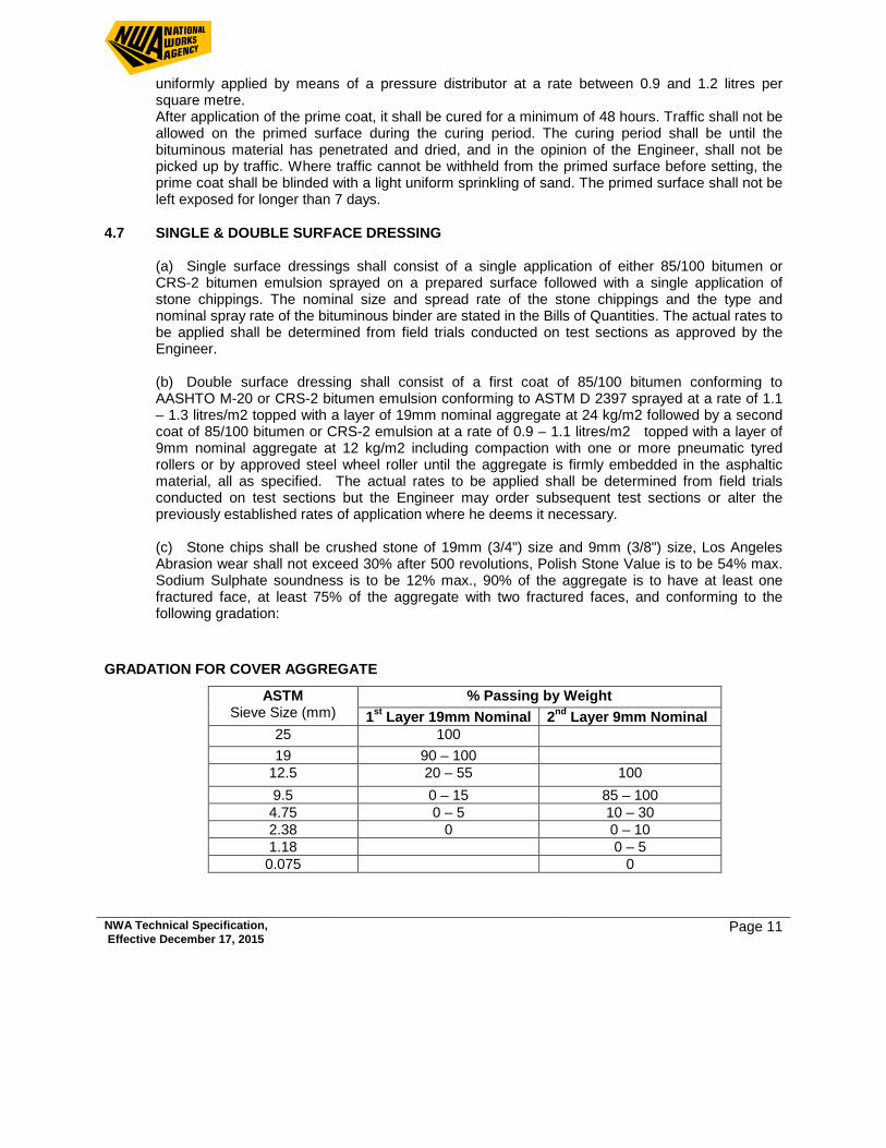
(c) Stone chips shall be crushed stone of 19mm (3/4") size and 9mm (3/8") size, Los Angeles
Abrasion wear shall not exceed 30% after 500 revolutions, Polish Stone Value is to be 54% max. Sodium Sulphate soundness is to be 12% max., 90% of the aggregate is to have at least one fractured face, at least 75% of the aggregate with two fractured faces, and conforming to the following gradation:
GRADATION FOR COVER AGGREGATE
ASTM Sieve Size (mm)
% Passing by Weight 1st Layer 19mm Nominal 2nd Layer 9mm Nominal
25 100 19 90 – 100
12.5 20 – 55 100 9.5 0 – 15 85 – 100 4.75 0 – 5 10 – 30 2.38 0 0 – 10 1.18 0 – 5 0.075 0
NWA Technical Specification, Effective December 17, 2015 Page 12
SPREAD RATE FOR COVER AGGREGATE Kg/m2
1st Layer 19mm Nominal 20 – 24
2nd Layer 9mm Nominal 10 – 12 4.8 ASPHALT CONCRETE
(a) Bituminous mixes shall be prepared in an approved plant where heated aggregate and bitumen shall be measured separately and accurately by weight or volume.
(b) The aggregates used in asphalt concrete sourced from the approved pre-mix plant shall be
durable, clean, fractured face, free from deleterious matter, etc., and shall have the following properties:
1. Flakiness Index < 30.0% 2. L.A. abrasion (500 revs) < 35.5% 3. soundness (sodium sulphate) < 12.0% 4. water absorption < 2.0% 5. plastic fines in blended aggregate < 4.0% 6. polish stone value (wearing course) > 54.0
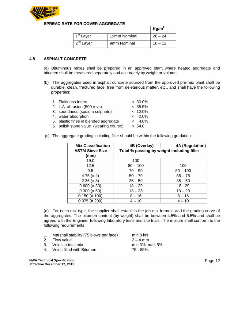
(c) The aggregate grading including filler should be within the following gradation:
Mix Classification 4B (Overlay) 4A (Regulation) ASTM Sieve Size
(mm) Total % passing by weight including filler
19.0 100 12.5 80 – 100 100 9.5 70 – 90 80 – 100
4.75 (# 4) 50 – 70 55 – 75 2.36 (# 8) 35 – 50 35 – 50
0.600 (# 30) 18 – 29 18 - 29 0.300 (# 50) 13 – 23 13 – 23 0.150 (# 100) 8 – 16 8 – 16 0.075 (# 200) 4 – 10 4 – 10
(d) For each mix type, the supplier shall establish the job mix formula and the grading curve of the aggregates. The bitumen content (by weight) shall be between 4.5% and 6.5% and shall be agreed with the Engineer following laboratory tests and site trials. The mixture shall conform to the following requirements 1. Marshall stability (75 blows per face) min 8 kN 2. Flow value 2 – 4 mm 3. Voids in total mix. min 3%, max 5%. 4. Voids filled with Bitumen 75 - 85%.
NWA Technical Specification, Effective December 17, 2015 Page 13
The contractor shall produce test results showing bitumen content and compliance with the above requirements to the satisfaction of the Engineer.
(e) The contractor shall lay and compact the mix by methods approved by the Engineer.
(f) The temperature of the asphalt concrete immediately prior to the beginning of compaction
shall not be less than 1200C. Compaction must be completed before the temperature of the asphalt concrete drops below 1000C.
(g) The percent Marshall Compaction for the asphalt concrete shall satisfied the minimum
requirement of 95% of laboratory Marshall Bulk density. 4.9 TYPE 2 MIX – MATERIALS FOR ASPHALT CONCRETE
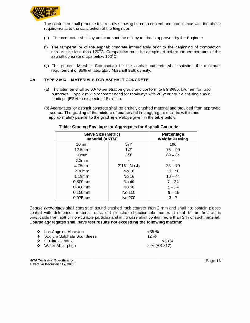
(a) The bitumen shall be 60/70 penetration grade and conform to BS 3690, bitumen for road purposes. Type 2 mix is recommended for roadways with 20-year equivalent single axle loadings (ESALs) exceeding 18 million.
(b) Aggregates for asphalt concrete shall be entirely crushed material and provided from approved
source. The grading of the mixture of coarse and fine aggregate shall be within and approximately parallel to the grading envelope given in the table below:
Table: Grading Envelope for Aggregates for Asphalt Concrete
Sieve Size (Metric) Imperial (ASTM)
Percentage Weight Passing
20mm 12.5mm 10mm 6.3mm 4.75mm 2.36mm 1.19mm 0.600mm 0.300mm 0.150mm 0.075mm
3\4” 1\2” 3/8”
- 3\16” (No.4)
No.10 No.16 No.40 No.50 No.100 No.200
100 75 – 90 60 – 84
- 33 – 70 19 - 56 10 – 44 7 – 34 5 – 24 9 – 16 3 - 7
Coarse aggregates shall consist of sound crushed rock coarser than 2 mm and shall not contain pieces coated with deleterious material, dust, dirt or other objectionable matter. It shall be as free as is practicable from soft or non-durable particles and in no case shall contain more than 2 % of such material. Coarse aggregates shall have test results not exceeding the following maxima:
Los Angeles Abrasion <35 % Sodium Sulphate Soundness 12 % Flakiness Index <30 % Water Absorption 2 % (BS 812)
NWA Technical Specification, Effective December 17, 2015 Page 14
The bitumen affinity of the stone shall be good and the bitumen retention shall be at least 75 % when tested for stripping. If there is less than 75 % of bitumen retention, the aggregates shall be rejected, or an approved method of treating shall be used to change the material from a hydrophilic to a hydrophobic state.
Fine aggregates shall consist of crushed rock material finer than 2 mm and coarser than 0.09mm and shall be free from clay, silt, organic and other deleterious matter and shall be non- plastic.
Fine aggregates shall have test results not exceeding the following maxima: Los Angeles Abrasion 40 % Sodium Sulphate Soundness 12 %
Mineral filler shall consist of material finer than 0.09 mm and ordinary Portland cement or finely ground particles of lime stone shall be used. At least 75% (by weight) shall pass a 0.075 mm sieve and 100% shall pass a 0.425 mm sieve. Mineral filler shall have a bulk density in toluene measured in accordance with BS 812 of between 0.5 and 0.9 kg per litre. Requirements for Asphalt Concrete The bitumen/binder content (by weight) shall be between four (4) and six (6) percent and shall be agreed with the Engineer following laboratory tests and site trials. The mixture of the asphalt concrete shall comply with the following requirements:
Marshal Stability (75 blows per face) min.10,000N Flow Value 2-4 mm Voids in total Mix min. 3 %, max. 5 %. Voids filled with Bitumen 65-75%
5.0 SIDEWALKS, KERB, KERB & CHANNEL
5.1 SCOPE This work shall consist of constructing sidewalks, kerbs, and kerb and channel, all to conform to
the requirements of the Drawings, the Specifications and the Contract Documents. 5.2 MATERIALS (a) Base course material shall conform to the requirements of Section 4.5
(b) Concrete shall have a cube crushing strength of 20 MPa at 28 days as per BS 1881. 5.3 PREPARATION OF FORMATION The formation is to be prepared in accordance with the requirements Clause 4.2 of the
Specification. It shall be free of all loose material, uniformly graded and rolled. 5.4 BASE The base is to be prepared in accordance with the requirements of the detail drawings and Clause
4.5 of these Specifications. The base shall be shaped to the true lines and grades as shown on the Drawings or as directed by the Engineer. Compaction shall be to 95% MDD.
NWA Technical Specification, Effective December 17, 2015 Page 15
5.5 CONCRETE SIDEWALKS Sidewalks shall be constructed as shown on the drawings and shall consist of base course placed and
compacted to 95% MDD to the required thickness and slope to give a finished surface 100 mm below the final levels of the sidewalk. A 100 mm thick 20 MPa in-situ concrete slab shall then be laid upon the prepared base. The concrete shall have a "broomed" finish and shall be marked transversely and longitudinally at 1m intervals or as directed by the Engineer. Prior to any concrete sidewalk being constructed the Contractor shall construct a test strip or strips which when approved will form the basis for the acceptance or rejection of the surface finish.
5.6 PRECAST CONCRETE KERBS & KERB & CHANNEL (a) Prior to any precast kerb being laid the Contractor shall submit samples as required by the
Engineer for Approval. The samples shall meet the Engineers requirements in terms of surface finish and texture and when cored shall be in accordance with the Concrete Specifications. (b) Excavation shall be made to the required depth and the base upon which the kerbing is to be set shall be compacted to a firm, even surface.
(c) Precast concrete kerbs, 20 MPa concrete, shall conform to the requirements of BS 340 and shall be of the shape and size detailed on the drawings. The length shall be 1.0m except where small radii dictate shorter lengths. They shall be laid and bedded in a 12mm layer of mortar on a 150mm deep foundation of 20 MPa concrete constructed as shown on the drawings. Specially cast kerbs or insitu concrete kerbs shall be used in curves where the radius is 12m or less. Where insitu concrete kerbs are used or a kerb machine is used to lay kerb, a saw-cut joint shall be made every 3.0m horizontally. Broken or damaged or honeycombed kerbs shall not be used and must be removed off site. Joints shall be 12mm +/-3mm and mortared. All mortar used must meet the requirements of the Concrete Specifications.
(d) All kerbs and quadrants shall be laid true to line including radius, and level and any unit found
to be more than 3mm out of line or level at either end shall be lifted and re-laid. Unless otherwise specified they shall be 150mm +/- 5mm above the asphalt at the edge of the road.
(e) After the concrete has set sufficiently, the backfilling behind the kerbs shall be completed to the lines shown on the Drawings, or as ordered, by refilling to the required elevation with approved material which shall be placed in layers of not over 150mm in depth, and compacted until firm and solid.
(f) Channels shall be built to the grades and dimensions shown on the drawings and shall be integral with the kerb base. The invert of the gutter shall be steel float finished and the complete operation shall be carried out before the concrete is set.
(f) All kerbs and channels shall be laid before the base course in the respective areas can be
finished.
5.7 PAYMENT
(a) Payment for the base for walkways and sidewalks shall be per square metre (m2). The price includes excavation to subgrade, supply of approved base material, grading, compaction to 95% MDD, disposal of surplus or unsuitable material and testing of materials. No payment will be made until test results on the base material, and compaction tests have been submitted to the Engineer showing compliance with the Specifications.
NWA Technical Specification, Effective December 17, 2015 Page 16
(b) Payment for kerbs and kerb and gutter shall be per linear metre. The price shall include excavation and disposal of surplus material, formwork, grading to receive base, concrete, supply of and laying curved and straight kerb, jointing, saw-cutting etc. (c) No payment will be made until concrete test results have been obtained for the kerbs laid including the in-situ concrete base. Payment for kerbs and channels having a compressive strength of greater than 15 MPa but less than specified will be paid for at 75% of the bid rate. There will be no payment for kerbs or channels having a compressive strength of less than 15 MPa. Kerb not laid to line, grade and radius, and broken kerb when used anywhere on the works shall be replaced at the Contractor’s cost. (d) Payment for concrete sidewalk shall be per square metre laid. The price is to include excavation and disposal of surplus material, formwork, grading and compaction of subgrade, 100mm of approved base compacted to 95% MDD, supply and placing of concrete, surface finishes and tooling and curing of the concrete. The rate is to allow for forming ramps at intersections and construction of curves. (e) No payment will be made until laboratory test results have been submitted for the concrete sidewalk and the surface finish is acceptable to the Engineer. Payment for sidewalks having a concrete compressive strength of greater than 15 MPa but less than specified will be paid for at 75% of the bid rate. There will be no payment for sidewalks having a concrete compressive strength of less than 15 MPa.
6.0 CONCRETE 6.1 SCOPE The work shall include the mixing (in an approved offsite batching plant or on site) and placing of
concrete at the location and to the dimensions shown on the plans. Concrete shall comprise of Portland cement, water, fine aggregate and coarse aggregate and shall be proportioned, mixed and placed in accordance with these specifications.
6.2 USE OF READY MIXED CONCRETE Where the Contractor proposes using ready mixed concrete, he shall submit full details of
proposed arrangements to the Engineer in writing before any concrete will be accepted on site. This specifically includes the proposed mix design and the 28-day crushing test results of the lab / plant mix.
All ready mixed concrete delivered to the site shall comply with ASTM C 94-81, C 143-78 along
with 0231-82 or C 173-78 and C 873-80 or C 39-81. 6.3 CEMENT (a) All cement used in the works shall be ordinary Portland cement complying with BS 12 or
AASHTO M 85. (b) Each consignment of cement delivered to the site shall be kept separate and distinct. All
accepted cement stored on site shall be kept in a suitable shed, which shall be weather tight and well ventilated. The cement shall be effectively protected from the weather during transport and until used in the works.
NWA Technical Specification, Effective December 17, 2015 Page 17
(c) If the Engineer approves the handling of cement in bulk it shall be stored in approved silos which shall be water-tight free from condensation and other defects likely to cause air-setting or other deterioration of the material. Cement more than three months old shall not be used.
6.4 REJECTION OF UNSUITABLE CEMENT The Engineer will reject any cement, which does not comply with the appropriate standard. He will
also reject cement, which has deteriorated due to inadequate protection or other sources. The Contractor shall remove all rejected cement from the site without delay at his own expense.
6.5 FINE AGGREGATES Fine Aggregate shall consist of clean, course and hard sand, free from dust and organic
impurities, obtained from an approved source and shall comply with the requirements for fine aggregate of BS 882. The sand shall be well graded and must pass a 18mm sieve and not more than 10% must pass a No. 100 BS sieve. It shall be washed without extra cost if so directed by the Engineer.
6.6 COARSE AGGREGATE
(a) Coarse aggregate shall be clean uncrushed gravel, crushed gravel, screened pit ballast or crushed stone free from clay, earth or other impurities and is to be obtained from a source approved by the Engineer (b) The coarse aggregates shall comprise naturally occurring material complying with the requirements of Table 1 of BS 882. (“Coarse Aggregates From Natural Sources”) (c) Coarse aggregate shall be graded to pass a 19 mm sieve and be retained on a 9.5 mm sieve. The coarse aggregate unless, otherwise authorised by the Engineer shall be delivered to the site in separate sizes.
6.7 TESTING OF AGGREGATES
(a) The flakiness index for all coarse aggregates to be used for concreting, when determined by the sieve method described in BS 812 shall not exceed 40% for 62.5mm into 37.5mm aggregate nor shall it exceed 35% for 18mm and 10mm aggregate. The grading specification for aggregates for concrete shall comply with BS 882. (Appendix A).
(b) Prior to any aggregate being used in concrete on or for the works, approval for their use shall be sought from the Engineer. Such requests shall be accompanied by test results. During the course of the project, each load delivered to the site shall he accompanied by a delivery note, to be retained if so required by the Engineer stating the quantity and description of the aggregates delivered.
6.8 STORAGE AND DELIVERY OF AGGREGATE
(a) The coarse aggregate unless otherwise authorised by the Engineer shall be delivered to the site in separate sizes. In case of aggregates passing a 5mm sieve, they shall have been deposited on site of mixing for not less than 16 hours before use.
NWA Technical Specification, Effective December 17, 2015 Page 18
(b) All aggregates brought upon the site shall be kept free from contact with deleterious matter, and shall be stored on hard, clean, well-drained surface with walls or barriers form to separate the different sizes and types of aggregates.
6.9 SAMPLES OF AGGREGATE
(a) No deliveries in bulk shall be commenced until samples are approved by the Engineer as complying with this specification. (b) The samples are to be drawn and tested in accordance with the relevant Clauses in BS 812. Aggregates shall also be tested for drying shrinkage. The costs of all unsatisfactory tests on samples submitted or drawn from site will be the responsibility of the Contractor.
6.10 ADMIXTURES
Admixtures shall not be used without the specific approval, in writing from the Engineer
6.11 WATER
(a) The Contractor shall provide at his own expense water for all purposes and shall notify the Engineer of the proposed source or sources of supply. Only fresh clean drinking water shall be used. Water shall be obtained from the public supply, and no water taken from a spring, river, lake or similar source shall be used for any purpose on the works unless approved by the Engineer The Engineer may arrange for sampling and testing in accordance with BS 3148 should he consider this necessary. (b) The minimum cube strengths of any concrete mix at 7 days shall be not less than two-thirds of that specified in the above table for the concrete at twenty-eight days.
6.12 CEMENT CONTENT
The mix shall contain not more than 533kg of cement per cubic metre of finished concrete.
6.13 WATER CONTENT
(a) The water/cement ratio shall not exceed 0.5 for all concrete specifications incorporated into the works. The quantity of water used shall not exceed that required to produce a dense concrete with sufficient workability, to enable it to be placed and compacted where required. (b) Maximum slump for standard concrete to be placed in slabs, shall be 75mm, elsewhere, the slump shall be 75mm ± 25mm (c) Test cubes shall be made in sets of six and shall be stored and tested strictly in accordance with BS 1881. Three cubes of each set shall be tested at seven days and the remaining three cubes retained and tested 28 days if required by the Engineer (d) The cubes shall be cast in the presence of the Engineer, if he should so desire, and shall be marked with a reference number for identification and to define the mixing plant, the class of mix, the location in the structure from which the sample was taken, the slump and the date cast.
NWA Technical Specification, Effective December 17, 2015 Page 19
6.14 MIXING CONCRETE
(a) Concrete shall attain the 28 day compressive cube strength in accordance with BS 1881 as specified in the contract.
(b) Unless otherwise specified in the contract or so directed by the Engineer, concrete shall be attain a compressive cube strength at 28 days of 20 MPa in accordance with BS 1881. (c) Concrete shall be mixed in a power-driven batch mixer, which has been approved by the Engineer (d) The quantity of material in each batch shall not exceed the rated capacity of the mixer and the speed of rotation shall be within the range recommended by the manufacturers. (e) For drum type mixers, mixing shall continue for not less than 1.5 minutes after all materials are in the drum. When concrete is mixed in a truck mixer, all water shall be added at the site and mixing carried out for a period of at least five and not more than 30 minutes. Each batch shall be homogeneous and completely discharged without segregation. (f) Mixers which have been out of use for more than 30 minutes shall be thoroughly cleaned before any concrete is mixed. (g) Mixing plant shall be thoroughly cleaned before changing from one type of concrete to another. The re-mixing of partially hardened concrete with or without additional cement, aggregate or water will not be allowed. (h) No hand-mixing of concrete is permitted on the job site.
6.15 HANDLING AND PLACING CONCRETE
(a) The Contractor shall allow a reasonable period of time between the finalisation of all details in preparation for the concrete pour and the actual commencement of the pour, to allow the Engineer to inspect all details for their conformance with the Specifications. No concrete may be placed until permission is given by the Engineer after he has inspected and approved the reinforcement and formwork. (b) In preparation for the placing of concrete all saw-dust, chips and other construction debris and extraneous matter shall be removed from the interior of forms. Struts, stays and braces serving temporarily to hold the form in correct their locations shall be removed when the concrete placing has reached an elevation rendering their service unnecessary. These temporary members shall be entirely removed from the forms and not buried in the concrete. (c) Concrete shall be placed so as to avoid segregation of the material and the displacement of the reinforcement. (d) The use of long troughs, chutes and pipes for conveying concrete from the mixer to the forms shall be subject to written approval of the Engineer. In case an inferior quality of concrete is produced by the use of such conveyors the Engineer may order discontinuance of their use and the substitution of a satisfactory method of placing.
NWA Technical Specification, Effective December 17, 2015 Page 20
(e) Open troughs and chutes shall be metal or metal lined; where steep slopes are required, the chutes shall be equipped with baffles or be in short lengths that reverse the direction of movement. (f) All chutes, troughs, and pipes shall be kept clean and free from coatings of hardened concrete by thoroughly flushing with water after each run; water used for flushing shall be discharged clear of the structure. (g) When placing operations would involve dropping the concrete more than 1.5m, it shall be deposited through sheet metal or other approved pipes. As far as practicable, the pipes shall be kept full of concrete during placing and their lower ends shall be kept buried in the newly placed concrete. After initial set of the concrete the forms shall not be jarred and no strain shall be placed on the ends of reinforcement bars, which project. (h) Concrete, during and immediately after depositing, shall be thoroughly compacted. The compaction shall be done by mechanical vibration subject to the following provisions:
(1) The vibration shall be internal unless special authorization of other methods is given by
the Engineer or as provided herein.
(2) Vibrators shall be of a type and design approved by the Engineer They shall be capable of transmitting vibration to the concrete at frequencies of not less than 4500 impulses per minute.
(3) The intensity of vibration shall be such as to visibly affect a mass of concrete of 25mm
slump over a radius of at least 450mm.
(4) The contractor shall provide a sufficient number of vibrators to properly compact each batch immediately after it is placed in the forms. There shall at all times be available on the job a standby gasoline driven vibrator in case of breakdown.
(5) Vibrators shall be manipulated so as to thoroughly work the concrete around the
reinforcement and embedded fixtures and into the corners and angles of the forms. Vibrations shall be applied at the point of deposit and in the area of freshly deposited concrete. The vibrator shall be inserted and withdrawn out of the concrete slowly. The vibrator shall be of sufficient duration and intensity to thoroughly compact the concrete but shall not be continued at any one point to the extent that localized areas of grout are formed.
(6) Application of vibrator shall be at points uniformly spaced and not farther apart than twice
the radius over which the vibrator is visibly effective.
(7) Vibration shall not be applied directly or through the reinforcement to sections of layers of concrete, which have hardened to the degree that the concrete ceases to be plastic under vibration. It shall not be used to make concrete flow in the forms over distances so great as to cause segregation and vibrators shall not be used to transport concrete in the forms.
(8) Vibration shall be supplemented by such spading as is necessary to ensure smooth
surfaces and dense concrete along form surfaces and in corners and locations impossible to reach with the vibrators.
NWA Technical Specification, Effective December 17, 2015 Page 21
(i) Concrete shall be placed in horizontal layers not more than 300mm thick except as hereinafter provided. When less than a complete layer is placed in one operation, it shall be terminated in a vertical bulkhead. Each layer shall be placed and compacted before the preceding batch has taken initial set to prevent injury to the green concrete and avoid surfaces of separate between the batches. Each layer shall be compacted so as to avoid the formation of a construction joint with a preceding layer, which has not taken initial set. (j) When the placing of concrete is temporarily discontinued, the concrete after becoming firm enough to retain its form shall be cleaned of latency and other objectional material to a sufficient depth to expose sound concrete. To avoid visible joints as far as possible upon exposed faces, the top surface of the concrete adjacent to the forms shall be smoothed with a trowel. Where a “feathered edge” might be produced at a construction joint, as in the sloping top surface of a wing wall, an inset form shall be used to produce a blocked out portion in the preceding layer, which shall produce an edge thickness of not less than 150mm in the succeeding layer. Work shall not be discontinued within 450mm of the top of any face unless provision has been made for a coping less than 450mm thick, in which case, if permitted by the Engineer the construction joint may be made at the underside of the coping.
(k) Immediately following the discontinuance of placing concrete all accumulations of mortar splashed upon the reinforcement steel and. the surfaces of forms shall be removed. Dried mortar chips and dust shall not be puddled into the unset concrete. If the accumulations are not removed prior to the concrete becoming set, care shall be exercised not to injure or break the concrete-steel-bond at and near the surface of the concrete, while cleaning and reinforcement steel.
6.16 INSTALLATION OF FORMWORK
(a) All formwork shall be designed and constructed to provide the necessary rigidity and to support the loads without appreciate settlement or deformation. If appreciable settlement occurs, the work shall be stopped, any concrete affected shall be removed and the forms and supports rebuilt. (b) In general, hardwood wedges or other suitable means shall be provided to take up any settlement in the framework either before or during the placing of concrete. (c) All forms shall be of wood, metal or other approved materials and shall be built mortar-tight and of sufficient rigidity to prevent distortion due to the pressure of the concrete and other load incident to the construction operations. Forms shall be constructed and maintained so as to prevent warping and the opening of joints due to shrinkage of the timber. (d) The form shall be substantial and unyielding and shall be so designed that the finished concrete will conform to the proper dimensions and contours. The design of the forms shall take into account the effect of vibration of concrete as it is placed. (e) Forms must be smoothed on the side next to the concrete to give a smooth and uniform surface.
(f) Metal ties or anchorage within the forms shall be so constructed as to permit their removal to a depth of at least 50mm from the face without injury to the concrete. In case ordinary wire ties are permitted, all wires, upon removal of the forms, shall be cut back at least 6mm from the face
NWA Technical Specification, Effective December 17, 2015 Page 22
of the concrete with chisels or flippers; for green concrete, flippers are necessary. All fittings for metal ties shall be of such design that, upon their removal the cavities that are left will be of the smallest possible size. The cavities shall be filled with cement mortar and the surface left sound, smooth, even and uniform in colour. (g) All forms shall be set and maintained true to the line designated until the concrete is sufficiently hardened. Forms shall remain in place for periods that shall be determined as hereinafter specified. When forms appear to be unsatisfactory in any way, either before or during the placing of concrete, the defects shall be corrected before the placing of concrete commences or continues. (h) The shape, strength, rigidity, weather-tightness and surface smoothness of re-used forms shall be maintained at all times. (i) Any warped or bulged member must be re-sized before being re-used. Forms that are unsatisfactory in any respect shall not be re-used. (j) All forms shall be treated with a form oil or saturated with water immediately before placing the concrete. For members with exposed faces, the forms shall be treated with an approved oil to prevent the adherence of concrete. Any material that will adhere to or discolour the concrete shall not be used.
6.17 REMOVAL OF FORMWORK
(a) Formwork shall be not be removed until: (1) the concrete has in the opinion of the Engineer attained a compressive strength of not less than 10 MPa, or (2) the following minimum periods have elapsed between the completion of placing concrete in a section of the work and the removal of forms:
Sides of beams, walls, columns and piles 18 hours Soffits of beams and slabs 7 days
(b) Methods of form removal likely to cause overstressing of the concrete shall not be used. Forms and their supports shall not be removed without the approval of the Engineer. Supports shall be removed in such manner as to permit the concrete to uniformly and gradually take the stresses due to its own weight.
6.18 CURING CONCRETE
(a) As soon as the concrete has set sufficiently any concrete surfaces exposed to conditions causing premature drying shall be protected by covering with canvas, straw, sand or other satisfactory material and kept moist, or if the surfaces are not covered, they shall be kept moist by sprinkling, curing shall continue for a period of not less than seven (7) days after placing the concrete. (b) The use of commercial curing compounds may be used only if approval is given by the Engineer
NWA Technical Specification, Effective December 17, 2015 Page 23
(c) Curing compounds shall be applied by spraying with pressure-tank type equipment. To ensure complete coverage, approximately one-half the quantity for a given area shall be applied in one direction and the remainder at right angles to this direction.
6.19 FINISHING CONCRETE SURFACES Immediately following the removal of forms, all fins and irregular projections shall be removed
from all surfaces except from those which are not to be exposed, on all surfaces, the cavities produced by form ties all other holes, honeycomb spots, broken corners or edges and other defects shall be thoroughly cleaned and after having been kept saturated with water for a period of not less than three (3) hours shall be carefully pointed and trued with a mortar of one (1) part cement and three (3) parts fine aggregate. Mortar used in pointing shall be not more than one (1) hour old. The mortar patches shall be cured as specified under Section 6.17. All construction and expansion joints in the completed work shall be left carefully tooled and free of all mortar and concrete. The joint filler shall be left exposed for its full length with clean and true edges.
6.20 REINFORCEMENT (a) Reinforcement shall be mild steel or high tensile steel bars conforming to Jamaican
Standard, JS 33
(b) Adequate precautions shall be taken to ensure that the reinforcement is not damaged or bent during unloading, storage, or placing. Reinforcement so damaged and considered by the Engineer as unfit for use in the structure and shall be replaced at the Contractor’s expense.
(c) Reinforcement shall be stored so as not to be in contact with the ground surface.
(d) All reinforcement subjected to dirt, paint oil and other foreign substances during unloading, storage, or placing shall be cleaned at the Contractor’s expense by a method approved by the Engineer
(e) Cold twisted steel and hot rolled high tensile steel bars shall be bent cold, other
reinforcement may be bent hot or cold, but the steel shall not be heated or a temperature exceeding 1550 degree F (cherry red heat) nor shall it be cooled by quenching. (f) Placing & fastening:
(1) All steel reinforcement shall be accurately placed in the positions shown on the drawings
and firmly held during the placing and setting of concrete.
(2) When placed in the works it shall be free from dirt, detrimental rust, loose scale, paint, oil or other foreign material. Concrete mortar adhering to the bars, from previous concrete pours, shall be removed before embedding the bars in fresh concrete.
(3) Bars shall be tied firmly with wire at all intersections except where spacing is less than
300mm in each direction when alternate intersections shall be tied. All tie wires shall be bent away from the nearest formed or finished surface such that the tie wires shall have the same clear cover as the reinforcing steel.
(4) Welding will not be allowed as a means of fastening the bars together unless so detailed
on the plans or authorised by the Engineer in writing.
NWA Technical Specification, Effective December 17, 2015 Page 24
(5) Distances from the forms shall be maintained by means of ties, hangers, metal chairs or
other approved supports. Spacing of these supports shall be as recommended by the manufacturer or as necessary to maintain the minimum clear cover stated on the drawings. Metal chairs which are in contact with the exterior surface of the concrete shall be galvanised. Layers of bars shall be separated by metal spacers or by other equally suitable devices. The use of pebbles, pieces of broken stone or brick, metal pipe and wooden blocks shall not be permitted.
(6) Reinforcement in any member shall be placed and then inspected and approved by the
Engineer before the placing of concrete begins. Concrete placed in violation of this provision may be rejected and removal required at the expense of the Contractor.
(g) Location of splices are minimum lap of lengths shall be as indicated on the drawings. Splicing of bars to accommodate construction procedures will not be permitted without the written approval of the Engineer
7.0 STORMWATER DRAINAGE 7.1 SCOPE This work shall consist of furnishing and installing reinforced concrete or PVC or polyethylene
pipe, constructing manholes, kerb, kerb inlets, grating inlets and drainage structures. These shall be constructed at the locations and to the lines, grades, dimensions and details shown on the Drawings or as directed by the Engineer, as required by the Specifications and the Contract Documents.
7.2 MATERIALS
(a) Pipe for this work shall conform to Section 7.3 of these Specifications.
(b) Concrete for this work shall conform to Section 6 of these Specifications.
(c) Reinforcement for this work shall conform to Section 6.19 of these Specifications.
(d) Grates and frames for the grates shall be of mild steel conforming to the requirements of ASTM A36. All joints shall be welded using 9mm (3/8") fillet weld or as specified on the Drawings. Steel grates shall be primed with Zinc Chromate Metal Primer Red or approved equal. Steel grates shall be field coated with Cutback Asphalt equal to MC-4, AASHTO Designation M 82 or RC-4, AASHTO Designation M 81. Steel frames shall not be coated.
(e) Manhole covers and manhole frames shall be cast iron, conforming to the Requirements of ASTM and in accordance with the details shown on the Drawings.
(f) Ladder rungs shall be of mild steel conforming to the requirements of ASTM.
(g) Mortar shall be 1 part Portland cement, and 3 parts dry sand by volume.
NWA Technical Specification, Effective December 17, 2015 Page 25
7.3 PIPE (a) Reinforced Concrete Pipe
Concrete pipes shall comply with the requirements of BS 5911 Parts 1 or 3. Concrete for concrete pipes shall be 30 MPa and shall be compacted either by spinning or vibrating. The pipes shall have flexible joints in accordance with BS 5911 Part 1 or ogee joints in accordance with BS 5911 Part 3. The size, spacing and placing of reinforcement shall be to the approval of the Engineer.
All concrete pipes shall be cured by keeping them saturated with water for at least seven days after casting and protected from the sun and drying winds for at least fourteen days after casting. No pipes shall be used in the work until it is twenty-one days old. The date of casting shall be painted on the barrel. A minimum of 10% (ten per cent) of pipes shall be tested from initial batches prepared by the Contractor and thereafter the frequency of testing shall be decided by the Engineer. All pipes shall be capable of supporting the works proof loads set out in Table 7 of BS 5911 part 1 for Class M pipes when tested in accordance with Appendix D of the Standard. A set of six concrete cubes shall be made for each day’s manufacturing of concrete pipes. Where the crushing strength does not reach the Class 30 requirement, or if pipes appear sub-standard the Engineer may order the above load tests on a set of three pipes from the suspect batch
(b) Polyvinyl Chloride(PVC) Pipe
Polyvinyl Chloride(PVC) 200mm to 600mm Diameter ribbed gravity pipe and fittings shall be in accordance with ASTM F794.
(c) Polyethylene Pipe
High density polyethylene pipe shall comply with BS 6437 7.4 LAYING OF PIPELINE (a) Bedding Material shall consist of sound, tough, durable particles of crushed or uncrushed
gravel, free from soft, thin, elongated or laminated pieces and organic or other deleterious substances. Unless otherwise described in the Contract, pipe bedding material shall not contain particles larger than 20 mm. The bottom of the excavation shall be compacted to 92 % MDD.
(b) All materials furnished shall be delivered and distributed at the site by the Contractor, and shall be properly protected from the weather, and where required, stored under cover. Pipe and other materials shall be loaded and unloaded by lifting with hoists or skidding so as to avoid shock or damage. Under no circumstances shall such materials be dropped. Pipe handled on skid-ways shall not be skidded or rolled against pipe already on the ground.
(c) Sewage, Surface and Flood Flows: The Contractor shall furnish all the necessary equipment,
shall take all necessary precautions, and shall assume the entire cost of handling any water from leakage or breaks of existing mains, sewage, seepage, storm, surface and flood flows which may be encountered at any time during the construction of the work. The manner of providing for these flows shall meet with the approval of the Engineer and the entire cost of said work shall be included by the Contractor in the item or items covering this particular part of the work.
(d) Provision for Public Safety:
(1) To protect persons from injury and to avoid property damage, adequate barricades, construction signs, torches, warning lights, and guards as required shall be placed and maintained during the progress of the construction work until the site is safe for public use. Rules and regulations of the local authorities regarding safety provisions shall be observed.
NWA Technical Specification, Effective December 17, 2015 Page 26
(2) Excavations shall be carried out so as to cause the least interruption to traffic. The
Contractor shall provide suitable bridges at street and driveway crossings where traffic must cross open trenches. Hydrants under pressure, valve box and chamber covers, fire or police call boxes or other utility controls shall be unobstructed and accessible during the construction period.
(e) Existing Structures and Facilities:
(1) The Contractor shall be held responsible for the cost of repairing all utilities, structures and subsurface drains, whether shown on the Drawings or not, when such become damaged due to the construction operations of the Contractor. It shall be the Contractor's responsibility to notify all utility companies before the start of the work. The Contractor, without the written approval of the utility, shall not operate any valve, switch or control on existing utility systems.
(2) Location of all underground structures that may be encountered during the course of
construction is the responsibility of the Contractor. He shall locate all existing utilities including water, sanitary and storm sewers, water services and sewer laterals, underground telephone, cable television and Jamaica Public Service or private electric company plant and equipment. He shall make arrangements with the utility companies who shall mark out and locate all their plant and services. All costs, including the costs of the services of the utility companies shall be borne by the Contractor.
(3) Should it become necessary to temporarily remove any electric conduits, pipes or
structures, in order to permit the Contractor to use a particular method of construction, or in order to clear the drain, culvert or structure being built, the Contractor shall notify the Engineer in writing. He shall cease work if necessary, until satisfactory arrangements have been made by the owners of the said conduits, pipes, or structures to properly care for the same. No claims for damages will be allowed on account of any delay.
(f) Alignment, Location and Grade: All construction shall conform to the required lines, location
and grades. No deviation shall be made from the required line or grade except with the written approval of the Engineer. Wherever obstructions not shown on the Drawings are encountered during the progress of the work and interfere to such an extent that an alteration of the line and/or location and/or grade is required, the Engineer shall have the authority to order a deviation. If the change in line, location and/or grade results in work beyond that required by the Contract Documents, payment for such additional work will be at the rates in the Bills of Quantities. Deviation from the lines, location and grades shown on the Drawings or established by the Engineer shall be corrected at the expense of the Contractor. The tolerance for line on the centerline of the pipe from the design line shall be +/- 0.3m and the line shall be straight between structures. For grade the tolerance shall be +/- 0.05% above 1.0%. At grades below 1.0% the minimum grade shall be equal to or greater than the design grade unless approved by the Engineer.
(g) Trenches and Other Excavations: The trenches and other excavations shall be of sufficient
width and depth at all points to allow all pipes to be laid, joints to be formed, and structures and appurtenances to be built, removing and replacing any rock or unsuitable material and for compaction to take place. The minimum width of the trench is as follows:
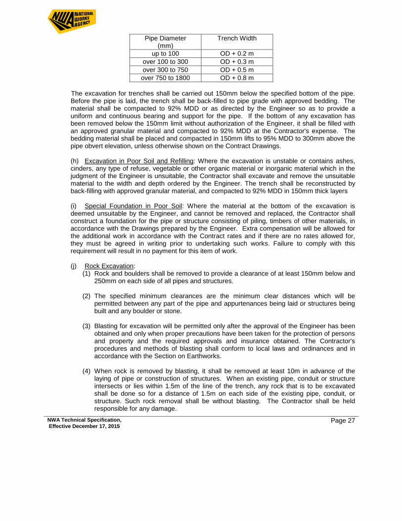
NWA Technical Specification, Effective December 17, 2015 Page 27
Pipe Diameter (mm)
Trench Width
up to 100 OD + 0.2 m over 100 to 300 OD + 0.3 m over 300 to 750 OD + 0.5 m over 750 to 1800 OD + 0.8 m
The excavation for trenches shall be carried out 150mm below the specified bottom of the pipe.
Before the pipe is laid, the trench shall be back-filled to pipe grade with approved bedding. The material shall be compacted to 92% MDD or as directed by the Engineer so as to provide a uniform and continuous bearing and support for the pipe. If the bottom of any excavation has been removed below the 150mm limit without authorization of the Engineer, it shall be filled with an approved granular material and compacted to 92% MDD at the Contractor's expense. The bedding material shall be placed and compacted in 150mm lifts to 95% MDD to 300mm above the pipe obvert elevation, unless otherwise shown on the Contract Drawings.
(h) Excavation in Poor Soil and Refilling: Where the excavation is unstable or contains ashes, cinders, any type of refuse, vegetable or other organic material or inorganic material which in the judgment of the Engineer is unsuitable, the Contractor shall excavate and remove the unsuitable material to the width and depth ordered by the Engineer. The trench shall be reconstructed by back-filling with approved granular material, and compacted to 92% MDD in 150mm thick layers
(i) Special Foundation in Poor Soil: Where the material at the bottom of the excavation is
deemed unsuitable by the Engineer, and cannot be removed and replaced, the Contractor shall construct a foundation for the pipe or structure consisting of piling, timbers of other materials, in accordance with the Drawings prepared by the Engineer. Extra compensation will be allowed for the additional work in accordance with the Contract rates and if there are no rates allowed for, they must be agreed in writing prior to undertaking such works. Failure to comply with this requirement will result in no payment for this item of work.
(j) Rock Excavation:
(1) Rock and boulders shall be removed to provide a clearance of at least 150mm below and 250mm on each side of all pipes and structures.
(2) The specified minimum clearances are the minimum clear distances which will be
permitted between any part of the pipe and appurtenances being laid or structures being built and any boulder or stone.
(3) Blasting for excavation will be permitted only after the approval of the Engineer has been
obtained and only when proper precautions have been taken for the protection of persons and property and the required approvals and insurance obtained. The Contractor's procedures and methods of blasting shall conform to local laws and ordinances and in accordance with the Section on Earthworks.
(4) When rock is removed by blasting, it shall be removed at least 10m in advance of the
laying of pipe or construction of structures. When an existing pipe, conduit or structure intersects or lies within 1.5m of the line of the trench, any rock that is to be excavated shall be done so for a distance of 1.5m on each side of the existing pipe, conduit, or structure. Such rock removal shall be without blasting. The Contractor shall be held responsible for any damage.
NWA Technical Specification, Effective December 17, 2015 Page 28
(k) Bedding of Concrete Pipe: The pipe shall be bedded as shown on the Drawings, or as
directed by the Engineer, in accordance with the following requirements:
(1) Unless otherwise shown on the Drawings or permitted by the Engineer, the backfill shall be shaped to receive the bottom quadrant of the pipe barrel. In addition, bell holes shall be excavated so that after placement only the barrel of the pipe receives uniform bearing pressure from the trench bottom.
(2) Where pipe is not laid in trench, a uniformly firm bed shall be formed as specified above.
(3) All pipes shall be carefully laid, true to the lines and grades given, hubs upgrade and with
the spigot ends fully entered into the adjacent hubs. Joints in concrete pipe shall be caulked and filled with a Portland cement mortar. The joints in concrete shall be thoroughly wetted before making the mortar joint. Other types of joints such as those using a rubber gasket shall be made in accordance with the manufacturers and/or Engineers recommendations.
(4) Before succeeding sections of pipe are laid, the lower portions of the hub of the pipe shall
be filled on the inside with cement mortar of sufficient thickness to bring the abutting pipes flush and even. After the pipe is laid the remainder of the joints shall be filled with mortar and sufficient additional mortar used to form a bead around the joint. The inside of the joint shall be wiped and finished smooth. This is not necessary for gasketed pipe.
(5) If so ordered by the Engineer, any pipe which is not in true alignment or which shows any
settlement after laying shall be taken up and re-laid without additional compensation. (6) Where indicated on the Drawings or directed by the Engineer, existing pipe culverts or
drains shall be taken up and re-laid or extended and jointed and backfilled in the same manner as specified herein for new pipe culverts or drains. All damaged pipe shall be replaced.
(7) Where concrete bedding is required it shall be installed in accordance with the design
drawings and in accordance with the Concrete Specifications of this contract.
(l) Backfilling: (1) Backfill placed after the pipe has been bedded shall be material as shown on the
Drawings and specified herein. In general backfill shall be of a quality satisfactory to the Engineer and shall be free from large lumps, wood and other extraneous material.
(2) All backfill shall be placed in layers of not more than 150mm in depth after compaction
and shall be compacted to 95% MDD by means of mechanical tampers. Hand tampers shall be used only upon written permission of the Engineer. Unless otherwise ordered by the Engineer, the backfill shall be brought to the surface of the surrounding ground and neatly graded.
(3) All suitable material removed in carrying out the excavation may be used for backfill if
required. All surplus or unsuitable material shall be removed and disposed of offsite. Should additional material be required for back-filling, it may be obtained from elsewhere on site or off site as the Engineer may direct.
NWA Technical Specification, Effective December 17, 2015 Page 29
(4) Bedding placed around pipes shall be deposited on both sides to approximately the same elevation at the same time. Rock fill or boulders shall not be placed closer than 0.6m from the pipes.
7.5 INLET STRUCTURES (a) These structures shall be constructed in accordance with the requirements contained herein
and other applicable Sections of the Specifications for the character of the work involved. (b) Metal fittings shall be set in full mortar beds and secured as shown on the Drawings. (c) Inlet and outlet pipes shall extend through the walls for a sufficient distance beyond the
outside surface to allow for satisfactory connections. The joint between the pipe and the concrete wall shall be constructed so as to prevent leakage along the outer surface of the pipe. The pipe shall be cut flush with the inside face of the wall.
(d) All requirements that are contained in other sections of this Contract shall apply equally to the
work being carried out under this Section. 7.6 FINAL INSPECTION PRECEDING ACCEPTANCE (a) Final inspection of the work will include a visual inspection of each culvert or drain by looking
from end to end, or structure to structure, with the aid of reflected sunlight or an electric or flash-light.
(b) The pipe shall be laid straight and true to both line and grade; shall be free from cracks and from protruding joint materials and contain no deposits of sand, dirt or other materials which will reduce the full cross-sectional area. Wall joints shall be tight. All finished work shall be neat in appearance and of first-class workmanship.
(c) The Contractor shall furnish labour to assist the Engineer in this inspection. The cost of this
assistance is deemed to be included in the rates for pipe laying. 7.7 CLEANING UP (a) As the work progresses, the Contractor shall clean up the site and the backfill shall be
rounded within the limits of the excavation. Soft trenches shall be marked and protected with signs and adequate lights. Any settlement shall be promptly refilled.
(b) The interior of all culverts, pipe drains, drop inlets and manholes etc. shall be cleaned of all
dirt, rubbish, and superfluous mortar as the work proceeds, and shall be left clean and to the satisfaction of the Engineer upon completion of the work,.
(c) If during the above mentioned cleaning any broken pipes are discovered they shall
immediately be removed and disposed of offsite and replaced to the satisfaction of the Engineer and at the Contractor's expense.
7.8 RESTORATION OF DAMAGED SURFACES AND PROPERTY (a) The Contractor shall restore or replace all removed or damaged paving, kerbs, sidewalks,
gutters, shrubbery, fences, or other disturbed surfaces or structures in a condition equal to or
NWA Technical Specification, Effective December 17, 2015 Page 30
better that before the work began and to the satisfaction of the Engineer and shall furnish all labour and material incidental thereto. In restoring improved surfaces, only new materials and pavement shall be laid.
(b) Except as may be specifically provided elsewhere in the Contract Documents, no separate
payment will be made for restoration and maintenance of pavement, damaged surfaces and property but the cost thereof shall be included by the Contractor in the item or items covering this particular part of the work.
7.9 PAYMENT
(a) Costs for bushing and to provide access to install pipes are to be included in the rates to install pipes and appurtenances unless otherwise provided for in the Bills of Quantities.
(b) Payment for concrete and plastic drainage pipes shall be per metre of pipe laid. The price shall include all excavation, disposal of surplus material, grading, de-watering, approved bedding and backfill, jointing, and testing of pipes. Pipe measurements shall be to the center of manholes or structures.
(c) Manholes shall be paid for as a lump sum. The price shall include all excavation, disposal of surplus material, dewatering, concrete work and precast or insitu sections, benching, connection of pipes, formwork, finishes, rebar, step irons, base, slab, frame and cover, testing and adjustments to final grade.
(d) Inlet, outlet and other structures shall be paid for as a lump sum unless otherwise specified in the Bills of Quantities. The price shall include all excavation, disposal of surplus material, dewatering, grading, concrete work, benching, connection of pipes, form-work, finishes, re-bar, step irons, frame and cover, specified grates and adjustments to final grade as applicable. (e) Concrete used for bedding shall be paid for at the cubic metre price bid. The price is to include all costs of supply, forming and placing and curing respective class of concrete. (f) Payment for rock shall be as an Extra Over item to earth excavation as shown in the Bill of Quantities. It shall be calculated on the actual amount of rock removed from the design trench.
(g) After pipes have been laid, jointed, bedded back-filled and trenches compacted, payment of an amount of 80% of the bid rate on this item will be made. The Contractor shall note that joints may be left open until the visual inspection takes place.
(h) On completion of backfilling and compaction to finished ground or road sub-grade, payment of 100% of the bid rate will be made. Here all trenches and excavations must be back-filled, graded and surplus material disposed of off site. (i) After manholes have been installed with pipe connections, benching, step irons, cover slab and frame and cover installed at the correct location, payment of an amount of 80% of the bid rate on this item will be made. (j) On completion of adjustment of frame and cover to finished ground or elevation as specified or adjustment to final road grade (tolerance +/- 5mm), payment of 100% of the bid amount will be made.
NWA Technical Specification, Effective December 17, 2015 Page 31
8.0 STRUCTURAL STEELWORK
8.1 GENERAL
The Contractor shall erect the steelwork, remove the temporary construction, and do all work required to complete the steel work, all in accordance with the plans and these specifications.
General standards f or structural steel work not included in the under mentioned paragraph as established by AASHTO - latest adoption shall finally govern all work including field erection, bolting, splicing and painting of steel work. A copy of the latest AASHTO is available for reading upon request
8.2 SUPPLY OF MATERIAL
All materials incorporated in the finished structure will be supplied to the Contractor free of charge. The Contractor shall be responsible for taking delivery at N.W.A. Tarrant Stores, Kingston, loading and transporting to site, unloading, sorting, and being responsible for safe custody returning to N.W.A Tarrant Stores, all surplus items.
8.3 HANDLING AND STORING MATERIALS
Materials to be stored shall be placed on skids above the ground. It shall be kept clean and property drained. Girders and beams shall be placed upright and shored. Long members, such as columns and chords, shall be supported on skids placed near enough together to prevent injury from deflection. If the contract is for erection only, the Contractor shall check the material turned over to him and report promptly in writing any shortage r injury discovered. He shall be responsible for the loss of any materials while in his care, or for any damage caused to it after being received by him
8.4 PLANT
The Contractor shall provide the falsework and all tools, machinery and appliances, including drift pins and fitting up bolts, necessary f or the expeditious handling of the work.
8.5 FALSEWORK
False-work, if required, shall be properly designed and substantially constructed and maintained for the loads which will come upon it. Detail drawings of the false-work shall be submitted to the S.O. for approval prior to erection, but in no case shall the Contractor be relieved of responsibility for results obtained by the use of these plans. Upon completion of the erection and before final acceptance, the Contractor shall remove all false-work, excavated or useless materials, rubbish and temporary buildings, replace or renew any fences damaged and restore in an acceptable manner all property, both public and private, which may have been damaged during the execution of this work, and shall leave the bridge site and adjacent highway in a neat and presentable condition, satisfactory to the S.O. All excavation, material or false-work placed in the stream channel during construction shall be removed by the Contractor before final acceptance.
NWA Technical Specification, Effective December 17, 2015 Page 32
8.6 METHODS AND EQUIPMENT.
Before starting the work of erection, the Contractor shall inform the S.O. fully as to the method of erection he propose to follow, and the amount and character of equipment he proposes to use, which shall be subject to the approval of the S.O. The approval of the S.O shall not be considered as relieving the Contractor of the responsibility for the safety of his method or equipment or from carrying out the work in full accordance with the plans and specifications. No work shall be done until such approval by the S.O. has been obtained.
8.7 BEARING AND ANCHORAGE
Bearing plates shall not be placed upon bridges seat bearing areas that are improperly finished, deformed or irregular. Bearing plates shall be set level in exact position and shall have a full and even bearing upon the concrete as shown on the plans. The contractor shall drill the holes and set the anchor bolts, except where the bolts are built into the concrete. The bolts shall be set accurately and fixed with Portland Cement grout completely filling the holes. The location of the anchor bolts in relation to the slotted holes in the expansion shoes shall correspond with the temperature at the time of erection. The nuts on anchor bolts at the expansion ends of spans shall be adjusted to permit the free movement of the span.
8.8 STRAIGHTENING BENT MATERIAL
The straightening of plates and angles or other shapes shall be done by methods not likely to produce fracture or other injury. The metal shall not be heated unless permitted by the S.O, in which case the heating shall not be to a higher temperature than that producing a dark “cherry red” colour. After heating, the metal shall be cooled as slowly as possible Following the straightening of a bend or buckle, the surface of the metal shall be carefully inspected for evidence of fracture. Sharp kinks and bends may be caused for the rejection of the material
8.9 ASSEMBLY
The parts shall be accurately assembled as shown on the drawings and any match-marks shall be followed. The material shall be carefully handled so that no parts will be bent, broken or otherwise damaged. Hammering which will injure or distort the members shall not be done. Bearing surfaces and surfaces to be in permanent contact shall be cleaned before the members are assembled. Bolts in splices or butt joints or compression members shall not be tightened until the span has been swung. Splices and field connections shall have all the holes filled with bolts and cylindrical erections pins (half bolts and half pins) before bolting Fitting-up bolts shall be of the same nominal diameter as the bolts, and cylindrical erection pins shall be 2 mm larger. Tightening of bolts to progress from the most rigid part of the joint towards the free edges. During tightening, either the bolt head or the nut may be turned while the opposite part is prevented from turning by hand wrench
N B Before commencement of the steelwork erection (including field splicing) and during the erection procedure, if he so requests, the S.O. shall be provided with the documentation prepared by an approved authority verifying the accuracy of any bolt tension/torque measuring device used by the contractor
NWA Technical Specification, Effective December 17, 2015 Page 33
8.10 ABUTTING JOINT
Abutting joints in compression members and girder flanges and in tension members where so specified on the drawings, shall be faced, and brought to an even bearing. Where joints are not faced the opening shall not exceed 6mm
8.11 BOLTED PARTS
Bolted parts shall fit together solidly when assembled and shall not be separated by gaskets or any other interposed compressible material. The nominal diameter of a hole shall be not more than 2mm greater that the nominal bolt size except that, if approved, holes may be made 3mmlarger in diameter than the nominal bolt size or slotted holes may be used where necessary, provided that any effects resulting from oversize holes are allowed for in the design. When assembled, all joint surfaces, including those adjacent to bolt heads, nuts and washers shall be free of scale (tight mill scale excepted) burrs, dirt and foreign material which would prevent solid seating of the parts. Each bolt shall be tightened to provided, when all bolts in the joint are tight, at least the minimum bolt tension given in Table 10 or the size and type of bolt used. Impact wrenches, if used, shall be of adequate capacity and sufficiently supplied with air to perform the required tightening of each bolt in approximately ten seconds. A 325 and A 490 bolts shall have a flat hardened washer under the element (nut or bolt head) turned in tightening. If necessary, bolts in slotted holes shall be installed with sufficient additional washers to distribute bearing stress under the head and nut.
Bevelled washers shall be used to compensate for lack of parallelism where, in the case of A 325 bolts, an outer face of bolted parts has more than a five per cent (5%) slope with respect to a plane normal to the bolt axis. In the case of A 490 bolts bevelled washers shall be used to compensate for any lack of parallelism due to slope of outer faces.
8.12 INSPECTION
Installation of bolts shall be observed to ascertained that a proper tightening procedure is employed. The turned element of all bolts shall be visually examined for evidence that they have been tightened. For verification of bolt tension, one of the following inspection methods shall be used unless otherwise specified
8.13 GENERAL METHOD
This method may be used for bolts in both friction-type and bearing-type joints and for bolts subject primarily to applied tension. The inspector shall use an inspection wrench which shall be a manual or power torque wrench capable of indicating a selected torque value.
NWA Technical Specification, Effective December 17, 2015 Page 34
Three (3) bolts of the same grade size and condition as those under inspection shall be placed individually in a calibration device capable of indicating bolt tension. The surface under the part to be turned in tightening each bolt shall be similar to that under the corresponding part in the structure, i.e. there shall be a washer under the part turned if washers are so used in the structure or, if no washer is used, the material abutting the part turned shall be of the same specification as that in the structure.
*Length may be any length representative of bolts used in the structure When the inspection wrench is a manual wrench, each bolt specified in paragraph (2) above shall be tightened in the calibration device by any convenient means to the minimum tension specified for its size in Table 10. The inspection wrench then shall be applied to the tightened bolt, and the torque necessary to turn the nut or head five (5) degree (approximately 25mm at 300mm radius) in the tightening direction shall be determined. The average torque measured in the tests of three bolts shall be taken as the job inspection torque to be used in the manner specified in paragraph (5) below.
When the inspection wrench is a power wrench it shall be adjusted so that it will tighten each bolt specified in paragraph (ii) above to a tension at least five (5) percent but not more than ten (10) percent greater than the minimum tension specified for its size in Table 10. The setting of wrench shall be taken as the job inspection torque to be used in the manner specified in paragraph (5) below. Bolts represented by the sample prescribed in paragraph (2) above which have been tightened in the structure shall be inspected by applying with the inspection wrench, in the tightening direction, the job inspection torque to ten percent (10%) of the bolts but less than two (2) bolts selected at random in each connection. If no nut or bolt head is turned by the application of the job inspection torque, this connection shall be accepted as properly tightened. If any nut or bolt head is turned by this application of the job inspection torque, this connection shall be accepted as properly tightened. Then if any nut or bolt head is turned by this application of the job inspection torque, this torque shall be applied to all bolts in the connection. If further nuts or bolts heads in the connection are turned by application of the job inspection torque and it appears evident that the bolts have been tightened beyond the snug condition, the inspector shall request the fabricator or erector to install in the connection, a new bolt of similar size and condition to those previously installed. The new shall be tightened under the observation of the inspector by rotating the turned element the amount from snug given in Table 2 after which the inspector shall apply the job inspection torque to the new bolt. If the nut or bolt head of the new bolt is turned by application of the job inspection torque, the inspector shall recalibrator the inspection wrench before proceeding with further inspection. If the nut or bolt head of the new bolt is not turned by application of the job inspection torque, all bolts in the connection whose nut or head is turned by the job inspection torque shall be tightened and re-inspected. Alternatively, if it appears evident that the bolts in the connection have not been tightened beyond the snug condition, the fabricator or erector shall tighten all the bolts in the connection and then resubmit the connection for inspection. Care shall be exercised by the inspector to ensure that bolts which have been adequately more than 15 degrees of additional rotation of the turned element when being inspected
NWA Technical Specification, Effective December 17, 2015 Page 35
8.14 SIMPLIFIED METHOD This method may be used for bolts on joints where a washer is used under the turned element. Bolts shall not be galvanized. The inspector shall use an inspection wrench which shall be a manual or power torque wrench capable of indicating a selected torque value.
Bolts which have been tightened in the structure shall be inspected by applying with the inspection wrench, in the tightening direction, the applicable job of inspection torque given in Table 12 to 10 percent of the bolts but not less than two bolts, selected at random in each connection. If no nut or bolt head is turned by this application of the job inspection torque, the connection shall be accepted as properly tightened. If any nut or bolt head is turned by the application of the job inspection torque, this torque shall be applied to all bolts in the connection, and all bolts whose nut or head is turned by the job inspection torque shall be tightened and re-inspected, or alternatively, the fabricator or erector, at his option may re- tighten all the bolts in the connection and then re-submit the connection for the specified inspection
TABLE 10 BOLT TENSION
Bolt Size Minimum Bolt Tension* (kN) Millimetres
A 325 Bolts A 490 Bolts
12 53 67
16 85 107
18.75 125 156
20 174 218
25 227 240
30 250 356
32 316 453
35 378 538
32 458 658
44 - 890
50 - 1165
Over 50 - 0.70 T.S.
*Equal to 70 percent of specified minimum tensile strength given in ASTM Standard A 325 and A 490, rounded off to the nearest kN.
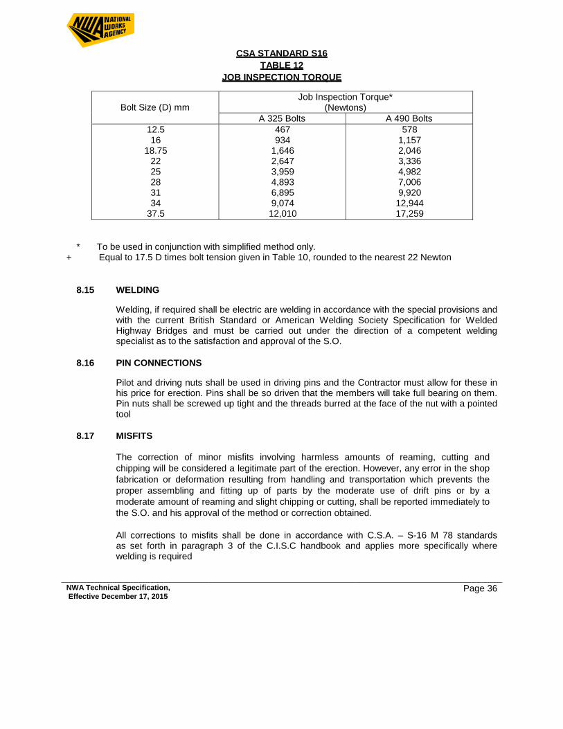
NWA Technical Specification, Effective December 17, 2015 Page 36
CSA STANDARD S16 TABLE 12
JOB INSPECTION TORQUE
Bolt Size (D) mm
Job Inspection Torque* (Newtons)
A 325 Bolts A 490 Bolts 12.5 16
18.75 22 25 28 31 34
37.5
467 934
1,646 2,647 3,959 4,893 6,895 9,074 12,010
578 1,157 2,046 3,336 4,982 7,006 9,920 12,944 17,259
* To be used in conjunction with simplified method only. + Equal to 17.5 D times bolt tension given in Table 10, rounded to the nearest 22 Newton
8.15 WELDING
Welding, if required shall be electric are welding in accordance with the special provisions and with the current British Standard or American Welding Society Specification for Welded Highway Bridges and must be carried out under the direction of a competent welding specialist as to the satisfaction and approval of the S.O.
8.16 PIN CONNECTIONS
Pilot and driving nuts shall be used in driving pins and the Contractor must allow for these in his price for erection. Pins shall be so driven that the members will take full bearing on them. Pin nuts shall be screwed up tight and the threads burred at the face of the nut with a pointed tool
8.17 MISFITS
The correction of minor misfits involving harmless amounts of reaming, cutting and chipping will be considered a legitimate part of the erection. However, any error in the shop fabrication or deformation resulting from handling and transportation which prevents the proper assembling and fitting up of parts by the moderate use of drift pins or by a moderate amount of reaming and slight chipping or cutting, shall be reported immediately to the S.O. and his approval of the method or correction obtained. All corrections to misfits shall be done in accordance with C.S.A. – S-16 M 78 standards as set forth in paragraph 3 of the C.I.S.C handbook and applies more specifically where welding is required
NWA Technical Specification, Effective December 17, 2015 Page 37
9.0 DRIVING OF STEEL “H” PILE SECTIONS
9.1 DESCRIPTION
The work contained in this contract consists of furnishing all necessary labour, plant and equipment to;
a) Inspect condition of piles at N.W.A. Tarrant Stores, and prior to receiving, report to the
N.W.A. Project Officer, any defective or substandard conditions/units.
b) Load and transport piles and accessories from N.W.A. Tarrant Stores, to the designated jobsite.
Handle piles so as not to damage the units or their coatings. Handling methods will
require the written approval of the Site Officer d) Store piles on site in a manner to prevent them (including coating materials) from being
damaged by natural elements and/or vandalism. Storage methods will require the approval of the Site Officer
e) Repair coatings or repair/replace piles damaged by handling in delivery, during storage
on site, or during pitching. Repair to the satisfaction of the Site Officer and at no additional cost to the employer.
f) Layout pile locations from controls established in the field by the Authority. The
Contractor is to verify the accuracy of these employer established control points. g) Excavate and/or fill to the elevations and limits specified on the contract, drawings. h) Drive piles at locations and to elevations and/or sets shown on the contract drawings
arid as specified herein. i) Re-drive piles as specified in Section 9.5
j) Cut off piles as described herein.
k) Return to the N.W.A. Tarrant Stores, all surplus lengths of piles 1500mm and longer.
l) Leave the site in a condition as good as that existing at the outset of the work.
m) Provide temporary excavations, fills, dewatering, and temporary structures (erection and demolition) as necessary to complete the work.
9.2 GENERAL
Materials and plant used shall he sufficient for performance of the work. Written approval of the use of any material or equipment must be obtained by the contractor from the Site Officer prior to its being incorporated in the work or used in its execution.
NWA Technical Specification, Effective December 17, 2015 Page 38
All costs associated with materials and plant other than those collected by the contractor from N.W.A Stores or specified in the Bill of Quantities of this contract will he deemed to be included in the rates quoted unless otherwise specified in this document
The contractor’ s procedures arid equipment used in the performance of the work shall reflect safe practice necessary to ensure protection of the general public, construction and inspection personnel, and adjacent properties and structures, and N.W.A. supplied materials.
The contractor shall submit a planned schedule and sequence for completion of the work. The proposed work schedule and sequence will require the written approval of the Site Officer prior to mobilizing to the site.
Notice of intention to drive the first pile at each pier or abutment shall be given to the Construction Engineer at least 24 hours prior to commencing driving in order to afford the Employers Geotechnical Engineer opportunity to be present at the driving.
No piles shall be driven without the immediate supervision of the Site Officer
The Site Officer must approve in writing final driving of each pile prior to the contractor’s demobilizing of equipment and personnel from a pier or abutment.
Measurement of claims for payment shall be according to the rates quoted in the Bill of Quantities. Measurement of claims for payment shall be provided by the contractor and will require written verification by the Site Officer prior to submission to the Senior Quantity Surveyor, National Works Agency for certification.
Welding shall be completed in accordance with CSA — W59 (Latest edition)
9.3 EQUIPMENT
a) Hammer
The contractor shall provide a hammer for driving of production or test piles that is rated at a minimum of 89kN per blow. Hammers shall have a ram weighing not less that kN and a stroke (or equivalent stroke) not exceeding metres unless otherwise notified in writing by the Site Officer. The contractor shall provide a hammer or adjust his driving assembly, to facilitate a 50% reduction of the above driving energy in accordance with Section 9.5 Item “j, “ii” of this specification.
The contractor shall submit information for each hammer to be used in the works with his tender documents. The information shall be presented on the appended, Form A - “Description of Equipment”. The contractor shall specify the manner in which he proposes to achieve a 50% reduction of driving energy.
NWA Technical Specification, Effective December 17, 2015 Page 39
Drop hammers shall not be used to advance production or test piles unless approval is given on the Drawings or as required to achieve the requirements of Section 10.5 Item “j, ii”. The contractor may use drop hammers for the construction of temporary works necessary for his own purposes.
b) GUIDES/ LEADS
Guides and leads shall be constructed to provide pile support at not less than two points on each pile as it is driven. Guides and leads shall be used throughout the driving of all piles with the exception of re-driving as discussed in Section 9.5 Items “ i”, “k”, and “l”. Guides/leads shall be held at the top and bottom with grips, braces, spuds, or other approved means. The contractor shall specify with his tender documents, the manner in which the guides and leads shall be supported during driving. The contractor shall submit a description of the guides and leads to be used in the works with his tender documents. Information shall be presented on the appended Form A - “Description of Equipment”. Followers shall not be permitted without written permission from the Site Officer
c) CAPBLOCK AND CUSHION
The contractor shall provide details of his cap-block(s) and cushions on the appended Form A - “Description of Equipment”. Information shall be submitted with his tender documents. Cap-blocks and/or cushions shall not be incorporated into the driving assembly without the written approval of the Site Officer.
d) AUGERS AND WATER JETS
The use of augers and water jets shall not normally be permitted. Under specific conditions their use may be permitted but at no additional cost to the employer and only with written permission from the Site Officer.
9.4 SITE PREPARATION / CLOSE-OUT a) The contractor shall provide temporary excavations, dewatering, fills, material and
equipment storage, and site offices and services as necessary to complete his work to the criteria specified herein and within the contracted schedule. Payment for such work shall be included in the rates quoted in the Bill of Quantities.
b) The contractor shall organize at the outset of the contract the movement of all electrical,
telephone, water or other utilities, services or structures as included in the Bill of Quantities. Movement of these lines will be considered an integral part of the contract and no payment will be considered for delays incurred as a result of the movement of these utilities.
c) The contractor shall complete excavations to the lines and grades specified on the
contract drawings prior to driving piles. Dewatering of the excavations shall be to the extent necessary to complete pile cut offs. Materials and procedures shall be in accordance with these specifications and where described in the measured works
NWA Technical Specification, Effective December 17, 2015 Page 40
schedule. d) The contractor shall backfill excavations and grade the site as required on the drawings. Materials and procedures shall be in accordance with these specifications and where
described in the measured works schedule - Bill No. 3 of these Bills of Quantities. e) The contractor shall remove all debris accumulated at the site as a result of the work. Written acceptance of the site’s condition must be received from the Site Officer
prior to complete demobilization of the contractor’s equipment and labour force.
9.5 METHOD OF DRIVING
a) Prior to driving, pile tips and heads shall be trimmed to even and square surfaces, free of bends and twists in the flanges and web. Each head shall be maintained in its trimmed condition during driving at no additional cost to the employer. b) Full length piles shall be used where possible. Where necessary, splicing of piles may be permitted by the Site Officer The method, position and quality of splicing shall be as shown on the contract drawings or as designated in writing by the Site Officer c) Prior to pitching, the contractor shall mark each foot of the pile to be driven past a datum selected by the Site Officer Furthermore, at the anticipated completion of initial driving or re-driving, the contractor shall provide pauses in his operations of sufficient duration to allow the Site Officer to layout inch markings on the face of the pile over the last foot of length to be driven.
d) The piles shall be held securely and accurately in specified positions with approved guides/leads.
e) Piles shall not be forced into acceptable location by the application of lateral loads
during driving once the pile unit has achieved --------% of its design penetration. f) The hammer blow shall be delivered in the direct axis of the pile. g) Piles shall be driven to the tip elevations specified on the drawings and subject to the
provisions of clauses “i and “j” of this section and Section 6.0 h) Accumulated interruptions in the driving of piles shall not be allowed to exceed one (1)
hour after the pile is within metres of its design tip elevation. The Site Officer will have the right to redefine the set criteria and/or design tip elevation at no cost to the contract should it become necessary for the contractor to violate this clause due to his scheduling of the work or equipment breakdown.
i) Following the driving of each pile, the head elevation of that pile shall be recorded by the
contractor and reported in writing to the Site Officer Following completion of driving of all 25mm shall be re-driven as per item “1”.
NWA Technical Specification, Effective December 17, 2015 Page 41
j) In the event of a pile “hanging up” because of meeting an obstruction or dense/hard soil conditions prior to reaching its specified tip elevation, the following procedure shall be followed:
(NOTE: Cited blows assume use of a diesel hammer rated at 89 kN energy and operating at 60% efficiency. The Site Officer reserves the right to redefine the blow counts specified below to reflect the type and efficiency of the driving assembly actually provided by the contractor)
i) The pile shall be driven with the hammer delivering its full rated energy to the pile
for up to 200 continuous blows but not more than 50 blows if there is no pile advance. If the obstruction is not passed then
ii) The pile shall be driven with the hammer delivering 50% of its rated energy for up to
400 continuous blows but not more than 100 blows if there is no pile advance. If the obstruction is not passed, then
iii) The drive will be terminated and the pile accepted in accordance with the criteria
stipulated in Section 9.6.
iv) An alternate pile or piles will be driven if so directed by the Site Officer Payment for additional piles will be made on the basis of the measured units of work completed at the rates quoted for initial driving of production piles in the Bill of Quantities
k) Up to 20% of the piles initially placed at each abutment or pier will be re-driven following a
period of not less than forty-eight (48) hours subsequent to the completion of initial driving of all piles in that abutment or pier. The actual units to be re-driven will be selected by the Site Officer Re-driving will be at the full capability of the hammer and to the number of blows delivered in the advance of the last 75mm of the initial phase of driving. Re-driving will not exceed 50 blows if there is no pile advance. If the re-driving record of any of the selected piles varies from the last record of the initial phase of driving by more than ——— %, the Site Officer may require re-driving of all piles in the abutment or pier. Re-driving will be to the upper limits of the criteria defined in Section 9.6 item “d”.
m) Payment for re-driving will be at the units and rates set forth in the Bill of Quantities.
n) If required in the Bills of Quantities or as directed by the Site Officer, piles will be cut off at
the elevation indicated on the drawings or by the Site Officer Piles will be cut off evenly, level, and tension plates affixed as per the contract drawings. No part of the pile head left in the work is to be damaged following cut off. If damage at or below the cut off location occurs during driving, the contractor will affect repairs to the satisfaction of the Site Officer at no cost to the Employer.
9.6 ACCEPTANCE OF PILE DRIVING
Installation of each pile will be subject to approval of the Site Officer who shall be the sole judge of acceptability with respect to final driving resistance, depth of penetration, alignment, location, or any recognized static or dynamic criteria used to determine bearing capacity.
NWA Technical Specification, Effective December 17, 2015 Page 42
The following tolerances will be used in establishing a pile’s acceptability:
a) Position of any pile is to be within three inches of its specified position in plan at the specified cut off level.
b) Piles shall be driven with a variation of not more than 20mm/m from the specified batter. c) Rotation of the entire pile unit from its prescribed orientation is not to exceed 20% of
the pile’s flange width.
d) For the purposes of assisting the contractor in preparation of his tender, the following RANGE of driving resistances will be used in establishing the acceptability of any pile. This information does not supersede the requirement to achieve the specified pile tip elevation but will be used to establish set should the pile be judged by the Site Officer not to have achieved sufficient axial capacity on reaching the design tip elevation.
(NOTE: Cited blows assume a diesel hammer rated at 89kN energy and operating at 60% efficiency. The Site Officer reserves the right to redefine the blow counts listed below to reflect the type and efficiency of the driving assembly actually provided by the contractor)
i) 120 blows/foot for 5 successive feet ii) 15 blows/foot for 10 successive inches iii) 20 blows/inch for 6 successive inches iv) 20 blows for no pile advance
e) Any pile damaged by improper driving; or driven outside of the criteria set out in
Section 9. 5 items a, b, c; or driven without the written permission of the Site Officer to a head level below that fixed by the plans shall be corrected at the Contractor’s expense by one of the following methods approved by the Site Officer for the pile in question.
i) The pile shall be withdrawn and replaced by a new and, if necessary, a longer pile.
ii) The rejected pile will be cut off at an elevation 600mm below the proposed
underside of pile cap level, and an additional pile supplied, pitched and driven to specification to replace the rejected pile.
f) Load Tests shall be performed to the specifications of ASTM D 1143 (latest
edition) if required by the Site Officer Payment for the work will be in accordance with units and rates negotiated with the contractor as a variation to the contract.
g) Test Piles shall be driven at locations established by the Site Officer Payment
for pitching, driving, splicing and cutting off shall be at the units and rates quoted in the Bill of Quantities for production piles incorporated in the abutment or pier. Payment for moving and setting up of equipment, plant and materials at locations not otherwise stated in these Bills but which are deemed necessary for the driving of production piles will be at rates and units to be negotiated with the contractor.
NWA Technical Specification, Effective December 17, 2015 Page 43
9.7 MEASUREMENT FOR PAYMENT/RECORDS
a) Measurement of claims for payment shall be the responsibility of the contractor. However, written verification of the measured works will be required from the Site Officer prior to the settlement of any such claims. All measurement of claims for payment shall be in accordance with the items and the unit rates quoted in the Bills of Quantities.
b) Measurement for the Employer’s records shall be the responsibility of the Site
Officer Included will be records of:
i) driving energy and rate, equipment misfires, etc. ii) periods of work stoppage iii) pile reference as to length, location, date and time of driving, etc. iv) equipment and labour at site v) equipment breakdown and repair vi) splicing vii) weather conditions viii) final tip and cut off elevations; length of cut offs ix) pile alignment and orientation x) blows per foot driven xi) final set of each pile in blows per inch for up to 12 successive inches xii) results of re-driving.
10.0 ENVIRONMENTAL SPECIFICATION 10.1 PREAMBLE
These Environmental Specifications must be read in conjunction with applicable plans for environmental management and environmental permits issued by NEPA/or for control of erosion and sedimentation prevention and the rest of the documents forming the Contract and in conjunction with all applicable laws and regulations in effect at the time of execution of the Works. The Contractor shall not be absolved from complying with any provisions contained within any one of these documents on the grounds that the requirements stated in one of the documents are not repeated in the other. Furthermore, in the event of conflict between these specification requirements and any pollution control or other environmental laws, rules or regulations of other National, regional or local agencies the more restrictive specifications, laws, rules or regulations shall apply.
The Environmental Specifications contain approaches and protection measures to be implemented when dealing with environmentally sensitive areas such as wetlands and other aquatic resources, forest resources, wildlife habitats, heritage sites, coastal resources and local communities especially those with sensitive receptors (children and senior citizens and sick). It is the policy of the National Works Agency (NWA) to protect the environment from adverse effects resulting from all alterations on the National Road Network (NRN). As the executing agency for programs related to the NRN, the NWA will enforce this policy requirements (as they pertain to construction and maintenance operations) as part of its Contract management, quality assurance, inspection and audit functions. The applicable environmental protection and pollution prevention measures captioned below shall be implemented to maintain the integrity of the natural and manmade environment.
NWA Technical Specification, Effective December 17, 2015 Page 44
The bidding and contract documents for works to be performed will include the following general environmental and social conditions which will be implemented by the Contractor and monitored by the Engineer.
An Environmental Management Plan, Health and Safety Management Plan (Traffic Management
Included), Emergency Management and Spill Management and Contingency Plan must be provided by the Contractor for approval by the NWA to ensure that the environment will be protected during project implementation and some of the socio-economic impacts are managed.
10.2 POLLUTION CONTROL
The Contractor will take all precautionary measures throughout the duration of the project to prevent the contamination of water courses, aquifers and the marine environment by pollutant wastes such as chemical products, fuel, lubricants, sewerage water, silt or other obnoxious material. Waste water to be discharged from construction facilities must first be filtered or otherwise treated to eliminate obnoxious material likely to cause pollution into natural watercourses or aquifers or endanger indigenous flora and fauna. No waste water or other liquid or obnoxious material will be dumped on wetlands or breeding grounds of aquatic birds. The use of oil and grease separators to treat all discharge must be included in site plans and maintenance plans provided. If by accident the contractor dumps, discharges or spills any fuel or chemical product likely to contaminate any watercourse or aquifer, the contractor will immediately take action to arrest and eliminate the pollution caused thereby. The Contractor shall maintain written records of any such incident and of the mitigation measures implemented. Spill management kits acquisition must be apart of the management plan for all work sites. In the demolition of existing structures and the construction of new ones, the Contractor shall ensure that no rubble or other surplus construction material is dumped into existing watercourses or aquifer recharge areas. Construction activities on water courses or over aquifers or aquifer recharge areas will be confined to the areas shown in the final design drawings and where the erection of temporary or permanent structures have been so designated. Temporary fills and scaffolding or false works erected for the undertaking of construction works will be removed from river or watercourse beds immediately upon termination of the construction activities at such locations.
Frequent crossing by construction equipment over watercourse beds during construction activities
will not be permitted. If and when needed, temporary structures will be erected to allow crossings. The use of silt, sand or similar fine graded material which could cause turbidity or sedimentation in the stream shall not be permitted in the construction of stream crossings.
10.3 VEGETATION PROTECTION, REVEGETATION AND EROSION/SILTATION PREVENTION The Contractor will reduce loss of vegetative cover, erosion and sedimentation to the minimum
possible by:
NWA Technical Specification, Effective December 17, 2015 Page 45
(a) avoiding any off-the road driving outside the immediate construction areas; (b) keeping process areas as small as possible; (c) reducing damage to vegetation through environmentally sound construction practices; giving
special importance to the preservation of trees, particularly large trees of genetic and landscape value;
(d) where roadside banks are cut and exposed, protecting the banks from gully erosion and sedimentation into nearby streams.
(e) providing sediment traps and screens where needed; (f) excavating bulk fill from areas so as to minimize erosion, reduce visual impact of scarring
and allow for rapid re-vegetation following excavation; and (g) reusing organic topsoil. The Contractor will restore ground cover as soon as earthworks permit, and will take the
necessary measures to promote regeneration of native vegetation, even if such measures may not be immediately clear from the final designs. These measures may include the use of degradable geotextile, the use of seeds or live stakes of native grasses, re-vegetating with local shrub and tree species (especially those characterized by rapid growth and deep roots) and the reuse of top soil and mulch. The Contractor will replant shade trees and screening vegetation, as designated in the specific environmental mitigation plan.
To avoid erosion and gullying of banks, the Contractor will refrain from earthworks during the peak
of the rainy season, use gabions and miter drains, and will avoid angle termination at the borders of cuts and fills.
The Contractor will build temporary and permanent silt traps where the road crosses streams and
rivers or where the road traverses close to water courses, using appropriate materials and techniques, including settling ponds, silt fences, filter cloths and small scale wetlands, even if such measures may not be immediately clear from the final designs.
The Contractor will minimize earthwork in the vicinity of rivers/streams; work from banks rather
than from stream beds and in general reduce contact with watercourses to the minimum. On all bridge approaches the Contractor will sow the faces exposed to inclement weather with local grass or with other local species, especially those that are adapted to local conditions and which grow rapidly and have deep roots.
10.4 NOISE ABATEMENT Jamaica does not currently have specific noise level regulation, but the control of noise is
recognized within the Environmental Act as one method of protecting people's well-being. To this end the Contractor shall adapt the following conditions for noise reduction throughout project execution:
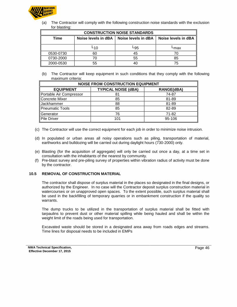
NWA Technical Specification, Effective December 17, 2015 Page 46
(a) The Contractor will comply with the following construction noise standards with the exclusion for blasting:
CONSTRUCTION NOISE STANDARDS Time Noise levels in dBA Noise levels in dBA Noise levels in dBA
L10 L95 Lmax 0530-0730 60 45 70 0730-2000 70 55 85 2000-0530 55 40 75
(b) The Contractor will keep equipment in such conditions that they comply with the following
maximum criteria: NOISE FROM CONSTRUCTION EQUIPMENT
EQUIPMENT TYPICAL NOISE (dBA) RANGE(dBA) Portable Air Compressor 81 74-87 Concrete Mixer 85 81-89 Jackhammer 88 81-89 Pneumatic Tools 85 82-89 Generator 76 71-82 Pile Driver 101 95-106
(c) The Contractor will use the correct equipment for each job in order to minimize noise intrusion.
(d) In populated or urban areas all noisy operations such as piling, transportation of material,
earthworks and bulldozing will be carried out during daylight hours (730-2000) only.
(e) Blasting (for the acquisition of aggregate) will only be carried out once a day, at a time set in consultation with the inhabitants of the nearest by community.
(f) Pre-blast survey and pre-piling survey of properties within vibration radius of activity must be done by the contractor.
10.5 REMOVAL OF CONSTRUCTION MATERIAL The contractor shall dispose of surplus material in the places so designated in the final designs, or
authorized by the Engineer. In no case will the Contractor deposit surplus construction material in watercourses or on unapproved open spaces. To the extent possible, such surplus material shall be used in the backfilling of temporary quarries or in embankment construction if the quality so warrants.
The dump trucks to be utilized in the transportation of surplus material shall be fitted with
tarpaulins to prevent dust or other material spilling while being hauled and shall be within the weight limit of the roads being used for transportation.
Excavated waste should be stored in a designated area away from roads edges and streams.
Time lines for disposal needs to be included in EMPs
NWA Technical Specification, Effective December 17, 2015 Page 47
10.6 REMOVAL OF EXISTING PAVEMENT The Contractor shall not dispose of used pavement material on the road or highway side, nor in
watercourses or wetlands. Such material shall be disposed of in places designated in the final designs or authorized by the Engineer.
Whenever large amounts of asphaltic material are to be removed from a road or highway, the
material shall be reused, if so provided in the plans, hauled to an approved facility for processing and future reuse, or disposed of by burial, at least at one meter depth, outside the project site and urban settlements at a location approved by the Engineer. However, old and out-of-service roads can be utilized as disposal areas, provided that it is determined and documented on the project permanent records that pollution risks are minimal, and with previous authorization of the Engineer.
10.7 BORROW AREAS AND QUARRIES In accordance with Jamaican law, the uses of any borrow areas for the purpose of this project will
be subject to the licensing requirements of National Environmental and Planning Agency (NEPA). The license will be granted on the basis of a quarry or borrow area management plan submitted by the Contractor. Such plan shall clearly show how environmental impacts will be mitigated, including erosion prevention and after-use restoration. Borrow sites and quarries must be assessed for environmental impact before use and a report submitted to NWA and NEPA for approval.
The following mitigation measures will be generally used to control erosion and other direct
impacts at borrow sites and quarries (a) cover gently-sloping or flat borrow sites with top soil and seed after termination of the use of
the site; (b) shape contour embankments to slow down run-off; (c) landscape the areas close to faces of vertical rocky borrow sites in the process of
exploitation; (d) make provisions for good borrow site management practices in contracts with private site
operators. The Contractor shall not extract river run stone, gravel, sand or any other construction material
from watercourse beds. In exceptional cases, prior authorization from the Engineer may be obtained, as well as the necessary permit or license by the pertinent governmental authority.
The Contractor shall not excavate borrow ditches or pits on flat lands subject to water stagnation
and/or with slow runoff drainage, and in proximity of villages or urban settlements. Whenever such exploitation becomes necessary, in addition to the pertinent permits, the contractor must prepare, and present for approval of the Engineer, a drainage plan based on a topographic survey drawn to a convenient scale.
NWA Technical Specification, Effective December 17, 2015 Page 48
10.8 CONSTRUCTION CAMPS, STORAGE FACILITIES, AND HEALTH AND SAFETY In accordance with Jamaican law, before establishing construction camps, the Contractor must
obtain a license from the MOT&W and NEPA. The license will be granted on the basis of a detailed design and a plan of operations submitted by the Contractor. Such plan shall clearly show how environmental and social impacts will be avoided and mitigated, including erosion and pollution controls, restoration of camp sites, health care facilities, preventative sanitation measures and provisions for physical check-ups. Each camp will provide separate clean boarding, sanitary and washing facilities for male and female workers.
The following mitigation measures will be generally used to control pollution, erosion and other
direct impacts at construction camps and storage facilities: (a) All sewage and waste water discharges will be collected and treated in an approved system
installed on site. Effluent discharges must meet applicable standards; (b) Solid waste will be stored in proper containers, collected and disposed of in dumps or
landfills approved by the NEPA. (c) Erosion will be minimized and sedimentation prevented through a drainage system with
sedimentation traps and/or screens; (d) All hydrocarbon storage facilities will be on impermeable surfaces and provided with
collection traps installed in the workshop area; (e) All refueling, servicing and washing facilities within the camp will be situated on impermeable
surfaces served by an oil trap, run-off collection system; (f) Trucks and earth moving equipment will be equipped with functioning back-up warning
devices; (g) Upon completion of the contract, all elements of the camp will be removed and the site, as
far as possible, will be returned to its original conditions unless designated for alternative uses with approval of NEPA.
The Contractor will provide medical examinations and emergency medical care for the
construction crew and will provide suitable and clean sanitary facilities and necessary safety equipment, including special masks covering nose and mouth, for employees when applicable. First Aid kits are essential for all sites (campsites and worksites). The Contractor will also provide clean potable water, food and housing when necessary.
The burning of materials in open air will be done under strict supervision of the Contractor’s
qualified staff. The Contractor will not burn tires, asphaltic materials, oil or any material that might produce smoke, either for the purpose of incineration or to augment the burning power of other matter. Extreme caution will be exerted to dispose of material so as to avoid damage or destruction of private property or to cause excessive air pollution.
Any measure applicable to the Contractor will automatically also apply to any sub-Contractor (e.g.
quarry operators) whenever relevant. Furthermore the labor contracts are to include a clause of consensus by the Contractor to abstain
from hunting and logging while under contract.
NWA Technical Specification, Effective December 17, 2015 Page 49
10.9 ASPHALT PLANT The Contractor shall install his asphalt mix production plant in flat land, cleared of organic topsoil
with suitable access for all types of vehicles, far from urban settlements and with prior approval of the Engineer. The plant installation shall provide adequate storage space for raw and surplus materials, and ample space for traffic circulation, thus to prevent hindrance to loading and unloading operations. Installation of asphalt mixing plants in private land shall not be authorized, unless written authorization is obtained from the owner or his legal representative.
The asphalt mix production plant shall be adjusted to operate in such a manner that, to the extent
possible, dust and fumes discharged to the surrounding area are kept to a minimum. The plant will be kept free of human and construction debris, and materials will be stored safely. Measures will be taken to assure that storm water run-off will not carry contaminants to adjacent watercourses, wetlands or sensitive vegetation.
In the transportation of hot mix asphalt, dump trucks shall be fitted with adequate devices to
prevent material spillage. In addition, existing local regulations for transportation of risky materials shall be observed.
10.10 BLASTING Blasting will be conducted in a safe manner with charges large enough to break up material, but
not so large as to damage adjacent structures and threaten human safety from shock and debris. Blasting will take place only during daylight hours and at a time acceptable to affected adjacent parties.
A pre-blast survey of areas sensitive to vibration must be done to ensure that claims of impact can
be verified. 10.11 PRIVATE LAND PERMIT The Contractor shall not dispose of any surplus material on private land unless authorized by the
owner in writing, authenticated before a Notary Public, and with previous authorization of the Engineer.
10.12 COMMUNITY RELATIONS The Contractor shall follow a work schedule, procedures and rules of conduct conducive to good
community relations during construction. This will entail adequate notification of work schedules for local communities and villages, and hiring practices which provide opportunities for local labor.
10.13 ARCHEOLOGICAL/CULTURAL The Contractor will allow archeological/cultural inspections during construction to facilitate
protection and recovery of archeological sites and artifacts, and protection of cultural/historical sites. Jamaica National Heritage Trust (JNHT) archaeologists will periodically monitor work and specific areas. Watching Briefs (guidelines to the Contractor to assist in identifying sites) will be
NWA Technical Specification, Effective December 17, 2015 Page 50
prepared for critical areas. Unearthing archeological features will result in work suspension, if necessary, in that area until features are recovered and/or the site is released by the JNHT.
10.14 MONITORING Monitoring of direct impacts will be carried out on a daily basis by the Contractor with periodic
verification monitoring by the Supervising Firm (NWA) and shall include, but not be restricted to, the following concerns:
Assessment of dust control measures implemented by the contractor; Measurement of noise levels arising from construction equipment and construction methods; Measurement of air quality in general and pollution levels from construction equipment
(exhaust in particular); Assessment of surface water treatment implemented by the contractor sites is carried out; Verification that the construction sites and camps are cleaned after construction; Verification that oils and petroleum are being stored properly Monitor silting and increased sediment loads to streams which the bridges cross; Installation of erosion control and drainage works (including silt traps); Prevention of damage to undiscovered significant archeological or historical findings; Verification of habitat and landscape protection; Ensuring that Contractor(s) follows a work schedule, procedures and rules of conduct
conducive to good community relations during construction. Staff welfare is being managed effectively – accidents and incidents are reported Verification of proper community relations
Where necessary, the Supervising Firm (NWA) will provide a brief orientation to the Contractor
and Staff on the environmental requirements. Monthly environmental monitoring reports will be expected from the Contractor to present the
result of monitoring and level of compliance to the NEPA permit issued for the project and the NWA’s requirement for environmental management. (Monitoring instruments should be included in Environmental Management Plan (EMP).

NWA Technical Specification, Effective December 17, 2015 Page 51
Appendix A
Test Summary Sheets (sample)
Gradation for concrete aggregates
Standards for structures
o Kerb and asphalt detail and access detail o Typical V-drain section o U-drain 1200*1200mm o Random rubble catch basin detail o Cross drain rip section and typical elevation o Manholes kerb inlet with sewer under sidewalk o Guard Rails
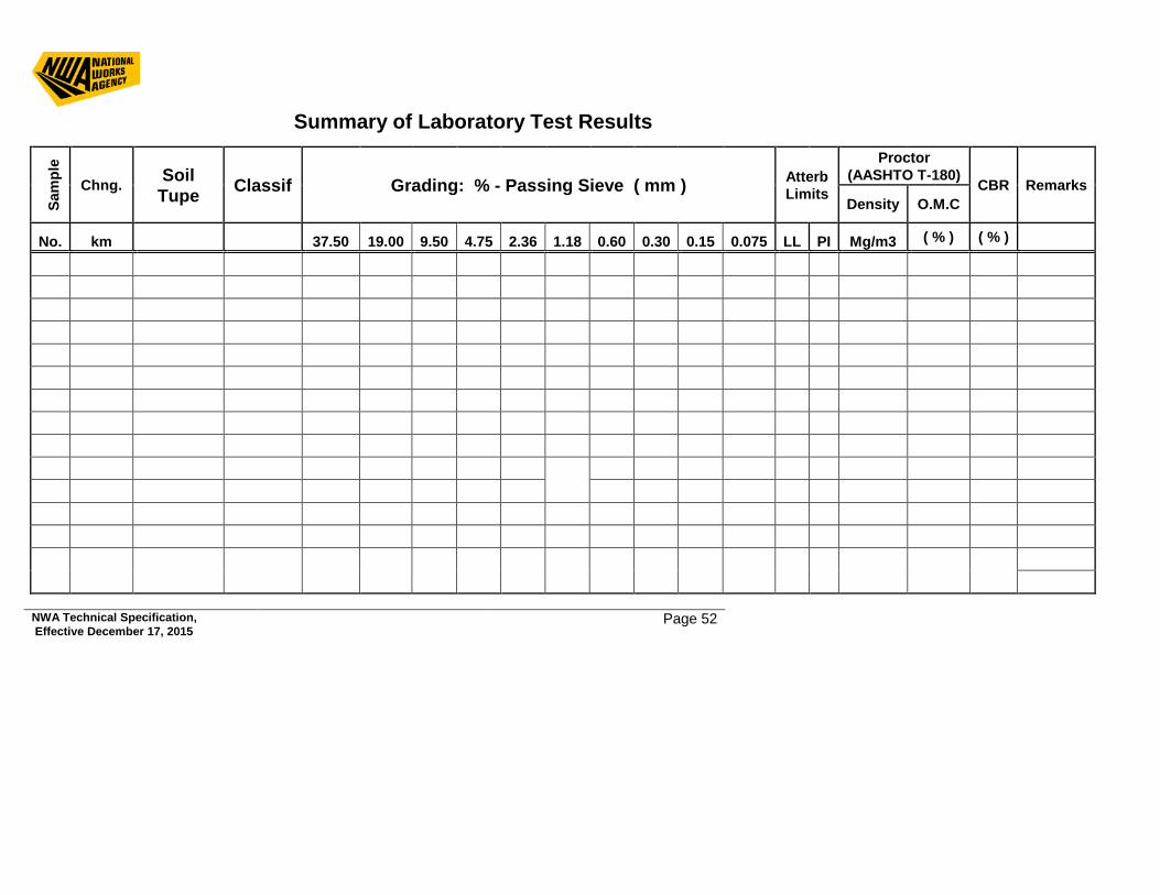
NWA Technical Specification, Effective December 17, 2015 Page 52
Summary of Laboratory Test Results
Sam
ple
Chng. Soil Tupe Classif Grading: % - Passing Sieve ( mm ) Atterb
Limits
Proctor (AASHTO T-180) CBR Remarks Density O.M.C
No. km 37.50 19.00 9.50 4.75 2.36 1.18 0.60 0.30 0.15 0.075 LL PI Mg/m3 ( % ) ( % )
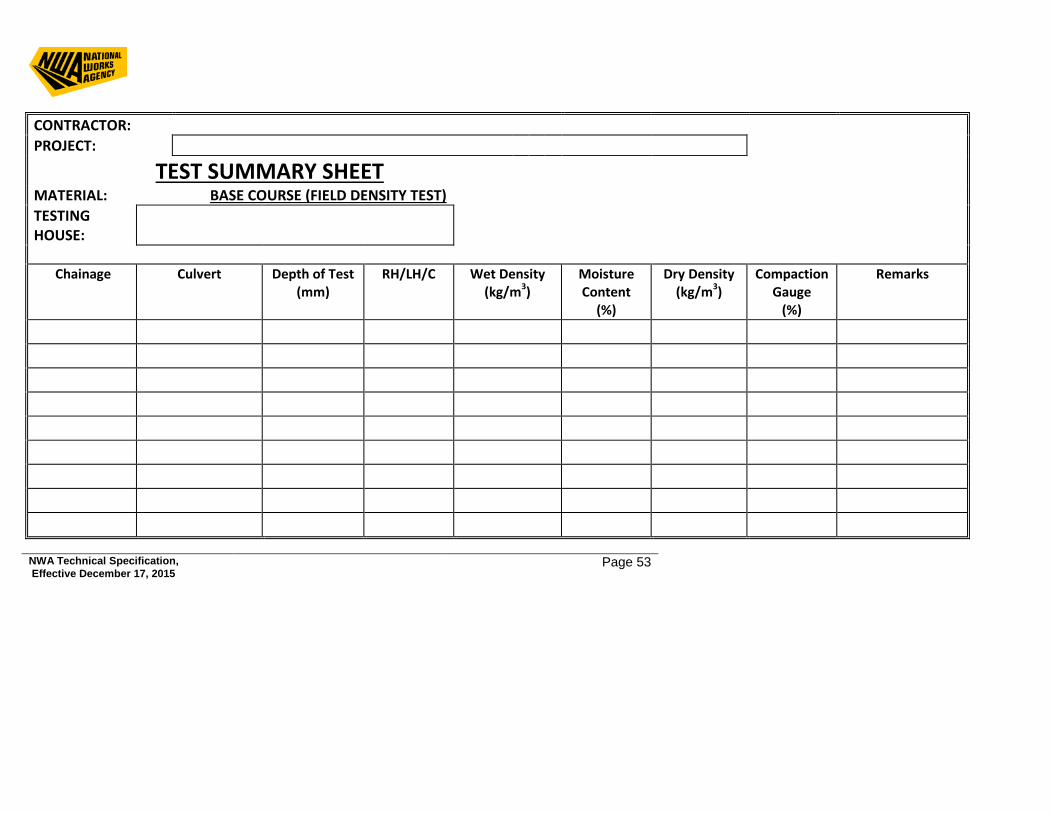
NWA Technical Specification, Effective December 17, 2015 Page 53
CONTRACTOR: PROJECT:
TEST SUMMARY SHEET MATERIAL: BASE COURSE (FIELD DENSITY TEST) TESTING HOUSE:
Chainage Culvert Depth of Test
(mm) RH/LH/C Wet Density
(kg/m3) Moisture Content
(%)
Dry Density (kg/m3)
Compaction Gauge
(%)
Remarks

NWA Technical Specification, Effective December 17, 2015 Page 54
NWA Technical Specification, Effective December 17, 2015 Page 55
CONTRACTOR PROJECT:
TEST SUMMARY SHEETS MATERIAL: ASPHALT CONCRETE TEST (REGULATION) TESTING HOUSE:
No.
Location
File
/ Sa
mpl
e N
o.
Mat
eria
l Ty
pe Sample
Date Grading (% Passing by Weight)
Bitu
men
Co
nten
t (%
) De
nsity
VIM
(%)
VFB
(%)
Stab
ility
(k
N)
Flow
Va
lue
19 mm
12.5 mm
9.5 mm
4.75 mm
2.36 mm
0.60 mm
0.30mm
0.15mm
0.075mm
SPEC 4A MAX. 100 100 100 75 50 29 23 16 10 6.5 5 85 4 MIN. 100 100 80 55 35 18 13 8 4 4.5 3 75 8 2
NWA Technical Specification, Effective December 17, 2015 Page 56
CONTRACTOR:
PROJECT:
TEST SUMMARY SHEETS MATERIAL: CONCRETE COMPRESSIVE STRENGTH RESULTS TESTING HOUSE:
Chainage Location Element Cylinder # Date
Casted Date
tested Age(days) Mass
(kg) Density (Kg/m³)
Load (KN)
Cylinder Strength
(MPa)
Cube Strength
(MPa)
Remarks
NWA Technical Specification, Effective December 17, 2015 Page 57
CONRETE AGGREGATES Coarse Coarse Sieve size mm
Percentage by mass passing BS sieves for nominal sizes Graded Aggregates Single-sized aggregate 40 mm to 5 mm
20 mm to 5 mm
14mm to 5 mm 40mm 20mm 14mm 10mm 5mm
50.0 100 - - 100 - - - - 37.5 90-100 100 - 85-100 100 - - - 20.0 35-70 90-100 100 0-25 85-100 100 - -
14.0 25-55 40-80 90-100 - 0-70 85-100 100 - 10.0 10-40 30-60 50-85 0-5 0-25 0-50 85-100 100 5.0 0-5 0-10 0-10 - 0-5 0-10 0-25 45-100
- - - - - - 0-5
All in one aggregate
Sieve size
Percentage by mass passing BS sieves for nominal sizes
40mm 20mm 10 mm 5mm 50 mm 100 - - -
37.5mm 95-100 100 - - 20mm 45-80 95-100 - - 14mm - - 100 -
Sand
Sieve Size
Percentage by mass passing BS sieve Overall Limits
Additional limits for grading C M F
10 mm 100 - - - 5 mm 89 - 100 - - -
2.36 mm 60 -100 60 - 100 65 -100 80 -100 1.8 mm 30 -100 30 - 90 45 -100 70 -100 600 um 15 -100 15 - 54 25 - 80 55 -100 300 um 5 - 70 5 - 40 5 - 48 5 -70 150 um 0 -15 - - -
NWA Technical Specification, Effective December 17, 2015 Page 58
10mm - - 95-100 100 5mm 25-50 35-55 30-65 70-100
2.36mm - - 20-50 25-100 1.18mm - - 15-40 15-45 600um 8-30 10-35 10-30 5-25 300um - - 5-15 3-20 150um 0-8 0-8 0-8 0-15
NWA Technical Specification, Effective December 17, 2015 Page 59
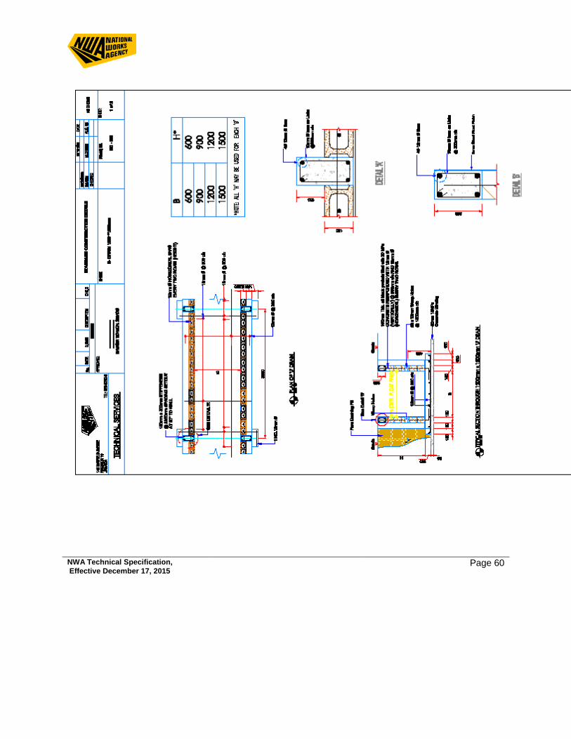
NWA Technical Specification, Effective December 17, 2015 Page 60
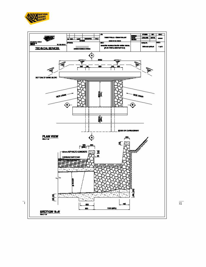
NWA Technical Specification, Effective December 17, 2015 Page 61
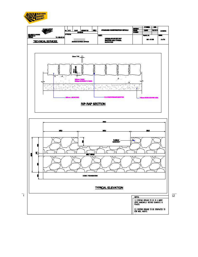
NWA Technical Specification, Effective December 17, 2015 Page 62
NWA Technical Specification, Effective December 17, 2015 Page 63
NWA Technical Specification, Effective December 17, 2015 Page 64