specifications manual - energy trust insider from energy trust of oregon’s home retrofit team the...
TRANSCRIPT

ENERGY TRUST OF OREGONHOME RETROFIT
2018SPECIFICATIONSMANUAL
energytrust.org Updated June 2018 Copyright © 2018 Energy Trust of Oregon Home Retrofit

Foreword from Energy Trust of Oregon’s Home Retrofit Team ............................................. 9
IN—INTRODUCTION ................................................................................................................................. 10
IN 1.0—Program Goals and Eligibility .............................................................................................................................. 10
IN 1.1—Code Compliance, National and Regional Standards ...................................................................................... 10
IN 1.2—Carbon Monoxide Alarms ...................................................................................................................................... 11
IN 1.3—Knob and Tube Wiring ............................................................................................................................................ 11
IN 1.4—Materials ................................................................................................................................................................... 11
IN 1.5—Foam Insulation ...................................................................................................................................................... 12
IN 1.6—Work Quality Verification Process ..................................................................................................................... 12
IN 1.7—Preapproval Waiver for Unusual Conditions ................................................................................................... 12
IN 1.8—Illustrations ............................................................................................................................................................. 12
IN 1.9—Human Contact Areas ........................................................................................................................................... 12
IN 1.10—Permits and Remodeling Projects .................................................................................................................... 12
IN 1.11—Equipment Maintenance ....................................................................................................................................... 13
IN 1.12—Combustion Appliance Safety ............................................................................................................................ 13
IN 1.13—Determination of Existing R-Values .................................................................................................................. 13
IN 1.14—Requirements for All Mechanical System Installations ............................................................................... 13
IN 1.15—Additional Requirements for Gas Appliance Installations ........................................................................... 13
IN 1.16—Additional Requirements for Heating System Condensation Drains ........................................................ 14
2018 HOME RETROFIT SPECIFICATIONS MANUAL
TABLE OF CONTENTS

PART 1: WEATHERIZATION ................................................................................................................... 15
AS—AIR SEALING ..................................................................................................................................... 15
AS 1.0—Introduction ........................................................................................................................................................... 15
AS 1.1 Measurement............................................................................................................................................................ 15
AS 1.2—Air Leakage Testing Replication Standard ...................................................................................................... 16
AS 1.3—Installation .............................................................................................................................................................. 16
AS 1.4—Minimum Ventilation Level, or MVL ................................................................................................................. 17
AS 1.5—Exhaust Fans .......................................................................................................................................................... 17
AIR SEALING COMPLETE MEASURE CHECKLIST ............................................................................................................ 18
AT—ATTIC INSULATION: OVERVIEW .................................................................................................... 19
AT 1.0—Introduction .......................................................................................................................................................... 19
AT 1.1—Attic Air Sealing .................................................................................................................................................... 20
AT 1.2—Passive Attic Ventilation: Sizing and Distribution ........................................................................................ 21
AT 1.3—Baffles for Passive Attic Vents ........................................................................................................................... 21
AT 1.4—Dams ...................................................................................................................................................................... 22
AT 1.5—Baffles for Chimneys, Flues and Other Heat Sources ................................................................................. 23
AT 1.6—Bath and Exhaust Fans ....................................................................................................................................... 24
AT 1.7—Kitchen Fans ........................................................................................................................................................... 25
AT 1.8—Dryer Exhaust Fans ............................................................................................................................................. 25
AT 1.9—Water Pipes in Attics ........................................................................................................................................... 25
AT 1.10—Interior Attic Access Doors .............................................................................................................................. 25
AT 1.11—Pull-Down Stairs ................................................................................................................................................... 27
AT 1.12—Exterior Attic Access Doors ............................................................................................................................. 27
AT 1.13—Vertical Walls in Attic Spaces ........................................................................................................................... 27
AT—ATTIC INSULATION: INSTALLATION ........................................................................................... 28
AT 2.0—General Attic Insulation Requirements ......................................................................................................... 28
AT 2.1—Installing Loose-Fill Insulation .......................................................................................................................... 28
AT 2.2—Installing Batt-Type Insulation .......................................................................................................................... 28
AT 2.3—Floored Attics and Platforms ........................................................................................................................... 28

AT 2.4—Vented Vaulted Ceilings ..................................................................................................................................... 29
AT 2.5—Unvented Vaulted Ceilings ................................................................................................................................ 29
AT 2.6—Insulating Rake and Crown Attics ................................................................................................................... 29
AT 2.7—Interior Roof Insulation ....................................................................................................................................... 31
AT 2.8—Low-Sloped and Flat Roofs ................................................................................................................................ 31
ATTIC INSULATION COMPLETE MEASURE CHECKLIST ................................................................................................ 32
DU—DUCT INSULATION ........................................................................................................................ 33
DU 1.0—Introduction .......................................................................................................................................................... 33
DU 1.1—Duct Sealing and Repair ...................................................................................................................................... 33
DU 1.2—Insulating Ductwork ............................................................................................................................................ 34
DUCT INSULATION COMPLETE MEASURE CHECKLIST ................................................................................................. 35
MA—MANUFACTURED HOMES: GENERAL SPECIFICATIONS ....................................................... 36
MA 1.0—Introduction ........................................................................................................................................................ 36
MA 1.1—Verifying R-Values ................................................................................................................................................ 36
MA 1.2—Blowing Underfloor Insulation ......................................................................................................................... 36
MA 1.3—Ventilation ............................................................................................................................................................37
MA 1.4—Ground Covers ..................................................................................................................................................... 38
MA 1.5—Installing Batt-Type Insulation in Underfloor ............................................................................................... 38
MA 1.6—Replacement Windows ...................................................................................................................................... 38
MA 1.7—Duct Insulation, Duct Sealing and Air Sealing .............................................................................................. 39
MA 1.8—Complex Duct Repair ......................................................................................................................................... 39
MA 1.9—Air Sealing in Manufactured Homes ............................................................................................................... 39
MA 1.10—Air Leakage Measurement ...............................................................................................................................40
MA 1.11—Air Leakage Testing Replication Standard ....................................................................................................40
MA 1.12—Air Sealing Materials and Installation ...........................................................................................................40
MA 1.13—Minimum Ventilation Level, or MVL ............................................................................................................... 41

MA—MANUFACTURED HOMES: COMBUSTION SAFETY PROTOCOLS ........................................ 41
MA 2.0—Overview ............................................................................................................................................................... 41
MA 2.1—Combustion Appliance Safety Guidelines ...................................................................................................... 41
MA 2.2—Carbon Monoxide Alarms ................................................................................................................................. 42
MA 2.3—Depressurization Standards ............................................................................................................................ 42
MA 2.4—Unvented Combustion Heating Appliance Guidelines ............................................................................... 42
MA 2.5—Gas Cooking Appliance Guidelines ................................................................................................................ 42
MA 2.6—Furnace Flue Assessment Guidelines ............................................................................................................ 42
MA 2.7—Gas Water Heater Guidelines ........................................................................................................................... 42
MA 2.8—Flue Sealant Guidelines ................................................................................................................................... 43
MA 2.9—Combustion Air Inlet Guidelines ..................................................................................................................... 43
MA 2.10—Belly or Ceiling Return Duct Guidelines ...................................................................................................... 43
MV—MECHANICAL VENTILATION.......................................................................................................43
MV 1.0—Introduction ......................................................................................................................................................... 43
MV 1.1—Measurement ........................................................................................................................................................ 43
MV 1.2—Calculating MVL .................................................................................................................................................. 43
MV 1.3—Non-Heat Recovery Systems ............................................................................................................................45
MV 1.4—Balanced Mechanical Ventilation ....................................................................................................................45
UN—UNDERFLOOR INSULATION: OVERVIEW .................................................................................45
UN 1.0—Introduction ..........................................................................................................................................................45
UN 1.1—Underfloor Preparation and Debris .................................................................................................................. 47
UN 1.2—Ventilation ............................................................................................................................................................. 47
UN 1.3—Ground Covers ..................................................................................................................................................... 47
UN 1.4—Sealing Floor Penetrations ............................................................................................................................... 47
UN 1.5—Floors Above Other Unconditioned Areas ....................................................................................................48
UN 1.6—Rim Joist Insulation ............................................................................................................................................48

UN—UNDERFLOOR INSULATION: INSTALLATION ..........................................................................49
UN 2.0—General Installation Requirements ................................................................................................................49
UN 2.1—Floor Insulation Support Materials................................................................................................................... 51
UN 2.2—Spacing Requirements for Support Systems ................................................................................................ 51
UN 2.3—Water Pipe Insulation ........................................................................................................................................ 53
UN 2.4—Inside Access Doors for Underfloors ............................................................................................................. 53
UN 2.5—Outside Access Doors for Underfloors ..........................................................................................................54
UN 2.6—Dryer Exhaust .....................................................................................................................................................54
UN 2.7—Downdraft Exhaust Ducts .................................................................................................................................54
UN 2.8—Vertical Walls in Underfloor Spaces ...............................................................................................................54
UN 2.9—Rim Joist Insulation (optional measure) .......................................................................................................54
UN 2.10—Installing Foam Insulation ...............................................................................................................................54
UN 2.11—Miscellaneous Underfloor Specifications ..................................................................................................... 55
FLOOR INSULATION COMPLETE MEASURE CHECKLIST .............................................................................................56
WA—WALL INSULATION ........................................................................................................................ 57
WA 1.0—Introduction ........................................................................................................................................................ 57
WA 1.1—Knob and Tube Wiring ......................................................................................................................................... 57
WA 1.2—Insulating Closed Walls ...................................................................................................................................... 57
WA 1.3—Plugs and Finish Work ....................................................................................................................................... 57
WA 1.4—Removing and Replacing Siding ......................................................................................................................58
WA 1.5—Open Wall ..............................................................................................................................................................58
WA 1.6—Interior Installations ...........................................................................................................................................58
WALL INSULATION COMPLETE MEASURE CHECKLIST ................................................................................................ 59
WI—WINDOWS AND SLIDING GLASS DOORS ...................................................................................60
WI 1.0—Introduction ...........................................................................................................................................................60
WI 1.1—General Requirements for Glazing .................................................................................................................... 61
WI 1.2—General Requirements for External Sealants ................................................................................................. 61

WI 1.3—Insert Windows....................................................................................................................................................... 61
WI 1.4—Surface-Mounted Windows ................................................................................................................................ 62
WI 1.5—Flanged Windows ................................................................................................................................................. 62
WI 1.6—Exposed to the Elements .................................................................................................................................... 63
WI 1.7—Stucco-Mounted Windows ................................................................................................................................... 63
WI 1.8—Miscellaneous Requirements ............................................................................................................................. 63
WI 1.9—Health and Safety Requirements ...................................................................................................................... 63
WI 1.10—General Safety Glazing Requirements ...........................................................................................................64
WI 1.11—Emergency Egress Openings .............................................................................................................................64
WINDOWS COMPLETE MEASURE CHECKLIST .................................................................................................................65
PART 2: MECHANICAL SYSTEMS .......................................................................................................66
GB—GAS BOILERS ..................................................................................................................................66
GB 1.0—Introduction ..........................................................................................................................................................66
GB 1.1—Boiler Pipe Insulation ...........................................................................................................................................66
FP—GAS FIREPLACES ...........................................................................................................................66
FP 1.0—Introduction ...........................................................................................................................................................66
FP 1.1—Combustion Intakes ..............................................................................................................................................66
FP 1.2—Exhaust Venting ....................................................................................................................................................66
FP 1.3—Serviceability .........................................................................................................................................................66
GF—GAS FURNACES ..............................................................................................................................66
GF 1.0—Introduction ..........................................................................................................................................................66
GF 1.1—Safety ....................................................................................................................................................................... 67
GF 1.2—Intake Air ................................................................................................................................................................ 67
GF 1.3—Manufactured Homes .......................................................................................................................................... 67
HP—HEAT PUMPS ................................................................................................................................... 67
HP 1.0—Introduction .......................................................................................................................................................... 67
HP 1.1—Thermostat ............................................................................................................................................................. 67

HP 1.2—Line Set Requirements ....................................................................................................................................... 67
HP 1.3—Outdoor Unit Installation ................................................................................................................................... 67
HP 1.4—Additional Requirements for Ductless Heat Pumps ....................................................................................68
HC—HEAT PUMP CONTROLS ...............................................................................................................68
HC 1.0—Introduction ..........................................................................................................................................................68
HC 1.1—Lockout Temperature ..........................................................................................................................................68
WH—WATER HEATERS ..........................................................................................................................68
WH 1.0—Introduction .........................................................................................................................................................68
WH 2.0—Gas Tank Water Heaters ..................................................................................................................................69
WH 2.1—Additional Requirements for Natural Draft Gas Tank Water Heaters .....................................................69
WH 3.0—Heat Pump Water Heaters ...............................................................................................................................69
WH 4.0—Gas Tankless Water Heaters ...........................................................................................................................69
GAS FIREPLACE COMPLETE MEASURE CHECKLIST ..................................................................................................... 70
GAS FURNACE COMPLETE MEASURE CHECKLIST ......................................................................................................... 71
HEAT PUMP COMPLETE MEASURE CHECKLIST ..............................................................................................................72
HEAT PUMP CONTROLS COMPLETE MEASURE CHECKLIST ........................................................................................73
DUCTLESS HEAT PUMP COMPLETE MEASURE CHECKLIST .........................................................................................74
GAS WATER HEATER COMPLETE MEASURE CHECKLIST ............................................................................................. 75
HEAT PUMP WATER HEATER COMPLETE MEASURE CHECKLIST ...............................................................................76
GAS TANKLESS WATER HEATER COMPLETE MEASURE CHECKLIST........................................................................ 77
APPENDIX A: WEIGHTED ATTIC R-VALUE TABLES ....................................................................... 78
APPENDIX B: QUICK REFERENCE GUIDE .........................................................................................83
APPENDIX C: GLOSSARY .....................................................................................................................85
APPENDIX D: BEST PRACTICE GUIDELINES ...................................................................................89

9
Foreword from Energy Trust of Oregon’s Home Retrofit Team
The 2018 Specifications Manual articulates Energy Trust’s requirements for measure installations in existing detached single-family houses. This manual is intended to ensure the safety, durability and energy efficiency of customers’ homes and provide valuable technical resources for installers.
For measure installations in multifamily properties, please visit the Existing Multifamily program Forms and Resources webpage for a full list of installation requirements: https://energytrust.org/manual
Multifamily properties are defined as follows:
• Attached residences, such as duplexes, triplexes or fourplexes
• Side-by-side units with no residences above or below, such as townhomes
• Stacked structures with five or more dwelling units, such as apartment or condominium buildings with two or
more stories
• Campus living, such as dormitories and sorority and fraternity housing
• Assisted living properties
• Common areas managed by homeowner associations, such as clubhouses and neighborhood lighting
The weatherization and mechanical specifications included in this manual describe the installation requirements for jobs that are eligible for cash incentives from Energy Trust’s Residential program. For specific program requirements, such as eligible measures, please refer to the appropriate PI 320I form. These specifications are not intended to address new construction.
Throughout this guide, you will see vertical bars in the left margins. These markings identify new specifications and/or language that has been added or amended from the previous version so you can easily find the updated content. We will conduct quality assessment reviews in accordance with the new specifications.
This manual goes into effect on May 1, 2018. Please familiarize yourself with these updates and make sure you are aware of any changes relevant to your work. The Home Retrofit team provides quarterly webinar trainings to anyone seeking a greater understanding of these specifications. To register for a specifications webinar, visit www.energytrust.org/ta.
For more information, please contact 1.866.365.3526 (option 3), or email [email protected].
Copies of this manual, as well as Complete Measure Checklists, are available in PDF versions at https://insider.energytrust.org/programs/home-retrofit/.
Sincerely,
The Home Retrofit Team
[email protected] 866.365.3526 HOTLINE

10
IN—INTRODUCTION
IN 1.0—Program Goals and Eligibility
The intent of Energy Trust’s Home Retrofit track of the Residential program is to help homeowners and renters save energy and increase home comfort through the installation of cost-effective weatherization and mechanical system improvements. Only qualifying Oregon and Washington dwellings heated primarily with energy from Portland General Electric, Pacific Power, NW Natural, Cascade Natural Gas and Avista are eligible for Energy Trust services and incentives.
The main purpose of weatherization installations is to prevent winter heat loss from conditioned indoor spaces to unconditioned or outdoor spaces. Conditioned space is defined as an enclosed area within a building that is heated and designed, or modified, to have a complete and effective pressure boundary. Garages, barns, unattached shops, sheds, unfinished attics and crawlspaces are considered unconditioned space for the purposes of incentive qualification. A garage is defined as any space, heated or unheated, that features a large door designed to permit the entry of an automobile.
Weatherization also reduces heat gain in the summer. Weatherization measures shall be installed in the thermal envelope—or building shell—of a home. These areas are typically defined by the separation of conditioned and unconditioned spaces, or between a conditioned space and the outside of the house.
To be considered a complete measure and eligible for incentives, a weatherization measure shall meet the specifications and requirements listed in:
1. The relevant sections of this manual2. The current Home Retrofit information sheets3. The relevant Incentive Application form4. The Participation Agreement required to qualify for incentives (if applicable)
Program information sheets, incentive application forms and participation agreements are located at https://insider.energytrust.org/programs/home-retrofit/.
To be eligible for an Energy Trust insulation incentive, all insulation shall be in contact with a continuous effective air barrier. Sheetrock, plywood and foam board are examples of air barrier materials; fiberglass batt-type insulation is not considered an air barrier.
Energy Trust’s Specifications Manual may not cover every situation. If you have questions, contact the Home Retrofit trade ally team at [email protected] or call 1.866.365.3526 (option 3).
IN 1.1—Code Compliance, National and Regional Standards
In cases where federal, national, regional, state or local code or regulation exceeds the requirements herein, the code or regulation shall apply. If the federal, national, regional, state or local code or regulation does not exceed the requirements
11
herein, the requirements contained in this Specifications Manual shall apply. Examples of national and regional regulations include, but are not limited to, asbestos, lead, combustion appliances, vermiculite, knob and tube wiring, and fire safety requirements. Refer to applicable program and participation agreement materials or contact the trade ally team at [email protected] for more information.
It is the contractor’s responsibility to adhere to all applicable codes and regulations for installing mechanical equipment in existing homes. Where applicable codes exceed Energy Trust specifications, installation shall comply with code minimums.
Contractors bear responsibility for complying with all relevant state and national guidelines where the presence of regulated materials is known or suspected, in order to ensure technician and occupant safety. Where the presence of regulated materials is known or suspected, contractors are encouraged to consult guidelines from, but not limited to:
• Oregon Department of Environmental Quality (DEQ): http://www.deq.state.or.us/programs.htm
• Oregon Occupational Health and Safety Division: http://www.cbs.state.or.us/osha/az_index.html
• Environmental Protection Agency (EPA): http://www.epa.gov/lawsregs/topics
• Building Performance Institute (BPI): http://www.bpi.org/tools_downloads.aspx?selectedTypeID=STD
IN 1.2—Carbon Monoxide Alarms
A functioning UL-listed carbon monoxide alarm is required if any of the following conditions apply:
1. A gas heating system or gas water heater is installed in the home, an attached garage or another attached space.2. A heat pump water heater is installed in a home with a combustion appliance present in the home, an attached
garage, or another attached space, and the unit takes in air from inside the building envelope and exhausts air through ducting to the exterior.
3. A combustion appliance is present in the confines of the structure when duct and/or air sealing is performed.
In these cases, carbon monoxide alarms shall be installed on every floor with a bedroom according to manufacturer’s specifications and state/local jurisdictional requirements.
Refer to Appendix D for further information about carbon monoxide alarms.
IN 1.3—Knob and Tube Wiring
Active knob and tube wiring in attics, walls or floors shall be decommissioned and removed before insulation is added. Alternatively, the electrical system shall be inspected and shall receive written approval by a certified electrical inspector or general supervising electrician employed by a licensed electrician before insulation is added. A copy of any such written approval shall be provided to the customer. Insulation of attics, walls or floors with knob and tube wiring shall adhere to state and local code
Refer to WA 1.1 for additional information on insulating exterior wall cavities that contain active knob and tube wiring.
IN 1.4—Materials
Weatherization materials shall meet or exceed applicable state, federal or local code and regulations. All materials shall be installed to the manufacturer’s specifications. Home Retrofit does not keep a list of approved products. Adherence to applicable codes and regulations is the responsibility of the contractor or building owner. Home Retrofit reserves the right to reject the use of materials and supplies it deems unacceptable.

12
IN 1.5—Foam Insulation
Foam insulation shall be installed in compliance with the manufacturer’s specification and in compliance with thermal and ignition barrier requirements for foam plastics, as defined by the prevailing jurisdictional building code.
When installing foam insulation products, the manufacturer’s name and product identification shall be left with the homeowner and presented to a Home Retrofit representative for review during the Quality Assurance process.
IN 1.6—Work Quality Verification Process
After eligible measures are installed, a Quality Assurance verification may be required to ensure compliance with Home Retrofit specifications. Home Retrofit will conduct Quality Assurance verifications based solely upon incentive-qualifying measures. If the installed eligible measures do not meet these specifications, Home Retrofit will notify the customer and contractor of the deficiencies and follow up with the contractor to perform corrections. Home Retrofit does not guarantee energy savings or performance of the installations under this program. Home Retrofit does not assume responsibility for enforcing or determining compliance with codes and regulations or their interpretation. The Quality Assurance verification is limited to measures or sections of measures that are reasonably visible from normal access locations. A reasonable effort will be made to see a representative sample of the measure.
The Home Retrofit Quality Management Policies document is available at https://insider.energytrust.org/programs/home-retrofit/forms.
IN 1.7—Preapproval Waiver for Unusual Conditions
When unusual conditions exist, Home Retrofit may waive certain provisions of the Specifications Manual or substitute a different standard, method or installation material. The purpose of the waiver is to identify unusual conditions before work begins.
To receive a preapproval waiver for unusual conditions, contact the trade ally coordinator at [email protected] or call 1.866.365.3526 (option 3).
IN 1.8—Illustrations
This manual features illustrations for clarity. All illustration details are considered requirements for the weatherization measures installed.
IN 1.9—Human Contact Areas
To receive an Energy Trust insulation incentive, fibrous insulation in human contact areas shall be covered with a vapor-permeable air barrier—such as ½” gypsum board or house wrap—to limit occupant exposure. Human contact areas may include attics, basements, garages and/or storage areas where occupants go for routine maintenance, storage or access. Vertical and overhead surfaces containing fibrous insulation and located in human contact areas shall also be covered. All covering shall meet applicable codes.
IN 1.10—Permits and Remodeling Projects
Incentives will not be issued for attic, wall or floor insulation improvements if homeowners are required to make the upgrades to meet building code requirements (such as when a structural permit is required). For example, if the exterior wall sheathing is removed during a kitchen remodel project to update electrical or plumbing systems, the insulation added to repair the wall—returning it to building code requirements—is not eligible for incentives. However, the remaining walls in the home that are unaffected by the structural permit are eligible for standard incentives if the work meets Energy Trust requirements.

13
Energy Trust does not offer incentives for any weatherization improvements installed in a new home addition or newly conditioned space within the building envelope.
Contact the trade ally coordinator at [email protected] or call 1.866.365.3526 (option 3) for additional information regarding incentives eligibility for a remodeling project.
IN 1.11—Equipment Maintenance
All equipment used for diagnostics, installation of insulation, safety, or other weatherization purposes shall be used in accordance with the manufacturer’s instructions and shall be properly maintained and calibrated.
IN 1.12—Combustion Appliance Safety
It is the responsibility of the trade ally to ensure that all combustion appliances contained within the confines of the structure are properly and safely vented, operating, and have suitable combustion air before and after duct and/or air sealing occurs and to ensure that all applicable state/local laws, codes, and standards are met and the indoor air quality of the dwelling is not compromised.
IN 1.13—Determination of Existing R-Values
The total R-Value for a floor or an attic shall be calculated based on the depth of the insulation (in inches) multiplied by the recognized R-Value per inch of the insulation material.
The manufacturer-rated R-Value of an insulation batt shall be used in cases where the batts are labeled with a visibly recognizable manufacturer specification. Refer to AT 1.0 for further information.
Refer to Appendix A for guidance in determining average R-Values for surfaces with varying levels of insulation.
Refer to Appendix B for a listing of Energy Trust’s recognized R-Values for insulation.
Willful violation of these guidelines and/or gross misrepresentation of existing insulation levels shall result in disqualification of the project in question from receiving incentives. Repeated violations may result in a reduced trade ally rating status and/or removal from the Trade Ally Network.
IN 1.14—Requirements for All Mechanical System Installations
Appliances shall be installed according to the manufacturer’s specifications, except in circumstances where prevailing jurisdictional codes or Energy Trust standards exceed those specifications, in which case the applicable codes or Energy Trust standards shall be followed. Appliances shall be installed as permanent fixtures on the property, including any connections to the home’s electrical wiring or gas lines, and including exhaust ventilation ductwork, if applicable. Appliances shall have a clearly visible, permanent, factory-affixed label identifying the serial number, make, and model number of the unit. A mechanical appliance shall in no way compromise the structural integrity of the area in which the unit is being installed.
IN 1.15—Additional Requirements for Gas Appliance Installations
Gas appliances shall not be installed in any hazardous location, unless listed and approved for that specific location.
It is the contractor’s responsibility to install gas appliances with clearances from combustible material in accordance with AGA, UL, National Board of Fire Underwriters and local requirements. Minimum clearances shall be maintained between combustible walls and gas appliances and their venting systems. Gas equipment shall not be installed on carpeting unless the equipment is approved for such installation by the manufacturer.
In cases where a gas water heater or heating system is installed, the entire gas line from the meter to the appliance shall be free of leaks.

14
IN 1.16—Additional Requirements for Heating System Condensation Drains
Condensation produced by the operation of the heating system shall be removed from the area of installation via an adequately sloped drainage system, condensate pump or connection to an existing plumbing drain. Condensation shall slope downhill and flow to a suitable termination point. Defrost from condensate cannot run onto walkways or driveways where it may pose a safety hazard.
Refer to Oregon Residential Specialty Mechanical Code M1411.3.1 for further guidance on termination points for condensation resulting from heat pump operation.
15
PART 1: WEATHERIZATION
AS—AIR SEALING
AS 1.0—Introduction
Air sealing materials shall be installed according to applicable codes and shall meet the requirements of Home Retrofit. Air sealing is meant to increase the comfort and energy efficiency of the home without adversely affecting indoor air quality. All weatherization measures have the potential to tighten a home. Basements that contain HVAC ducts or have direct access to the interior conditioned space of a home shall be considered conditioned space and shall be considered in volume calculations.
To be considered a complete measure and eligible for incentives, air sealing shall:
1. Comply with complete measure guidelines listed in section IN 1.02. Comply with carbon monoxide alarm guidelines listed in IN 1.23. Have a Blower Door test performed before and after air sealing4. Meet the applicable requirements listed in section AS
A house sealed below the Home Retrofit minimum ventilation level (MVL) shall require mechanical ventilation, as described in Section MV. The contractor shall provide the homeowner and occupant with Energy Trust’s MVL letter if an air leakage test determines the home is at or below MVL standards. Refer to Appendix D for air sealing guidance when proposed measures might bring the house below the MVL.
Exposed soil in conditioned basements, including earth buttresses, shall be covered with a ground cover according to UN 1.3.
Refer to sections IN 1.12 and MA 2.1 for combustion appliance safety guidance
AS 1.1 Measurement
An air leakage test using diagnostic equipment to depressurize the conditioned space of the home shall be performed prior to work, and again after work is complete, to be eligible for air sealing incentives. Testing shall be performed only by technicians certified by PTCS, BPI, Residential Energy Analyst Program (REAP) or Performance Air Testing and Sealing (PATS).
A Blower Door and manometer shall be used to perform the air leakage test, with the house set up in the following condition:
1. Open all register dampers2. Close all exterior windows and doors, including overhead garage doors3. Open all interior doors4. Close fireplace or wood stove dampers and doors5. Turn off all exhaust devices6. Turn down combustion water heaters (i.e., set to pilot)7. Set all HVAC system controls to “off”8. Set all ventilation controls to “off”
The air leakage test shall be performed before air sealing (pre-test) and after air sealing (post-test). Reductions in leakage
16
shall be measured as follows:
Pre test CFM50 – Post-test CFM50 = Total Leakage Reduction CFM50
Pre- and post-test CFM50 data shall be recorded on the contractor’s invoice, or on an attachment to the contractor’s invoice, and submitted with the Home Retrofit incentive application. Incentive application materials shall also include documentation of the areas where air sealing products were installed.
AS 1.2—Air Leakage Testing Replication Standard
When a work quality verification is performed on an air sealing project, the Quality Assurance (QA) post-test CFM50 shall be within 20 percent or 100 CFM50, whichever is greater, of the contractor’s post-test CFM50 recorded on the contractor’s invoice.
AS 1.3—Installation
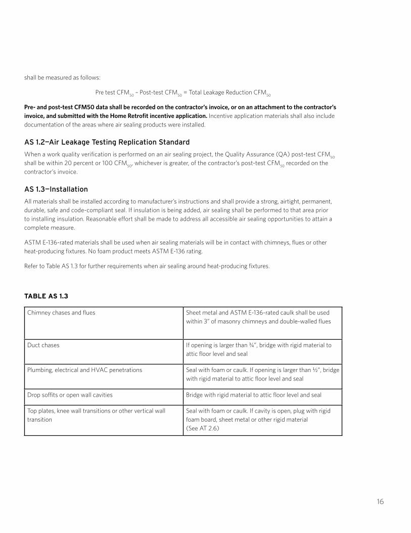
All materials shall be installed according to manufacturer’s instructions and shall provide a strong, airtight, permanent, durable, safe and code-compliant seal. If insulation is being added, air sealing shall be performed to that area prior to installing insulation. Reasonable effort shall be made to address all accessible air sealing opportunities to attain a complete measure.
ASTM E-136-rated materials shall be used when air sealing materials will be in contact with chimneys, flues or other heat-producing fixtures. No foam product meets ASTM E-136 rating.
Refer to Table AS 1.3 for further requirements when air sealing around heat-producing fixtures.
TABLE AS 1.3
Chimney chases and flues Sheet metal and ASTM E-136-rated caulk shall be used within 3” of masonry chimneys and double-walled flues
Duct chases If opening is larger than ¾”, bridge with rigid material to attic floor level and seal
Plumbing, electrical and HVAC penetrations Seal with foam or caulk. If opening is larger than ½”, bridge with rigid material to attic floor level and seal
Drop soffits or open wall cavities Bridge with rigid material to attic floor level and seal
Top plates, knee wall transitions or other vertical wall transition
Seal with foam or caulk. If cavity is open, plug with rigid foam board, sheet metal or other rigid material (See AT 2.6)

17
Knee walls Seal penetrations with foam or caulk
Exhaust fans or ICAT-rated recessed lights Seal fan housing to ceiling with foam or caulk
Accesses Weather-strip access hatch perimeter
Refer to Appendix D for recommendations for air sealing around non-IC rated recessed lights.
AS 1.4—Minimum Ventilation Level, or MVL
The MVL shall be calculated for air sealing to be deemed a complete measure. Sufficient mechanical ventilation shall be installed as part of the air sealing project when the Ventilation Potential is below the MVL (see MV 1.2).
AS 1.5—Exhaust Fans
Refer to AT 1.6 to 1.8 and UN 2.6 to 2.7 for complete requirements for ducting exhaust fans to the exterior of the structure.

18
HOME RETROFIT SPECIFICATIONS MANUAL
AIR SEALING COMPLETE MEASURE CHECKLIST
All work shall meet Energy Trust of Oregon specifications. This checklist serves as a reference guide only. Please refer to the 2018 Specifications Manual for additional information and clarification. Refer to Appendix D for recommended air sealing target areas.
A Blower Door test shall be performed prior to work being installed and again after work is installed to be considered a complete measure. Technicians operating the Blower Door shall adhere to program-specified procedures for diagnostic testing.
Air sealing shall be performed in the following sequence to prioritize energy-savings opportunities:
¨ 1. Between the attic and the conditioned space
¨ 2. Walls between the garage and the house
¨ 3. Floor above a crawlspace, or exterior walls of a conditioned basement
¨ 4. Walls between the conditioned space and the unconditioned space
¨ 5. Other opportunities as identified by Blower Door testing
If the final CFM measurement is below the minimum ventilation level (MVL), mechanical ventilation shall be installed. Refer to the MV section of the manual for further information.
A functioning UL-listed carbon monoxide alarm is required as part of air sealing whenever a combustion appliance is present in the home, an attached garage, or another attached space.
Print Name: Signature: Date:

19
AT—ATTIC INSULATION: OVERVIEW
AT 1.0—Introduction
This section lists work and details that shall be performed before insulation is installed in attics and specifications for how to install insulation and attic-related ventilation. Insulation shall be installed to reduce heat loss between conditioned and unconditioned spaces.
To be considered a complete measure and eligible for incentives, attic insulation shall:
1. Comply with the complete measure guidelines listed in section IN 1.02. Be installed in an area of unconditioned space that is eligible for incentives 3. Bring the connected, accessible unconditioned space into compliance with the applicable requirements listed
in section AT (Refer to Illustrations AT 1.0a through AT 1.0d)
In cases where varying levels of insulation exist in an attic, Appendix A shall be used to determine whether the whole attic area qualifies for incentives. If not, only the area of attic that meets incentive criteria shall be claimed for incentives. Energy Trust does not require that existing insulation in attic areas be increased if the existing insulation level is greater than the incentives qualification criteria.
Blown insulation that is not higher than the top of a 2” x 4” ceiling joist is eligible for Energy Trust incentives.
For purposes of qualifying for attic insulation incentives, Home Retrofit considers batt insulation labeled and rated as R-13 to be R-11. This is the only circumstance where batt insulation shall be considered to have a lower R-Value than its manufacturer rating.
Situations where insulation has been contaminated by vermin shall not be used to de-rate the insulation’s R-Value.
All homeowner self-install projects shall receive Quality Assurance verification before incentives are paid.
Illustrations AT 1.0a through AT 1.0d (next page) provide guidance for installing incentive-eligible attic insulation in a variety of situations.
Refer to IN 1.13 for the Home Retrofit procedure for determining the R-Value of existing insulation.

20
AT 1.0a: A flat attic space over the entire living space. The entire attic area “a” shall be brought into compliance with the requirements of section AT.
AT 1.0b: A rake and crown attic space with vented sloped cavities. The entire attic area “a”—all connected rakes and crown—shall be brought into compliance with the requirements of section AT.
AT 1.0c: A rake and crown attic space with unvented sloped cavities. Only the specific area where attic insulation is being installed— “a,” “b” or “c”—is required to comply with section AT.
AT 1.0d: Two flat attics physically separated from one another. Only the specific area being insulated— “a” or “b” —is required to comply with section AT.
AT 1.1—Attic Air Sealing
Home Retrofit strongly recommends, but does not require, attic air sealing prior to installation of attic insulation. Refer to Appendix D for guidelines.
21
AT 1.2—Passive Attic Ventilation: Sizing and Distribution
Home Retrofit strongly recommends, but does not require, the net free area calculation of attic ventilation prior to installation of attic insulation. Refer to Appendix D for the net fee area calculation and recommendations on total attic venting.
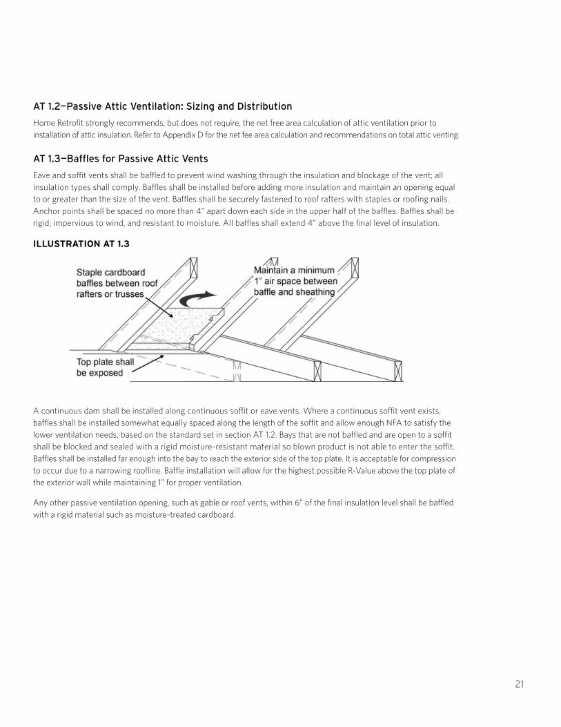
AT 1.3—Baffles for Passive Attic Vents
Eave and soffit vents shall be baffled to prevent wind washing through the insulation and blockage of the vent; all insulation types shall comply. Baffles shall be installed before adding more insulation and maintain an opening equal to or greater than the size of the vent. Baffles shall be securely fastened to roof rafters with staples or roofing nails. Anchor points shall be spaced no more than 4” apart down each side in the upper half of the baffles. Baffles shall be rigid, impervious to wind, and resistant to moisture. All baffles shall extend 4” above the final level of insulation.
ILLUSTRATION AT 1.3
A continuous dam shall be installed along continuous soffit or eave vents. Where a continuous soffit vent exists, baffles shall be installed somewhat equally spaced along the length of the soffit and allow enough NFA to satisfy the lower ventilation needs, based on the standard set in section AT 1.2. Bays that are not baffled and are open to a soffit shall be blocked and sealed with a rigid moisture-resistant material so blown product is not able to enter the soffit. Baffles shall be installed far enough into the bay to reach the exterior side of the top plate. It is acceptable for compression to occur due to a narrowing roofline. Baffle installation will allow for the highest possible R-Value above the top plate of the exterior wall while maintaining 1” for proper ventilation.
Any other passive ventilation opening, such as gable or roof vents, within 6” of the final insulation level shall be baffled with a rigid material such as moisture-treated cardboard.

22
AT 1.4—Dams
Dams shall be installed where final levels of loose-fill insulation differ. Common areas requiring a dam include raised or dropped ceilings, the sides of vaulted ceilings, and between insulated and uninsulated areas such as garages. Dams shall be installed to maintain a consistent R-Value by one of the following methods:
1. A durable, rigid material such as plywood, oriented strand board, moisture-treated cardboard or foam board installed along the full length of required area and extending 4” above the final level of insulation. Rigid dams shall be mechanically and securely fastened.
2. An insulation batt a minimum of 14½” wide with an R-Value equal to or greater than that specified for the attic, laid flat along the full length of the required area. Insulation batts used as a dam shall be installed so that no gaps or voids exist.
Insulation dams as described in AT 1.10 are required around attic accesses and for porch roofs adjacent to the attic above conditioned space.
When mechanical equipment is located in the attic and regular access is needed for maintenance, newly installed insulation shall not prevent or block access. In these cases, a pathway shall be maintained including damming on both sides so access can be gained without disturbing the insulation. See AT 2.3 for additional details on insulating below decked platforms and walkways.
Damming shall be installed around mechanical equipment located in the attic, e.g. an air handler cabinet, where heights of loose-fill insulation change to prevent loose-fill from piling up against the equipment and to provide access for maintenance or replacement.
Refer to AT 1.10 for specifications for damming attic accesses.
Sloughing is not permitted.
ILLUSTRATION AT 1.4
23
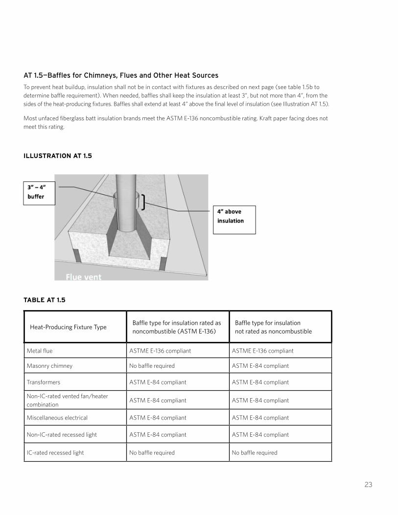
AT 1.5—Baffles for Chimneys, Flues and Other Heat Sources
To prevent heat buildup, insulation shall not be in contact with fixtures as described on next page (see table 1.5b to determine baffle requirement). When needed, baffles shall keep the insulation at least 3”, but not more than 4”, from the sides of the heat-producing fixtures. Baffles shall extend at least 4” above the final level of insulation (see Illustration AT 1.5).
Most unfaced fiberglass batt insulation brands meet the ASTM E-136 noncombustible rating. Kraft paper facing does not meet this rating.
ILLUSTRATION AT 1.5
TABLE AT 1.5
Heat-Producing Fixture TypeBaffle type for insulation rated as noncombustible (ASTM E-136)
Baffle type for insulation not rated as noncombustible
Metal flue ASTME E-136 compliant ASTME E-136 compliant
Masonry chimney No baffle required ASTM E-84 compliant
Transformers ASTM E-84 compliant ASTM E-84 compliant
Non-IC-rated vented fan/heater combination
ASTM E-84 compliant ASTM E-84 compliant
Miscellaneous electrical ASTM E-84 compliant ASTM E-84 compliant
Non-IC-rated recessed light ASTM E-84 compliant ASTM E-84 compliant
IC-rated recessed light No baffle required No baffle required

24
Heat-Producing Fixture TypeBaffle type for insulation rated as noncombustible (ASTM E-136)
Baffle type for insulation not rated as noncombustible
Vented exhaust fans No baffle required No baffle required
Extra-low voltage electrical* No baffle required No baffle required
Modern thermoplastic-insulated electrical wiring
No baffle required No baffle required
*Extra-low voltage is defined as < de 50Vrms AC, or < de 120V DC.
ASTM E-136 compliant baffles are noncombustible and shall be made of rigid material and secured with noncombustible mechanical fasteners. Tape is not a mechanical fastener.
ASTM E-84 compliant baffles are fire-resistant. If necessary, ASTM E-84 compliant baffles shall be secured using fire-resistant fasteners. All ASTM E-84 compliant baffles shall be rigid enough to maintain the required minimum spacing (see Illustration AT 1.5).
AT 1.6—Bath and Exhaust Fans
All exhaust fans shall be vented to the exterior of the structure and secured to the exterior sheathing with no gaps to prevent exhaust air from re-entering the attic (see Illustration AT 1.6). At least one functioning damper shall be present in each system, either at the fan or where vented to the outside. It is highly recommended that exhaust ducts traveling through unconditioned space be insulated to prevent condensation.
Exhaust fans shall be vented to the nearest feasible location. Exhaust ducts shall not sag, shall be as straight as possible to maximize effective airflow, and shall have no more than two 90° turns, or equivalent. Sags, turns, bends and elbows restrict air movement and effective airflow from the exhaust device. If an attic vent is used for fan exhaust, it shall not be included in attic vent area calculations (see section AT 1.2).
Vent ducts shall be securely attached at each joint and to the fan housing using mechanical fasteners, such as screws or mechanically tightened metal clamp-type straps. The exhaust boot assembly shall be securely and mechanically fastened where it vents to the exterior of the structure (see Illustration AT 1.6). Sealing materials such as tape, caulk and foam are not acceptable mechanical fasteners. Mastic, UL-listed metal HVAC tape, or mastic tape may be used to seal gaps in exhaust ducts. Duct tape is not an approved material for sealing or supporting exhaust fan ducts.
Existing flexible plastic or metal vent ducts may remain if they are free of holes and kinks and are in otherwise good condition. Existing plastic or metal ducts shall be vented to the exterior, free of gaps and sealed to prevent exhaust air from re-entering the attic. Exhaust ducting shall be insulated to a minimum of R-4 when required for code compliance.

25
ILLUSTRATION AT 1.6—EXHAUST BOOT CONNECTED TO SHEATHING
AT 1.7—Kitchen Fans
Kitchen exhaust fans shall be vented to the exterior of the structure and secured to the exterior sheathing with no gaps to prevent exhaust air from re-entering the attic. Existing rigid or flexible metal ducts may remain, but existing plastic ducts shall be replaced. Sealing materials such as tape, caulk and foam are not acceptable mechanical fasteners. Mastic, UL-listed metal HVAC tape, or mastic tape may be used to seal gaps in exhaust ducts. Duct tape is not an approved material for sealing or supporting exhaust fan ducts.
If a new exhaust duct is required for a kitchen stove, it shall be at least 28 gauge galvanized steel, stainless steel, copper or aluminum and have a smooth interior surface. The exhaust duct shall be airtight and extend directly into a code-approved metal vent cap.
Vent ducts shall be securely attached at each joint and to the fan housing using mechanical fasteners. The exhaust duct shall meet manufacturer’s requirements and all local building codes. At least one damper shall be functioning in each system, either at the fan or where it vents to the outside. Exhaust ducting shall be insulated to a minimum of R-4 when required for code compliance.
See UN 2.7 for downdraft exhaust fan venting requirements.
AT 1.8—Dryer Exhaust Fans
Dryer exhaust venting that travels through the attic shall comply with AT 1.6. Refer to UN 2.6 for dryer exhaust ventilation specifications.
AT 1.9—Water Pipes in Attics
If water pipes exist in the attic, they shall be insulated to meet specification UN 2.3.
AT 1.10—Interior Attic Access Doors
All operable attic accesses opening to interior spaces shall be insulated, weatherstripped and protected from having

26
loose-fill insulation fall through the opening. Weatherstripping shall be permanently attached to create an effective air seal between the attic access frame and the door. Accesses with air leaks that cannot be weatherstripped shall be repaired or replaced prior to insulating. Weatherstripping shall not prevent easy operation of doors, latches or bolts.
All operable accesses shall remain operable, unless the access is sealed off in favor of another existing or a newly created access. Work performed in an inaccessible area that will remain inaccessible after project completion shall be documented with photographs detailing the project’s compliance with relevant specifications.
Ceiling accesses shall be insulated to R-30 with batt-type or rigid insulation. Knee wall accesses shall be insulated to a minimum of R-15.
Batt-type insulation shall be attached to the door with twine stapled to the edges of the door. Stapling the insulation directly to the door is unacceptable. Rigid insulation may be fastened to the door in lieu of batt-type insulation.
Alternatively, R-5 or greater rigid insulation installed between the access cover and a rigid protective material (OSB, plywood or other durable rigid material) attached over the entire access cover area is permissible. Insulation shall be sealed around the perimeter to the access cover using caulk, adhesive or spray foam. Access-cover assembly shall be tightly sealed using weatherstripping around the entire perimeter.
Attic accesses shall be protected from having loose-fill insulation fall through the opening. The full level of ceiling insulation shall be maintained to the edge of the attic access opening by one of the following methods:
1. The opening may be framed with wood or plywood boards. The framing shall be permanently attached and extend at least 4” above the final level of insulation. Cardboard and foam board are not acceptable materials for attic access damming.
2. An insulation batt a minimum of 14½” wide laid flat, with an R-Value equal to that specified for the attic, may be placed tightly around the perimeter of the access opening. This 14½” width shall be maintained in all outward directions from the access opening, including corners. Insulation batts used as a dam shall be installed so that no gaps or voids exist.
ILLUSTRATION AT 1.10—INTERIOR ATTIC AND KNEE WALL ACCESSES SHALL BE INSULATED AND WEATHERSTRIPPED.

27
AT 1.11—Pull-Down Stairs
Pull-down stairs in conditioned areas shall be weatherstripped and insulated to a minimum of R-10. Insulation and weatherstripping shall not prevent easy operation of the stairs. Factory or site-built pull-down-stair covers, or airtight boxes made of foam board and sealed with caulk or foam, shall have a minimum of R-10.
Factory-built pull-down-stair assemblies with a minimum R-5 insulation rating will be permitted provided the insulation is between conditioned space and the attic stair assembly and air infiltration is prevented by gaskets or weatherstripping. For questions about this specification, email the trade ally coordinator at [email protected] or call 1.866.365.3526 (option 3).
AT 1.12—Exterior Attic Access Doors
Any outside access shall have a door that is easily opened to permit inspection, and shall be weatherproof and vermin-proof.
AT 1.13—Vertical Walls in Attic Spaces
Any vertical wall in an attic that separates conditioned space from unconditioned space shall be sealed for air leaks and shall be insulated to fill the cavity. Insulation shall be secured and covered with a vapor-permeable air barrier. Vertical walls may include side walls of vaults, skylights, transitions in ceiling height or other surfaces. See AT 2.6 for program requirements for knee wall insulation.
In cases where no wall exists between conditioned and unconditioned space, a wall shall be constructed using a rigid, permanent material, air leaks shall be sealed, and insulation shall be installed.
ILLUSTRATION AT 1.13

28
AT—ATTIC INSULATION: INSTALLATION
AT 2.0—General Attic Insulation Requirements
Attic insulation shall be in contact with the conditioned area of the home and shall be installed so there is no air space between the insulation and the conditioned area.
In attics with no existing insulation, vapor retarders, such as kraft facing on fiberglass batts, shall face the conditioned area of the building. New insulation with a vapor retarder shall not be installed on top of existing insulation. Insulation assemblies shall have no more than one vapor retarder, and it shall be in contact with the conditioned surface.
If existing attic insulation has a vapor retarder on its top surface, remove the vapor barrier from the insulation material, replace the insulation material, or reorient the existing insulation so vapor retarders are in contact with the conditioned surface.
If the added attic insulation compresses the existing insulation, the final R-Value shall be R-38 or greater. After installing the insulation, eave and soffit vents shall remain unblocked.
AT 2.1—Installing Loose-Fill Insulation
Loose-fill insulation shall be level and smooth with a uniform R-Value. Installation of loose-fill insulation shall comply with baffling and damming requirements as defined in AT 1.3, 1.4 and 1.5. Toward the eaves, where a sloping roof prevents insulation from being installed to R-38, insulation shall be installed up to the roof decking to maximize R-Value. In soffit-vented assemblies, insulation shall be installed up to the baffles. If new insulation will be blown over existing insulation, the existing insulation shall be in contact with the air barrier.
AT 2.2—Installing Batt-Type Insulation
If batt-type insulation is installed, prepare the attic in the way described for loose-fill insulation. As stated in AT 2.0, do not install vapor retarders over existing insulation. In attic areas where no insulation exists, batts with vapor retarders may be used. The vapor retarder shall be in contact with the ceiling.
Batts shall be cut to fit and placed tightly together with no gaps, except those required for clearance around heat-producing fixtures. Where practical, place one row of batts between the joists and another row of batts
on top of the first row and at right angles to the joists. When lower ventilation exists, baffling is required to ensure effective R-Value and prevent wind washing of insulation. Refer to AT 1.3 for baffling requirements.
When installing foam insulation products, the manufacturer’s name, product identification and information to determine the end use shall be left with the homeowner and presented to a Home Retrofit representative for review during the QA process.
AT 2.3—Floored Attics and Platforms
Cavities below decked storage areas, platforms, and walkways above a conditioned space shall be insulated to the highest practical level. Decked areas shall not be included in the square footage calculation of the insulation incentives when they are insulated to less than R-38 and exceed 5% of the attic area or 64 sq. ft., whichever is greater. When decked areas are less than 5% of the attic area or 64 sq. ft., they may be included in the incentives area calculation. When unusual circumstances allow for only the cavity to be filled, contact Home Retrofit for incentives information.Refer to AT 1.4 for damming requirements for decked areas.

29
Insulation shall be installed under the boards of floored attics. To fill the cavities, the boards can be lifted, or holes no more than 4’ apart can be drilled into them. Joist cavities shall be tightly packed with insulation.
AT 2.4—Vented Vaulted Ceilings
If insulation is added to a vented vaulted ceiling, a 1” air space shall be maintained above the insulation. Each cavity shall have an upper and a lower vent.
AT 2.5—Unvented Vaulted Ceilings
If insulation is added to an unvented vaulted ceiling, it shall be filled with tightly packed insulation.
AT 2.6—Insulating Rake and Crown Attics
When insulating rake and crown attics, a continuous thermal boundary shall be created to be considered a complete measure. Refer to program information sheet PI320I for information about vertical-wall incentives.
If rake attics are considered unconditioned space, knee wall accesses shall be insulated to R-15 and weatherstripped to create an effective air seal. If the rake is used for storage, fibrous knee wall door insulation shall be covered to prevent human contact. Refer to IN 1.9 for further information. Foam-core doors with a minimum R-5 insulation rating (manufactured for exterior use) will be permitted in knee wall door installations, provided gaskets or weatherstripping prevent air infiltration around the entire door perimeter.

30
ILLUSTRATION AT 2.6
Use one of the following methods to treat a rake and crown attic. In all cases, the sloped cavity and crown shall be insulated unless physical barriers exist.
METHOD A
If the upper and lower passive ventilation calculation requires air to move from rake to crown, a 1” air space shall be maintained between the insulation and the roof deck with continuous baffle or equivalent. Knee walls shall be sealed for air leaks and shall be insulated and covered with a vapor-permeable air barrier. Knee walls shall be treated according to this requirement, regardless of existing insulation levels. Cavities where the knee wall reaches the rake floor shall be plugged with an air barrier and sealed using caulk or foam. Rake insulation shall be in contact with plugs. Refer to Illustration AT 2.6.
METHOD B
If rake and crown attic spaces have adequate ventilation independently, the sloped cavity may be completely filled. Loose-fill insulation may be used as long as the lower opening of each cavity is dammed with a rigid, vapor-permeable material to prevent insulation from falling out of the cavity.

31
Knee walls shall be sealed for air leakage, and shall be insulated and covered with a vapor-permeable air barrier, regardless of existing insulation levels. Cavities where the knee wall reaches the rake floor shall be dammed or plugged with an air barrier and sealed using caulk or foam. Rake insulation shall be in contact with plugs.
Refer to Illustration AT 2.6.
AT 2.7—Interior Roof Insulation
Open attic spaces may be treated as conditioned space if air-impermeable insulation is installed. Air-impermeable insulation includes spray foam, rigid foam with appropriate sealants, or other materials as defined by the International Residential Code, or IRC. Insulation shall fill the roof rafter cavity, and all roof framing shall be insulated to a minimum of R-3. If rigid board is used, all seams shall be sealed using foam or caulk. Refer to IN 1.5 for foam insulation requirements.
If insulation is not considered a vapor retarder, then a vapor retarder shall be installed on the conditioned side of the insulation. If the space is intended to be habitable or if there is a combustion appliance in the zone, applicable thermal and ignition barrier requirements shall be met.
AT 2.8—Low-Sloped and Flat Roofs
Building permits and code compliance are the responsibility of the homeowner and contractor. Program preapproval is required for all low-sloped and flat roofs that cannot be insulated to R-38.
EXTERIOR APPLICATIONS
When installing rigid insulation on top of or beneath roof sheathing, the overall insulation assembly shall equal or exceed R-19.
PREPARATION
1. Recessed lights in insulated cavities shall be IC rated or ICAT rated.2. All plumbing vents, kitchen fans, bath fans, wood stoves and other fixtures shall vent to the outside of the
new roof and be adequately flashed and sealed.

32
HOME RETROFIT SPECIFICATIONS MANUAL
ATTIC INSULATION COMPLETE MEASURE CHECKLIST
All work shall meet Energy Trust of Oregon specifications. This checklist serves as a reference guide only. Please refer to the 2018 Specifications Manual for additional information and clarification. Specific reference sections are noted in italics.
¨ Determine if storage or human contact areas are present. IN 1.9
¨ Install baffles at eave vents, heat-producing fixtures, flues and chimneys. AT 1.3 and AT 1.5
¨ Floor above a crawlspace, or exterior walls of a conditioned basement
¨ Walls between the conditioned space and the unconditioned space
¨ Other opportunities as identified by Blower Door testing
¨Dams shall be installed at interior accesses and where insulation is at different levels to keep loose fill from falling out of attic. Dams shall be installed at interior accesses, mechanical equipment, and where insulation is at different levels to keep loose fill contained. AT 1.4 and AT 1.10
¨Interior ceiling accesses shall be insulated to a minimum of R-30 and knee wall access doors shall be insulated to a minimum of R-15. Interior accesses shall have permanent weatherstripping. AT 1.10 and AT 2.6
¨Verify all exhaust fans are vented completely to the exterior with no gaps. AT 1.6–1.8 Washington customers shall insulate all exhaust fan ducts in unconditioned spaces to a minimum of R-4
¨ Insulate water lines in attic space. AT 1.9
¨ Insulate and weatherstrip access panel or pull-down stairs. AT 1.10–1.12
¨ Insulate vertical walls and cover with air barrier. Install blocking in floor under knee wall. AT 2.6
¨ Verify R-Value and condition of installation of insulation. Appendix B
¨ All vapor barriers shall face the living area. AT 2.0
¨ Vertical walls separating attics from indoors shall be insulated. AT 1.13 and AT 2.6
Print Name: Signature: Date:

33
DU—DUCT INSULATION
DU 1.0—Introduction
To be eligible for a Home Retrofit duct insulation incentive, the condition of existing insulation shall be R-2 or less and ducts shall be insulated to R-11 or greater. Flexible ducts shall be R-8 or greater. Basements that contain HVAC ducts or have a direct access to the interior conditioned space of a home shall be considered conditioned space. Insulation installed on ducts in conditioned space is not eligible for Energy Trust incentives.
Energy Trust’s measure eligibility requirement for duct insulation is R-2 or less. This threshold shall be interpreted as 1” of duct insulation or less.
To be considered a complete measure and eligible for incentives, duct insulation shall:
1. Comply with complete measure guidelines listed in section IN 1.02. Comply with carbon monoxide alarm guidelines listed in IN 1.23. Bring all accessible ductwork into compliance with the applicable requirements listed in section DU
All existing ductwork, regardless of insulation level, shall comply with DU 1.1a. Prescriptive duct sealing (DU 1.1d) is required only on ductwork eligible for incentives.
DU 1.1—Duct Sealing and Repair
All ducts in unconditioned space shall be sealed before duct insulation is installed. Ducts may be sealed prescriptively or using performance-based verification. All physically accessible ducts in unconditioned areas shall be sealed.
DU 1.1a—Duct Repair
Inferior sections of duct—such as rusted, crushed or disconnected sections or sections otherwise ineffective—shall be repaired or replaced before duct sealing is performed. When there are large gaps in sheet metal or duct connections, repairs shall be made using sheet metal, sheet metal screws, and/or mastic and mesh-reinforcing tape. Gaps greater than ¹/8" shall be reinforced using mesh-reinforcing tape before applying mastic. Disconnected, loose-fitting or new metal ducts shall be secured using at least three sheet metal screws at each connection.
DU 1.1b—Duct Support
To minimize sagging, ducts shall be supported with durable supports. Flexible ducting supports shall be listed as UL-181 approved, be at least 1½" wide and not restrict airflow. Flexible ducting shall be supported within 3' of each connection to a hard duct. If possible, ducts shall be supported above the ground. When contact with the ground is unavoidable, closed-cell rigid insulation shall be placed under the ducts.
DU 1.1c—Duct-Sealing Materials
Ducts shall be sealed using pliable, water-based mastic labeled as meeting UL-181 standards. Boot-to-floor connections shall be sealed with silicone caulking, pliable mastic or expanding foam. Foil or mastic HVAC tape labeled as meeting UL-181 standards may only be used on the air handler.

34
DU 1.1d—Duct-Sealing Opportunities
All accessible connections of the supply and return plenum and trunkline, and all accessible takeoffs, runs and boots—including the gores on adjustable elbows—shall be sealed with approved materials. The following target areas for prescriptive duct sealing are listed in order of priority:
1. Plenum2. Plenum-to-takeoff connections3. Remove existing loose tape before applying mastic4. Branch Ts, Ys and Ls5. Add three screws to each duct connection6. Duct-to-duct connections 7. Gores on adjustable elbows8. Finger/dovetail joints 9. Boots10. Boot-to-floor, boot-to-wall and boot-to-ceiling connections11. Air-handler cabinet to return and base can
The presence of insulation alone shall not be considered a barrier to accessibility. If continuous R-4 or higher insulation exists and is in good condition, it shall be in the same or better condition upon completion of duct sealing. Refer to DU 1.2 for duct insulation requirements when replacing insulation.
Loose tape shall be removed from rigid ducts prior to sealing. Secured tape shall be completely covered with mastic, which shall extend at least ½” beyond the tape edge on either side and be at least ¹/8” thick.
DU 1.1e—Flexible Ductwork
All flexible ducts shall be joined to a section of rigid duct of matching diameter, including locations where two separate sections of flex duct meet. Both the inner and outer lining shall be tightly fastened using a compression strap tightened with a tool designed for that purpose. Tape may remain as long as a compression strap is installed to maintain a permanent connection. Flexible ducting shall be supported and comply with UL-181 requirements.
DU 1.2—Insulating Ductwork
All ducts in unconditioned areas shall be insulated. Special attention shall be paid to elbows and termination areas to ensure complete coverage. Do not insulate over flex ducts or preformed fiberglass duct board, and remove duct board insulation that is R-2 or less. Insulation shall be secured to ductwork every 12” with rot-proof twine, noncorrosive wire or manufacturer-approved vinyl tape if the insulation is vinyl-backed.
Duct insulation installed in basements, garages, storage areas or other human contact areas shall be covered to limit occupant exposure to insulation fibers (see section IN 1.9). Covering shall meet applicable fire codes.

35
HOME RETROFIT SPECIFICATIONS MANUAL
DUCT INSULATION COMPLETE MEASURE CHECKLIST
All work shall meet Energy Trust of Oregon specifications. This checklist serves as a reference guide only. Refer to the 2018 Specifications Manual for additional information and clarification. Specific reference sections are noted in italics.
A functioning UL-listed carbon monoxide alarm is required as part of duct insulation whenever a combustion appliance is present in the home, an attached garage, or another attached space.
Prescriptive Duct Sealing Target Areas (In Order of Priority) DU 1.1d
¨ 1. Mastic plenum ¨ 7. Mastic gores on adjustable elbows
¨ 2. Mastic plenum-to-takeoff connections ¨ 8. Mastic finger/dovetail joints
¨ 3. Remove existing loose tape before applying mastic ¨ 9. Mastic boots
¨ 4. Mastic branch Ts, Ys and Ls ¨10. Mastic or caulk boot connections to floor/wall/ceiling
¨ 5. Add three screws to each duct connection ¨11. UL-181 tape or caulk air-handler cabinet to return and base can
¨ 6. Mastic duct-to-duct connections
Other Duct Insulation Requirements
Duct Repair: DU 1.1a
¨ Rusted/crushed/disconnected/ineffective duct section repaired/replaced
¨Repaired by sheet metal, sheet metal screws and/or mastic and mesh-reinforcing tape
¨ Mesh-reinforcing tape and mastic used on gaps > ¹/8"
Duct Support: DU 1.1b
¨Mesh-reinforcing tape and mastic used on ¨
Supported above ground (If not possible, closed-cell rigid foam shall be placed under duct)
Flexible Duct: DU 1.1b, DU 1.1e
¨ Supported within 3’ of hard duct connection
¨ Support material at least 1 ½” wide and does not restrict airflow
¨ Support material shall be UL-181 rated
¨ Sections joined to rigid duct of a matching diameter
¨ Inner and outer lining tightly fastened with compression strap
Duct Insulation: DU 1.2
¨Secured to ductwork every 12” with rot-proof twine/noncorrosive wire/manufacturer-approved vinyl tape
Print Name: Signature: Date:

36
MA—MANUFACTURED HOMES: GENERAL SPECIFICATIONS
MA 1.0—Introduction
A manufactured home is a structure, transportable in one or more sections, that is built on a permanent chassis and designed to be used as a dwelling, with or without a permanent foundation, when connected to the required utilities and including the plumbing, heating, air-conditioning and electrical systems contained therein (source: Part 3280, Manufactured Home Construction and Safety Standards, Oct. 1994).
For purposes of this specification, the definition of manufactured homes also includes older homes that were manufactured in factories and hauled over the road to the home site and are regulated by U.S. Department of Housing and Urban Development, or HUD. Please refer to the current program information sheet PI 320F for existing manufactured home incentives.
MA 1.1—Verifying R-Values
If the existing R-Value of the floor cannot be verified, a default R-Value may be used unless an actual value can be observed during weatherization work. Refer to Appendix B.
ILLUSTRATION MA 1.1
MA 1.2—Blowing Underfloor Insulation
PREPARATION
Belly board or belly wrap shall be repaired to prevent insulation from falling from floor cavity. Repair materials shall be stitch stapled to the belly board or otherwise permanently affixed. Plumbing leaks shall be repaired and decayed wood flooring shall be replaced.

37
ILLUSTRATION MA 1.2
MATERIALS
Materials used to patch the belly board shall be breathable, durable and capable of supporting the insulation. Expanding foam or other sealants shall be used to seal accessible floor penetrations.
INSTALLATION
Underfloor cavities shall be insulated either by drilling small holes in the belly board or by drilling through the rim joists perpendicular to the floor joists. If holes are drilled through the belly board, they shall be patched. Holes drilled in the rim joists shall be patched with wooden plugs.
The entire floor cavity shall be packed with insulation to achieve a minimum of R-25 or the highest practical R-Value.
MA 1.3—Ventilation
Crawlspaces shall be ventilated by openings in exterior foundation walls. Such openings shall have a net area of at least 1 sq. ft. for each 150 sq. ft. of underfloor area. Where moisture is not considered excessive due to climate and groundwater conditions, and if the underfloor ground surface area is covered with an approved ground cover, Home Retrofit may allow operable louvers and may allow the required net area of the vent opening to be reduced to 1/300 or less (minimum 1/1,500).

38
ILLUSTRATION MA 1.3
Openings shall be located as close to corners as practical and shall provide cross ventilation. The required area of such openings shall be distributed equally along the length of at least two opposite sides. Vents shall be covered with corrosion-resistant wire mesh, with mesh openings no greater than ¼” in dimension. Existing vent openings covered with wire mesh do not need to be modified.
Contractors may approve mechanical ventilation when passive ventilation methods are not practical.
If crawlspace ventilation cannot be accomplished in accordance with these requirements, underfloor insulation shall not be installed.
MA 1.4—Ground Covers
If an existing ground cover does not meet Home Retrofit specifications, it shall be repaired, or a new ground cover shall be installed. New ground covers shall be a minimum of six-mil black polyethylene. All joints shall be lapped at least 12”. The cover shall be continuous throughout the crawlspace and there shall be no rips, tears or gaps. Refer to UN 1.3 for complete ground cover specifications.
MA 1.5—Installing Batt-Type Insulation in Underfloor
Refer to Section UN of this manual for underfloor specifications. Once the belly board is removed, the techniques used to insulate a manufactured home underfloor are the same as for site-built homes.
Note: Home Retrofit does not provide incentives for the cost of removing or replacing an existing belly board. State or local code may require belly boards on manufactured homes.
MA 1.6—Replacement Windows
Window requirements for manufactured homes are the same as for site-built homes (see Section WI).
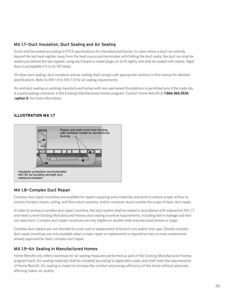
39
MA 1.7—Duct Insulation, Duct Sealing and Air Sealing
Ducts shall be sealed according to PTCS specifications for manufactured homes. In cases where a duct run extends beyond the last heat register away from the heat source and terminates with folding the duct metal, the duct run shall be sealed just behind the last register, using duct board or metal plugs cut to fit tightly and shall be sealed with mastic. Rigid foam is acceptable if it is UL-181 listed.
All other duct sealing, duct insulation and air sealing shall comply with appropriate sections in this manual for detailed specifications. Refer to MA 1.9 to MA 1.13 for air sealing requirements.
Air and duct sealing on existing manufactured homes with non-permanent foundations is permitted only if the trade ally is a participating contractor in the Existing Manufactured Homes program. Contact Home Retrofit at 1.866.365.3526 (option 3) for more information.
ILLUSTRATION MA 1.7
MA 1.8—Complex Duct Repair
Complex duct repair incentives are available for repairs requiring extra materials and work to restore proper airflow to exterior furnace closets, ceiling, and floor return systems, and/or crossover ducts outside the scope of basic duct repair.
In order to receive a complex duct repair incentive, the duct system shall be sealed in accordance with subsection MA 1.7 and meet current Existing Manufactured Homes duct sealing incentive requirements, including test-in leakage and test-out reductions. Complex duct repair incentives are only eligible on double-wide manufactured homes or larger.
Complex duct repairs are not intended to cover cost or replacement of branch runs and/or end caps. Double complex duct repair incentives are only available when a major repair or replacement is required on two or more components already approved for basic complex duct repair.
MA 1.9—Air Sealing in Manufactured Homes
Home Retrofit only offers incentives for air sealing measures performed as part of the Existing Manufactured Homes program track. Air sealing materials shall be installed according to applicable codes and shall meet the requirements of Home Retrofit. Air sealing is meant to increase the comfort and energy efficiency of the home without adversely affecting indoor air quality.

40
To be considered a complete measure and eligible for incentives, air sealing shall:
1. Comply with complete measure guidelines listed in section IN 1.02. Comply with carbon monoxide alarm guidelines listed in IN 1.23. Have a Blower Door test performed before and after air sealing4. Meet the applicable requirements listed in Sections MA and MV
A house sealed below the Home Retrofit minimum ventilation level (MVL) requires mechanical ventilation, as described in Section MV of this manual. The contractor shall provide the homeowner and occupant with Energy Trust’s MVL letter if an air leakage test determines the home is at or below MVL standards. Refer to Appendix D for air sealing guidance when proposed measures might bring the house below the MVL.
MA 1.10—Air Leakage Measurement
An air leakage test using diagnostic equipment to depressurize the conditioned space of the home shall be performed prior to work, and again after work is complete, to be eligible for air sealing incentives. Testing shall be performed only by technicians certified by PTCS, BPI, Residential Energy Analyst Program (REAP) or Performance Air Testing and Sealing (PATS).
A Blower Door and manometer shall be used to perform the air leakage test, with the house set up in the following condition:
1. Open all register dampers2. Close all exterior windows and doors, including overhead garage doors3. Open all interior doors4. Close fireplace or wood stove dampers and doors5. Turn off all exhaust devices6. Turn down combustion water heaters (i.e., set to pilot)7. Set all HVAC system controls to “off”8. Set all ventilation controls to “off”
The air leakage test shall be performed before air sealing (pre-test) and after air sealing (post-test). Reductions in leakage shall be measured as follows:
Pre-Test CFM50 – Post-Test CFM50 = Total Leakage Reduction CFM50
Pre- and post-test CFM50 data shall be recorded on the contractor’s invoice, or on an attachment to the contractor’s invoice, and submitted with the Home Retrofit incentive application. Incentive application materials shall also include documentation of the areas where air sealing products were installed.
MA 1.11—Air Leakage Testing Replication Standard
When a Work Quality Verification is performed on an air sealing project, the Quality Assurance (QA) post-test CFM50 shall be within 20 percent or 100 CFM50, whichever is greater, of the contractor’s post-test CFM50 recorded on the contractor’s invoice.
MA 1.12—Air Sealing Materials and Installation
All materials shall be installed according to the manufacturer’s instructions and shall provide a strong, airtight, permanent, durable, safe and code-compliant seal. If insulation is being added, the area shall be air sealed before installation. Reasonable effort shall be made to address all accessible air sealing opportunities to attain a complete measure.

41
Materials rated ASTM E-136 shall be used when air sealing materials will be in contact with chimneys, flues or other heat-producing fixtures. No foam product meets ASTM E-136 rating.
Refer to Appendix D for recommendations for air sealing around non-IC rated recessed lights.
MA 1.13—Minimum Ventilation Level, or MVL
The MVL shall be calculated for air sealing to be deemed a complete measure. Sufficient mechanical ventilation shall be installed as part of the air sealing project when the ventilation potential is below the MVL (see MV 1.2). Mechanical ventilation shall comply with Section MV in this manual when air sealing is installed in an existing manufactured home.
MA—MANUFACTURED HOMES: COMBUSTION SAFETY PROTOCOLS
MA 2.0—Overview
Sections MA 2.0 through MA 2.10 list requirements for projects within Home Retrofit’s Existing Manufactured Homes service.
Manufactured homes built before HUD standards were enacted in 1976 are not guaranteed to have combustion appliances that adhere to HUD standards for combustion safety. Take extra precaution when servicing manufactured homes with gas furnaces or water heaters made before 1976.
In order for gas-heated manufactured homes to qualify for duct sealing or air sealing through the Existing Manufactured Homes service, the primary heating system must be a sealed combustion furnace. Manufactured homes constructed after 1976 that use a non-HUD approved open combustion gas furnace are ineligible for duct sealing or air sealing. Manufactured homes with gas water heating appliances are eligible for duct sealing and air sealing through the Existing Manufactured Homes service regardless of whether their water heater is sealed combustion or open combustion.
MA 2.1—Combustion Appliance Safety Guidelines
Air sealing can alter the performance of combustion appliances by reducing the amount of available combustion air and can create zones of increased negative pressure. A combustion appliance zone (CAZ) is a conditioned space or enclosed area containing a combustion appliance for the purpose of space heating or water heating. Air sealing can cause increased concentrations of pollutants within the dwelling due to reduced natural air exchanges in the CAZ.
It is the responsibility of the Trade Ally to ensure that all combustion appliances contained within the confines of the structure are properly and safely vented, operating, and have suitable combustion air before and after air and duct sealing occurs and to ensure that all applicable state/local laws, codes, and standards are met and the indoor air quality of the dwelling is not compromised.
Homes with unvented combustion heating appliances are not eligible for air sealing incentives.
A combustion appliance zone (CAZ) is an enclosed area containing a combustion appliance for the purpose of space heating or water heating.
Home Retrofit strongly recommends following combustion appliance zone (CAZ) testing procedures and requirements outlined by industry recognized organizations including, but not limited to, Building Performance Institute, RESNET, or ACCA.

42
MA 2.2—Carbon Monoxide Alarms
When combustion appliances are located within the conditioned space, a functioning UL-listed or equivalent carbon monoxide alarm shall be present or properly installed, regardless of whether the home is eligible for air sealing or duct sealing. All CO alarms shall be installed according to manufacturer specifications.
MA 2.3—Depressurization Standards
The depressurization limit for HUD-approved sealed combustion gas furnaces shall be minus 10 pascals. Net depressurization shall not be lower than minus 10 pascals for gas furnaces and shall not be lower than minus 3 pascals for all other combustion appliances. Combustion appliances include, but are not limited to, gas/propane water heaters, gas/propane/wood stoves (sealed and/or not sealed combustion) and wood/gas/propane fireplaces (sealed and/or not sealed combustion).
MA 2.4—Unvented Combustion Heating Appliance Guidelines
If an unvented combustion heating appliance is present, air sealing and duct sealing shall not be performed. If unvented zonal heating combustion appliances (space heaters) are present, the occupant will be educated on the potential hazards of combustion byproducts associated with such devices.
MA 2.5—Gas Cooking Appliance Guidelines
A CAZ test is not required for gas cooking ranges, gas ovens and/or gas clothes dryers. An unvented gas cooking appliance shall not be considered an unvented combustion appliance. Homes containing gas cooking ranges and/or ovens may qualify for the Existing Manufactured Homes free duct sealing/air sealing service as long as the home meets all other program eligibility criteria.
MA 2.6—Furnace Flue Assessment Guidelines
The combustion flues of any existing gas furnaces shall be visually inspected. HUD-approved manufactured home gas furnaces are direct-vented, sealed combustion units that require an outdoor source of combustion air. The three most common designs for manufactured home gas furnaces are:
1. Furnaces that draw combustion air from the roof through a concentric space in a double-walled chimney2. Furnaces that draw from a duct connected directly to the crawlspace3. Furnaces that draw from both a double-walled chimney and the crawlspace
For gas furnaces that draw combustion air from the roof, the chimney shall be vertical and the chimney cap shall be completely intact and upright.
For gas furnaces that draw combustion air through a duct connected to the crawlspace, this duct shall be visually inspected from underneath the home to ensure that the combustion air source is not blocked or restricted. If a visual inspection fails, the home is not eligible for service until the cause of inspection failure is corrected.
MA 2.7—Gas Water Heater Guidelines
HUD-approved gas water heaters for manufactured homes include both sealed-combustion and open-combustion designs. Gas water heaters shall be visually inspected for flame rollout.
Open-combustion water heaters draw make-up air through a vent commonly found in the floor of the water heater closet. This vent shall be visually inspected to ensure that is unobstructed.

43
Sealed combustion water heaters shall be visually inspected to verify that the combustion air inlet entering from the crawlspace is unobstructed.
If an obstruction is identified, the obstruction shall be removed before performing air sealing or duct sealing. HUD-approved sealed combustion gas water heaters shall not be inspected for flame rollout. If a visual inspection fails, the home is not eligible for service until the situation is remedied.
MA 2.8—Flue Sealant Guidelines
Spray foam shall not be applied to any heat-producing flue under any circumstances.
MA 2.9—Combustion Air Inlet Guidelines
Combustion air inlets shall not be covered, obstructed or sealed under any circumstances.
MA 2.10—Belly or Ceiling Return Duct Guidelines
Gas-heated manufactured homes with a belly return or ceiling return system are not eligible for duct sealing or air sealing.
MV—MECHANICAL VENTILATION
MV 1.0—Introduction
All weatherization upgrades have the potential to affect the indoor air quality and overall tightness of a home. Savings Within Reach and Existing Manufactured Homes projects shall comply with the mechanical ventilation calculation defined in Section MV. Home Performance with ENERGY STAR projects shall adhere to the mechanical ventilation calculations described in Building Performance Institute standards unless otherwise specified by the Home Retrofit program.
MV 1.1—Measurement
An air leakage test using diagnostic testing equipment, such as a Blower Door and manometer, shall be used to measure the overall tightness of a home. Building airflow shall be measured in cubic feet per minute at minus 50 pascals of pressure (CFM50).
MV 1.2—Calculating MVL
When applying for an air sealing incentive, the MVL of a house shall be calculated based on 1) the known number of occupants; 2) an estimate of the possible number of occupants based on the number of bedrooms; or 3) the conditioned volume of the house. Basements that contain HVAC ducts or have a direct access to the interior conditioned space of a home shall be considered conditioned space and shall be considered in volume calculations.

44
The equation resulting in the highest CFM shall be compared to the ventilation potential.
TABLE MV 1.2 CALCULATIONS
1. MVL based on known occupancy MNV = ((# of occupants) x (15 CFM)
2. MVL based on number of bedrooms: MNV = ((# of bedrooms + 1) x (15 CFM)
3. MVL based on volume: MNV = 0.35 ACHnatural x (building volume of conditioned space (ft³))
60 minutes
Each calculation yields an estimate of the required ventilation (in CFMnatural, or CFMn) to maintain good indoor air quality. Identify which is the most restrictive target and then compare it with the ventilation potential.
The following formula is used to convert the measured CFM50 from the Blower Door test to an estimate of the average ventilation potential (in CFM50).
Ventilation potential = CFM50/N
Where N is a correlation factor: N = C x H x S
C = Climate factor (a function of annual temperature and wind). C = 20 is an appropriate approximation for most areas in the Northwest.
H = Height-correction factor
Number of Stories 1 1.5 2 3
Correction Factor (H) 1 0.9 0.8 0.7
S = Wind-shielding correction
Wind Exposure Well Shielded Normal Exposed
Correction Factor (S) 1.2 1 0.9
As long as the measured ventilation potential is greater than the MVL, additional air sealing is possible without creating moisture and indoor air quality problems. If the MVL is greater than the ventilation potential, a mechanical ventilation strategy shall be installed to make up the difference (in CFMn).
Limitations: The CFM50 of a house is a measure of the effective leakage area. The estimate of the amount of ventilation a given leakage area will provide is affected by many factors and is an approximation averaged over a wide range of conditions for the entire year. Periods of over- and under-ventilation will certainly occur.
A properly sized and controlled mechanical ventilation system installed in a tight house envelope is the preferred alternative to ensure adequate ventilation rates at all times.

45
MV 1.3—Non-Heat Recovery Systems
A bathroom fan used for whole-house ventilation shall have automatic and manual controls. Automatic controls shall include a time clock or programmable timer with a minimum of two “on” periods per day. Manual controls shall include a switch, crank timer or dehumidistat to let the occupant turn the fan on and off for spot ventilation purposes. The timer shall be set to provide adequate mechanical ventilation—determined by the MVL—based on the measured flow rate of the fan. The ventilation fan shall be wired to both the manual spot-ventilation switch in the bathroom and to a time clock or timer. New surface-mounted fans shall have a sone rating of 1.5 or less. Existing fans that meet the minimum airflow rates are exempt from the sone rating requirement.
Fans shall be rated for continuous operation by the manufacturer in situations where continuous operation is required.
MV 1.4—Balanced Mechanical Ventilation
Balanced-flow mechanical ventilation systems shall have fans capable of providing the intake and exhaust airflow rates determined in MV 1.2 and provide complete isolation of the intake and exhaust air.
UN—UNDERFLOOR INSULATION: OVERVIEW
UN 1.0—Introduction
Home Retrofit underfloor weatherization measures include adding insulation, sealing floor penetrations, adding ventilation, installing a ground cover and adding water pipe insulation. Insulation shall be installed to reduce heat loss between conditioned space and unconditioned space or to the outside of the house. Basements that contain HVAC ducts or have a direct access to the interior conditioned space of a home shall be considered conditioned space. Insulation installed between a conditioned basement and conditioned space of the home is not eligible for Energy Trust incentives.
To be considered a complete measure and eligible for incentives, floor insulation shall:
1. Comply with the complete measure guidelines listed in section IN 1.02. Be installed in an area of unconditioned space with an existing R-Value of R-0 3. Bring the connected accessible unconditioned space into compliance with the applicable requirements listed
in Section UN (Refer to Illustrations UN 1.0a through UN 1.0d)
Energy Trust requires that a floor have an R-Value of R-0 to be eligible for incentives. R-0 means there is no insulation material in place in the floor assembly. Only the area of the floor with R-0 is eligible for floor insulation incentives. Energy Trust does not require that areas with existing floor insulation receive additional insulation or support techniques.
In both vented and unvented crawlspaces, the floor shall be considered R-0 when there is a foil barrier and no underfloor insulation, or when there is minimal perimeter insulation (less than R-4) and no underfloor insulation.
Situations where insulation has been contaminated by vermin shall not be used for de-rating insulation R-Value.
Replacement of flood-damaged insulation is not eligible for Energy Trust incentives.
Insulation installed on the exterior walls of a crawlspace or on the foundation walls of a basement is not eligible for Energy Trust incentives.

46
Floors on which homeowners are performing an insulation self-install shall have an existing R-Value of R-11 or less. All homeowner self-install projects shall receive Quality Assurance verification before incentives are paid.
Insulation shall be installed so there is no air space between the insulation and the floor. Insulation that is not in continuous contact with the bottom of the subfloor is not eligible for Energy Trust incentives.
Refer to IN 1.13 for the Home Retrofit procedure for determining the R-Value of existing insulation.
Illustrations UN 1.0a through UN 1.0d provide guidance for installing incentive-eligible floor insulation in a variety of situations:
UN 1.0a: An unconditioned crawlspace under the entire living space. The entire crawlspace area “a” shall be brought into compliance with the requirements of Section UN.
UN 1.0b: A full conditioned basement. Conditioned basements are ineligible for floor insulation incentives, although rim joist insulation may be eligible for wall insulation incentives. Refer to UN 2.8 and 2.9.

47
UN 1.0c: Two unconditioned crawlspaces physically separated from one another. Only the specific area where floor insulation is being installed—“a” or “b”—is required to comply with Section UN.
UN 1.0d: A cantilever (or overhang). Only area “a” is required to comply with Section UN.
UN 1.1—Underfloor Preparation and Debris
Degradable and absorbent scrap materials, especially wood and cardboard, shall be removed from the crawlspace. The underfloor shall be checked for water leaks and wood decay before and after work occurs. The homeowner shall be notified and corrective measures shall be taken, when necessary.
UN 1.2—Ventilation
Crawlspaces shall be ventilated by openings in exterior foundation walls. Such openings shall have a net area of at least 1 sq. ft. for each 150 sq. ft. of underfloor area. Where moisture due to climate and groundwater conditions is not considered excessive, Home Retrofit may allow operable louvers and the required net area of the vent opening to be reduced to 1/300 or less (minimum 1/1,500), provided the underfloor ground surface area is covered with an approved ground cover. Vent openings shall be reasonably secure to prevent the entry of vermin or other animals.
Openings shall be located as close to corners as practical and shall provide cross ventilation. The required area of such openings shall be equally distributed along the length of at least two opposite sides. Vents shall be covered with corrosion-resistant wire mesh, with mesh openings not to exceed ¼” in dimension. Existing
vent openings covered with wire mesh need not be modified, except when modification is necessary to prevent the entry of vermin or other animals.
Crawlspace ventilation shall not be blocked by insulation or other material. Baffles shall be installed around ventilation that has been blocked to ensure proper airflow. Where venting cannot be reasonably added except by breaching a foundation, ventilation requirements shall be waived.
UN 1.3—Ground Covers
All crawlspaces require a ground cover. All ground covers shall be a minimum of six-mil black polyethylene. If an existing ground cover does not meet Home Retrofit specifications, it shall be repaired, or a new ground cover shall be installed. All seams shall be lapped at least 12”. The cover shall be continuous, with no rips, tears or gaps. Exposed soil or earth in a basement shall comply. Crawlspaces with a concrete floor, commonly referred to as a “rat slab,” do not require a ground cover as long as the concrete is continuous and in good condition.
UN 1.4—Sealing Floor Penetrations
To prevent transmission of water vapor and to support the effective R-Value of the underfloor insulation, all floor penetrations shall be sealed, including plumbing, wiring and duct penetrations, floor transitions, and similar openings in the air barrier of the underfloor. Caulk, foam or other compatible sealants shall be used.
Open chases around chimneys that extend into the crawlspace shall be sealed using fire-rated materials. Spans greater than ¾” shall be bridged using sheet metal and ASTM E-136 rated caulk within 3” of masonry chimneys and flues.
Bathtub/shower drain accesses shall be sealed. If the drain trap is above the level of the floor, provisions to maintain accessibility for maintenance shall occur.

48
ILLUSTRATION UN 1.4
UN 1.5—Floors Above Other Unconditioned Areas
If the ceiling of a garage, service area, storage area or other unconditioned space (not including basements) serves as the floor of a conditioned space above, this ceiling may be insulated to obtain a Home Retrofit floor insulation incentive. Existing conditions shall comply with current program standards for floor insulation, and the measure shall meet all the relevant requirements in Section UN.
UN 1.6—Rim Joist Insulation
In conditioned basements, the sill plate and each joist bay shall be sealed for air leaks before installing insulation. Gaps between the sill plate and foundation wall shall also be sealed for air leaks. Batt-type or foam insulation used in this application shall be tightly installed, securely fastened, and at least R-15, and shall comply with applicable state and local jurisdictional codes. A human contact barrier shall be installed over batt-type insulation. Foam insulation used to insulate rim joists shall comply with applicable requirements in Section IN 1.5. Incentives will not be paid for rim joist insulation installed in crawlspaces. All reasonably accessible rim joist surfaces shall be insulated to be considered a complete measure.

49
UN—UNDERFLOOR INSULATION: INSTALLATION
UN 2.0—General Installation Requirements
Floor insulation shall be in contact with the floor. Compression of fiberglass batt-type insulation is permitted to assure continuous contact between the insulation and the subfloor. Use of unfaced batt-type insulation is acceptable. There shall only be one vapor retarder in the assembly, and it shall be in direct contact with the subfloor and face the conditioned space of the home.
Kraft facing, commonly attached to batt-type insulation, is a vapor retarder. If kraft facing is attached, it shall be in contact with the conditioned floor of the home.
Compression of insulation is acceptable to maintain continuous contact with the bottom of the floor. Insulation shall be in continuous contact with the floor and fill the entire cavity depth, from the bottom of the subfloor to the bottom of the joist or beam. Insulation shall also be in contact with the joists that frame the cavity. The batt insulation installed into joist cavities shall be slightly wider than the cavity in order to fill the cavity and fit the insulation more securely in place.
Table UN 2.0 lists the size of insulation batt that shall be installed based on the depth of the subfloor cavity. It is not necessary for installed insulation to exceed R-30 when cavity depth is greater than 10”. Insulation installed into a joist cavity taller than 10” shall maintain continuous contact with the floor and meet all other relevant specifications outlined in Section UN.
TABLE UN 2.0
Common Joist Cavity Dimensions Minimum R-Value for Installed Batt Insulation
2x6 R-21
2x8 R-25
2x10 R-30

50
ILLUSTRATION UN 2.0A
Insulation shall be pulled free from any temporary stapling. Insulation shall be cut to fit without gaps or overlaps. There shall be no gaps at the perimeter of the foundation.
ILLUSTRATION UN 2.0B
Insulation shall be supported so it does not block or restrict crawlspace ventilation. If necessary, insulation may be compressed to meet this requirement.

51
UN 2.1—Floor Insulation Support Materials
Use one of the following materials to support floor insulation:
Wood lath—Wood lath shall be a minimum of ¼” x 1”
Twine—Twine shall be non-stretching polypropylene or polyester
Wire—Wire shall be stainless steel, copper or an equivalent material of similar corrosion resistance, with a minimum diameter of 0.04” (size 18 AWG). Self-supporting wire hangers are not acceptable.
Hand stapling is not a durable fastening technique and will not qualify a project for an Energy Trust incentive.
Fasteners for lath, twine or wire may be one of the following: hot-dipped galvanized nails, screws or corrosion-resistant staples that are at least 18 gauge and long enough to penetrate wood at least 5/8”.
ILLUSTRATION UN 2.1
UN 2.2—Spacing Requirements for Support Systems
Staples shall be driven with a power-actuated stapler to achieve at least 5/8” penetration. The maximum spacing for support systems is as follows:
TABLE UN 2.2
Spans Maximum Spacing
24” or less 18” apart
48” 12” apart
60” 8” apart
72” 6” apart

52
Wood lath shall not be used for spans greater than 48". Splicing does not meet this requirement. Wood with a thicker dimension may be used for wider spans.
Support systems for spans greater than 72" or support systems not secured to the bottom of the joists require prior approval by Home Retrofit.
Batt-type insulation shall be supported no more than 3" from the ends. This support shall be parallel to the end of the batt. Small pieces of insulation shall be supported.
ILLUSTRATION UN 2.2
Insulation shall be supported so that it is in direct contact with the bottom of the subfloor sheathing.
Support systems shall be fastened to the underside of floor joists. Joists may be skipped; however, the maximum spacing shall not exceed 12". The maximum span of skipped joists shall not exceed 48".
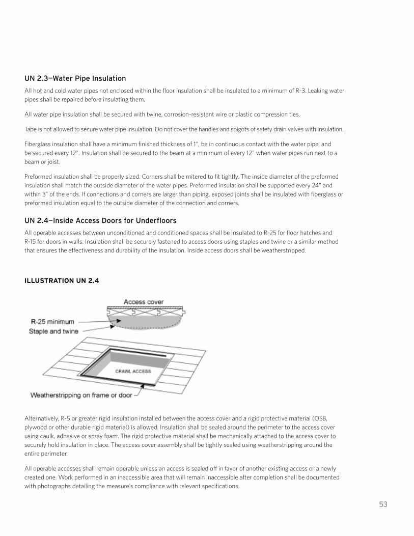
53
UN 2.3—Water Pipe Insulation
All hot and cold water pipes not enclosed within the floor insulation shall be insulated to a minimum of R-3. Leaking water pipes shall be repaired before insulating them.
All water pipe insulation shall be secured with twine, corrosion-resistant wire or plastic compression ties.
Tape is not allowed to secure water pipe insulation. Do not cover the handles and spigots of safety drain valves with insulation.
Fiberglass insulation shall have a minimum finished thickness of 1”, be in continuous contact with the water pipe, and be secured every 12”. Insulation shall be secured to the beam at a minimum of every 12” when water pipes run next to a beam or joist.
Preformed insulation shall be properly sized. Corners shall be mitered to fit tightly. The inside diameter of the preformed insulation shall match the outside diameter of the water pipes. Preformed insulation shall be supported every 24” and within 3” of the ends. If connections and corners are larger than piping, exposed joints shall be insulated with fiberglass or preformed insulation equal to the outside diameter of the connection and corners.
UN 2.4—Inside Access Doors for Underfloors
All operable accesses between unconditioned and conditioned spaces shall be insulated to R-25 for floor hatches and R-15 for doors in walls. Insulation shall be securely fastened to access doors using staples and twine or a similar method that ensures the effectiveness and durability of the insulation. Inside access doors shall be weatherstripped.
ILLUSTRATION UN 2.4
Alternatively, R-5 or greater rigid insulation installed between the access cover and a rigid protective material (OSB, plywood or other durable rigid material) is allowed. Insulation shall be sealed around the perimeter to the access cover using caulk, adhesive or spray foam. The rigid protective material shall be mechanically attached to the access cover to securely hold insulation in place. The access cover assembly shall be tightly sealed using weatherstripping around the entire perimeter.
All operable accesses shall remain operable unless an access is sealed off in favor of another existing access or a newly created one. Work performed in an inaccessible area that will remain inaccessible after completion shall be documented with photographs detailing the measure’s compliance with relevant specifications.

54
UN 2.5—Outside Access Doors for Underfloors
Any outside access shall have a door that is easily opened to permit inspection and shall be weather- and vermin-resistant. A vertical access may be screened when it is part of the crawlspace ventilation system. Horizontal hatch covers shall shed water. Wood in contact with soil or concrete shall be pressure treated.
Existing covers are acceptable if they are in good condition and are weather- and vermin-resistant.
UN 2.6—Dryer Exhaust
Dryer exhaust ducts shall be vented to the exterior of the structure, be sealed to prevent exhaust air from entering the building, have a damper, and terminate in a code-approved vent cap. New dryer ducts shall be rigid metal, securely connected with mechanical fasteners and permanently supported. Exhaust systems shall comply with local code and manufacturer specifications, be as straight as practical, and not exceed 25’. To prevent blockage with lint, dryer vent ducts shall not be connected with screws. A metal clamp or UL-rated foil tape may be used to secure dryer duct connections.
UN 2.7—Downdraft Exhaust Ducts
Downdraft exhaust ducts may have a 90° turn and shall exit through the foundation or exterior wall, be sealed (with no visible gaps) to prevent exhaust air from entering back into the building, and end in a code-approved vent cap.
UN 2.8—Vertical Walls in Underfloor Spaces
Uninsulated walls between conditioned and unconditioned spaces in the underfloor area shall be sealed for air leaks, insulated to a minimum of R-15 and create a continuous thermal envelope. The floor cavities between joists that connect adjacent conditioned space to unconditioned space shall be sealed with a rigid air barrier. When no wall exists, one that extends to the bottom of the subfloor shall be constructed and an effective pressure and thermal boundary shall be installed. See program information sheet PI320I for vertical wall incentives.
UN 2.9—Rim Joist Insulation (optional measure)
In conditioned basements, insulation installed in direct contact with the wooden perimeter band or rim joist may be eligible for the wall insulation incentive. The sill plate and each joist bay shall be sealed for air leaks before insulation installation. Batt-type or foam insulation used in this application shall be tightly installed, securely fastened, and at least R-15, and shall comply with state and local codes. A human contact barrier shall be installed over batt-type insulation. Incentives will not be paid for rim joist insulation installed in crawlspaces. Underfloor insulation shall be installed in homes with crawlspaces.
UN 2.10—Installing Foam Insulation
Spray foam insulation may be used for insulating and air sealing an underfloor area either on its own or in combination with other insulation types (such as flash and batt). This assembly shall meet the requirements for R-Value, be in contact with the conditioned surface, comply with manufacturer specifications, and comply with the thermal and ignition barrier requirements for foam plastics as defined by the prevailing jurisdictional building code. There shall be no gaps or voids in the insulation assembly and all other applicable underfloor specifications shall be met.
Spray foam is exempt from support requirements. When used in combination with other insulation types, spray foam shall be installed in contact with the conditioned surface of the home.
When installing foam-insulation products, the manufacturer’s name, product identification and information to determine the end use shall be left with the homeowner and presented to a Home Retrofit representative for review during the QA process. Refer to IN 1.5 for further requirements for foam insulation.

55
UN 2.11—Miscellaneous Underfloor Specifications
Underfloor areas that allow easy human access shall comply with the requirements defined in IN 1.9 to protect occupants from encountering fibrous insulation in areas where routine storage or maintenance occurs.
An air barrier or skirting shall protect underfloor insulation exposed to the wind, including unskirted crawlspaces and cantilever floors.
Unconditioned unvented basements with concrete floors and walls do not require a ground cover, foundation vents or water pipe insulation, except for pipes located on exterior walls. Unconditioned vented basements with concrete floors and walls do not require a ground cover, but water pipes shall be insulated according to UN 2.3.
Basements with exposed soil or earth shall have a ground cover installed on exposed areas.
If standing water is found in the crawlspace, it must be drained before the floor can be insulated. A sump pump may be needed for some situations. Draining the water is the responsibility of the homeowner.
Before installing insulation in contact with active knob and tube wiring, the electrical system shall be inspected and the homeowner shall receive written approval by a licensed electrician. Insulating floors with knob and tube wiring shall be at the discretion of the contractor and homeowner and adhere to state and local code.

56
HOME RETROFIT SPECIFICATIONS MANUAL
FLOOR INSULATION COMPLETE MEASURE CHECKLIST
All work shall meet Energy Trust of Oregon specifications. This checklist serves as a reference guide only. Please refer to the 2018 Specifications Manual for additional information and clarification. Specific reference sections are noted in italics.
¨ Determine the intended conditioned spaces and location of air and thermal boundaries. UN 1.0
¨ Remove debris from crawlspace. UN 1.1
¨ Determine if storage or human contact areas are present. IN 1.9
¨ Verify adequate passive ventilation. UN 1.2
¨ Seal all floor penetrations (plumbing, wiring, duct penetrations and floor transitions). UN 1.4
¨ Ensure ground cover is complete, continuous and properly lapped. UN 1.3
¨Insulation being installed is an appropriate R-Value and is properly supported using approved materials and fasteners. Supports are spaced according to the span. UN 2.0–2.2 and Appendix B
¨ Entire length of insulation is in contact with the floor. UN 2.0
¨ All vapor barriers face the living area. UN 2.0
¨ Insulate water lines. UN 2.3
¨ Access doors are insulated to R-25 and weatherstripped. UN 2.4
¨ Verify access doors open easily and are weatherproof and vermin-proof. UN 2.5
¨ Crawlspace walls between living area and crawlspace areas are insulated to R-15. UN 2.8
¨ Exhaust ducts vent completely to the outside with no gaps. UN 2.6 and UN 2.7
¨ Vertical walls separating crawlspaces from indoors are insulated. UN 2.8
Print Name: Signature: Date:

57
WA—WALL INSULATION
WA 1.0—Introduction
This section applies to exterior walls and buffered walls adjacent to unconditioned areas, such as garages. Closed walls shall be insulated to R-11 or the highest practical R-Value. Insulation shall be installed to reduce heat loss between conditioned and unconditioned spaces or to the outside of the house.
To be eligible for a Home Retrofit incentive, the existing condition of wall insulation shall be R-4 or less, and all cavities in all exterior walls shall be insulated to R-11 or completely filled. R-4 shall be interpreted as insulation 1½” thick or less.
To be considered a complete measure and eligible for incentives, wall insulation shall:
1. Bring all accessible wall areas that are eligible for incentives to the R-Value specified by current program information sheets (refer to IN 1.0)
2. Bring the accessible wall areas affected by the insulation project into compliance with the applicable requirements listed in Section WA
WA 1.1—Knob and Tube Wiring
Refer to IN 1.3 for program requirements regarding knob and tube wiring.
Enclosed wall cavities with active knob and tube wiring may be left uninsulated as long as this area is equal to or less than 10 percent of the total uninsulated exterior wall area of the conditioned space. This area shall not be eligible for incentives.
WA 1.2—Insulating Closed Walls
This subsection refers to exterior walls and buffered walls adjacent to unconditioned areas, such as garages. Refer to AT 1.13 for program requirements for buffered walls adjacent to attics. All cavities in all walls shall be filled, including small cavities above, below and to the side of windows and doors. Use of an infrared camera is strongly encouraged to identify such cavities, and due diligence shall be applied to ensure a consistent level of insulation.
Insulation shall not be installed in wall cavities that serve as air ducts for heating or cooling. Cavities containing wall-mounted heaters shall not be insulated unless there is blocking to prevent contact with insulation. Cavities containing fuse or breaker boxes shall not be insulated without the homeowner’s consent.
WA 1.3—Plugs and Finish Work
Plugs shall be sealed, weatherproofed and ready to paint. Plugs shall not be vented. Plugs shall be made of material that will not shrink or expand, which would result in damage to the siding or finish. If the surface of the plug is below the surface of the siding, the hole shall be filled with non-shrinking, waterproof filler. If siding is removed and holes are drilled in the sub-siding, the holes shall be plugged.

58
WA 1.4—Removing and Replacing Siding
Before replacing siding, holes shall be filled with fitted plugs or covered with tar paper, counter flashed, and stapled. Shingles or shakes shall be nailed every 4” with a minimum 4d galvanized finish nail and at each corner. Clapboard-type siding shall be nailed at every wall stud or 16” on center. All replaced siding shall use galvanized or corrosion-resistant nails and be reinstalled in a professional manner. Any raw wood shall be primed or sealed.
WA 1.5—Open Wall
Open walls that separate conditioned and unconditioned spaces, such as garages adjacent to a conditioned space, shall be sealed for air leakage, insulated to a minimum of R-15 (or the cavity shall be filled), and covered with a vapor-permeable air barrier to limit human contact in compliance with the requirements of AT 2.6. See IN 1.10 for the eligibility requirements for homes without intact interior wall coverings.
WA 1.6—Interior Installations
Walls that are inaccessible from the exterior shall be filled from the interior, with the homeowner’s permission.

59
HOME RETROFIT SPECIFICATIONS MANUAL
WALL INSULATION COMPLETE MEASURE CHECKLIST
All work shall meet Energy Trust of Oregon specifications. This checklist serves as a reference guide only. Please refer to the 2018 Specifications Manual for additional information and clarification. Specific reference sections are noted in italics.
General Requirements
¨ Determine the intended conditioned spaces and location of air and thermal boundaries. WA 1.0
¨ Existing wall insulation shall be no more than R-4, defined as 1½” thick or less. WA 1.0
¨All cavities in all exterior walls are filled, including small cavities above, below and beside doors and windows. WA 1.2
¨Before replacing siding, holes are filled with fitted plugs or covered with tar paper, counter flashed, and stapled. WA 1.4
¨ Plugs are sealed, weatherproof, and ready to paint. WA 1.3
¨ Replaced siding is nailed with corrosion-resistant nails, and any raw wood is primed or sealed. WA 1.4
¨Open walls are air sealed and insulated to R-15 minimum (or cavity is filled) and covered with a vapor-permeable air barrier. WA 1.5
¨ Obtained homeowner’s permission for all walls insulated from the interior. WA 1.6
For Walls Containing Active Knob and Tube Wiring Either “A” or “B” Shall Be Performed Prior to Installing Insulation:
¨ A – All active knob and tube wiring has been decommissioned and removed before insulation is installed. IN 1.3
¨B – The electrical system has been inspected and has received written approval by a certified electrical inspector or general supervising electrician employed by a licensed electrician before insulation is added. A copy of this written approval has been provided to the customer. IN 1.3
Enclosed wall cavities with active knob and tube wiring may be left uninsulated as long as this area is equal to or less than 10 percent of the total uninsulated exterior wall area of the conditioned space. This area shall not be eligible for incentives. WA 1.1
Print Name: Signature: Date:

60
WI—WINDOWS AND SLIDING GLASS DOORS
WI 1.0—Introduction
Window requirements shall also apply to sliding glass doors unless otherwise stated. Windows shall be installed and supported according to the manufacturer’s specifications and in compliance with prevailing jurisdictional code. If window-weight cavities exist and are accessible, the weights shall be removed and the cavity shall be filled with insulation. Windows shall be reasonably sealed to prevent air infiltration. All incentive-qualifying windows shall meet the applicable requirements—unless a waiver is approved in advanced by Home Retrofit (see IN 1.7)—to be considered a complete measure. Windows shall be installed to prevent heat loss from a conditioned space to the outside of the house. Basements that are heated, contain heating equipment (including ducts) or have a direct access to the interior conditioned space of a home shall be considered conditioned space for the purpose of window incentive qualification.
OVERVIEW FOR ALL GLAZING SYSTEMS:
1. Safety glazing shall be used where required by current state code. See subsections about safety glass for details.2. Windows shall operate smoothly and safely.3. Screens shall be furnished with all operable windows.4. Exterior wood, including the frame, sash, trim, stops and sills, shall be at a minimum primed and ready for paint.5. Hardware and fasteners shall be aluminum, stainless steel, galvanized or other corrosion-resistant material.6. Any exterior seam/gap connected to the window, trim, or rough opening that could potentially allow the
passage of bulk moisture into the building cavity or behind the weather-resistant barrier shall be sealed with an elastomeric sealant that complies with the requirements listed in WI 1.2.
7. Gaps between the exterior siding and the window that are greater than ³/8” shall be covered with solid trim material. Exterior or interior voids more than ³/8” deep or wide shall be filled with window manufacturer-approved materials, such as backer rod, nonexpanding foam or a similar product prior to caulking, if caulking will be applied.
8. Weep holes shall be left clear and unobstructed to allow for proper drainage.
Window incentives shall be paid only for replacement windows equal in dimension to or smaller than the original rough opening. Enlarged windows and those installed where no window previously existed are not eligible for Energy Trust incentives, except when the window area is increased to meet egress requirements.
Windows shall be installed to meet these specifications unless federal, state or local jurisdictional codes exceed these specifications. In cases where the requirements of this section conflict with the manufacturer’s installation guidelines, installers shall defer to the window manufacturer’s guidelines and inform the Home Retrofit program of the inability to meet specifications before submitting an incentive application.
Pieces of exterior siding that have been removed and replaced, or otherwise affected by window installation, shall be made weather-resistant upon reinstallation. Any seams opening to the internal weather barrier, sheathing or wall cavity shall be sealed, except for butt joints of fiber cement siding, which may be left unsealed so long as a secondary weather-resistant barrier is present under the siding. Any newly exposed bare wood shall be primed and ready for paint or painted.
Windows shall be installed between conditioned and unconditioned space. Windows installed between unconditioned garages and the exterior of the house are not eligible for Energy Trust incentives.

61
WI 1.1—General Requirements for Glazing
Replacement windows shall be certified and labeled for U-Value in accordance with the simulation, testing and certification procedures of the National Fenestration Rating Council Incorporated (NFRC).
WI 1.2—General Requirements for External Sealants
External elastomeric sealants, such as caulking, shall be installed in accordance with the sealant manufacturer’s recommendations. All external caulking shall at minimum meet ASTM C920 Class 12.5 (+/-12.5% elasticity). Sealants shall be selected for good adherence to all contacted building materials except backing material and be applied only to clean, dry and oil-free surfaces. Caulking may be applied to joints, seams, gaps or other openings, but shall not be used as a paint to cover exposed wood or other features.
Caulking applied over a backing material shall maintain an hourglass shape, narrow along the middle and wider at the edges. Caulking should not adhere to backing materials. See Illustration WI 1.2.
ILLUSTRATION WI 1.2:
The following window types are common retrofits. For windows not meeting these descriptions, contact Home Retrofit for information about qualifying installations.
WI 1.3—Insert Windows
Home Retrofit defines “insert window” as any window that does not have nailing flanges, including windows commonly termed “block windows” and “flush fin windows.” If an insert window is installed to replace an existing flanged window, the existing window shall be removed in a way that does not damage the weather-resistant barrier. Insert windows shall be secured to the rough opening within 4” of each side corner and a minimum 12” on center thereafter. Insert windows shall be sized as close to the measurements of the interior jamb as reasonably possible. Gaps more than ³/8” wide between the exterior siding and the insert window shall be trimmed. Exterior or interior voids more than ³/8” deep or wide shall be filled with backer rod prior to caulking. The flashing shall tuck behind the exterior siding at least 1”. Insert windows shall be supported at the fin line.

62
WI 1.4—Surface-Mounted Windows
Home Retrofit does not allow surface-mounted windows on site-built houses or on manufactured homes with wood siding. This subsection does not apply to stucco-mounted windows. Surface-mounted windows designed for this purpose may be installed on manufactured homes with aluminum siding, provided that the siding is cut back to allow the window to be integrated with the weather-resistant barrier.
WI 1.5—Flanged Windows
Flanged windows have nailing flanges and are installed on the sheathing or framing. The tops of all flanged windows shall have Z-style rigid flashing, known as a drip cap, inserted behind the weather barrier and over the head trim piece, unless the tops of the windows are protected by an overhang (see Illustration WI 1.6—Exposed to the Elements). Drip caps feature a pronounced lip that slopes gently down toward the exterior. The front edge of a drip cap shall have a downward bending lip of at least ¼” (see Illustration WI 1.5).
ILLUSTRATION WI 1.5:
The sides of flanged windows shall be flashed with 15-pound felt or an equivalent manufacturer-recommended flashing material. The flashing material shall be inserted underneath the existing siding and building paper and over the fins of the windows.
The tops of flanged windows shall be flashed with 15-pound felt or an equivalent manufacturer-recommended flashing material. The flashing material shall be inserted underneath the existing siding and building paper and over the top fin of the windows.
The bottoms of flanged windows shall be flashed with 15-pound felt or an equivalent manufacturer-recommended flashing material. The flashing material shall be inserted underneath the existing siding, over existing building paper and under the bottom fins of the windows.
All filler, trim and adjacent siding shall be thoroughly caulked. The flashing shall tuck behind the exterior siding at least 1”.

63
WI 1.6—Exposed to the Elements
To determine if a window is exposed to the elements, use the two-to-one ratio system. See the following illustration:
ILLUSTRATION WI 1.6
WI 1.7—Stucco-Mounted Windows
Stucco-mounted windows are replacement windows that mount directly to the frames of existing windows.
The fin of the new window shall be sealed to the outer flange of the existing window with a sealant designed for this purpose. The lip of the existing aluminum flange shall be at least ¼” wide. The gap between the frame of the replacement window and the interior trim shall be caulked. If the gap exceeds ¼”, the gap shall be filled with window manufacturer-approved materials, such as backer rod, nonexpanding foam or a similar product, prior to caulking, if caulking will be applied. The gap shall then be covered with a permanently attached trim material and caulked on the top and bottom seams.
The bottom rail of the existing window shall be cleaned to prevent blockage of weep holes. The miter joints on the fin of the replacement window shall be smooth so the corners do not bulge from the aluminum window.
WI 1.8—Miscellaneous Requirements
The bottom rail of a sliding glass door shall be firmly supported within ½” of the exterior edge of the frame. Any wood touching the ground or cement shall be pressure treated.
WI 1.9—Health and Safety Requirements
All windows shall meet the following egress and safety-glazing specifications. Installers are required to meet current state or local code if it is more restrictive than Home Retrofit specifications.
Any casement, awning or other window that may be opened by the application of force away from or into the structure and that is installed above the first full story shall have a manufacturer-provided window opening control device for child fall protection. The device must prohibit the passage of a rigid sphere 4” in diameter and, when used for egress, must be fitted with a quick release mechanism as mentioned in WI 1.11.

64
WI 1.10—General Safety Glazing Requirements
Refer to all applicable federal, national, regional, state and local codes or regulations to determine window locations requiring safety glazing.
WI 1.11—Emergency Egress Openings
Refer to all applicable federal, national, regional, state and local codes or regulations to determine requirements regarding egress openings.

65
HOME RETROFIT SPECIFICATIONS MANUAL
WINDOWS COMPLETE MEASURE CHECKLIST
All work shall meet Energy Trust of Oregon specifications. This checklist serves as a reference guide only. Please refer to the 2018 Specifications Manual for additional information and clarification. Specific reference sections are noted in italics.
¨Windows shall be installed between conditioned and unconditioned space. Windows installed between unconditioned garages and the exterior of the house are not eligible for incentives. WI 1.0
¨If window-weight cavities exist and are accessible, the weights shall be removed and the cavity shall be filled with insulation. WI 1.0
¨ Windows shall operate smoothly and safely. WI 1.0
¨ Screens shall be furnished with all operable windows. WI 1.0
¨Exterior wood, including frame, sash, trim, stops and sills, shall be at a minimum primed and ready for paint. WI 1.0
¨ Hardware and fasteners shall be galvanized, stainless steel or other corrosion-resistant materials. WI 1.0
¨Exterior gaps of over “ between the exterior siding and the window shall be covered with solid trim material. WI 1.0
¨If caulking is to be applied, exterior or interior voids over “ in depth or width shall be filled with window manufacturer-approved materials, such as backer rod, nonexpanding foam or similar product, prior to caulking. WI 1.0
¨ Replacement windows shall be labeled for U-Value and NFRC certified. WI 1.1
¨All caulking shall at minimum meet ASTM C920 for +/- 12.5% elasticity. Caulking shall not adhere to any backing material. WI 1.2
¨ Insert windows shall be properly sized, secured and caulked. WI 1.3
¨ No surface-mounted windows shall be installed if the home has wood siding. WI 1.4
¨The tops of flanged windows shall have rigid head flashing (drip caps). Use the two-to-one ratio system to determine if drip caps are required. WI 1.5 and WI 1.6
¨The tops, sides and bottom of flanged windows shall be flashed with 15 lb. felt or manufacturer-recommended flashing material. WI 1.5
Print Name: Signature: Date:

66
PART 2: MECHANICAL SYSTEMS
GB—GAS BOILERS
GB 1.0—Introduction
The contractor bears responsibility for complying with the standards and rules defined by the Oregon Boiler and Pressure Vessel Law. Refer to IN 1.2, IN 1.3, IN 1.14 and IN 1.15 for additional requirements.
GB 1.1—Boiler Pipe Insulation
Installation of boiler pipe insulation shall follow the requirements of UN 2.3.
FP—GAS FIREPLACES
FP 1.0—IntroductionThe following specifications apply to direct vent gas fireplaces and direct vent gas unit heaters. Refer to IN 1.2, IN 1.3, IN 1.14 and IN 1.15 for additional requirements.
FP 1.1—Combustion Intakes
Combustion air intake shall be unobstructed.
FP 1.2—Exhaust Venting
Exhaust venting shall be unobstructed
FP 1.3—Serviceability
All units shall be installed in a manner that allows them to be accessible for future service. Access panels shall not be obstructed by permanent physical barriers.
GF—GAS FURNACES
GF 1.0—Introduction
Home Retrofit only provides cash incentives for gas furnace installations for Savings Within Reach projects and projects in southwest Washington. To offer gas furnace in rentals, contractors must be enrolled as trade allies and enrolled in Instant Incentives. Please reach out to the trade ally team for more information at [email protected]. Refer to IN 1.2, IN 1.3, IN 1.14, IN 1.15 and IN 1.16 for additional requirements.

67
GF 1.1—Safety
In cases where an existing gas furnace and gas water heater share a commonly vented exhaust flue and the existing furnace is replaced with a sealed combustion unit, the water heater shall meet all requirements of WH 2.1.
GF 1.2—Intake Air
Intake air for all sealed combustion furnaces shall come from outside the conditioned space. When intake air is pulled from an unconditioned structure, it is the responsibility of the trade ally to ensure that all combustion appliances within the confines of the structure are properly and safely vented and operating, and have suitable combustion air.
GF 1.3—Manufactured Homes
Gas furnaces installed in manufactured homes shall be HUD approved.
HP—HEAT PUMPS
HP 1.0—Introduction
This section governs installation requirements for ducted and ductless heat pump systems.
Refer to IN 1.2, IN 1.3, IN 1.14, IN 1.15 and IN 1.16 for additional requirements.
Refer to program information sheet PI320I for current requirements for heat pump cash incentives.
The contractor shall ensure evaporators and condensing units are compatible with one another according to AHRI specifications.
HP 1.1—Thermostat
A programmable thermostat with the ability to program a temperature setback shall be installed. The temperature setback shall be no more than 3° Fahrenheit to maximize energy-efficient operation.
HP 1.2—Line Set Requirements
Line set penetrations through the building shell shall be sealed.
Outdoor portions of the line set shall be protected with a mechanically secured rigid covering. In situations where installation of a rigid cover is impractical, a securely fastened UV-resistant covering may be used to protect the line set.
The line set shall be insulated over its entire length. For ducted heat pumps only, the liquid line may be uninsulated.
HP 1.3—Outdoor Unit Installation
The outdoor unit shall rest on a permanent pad on a stable, level surface.
The outdoor unit shall not be covered with debris or have obstacles nearby that restrict or prevent airflow over the unit.

68
HP 1.4—Additional Requirements for Ductless Heat Pumps
Ductless heat pumps shall be installed in accordance with the requirements listed in HP 1.0, HP 1.2 and HP 1.3.
New tubing flares shall be used and connected with the R410A nuts supplied with the heat pump equipment. Flare nuts provided by the tubing manufacturer shall not be used.
The outdoor unit shall be secured to its pad using bolts. In lieu of pad mounting, the outdoor unit may be wall mounted using hardware designed specifically for this purpose and installed per the manufacturer’s instructions and recommendations. Condensate shall be mitigated to prevent damage to building finishes and structure.
The indoor unit shall be securely mounted, level and plumb per the manufacturer’s specifications to a permanent surface (wall, soffit, partition, etc.). Mounting to movable walls or partitions is not allowed.
Condensate drain should slope downhill and run to a suitable termination point away from crawlspaces and walkways. Condensate pumps shall not be used unless no other reasonable solution for adequate drainage is feasible.
HC—HEAT PUMP CONTROLS
HC 1.0—Introduction
The following specifications apply to new heat pump controls and existing heat pump controls.
An eligible thermostat with electronic controls shall be installed to lock out supplemental/auxiliary electric furnace heat based on outdoor air temperature. The outdoor air temperature shall be determined either by a locally installed outdoor temperature sensor or by online weather data. If the heat pump control utilizes online weather data, the unit shall be configured to connect to the home’s internet access point. The unit shall be installed in accordance with program guidelines, the manufacturer’s recommendations, and requirements as listed in program information sheet PI320i. External temperature sensors, if applicable, shall be installed according to the manufacturer’s recommendations.
The use of manual auxiliary heat lockout kits does not meet Energy Trust requirements. Visit https://www.energytrust.org/heatpumpcontrols for eligible models and more information.
HC 1.1—Lockout Temperature
The heat pump control shall have the ability to lock out supplemental/auxiliary electric furnace heat at 35°F. The lockout temperature shall be set at 35°F. If the lockout must be set to a temperature other than 35°F due to sizing or other system limitations, it shall be within 5° (plus or minus) of 35°F. If a qualifying heat pump control does not have the capability of locking out supplemental/auxiliary electric furnace heat at a specific temperature, then it shall be set to the operational mode that minimizes the use of supplemental/auxiliary electric furnace heat in controlling indoor air temperature.
WH—WATER HEATERS
WH 1.0—Introduction
Refer to IN 1.1, IN 1.2, IN 1.3, IN 1.14, IN 1.15 and IN 1.16 for additional requirements. Water heaters shall be installed as level as is reasonably possible.

69
The water temperature setting shall be no higher than 120°F.
Water heaters shall be strapped to resist horizontal displacement caused by seismic motion. Straps shall be located at points within the upper third and lower third of the appliance.
WH 2.0—Gas Tank Water Heaters
Vent connections shall be secured with screws.
WH 2.1—Additional Requirements for Natural Draft Gas Tank Water Heaters
Exhaust flue shall have at least ¼" rise per 1’ of length, and shall have a maximum of 18” of horizontal run per 1” of vent diameter. Refer to GAMA documentation for proper sizing of exhaust flue ducting.
While operating at steady state, the water heater shall display no signs of combustion gas leaving the flue around the draft hood as determined by visual inspection. The water heater shall display no flame rollout around the burner under any circumstance.
When entering a masonry chimney, vent connectors shall be sealed tightly to chimney entrance point.
WH 3.0—Heat Pump Water Heaters
The heat pump condensate shall be removed from the area of installation via an adequately sloped drainage system, condensate pump or connection to an existing plumbing drain. If drained to the outdoors, avoid creation of a slip hazard over sidewalks and driveways.
Ensure the unit location meets manufacturer space requirements and that the unit has adequate manufacturer recommended clearances around and above the unit. Refer to IN 1.14.
Ducting and applicable fans settings shall be set in accordance with the manufacturer’s specifications. Refer to IN 1.14.
Ducting is not required, but if only exhaust air is ducted outside of conditioned space (intake air is not ducted), contractor should ensure combustion appliances are functioning properly and safely. Refer to IN 1.12. Heat pump water heaters shall comply with carbon monoxide alarm requirements listed in IN 1.2.
WH 4.0—Gas Tankless Water Heaters
Intake air for all sealed combustion water heaters shall come from outside the conditioned space. When intake air is pulled from an unconditioned structure, it is the responsibility of the trade ally to ensure that all combustion appliances within the confines of the structure are properly and safely vented and operating, and have suitable combustion air.

70
HOME RETROFIT SPECIFICATIONS MANUAL
GAS FIREPLACE COMPLETE MEASURE CHECKLIST
All work shall meet Energy Trust of Oregon specifications. This checklist serves as a reference guide only. Please refer to the 2018 Specifications Manual for additional information and clarification. Specific reference sections are noted in italics.
¨A functioning UL-listed carbon monoxide alarm is installed in the home on every floor with a bedroom and according to manufacturer’s specifications. IN 1.2
¨ Unit has a permanent label identifying make, model and serial number. IN 1.14
¨Unit is installed in a non-hazardous location maintaining proper clearance and does not compromise the structural integrity of the building. IN 1.14 and IN 1.15
¨ Unit has a permanent label identifying make, model and serial number. IN 1.14
¨ Combustion air intake and exhaust venting are unobstructed. FP 1.1 and FP 1.2
¨ Entire gas line from meter to appliance is free of leaks. IN 1.15
¨ Unit is fully accessible for future servicing if necessary. FP 1.3
¨ Unit is installed in accordance with manufacturer’s specifications and jurisdictional codes. IN 1.14
Print Name: Signature: Date:

71
HOME RETROFIT SPECIFICATIONS MANUAL
GAS FURNACE COMPLETE MEASURE CHECKLIST
All work shall meet Energy Trust of Oregon specifications. This checklist serves as a reference guide only. Please refer to the 2018 Specifications Manual for additional information and clarification. Specific reference sections are noted in italics.
¨A functioning UL-listed carbon monoxide alarm is installed in the home on every floor with a bedroom and according to manufacturer’s specifications. IN 1.2
¨ Unit has a permanent label identifying make, model and serial number. IN 1.14
¨Unit is installed in a non-hazardous location maintaining proper clearance and does not compromise the structural integrity of the building. IN 1.14 and IN 1.15
¨ Entire gas line from meter to appliance is free of leaks. IN 1.15
¨ Intake air comes from outside the conditioned space. GF 1.2
¨If applicable, any orphaned water heater complies with WH 2.1—exhaust flue ducting is properly sized and maintains adequate slope, unit shows no signs of combustion gas spillage or flame rollout. GF 1.1
¨ Unit is installed in accordance with manufacturer’s specifications and jurisdictional codes. IN 1.14
Print Name: Signature: Date:

72
HOME RETROFIT SPECIFICATIONS MANUAL
HEAT PUMP COMPLETE MEASURE CHECKLIST
All work shall meet Energy Trust of Oregon specifications. This checklist serves as a reference guide only. Please refer to the 2018 Specifications Manual for additional information and clarification. Specific reference sections are noted in italics.
¨Heat pump is clearly labeled and permanently affixed without compromising the structural integrity of the building. IN 1.14
¨Condensate produced by the system is removed via an adequately sloped drainage system and flows to a suitable termination point. IN 1.16
¨ Line set penetrations into the building shell are sealed with caulk, foam or other compatible sealant. HP 1.2
¨Outdoor sections of line set are covered with a rigid UV-resistant covering where possible or a flexible UV-resistant covering where rigid ones are impractical. HP 1.2
¨Outdoor unit rests on a permanent, stable, level surface and is not covered by debris or obstacles that restrict airflow. HP 1.3
¨Programmable thermostat is installed with temperature setback capabilities. If programmed, the temperature setback is no greater than 3°F. HP 1.1
¨Evaporators and condensers have been verified as compatible with one another according to AHRI specifications. HP 1.0
¨ System is installed in accordance with manufacturer’s specifications and jurisdictional codes. IN 1.14
Print Name: Signature: Date:

73
HOME RETROFIT SPECIFICATIONS MANUAL
HEAT PUMP CONTROLS COMPLETE MEASURE CHECKLIST
All work shall meet Energy Trust of Oregon specifications. This checklist serves as a reference guide only. Please refer to the 2018 Specifications Manual for additional information and clarification. Specific reference sections are noted in italics.
¨Heat pump control must be installed on a heat pump system with supplemental/auxiliary electric furnace heat. HC 1.0
¨Heat pump control must be an eligible model; see http://www.energytrust.org/heatpumpcontrols for information. HC 1.0
¨External temperature sensors, if applicable, shall be installed according to the manufacturer’s recommendations. HC 1.0
¨ The lockout temperature shall be set at 35°F. HC 1.1
Print Name: Signature: Date:

74
HOME RETROFIT SPECIFICATIONS MANUAL
DUCTLESS HEAT PUMP COMPLETE MEASURE CHECKLIST
All work shall meet Energy Trust of Oregon specifications. This checklist serves as a reference guide only. Please refer to the 2018 Specifications Manual for additional information and clarification. Specific reference sections are noted in italics.
¨Indoor unit is clearly labeled and permanently affixed without compromising the structural integrity of the building. IN 1.14
¨Condensate produced by the system is removed via an adequately sloped drainage system and flows to a suitable termination point. Condensate pumps are not used unless no other reasonable solution for adequate drainage is feasible. IN 1.16 HP 1.4
¨Entire line set is insulated, and line set penetrations in the building shell have been sealed with caulk, foam or other compatible sealant. HP 1.2
¨Outdoor sections of line set are protected with a mechanically secured, UV-resistant rigid covering where possible or a flexible UV-resistant covering where rigid ones are impractical. HP 1.2
Print Name: Signature: Date:

75
HOME RETROFIT SPECIFICATIONS MANUAL
GAS WATER HEATER COMPLETE MEASURE CHECKLIST
All work shall meet Energy Trust of Oregon specifications. This checklist serves as a reference guide only. Please refer to the 2018 Specifications Manual for additional information and clarification. Specific reference sections are noted in italics.
¨A functioning UL-listed carbon monoxide alarm is installed in the home on every floor with a bedroom and according to manufacturer’s specifications. IN 1.2
¨ Unit has a permanent label identifying make, model and serial number. IN 1.14
¨Unit is installed in a non-hazardous location maintaining proper clearance and does not compromise the structural integrity of the building. IN 1.14 and IN 1.15
¨Vent connectors entering a masonry chimney are properly secured and sealed tightly at the entrance point. WH 2.1
¨ Entire gas line from meter to appliance is free of leaks. IN 1.15
¨Water heater is strapped on the upper third and lower third of the tank to resist horizontal displacement caused by seismic motion. WH 1.0
¨ Water temperature is set no higher than 120°F. WH 1.0
¨ Exhaust flue vent connections are secured with screws and exhaust flue is adequately sloped. WH 2.0 and WH 2.1
¨ Unit is installed in accordance with manufacturer’s specifications and jurisdictional codes. IN 1.14
Print Name: Signature: Date:

76
HOME RETROFIT SPECIFICATIONS MANUAL
HEAT PUMP WATER HEATER COMPLETE MEASURE CHECKLIST
All work shall meet Energy Trust of Oregon specifications. This checklist serves as a reference guide only. Please refer to the 2018 Specifications Manual for additional information and clarification. Specific reference sections are noted in italics.
¨Condensate produced by the system is removed via an adequately sloped drainage system and flows to a suitable termination point. IN 1.16
¨ Unit location and clearances around the unit shall meet manufacturer requirements. IN 1.14
¨ Ducting and applicable fans settings shall be set in accordance with the manufacturer’s specifications. IN 1.14
¨If only exhaust air is ducted outside of conditioned space, contractor should ensure combustion appliances are functioning properly and safely and carbon monoxide alarm requirements are met. IN 1.2
Print Name: Signature: Date:
77
HOME RETROFIT SPECIFICATIONS MANUAL
GAS TANKLESS WATER HEATER COMPLETE MEASURE CHECKLIST
All work shall meet Energy Trust of Oregon specifications. This checklist serves as a reference guide only. Please refer to the 2018 Specifications Manual for additional information and clarification. Specific reference sections are noted in italics.
¨A functioning UL-listed carbon monoxide alarm is installed in the home on every floor with a bedroom and according to manufacturer’s specifications. IN 1.2
¨ Unit has a permanent label identifying make, model and serial number. IN 1.14
¨Unit is installed in a non-hazardous location maintaining proper clearance and does not compromise the structural integrity of the building. IN 1.14 and IN 1.15
¨ Water temperature is set no higher than 120°F. WH 1.0
¨ Intake air for all sealed combustion tankless water heaters shall come from outside the conditioned space. WH 4.0
¨ Unit is installed in accordance with manufacturer’s specifications and jurisdictional codes. IN 1.14
Print Name: Signature: Date:

78
APPENDIX A: WEIGHTED ATTIC R-VALUE TABLES These tables shall be used to determine the weighted R-Value of a single attic space with varying levels of insulation. These figures are determined by using a weighted average R-Value calculation without including framing assembly U-Values:
U-Value (U) = 1 ÷ R-Value
Area (A) = area in sq. ft.
Weighted R-Value = 1 ÷ [(U1A1 + U2A2) ÷ (A1 + A2)]
In cases where the existing insulation level is R-0, an R-Value of R-1 is used in its place to determine weighted R-Value.
50% larger,
50% smallerLarger Area R-Value
Smaller Area R-Value 0 4 7 11 14 19 24 30 38
0 1 2 2 2 2 2 2 2 2
4 2 4 5 6 6 7 7 7 7
7 2 5 7 9 9 10 11 11 12
11 2 6 9 11 12 14 15 16 17
14 2 6 9 12 14 16 18 19 20
19 2 7 10 14 16 19 21 23 25
24 2 7 11 15 18 21 24 27 29
30 2 7 11 16 19 23 27 30 34
38 2 7 12 17 20 25 29 34 38

79
60% larger,
40% smallerLarger Area R-Value
Smaller Area R-Value 0 4 7 11 14 19 24 30 38
0 1 2 2 2 2 2 2 2 2
4 1 4 5 6 7 8 8 8 9
7 2 5 7 9 10 11 12 13 14
11 2 5 8 11 13 15 16 18 19
14 2 6 9 12 14 17 19 21 23
19 2 6 9 13 16 19 22 24 27
24 2 6 10 14 17 21 24 27 31
30 2 6 10 15 18 22 26 30 34
38 2 6 10 15 19 24 28 33 38

80
70% larger,
30% smallerLarger Area R-Value
Smaller Area R-Value 0 4 7 11 14 19 24 30 38
0 1 2 3 3 3 3 3 3 3
4 1 4 6 7 8 9 10 10 10
7 1 5 7 9 11 13 14 15 16
11 1 5 8 11 13 16 18 20 22
14 1 5 8 12 14 17 20 22 25
19 1 5 9 13 15 19 22 26 29
24 1 5 9 13 16 20 24 28 32
30 1 5 9 14 17 21 26 30 35
38 1 5 9 14 17 22 27 32 38

81
80% Larger,
20% SmallerLarger Area R-Value
Smaller Area R-Value 0 4 7 11 14 19 24 30 38
0 1 3 3 4 4 4 4 4 5
4 1 4 6 8 9 11 12 13 14
7 1 4 7 10 12 14 16 18 20
11 1 5 8 11 13 17 19 22 25
14 1 5 8 11 14 18 21 24 28
19 1 5 8 12 15 19 23 27 32
24 1 5 8 12 15 20 24 29 34
30 1 5 8 13 16 21 25 30 36
38 1 5 8 13 17 21 26 31 38

82
90% Larger,
10% SmallerLarger Area R-Value
Smaller Area R-Value 0 4 7 11 14 19 24 30 38
0 1 3 4 6 6 7 7 8 8
4 1 4 7 9 11 14 16 18 21
7 1 4 7 10 13 16 19 23 26
11 1 4 7 11 14 18 21 26 31
14 1 4 7 11 14 18 22 27 32
19 1 4 7 11 14 19 23 28 35
24 1 4 8 12 15 19 24 29 36
30 1 4 8 12 15 20 24 30 37
38 1 4 8 12 15 20 25 31 38

83
APPENDIX B: QUICK REFERENCE GUIDE (R-Values in Tables 1–4 are typical and intended as guides when specific manufacturer information
is unavailable.)
Table 1:
Insulation Material R-Value (per inch) Description (typical)
Fiberglass loose fill 2.3 Colors: pink/white/yellow
Fiberglass batts (blanket) 3.1 Pink/yellow
Cellulose fiber 3.2 Light gray/recycled paper products
Rockwool loose fill 3.1 Black/gray, similar to fiberglass
Vermiculite 2.1 Silver/brown, mica-like
Perlite 3.1 Plateado/Blanco
TABLE 2:
Fiberglass Loose Fill R-Values
3.5” 8
5” 11.5
6” 14
7” 16
8” 18.5
9” 21
10” 23
12” 28
15–17” 38

84
TABLE 3:
Rockwool Loose Fill R-Values
3.5” 11
5” 16
6” 19
7” 22
8” 25
9” 28
10” 30
12” 37
15 47
TABLE 4:
Cellulose Loose Fill R-Values
4” 12
5” 16
6” 19
7” 22
8” 26
9” 29
10” 32
11” 35
12” 38

85
APPENDIX C: GLOSSARY ACCA—Air Conditioning Contractors of America
AFUE—Annual fuel utilization efficiency. Used for gas furnaces and boilers, this rating factors in fuel combustion inefficiencies, exhaust flue heat loss, and heat loss from the appliance itself.
AGA—American Gas Association
AHRI—Air-Conditioning, Heating and Refrigeration Institute
air barrier—A continuous barrier to air movement that separates interior (conditioned) space from exterior (unconditioned) space. An air barrier is created by sealing all penetrations to unconditioned space with durable materials.
air changes per hour (ACH)—The rate at which the full volume of air of a conditioned space is replaced with unconditioned air over the course of one hour, due to natural conditions. ACH50 is the number of times this replacement occurs at a constant pressure of 50 pascals.
air sealing target areas—Locations of high importance for effective air sealing, including attic and basement hatches; plumbing and electrical penetrations; large gaps in walls or exterior surfaces; and framing around windows and doors.
ANSI—American National Standards Institute
ASTM—American Society for Testing and Materials
ASTM E-136—A rating for noncombustible materials. Examples include sheet metal and rated caulks. These materials are appropriate for air sealing around a chimney or flue. Products meeting this rating will have the ASTM E-136 rating on the label. No foam meets this rating.
ASTM E-84—Clasificación de esparcimiento de fuego para materiales de construcción. Ejemplos incluyen materiales hechos de minerales, lana, Tables con revestimiento de hojas de aluminio con fibra de vidrio, y cartón corrugado tratado contra el fuego. Productos que cumplan con este requerimiento tendrán ASTM E-84 en la etiqueta.
ASTM E-814—A flame spread rating for building materials. Examples include materials made out of mineral, wool, foil-faced fiberglass board and fire-treated corrugated cardboard. Products meeting this rating will have the ASTM E-84 rating on the label.
auxiliary heat—Applies only to heat pump systems. Electric resistance coils activate when the outdoor temperature is below the auxiliary heat lockout settings. Also known as strip heat, second-stage heat, supplemental heat and backup heat. Also see emergency heat.
baffles—Rigid material used to contain loose-fill insulation.
balance point—The outdoor temperature at which a heat pump no longer has capacity to handle 100% of the home’s load resulting in the need for auxiliary heat and used when sizing a heat pump
building cavity duct—Any enclosed cavity used for a forced-air duct system. This includes joists where sheet metal forms a pan across the joists.
combustion appliance—Any fuel-burning appliance, including ovens, dryers, water heaters and heating systems, that utilize natural gas, propane, oil, kerosene or wood.
combustion appliance zone (CAZ)—A conditioned space or enclosed area containing a combustion appliance for the purpose of space heating or water heating. Refer to IN 1.12 for general program requirements, to MA 3.0 for testing procedures for Existing Manufactured Homes projects, and to Appendix D for additional guidelines.
complete measure—An installation of an Energy Trust incentive-qualifying measure that meets all requirements in the Specifications Manual and the minimum requirements at all reasonably accessible locations. For example, attic insulation shall be R-38 over the entire surface adjacent to conditioned space and ducts shall be sealed at every joint and seam.

86
condensate drain—Any drainage system that allows condensation created by condensing gas heating appliances and heat pump equipment to flow into a dedicated drain or outside a building enclosure.
conditioned basement—Any basement that contains HVAC ducts and/or is accessible from another conditioned space. Other basements may be considered conditioned if they are largely connected to the conditioned space of the house and separated from the outside.
conditioned space—An enclosed area within a building that is heated and designed, or modified, to have a complete and effective pressure boundary. Garages, barns, unattached shops, sheds, unfinished attics and crawlspaces are considered unconditioned space for the purposes of incentive qualification. Garages are defined as any space, whether heated or not, that feature a large door designed to permit the entry of an automobile. Contact the Home Retrofit program for more information.
connected area—For purposes of incentives eligibility, an area is considered connected to another area if there is not a complete physical separation between the two. For example, in a half story that has rake attics, a crown attic, and vented sloped cavities between the two, the rake and crown attics are considered connected by the vented sloped cavities.
crown attic—Uppermost attic flat, adjacent to a sloped cavity; commonly seen in one-and-a-half-story homes.
cubic feet per minute (CFM)—Rate of flow for air movement between defined areas. CFM50 is the rate of air flow at a constant pressure of 50 pascals.
direct vented appliance—A combustion appliance that pulls outside air for combustion and vents combustion gases directly outside.
emergency heat—For ducted heat pumps, when electric resistance coils activate because the outdoor temperature is below the auxiliary heat lockout settings, or the total amount of auxiliary heat that can be activated if the compressor fails.
encapsulated batt—Fiberglass batts with a perforated vinyl cover. Can serve as a vapor-permeable air barrier in human contact/storage areas and are acceptable for installations.
eclosed cavity—Space bordered on all sides by rigid material.
exhaust devise—A mechanical unit intended to remove indoor air pollutants, including bathroom exhaust fans, dryers and mechanical ventilation devices.
exterior attic access—Entry into unconditioned attic space directly connected to other unconditioned areas, including garages and outside.
faced batt-type insulation—Faced batts have an air and/or vapor barrier on one side, usually made of kraft paper.
flex duct—Flexible plastic sheeting over a metal wire coil.
ground cover—Six-mil or thicker black polyethylene used to prevent water vapor from emanating from soil in unfinished crawlspaces or basements.
HSPF—heating seasonal performance factor. Records the number of BTUs of heat delivered for each watt-hour of electricity used. Factors in both the high-efficiency compressor and the less-efficient electric resistance backups.
Human contact area—Location where occupants go for routine maintenance or storage.
HVAC—heating, ventilation and air conditioning. Refers to components of a home’s mechanical systems that provide space heating and cooling.
IC-rated light fixtures—Insulation Contact-rated fixtures do not need to be baffled to prevent insulation from contact. Insulation may be piled directly on top of fixture. An ICAT fixture is a type of IC-rated light fixture that is manufactured as an airtight unit.
ignition barrier—A material rated to inhibit the development of flame across its surface, often placed between a known combustible material and a potential heat source.

87
interior attic access—Entry into unconditioned attic space directly connected to a conditioned area.
knee wall—A short wall between an attic floor and a sloping roof that separates a conditioned and unconditioned space.
Minimum Ventilation Level (MVL)—Level of a structure’s natural ventilation, below which mechanical ventilation is required.
net free area (NFA)—The net area of properly baffled passive ventilation; the total area of the vent minus the area blocked by screens or louvers.
open wall(s)—Any vertical barrier between conditioned and unconditioned space where the framing is visible from any side.
passive ventilation—Natural ventilation of a space caused by wind or temperature-driven convection. Does not include moving parts such as fans.
post and beam—Floor construction using a support system of beams typically spaced 30”–48” on center. See UN 2.2 for spacing/spans.
performance based duct sealing—Sealing ductwork in compliance with PTCS guidelines, which includes the use of a pressure test to evaluate the duct system’s air leakage to outside, both before and after work is performed.
primary heating system—The main heating equipment that is permanently installed and designed to provide the majority of heat inside a home, regardless of use or condition. Home Retrofit cash incentives are available for homes with an electric or natural gas primary heating system with fuel provided by Portland General Electric, Pacific Power, NW Natural, Cascade Natural Gas or Avista.
R-Value—Measurement of a material’s thermal resistance, commonly used to describe insulation materials. An increase in R-Value results in an increase in thermal resistance. R-Value is the inverse of
U-Value (R = 1/U).
rake—Horizontal section of side attic.
register—A ventilation grill separating HVAC ducting from conditioned space.
return—Duct that brings conditioned air from the house to the air handler.
rim or band joist—Area of a home where the concrete foundation meets the floor joists.
SEER—seasonal energy efficiency ratio. SEER compares the number of BTUs of heat removed per watt-hour of electricity used on a seasonal basis.
side attics—Unfinished areas located on the same floor as, and adjacent to, finished spaces. May be considered conditioned or unconditioned, depending on certain criteria.
skylight—Any window unit in an opening in the roof assembly, including one that is installed at a slope of 15° from vertical or greater.
sloped ceilings—Angled ceilings, including vaults, over conditioned spaces that may follow the roof line or intrude into the attic space above and may require special consideration when installing insulation.
spray-foam insulation—A foam-plastic material applied with a foaming agent for use as insulation.
steady state—Heating equipment, such as a gas furnace, enters a steady state when all heating-related components reach the temperature at which they will remain until the end of the heating cycle.
supply—Delivers conditioned air from the air handler into the home.
thermal barrier—A material rated to resist heat and flame transmission across its surface, significantly slowing flame spread and limiting the potential fuel source available to an open flame.
thermal boundary—Any surface or building material that serves to resist the transmission of heat energy between conditioned and unconditioned space.

88
thermal envelope—The collection of all surfaces and building materials in a structure that resist air loss and heat transmission between conditioned and unconditioned space. Often referred to as the “building envelope.”
U-Value—Measurement of a material’s thermal transmission, commonly used to describe windows, doors and skylights. A decrease in U-Value results in a decrease in thermal transmission. U-Value is the inverse of
R-Value (U = 1/R).
unconditioned space—Space within a building that is not heated or cooled by an active system or directly linked to conditioned space; outside.
unfaced batt-type insulation—Batt-type insulation with no vapor or air barrier attached.
upper attics—Unfinished areas located above finished spaces. Upper attics are usually considered unconditioned space, except in rare cases.
vapor barrier—A material restricting the movement of water vapor from an area of high vapor pressure to one of lower pressure. Material with a perm rating of 1.0 or less is normally considered a vapor barrier.
vapor-permeable air barrier—Any material, including house wrap, that substantively blocks air from passing, but allows water vapor to pass through via pores that are narrower than air.
weatherization measure—Installation of insulation, air sealing, duct sealing and/or windows.
weather-resistant barrier—The outermost surface in the building envelope that is specifically designed to prevent water/moisture from entering a building or building cavity. Aluminum or vinyl siding is not considered a weather-resistant barrier.
wintertime conditions—A scenario where all overhead garage doors, exterior doors, windows, flues and dampers are closed, all interior doors and duct registers are open, and all ventilation fans are shut off. Used to perform performance-based air leakage and duct leakage tests.

89
APPENDIX D: BEST PRACTICE GUIDELINES
This appendix lists best practice guidelines for installing high-quality, long-term energy-efficiency measures. Guidelines contained in this appendix are not program requirements. They are intended to provide beneficial advice when performing retrofit projects.
BEST PRACTICE: AIR SEALING
Location Recommended Air Sealing Target Areas
Attic:
Chases ¨ Access doors/hatches ¨ Top plates ¨ Penetrations ¨
Chimneys/flues/heat-producing fixtures ¨ (These fixtures require ASTM E-136-rated sealant materials. Refer to AS 1.3 for further information.)
Knee walls: Joist cavities ¨ Built-ins ¨ Access doors/hatches ¨
Band joist: Between floors ¨ Penetrations ¨
Exterior walls: Penetrations ¨ Baseboards ¨ Sill plates ¨
Underfloors/ Crawlspaces: Chases ¨ Penetrations ¨ Access doors/hatches ¨
Windows and Doors: Window trim ¨ Weatherstripping ¨ Door sweeps ¨
Home Retrofit recommends including a mechanical ventilation strategy as part of the scope of work if air sealing may result in occupant health and safety concerns and/or building durability concerns.
Air sealing is not recommended if a visual inspection determines the home has obvious indoor air quality concerns.
Operating the Blower Door while performing air sealing is recommended to monitor reduction and ensure building tightness does not fall below the MVL, unless the scope of work includes adequate mechanical ventilation.
When air sealing, Home Retrofit recommends all exhaust fans in the home are sealed to the exterior of the structure with no gaps.
It is recommended to follow CAZ testing procedures and requirements outlined by industry recognized organizations including, but not limited to, Building Performance Institute, RESNET, or ACCA after air sealing. A CAZ is any zone in the house or attached space that contains a combustion appliance. Sealed combustion units properly sealed to the exterior of the structure are not considered combustion appliances for the purposes of the CAZ test.

90
BEST PRACTICE: ATTIC INSULATION
Home Retrofit recommends all ducts in attic spaces to be sealed according to DU 1.1 so the energy-saving opportunity is not lost after insulation is installed. In addition, Home Retrofit recommends a CAZ test be performed to ensure the health and safety of occupants.
Existing pest or moisture problems should be addressed to ensure measure and building durability. For passive attic ventilation, Home Retrofit recommends 1 sq. ft. NFA venting (see quick reference guide for NFA calculations) per every 150 sq. ft. of flat attic surface if the home has only upper or lower vents, and 1 sq. ft. NFA per 300 sq. ft. of flat attic surface if the home has both upper and lower attic vents.
To prevent water vapor transmission and support the effective R-Value of the attic insulation, Home Retrofit recommends sealing all accessible attic penetrations between conditioned and unconditioned space. Attic air sealing opportunities include plumbing, wiring and duct penetrations, top plates, mechanical chases, soffits and similar openings in the air barrier of the attic. When air sealing, appropriate backing materials should be used to bridge openings that cannot be effectively closed by a sealant. Caulk, foam or other compatible sealants should be used. Target areas are listed below. See the Section AS in this manual for additional guidelines.
RECOMMENDED AIR SEALING TREATMENTS FOR RECESSED LIGHTS
Rating Sides of box Top of box Insulation
Non-IC Baffle made of rigid material meeting ASTM E-814 requirements (example: gypsum board), providing 3”– 4” clearance
Cap made of rigid material meeting ASTM E-814 requirements and with high vapor permeability (example: gypsum board) with 24” clearance above the top of the fixture
Installed up sides of baffles, but not over top of enclosure
IC Rigid material providing 3”– 4” clearance
Cap with high vapor permeability with 24” clearance above the top of the fixture
Installed up to sides and over top of box
ICAT None None May be installed to bury fixture
BEST PRACTICE: PASSIVE ATTIC VENTILATION
When improving the thermal/air barrier in attic spaces, Home Retrofit strongly recommends incorporating passive attic ventilation using the net free area calculation described below:
Net free area (NFA) is defined as 1 sq. ft. of NFA of ventilation for each 150 sq. ft. of attic area if all the vents are on one level. The area may be reduced to a ratio of 1 sq. ft. for each 300 sq. ft. if the vent area is divided between upper and lower ventilation. When the vent area is divided, the upper vent area shall not exceed 80 percent of the total installed vent area. Gable vents may be considered lower ventilation if the installation allows cross ventilation of the attic spaces.
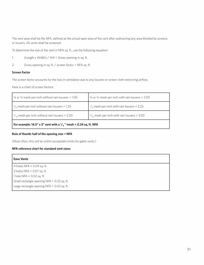
91
The vent area shall be the NFA, defined as the actual open area of the vent after subtracting any area blocked by screens or louvers. All vents shall be screened.
To determine the size of the vent in NFA sq. ft., use the following equation:
1. (Length x Width) / 144 = Gross opening in sq. ft.
2. Gross opening in sq. ft. / screen factor = NFA sq. ft.
Screen Factor
The screen factor accounts for the loss in ventilation due to any louvers or screen cloth restricting airflow.
Here is a chart of screen factors:
¼ or ½ mesh per inch without rain louvers = 1.00 ¼ or ½ mesh per inch with rain louvers = 2.00
1/8 mesh per inch without rain louvers = 1.25 1/8 mesh per inch with rain louvers = 2.25
1/16 mesh per inch without rain louvers = 2.00 1/16 mesh per inch with rain louvers = 3.00
For example: 14.5” x 3” vent with a 1/8 ” mesh = 0.24 sq. ft. NFA
Rule of thumb: half of the opening size = NFA
(Most often, this will be within acceptable limits for gable vents.)
NFA reference chart for standard vent sizes:
Eave Vents
4 holes NFA = 0.09 sq. ft. 3 holes NFA = 0.07 sq. ft. 1 hole NFA = 0.02 sq. ft. Small rectangle opening NFA = 0.25 sq. ft. Large rectangle opening NFA = 0.42 sq. ft.

92
Attic Ventilation
Roof jacks 7” diameter NFA = 0.21 sq. ft. Roof jacks 8” diameter NFA = 0.28 sq. ft. Roof jacks 9” diameter NFA = 0.35 sq. ft. Roof jacks 12” diameter NFA = 0.38 sq. ft. Gable vent 12” x 18” NFA = 0.75 sq. ft. Gable vent 12” x 24” NFA = 1.50 sq. ft. Gable vent 12” x 12” NFA = 0.5 sq. ft.
BEST PRACTICE: WALL INSULATION
Home Retrofit strongly recommends that weather-resistant barriers (WRB) are repaired/replaced when affected by the installation of wall insulation. Plugs that are located at the sub-sheathing should be covered with a properly installed WRB after the plugs are sealed.
BEST PRACTICE: CARBON MONOXIDE
Home Retrofit strongly recommends that a carbon monoxide alarm be installed whenever a weatherization measure is performed.
Carbon monoxide alarms should be installed in each bedroom of a house or at minimum within 15 feet of each sleeping area. Contractors should educate their customers on the use of carbon monoxide alarms and precautions that should be taken if the alarm activates. The intention of the alarm is to warn occupants before they experience the symptoms of carbon monoxide poisoning.
BEST PRACTICE: HEATING SYSTEMS
Home Retrofit recommends that heating equipment be sized in accordance with Manual S, Manual D, Manual J, Spec Pro or another industry-accepted HVAC calculation methodology based on building heating loads. The equipment manufacturer’s selection procedures and sizing guidelines should be referenced as part of the HVAC planning and sizing process.
BEST PRACTICE: DUCTLESS HEAT PUMPS
Size the unit appropriately to the space to be conditioned; oversized systems negatively impact unit performance.
For optimal performance of the unit, the program recommends using risers between the unit and the permanent pad. Adjustable risers will help prevent debris and snow buildup and allow for better drainage. Riser blocks specifically manufactured/intended for this purpose should be used. The riser blocks should be mechanically or chemically secured to the pad. A pan heater can prevent defrost discharge from freezing inside the compressor and is recommended in extreme climates.
Educate homeowner on filter cleaning and other manufacturer recommended maintenance.
For more information on installation best practices for DHPs, see NW Ductless Heat Pump project’s Best Practice Guide: https://goingductless.com/assets/documents/uploads/DHP_BP-Guide_FNL.pdf
For additional information on supplementing electric forced air furnaces with ductless heat pumps, see https://www.bpa.gov/ee/technology/ee-emerging-technologies/projects-reports-archives/documents/dhp_faf_dec_12.pdf.

93
BEST PRACTICE: GAS FURNACES
For gas furnaces, Home Retrofit recommends installing programmable thermostats that can be programmed with a setback. Condensate lines should be installed within the conditioned space of the house to prevent condensate from freezing and obstructing the line.
BEST PRACTICE: HEAT PUMPS
Home Retrofit recommends that the maximum line set length be less than or equal to the manufacturer’s specifications, and the line set diameter shall match the manufacturer’s recommendations. Line sets should be insulated over their entire length.
Home Retrofit recommends the air handler be checked for adequate airflow using a TrueFlow Air Handler Flow MeterTM split method.
Refrigerant charge should be installed in accordance with the manufacturer’s specifications. Airflow should be a minimum of 325 CFM per ton.
The balance point should be within 5° (plus or minus) of 30°F.
Home Retrofit recommends heat pump installations use control strategies that minimize unnecessary use of auxiliary heat. In all systems, auxiliary heat should be set up to not operate during a first stage heating call (unless system is switched to emergency heat.) Controls should be in place so that auxiliary heat will not be engaged if the outdoor temperature is above 35°F, unless supplemental heating is required for defrost cycle or for emergency heating.
BEST PRACTICE: MANUFACTURED HOMES
Appliances with a properly installed combustion chamber sealed to the exterior of the structure are not considered combustion appliances for the purposes of the CAZ test. Forced-air system operation should not depressurize a CAZ by more than minus 3 pascals with reference to outside.
Home Retrofit recommends sealing ducts before installing underfloor insulation.
BEST PRACTICE: SPRAY-FOAM INSULATION
Customers should be notified if spray-foam insulation will limit access to electrical services, natural gas lines, HVAC system components or plumbing.
BEST PRACTICE: WATER HEATERS
If ducting is installed, apply duct insulation and a vapor barrier, or use suitable plastic ducting, to prevent condensation formation on ductwork.
Installed ducting should be done to manufacturer’s specifications, with manufacturer-approved parts.
Avoid installations near bedrooms or living rooms; if unavoidable, consider using noise dampening features in the space or isolate vibration if noise is a concern. Also consider homeowner comfort impacts of cold air exhaust.
Refer to manufacturer’s specifications for efficient mode operation.
Demonstrate filter access and maintenance to homeowner.
Any plumbing lines in unconditioned space should be insulated to prevent energy loss and frozen pipes.
Home Retrofit suggests Tier 1 heat pump water heaters not be installed in conditioned space.

94
BEST PRACTICE: WINDOWS
To improve durability and limit pathways for moisture intrusion, Home Retrofit strongly recommends the installation of flanged windows when replacing existing flanged windows.