specifications & tube boom capacities hc 238h ii · link‐belt cranes hc-238h ii technical...
TRANSCRIPT

15637 (supersedes 5503)-0613-H9
HC-238H IILink‐Belt Cranes
Technical DataSpecifications & Tube Boom Capacities
HC−238H IITruck Crane
150 Ton (136.08 metric ton)
CAUTION: This material is supplied for reference useonly. Operator must refer to in-cab Crane RatingManual and Operator's Manual to determineallowable crane lifting capacities and assembly andoperating procedures.

5637 (supersedes 5503)-0613-H9
HC-238H II Link‐Belt Cranes

15637 (supersedes 5503)-0613-H9
HC-238H IILink‐Belt Cranes
Table Of Contents
Pages
Specifications 1-12
Tube Boom Capacities 1-16
Tube Boom + Jib Capacities 1-20

5637 (supersedes 5503)-0613-H9
HC-238H II Link‐Belt Cranes
This page intentionally left blank

Litho in U.S.A. 6/13 #5637 (Supercedes #5503)
SpecificationsLattice Boom Truck Crane
HC−238H II 150−ton (136.08 metric ton)
HYLAB Series
of Rotation
General Dimensions feet meters
Minimum ground clearance 11” .28(at bottom of front bogie beam)
Ground clearance under counter−weigh with machine on tires 5’ 9” 1.75
Vehicle turning diameter − Centerlineoutside front tire 106’ 0” 32.30
Vehicle turning diameter − Outside ofouter front tire (curb clearance) 107’ 3” 32.69
Vehicle clearance over front bumper 111’ 8” 34.03
Vehicle clearance over “A” frontbumper counterweight 112’ 9” 34.36
Tailswing of “AB” counterweight 15’ 11” 4.85
Tailswing of “A” counterweight 15’ 4.57
Tailswing of “0” counterweight 13’ 10” 4.22
13’ 3”(4.04 m)
8' (2.44 m)
80�
5’ 11.5”(1.82 m)
10’ 4”(3.15 m)
11’ 11”(3.63 m)
9’ 6”(2.90 m)
15’ 11”(4.85 m)
26’ (7.92 m)
28’ 1” (8.56 m)
11’ (3.35 m)
25’ 6” (7.77 m)
22’ 8” (6.91 m)
34” (0.86 m)
50’(15.24 m)
HC−238H II
of Rotation
12’ 8”(3.86 m)
33’ 8” (10.26 m)Maximum Height
Above Ground
10’ 11” (3.33 m)Maximum RadiusFrom Centerline
of Rotation
3’ 3”(0.99 m)
CL
CL

HC−238H II − 2 −
HC−238H II Machine Transport Weights and Dimensions − approximate
54.5”(1.38 m)
54.5”(1.38 m)
20’ 7” (6.27 m) 34’ 7.25” (10.55 m)
23’ 6” (7.16 m)
13’ 3”(4.04 m)
83’ 3” (25.37 m)
23’ 6” (7.16 m)18’ 2” (5.54 m)
12’ 9.5”(3.90 m)
Axle weights with basic boom, with/without pusher axle, front O/R box and with/without rear O/R box. (Includes ropes and standard backstops)
GVW Front Rear Pusher Dolly
With rear O/R box and pusher axle 120,388 (54 607) 33,134 (15 029) 48,623 (22 055) 20,000 (9 072) 18,630 (8 450)Without rear O/R box and with pusher axle 110,434 (50 092) 35,845 (16 259) 35,959 (16 311) 20,000 (9 072) 18,630 (8 450)Without rear O/R box and without pusher axle 108,184 (49 071) 41,244 (18 708) 48,310 (21 913) not applicable 18,630 (8 450)
A − 8’ 4.25” (2.55 m) Track (rear)B − 8’ 9” (2.67 m) Track (front)
Link−Belt
Link−Bel
Axle weights with boom base, with/without front outrigger box and with/without pusher axle. (Includes ropes and standard backstops)
GVW Front Rear Pusher
With front O/R box and with pusher axle 99,789 (45 264) 31,699 (14 378) 48,090 (21 813) 20,000 (9 072)With front O/R box and without pusher axle 97,539 (44 243) 37,098 (16 827) 60,441 (27 416) not applicableWithout front O/R box and with pusher axle 90,741 (41 159) 26,504 (12 022) 44,237 (20 066) 20,000 (9 072)Without front O/R box and without pusher axle 88,491 (40 139) 31,902 (14 471) 56,589 (25 668) not applicable
* − see below for dolly weight
* − Dolly weight = 5,000 lbs. (2 268 kg) −− Dolly weights vary. Refer to manufacturers weight when determining axle loads.
60’ 7” (15.39 m)
23’ 6” (7.16 m)18’ 2” (5.54 m)
Axle weights with boom base, 10 ft. section, front outrigger box, and with/without pusher axle. (Includes ropes and standard backstops)
GVW Front Rear Pusher Dolly
With pusher axle 108,044 (49 008) 35,923 (16 294) 40,644 (18 436) 20,000 (9 072) 11,476 (5 205)Without pusher axle 105,794 (47 987) 41,322 (18 743) 52,996 (24 039) not applicable 11,476 (5 205)
A
BLive Mast Over Rear
20’ 7” (6.27 m)Live Mast over front
37’ 11” (10.34 m)
23’ 6” (7.16 m)
13’ 3”(4.04 m) 12’ 10”
(3.91 m)
Axle weights Live Mast, without pusher axle and without front or rear O/R box. (Includes ropes and standard backstops)
GVW Front Rear
Live mast over front 85,334 (38 707) 38,520 (17 472) 46,814 (21 234)Live mast over rear 85,334 (38 707) 33,054 (14 993) 52,280 (23 714)
* − see below for dolly weight
12’ 9.5”(3.90 m)

HC−238H II− 3 −
“B” Counterweight 19,330 lbs. (8 768 kg)
“C” Counterweight 21,110 lbs. (9 575 kg)
“A” Counterweight 23,000 lbs. (10 432 kg)Rear Outrigger Box Assembly
9,954 lbs. (4 515 kg)
Front Outrigger Box Assembly9,048 lbs. (4 104 kg)
Link-Belt
1’ 9.75” (0.55 m)
4’ 1.5” (1.26 m)
3’ 9” (1.14 m)
4’ 4”(1.33 m)
4’ 4”(1.33 m)
2’ 4.75” (0.73 m)
10’ 11.5”(3.34 m)
10’ 11.5”(3.34 m)
10’ 11.5”(3.34 m)
3’ 9” (1.14 m)
4’ 1.25”(1.25 m)
3’ 10.5” (1.18 m)
3’ 3”(0.99 m)
Front Bumper Counterweight 13,500 lbs. (6 123 kg)2’ 6” (0.76 m)
11’ (3.35 m)1’ 5.75” (0.45 m)
HC−238H II Machine Transport Weights and Dimensions −approximate
30’ (9.14 m) Basic Jib AssemblyTube: 1,965 lbs. (891 kg)
31’ 1” (9.5m)
2’ 6”(0.8 m)
4’ 4”(1.32 m)
20’ (6.1 m) Base SectionTube: 3,350 lbs. (1 520 kg)
30’ (9.14 m) Top SectionTube: 4,890 lbs. (2 218 kg)
62” (1.57 m)
32’ 10”(10.01 m)
20’ 6”(6.25 m)
HC−238H II Transportation Weights − approximate
Base Machine: 85 gallons (321 L) of carrier fuel, 12−part boom hoist reeving, rigid boom backstops, auxiliary lifting bail, 950’ (290 m) front hoist rope, 600’ (182.88 m)rear hoist rope and 77 gallons (291 L) of upper fuel
Item DescriptionGross Weight Transport Loads Notes and Load Summary
Numbers in the load columns to theleft represent quantities.
Estimated transport assumes theload out consist of 260’ (79.25 m) oftube boom + 75’ (22.86m) of jib withfull counterweight.
Support loads were targeted at45,000 lb (20 412 kg), 8’ 6” (2.6 m)wide, 48’ (14.6 m) long, and 13’ 6”(4.1 m) high using a drop deck trail-er. This may vary depending on statelaws, empty truck/trailer weights, andstyle of trailer.
Estimated weights vary by +/− 2%.
Estimated Total Load of #185,080 lbs. (38 592 kg).
Estimated Total Load of #2 42,656 lbs. (19 348 kg).
Estimated Total Load of #344,964 lbs. (20 395 kg).
Estimated Total Load of #424,351 lbs. (11 045 kg)
Estimated Total Load of #53,241 lbs. (1 470 kg)
Estimated Total Load of #63,241 lbs. (1 470 kg).
Estimated Total Load of #73,241 lbs. (1 470 kg)
Estimated Total Load of #88,049 lbs. (3 651 kg)
lbs. kg. #1 #2 #3 #4 #5 #6 #7 #8
Base Machine 85,080 38 592 1
Add Front outrigger box with manual pins 9,048 4 101 1
Add Hydraulic pins to front outrigger box 647 293
Add Rear outrigger box with hydraulic pins 9,954 4 515 1
Add “A” bumper counterweight 13,500 6 123 1
Add Main outrigger floats 660 299 1
Add Front outrigger float 80 36 1
Add “A” counterweight 23,000 10 433 1
Add “B” counterweight 19,330 8 768 1
Add “C” counterweight 21,110 9 575 1
Add Upper Catwalk − Left Side 154 70
Add 20’ (6.10 m) Boom base section 3,350 1 520 1
Add 30’ (9.14 m) Boom top section 4,890 2 218 1
Add 10’ (3.05 m) Boom extension 973 441
Add 10’ (3.05 m) Boom extension with lifting sheaves 2,607 1 183
Add 10’ (3.05 m) Boom extension − luffer ready 3,162 1 434 1
Add 20’ (6.10 m) Boom extension 1,537 697 1
Add 30’ (9.14 m) Boom extension 2,115 959
Add 40’ (12.19 m) Boom extension 2,678 1 215
Add 50’ (15.24 m) Boom extension 3,241 1 470 1 1 1 1
Add Auxiliary tip extension 640 290
Add Hydraulic third drum to boom base section 0 0
Add Third drum fleeting sheave for luffer to boom base section 176 80
Add Third drum 3−sheave assembly to boom top section 381 173
Add Third drum controls for free spooling 100 45
Add 30’ (9.14 m) Tubular Jib 1,683 763 1
Add 15’ (4.57 m) Tubular Jib Extension 317 144 3
Add Basic luffing attachment 10,567 4 793
Add Luffing jib top with nose wheel 2,851 1 293
Add 10’ (3.05 m) luffing jib extension 688 312
HC−238H II − 4 −
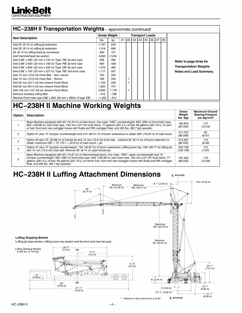
HC−238H II Transportation Weights − approximate (continued)
Item DescriptionGross Weight Transport Loads
Refer to page three for
Transportation Weights
Notes and Load Summary.
lbs. kg. #1 #2 #3 #4 #5 #6 #7 #8
Add 20’ (6.10 m) luffing jib extension 1,197 543Add 30’ (9.14 m) luffing jib extension 1,518 68930’ (9.14 m) luffing fixed jib conversion 280 127Add Hammerhead top section 4,950 2 245Add 0.88” x 465’ (22 mm x 142 m) Type ‘DB’ jib wire rope 628 285Add 0.88” x 600’ (22 mm x 183 m) Type ‘RB’ jib wire rope 900 408Add 0.88” x 805’ (22 mm x 245 m) Type ‘DB’ jib wire rope 1,070 485Add 0.88” x 745’ (22 mm x 227 m) Type ‘RB’ 3rd drum rope 1,117 507Add 15−ton (13.6 mt) Hook Ball − Non−swivel 750 340Add 15−ton (13.6 mt) Hook Ball − Swivel 760 345 1Add 25−ton (22.7 mt) two sheave Hook Block 1,164 528 1Add 60−ton (54.4 mt) two sheave Hook Block 1,650 747Add 140−ton (127 mt) six sheave Hook Block 2,600 1 179 1Remove Auxiliary Lifting Bail −410 −186Remove Front hoist rope 0.88” x 950’ (22 mm x 290m) of type ‘DB’ −1,350 −612
HC−238H II Machine Working WeightsOption Description
GrossWeightlbs. (kg)
Maximum GroundBearing Pressure
psi (kg/cm2)
1Base Machine equipped with 50’ (15.24 m) of tube boom, live mast, “ABC” counterweight, 950’ (290 m) front hoist rope,600’ (182.88 m) rear hoist rope, 140−ton (127 mt) hook block, 77 gallons (291.4 L) of fuel, 85 gallons (321.76 L) of carri-er fuel, front and rear outrigger boxes with floats and fifth outrigger float, and 200 lbs. (90.7 kg) operator.
183,875(83 404)
177(12.44)
2 Option #1 plus “A” bumper counterweight and 210’ (64.01 m) of boom extensions to obtain 260’ (79.25 m) of main boom. 211,723(96 306)
92(6.47)
3 Option #2 plus 75’ (22.86 m) of tubular jib and 15−ton (13.6 mt) hook ball − subtract 30’ (9.14 m) of boom extension toobtain maximum 230’ + 75’ (70.1 + 22.9 m) of main boom + jib.
212,597(96 432)
115(8.09)
4 Option #1 plus “A” bumper counterweight, 140’ (42.67 m) of boom extensions, luffing boom top, 160’ (48.77 m) luffing jib,and 15−ton (13.6 mt) hook ball. Remove 30’ (9.14 m) open throat top.
222,126(100 756)
112(7.87)
5
Base Machine equipped with 35’ (10.67 m) of Hammerhead boom, live mast, “ABC” upper counterweight and “A”bumper counterweight, 950’ (290 m) front hoist rope, 600’ (182.88 m) rear hoist rope, 140−ton (127 mt) hook block, 77gallons (291.4 L) of fuel, 85 gallons (321.76 L) of carrier fuel, front and rear outrigger boxes with floats and fifth outriggerfloat, and 200 lbs. (90.7 kg) operator.
197,435(89 555)
172(12.09)
Minimum85’ (25.91 m)
Maximum165’ (50.29 m)
30’(9.14 m)
Minimum80’ (24.38 m)
Maximum160’ (48.77 m)
8’ 1“ (2.48 m)16.5’ (5.04 m)
3’ (0.9 m)
15’ 11” (4.85 m)* − 21’ 7”(6.59 m)
12’ 7”(3.85 m)
24’ 7”(7.51 m)
8’ (2.44 m)
* − Maximum value when boom is at 90� ROTATION C L
HC−238H II Luffing Attachment Dimensions
13”(0.33m)
25”(0.63 m)
47’ 11”(14.6 m)
11’ 8”(3.5 m)
14’ 5”(4.4 m)
26’ 0”(7.9 m) CG
Luffing Shipping ModuleLuffing jib base section, luffing boom top section and the front and rear fan post.
Luffing Shipping Module8,250 lbs. (3 742 kg)
ROTATION C L
CG

HC−238H II− 5 −
1 2
3
4
5
6
7
8
9
40
34
39
38
ROTATION C L
1. Fixed Jib Frontstay Pendant
2. Fixed Jib Mast
3. Fixed Jib Mast Deflector Sheaves
4. Luffing Jib Head Sheaves
5. Fixed Jib Backstay Pendant
6. Luffing Jib Pendants7. Backstop Deflector/Targets
8. Luffing Jib Backstops
9. Front Fan Post
10. Upper Link
11. Top Section Idler Sheaves
12. Lower Link
13. Pendant Deflector Sheaves
14. Rear Fan Post15. Tensiometer(s)
16. Luffing Boom Pendants
17. Fan Post Pendants
18. Bridle Guide Assembly
19. Luffing Jib Hoist Bridle
20. Luffing Jib Hoist Reeving - Eight (8) Part
21. Luffing Jib Bail
22. Luffing Jib Hoist Rope23. Third Drum Fleeting Sheave
24. Luffing Boom Backstops
25. Luffing Boom Live Mast
26. Luffing Boom Hoist Bridle
27. Luffing Boom Hoist Rope
28. Luffing Boom Hoist Bail
29. “ABC” Upper CTWT
30. Bumper Counterweight31. Third Drum Winch
32. 20 ft. (6.1 m) Luffing Boom Base Section
33. 10 ft. (3.05 m) Luffing Boom Self Assembly Section
34. Latch System
35. Luffing Boom Extensions
36. 5 ft. (1.5� m) Luffing Boom Top Section
37. Top Section Auxiliary Sheaves
38. 20 ft. (6.1 m) Luffing Jib Base Section39. Luffing Jib Extensions
40. 20 ft. (6.1 m) Luffing Jib Tip Section
41. Hook Block
42. Luffing Jib Load Hoist Rope
43. Luffing Jib Nose Wheel
44. Fixed Jib Base Section
45. Fixed Jib Backstop Pendant
46. Hook Ball47. Fixed Jib Load Hoist Rope
48. Fixed Jib Tip Section
49. Fixed Jib Nose Wheel
49
48
47
46 45
44
43
42
41 40
34
10
11
12
13
14
15
16
17
18
19
20
21
22
24
25
26
27
28
29
30
23
31
32
33
34
35
36
37
HC−238H II Luffing Attachment Nomenclature

HC−238H II − 6 −
Attachment Options� 50’ − 260’ (15.24 −
79.25 m) Open Throat Boom
Basic Boom − 50’ (15.24 m) two−piecedesign that utilizes a 20’ (6.10 m) base sectionand a 30’ (9.14 m) open throat top section within−line connecting pins. Boom extensions are70” (1.78 m) wide and 62” (1.57 m) deepcenters.� 135−ton (122.47 mt) maximum capacity� Boom feet on 55” (1.40 m) centers� 4” (0.10 m) “HX” diameter chords� Top section includes mounting lugs for all
optional attachments.� Lugs on base section to attach carrying
links.� Skywalk platform� Base section has mounting lugs for optional
third hoist drum.� Permanent skid pads mounted on top
section to protect head machinery� Six, 20.5” (0.52 m) root diameter steel
sheaves mounted on sealed anti−frictionbearings
� Mechanical boom angle indicator� Deflector roller on top section� Quick reeve boom topBoom Extensions − The following table pro−vides the lengths available and the suggestedquantity to obtain maximum boom in 10’ (3.05m) increments. Midpoint pendant connectionsare required at 110’ (33.53 m) for boomlengths of 250’ (76.2 m) and 260’ (79.25 m).
Boom Extensions Suggested Quantityfor Max. Boom
10’ (3.05 m) With orwithout lifting sheaves 1
20’ (6.10 m) 1
30’ (9.14 m) 0
40’ (12.19 m) 2
50’ (15.24 m) 2
� Deflector roller on top of each section� Appropriate length pendants� Maximum boom tip height of 264’ (80.47 m)� 10’ (3.05 m) extensions with lifting sheaves
is available for self assembly/disassembly.
� 35’ (10.67 m) Hammer Head Boom
Three−piece design that utilizes a 20’ (6.10 m)base section, a 10’ (3.05 m) transitionextension and a 5’ (1.5 m) head top sectionwith in−line connection pins.� 150−ton (136 mt) maximum capacity� Maximum boom tip height of 42’ (12.80 m)� Boom feet on 55” (1.40 m) centers� 4” (0.10 m) “HX” diameter chords� Lugs on base section to attach carrying links� Skywalk platform� Deflector roller on top section� Rigid sheave guards� Seven, 20.62” (0.52 m) root diameter steel
sheaves mounted on sealed anti−frictionbearings
� Mechanical boom angle indicator
� 30’ − 75’ (9.14 − 22.86 m) Fixed Jib
Basic Fixed Jib − 30’ (9.14 m) two−piecedesign that utilizes a 15’ (4.57 m) base sectionand a 15’ (4.57 m) top section with in−lineconnecting pins on 32” (0.81 m) wide and 24”(0.61m) deep centers.� 2” (38.1 mm) “BK” diameter chords� One 18.5” (0.47 m) root diameter steel
sheave mounted on sealed anti−frictionbearings.
� 15’ (4.57 m) jib extensions provide jiblengths at 45’ (13.72 m), 60’ (18.29 m) and75’ (22.86 m).
� Jib offset angles at 5, 15 and 25 degrees� Maximum tip height of open throat boom +
fixed jib is 308’ (93.87 m).
� 80’ − 160’ (24.38 − 48.77 m) Luffing Jib
Basic Luffing Jib − 80’ (24.38 m) five−piecedesign utilizes a 5’ (1.52 m) luffing boom topsection, 20’ (6.10 m) base section, 10’ (3.05m) extension, 30’ (9.14 m) extension, and 20’(6.10 m) top section with in−line connectingpins. Boom extensions are 44” (1.12 m) wideand 54” (1.37 m) deep at the centers.� 27−ton (24.5 mt) maximum capacity� Working lengths of 80’ (24.38 m) to 160’
(48.77 m).� Top section includes mounting lugs for all
attachment options� Lugs on base section to attach fan−post
transport links� Two steel 18” (0.46 m) diameter luffing jib
head sheaves� Two polyamide 21.25” (0.54 m) diameter
luffing boom auxiliary head sheaves� Pin−on nose wheel� Eight−part luffing jib hoist.� 1.25” (31.75 mm) diameter type “N”
pendantsLuffing Jib Extensions − The following tableprovides the lengths available and thesuggested quantity to obtain the maximumluffing jib in 10’ (3.05 m) increments. Midpointpendants are not required.
Luffing JibExtensions
Suggested Quantityfor Max. Boom
10’ (3.05 m) 0
20’ (6.10 m) 1
30’ (9.14 m) 2
Note: Extensions and pendants are commonwith the LS−138H, LS−138H II, LS−208H andLS−208H II.� Deflector roller on top of each extension� Appropriate length pendants� Max. luffing jib tip height of 326’ (99.36 m)
� 30’ (9.14 m) Fixed Jib� Common fixed jib used on open throat boom.� Maximum luffing jib plus fixed jib tip height
of 347’ (105.77 m)
� 85’ − 165’ (25.91 − 50.29 m) Luffing Boom
� Common base and extensions as openthroat boom
� 10’ (3.05 m) luffing extension required forbail anchor
� Working angles of 90, 85, 80, 75, 70, and 65degrees.
� Working lengths of 85’ (25.91 m) to 165’(50.29 m)
� 1.38” (34.92 mm) diameter type “N”pendants; same as open throat boom.
Luffing Boom Extensions − The followingtable provides the lengths available and thesuggested quantity to obtain the maximumluffing boom in 10’ (3.05 m) increments.Midpoint pendants are not required.
Luffing BoomExtensions
Suggested Quantityfor Max. Boom
10’ (3.05 m) Luffer Ready 1
20’ (6.10 m) 1
30’ (9.14 m) 0
40’ (12.19 m) 2
50’ (15.24 m) 2
� Rear hoist drum becomes luffing jib hoist� Optional third drum provides second
working hoist line, if required.� Designed for self−assembly� Luffing jib hoist bridle and bail can remain
reeved for machine transport� Job site mobility with attachment� Rolled out or rolled under erection methods� Compact transport module.
� Auxiliary 5’ (1.5 m)Tip Extension
Designed to use instead of a jib to provideclearance between working hoist lines. Theextension is equipped with two 18” (0.46 m)root diameter nylon sheaves mounted onsealed anti−friction bearings. Maximumcapacity is 9−ton (8.16 mt).
� Boom Hoist SystemDesigned to lift off maximum boom ormaximum boom plus jib unassisted. Operatesup to a maximum boom angle of 80 degrees.Automatically limits maximum boom angleoperation.� Pin−on bail frame� 12−part reeving with 7/8” (22.23 mm) type
‘LB’ wire rope� Bridle assembly� Two 1.38” (35.05 mm) pendants� Tubular spring buffered boom backstops
(rigid type) − standard� Tubular spring buffered hydraulic boom
backstops are optional to flip mast to rear ofupper.
� Steel sheaves contain sealed anti−frictionbearings.
� Boom speed from 0 to 82 degrees is 96seconds with no load. Speed determinedusing 200’ (60.96 m) of boom.
HC−238H II− 7 −
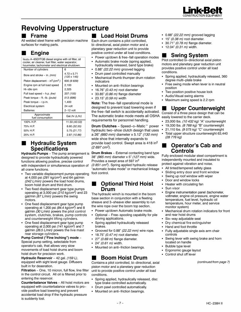
Revolving Upperstructure� FrameAll welded steel frame with precision machinesurfaces for mating parts.
� EngineIsuzu A−6SDITQB diesel engine with oil filter, oilcooler, air cleaner, fuel filter, water separator,hourmeter, tachometer and electrical shutdown.
Number of cylinders 6
Bore and stroke − in. (mm) 4.72 x 5.71(120 x 145)
Piston displacement − in3.(cm3 ) 600 (9 839)
Engine rpm at full load speed 2,100
Hi−idle rpm 2,325
Full load speed − h.p. (kw) 207 (155)
Peak torque − ft.−lb. (joule) 513 (696)
Peak torque − r.p.m. 1,400
Electrical system 24 volt
Batteries 2−12 volt
Approximatefuel consumption Gal./hr (L/hr)
100% H.P. 11.50 (43.53)
75% H.P. 8.60 (32.55)
50% H.P. 5.75 (21.77)
25% H.P. 2.87 (10.86)
� Hydraulic SystemSpecifications
Hydraulic Pumps − The pump arrangement isdesigned to provide hydraulically poweredfunctions allowing positive, precise controlwith independent or simultaneous operation ofall crane functions.� Two variable displacement pumps operating
at 4,000 psi (281 kg/cm2) and 64 gal/min(242 L/min) powers the load hoist drums,boom hoist drum and third drum.
� Two fixed displacement gear type pumpsoperating at 3,000 psi (210 kg/cm2) and 23gal/min (87 L/min) powers the swingmotors.
� One fixed displacement gear type pumpoperating at 1,200 psi (84.4 kg/cm2) and 8gal/min (30 L/min) powers the pilot controlsystem, clutches, brakes, pump controlsand counterweight lifting cylinders.
� One fixed displacement gear type pumpoperating at 2,000 psi (141 kg/cm2) and 7gal/min (26.5 L/min) powers the live mastrear storage cylinders.
Pump Control (“Fine Inching”) mode −Special pump setting, selectable fromoperator’s cab, that allows very slowmovements of load hoist drums and boomhoist drum for precision work.Hydraulic Reservoir − 42 gal. (159 L),equipped with sight level gauge. Diffusers built in for deaeration.Filtration − One, 10 micron, full flow, line filterin the control circuit. All oil is filtered prior toentering the reservoir.Counterbalance Valves − All hoist motors areequipped with counterbalance valves to pro−vide positive load lowering and preventaccidental load drop if the hydraulic pressureis suddenly lost.
� Load Hoist DrumsEach drum contains a pilot controlled,bi−directional, axial piston motor and aplanetary gear reduction unit to providepositive control under all load conditions.� Power up/down & free−fall operation modes� Automatic brake mode (spring applied,
hydraulically released, band type brake)� 0.88” (22.22 mm) grooved lagging� Drum pawl controlled manually� Mechanical thumb thumper drum rotation
indicators� Mounted on anti−friction bearings� 16.76” (0.43 m) root diameter� 33.85” (0.86 m) flange diameter� 23.15” (0.59 m) width
Note: The free−fall operational mode isdesigned to prevent load lowering even ifthe free−fall switch is accidentally activated.The automatic brake mode meets all OSHArequirements for personnel handling.
Drum Clutches − Speed−o−Matic� powerhydraulic two−shoe clutch design that usesa 26” (660 mm) diameter x 5.12” (130 mm)wide shoe that internally expands toprovide load control. Swept area is 418 in2
(2 697 cm2).
Drum Brakes − External contacting band type38” (965 mm) diameter x 5” (127 mm) wide.Provides a swept area of 597 in2 (3 851 cm2). Spring applied hydraulic release“automatic brake mode” or mechanical linkagefoot control.
� Optional Third Hoist Drum
The hydraulic winch is mounted in the boombase section in conjunction with a fleetingsheave and 3−sheave idler assembly to runthe wire rope over the boom top section.� Power up/down Automatic brake mode.� Optional − Free−spooling capability for pile
driving applications.� Spring applied hydraulically released
brakes.� Grooved for 0.88” (22.22 mm) wire rope.� 18.75” (0.47 m) root diameter.� 27” (0.69 m) flange diameter.� 24” (0.61 m) width.� Mounted on anti−friction bearings.
� Boom Hoist DrumContains a pilot controlled, bi−directional, axialpiston motor and a planetary gear reductionunit to provide positive control under all loadconditions.� Spring applied, hydraulically released, disc
type brake controlled automatically.� Drum pawl controlled automatically.� Mounted on anti−friction bearings.
� 0.88” (22.22 mm) grooved lagging� 15” (0.38 m) root diameter.� 30.71” (0.78 m) flange diameter.� 12.04” (0.31 m) width.
� Swing SystemPilot controlled bi−directional axial pistonmotors and planetary gear reduction unitprovides positive control under all loadconditions.� Spring applied, hydraulically released, 360
degree multi−plate brake� Free swing mode when lever is in neutral
position� Two position positive house lock� Audio/Visual swing alarms� Maximum swing speed is 2.2 rpm
� Upper CounterweightConsist of a three piece design that can beeasily lowered to the carrier deck.� 23,000 lbs. (10 432 kg) “A” counterweight� 19,330 lbs. (8 768 kg) “B” counterweight� 21,110 lbs. (9 575 kg) “C” counterweight� Total upper structure counterweight 63,440
(28 776 kg)
� Operator’s Cab andControls
Fully enclosed modular steel compartment isindependently mounted and insulated toprotect against vibration and noise.� All tinted/tempered safety glass� Sliding entry door and front window� Swing up roof window with wiper� Door and window locks� Heater with circulating fan� Sun visor� Engine instrumentation panel (tachometer,
voltmeter, engine oil pressure, engine watertemperature, fuel level, hydraulic oiltemperature, hour meter, and servicemonitor system)
� Mechanical drum rotation indicators for frontand rear hoist drums
� Six−way adjustable seat� Dry chemical fire extinguisher� Hand and foot throttle� Fully adjustable single axis arm chair
controls� Swing lever with swing brake and horn
located on handle� Bubble type level� Ergonomic gauge layout� Control shut off lever
(continued from page 7)
HC−238H II − 8 −
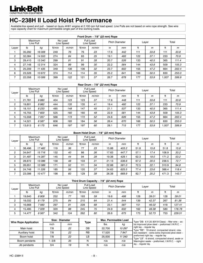
HC−238H II Load Hoist PerformanceAvailable line speed and pull − based on Isuzu 4HK1 engine at 2,100 rpm full load speed. Line Pulls are not based on wire rope strength. See wirerope capacity chart for maximum permissible single part of line working loads.
Front Drum − 7/8” (22 mm) Rope
MaximumLine Pull
No LoadLine Speed
Full LoadLine Speed Pitch Diameter Layer Total
Layer lb kg ft/min m/min ft/min m/min in mm ft m ft m
1 35,292 16 008 249 76 76 23 17.6 442 111 33.8 111 33.8
2 32,084 14 553 274 84 83 25 19.1 493 122 37.1 233 70.9
3 29,410 13 340 299 91 91 28 20.7 526 133 40.5 365 111.4
4 27,148 12 314 324 99 99 30 22.2 564 144 43.8 509 155.3
5 25,209 11 435 349 106 106 32 23.7 602 155 47.2 664 202.4
6 23,528 10 672 374 114 114 35 25.2 641 166 50.5 830 253.0
7 22,058 10 006 399 122 121 37 26.7 678 177 53.9 1,007 306.9
Rear Drum − 7/8” (22 mm) Rope
LayerMaximumLine Pull
No LoadLine Speed
Full LoadLine Speed Pitch Diameter Layer Total
lb kg ft/min m/min ft/min m/min in mm ft m ft m
1 21,781 9 880 404 123 123 37 17.6 448 111 33.8 111 33.8
2 19,801 8 982 444 135 135 41 19.4 492 122 37.1 233 70.9
3 18,151 8 233 485 148 147 45 21.1 537 133 40.5 365 111.4
4 16,755 7 600 525 160 160 49 22.9 581 144 43.8 509 155.3
5 15,558 7 057 566 173 172 52 24.6 626 155 47.2 664 202.4
6 14,521 6 587 606 185 184 56 26.4 670 166 50.5 830 253.0
7 13,613 6 175 646 197 197 60 28.1 715 177 53.9 1,007 306.9
Boom Hoist Drum − 7/8” (22 mm) Rope
LayerMaximumLine Pull
No LoadLine Speed
Full LoadLine Speed Pitch Diameter Layer Total
lb kg ft/min m/min ft/min m/min in mm ft m ft m
1 38,496 17 462 119 36 77 23 15.88 403.2 51.8 15.8 51.8 15.8
2 34,647 15 716 132 40 86 26 17.63 447.7 57.1 17.4 108.9 33.2
3 31,497 14 287 145 44 94 29 19.38 429.1 62.3 19.0 171.2 53.2
4 28,872 13 096 158 48 103 31 21.13 536.6 67.2 20.5 238.5 72.7
5 26,651 12 089 171 52 111 34 22.88 581.0 72.5 22.1 310.9 94.8
6 24,748 11 226 185 56 120 37 24.63 625.5 77.4 23.6 388.4 118.4
7 23,098 10 477 198 60 129 39 26.38 669.9 82.7 25.2 471.3 143.7
Third Drum Capacity − 7/8” (22 mm) Rope
LayerMaximumLine Pull
No LoadLine Speed
Full LoadLine Speed Pitch Diameter Layer Total
lb kg ft/min m/min ft/min m/min in mm ft m ft m
1 19,640 8 909 252 77 193 59 19.6 498 128 39.01 128 39.01
2 18,032 8 179 275 84 210 64 21.4 544 139 42.37 267 81.38
3 16,668 7 560 297 91 228 69 23.1 587 151 46.02 418 127.41
4 15,495 7 029 320 98 245 75 24.9 632 162 49.38 580 176.78
5 14,477 6 567 342 104 262 80 26.6 675 173 52.73 753 229.51
Wire Rope ApplicationSize: Diameter
TypeMax. Permissible Load
Type “DB: 6 X 25 (6X19 Class) − filler wire − ex-tra improved plow steel − preformed I.W.R.C. −right lay − regular layType “RB”: 19 strand, compacted strand, rota-tion resistant − extra extra improved plow steel −preformed right lay − regular layType “LB”: 6 strand, compacted strand, seale orWarrington seale − preformed, I.W.R.C. − rightlay − regular lay.
inch mm lbs. kg
Main hoist 7/8 22 DB 22,700 10 297
Auxiliary hoist 7/8 22 RB 17,520 7 947
Boom hoist 7/8 22 LB 25,000 11 340
Boom pendants 1−3/8 35 N n/a n/a
Jib pendants 3/4 19 N n/a n/a

HC−238H II− 9 −
Revolving Upperstructure (continued from page 7)
� Load MomentIndicator/Limiter
Standard Equipment: PAT DS−350G/1334modular system that includes two line− riders,angle sensor, computer, graphics display, andanti two block equipment to provide thefollowing information:� Graphic representation of Machine
Configuration� Graphical step−by−step machine set−up� Boom length & angle� Jib length & angle� Load on hook� Rated load
� Load radius� Tip height� Anti−two block warning & function limiters
operation mode� Provides an audio/visual warning when the
load on hook is within 90% of the cranesrated load.
� Provides an audio/visual warning and limitsfunctions when the load on hook is at 100%of the cranes rated load.
� Operator settable alarms include maximumand minimum boom angle, maximum tipheight, left and right swing, and rangecontrol (obstacle avoidance). These alarmsprovide an audio/visual warning only.
Note: Function limiters are activated forAnti−two block and overload conditions.These limiters are designed to prevent hoistup on front, rear and third hoist drums, andboom hoist down.
� Additional Equipment− Standard
� 93” (2.36 m) outside diameter turn tablebearing
� Front, and removable right catwalks.� Left side catwalks are optional.� 77 (usable) U.S. Gallons (291.5 L) fuel tank� Upper lifting links� Two 70−watt headlights
Carrier� TypeAll welded steel frame with precisionmachined surfaces for mating parts.� 11’ 0” (3.35 m) wide� 23’ 6” (7.16 m) wheel base.� 8 x 4 drive.� 100,000 psi (689.5 mPa) alloy steel, triple
box construction.
� AxlesFront� Tubular tandem axles� 105” (2.67 m) track with single wheels.� Oil lubed wheel bearings with see through
hubcaps.� 43,660 lbs. (19 804 kg) maximum axle
loading at 56 m.p.h. (90 km/hr)Rear� Tubular tandem axles� 100.25” (2.56 m) track with dual wheels.� Oil lubed wheel bearings with see through
hubcaps.� 9.14:1 ratio with interaxle differential lockout� 85,840 lbs. (38 936 kg) maximum axle
loading at 56 m.p.h. (90 km/hr)Optional Pusher Axle� Tubular single axles� 97.75” (2.48 m) track with dual wheels.� Oil lubed wheel bearings with see through
hubcaps.� 22,000 lbs. (9 979 kg) maximum axle
loading at 56 m.p.h. (90 km/hr)� Can be air lifted to provide 4.31” (109.5
mm) clearance to ground� Air controlled
� SuspensionFront − Air−ride system, 4−bag walking beamstyle, that deflates to solid mount forincreased stability during job site travel.Rear − Solid mount, bronze bushed equalizerbeams with rubber bushed torque rods.
� WheelsFront − Hub mounted steel disc.Rear − Integral with planetary hubs.
� TiresStandard − 385/95 R25 VHS tubeless radials.� Three−star rating� Static load − 16.6 width x 24.6 radius
� BrakesService� Full air brakes on all wheel ends. Dual
circuit with modulated emergency brakes.Front� 16.5” x 6” (0.42 m x 0.15 m) S−Cam brakes.Rear� 20.25” x 7” (0.51 m x 0.18 m) S−Cam
brakes.Parking/Emergency� One spring set, air released chamber per
rear axle end. Emergency brakes applyautomatically when air pressure dropsbelow 60 psi (413.7 kPa) in both systems.
� Steering� Sheppard full integral, hydraulic power.� Steering mounted on high sides of frame to
minimize exposure to hazards.� High speed, high power system to maximize
maneuverability both on job and on theroad.
� TransmissionsMain� Eaton RTO 14908LL with 8 progressive
highway gears and 2 “super low” gears for10 forward and 3 reverse speeds.
Auxiliary� Spicer P−1241−C; used with manual
transmission; midship mounted with4−speed gearing; 2.31:1 first gear ratio.
� ElectricalFour group 31 batteries provide 12−voltoperating system and 12−volt starting with1,600 cold cranking amps available. Chargingis provided by a 130 amp alternator.
Lights� Four dual, sealed beam headlights� Front, side, and rear directional signals with
4−way hazard system� Stop and tail lights� Rear and side clearance lights� Side turn indicators� Lighted license plate bracket
� OutriggersThe outrigger system is designed with fivehydraulically controlled outriggers that providean optimal 360−degree working area andsimultaneous operation of steering andoutriggers.� The front and rear outriggers are a
double−box design that allows all fourtelescoping beams and jacks toextend/retract independently.
� Hydraulic controls are located at eachoutrigger location with the bumper outriggeroperated at the front bumper. The controlsare designed to allow both front and rearjacks to be operated from the driver’s sideof carrier if necessary.
� Vertical jack cylinders are equipped withholding valves.
� Quick−attach self−aligning rear outriggerbox with hydraulic pins.
� Quick attach self−aligning front outriggerbox with manual pins. Hydraulic pins areoptional.
� Front left outrigger jack will tilt to allow frontbox to roll under carrier frame for removal.
� 34” (0.86 m) diameter quick−release steelfloats.
� 24” (0.61 m) diameter self−storingaluminum bumper float.
Jack Reactions� Maximum 180,000 lbs. (81 648 kg) force
and 198 psi (1 365 kPa) ground bearingpressure on main outriggers
� Maximum 41,000 lbs. (18 598 kg) force and91 psi (627 kPa) ground bearing pressureon front bumper outrigger.

HC−238H II − 10 −
� Carrier EngineSpecifications
Specification Cummins ISX12
Emissions Compliance Level:
EPA 2010 (1)
Maximum AllowableSulfur Content of Fuel(PPM):
15
Numbers of Cylinders 6
Cycle 4
Bore and Stroke: inch(mm)
5.11 x 5.91 (130x150)
Piston Displacement:in3 (L)
729 (11.9)
Max. Brake Horsepower: hp (kW)
500 (373) @ 1,800rpm
460 (343) @ 2,100rpm
Peak Torque: ft lb(Nm)
1,550 (2 102) @1,200 rpm
Alternator: volts -amps
12 - 145
Crankcase Capacity:qt (L)
48 (45.4)
� Cruise control
� Three-stage engine compression brake
� Thermostatically controlled, hydraulically driven radiator fan
� 120 volt engine block heater
� Ether injection system - optional ISX(1) Complies with EPA emissions standardseffective January 2010.
� BumperCounterweight
Standard� “A” counterweight − 13,500 lbs. (6 124 kg)
� Carrier CabFully enclosed, one person. Galvaneal steelconstruction, lined with vinyl covered acous−tical insulation with sound reduction insula−tion and isolated from engine compartment.Equipped with:� Air ride seat with seat belt� 2−speed, electric windshield wiper and
washer� Tilt/telescoping steering column� Front and roof, fresh air vents� Safety plate glass on front� Sliding, tinted, rear and right side windows� Roll down door window� Door and window locks� Diagnostic connectors for engine� Fire extinguisher� 19,800 BTU heater/defroster� Rubber floor mat� Horn� Dome light� Accessory plug/lighterCab Instrumentation − Tilt−out (for serviceaccess), illuminated, instrument panelincludes:� Speedometer � Odometer� Hourmeter � Tachometer� Voltmeter
� Stop and check engine warning lights� Fuel gauge� Engine oil pressure gauge� Engine temperature gauge� Front and rear air pressure gauges
with low air pressure warning buzzer/light� Cruise controls� Engine fan override switch� Heater and defroster controls� Light controls� Park brake switch and applied light� Engine diagnostic switch
� Additional EquipmentStandard:� Towing shackles, front and rear.� Aluminum, full deck fenders and ladders� Outrigger controls located on outrigger
boxes.� Engine throttle−up control switch� West Coast−type rear view mirrors with
adjustable convex mirror� Trailer electrical and air connectors� 2−way reading bubble levels� Back−up alarm� Mud flaps� Air dryer� Lug wrench� Tire inflation system� Remote plug for block heater� 85 gal. (321.76 L) fuel tankOptional:
� Spare tires and rims
� Carrier SpeedsMain−Eaton RTO 16908LL
Auxiliary−Spicer P−1241−C
4th (0.81) 3rd (1.00) 2nd (1.24) 1st (2.37)
Gear Ratio mph km/h mph km/h mph km/h mph km/h
High
8th7th6th5th
.741.001.361.83
58.443.231.823.6
94.269.551.238.0
47.435.125.819.2
76.356.541.530.9
38.228.320.815.5
61.545.533.524.9
20.014.810.98.1
32.223.817.513.0
Low
4th3rd2nd1stL
2.533.404.636.249.42
17.112.79.36.94.6
27.520.415.011.17.4
13.910.37.65.63.7
22.416.612.29.06.0
11.28.36.14.53.0
18.013.49.87.24.8
5.94.43.22.41.6
9.57.15.13.92.6
Deep Reduction LL 14.56 3.0 4.8 2.4 3.9 1.9 3.1 1.0 1.6
Hi Rev.Lo Rev.
Rev.Rev.
2.899.85
15.04.4
24.17.1
12.13.6
19.55.8
9.82.9
15.84.7
5.11.5
8.22.4
Deep Reduction Rev. 15.22 2.8 4.5 2.3 3.7 1.9 3.1 1.0 1.6
Deep Reduction@ 600 rpm LL 14.56 0.85 1.4 0.7 1.2 .55 0.9 0.3 0.5
Deep Reduction@ 600 rpm Rev. 15.22 0.8 1.3 0.65 1.1 0.5 0.8 0.3 0.5

HC−238H II− 11 −
� Axle LoadsBase machine: Standard carrier with 85 gallons (321 L) offuel and manual front outrigger pins. Standard revolvingupperstructure with 77 gallons (291 L) of fuel, rigidbackstops, mast, bridle, bail, and 950’ (290 m) of fronthoist rope.
Gross VehicleWeight
Upper Facing Rear of Carrier Upper Facing Front of Carrier
Front Axle Rear Axle Front Axle Rear Axle
lbs. kg lbs. kg lbs. kg lbs. kg lbs. kg
85,080 38 592 32,012 14 974 52,068 23 618 25,582 11 604 59,498 26 988
Add Rear Outrigger Box w/ Hydraulic Pin Pullers 9,954 4 515 −2,711 −1 230 12,665 5 745 −2,711 −1 230 12,665 5 745
Add Front Outrigger Box w/ Manual Pins 9,049 4 104 5,195 2 357 3,853 1 748 5,195 2 357 3,853 1 748
Add Hydraulic Front Outrigger Pin Removal System 647 293 317 169 276 125 371 169 276 125
Add Main Outrigger Floats To Storage Racks 660 299 230 104 430 195 230 104 430 195
Add Bumper Outrigger Pontoon To Storage Rack 80 36 60 27 20 9 60 27 20 9
Add “A” Bumper Counterweight 13,500 6 123 16,420 7 448 −2,920 −1 325 16,420 7 448 −2,920 −1 325
Add Pusher Lift Axle (Maximum Boost) 2,250 1 021 −4,834 −2 193 −11,166 −5 065 −4,834 −2 193 −11,166 −5 065
Add Tag Axle (Customer Supplied) 7,000 3 175 7,234 3 281 −24,234 −10 993 7,234 3 281 −24,234 −10 993
Add Driver To Carrier Cab 220 100 245 111 −25 −11 245 111 −25 −11Add Hydraulic Backstops 535 243 116 52 419 190 51 23 484 219Flip Mast to rear of Upper 0 0 4,442 2 015 1,744 791 −2,505 −1 136 8,691 3 942Add 465’ (145 m) Type ‘DB’ Rear Hoist Rope 628 285 282 128 346 157 −86 −39 714 324Add 600’ (183 m) Type ‘RB’ Rear Hoist Rope 900 408 404 183 496 225 −124 −56 1,024 464Add 800’ (245 m) Type ‘DB’ Rear Hoist Rope 1,070 485 480 218 590 267 −147 −67 1217 552Add “A” Upper Counterweight 22,730 10 310 16,932 7 680 6,068 2 752 −9,755 −4 425 32,755 14 858Add “B” Upper Counterweight 19,200 8 709 12,280 5 570 7,050 3 198 −6,248 −2 834 25,578 11 602Add “C” Upper Counterweight 27,070 12 279 15,805 7 169 5,305 2 406 −9,217 −4 181 30,327 13 756Remove Wire Rope From Front Drum −1,350 −612 −378 −171 −972 −441 −43 −20 −1,307 −593Add 20’ (6.10 m) Base Section 3,350 1 520 −1,222 −554 4,572 2 074Add 10’ (3.05 m) Extension w/ Lifting Sheaves 2,607 1 183 −3,137 −1 423 5,744 2 606Add 10’ (3.05 m) Luffer Ready Extension w/o Bail 3,162 1 434 −3,361 −1 524 6,523 2 959Add Luffing Jib Bail to the 10’ Extension 1013 459 −1,248 −566 2,261 1 026Add Luffing Jib Bridle to the 10’ Extension 517 235 −668 −303 1,185 537Add Third Drum, Wire Rope and Idler to Base Section 3,515 1 594 −698 −317 4,213 1 911Add Hookblock to 10’ (3.05 m) Self−assembly Extension 2,000 907 −4,255 −1 930 6,255 2 837Add Single Axle Dolly w/ Base and Peak 15,392 6 982 1,507 684 −2,922 −1 325Add Single Axle Dolly w/ Base and 10’ (3.05 m) Self Assy. 13,002 5 898 1,588 721 1,958 888Add Tandem Axle Dolly w/ Base and Peak 17,392 7 889 1,507 684 −2,922 −1 325Add Tandem Axle Dolly w/ Base and 10’ (3.05 m) Self Assy. 15,002 6 805 1,588 721 1,958 888Add Hookblock to 10’ (3.05 m) Self−assembly (w/ Dolly) 2,000 907 −29 −13 −937 −425Add Hookblock to Boom Peak (w/ Dolly) 2,000 907 −100 −45 −3,196 −1 450
Axle Maximum Allowable Load @ 65 mph (104 km/h)
Front Tandem 43,660 lb (19 804 kg)
Rear Tandem 85,840 lb (38 937 kg)
Pusher 20,000 lb (9 072 kg)

HC−238H II − 12 −
Link−Belt Construction Equipment Company Lexington, Kentucky www.linkbelt.com�Link−Belt is a registered trademark. Copyright 2013. All rights reserved. We are constantly improving our products and therefore reserve the right to change designs and specifications.
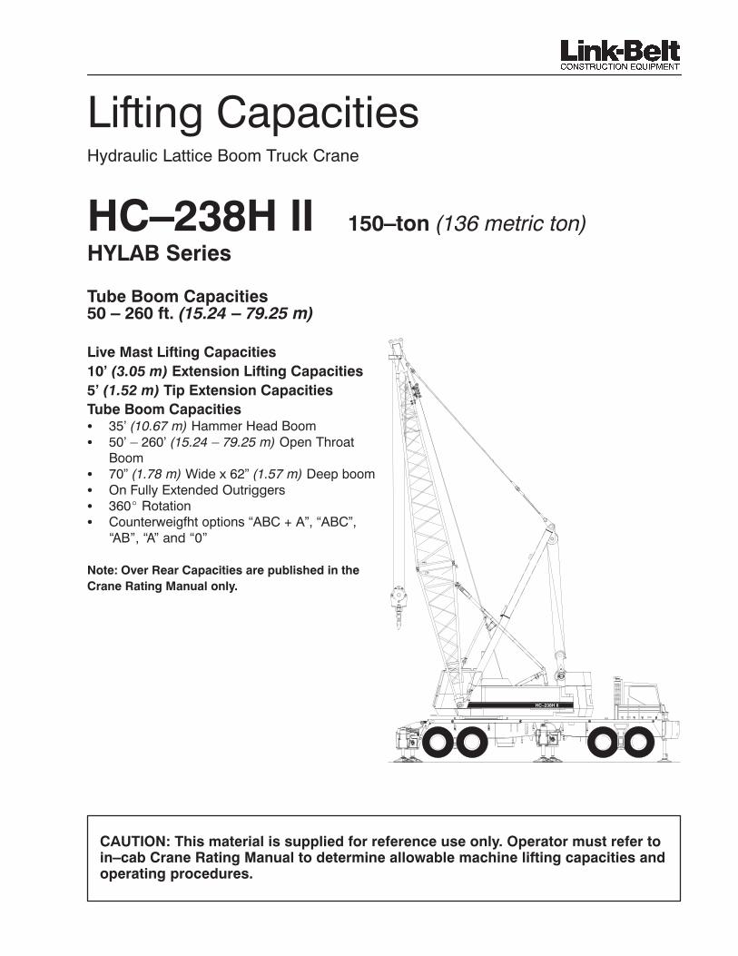
������������� �Hydraulic Lattice Boom Truck Crane
HC–238H II 150–ton (136 metric ton)���������
Tube Boom Capacities50 – 260 ft. (15.24 – 79.25 m)
�� �����������������������
��������������������������������������
��������������������������������
�� ����!����������
� 35’ (10.67 m) Hammer Head Boom� 50’ – 260’ (15.24 – 79.25 m) Open Throat
Boom� 70” (1.78 m) Wide x 62” (1.57 m) Deep boom� ������������ �� ��������� ��
� 360� Rotation� Counterweigfht options “ABC + A”, “ABC”,
����������������
"��#�$ �%���������������� &��'(�����'
����%�����������&���&)*
HC–238H II
CAUTION: This material is supplied for reference use only. Operator must refer toin–cab Crane Rating Manual to determine allowable machine lifting capacities andoperating procedures.

–2–HC–238H II
+�%","-
%��.� �".� /".�%���".� ���� $0�%��$%��� �".� ��1���� ��"/���� �".� ���
1$��$+,"-� ,"��%/��,$"�� �".� ���%�� 2��/��� ��1$%�� $0�%��,"-� ���
�%�"�*� � $0�%��,$"�+�,��� .$��� "$�� 1$��$+� ������ ,"��%/��,$"�� ���
%��/���,"��"����,.�"�*
OPERATING INSTRUCTIONS
-�"�%��#
1. Rated lifting capacities in pounds as shown on lift chartpertain to this crane as originally manufactured andnormally equipped by Link–Belt Construction EquipmentCompany (LBCE). Modifications to the crane or use ofoptional equipment other than that specified can result ina reduction of capacity.
2. Construction equipment can be dangerous if improperlyoperated or maintained. Operation and maintenance ofthis crane must be in compliance with the information inthe Operator’s, Parts and Safety manuals supplied withthis crane. If the manuals are missing, orderreplacements through the distributor.
3. The operator and other personnel associated with thiscrane shall read and fully understand the latestapplicable American National Standards Institute (ANSI)safety standards for cranes.
4. All capacities listed in this book are in compliance withASME/ANSI B30.5–1994, SAE J987–April 1994, andSAE J765–October 1990.
�,1���%�"��$0�%��,$"#
1. Capacities shown are in pounds and are not more than85% of the tipping loads on outriggers and 75% of thetipping loads on tires with crane standing level on firmsupporting surface. A deduction must be made fromthese capacities for weight of hook block, hook ball,sling, grapple, load weighing devices, etc. When usingmain hook while jib is attached, reduce capacities byvalues shown on chart “Capacity Deductions For LiftingOff Main Boom Hook With Jib Installed.” When usingmain hook while 5’ Tip Extension is attached, reducecapacities by values shown in “Capacity Deduction forLifting Off Main Hook with 5’ Tip Extension Installed”.See Operator’s Manual for all limitations when raising orlowering attachment.
2. The hammerhead boom is available only in a 35’ length.3. The crane capacities in the shaded areas are based on
structural strength or hydraulic limitations. The cranecapacities in the non– shaded areas are based onstability ratings. Some capacities are limited by amaximum obtainable 80� boom angle.
4. For recommended reeving, parts of line, wire rope typeand wire rope inspection, see Wire Rope Capacity Chartand Operators Manual.
5. For recommended reeving, parts of line, wire rope type,and wire rope inspection, see Wire Rope Capacity chart,Operator’s Manual, and Parts Manual. Rated liftingcapacities are based on correct reeving. Deductionmust be made for excessive reeving. Any reeving overminimum required is considered excessive and must beaccounted for when making lifts. Use Working RangeDiagram to estimate the extra feet of wire rope includedin reeving. Then consult Wire Rope Capacity chart todetermine the weight per foot of wire rope type. Deductthis amount for each extra foot of wire rope beforeattempting to lift a load.
6. Rated lifting capacities do not account for the effects ofwind on a suspended load or boom. Lifting capacitiesshould be considered acceptable for wind speeds lessthan 20 mph and appropriately reduced for wind speedsgreater than 20 mph. Extreme caution should be usedwhen lifting heavy loads or loads with large wind sailarea under high wind conditions (over 20 mph). SeeWind Restriction charts in this manual for appropriatecapacity reductions.
7. “On outrigger” capacities require that all four outriggerbeams are fully extended, all five jacks are extendeduntil all tires are clear of the ground and crane isproperly leveled on a firm supporting surface.
8. The least stable rated condition is over the side.9. Do not lift or suspend a load from the boom tip extension
or jib and the main boom at the same time.10. Do not swing over side until all four outrigger beams are
fully extended, all five jacks are extended until all tiresare clear of the ground and crane is properly leveled ona firm supporting surface.
11. “0+0” counterweight indicates no upper or carriercounterweight on the machine.
12. “A+0” counterweight indicates 23,000 lb. “A” uppercounterweight with no carrier counterweight.
13. “AB+0” counterweight indicates 42,330 lb. “AB” uppercounterweight with no carrier counterweight.
14. “ABC+0” counterweight indicates 63,440 lb. “ABC” uppercounterweight with no carrier counterweight.
15. “ABC+A” counterweight indicates 63,440 lb. “ABC”upper counterweight with 13,500 lb. carriercounterweight.

–3– HC–238H II
16. Midpoint pendants are required on open throat booms250 ft. and 260 ft. in length.
17. Load ratings are based on freely suspended loads andmake no allowance for such factors as the effect ofwind, ground conditions and operating speeds.Therefore the operator shall reduce load ratings in orderto take these conditions into account.
18. 45’ open throat boom consists of the 20’ boom basesection and the 25’ open throat peak section.
19. 50’–260’ boom lengths consist of the 20’ boom basesection, the appropriate length of boom extensions, andeither of the following:– 30’ open throat peak– 25’ open throat peak w/5’ open throat boom extension.
20. When using the 25’ open throat peak section with boomlengths 50’ or longer, the 5’ open throat boom extensionmust be pinned directly to the 25’ open throat peak.
PICK AND CARRY CAPACITIES:1. On tire capacities are restricted to a maximum travel
speed of 1 mph (1.6 km/h). The boom must be centeredstraight over the rear with travel swing lock engaged andthe load must be restrained from swinging.
2. Travel slowly and cautiously on a firm and levelsupporting surface.
3. Control load with taglines to prevent an increase in loadradius while traveling. Failure to control load radiuscould result in a tipping condition, or boom and jibfailure.
DEFINITIONS:1. Load Radius: Horizontal distance from a projection of
the axis of rotation to the supporting surface, beforeloading, to the center of the vertical hoist line or tacklewith load applied.
2. Boom Angle: The angle between the boom basesection and horizontal with freely suspended load at therated radius.
3. Working Area: Area measured in a circular arc aboutthe center line of rotation as shown on the Working AreaDiagram.
4. Freely Suspended Load: Load hanging free with nodirect external force applied except by the hoist line.
5. Side Load: Horizontal side force applied to the liftedload either on the ground or in the air.
–4–HC–238H II
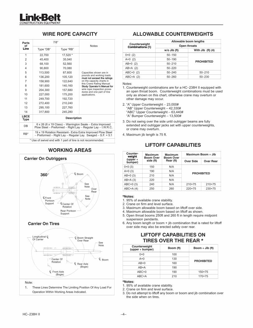
WIRE ROPE CAPACITY
Parts 7/8”of
LineNotes
Line Type “DB” Type “RB”
1 22,700 17,520 *2 45,400 35,0403 68,100 52,5604 90,800 70,0805 113,500 87,600 Capacities shown are in
6 136,200 105,120 pounds and working loadsmust not exceed the ratings
7 158,900 122,640must not exceed the ratingson the capacity charts in
8 181,600 140,160this Crane Rating Manual.Study Operator’s Manual for
9 204,300 157,680Study Operator’s Manual forwire rope inspection proce-
10 227,000 175,200dures and one part of lineapplications.
11 249,700 192,72012 272,400 210,24013 295,100 227,76014 317,800 245,280
LBCEType Description
DB 6 x 26 (6 x 19 Class) – Warrington Seale – Extra ImprovedPlow Steel – Preformed – Right Lay – Regular Lay – I.W.R.C.
RB* 19 x 19 Rotation Resistant– Extra Extra Improved Plow Steel– Preformed – Right Lay – Regular Lay. Swaged – S.F. = 5:1
* Use of swivel end with 1 part of line is not recommended.
WORKING AREAS
BoomCL
FrontPontoonSupport
CL
Center OfRotation
Rear PontoonSupport
CL
Carrier On Outriggers
Longitudinal COf Carrier
L
CL Front Axle(Bogie)
Rear Axle(Bogie)
Center OfRotation
Boom StraightOver Rear
CL
BoomCL
Carrier On Tires
CL
360�
OverRear
SeeNote
SeeNote
SeeNote
Note:�� These Lines Determine The Limiting Position Of Any Load For
Operation Within Working Areas Indicated.
ALLOWABLE COUNTERWEIGHTSAllowable boom lengths
CounterweightCombinations (1) Open throatsCombinations (1)
w/o Jib (ft) With Jib (ft) (4)
0+0 (2) 50–150A+0 (2) 50–190AB+0 (2) 50–210
PROHIBITED
AB+A (2) 50–220ABC+0 (2) 50–240 50–210ABC+A (2) 50–260 50–230
Notes:1. Counterweight combinations are for a HC–238H II equipped with
an open throat boom. Counterweight combinations must be usedonly as shown on this chart, otherwise crane may overturn or other damage may occur.
2. “A” Upper Counterweight – 23,000# “AB” Upper Counterweight – 42,330#“ABC” Upper Counterweight – 63,440# “A” Bumper Counterweight – 13,500#
3. Do not swing over the side until outrigger beams are fullyextended and outrigger jacks set with upper counterweights, or crane may overturn.
4. Maximum jib length is 75 ft.
LIFTOFF CAPABILITIES
Counter-weight
Maximum Maximum Maximum Boom + Jibweight
(upper +bumper)
Boom Overside (ft)
Boom OverRear (ft) Over Side Over Rear
0+0 (3) 150 N/AA+0 (3) 190 N/AAB+0 (3) 210 N/A
PROHIBITED
AB+A (3) 220 N/AABC+0 (3) 240 N/A 210+75 210+75ABC+A (4) 250 260 220+75 230+75
*Notes:1. 95% of available crane stability.2. Crane on firm and level surface.3. Maximum allowable boom based on liftoff over side.4. Maximum allowable boom based on liftoff as shown.5. Open throat booms 250ft and 260 ft in length require midpoint
suspension pendants.6. Any boom length or boom + jib combination that is rated for liftoff
over side may also be erected safely over rear.
LIFTOFF CAPABILITIES ONTIRES OVER THE REAR *
Counterweight(upper + bumper) Boom (ft) Boom + Jib (ft)
0+0 100A+0 130
AB+0 160PROHIBITED
AB+A 190ABC+0 190 150+75ABC+A 210 170+75
*Notes:1. 95% of available crane stability.2. Crane on firm and level surface.3. Do not attempt to liftoff any boom or boom and jib combination over
the side when on tires.

–5– HC–238H II
-�"�%���+,".�%���%,��,$"��-/,.�
+�%","-
1��&�������&&�3��'��3��(���(�����������!�)���&����
�������&����&������'� ��!4�3'��'�3��&(����������)
(�!�����(5�� �(�&)���6�)*
1. The effects of the wind force on the hook load are the respon–
sibility of the user and are not taken into account. When hoisting any load in windy conditions, the load wind area and loadcontrollability must be considered for safe crane operation.
2. Wind speed is to be determined at the boom top section.
+,".��0��.����%�
Boom and Boom + Jib Lengths up to 250’
DESCRIPTIONALLOWABLE
WINDSPEEDS INM.P.H.
1. Normal Lifting Operation.(See Capacity Charts.) 0–20 m.p.h.
2. Reduced Operation.Capacities must be reduced by 20%. 21–30 m.p.h.
3. Reduced Operation.Capacities must be reduced by 40%. 31–40 m.p.h.
4. Reduced Operation.Capacities must be reduced by 70%. 41–45 m.p.h.
4. No Operation.Store Attachment On Ground. Over 45 m.p.h.
Boom and Boom + Jib Lengths greater than 250’1. Normal Lifting Operation.
(See Capacity Charts.) 0–20 m.p.h.
2. Reduced Operation.Capacities must be reduced by 35%. 21–30 m.p.h.
3. Reduced Operation.Capacities must be reduced by 60%. 31–40 m.p.h.
4. Reduced Operation.Capacities must be reduced by 80%. 41–45 m.p.h.
4. No Operation.Store Attachment On Ground. Over 45 m.p.h.
LIVE MAST LIFTING CAPACITIESLoad Radius
(ft)Mast Angle
(deg)On Tires (lbs) On Outriggers
(lbs)
10 71.2 30,000 50,00011 68.9 30,000 50,00012 66.5 30,000 50,00013 64.1 30,000 50,00014 61.6 30,000 50,00015 59.1 30,000 50,00016 56.5 30,000 50,00017 53.8 30,000 50,00018 51.0 29,300 50,00019 48.1 27,200 50,00020 45.1 25,300 50,00021 41.9 23,700 50,00022 38.5 22,200 49,30023 34.8 20,900 45,40024 30.7 19,800 42,10025 26.0 18,700 39,30026 20.5 17,800 36,70027 12.7 16,900 34,500
CAUTION
1. Refer to operator’s manual.2. Live mast backstops must be in position and operative.3. Use rear drum only. Reeve hoist line to drum over mast cross member..4. Reeve hoist rope with three parst of 0.875” diameter wire rope.5. Do not swing upper when crane is on tires and upper equipped with “A”,
“AB”, OR “ABC” counterweights.6. Refer to “crane assembly component weights” for weights of
components when lifting from live mast.
NOTES:1. Refer to the Operator’s Manual.2. The crane shall be leveled on a firm supporting surface.3. Capacities are based on 75% stability.4. See Crane Assembly Component Weights chart for weight of com-
ponents for crane assembly.5. Rated capacities for 360� rotation.6. Boom extensions may be handled with one hook, “A” and “B” coun-
terweights must be handled with two hooks.7. For crane assembly / disassembly only.
A
�%�"����������
�$�0$"�"��+�,-���
WeightComponent
lb
1. 30’ Top Section With 6 Sheave Head Machinery 4,8902. 25’ Top Section with 6 Sheave Head Machinery 4,2423. 10’ Boom Extension With Lifting Sheaves (Non–Luffing Attachment Extension) 2,610
4. 10’ Boom Extension With Lifting Sheaves (Luffing Attachment Extension) 3,370
5. 5’ Hammerhead With Head Machinery 3,5006. 10’ Tapered Hammerhead Extension 1,5007. 5’ Tip Extension Assembly 6408. 20’ Base Section (w/o 3rd Drum) 3,195
� 3rd Drum (w/o Rope) 2,000� 900’ of 0.88” Dia Type RB 990� 3rd Drum Deflector Sheave 430
9. Main Boom Extensions (Includes Boom Pins, Deflector Rollers and Pendants)
� 5 Ft. Open Throat Extension 730� 10 Ft. Extension 970� 20 Ft. Extension 1,540� 30 Ft. Extension 2,120� 40 Ft. Extension 2,680� 50 Ft. Extension 3,240
9 Upper Counterweights� Counterweight “A” 23,000� Counterweight “B” 19,330� Counterweight “C” 21,110� Counterweight “AB” 42,330� Counterweight “ABC” 63,440
10. Bumper Counterweight� Counterweight “A” 13,500
11.Outrigger Box, Beam and Jack Assemblies� Rear Assembly� Front Assembly
9,9508,980
–6–HC–238H II
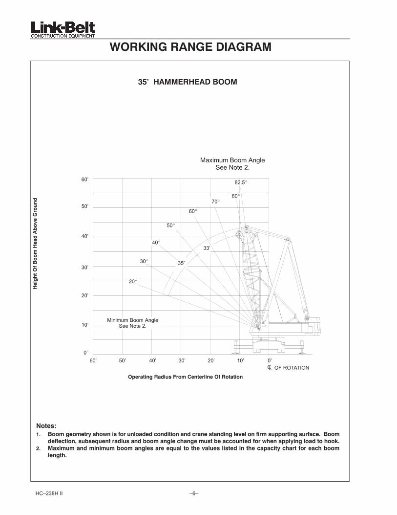
WORKING RANGE DIAGRAM
"���#
�* ���!���!�)��'�3����������&��((����(��������(���������(����& &������!����������������*�����!
(�&�����4��� �7�����(������(� ��!����&��'����!���� ��������(����3'�����&)����&��(����'��8*
9* ����!�!���(�!���!�!� ��!����&����7��&�����'� �&���&���(�����'��������)��'��������'� ��!
&���'*
Hei
gh
t O
f B
oo
m H
ead
Ab
ove
Gro
un
d
:���������%���.��$$�
20’OF ROTATIONCL
Operating Radius From Centerline Of Rotation
10’ 0’30’40’50’
20�
80�
82.5�
0’
60’
30�
40�
60’
50’
40’
30’
20’
Minimum Boom AngleSee Note 2.10’
Maximum Boom AngleSee Note 2.
33’
35’
50�
60�
70�
–7– HC–238H II
‘
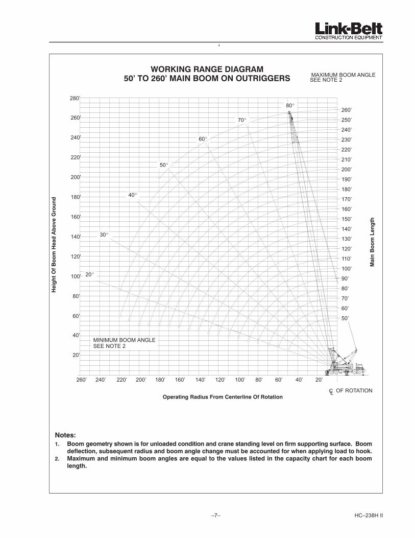
"���#
�* ���!���!�)��'�3����������&��((����(��������(���������(����& &������!����������������*�����!
(�&�����4��� �7�����(������(� ��!����&��'����!���� ��������(����3'�����&)����&��(����'��8*
9* ����!�!���(�!���!�!� ��!����&����7��&�����'� �&���&���(�����'��������)��'��������'� ��!
&���'*
Mai
n B
oo
m L
eng
th
Hei
gh
t O
f B
oo
m H
ead
Ab
ove
Gro
un
d
+$%;,"-�%�"-��.,�-%��
�����$�9<�����,"��$$��$"�$/�%,--�%�
Operating Radius From Centerline Of Rotation OF ROTATION
20’40’60’80’100’120’140’160’180’200’220’240’
50’
60’
70’
80’
90’
100’
110’
120’
130’
140’
150’
160’
170’
180’
190’
200’
210’
220’
230’
240’
250’
260’
60’
80’
120’
140’
160’
180’
200’
220’
240’
260’
20’
40’
260’
MAXIMUM BOOM ANGLESEE NOTE 2
MINIMUM BOOM ANGLESEE NOTE 2
CL
280’80�
70�
60�
50�
40�
30�
20�100’
–8–HC–238H II
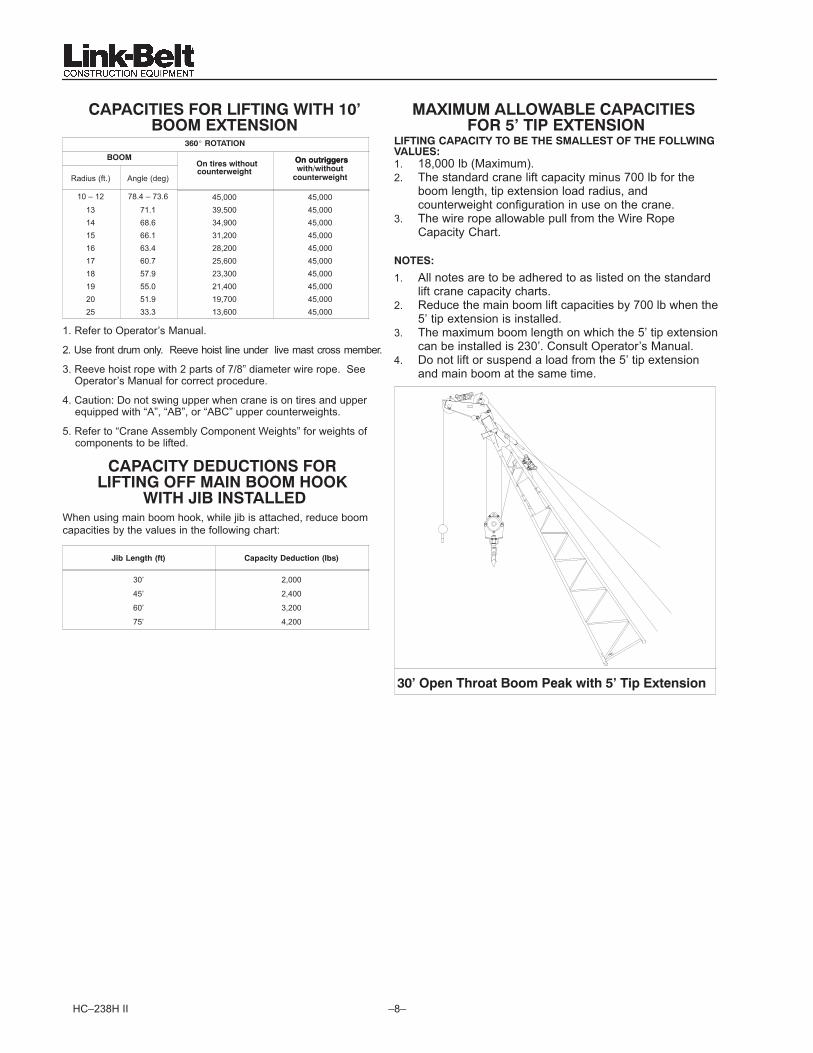
CAPACITIES FOR LIFTING WITH 10’BOOM EXTENSION
360� ROTATION
BOOM On outriggers
Radius (ft.) Angle (deg)
On tires withoutcounterweight
On outriggerswith/without
counterweight
10 – 12 78.4 – 73.6 45,000 45,00013 71.1 39,500 45,00014 68.6 34,900 45,00015 66.1 31,200 45,00016 63.4 28,200 45,00017 60.7 25,600 45,00018 57.9 23,300 45,00019 55.0 21,400 45,00020 51.9 19,700 45,00025 33.3 13,600 45,000
1. Refer to Operator’s Manual.
2. Use front drum only. Reeve hoist line under live mast cross member.
3. Reeve hoist rope with 2 parts of 7/8” diameter wire rope. See Operator’s Manual for correct procedure.
4. Caution: Do not swing upper when crane is on tires and upper equipped with “A”, “AB”, or “ABC” upper counterweights.
5. Refer to “Crane Assembly Component Weights” for weights of components to be lifted.
CAPACITY DEDUCTIONS FOR LIFTING OFF MAIN BOOM HOOK
WITH JIB INSTALLEDWhen using main boom hook, while jib is attached, reduce boomcapacities by the values in the following chart:
Jib Length (ft) Capacity Deduction (lbs)
30’ 2,000
45’ 2,400
60’ 3,200
75’ 4,200
MAXIMUM ALLOWABLE CAPACITIES FOR 5’ TIP EXTENSION
LIFTING CAPACITY TO BE THE SMALLEST OF THE FOLLWINGVALUES:1. 18,000 lb (Maximum).2. The standard crane lift capacity minus 700 lb for the
boom length, tip extension load radius, andcounterweight configuration in use on the crane.
3. The wire rope allowable pull from the Wire RopeCapacity Chart.
NOTES:
1. All notes are to be adhered to as listed on the standardlift crane capacity charts.
2. Reduce the main boom lift capacities by 700 lb when the5’ tip extension is installed.
3. The maximum boom length on which the 5’ tip extensioncan be installed is 230’. Consult Operator’s Manual.
4. Do not lift or suspend a load from the 5’ tip extensionand main boom at the same time.
30’ Open Throat Boom Peak with 5’ Tip Extension

–9– HC–238H II
A BC
A
Main Boom Capacities – On Outriggers – 35 Ft Hammerhead BoomCounterweight Combinations – Upper + Bumper
LoadRadius
BoomAngle 360 Degree Rotation
(ft) (deg)0+0 A+0 AB+0 AB+A ABC+0 ABC+A
10 82.0 300,00011 80.2 267,70012 78.4 250,00013 76.6 237,10014 74.8 221,00015 72.9 206,90016 71.0 194,40017 69.1
PROHIBITED183,300
PROHIBITED
18 67.2 173,30019 65.2 164,30020 63.2 156,20025 52.3 124,60030 39.1 96,30035 17.6 63,900
Main Boom Capacities – On Outriggers – 50 Ft Open Throat Tube Boom
Counterweight Combinations – Upper + BumperLoad
RadiusBoomAngle 360 Degree Rotation
(ft) (deg)ABC+A ABC+0 AB+A AB+0 A+0 0 + 0
12 79.6 264,900 268,700 258,700 261,400 241,100 219,30013 78.4 252,100 255,400 242,600 242,600 223,700 203,40014 77.2 241,000 243,400 226,100 226,100 208,500 189,50015 76.1 228,400 228,400 211,800 211,800 195,200 177,40016 74.9 214,800 214,800 199,100 199,100 183,400 166,70017 73.7 202,700 202,700 187,800 187,800 173,000 157,20018 72.5 191,800 191,800 177,700 177,700 163,700 148,70019 71.3 181,900 181,900 168,500 168,500 155,300 140,90020 70.1 173,000 173,000 160,200 160,200 147,600 131,00025 63.8 138,700 138,700 128,400 128,400 116,600 81,10030 57.3 115,400 115,400 106,800 106,800 84,000 57,90035 50.1 98,600 98,600 88,800 83,300 65,100 44,60040 42.2 85,500 83,500 72,300 67,800 52,700 35,80050 19.8 48,700 48,700 48,700 48,700 37,600 25,000
Main Boom Capacities – On Outriggers – 60 Ft Open Throat Tube Boom
Load BoomCounterweight Combinations – Upper + Bumper
LoadRadius
BoomAngle 360 Degree Rotation
(ft) (deg) ABC+A ABC+0 AB+A AB+0 A+0 0 + 0
13.37 80.0 234,700 234,700 234,700 234,700 217,300 197,60014 79.4 231,700 231,700 225,700 225,700 208,100 189,20015 78.4 225,900 225,900 211,400 211,400 194,900 177,10016 77.4 214,400 214,400 198,800 198,800 183,100 166,40017 76.5 202,300 202,300 187,400 187,400 172,800 157,00018 75.5 191,400 191,400 177,400 177,400 163,400 148,40019 74.5 181,600 181,600 168,300 168,300 155,000 140,70020 73.5 172,800 172,800 160,000 160,000 147,400 131,80025 68.4 138,500 138,500 128,300 128,300 117,100 81,60030 63.2 115,300 115,300 106,700 106,700 84,300 58,30035 57.7 98,500 98,500 89,100 83,600 65,400 44,90040 51.9 84,300 83,800 72,500 68,000 53,000 36,10050 38.4 63,400 60,700 52,300 49,000 37,800 25,20060 18.1 39,900 39,900 39,900 37,700 28,800 18,800
Main Boom Capacities – On Outriggers – 70 Ft Open Throat Tube Boom
Load BoomCounterweight Combinations – Upper + Bumper
LoadRadius
BoomAngle 360 Degree Rotation
(ft) (deg) ABC+A ABC+0 AB+A AB+0 A+0 0 + 0
15.11 80.0 211,100 211,100 210,200 210,200 193,900 176,40016 79.3 207,800 207,800 199,100 199,100 183,500 166,90017 78.4 202,600 202,600 187,800 187,800 173,100 157,40018 77.6 191,700 191,700 177,800 177,800 163,800 148,90019 76.7 181,900 181,900 168,600 168,600 155,400 141,10020 75.9 173,100 173,100 160,300 160,300 147,800 133,90025 71.6 138,800 138,800 128,600 128,600 118,300 82,90030 67.3 115,500 115,500 107,000 107,000 85,300 59,30035 62.8 98,700 98,700 89,800 84,300 66,100 45,50040 58.0 86,000 84,400 73,100 68,600 53,600 36,70050 47.8 64,500 61,100 52,800 49,400 38,300 25,70060 35.4 50,000 47,300 40,800 38,100 29,200 19,30070 16.7 40,300 38,200 32,700 30,500 23,100 14,800
Main Boom Capacities – On Outriggers – 80 Ft Open Throat Tube Boom
Load BoomCounterweight Combinations – Upper + Bumper
LoadRadius
BoomAngle 360 Degree Rotation
(ft) (deg) ABC+A ABC+0 AB+A AB+0 A+0 0 + 0
16.84 80.0 189,100 189,100 188,900 188,900 174,200 158,20017 79.9 188,500 188,500 187,200 187,200 172,600 156,90018 79.2 185,600 185,600 177,200 177,200 163,300 148,40019 78.4 181,300 181,300 168,100 168,100 155,000 140,70020 77.7 172,600 172,600 159,800 159,900 147,300 133,80025 74.0 138,400 138,400 128,200 128,200 117,900 83,10030 70.2 115,200 115,200 106,600 106,600 85,400 59,40035 66.4 98,400 98,400 89,800 84,300 66,200 45,60040 62.4 85,700 84,300 73,100 68,600 53,600 36,70050 54.0 64,400 61,100 52,700 49,400 38,300 25,70060 44.5 49,900 47,300 40,700 38,100 29,200 19,20070 33.1 40,400 38,200 32,700 30,500 23,100 14,90080 15.6 33,600 31,700 27,000 25,100 18,900 11,800
Main Boom Capacities – On Outriggers – 90 Ft Open Throat Tube Boom
Load BoomCounterweight Combinations – Upper + Bumper
LoadRadius
BoomAngle 360 Degree Rotation
(ft) (deg) ABC+A ABC+0 AB+A AB+0 A+0 0 + 0
18.58 80.0 170,000 170,000 170,000 170,000 157,800 143,300
19 79.7 168,900 168,900 167,500 167,500 154,400 140,200
20 79.1 166,300 166,300 159,300 159,300 146,800 133,400
25 75.8 138,000 137,900 127,800 127,800 117,500 83,200
30 72.5 114,800 114,800 106,200 106,200 85,400 59,400
35 69.1 98,000 98,000 89,800 84,300 66,100 45,500
40 65.7 85,400 84,300 73,000 68,500 53,500 36,600
50 58.5 64,300 61,000 52,600 49,300 38,200 25,600
60 50.7 49,800 47,100 40,600 38,000 29,100 19,200
70 41.8 40,300 38,100 32,600 30,400 23,100 14,800
80 31.1 33,500 31,600 26,900 25,100 18,800 11,700
90 14.7 28,400 26,800 22,700 21,100 15,600 9,400
Note: Refer To Page 8 For “Capacity Deductions” Caused By Any Jib Attachment Or Tip Extension.

–10–HC–238H II
A BC
A
Main Boom Capacities – On Outriggers – 100 Ft Open Throat Tube Boom
Load BoomCounterweight Combinations – Upper + Bumper
LoadRadius
BoomAngle 360 Degree Rotation
(ft) (deg) ABC+A ABC+0 AB+A AB+0 A+0 0 + 0
20.32 80.0 153,300 153,300 153,300 153,300 144,000 129,70025 77.3 137,400 137,400 127,300 127,300 117,100 83,20030 74.3 114,300 114,300 105,800 105,800 85,300 59,30035 71.3 97,600 97,600 89,700 84,200 66,100 45,50040 68.3 85,000 84,100 72,900 68,300 53,400 36,50050 61.9 64,200 60,800 52,500 49,100 38,100 25,50060 55.2 49,700 47,000 40,500 37,800 28,900 19,00070 47.9 40,200 38,000 32,500 30,300 22,900 14,70080 39.6 33,400 31,500 26,800 24,900 18,700 11,60090 29.5 28,300 26,700 22,600 21,000 15,500 9,300
100 14.0 24,300 22,900 19,300 17,800 12,900 7,400
Main Boom Capacities – On Outriggers – 110 Ft Open Throat Tube Boom
Load BoomCounterweight Combinations – Upper + Bumper
LoadRadius
BoomAngle 360 Degree Rotation
(ft) (deg) ABC+A ABC+0 AB+A AB+0 A+0 0 + 0
22.05 80.0 139,600 139,600 139,600 139,600 132,300 107,90025 78.4 134,000 134,000 126,800 126,800 116,600 83,30030 75.8 113,900 113,900 105,400 105,400 85,200 59,30035 73.1 97,200 97,200 89,500 84,000 65,900 45,40040 70.3 84,600 84,000 72,700 68,200 53,300 36,40050 64.7 64,000 60,600 52,300 48,900 37,900 25,30060 58.8 49,500 46,800 40,300 37,600 28,800 18,90070 52.4 40,000 37,800 32,300 30,100 22,700 14,50080 45.5 33,200 31,300 26,600 24,700 18,500 11,50090 37.7 28,100 26,500 22,500 20,800 15,300 9,100
100 28.1 24,200 22,700 19,200 17,700 12,800 7,300110 13.3 21,100 19,700 16,500 15,200 10,800 5,800
Main Boom Capacities – On Outriggers – 120 Ft Open Throat Tube Boom
Load BoomCounterweight Combinations – Upper + Bumper
LoadRadius
BoomAngle 360 Degree Rotation
(ft) (deg) ABC+A ABC+0 AB+A AB+0 A+0 0 + 0
23.79 80.0 126,700 126,700 126,700 126,700 122,100 91,90025 79.4 125,100 125,100 125,100 125,100 116,100 83,30030 77.0 113,400 113,400 104,900 104,900 85,200 59,20035 74.5 96,800 96,800 89,400 83,900 65,800 45,20040 72.0 84,200 83,800 72,600 68,000 53,100 36,30050 66.9 63,800 60,400 52,100 48,700 37,700 25,10060 61.6 49,200 46,600 40,100 37,400 28,600 18,70070 56.0 39,800 37,600 32,100 29,900 22,500 14,30080 50.1 33,000 31,100 26,400 24,500 18,400 11,30090 43.5 27,900 26,300 22,300 20,600 15,100 8,900
100 36.0 24,000 22,500 19,000 17,500 12,600 7,100110 26.9 20,900 19,600 16,300 15,000 10,600 5,700120 12.7 18,300 17,100 14,100 12,900 9,000 4,500
Main Boom Capacities – On Outriggers – 130 Ft Open Throat Tube Boom
Load BoomCounterweight Combinations – Upper + Bumper
LoadRadius
BoomAngle 360 Degree Rotation
(ft) (deg) ABC+A ABC+0 AB+A AB+0 A+0 0 + 0
25.53 80.0 116,000 116,000 116,000 116,000 113,100 79,90030 78.0 110,200 110,200 104,500 104,500 85,000 59,10035 75.7 96,300 96,300 89,100 83,800 65,700 45,10040 73.4 83,800 83,600 72,400 67,800 52,900 36,10050 68.8 63,600 60,200 51,900 48,500 37,500 24,90060 64.0 49,000 46,300 39,900 37,200 28,300 18,50070 59.0 39,600 37,400 31,900 29,600 22,500 14,10080 53.7 32,800 30,900 26,200 24,300 18,100 11,00090 48.0 27,700 26,000 22,100 20,400 14,900 8,700
100 41.7 23,700 22,400 18,800 17,300 12,400 6,900110 34.6 20,700 19,400 16,100 14,800 10,400 5,500120 25.8 18,100 16,900 14,000 12,800 8,800 4,300130 12.2 15,900 14,800 12,100 11,000 7,400 3,300
Main Boom Capacities – On Outriggers – 140 Ft Open Throat Tube Boom
Load BoomCounterweight Combinations – Upper + Bumper
LoadRadius
BoomAngle 360 Degree Rotation
(ft) (deg) ABC+A ABC+0 AB+A AB+0 A+0 0 + 0
27.26 80.0 105,500 105,500 105,500 105,500 100,700 70,30030 78.9 102,900 102,900 102,900 102,900 84,900 59,00035 76.8 95,900 95,800 88,600 83,600 65,500 44,90040 74.7 83,300 83,300 72,200 67,600 52,800 36,00050 70.4 63,400 60,000 51,700 48,300 37,300 24,70060 66.0 48,800 46,100 39,700 37,000 28,100 18,30070 61.4 39,300 37,100 31,600 29,400 22,200 13,90080 56.6 32,500 30,600 25,900 24,000 17,900 10,80090 51.6 27,400 25,800 21,800 20,200 14,700 8,500
100 46.1 23,500 22,200 18,500 17,100 12,200 6,700110 40.1 20,500 19,200 15,900 14,600 10,200 5,300120 33.3 17,900 16,700 13,700 12,500 8,600 4,100130 24.8 15,700 14,700 11,900 10,800 7,200 3,100140 11.8 13,900 12,900 10,400 9,400 6,000 2,200
Main Boom Capacities – On Outriggers – 150 Ft Open Throat Tube Boom
Load BoomCounterweight Combinations – Upper + Bumper
LoadRadius
BoomAngle 360 Degree Rotation
(ft) (deg) ABC+A ABC+0 AB+A AB+0 A+0 0 + 0
29 80.0 96,800 96,800 96,800 96,800 89,800 62,70030 79.6 95,900 95,900 95,900 95,900 84,800 58,90035 77.7 91,700 91,700 88,200 83,400 65,400 44,80040 75.7 82,900 82,900 72,000 67,400 52,600 35,80050 71.7 63,200 59,800 51,500 48,100 37,100 24,50060 67.6 48,500 45,900 39,400 36,800 27,900 18,10070 63.4 39,100 36,900 31,400 29,200 22,000 13,70080 59.1 32,300 30,400 25,700 23,800 17,700 10,60090 54.5 27,200 25,500 21,600 19,900 14,500 8,300
100 49.7 23,200 21,900 18,300 16,800 12,000 6,500110 44.5 20,200 18,900 15,700 14,300 10,000 5,000120 38.7 17,700 16,500 13,500 12,300 8,300 3,800130 32.1 15,500 14,400 11,700 10,600 7,000 2,900140 24.0 13,700 12,700 10,200 9,200 5,800 2,000150 11.4 12,100 11,200 8,800 7,900 4,800 –––
Note: Refer To Page 8 For “Capacity Deductions” Caused By Any Jib Attachment Or Tip Extension.

–11– HC–238H II
A BC
A
Main Boom Capacities – On Outriggers – 160 Ft Open Throat Tube Boom
Load BoomCounterweight Combinations – Upper + Bumper
LoadRadius
BoomAngle 360 Degree Rotation
(ft) (deg) ABC+A ABC+0 AB+A AB+0 A+0 0 + 0
30.74 80.0 88,100 88,100 88,100 88,100 81,10035 78.4 85,100 85,100 85,100 83,200 65,20040 76.6 81,400 81,400 71,800 67,200 52,40050 72.9 62,900 59,600 51,200 47,900 36,90060 69.1 48,300 45,600 39,200 36,500 27,70070 65.2 38,800 36,600 31,100 28,900 21,80080 61.2 32,000 30,100 25,400 23,500 17,40090 57.0 26,900 25,300 21,400 19,700 14,200 T
ED
100 52.7 23,000 21,700 18,000 16,600 11,700 IBIT
110 48.0 20,000 18,700 15,400 14,100 9,700 OH
I120 43.0 17,400 16,200 13,200 12,000 8,100 P
R130 37.4 15,300 14,200 11,400 10,400 6,700140 31.1 13,400 12,400 9,900 8,900 5,600150 23.2 11,900 10,900 8,600 7,700 4,600160 11.0 10,500 9,600 7,500 6,600 3,700
Main Boom Capacities – On Outriggers – 170 Ft Open Throat Tube Boom
Load BoomCounterweight Combinations – Upper + Bumper
LoadRadius
BoomAngle 360 Degree Rotation
(ft) (deg) ABC+A ABC+0 AB+A AB+0 A+0 0 + 0
32.47 80.0 81,000 81,000 81,000 81,000 73,60035 79.1 79,200 79,200 79,200 79,200 65,00040 77.4 76,100 76,100 71,500 67,300 52,20050 73.9 62,700 59,300 51,000 47,600 36,70060 70.4 48,000 45,400 39,000 36,300 27,40070 66.8 38,600 36,400 30,900 28,700 21,50080 63.0 31,700 29,800 25,200 23,300 17,200 E
D
90 59.2 26,600 25,000 21,100 19,400 14,000 BIT
E
100 55.2 22,700 21,400 17,800 16,300 11,400 HIB
110 51.0 19,700 18,400 15,100 13,800 9,400 PR
O
120 46.5 17,100 15,900 13,000 11,800 7,800
P
130 41.6 15,000 13,900 11,200 10,100 6,400140 36.3 13,200 12,200 9,700 8,700 5,300150 30.1 11,600 10,700 8,400 7,400 4,300160 22.5 10,300 9,400 7,200 6,400 3,400170 10.7 9,100 8,300 6,200 5,400 2,700
Main Boom Capacities – On Outriggers – 180 Ft Open Throat Tube Boom
Load BoomCounterweight Combinations – Upper + Bumper
LoadRadius
BoomAngle 360 Degree Rotation
(ft) (deg) ABC+A ABC+0 AB+A AB+0 A+0 0 + 0
34.21 80.0 72,100 72,100 72,100 72,100 67,20035 79.7 72,100 72,100 72,100 72,100 64,90040 78.1 71,000 71,000 71,000 67,100 52,00050 74.8 62,400 59,100 50,700 47,400 36,50060 71.5 47,800 45,100 38,700 36,000 27,20070 68.1 38,300 36,100 30,600 28,400 21,30080 64.7 31,500 29,600 24,900 23,000 16,900 D
90 61.1 26,400 24,700 20,800 19,200 13,700 ITE
D
100 57.4 22,400 21,200 17,500 16,100 11,200 IBIT
110 53.5 19,500 18,100 14,900 13,600 9,200 RO
H
120 49.4 16,900 15,700 12,700 11,500 7,500 PR
130 45.1 14,700 13,600 10,900 9,800 6,200140 40.4 12,900 11,900 9,400 8,400 5,000150 35.2 11,400 10,400 8,100 7,200 4,000160 29.3 10,000 9,100 7,000 6,100 3,200170 21.9 8,800 8,000 6,000 5,200 2,400180 10.4 7,800 7,000 5,100 4,300 –––
Main Boom Capacities – On Outriggers – 190 Ft Open Throat Tube Boom
Load BoomCounterweight Combinations – Upper + Bumper
LoadRadius
BoomAngle 360 Degree Rotation
(ft) (deg) ABC+A ABC+0 AB+A AB+0 A+0 0 + 0
35.95 80.0 63,300 63,300 63,300 63,300 61,80040 78.8 62,500 62,500 62,500 62,500 51,80050 75.7 59,800 58,800 50,500 47,100 36,20060 72.5 47,500 44,800 38,500 35,800 26,90070 69.3 38,100 35,900 30,400 28,100 21,00080 66.1 31,200 29,300 24,600 22,700 16,70090 62.7 26,100 24,400 20,600 18,900 13,400 D
100 59.3 22,400 20,900 17,300 15,800 10,900 ITE
D
110 55.7 19,200 17,900 14,600 13,300 8,900 IBIT
120 52.0 16,600 15,400 12,400 11,200 7,300 RO
H
130 48.0 14,500 13,400 10,600 9,500 5,900 PR
140 43.8 12,600 11,600 9,100 8,100 4,700150 39.3 11,100 10,100 7,800 6,900 3,800160 34.3 9,700 8,900 6,700 5,800 2,900170 28.5 8,600 7,700 5,700 4,900 2,200180 21.3 7,500 6,700 4,800 4,100 –––
190 10.1 6,500 5,900 4,100 3,300 –––
Note: Refer To Page 8 For “Capacity Deductions” Caused By Any Jib Attachment Or Tip Extension.

–12–HC–238H II
A BC
A
Main Boom Capacities – On Outriggers – 200 Ft Open Throat Tube Boom
Load BoomCounterweight Combinations – Upper + Bumper
LoadRadius
BoomAngle 360 Degree Rotation
(ft) (deg) ABC+A ABC+0 AB+A AB+0 A+0 0 + 0
37.68 80.0 56,000 56,000 56,000 56,00040 79.3 55,300 55,300 55,300 55,30050 76.4 53,200 53,200 50,300 46,90060 73.4 47,200 44,600 38,200 35,50070 70.4 37,800 35,600 30,100 27,90080 67.3 30,900 29,000 24,300 22,40090 64.2 25,800 24,100 20,300 18,700
100 61.0 22,100 20,600 17,000 15,500110 57.6 18,900 17,600 14,300 13,000120 54.2 16,300 15,100 12,200 11,000
PROHIBITED
130 50.6 14,200 13,100 10,400 9,300140 46.7 12,400 11,300 8,800 7,800150 42.7 10,800 9,900 7,500 6,600160 38.3 9,500 8,600 6,400 5,500170 33.4 8,300 7,500 5,400 4,600180 27.7 7,200 6,500 4,600 3,800190 20.7 6,300 5,600 3,800 3,100200 9.9 5,200 4,800 3,100 2,400
Main Boom Capacities – On Outriggers – 210 Ft Open Throat Tube Boom
Load BoomCounterweight Combinations – Upper + Bumper
LoadRadius
BoomAngle 360 Degree Rotation
(ft) (deg) ABC+A ABC+0 AB+A AB+0 A+0 0 + 0
!�"# $��� "!�%�� "!�%�� "!�%�� "!�%��
"� &!�$ "!�%�� "!�%�� "!�%�� "!�%��
%� &&�� "&� �� "&� �� "&� �� "'�'��
'� &"�# "#� �� "#� �� $���� %� ��
&� &��" &�%�� %� �� #!�$�� #&�'��
$� '$�% ��'�� #$�$�� #"���� ##�#��
!� '%�% #%�%�� # �!�� #����� �$�"��
��� '#�% #��$�� #�� �� �'�&�� �%�#��
��� %!�" �$�'�� �&� �� �"���� �#�&��
�#� %'�� �'���� �"�$�� ���!�� ���&�� PROHIBITED
� � %#�$ � �!�� �#�$�� ������ !����
�"� "!� �#���� ������ $�'�� &�%��
�%� "%�' ���%�� !�'�� &�#�� '� ��
�'� "��' !�#�� $� �� '���� %�#��
�&� &� $���� &�#�� %���� "� ��
�$� #�% '�!�� '�#�� "� �� �%��
�!� #&�� '���� %� �� �%�� #�$��
#�� #��# %�#�� "�%�� #�$�� #����
#�� !�' "���� �$�� #�#�� (((
Main Boom Capacities – On Outriggers – 220 Ft Open Throat Tube Boom
Load BoomCounterweight Combinations – Upper + Bumper
LoadRadius
BoomAngle 360 Degree Rotation
(ft) (deg) ABC+A ABC+0 AB+A AB+0 A+0 0 + 0
41.16 80.0 43,500 43,500 43,50050 77.7 41,600 41,600 41,60060 75.0 37,700 37,700 37,70070 72.3 33,900 33,900 29,60080 69.5 30,400 28,500 23,80090 66.7 25,200 23,600 19,800
100 63.8 21,500 20,100 16,400110 60.9 18,400 17,000 13,800120 57.9 15,800 14,600 11,600130 54.7 13,600 12,500 9,800 PROHIBITED
140 51.5 11,800 10,800 8,300150 48.1 10,200 9,300 7,000160 44.5 8,900 8,000 5,800170 40.6 7,700 6,900 4,800180 36.4 6,700 5,900 4,000190 31.8 5,700 5,000 3,200200 26.4 4,900 4,200 2,500210 19.8 4,200 3,500 –––––
220 9.4 3,000 2,900 –––––
Main Boom Capacities – On Outriggers – 230 Ft Open Throat Tube Boom
Load BoomCounterweight Combinations – Upper + Bumper
LoadRadius
BoomAngle 360 Degree Rotation
(ft) (deg) ABC+A ABC+0 AB+A AB+0 A+0 0 + 0
42.89 80.0 38,700 38,70050 78.2 37,200 37,20060 75.6 33,700 33,70070 73.1 30,300 30,30080 70.4 27,300 27,30090 67.8 24,300 23,300
100 65.0 20,100 19,800110 62.3 17,400 16,800120 59.4 15,100 14,300130 56.5 13,100 12,200 PROHIBITED
140 53.4 11,300 10,500150 50.3 9,700 9,000160 46.9 8,300 7,700170 43.4 7,100 6,600180 39.7 6,000 5,600190 35.6 5,000 4,700200 31.0 4,100 3,900210 25.8 3,200 3,200220 19.3 2,500 2,500
Note: Refer To Page 8 For “Capacity Deductions” Caused By Any Jib Attachment Or Tip Extension.

–13– HC–238H II
A BC
A
Main Boom Capacities – On Outriggers – 240 Ft Open Throat Tube Boom
Load BoomCounterweight Combinations – Upper + Bumper
LoadRadius
BoomAngle 360 Degree Rotation
(ft) (deg) ABC+A ABC+0 AB+A AB+0 A+0 0 + 0
44.63 80.0 34,600 34,60050 78.7 33,500 33,50060 76.2 30,100 30,10070 73.8 27,100 27,10080 71.3 24,400 24,40090 68.7 21,000 21,000
100 66.1 18,200 18,200110 63.5 15,700 15,700120 60.8 13,500 13,500130 58.0 11,600 11,600
PROHIBITED
140 55.2 9,900 9,900150 52.2 8,400 8,400160 49.1 7,100 7,100170 45.9 5,900 5,900180 42.5 4,900 4,900190 38.8 3,900 3,900200 34.8 3,100 3,100210 30.4 2,300 2,300
Main Boom Capacities – On Outriggers – 250 Ft Open Throat Tube Boom
Load BoomCounterweight Combinations – Upper + Bumper
LoadRadius
BoomAngle 360 Degree Rotation
(ft) (deg) ABC+A ABC+0 AB+A AB+0 A+0 0 + 0
46.37 80.0 30,90050 79.2 30,10060 76.8 27,10070 74.4 24,40080 72.0 21,20090 69.6 18,500
100 67.2 15,900110 64.6 13,500120 62.1 11,500
PROHIBITED
130 59.5 9,700140 56.8 8,100150 54.0 6,700160 51.1 5,500170 48.1 4,400180 44.9 3,400190 41.6 2,600
Main Boom Capacities – On Outriggers – 260 Ft Open Throat Tube Boom
Load BoomCounterweight Combinations – Upper + Bumper
LoadRadius
BoomAngle 360 Degree Rotation
(ft) (deg) ABC+A ABC+0 AB+A AB+0 A+0 0 + 0
48.1 80.0 27,50050 79.6 27,00060 77.3 24,30070 75.1 21,10080 72.8 19,00090 70.4 16,800
100 68.1 14,200110 65.7 12,000 PROHIBITED
120 63.2 10,100130 60.7 8,400140 58.2 6,900150 55.6 5,600160 52.8 4,500170 50.0 3,400180 47.1 2,500
Note: Refer To Page 8 For “Capacity Deductions” Caused By Any Jib Attachment Or Tip Extension.

–14–HC–238H II
This page intentionally blank

–15– HC–238H II
This page intentionally blank

–16–HC–238H II
���8=�&���������������7���!�����!���)� � �����)���* ����+� ,,,����+- ����).� Link–Belt is a registered trademark. Copyright 2005. All rights reserved. We are constantly improving our products and therefore reserve the right to change designs and specifications.
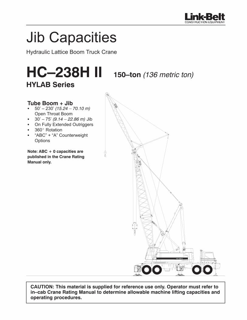
Jib CapacitiesHydraulic Lattice Boom Truck Crane
HC–238H II 150–ton (136 metric ton)���������
HC–238H II
Tube Boom + Jib� 50’ – 230’ (15.24 – 70.10 m)
Open Throat Boom� 30’ – 75’ (9.14 – 22.86 m) Jib� On Fully Extended Outriggers� 360� Rotation� “ABC” + “A” Counterweight
Options
"��#�����>���������������
�� &��'(�����'�����%�����
�����&���&)*
CAUTION: This material is supplied for reference use only. Operator must refer toin–cab Crane Rating Manual to determine allowable machine lifting capacities andoperating procedures.

HC–238H II
TUBULAR JIB NOTES FOR OPEN THROAT BOOM1. Capacities are for a HC – 238H II Truck Crane with “ABC + 0” (63,440 lb + 0) and “ ABC+A” (63,440 lb + 13,500
lb) Counterweight. Verify crane counterweight configuration and consult proper jib capacity chart prior to liftingloads.
2. Capacities are for Truck Crane working areas for 360�, described on the working area chart found in theGeneral Information Section of the Crane Rating Manual and are based on crane standing level on outriggerson firm supporting surface.
3. Capacities are limited to a LBCE 62” x 70” tubular boom with an open throat and a LBCE 24” x 32” cross–sectionjib with jib mast properly assembled.
4. Two parts of 7/8” Diameter Type “N”, Type “DB”, or Type “RB” wire rope are required for maximum lift.
5. Capacities are for 30’, 45’, 60’, and 75’ jib lengths only.
6. A jib cannot be used on open throat boom lengths longer than 230’.
7. The least stable condition is over the side.
8. All capacities are in pounds and are not more than 85% of the tipping loads. Those capacities in the shadedareas are governed by factors other than those that would cause a tipping condition.
9. A deduction must be made from the jib capacities for the weight of the following: Main boom hook block or hookball, jib hook block or hook ball, slings, grapple, load weighing devices, etc.
A BC
A
�����/�����)��� �, ��0������)�
5�
25� 15�
1�-����2�-����� ������ �3���.

HC–238H II
WORKING RANGE DIAGRAM
�����$�9:���$0�"���%$����$$��+,���:��=?���@,�
"���#
�* ���!���!�)��'�3����������&��((����(��������(���������(����& &������!����������
�����*�����!�(�&�����4��� �7�����(���4���(� ��!����&��'����!���� ��������(���
3'�����&)����&��(����'��8*
9* ����!�!���(�!���!�!� ��!����&����7��&�����'� �&���&���(�����'��������)��'��������'
��!�&���'*
Hei
gh
t O
f B
oo
m A
bo
ve G
rou
nd
Mai
n B
oo
m L
eng
thM
ain
Bo
om
+ J
ib L
eng
th
����4�1�15�6
#�7"�7'�7$�7���7�#�7�"�7�'�7�$�7#��7##�7#"�7
�8�4�1569�4�35:;��4�<�����4�1�15�6
%�7
'�7
&�7
$�7
!�7
���7
���7
�#�7
� �7
�"�7
�%�7
�'�7
�&�7
�$�7
�!�7
#��7
#��7
##�7
# �7
'�7
$�7
���7
�#�7
�"�7
�'�7
�$�7
#��7
##�7
#"�7
#'�7
#�7
"�7
#'�7 ��7 #$�7
#$�7
��7
# �7�/�&%7
# �7�/�'�7
# �7�/�"%7
# �7�/� �7
<565<:<����<��69��;���6�1��#
#�7
#%��%�
%�
$��
&��
'��
%��
"��
��
�
MAXIMUM BOOMANGLE SEE NOTE 2
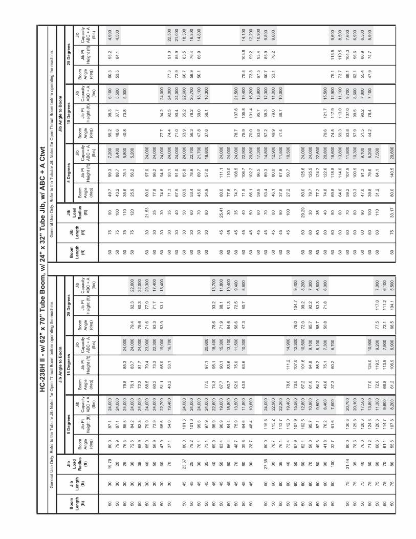
5030
19.7
980
.087
.124
,000
5075
9049
.799
.37,
200
55.2
98.3
6,10
060
.395
.24,
900
5030
2079
.987
.124
,000
5075
100
43.2
88.7
6,40
048
.687
.75,
500
53.5
84.1
4,50
0
5030
2576
.385
.824
,000
79.8
85.3
24,0
0050
7511
035
.675
.15,
800
40.8
73.8
5,00
0
5030
3072
.684
.224
,000
76.1
83.7
24,0
0079
.482
.322
,600
5075
120
25.9
56.2
5,20
0
5030
3568
.982
.324
,000
72.3
81.7
24,0
0075
.680
.322
,000
5030
4065
.079
.924
,000
68.5
79.4
23,9
0071
.677
.920
,300
6030
21.5
380
.097
.024
,000
5030
5056
.973
.924
,000
60.2
73.3
22,3
0063
.371
.717
,400
6030
2577
.896
.224
,000
5030
6047
.965
.622
,700
51.1
65.0
19,0
0053
.963
.115
,400
6030
3074
.694
.824
,000
77.7
94.2
24,0
00
5030
7037
.154
.019
,400
40.2
53.1
16,7
0060
3035
71.3
93.1
24,0
0074
.492
.524
,000
77.3
91.0
22,5
00
6030
4067
.991
.024
,000
71.0
90.4
24,0
0073
.988
.921
,000
5045
23.6
780
.010
1.3
24,0
0060
3050
60.9
85.8
24,0
0063
.985
.222
,600
66.7
83.5
18,3
00
5045
2579
.210
1.0
24,0
0060
3060
53.4
78.9
22,7
0056
.378
.220
,700
58.9
76.4
16,3
00
5045
3076
.199
.624
,000
6030
7045
.069
.721
,700
47.8
69.0
18,1
0050
.166
.914
,800
5045
3573
.197
.924
,000
77.5
97.1
20,6
0060
3080
34.9
57.0
18,8
0037
.656
.116
,300
5045
4069
.995
.922
,600
74.3
95.1
18,4
0078
.693
.213
,700
5045
5063
.490
.919
,000
67.7
90.1
15,3
0071
.988
.111
,800
6045
25.4
180
.011
1.1
24,0
00
5045
6056
.484
.415
,800
60.7
83.6
13,1
0064
.681
.310
,400
6045
3077
.511
0.0
24,0
00
5045
7048
.775
.913
,500
52.9
75.0
11,5
0056
.672
.59,
400
6045
3574
.710
8.5
24,0
0078
.710
7.6
21,5
00
5045
8039
.864
.611
,800
43.9
63.6
10,3
0047
.360
.78,
600
6045
4071
.910
6.7
22,9
0075
.910
5.8
19,4
0079
.810
3.8
14,1
00
5045
9028
.748
.410
,600
6045
5066
.110
2.2
20,8
0070
.010
1.4
16,2
0073
.899
.212
,200
6045
6059
.996
.517
,300
63.8
95.7
13,9
0067
.593
.410
,900
5060
27.5
580
.011
5.8
24,0
0060
4570
53.4
89.3
14,8
0057
.288
.312
,300
60.7
85.9
9,80
0
5060
3078
.711
5.2
22,9
0060
4580
46.1
80.0
12,9
0049
.979
.011
,000
53.1
76.2
9,00
0
5060
3576
.111
3.7
22,2
0060
4590
37.8
67.9
11,5
0041
.466
.710
,000
5060
4073
.411
2.0
19,4
0078
.611
1.2
14,9
0060
4510
027
.250
.710
,500
5060
5067
.910
7.9
15,5
0073
.010
7.0
12,3
0078
.010
4.7
9,40
0
5060
6062
.110
2.5
12,8
0067
.210
1.6
10,5
0072
.099
.28,
200
6060
29.2
980
.012
5.6
24,0
00
5060
7056
.095
.710
,900
61.0
94.8
9,10
065
.792
.27,
300
6060
3079
.712
5.5
24,0
00
5060
8049
.387
.19,
500
54.2
86.2
8,10
058
.783
.36,
600
6060
3577
.212
4.2
22,6
00
5060
9041
.876
.28,
400
46.6
75.1
7,30
050
.871
.86,
000
6060
4074
.812
2.6
20,8
0079
.612
1.7
15,5
00
5060
100
32.7
61.6
7,60
037
.360
.26,
700
6060
5069
.811
8.8
16,6
0074
.511
7.9
12,9
0079
.111
5.5
9,60
0
6060
6064
.611
4.0
13,8
0069
.311
3.0
11,1
0073
.711
0.5
8,50
0
5075
31.4
480
.013
0.6
20,7
0060
6070
59.2
107.
911
,800
63.8
107.
09,
700
68.1
104.
37,
600
5075
3578
.312
9.8
20,1
0060
6080
53.3
100.
510
,300
57.9
99.5
8,60
062
.196
.66,
900
5075
4076
.012
8.3
17,5
0060
6090
47.0
91.3
9,10
051
.590
.27,
800
55.4
86.9
6,30
0
5075
5071
.212
4.8
13,8
0077
.012
4.0
10,9
0060
6010
039
.879
.68,
200
44.2
78.4
7,10
047
.974
.75,
900
5075
6066
.312
0.3
11,3
0072
.011
9.5
9,20
077
.511
7.0
7,00
060
6011
031
.264
.17,
500
5075
7061
.111
4.7
9,60
066
.811
3.9
7,90
072
.111
1.2
6,10
0
5075
8055
.610
7.8
8,20
061
.210
6.9
6,90
066
.510
4.1
5,50
060
7533
.17
80.0
140.
520
,600
Boom
Ang
le(d
eg)
Jib
Pt
Hei
ght (
ft)
Boom
Ang
le(d
eg)
Jib
Pt
Hei
ght (
ft)Ji
b P
t H
eigh
t (ft)
Jib
Pt
Hei
ght (
ft)Ji
b P
t H
eigh
t (ft)
Boo
mLe
ngth
(ft)
Jib
Leng
th(ft
)
Jib
Load
Rad
ius
(ft)
Boom
Ang
le(d
eg)
Boom
Ang
le(d
eg)
Boom
Ang
le(d
eg)
HC
-238
H II
- w
/ 62"
x 7
0" T
ube
Boo
m, w
/ 24"
x 3
2" T
ube
Jib,
w/ A
BC
+ A
Ctw
t
25 D
egre
es15
Deg
rees
5 D
egre
es5
Deg
rees
15 D
egre
es25
Deg
rees
Jib
Ang
le to
Boo
m
Jib
Cap
acity
ABC
+ A
(lb
s)
Jib
Cap
acity
ABC
+ A
(lb
s)
Jib
Cap
acity
ABC
+ A
(lb
s)
Jib
Pt
Hei
ght (
ft)
Gen
eral
Use
Onl
y. R
efer
to th
e Tu
bula
r Jib
Not
es fo
r Ope
n Th
roat
Boo
m b
efor
e op
erat
ing
the
mac
hine
.
Boom
Ang
le(d
eg)
Boo
mLe
ngth
(ft)
Jib
Leng
th(ft
)
Jib
Load
Rad
ius
(ft)
Gen
eral
Use
Onl
y. R
efer
to th
e Tu
bula
r Jib
Not
es fo
r Ope
n Th
roat
Boo
m b
efor
e op
erat
ing
the
mac
hine
.
Jib
Ang
le to
Boo
m
Jib
Cap
acity
ABC
+ A
(lb
s)
Jib
Cap
acity
ABC
+ A
(lb
s)
Jib
Cap
acity
ABC
+ A
(lb
s)

Boom
Ang
le(d
eg)
Jib
Pt
Hei
ght (
ft)
Boom
Ang
le(d
eg)
Jib
Pt
Hei
ght (
ft)Ji
b P
t H
eigh
t (ft)
Jib
Pt
Hei
ght (
ft)Ji
b P
t H
eigh
t (ft)
Boo
mLe
ngth
(ft)
Jib
Leng
th(ft
)
Jib
Load
Rad
ius
(ft)
Boom
Ang
le(d
eg)
Boom
Ang
le(d
eg)
Boom
Ang
le(d
eg)
HC
-238
H II
- w
/ 62"
x 7
0" T
ube
Boo
m, w
/ 24"
x 3
2" T
ube
Jib,
w/ A
BC
+ A
Ctw
t
25 D
egre
es15
Deg
rees
5 D
egre
es5
Deg
rees
15 D
egre
es25
Deg
rees
Jib
Ang
le to
Boo
m
Jib
Cap
acity
ABC
+ A
(lb
s)
Jib
Cap
acity
ABC
+ A
(lb
s)
Jib
Cap
acity
ABC
+ A
(lb
s)
Jib
Pt
Hei
ght (
ft)
Gen
eral
Use
Onl
y. R
efer
to th
e Tu
bula
r Jib
Not
es fo
r Ope
n Th
roat
Boo
m b
efor
e op
erat
ing
the
mac
hine
.
Boom
Ang
le(d
eg)
Boo
mLe
ngth
(ft)
Jib
Leng
th(ft
)
Jib
Load
Rad
ius
(ft)
Gen
eral
Use
Onl
y. R
efer
to th
e Tu
bula
r Jib
Not
es fo
r Ope
n Th
roat
Boo
m b
efor
e op
erat
ing
the
mac
hine
.
Jib
Ang
le to
Boo
m
Jib
Cap
acity
ABC
+ A
(lb
s)
Jib
Cap
acity
ABC
+ A
(lb
s)
Jib
Cap
acity
ABC
+ A
(lb
s)
6075
3579
.214
0.1
20,3
0070
6080
56.6
113.
111
,100
60.8
112.
19,
100
64.7
109.
17,
100
6075
4077
.113
8.7
18,6
0070
6090
51.1
105.
19,
800
55.2
103.
98,
200
58.9
100.
76,
600
6075
5072
.713
5.5
14,7
0078
.013
4.6
11,3
0070
6010
045
.095
.28,
800
49.1
94.0
7,50
052
.690
.56,
100
6075
6068
.113
1.4
12,1
0073
.413
0.5
9,60
078
.512
7.8
7,20
070
6011
038
.282
.98,
000
42.1
81.5
6,90
0
6075
7063
.512
6.3
10,3
0068
.712
5.4
8,30
073
.712
2.6
6,30
070
6012
029
.966
.67,
400
6075
8058
.512
0.1
8,90
063
.711
9.1
7,30
068
.611
6.2
5,70
0
6075
9053
.311
2.6
7,80
058
.411
1.6
6,50
063
.210
8.4
5,10
070
7534
.91
80.0
150.
320
,500
6075
100
47.7
103.
56,
900
52.7
102.
45,
900
57.3
98.9
4,70
070
7535
80.0
150.
320
,500
6075
110
41.4
92.3
6,20
046
.391
.05,
300
50.7
87.1
4,30
070
7540
78.0
149.
119
,600
6075
120
34.1
78.0
5,70
038
.976
.44,
900
7075
5073
.914
6.1
15,6
0078
.814
5.1
11,7
00
7075
6069
.714
2.3
12,9
0074
.614
1.3
10,0
0079
.413
8.5
7,30
0
7030
23.2
680
.010
6.8
24,0
0070
7570
65.4
137.
611
,000
70.3
136.
68,
700
74.9
133.
76,
500
7030
2579
.010
6.5
24,0
0070
7580
61.0
132.
09,
500
65.8
131.
07,
700
70.3
127.
95,
900
7030
3076
.110
5.2
24,0
0078
.910
4.6
24,0
0070
7590
56.3
125.
28,
300
61.0
124.
26,
800
65.5
120.
95,
300
7030
3573
.210
3.7
24,0
0076
.010
3.0
24,0
0078
.610
1.5
22,6
0070
7510
051
.311
7.2
7,40
056
.011
6.0
6,20
060
.311
2.5
4,90
0
7030
4070
.210
1.8
24,0
0073
.010
1.2
24,0
0075
.699
.621
,600
7075
110
45.9
107.
56,
700
50.5
106.
35,
600
54.6
102.
44,
500
7030
5064
.097
.324
,000
66.8
96.6
22,9
0069
.395
.019
,200
7075
120
39.8
95.7
6,10
044
.394
.35,
200
48.2
89.9
4,20
0
7030
6057
.591
.324
,000
60.2
90.6
22,3
0062
.688
.817
,100
7075
130
32.8
80.7
5,60
037
.278
.94,
800
7030
7050
.583
.622
,600
53.1
82.9
19,6
0055
.380
.915
,500
7030
8042
.573
.620
,800
45.0
72.7
17,5
0047
.070
.514
,400
8030
2580
.011
6.7
24,0
00
7030
9033
.059
.918
,400
8030
3077
.411
5.5
24,0
00
8030
3574
.711
4.1
24,0
0077
.311
3.5
24,0
0079
.711
1.9
22,6
00
7045
27.1
480
.012
1.0
24,0
0080
3040
72.0
112.
524
,000
74.6
111.
924
,000
77.0
110.
322
,100
7045
3078
.612
0.3
24,0
0080
3050
66.5
108.
424
,000
69.0
107.
824
,000
71.3
106.
119
,900
7045
3576
.011
8.9
24,0
0079
.811
8.0
22,3
0080
3060
60.8
103.
124
,000
63.2
102.
522
,600
65.4
100.
717
,900
7045
4073
.511
7.3
24,0
0077
.211
6.4
20,2
0080
3070
54.6
96.4
23,2
0057
.095
.720
,900
59.1
93.8
16,3
00
7045
5068
.211
3.3
22,4
0071
.911
2.4
17,0
0075
.311
0.2
12,7
0080
3080
47.9
88.0
22,6
0050
.387
.218
,700
52.2
85.1
15,0
00
7045
6062
.810
8.2
18,7
0066
.410
7.3
14,7
0069
.710
4.9
11,3
0080
3090
40.4
77.2
20,2
0042
.776
.317
,100
7045
7057
.010
1.8
16,0
0060
.510
0.9
13,0
0063
.898
.410
,200
8030
100
31.4
62.7
18,1
00
7045
8050
.893
.914
,000
54.3
92.9
11,7
0057
.390
.29,
400
7045
9043
.983
.912
,500
47.3
82.8
10,6
0050
.179
.88,
800
8045
28.8
880
.013
0.8
24,0
00
7045
100
36.0
71.0
11,3
0039
.269
.69,
800
8045
3079
.513
0.6
24,0
00
8045
3577
.212
9.3
24,0
00
7060
31.0
380
.013
5.5
24,0
0080
4540
74.8
127.
824
,000
78.2
126.
921
,000
7060
3578
.213
4.5
22,6
0080
4550
70.0
124.
222
,600
73.4
123.
217
,800
76.6
120.
913
,000
7060
4076
.013
3.1
22,1
0080
4560
65.1
119.
620
,100
68.4
118.
615
,500
71.5
116.
211
,700
7060
5071
.412
9.6
17,7
0075
.812
8.6
13,4
0080
4570
59.9
113.
917
,200
63.2
112.
913
,700
66.2
110.
410
,600
7060
6066
.712
5.2
14,8
0071
.012
4.2
11,6
0075
.112
1.5
8,70
080
4580
54.5
106.
815
,100
57.7
105.
812
,300
60.6
103.
19,
800
7060
7061
.811
9.8
12,7
0066
.011
8.7
10,2
0070
.011
5.9
7,80
080
4590
48.6
98.2
13,5
0051
.797
.211
,200
54.4
94.3
9,10
0

Boom
Ang
le(d
eg)
Jib
Pt
Hei
ght (
ft)
Boom
Ang
le(d
eg)
Jib
Pt
Hei
ght (
ft)Ji
b P
t H
eigh
t (ft)
Jib
Pt
Hei
ght (
ft)Ji
b P
t H
eigh
t (ft)
Boo
mLe
ngth
(ft)
Jib
Leng
th(ft
)
Jib
Load
Rad
ius
(ft)
Boom
Ang
le(d
eg)
Boom
Ang
le(d
eg)
Boom
Ang
le(d
eg)
HC
-238
H II
- w
/ 62"
x 7
0" T
ube
Boo
m, w
/ 24"
x 3
2" T
ube
Jib,
w/ A
BC
+ A
Ctw
t
25 D
egre
es15
Deg
rees
5 D
egre
es5
Deg
rees
15 D
egre
es25
Deg
rees
Jib
Ang
le to
Boo
m
Jib
Cap
acity
ABC
+ A
(lb
s)
Jib
Cap
acity
ABC
+ A
(lb
s)
Jib
Cap
acity
ABC
+ A
(lb
s)
Jib
Pt
Hei
ght (
ft)
Gen
eral
Use
Onl
y. R
efer
to th
e Tu
bula
r Jib
Not
es fo
r Ope
n Th
roat
Boo
m b
efor
e op
erat
ing
the
mac
hine
.
Boom
Ang
le(d
eg)
Boo
mLe
ngth
(ft)
Jib
Leng
th(ft
)
Jib
Load
Rad
ius
(ft)
Gen
eral
Use
Onl
y. R
efer
to th
e Tu
bula
r Jib
Not
es fo
r Ope
n Th
roat
Boo
m b
efor
e op
erat
ing
the
mac
hine
.
Jib
Ang
le to
Boo
m
Jib
Cap
acity
ABC
+ A
(lb
s)
Jib
Cap
acity
ABC
+ A
(lb
s)
Jib
Cap
acity
ABC
+ A
(lb
s)
8045
100
42.0
87.6
12,2
0045
.186
.410
,400
47.6
83.1
8,60
090
3011
030
.065
.317
,900
8045
110
34.4
73.9
11,1
0037
.372
.59,
700
9045
30.6
280
.014
0.7
24,0
00
8060
32.7
680
.014
5.3
24,0
0090
4535
78.1
139.
624
,000
8060
3579
.114
4.8
23,3
0090
4540
76.0
138.
324
,000
79.1
137.
321
,700
8060
4077
.014
3.5
22,6
0090
4550
71.6
134.
922
,600
74.7
133.
918
,600
77.6
131.
613
,300
8060
5072
.814
0.3
18,8
0076
.813
9.2
13,9
0090
4560
67.1
130.
721
,400
70.1
129.
716
,200
73.0
127.
312
,000
8060
6068
.413
6.2
15,8
0072
.513
5.2
12,1
0076
.313
2.4
8,90
090
4570
62.4
125.
518
,400
65.4
124.
514
,400
68.2
122.
010
,900
8060
7064
.013
1.3
13,5
0067
.913
0.2
10,6
0071
.712
7.3
8,10
090
4580
57.5
119.
216
,200
60.5
118.
213
,000
63.2
115.
510
,100
8060
8059
.312
5.3
11,8
0063
.212
4.2
9,50
066
.812
1.1
7,40
090
4590
52.2
111.
614
,400
55.2
110.
511
,800
57.8
107.
79,
400
8060
9054
.311
8.1
10,5
0058
.211
6.9
8,60
061
.711
3.7
6,80
090
4510
046
.610
2.4
13,0
0049
.510
1.3
10,9
0051
.998
.28,
900
8060
100
49.0
109.
59,
400
52.9
108.
27,
900
56.2
104.
86,
300
9045
110
40.3
91.1
11,9
0043
.189
.810
,200
8060
110
43.2
99.0
8,60
047
.097
.67,
300
50.1
93.8
6,00
090
4512
033
.076
.811
,000
8060
120
36.7
86.0
7,90
040
.284
.46,
800
8060
130
28.7
69.0
7,30
090
6034
.580
.015
5.2
24,0
00
9060
3579
.815
5.1
24,0
00
8075
36.6
580
.016
0.2
20,4
0090
6040
77.9
153.
822
,500
8075
4078
.715
9.4
20,0
0090
6050
74.0
150.
919
,900
77.7
149.
714
,400
8075
5075
.015
6.6
16,5
0079
.615
5.5
12,0
0090
6060
69.9
147.
116
,700
73.7
146.
012
,500
77.3
143.
29,
100
8075
6071
.115
3.1
13,7
0075
.715
2.0
10,3
0090
6070
65.8
142.
514
,300
69.5
141.
411
,100
73.0
138.
58,
300
8075
7067
.114
8.8
11,6
0071
.714
7.7
9,00
076
.014
4.6
6,70
090
6080
61.5
137.
112
,600
65.2
135.
910
,000
68.6
132.
87,
600
8075
8063
.014
3.6
10,1
0067
.514
2.5
8,00
071
.813
9.3
6,00
090
6090
57.1
130.
511
,200
60.7
129.
39,
000
64.0
126.
17,
000
8075
9058
.713
7.4
8,90
063
.213
6.3
7,20
067
.413
2.9
5,50
090
6010
052
.312
2.8
10,0
0055
.912
1.6
8,30
059
.111
8.2
6,50
0
8075
100
54.2
130.
27,
900
58.7
129.
06,
500
62.7
125.
45,
100
9060
110
47.2
113.
79,
100
50.8
112.
37,
600
53.8
108.
66,
200
8075
110
49.4
121.
67,
100
53.8
120.
35,
900
57.7
116.
54,
700
9060
120
41.7
102.
68,
400
45.1
101.
27,
100
47.9
97.1
5,80
0
8075
120
44.2
111.
46,
500
48.5
110.
05,
500
52.2
105.
84,
400
9060
130
35.3
89.0
7,70
038
.687
.36,
700
8075
130
38.4
99.0
5,90
042
.697
.45,
100
46.1
92.6
4,10
090
6014
027
.771
.37,
200
8075
140
31.7
83.4
5,50
035
.681
.34,
800
9075
38.3
880
.017
0.0
20,3
00
9030
26.7
480
.012
6.5
24,0
0090
7540
79.4
169.
720
,100
9030
3078
.412
5.8
24,0
0090
7550
75.9
167.
117
,300
9030
3576
.012
4.6
24,0
0078
.412
3.9
24,0
0090
7560
72.3
163.
814
,400
76.6
162.
610
,700
9030
4073
.612
3.1
24,0
0075
.912
2.4
24,0
0078
.112
0.8
22,5
0090
7570
68.6
159.
712
,300
72.9
158.
69,
400
77.0
155.
56,
800
9030
5068
.611
9.4
24,0
0070
.911
8.7
24,0
0073
.011
7.0
20,4
0090
7580
64.8
154.
910
,700
69.0
153.
88,
300
73.0
150.
56,
200
9030
6063
.411
4.6
24,0
0065
.711
3.9
22,6
0067
.711
2.1
18,6
0090
7590
60.8
149.
39,
400
65.1
148.
17,
500
69.0
144.
75,
700
9030
7057
.910
8.7
24,0
0060
.210
7.9
22,2
0062
.110
6.1
17,0
0090
7510
056
.714
2.7
8,40
060
.914
1.4
6,80
064
.713
7.8
5,20
0
9030
8052
.110
1.3
22,6
0054
.310
0.5
19,9
0056
.298
.515
,700
9075
110
52.4
134.
97,
600
56.5
133.
66,
200
60.2
129.
84,
900
9030
9045
.892
.221
,900
47.9
91.3
18,1
0049
.689
.114
,700
9075
120
47.8
125.
86,
900
51.8
124.
55,
700
55.4
120.
34,
500
9030
100
38.6
80.6
19,7
0040
.679
.716
,700
9075
130
42.7
115.
16,
300
46.7
113.
65,
300
50.1
109.
04,
300

Boom
Ang
le(d
eg)
Jib
Pt
Hei
ght (
ft)
Boom
Ang
le(d
eg)
Jib
Pt
Hei
ght (
ft)Ji
b P
t H
eigh
t (ft)
Jib
Pt
Hei
ght (
ft)Ji
b P
t H
eigh
t (ft)
Boo
mLe
ngth
(ft)
Jib
Leng
th(ft
)
Jib
Load
Rad
ius
(ft)
Boom
Ang
le(d
eg)
Boom
Ang
le(d
eg)
Boom
Ang
le(d
eg)
HC
-238
H II
- w
/ 62"
x 7
0" T
ube
Boo
m, w
/ 24"
x 3
2" T
ube
Jib,
w/ A
BC
+ A
Ctw
t
25 D
egre
es15
Deg
rees
5 D
egre
es5
Deg
rees
15 D
egre
es25
Deg
rees
Jib
Ang
le to
Boo
m
Jib
Cap
acity
ABC
+ A
(lb
s)
Jib
Cap
acity
ABC
+ A
(lb
s)
Jib
Cap
acity
ABC
+ A
(lb
s)
Jib
Pt
Hei
ght (
ft)
Gen
eral
Use
Onl
y. R
efer
to th
e Tu
bula
r Jib
Not
es fo
r Ope
n Th
roat
Boo
m b
efor
e op
erat
ing
the
mac
hine
.
Boom
Ang
le(d
eg)
Boo
mLe
ngth
(ft)
Jib
Leng
th(ft
)
Jib
Load
Rad
ius
(ft)
Gen
eral
Use
Onl
y. R
efer
to th
e Tu
bula
r Jib
Not
es fo
r Ope
n Th
roat
Boo
m b
efor
e op
erat
ing
the
mac
hine
.
Jib
Ang
le to
Boo
m
Jib
Cap
acity
ABC
+ A
(lb
s)
Jib
Cap
acity
ABC
+ A
(lb
s)
Jib
Cap
acity
ABC
+ A
(lb
s)
9075
140
37.1
102.
25,
800
41.0
100.
45,
000
100
6013
040
.210
6.2
8,20
043
.410
4.6
7,00
0
9075
150
30.6
85.9
5,40
010
060
140
34.1
92.0
7,60
037
.290
.16,
600
100
6015
026
.773
.57,
200
100
3028
.47
80.0
136.
424
,000
100
3030
79.3
136.
124
,000
100
7540
.12
80.0
179.
920
,100
100
3035
77.1
134.
924
,000
79.3
134.
224
,000
100
7550
76.7
177.
418
,100
100
3040
74.9
133.
524
,000
77.0
132.
824
,000
79.0
131.
222
,600
100
7560
73.3
174.
415
,100
77.4
173.
211
,000
100
3050
70.3
130.
124
,000
72.4
129.
424
,000
74.4
127.
720
,800
100
7570
69.9
170.
612
,900
73.9
169.
49,
700
77.8
166.
27,
000
100
3060
65.6
125.
824
,000
67.7
125.
123
,300
69.6
123.
319
,100
100
7580
66.3
166.
111
,300
70.3
164.
98,
600
74.1
161.
66,
300
100
3070
60.6
120.
524
,000
62.7
119.
722
,600
64.6
117.
917
,600
100
7590
62.7
160.
910
,000
66.7
159.
77,
800
70.4
156.
25,
800
100
3080
55.5
113.
923
,600
57.5
113.
121
,100
59.3
111.
216
,300
100
7510
058
.915
4.8
8,90
062
.815
3.5
7,10
066
.514
9.9
5,40
0
100
3090
49.9
105.
922
,600
51.9
105.
119
,200
53.6
103.
015
,200
100
7511
054
.914
7.7
8,00
058
.814
6.4
6,50
062
.414
2.5
5,00
0
100
3010
043
.996
.221
,200
45.8
95.3
17,7
0047
.392
.914
,400
100
7512
050
.713
9.5
7,30
054
.613
8.1
6,00
058
.013
4.0
4,70
0
100
3011
037
.083
.919
,300
38.9
82.9
16,5
0010
075
130
46.3
130.
06,
700
50.1
128.
55,
600
53.3
124.
14,
400
100
3012
028
.867
.817
,700
100
7514
041
.411
8.7
6,20
045
.111
7.1
5,20
048
.211
2.2
4,20
0
100
7515
036
.010
5.2
5,70
039
.610
3.3
4,90
0
100
4532
.35
80.0
150.
524
,000
100
7516
029
.688
.45,
400
100
4535
78.9
149.
924
,000
100
4540
76.9
148.
724
,000
79.9
147.
622
,400
110
3030
.21
80.0
146.
224
,000
100
4550
72.9
145.
623
,800
75.8
144.
519
,200
78.5
142.
113
,600
110
3035
78.0
145.
224
,000
100
4560
68.7
141.
722
,600
71.6
140.
616
,800
74.3
138.
212
,300
110
3040
75.9
143.
924
,000
78.0
143.
224
,000
79.9
141.
522
,600
100
4570
64.4
136.
919
,600
67.3
135.
915
,000
69.9
133.
311
,300
110
3050
71.7
140.
824
,000
73.7
140.
124
,000
75.6
138.
421
,200
100
4580
59.9
131.
217
,200
62.8
130.
113
,600
65.3
127.
410
,400
110
3060
67.4
136.
824
,000
69.4
136.
124
,000
71.2
134.
319
,600
100
4590
55.3
124.
315
,300
58.0
123.
212
,400
60.5
120.
49,
700
110
3070
62.9
131.
924
,000
64.9
131.
222
,600
66.6
129.
318
,200
100
4510
050
.311
6.2
13,9
0053
.011
5.0
11,4
0055
.311
2.0
9,10
011
030
8058
.212
6.0
24,0
0060
.112
5.3
22,2
0061
.812
3.3
16,8
00
100
4511
044
.810
6.4
12,6
0047
.510
5.2
10,6
0049
.710
1.9
8,70
011
030
9053
.311
8.9
22,5
0055
.211
8.1
20,2
0056
.811
6.0
15,8
00
100
4512
038
.894
.611
,600
41.4
93.1
10,0
0011
030
100
48.0
110.
422
,600
49.8
109.
518
,600
51.3
107.
314
,900
100
4513
031
.879
.510
,800
110
3011
042
.210
0.0
20,7
0044
.099
.017
,300
110
3012
035
.687
.118
,900
37.3
86.0
16,2
00
100
6036
.24
80.0
165.
024
,000
110
3013
027
.770
.216
,800
100
6040
78.6
164.
222
,600
100
6050
75.0
161.
420
,900
78.5
160.
214
,800
110
4534
.09
80.0
160.
424
,000
100
6060
71.2
157.
917
,600
74.8
156.
713
,000
78.1
153.
89,
300
110
4535
79.7
160.
224
,000
100
6070
67.4
153.
615
,100
70.9
152.
411
,500
74.2
149.
58,
500
110
4540
77.8
159.
024
,000
100
6080
63.5
148.
613
,300
66.9
147.
410
,400
70.1
144.
37,
800
110
4550
74.0
156.
124
,000
76.7
155.
019
,900
79.3
152.
613
,900
100
6090
59.4
142.
611
,800
62.8
141.
49,
400
65.9
138.
17,
200
110
4560
70.1
152.
522
,500
72.8
151.
417
,500
75.4
148.
912
,600
100
6010
055
.113
5.6
10,6
0058
.513
4.3
8,60
061
.513
0.9
6,70
011
045
7066
.214
8.1
20,8
0068
.814
7.0
15,6
0071
.314
4.4
11,6
00
100
6011
050
.512
7.4
9,70
053
.812
6.1
8,00
056
.812
2.4
6,30
011
045
8062
.114
2.8
18,2
0064
.714
1.7
14,1
0067
.113
9.1
10,7
00
100
6012
045
.611
7.7
8,90
048
.911
6.3
7,40
051
.711
2.4
6,00
011
045
9057
.813
6.6
16,3
0060
.413
5.5
12,9
0062
.713
2.7
10,0
00

Boom
Ang
le(d
eg)
Jib
Pt
Hei
ght (
ft)
Boom
Ang
le(d
eg)
Jib
Pt
Hei
ght (
ft)Ji
b P
t H
eigh
t (ft)
Jib
Pt
Hei
ght (
ft)Ji
b P
t H
eigh
t (ft)
Boo
mLe
ngth
(ft)
Jib
Leng
th(ft
)
Jib
Load
Rad
ius
(ft)
Boom
Ang
le(d
eg)
Boom
Ang
le(d
eg)
Boom
Ang
le(d
eg)
HC
-238
H II
- w
/ 62"
x 7
0" T
ube
Boo
m, w
/ 24"
x 3
2" T
ube
Jib,
w/ A
BC
+ A
Ctw
t
25 D
egre
es15
Deg
rees
5 D
egre
es5
Deg
rees
15 D
egre
es25
Deg
rees
Jib
Ang
le to
Boo
m
Jib
Cap
acity
ABC
+ A
(lb
s)
Jib
Cap
acity
ABC
+ A
(lb
s)
Jib
Cap
acity
ABC
+ A
(lb
s)
Jib
Pt
Hei
ght (
ft)
Gen
eral
Use
Onl
y. R
efer
to th
e Tu
bula
r Jib
Not
es fo
r Ope
n Th
roat
Boo
m b
efor
e op
erat
ing
the
mac
hine
.
Boom
Ang
le(d
eg)
Boo
mLe
ngth
(ft)
Jib
Leng
th(ft
)
Jib
Load
Rad
ius
(ft)
Gen
eral
Use
Onl
y. R
efer
to th
e Tu
bula
r Jib
Not
es fo
r Ope
n Th
roat
Boo
m b
efor
e op
erat
ing
the
mac
hine
.
Jib
Ang
le to
Boo
m
Jib
Cap
acity
ABC
+ A
(lb
s)
Jib
Cap
acity
ABC
+ A
(lb
s)
Jib
Cap
acity
ABC
+ A
(lb
s)
110
4510
053
.312
9.3
14,7
0055
.912
8.1
11,9
0058
.112
5.2
9,40
012
030
6069
.014
7.7
24,0
0070
.814
6.9
24,0
0072
.514
5.2
20,0
00
110
4511
048
.512
0.6
13,4
0051
.011
9.4
11,1
0053
.111
6.2
8,90
012
030
7064
.814
3.2
24,0
0066
.714
2.4
22,6
0068
.314
0.6
18,7
00
110
4512
043
.311
0.3
12,3
0045
.710
9.0
10,4
0047
.710
5.6
8,60
012
030
8060
.613
7.8
24,0
0062
.413
7.0
22,6
0063
.913
5.1
17,4
00
110
4513
037
.597
.811
,500
39.8
96.3
9,80
012
030
9056
.113
1.3
23,9
0057
.813
0.5
21,2
0059
.412
8.5
16,3
00
110
4514
030
.782
.110
,700
120
3010
051
.412
3.7
22,6
0053
.112
2.9
19,5
0054
.512
0.7
15,3
00
120
3011
046
.311
4.6
21,4
0048
.011
3.7
18,1
0049
.311
1.4
14,6
00
110
6037
.97
80.0
174.
924
,000
120
3012
040
.710
3.7
18,8
0042
.310
2.7
17,0
00
110
6040
79.3
174.
423
,500
120
3013
034
.490
.216
,600
35.9
89.0
16,0
00
110
6050
75.9
171.
821
,900
79.2
170.
615
,200
120
3014
026
.772
.514
,700
110
6060
72.4
168.
518
,500
75.7
167.
313
,300
78.9
164.
49,
500
110
6070
68.8
164.
615
,900
72.1
163.
411
,900
75.2
160.
38,
700
120
4535
.83
80.0
170.
224
,000
110
6080
65.1
159.
914
,000
68.4
158.
610
,700
71.5
155.
58,
000
120
4540
78.5
169.
324
,000
110
6090
61.4
154.
412
,500
64.6
153.
19,
800
67.6
149.
87,
400
120
4550
75.0
166.
624
,000
77.6
165.
520
,400
110
6010
057
.414
7.9
11,2
0060
.614
6.6
9,00
063
.514
3.2
6,90
012
045
6071
.416
3.2
22,4
0073
.916
2.1
18,1
0076
.315
9.6
12,8
00
110
6011
053
.314
0.5
10,2
0056
.413
9.1
8,30
059
.213
5.5
6,50
012
045
7067
.715
9.1
21,9
0070
.215
8.0
16,2
0072
.515
5.4
11,8
00
110
6012
048
.913
1.8
9,40
052
.013
0.4
7,70
054
.712
6.6
6,20
012
045
8063
.915
4.2
19,3
0066
.415
3.1
14,7
0068
.715
0.4
11,0
00
110
6013
044
.212
1.6
8,70
047
.212
0.1
7,30
049
.711
6.0
5,90
012
045
9060
.014
8.5
17,2
0062
.414
7.4
13,4
0064
.614
4.6
10,3
00
110
6014
039
.010
9.6
8,10
041
.910
7.8
6,90
012
045
100
55.8
141.
815
,500
58.3
140.
612
,400
60.4
137.
79,
700
110
6015
033
.094
.87,
500
120
4511
051
.513
4.0
14,2
0053
.913
2.8
11,6
0055
.912
9.7
9,20
0
120
4512
046
.912
4.8
13,0
0049
.212
3.6
10,8
0051
.212
0.3
8,80
0
110
7541
.86
80.0
189.
720
,000
120
4513
041
.911
4.0
12,1
0044
.111
2.6
10,2
00
110
7550
77.4
187.
818
,900
120
4514
036
.310
1.0
11,3
0038
.499
.49,
700
110
7560
74.2
184.
915
,800
78.1
183.
611
,300
120
4515
029
.784
.710
,600
110
7570
71.0
181.
313
,600
74.8
180.
110
,000
78.5
176.
87,
100
110
7580
67.7
177.
211
,800
71.5
175.
98,
900
75.1
172.
56,
500
120
6039
.71
80.0
184.
724
,000
110
7590
64.3
172.
310
,500
68.0
171.
08,
100
71.6
167.
56,
000
120
6040
79.9
184.
724
,000
110
7510
060
.816
6.6
9,40
064
.516
5.3
7,40
067
.916
1.6
5,50
012
060
5076
.718
2.2
22,5
0079
.818
0.9
15,6
00
110
7511
057
.116
0.1
8,50
060
.815
8.7
6,80
064
.215
4.9
5,10
012
060
6073
.417
9.1
19,3
0076
.517
7.9
13,7
0079
.517
4.9
9,60
0
110
7512
053
.315
2.6
7,70
056
.915
1.2
6,20
060
.214
7.1
4,80
012
060
7070
.017
5.4
16,7
0073
.217
4.1
12,3
0076
.117
1.1
8,80
0
110
7513
049
.214
3.9
7,10
052
.814
2.4
5,80
056
.013
8.1
4,50
012
060
8066
.617
1.0
14,7
0069
.716
9.7
11,1
0072
.616
6.6
8,20
0
110
7514
044
.913
3.9
6,50
048
.413
2.3
5,40
051
.512
7.7
4,30
012
060
9063
.116
5.9
13,1
0066
.216
4.6
10,1
0069
.016
1.3
7,60
0
110
7515
040
.212
2.2
6,10
043
.612
0.4
5,10
046
.511
5.3
4,10
012
060
100
59.4
159.
911
,800
62.5
158.
69,
300
65.2
155.
27,
100
110
7516
034
.910
8.2
5,70
038
.310
6.1
4,80
012
060
110
55.6
153.
110
,800
58.6
151.
78,
600
61.3
148.
26,
700
110
7517
028
.890
.85,
300
120
6012
051
.614
5.2
9,90
054
.614
3.8
8,10
057
.214
0.0
6,40
0
120
6013
047
.413
6.1
9,10
050
.313
4.6
7,60
052
.813
0.5
6,10
0
120
3031
.95
80.0
156.
124
,000
120
6014
042
.812
5.4
8,50
045
.712
3.8
7,10
048
.011
9.5
5,80
0
120
3035
78.8
155.
424
,000
120
6015
037
.811
2.8
7,90
040
.511
1.0
6,80
0
120
3040
76.9
154.
324
,000
78.8
153.
524
,000
120
6016
032
.197
.57,
500
120
3050
73.0
151.
324
,000
74.8
150.
624
,000
76.6
148.
921
,600
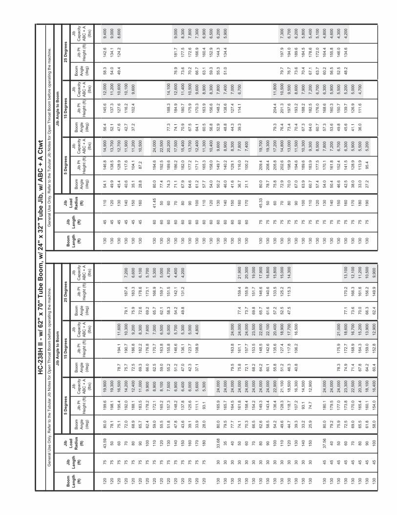
Boom
Ang
le(d
eg)
Jib
Pt
Hei
ght (
ft)
Boom
Ang
le(d
eg)
Jib
Pt
Hei
ght (
ft)Ji
b P
t H
eigh
t (ft)
Jib
Pt
Hei
ght (
ft)Ji
b P
t H
eigh
t (ft)
Boo
mLe
ngth
(ft)
Jib
Leng
th(ft
)
Jib
Load
Rad
ius
(ft)
Boom
Ang
le(d
eg)
Boom
Ang
le(d
eg)
Boom
Ang
le(d
eg)
HC
-238
H II
- w
/ 62"
x 7
0" T
ube
Boo
m, w
/ 24"
x 3
2" T
ube
Jib,
w/ A
BC
+ A
Ctw
t
25 D
egre
es15
Deg
rees
5 D
egre
es5
Deg
rees
15 D
egre
es25
Deg
rees
Jib
Ang
le to
Boo
m
Jib
Cap
acity
ABC
+ A
(lb
s)
Jib
Cap
acity
ABC
+ A
(lb
s)
Jib
Cap
acity
ABC
+ A
(lb
s)
Jib
Pt
Hei
ght (
ft)
Gen
eral
Use
Onl
y. R
efer
to th
e Tu
bula
r Jib
Not
es fo
r Ope
n Th
roat
Boo
m b
efor
e op
erat
ing
the
mac
hine
.
Boom
Ang
le(d
eg)
Boo
mLe
ngth
(ft)
Jib
Leng
th(ft
)
Jib
Load
Rad
ius
(ft)
Gen
eral
Use
Onl
y. R
efer
to th
e Tu
bula
r Jib
Not
es fo
r Ope
n Th
roat
Boo
m b
efor
e op
erat
ing
the
mac
hine
.
Jib
Ang
le to
Boo
m
Jib
Cap
acity
ABC
+ A
(lb
s)
Jib
Cap
acity
ABC
+ A
(lb
s)
Jib
Cap
acity
ABC
+ A
(lb
s)
120
7543
.59
80.0
199.
619
,900
130
4511
054
.114
6.8
14,9
0056
.414
5.6
12,0
0058
.314
2.6
9,40
0
120
7550
78.1
198.
119
,300
130
4512
049
.913
8.5
13,7
0052
.113
7.3
11,2
0054
.013
4.1
9,00
0
120
7560
75.1
195.
416
,500
78.7
194.
111
,600
130
4513
045
.412
8.9
12,7
0047
.612
7.6
10,6
0049
.412
4.2
8,60
0
120
7570
72.0
192.
014
,200
75.7
190.
710
,300
79.1
187.
47,
200
130
4514
040
.611
7.6
11,9
0042
.711
6.2
10,1
00
120
7580
68.9
188.
112
,400
72.5
186.
89,
200
75.9
183.
36,
600
130
4515
035
.110
4.1
11,2
0037
.210
2.4
9,60
0
120
7590
65.7
183.
511
,000
69.3
182.
28,
300
72.6
178.
66,
100
130
4516
028
.887
.210
,500
120
7510
062
.417
8.2
9,90
066
.017
6.8
7,60
069
.217
3.1
5,70
0
120
7511
059
.017
2.1
8,90
062
.517
0.7
7,00
065
.716
6.9
5,30
013
060
41.4
580
.019
4.6
24,0
00
120
7512
055
.516
5.2
8,10
059
.016
3.8
6,50
062
.115
9.7
5,00
013
060
5077
.419
2.5
22,5
00
120
7513
051
.815
7.3
7,50
055
.215
5.8
6,00
058
.315
1.5
4,70
013
060
6074
.318
9.6
20,2
0077
.318
8.3
14,1
00
120
7514
047
.814
8.2
6,90
051
.214
6.6
5,70
054
.214
2.1
4,40
013
060
7071
.118
6.2
17,5
0074
.118
4.9
12,6
0076
.918
1.7
9,00
0
120
7515
043
.613
7.8
6,40
047
.013
6.1
5,30
049
.813
1.2
4,20
013
060
8067
.918
2.0
15,4
0070
.918
0.7
11,4
0073
.617
7.5
8,30
0
120
7516
039
.112
5.6
6,00
042
.312
3.7
5,00
013
060
9064
.617
7.2
13,7
0067
.517
5.9
10,5
0070
.217
2.6
7,80
0
120
7517
033
.911
1.1
5,60
037
.110
8.9
4,80
013
060
100
61.2
171.
712
,400
64.1
170.
39,
600
66.7
166.
97,
300
120
7518
028
.093
.15,
300
130
6011
057
.716
5.3
11,3
0060
.516
3.9
8,90
063
.116
0.4
6,90
0
130
6012
054
.015
8.0
10,4
0056
.815
6.6
8,30
059
.315
2.9
6,50
0
130
3033
.68
80.0
165.
924
,000
130
6013
050
.214
9.7
9,60
052
.914
8.2
7,80
055
.314
4.3
6,20
0
130
3035
79.5
165.
724
,000
130
6014
046
.014
0.2
8,90
048
.813
8.6
7,40
051
.013
4.4
5,90
0
130
3040
77.7
164.
524
,000
79.5
163.
824
,000
130
6015
041
.612
9.1
8,30
044
.312
7.4
7,00
0
130
3050
74.1
161.
824
,000
75.8
161.
124
,000
77.4
159.
421
,900
130
6016
036
.711
6.0
7,80
039
.311
4.1
6,70
0
130
3060
70.3
158.
424
,000
72.1
157.
724
,000
73.7
155.
920
,300
130
6017
031
.110
0.2
7,40
0
130
3070
66.5
154.
224
,000
68.2
153.
523
,500
69.8
151.
719
,000
130
3080
62.6
149.
324
,000
64.2
148.
522
,600
65.7
146.
617
,900
130
7545
.33
80.0
209.
419
,700
130
3090
58.5
143.
424
,000
60.1
142.
622
,100
61.6
140.
616
,800
130
7550
78.7
208.
419
,300
130
3010
054
.213
6.4
22,9
0055
.813
5.6
20,4
0057
.213
3.5
15,8
0013
075
6075
.820
5.8
17,2
0079
.320
4.4
11,8
00
130
3011
049
.612
8.3
21,1
0051
.212
7.4
18,9
0052
.512
5.2
15,0
0013
075
7072
.920
2.6
14,8
0076
.420
1.3
10,5
0079
.719
7.9
7,30
0
130
3012
044
.711
8.7
18,5
0046
.311
7.8
17,7
0047
.511
5.3
14,3
0013
075
8070
.019
8.9
13,0
0073
.419
7.6
9,50
076
.719
4.0
6,70
0
130
3013
039
.310
7.2
16,3
0040
.810
6.2
16,5
0013
075
9067
.019
4.6
11,5
0070
.419
3.2
8,60
073
.618
9.6
6,20
0
130
3014
033
.293
.114
,500
130
7510
063
.918
9.6
10,3
0067
.318
8.2
7,90
070
.418
4.5
5,80
0
130
3015
025
.974
.712
,900
130
7511
060
.718
3.9
9,30
064
.018
2.5
7,20
067
.117
8.6
5,40
0
130
7512
057
.417
7.5
8,50
060
.717
6.0
6,70
063
.717
2.0
5,10
0
130
4537
.56
80.0
180.
124
,000
130
7513
054
.017
0.1
7,80
057
.316
8.6
6,30
060
.216
4.4
4,80
0
130
4540
79.2
179.
524
,000
130
7514
050
.416
1.8
7,20
053
.616
0.3
5,90
056
.515
5.8
4,60
0
130
4550
75.9
177.
024
,000
78.3
175.
921
,000
130
7515
046
.615
2.4
6,70
049
.815
0.7
5,50
052
.514
6.0
4,30
0
130
4560
72.5
173.
823
,300
74.9
172.
718
,600
77.1
170.
213
,100
130
7516
042
.514
1.5
6,30
045
.613
9.7
5,20
048
.213
4.6
4,20
0
130
4570
69.0
170.
022
,500
71.4
168.
916
,700
73.6
166.
312
,100
130
7517
038
.012
8.9
5,90
041
.112
6.9
5,00
0
130
4580
65.5
165.
420
,300
67.8
164.
315
,200
70.0
161.
611
,200
130
7518
033
.011
3.9
5,50
036
.011
1.6
4,70
0
130
4590
61.8
160.
118
,100
64.2
159.
013
,900
66.3
156.
210
,500
130
7519
027
.295
.45,
200
130
4510
058
.015
4.0
16,4
0060
.415
2.8
12,9
0062
.414
9.9
9,90
0
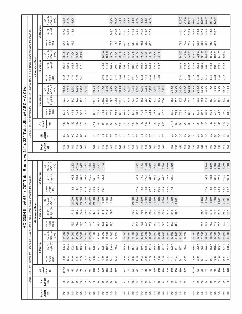
Boom
Ang
le(d
eg)
Jib
Pt
Hei
ght (
ft)
Boom
Ang
le(d
eg)
Jib
Pt
Hei
ght (
ft)Ji
b P
t H
eigh
t (ft)
Jib
Pt
Hei
ght (
ft)Ji
b P
t H
eigh
t (ft)
Boo
mLe
ngth
(ft)
Jib
Leng
th(ft
)
Jib
Load
Rad
ius
(ft)
Boom
Ang
le(d
eg)
Boom
Ang
le(d
eg)
Boom
Ang
le(d
eg)
HC
-238
H II
- w
/ 62"
x 7
0" T
ube
Boo
m, w
/ 24"
x 3
2" T
ube
Jib,
w/ A
BC
+ A
Ctw
t
25 D
egre
es15
Deg
rees
5 D
egre
es5
Deg
rees
15 D
egre
es25
Deg
rees
Jib
Ang
le to
Boo
m
Jib
Cap
acity
ABC
+ A
(lb
s)
Jib
Cap
acity
ABC
+ A
(lb
s)
Jib
Cap
acity
ABC
+ A
(lb
s)
Jib
Pt
Hei
ght (
ft)
Gen
eral
Use
Onl
y. R
efer
to th
e Tu
bula
r Jib
Not
es fo
r Ope
n Th
roat
Boo
m b
efor
e op
erat
ing
the
mac
hine
.
Boom
Ang
le(d
eg)
Boo
mLe
ngth
(ft)
Jib
Leng
th(ft
)
Jib
Load
Rad
ius
(ft)
Gen
eral
Use
Onl
y. R
efer
to th
e Tu
bula
r Jib
Not
es fo
r Ope
n Th
roat
Boo
m b
efor
e op
erat
ing
the
mac
hine
.
Jib
Ang
le to
Boo
m
Jib
Cap
acity
ABC
+ A
(lb
s)
Jib
Cap
acity
ABC
+ A
(lb
s)
Jib
Cap
acity
ABC
+ A
(lb
s)
140
3035
.42
80.0
175.
824
,000
140
6013
052
.516
2.9
10,0
0055
.216
1.4
8,10
057
.515
7.5
6,40
0
140
3040
78.4
174.
824
,000
140
6014
048
.815
4.1
9,30
051
.415
2.6
7,70
053
.614
8.5
6,10
0
140
3050
75.0
172.
324
,000
76.7
171.
524
,000
78.2
169.
822
,200
140
6015
044
.814
4.2
8,70
047
.414
2.5
7,30
049
.513
8.2
5,90
0
140
3060
71.5
169.
124
,000
73.2
168.
324
,000
74.7
166.
520
,700
140
6016
040
.513
2.7
8,20
043
.013
0.9
6,90
0
140
3070
67.9
165.
224
,000
69.6
164.
424
,000
71.0
162.
619
,400
140
6017
035
.711
9.1
7,70
038
.111
7.1
6,60
0
140
3080
64.3
160.
524
,000
65.9
159.
822
,500
67.3
157.
918
,300
140
6018
030
.310
2.8
7,30
0
140
3090
60.5
155.
124
,000
62.1
154.
322
,500
63.5
152.
317
,200
140
3010
056
.614
8.7
23,9
0058
.114
7.9
21,2
0059
.414
5.9
16,3
0014
075
47.0
680
.021
9.3
19,5
00
140
3011
052
.414
1.3
20,8
0053
.914
0.5
19,7
0055
.213
8.3
15,4
0014
075
5079
.221
8.6
19,3
00
140
3012
048
.013
2.7
18,2
0049
.513
1.8
18,4
0050
.712
9.5
14,7
0014
075
6076
.521
6.2
17,9
0079
.821
4.8
12,1
00
140
3013
043
.312
2.6
16,1
0044
.812
1.7
16,2
0014
075
7073
.721
3.2
15,4
0077
.021
1.8
10,8
00
140
3014
038
.111
0.6
14,2
0039
.510
9.5
14,3
0014
075
8070
.920
9.6
13,5
0074
.220
8.3
9,70
077
.320
4.7
6,80
0
140
3015
032
.295
.912
,600
140
7590
68.1
205.
512
,000
71.4
204.
18,
800
74.4
200.
56,
300
140
7510
065
.220
0.8
10,8
0068
.419
9.4
8,10
071
.419
5.7
5,90
0
140
4539
.380
.018
9.9
24,0
0014
075
110
62.2
195.
59,
700
65.4
194.
17,
500
68.3
190.
25,
500
140
4540
79.8
189.
824
,000
140
7512
059
.118
9.4
8,90
062
.318
8.0
6,90
065
.218
3.9
5,20
0
140
4550
76.6
187.
424
,000
78.9
186.
221
,500
140
7513
055
.918
2.6
8,20
059
.118
1.1
6,50
061
.917
6.9
4,90
0
140
4560
73.5
184.
424
,000
75.7
183.
219
,100
77.9
180.
713
,300
140
7514
052
.617
4.9
7,60
055
.717
3.4
6,10
058
.416
9.0
4,70
0
140
4570
70.2
180.
822
,500
72.5
179.
617
,200
74.6
177.
012
,300
140
7515
049
.116
6.3
7,00
052
.216
4.6
5,70
054
.816
0.0
4,40
0
140
4580
66.9
176.
521
,300
69.1
175.
415
,700
71.2
172.
711
,500
140
7516
045
.415
6.4
6,60
048
.415
4.7
5,40
051
.014
9.7
4,30
0
140
4590
63.5
171.
619
,000
65.7
170.
414
,400
67.7
167.
610
,800
140
7517
041
.414
5.2
6,20
044
.414
3.3
5,10
046
.813
7.9
4,10
0
140
4510
060
.016
5.8
17,2
0062
.216
4.6
13,3
0064
.116
1.8
10,2
0014
075
180
37.1
132.
25,
800
40.0
130.
04,
900
140
4511
056
.315
9.2
15,7
0058
.515
8.0
12,4
0060
.415
5.0
9,60
014
075
190
32.2
116.
75,
500
35.0
114.
24,
700
140
4512
052
.515
1.7
14,4
0054
.615
0.4
11,7
0056
.414
7.3
9,20
014
075
200
26.5
97.6
5,20
0
140
4513
048
.414
3.0
13,4
0050
.514
1.6
11,0
0052
.313
8.3
8,80
0
140
4514
044
.113
2.9
12,5
0046
.213
1.5
10,4
0047
.812
8.0
8,50
015
030
37.1
580
.018
5.6
24,0
00
140
4515
039
.412
1.1
11,7
0041
.411
9.6
9,90
015
030
4079
.118
5.0
24,0
00
140
4516
034
.110
7.1
11,0
0015
030
5075
.918
2.6
24,0
0077
.418
1.9
24,0
0078
.918
0.1
22,5
00
140
4517
028
.089
.610
,400
150
3060
72.6
179.
624
,000
74.1
178.
924
,000
75.6
177.
121
,000
150
3070
69.2
176.
024
,000
70.8
175.
224
,000
72.2
173.
419
,700
140
6043
.18
80.0
204.
424
,000
150
3080
65.8
171.
724
,000
67.3
170.
922
,900
68.7
169.
018
,600
140
6050
78.0
202.
922
,500
150
3090
62.3
166.
624
,000
63.8
165.
822
,500
65.1
163.
817
,700
140
6060
75.1
200.
121
,000
77.9
198.
814
,400
150
3010
058
.616
0.7
23,6
0060
.115
9.9
22,1
0061
.415
7.9
16,7
00
140
6070
72.1
196.
818
,200
74.9
195.
513
,000
77.6
192.
39,
100
150
3011
054
.815
3.9
20,6
0056
.315
3.1
20,5
0057
.515
1.0
15,8
00
140
6080
69.1
192.
916
,100
71.9
191.
611
,800
74.5
188.
38,
500
150
3012
050
.814
6.1
17,9
0052
.314
5.2
18,2
0053
.414
3.0
15,1
00
140
6090
66.0
188.
414
,300
68.7
187.
010
,800
71.3
183.
77,
900
150
3013
046
.613
7.0
15,8
0048
.013
6.1
16,0
0049
.113
3.7
14,5
00
140
6010
062
.818
3.2
13,0
0065
.518
1.8
9,90
068
.017
8.4
7,40
015
030
140
42.0
126.
413
,900
43.4
125.
414
,100
140
6011
059
.517
7.3
11,8
0062
.217
5.9
9,20
064
.717
2.3
7,00
015
030
150
37.0
113.
912
,400
38.3
112.
812
,500
140
6012
056
.117
0.5
10,8
0058
.816
9.1
8,60
061
.216
5.4
6,70
015
030
160
31.3
98.7
11,0
00

Boom
Ang
le(d
eg)
Jib
Pt
Hei
ght (
ft)
Boom
Ang
le(d
eg)
Jib
Pt
Hei
ght (
ft)Ji
b P
t H
eigh
t (ft)
Jib
Pt
Hei
ght (
ft)Ji
b P
t H
eigh
t (ft)
Boo
mLe
ngth
(ft)
Jib
Leng
th(ft
)
Jib
Load
Rad
ius
(ft)
Boom
Ang
le(d
eg)
Boom
Ang
le(d
eg)
Boom
Ang
le(d
eg)
HC
-238
H II
- w
/ 62"
x 7
0" T
ube
Boo
m, w
/ 24"
x 3
2" T
ube
Jib,
w/ A
BC
+ A
Ctw
t
25 D
egre
es15
Deg
rees
5 D
egre
es5
Deg
rees
15 D
egre
es25
Deg
rees
Jib
Ang
le to
Boo
m
Jib
Cap
acity
ABC
+ A
(lb
s)
Jib
Cap
acity
ABC
+ A
(lb
s)
Jib
Cap
acity
ABC
+ A
(lb
s)
Jib
Pt
Hei
ght (
ft)
Gen
eral
Use
Onl
y. R
efer
to th
e Tu
bula
r Jib
Not
es fo
r Ope
n Th
roat
Boo
m b
efor
e op
erat
ing
the
mac
hine
.
Boom
Ang
le(d
eg)
Boo
mLe
ngth
(ft)
Jib
Leng
th(ft
)
Jib
Load
Rad
ius
(ft)
Gen
eral
Use
Onl
y. R
efer
to th
e Tu
bula
r Jib
Not
es fo
r Ope
n Th
roat
Boo
m b
efor
e op
erat
ing
the
mac
hine
.
Jib
Ang
le to
Boo
m
Jib
Cap
acity
ABC
+ A
(lb
s)
Jib
Cap
acity
ABC
+ A
(lb
s)
Jib
Cap
acity
ABC
+ A
(lb
s)
150
7590
69.1
216.
412
,500
72.2
215.
09,
100
75.2
211.
36,
400
150
4541
.04
80.0
199.
824
,000
150
7510
066
.321
2.0
11,2
0069
.521
0.5
8,30
072
.320
6.7
6,00
0
150
4550
77.3
197.
724
,000
79.5
196.
522
,000
150
7511
063
.520
6.9
10,2
0066
.620
5.5
7,70
069
.420
1.5
5,60
0
150
4560
74.3
194.
924
,000
76.5
193.
719
,600
78.5
191.
113
,500
150
7512
060
.620
1.2
9,30
063
.719
9.7
7,20
066
.419
5.7
5,30
0
150
4570
71.3
191.
522
,500
73.4
190.
317
,700
75.4
187.
712
,500
150
7513
057
.619
4.8
8,50
060
.719
3.3
6,70
063
.418
9.1
5,00
0
150
4580
68.1
187.
522
,200
70.3
186.
316
,200
72.2
183.
611
,700
150
7514
054
.518
7.7
7,90
057
.518
6.1
6,30
060
.218
1.7
4,80
0
150
4590
64.9
182.
819
,900
67.0
181.
614
,900
69.0
178.
911
,000
150
7515
051
.317
9.6
7,30
054
.217
8.0
5,90
056
.817
3.4
4,60
0
150
4510
061
.617
7.4
18,0
0063
.717
6.3
13,8
0065
.617
3.4
10,4
0015
075
160
47.9
170.
66,
900
50.8
168.
95,
600
53.3
164.
04,
400
150
4511
058
.217
1.3
16,4
0060
.317
0.1
12,8
0062
.116
7.1
9,90
015
075
170
44.3
160.
46,
400
47.1
158.
55,
300
49.5
153.
44,
200
150
4512
054
.716
4.3
15,1
0056
.816
3.1
12,1
0058
.516
0.0
9,40
015
075
180
40.4
148.
76,
000
43.2
146.
75,
100
45.5
141.
14,
000
150
4513
051
.015
6.3
14,0
0053
.015
5.1
11,4
0054
.715
1.8
9,00
015
075
190
36.2
135.
35,
700
38.9
133.
04,
800
150
4514
047
.114
7.2
13,1
0049
.114
5.9
10,8
0050
.714
2.5
8,70
015
075
200
31.4
119.
45,
400
150
4515
042
.913
6.7
12,2
0044
.813
5.3
10,3
0015
075
210
25.9
99.7
5,20
0
150
4516
038
.312
4.5
11,3
0040
.212
2.9
9,80
0
150
4517
033
.211
0.0
10,1
0016
030
38.8
980
.019
5.5
24,0
00
150
4518
027
.291
.99,
000
160
3040
79.7
195.
224
,000
160
3050
76.6
193.
024
,000
78.1
192.
224
,000
79.5
190.
522
,500
150
6044
.92
80.0
214.
324
,000
160
3060
73.5
190.
124
,000
75.0
189.
424
,000
76.3
187.
621
,300
150
6050
78.6
213.
122
,400
160
3070
70.4
186.
724
,000
71.8
185.
924
,000
73.1
184.
120
,000
150
6060
75.8
210.
521
,800
78.5
209.
214
,700
160
3080
67.1
182.
624
,000
68.6
181.
923
,600
69.9
180.
019
,000
150
6070
73.0
207.
418
,900
75.7
206.
013
,300
78.2
202.
89,
300
160
3090
63.8
177.
924
,000
65.3
177.
122
,500
66.5
175.
218
,000
150
6080
70.1
203.
716
,700
72.8
202.
312
,100
75.3
199.
18,
600
160
3010
060
.417
2.4
23,3
0061
.917
1.6
22,5
0063
.116
9.6
17,1
00
150
6090
67.2
199.
415
,000
69.8
198.
111
,100
72.3
194.
78,
100
160
3011
056
.916
6.1
20,3
0058
.316
5.3
20,6
0059
.516
3.2
16,2
00
150
6010
064
.219
4.5
13,5
0066
.819
3.2
10,3
0069
.218
9.7
7,60
016
030
120
53.3
158.
917
,700
54.6
158.
017
,900
55.8
155.
915
,500
150
6011
061
.118
9.0
12,3
0063
.718
7.6
9,50
066
.118
4.0
7,20
016
030
130
49.4
150.
715
,500
50.7
149.
815
,700
51.8
147.
414
,900
150
6012
057
.918
2.7
11,3
0060
.518
1.2
8,90
062
.817
7.6
6,80
016
030
140
45.3
141.
213
,600
46.6
140.
213
,800
47.6
137.
714
,000
150
6013
054
.617
5.6
10,5
0057
.217
4.1
8,40
059
.417
0.3
6,50
016
030
150
40.8
130.
112
,100
42.1
129.
112
,200
150
6014
051
.216
7.5
9,70
053
.716
6.0
7,90
055
.816
2.0
6,20
016
030
160
36.0
117.
210
,700
37.2
116.
010
,800
150
6015
047
.515
8.4
9,10
050
.015
6.8
7,50
052
.115
2.6
6,00
016
030
170
30.4
101.
49,
500
150
6016
043
.614
8.1
8,60
046
.114
6.3
7,10
048
.014
1.8
5,80
0
150
6017
039
.413
6.1
8,10
041
.813
4.3
6,80
016
045
42.7
780
.020
9.6
24,0
00
150
6018
034
.812
2.2
7,70
037
.112
0.1
6,60
016
045
5078
.020
8.0
24,0
00
150
6019
029
.510
5.3
7,30
016
045
6075
.120
5.3
24,0
0077
.220
4.1
20,1
0079
.120
1.5
13,7
00
160
4570
72.2
202.
123
,000
74.3
200.
918
,200
76.2
198.
312
,700
150
7548
.880
.022
9.1
19,3
0016
045
8069
.219
8.3
22,5
0071
.319
7.1
16,6
0073
.219
4.4
11,9
00
150
7550
79.7
228.
919
,300
160
4590
66.2
193.
920
,700
68.2
192.
715
,300
70.1
189.
911
,200
150
7560
77.1
226.
518
,500
160
4510
063
.118
8.9
18,8
0065
.118
7.7
14,2
0066
.918
4.8
10,6
00
150
7570
74.5
223.
616
,000
77.6
222.
211
,000
160
4511
060
.018
3.1
17,2
0061
.918
1.9
13,2
0063
.717
9.0
10,1
00
150
7580
71.8
220.
314
,000
75.0
218.
910
,000
77.9
215.
36,
900
160
4512
056
.717
6.6
15,8
0058
.617
5.4
12,4
0060
.317
2.3
9,60
0

Boom
Ang
le(d
eg)
Jib
Pt
Hei
ght (
ft)
Boom
Ang
le(d
eg)
Jib
Pt
Hei
ght (
ft)Ji
b P
t H
eigh
t (ft)
Jib
Pt
Hei
ght (
ft)Ji
b P
t H
eigh
t (ft)
Boo
mLe
ngth
(ft)
Jib
Leng
th(ft
)
Jib
Load
Rad
ius
(ft)
Boom
Ang
le(d
eg)
Boom
Ang
le(d
eg)
Boom
Ang
le(d
eg)
HC
-238
H II
- w
/ 62"
x 7
0" T
ube
Boo
m, w
/ 24"
x 3
2" T
ube
Jib,
w/ A
BC
+ A
Ctw
t
25 D
egre
es15
Deg
rees
5 D
egre
es5
Deg
rees
15 D
egre
es25
Deg
rees
Jib
Ang
le to
Boo
m
Jib
Cap
acity
ABC
+ A
(lb
s)
Jib
Cap
acity
ABC
+ A
(lb
s)
Jib
Cap
acity
ABC
+ A
(lb
s)
Jib
Pt
Hei
ght (
ft)
Gen
eral
Use
Onl
y. R
efer
to th
e Tu
bula
r Jib
Not
es fo
r Ope
n Th
roat
Boo
m b
efor
e op
erat
ing
the
mac
hine
.
Boom
Ang
le(d
eg)
Boo
mLe
ngth
(ft)
Jib
Leng
th(ft
)
Jib
Load
Rad
ius
(ft)
Gen
eral
Use
Onl
y. R
efer
to th
e Tu
bula
r Jib
Not
es fo
r Ope
n Th
roat
Boo
m b
efor
e op
erat
ing
the
mac
hine
.
Jib
Ang
le to
Boo
m
Jib
Cap
acity
ABC
+ A
(lb
s)
Jib
Cap
acity
ABC
+ A
(lb
s)
Jib
Cap
acity
ABC
+ A
(lb
s)
160
4513
053
.216
9.2
14,6
0055
.216
8.0
11,7
0056
.816
4.8
9,20
016
075
190
39.5
152.
26,
000
42.1
150.
15,
000
160
4514
049
.716
0.9
13,6
0051
.515
9.6
11,1
0053
.115
6.2
8,90
016
075
200
35.4
138.
45,
700
37.9
136.
04,
800
160
4515
045
.915
1.4
12,4
0047
.715
0.0
10,6
0049
.214
6.5
8,60
016
075
210
30.7
122.
05,
400
160
4516
041
.814
0.5
11,0
0043
.613
9.0
10,1
0016
075
220
25.3
101.
95,
200
160
4517
037
.312
7.8
9,80
039
.112
6.2
9,70
0
160
4518
032
.311
2.8
8,80
017
030
40.6
380
.020
5.3
24,0
00
170
3050
77.3
203.
324
,000
78.7
202.
524
,000
160
6046
.66
80.0
224.
124
,000
170
3060
74.3
200.
624
,000
75.8
199.
824
,000
77.1
198.
021
,500
160
6050
79.1
223.
423
,100
170
3070
71.4
197.
324
,000
72.8
196.
624
,000
74.0
194.
720
,300
160
6060
76.5
220.
922
,400
79.1
219.
515
,000
170
3080
68.3
193.
524
,000
69.7
192.
724
,000
71.0
190.
819
,300
160
6070
73.8
217.
919
,600
76.4
216.
513
,600
78.8
213.
39,
400
170
3090
65.2
189.
024
,000
66.6
188.
322
,500
67.8
186.
318
,300
160
6080
71.0
214.
417
,400
73.6
213.
012
,400
76.0
209.
78,
800
170
3010
062
.118
3.9
23,0
0063
.418
3.1
22,5
0064
.618
1.1
17,5
00
160
6090
68.3
210.
415
,500
70.8
209.
011
,400
73.2
205.
68,
200
170
3011
058
.817
8.0
20,0
0060
.117
7.2
20,3
0061
.217
5.2
16,6
00
160
6010
065
.420
5.8
14,1
0068
.020
4.3
10,5
0070
.320
0.9
7,70
017
030
120
55.4
171.
317
,400
56.7
170.
517
,700
57.8
168.
415
,900
160
6011
062
.520
0.5
12,8
0065
.019
9.1
9,80
067
.319
5.5
7,30
017
030
130
51.8
163.
715
,200
53.1
162.
915
,400
54.2
160.
615
,200
160
6012
059
.519
4.6
11,8
0062
.019
3.1
9,20
064
.218
9.5
6,90
017
030
140
48.1
155.
113
,400
49.3
154.
213
,600
50.3
151.
813
,700
160
6013
056
.518
7.9
10,9
0058
.918
6.5
8,60
061
.018
2.7
6,60
017
030
150
44.1
145.
211
,800
45.3
144.
212
,000
46.3
141.
712
,100
160
6014
053
.218
0.5
10,2
0055
.717
8.9
8,10
057
.717
5.0
6,30
017
030
160
39.8
133.
710
,400
41.0
132.
610
,600
160
6015
049
.917
2.1
9,50
052
.317
0.5
7,70
054
.316
6.4
6,10
017
030
170
35.0
120.
39,
200
36.2
119.
19,
300
160
6016
046
.316
2.6
8,90
048
.716
0.9
7,40
050
.615
6.6
5,90
017
030
180
29.6
104.
08,
200
160
6017
042
.615
1.9
8,40
044
.915
0.1
7,00
046
.714
5.4
5,70
0
160
6018
038
.513
9.5
8,00
040
.713
7.6
6,80
017
045
44.5
180
.021
9.5
24,0
00
160
6019
034
.012
5.1
7,60
017
045
5078
.521
8.3
24,0
00
160
6020
028
.810
7.8
7,20
017
045
6075
.821
5.7
24,0
0077
.821
4.5
20,5
0079
.621
1.9
13,9
00
170
4570
73.0
212.
723
,800
75.0
211.
518
,600
76.8
208.
812
,900
160
7550
.54
80.0
239.
019
,100
170
4580
70.2
209.
122
,500
72.2
207.
917
,000
74.0
205.
112
,100
160
7560
77.7
236.
818
,500
170
4590
67.4
204.
921
,600
69.3
203.
715
,700
71.1
200.
911
,400
160
7570
75.2
234.
116
,600
78.2
232.
711
,200
170
4510
064
.520
0.2
19,6
0066
.419
8.9
14,6
0068
.119
6.1
10,8
00
160
7580
72.6
230.
914
,500
75.6
229.
510
,200
78.5
225.
87,
000
170
4511
061
.519
4.8
17,9
0063
.419
3.5
13,6
0065
.119
0.6
10,3
00
160
7590
70.0
227.
213
,000
73.0
225.
79,
300
75.8
222.
06,
500
170
4512
058
.418
8.7
16,5
0060
.318
7.4
12,8
0061
.918
4.4
9,80
0
160
7510
067
.422
3.0
11,7
0070
.422
1.5
8,60
073
.221
7.7
6,10
017
045
130
55.2
181.
815
,300
57.1
180.
512
,100
58.7
177.
49,
400
160
7511
064
.721
8.2
10,6
0067
.721
6.7
7,90
070
.421
2.8
5,70
017
045
140
51.9
174.
013
,700
53.7
172.
711
,500
55.3
169.
59,
100
160
7512
062
.021
2.8
9,70
064
.921
1.3
7,40
067
.620
7.2
5,40
017
045
150
48.4
165.
312
,100
50.2
163.
910
,900
51.7
160.
58,
700
160
7513
059
.220
6.8
8,90
062
.120
5.2
6,90
064
.720
1.1
5,10
017
045
160
44.7
155.
410
,700
46.5
154.
010
,400
47.9
150.
48,
500
160
7514
056
.320
0.1
8,20
059
.119
8.5
6,50
061
.719
4.1
4,90
017
045
170
40.7
144.
19,
500
42.4
142.
69,
700
160
7515
053
.219
2.6
7,70
056
.119
0.9
6,10
058
.618
6.4
4,70
017
045
180
36.4
131.
08,
500
38.1
129.
38,
600
160
7516
050
.118
4.2
7,20
052
.918
2.5
5,80
055
.317
7.7
4,50
017
045
190
31.5
115.
57,
500
160
7517
046
.817
4.8
6,70
049
.517
3.0
5,50
051
.916
8.0
4,30
0
160
7518
043
.316
4.2
6,30
046
.016
2.3
5,20
048
.215
6.9
4,10
017
060
48.3
980
.023
4.0
24,0
00

Boom
Ang
le(d
eg)
Jib
Pt
Hei
ght (
ft)
Boom
Ang
le(d
eg)
Jib
Pt
Hei
ght (
ft)Ji
b P
t H
eigh
t (ft)
Jib
Pt
Hei
ght (
ft)Ji
b P
t H
eigh
t (ft)
Boo
mLe
ngth
(ft)
Jib
Leng
th(ft
)
Jib
Load
Rad
ius
(ft)
Boom
Ang
le(d
eg)
Boom
Ang
le(d
eg)
Boom
Ang
le(d
eg)
HC
-238
H II
- w
/ 62"
x 7
0" T
ube
Boo
m, w
/ 24"
x 3
2" T
ube
Jib,
w/ A
BC
+ A
Ctw
t
25 D
egre
es15
Deg
rees
5 D
egre
es5
Deg
rees
15 D
egre
es25
Deg
rees
Jib
Ang
le to
Boo
m
Jib
Cap
acity
ABC
+ A
(lb
s)
Jib
Cap
acity
ABC
+ A
(lb
s)
Jib
Cap
acity
ABC
+ A
(lb
s)
Jib
Pt
Hei
ght (
ft)
Gen
eral
Use
Onl
y. R
efer
to th
e Tu
bula
r Jib
Not
es fo
r Ope
n Th
roat
Boo
m b
efor
e op
erat
ing
the
mac
hine
.
Boom
Ang
le(d
eg)
Boo
mLe
ngth
(ft)
Jib
Leng
th(ft
)
Jib
Load
Rad
ius
(ft)
Gen
eral
Use
Onl
y. R
efer
to th
e Tu
bula
r Jib
Not
es fo
r Ope
n Th
roat
Boo
m b
efor
e op
erat
ing
the
mac
hine
.
Jib
Ang
le to
Boo
m
Jib
Cap
acity
ABC
+ A
(lb
s)
Jib
Cap
acity
ABC
+ A
(lb
s)
Jib
Cap
acity
ABC
+ A
(lb
s)
170
6050
79.6
233.
623
,700
180
3060
75.1
211.
024
,000
76.4
210.
224
,000
77.7
208.
421
,800
170
6060
77.1
231.
322
,400
79.5
229.
815
,300
180
3070
72.3
207.
924
,000
73.6
207.
124
,000
74.8
205.
320
,600
170
6070
74.5
228.
420
,300
77.0
227.
013
,900
79.3
223.
79,
500
180
3080
69.4
204.
324
,000
70.7
203.
524
,000
71.9
201.
619
,500
170
6080
71.9
225.
118
,000
74.4
223.
712
,700
76.6
220.
38,
900
180
3090
66.5
200.
124
,000
67.8
199.
323
,100
69.0
197.
418
,600
170
6090
69.3
221.
216
,100
71.7
219.
811
,700
73.9
216.
48,
300
180
3010
063
.519
5.2
22,7
0064
.819
4.4
22,5
0065
.919
2.5
17,8
00
170
6010
066
.621
6.8
14,6
0069
.021
5.4
10,8
0071
.221
1.9
7,90
018
030
110
60.4
189.
719
,700
61.7
188.
920
,100
62.8
186.
917
,000
170
6011
063
.821
1.9
13,3
0066
.221
0.4
10,1
0068
.420
6.9
7,50
018
030
120
57.2
183.
517
,100
58.5
182.
617
,400
59.6
180.
516
,200
170
6012
061
.020
6.3
12,3
0063
.420
4.8
9,40
065
.520
1.2
7,10
018
030
130
53.9
176.
414
,900
55.2
175.
615
,200
56.2
173.
415
,400
170
6013
058
.120
0.0
11,4
0060
.419
8.6
8,90
062
.519
4.8
6,80
018
030
140
50.5
168.
413
,100
51.7
167.
513
,300
52.7
165.
213
,500
170
6014
055
.119
3.1
10,6
0057
.419
1.5
8,40
059
.418
7.6
6,50
018
030
150
46.8
159.
411
,500
48.0
158.
411
,700
49.0
156.
011
,800
170
6015
052
.018
5.2
9,90
054
.318
3.7
8,00
056
.217
9.6
6,20
018
030
160
43.0
149.
110
,100
44.1
148.
110
,300
170
6016
048
.717
6.5
9,30
051
.017
4.9
7,60
052
.917
0.6
6,00
018
030
170
38.8
137.
28,
900
39.9
136.
19,
100
170
6017
045
.316
6.7
8,70
047
.516
4.9
7,20
049
.316
0.4
5,80
018
030
180
34.1
123.
37,
900
170
6018
041
.615
5.6
8,30
043
.715
3.7
6,90
018
030
190
28.9
106.
56,
900
170
6019
037
.614
2.8
7,80
039
.714
0.8
6,70
0
170
6020
033
.212
8.0
6,90
018
045
46.2
580
.022
9.3
24,0
00
170
6021
028
.111
0.2
6,10
018
045
5079
.022
8.5
24,0
00
180
4560
76.4
226.
124
,000
78.3
224.
920
,900
170
7552
.27
80.0
248.
818
,900
180
4570
73.8
223.
224
,000
75.7
222.
019
,000
77.4
219.
313
,100
170
7560
78.2
247.
118
,400
180
4580
71.2
219.
822
,500
73.0
218.
517
,500
74.7
215.
812
,300
170
7570
75.8
244.
517
,100
78.7
243.
011
,500
180
4590
68.5
215.
822
,400
70.3
214.
616
,100
72.0
211.
811
,600
170
7580
73.3
241.
415
,100
76.2
240.
010
,400
79.0
236.
37,
100
180
4510
065
.721
1.3
20,3
0067
.521
0.1
15,0
0069
.220
7.2
11,0
00
170
7590
70.9
237.
913
,400
73.8
236.
49,
500
76.5
232.
76,
600
180
4511
062
.920
6.2
18,6
0064
.720
5.0
14,0
0066
.320
2.0
10,5
00
170
7510
068
.423
3.9
12,1
0071
.223
2.4
8,80
073
.922
8.5
6,20
018
045
120
60.0
200.
517
,100
61.8
199.
213
,200
63.3
196.
210
,000
170
7511
065
.822
9.3
11,0
0068
.722
7.8
8,10
071
.322
3.9
5,80
018
045
130
57.0
194.
015
,200
58.8
192.
712
,400
60.3
189.
69,
600
170
7512
063
.222
4.2
10,1
0066
.122
2.7
7,60
068
.621
8.6
5,50
018
045
140
53.9
186.
813
,400
55.6
185.
511
,800
57.1
182.
39,
200
170
7513
060
.621
8.5
9,30
063
.421
7.0
7,10
065
.921
2.8
5,20
018
045
150
50.6
178.
711
,800
52.4
177.
411
,200
53.8
174.
08,
900
170
7514
057
.821
2.2
8,60
060
.621
0.6
6,70
063
.120
6.3
5,00
018
045
160
47.2
169.
610
,400
48.9
168.
210
,700
50.3
164.
78,
600
170
7515
055
.020
5.2
8,00
057
.720
3.5
6,30
060
.219
9.0
4,70
018
045
170
43.6
159.
49,
200
45.3
157.
99,
400
170
7516
052
.019
7.3
7,40
054
.819
5.6
5,90
057
.119
1.0
4,50
018
045
180
39.8
147.
78,
200
41.4
146.
18,
400
170
7517
049
.018
8.6
7,00
051
.618
6.8
5,60
053
.918
1.9
4,40
018
045
190
35.5
134.
27,
200
37.1
132.
47,
400
170
7518
045
.717
8.9
6,60
048
.417
7.0
5,40
050
.617
1.8
4,20
018
045
200
30.8
118.
26,
400
170
7519
042
.316
8.0
6,20
044
.916
6.0
5,10
047
.016
0.4
4,10
0
170
7520
038
.615
5.6
5,90
041
.115
3.4
4,90
018
060
50.1
380
.024
3.8
24,0
00
170
7521
034
.614
1.3
5,60
037
.013
8.9
4,70
018
060
6077
.624
1.6
22,3
00
170
7522
030
.012
4.6
5,30
018
060
7075
.223
8.9
21,0
0077
.523
7.4
14,1
0079
.823
4.1
9,60
0
180
6080
72.7
235.
718
,600
75.0
234.
212
,900
77.2
230.
99,
000
180
3042
.36
80.0
215.
224
,000
180
6090
70.2
232.
016
,700
72.5
230.
611
,900
74.7
227.
28,
500
180
3050
77.9
213.
624
,000
79.2
212.
824
,000
180
6010
067
.622
7.8
15,1
0069
.922
6.4
11,1
0072
.122
2.9
8,00
0

Boom
Ang
le(d
eg)
Jib
Pt
Hei
ght (
ft)
Boom
Ang
le(d
eg)
Jib
Pt
Hei
ght (
ft)Ji
b P
t H
eigh
t (ft)
Jib
Pt
Hei
ght (
ft)Ji
b P
t H
eigh
t (ft)
Boo
mLe
ngth
(ft)
Jib
Leng
th(ft
)
Jib
Load
Rad
ius
(ft)
Boom
Ang
le(d
eg)
Boom
Ang
le(d
eg)
Boom
Ang
le(d
eg)
HC
-238
H II
- w
/ 62"
x 7
0" T
ube
Boo
m, w
/ 24"
x 3
2" T
ube
Jib,
w/ A
BC
+ A
Ctw
t
25 D
egre
es15
Deg
rees
5 D
egre
es5
Deg
rees
15 D
egre
es25
Deg
rees
Jib
Ang
le to
Boo
m
Jib
Cap
acity
ABC
+ A
(lb
s)
Jib
Cap
acity
ABC
+ A
(lb
s)
Jib
Cap
acity
ABC
+ A
(lb
s)
Jib
Pt
Hei
ght (
ft)
Gen
eral
Use
Onl
y. R
efer
to th
e Tu
bula
r Jib
Not
es fo
r Ope
n Th
roat
Boo
m b
efor
e op
erat
ing
the
mac
hine
.
Boom
Ang
le(d
eg)
Boo
mLe
ngth
(ft)
Jib
Leng
th(ft
)
Jib
Load
Rad
ius
(ft)
Gen
eral
Use
Onl
y. R
efer
to th
e Tu
bula
r Jib
Not
es fo
r Ope
n Th
roat
Boo
m b
efor
e op
erat
ing
the
mac
hine
.
Jib
Ang
le to
Boo
m
Jib
Cap
acity
ABC
+ A
(lb
s)
Jib
Cap
acity
ABC
+ A
(lb
s)
Jib
Cap
acity
ABC
+ A
(lb
s)
180
6011
065
.022
3.1
13,8
0067
.322
1.7
10,3
0069
.421
8.1
7,60
019
030
100
64.8
206.
422
,400
66.0
205.
622
,500
67.1
203.
718
,100
180
6012
062
.321
7.8
12,7
0064
.621
6.3
9,70
066
.721
2.7
7,20
019
030
110
61.9
201.
219
,400
63.1
200.
419
,800
64.2
198.
417
,300
180
6013
059
.621
1.9
11,8
0061
.821
0.4
9,10
063
.920
6.7
6,90
019
030
120
58.9
195.
416
,800
60.1
194.
517
,100
61.1
192.
416
,600
180
6014
056
.820
5.3
11,0
0059
.020
3.8
8,60
061
.019
9.9
6,60
019
030
130
55.8
188.
814
,600
57.0
187.
914
,900
58.0
185.
815
,100
180
6015
053
.819
8.0
10,3
0056
.019
6.5
8,20
058
.019
2.4
6,30
019
030
140
52.6
181.
412
,800
53.8
180.
513
,000
54.7
178.
213
,200
180
6016
050
.818
9.9
9,60
053
.018
8.3
7,80
054
.818
4.1
6,10
019
030
150
49.2
173.
011
,200
50.4
172.
111
,400
51.3
169.
711
,600
180
6017
047
.618
0.8
9,10
049
.817
9.1
7,40
051
.517
4.7
5,90
019
030
160
45.7
163.
69,
800
46.8
162.
610
,000
47.7
160.
110
,100
180
6018
044
.217
0.6
8,40
046
.316
8.8
7,10
048
.016
4.2
5,70
019
030
170
41.9
152.
98,
600
43.0
151.
88,
800
180
6019
040
.615
9.2
7,50
042
.715
7.2
6,90
019
030
180
37.8
140.
67,
600
38.9
139.
57,
700
180
6020
036
.814
6.0
6,60
038
.814
3.9
6,60
019
030
190
33.3
126.
36,
600
180
6021
032
.413
0.8
5,80
019
030
200
28.2
109.
05,
800
180
6022
027
.511
2.5
5,20
0
190
4547
.98
80.0
239.
124
,000
180
7554
.01
80.0
258.
718
,700
190
4550
79.5
238.
724
,000
180
7560
78.6
257.
418
,300
190
4560
77.0
236.
424
,000
78.8
235.
221
,300
180
7570
76.3
254.
917
,700
79.1
253.
411
,700
190
4570
74.5
233.
624
,000
76.3
232.
419
,400
78.0
229.
713
,300
180
7580
74.0
251.
915
,600
76.8
250.
510
,600
79.4
246.
77,
200
190
4580
72.0
230.
422
,700
73.8
229.
217
,900
75.4
226.
412
,500
180
7590
71.7
248.
613
,900
74.4
247.
19,
700
77.0
243.
36,
700
190
4590
69.4
226.
622
,400
71.2
225.
416
,500
72.8
222.
611
,800
180
7510
069
.324
4.7
12,5
0072
.024
3.2
9,00
074
.623
9.3
6,30
019
045
100
66.8
222.
321
,100
68.5
221.
115
,400
70.1
218.
311
,200
180
7511
066
.824
0.4
11,4
0069
.623
8.9
8,30
072
.123
4.9
5,90
019
045
110
64.1
217.
519
,300
65.9
216.
314
,400
67.4
213.
310
,600
180
7512
064
.423
5.5
10,4
0067
.123
4.0
7,80
069
.622
9.9
5,60
019
045
120
61.4
212.
117
,200
63.1
210.
813
,500
64.6
207.
810
,200
180
7513
061
.823
0.1
9,60
064
.522
8.6
7,30
067
.022
4.4
5,30
019
045
130
58.5
206.
015
,000
60.3
204.
712
,800
61.8
201.
79,
800
180
7514
059
.222
4.1
8,90
061
.922
2.5
6,80
064
.321
8.2
5,10
019
045
140
55.6
199.
213
,100
57.3
197.
912
,100
58.8
194.
89,
400
180
7515
056
.621
7.5
8,30
059
.221
5.8
6,40
061
.621
1.4
4,80
019
045
150
52.6
191.
711
,500
54.3
190.
311
,500
55.7
187.
19,
100
180
7516
053
.821
0.1
7,70
056
.420
8.4
6,10
058
.720
3.8
4,60
019
045
160
49.5
183.
210
,100
51.1
181.
910
,400
52.5
178.
48,
800
180
7517
050
.920
2.0
7,30
053
.520
0.2
5,80
055
.719
5.4
4,50
019
045
170
46.2
173.
88,
900
47.8
172.
49,
200
49.1
168.
88,
500
180
7518
047
.919
3.0
6,80
050
.519
1.1
5,50
052
.618
6.1
4,30
019
045
180
42.6
163.
27,
900
44.2
161.
78,
100
180
7519
044
.818
2.9
6,40
047
.318
0.9
5,30
049
.417
5.6
4,10
019
045
190
38.9
151.
16,
900
40.4
149.
57,
100
180
7520
041
.417
1.6
6,10
043
.916
9.5
5,10
045
.816
3.8
4,00
019
045
200
34.7
137.
26,
100
180
7521
037
.815
8.9
5,80
040
.215
6.6
4,90
019
045
210
30.1
120.
85,
300
180
7522
033
.914
4.3
5,30
036
.214
1.7
4,70
0
180
7523
029
.412
7.1
4,70
019
060
51.8
780
.025
3.7
23,6
00
190
6060
78.1
251.
922
,000
190
3044
.180
.022
5.0
24,0
0019
060
7075
.824
9.3
21,4
0078
.024
7.8
14,4
00
190
3050
78.4
223.
824
,000
79.7
223.
024
,000
190
6080
73.4
246.
219
,200
75.7
244.
813
,200
77.8
241.
49,
100
190
3060
75.8
221.
424
,000
77.1
220.
624
,000
78.3
218.
822
,000
190
6090
71.0
242.
717
,300
73.2
241.
312
,200
75.3
237.
88,
600
190
3070
73.1
218.
424
,000
74.4
217.
724
,000
75.5
215.
820
,800
190
6010
068
.523
8.7
15,7
0070
.823
7.3
11,3
0072
.823
3.8
8,10
0
190
3080
70.4
215.
024
,000
71.6
214.
224
,000
72.8
212.
319
,800
190
6011
066
.123
4.2
14,3
0068
.323
2.8
10,6
0070
.322
9.2
7,70
0
190
3090
67.6
211.
024
,000
68.9
210.
223
,700
70.0
208.
318
,900
190
6012
063
.522
9.2
13,2
0065
.722
7.7
9,90
067
.722
4.1
7,30
0
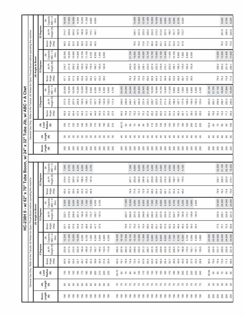
Boom
Ang
le(d
eg)
Jib
Pt
Hei
ght (
ft)
Boom
Ang
le(d
eg)
Jib
Pt
Hei
ght (
ft)Ji
b P
t H
eigh
t (ft)
Jib
Pt
Hei
ght (
ft)Ji
b P
t H
eigh
t (ft)
Boo
mLe
ngth
(ft)
Jib
Leng
th(ft
)
Jib
Load
Rad
ius
(ft)
Boom
Ang
le(d
eg)
Boom
Ang
le(d
eg)
Boom
Ang
le(d
eg)
HC
-238
H II
- w
/ 62"
x 7
0" T
ube
Boo
m, w
/ 24"
x 3
2" T
ube
Jib,
w/ A
BC
+ A
Ctw
t
25 D
egre
es15
Deg
rees
5 D
egre
es5
Deg
rees
15 D
egre
es25
Deg
rees
Jib
Ang
le to
Boo
m
Jib
Cap
acity
ABC
+ A
(lb
s)
Jib
Cap
acity
ABC
+ A
(lb
s)
Jib
Cap
acity
ABC
+ A
(lb
s)
Jib
Pt
Hei
ght (
ft)
Gen
eral
Use
Onl
y. R
efer
to th
e Tu
bula
r Jib
Not
es fo
r Ope
n Th
roat
Boo
m b
efor
e op
erat
ing
the
mac
hine
.
Boom
Ang
le(d
eg)
Boo
mLe
ngth
(ft)
Jib
Leng
th(ft
)
Jib
Load
Rad
ius
(ft)
Gen
eral
Use
Onl
y. R
efer
to th
e Tu
bula
r Jib
Not
es fo
r Ope
n Th
roat
Boo
m b
efor
e op
erat
ing
the
mac
hine
.
Jib
Ang
le to
Boo
m
Jib
Cap
acity
ABC
+ A
(lb
s)
Jib
Cap
acity
ABC
+ A
(lb
s)
Jib
Cap
acity
ABC
+ A
(lb
s)
190
6013
060
.922
3.6
12,2
0063
.122
2.1
9,30
065
.021
8.4
7,00
020
030
100
65.9
217.
522
,400
67.1
216.
722
,500
68.2
214.
718
,400
190
6014
058
.321
7.4
11,4
0060
.421
5.9
8,80
062
.321
2.0
6,70
020
030
110
63.2
212.
619
,200
64.4
211.
819
,500
65.4
209.
817
,600
190
6015
055
.521
0.5
10,6
0057
.620
8.9
8,40
059
.520
5.0
6,50
020
030
120
60.4
207.
016
,500
61.5
206.
216
,900
62.5
204.
216
,900
190
6016
052
.720
2.9
10,0
0054
.820
1.3
8,00
056
.619
7.2
6,20
020
030
130
57.5
200.
814
,300
58.6
200.
014
,600
59.6
197.
914
,900
190
6017
049
.719
4.4
9,20
051
.819
2.8
7,60
053
.518
8.5
6,00
020
030
140
54.5
193.
912
,500
55.6
193.
012
,700
56.5
190.
813
,000
190
6018
046
.618
5.0
8,10
048
.618
3.3
7,30
050
.317
8.8
5,80
020
030
150
51.3
186.
110
,900
52.5
185.
211
,100
53.4
182.
911
,300
190
6019
043
.317
4.5
7,20
045
.317
2.7
7,00
046
.916
7.9
5,70
020
030
160
48.1
177.
59,
500
49.2
176.
59,
700
50.0
174.
19,
900
190
6020
039
.816
2.7
6,30
041
.716
0.7
6,50
020
030
170
44.6
167.
78,
300
45.7
166.
78,
500
46.5
164.
18,
600
190
6021
036
.014
9.2
5,60
037
.914
7.0
5,70
020
030
180
40.9
156.
67,
300
42.0
155.
57,
400
190
6022
031
.813
3.5
4,90
020
030
190
37.0
143.
96,
300
38.0
142.
86,
500
190
6023
026
.911
4.8
4,20
020
030
200
32.6
129.
25,
500
200
3021
027
.511
1.4
4,70
0
190
7555
.75
80.0
268.
518
,400
190
7560
79.1
267.
618
,100
200
4549
.72
80.0
249.
024
,000
190
7570
76.9
265.
217
,600
79.6
263.
711
,900
200
4550
79.9
248.
924
,000
190
7580
74.6
262.
416
,100
77.3
260.
910
,800
79.9
257.
17,
300
200
4560
77.6
246.
724
,000
79.3
245.
521
,700
190
7590
72.4
259.
214
,300
75.0
257.
69,
900
77.6
253.
86,
800
200
4570
75.2
244.
124
,000
76.9
242.
819
,800
78.5
240.
113
,400
190
7510
070
.125
5.5
12,9
0072
.725
4.0
9,20
075
.225
0.0
6,40
020
045
8072
.724
0.9
23,4
0074
.523
9.7
18,2
0076
.023
7.0
12,6
00
190
7511
067
.825
1.3
11,8
0070
.424
9.8
8,50
072
.824
5.8
6,00
020
045
9070
.323
7.4
22,4
0072
.023
6.1
16,9
0073
.623
3.3
12,0
00
190
7512
065
.424
6.7
10,8
0068
.024
5.1
8,00
070
.424
1.1
5,70
020
045
100
67.8
233.
321
,900
69.5
232.
015
,700
71.0
229.
211
,400
190
7513
063
.024
1.5
9,90
065
.624
0.0
7,50
068
.023
5.8
5,40
020
045
110
65.2
228.
719
,500
66.9
227.
414
,700
68.4
224.
510
,800
190
7514
060
.523
5.8
9,20
063
.123
4.2
7,00
065
.422
9.9
5,20
020
045
120
62.6
223.
516
,900
64.3
222.
313
,900
65.8
219.
310
,400
190
7515
058
.022
9.6
8,60
060
.522
7.9
6,60
062
.822
3.5
4,90
020
045
130
60.0
217.
814
,700
61.6
216.
513
,100
63.1
213.
59,
900
190
7516
055
.422
2.6
8,00
057
.922
0.9
6,30
060
.121
6.3
4,70
020
045
140
57.2
211.
412
,800
58.9
210.
112
,400
60.3
207.
09,
600
190
7517
052
.721
5.0
7,50
055
.221
3.2
6,00
057
.420
8.5
4,50
020
045
150
54.4
204.
311
,200
56.0
203.
011
,600
57.4
199.
79,
200
190
7518
049
.920
6.5
7,10
052
.420
4.7
5,70
054
.519
9.7
4,40
020
045
160
51.4
196.
49,
800
53.0
195.
110
,100
54.4
191.
78,
900
190
7519
046
.919
7.2
6,70
049
.419
5.3
5,40
051
.419
0.1
4,20
020
045
170
48.4
187.
78,
600
49.9
186.
38,
900
51.2
182.
88,
700
190
7520
043
.918
6.8
6,30
046
.318
4.8
5,20
048
.217
9.3
4,10
020
045
180
45.1
177.
97,
600
46.7
176.
47,
800
47.9
172.
78,
000
190
7521
040
.617
5.2
5,70
042
.917
3.1
5,00
020
045
190
41.7
166.
96,
600
43.2
165.
46,
800
190
7522
037
.016
2.1
5,00
039
.315
9.8
4,80
020
045
200
38.0
154.
55,
800
39.5
152.
86,
000
190
7523
033
.214
7.1
4,40
035
.414
4.5
4,60
020
045
210
34.0
140.
25,
000
190
7524
028
.812
9.5
3,80
020
045
220
29.5
123.
44,
300
200
3045
.84
80.0
234.
924
,000
200
6053
.680
.026
3.5
22,1
00
200
3050
79.0
234.
024
,000
200
6060
78.6
262.
121
,700
200
3060
76.4
231.
724
,000
77.6
230.
924
,000
78.8
229.
122
,200
200
6070
76.3
259.
621
,100
78.5
258.
214
,600
200
3070
73.9
228.
924
,000
75.1
228.
124
,000
76.2
226.
321
,100
200
6080
74.0
256.
719
,800
76.2
255.
213
,500
78.3
251.
89,
200
200
3080
71.3
225.
624
,000
72.5
224.
824
,000
73.6
223.
020
,100
200
6090
71.7
253.
317
,800
73.9
251.
912
,400
75.9
248.
48,
700
200
3090
68.6
221.
824
,000
69.8
221.
024
,000
70.9
219.
119
,200
200
6010
069
.424
9.5
16,2
0071
.624
8.1
11,6
0073
.524
4.6
8,20
0

Boom
Ang
le(d
eg)
Jib
Pt
Hei
ght (
ft)
Boom
Ang
le(d
eg)
Jib
Pt
Hei
ght (
ft)Ji
b P
t H
eigh
t (ft)
Jib
Pt
Hei
ght (
ft)Ji
b P
t H
eigh
t (ft)
Boo
mLe
ngth
(ft)
Jib
Leng
th(ft
)
Jib
Load
Rad
ius
(ft)
Boom
Ang
le(d
eg)
Boom
Ang
le(d
eg)
Boom
Ang
le(d
eg)
HC
-238
H II
- w
/ 62"
x 7
0" T
ube
Boo
m, w
/ 24"
x 3
2" T
ube
Jib,
w/ A
BC
+ A
Ctw
t
25 D
egre
es15
Deg
rees
5 D
egre
es5
Deg
rees
15 D
egre
es25
Deg
rees
Jib
Ang
le to
Boo
m
Jib
Cap
acity
ABC
+ A
(lb
s)
Jib
Cap
acity
ABC
+ A
(lb
s)
Jib
Cap
acity
ABC
+ A
(lb
s)
Jib
Pt
Hei
ght (
ft)
Gen
eral
Use
Onl
y. R
efer
to th
e Tu
bula
r Jib
Not
es fo
r Ope
n Th
roat
Boo
m b
efor
e op
erat
ing
the
mac
hine
.
Boom
Ang
le(d
eg)
Boo
mLe
ngth
(ft)
Jib
Leng
th(ft
)
Jib
Load
Rad
ius
(ft)
Gen
eral
Use
Onl
y. R
efer
to th
e Tu
bula
r Jib
Not
es fo
r Ope
n Th
roat
Boo
m b
efor
e op
erat
ing
the
mac
hine
.
Jib
Ang
le to
Boo
m
Jib
Cap
acity
ABC
+ A
(lb
s)
Jib
Cap
acity
ABC
+ A
(lb
s)
Jib
Cap
acity
ABC
+ A
(lb
s)
200
6011
067
.024
5.2
14,8
0069
.224
3.8
10,8
0071
.124
0.2
7,80
021
030
7074
.523
9.3
24,0
0075
.723
8.5
24,0
0076
.823
6.7
21,3
00
200
6012
064
.624
0.5
13,6
0066
.723
9.0
10,2
0068
.623
5.3
7,40
021
030
8072
.123
6.2
24,0
0073
.223
5.4
24,0
0074
.323
3.5
20,3
00
200
6013
062
.123
5.1
12,6
0064
.223
3.6
9,60
066
.122
9.9
7,10
021
030
9069
.623
2.6
24,0
0070
.723
1.8
24,0
0071
.722
9.9
19,4
00
200
6014
059
.622
9.2
11,8
0061
.722
7.7
9,10
063
.522
3.9
6,80
021
030
100
67.0
228.
522
,100
68.1
227.
622
,300
69.2
225.
718
,600
200
6015
057
.022
2.7
11,0
0059
.122
1.2
8,60
060
.921
7.2
6,60
021
030
110
64.4
223.
818
,900
65.5
223.
019
,300
66.5
221.
017
,900
200
6016
054
.321
5.5
10,1
0056
.421
3.9
8,20
058
.120
9.9
6,30
021
030
120
61.7
218.
516
,200
62.8
217.
716
,600
63.8
215.
716
,900
200
6017
051
.520
7.6
8,90
053
.620
6.0
7,80
055
.320
1.7
6,10
021
030
130
59.0
212.
714
,100
60.1
211.
814
,400
61.0
209.
714
,600
200
6018
048
.619
8.9
7,80
050
.619
7.1
7,50
052
.319
2.7
5,90
021
030
140
56.1
206.
212
,200
57.2
205.
312
,500
58.2
203.
112
,700
200
6019
045
.618
9.1
6,90
047
.618
7.3
7,10
049
.118
2.7
5,80
021
030
150
53.2
198.
910
,600
54.3
198.
010
,800
55.2
195.
811
,000
200
6020
042
.417
8.3
6,00
044
.317
6.4
6,30
021
030
160
50.2
190.
89,
200
51.2
189.
99,
400
52.1
187.
59,
600
200
6021
039
.016
6.1
5,20
040
.816
4.1
5,50
021
030
170
47.0
181.
88,
000
48.0
180.
88,
200
48.9
178.
48,
400
200
6022
035
.215
2.3
4,60
037
.015
0.0
4,70
021
030
180
43.6
171.
77,
000
44.7
170.
67,
100
200
6023
031
.113
6.2
3,90
021
030
190
40.0
160.
26,
000
41.0
159.
16,
200
210
3020
036
.214
7.2
5,20
037
.114
6.0
5,30
0
200
7557
.48
80.0
278.
418
,100
210
3021
031
.913
2.0
4,40
0
200
7560
79.5
277.
817
,900
210
3022
026
.911
3.8
3,80
0
200
7570
77.3
275.
517
,400
200
7580
75.2
272.
816
,500
77.8
271.
311
,000
210
4551
.46
80.0
258.
824
,000
200
7590
73.0
269.
714
,800
75.6
268.
210
,100
78.0
264.
36,
900
210
4560
78.1
257.
024
,000
79.7
255.
822
,100
200
7510
070
.826
6.2
13,4
0073
.426
4.6
9,40
075
.826
0.7
6,50
021
045
7075
.825
4.4
24,0
0077
.425
3.2
20,2
0079
.025
0.5
13,6
00
200
7511
068
.626
2.2
12,2
0071
.226
0.7
8,70
073
.525
6.6
6,10
021
045
8073
.425
1.5
24,0
0075
.125
0.2
18,6
0076
.624
7.5
12,8
00
200
7512
066
.425
7.8
11,1
0068
.925
6.2
8,10
071
.225
2.1
5,80
021
045
9071
.124
8.0
22,4
0072
.724
6.8
17,3
0074
.224
4.0
12,1
00
200
7513
064
.125
2.9
10,3
0066
.625
1.3
7,60
068
.924
7.1
5,50
021
045
100
68.7
244.
122
,400
70.3
242.
916
,100
71.8
240.
011
,500
200
7514
061
.724
7.4
9,50
064
.224
5.8
7,20
066
.424
1.5
5,20
021
045
110
66.3
239.
719
,200
67.9
238.
515
,100
69.3
235.
611
,000
200
7515
059
.324
1.4
8,90
061
.823
9.8
6,80
064
.023
5.4
5,00
021
045
120
63.8
234.
816
,600
65.4
233.
614
,200
66.8
230.
610
,500
200
7516
056
.823
4.9
8,30
059
.323
3.2
6,40
061
.422
8.6
4,80
021
045
130
61.3
229.
414
,400
62.9
228.
113
,400
64.3
225.
110
,100
200
7517
054
.322
7.6
7,80
056
.722
5.9
6,10
058
.822
1.2
4,60
021
045
140
58.7
223.
312
,500
60.2
222.
012
,700
61.6
218.
99,
700
200
7518
051
.621
9.7
7,30
054
.021
7.9
5,80
056
.121
3.0
4,40
021
045
150
56.0
216.
610
,900
57.5
215.
311
,300
58.9
212.
19,
400
200
7519
048
.921
1.0
6,90
051
.320
9.1
5,60
053
.320
4.0
4,30
021
045
160
53.2
209.
29,
500
54.8
207.
99,
900
56.1
204.
69,
100
200
7520
046
.020
1.3
6,20
048
.419
9.4
5,30
050
.319
4.0
4,20
021
045
170
50.4
201.
18,
300
51.9
199.
78,
600
53.1
196.
28,
800
200
7521
043
.019
0.7
5,40
045
.318
8.6
5,10
047
.118
2.9
4,00
021
045
180
47.4
192.
07,
300
48.8
190.
57,
500
50.1
187.
07,
700
200
7522
039
.817
8.7
4,70
042
.017
6.5
4,90
021
045
190
44.2
181.
96,
300
45.7
180.
46,
500
200
7523
036
.316
5.3
4,10
038
.516
2.8
4,30
021
045
200
40.8
170.
65,
500
42.3
169.
05,
700
200
7524
032
.514
9.9
3,50
021
045
210
37.2
157.
84,
700
38.6
156.
14,
900
200
7525
028
.313
1.9
3,00
021
045
220
33.3
143.
14,
000
210
4523
028
.912
5.9
3,40
0
210
3047
.57
80.0
244.
724
,000
210
3050
79.4
244.
224
,000
210
6055
.34
80.0
273.
421
,600
210
3060
77.0
242.
024
,000
78.2
241.
224
,000
79.3
239.
422
,400
210
6060
79.0
272.
421
,300

Boom
Ang
le(d
eg)
Jib
Pt
Hei
ght (
ft)
Boom
Ang
le(d
eg)
Jib
Pt
Hei
ght (
ft)Ji
b P
t H
eigh
t (ft)
Jib
Pt
Hei
ght (
ft)Ji
b P
t H
eigh
t (ft)
Boo
mLe
ngth
(ft)
Jib
Leng
th(ft
)
Jib
Load
Rad
ius
(ft)
Boom
Ang
le(d
eg)
Boom
Ang
le(d
eg)
Boom
Ang
le(d
eg)
HC
-238
H II
- w
/ 62"
x 7
0" T
ube
Boo
m, w
/ 24"
x 3
2" T
ube
Jib,
w/ A
BC
+ A
Ctw
t
25 D
egre
es15
Deg
rees
5 D
egre
es5
Deg
rees
15 D
egre
es25
Deg
rees
Jib
Ang
le to
Boo
m
Jib
Cap
acity
ABC
+ A
(lb
s)
Jib
Cap
acity
ABC
+ A
(lb
s)
Jib
Cap
acity
ABC
+ A
(lb
s)
Jib
Pt
Hei
ght (
ft)
Gen
eral
Use
Onl
y. R
efer
to th
e Tu
bula
r Jib
Not
es fo
r Ope
n Th
roat
Boo
m b
efor
e op
erat
ing
the
mac
hine
.
Boom
Ang
le(d
eg)
Boo
mLe
ngth
(ft)
Jib
Leng
th(ft
)
Jib
Load
Rad
ius
(ft)
Gen
eral
Use
Onl
y. R
efer
to th
e Tu
bula
r Jib
Not
es fo
r Ope
n Th
roat
Boo
m b
efor
e op
erat
ing
the
mac
hine
.
Jib
Ang
le to
Boo
m
Jib
Cap
acity
ABC
+ A
(lb
s)
Jib
Cap
acity
ABC
+ A
(lb
s)
Jib
Cap
acity
ABC
+ A
(lb
s)
210
6070
76.8
270.
020
,800
78.9
268.
514
,900
210
7525
031
.915
2.7
2,70
0
210
6080
74.7
267.
220
,200
76.7
265.
713
,700
78.7
262.
39,
300
210
7526
027
.713
4.3
2,20
0
210
6090
72.4
263.
918
,400
74.5
262.
512
,700
76.5
259.
08,
800
210
6010
070
.226
0.3
16,7
0072
.325
8.8
11,8
0074
.225
5.3
8,30
022
030
49.3
180
.025
4.5
24,0
00
210
6011
067
.925
6.2
15,3
0070
.025
4.7
11,1
0071
.925
1.1
7,90
022
030
5079
.825
4.4
24,0
00
210
6012
065
.625
1.6
14,1
0067
.725
0.1
10,4
0069
.524
6.4
7,60
022
030
6077
.525
2.3
24,0
0078
.725
1.5
24,0
0079
.724
9.7
22,4
00
210
6013
063
.324
6.5
13,1
0065
.324
5.0
9,80
067
.124
1.3
7,20
022
030
7075
.224
9.7
24,0
0076
.324
8.9
24,0
0077
.324
7.1
21,5
00
210
6014
060
.924
0.9
12,2
0062
.923
9.4
9,30
064
.723
5.6
6,90
022
030
8072
.824
6.7
24,0
0073
.924
5.9
24,0
0074
.924
4.1
20,5
00
210
6015
058
.423
4.7
11,2
0060
.423
3.2
8,80
062
.122
9.3
6,70
022
030
9070
.424
3.3
24,0
0071
.524
2.5
24,0
0072
.524
0.6
19,6
00
210
6016
055
.822
7.9
9,80
057
.822
6.3
8,40
059
.522
2.3
6,40
022
030
100
68.0
239.
321
,800
69.1
238.
522
,300
70.0
236.
618
,800
210
6017
053
.222
0.5
8,60
055
.221
8.8
8,00
056
.821
4.7
6,20
022
030
110
65.5
234.
918
,600
66.6
234.
119
,000
67.5
232.
118
,100
210
6018
050
.521
2.2
7,50
052
.421
0.5
7,70
054
.120
6.2
6,00
022
030
120
62.9
229.
916
,000
64.0
229.
116
,300
65.0
227.
116
,600
210
6019
047
.720
3.2
6,60
049
.620
1.4
6,90
051
.119
6.9
5,90
022
030
130
60.3
224.
413
,800
61.4
223.
514
,100
62.3
221.
414
,400
210
6020
044
.719
3.2
5,70
046
.619
1.3
6,00
048
.118
6.6
5,70
022
030
140
57.7
218.
211
,900
58.7
217.
312
,200
59.6
215.
212
,400
210
6021
041
.518
2.0
4,90
043
.418
0.0
5,20
022
030
150
54.9
211.
410
,300
56.0
210.
510
,600
56.8
208.
310
,800
210
6022
038
.216
9.5
4,30
040
.016
7.4
4,50
022
030
160
52.1
203.
88,
900
53.1
202.
99,
200
53.9
200.
69,
400
210
6023
034
.515
5.3
3,60
036
.315
3.0
3,80
022
030
170
49.1
195.
47,
700
50.1
194.
47,
900
50.9
192.
08,
100
210
6024
030
.513
8.9
3,10
022
030
180
46.0
186.
06,
700
47.0
185.
06,
900
47.8
182.
57,
000
220
3019
042
.717
5.6
5,70
043
.717
4.5
5,90
0
210
7559
.22
80.0
288.
217
,700
220
3020
039
.216
3.8
4,90
040
.116
2.6
5,00
0
210
7560
79.8
288.
117
,700
220
3021
035
.415
0.3
4,10
036
.314
9.1
4,30
0
210
7570
77.8
285.
817
,200
220
3022
031
.213
4.7
3,50
0
210
7580
75.7
283.
216
,700
78.2
281.
711
,200
220
3023
026
.411
6.1
2,80
0
210
7590
73.7
280.
215
,200
76.1
278.
710
,300
78.5
274.
87,
000
210
7510
071
.527
6.8
13,8
0074
.027
5.3
9,60
076
.327
1.3
6,50
022
045
53.1
980
.026
8.7
24,0
00
210
7511
069
.427
3.0
12,5
0071
.927
1.4
8,90
074
.126
7.4
6,20
022
045
6078
.526
7.3
24,0
00
210
7512
067
.226
8.8
11,5
0069
.726
7.2
8,30
071
.926
3.1
5,90
022
045
7076
.326
4.8
24,0
0077
.926
3.6
20,5
0079
.426
0.8
13,7
00
210
7513
065
.026
4.1
10,6
0067
.526
2.5
7,80
069
.725
8.3
5,60
022
045
8074
.126
1.9
24,0
0075
.726
0.7
19,0
0077
.125
7.9
12,9
00
210
7514
062
.825
8.9
9,90
065
.225
7.2
7,40
067
.425
3.0
5,30
022
045
9071
.825
8.7
22,5
0073
.425
7.4
17,6
0074
.925
4.6
12,3
00
210
7515
060
.525
3.2
9,20
062
.925
1.5
7,00
065
.024
7.1
5,10
022
045
100
69.5
254.
922
,100
71.1
253.
716
,400
72.5
250.
811
,700
210
7516
058
.124
6.9
8,60
060
.524
5.2
6,60
062
.624
0.7
4,90
022
045
110
67.2
250.
718
,900
68.8
249.
515
,400
70.2
246.
611
,100
210
7517
055
.724
0.1
8,10
058
.123
8.3
6,30
060
.123
3.7
4,70
022
045
120
64.9
246.
016
,300
66.4
244.
814
,500
67.8
241.
810
,700
210
7518
053
.223
2.6
7,60
055
.623
0.8
6,00
057
.622
5.9
4,50
022
045
130
62.4
240.
814
,100
64.0
239.
613
,700
65.3
236.
510
,300
210
7519
050
.622
4.3
6,70
052
.922
2.5
5,70
054
.921
7.5
4,40
022
045
140
60.0
235.
112
,200
61.5
233.
812
,600
62.8
230.
79,
900
210
7520
048
.021
5.3
5,90
050
.221
3.4
5,50
052
.120
8.2
4,20
022
045
150
57.4
228.
810
,600
58.9
227.
411
,000
60.2
224.
39,
500
210
7521
045
.120
5.4
5,10
047
.420
3.4
5,20
049
.219
7.9
4,10
022
045
160
54.8
221.
89,
200
56.3
220.
49,
600
57.6
217.
29,
200
210
7522
042
.219
4.4
4,40
044
.419
2.3
4,70
046
.118
6.4
4,00
022
045
170
52.1
214.
18,
000
53.6
212.
78,
300
54.8
209.
38,
600
210
7523
039
.018
2.2
3,80
041
.217
9.9
4,10
022
045
180
49.3
205.
67,
000
50.8
204.
27,
200
52.0
200.
77,
500
210
7524
035
.616
8.4
3,20
037
.716
5.9
3,50
022
045
190
46.4
196.
26,
000
47.8
194.
76,
300
49.0
191.
16,
500

Boom
Ang
le(d
eg)
Jib
Pt
Hei
ght (
ft)
Boom
Ang
le(d
eg)
Jib
Pt
Hei
ght (
ft)Ji
b P
t H
eigh
t (ft)
Jib
Pt
Hei
ght (
ft)Ji
b P
t H
eigh
t (ft)
Boo
mLe
ngth
(ft)
Jib
Leng
th(ft
)
Jib
Load
Rad
ius
(ft)
Boom
Ang
le(d
eg)
Boom
Ang
le(d
eg)
Boom
Ang
le(d
eg)
HC
-238
H II
- w
/ 62"
x 7
0" T
ube
Boo
m, w
/ 24"
x 3
2" T
ube
Jib,
w/ A
BC
+ A
Ctw
t
25 D
egre
es15
Deg
rees
5 D
egre
es5
Deg
rees
15 D
egre
es25
Deg
rees
Jib
Ang
le to
Boo
m
Jib
Cap
acity
ABC
+ A
(lb
s)
Jib
Cap
acity
ABC
+ A
(lb
s)
Jib
Cap
acity
ABC
+ A
(lb
s)
Jib
Pt
Hei
ght (
ft)
Gen
eral
Use
Onl
y. R
efer
to th
e Tu
bula
r Jib
Not
es fo
r Ope
n Th
roat
Boo
m b
efor
e op
erat
ing
the
mac
hine
.
Boom
Ang
le(d
eg)
Boo
mLe
ngth
(ft)
Jib
Leng
th(ft
)
Jib
Load
Rad
ius
(ft)
Gen
eral
Use
Onl
y. R
efer
to th
e Tu
bula
r Jib
Not
es fo
r Ope
n Th
roat
Boo
m b
efor
e op
erat
ing
the
mac
hine
.
Jib
Ang
le to
Boo
m
Jib
Cap
acity
ABC
+ A
(lb
s)
Jib
Cap
acity
ABC
+ A
(lb
s)
Jib
Cap
acity
ABC
+ A
(lb
s)
220
4520
043
.318
5.8
5,20
044
.718
4.3
5,40
022
075
170
57.0
252.
38,
300
59.3
250.
56,
400
61.3
245.
94,
800
220
4521
040
.017
4.2
4,40
041
.417
2.5
4,60
022
075
180
54.7
245.
17,
400
56.9
243.
46,
100
58.9
238.
64,
600
220
4522
036
.516
1.1
3,70
037
.815
9.3
3,90
022
075
190
52.2
237.
46,
400
54.5
235.
55,
800
56.4
230.
64,
400
220
4523
032
.614
6.0
3,10
022
075
200
49.7
228.
95,
600
51.9
227.
05,
600
53.8
221.
84,
300
220
4524
028
.312
8.4
2,50
022
075
210
47.1
219.
64,
800
49.3
217.
65,
200
51.1
212.
24,
200
220
7522
044
.320
9.4
4,10
046
.520
7.3
4,40
048
.220
1.7
4,10
0
220
6057
.07
80.0
283.
221
,100
220
7523
041
.419
8.1
3,50
043
.519
5.9
3,80
0
220
6060
79.4
282.
620
,900
220
7524
038
.318
5.6
2,90
040
.418
3.2
3,20
0
220
6070
77.3
280.
320
,300
79.3
278.
815
,100
220
7525
035
.017
1.5
2,40
037
.016
8.8
2,60
0
220
6080
75.2
277.
619
,800
77.2
276.
113
,900
79.1
272.
79,
400
220
7526
031
.315
5.4
1,90
0
220
6090
73.1
274.
518
,900
75.1
273.
012
,900
77.0
269.
58,
900
220
7527
027
.213
6.6
1,50
0
220
6010
070
.927
1.0
17,2
0072
.926
9.5
12,0
0074
.826
5.9
8,40
0
220
6011
068
.826
7.0
15,7
0070
.726
5.5
11,3
0072
.626
1.9
8,00
023
030
51.0
580
.026
4.4
24,0
00
220
6012
066
.526
2.7
14,5
0068
.526
1.1
10,6
0070
.325
7.5
7,70
023
030
6078
.026
2.5
24,0
0079
.126
1.7
24,0
00
220
6013
064
.325
7.8
13,5
0066
.325
6.3
10,0
0068
.025
2.5
7,30
023
030
7075
.826
0.1
24,0
0076
.825
9.3
24,0
0077
.825
7.4
21,7
00
220
6014
062
.025
2.5
12,5
0063
.925
0.9
9,50
065
.724
7.1
7,00
023
030
8073
.525
7.2
24,0
0074
.625
6.4
24,0
0075
.525
4.5
20,7
00
220
6015
059
.624
6.6
10,9
0061
.624
5.0
9,00
063
.324
1.1
6,80
023
030
9071
.225
3.9
24,0
0072
.225
3.1
23,4
0073
.225
1.2
19,9
00
220
6016
057
.224
0.1
9,50
059
.123
8.5
8,60
060
.823
4.5
6,50
023
030
100
68.8
250.
121
,600
69.9
249.
321
,400
70.9
247.
419
,100
220
6017
054
.723
3.0
8,30
056
.623
1.4
8,20
058
.322
7.3
6,30
023
030
110
66.5
245.
918
,300
67.5
245.
118
,700
68.5
243.
118
,400
220
6018
052
.222
5.3
7,20
054
.122
3.6
7,60
055
.621
9.4
6,10
023
030
120
64.1
241.
215
,700
65.1
240.
316
,000
66.0
238.
316
,400
220
6019
049
.521
6.8
6,30
051
.421
5.0
6,60
052
.921
0.6
5,90
023
030
130
61.6
235.
913
,500
62.6
235.
013
,800
63.5
233.
014
,100
220
6020
046
.720
7.4
5,40
048
.620
5.6
5,70
050
.120
1.0
5,80
023
030
140
59.1
230.
011
,600
60.1
229.
211
,900
61.0
227.
112
,200
220
6021
043
.819
7.1
4,60
045
.619
5.2
4,90
047
.019
0.4
5,10
023
030
150
56.5
223.
610
,000
57.5
222.
710
,300
58.3
220.
510
,500
220
6022
040
.818
5.6
4,00
042
.518
3.6
4,20
023
030
160
53.8
216.
48,
600
54.8
215.
58,
900
55.6
213.
39,
100
220
6023
037
.517
2.8
3,30
039
.217
0.6
3,50
023
030
170
51.0
208.
57,
400
52.0
207.
67,
700
52.8
205.
37,
800
220
6024
033
.915
8.3
2,80
023
030
180
48.1
199.
86,
400
49.1
198.
86,
600
49.8
196.
46,
700
220
6025
029
.914
1.5
2,20
023
030
190
45.0
190.
15,
400
46.0
189.
15,
600
46.7
186.
65,
700
230
3020
041
.817
9.4
4,60
042
.817
8.3
4,70
0
220
7560
.96
80.0
298.
117
,300
230
3021
038
.416
7.2
3,80
039
.316
6.1
4,00
0
220
7570
78.2
296.
116
,900
230
3022
034
.715
3.4
3,20
035
.615
2.2
3,30
0
220
7580
76.2
293.
616
,500
78.6
292.
011
,400
230
3023
030
.613
7.5
2,50
0
220
7590
74.2
290.
715
,700
76.6
289.
110
,500
78.9
285.
27,
000
220
7510
072
.228
7.4
14,2
0074
.628
5.9
9,70
076
.828
1.9
6,60
023
045
54.9
380
.027
8.5
24,0
00
220
7511
070
.128
3.8
12,9
0072
.528
2.2
9,10
074
.727
8.1
6,30
023
045
6078
.927
7.5
24,0
00
220
7512
068
.127
9.7
11,9
0070
.427
8.1
8,50
072
.627
4.0
6,00
023
045
7076
.827
5.1
23,3
0078
.427
3.9
20,9
0079
.827
1.1
13,8
00
220
7513
065
.927
5.2
11,0
0068
.327
3.6
8,00
070
.426
9.4
5,70
023
045
8074
.727
2.4
21,3
0076
.227
1.1
19,3
0077
.626
8.3
13,1
00
220
7514
063
.827
0.2
10,2
0066
.126
8.6
7,50
068
.226
4.3
5,40
023
045
9072
.526
9.2
20,7
0074
.026
8.0
17,9
0075
.426
5.1
12,4
00
220
7515
061
.626
4.7
9,50
063
.926
3.1
7,10
066
.025
8.7
5,20
023
045
100
70.3
265.
620
,000
71.8
264.
416
,800
73.2
261.
511
,800
220
7516
059
.325
8.8
8,90
061
.625
7.1
6,70
063
.725
2.6
5,00
023
045
110
68.1
261.
618
,700
69.6
260.
415
,700
71.0
257.
511
,300
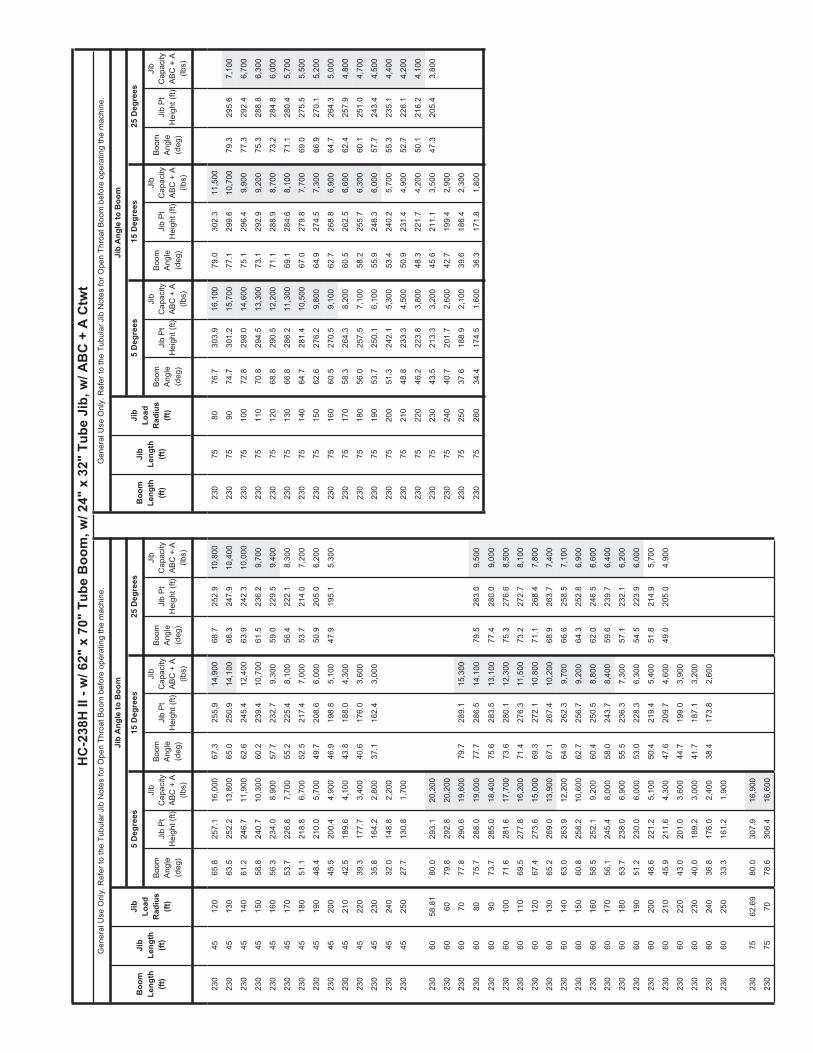
Boom
Ang
le(d
eg)
Jib
Pt
Hei
ght (
ft)
Boom
Ang
le(d
eg)
Jib
Pt
Hei
ght (
ft)Ji
b P
t H
eigh
t (ft)
Jib
Pt
Hei
ght (
ft)Ji
b P
t H
eigh
t (ft)
Boo
mLe
ngth
(ft)
Jib
Leng
th(ft
)
Jib
Load
Rad
ius
(ft)
Boom
Ang
le(d
eg)
Boom
Ang
le(d
eg)
Boom
Ang
le(d
eg)
HC
-238
H II
- w
/ 62"
x 7
0" T
ube
Boo
m, w
/ 24"
x 3
2" T
ube
Jib,
w/ A
BC
+ A
Ctw
t
25 D
egre
es15
Deg
rees
5 D
egre
es5
Deg
rees
15 D
egre
es25
Deg
rees
Jib
Ang
le to
Boo
m
Jib
Cap
acity
ABC
+ A
(lb
s)
Jib
Cap
acity
ABC
+ A
(lb
s)
Jib
Cap
acity
ABC
+ A
(lb
s)
Jib
Pt
Hei
ght (
ft)
Gen
eral
Use
Onl
y. R
efer
to th
e Tu
bula
r Jib
Not
es fo
r Ope
n Th
roat
Boo
m b
efor
e op
erat
ing
the
mac
hine
.
Boom
Ang
le(d
eg)
Boo
mLe
ngth
(ft)
Jib
Leng
th(ft
)
Jib
Load
Rad
ius
(ft)
Gen
eral
Use
Onl
y. R
efer
to th
e Tu
bula
r Jib
Not
es fo
r Ope
n Th
roat
Boo
m b
efor
e op
erat
ing
the
mac
hine
.
Jib
Ang
le to
Boo
m
Jib
Cap
acity
ABC
+ A
(lb
s)
Jib
Cap
acity
ABC
+ A
(lb
s)
Jib
Cap
acity
ABC
+ A
(lb
s)
230
4512
065
.825
7.1
16,0
0067
.325
5.9
14,9
0068
.725
2.9
10,8
0023
075
8076
.730
3.9
16,1
0079
.030
2.3
11,5
00
230
4513
063
.525
2.2
13,8
0065
.025
0.9
14,1
0066
.324
7.9
10,4
0023
075
9074
.730
1.2
15,7
0077
.129
9.6
10,7
0079
.329
5.6
7,10
0
230
4514
061
.224
6.7
11,9
0062
.624
5.4
12,4
0063
.924
2.3
10,0
0023
075
100
72.8
298.
014
,600
75.1
296.
49,
900
77.3
292.
46,
700
230
4515
058
.824
0.7
10,3
0060
.223
9.4
10,7
0061
.523
6.2
9,70
023
075
110
70.8
294.
513
,300
73.1
292.
99,
200
75.3
288.
86,
300
230
4516
056
.323
4.0
8,90
057
.723
2.7
9,30
059
.022
9.5
9,40
023
075
120
68.8
290.
512
,200
71.1
288.
98,
700
73.2
284.
86,
000
230
4517
053
.722
6.8
7,70
055
.222
5.4
8,10
056
.422
2.1
8,30
023
075
130
66.8
286.
211
,300
69.1
284.
68,
100
71.1
280.
45,
700
230
4518
051
.121
8.8
6,70
052
.521
7.4
7,00
053
.721
4.0
7,20
023
075
140
64.7
281.
410
,500
67.0
279.
87,
700
69.0
275.
55,
500
230
4519
048
.421
0.0
5,70
049
.720
8.6
6,00
050
.920
5.0
6,20
023
075
150
62.6
276.
29,
800
64.9
274.
57,
300
66.9
270.
15,
200
230
4520
045
.520
0.4
4,90
046
.919
8.8
5,10
047
.919
5.1
5,30
023
075
160
60.5
270.
59,
100
62.7
268.
86,
900
64.7
264.
35,
000
230
4521
042
.518
9.6
4,10
043
.818
8.0
4,30
023
075
170
58.3
264.
38,
200
60.5
262.
56,
600
62.4
257.
94,
800
230
4522
039
.317
7.7
3,40
040
.617
6.0
3,60
023
075
180
56.0
257.
57,
100
58.2
255.
76,
300
60.1
251.
04,
700
230
4523
035
.816
4.2
2,80
037
.116
2.4
3,00
023
075
190
53.7
250.
16,
100
55.9
248.
36,
000
57.7
243.
44,
500
230
4524
032
.014
8.8
2,20
023
075
200
51.3
242.
15,
300
53.4
240.
25,
700
55.3
235.
14,
400
230
4525
027
.713
0.8
1,70
023
075
210
48.8
233.
34,
500
50.9
231.
44,
900
52.7
226.
14,
200
230
7522
046
.222
3.8
3,80
048
.322
1.7
4,20
050
.121
6.2
4,10
0
230
6058
.81
80.0
293.
120
,200
230
7523
043
.521
3.3
3,20
045
.621
1.1
3,50
047
.320
5.4
3,80
0
230
6060
79.8
292.
820
,200
230
7524
040
.720
1.7
2,60
042
.719
9.4
2,90
0
230
6070
77.8
290.
619
,600
79.7
289.
115
,300
230
7525
037
.618
8.9
2,10
039
.618
6.4
2,30
0
230
6080
75.7
288.
019
,000
77.7
286.
514
,100
79.5
283.
09,
500
230
7526
034
.417
4.5
1,60
036
.317
1.8
1,80
0
230
6090
73.7
285.
018
,400
75.6
283.
513
,100
77.4
280.
09,
000
230
6010
071
.628
1.6
17,7
0073
.628
0.1
12,3
0075
.327
6.6
8,50
0
230
6011
069
.527
7.8
16,2
0071
.427
6.3
11,5
0073
.227
2.7
8,10
0
230
6012
067
.427
3.6
15,0
0069
.327
2.1
10,8
0071
.126
8.4
7,80
0
230
6013
065
.226
9.0
13,9
0067
.126
7.4
10,2
0068
.926
3.7
7,40
0
230
6014
063
.026
3.9
12,2
0064
.926
2.3
9,70
066
.625
8.5
7,10
0
230
6015
060
.825
8.2
10,6
0062
.725
6.7
9,20
064
.325
2.8
6,90
0
230
6016
058
.525
2.1
9,20
060
.425
0.5
8,80
062
.024
6.5
6,60
0
230
6017
056
.124
5.4
8,00
058
.024
3.7
8,40
059
.623
9.7
6,40
0
230
6018
053
.723
8.0
6,90
055
.523
6.3
7,30
057
.123
2.1
6,20
0
230
6019
051
.223
0.0
6,00
053
.022
8.3
6,30
054
.522
3.9
6,00
0
230
6020
048
.622
1.2
5,10
050
.421
9.4
5,40
051
.821
4.9
5,70
0
230
6021
045
.921
1.6
4,30
047
.620
9.7
4,60
049
.020
5.0
4,90
0
230
6022
043
.020
1.0
3,60
044
.719
9.0
3,90
0
230
6023
040
.018
9.2
3,00
041
.718
7.1
3,20
0
230
6024
036
.817
6.0
2,40
038
.417
3.8
2,60
0
230
6025
033
.316
1.2
1,90
0
230
7562
.69
80.0
307.
916
,900
230
7570
78.6
306.
416
,600

5637 (supersedes 5503)-0613-H9
Link−Belt Construction Equipment Company Lexington, Kentucky www.linkbelt.com�Link−Belt is a registered trademark. Copyright 2013. We are constantly improving our products and therefore reserve the right to change designs and specifications.