specifying quartz crystals
TRANSCRIPT

Specifying Quartz Crystals
Topics covered
2
What is a Quartz Crystal
Typical quartz crystal specification
Frequency
Model
Frequency Stability
Frequency Tolerances & Stabilities
Operating Temperature Range
Load Condition
Overtone Order
Additional Text Code
Packaging Codes
Outline Drawings
Marking
3
Quartz crystals
4
Quartz crystals are the most technically
simple product we offer.
Package contains a quartz wafer; all the
supporting circuitry needed to create
the oscillation must be provided by the
customer’s circuit.
The quartz wafer is cut and shaped to
give a resonant frequency within the
specified limits.
Our quartz crystal part numbers all
contain the code XTAL.
5
The electrical parameters are given on
the specification to facilitate the
correct circuit design.
Our Application Support team can
provide assistance if required.
The limits given in the following
specifications are indicative of the
standard crystal design.
In the event that a specification is
needed which is outside the standard
crystal designs offered please contact
our Sales team.
6
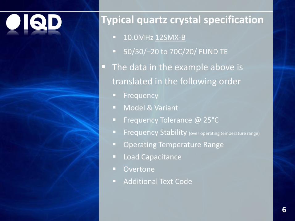
10.0MHz 12SMX-B
50/50/–20 to 70C/20/ FUND TE
The data in the example above is
translated in the following order
Frequency
Model & Variant
Frequency Tolerance @ 25°C
Frequency Stability (over operating temperature range)
Operating Temperature Range
Load Capacitance
Overtone
Additional Text Code
Typical quartz crystal specification
Frequency
7
Frequency is normally specified in
kilohertz (kHz) up to 999.999kHz and in
megahertz (MHz) from 1.0MHz.
All IQD’s computer-generated
transaction documents follow this
standard convention automatically.
Frequency should be described to
seven significant figures
If seven significant figures are not used,
we assume that any figure that might
follow those given may be taken as zero
e.g. frequency given as 16.6MHz will be
taken as 16.60, not 16.6666.
8
Some specifiers extend the use of kHz
to all crystals operating in fundamental
mode, reserving MHz for overtones,
this method is not used by IQD.
To minimise the possibility of
misunderstanding it is best to use the
standard method and specify
fundamental or overtone mode
separately.
Please contact one of our sales offices
for details of developed frequencies.
Model
9
Before manufacturing starts the model must be defined.
Each model covers a frequency range which is defined in the specification.
Model information should also cover any mechanical variants i.e. top wire, cropped leads etc.
Thru-hole versions have the following variants available, either singly or in some cases, in combination: 3 lead base
Top wire
Insulating sleeve
Fitted insulator
Cropped leads
Formed leads
Frequency Tolerance
10
Cost of manufacture depends partly on
the accuracy required at reference
temperature (which in the case of the
AT-cut crystal, is usually 25°C).
Where high initial accuracy is important
the additional manufacturing cost
should be weighed against the cost of
including a frequency trimming facility
within the oscillator circuit design.
Frequency Stability
11
Normally specified as a frequency
variation over a defined operating
temperature range with respect to the
frequency at reference temperature.
Temperature ranges are defined for
each crystal in the relevant data sheet.
The majority of crystals will continue to
operate quite satisfactorily outside the
temperature range for which they are
specified, but with a possible
degradation in the frequency stability.
Under normal conditions this will not
damage the crystal.
12
A crystal designed for operation over a
restricted operating temperature
range, (such as from 0 to 50°C)
generally has a better frequency
stability over that range than one
designed for operation over a wide
operating temperature range.
Therefore it’s important not to over
specify the temperature range, as
doing so will result in inferior
performance for the same or greater
cost; or greater cost for the same or
inferior performance.
13
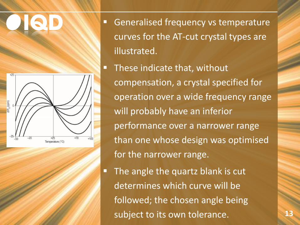
Generalised frequency vs temperature
curves for the AT-cut crystal types are
illustrated.
These indicate that, without
compensation, a crystal specified for
operation over a wide frequency range
will probably have an inferior
performance over a narrower range
than one whose design was optimised
for the narrower range.
The angle the quartz blank is cut
determines which curve will be
followed; the chosen angle being
subject to its own tolerance.
14
Since manufacturing cost is tolerance
dependent it’s wise not to specify a
wider operating temperature range
than is actually needed unless some
sacrifice of stability, or an increase in
cost, can be accepted.
Frequency Tolerances & Stabilities
15
Standard tolerances and stabilities:
±5ppm
±10ppm
±15ppm
±20ppm
±30ppm
±50ppm
±100ppm
Operating Temperature Ranges
16
Standard operating temperature
ranges:
0 to 50°C
–10 to 60°C
–20 to 70°C
–30 to 80°C
–40 to 85°C
–55 to 105°C
–55 to 125°C
Load Condition
17
Letters ‘SR’ are used to denote
calibration of the crystal at Series
Resonance.
If it is to be calibrated at load
resonance the characters represent the
circuit load capacitance in pF.
Overtone Order
18
Quartz crystals resonate in specific
“modes” depending upon the
frequency in question and oscillator
circuit configuration in which it is used.
The main mode of operation is called
“fundamental”. i.e. 10MHz crystal
vibrates at a frequency of 10MHz
For high frequency use, quartz crystals
can be made to operate at odd
multiples of its fundamental frequency.
These multiples are termed
“overtones” and are denoted by their
multiple as: 3rd, 5th, 7th, 9th.
19
e.g. 10MHz crystal can be made to
operate at 3rd overtone which is
approx 3 times its fundamental
frequency.
If an overtone mode crystal is chosen
then the circuit design must include the
relevant components required to
suppress the fundamental mode of
operation to ensure oscillation at the
intended frequency.
Where there is a cross-over band in the
modes available, the mode required
must be specified when ordering.
20
For general use and simplicity of circuit
design we recommend that
fundamental mode be chosen where
possible.
Additional Text Code
21
If product is non-standard, the letter ‘T’
will appear at the end of the product
specification.
This refers to additional text on the
data sheet to identify the non-standard
elements of the specification.
Packaging Codes
22
Code is given after the part number i.e.
LFXTAL012345Bulk &
LFXTAL012345Reel, these are the same
part but packaged loose (Bulk) and tape
and reel (Reel).
Unless individual data sheets state Bulk
packaging, SMD parts will be Tape &
Reel packed.
Only complete reels are sold
Packaging options Bulk = Bulk packed Reel = Tape and reel packed
Tray = Tray packed (option for some products)
Outline Drawings
23
All dimensions are shown in mm and
are nominal unless otherwise stated.
Marking
24
Due to the small size of modern SMT
devices many components are not
marked with any readable information
beyond the pad 1 denominator.
In these cases the marking will be
production specific data.
More information can be found on our
website.

Standing out from the crowd
25