speckle free laser projection - optotune.com application note for... · beam projection optics...
TRANSCRIPT
Speckle free laser projection With Optotune’s Laser Speckle Reducer
October 2013 Dr. Selina Casutt, Application Engineer Bernstrasse 388 | CH-8953 Dietikon | Switzerland Phone +41 58 856 3011 | www.optotune.com | [email protected]

This information is confidential to Optotune and is not to be copied or forwarded to any 3rd party without our prior written consent.
Speckle-free laser projection with an LSR-axicon-integrator rod combination
1
• A great speckle reduction can be achieved with a configuration described in this document with
- an axicon as a focusing lens
- Optotune’s LSR
- directly followed by a beam homogenizer
• Such a setup is compact, cost-saving and easy to align
Red Laser
Green Laser
Blue Laser
Beam combiner
Collimation lenses
Collecting lens
Beam homogenizer
Optotune LSR
DLP/LCOS
Projection Optics
Homogen, collimated, speckle free
beam
Fiber
Optotune’s LSR
Red Laser
Green Laser
Blue Laser
Beam combiner
Collimation lenses
Collecting lens
Beam homogenizer
Optotune LSR
DLP/LCOS
Projection Optics
Homogen, collimated, speckle free
beam
Projection optics
DLP/LCOS Beam
homogenizer
Collimation optics
Homogenous, speckle-free beam Axicon
This information is confidential to Optotune and is not to be copied or forwarded to any 3rd party without our prior written consent.
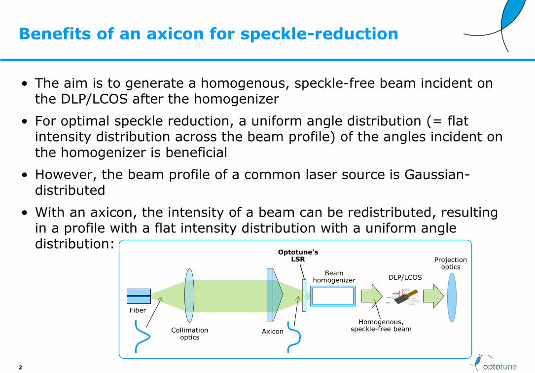
Benefits of an axicon for speckle-reduction
• The aim is to generate a homogenous, speckle-free beam incident on the DLP/LCOS after the homogenizer
• For optimal speckle reduction, a uniform angle distribution (= flat intensity distribution across the beam profile) of the angles incident on the homogenizer is beneficial
• However, the beam profile of a common laser source is Gaussian-distributed
• With an axicon, the intensity of a beam can be redistributed, resulting in a profile with a flat intensity distribution with a uniform angle distribution:
2
Red Laser
Green Laser
Blue Laser
Beam combiner
Collimation lenses
Collecting lens
Beam homogenizer
Optotune LSR
DLP/LCOS
Projection Optics
Homogen, collimated, speckle free
beam
Fiber
Optotune’s LSR
Red Laser
Green Laser
Blue Laser
Beam combiner
Collimation lenses
Collecting lens
Beam homogenizer
Optotune LSR
DLP/LCOS
Projection Optics
Homogen, collimated, speckle free
beam
Projection optics
DLP/LCOS Beam
homogenizer
Collimation optics
Homogenous, speckle-free beam Axicon
This information is confidential to Optotune and is not to be copied or forwarded to any 3rd party without our prior written consent.
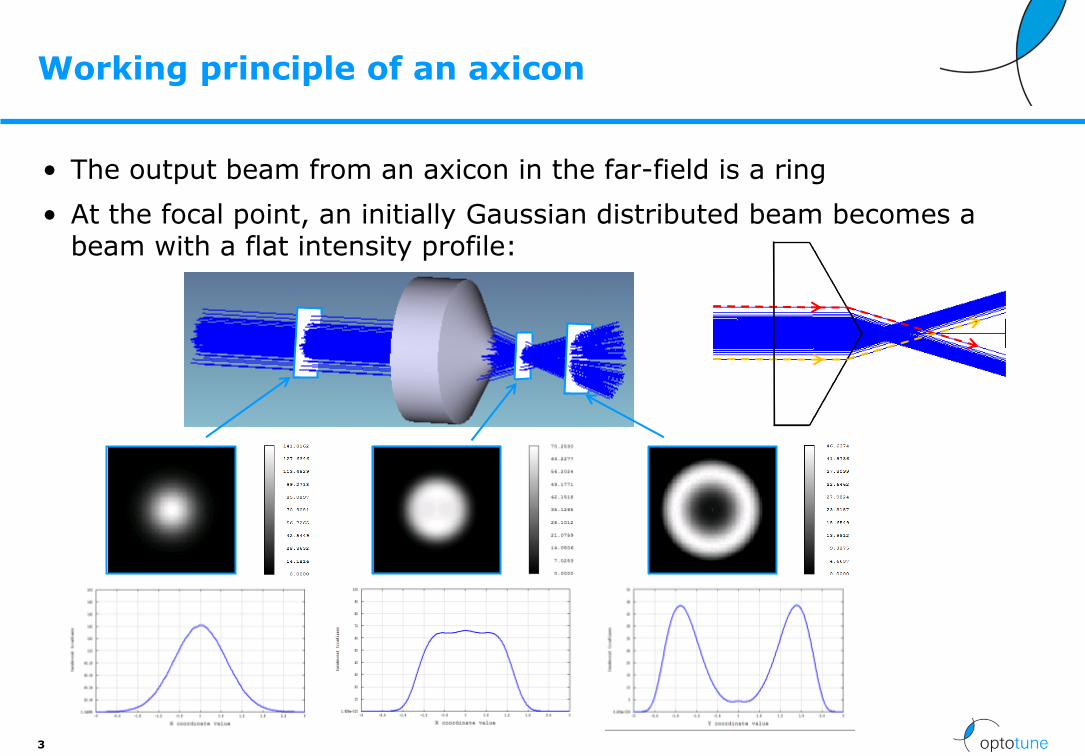
• The output beam from an axicon in the far-field is a ring
• At the focal point, an initially Gaussian distributed beam becomes a beam with a flat intensity profile:
Working principle of an axicon
3
This information is confidential to Optotune and is not to be copied or forwarded to any 3rd party without our prior written consent.
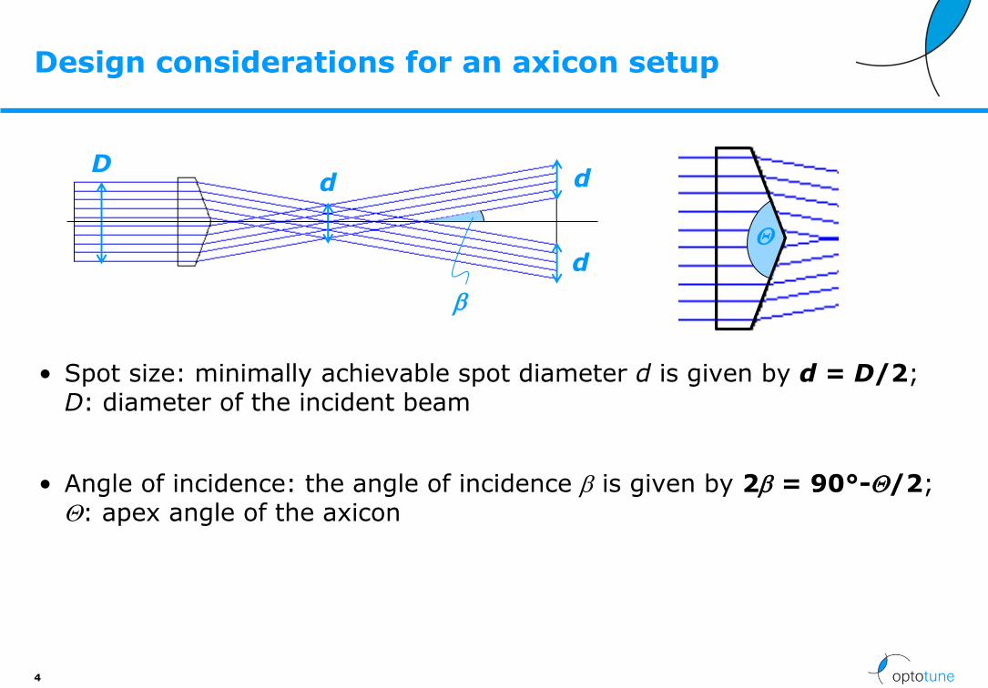
Design considerations for an axicon setup
• Spot size: minimally achievable spot diameter d is given by d = D/2; D: diameter of the incident beam
• Angle of incidence: the angle of incidence b is given by 2b = 90°-Q/2; Q: apex angle of the axicon
4
D d
d
d
b
Q

This information is confidential to Optotune and is not to be copied or forwarded to any 3rd party without our prior written consent.
Exemplary setup (1/2)
5
This information is confidential to Optotune and is not to be copied or forwarded to any 3rd party without our prior written consent.
Fiber
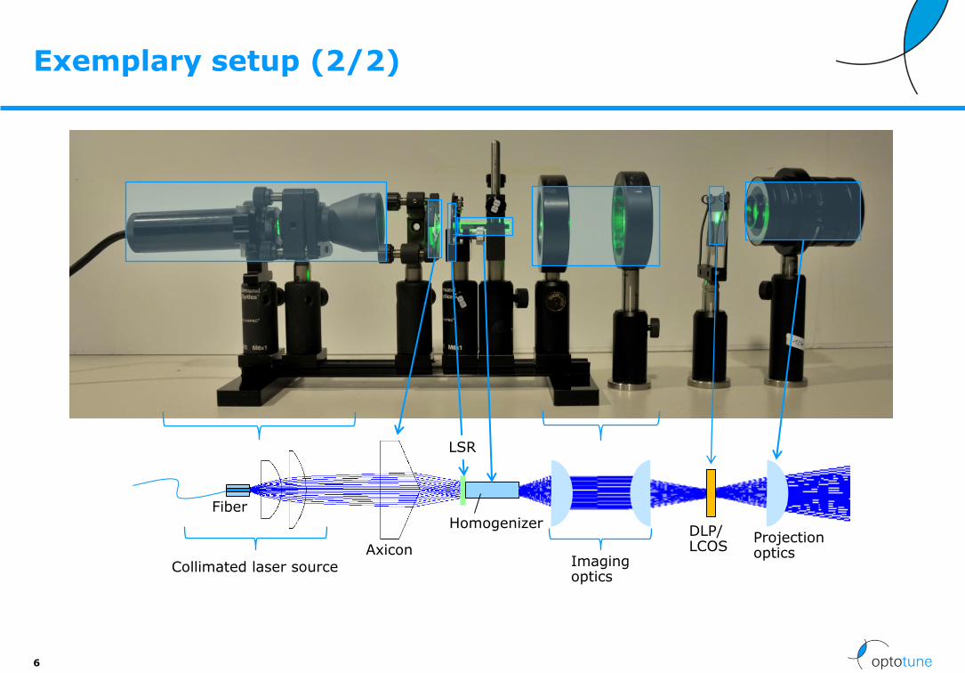
Exemplary setup (2/2)
6
Collimated laser source Axicon
Homogenizer Projection optics
DLP/ LCOS
LSR
Imaging optics
This information is confidential to Optotune and is not to be copied or forwarded to any 3rd party without our prior written consent.
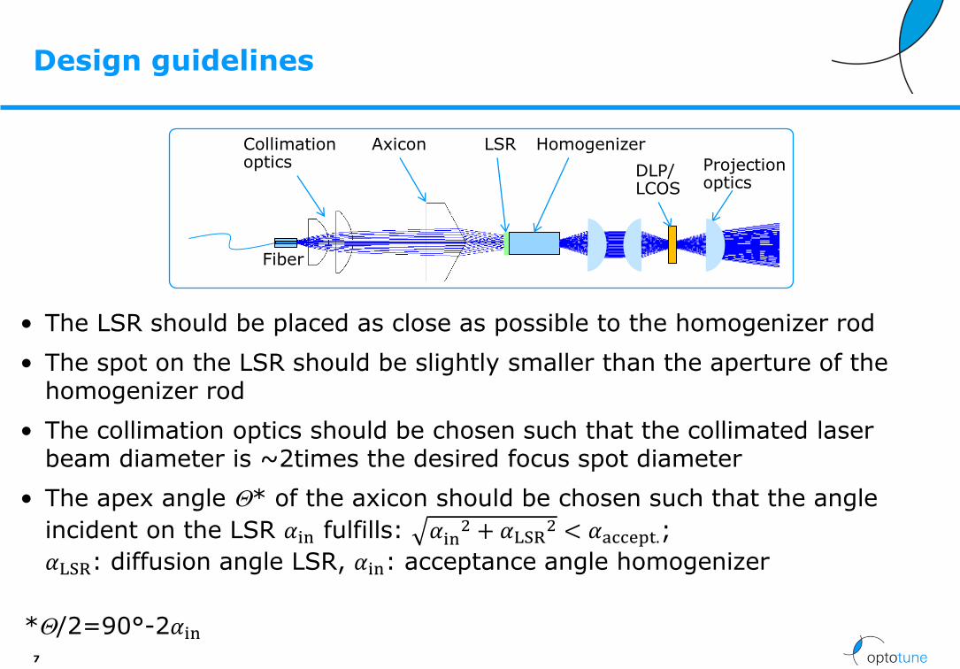
Design guidelines
• The LSR should be placed as close as possible to the homogenizer rod
• The spot on the LSR should be slightly smaller than the aperture of the homogenizer rod
• The collimation optics should be chosen such that the collimated laser beam diameter is ~2times the desired focus spot diameter
• The apex angle Q* of the axicon should be chosen such that the angle
incident on the LSR 𝛼in fulfills: 𝛼in2 + 𝛼LSR
2 < 𝛼accept.;
𝛼LSR: diffusion angle LSR, 𝛼in: acceptance angle homogenizer
7
*Q/2=90°-2𝛼in
Collimation optics
Axicon
Fiber
LSR Homogenizer
Projection optics
DLP/LCOS
This information is confidential to Optotune and is not to be copied or forwarded to any 3rd party without our prior written consent.
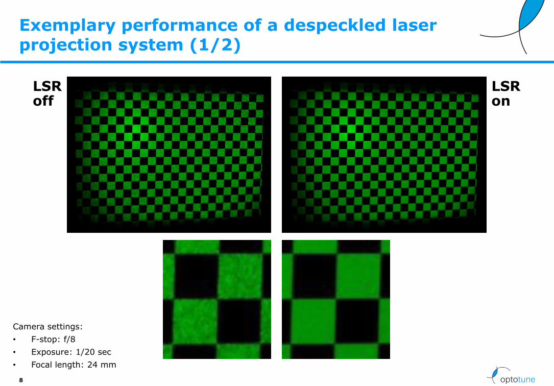
Exemplary performance of a despeckled laser projection system (1/2)
8
Camera settings:
• F-stop: f/8
• Exposure: 1/20 sec
• Focal length: 24 mm
LSR off
LSR on
This information is confidential to Optotune and is not to be copied or forwarded to any 3rd party without our prior written consent.
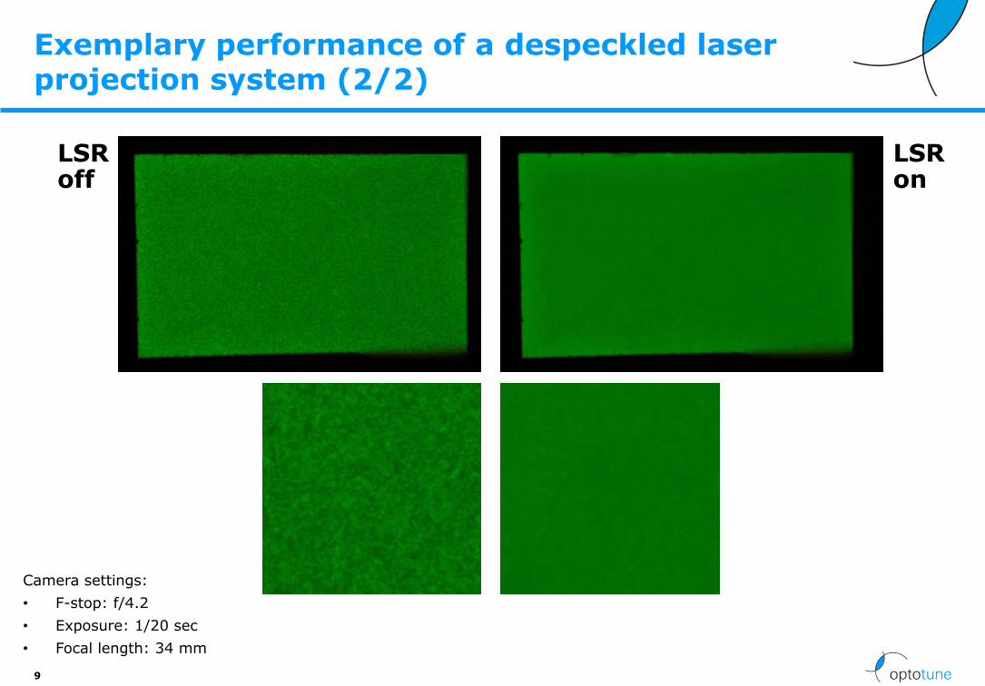
Exemplary performance of a despeckled laser projection system (2/2)
9
Camera settings:
• F-stop: f/4.2
• Exposure: 1/20 sec
• Focal length: 34 mm
LSR off
LSR on
This information is confidential to Optotune and is not to be copied or forwarded to any 3rd party without our prior written consent.
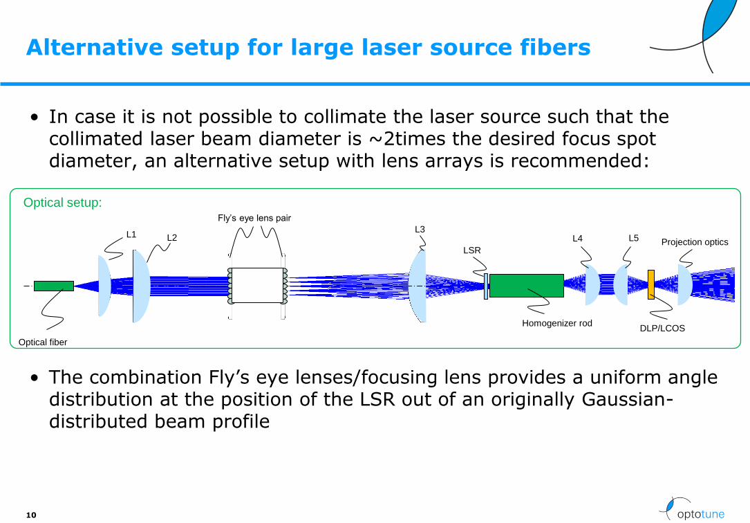
• In case it is not possible to collimate the laser source such that the collimated laser beam diameter is ~2times the desired focus spot diameter, an alternative setup with lens arrays is recommended:
• The combination Fly’s eye lenses/focusing lens provides a uniform angle distribution at the position of the LSR out of an originally Gaussian-distributed beam profile
Alternative setup for large laser source fibers
10
Optical fiber
Fly’s eye lens pair
Homogenizer rod
L3
Optical setup:
L1
LSR
L2
DLP/LCOS
Projection optics L4 L5
This information is confidential to Optotune and is not to be copied or forwarded to any 3rd party without our prior written consent.
Despeckling screen – reducing the subjective speckles
• The configuration described above reduces the objective speckles
• For reduction of the subjective speckles, Optotune provides a passive subjective speckle reducing screen with a specially designed surface structure, enabling the removal of subjective speckles
• Working principle: The microstructure of the screen introduces a spatially varying phase shift for different spatial parts of the illuminating beam. When the distance between the screen and the observer is large enough, a sufficient number of independent beam parts with differing phases are superimposed in the observers imaging system (e.g. eye) and the speckle pattern is smeared out, resulting in a reduced speckle contrast.
• Please contact us for further information and for screen samples to test in your setup
11

This information is confidential to Optotune and is not to be copied or forwarded to any 3rd party without our prior written consent.
Difference between subjective and objective speckles
• Objective speckles are formed when coherent light from the laser source is scattered by a projection optics and interferes on the projection screen. Thus, the interference pattern on the projection screen is made up of contributions from all scatterings from the projection optics and the structure of the screen. The resulting speckle pattern on the projection screen stays the same, regardless of how or from which direction the projection screen is viewed.
• In contrast, in the case of subjective speckles, the scattered light from the projection screen is imaged by an imaging system (e.g., the human eye) onto an imaging surface (e.g., the retina). Here, the detailed structure of the speckle pattern on the imaging surface depends on imaging parameters such as, e.g., imaging direction, aperture, or resolving power of the imaging system.
12

This information is confidential to Optotune and is not to be copied or forwarded to any 3rd party without our prior written consent.
Optotune – 1 slide
Optotune AG Bernstrasse 388 CH-8953 Dietikon Switzerland
Phone: +41 58 856 3000 | Fax: +41 58 856 3001
www.optotune.com | [email protected]