spectra series™ and 8000-line motor control centers...
TRANSCRIPT

Spectra Series™ and 8000-LineMotor Control Centers Application Data
J1
➀ Open, Type K, general purpose, NEMA SF, solid base, rolled-steel-shell, GEinduction motors.
Note: The listed data is based on approximate full-load current ratings of stan-dard, open, 1.15 service factor, continuous rated General Electric motors.Full-load current ratings of similar motors of other manufacturers may varyconsiderably. Therefore, whenever possible use actual full-load current rat-ing given on motor nameplate. Contact motor manufacturer for full-loadcurrents of single-phase and DC motors.
Average Expected ValuesMotor Synchronous of Full-load Currents
HP Speed, RPM 200V 230V 460V 575V1800 1.6 1.4 0.70 0.56
1⁄4➀1200 1.7 1.5 0.75 0.603600 2.0 1.7 0.85 0.68
1⁄2➀ 1800 1.7 1.5 0.75 0.601200 2.0 1.7 0.85 0.683600 2.0 1.8 0.88 0.701800 2.3 2.0 1.0 0.80
1⁄21200 2.3 2.0 1.0 0.80900 3.2 2.8 1.4 1.43600 2.8 2.4 1.2 0.961800 3.2 2.8 1.4 1.1
3⁄4 1200 3.7 3.2 1.6 1.3900 4.4 3.8 1.9 1.53600 3.7 3.2 1.6 1.31800 4.1 2.2 1.6 1.4
11200 4.4 4.6 2.3 1.5900 5.5 4.8 2.4 1.93600 5.3 4.8 2.4 1.81800 6.0 4.4 2.2 2.1
11⁄21200 6.0 4.6 2.3 2.1900 7.1 6.2 3.1 2.53600 6.9 6.0 3.0 2.41800 7.1 5.8 2.9 2.5
21200 7.6 6.2 3.1 2.6900 10.6 9.2 4.6 3.73600 9.4 8.0 4.0 3.31800 9.9 7.9 3.9 3.4
31200 12.0 8.6 4.3 4.2900 15.4 13.4 6.7 5.43600 15.4 12.2 6.1 5.41800 14.4 12.6 6.3 5.7
51200 19.3 14.0 7.0 6.7900 19.8 17.2 8.6 6.93600 21.4 18.0 9.0 7.51800 23.7 18.0 9.3 8.2
71⁄2 1200 26.0 19.8 9.9 9.0900 28.5 24.0 12.4 9.93600 27.4 24.0 12.0 9.51800 27.0 23.8 11.9 10.9
101200 32.7 25.8 12.9 11.4900 33.1 28.8 14.4 11.53600 42.6 36.0 18.0 14.81800 40.3 35.0 17.6 16.2
151200 45.1 33.0 19.1 15.7900 47.6 41.4 20.7 16.63600 62.3 45.4 22.7 21.71800 53.2 46.2 23.1 20.6
20 1200 56.6 50.0 25.0 19.7900 63.9 55.6 27.8 22.2
Average Expected ValuesMotor Synchronous of Full-load Currents
HP Speed, RPM 200V 230V 460V 575V3600 72.0 56.0 28.0 25.01800 71.3 60.0 30.0 24.8
251200 73.8 63.2 31.6 25.7900 82.6 71.8 35.9 28.73600 85.6 67.8 33.9 29.81800 81.7 71.2 35.6 29.9
301200 88.6 73.8 36.9 30.8900 92.2 80.2 40.1 32.13600 101 89.0 44.6 39.21800 112 97.8 48.9 40.3
401200 114 99.6 48.5 39.8900 122 105.8 52.9 42.33600 140 129 64.5 48.91800 142 122 61.1 49.4
501200 144 125.2 61.0 50.1900 159 138.2 69.1 55.33600 163 145.6 72.8 56.61800 172 147.4 73.7 59.9
601200 172 149.2 69.8 59.7900 176 153.4 76.7 61.43600 206 181 90.5 71.51800 207 180.0 91.6 72.0
751200 206 179.2 86.7 71.7900 221 191.8 95.9 76.73600 262 238 119 91.21800 281 232 116 97.7
1001200 283 246 118 98.4900 296 258 129 1033600 338 290 139 1161800 340 296 143 118
1251200 352 306 149 122900 370 322 161 1293600 398 346 164 1381800 412 348 169 143
1501200 419 364 177 146900 435 378 189 1513600 – 446 217 178
200 1800 – 468 226 1871200 – 482 239 1933600 – 574 287 230
250 1800 – 590 295 2361200 – 594 297 2383600 – 676 338 270
300 1800 – 686 340 2743600 – 774 387 310
350 1800 – 792 396 317400 3600 – 890 445 356
Approximate Motor Full-Load Current RatingsFull-Load Current for EPAC Compliant MotorsAverage Expected ValuesFor three-phase, 60 Hertz, GE Type KE (NEMA Design B) drip-proof, normal starting torque, continuous 40°C ambient (1.15 serv-ice factor) horizontal induction motors.

Spectra Series™ and 8000-LineMotor Control Centers Application Data
J2
J
Spectra RMS Circuit Breaker Current Ratings
Mag-Break Magnetic Circuit Breaker Trip Set Positions
Cat No. Continuous Trip Setting Positions3 Pole Amperes Lo 2 4 6 8 10 Hi
TEC36003 3 8 13 18 23 28 33 38TEC36007 7 18 30 42 54 66 78 90TEC36015 15 42 68 94 120 146 172 198TEC36030 30 90 140 190 240 290 340 390TEC36050 50 180 260 340 420 500 580 660TEC36100 100 300 468 636 804 972 1140 1300TEC36150 150 600 950 1300 1650 2000 2350 2700TFC36225 225 600 780 1020 1200 1400
TFC36225A 225 1000 1200 1630 1920 2250TJC36400B 400 1200 1400 1850 3250 4000TJC36400E 400 330 435 600 860 1100TJC36400F 400 550 720 945 1280 1670TJC36400G 400 1000 1280 1780 2360 3300TJC36600G 600 1000 1280 1780 2360 3300TJC36600H 600 1800 2100 2600 3600 6000
Max. Rating Instantaneous Trip Setting, Nominal RMS Sym. AmperesFrame Frame Plug Trip Setting Adjustment Position
Amps Amps Min. 2 3 4 5 6 Max.
73 11 13 16 19 24 31 397 22 27 35 43 56 71 9015 43 55 69 86 111 143 182
3020 58 74 93 116 151 196 25425 73 93 117 147 193 253 33230 87 112 142 179 237 314 41540 118 150 188 237 308 394 501
SE 60 50 148 187 236 296 386 498 63760 178 224 284 355 464 604 77770 206 261 329 411 534 684 863
100 80 236 299 377 472 614 787 99990 267 338 426 532 694 892 1,138100 297 376 475 593 775 998 1,280110 328 415 524 654 857 1,105 1,426
150 125 374 474 598 745 979 1,265 1,640150 450 570 720 897 1,181 1,528 1,991
Min. 2 3 4 5 Max.70 205 260 330 410 535 70090 265 335 425 530 690 900100 295 375 470 590 765 1,000110 325 410 520 650 845 1,100
SF 250 125 370 465 570 740 960 1,250150 440 560 705 885 1,150 1,500175 515 655 825 1,035 1,345 1,750200 590 750 940 1,180 1,535 2,000225 665 840 1,050 1,330 1,730 2,250250 740 935 1,180 1,480 1,920 2,500125 380 480 620 765 990 1,275150 455 575 740 920 1,185 1,530175 530 670 865 1,070 1,385 1,785200 605 765 990 1,225 1,580 2,040
400 225 680 860 1,115 1,375 1,780 2,295250 755 955 1,235 1,530 1,975 2,550300 905 1,145 1,480 1,835 2,370 3,060350 1,060 1,340 1,730 2,140 2,765 3,570
SG 400 1,210 1,530 1,980 2,445 3,160 4,080250 765 965 1,215 1,500 1,960 2,530300 915 1,155 1,455 1,800 2,355 3,035350 1,070 1,350 1,700 2,100 2,745 3,545
600 400 1,200 1,540 1,940 2,400 3,135 4,050450 1,375 1,735 2,185 2,695 3,530 4,555500 1,525 1,925 2,425 2,995 3,920 5,060600 1,830 2,310 2,910 3,595 4,705 6,075300 940 1,150 1,445 1,795 2,375 3,015400 1,255 1,535 1,930 2,395 3,165 4,015
800 500 1,570 1,915 2,410 2,990 3,955 5,020600 1,875 2,290 2,895 3,610 4,740 6,195700 2,155 2,665 3,375 4,240 5,525 7,420
SK 800 2,440 3,035 3,860 4,875 6,305 8,705600 1,825 2,310 2,905 3,685 4,730 6,110700 2,125 2,695 3,390 4,300 5,515 7,125
1,200 800 2,430 3,080 3,870 4,910 6,305 8,1451,000 3,040 3,850 4,840 6,140 8,880 10,1801,200 3,650 4,620 5,805 7,370 9,455 12,215
The greatest degree of protection is provided when the magnetictrip setting is just above the motor starting inrush current. It istherefore recommended that the magnetic trip position beadjusted to a setting one position higher than the setting that
carries the motor starting current. For recommended continuous-current ratings, see overload heater tables on pages J-7 throughJ-15.
Spectra Series™ and 8000-LineMotor Control Centers Application Data
J3
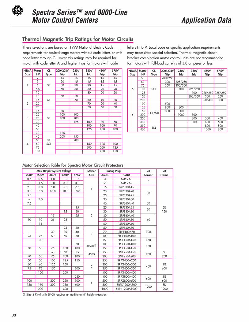
Thermal Magnetic Trip Ratings for Motor CircuitsThese selections are based on 1999 National Electric Coderequirements for squirrel-cage motors without code letters or withcode letter through G. Lower trip ratings may be required formotor with code letter A and higher trips for motors with code
letters H to V. Local code or specific application requirementsmay necessitate special selection. Thermal-magnetic circuitbreaker combination motor control units are not recommendedfor motors with full-load currents of 3.8 amperes or less.
NEMA Motor CB 200/208V 230V 380V 460V 575VSize HP Type Trip Trip Trip Trip Trip
2 15 15 15 15 153 20 15 15 15 15
1 5 SE 30 30 20 15 157.5 50 30 30 20 2010 30 20 2010 50 5015 SE 70 50 40 30
2 20 70 50 4025 70 60 5015 7020 100 100
3 25 SE 100 10030 125 100 70 5040 100 100 7050 125 100 10030 12540 200 15050 SF 200
4 60 SGL 150 125 10075 200 200 125100 200 150
NEMA Motor CB 200/208V 230V 380V 460V 575VSize HP Type Trip Trip Trip Trip Trip
50 200/25060 300 225/25075 350 300/350
5 100 SGL 400 225/250125 300 225/250 225/250150 300/350 300 250200 350/400 300100 500125 800 800150 800 800
6 200 SGL/SKL 1000 500250 800 500 400300 800 600 500350
SKL800 800
400 1000 800
➀ Size 4 RVAT with SF CB requires an additional 6” height extension.
Motor Selection Table for Spectra Motor Circuit ProtectorsMax HP per System Voltage Starter Rating Plug CB CB
208V 230V 380V 460V 575V Size Amps CAT# Sensor Frame0.5 0.5 1.0 1.0 1.5 3 SRPE7A31.0 1.5 3.0 3.0 3.0 7 SRPE7A7
7
2.0 3.0 5.0 5.0 7.51
15 SRPE30A153.0 5.0 10.0 10.0 10.0 20 SRPE30A205.0 25 SRPE30A25
30
– 7.5 30 SRPE30A307.5 40 SRPE60A40 60
15 25 SRPE30A25 SE15 20 30 SRPE30A30
30150
15 25 2 40 SRPE60A4010 10 25 25 50 SRPE60A50 60
15 60 SRPE60A6025 30 50 SRPE60A50
30 30 403
70 SRPE100A70 10025 25 50 50 50 100 SRPE100A100
30 150 SRPE150A150 15060 100 SRPE150A100
40 50 75 100 1004RVAT➀
150 SRPE150A150150
60 60 75 150 SRPF250A150 SF40 50 75 100 100
4STD200 SRPF250A200
200250
50 50 100 125 150 250 SRPG400A25060 60 125 150 300 SRPG400A300
400SG
75 75 150 2005
350 SRPG400A350 600100 200 400 SRPG400A400
250 400 SRPG800A400 SG100 200 250 300 500 SRPG800A500
600600
150 150 300 350 4006
800 SRPK1200A8001200
SK200 400 1000 SRPK1200A1000 1200

Spectra Series™ and 8000-LineMotor Control Centers Application Data
J4
J
Overload Heater TablesHeaters for Ther-Mag ControllersFor continuous rated motors with a service factor of 1.15 to1.25, select heaters from the heater table. For continuous ratedmotors with a service factor of 1.0, multiply the motor full-loadcurrent by 0.9 and use this value to select heaters.
Overload relay tripping current in 40°C ambient is the mini-mum value of full load current multiplied by 1.25.
WARNING: Overload relays with automatic reset may auto-matically start a motor connected to a 2-wire control circuit.When automatic restarting is not desired, use a 3-wire control circuit.
Provide short circuit protection in accordance with the NationalElectrical Code.
WARNING: Opening of the circuit breaker may be an indica-tion that a fault current has been interrupted. To provide con-tinued protection against fire or shock hazard, all current-carrying parts and other components of the motor controllershould be examined and replaced if damaged. If heaterburnout occurs, the complete overload relay must be replaced.
Size 0 and 1 (Standard and Ambient Comp.)Motor Full- Heater Motor Full- HeaterLoad Amps Number Load Amps Number
3-Ph, 3 Heater CR 123 3-Ph, 3 Heater CR 123.41-.45 C054A 4.96-549 C592A.46-.49 C060A 5.50-5.91 C630A.50-.53 C066A 5.92-6.47 C695A.54-.59 C071A 6.48-7.20 C778A.60-.65 C078A 7.21-8.22 C867A.66-.76 C087A 8.23-8.72 C955A.77-.84 C097A 8.73-9.67 C104B.85-.93 C109A 9.68-10.4 C113B.94-1.04 C118A 10.5-11.0 C125B1.05-1.15 C131A 11.1-12.4 C137B1.16-1.27 C148A 12.5-13.2 C151B1.28-1.39 C163A 13.3-15.4 C163B1.40-1.55 C184A 15.5-17.1 C180B1.56-1.73 C196A 17.2-18.0 C198B1.74-1.89 C220A1.90-2.05 C239A2.06-2.28 C268A 17.2-18.1 C198B2.29-2.47 C301A 18.2-20.0 C214B2.48-2.79 C326A 20.1-21.5 C228B2.80-3.31 C356A 21.6-22.5 C250B3.32-3.70 C379A 22.6-23.9 C273B3.71-4.06 C419A 24.0-26.3 C303B4.07-4.47 C466A 26.4-27.0 C330B4.48-4.95 C526A
Size 1
Size 3 (Standard and Ambient Comp.)Motor Full- Heater Motor Full- HeaterLoad Amps Number Load Amps Number
3-Ph, 3 Heater CR 123 3-Ph, 3 Heater CR 12319.0-19.3 F233B 17.8-18.4 F233B19.4-22.1 F243B 18.5-21.1 F243B22.2-23.4 F270B 21.2-22.1 F270B23.5-27.0 F300B 22.2-26.1 F300B27.1-29.1 F327B 26.2-28.0 F327B29.2-31.8 F357B 28.1-31.3 F357B31.9-33.9 F395B 31.4-33.3 F395B34.0-37.6 F430B 33.4-34.3 F430B37.7-41.9 F487B 34.4-40.9 F487B42.0-47.7 F567B 41.0-44.7 F567B47.8-52.1 F614B 44.8-51.0 F614B52.2-55.8 F658B 51.1-52.0 F658B55.9-59.7 F719B 52.1-55.4 F719B59.8-68.1 F772B 55.5-63.3 F772B68.2-71.5 F848B 63.4-66.1 F848B71.6-78.2 F914B 66.2-73.5 F914B78.3-87.5 F104C 73.6-82.2 F104C87.6-90.0 F114C 82.3-90.0 F114C
Size 4 (Standard and Ambient Comp.)
Size 5 (Standard and Ambient Comp.)
Motor Full- Heater Motor Full- HeaterLoad Amps Number Load Amps Number
3-Ph, 3 Heater CR 123 3-Ph, 3 Heater CR 12327.1-32.2 F357B 28.8-32.0 F357B32.3-34.0 F395B 32.1-34.2 F395B34.1-36.8 F430B 34.3-36.7 F430B36.9-44.6 F487B 36.8-43.9 F487B44.7-48.4 F567B 44.0-46.6 F567B48.5-53.9 F614B 46.7-52.6 F614B54.0-57.4 F658B 52.7-55.6 F658B57.5-60.0 F719B 55.7-58.7 F719B60.1-69.5 F772B 58.8-67.1 F772B69.6-71.7 F848B 67.2-70.6 F848B71.8-79.9 F914B 70.7-76.3 F914B80.0-92.3 F104C 76.4-88.7 F104C92.4-97.0 F114C 88.8-93.4 F114C97.1-108 F118C 93.5-105 F118C109-118 F133C 106-114 F133C119-131 F149C 115-128 F149C132-135 F161C 129-131 F161C
132-135 F174C
Motor Full- Heater Motor Full- HeaterLoad Amps Number Load Amps Number
3-Ph, 3 Heater CR 123 3-Ph, 3 Heater CR 123109-118 C592A 185-200 C104B119-128 C630A 201-221 C113B129-138 C695A 222-237 C125B139-155 C778A 238-262 C137B156-168 C867A 263-270 C151B169-184 C955A
Size 2 (Standard and Ambient Comp.)Motor Full- Heater Motor Full- HeaterLoad Amps Number Load Amps Number
3-Ph, 3 Heater CR 123 3-Ph, 3 Heater CR 1235.48-5.85 C630A 16.8-17.9 C180B5.85-6.47 C695A 18.0-18.7 C198B6.48-7.35 C778A 18.8-20.4 C214B7.36-8.06 C867A 20.5-22.7 C228B8.07-9.03 C955A 22.8-24.7 C250B9.04-9.61 C104B 24.8-26.3 C273B9.62-10.5 C113B 26.4-29.5 C303B10.6-11.6 C125B 29.6-32.5 C330B11.7-12.5 C137B 32.6-36.7 C366B12.6-13.6 C151B 36.8-41.9 C400B13.7-16.7 C163B 42.0-43.2 C440B
43.3-45.0 C460B

Spectra Series™ and 8000-LineMotor Control Centers Application Data
J5
Size 0 and 1 (Standard )Motor Full- Heater TEC & Mag-BreakLoad Amps Number TECL Trip Setting
3-Ph, 3 Heater CR 123 Rating Rec. Max..65-.74 C087A 3 LO LO.75-.84 C097A 3 LO LO.85-.92 C109A 3 LO 1.93-1.02 C118A 3 LO 11.03-1.10 C131A 3 LO 21.11-1.23 C148A 3 LO 21.24-1.38 C163A 3 LO 31.39-1.49 C184A 3 LO 41.50-1.67 C196A 3 1 41.68-1.79 C220A 3 1 51.80-1.98 C239A 3 1 61.99-2.24 C268A 3 2 72.25-2.43 C301A 3 3 82.25-2.43 C301A 7 LO 12.44-2.75 C326A 7 LO 22.76-3.25 C356A 7 LO 33.26-3.43 C379A 7 LO 43.44-4.03 C419A 7 1 44.04-4.43 C466A 7 1 54.44-4.94 C526A 7 2 64.95-5.36 C592A 7 2 75.37-5.77 C630A 7 3 65.37-5.77 C630A 15 LO 25.78-6.35 C695A 15 LO 26.36-6.92 C778A 15 LO 36.93-7.99 C867A 15 LO 38.00-8.47 C955A 15 1 48.48-9.19 C104B 15 1 59.20-10.0 C113B 15 1 610.1-10.7 C125B 15 2 610.8-12.0 C137B 15 2 710.8-12.0 C137B 30 LO 212.1-12.9 C151B 15 3 812.1-12.9 C151B 30 LO 213.0-15.1 C163B 30 LO 315.2-16.3 C180B 30 LO 416.4-17.9 C198B 30 1 4
Size 118.0-19.7 C214B 30 1 519.8-21.2 C228B 30 1 621.3-22.3 C250B 30 2 722.4-23.5 C273B 30 2 823.6-25.5 C303B 30 3 823.6-25.5 C303B 50 LO 325.6-27.0 C330B 50 LO 3
Size 0 and 1 (Ambient Comp.)Motor Full- Heater TEC & Mag-BreakLoad Amps Number TECL Trip Setting
3-Ph, 3 Heater CR 123 Rating Rec. Max..66-.76 C087A 3 LO LO.77-.84 C097A 3 LO LO.85-.93 C109A 3 LO 1.94-1.04 C118A 3 LO 11.05-1.15 C131A 3 LO 21.16-1.27 C148A 3 LO 21.28-1.39 C163A 3 LO 31.40-1.55 C184A 3 LO 41.56-1.73 C196A 3 1 41.74-1.89 C220A 3 1 51.90-2.05 C239A 3 2 62.06-2.28 C268A 3 2 72.29-2.47 C301A 3 3 82.29-2.47 C301A 7 LO 12.48-2.79 C326A 7 LO 22.80-3.31 C356A 7 LO 33.32-3.70 C379A 7 LO 43.71-4.06 C419A 7 1 54.07-4.47 C466A 7 1 54.48-4.95 C526A 7 2 64.96-5.49 C592A 7 2 74.96-5.49 C592A 15 LO 15.50-5.91 C630A 7 3 85.50-5.91 C630A 15 LO 25.92-6.47 C695A 15 LO 26.48-7.20 C778A 15 LO 37.21-8.22 C867A 15 LO 38.23-8.72 C955A 15 1 48.73-9.67 C104B 15 1 59.68-10.4 C113B 15 1 610.5-11.0 C125B 15 2 711.1-12.4 C137B 15 2 711.1-12.4 C137B 30 LO 212.5-13.2 C151B 30 LO 213.3-15.4 C163B 30 LO 315.5-17.1 C180B 30 LO 4
Size 117.2-18.1 C198B 30 1 518.2-20.0 C214B 30 1 520.1-21.5 C228B 30 2 621.6-22.5 C250B 30 2 722.6-23.9 C273B 30 2 822.6-23.9 C273B 50 LO 224.0-26.0 C303B 30 3 824.0-26.0 C303B 50 LO 326.1-27.0 C330B 50 LO 4
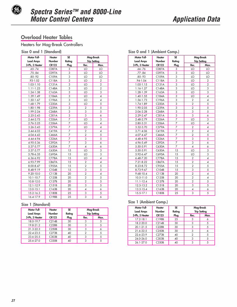
Overload Heater TablesHeaters for Mag-Break ControllersThe Mag-Break protector is factory adjusted to the minimum tripsetting.
WARNING: To maintain overload, short circuit, and groundfault protection, use the following instructions to selectheaters and to adjust the Mag-Break trip setting.
For continuous rated motors with a service factor of 1.15 to1.25, select heaters from the heater table. For continuous ratedmotors with a service factor of 1.0, multiply motor full-load cur-rent by 0.9 and use this value to select heaters.
Use the heater table to verify that the Mag-Break and currentlimiter rating is correct for the motor full-load current. Then setthe Mag-Break trip setting to the recommended value.If the Mag-Break trips when starting the motor, increase trip set-ting one step at a time until the motor can be consistently started.
Do not exceed the maximum trip setting shown in the heatertable.
Overload relay tripping current in 40°C ambient is the mini-mum value of heater full-load current multiplied by 1.25.
WARNING: Overload relays with automatic reset may auto-matically start a motor connected to a 2-wire control circuit.When automatic restarting is not desired, use a 3-wire con-trol circuit.
WARNING: Tripping of the Mag-Break may be an indicationthat a fault current has been interrupted. To provide continuedprotection against fire or shock hazard, all current-carryingparts and other components of the motor controller should beexamined and be replaced if damaged. If heater burnoutoccurs, the complete overload relay must be replaced.

Spectra Series™ and 8000-LineMotor Control Centers Application Data
J6
J
Size 2 (Standard )Motor Full- Heater TEC & Mag-BreakLoad Amps Number TECL Trip Setting
3-Ph, 3 Heater CR 123 Rating Rec. Max.8.81-9.27 C104B 15 2 59.28-9.99 C113B 15 2 610.0-11.1 C125B 15 3 611.2-12.1 C137B 15 3 711.2-12.1 C137B 30 LO 212.2-13.0 C151B 15 4 812.2-13.0 C151B 30 LO 213.1-15.5 C163B 30 1 315.6-16.8 C180B 30 1 416.9-18.0 C198B 30 2 518.1-19.7 C214B 30 2 519.8-21.6 C228B 30 2 621.7-23.9 C250B 30 3 721.7-23.9 C250B 50 LO 224.0-25.5 C273B 30 3 824.0-25.5 C273B 50 LO 325.6-26.0 C303B 30 3 925.6-28.2 C303B 50 LO 328.3-31.6 C330B 50 1 431.7-34.7 C366B 50 2 534.8-37.8 C400B 50 2 637.9-40.6 C440B 50 3 740.7-43.4 C460B 50 3 8
Motor Full- Heater TEC & Mag-BreakLoad Amps Number TECL Trip Setting
3-Ph, 3 Heater CR 123 Rating Rec. Max.28.8-32.0 F357B 50 1 432.1-34.2 F395B 50 2 534.3-36.7 F430B 50 2 636.8-43.4 F487B 50 3 743.5-43.9 F487B 100 1 344.0-46.6 F567B 100 1 346.7-52.6 F614B 100 1 352.7-55.6 F658B 100 1 455.7-58.7 F719B 100 2 558.8-67.1 F772B 100 2 567.2-70.6 F848B 100 3 670.7-76.3 F914B 100 3 770.7-76.3 F914B 150 LO 176.4-86.9 F104C 100 4 876.4-88.7 F104C 150 LO 288.8-93.4 F114C 150 1 393.5-102 F118C 150 1 3103-110 F133C 150 1 4111-122 F149C 150 1 4123-131 F161C 150 2 5
Size 2 (Ambient Comp.)
Size 3 (Standard and Ambient Comp.)
Size 3 (Standard and Ambient Comp.) cont.
Size 4 (Standard)
Motor Full- Heater TEC & Mag-BreakLoad Amps Number TECL Trip Setting
3-Ph, 3 Heater CR 123 Rating Rec. Max.28.8-32.0 F357B 50 2 432.1-34.2 F395B 50 2 534.3-36.7 F430B 50 2 636.8-43.4 F487B 50 3 736.8-43.8 F487B 100 LO 243.9-46.6 F567B 100 2 346.7-52.6 F614B 100 1 352.7-55.6 F658B 100 1 455.7-58.7 F719B 100 2 558.8-67.1 F772B 100 2 567.2-70.6 F848B 100 3 670.7-76.3 F914B 100 3 776.4-86.9 F104C 100 4 876.4-88.7 F104C 150 LO 288.8-93.4 F114C 150 1 393.5-105 F118C 150 1 3106-114 F133C 150 1 4115-128 F149C 150 2 5129-130 F161C 150 2 6
Size 4 (Ambient Comp.)
Size 5 (Standard and Ambient Comp.)
Motor Full- Heater TEC & Mag-BreakLoad Amps Number TECL Trip Setting
3-Ph, 3 Heater CR 123 Rating Rec. Max.9.04-9.61 C104B 15 2 59.62-10.5 C113B 15 2 610.6-11.6 C125B 15 3 711.7-12.5 C137B 15 3 811.7-12.5 C137B 30 LO 212.6-13.0 C151B 15 4 912.6-13.6 C151B 30 LO 313.7-16.7 C163B 30 1 316.8-17.9 C180B 30 1 518.0-18.7 C198B 30 2 518.8-20.4 C214B 30 2 620.5-22.7 C228B 30 2 722.8-24.7 C250B 30 3 822.8-24.7 C250B 50 LO 224.8-26.0 C273B 30 4 924.8-26.3 C273B 50 LO 426.4-29.5 C303B 50 LO 429.6-32.5 C330B 50 1 432.6-36.7 C366B 50 2 636.8-41.9 C400B 50 2 742.0-43.2 C440B 50 3 943.3-43.4 C460B 50 3 9
Motor Full- Heater TEC & Mag-BreakLoad Amps Number TECL Trip Setting
3-Ph, 3 Heater CR 123 Rating Rec. Max.17.8-18.4 F233B 30 1 518.5-21.1 F243B 30 1 621.2-22.1 F270B 30 2 722.2-26.0 F300B 30 3 726.1-28.0 F327B 50 LO 428.1-31.3 F357B 50 LO 431.4-33.3 F395B 50 1 533.4-34.3 F430B 50 1 634.4-40.9 F487B 50 1 641.0-43.4 F567B 50 2 843.5-44.7 F567B 100 LO 344.8-51.0 F614B 100 LO 351.1-52.0 F658B 100 1 452.1-55.4 F719B 100 1 4
Motor Full- Heater TEC & Mag-BreakLoad Amps Number TECL Trip Setting
3-Ph, 3 Heater CR 123 Rating Rec. Max.55.5-63.3 F772B 100 1 563.4-66.1 F848B 100 2 666.2-73.5 F914B 100 2 673.6-82.2 F104C 100 2 782.3-86.9 F114C 100 3 9
Overload Heater TablesHeaters for Mag-Break Controllers
Motor Full- Heater TEC & Mag-BreakLoad Amps Number TECL Trip Setting
3-Ph, 3 Heater CR 123 Rating Rec. Max.106-115 C592A 550-1670 2 6116-125 C630A 550-1670 3 7126-135 C695A 550-1670 3 7126-135 C695A 1000-3300 LO 3136-151 C778A 1000-3300 LO 3152-164 C867A 1000-3300 LO 4165-179 C955A 1000-3300 1 5180-195 C104B 1000-3300 2 5196-215 C113B 1000-3300 2 6216-231 C125B 1000-3300 3 6232-255 C137B 1000-3300 4 7256-270 C151B 1000-3300 4 HI
Spectra Series™ and 8000-LineMotor Control Centers Application Data
J7
Overload Heater TablesHeaters for Mag-Break Controllers
Size 0 and 1 (Standard)Motor Full- Heater SE Mag-BreakLoad Amps Number Rating Trip Setting
3-Ph, 3 Heater CR123 Plug Rec. Max..65-.74 C087A 3 LO LO.75-.84 C097A 3 LO LO.85-.92 C109A 3 LO LO.93-1.02 C118A 3 LO 21.03-1.10 C131A 3 LO 21.11-1.23 C148A 3 LO 21.24-1.38 C163A 3 LO 31.39-1.49 C184A 3 LO 41.50-1.67 C196A 3 LO 41.68-1.79 C220A 3 LO 51.80-1.98 C239A 3 2 51.99-2.24 C268A 3 3 52.25-2.43 C301A 3 3 62.44-2.75 C326A 7 LO 32.76-3.25 C356A 7 LO 43.26-3.43 C379A 7 LO 43.44-4.03 C419A 7 2 44.04-4.43 C466A 7 2 54.44-4.94 C526A 7 3 54.95-5.36 C592A 7 3 65.37-5.77 C630A 7 4 65.37-5.77 C630A 15 LO 35.78-6.35 C695A 15 LO 36.36-6.92 C778A 15 LO 46.93-7.99 C867A 15 2 48.00-8.47 C955A 15 2 58.48-9.19 C104B 15 3 59.20-10.0 C113B 20 2 410.1-10.7 C125B 20 2 510.8-12.0 C137B 20 2 512.1-12.9 C151B 20 3 513.0-15.1 C163B 20 4 615.2-16.3 C180B 25 3 516.4-17.9 C198B 25 3 6
Size 0 and 1 (Ambient Comp.)Motor Full- Heater SE Mag-BreakLoad Amps Number Rating Trip Setting
3-Ph, 3 Heater CR123 Plug Rec. Max..66-.76 C087A 3 LO LO.77-.84 C097A 3 LO LO.85-.93 C109A 3 LO LO.94-1.04 C118A 3 LO 21.05-1.15 C131A 3 LO 21.16-1.27 C148A 3 LO 31.28-1.39 C163A 3 LO 31.40-1.55 C184A 3 LO 41.56-1.73 C196A 3 2 41.74-1.89 C220A 3 2 51.90-2.05 C239A 3 2 52.06-2.28 C268A 3 3 52.29-2.47 C301A 3 3 62.48-2.79 C326A 7 LO 32.80-3.31 C356A 7 LO 43.32-3.70 C379A 7 2 43.71-4.06 C419A 7 2 44.07-4.47 C466A 7 2 54.48-4.95 C526A 7 3 54.96-5.49 C592A 7 3 65.50-5.91 C630A 7 4 65.50-5.91 C630A 15 LO 35.92-6.47 C695A 15 LO 36.48-7.20 C778A 15 2 47.21-8.22 C867A 15 2 48.23-8.72 C955A 15 2 58.73-9.67 C104B 15 3 59.68-10.4 C113B 20 2 410.5-11.0 C125B 20 2 411.1-12.4 C137B 20 2 512.5-13.2 C151B 20 3 513.3-15.4 C163B 20 4 615.5-17.1 C180B 25 3 5
Size 1 (Standard)Motor Full- Heater SE Mag-BreakLoad Amps Number Rating Trip Setting
3-Ph, 3 Heater CR123 Plug Rec. Max.18.0-19.7 C214B 30 3 519.8-21.2 C228B 30 3 521.3-22.3 C250B 30 3 622.4-23.5 C273B 40 2 523.6-25.5 C303B 40 3 525.6-27.0 C330B 40 3 5
Size 1 (Ambient Comp.)Motor Full- Heater SE Mag-BreakLoad Amps Number Rating Trip Setting
3-Ph, 3 Heater CR123 Plug Rec. Max.17.2-18.1 C198B 25 3 618.2-20.0 C214B 30 3 520.1-21.5 C228B 30 3 521.6-22.5 C250B 30 3 622.6-23.9 C273B 40 2 524.0-26.0 C303B 40 3 526.1-27.0 C330B 40 3 5

Spectra Series™ and 8000-LineMotor Control Centers Application Data
J8
J
Overload Heater TablesHeaters for Mag-Break Controllers
Size 2 (Standard)Motor Full- Heater SE Mag-BreakLoad Amps Number Rating Trip Setting
3-Ph, 3 Heater CR123 Plug Rec. Max.8.81-9.27 C104B 15 3 59.28-9.99 C113B 20 2 410.0-11.1 C125B 20 2 511.2-12.1 C137B 20 3 512.2-13.0 C151B 20 3 513.1-15.5 C163B 20 4 615.6-16.8 C180B 25 3 516.9-18.0 C198B 25 3 618.1-19.7 C214B 30 3 519.8-21.6 C228B 30 3 521.7-23.9 C250B 40 2 524.0-25.5 C273B 40 2 525.6-28.2 C303B 50 2 528.3-31.6 C330B 50 3 531.7-34.7 C366B 50 3 634.8-37.8 C400B 50 3 637.9-40.6 C440B 60 3 540.7-43.4 C460B 60 3 6
Size 2 (Ambient Comp.)Motor Full- Heater SE Mag-BreakLoad Amps Number Rating Trip Setting
3-Ph, 3 Heater CR123 Plug Rec. Max.9.04-9.61 C104B 15 3 59.62-10.5 C113B 20 3 410.6-11.6 C125B 20 2 511.7-12.5 C137B 20 3 512.6-13.6 C151B 20 3 513.7-16.7 C163B 20 4 616.8-17.9 C180B 25 3 518.0-18.7 C198B 25 3 618.8-20.4 C214B 30 3 520.5-22.7 C228B 30 3 622.8-24.7 C250B 40 2 524.8-26.3 C273B 40 2 526.4-29.5 C303B 50 2 529.6-32.5 C330B 50 3 532.6-36.7 C366B 50 3 636.8-41.9 C400B 50 3 642.0-43.2 C440B 60 3 543.3-43.4 C460B 60 3 6
Size 3 (Standard and Ambient Comp.) cont.
Size 3 (Standard and Ambient Comp.)Motor Full- Heater SE Mag-BreakLoad Amps Number Rating Trip Setting
3-Ph, 3 Heater CR123 Plug Rec. Max.17.8-18.4 F233B 30 2 518.5-21.1 F243B 30 3 521.2-22.1 F207B 30 3 522.2-26.0 F300B 40 3 526.1-28.0 F327B 40 3 528.1-31.3 F357B 50 3 531.4-33.3 F395B 50 3 533.4-34.3 F430B 50 3 534.4-40.9 F487B 70 2 541.0-44.7 F567B 70 3 544.8-51.0 F614B 100 LO 4
Motor Full- Heater SE Mag-BreakLoad Amps Number Rating Trip Setting
3-Ph, 3 Heater CR123 Plug Rec. Max.51.1-52.0 F658B 100 LO 452.1-55.4 F719B 100 2 555.5-63.3 F772B 100 3 563.4-66.1 F848B 100 3 566.2-73.5 F914B 100 3 673.6-82.2 F104C 150 2 482.3-86.9 F114C 150 2 5
Size 4 (Standard)Motor Full- Heater SE Mag-BreakLoad Amps Number Rating Trip Setting
3-Ph, 3 Heater CR123 Plug Rec. Max.28.8-32.0 F357B 50 3 532.1-34.2 F395B 50 3 534.3-36.7 F430B 70 2 536.8-43.9 F487B 70 3 544.0-46.6 F567B 70 3 546.7-52.6 F614B 100 2 452.7-55.6 F658B 100 2 555.7-58.7 F719B 100 2 558.8-67.1 F772B 100 3 567.2-70.6 F848B 100 3 670.7-76.3 F914B 150 2 476.4-88.7 F104C 150 2 588.8-93.4 F114C 150 3 593.5-102.0 F118C 150 3 5103.0-110.0 F133C 150 3 5111.0-122.0 F149C 150 4 6123.0-131.0 F161C 150 4 6
Size 4 (Ambient Comp.)Motor Full- Heater SE Mag-BreakLoad Amps Number Rating Trip Setting
3-Ph, 3 Heater CR123 Plug Rec. Max.28.8-32.0 F357B 50 3 532.1-34.2 F395B 50 3 534.3-36.7 F430B 70 2 536.8-43.8 F487B 70 3 543.9-46.6 F567B 70 3 546.7-52.6 F614B 100 2 452.7-55.6 F658B 100 2 555.7-58.7 F719B 100 2 558.8-67.1 F772B 100 3 567.2-70.6 F848B 100 3 670.7-76.3 F914B 150 2 476.4-88.7 F104C 150 2 588.8-93.4 F114C 150 3 593.5-105.0 F118C 150 3 5106.0-114.0 F133C 150 3 5115.0-128.0 F149C 150 4 6129.0-130.0 F161C 150 4 6

Spectra Series™ and 8000-LineMotor Control Centers Application Data
J9
Overload Heater TablesHeaters for Mag-Break Controllers
Size 4 (Standard)Motor Full- Heater SF Mag-BreakLoad Amps Number Rating Trip Setting
3-Ph, 3 Heater CR123 Plug Rec. Max.28.8-32.0 F357B 70 2 432.1-34.2 F395B 70 2 434.3-36.7 F430B 70 2 536.8-43.9 F487B 70 2 544.0-46.6 F567B 70 3 546.7-52.6 F614B 100 2 452.7-55.6 F658B 100 2 455.7-58.7 F719B 100 2 558.8-67.1 F772B 150 LO 467.2-70.6 F848B 150 LO 470.7-76.3 F914B 150 2 476.4-88.7 F104C 200 LO 488.8-93.4 F114C 200 LO 493.5-102.0 F118C 200 LO 5103.0-110.0 F133C 200 2 6111.0-122.0 F149C 200 2 6123.0-131.0 F161C 200 2 6
Size 4 (Ambient Comp.)Motor Full- Heater SF Mag-BreakLoad Amps Number Rating Trip Setting
3-Ph, 3 Heater CR123 Plug Rec. Max.28.8-32.0 F357B 70 2 432.1-34.2 F395B 70 3 434.3-36.7 F430B 70 3 536.8-43.8 F487B 70 3 543.9-46.6 F567B 70 3 546.7-52.6 F614B 100 2 452.7-55.6 F658B 100 2 455.7-58.7 F719B 100 2 558.8-67.1 F772B 150 LO 467.2-70.6 F848B 150 LO 470.7-76.3 F914B 150 2 476.4-88.7 F104C 200 LO 488.8-93.4 F114C 200 LO 493.5-105.0 F118C 200 LO 5106.0-114.0 F133C 200 2 6115.0-128.0 F149C 200 2 6129.0-130.0 F161C 200 2 6
Size 5 – 300:15 CT (Standard and Ambient Comp.)
Size 6 – 600:5 CT (Standard and Ambient Comp.)
Size 6 – 600:5 CT (Standard and Ambient Comp.)Motor Full- Heater SG InstantaneousLoad Amps Number Rating Trip Setting
3-Ph, 3 Heater CR123 Plug Rec. Max.181-197 C220A 400 MIN. 4198-214 C239A 400 2 5215-238 C268A 500 MIN 4239-258 C301A 500 MIN 4259-290 C326A 500 2 5291-346 C356A 600 MIN 5347-387 C379A 600 2 5388-424 C419A 600 3 MAX
Motor Full- Heater SK InstantaneousLoad Amps Number Rating Trip Setting
3-Ph, 3 Heater CR123 Plug Rec. Max.181-197 C220A 400 LO 4198-214 C239A 400 2 4215-238 C268A 400 3 5239-258 C301A 500 LO 4259-290 C326A 500 2 5291-346 C356A 800 LO 4347-387 C379A 800 LO 5388-423 C419A 800 2 5424-467 C466A 1000 LO 4468-516 C526A 1000 2 4517-540 C592A 1000 2 5
Motor Full- Heater SG InstantaneousLoad Amps Number Rating Trip Setting
3-Ph, 3 Heater CR123 Plug Rec. Max.106-115 C592A 250 LO 3116-125 C630A 250 LO 4126-135 C695A 250 2 4136-151 C778A 250 2 5152-164 C867A 300 2 4165-179 C955A 300 2 5180-195 C104B 350 2 4196-215 C113B 350 2 5216-231 C125B 400 2 4232-255 C137B 400 2 5256-270 C151B 400 3 5

Spectra Series™ and 8000-LineMotor Control Centers Application Data
J10
J
Overload Relays for Compact 6” Starter CL45A310MJ, NEMA Size 1
Overload Heater TablesOverload Relays
Electronic Overloads for Circuit Breaker Controllers Tripping current is 120% of Dial setting. Motors with 1.15-1.25 service factor, set dial to motor FLA Motors with 1.0 service factor,set dial to 0.9 motor FLA.
NEMA Size FLA Range in Amps Catalog Number Breaker Frame & Type1 0.8 to 1.59 CR324CXD E Mag. & Thermal Mag.1 1.6 to 3.19 CR324CXE E Mag. & Thermal Mag.1 3.2 to 6.49 CR324CXF E Mag. & Thermal Mag.1 6.5 to 12.8 CR324CXG E Mag. & Thermal Mag.1 13 to 27 CR324CXH E Mag. & Thermal Mag.2 13 to 25.6 CR324DXG E Mag. & Thermal Mag.2 26 to 49.9 CR324DXH E Mag. & Thermal Mag.2 50 to 100 CR324DXJ E Mag. & Thermal Mag.3 17 to 34.9 CR324FXK E Mag. & Thermal Mag.3 35 to 64.9 CR324FXL E Mag. & Thermal Mag.3 65 to 90 CR324FXM E Mag. & Thermal Mag.4 17 to 34.9 CR324FXK E,F&G Mag. & Thermal Mag.4 35 to 64.9 CR324FXL E,F&G Mag. & Thermal Mag.4 65 to 135 CR324FXM E,F&G Mag. & Thermal Mag.
5 ➀ 32 to 64.0 CR324GXN G Mag. & Thermal Mag.5 ➀ 65 to 129.9 CR324GXP G Mag. & Thermal Mag.5 ➀ 130 to 270 CR324GXQ G Mag. & Thermal Mag.6 ➁ 130 to 259.9 CR324HXS G,K Mag. & Thermal Mag.6 ➁ 260 to 540 CR324HXT K Mag. & Thermal Mag
FLA Range in AmpsClass 10 Class 20
Catalog Number Catalog NumberBreaker Frame & Type
0.4-.65 RTN1D E Mag. & Thermal Mag.0.65-1.1 RTN1F E Mag. & Thermal Mag.
1-1.5 RTN1G E Mag. & Thermal Mag.1.3-1.9 RTN1H E Mag. & Thermal Mag.1.8-2.7 RTN1J E Mag. & Thermal Mag.2.5-4.1 RTNIK RT12K E Mag. & Thermal Mag.4.0-6.3 RTNIL RT12L E Mag. & Thermal Mag.5.5-8.5 RTNIM RT12M E Mag. & Thermal Mag.8.0-12 RTNIN RT12N E Mag. & Thermal Mag.10.0-16 RTNIP RT12P E Mag. & Thermal Mag.14.5-18 RTNIS RT12S E Mag. & Thermal Mag.17.5-22 RTNIT RT12T E Mag. & Thermal Mag.21-26 RTNIU RT12U E Mag. & Thermal Mag.
➀ 300:15 CT’s➁ 800:5 CT’s
Spectra Series™ and 8000-LineMotor Control Centers Application Data
J11
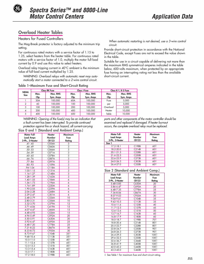
Overload Heater TablesHeaters for Fused ControllersThe Mag-Break protector is factory adjusted to the minimum tripsetting.For continuous rated motors with a service factor of 1.15 to1.25, select heaters from the heater table. For continuous ratedmotors with a service factor of 1.0, multiply the motor full-loadcurrent by 0.9 and use this value to select heaters.Overload relay tripping current in 40°C ambient is the minimumvalue of full-load current multiplied by 1.25.
WARNING: Overload relays with automatic reset may auto-matically start a motor connected to a 2-wire control circuit.
When automatic restarting is not desired, use a 3-wire controlcircuit.
Provide short-circuit protection in accordance with the NationalElectrical Code, except Fuses are not to exceed the value shownin the table.Suitable for use in a circuit capable of delivering not more thanthe maximum RMS symmetrical amperes indicated in the tablebelow, 600-volts maximum, when protected by an appropriatefuse having an interrupting rating not less than the availableshort-circuit current.
Table 1–Maximum Fuse and Short-Circuit RatingClass RK Fuse Class J Fuse Class K-1, K-5 Fuse
NEMAMax. Max. RMS Max. Max. RMS Max. Max. RMSSizeClip Sym. Amps Clip Sym. Amps Clip Sym. Amps
1 30A 100,000 60A 100,000 Fuse 5,0002 60 100,000 100 100,000 per 5,0003 100 100,000 200 100,000 Overload 5,0004 200 100,000 400 100,000 Heater 10,0005 400 100,000 600 100,000 Table 10,000
WARNING: Opening of the fuse(s) may be an indication thata fault current has been interrupted. To provide continuedprotection against fire or shock hazard, all current-carrying
parts and other components of the motor controller should beexamined and replaced if damaged. If heater burnoutoccurs, the complete overload relay must be replaced.
Size 0 and 1 (Standard and Ambient Comp.)
Size 2 (Standard and Ambient Comp.)
Motor Full- Heater MaximumLoad Amps Number Fuse
3-Ph., 3-Heater CR123 Rating.41-.45 C054A 3.46-.49 C060A 3.50-.53 C066A 3.54-.59 C071A 3.60-.65 C078A 3.66-.76 C087A 3.77-.84 C097A 3.85-.93 C109A 3.94-1.04 C118A 31.05-1.15 C131A 31.16-1.27 C148A 31.28-1.39 C163A 31.40-1.55 C184A 61.56-1.73 C196A 61.74-1.89 C220A 61.90-2.05 C239A 62.06-2.28 C268A 62.29-2.47 C301A 62.48-2.79 C326A 102.80-3.31 C356A 103.32-3.70 C379A 123.71-4.06 C419A 154.07-4.47 C466A 154.48-4.95 C526A 154.96-5.49 C592A 205.50-5.91 C630A 205.92-6.47 C695A 256.48-7.20 C778A 257.21-8.22 C867A 308.23-8.72 C955A 308.73-9.67 C104B 35➀
9.68-10.4 C113B 35➀
10.5-11.0 C125B 40➀
11.1-12.4 C137B 45➀
12.5-13.2 C151B 50➀
13.3-15.4 C163B 60➀
15.5-17.1 C180B 60➀
17.2-18.0 C198B 60➀
Motor Full- Heater MaximumLoad Amps Number Fuse
3-Ph., 3-Heater CR123 RatingSize 1
17.2-18.1 C198B 60➀
18.2-20.0 C214B 60➀
20.1-21.5 C228B 60➀
21.6-22.5 C250B 60➀
22.6-23.9 C273B 60➀
24.0-26.3 C303B 60➀
26.4-27.0 C330B 60➀
➀ See Table 1 for maximum fuse and short-circuit rating.
Motor Full- Heater MaximumLoad Amps Number Fuse
3-Ph., 3-Heater CR123 Rating5.48-5.85 C630A 205.86-6.47 C695A 206.48-7.35 C778A 257.36-8.06 C867A 308.07-9.03 C955A 309.04-9.61 C104B 359.62-10.5 C113B 3510.6-11.6 C125B 4011.7-12.5 C137B 4512.6-13.6 C151B 5013.7-16.7 C163B 6016.8-17.9 C180B 6018.0-18.7 C198B 70➀
18.8-20.4 C214B 80➀
20.5-22.7 C228B 80➀
22.8-24.7 C250B 90➀
24.8-26.3 C273B 90➀
26.4-29.5 C303B 100➀
29.6-32.5 C330B 100➀
32.6-36.7 C366B 100➀
36.8-41.9 C400B 100➀
42.0-43.2 C440B 100➀
43.3-45.0 C460B 100➀

J
Spectra Series™ and 8000-LineMotor Control Centers Application Data
J12
Overload Heater TablesHeaters for Fused Controllers
Motor Full- Heater MaximumLoad Amps Number Fuse
3-Ph., 3-Heater CR123 Rating19.0-19.3 F233B 7019.4-22.1 F243B 8022.2-23.4 F270B 8023.5-27.0 F300B 9027.1-29.1 F327B 10029.2-31.8 F357B 110➀
31.9-33.9 F395B 125➀
34.0-37.6 F430B 125➀
37.7-41.9 F487B 150➀
42.0-47.7 F567B 175➀
47.8-52.1 F614B 175➀
52.2-55.8 F658B 200➀
55.9-59.7 F719B 200➀
59.8-68.1 F772B 200➀
68.2-71.5 F848B 200➀
71.6-78.2 F914B 200➀
78.3-87.5 F104C 200➀
87.6-90.0 F114C 200➀
Size 3 (Standard) Size 4 (Ambient Comp.)Motor Full- Heater MaximumLoad Amps Number Fuse
3-Ph., 3-Heater CR123 Rating28.8-32.0 F357B 11032.1-34.2 F395B 12534.3-36.7 F430B 12536.8-43.9 F487B 15044.0-46.6 F567B 17546.7-52.6 F614B 17552.7-55.6 F658B 20055.7-58.7 F719B 225➀
58.8-67.1 F772B 225➀
67.2-70.6 F848B 250➀
70.7-76.3 F914B 275➀
76.4-88.7 F104C 300➀
88.8-93.4 F114C 350➀
93.5-105 F118C 350➀
106-114 F133C 400➀
115-128 F149C 400➀
129-131 F161C 400➀
132-135 F174C 400➀
Size 5 – 300:15CT (Standard and Ambient Comp.)Motor Full- Heater MaximumLoad Amps Number Fuse
3-Ph., 3-Heater CR123 Rating109-118 C592A 600119-128 C630A 600129-138 C695A 600139-155 C778A 600156-168 C867A 600169-184 C955A 600185-200 C104B 600201-221 C113B 600222-237 C125B 600238-262 C137B 600263-270 C151B 600
Size 3 (Ambient Comp.)Motor Full- Heater MaximumLoad Amps Number Fuse
3-Ph., 3-Heater CR123 Rating17.8-18.4 F233B 7018.5-21.1 F243B 8021.2-22.1 F270B 8022.2-26.1 F300B 9026.2-28.0 F327B 10028.1-31.3 F357B 110➀
31.4-33.3 F395B 125➀
33.4-34.3 F430B 125➀
34.4-40.9 F487B 150➀
41.0-44.7 F567B 150➀
44.8-51.0 F614B 175➀
51.1-52.0 F658B 200➀
52.1-55.4 F719B 200➀
55.5-63.3 F772B 200➀
63.4-66.1 F848B 200➀
66.2-73.5 F914B 200➀
73.6-82.2 F104C 200➀
82.3-90.0 F114C 200➀
Size 4 (Standard)Motor Full- Heater MaximumLoad Amps Number Fuse
3-Ph., 3-Heater CR123 Rating27.1-32.2 F357B 11032.3-34.0 F395B 12534.1-36.8 F430B 12536.9-44.6 F487B 15044.7-48.4 F567B 17548.5-53.9 F614B 17554.0-57.4 F658B 20057.5-60.0 F719B 225➀
60.1-69.5 F772B 225➀
69.6-71.7 F848B 250➀
71.8-79.9 F914B 275➀
80.0-92.3 F104C 300➀
92.4-97.0 F114C 350➀
97.1-108 F118C 400➀
109-118 F133C 400➀
119-131 F149C 400➀
132-135 F161C 400➀
➀ See Table 1 (page J-17) for maximum fuse and short-circuit rating.
Electronic Overload Table for Fusible Controllers Tripping current is 120% of Dial setting. Motors with 1.15-1.25service factor, set dial to motor FLA Motors with 1.0 service factor,set dial to 0.9 motor FLA.
➀ 300:15 CT’s➁ 800:5 CT’s
NEMA Size FLA Range in Amps Catalog Number Max. Fuse in Amps1 0.8 to 1.59 CR324CXD Class R 30 Class J 601 1.6 to 3.19 CR324CXE1 3.2 to 6.49 CR324CXF1 6.5 to 12.8 CR324CXG1 13 to 27 CR324CXH2 13 to 25.6 CR324DXG 60 1002 26 to 49.9 CR324DXH2 50 to 100 CR324DXJ3 17 to 34.9 CR324FXK 100 2003 35 to 64.9 CR324FXL3 65 to 90 CR324FXM4 17 to 34.9 CR324FXK 200 4004 35 to 64.9 CR324FXL4 65 to 135 CR324FXM
5 ➀ 32 to 64.0 CR324GXN 400 6005 ➀ 65 to 129.9 CR324GXP5 ➀ 130 to 270 CR324GXQ6 ➁ 130 to 259.9 CR324HXS 600 Class L 12006 ➁ 260 to 540 CR324HXT

Spectra Series™ and 8000-LineMotor Control Centers Application Data
J13
200 and 208 VoltsUL Class J Time-Delay RK-5
Typical Switch Time Delay No Time DelayBMC CSCSize Hp FLA Amp CSC# AJT Clip CSC# A4J Clip FRN Clip TR Clip
1⁄2 2.3 30 3 30 10 30 2.8 30 3.5 303⁄4 3.2 30 5 30 10 30 4 30 4.5 301 3.9 30 6 30 15 30 5 30 6.25 30
11⁄2 5.3 30 8 30 20 30 7 30 8 301 2 7.1 30 10 30 25 30 9 30 12 30
3 10.6 30 15 30 30 30 12 30 15 305 16.3 30 25 30 45 60 20 30 25 30
71⁄2 25.3 30 30 30 60 60 30 30 30 302 10 31.3 60 50 60 90 100 40 60 40 60
15 45.1 100 60 60 110 200 60 60 60 603 20 591 100 90 100 150 200 70 100 90 100
25 731 100 100 100 175 200 90 100 100 10030 881 200 125 200 200 200 100 100 125 200
440 120 200 175 200 225 400 150 200 175 20050 150 400 225 400 300 400 175 200 225 400
5 60 174 400 250 400 350 400 200 200 225 40075 210 400 300 400 450 600 250 400 300 400
UL Class J Time-Delay RK-5Typical Switch Time Delay No Time Delay BMC CSC
Size Hp FLA Amp CSC# AJT Clip CSC# A4J Clip FRN Clip TR Clip1⁄2 2.0 30 3 30 10 30 2.5 30 3 303⁄4 2.8 30 4 30 15 30 3.5 30 4 301 3.4 30 6 30 15 30 4 30 5.6 30
11⁄2 4.6 30 8 30 30 30 6.25 30 8 301 2 6.2 30 10 30 25 30 8 30 10 30
3 9.2 30 15 30 30 30 12 30 15 305 14.2 30 25 30 45 60 17.5 30 25 30
71⁄2 22.0 30 30 30 60 60 25 30 30 3010 27.2 60 40 60 90 100 35 60 40 60
2 15 39.2 60 60 60 – – 50 60 60 6015 39.2 100 60 60 110 200 – – – –20 51.4 100 80 100 150 200 60 60 80 100
3 25 63.6 100 100 100 175 200 80 100 100 10030 76.6 100 100 100 200 200 100 100 100 10040 104 200 150 200 225 400 125 200 150 200
4 50 130 200 200 200 300 400 150 200 200 20060 151 400 225 400 350 400 175 200 225 400
5 75 183 400 300 400 400 400 225 400 300 400100 240 400 350 400 600 600 300 400 350 400125 296 600 450 600 600 600 350 400 450 600
6 150 348 600 500 600 – – 450 600 500 600200 468 600 – – – – 500 600 600 600
230 Volts
BMC–Bussman FuseCSC–Chase Shawmut Fuse
Starter Fuse SelectionThe following tables are furnished as a guide. Check vendor fusecharacteristics before making final selection.

Spectra Series™ and 8000-LineMotor Control Centers Application Data
J14
J
UL Class J Time-Delay K-5Typical Switch Time Delay No Time Delay BMC CSC
Size Hp FLA Amp CSC# AJT CLIP CSC# A4J CLIP FRS Clip TRS Clip1⁄2 1.0 30 1.5 30 3 30 1.25 30 1.4 303⁄4 1.4 30 2 30 3 30 1.6 30 2 301 1.7 30 3 30 6 30 2 30 2.5 30
11⁄2 2.3 30 4 30 6 30 2.8 30 4 301 2 3.1 30 5 30 10 30 3.5 30 5 30
3 4.6 30 8 30 15 30 5 30 7 305 7.1 30 10 30 25 30 9 30 10 30
71⁄2 11.0 30 15 30 35 60 15 30 15 3010 13.6 30 20 30 40 60 17.5 30 20 3015 19.6 60 30 30 50 60 25 30 30 30
2 20 25.7 60 40 60 90 100 35 60 40 6025 31.8 60 50 60 100 100 40 60 50 6030 38.3 100 60 60 110 200 45 60 60 60
3 40 52.0 100 80 100 125 200 60 60 75 10050 65.0 100 100 100 150 200 80 100 100 10060 75.5 200 110 200 175 200 90 100 110 200
4 75 91.5 200 150 200 225 400 110 200 150 200100 120 200 175 200 225 400 150 200 175 200125 148 400 225 400 300 400 200 200 225 400
5 150 172 400 250 400 350 400 225 400 250 400200 224 400 300 400 500 600 300 400 350 400250 295 600 450 600 600 600 350 400 400 400
6 300 343 600 500 600 – – 400 400 500 600350 396 600 600 600 – – 450 600 600 600400 453 600 – – – – 500 600 600 600
Starter Fuse Selection
460 Volts
UL Class J Time-Delay K-5Typical Switch Time Delay No Time Delay BMC CSC
Size Hp FLA Amp CSC# AJT CLIP CSC# A4J CLIP FRS Clip TRS Clip1⁄2 .8 30 1.5 30 3 30 1.25 30 1.4 303⁄4 1.1 30 2 30 3 30 1.25 30 1.6 301 1.4 30 2 30 6 30 1.6 30 2 30
11⁄2 1.8 30 3 30 6 30 2.25 30 3 301 2 2.5 30 4 30 10 30 2.8 30 4 30
3 3.7 30 6 30 15 30 4.5 30 6 305 5.7 30 10 30 20 30 7 30 9 30
71⁄2 8.8 30 15 30 30 30 10 30 15 3010 10.9 30 15 30 35 60 15 30 15 3015 15.7 60 25 30 45 60 20 30 25 30
2 20 20.6 60 35 60 60 60 25 30 35 6025 25.4 60 40 60 80 100 35 60 40 6030 30.6 100 45 60 100 100 40 60 45 60
3 40 41.6 100 60 60 110 200 45 60 60 6050 52.0 100 80 100 125 200 60 60 80 10060 60.4 200 90 100 150 200 70 100 90 100
4 75 73.2 200 125 200 175 200 90 100 125 200100 96.0 200 150 200 225 400 110 200 150 200125 118 400 175 200 225 400 150 200 175 200
5 150 138 400 225 400 300 400 175 200 225 400200 179 400 300 400 400 400 225 400 300 400250 236 600 350 400 500 600 300 400 350 400
6300 274 600 450 600 600 600 350 400 450 600350 317 600 500 600 – – 400 400 500 600400 363 600 600 600 – – 450 600 600 600
575 Volts

Spectra Series™ and 8000-LineMotor Control Centers Application Data
J15
Control Transformer Fusing Heat Loss ConsiderationsIn determining the heat loss of a motor control center for airconditioning requirements, 250 watts per foot of lineup is areasonable assumption.
Actual heat loss will vary due to section loading and diversityfactors. A typical motor control center may operate normally at60 percent of maximum possible loading.
Fully rated circuit breaker starters with CPT’s, approximate losses are:
Size 1– 27 Watts
Size 2– 57 Watts
Size 3–130 Watts
Size 4–200 Watts
Size 5–300 Watts
Size 6–650 Watts
Heat losses for feeders and mains vary depending on framesize, loading and type of trip with electronic trips having lower losses. The following table provides a general guide for estimat-ing losses assuming 80 percent loading. For critical applica-tions refer to the Company.
Typical losses for transformers:
1kVA, 1-Ph 75 Watts
5 kVA, 1-Ph 190 Watts
9 kVA, 3-Ph 295 Watts
15 kVA, 3-Ph 460 Watts
30 kVA, 3-Ph 1000 Watts
Horizontal and vertical bus losses, when loaded to capacity areapproximately 100 watts per section.
Solid State Starters or VFDs will typically generate 3 watts perampere of load during operation.
Typical CPT Ratings (480V/120V Shown)Open CircuitVA %R %X
Secondary Volts60 9.05 1.03 131.9100 6.39 1.18 129.4150 5.02 1.01 127.3200 5.09 1.06 126.2250 6.81 .88 127.8300 5.15 .73 126.4500 5.84 1.45 128.7
CPT Primary Fuse Amps Sec. Fuse AmpsVA 208V 240V 380V 480V 600V 120V 240V60 1 1 1 0.5 0.5 0.6 0.3100 2 2 1.25 1 1 1 0.5150 3 3 2 1.5 1.25 1.6 0.8200 4 4 2 2 1.5 2 1250 5 5 2 2 2 2.5 1.25300 6 6 3.5 2 2 3.2 1.6500 6 ➀ 6 5 4 5 2.5750 ➀ ➀ 8 7 6 7 3.51000 ➀ ➀ ➀ ➀ 8 10 5
Primary Fuses–Class CC Or Equivalent (GOULD #ATM-R STD)Secondary Fuses– Class H Or Equivalent (GOULD #TR STD)
➀ Requires class RK-5 time delay or equivalent.
Rating (Amps) Loss (Watts)50 15100 20150 25225 40400 50600 801200 150

Spectra Series™ and 8000-LineMotor Control Centers Application Data
J16
J
Non-Motor LoadsWhen selecting contactors for non-motor loads, the followingload characteristics should be considered:
1. Voltage and maximum continuous current.2. Maximum peak inrush current and duration.3. RMS current and duration of maximum current on cyclic
loads.4. Frequency of operation.5. Maximum interrupting current, voltage, power factor and
wave form.6. Available short-circuit current.
Non-motor load ratings are based on the use of two poles tocontrol single-phase loads and three poles to control three-phase loads.
Capacitor switching, requires special considerations. A dis-charged capacitor acts essentially like a short circuit, and theinrush current is limited by the impedance connected in series
with the capacitor which includes connecting cables. Therefore,the maximum capacitance which can be switched by a contac-tor will increase with higher series impedance. Switching morethan one capacitor or capacitor bank in close electrical proximi-ty to each other should be avoided as the energized capacitorbank can increase the inrush current to the second bank when itis energized. Reactors or resistors may be required between thetwo capacitor banks to limit inrush currents.
NEMA Standards require shunt capacitors to operate satisfacto-rily at 135 percent of rated KVAR due to manufacturing toler-ances and other variations. The higher inrush and steady statecurrents associated with these capacitors should be taken intoconsideration.
NEMA Publication ICS2-210 covers non-motor loads.
NEMA Contactor Ratings
➀ 300-volts maximum, Tungsten lamp loads include infrared lamps having Tungsten filaments.
➁ Resistive loads include electric discharge lamps such as fluorescent,mercury, vapor, etc.
Maximum Transformer Primary Switching (kVA)Cont. Inrush Tung Transformers having inrush currents of not more Transformers having inrush currents of over
Size ofAmps Current sten➀
Resistivethan 20 times FLA 20 through 40 times FLA
Contactor(Amps Lamps
Loads➀Single-Phase Volts Three-Phase Volts Single-Phase Volts Three-Phase Volts
Peak) 120 240 480 600 208 240 480 600 120 240 480 600 208 240 480 6000.6 1.2 2.4 3 1.8 2.1 4.2 5.2 0.3 0.6 1.2 1.5 0.9 1.0 2.1 2.61.2 2.4 4.9 6.2 3.6 4.3 8.5 11 0.6 1.2 2.5 3.1 1.8 2.1 4.3 5.32.1 4.1 8.3 10 6.3 7.2 14 18 1.0 2.1 4.2 5.2 3.1 3.6 7.2 8.94.1 8.1 16 20 12 14 28 35 2.0 4.1 8.1 10 6.1 7.0 14 186.8 14 27 34 20 23 47 59 3.4 6.8 14 17 10 12 23 2914 27 54 68 41 47 94 117 6.8 14 27 34 20 24 47 5927 54 108 135 81 94 188 234 14 27 54 68 41 47 94 117
0 18 140 10 181 27 288 15 272 45 483 30 453 90 947 60 904 135 1581 120 1355 270 3163 240 2706 540 6326 480 540
Motor Loads
Normal Starting Duty HP/KW rating by NEMA SizeDescription 1 2 3 4 5 6
Single Phase115V 2 3 7.5 – – –230V 3 7.5 15 – – –200V 7.5/5.5 10/7.5 25/18.5 40/30 75/55 150/110230V 7.5/5.5 15/11 30/22 50/37 100/75 200/150
Three Phase 380/415V 10/7.5 25/18.5 50/37 75/55 150/110 300/260460V 10/7.5 25/18.5 50/37 100/75 200/150 400/260575V 10/7.5 25/18.5 50/37 100/75 200/150 400/260
NEMA Contactor Ratings

Spectra Series™ and 8000-LineMotor Control Centers Application Data
J17
Non-Motor LoadsNEMA Contactor Ratings for Single Capacitor or Capacitor Bank Switching
NEMA Contactor for Heating Loads
Size ofContinuous Three-Phase Rating of Capacitor
ControllerRatings RMS Maximum Size of Three-Phase Capacitor in kVAR or Available Current➀ in Amperes RMS Sym.
Amperes 3000 5000 10,000 14,000 18,000 22,000At 230 Volts, 60 Hertz
2 45 12 8 4 3 2 23 90 27 27 15 11 9 74 135 40 40 40 30 24 205 270 80 80 80 80 80 756 540 160 160 160 160 160 160
At 460 Volts, 60 Hertz2 45 25 16 8 6 4 43 90 53 53 31 23 18 154 135 80 80 80 61 49 415 270 160 160 160 160 160 1496 540 320 320 320 320 320 320
At 575 Volts, 60 Hertz2 45 31 20 10 7 6 53 90 67 67 39 29 23 194 135 100 100 100 77 61 515 270 200 200 200 200 200 1896 540 400 400 400 400 400 400
➀ Available at capacitor terminals.➁ Applicable only to resistive loads having inrush currents not exceeding 1.5
times the continuous current rating.③ Spectra CB will permit deletion of overload heaters for these loads.
Continuous Maximum kW Ratings➁
NEMA Current 575 Volts 460 Volts 230 Volts 115 VoltsSize Rating 2-Pole 3-Pole 2-Pole 3-Pole 2-Pole 3-Pole 2-Pole 3-Pole
Amps 1-Ph 3-Ph 1-Ph 3-Ph 1-Ph 3-Ph 1-Ph 3-Ph00 9 5 9 4 7 2 3.5 1 1.750 18 10 18 8 14 4 7 2 3.51 27 15 25 12 20 6 10 3 52 45 25 43 20 34 10 17 5 8.53 90 50 86 40 68 20 34 10 174 135 75 130 60 105 30 52 15 265 270 150 260 120 210 60 105 30 526 540 300 515 240 415 120 210 60 1057 810 450 775 360 625 180 315 90 1558 1215 700 1200 540 960 270 480 135 2409 2250 1290 2200 1020 1740 510 880 255 440
Application of Starters for Heating and Lighting Loads
1. No Tungsten lamp loads, No transformer loads.2. Contactor loading must meet table above.3. Overload heaters may be sized for maximum➂ .4. Disconnect must be thermal magnetic or fused switch rated
per NEC @ 125% of load amps.
Spectra Series™ and 8000-LineMotor Control Centers Application Data
J18
J
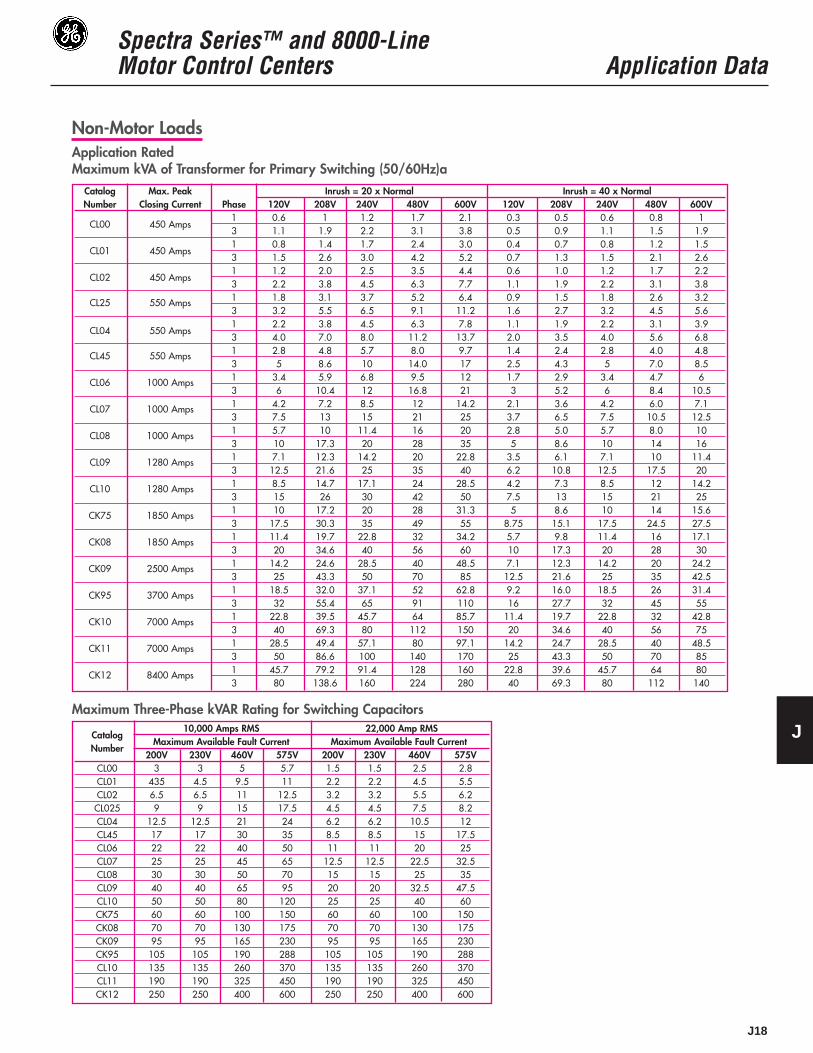
Non-Motor LoadsApplication RatedMaximum kVA of Transformer for Primary Switching (50/60Hz)a
Maximum Three-Phase kVAR Rating for Switching Capacitors
Catalog Max. Peak Inrush = 20 x Normal Inrush = 40 x NormalNumber Closing Current Phase 120V 208V 240V 480V 600V 120V 208V 240V 480V 600V
CL00 450 Amps1 0.6 1 1.2 1.7 2.1 0.3 0.5 0.6 0.8 13 1.1 1.9 2.2 3.1 3.8 0.5 0.9 1.1 1.5 1.9
CL01 450 Amps1 0.8 1.4 1.7 2.4 3.0 0.4 0.7 0.8 1.2 1.53 1.5 2.6 3.0 4.2 5.2 0.7 1.3 1.5 2.1 2.6
CL02 450 Amps1 1.2 2.0 2.5 3.5 4.4 0.6 1.0 1.2 1.7 2.23 2.2 3.8 4.5 6.3 7.7 1.1 1.9 2.2 3.1 3.8
CL25 550 Amps 1 1.8 3.1 3.7 5.2 6.4 0.9 1.5 1.8 2.6 3.23 3.2 5.5 6.5 9.1 11.2 1.6 2.7 3.2 4.5 5.6
CL04 550 Amps1 2.2 3.8 4.5 6.3 7.8 1.1 1.9 2.2 3.1 3.93 4.0 7.0 8.0 11.2 13.7 2.0 3.5 4.0 5.6 6.8
CL45 550 Amps 1 2.8 4.8 5.7 8.0 9.7 1.4 2.4 2.8 4.0 4.83 5 8.6 10 14.0 17 2.5 4.3 5 7.0 8.5
CL06 1000 Amps 1 3.4 5.9 6.8 9.5 12 1.7 2.9 3.4 4.7 63 6 10.4 12 16.8 21 3 5.2 6 8.4 10.5
CL07 1000 Amps 1 4.2 7.2 8.5 12 14.2 2.1 3.6 4.2 6.0 7.13 7.5 13 15 21 25 3.7 6.5 7.5 10.5 12.5
CL08 1000 Amps 1 5.7 10 11.4 16 20 2.8 5.0 5.7 8.0 103 10 17.3 20 28 35 5 8.6 10 14 16
CL09 1280 Amps 1 7.1 12.3 14.2 20 22.8 3.5 6.1 7.1 10 11.43 12.5 21.6 25 35 40 6.2 10.8 12.5 17.5 20
CL10 1280 Amps 1 8.5 14.7 17.1 24 28.5 4.2 7.3 8.5 12 14.23 15 26 30 42 50 7.5 13 15 21 25
CK75 1850 Amps 1 10 17.2 20 28 31.3 5 8.6 10 14 15.63 17.5 30.3 35 49 55 8.75 15.1 17.5 24.5 27.5
CK08 1850 Amps 1 11.4 19.7 22.8 32 34.2 5.7 9.8 11.4 16 17.13 20 34.6 40 56 60 10 17.3 20 28 30
CK09 2500 Amps 1 14.2 24.6 28.5 40 48.5 7.1 12.3 14.2 20 24.23 25 43.3 50 70 85 12.5 21.6 25 35 42.5
CK95 3700 Amps 1 18.5 32.0 37.1 52 62.8 9.2 16.0 18.5 26 31.43 32 55.4 65 91 110 16 27.7 32 45 55
CK10 7000 Amps 1 22.8 39.5 45.7 64 85.7 11.4 19.7 22.8 32 42.83 40 69.3 80 112 150 20 34.6 40 56 75
CK11 7000 Amps 1 28.5 49.4 57.1 80 97.1 14.2 24.7 28.5 40 48.53 50 86.6 100 140 170 25 43.3 50 70 85
CK12 8400 Amps 1 45.7 79.2 91.4 128 160 22.8 39.6 45.7 64 803 80 138.6 160 224 280 40 69.3 80 112 140
Catalog10,000 Amps RMS 22,000 Amp RMS
NumberMaximum Available Fault Current Maximum Available Fault Current
200V 230V 460V 575V 200V 230V 460V 575VCL00 3 3 5 5.7 1.5 1.5 2.5 2.8CL01 435 4.5 9.5 11 2.2 2.2 4.5 5.5CL02 6.5 6.5 11 12.5 3.2 3.2 5.5 6.2CL025 9 9 15 17.5 4.5 4.5 7.5 8.2CL04 12.5 12.5 21 24 6.2 6.2 10.5 12CL45 17 17 30 35 8.5 8.5 15 17.5CL06 22 22 40 50 11 11 20 25CL07 25 25 45 65 12.5 12.5 22.5 32.5CL08 30 30 50 70 15 15 25 35CL09 40 40 65 95 20 20 32.5 47.5CL10 50 50 80 120 25 25 40 60CK75 60 60 100 150 60 60 100 150CK08 70 70 130 175 70 70 130 175CK09 95 95 165 230 95 95 165 230CK95 105 105 190 288 105 105 190 288CL10 135 135 260 370 135 135 260 370CL11 190 190 325 450 190 190 325 450CK12 250 250 400 600 250 250 400 600
Spectra Series™ and 8000-LineMotor Control Centers Application Data
J19
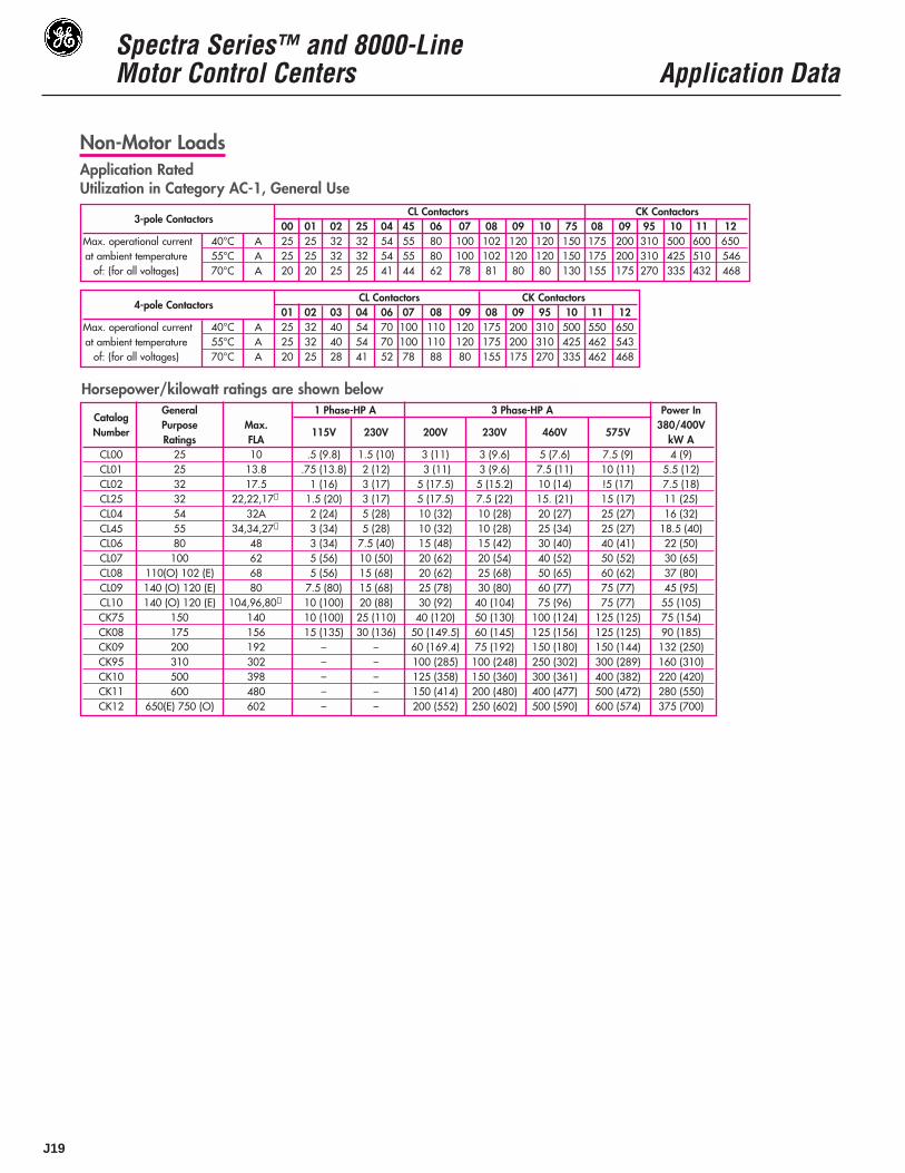
Non-Motor LoadsApplication RatedUtilization in Category AC-1, General Use
3-pole ContactorsCL Contactors CK Contactors
00 01 02 25 04 45 06 07 08 09 10 75 08 09 95 10 11 12Max. operational current 40°C A 25 25 32 32 54 55 80 100 102 120 120 150 175 200 310 500 600 650at ambient temperature 55°C A 25 25 32 32 54 55 80 100 102 120 120 150 175 200 310 425 510 546
of: (for all voltages) 70°C A 20 20 25 25 41 44 62 78 81 80 80 130 155 175 270 335 432 468
4-pole ContactorsCL Contactors CK Contactors
01 02 03 04 06 07 08 09 08 09 95 10 11 12Max. operational current 40°C A 25 32 40 54 70 100 110 120 175 200 310 500 550 650at ambient temperature 55°C A 25 32 40 54 70 100 110 120 175 200 310 425 462 543
of: (for all voltages) 70°C A 20 25 28 41 52 78 88 80 155 175 270 335 462 468
Horsepower/kilowatt ratings are shown below
CatalogGeneral 1 Phase-HP A 3 Phase-HP A Power In
NumberPurpose Max. 380/400VRatings FLA
115V 230V 200V 230V 460V 575VkW A
CL00 25 10 .5 (9.8) 1.5 (10) 3 (11) 3 (9.6) 5 (7.6) 7.5 (9) 4 (9)CL01 25 13.8 .75 (13.8) 2 (12) 3 (11) 3 (9.6) 7.5 (11) 10 (11) 5.5 (12)CL02 32 17.5 1 (16) 3 (17) 5 (17.5) 5 (15.2) 10 (14) !5 (17) 7.5 (18)CL25 32 22,22,17➀ 1.5 (20) 3 (17) 5 (17.5) 7.5 (22) 15. (21) 15 (17) 11 (25)CL04 54 32A 2 (24) 5 (28) 10 (32) 10 (28) 20 (27) 25 (27) 16 (32)CL45 55 34,34,27➀ 3 (34) 5 (28) 10 (32) 10 (28) 25 (34) 25 (27) 18.5 (40)CL06 80 48 3 (34) 7.5 (40) 15 (48) 15 (42) 30 (40) 40 (41) 22 (50)CL07 100 62 5 (56) 10 (50) 20 (62) 20 (54) 40 (52) 50 (52) 30 (65)CL08 110(O) 102 (E) 68 5 (56) 15 (68) 20 (62) 25 (68) 50 (65) 60 (62) 37 (80)CL09 140 (O) 120 (E) 80 7.5 (80) 15 (68) 25 (78) 30 (80) 60 (77) 75 (77) 45 (95)CL10 140 (O) 120 (E) 104,96,80➀ 10 (100) 20 (88) 30 (92) 40 (104) 75 (96) 75 (77) 55 (105) CK75 150 140 10 (100) 25 (110) 40 (120) 50 (130) 100 (124) 125 (125) 75 (154)CK08 175 156 15 (135) 30 (136) 50 (149.5) 60 (145) 125 (156) 125 (125) 90 (185)CK09 200 192 – – 60 (169.4) 75 (192) 150 (180) 150 (144) 132 (250)CK95 310 302 – – 100 (285) 100 (248) 250 (302) 300 (289) 160 (310)CK10 500 398 – – 125 (358) 150 (360) 300 (361) 400 (382) 220 (420)CK11 600 480 – – 150 (414) 200 (480) 400 (477) 500 (472) 280 (550)CK12 650(E) 750 (O) 602 – – 200 (552) 250 (602) 500 (590) 600 (574) 375 (700)
Spectra Series™ and 8000-LineMotor Control Centers Application Data
J20
J
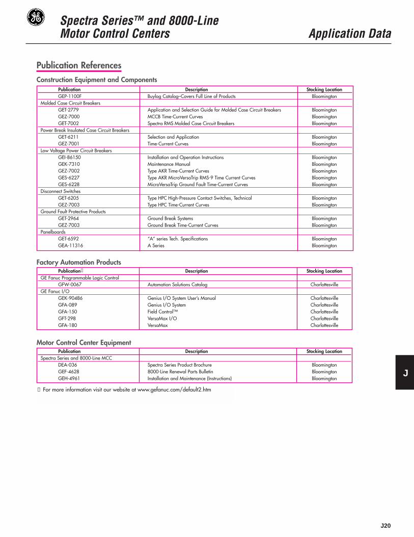
Publication ReferencesConstruction Equipment and Components
Publication Description Stocking LocationGEP-1100F Buylog Catalog–Covers Full Line of Products Bloomington
Molded Case Circuit BreakersGET-2779 Application and Selection Guide for Molded Case Circuit Breakers BloomingtonGEZ-7000 MCCB Time-Current Curves BloomingtonGET-7002 Spectra RMS Molded Case Circuit Breakers Bloomington
Power Break Insulated Case Circuit BreakersGET-6211 Selection and Application BloomingtonGEZ-7001 Time-Current Curves Bloomington
Low Voltage Power Circuit BreakersGEI-86150 Installation and Operation Instructions BloomingtonGEK-7310 Maintenance Manual BloomingtonGEZ-7002 Type AKR Time-Current Curves BloomingtonGES-6227 Type AKR MicroVersaTrip RMS-9 Time Current Curves BloomingtonGES-6228 MicroVersaTrip Ground Fault Time-Current Curves Bloomington
Disconnect SwitchesGET-6205 Type HPC High-Pressure Contact Switches, Technical BloomingtonGEZ-7003 Type HPC Time-Current Curves Bloomington
Ground Fault Protective ProductsGET-2964 Ground Break Systems BloomingtonGEZ-7003 Ground Break Time-Current Curves Bloomington
PanelboardsGET-6592 “A” series Tech. Specifications BloomingtonGEA-11316 A Series Bloomington
Factory Automation ProductsPublication➀ Description Stocking Location
GE Fanuc Programmable Logic ControlGFW-0067 Automation Solutions Catalog Charlottesville
GE Fanuc I/OGEK-90486 Genius I/O System User’s Manual CharlottesvilleGFA-089 Genius I/O System CharlottesvilleGFA-150 Field Control™ CharlottesvilleGFT-298 VersaMax I/O CharlottesvilleGFA-180 VersaMax Charlottesville
Motor Control Center Equipment
➀ For more information visit our website at www.gefanuc.com/default2.htm
Publication Description Stocking LocationSpectra Series and 8000-Line MCC
DEA-036 Spectra Series Product Brochure BloomingtonGEF-4628 8000-Line Renewal Parts Bulletin BloomingtonGEH-4961 Installation and Maintenance (Instructions) Bloomington

Spectra Series™ and 8000-LineMotor Control Centers Application Data
J21
Publication ReferencesGeneral Purpose Controls
Web Access
➀ G11/P11 Drives — www.ge.com/industrialsystem/drives/catalog/af300g11/index.htm
Publication Description Stocking LocationGEP-1260 Control Catalog–Covers Full Line of Products Bloomington
Magnetic Motor StartersGEA-10928 300-Line Magnetic Motor Starters, Descriptive BloomingtonGEH-4756 300-Line Instructions, Nema Size 1, FVNR BloomingtonGEH-4774 300-Line Instructions, Nema Size 2, FVNR BloomingtonGEH-4806 300-Line Instructions, Nema Size 3, FVNR BloomingtonGEH-4789 300-Line Instructions, Nema Size 4, FVNR BloomingtonGEH-4869 300-Line Instructions, Nema Size 5, FVNR BloomingtonGEH-5108 300-Line Instructions, Nema Size 6-9, FVNR BloomingtonGEH-4757 300-Line Instructions, Nema Size 1, FVR and 2-Speed BloomingtonGEH-4775 300-Line Instructions, Nema Size 2, FVR and 2-Speed BloomingtonGEH-4806 300-Line Instructions, Nema Size 3, FVR and 2-Speed BloomingtonGEH-4807 300-Line Instructions, Nema Size 4, FVR and 2-Speed BloomingtonGEH-4839 300-Line Instructions, Nema Size 5, FVR and 2-Speed Bloomington
Pilot DevicesGEA-10877 CR104P Push-buttons and Pilot Lights Bloomington
Relays and TimersGEA-10639 CR122B, CR122BT, Series A Relays BloomingtonGEH-4115 CR120B AC Relays BloomingtonGEH-4120 CR120B Latched Relays BloomingtonGEH-4147 CR122B Time-Delay Relays BloomingtonGEH-4139 CR122BP Time-Delay Relays BloomingtonGEH-6435 Spectra ECM Instructions BloomingtonDET-069 Spectra ECM Product Brochure Bloomington
Variable Speed Drives➀GEI-100364 AF 300P User Guide Fort WayneGEI-100363 AF 300G User Guide Fort Wayne
Solid State StartersDET-024 ASTAT–CD BloomingtonGEH-5951 ASTAT–CD Installation Instructions BloomingtonGEH-6533 ASTAT–CD Service Instructions BloomingtonDEH-195 ASTAT-IBP BloomingtonDEH-208 ASTAT-IBP Service Instructions Bloomington

Spectra Series™ and 8000-LineMotor Control Centers Application Data
J22
Rules of Thumb (Approximation) Defining the Load
Conversion Formulas
kVAR Calculation When Motor Operating
Electrical Data
At 1800 RPM, a motor develops a 3 lb. – ft. per HP.
At 1200 RPM, a motor develops 4.5 lb – ft. per HP.At 460 volts, a 3-phase motor draws 1.25 amp per HP.At 230 volts, a 3-phase motor draws 2.5 amp per HP.
To find Alternating Current Three-PhaseAmperes when HP x 746
Horsepower is known 1.73 x V x Eff x fpAmperes when Kw x 1000
Kilowatts is known 1.73 x V x pfAmperes when Kva x 1000Kva is known 1.73 x V
Kilowatts 1.73 x A x V x pf1000
Kva 1.73 x A x V1000
Horsepower - 1.73 x A x V x Eff x pf(Output) 746
KW (alternating current) = KVA x Power FactorKW (direct current) = V x A x .001
KWH = KW x HoursHP = KW
Motor Efficiency
Rotating Motion Linear MotionHorsepower
HP = T x N HP = F x V5250 33,000
Where: T = Torque (lb-ft) Where: F = Force or Tension (lb)N = Speed (RPM) V = Velocity (FPM)
HP = T x N HP = F x V63,000 396,000
Where: T = Torque (lb-in) Where: F = Force or Tension (lb)N = Speed (RPM) V = Velocity (in/min)
Accelerating Torque/ForceTA = WK2 x N FA = W x V
308t 1933t
Where: TA = Accelerating torque (lb ft)Where: FA = Accelerating Force (lb-ft)WK2 = Total system inertia that W = Weight (lb)
must be accelerated. V = Change in velocity (FPM)This includes motor rotor, t = Time (sec.)speed reducer (if used),and load. (lb-ft2)
TorqueT = F x R
Where: T = Torque (lb-ft)F = Force (lb)R = Radius (ft)
WK2 – reflected
Reflected WK2 = WK2 of Load(Reduction Ratio)2
This is for either belt or gear reductions.
FPM to RPM
RPM = FPM.262 x (diameter in inches)
Motor horsepower output may also be calculated as follows:
HP = V x A x Pf x EFF746
Ohms LawI=E/RR=E/IE=IXRP=IXEP=IXIXR
ValuesV=VoltsA or I = Amperes (amps)Work/P = Watts/PowerKW=KilowattsKwH=Kilowatt HoursKVA=Kilovolt AmperesPf=Power Factor, TablePh= Phase Factor, Table
Characteristics are KnownIf motor HP, full-load power factor (PF) and efficiency (eff) areknown, its easy to calculate the correct kVAR necessary toimprove PF to any value.
Example: 75HP, 3600 RPN, NEMA B motor with full-load PF of 87% and eff. of92% corrected to 95%PF
Original PF = .87 Cos: Tan: = .567Desired PF = .95 = Cos: Tan: = .329
Difference = .238
KW = HPx.746 or 75x.746 = 62Eff. .902
.238 X 62 = 14.8 kVAR (use 15 kVAR)
J
Spectra Series™ and 8000-LineMotor Control Centers Application Data
J23
J
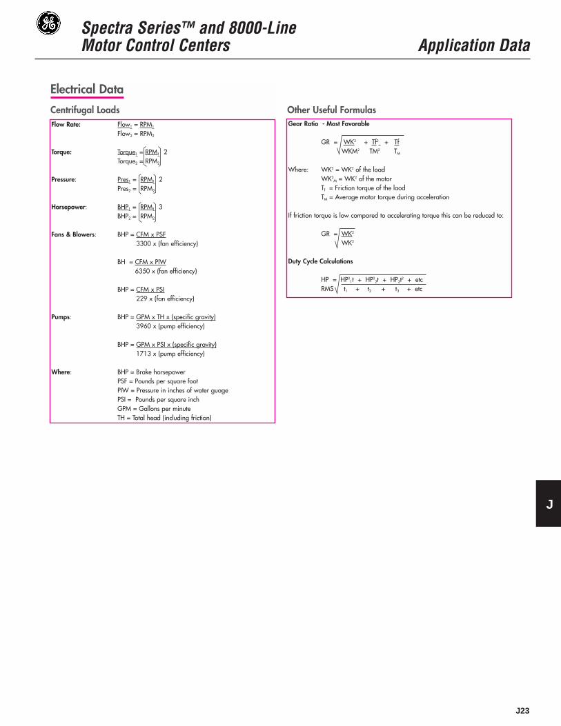
Electrical Data
Gear Ratio - Most Favorable
GR = WK2 + Tf2 + TfWKM2 TM2 TM
Where: WK2 = WK2 of the loadWK2
M = WK2 of the motorTf = Friction torque of the laodTM = Average motor torque during acceleration
If friction torque is low compared to accelerating torque this can be reduced to:
GR = WK2
WK2
Duty Cycle Calculations
HP = HP21t + HP2
2t + HP3t2 + etcRMS t1 + t2 + t3 + etc
Centrifugal Loads Other Useful FormulasFlow Rate: Flow1 = RPM1
Flow2 = RPM2
Torque: Torque1 = RPM1 2Torque2 = RPM2
Pressure: Pres1 = RPM1 2Pres2 = RPM2
Horsepower: BHP1 = RPM1 3BHP2 = RPM2
Fans & Blowers: BHP = CFM x PSF3300 x (fan efficiency)
BH = CFM x PIW6350 x (fan efficiency)
BHP = CFM x PSI229 x (fan efficiency)
Pumps: BHP = GPM x TH x (specific gravity)3960 x (pump efficiency)
BHP = GPM x PSI x (specific gravity)1713 x (pump efficiency)
Where: BHP = Brake horsepowerPSF = Pounds per square footPIW = Pressure in inches of water guagePSI = Pounds per square inchGPM = Gallons per minuteTH = Total head (including friction)