spectrum processing for total dominance · pdf filed-ta offers readily customizable...
TRANSCRIPT
Spectrum Processing for Total Dominance
D-TA SYSTEMS INC
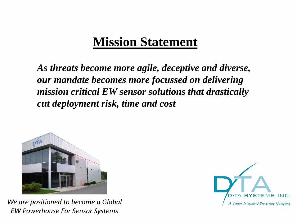
Mission Statement
As threats become more agile, deceptive and diverse,
our mandate becomes more focussed on delivering
mission critical EW sensor solutions that drastically
cut deployment risk, time and cost
We are positioned to become a Global EW Powerhouse For Sensor Systems

10 Gigabit Sensor Processing
FAST, SCALABLE AND SYNCHRONIZED
D-TA pioneered 10 Gigabit Sensor Processing which has simplified sensor system
development. Any system now has only two parts: Sensor interface (D-TA products)
& processor (typically commercially available low-cost server class computer). One
or more 10 Gigabit networks (fibers) move data from one to another.
• Simple & low-cost solution for rapid deployment (D-TA provides the Sensor
Interface subsystems for different applications and the user only develops
application software )
• Scalable solution, as channel-count & BW increases more fibers can be used
• Use of Optical fibers allow sensor interface & processor to be far apart (antenna-
level digitization is possible)
• OS agnostic
All D-TA Sensor Interface Products Use 10 Gigabit Optical Networks As Data Backbone

D-TA offers readily customizable open-architecture sensor systems for EW applications. D-TA’s products have been deployed in wide ranging applications from COMINT to SONAR.
COMINT
ELINT
RADAR
SONAR
EW Emitter SIMULATION
• Portable Solution for RF spectral surveillance, real-time RF recording & playback, Search Receiver
• Multi-Antenna transceiver solutions for ES, DF, COMS & EA
• Ultra-wideband RF transceiver for ELINT Pulse Processing, Data Collection & Data Management
• Cognitive Radar in the L, S, C, X & K bands, Passive Radar, Over-The Horizon Phased Array HF Radar
• COMINT, ELINT & Radar Simulation
• ASW, Mine, Dipping Sonar & Sonobuoy Processing
• DC to daylight spectrum processing for spectrum dominance SPECTRUM FUSION
Deployed Applications At-A-Glance

COMINT Portable RF Record/Playback, Simulation, Search Receiver
5
1GbE
• 1 Rx & 1 Tx or 2 Rx or 2 Tx • 1 MHz – 8 GHz with 40/80 MHz IBW • 8 dB NF, & 93 dB Gain Control • 16 Bit data converters • FPGA based programmable DDC &
DUC for BW selection from 5 kHz to 40/80 MHz
• 2 TB SSDs for real-time record & playback
RFvision1-Supermini
Fielded Applications: • RF Recording & Playback • Spectrum Monitoring • EW Simulation • Search Receiver with Automatic
Modulation Recognition & Demodulation & Decoding
RFvision1-Supermini [7.64”x7.5”x12.76” ; 8.1 kg
& 2xSSDs]

UNMANNED AERIAL RF MONITORING
(UnARM) / TARGET ACQUISITION & JAMMING
RFvision1-Supermini
Unmanned Aircraft System
RFvision1-Supermini can be mounted on a small UAS for spectral surveillance and also jamming (requires external power amp)

RFvision1-Supermini For Portable Dual Channel Arbitrary RF Waveform Generator
For Communications & Radar Signals
Sonobuoy Receiver Signal
(32 FM channels)
Weighted OFDM signal
Examples of Complex Signal Generation
Streaming I/Q Data from hard drives to tunable RF transmitters simplifies RF signal generation. D-TA’s Communication and Radar signal builder GUI creates waveform data files and stores them in the hard drives
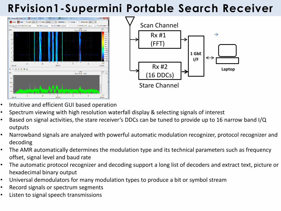
RFvision1-Supermini Portable Search Receiver
Rx #1 (FFT)
Rx #2 (16 DDCs)
1 GbE I/F
Laptop
• Intuitive and efficient GUI based operation • Spectrum viewing with high resolution waterfall display & selecting signals of interest • Based on signal activities, the stare receiver’s DDCs can be tuned to provide up to 16 narrow band I/Q
outputs • Narrowband signals are analyzed with powerful automatic modulation recognizer, protocol recognizer and
decoding • The AMR automatically determines the modulation type and its technical parameters such as frequency
offset, signal level and baud rate • The automatic protocol recognizer and decoding support a long list of decoders and extract text, picture or
hexadecimal binary output • Universal demodulators for many modulation types to produce a bit or symbol stream • Record signals or spectrum segments • Listen to signal speech transmissions
Scan Channel
Stare Channel
RADIO HEAD
3-5 Channels in
½ ATR
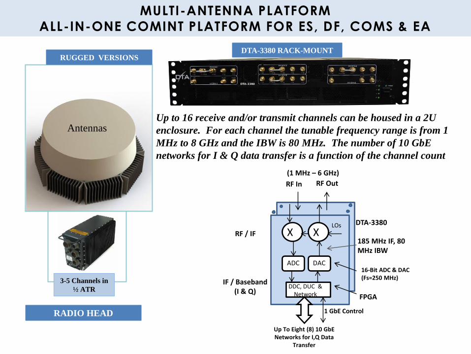
MULTI-ANTENNA PLATFORM
ALL-IN-ONE COMINT PLATFORM FOR ES, DF, COMS & EA
Antennas
DTA-3380 RACK-MOUNT RUGGED VERSIONS
Up to 16 receive and/or transmit channels can be housed in a 2U
enclosure. For each channel the tunable frequency range is from 1
MHz to 8 GHz and the IBW is 80 MHz. The number of 10 GbE
networks for I & Q data transfer is a function of the channel count
X
(1 MHz – 6 GHz)
ADC DAC
FPGA
185 MHz IF, 80 MHz IBW
Up To Eight (8) 10 GbE Networks for I,Q Data
Transfer
RF / IF
IF / Baseband (I & Q)
DDC, DUC & Network
X LOs
16-Bit ADC & DAC (Fs=250 MHz)
RF In RF Out
1 GbE Control
DTA-3380
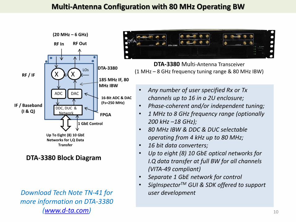
Multi-Antenna Configuration with 80 MHz Operating BW
X
(20 MHz – 6 GHz)
ADC DAC
FPGA
185 MHz IF, 80 MHz IBW
Up To Eight (8) 10 GbE Networks for I,Q Data
Transfer
RF / IF
IF / Baseband (I & Q)
DDC, DUC & Network
X LOs
16-Bit ADC & DAC (Fs=250 MHz)
RF In RF Out
1 GbE Control
DTA-3380
DTA-3380 Block Diagram
DTA-3380 Multi-Antenna Transceiver (1 MHz – 8 GHz frequency tuning range & 80 MHz IBW)
• Any number of user specified Rx or Tx channels up to 16 in a 2U enclosure;
• Phase-coherent and/or independent tuning; • 1 MHz to 8 GHz frequency range (optionally
200 kHz –18 GHz); • 80 MHz IBW & DDC & DUC selectable
operating from 4 kHz up to 80 MHz; • 16 bit data converters; • Up to eight (8) 10 GbE optical networks for
I.Q data transfer at full BW for all channels (VITA-49 compliant)
• Separate 1 GbE network for control • SigInspectorTM GUI & SDK offered to support
user development
10
Download Tech Note TN-41 for more information on DTA-3380
(www.d-ta.com)

User Defined Configuration Of DTA-3380 For COMINT
A DTA-3380 example configuration for ES, DF, COMS & EA
DTA-3380
• 1 MHz – 8 GHz Spectral Coverage & 80 MHz IBW
• Up To 16 Phase-Coherent and/or independently tuned channels
• 8 dB Noise Figure, >+30 dBm OIP3, 93 dB Gain Control & 16 Bit Data Converters
• DDC programmed Operating BW selection From a few kHz to 80 MHz
• K-7 FPGAs (User Programmable)
• Multiple 10 GbE Optical Networks for Data Transfers for Server Based Processing

RFvision-Broadview With Integrated Processing & Record / Playback
DTA-5000 (24 TB SSDs)
Replicated 10 GbE Link To an Optional Processing Server
RAID Server
RFvision-Broadview (DTA-3380 RF Transceiver & DTA-5000 RAID Server)
DTA-3380
Typical DF Processing (Simultaneous Recording & Processing)
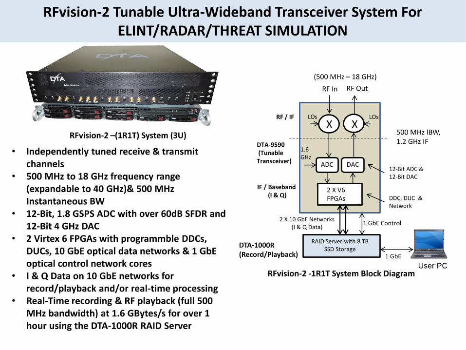
X
(500 MHz – 18 GHz)
ADC DAC
2 X V6 FPGAs
500 MHz IBW, 1.2 GHz IF
2 X 10 GbE Networks (I & Q Data)
RAID Server with 8 TB SSD Storage
RF / IF
IF / Baseband (I & Q)
DTA-1000R (Record/Playback)
DDC, DUC & Network
RFvision-2 -1R1T System Block Diagram
1.6 GHz
LOs
DTA-9590 (Tunable Transceiver)
12-Bit ADC & 12-Bit DAC
RF In
1 GbE Control
1 GbE
User PC
X
RF Out
LOs
RFvision-2 –(1R1T) System (3U)
RFvision-2 Tunable Ultra-Wideband Transceiver System For ELINT/RADAR/THREAT SIMULATION
• Independently tuned receive & transmit channels
• 500 MHz to 18 GHz frequency range (expandable to 40 GHz)& 500 MHz Instantaneous BW
• 12-Bit, 1.8 GSPS ADC with over 60dB SFDR and 12-Bit 4 GHz DAC
• 2 Virtex 6 FPGAs with programmble DDCs, DUCs, 10 GbE optical data networks & 1 GbE optical control network cores
• I & Q Data on 10 GbE networks for record/playback and/or real-time processing
• Real-Time recording & RF playback (full 500 MHz bandwidth) at 1.6 GBytes/s for over 1 hour using the DTA-1000R RAID Server

Multi-Function ELINT With Advanced Pulse Processing, Data Collection & Data Reduction
RFvision-2-MFEL
Frequency range: 0.5 – 18 GHz Instaneous bandwidth: 500 MHz Noise Figure: 14 dB; SFDR: 63 dB Gain Control: 31 dB in steps of 1 dB Dynamic range: 63dB PW resolution: 1.875 ns MOPs Recognition : FMOP - Linear and non-linear; PMOP - Bi-phase, multi-phase, Barker, Storage: Up To 24 TB
The key differences in the design of the MFEL system over other ELINT system in the market is that it is based on processing recorded (wideband I/Q) data and as result every sample is scrutinized for the highest probability of intercept and more accurate analysis. Processing happens concurrently as data being recorded in multi-core software environment
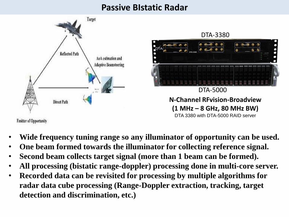
DTA-3380
(N-Channel Rx)
DTA-5000
N-Channel RFvision-Broadview
(1 MHz – 8 GHz, 80 MHz BW) DTA 3380 with DTA-5000 RAID server
• Wide frequency tuning range so any illuminator of opportunity can be used.
• One beam formed towards the illuminator for collecting reference signal.
• Second beam collects target signal (more than 1 beam can be formed).
• All processing (bistatic range-doppler) processing done in multi-core server.
• Recorded data can be revisited for processing by multiple algorithms for
radar data cube processing (Range-Doppler extraction, tracking, target
detection and discrimination, etc.)
Passive BIstatic Radar
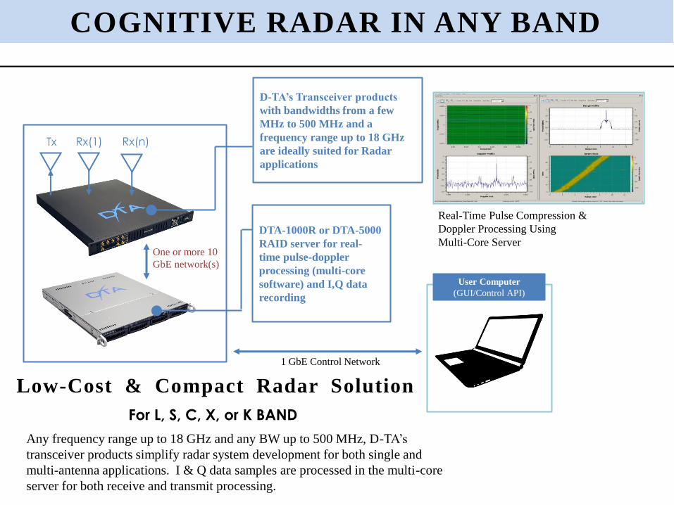
Rx(1) Tx Rx(n)
Real-Time Pulse Compression &
Doppler Processing Using
Multi-Core Server
Low-Cost & Compact Radar Solution
COGNITIVE RADAR IN ANY BAND
D-TA’s Transceiver products
with bandwidths from a few
MHz to 500 MHz and a
frequency range up to 18 GHz
are ideally suited for Radar
applications
DTA-1000R or DTA-5000
RAID server for real-
time pulse-doppler
processing (multi-core
software) and I,Q data
recording
User Computer
(GUI/Control API)
One or more 10
GbE network(s)
1 GbE Control Network
Any frequency range up to 18 GHz and any BW up to 500 MHz, D-TA’s
transceiver products simplify radar system development for both single and
multi-antenna applications. I & Q data samples are processed in the multi-core
server for both receive and transmit processing.
For L, S, C, X, or K BAND

Over the Horizon Radar (OTHR) –Phased Array HF Radar
DTA-2300S
DTA-3200H
DTA-2300S
DTA-3200H
DTA-2300S
DTA-3200H
DTA-2300S
DTA-3200H
Long Range 10GbE fiber
• 1 MHz to 30 MHz coverage with front-end HF band splitting option for high sensitivity HF operation (see block diagram)
• Fully differential amplification for 2nd harmonic distortion reduction
• Programmable 31-dB attenuator in steps of 1dB for gain balance and spurious management
• Full Transceive Operation
• 90 dB SFDR • Optical 10GbE network allow long distance
transmission with LR optics • Lengths up to 10km possible • A cluster of 16 or more channels can be placed
in a single location -- improving sensitivity • Multiple clusters may be spaced out to match
with the actual antenna placement • Digitized data can be transmitted to common
recording / processing station • Reduces deployment cost and improves RF
sensitivity
A 128-channel HF Phased Array Radar system was y delivered to DRDC
Major Features:
HF Conditioning
HF To Baseband (I & Q)
Processing / Recording
17

Synthetic Emitter Simulation For Test & Training
US Army COMINT Simulation using D-TA’s RFvsiion1 series products
EW Testing in mid-ocean using UAV equipped with D-TA’s EW Emulator
Streaming Waveform I/Q Data from computer hard drive to tunable RF transmitter simplifies RF signal emulation. Any waveform for virtually any duration can be created
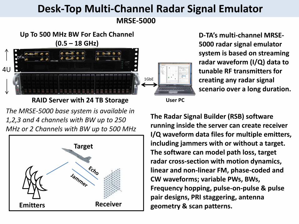
MRSE-5000
1GbE
User PC RAID Server with 24 TB Storage
Up To 500 MHz BW For Each Channel (0.5 – 18 GHz)
4U
D-TA’s multi-channel MRSE-5000 radar signal emulator system is based on streaming radar waveform (I/Q) data to tunable RF transmitters for creating any radar signal scenario over a long duration.
Emitters
Target
Receiver
The Radar Signal Builder (RSB) software running inside the server can create receiver I/Q waveform data files for multiple emitters, including jammers with or without a target. The software can model path loss, target radar cross-section with motion dynamics, linear and non-linear FM, phase-coded and CW waveforms; variable PWs, BWs, Frequency hopping, pulse-on-pulse & pulse pair designs, PRI staggering, antenna geometry & scan patterns.
The MRSE-5000 base system is available in 1,2,3 and 4 channels with BW up to 250 MHz or 2 Channels with BW up to 500 MHz
Desk-Top Multi-Channel Radar Signal Emulator

DTA-4100 (19” rack-mount 1U)
can be configured for up to
72 receive or transmit channels
or up to 36 receive & 36 transmit
channels
DTA-4100 Receive Sub-System:
• 36 Differential Inputs with Signal Conditioning
• 24-Bit, 2.5 MHz Sigma-Delta ADCs that offer
over 108 dB SFDR
• Two DAC outputs that can be used for
test/transmit
• Multiple DTA-4100 receive subsystems can be
stacked to increase channel count
• 10 GbE Optical Link allows full bandwidth
operation
DTA-1000R (1U) Server for Processing,
Recording & Playback and Display
DTA-4100 Transmit Sub-System:
• 36 Differential Outputs with Signal Conditioning
• 16-Bit, 50 MHz DACs that offer over 88 dB
SFDR
• Two ADC inputs that can be used for test
• Multiple DTA-4100 transmit subsystems can be
stacked to increase channel count
• 10 GbE Optical Link allows full bandwidth
operation
MULTI-CHANNEL ACOUSTIC
RECEIVE & TRANSMIT PROCESSING
10 GbE Fiber capable of moving
data over long distances

Scaling Up To Handle A Large Number Of Channels
Many acoustic application require processing a large number of
sensors (e.g, sonar), virtually any number of DTA-4100 units
can be operated synchronously to increase channel count.
Sensor Array
Array
I/F
TYPICAL SYSTEM CONFIGURATION
Only optical fibers connect DTA-
4100s to the processor for remote
processing
Synchronized Operation with
N × DTA-4100
LARGE CHANNEL COUNT ACOUSTIC PROCESSING
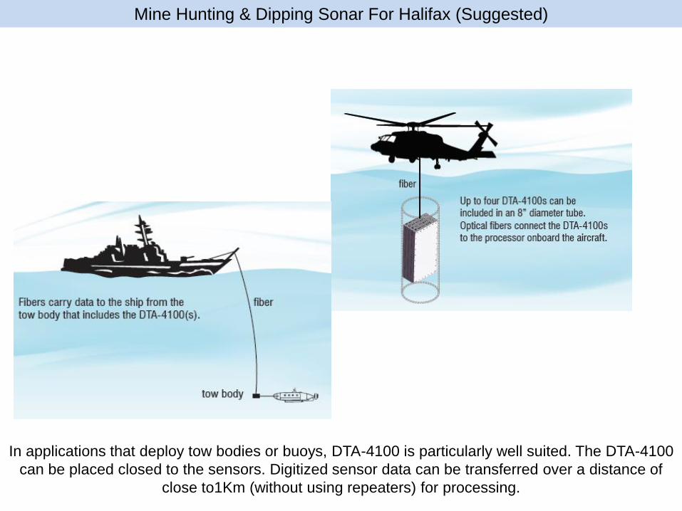
Mine Hunting & Dipping Sonar For Halifax (Suggested)
In applications that deploy tow bodies or buoys, DTA-4100 is particularly well suited. The DTA-4100
can be placed closed to the sensors. Digitized sensor data can be transferred over a distance of
close to1Km (without using repeaters) for processing.

Sonobuoy Receive Processing
D-TA’s RFvision-1 RF receivers simplify Sonobuoy processing of Frequency
Division Multiplexed VHF radio signals from 32, 64 or more buoys
Freq.
Drastic Reduction of Size & Cost
Channelized VHF Receiver
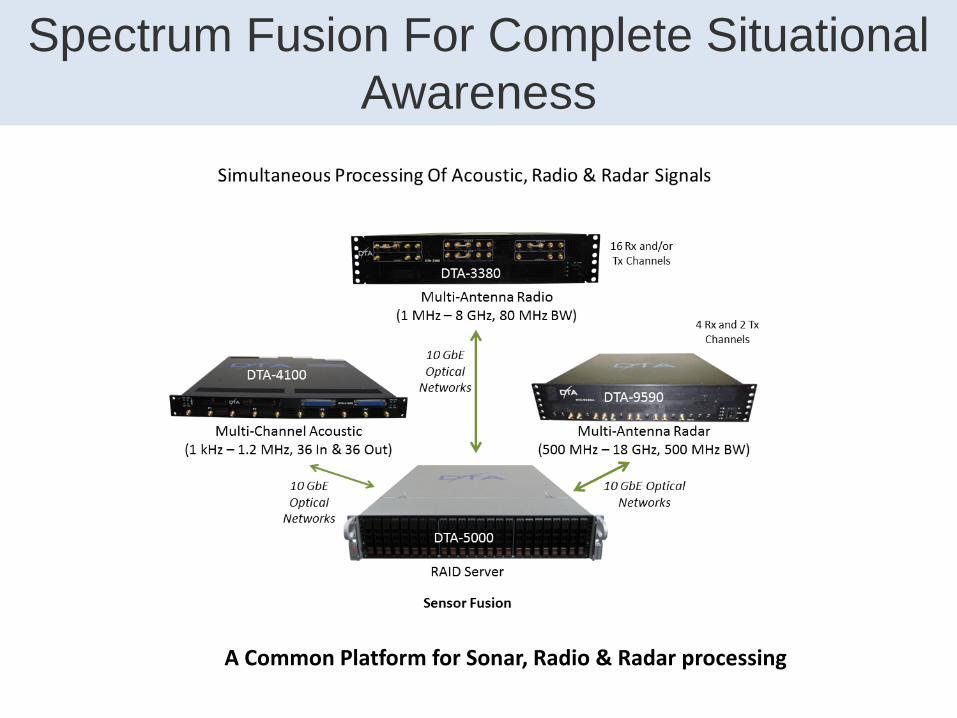
Spectrum Fusion For Complete Situational
Awareness
A Common Platform for Sonar, Radio & Radar processing

For more information Contact [email protected]
https://www.linkedin.com/company/d-ta-systems
United States
D-TA Systems Corp.
8 Inverness Drive East
Suite 250
Centennial, CO 80112
USA
1 877 382 3222
International
D-TA Systems Inc.
2500 Lancaster Road
Ottawa ON
Canada K1B 4S5
1 613 745 8713
Spectrum Processing For Total Dominance!
25