speedfaxtm 2011 - w3.usa.siemens.com · 38 kv gas-insulated metal-clad switchgear 14-19 ... type...
TRANSCRIPT
14SW
ITCHGEAR
Siemens / Speedfax Previous folio: 13-1
SPEEDFAXTM 2011 Switchgear
Residential L Commercial L Industrial
ContentsMedium-Voltage Equipment 14-2 – 14-27 Smart-Gear®PowerDistributionSwitchgearSolution 14-2–14-3
5–15kVTypesGM-SGandGM-SG-ARand 38kVTypeGM38Metal-CladSwitchgear 14-4–14-6
5–15kVTypesGM-SGandGM-SG-ARSwitchgearOverview 14-7–14-15
TypeGM-SGSwitchgear 14-7
Arc-ResistantTypeGM-SG-ARSwitchgear 14-8
TypeGMSGVacuumCircuitBreakers 14-9
TypeGMSGVacuumCircuitBreakerRatings 14-10
TypesGM-SGandGM-SG-ARSwitchgearDimensions 14-11–14-12
TypesGM-SGandGM-SG-ARSwitchgearAccessories 14-13
TypesGM-SGandGM-SG-ARSwitchgearEndViews 14-14–14-15
38kVTypeGM38Metal-CladSwitchgear 14-16–14-18
38kVGas-InsulatedMetal-CladSwitchgear 14-19
5–15–27.6kVTypeSIMOSECMetal-Enclosed,Load-InterrupterSwitchgear 14-20
Series81000™Medium-VoltageControllers(MVC)upto13.8kV 14-21–14-24
MVControllers(MVC)upto7.2kV 14-25
SIPROTECCBIICONTROLLERCircuitBreakerControl 14-26
PowerEquipmentCenters 14-27
Protective Relays & SCADA Systems 14-28 – 14-33 SCADA/SubstationAutomation 14-28
SIPROTECProtectiveRelays 14-29–14-33
Replacement Breakers & Retrofit Products 14-34 – 14-35 Medium-VoltageReplacementCircuitBreakers 14-34
SafetyRackingSolutions 14-35
Field Services 14-36 – 14-39 Start-up/Commissioning/Engineer-by-the-DayServices 14-36–14-37
PowerSystemStudies 14-38
ArcFlashStudy 14-39
Secondary Unit Substations 14-40 – 14-52 Overview 14-40
TypeSIMOSECMetal-EnclosedLoad-InterrupterPrimarySwitch 14-41
High-Voltage(HV)FuseSelectionTable 14-42
Transformers—DryType 14-44–14-45
Transformers—Liquid-FilledType 14-46
TypeWLLow-VoltageSwitchgearSubstationSecondaries 14-47
SwitchboardSubstationSecondaries(SeeSwitchboardSection13) 14-48
TransformerDiagrams 14-49–14-51
Low-Voltage Switchgear 14-52 – 14-68
TypeWLLow-VoltageMetal-EnclosedSwitchgear 14-52–14-58
TypeWLCircuitBreakers 14-59–14-61
TPS3FamilyofHardwiredSurgeProtectiveDevices 14-62
ArcFlashSolutions 14-63–14-68
Allstatements,technicalinformationandrecommendationscontainedhereinarebasedoninformationandtestswebelievetobereliable.Theaccuracyorcompletenesshereofisnotguaranteed.Sinceconditionsofuseareoutsideourcontrol,theusershoulddeterminethesuitabilityoftheproductforitsintendeduseandassumesallriskandliabilitywhatsoeverinconnectionherewith.
Siemens Industry, Inc. SPEEDFAX™ 2011 Product Catalog14-2
14SW
ITCH
GEAR
Medium-Voltage EquipmentSmart-Gear® Power Distribution Switchgear Solution General
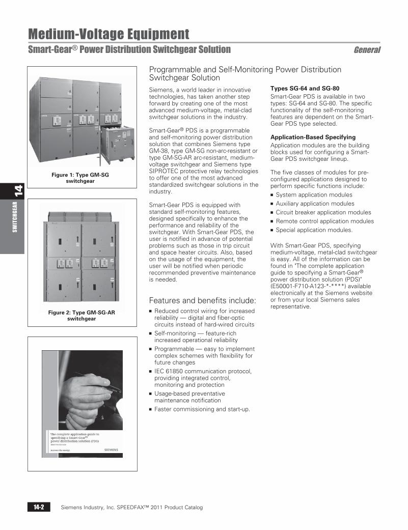
Siemens, a world leader in innovative technologies, has taken another step forward by creating one of the most advanced medium-voltage, metal-clad switchgear solutions in the industry.
Smart-Gear® PDS is a programmable and self-monitoring power distribution solution that combines Siemens type GM-38, type GM-SG non-arc-resistant or type GM-SG-AR arc-resistant, medium-voltage switchgear and Siemens type SIPROTEC protective relay technologies to offer one of the most advanced standardized switchgear solutions in the industry.
Smart-Gear PDS is equipped with standard self-monitoring features, designed specifically to enhance the performance and reliability of the switchgear. With Smart-Gear PDS, the user is notified in advance of potential problems such as those in trip circuit and space heater circuits. Also, based on the usage of the equipment, the user will be notified when periodic recommended preventive maintenance is needed.
Features and benefits include:n Reduced control wiring for increased
reliability — digital and fiber-optic circuits instead of hard-wired circuits
n Self-monitoring — feature-rich increased operational reliability
n Programmable — easy to implement complex schemes with flexibility for future changes
n IEC 61850 communication protocol, providing integrated control, monitoring and protection
n Usage-based preventative maintenance notification
n Faster commissioning and start-up.
Programmable and Self-Monitoring Power Distribution Switchgear Solution
Types SG-64 and SG-80Smart-Gear PDS is available in two types: SG-64 and SG-80. The specific functionality of the self-monitoring features are dependent on the Smart-Gear PDS type selected.
Application-Based SpecifyingApplication modules are the building blocks used for configuring a Smart-Gear PDS switchgear lineup.
The five classes of modules for pre-configured applications designed to perform specific functions include: n System application modulesn Auxiliary application modules n Circuit breaker application modules n Remote control application modules n Special application modules.
With Smart-Gear PDS, specifying medium-voltage, metal-clad switchgear is easy. All of the information can be found in "The complete application guide to specifying a Smart-Gear® power distribution solution (PDS)" (E50001-F710-A123-*-****) available electronically at the Siemens website or from your local Siemens sales representative.
Figure 1: Type GM-SG switchgear
Figure 2: Type GM-SG-AR switchgear
Siemens / Speedfax Previous folio: New from E50001-F710-A141-X-4A00 SS 02/10/11
Siemens Industry, Inc. SPEEDFAX™ 2011 Product Catalog 14-3
14SW
ITCHGEAR
Medium-Voltage EquipmentSmart-Gear® Power Distribution Switchgear Solution General
Table 1: Types SG-64 and SG-80 features
Features available via protective relay devices Type SG-64 Type SG-80
Circuitbreakeroperatingcyclesmonitoring Standard Standard
Circuitbreakertrip-circuitmonitoring Standard Standard
Circuitbreakerclose-circuitmonitoring Standard Notavailable
Vacuuminterrupterwearmonitoring Standard Standard
Integratedcontrols Standard Standard
Circuitbreakerrackingpositionindication Standard Notavailable
Integratedpowermonitoring Standard Standard
Programmablecircuitbreakercontrolinterlocking Optional Optional
Programmablemain-tie-maintransferscheme Optional Optional
Fancoolingmonitoringfor4,000Acircuitbreaker Standard Notavailable
Voltagetransformermonitoring Standard Standard
Currenttransformermonitoring Standard Standard
Busprotection(device50B) Standard Standard
Spaceheateroperationmonitoring Standard Standard
Largeprotectiverelaydisplayscreen Standard Notavailable
IEC61850communicationprotocol(only) Standard Standard
Arc-flashdetection Optional Optional
TypeSG-64Smart-GearPDSisequippedwithtype7SJ6415protectiverelaysonfeeder,mainandtiecir-cuitbreakers.
TypeSG-80Smart-GearPDSisequippedwithtype7SJ8041protectiverelaysonfeedercircuitbreakersandtype7SJ6415protectiverelaysonmainandtiecircuitbreakers.
MOCandTOCarenotrequiredforremotecontrolandmonitoringusingcommunications.
Circuitbreakeroperationprovidedthroughprotectiverelays.Controlswitchesarenotprovided.
AllfunctionsareavailableviaintelligentelectronicdeviceinaSiemensprotectiverelay.
Standardfortype7SJ6415protectiverelaysfurnishedonmaincircuitbreakers.
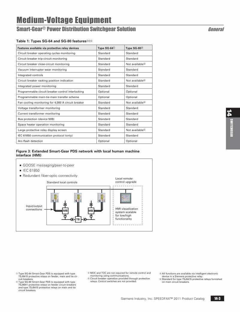
Figure 3: Extended Smart-Gear PDS network with local human machine interface (HMI)
24.06.200324.06.200324.06.200324.06.2003
14:56:22.86414:56:22.88414:56:22.86414:56:22.86414:56:22.864
11:34:12.644
Ring OstRing OstRing OstRing Ost
Ring W est
Rind W est
Vorfertigung
Vorfertigung
Vorfertigung
VorfertigungMontage
Montage
24.06.2003
24.06.200324.06.200324.06.200324.06.200324.06.2003
14:56:22.86414:56:22.88414:56:22.86414:56:22.86414:56:22.864
11:34:12.644
Ring OstRing OstRing OstRing Ost
Ring W est
Rind W est
Vorfertigung
Vorfertigung
Vorfertigung
VorfertigungMontage
Montage
24.06.2003
24.06.200324.06.200324.06.200324.06.200324.06.2003
14:56:22.86414:56:22.88414:56:22.86414:56:22.86414:56:22.864
11:34:12.644
Ring OstRing OstRing OstRing Ost
Ring W est
Rind W est
Vorfertigung
Vorfertigung
Vorfertigung
VorfertigungMontage
Montage
24.06.2003
24.06.200324.06.200324.06.200324.06.200324.06.2003
14:56:22.86414:56:22.88414:56:22.86414:56:22.86414:56:22.864
11:34:12.644
Ring OstRing OstRing OstRing Ost
Ring W est
Rind W est
Vorfertigung
Vorfertigung
Vorfertigung
VorfertigungMontage
Montage
24.06.2003
24.06.200324.06.200324.06.200324.06.200324.06.2003
14:56:22.86414:56:22.88414:56:22.86414:56:22.86414:56:22.864
11:34:12.644
Ring OstRing OstRing OstRing Ost
Ring W est
Rind W est
Vorfertigung
Vorfertigung
Vorfertigung
VorfertigungMontage
Montage
24.06.2003
24.06.200324.06.200324.06.200324.06.200324.06.2003
14:56:22.86414:56:22.88414:56:22.86414:56:22.86414:56:22.864
11:34:12.644
Ring OstRing OstRing OstRing Ost
Ring W est
Rind W est
Vorfertigung
Vorfertigung
Vorfertigung
VorfertigungMontage
Montage
24.06.2003
24.06.2003
n GOOSE messaging/peer-to-peern IEC 61850n Redundant fiber-optic connectivity
Localremotecontrolupgrade
HMIvisualizationsystemscalableforlow/highfunctionality
Input/outputconnections
Standardlocalcontrols
TB
MBMB
Siemens / Speedfax Previous folio: New from E50001-F710-A141-X-4A00 SS 02/10/11
Siemens Industry, Inc. SPEEDFAX™ 2011 Product Catalog14-4
14SW
ITCH
GEAR
Siemens / Speedfax Previous folio: 13-2 SS 02/08/11
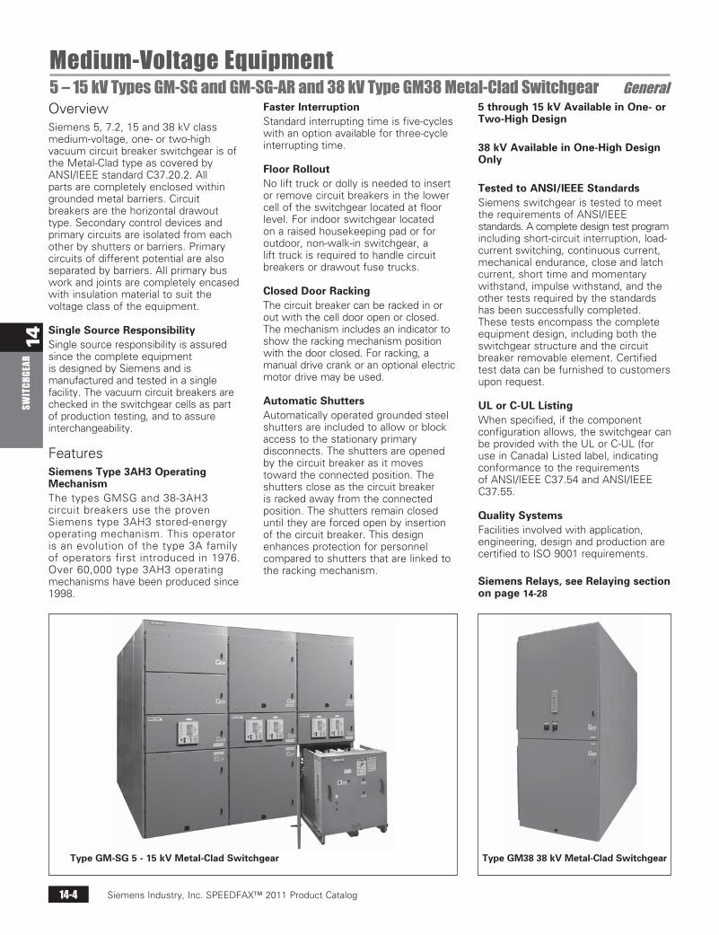
Medium-Voltage Equipment5 – 15 kV Types GM-SG and GM-SG-AR and 38 kV Type GM38 Metal-Clad Switchgear GeneralOverviewSiemens 5, 7.2, 15 and 38 kV class medium-voltage, one- or two-high vacuum circuit breaker switchgear is of the Metal-Clad type as covered by ANSI/IEEE standard C37.20.2. All parts are completely enclosed within grounded metal barriers. Circuit breakers are the horizontal drawout type. Secondary control devices and primary circuits are isolated from each other by shutters or barriers. Primary circuits of different potential are also separated by barriers. All primary bus work and joints are completely encased with insulation material to suit the voltage class of the equipment.
Single Source ResponsibilitySingle source responsibility is assured since the complete equipment is designed by Siemens and is manufactured and tested in a single facility. The vacuum circuit breakers are checked in the switchgear cells as part of production testing, and to assure interchangeability.
FeaturesSiemens Type 3AH3 Operating MechanismThe types GMSG and 38-3AH3 circuit breakers use the proven Siemens type 3AH3 stored-energy operating mechanism. This operator is an evolution of the type 3A family of operators first introduced in 1976. Over 60,000 type 3AH3 operating mechanisms have been produced since 1998.
Faster InterruptionStandard interrupting time is five-cycles with an option available for three-cycle interrupting time.
Floor RolloutNo lift truck or dolly is needed to insert or remove circuit breakers in the lower cell of the switchgear located at floor level. For indoor switchgear located on a raised housekeeping pad or for outdoor, non-walk-in switchgear, a lift truck is required to handle circuit breakers or drawout fuse trucks.
Closed Door RackingThe circuit breaker can be racked in or out with the cell door open or closed. The mechanism includes an indicator to show the racking mechanism position with the door closed. For racking, a manual drive crank or an optional electric motor drive may be used.
Automatic ShuttersAutomatically operated grounded steel shutters are included to allow or block access to the stationary primary disconnects. The shutters are opened by the circuit breaker as it moves toward the connected position. The shutters close as the circuit breaker is racked away from the connected position. The shutters remain closed until they are forced open by insertion of the circuit breaker. This design enhances protection for personnel compared to shutters that are linked to the racking mechanism.
5 through 15 kV Available in One- or Two-High Design
38 kV Available in One-High Design Only
Tested to ANSI/IEEE StandardsSiemens switchgear is tested to meet the requirements of ANSI/IEEE standards. A complete design test program including short-circuit interruption, load-current switching, continuous current, mechanical endurance, close and latch current, short time and momentary withstand, impulse withstand, and the other tests required by the standards has been successfully completed. These tests encompass the complete equipment design, including both the switchgear structure and the circuit breaker removable element. Certified test data can be furnished to customers upon request.
UL or C-UL ListingWhen specified, if the component configuration allows, the switchgear can be provided with the UL or C-UL (for use in Canada) Listed label, indicating conformance to the requirements of ANSI/IEEE C37.54 and ANSI/IEEE C37.55.
Quality SystemsFacilities involved with application, engineering, design and production are certified to ISO 9001 requirements.
Siemens Relays, see Relaying section on page 14-28
Type GM38 38 kV Metal-Clad SwitchgearType GM-SG 5 - 15 kV Metal-Clad Switchgear
Siemens Industry, Inc. SPEEDFAX™ 2011 Product Catalog 14-5
14SW
ITCHGEAR
Siemens / Speedfax Previous folio: 13-3 SS 02/08/11
Medium Voltage Equipment5 – 15 kV Types GM-SG and GM-SG-AR and 38 kV Type GM38 Metal-Clad Switchgear GeneralSiemens types GM-SG and GM-SG-AR 5, 7.2 and 15 kV and type GM38 38 kV metal-clad power switchgear assemblies with horizontal drawout vacuum circuit breakers take advantage of the latest developments in vacuum interrupter technology. Up to two circuit breakers can be stacked in a single vertical section, allowing significant space savings in the types GM-SG and GM-SG-AR switchgear. In the type GM38 switchgear, circuit breaker are available only in the lower compartment.
The equipment meets or exceeds the latest standards of ANSI, IEEE and NEMA.
Types GM-SG, GM-SG-AR and GM38 switchgear are designed for use in industrial plants, commercial buildings, electric utility systems, cogeneration installations and other electrical systems. It is commonly used for protection and switching of transformers, motors, generators, capacitors, buses, distribution feeder lines and, in general, for protection of any medium-voltage power circuit.
Siemens’ experience gained in over 80 years of supplying metal-clad switchgear in the U.S. has been captured in the switchgear designs. The objective has been to incorporate features designed to provide safety, while simplifying operation and maintenance, and minimizing installation cost.
The switchgear structure and the drawout vacuum circuit breaker are an integrated design, with dielectric, thermal and interruption integrity built directly into the basic design, not added as an afterthought.
Siemens Vacuum InterruptersThe vacuum interrupters used in the types GMSG and 38-3AH3 circuit breakers are manufactured by Siemens and have been proven in thousands of installations since 1976. The chrome-copper contact design used in these vacuum interrupters assures low chopping levels, eliminating the need for surge protection on most circuits.
Front Mounted Operating MechanismThe simple type 3AH3 operating mechanism makes maintenance and inspection easy. The mechanism is located on the front of the circuit breaker, rather than underneath.
Maintenance IntervalsIf applied under ANSl “usual service” conditions, maintenance of the circuit breaker mechanism is only needed at 10-year intervals for type GMSG circuit breakers and at five-year intervals for type 38-3AH3 circuit breakers.
Maintenance of the switchgear cubicle is recommended at five-year intervals, and primarily consists of cleaning insulation.
“Universal” Spare Circuit BreakerThe physical configuration and interlock logic allow the use of a single circuit breaker to serve as a “universal” spare breaker at an installation site for up to 50 kA for type GM-SG or type GM-SG-AR, or for up to 40 kA in type GM38 switchgear. The universal spare breaker (63 kA) type GMSG vacuum circuit breaker is designed such that a circuit breaker can be installed in any type GM-SG circuit breaker cell rated 63 kA. Circuit breakers rated 63 kA cannot be used in equipment rated 50 kA and lower. The interlock logic checks the principal rating characteristics (continuous current, maximum voltage, and interrupting current), and allows a circuit breaker to be inserted in any circuit breaker cell, provided that the circuit breaker equals or exceeds the ratings required by the cell.
Full ANSI and IEEE Design BackgroundFull design integrity is assured. ANSl C37.09 and C37.20.2 require design tests on circuit breakers and structures together. The 3AH3 operator design is controlled in our global center of competence for circuit breakers in Berlin, and final assembly of both the drawout circuit breaker and the switchgear structures occurs in a single facility. Siemens controls the entire process, from design concept to production. Records are maintained to document compliance with ANSl/IEEE standards.
4,000 A Rating (5 – 15 kV)Designs are available to 3000A self-cooled, and 4,000 A fan cooled.
3,000 A Rating (38 kV)Designs are available to 2,000 A self-cooled and 3,000 A fan cooled.
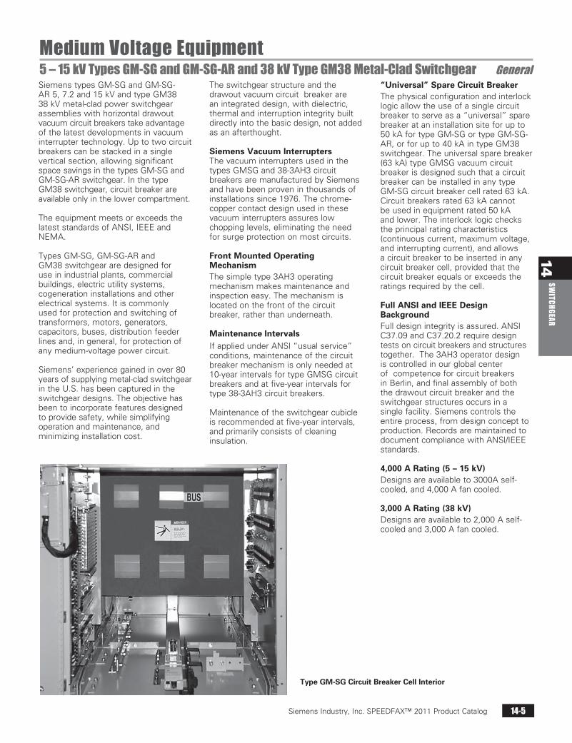
Type GM-SG Circuit Breaker Cell Interior
Siemens Industry, Inc. SPEEDFAX™ 2011 Product Catalog14-6
14SW
ITCH
GEAR
Medium-Voltage Equipment5 – 15 kV Types GM-SG and GM-SG-AR and 38 kV GM38 Metal-Clad Switchgear General
Structural Flexibility for Types GM-SG and GM-SG-ARSiemens metal-clad switchgear provides enhanced flexibility in locating circuit breaker, auxiliary, and metering cells within the structure layout. Circuit breakers rated 1,200 A and 2,000 A may be located in upper or lower cell positions.
Bus sectionalizing (tie) circuit breaker cells may be located on the upper or lower levels and are located next to an auxiliary cell on the same level for the transition bus work.
The types GM-SG and GMSG-AR offer significant flexibility for stacking breakers. See page 14-12 for more information. The 3,000 A circuit breaker can be used for 4,000 A continuous current applications, with the addition of fan cooling equipment in the auxiliary cell above or below the circuit breaker. This application of fan cooling is well suited if loads above 3,000 A are infrequent, as for example, in the case of a fan-cooled rating on a power transformer.
The type GM-SG-AR arc-resistant design offers significant flexibility compared to the design of other suppliers. The side-mounted, arc duct design for the type GM-SG-AR allows the same flexibility as the type GM-SG non-arc resistant design for mounting voltage transformers, a drawout control power transformer and fuse roll-out trays.
Siemens type GM38 metal-clad switchgear provides enhanced flexibility in locating circuit breaker, auxiliary and metering cells within the structure layout. Circuit breakers are located in the lower cell positions. The upper cell position can be used for voltage transformers with the associated drawout primary fuses.
Each vertical section contains the main bus bar compartment, plus a rear compartment for incoming and outgoing connections. The front portion of the vertical section contains a lower cell for circuit breaker, auxiliary devices, VTs, CPT (if primary fuses are located in upper cell) or drawout primary fuses for a CPT located in the rear of the section.
Instruments, protective relays and power meters along with their secondary wiring and other components are located in the upper cell. The switchgear is normally designed so that additional vertical sections may be added in the future.
Enclosure DesignThe switchgear designs includes full ANSI/IEEE C37.20.2 Metal-Clad construction. This means complete enclosure of all live parts and separation of major portions of the circuit to retard the spread of faults to other compartments.
The type GM-SG-AR design includes full ANSI/IEEE C37.20.7-2007, accessibility type 2B. The ground bus extends the entire length of the complete switchgear lineup, and to all circuit breaker cells.
Exhaust System for Type GM-SG-ARThe top-mounted pressure relief channel (PRC) factory-installed for reduced installation time. An outlet of the switchgear room is supplied with each lineup of equipment.
Circuit Breaker InterchangeabilityThe switchgear cubicle and the removable circuit breaker element are both built to master fixtures so circuit breakers of the same ratings are interchangeable with each other even if the circuit breaker is required for use with a cell with “provisions only” supplied years earlier. A circuit breaker of higher rating can be used in a cell of equal or lower rating. The GMSG circuit breaker is not interchangeable with the older designs. 63 kA rated type GMSG circuit breakers can only be used in 63 kA rated cells and lower rated circuit breakers cannot be used in 63 kA rated cells. The type 38-3AH3 circuit breaker is interchangeable with the type 38-3AF circuit breaker, provided the ratings are equal. The type 38-3AF circuit breaker is not interchangeable with the 40 kA type 38-3AH3.
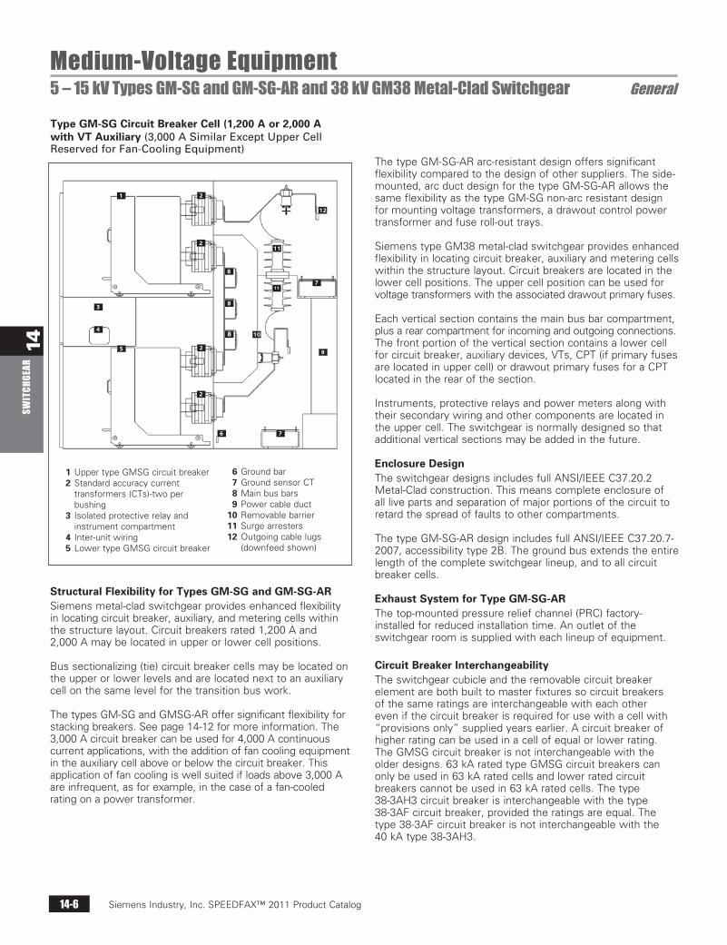
Type GM-SG Circuit Breaker Cell (1,200 A or 2,000 A with VT Auxiliary (3,000ASimilarExceptUpperCellReservedforFan-CoolingEquipment)
1 Upper type GMSG circuit breaker 2 Standard accuracy current
transformers (CTs)-two per bushing
3 Isolated protective relay and instrument compartment
4 Inter-unit wiring 5 Lower type GMSG circuit breaker
6 Ground bar 7 Ground sensor CT 8 Main bus bars 9 Power cable duct 10 Removable barrier 11 Surge arresters 12 Outgoing cable lugs
(downfeed shown)
2
2
1
3
4
5 2
2
6 7
8
8
8
9
10
711
11
12
Siemens Industry, Inc. SPEEDFAX™ 2011 Product Catalog 14-7
14SW
ITCHGEAR
Medium-Voltage EquipmentMedium-Voltage Type GM-SG Switchgear General
n One-high or two-high constructionn Up to 100 full-fault interruptionsn Universal spare circuit breaker for
50 kA and lower ratingsn Universal spare circuit breaker for
63 kA ratingsn Interlocks permit insertion of high
rating vacuum circuit breaker into lower rated cell but not vice versa
n Front accessible circuit breaker operating mechanism for ease of maintenance
n Closed door rackingn Floor rollout circuit breaker in lower
cell without a dollyn Visible secondary disconnectn Circuit breaker ships inside of cell,
thus reducing installation cost and transit damage
n Pair with Siemens protective relays to match any typical application
n Horizontal drawout type GMSG vacuum circuit breaker with type 3AH3 operating mechanism
n Uses the latest developments in vacuum interrupter technology
n Highly reliable vacuum interrupters - MTTF over 42,000 years
n Common type 3AH3 operator platform for all ratings
n Over 60,000 type 3AH3 operators produced since 1998
n Generator circuit breakers (to IEEE C37.013 optionally available)
n 10,000 operations to overhauln Three-cycle interrupting time
(optional)n Meets or exceeds the latest ANSI,
IEEE and NEMA standardsn UL or C-UL Listing available
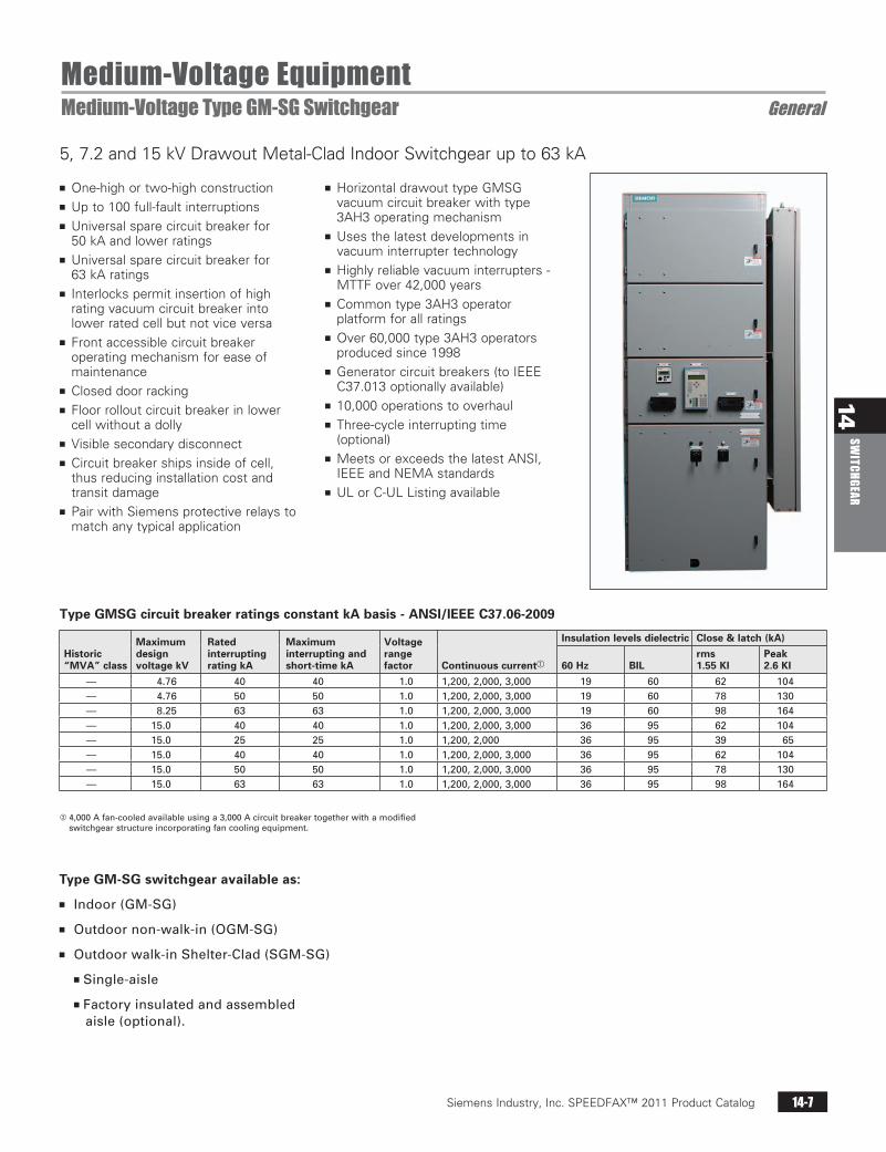
5, 7.2 and 15 kV Drawout Metal-Clad Indoor Switchgear up to 63 kA
Type GMSG circuit breaker ratings constant kA basis - ANSI/IEEE C37.06-2009
Historic “MVA” class
Maximum design voltage kV
Rated interrupting rating kA
Maximum interrupting and short-time kA
Voltage range factor Continuous current
Insulation levels dielectric Close & latch (kA)
60 Hz BILrms 1.55 KI
Peak 2.6 KI
— 4.76 40 40 1.0 1,200,2,000,3,000 19 60 62 104— 4.76 50 50 1.0 1,200,2,000,3,000 19 60 78 130— 8.25 63 63 1.0 1,200,2,000,3,000 19 60 98 164— 15.0 40 40 1.0 1,200,2,000,3,000 36 95 62 104— 15.0 25 25 1.0 1,200,2,000 36 95 39 65— 15.0 40 40 1.0 1,200,2,000,3,000 36 95 62 104— 15.0 50 50 1.0 1,200,2,000,3,000 36 95 78 130— 15.0 63 63 1.0 1,200,2,000,3,000 36 95 98 164
Type GM-SG switchgear available as:
n Indoor(GM-SG)
n Outdoornon-walk-in(OGM-SG)
n Outdoorwalk-inShelter-Clad(SGM-SG)
nSingle-aisle
nFactoryinsulatedandassembledaisle(optional).
4,000Afan-cooledavailableusinga3,000Acircuitbreakertogetherwithamodifiedswitchgearstructureincorporatingfancoolingequipment.
Siemens Industry, Inc. SPEEDFAX™ 2011 Product Catalog14-8
14SW
ITCH
GEAR
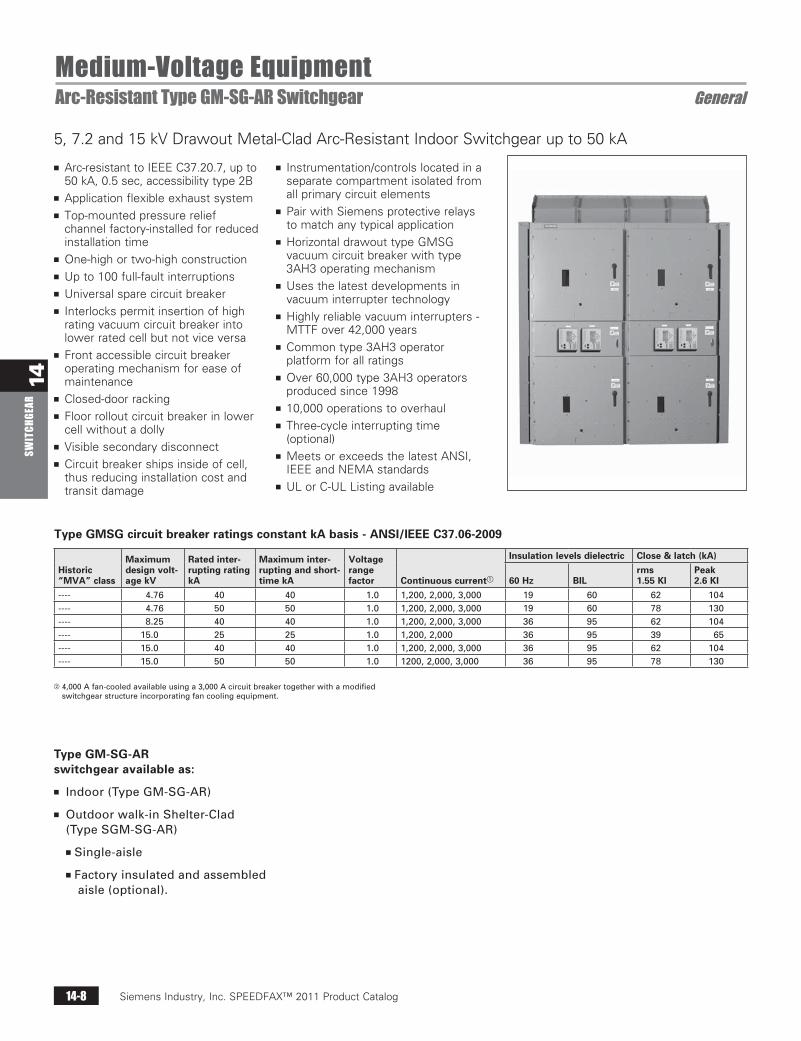
n Arc-resistant to IEEE C37.20.7, up to 50 kA, 0.5 sec, accessibility type 2B
n Application flexible exhaust systemn Top-mounted pressure relief
channel factory-installed for reduced installation time
n One-high or two-high constructionn Up to 100 full-fault interruptionsn Universal spare circuit breakern Interlocks permit insertion of high
rating vacuum circuit breaker into lower rated cell but not vice versa
n Front accessible circuit breaker operating mechanism for ease of maintenance
n Closed-door rackingn Floor rollout circuit breaker in lower
cell without a dollyn Visible secondary disconnectn Circuit breaker ships inside of cell,
thus reducing installation cost and transit damage
n Instrumentation/controls located in a separate compartment isolated from all primary circuit elements
n Pair with Siemens protective relays to match any typical application
n Horizontal drawout type GMSG vacuum circuit breaker with type 3AH3 operating mechanism
n Uses the latest developments in vacuum interrupter technology
n Highly reliable vacuum interrupters - MTTF over 42,000 years
n Common type 3AH3 operator platform for all ratings
n Over 60,000 type 3AH3 operators produced since 1998
n 10,000 operations to overhauln Three-cycle interrupting time
(optional)n Meets or exceeds the latest ANSI,
IEEE and NEMA standardsn UL or C-UL Listing available
Type GM-SG-AR switchgear available as:
n Indoor(TypeGM-SG-AR)
n Outdoorwalk-inShelter-Clad(TypeSGM-SG-AR)
nSingle-aisle
nFactoryinsulatedandassembled aisle(optional).
Medium-Voltage EquipmentArc-Resistant Type GM-SG-AR Switchgear General
Type GMSG circuit breaker ratings constant kA basis - ANSI/IEEE C37.06-2009
Historic “MVA” class
Maximum design volt-age kV
Rated inter-rupting rating kA
Maximum inter-rupting and short-time kA
Voltage range factor Continuous current
Insulation levels dielectric Close & latch (kA)
60 Hz BILrms 1.55 KI
Peak 2.6 KI
---- 4.76 40 40 1.0 1,200,2,000,3,000 19 60 62 104---- 4.76 50 50 1.0 1,200,2,000,3,000 19 60 78 130---- 8.25 40 40 1.0 1,200,2,000,3,000 36 95 62 104---- 15.0 25 25 1.0 1,200,2,000 36 95 39 65---- 15.0 40 40 1.0 1,200,2,000,3,000 36 95 62 104---- 15.0 50 50 1.0 1200,2,000,3,000 36 95 78 130
5, 7.2 and 15 kV Drawout Metal-Clad Arc-Resistant Indoor Switchgear up to 50 kA
Siemens / Speedfax Previous folio: from E50001-F710-A142-V1-4A00 SS 02/10/11
4,000Afan-cooledavailableusinga3,000Acircuitbreakertogetherwithamodifiedswitchgearstructureincorporatingfancoolingequipment.
Siemens Industry, Inc. SPEEDFAX™ 2011 Product Catalog 14-9
14SW
ITCHGEAR
Siemens / Speedfax Previous folio: 13-5 SS 02/08/11
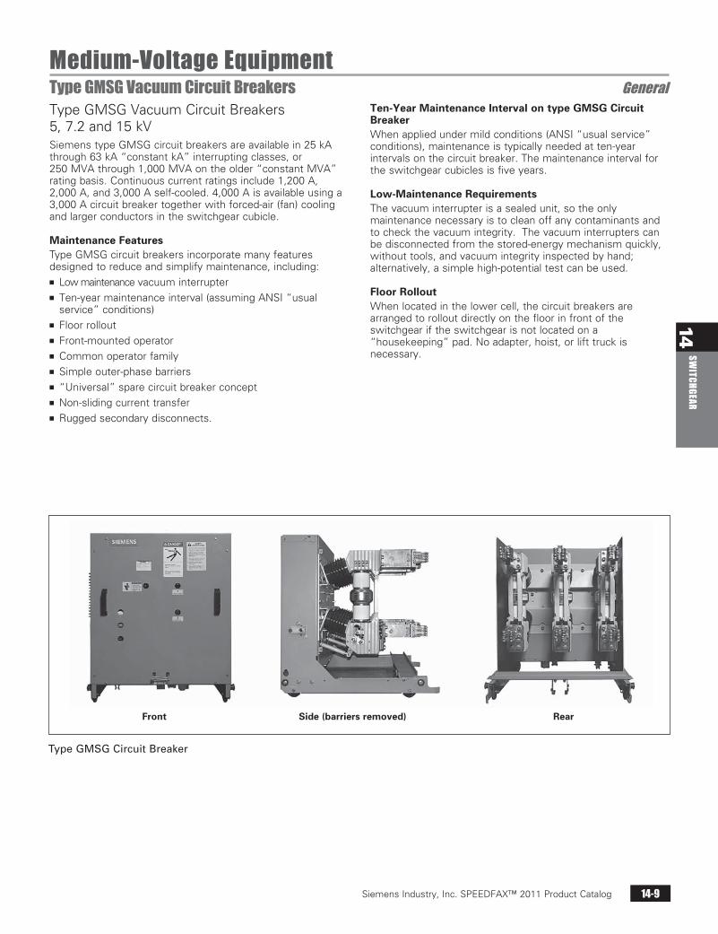
Medium-Voltage EquipmentType GMSG Vacuum Circuit Breakers GeneralType GMSG Vacuum Circuit Breakers 5, 7.2 and 15 kVSiemens type GMSG circuit breakers are available in 25 kA through 63 kA “constant kA” interrupting classes, or 250 MVA through 1,000 MVA on the older “constant MVA” rating basis. Continuous current ratings include 1,200 A, 2,000 A, and 3,000 A self-cooled. 4,000 A is available using a 3,000 A circuit breaker together with forced-air (fan) cooling and larger conductors in the switchgear cubicle.
Maintenance FeaturesType GMSG circuit breakers incorporate many features designed to reduce and simplify maintenance, including:n Low maintenance vacuum interruptern Ten-year maintenance interval (assuming ANSI “usual
service” conditions)n Floor rolloutn Front-mounted operatorn Common operator familyn Simple outer-phase barriersn “Universal” spare circuit breaker conceptn Non-sliding current transfern Rugged secondary disconnects.
TypeGMSGCircuitBreaker
Front Side (barriers removed) Rear
Ten-Year Maintenance Interval on type GMSG Circuit BreakerWhen applied under mild conditions (ANSI “usual service” conditions), maintenance is typically needed at ten-year intervals on the circuit breaker. The maintenance interval for the switchgear cubicles is five years.
Low-Maintenance RequirementsThe vacuum interrupter is a sealed unit, so the only maintenance necessary is to clean off any contaminants and to check the vacuum integrity. The vacuum interrupters can be disconnected from the stored-energy mechanism quickly, without tools, and vacuum integrity inspected by hand; alternatively, a simple high-potential test can be used.
Floor RolloutWhen located in the lower cell, the circuit breakers are arranged to rollout directly on the floor in front of the switchgear if the switchgear is not located on a “housekeeping” pad. No adapter, hoist, or lift truck is necessary.
Siemens Industry, Inc. SPEEDFAX™ 2011 Product Catalog14-10
14SW
ITCH
GEAR
Siemens / Speedfax Previous folio: 13-6 SS 02/08/11
Medium-Voltage EquipmentType GMSG Vacuum Circuit Breaker Ratings Selection
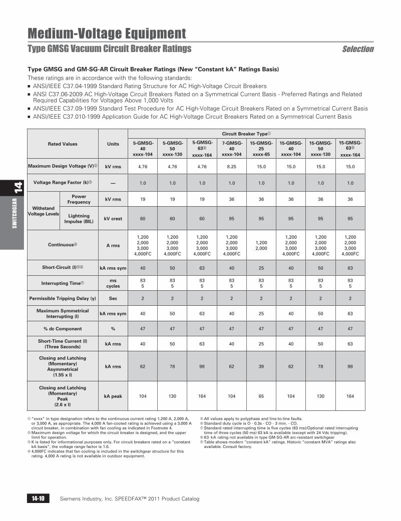
Type GMSG and GM-SG-AR Circuit Breaker Ratings (New “Constant kA” Ratings Basis)These ratings are in accordance with the following standards:n ANSI/IEEE C37.04-1999 Standard Rating Structure for AC High-Voltage Circuit Breakers n ANSI C37.06-2009 AC High-Voltage Circuit Breakers Rated on a Symmetrical Current Basis - Preferred Ratings and Related
Required Capabilities for Voltages Above 1,000 Voltsn ANSI/IEEE C37.09-1999 Standard Test Procedure for AC High-Voltage Circuit Breakers Rated on a Symmetrical Current Basisn ANSI/IEEE C37.010-1999 Application Guide for AC High-Voltage Circuit Breakers Rated on a Symmetrical Current Basis
“xxxx”intypedesignationreferstothecontinuouscurrentrating1,200A,2,000A,or3,000A,asappropriate.The4,000Afan-cooledratingisachievedusinga3,000Acircuitbreaker,incombinationwithfancoolingasindicatedinFootnote4.
Maximumdesignvoltageforwhichthecircuitbreakerisdesigned,andtheupperlimitforoperation.
Kislistedforinformationalpurposesonly.Forcircuitbreakersratedona“constantkAbasis”,thevoltagerangefactoris1.0.
4,000FCindicatesthatfancoolingisincludedintheswitchgearstructureforthisrating.4,000Aratingisnotavailableinoutdoorequipment.
Allvaluesapplytopolyphaseandline-to-linefaults. StandarddutycycleisO-0.3s-CO-3min.-CO.g Standardratedinterruptingtimeisfivecycles(83ms)/Optionalratedinterrupting
timeofthreecycles(50ms)63kAisavailable(exceptwith24Vdctripping).h 63kAratingnotavailableintypeGM-SG-ARarc-resistantswitchgeari Tableshowsmodern“constantkA”ratings.Historic“constantMVA”ratingsalso
available.Consultfactory.
Rated Values Units
Circuit Breaker Type
5-GMSG-40
xxxx-104
5-GMSG-50
xxxx-130
5-GMSG-63h
xxxx-164
7-GMSG-40
xxxx-104
15-GMSG-25
xxxx-65
15-GMSG-40
xxxx-104
15-GMSG-50
xxxx-130
15-GMSG-63h
xxxx-164
Maximum Design Voltage (V) kV rms 4.76 4.76 4.76 8.25 15.0 15.0 15.0 15.0
Voltage Range Factor (k) — 1.0 1.0 1.0 1.0 1.0 1.0 1.0 1.0
Withstand Voltage Levels
Power Frequency kV rms 19 19 19 36 36 36 36 36
Lightning Impulse (BIL) kV crest 60 60 60 95 95 95 95 95
Continuous A rms
1,2002,0003,000
4,000FC
1,2002,0003,000
4,000FC
1,2002,0003,000
4,000FC
1,2002,0003,000
4,000FC
1,2002,000
1,2002,0003,000
4,000FC
1,2002,0003,000
4,000FC
1,2002,0003,000
4,000FC
Short-Circuit (I) kA rms sym 40 50 63 40 25 40 50 63
Interrupting Timeg mscycles
835
835
835
835
835
835
835
835
Permissible Tripping Delay (y) Sec 2 2 2 2 2 2 2 2
Maximum Symmetrical Interrupting (I) kA rms sym 40 50 63 40 25 40 50 63
% dc Component % 47 47 47 47 47 47 47 47
Short-Time Current (I) (Three Seconds) kA rms 40 50 63 40 25 40 50 63
Closing and Latching (Momentary) Asymmetrical
(1.55 x I)
kA rms 62 78 98 62 39 62 78 98
Closing and Latching (Momentary)
Peak (2.6 x I)
kA peak 104 130 164 104 65 104 130 164
Siemens Industry, Inc. SPEEDFAX™ 2011 Product Catalog 14-11
14SW
ITCHGEAR
Siemens / Speedfax Previous folio: 13-8 SS 02/08/11
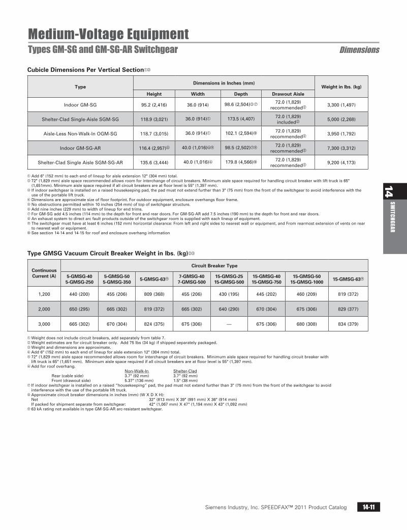
Medium-Voltage EquipmentTypes GM-SG and GM-SG-AR Switchgear Dimensions
TypeDimensions in Inches (mm)
Weight in lbs. (kg)Height Width Depth Drawout Aisle
IndoorGM-SG 95.2(2,416) 36.0(914) 98.6(2,504) g 72.0(1,829)recommended 3,300(1,497)
Shelter-CladSingle-AisleSGM-SG 118.9(3,021) 36.0(914) 173.5(4,407) 72.0(1,829)included 5,000(2,268)
Aisle-LessNon-Walk-InOGM-SG 118.7(3,015) 36.0(914) 102.1(2,594) 72.0(1,829)recommended 3,950(1,792)
IndoorGM-SG-AR 116.4(2,957) 40.0(1,016)i 98.5(2,502)gi 72.0(1,829)recommended 7,300(3,312)
Shelter-CladSingleAisleSGM-SG-AR 135.6(3,444) 40.0(1,016) 179.8(4,566) 72.0(1,829)recommended 9,200(4,173)
Continuous Current (A)
Circuit Breaker Type
5-GMSG-405-GMSG-250
5-GMSG-505-GMSG-350 5-GMSG-63i 7-GMSG-40
7-GMSG-50015-GMSG-2515-GMSG-500
15-GMSG-4015-GMSG-750
15-GMSG-5015-GMSG-1000 15-GMSG-63i
1,200 440(200) 455(206) 809(368) 455(206) 430(195) 445(202) 460(209) 819(372)
2,000 650(295) 665(302) 819(372) 665(302) 640(290) 670(304) 675(306) 829(377)
3,000 665(302) 670(304) 824(375) 675(306) — 675(306) 680(308) 834(379)
Weightdoesnotincludecircuitbreakers,addseparatelyfromtable7. Weightestimatesareforcircuitbreakeronly.Add75lbs(34kg)ifshippedseparatelypackaged. Weightanddimensionsareapproximate. Add6"(152mm)toeachendoflineupforaisleextension12"(304mm)total. 72"(1,829mm)aislespacerecommendedallowsroomforinterchangeofcircuitbreakers.Minimumaislespacerequiredforhandlingcircuitbreakerwith
lifttruckis65"(1,651mm).Minimumaislespacerequiredifallcircuitbreakersareatfloorlevelis55"(1,397mm). Addforroofoverhang. Non-Walk-In Shelter-Clad
Rear(cableside) 3.7"(92mm) 3.7"(92mm) Front(drawoutside) 5.37"(136mm) 1.5"(38mm)
g Ifindoorswitchgearisinstalledonaraised“housekeeping”pad,thepadmustnotextendfurtherthan3"(75mm)fromthefrontoftheswitchgeartoavoidinterferencewiththeuseoftheportablelifttruck.
h Approximatecircuitbreakerdimensionsininches(mm)(WXDXH):Net 32"(813mm)X39"(991mm)X36"(914mm)Ifpackedforshipmentseparatefromswitchgear: 42"(1,067mm)X47"(1,194mm)X43"(1,092mm)
i 63kAratingnotavailableintypeGM-SG-ARarc-resistantswitchgear.
Type GMSG Vacuum Circuit Breaker Weight in lbs. (kg)
Cubicle Dimensions Per Vertical Section
Add6"(152mm)toeachendoflineupforaisleextension12"(304mm)total.72"(1,829mm)aislespacerecommendedallowsroomforinterchangeofcircuitbreakers.Minimumaislespacerequiredforhandlingcircuitbreakerwithlifttruckis65"
(1,651mm).Minimumaislespacerequiredifallcircuitbreakersareatfloorlevelis55"(1,397mm).Ifindoorswitchgearisinstalledonaraisedhousekeepingpad,thepadmustnotextendfurtherthan3"(75mm)fromthefrontoftheswitchgeartoavoidinterferencewiththe
useoftheportablelifttruck.Dimensionsareapproximatesizeoffloorfootprint.Foroutdoorequipment,enclosureoverhangsfloorframe.Noobstructionspermittedwithin10inches(254mm)oftopofswitchgearstructure.Addnineinches(229mm)towidthoflineupforendtrims.gForGM-SGadd4.5inches(114mm)tothedepthforfrontandreardoors.ForGM-SG-ARadd7.5inches(190mm)tothedepthforfrontandreardoors.hAnexhaustsystemtodirectarcfaultproductsoutsideoftheswitchgearroomissuppliedwitheachlineupofequipment.iTheswitchgearmusthaveatleast6inches(152mm)horizontalclearance:Fromleftandrightsidestonearestwallorequipment,andFromrearmostextensionofventsonrear
tonearestwallorequipment.Seesection14-14and14-15forroofandenclosureoverhanginformation

Siemens Industry, Inc. SPEEDFAX™ 2011 Product Catalog14-12
14SW
ITCH
GEAR
Siemens / Speedfax Previous folio: 13-9 SS 02/08/11
Medium-Voltage EquipmentTypes GM-SG and GM-SG-AR Stacking Versatility Dimensions
Mainbussizes1,200A,2,000A,3,000Aor4,000A(self-cooled). Norolloutauxiliariesallowedinuppercell(CorD)iflowercell(B)has
3,000Acircuitbreaker.If3,000Acircuitbreakerislocatedinuppercell(A),onerolloutauxiliarymaybelocatedinlowercell(F).
Auxiliarycells(C,D,E,orF)mayeachcontainonerollout(exceptasindicatedinFootnotes2and5).
Fuserolloutforstationarycontrolpowertransformer(CPT)mustbelocatedinlowerrolloutcellF,ifCPTislocatedinrearorisremote.IfCPTislocatedinlowerauxiliarycell(EandF),fuserolloutislocatedinupperauxiliarycell.
Forfan-cooled4,000Arating,circuitbreaker(3,000Aself-cooled,4,000Afan-cooled)maybelocatedinlowercell(B)withfancoolingincellA.
Stackingarrangementsareavailableasshown.Totalcircuitbreakerloadinginaverticalunitmaynotexceedmainbusrating.ConsultSiemensforspecificapplicationassistanceregardingtotalloadlimitsineachunit,orrefertoANSI/IEEEC37.20.2.
TypeGM-SGStackingVersatility
1,200ACircuit
Breaker
Low-VoltagePanel
1,200ACircuit
Breaker
1,200ACircuit
Breaker
Low-VoltagePanel
2,000ACircuitA243
Breaker
2,000ACircuit
Breaker
Low-VoltagePanel
1,200ACircuit
Breaker
1,200ACircuit
Breaker
Low-VoltagePanel
Auxiliary
Auxiliary
1,200ACircuit
Breaker
Low-VoltagePanel
Auxiliary
Auxiliary
Low-VoltagePanel
2,000ACircuit
Breaker
2,000ACircuit
Breaker
Low-VoltagePanel
2,000ACircuit
Breaker
3,000A
CircuitBreaker
Low-VoltagePanel
Low-VoltagePanel
2,000ACircuit
Breaker
Low-VoltagePanel
3,000A
CircuitBreaker
Low-VoltagePanel
Vented
Auxiliary
Auxiliary
Auxiliary
Auxiliary
Auxiliary
Auxiliary
Auxiliary
Auxiliary
Vented
Auxiliary
A A AD
C
A
B F
E
B
D A A D
BB F
E
FB F
E E
C C

Siemens Industry, Inc. SPEEDFAX™ 2011 Product Catalog 14-13
14SW
ITCHGEAR
Siemens / Speedfax Previous folio: 13-10 SS 02/08/11
Medium-Voltage EquipmentTypes GM-SG and GM-SG-AR Accessories GeneralStandard Accessories Include:Small accessories are located in an accessory cabinet, normally mounted on the end of an indoor assembly. The accessory cabinet can be removed and installed on a wall, if desired.n Manual racking crankn Spring charging crankn Drawout extension rails (facilitate handling of circuit
breakers in upper cell)n Lifting sling (for circuit breakers above floor level)n Split plug jumper (standard unless test cabinet is furnished)n Contact lubricantn Touch up paint.
Optional Accessories Include:n Circuit breaker lift devicen Adapter to enable lift truck use for VT, CPT or CPT Fuse rollout trayn Test cabinet (in place of split plug jumper)n Test plugs (if required by devices)n Electric racking motor assembly (to enable racking while
operator is at a distance from the switchgear)n Manual or electrical ground and test device (manual device
not applicable for type GM-SG-AR).
Test provisions, either a split plug jumper or a test cabinet, are available for testing the circuit breaker outside its cubicle.
The split plug jumper is used to bridge the secondary disconnects with a flexible cable, so the circuit breaker may be electrically closed and tripped with the control switch on the instrument panel while the circuit breaker is outside of its compartment. The test cabinet, including a control switch is used for closing and tripping the circuit breaker at a location remote from the switchgear.
Manually Operated Ground and Test Device (up to 50 kA)This is a drawout element that can be inserted into a circuit breaker cell rated for a short-circuit current of 50 kA or lower. It opens the shutters, connects to the cell primary disconnecting contacts and so provides a means to make the primary disconnect stabs available for testing. It is suitable for high-potential testing of outgoing circuits of the switchgear main bus or for phase sequence checking. It also provides a means to connect temporary grounds to de-energized circuits for maintenance purposes.
The manual ground and test incorporates three-position, single-pole switches (upper stabs to ground, neutral, and lower stabs to ground), eliminating the need for user-furnished ground cables. The switches hookstick, in the closed position, operable and are rated for the full momentary and short-time ratings of the associated switchgear. User-furnished grounding cables and commercially available ground clamps seldom have ratings equal to those of the switchgear. AccessoryCabinet
Electrical Ground and Test Device (Up to 63 kA)An electrical ground and test device includes a power operated switch (derived from a type GMSG circuit breaker) arranged to allow grounding one set of disconnect stabs. Two devices, one each for the upper and lower stabs, are required if grounding is desired to either side of the unit. The device also provides a means of access to the primary circuits for high-potential tests or for phase-sequence checking. These devices are able to close and latch against short-circuit currents corresponding to the ratings of the equipment. Due to the unique requirements frequently involved in such devices, all applications of electrically operated ground and test devices should be referred to Siemens for review.
Note: Due to the special nature of ground and test devices, each user must develop definitive operating procedures for incorporating safe operating practices. Only qualified personnel should be allowed to use ground and test devices.
Siemens Industry, Inc. SPEEDFAX™ 2011 Product Catalog14-14
14SW
ITCH
GEAR
110.3 (2,802) to Floor
Line
Rear
of F
ram
e
Fro
nt
of F
ram
e
118.7 (3,015) to Floor
Line
Switchgear BaseFloorLine 102.2
(2,594)
107.0 (2,718)
Siemens / Speedfax Previous folio: 13-11 SS 02/08/11
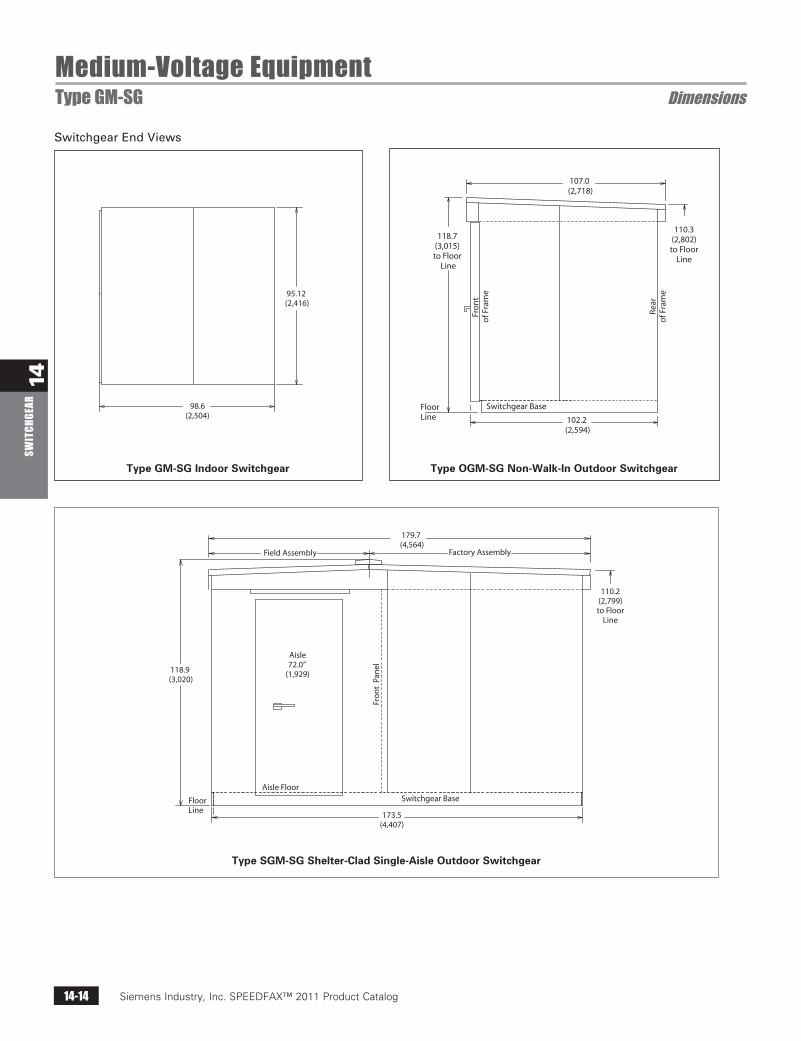
Medium-Voltage EquipmentType GM-SG Dimensions
SwitchgearEndViews
98.6 (2,504)
95.12 (2,416)
179.7 (4,564)
Field Assembly Factory Assembly
118.9 (3,020)
Aisle72.0”
(1,929)
Fro
nt
Pan
el
Switchgear Base
110.2 (2,799) to Floor
Line
FloorLine
Aisle Floor
173.5(4,407)
Type OGM-SG Non-Walk-In Outdoor SwitchgearType GM-SG Indoor Switchgear
Type SGM-SG Shelter-Clad Single-Aisle Outdoor Switchgear
Siemens Industry, Inc. SPEEDFAX™ 2011 Product Catalog 14-15
14SW
ITCHGEAR
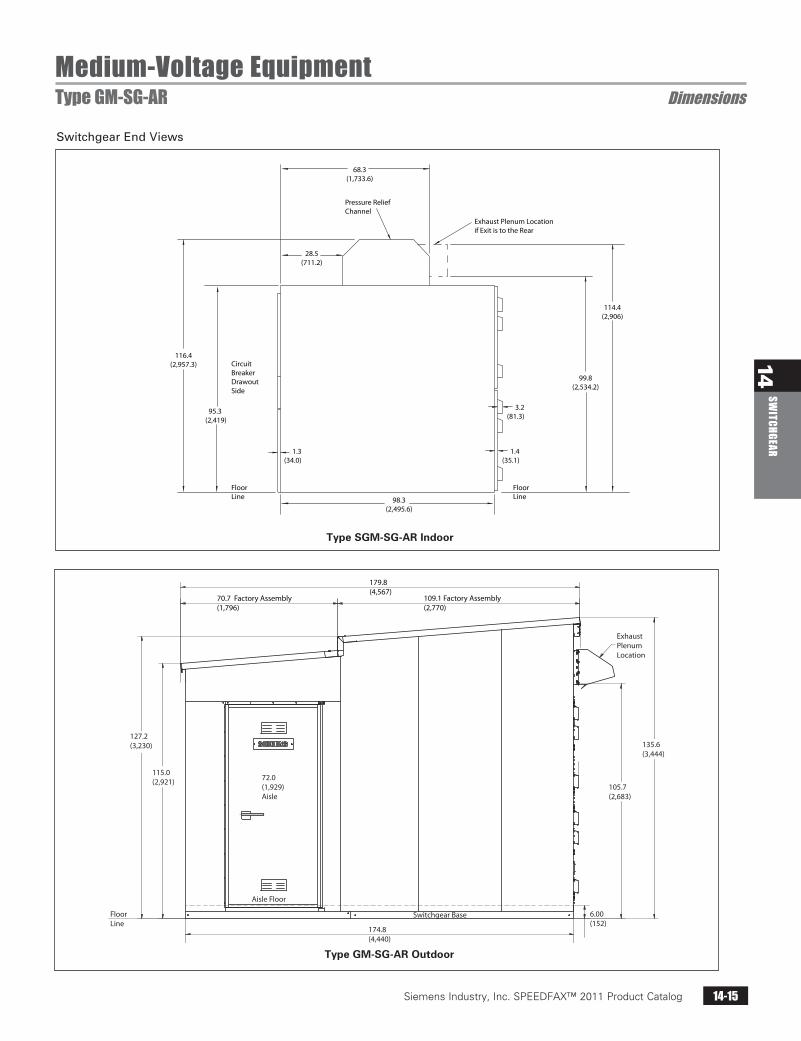
SwitchgearEndViews
Medium-Voltage EquipmentType GM-SG-AR Dimensions
Pressure ReliefChannel
68.3(1,733.6)
28.5(711.2)
116.4(2,957.3)
95.3 (2,419)
98.3(2,495.6)
FloorLine
CircuitBreakerDrawoutSide
FloorLine
1.3(34.0)
1.4(35.1)
3.2(81.3)
99.8(2,534.2)
114.4(2,906)
Exhaust Plenum Locationif Exit is to the Rear
70.7 Factory Assembly(1,796)
109.1 Factory Assembly(2,770)
179.8 (4,567)
Exhaust Plenum Location
135.6 (3,444)
105.7 (2,683)
6.00 (152)
Switchgear Base
174.8(4,440)
72.0 (1,929)Aisle
Aisle Floor
FloorLine
115.0(2,921)
127.2(3,230)
Type GM-SG-AR Outdoor
Type SGM-SG-AR Indoor
Siemens Industry, Inc. SPEEDFAX™ 2011 Product Catalog14-16
14SW
ITCH
GEAR
Siemens / Speedfax Previous folio: 13-12 SS 02/08/11
Medium-Voltage Equipment38 kV Type GM38 Metal-Clad Switchgear General/Specifications
GeneralMeasured Parameter
Nominal Voltage Class
MaxVoltage Range Factor
Low FrequencyImpulse
KE kV RMS
kV Crest
Amperes
I kA RMSInterrupting Time Cycles
Rated Max. Voltage Divided by K
3-Sec. Short TimeCurrent Carrying
E/K kV RMS
K Times RatedShort CircuitCurrent KI
kA RMS
kA RMS
kA RMS
kA Crest
Permissible Tripping Delay Y Sec.
215
2335
35
56
95
2
kV RMS
MVAkV 38.0
150038.0
1.6580
150
Circuit Breaker Type38-3AH-1500 �
38-3AH-31 �
RatedValues
RelatedRequiredCapa-bilities
RatedVoltage
InsulationLevels
RatedCurrent
Current
Closing andLatching(Momentary)�
Rated WithstandTest Voltage
120020003000
31.55
3831.5
31.5
50
85
2
38.0—38.0
1.080
150120020003000
38-3AH-40 �
405
3840
40
62
104
2
38.0—38.0
1.080
150120020003000
Table 8 Type 38-3AH Circuit Breaker Ratings
� Type 38-3AH-1500 ratings are in accord with ANSI C37.06-1987. Type 38-3AH-31 and 38-3AH-40 ratings conform toANSI/IEEE C37.06 2009 ratings.
� Maximum voltage for which the circuit breaker is designed and the upper limit for operation.
� 3000 ampere ratings are achieved using forced air cooling in the switchgear cubicle.
Required Symmetrical Interrupting Capacity = Rated Short Circuit Current ×Rated Maximum Voltage
Operating Voltage
� K is the ratio of rated maximum voltage to the lower limit of the range of operating voltage in which the requiredsymmetrical and asymmetrical interrupting capabilities vary in inverse proportion to the operating voltage.
� To obtain the required symmetrical interrupting capability of a circuit breaker at an operating voltage between 1/K timesrated maximum voltage and rated maximum voltage, the following formula shall be used.
For operating voltages below 1/K times rated maximum voltage, the required symmetrical interrupting capability of thecircuit breaker shall be equal to K times rated short circuit current.
� With the limitations stated in 5.10 of ANSI/IEEE Standard C37.04-1979, all values apply for polyphase and line-to-line faults.For single phase-to-ground faults, the specific conditions stated in 5.10.2.3 of ANSI Standard C37.04-1979 apply.
� Current values in this row are not to be exceeded even for voltages below 1/K times rated maximum voltage.For voltages between rated maximum voltage and 1/K times rated maximum voltage, follow 5 above.
� Current values in this row are independent of operating voltage up to and including rated maximum voltage.� Included for reference only—not listed in ANSI/IEEE C37.06.
Continuous �
Short circuit (at rated max. kV) � �
Max. Sym. Interrupting �
Nominal 3-Phase MVA Class �
FC FC FC
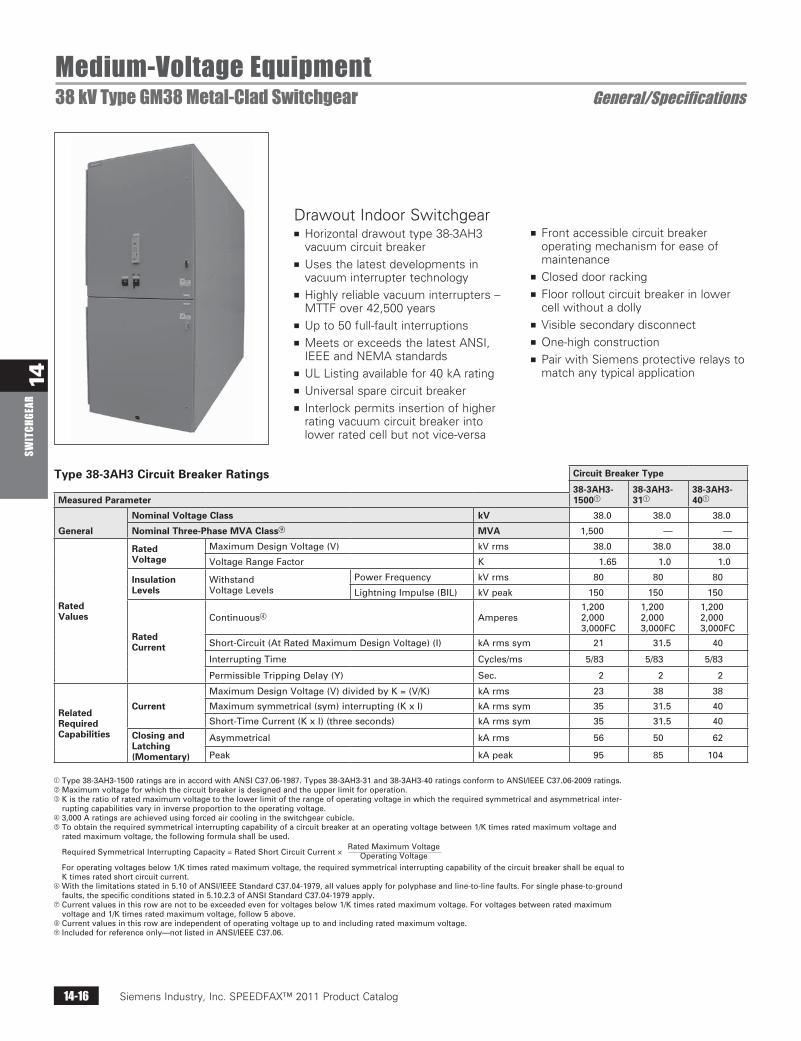
Drawout Indoor Switchgearn Horizontal drawout type 38-3AH3
vacuum circuit breakern Uses the latest developments in
vacuum interrupter technologyn Highly reliable vacuum interrupters –
MTTF over 42,500 yearsn Up to 50 full-fault interruptionsn Meets or exceeds the latest ANSI,
IEEE and NEMA standardsn UL Listing available for 40 kA ratingn Universal spare circuit breakern Interlock permits insertion of higher
rating vacuum circuit breaker into lower rated cell but not vice-versa
n Front accessible circuit breaker operating mechanism for ease of maintenance
n Closed door rackingn Floor rollout circuit breaker in lower
cell without a dollyn Visible secondary disconnectn One-high constructionn Pair with Siemens protective relays to
match any typical application
Type 38-3AH3 Circuit Breaker Ratings Circuit Breaker Type
38-3AH3-1500
38-3AH3-31
38-3AH3-40Measured Parameter
General
Nominal Voltage Class kV 38.0 38.0 38.0
Nominal Three-Phase MVA Classi MVA 1,500 — —
RatedValues
RatedVoltage
MaximumDesignVoltage(V) kVrms 38.0 38.0 38.0
VoltageRangeFactor K 1.65 1.0 1.0
InsulationLevels
WithstandVoltageLevels
PowerFrequency kVrms 80 80 80
LightningImpulse(BIL) kVpeak 150 150 150
RatedCurrent
Continuous Amperes1,2002,0003,000FC
1,2002,0003,000FC
1,2002,0003,000FC
Short-Circuit(AtRatedMaximumDesignVoltage)(I) kArmssym 21 31.5 40
InterruptingTime Cycles/ms 5/83 5/83 5/83
PermissibleTrippingDelay(Y) Sec. 2 2 2
RelatedRequiredCapabilities
Current
MaximumDesignVoltage(V)dividedbyK=(V/K) kArms 23 38 38
Maximumsymmetrical(sym)interrupting(KxI) kArmssym 35 31.5 40
Short-TimeCurrent(KxI)(threeseconds) kArmssym 35 31.5 40
Closing andLatching(Momentary)
Asymmetrical kArms 56 50 62
Peak kApeak 95 85 104
Type38-3AH3-1500ratingsareinaccordwithANSIC37.06-1987.Types38-3AH3-31and38-3AH3-40ratingsconformtoANSI/IEEEC37.06-2009ratings.Maximumvoltageforwhichthecircuitbreakerisdesignedandtheupperlimitforoperation.Kistheratioofratedmaximumvoltagetothelowerlimitoftherangeofoperatingvoltageinwhichtherequiredsymmetricalandasymmetricalinter-
ruptingcapabilitiesvaryininverseproportiontotheoperatingvoltage.3,000Aratingsareachievedusingforcedaircoolingintheswitchgearcubicle.Toobtaintherequiredsymmetricalinterruptingcapabilityofacircuitbreakeratanoperatingvoltagebetween1/Ktimesratedmaximumvoltageand
ratedmaximumvoltage,thefollowingformulashallbeused.
RequiredSymmetricalInterruptingCapacity=RatedShortCircuitCurrent×
Foroperatingvoltagesbelow1/Ktimesratedmaximumvoltage,therequiredsymmetricalinterruptingcapabilityofthecircuitbreakershallbeequaltoKtimesratedshortcircuitcurrent.
Withthelimitationsstatedin5.10ofANSI/IEEEStandardC37.04-1979,allvaluesapplyforpolyphaseandline-to-linefaults.Forsinglephase-to-groundfaults,thespecificconditionsstatedin5.10.2.3ofANSIStandardC37.04-1979apply.
gCurrentvaluesinthisrowarenottobeexceededevenforvoltagesbelow1/Ktimesratedmaximumvoltage.Forvoltagesbetweenratedmaximumvoltageand1/Ktimesratedmaximumvoltage,follow5above.
hCurrentvaluesinthisrowareindependentofoperatingvoltageuptoandincludingratedmaximumvoltage.iIncludedforreferenceonly—notlistedinANSI/IEEEC37.06.
RatedMaximumVoltageOperatingVoltage
Siemens Industry, Inc. SPEEDFAX™ 2011 Product Catalog 14-17
14SW
ITCHGEAR
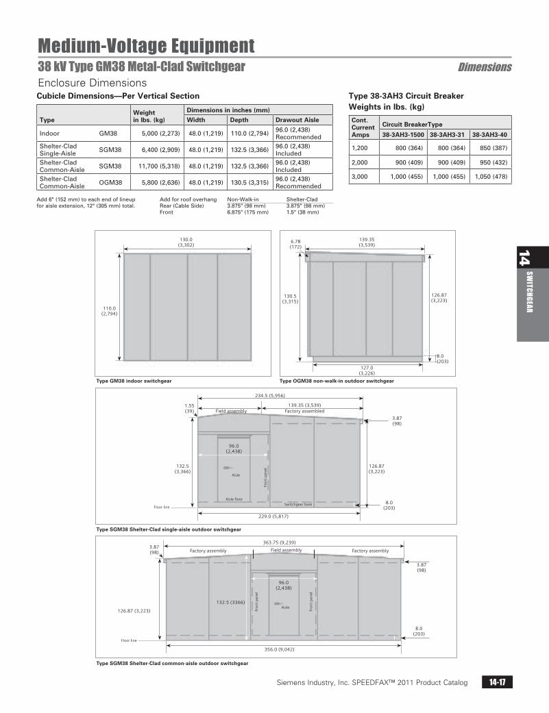
Type GM38 indoor switchgear
Type SGM38 Shelter-Clad single-aisle outdoor switchgear
Type SGM38 Shelter-Clad common-aisle outdoor switchgear
Type OGM38 non-walk-in outdoor switchgear
110.0 (2,794)
132.5(3,366)
126.87(3,223)
3.87(98)
8.0(203)
3.87(98)
8.0(203)
96.0(2,438)
Aisle floor
Aisle
Aisle
Floor line
Floor line
Fro
nt
pan
el
Fro
nt
pan
el
Fro
nt
pan
el
Switchgear base
130.0(3,302)
234.5 (5,956)
1.55(39)
3.87(98)
6.78(172)
229.0 (5,817)
363.75 (9,239)
96.0 (2,438)
356.0 (9,042)
126.87 (3,223)
132.5 (3366)
139.35 (3,539)Factory assembledField assembly
Factory assembly Factory assemblyField assembly
139.35(3,539)
130.5(3,315)
127.0(3,226)
126.87(3,223)
8.0(203)
Siemens / Speedfax Previous folio: 13-13 Updated SS 02/08/11
Medium-Voltage Equipment38 kV Type GM38 Metal-Clad Switchgear DimensionsEnclosure DimensionsCubicle Dimensions—Per Vertical Section
TypeWeightin lbs. (kg)
Dimensions in inches (mm)
Width Depth Drawout Aisle
Indoor GM38 5,000(2,273) 48.0(1,219) 110.0(2,794) 96.0(2,438)Recommended
Shelter-CladSingle-Aisle SGM38 6,400(2,909) 48.0(1,219) 132.5(3,366) 96.0(2,438)
IncludedShelter-CladCommon-Aisle SGM38 11,700(5,318) 48.0(1,219) 132.5(3,366) 96.0(2,438)
IncludedShelter-CladCommon-Aisle OGM38 5,800(2,636) 48.0(1,219) 130.5(3,315) 96.0(2,438)
Recommended
Add6"(152mm)toeachendoflineupforaisleextension,12"(305mm)total.
Addforroofoverhang Non-Walk-in Shelter-CladRear(CableSide) 3.875"(98mm) 3.875"(98mm)Front 6.875"(175mm) 1.5"(38mm)
Type 38-3AH3 Circuit Breaker Weights in lbs. (kg)
Cont.CurrentAmps
Circuit BreakerType
38-3AH3-1500 38-3AH3-31 38-3AH3-40
1,200 800(364) 800(364) 850(387)
2,000 900(409) 900(409) 950(432)
3,000 1,000(455) 1,000(455) 1,050(478)
Siemens Industry, Inc. SPEEDFAX™ 2011 Product Catalog14-18
14SW
ITCH
GEAR
Siemens / Speedfax Previous folio: 13-15 NO Edits rev2
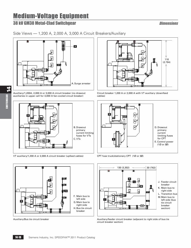
Medium-Voltage Equipment38 kV GM38 Metal-Clad Switchgear Dimensions
Side Views — 1,200 A, 2,000 A, 3,000 A Circuit Breakers/Auxiliary
Auxiliary/1,200A, 2,000 A or 3,000 A circuit breaker (no drawout auxiliaries in upper cell for 3,000 A fan-cooled circuit breaker)
VT auxiliary/1,200 A or 2,000 A circuit breaker (upfeed cables)
Auxiliary/Bus tie circuit breaker
Circuit breaker 1,200 A or 2,000 A with VT auxiliary (downfeed cables)
CPT fuse truck/stationary CPT (1Ø or 3Ø)
Auxiliary/feeder circuit breaker (adjacent to right side of bus tie circuit breaker section)
A
BD
E
F
G
HJ
K
L
M
C
A. Surge arrester
B. Drawout primary current limiting fuses for VTs
C. VTs
F. Main bus to left side
G. Main bus to right side
H. Bus tie circuit breaker
D. Drawout primary current limiting fuses for CPT
E. Control power (1Ø or 3Ø)
J. Feeder circuit breaker
K. Main bus to right side
L. Transition busM. Main bus to
left side (bus tie circuit breaker section)
110(2.794)
130 (3,302) 30 (762)
Siemens Industry, Inc. SPEEDFAX™ 2011 Product Catalog 14-19
14SW
ITCHGEAR
Siemens / Speedfax Previous folio: 13-16
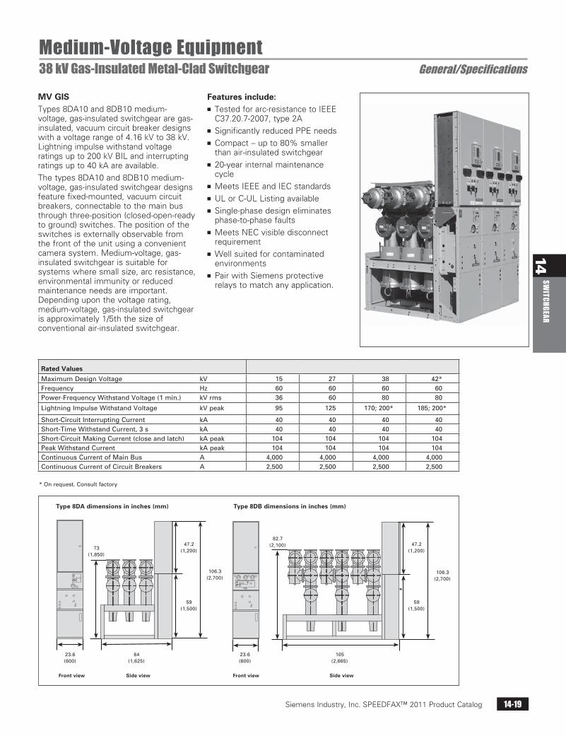
Medium-Voltage Equipment38 kV Gas-Insulated Metal-Clad Switchgear General/Specifications
MV GISTypes 8DA10 and 8DB10 medium-voltage, gas-insulated switchgear are gas-insulated, vacuum circuit breaker designs with a voltage range of 4.16 kV to 38 kV. Lightning impulse withstand voltage ratings up to 200 kV BIL and interrupting ratings up to 40 kA are available.
The types 8DA10 and 8DB10 medium-voltage, gas-insulated switchgear designs feature fixed-mounted, vacuum circuit breakers, connectable to the main bus through three-position (closed-open-ready to ground) switches. The position of the switches is externally observable from the front of the unit using a convenient camera system. Medium-voltage, gas-insulated switchgear is suitable for systems where small size, arc resistance, environmental immunity or reduced maintenance needs are important. Depending upon the voltage rating, medium-voltage, gas-insulated switchgear is approximately 1/5th the size of conventional air-insulated switchgear.
*Onrequest.Consultfactory
Front view Front viewSide view Side view
23.6 (600)
Type 8DB dimensions in inches (mm)Type 8DA dimensions in inches (mm)
73 (1,850)
64 (1,625)
23.6 (600)
82.7 (2,100)
105 (2,665)
59 (1,500)
47.2 (1,200)
106.3 (2,700)
59 (1,500)
47.2 (1,200)
106.3 (2,700)
Features include:n Tested for arc-resistance to IEEE
C37.20.7-2007, type 2An Significantly reduced PPE needsn Compact – up to 80% smaller
than air-insulated switchgearn 20-year internal maintenance
cyclen Meets IEEE and IEC standardsn UL or C-UL Listing availablen Single-phase design eliminates
phase-to-phase faultsn Meets NEC visible disconnect
requirementn Well suited for contaminated
environmentsn Pair with Siemens protective
relays to match any application.
Rated Values
MaximumDesignVoltage kV 15 27 38 42*Frequency Hz 60 60 60 60Power-FrequencyWithstandVoltage(1min.) kVrms 36 60 80 80
LightningImpulseWithstandVoltage kVpeak 95 125 170;200* 185;200*
Short-CircuitInterruptingCurrent kA 40 40 40 40Short-TimeWithstandCurrent,3s kA 40 40 40 40Short-CircuitMakingCurrent(closeandlatch) kApeak 104 104 104 104PeakWithstandCurrent kApeak 104 104 104 104ContinuousCurrentofMainBus A 4,000 4,000 4,000 4,000ContinuousCurrentofCircuitBreakers A 2,500 2,500 2,500 2,500
Siemens Industry, Inc. SPEEDFAX™ 2011 Product Catalog14-20
14SW
ITCH
GEAR
Siemens / Speedfax Previous folio: 13-17
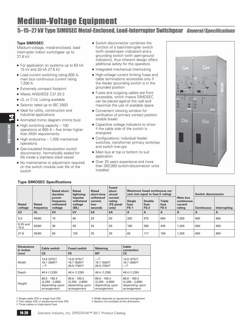
Medium-Voltage Equipment5–15–27 kV Type SIMOSEC Metal-Enclosed, Load-Interrupter Switchgear General/Specifications
Type SIMOSECMedium-voltage, metal-enclosed, load-interrupter indoor switchgear up to 27.6 kV.
n For application on systems up to 63 kA 15 kV and 20 kA 27.6 kV
n Load current switching rating 600 A, main bus continuous current rating 1,200 A
n Extremely compact footprintn Meets ANSI/IEEE C37.20.3n UL or C-UL Listing availablen Seismic rated up to IBC 2003n Ideal for utility, construction and
industrial applicationsn Animated mimic diagram (mimic bus)n High switching capacity – 100
operations at 600 A – five times higher than ANSI requirements
n High endurance – 1,000 mechanical operations
n Gas-insulated three-position switch disconnector, hermetically sealed for life inside a stainless steel vessel
n No maintenance or adjustment required on the switch module over life of the switch
n Switch disconnector combines the function of a load-interrupter switch (with closed-open indication) and a grounding switch (with open-ground indication), thus inherent design offers additional safety for the operators
n Integrated mechanical interlockingn High-voltage current limiting fuses and
cable terminations accessible only if the feeder grounding switch is in the grounded position
n Fuses and outgoing cables are front accessible, which means SIMOSEC can be placed against the wall and maximize the use of available space
n Convenient viewing window for verification of primary contact position (visible break)
n Capacitive voltage indicators to show if the cable side of the switch is energized
n Configurations: individual feeder switches, transformer primary switches and switch line-ups
n Main bus at top or bottom to suit application
n Over 20 years experience and more than 350,000 switch-disconnector units installed
Type SIMOSEC Specifications
Ratedvoltage
Ratedfrequency
Rated short- durationpower-frequencywithstandvoltage
Ratedlightning- impulsewithstandvoltage(BIL)
Ratedshort-timewithstandcurrent,twoseconds
Fusedshort-circuitcurrentrating(FS panelonly)
Maximum fused continuous cur-rent (not equal to fuse E rating)
Main buscontinuouscurrentrating
Switch disconnector
SinglefuseFS-1
DoublefuseFS-2
TriplefuseFS-3 Continuous Interrupting
kV Hz kV kV kA kA A A A A A A
5.0 50/60 19 60 25 63 325 575 600 1,200 600 600
8.25and15.0 50/60 36 95 25 63 165 305 430 1,200 600 600
27.6 50/60 60 125 20 20 65 117 156 1,200 600 600
Dimensionsin inches(mm)
Cable switch Fused switch Metering CableconnectionCCCS FS MT
Width14.8(375)
19.7(500)
—
14.8(375)
19.7(500)
29.5(750)
—
19.7(500)
29.5(750)
14.8(375)
19.7(500)
—
Depth 48.4(1,230) 48.4(1,230) 48.4(1,230) 48.4(1,230)
Height
88.6-100.4(2,250-2,850)dependinguponarrangement
88.6-100.4(2,250-2,850)dependinguponarrangement
88.6-100.4(2,250-2,850)dependinguponarrangement
88.6-100.4(2,250-2,850)dependinguponarrangement
Singlecable(CS)orsinglefuse(FS)Twocables(CS)ordouble-barrelfuse(FS)Threecablesortriple-barrelfuse
WidthdependsonequipmentarrangementSectionnotavailableatthisdimension.
Siemens Industry, Inc. SPEEDFAX™ 2011 Product Catalog 14-21
14SW
ITCHGEAR
For more information, please visit http://automation.usa.siemens.com/consultant/ or contact your local sales office.
Siemens / Speedfax Previous folio: 13-18 SS 02/08/11
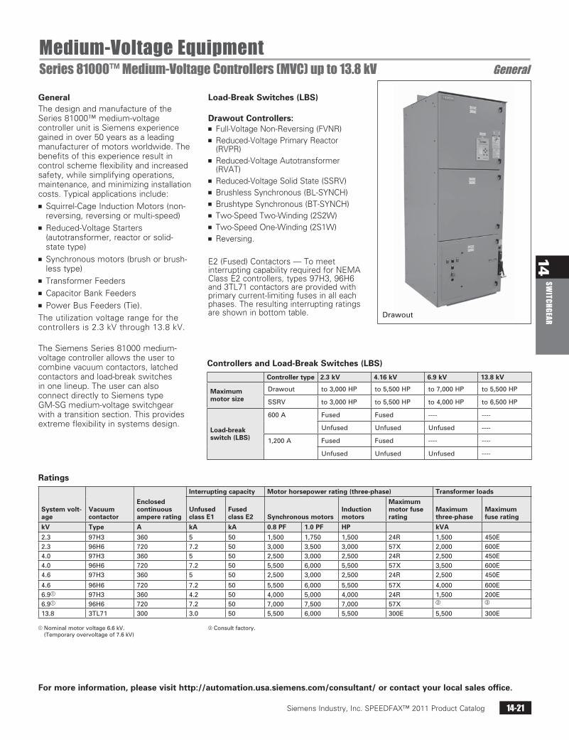
Medium-Voltage EquipmentSeries 81000™ Medium-Voltage Controllers (MVC) up to 13.8 kV General
Drawout
GeneralThe design and manufacture of the Series 81000™ medium-voltage controller unit is Siemens experience gained in over 50 years as a leading manufacturer of motors worldwide. The benefits of this experience result in control scheme flexibility and increased safety, while simplifying operations, maintenance, and minimizing installation costs. Typical applications include:n Squirrel-Cage Induction Motors (non-
reversing, reversing or multi-speed)n Reduced-Voltage Starters
(autotransformer, reactor or solid-state type)
n Synchronous motors (brush or brush-less type)
n Transformer Feedersn Capacitor Bank Feedersn Power Bus Feeders (Tie).
The utilization voltage range for the controllers is 2.3 kV through 13.8 kV.
The Siemens Series 81000 medium-voltage controller allows the user to combine vacuum contactors, latched contactors and load-break switches in one lineup. The user can also connect directly to Siemens type GM-SG medium-voltage switchgear with a transition section. This provides extreme flexibility in systems design.
Load-Break Switches (LBS) Drawout Controllers:n Full-Voltage Non-Reversing (FVNR)n Reduced-Voltage Primary Reactor
(RVPR)n Reduced-Voltage Autotransformer
(RVAT)n Reduced-Voltage Solid State (SSRV)n Brushless Synchronous (BL-SYNCH)n Brushtype Synchronous (BT-SYNCH)n Two-Speed Two-Winding (2S2W)n Two-Speed One-Winding (2S1W)n Reversing.
E2 (Fused) Contactors — To meet interrupting capability required for NEMA Class E2 controllers, types 97H3, 96H6 and 3TL71 contactors are provided with primary current-limiting fuses in all each phases. The resulting interrupting ratings are shown in bottom table.
Controllers and Load-Break Switches (LBS)
Controller type 2.3 kV 4.16 kV 6.9 kV 13.8 kV
Maximum motor size
Drawout to3,000HP to5,500HP to7,000HP to5,500HP
SSRV to3,000HP to5,500HP to4,000HP to6,500HP
Load-break switch (LBS)
600A Fused Fused ---- ----
Unfused Unfused Unfused ----
1,200A Fused Fused ---- ----
Unfused Unfused Unfused ----
Ratings
System volt-age
Vacuum contactor
Enclosed continuous ampere rating
Interrupting capacity Motor horsepower rating (three-phase) Transformer loads
Unfused class E1
Fused class E2 Synchronous motors
Induction motors
Maximum motor fuse rating
Maximum three-phase
Maximum fuse rating
kV Type A kA kA 0.8 PF 1.0 PF HP kVA
2.3 97H3 360 5 50 1,500 1,750 1,500 24R 1,500 450E2.3 96H6 720 7.2 50 3,000 3,500 3,000 57X 2,000 600E4.0 97H3 360 5 50 2,500 3,000 2,500 24R 2,500 450E4.0 96H6 720 7.2 50 5,500 6,000 5,500 57X 3,500 600E4.6 97H3 360 5 50 2,500 3,000 2,500 24R 2,500 450E
4.6 96H6 720 7.2 50 5,500 6,000 5,500 57X 4,000 600E6.9 97H3 360 4.2 50 4,000 5,000 4,000 24R 1,500 200E6.9 96H6 720 7.2 50 7,000 7,500 7,000 57X
13.8 3TL71 300 3.0 50 5,500 6,000 5,500 300E 5,500 300E
Nominalmotorvoltage6.6kV.(Temporaryovervoltageof7.6kV)
Consultfactory.
Siemens Industry, Inc. SPEEDFAX™ 2011 Product Catalog14-22
14SW
ITCH
GEAR
Siemens / Speedfax Previous folio: 13-19 SS 02/08/11
Medium Voltage EquipmentSeries 81000™ Medium-Voltage Controllers (MVC) up to 13.8 kV General
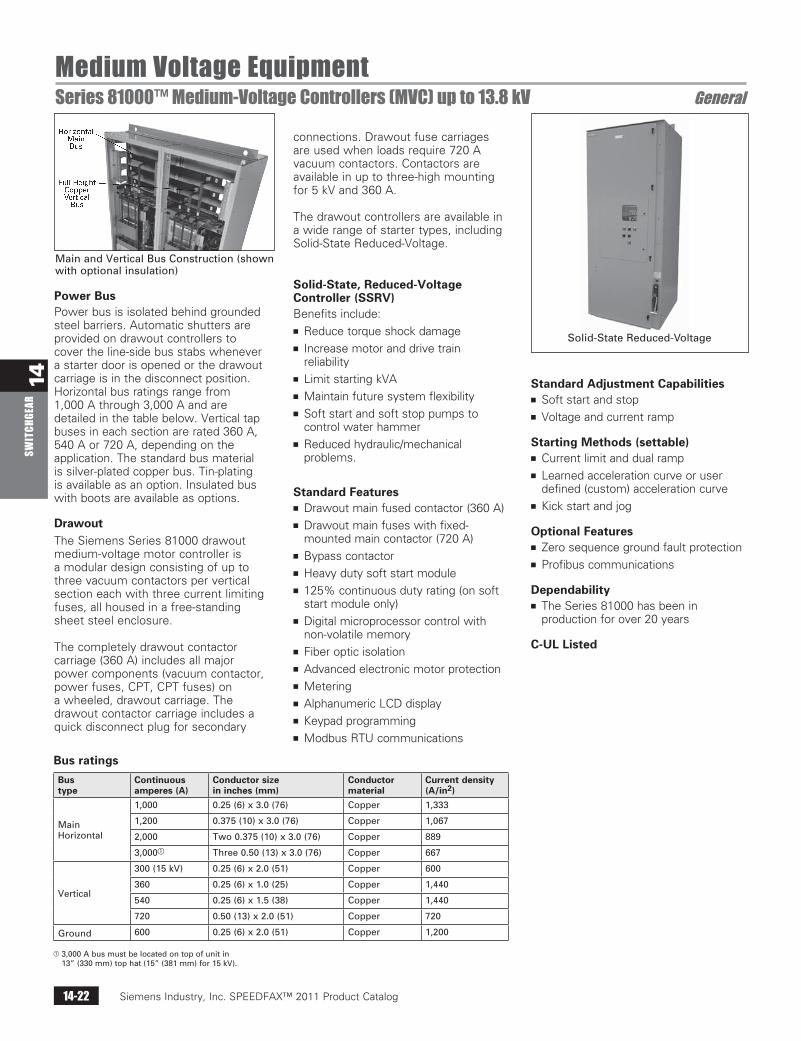
Solid-StateReduced-Voltage
MainandVerticalBusConstruction(shownwithoptionalinsulation)
Power BusPower bus is isolated behind grounded steel barriers. Automatic shutters are provided on drawout controllers to cover the line-side bus stabs whenever a starter door is opened or the drawout carriage is in the disconnect position. Horizontal bus ratings range from 1,000 A through 3,000 A and are detailed in the table below. Vertical tap buses in each section are rated 360 A, 540 A or 720 A, depending on the application. The standard bus material is silver-plated copper bus. Tin-plating is available as an option. Insulated bus with boots are available as options.
DrawoutThe Siemens Series 81000 drawout medium-voltage motor controller is a modular design consisting of up to three vacuum contactors per vertical section each with three current limiting fuses, all housed in a free-standing sheet steel enclosure.
The completely drawout contactor carriage (360 A) includes all major power components (vacuum contactor, power fuses, CPT, CPT fuses) on a wheeled, drawout carriage. The drawout contactor carriage includes a quick disconnect plug for secondary
connections. Drawout fuse carriages are used when loads require 720 A vacuum contactors. Contactors are available in up to three-high mounting for 5 kV and 360 A.
The drawout controllers are available in a wide range of starter types, including Solid-State Reduced-Voltage.
Solid-State, Reduced-Voltage Controller (SSRV)Benefits include:n Reduce torque shock damagen Increase motor and drive train
reliabilityn Limit starting kVAn Maintain future system flexibilityn Soft start and soft stop pumps to
control water hammern Reduced hydraulic/mechanical
problems.
Standard Featuresn Drawout main fused contactor (360 A)n Drawout main fuses with fixed-
mounted main contactor (720 A)n Bypass contactorn Heavy duty soft start modulen 125% continuous duty rating (on soft
start module only)n Digital microprocessor control with
non-volatile memoryn Fiber optic isolationn Advanced electronic motor protectionn Meteringn Alphanumeric LCD displayn Keypad programmingn Modbus RTU communications
Standard Adjustment Capabilitiesn Soft start and stopn Voltage and current ramp
Starting Methods (settable)n Current limit and dual rampn Learned acceleration curve or user
defined (custom) acceleration curven Kick start and jog
Optional Featuresn Zero sequence ground fault protectionn Profibus communications
Dependabilityn The Series 81000 has been in
production for over 20 years
C-UL Listed
Bus ratings
Bus type
Continuous amperes (A)
Conductor size in inches (mm)
Conductor material
Current density (A/in2)
MainHorizontal
1,000 0.25(6)x3.0(76) Copper 1,333
1,200 0.375(10)x3.0(76) Copper 1,067
2,000 Two0.375(10)x3.0(76) Copper 889
3,000 Three0.50(13)x3.0(76) Copper 667
Vertical
300(15kV) 0.25(6)x2.0(51) Copper 600
360 0.25(6)x1.0(25) Copper 1,440
540 0.25(6)x1.5(38) Copper 1,440
720 0.50(13)x2.0(51) Copper 720
Ground 600 0.25(6)x2.0(51) Copper 1,200
3,000Abusmustbelocatedontopofunitin13”(330mm)tophat(15”(381mm)for15kV).
Siemens Industry, Inc. SPEEDFAX™ 2011 Product Catalog 14-23
14SW
ITCHGEAR
Siemens / Speedfax Previous folio: 13-21 SS 02/09/11
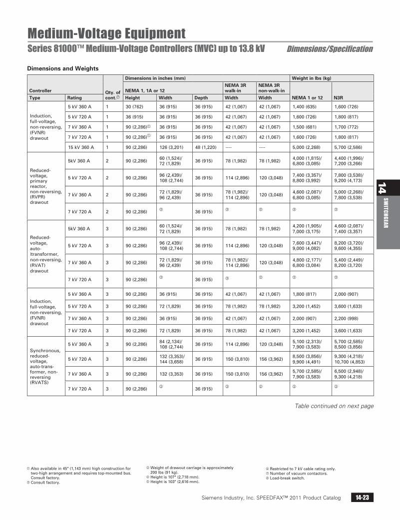
Medium-Voltage EquipmentSeries 81000™ Medium-Voltage Controllers (MVC) up to 13.8 kV Dimensions/Specification
Table continued on next page
Dimensions and Weights
Controller Qty. of cont.g
Dimensions in inches (mm) Weight in lbs (kg)
NEMA 1, 1A or 12NEMA 3R walk-in
NEMA 3R non-walk-in
NEMA 1 or 12 N3RType Rating Height Width Depth Width Width
Induction,full-voltage,non-reversing,(FVNR)drawout
5kV360A 1 30(762) 36(915) 36(915) 42(1,067) 42(1,067) 1,400(635) 1,600(726)
5kV720A 1 36(915) 36(915) 36(915) 42(1,067) 42(1,067) 1,600(726) 1,800(817)
7kV360A 1 90(2,286) 36(915) 36(915) 42(1,067) 42(1,067) 1,500(681) 1,700(772)
7kV720A 1 90(2,286) 36(915) 36(915) 42(1,067) 42(1,067) 1,600(726) 1,800(817)
15kV360A 1 90(2,286) 126(3,201) 48(1,220) ---- ---- 5,000(2,268) 5,700(2,586)
Reduced-voltage,primaryreactor,non-reversing,(RVPR)drawout
5kV360A 2 90(2,286) 60(1,524)/72(1,829) 36(915) 78(1,982) 78(1,982) 4,000(1,815)/
6,800(3,085)4,400(1,996)/7,200(3,266)
5kV720A 2 90(2,286) 96(2,439)/108(2,744) 36(915) 114(2,896) 120(3,048) 7,400(3,357)/
8,800(3,992)7,800(3,538)/9,200(4,173)
7kV360A 2 90(2,286) 72(1,829)/96(2,439) 36(915) 78(1,982)/
114(2,896) 120(3,048) 4,600(2,087)/6,800(3,085)
5,000(2,268)/7,800(3,538)
7kV720A 2 90(2,286)
36(915)
Reduced-voltage,auto-|transformer,non-reversing,(RVAT)drawout
5kV360A 3 90(2,286) 60(1,524)/72(1,829) 36(915) 78(1,982) 78(1,982) 4,200(1,905)/
7,000(3,175)4,600(2,087)/7,400(3,357)
5kV720A 3 90(2,286) 96(2,439)/108(2,744) 36(915) 114(2,896) 120(3,048) 7,600(3,447)/
9,000(4,082)8,200(3,720)/9,600(4,355)
7kV360A 3 90(2,286) 72(1,829)/96(2,439) 36(915) 78(1,982)/
114(2,896) 120(3,048) 4,800(2,177)/6,800(3,084)
5,400(2,449)/8,200(3,720)
7kV720A 3 90(2,286)
36(915)
Induction,full-voltage,non-reversing,(FVNR)drawout
5kV360A 3 90(2,286) 36(915) 36(915) 42(1,067) 42(1,067) 1,800(817) 2,000(907)
5kV720A 3 90(2,286) 72(1,829) 36(915) 78(1,982) 78(1,982) 3,200(1,452) 3,600(1,633)
7kV360A 3 90(2,286) 36(915) 36(915) 42(1,067) 42(1,067) 2,000(907) 2,200(998)
7kV720A 3 90(2,286) 72(1,829) 36(915) 78(1,982) 42(1,067) 3,200(1,452) 3,600(1,633)
Synchronous,reduced-voltage,auto-trans-former,non-reversing(RVATS)
5kV360A 3 90(2,286) 84(2,134)/108(2,744) 36(915) 114(2,896) 120(3,048) 5,100(2,313)/
7,900(3,583)5,700(2,585)/8,500(3,856)
5kV720A 3 90(2,286) 132(3,353)/144(3,658) 36(915) 150(3,810) 156(3,962) 8,500(3,856)/
9,900(4,491)9,300(4,218)/10,700(4,853)
7kV360A 3 90(2,286) 132(3,353) 36(915) 150(3,810) 156(3,962) 5,700(2,585)/7,900(3,583)
6,500(2,948)/9,300(4,218)
7kV720A 3 90(2,286)
36(915)
Alsoavailablein45"(1,143mm)highconstructionfortwo-higharrangementandrequirestop-mountedbus.Consultfactory.
Consultfactory.
Weightofdrawoutcarriageisapproximately200lbs(91kg).
Heightis107"(2,718mm).Heightis103"(2,616mm).
Restrictedto7kVcableratingonly.gNumberofvacuumcontactors.h Load-breakswitch.
Siemens Industry, Inc. SPEEDFAX™ 2011 Product Catalog14-24
14SW
ITCH
GEAR
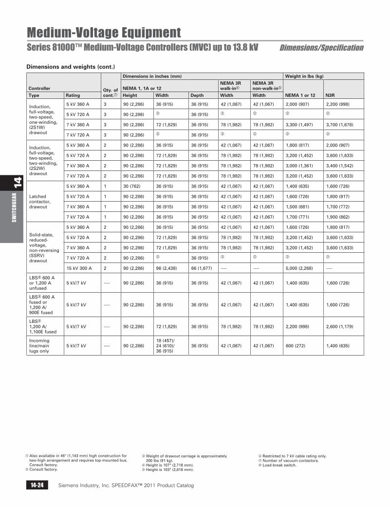
Medium-Voltage EquipmentSeries 81000™ Medium-Voltage Controllers (MVC) up to 13.8 kV Dimensions/Specification
Dimensions and weights (cont.)
Controller Qty. of cont.g
Dimensions in inches (mm) Weight in lbs (kg)
NEMA 1, 1A or 12NEMA 3R walk-in
NEMA 3R non-walk-in
NEMA 1 or 12 N3RType Rating Height Width Depth Width Width
Induction,full-voltage,two-speed,one-winding,(2S1W)drawout
5kV360A 3 90(2,286) 36(915) 36(915) 42(1,067) 42(1,067) 2,000(907) 2,200(998)
5kV720A 3 90(2,286) 36(915)
7kV360A 3 90(2,286) 72(1,829) 36(915) 78(1,982) 78(1,982) 3,300(1,497) 3,700(1,678)
7kV720A 3 90(2,286) 36(915)
Induction,full-voltage,two-speed,two-winding,(2S2W)drawout
5kV360A 2 90(2,286) 36(915) 36(915) 42(1,067) 42(1,067) 1,800(817) 2,000(907)
5kV720A 2 90(2,286) 72(1,829) 36(915) 78(1,982) 78(1,982) 3,200(1,452) 3,600(1,633)
7kV360A 2 90(2,286) 72(1,829) 36(915) 78(1,982) 78(1,982) 3,000(1,361) 3,400(1,542)
7kV720A 2 90(2,286) 72(1,829) 36(915) 78(1,982) 78(1,982) 3,200(1,452) 3,600(1,633)
Latchedcontactor,drawout
5kV360A 1 30(762) 36(915) 36(915) 42(1,067) 42(1,067) 1,400(635) 1,600(726)
5kV720A 1 90(2,286) 36(915) 36(915) 42(1,067) 42(1,067) 1,600(726) 1,800(817)
7kV360A 1 90(2,286) 36(915) 36(915) 42(1,067) 42(1,067) 1,500(681) 1,700(772)
7kV720A 1 90(2,286) 36(915) 36(915) 42(1,067) 42(1,067) 1,700(771) 1,900(862)
Solid-state,reduced-voltage,non-reversing(SSRV)drawout
5kV360A 2 90(2,286) 36(915) 36(915) 42(1,067) 42(1,067) 1,600(726) 1,800(817)
5kV720A 2 90(2,286) 72(1,829) 36(915) 78(1,982) 78(1,982) 3,200(1,452) 3,600(1,633)
7kV360A 2 90(2,286) 72(1,829) 36(915) 78(1,982) 78(1,982) 3,200(1,452) 3,600(1,633)
7kV720A 2 90(2,286) 36(915)
15kV300A 2 90(2,286) 96(2,438) 66(1,677) ---- ---- 5,000(2,268) ----
LBSh600Aor1,200Aunfused
5kV/7kV ---- 90(2,286) 36(915) 36(915) 42(1,067) 42(1,067) 1,400(635) 1,600(726)
LBSh600Afusedor1,200A/900Efused
5kV/7kV ---- 90(2,286) 36(915) 36(915) 42(1,067) 42(1,067) 1,400(635) 1,600(726)
LBSh1,200A/1,100Efused
5kV/7kV ---- 90(2,286) 72(1,829) 36(915) 78(1,982) 78(1,982) 2,200(998) 2,600(1,179)
Incomingline/mainlugsonly
5kV/7kV ---- 90(2,286)18(457)/24(610)/36(915)
36(915) 42(1,067) 42(1,067) 600(272) 1,400(635)
Alsoavailablein45"(1,143mm)highconstructionfortwo-higharrangementandrequirestop-mountedbus.Consultfactory.
Consultfactory.
Weightofdrawoutcarriageisapproximately200lbs(91kg).
Heightis107"(2,718mm).Heightis103"(2,616mm).
Restrictedto7kVcableratingonly.gNumberofvacuumcontactors.h Load-breakswitch.
Siemens Industry, Inc. SPEEDFAX™ 2011 Product Catalog 14-25
14SW
ITCHGEAR
For more information, please visit http://automation.usa.siemens.com/consultant/ or contact your local sales office.
Siemens / Speedfax Previous folio: 13-18
Medium Voltage EquipmentSeries 81000™ Medium-Voltage Controllers (MVC) up to 7.2 kV Protective Relaying
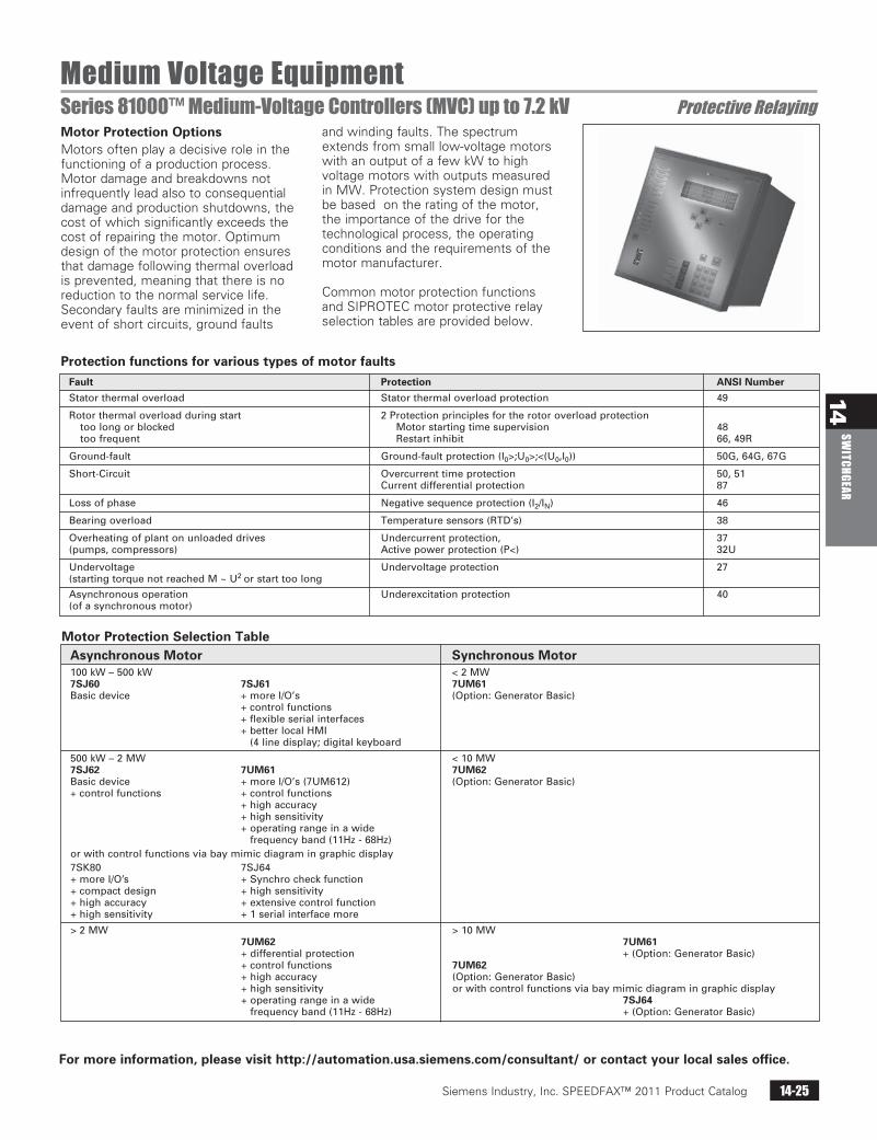
Motor Protection Selection Table Asynchronous Motor Synchronous Motor 100kW–500kW <2MW 7SJ60 7SJ61 7UM61 Basicdevice +moreI/O’s (Option:GeneratorBasic) +controlfunctions +flexibleserialinterfaces +betterlocalHMI
(4linedisplay;digitalkeyboard
500kW–2MW <10MW 7SJ62 7UM61 7UM62 Basicdevice +moreI/O’s(7UM612) (Option:GeneratorBasic) +controlfunctions +controlfunctions +highaccuracy +highsensitivity +operatingrangeinawide
frequencyband(11Hz-68Hz) orwithcontrolfunctionsviabaymimicdiagramingraphicdisplay 7SK80 7SJ64 +moreI/O’s +Synchrocheckfunction +compactdesign +highsensitivity +highaccuracy +extensivecontrolfunction +highsensitivity +1serialinterfacemore
>2MW >10MW 7UM62 7UM61 +differentialprotection +(Option:GeneratorBasic) +controlfunctions 7UM62 +highaccuracy (Option:GeneratorBasic) +highsensitivity orwithcontrolfunctionsviabaymimicdiagramingraphicdisplay +operatingrangeinawide 7SJ64
frequencyband(11Hz-68Hz) +(Option:GeneratorBasic)
Motor Protection OptionsMotors often play a decisive role in the functioning of a production process. Motor damage and breakdowns not infrequently lead also to consequential damage and production shutdowns, the cost of which significantly exceeds the cost of repairing the motor. Optimum design of the motor protection ensures that damage following thermal overload is prevented, meaning that there is no reduction to the normal service life. Secondary faults are minimized in the event of short circuits, ground faults
and winding faults. The spectrum extends from small low-voltage motors with an output of a few kW to high voltage motors with outputs measured in MW. Protection system design must be based on the rating of the motor, the importance of the drive for the technological process, the operating conditions and the requirements of the motor manufacturer.
Common motor protection functions and SIPROTEC motor protective relay selection tables are provided below.
Protection functions for various types of motor faults Fault Protection ANSI Number
Statorthermaloverload Statorthermaloverloadprotection 49
Rotorthermaloverloadduringstart 2Protectionprinciplesfortherotoroverloadprotection toolongorblocked Motorstartingtimesupervision 48 toofrequent Restartinhibit 66,49R
Ground-fault Ground-faultprotection(I0>;U0>;<(U0,I0)) 50G,64G,67G
Short-Circuit Overcurrenttimeprotection 50,51 Currentdifferentialprotection 87
Lossofphase Negativesequenceprotection(I2/IN) 46
Bearingoverload Temperaturesensors(RTD’s) 38
Overheatingofplantonunloadeddrives Undercurrentprotection, 37 (pumps,compressors) Activepowerprotection(P<) 32U
Undervoltage Undervoltageprotection 27 (startingtorquenotreachedM~U2orstarttoolong
Asynchronousoperation Underexcitationprotection 40 (ofasynchronousmotor)
Siemens Industry, Inc. SPEEDFAX™ 2011 Product Catalog14-26
14SW
ITCH
GEAR
Siemens / Speedfax Previous folio: 13-27
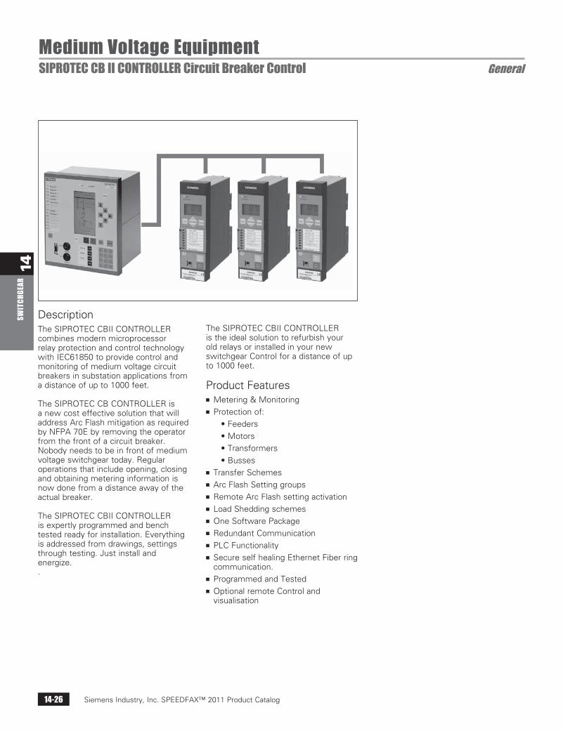
Medium Voltage EquipmentSIPROTEC CB II CONTROLLER Circuit Breaker Control General
DescriptionThe SIPROTEC CBII CONTROLLER combines modern microprocessor relay protection and control technology with IEC61850 to provide control and monitoring of medium voltage circuit breakers in substation applications from a distance of up to 1000 feet.
The SIPROTEC CB CONTROLLER is a new cost effective solution that will address Arc Flash mitigation as required by NFPA 70E by removing the operator from the front of a circuit breaker. Nobody needs to be in front of medium voltage switchgear today. Regular operations that include opening, closing and obtaining metering information is now done from a distance away of the actual breaker.
The SIPROTEC CBII CONTROLLER is expertly programmed and bench tested ready for installation. Everything is addressed from drawings, settings through testing. Just install and energize. .
The SIPROTEC CBII CONTROLLER is the ideal solution to refurbish your old relays or installed in your new switchgear Control for a distance of up to 1000 feet.
Product Featuresn Metering & Monitoringn Protection of:
• Feeders
• Motors
• Transformers
• Bussesn Transfer Schemesn Arc Flash Setting groupsn Remote Arc Flash setting activationn Load Shedding schemesn One Software Packagen Redundant Communicationn PLC Functionalityn Secure self healing Ethernet Fiber ring
communication.n Programmed and Testedn Optional remote Control and
visualisation
Siemens Industry, Inc. SPEEDFAX™ 2011 Product Catalog 14-27
14SW
ITCHGEAR
Siemens / Speedfax Previous folio: 13-36
Packaged Power Solutions (PPS)Power Equipment Centers General
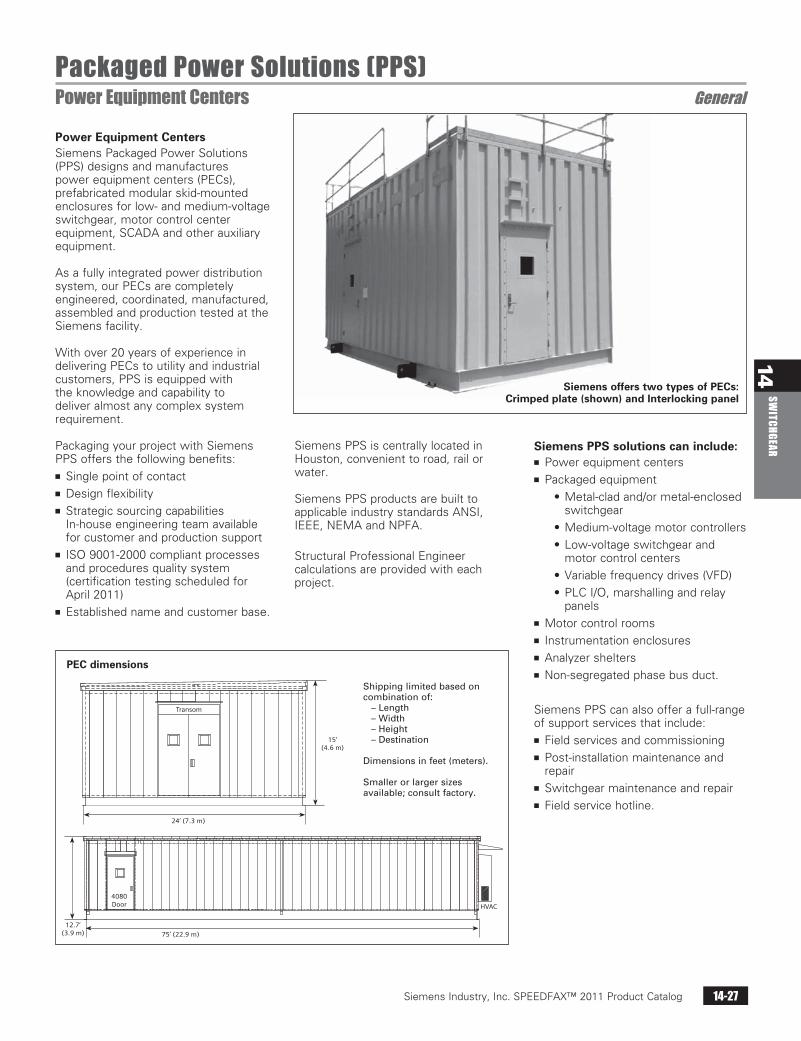
Power Equipment CentersSiemens Packaged Power Solutions (PPS) designs and manufactures power equipment centers (PECs), prefabricated modular skid-mounted enclosures for low- and medium-voltage switchgear, motor control center equipment, SCADA and other auxiliary equipment.
As a fully integrated power distribution system, our PECs are completely engineered, coordinated, manufactured, assembled and production tested at the Siemens facility.
With over 20 years of experience in delivering PECs to utility and industrial customers, PPS is equipped with the knowledge and capability to deliver almost any complex system requirement.
Packaging your project with Siemens PPS offers the following benefits:n Single point of contactn Design flexibilityn Strategic sourcing capabilities
In-house engineering team available for customer and production support
n ISO 9001-2000 compliant processes and procedures quality system (certification testing scheduled for April 2011)
n Established name and customer base.
Transom
24’ (7.3 m)
15’ (4.6 m)
75’ (22.9 m)12.7’
(3.9 m)
4080 Door HVAC
Siemens PPS is centrally located in Houston, convenient to road, rail or water.
Siemens PPS products are built toapplicable industry standards ANSI, IEEE, NEMA and NPFA.
Structural Professional Engineercalculations are provided with eachproject.
Siemens PPS solutions can include:n Power equipment centersn Packaged equipment
• Metal-clad and/or metal-enclosed switchgear
• Medium-voltage motor controllers
• Low-voltage switchgear and motor control centers
• Variable frequency drives (VFD)
• PLC I/O, marshalling and relay panels
n Motor control roomsn Instrumentation enclosuresn Analyzer sheltersn Non-segregated phase bus duct.
Siemens PPS can also offer a full-range of support services that include:n Field services and commissioningn Post-installation maintenance and
repairn Switchgear maintenance and repairn Field service hotline.
Shippinglimitedbasedoncombinationof: –Length –Width –Height –Destination
Dimensionsinfeet(meters).
Smallerorlargersizesavailable;consultfactory.
Siemens offers two types of PECs:Crimped plate (shown) and Interlocking panel
PEC dimensions