speleonics 27 - caves.orgcaves.org/section/commelect/splncs/splncs27.pdf · speleonics 27 - june...
TRANSCRIPT

SPELEONICS 27 - June 2011 - Page 1 of 34
SPELEONICS 27 COMMUNICATIONS AND ELECTRONICS SECTION
OF THE NATIONAL SPELEOLOGICAL SOCIETY
Volume VII #3 Editor: Paul R. Jorgenson KE7HR
June 2011 NSS 39382 RLFE [email protected]
SPELEONICS is published irregularly by the Communications and Electronics
Section (CES) of the National Speleological Society (NSS). Primary interests include
cave radio, underground communication, cave lighting, and cave related applications
of amateur radio. NSS membership is not required.
Contributions of articles for publication is highly encouraged.
All issues of SPELEONICS are available online for FREE: http://www.caves.org/section/commelect/spelonic.html
Contents of SPELEONICS 26 - Volume VII #3
1 Title, Table of Contents
2—4 Frank Reid Remembered
5 Radio Slave for Flash by Alan Beswick
6 – 7 185 KHz Ferrite Core Antenna by Paul R. Jorgenson KE7HR
8—9 Radio Propagation Testing in Lava Tubes by Jansen Cardy
10—14 Carlsbad Caverns Radio Caving by Paul R. Jorgenson KE7HR
15—23 Very High Power Radiobeacon by Brian Pease W1IR
24—25 The TP-6N Field Telephone by Jansen Cardy
26 Simple Phone Line Amplifier by Jansen Cardy
27 Modifying the Classic Phone Patch by Jansen Cardy
28—29 C&E Minutes 2007 and Langdon’s Cave Field Day Photos
30 C&E Minutes 2008
31 C&E Minutes 2009
32 C&E Minutes 2010
33 C&E Session 2010
34-35 Fun Graphics and Editor Notes

SPELEONICS 27 - June 2011 - Page 2 of 34
Frank Reid Remembered Compiled by Paul R. Jorgenson KE7HR
I first heard of Frank Reid, W9MKV, in February of 1984 when an article with the title “Caveman Radio” was published in 73 Magazine, a ham radio publication. Even though I was not involved in organized caving at the time I thought it was a novel concept. Frank Reid was one of the founding members of the Communica-tions and Electronics Section in 1985, along with Joe Giddens and Ian Drummond. “Better Caving Through Electrical Stuff” was the motto published in the first issue of SPELEONICS. Frank had a hand in shaping the Section and keeping it going from SPELEONICS 1 to SPELEONICS 21 spanning 1985 to 1997. I met Frank at the Salida Colorado Convention in 1996. We played with lasers and bat detectors in the night at
the campground. He had a great style and I was glad to have had the personal acquaintance as well as hav-ing read numerous articles written by him. Frank suffered a heart attack in Saltpeter Cave and subsequently died on January 24, 1998. SPELEONICS took a hiatus until 2001. As many did over the years, I learned a lot from Frank through his writings. Writers know little of the minds that they touch with their articles, but the effect can be great. Following are excerpts from online sources and emails relating to Frank Reid and his contributions to caving and electronics. They are in no particular order, but Frank might have liked it that way… Excerpt from Joe Giddens email, January 2008 FRANK REID was much more than a caver. He wrote some interesting material in the process of learning to use a word process-ing program - and back in 1983 - these were not user friendly. One was a spoof of "Soldier of Fortune" (a mercenary oriented arms rag) called "Caver of Fortune". We sold a few at Cave meets. The "TRICKS, DIRTY" booklet series also started in 1983 and never seem to die as folks kept sending him more material. The series went on for "AWFUL, NASTY, HORRID, ROTTEN, EVIL, WICKED, and finally EVIL" and so on until 1995. I was aggravating him to publish "TRICKS, HUMEROUS". In the later years of his life, he enjoyed the humor of performing as a cave balladeer. Frank had his own humor, look at some of the car-toons in SPELEONICS. I had called Frank in 1983 or early 1984 to get him to chair a new radio oriented section. That did not click at first as we were both adamant about NOT being the chair. I did not think the section would work without him, nor was I going to start it without him. We did agree to start the section that exists today and started a search for a third person that would agree to be the chair. Frank had a phobia about "speleopoliticians". To digress for a bit, Frank was the quintessential electronics experimenter. The frat rats (his words) at the university in Bloomington were partial to sporty BMWs at the time while Frank drove a diesel VW Rabbit. The BMW drivers were generally impatient - and diesel Rabbits were slow accelerators - and they would cut him off coming onto a freeway and pass him. When this happened, he would pick up his antique "STAR TREK" plastic toy phaser pistol and "fire phasers"! The pistol contained a battery, wave guide and a GUNN diode with the same frequency as police radar. He would be rewarded with red brake lights and would then pass the BMW. For the other radar frequencies, a cigar box with a larger Gunn diode and wave guide joined the phaser pistol in the car. Frank came to Texas when I lived there and used a LORAN system (pre GPS days) in his car. He was disappointed when it was a
(Continued on page 3)

SPELEONICS 27 - June 2011 - Page 3 of 34
bit off when he arrived as it had been on track until he turned south of Fort Worth. He was mollified to find out from another (pilot) visitor there that the third leg of the LORAN in the area was inaccurate and due for repair. LORAN was a consideration for accurate cave location and I had an inoperable (and uneconomic repair as it turned out) LORAN unit at the time. The discussion of this unit and LORAN in general was a part of a continuing search to adapt electronics and particularly AVIONICS for cav-ing. The newsletter was also a current topic of discussion and SPELEONICS came from those rolling conversations. RADIO UNDERGROUND was considered briefly and we did not want to call it AVIONICS UNDERGROUND! That had a logical conclusion. Along that time, Frank found news of some Canadians, Julian Coward and Ian Drummond, that had developed an underground radio for the Canadian Health folks to enable communications with survivors in a mine incident. Ian Drummond became our chair. We had already written a constitution and section application paperwork. Ian added additional charter members and the item was bundled to the NSS. When the Section Application was reviewed, a director went on a tirade about "these frivolous sec-tions with few members". Evelyn Bradshaw, Internal Organizations chair at the time, let him wind down and then asked if 100+ members would be OK. Jay Jorden KA5YVC of Dallas drew the first cover, Diana George N9DEJ of Kentucky published it and SPELEONICS #1 was out in 1985. Frank had a great time as the main editor while we had contributed material. His ability get think out-of-the-box was EXTREMELY WAY-out-of-the-box and even the most serious subject was game for some REID humor. He and that great mind is sorely missed. IN AFTERMATH: Frank was disappointed in the mid 1990s in the amount of publication material sent. Folks wanted a more regular publication, but we had vowed not to publish junk or issues without good material. When the idea of an online forum or newsletter came out, it looked like a good direction to revive contribution to the subject and the section. Newsletters were increasingly going electronic and paperless. We hoped the section would benefit. In hindsight, it was the thing to do in my opinion, but there were some nervo-ous phone calls at the time. Now there are few printed newsletters. Newsletters are the glue that hold a diverse and widespread group of folks together. Communications is the key indeed. The Section was always intended - at least by the founders - to be free and open as possible. Our dues barely covered postage at the time. Membership was not only NSS as we had many electronics experimenters initially. Such folk contribute to the end result whether they have ever been in a cave and are a needed part of a technical group. SPELEONICS today seems more of a forum and articles and designs are published elsewhere with subscription required. This causes a reduced audience and less participation of experimenters due to costs. Early items of interest included microgravity and/or micro magnetic surveys, ground penetrating radar in addition to "cave radio". Some of this is still untouched, but some has been used in DMZ tunnel searches in Korea and should be - maybe is - in El Paso and San Diego. These are still good areas for "earthy electronics". W9MKV Frank, You might have never learned my name but I learned yours. You might not have known that I had learned from you but I did. From cave rescue to ham radio to just being a good person, I will be remembering what you did for me. Thank you and God speed, 73 KB9LTH Chris
My husband knew Frank for many years via the NSS, and my brother (WB0MHU) via the Dayton Hamvention. I first met him at the sing-along at the 1993 Indiana NSS Convention, and was impressed with the wide range of a person who seemed equally at home with a beer in one hand and a guitar in another, or promoting some great scheme involv-ing field telephones or artificial entrance enlargement (Better Caving through Chemistry). But the best story which most typifies his many-faceted character and which involved us is:
The Great Soldering Iron Caper At the 1995 National Cave Management Symposium (NCMS) Spring Mill State Park, Mitchell, Indiana
As many who read this know, the NCMS is a gathering of cave owners, cave managers, cavers and other interested people who come to learn new techniques for managing caves. These techniques are exchanged both formally in twenty minute presentations and demonstrations, and informally. On Friday October 27, Frank came down to give a presentation on Cave Radio as a Management Tool, which was to be followed by Jeff Moll of Lincoln National Forest
(Continued from page 2)
(Continued on page 4)

SPELEONICS 27 - June 2011 - Page 4 of 34
(New Mexico) on Use of a Laser System to Survey Caves.
Jeff's presentation was to include a demonstration of a $12,000 survey laser--an electronic gizmo which takes read-ings suitable for conversion into CAD data, thereby computerizing the map making process. After Moll and Ransom Turner unpacked their delicate electronic equipment, they discovered that one of the connecting cables was broken, after having been slammed in a door, rendering the unit inoperable.
Eugene Vale had hauled our computer to the meeting, and he ran into the duo in the hall having trouble. He volun-teered to see if any of our computer cables could be used as a patch to enable them to make their presentation. No go. I came up to our room for something, and found Eugene had stepped out, strange men in my room, cables and gear spread everywhere, and these people wishing for a soldering iron. "Gee, who here would be most likely to have a soldering iron?" Only one name came up. Frank Reid.
So I went in search of Frank.
As it turned out, Frank had just recently arrived, and was talking to people in the dining room. "Hi, Frank," I said, blurt-ing into some conversation. "I've been sent to look for you. There's some people upstairs wondering if you had a sol-dering iron." He looked a bit quizzical. "I know I have some solder. Let me go look in the car."
I gave him the room number, and went back upstairs. Frank arrived with a roll of solder. "I didn't bring my iron," he said, "but I have a butane torch, and a coat hanger." He cut off a length of metal coat hanger, and heated it with the torch. "This should work, you know," he said. I just looked on in disbelief, as he attempted to melt the solder with the heated coat hanger, in an attempt to fix the broken cable. Despite the application of solder, the unit refused to work. In the meantime, Moll decided to forego the demonstration, and stick with his slideshow, so Frank left, as he had his own presentation to prepare for.
That is the image of Frank Reid which will forever stick in our minds: hunched over a hotel table, a blowtorch in one hand, a hot coat hanger in the other, trying to fix a piece of electronic equipment which cost more than my truck.
We're very lucky to have known him.
73s, Frank, until we too hit that final code key in the sky.
Jo Schaper and Eugene Vale
NSS 27624L & 19197FL
(Continued from page 3)

SPELEONICS 27 - June 2011 - Page 5 of 34
Radio Slave for Flash Alan Beswick
A very simple remote trigger for open flash photography. Many remote triggers exist for remotely triggering flashlights for cave photography. Most of these have some circuitry to trigger the remote flash from the flash from a camera, but is this really necessary??? Perhaps it just complicates things. Back in my youth, as a member of the University of Queensland Speleological Society when Queensland's caves had neither been flooded nor mined, photography was done using open flash techniques, wandering around in total darkness, pressing the open flash button on the flashlights and leaving ghostly figures in the photos. Nowadays, many hardware manufacturers do 99.9% of the hard work for us (you) by making wireless door chimes (eg http://arlec.com.au/pdfs/ doorchimes_security.pdf) , with a radio transmitter in the press button component and a receiver in the bell.
One additional component is needed, a readily available 4n25 optocoupler (http://www.jaycar.com.au/products_uploaded/ZD1928.pdf), plus a bit of wire. The 4n25 is a 6 pin integrated circuit, and I'm not even going to give a circuit diagram. Pin 1 will have a dimple adjacent to it so it can't be confused with pin 4 if the chip is the wrong way around. Remove the two wires from the loudspeaker and solder these onto pins 1 & 2. If you are like me, you'll get then around the wrong way but no harm will be done. Pins 4 and 5 go to the flash gun, using a PC flash sync cable (search eBay for these). A dab of Super Glue to hold the 4N25 onto the case and that's it! Press the door bell and the flash will fire. Again, you might get the cable round the wrong way. There are 4 possible ways to wire up this thing, and only one works. The transmitter/receiver pairs have 16 channels, so you can follow the manufacturers instructions to change channels to avoid firing your friends' flashes. And best of all, they are small enough to fit into a condom for wet caves. Range seems to be about 50m for the cheapest door chime, but there are more powerful models available. Why isn't this useful above ground? Because, if the camera is hooked up to the door pushbutton, the sync speed is 1/8", too slow for daylight use, but fine for pho_trog_raphy. It is currently in pieces as I try to speed it up, so no photo of the finished article. Have fun, Alan Beswick

SPELEONICS 27 - June 2011 - Page 6 of 34
185 KHz Ferrite Core Antenna Paul R. Jorgenson KE7HR
I did some experiments with some small ferrite core antennas for 185 kHz. It was a ¾ inch ferrite rod, 12 inches long (yes, expensive), with full windings along the length and appropriate tuning capacitors. They performed surprisingly well, being able to trans-mit and receive through several hundred feet of rock using a CB to LF transverter. There are commercially available versions of this antenna that have been available for some years now. This inspired me to see what could be done with easily obtained materials. I saw some ferrite rods on eBay and bought them, cheaply. They are 3 ½ inches long and about 3/8 inch in diameter. (The seller had no idea of what ma-terial they were make of or what the permeability was.) I glued three of the rods together side by side in a kind of triangle. Three of those units were stacked end to end inside a piece of ¾ inch PVC pipe to pro-duce a rod that is 10 ½ inches long. The pipe had to be relieved a bit with a round file to accommodate the triangles. The extra space in the pipe was filled with a kitchen and bath adhesive caulk to keep the pieces from moving around if the glue fails or if a shock were to break the rod. End caps were installed on this assembly. The coil winding was done with #22 insulated hook up wire. More inductance than I wanted was found by close winding the coil. By separating the turns by about one wire space, the desired 300 uH value was achieved. Electrical tape was used to keep the wind-ings from moving on the PVC form. The complete wound core was placed inside a 1 ½ inch PVC pipe using a closed cell foam packing mate-rial to keep the core centered in the outer pipe.
One end of the outer pipe was solidly capped and the other has a screw off cap and Teflon tape to keep the threads from sticking. Inside the screw off cap, a barrier strip connects the ends of the coil, the resonating capacitors (about 2000 pF), and the coax to a BNC connector. More packing foam keeps everything stable inside the pipe. The outside of the large pipe was flattened to ac-commodate the nut for the BNC connector.
I chose to use the matching method of a series variable capacitor (a mica compression unit rather than a matching transformer or inductive link of one or more turns over the main coil. I think that this is a more e f f i c i e n t wa y o f transferring the power to
(Continued on page 7)

SPELEONICS 27 - June 2011 - Page 7 of 34
the antenna With the proper equipment is has been easy to adjust to resonance. An analysis with my Mini VNA network analyzer shows that the resonant point is quite sharp and can be moved up and down the band by adjusting the matching variable capacitor. The antenna easily reaches resonance and a match to 50 ohm coax and has acceptable bandwidth for the purpose for which it will be used. The sharp tuning should keep out of band signals and noise to a minimum. This is important at LF where there is lots of noise!
(Continued from page 6)

SPELEONICS 27 - June 2011 - Page 8 of 34
Radio Propagation Testing in Lava Tubes
By Jansen Cardy, ZL1AAB Cave Research Foundation Volunteer, Lava Beds National Monument
On November 27 2005, I conducted a brief radio communication experiment in Valentine Cave at Lava Beds NM, California. Assisting me was CRF volunteer Bill Frantz. The purpose of this experi-ment was to compare the usable range of Very High Frequency (VHF) radios, against the range of some High Frequency (HF) Citizen Band (CB) radios. The VHF radios we used were a pair of Yaesu FT-50 amateur radio handhelds, on a frequency of 147 Megahertz (MHz) using Frequency Modulation (FM) mode. The standard National Park Service VHF radios used at Lava Beds operate around 171 MHz FM, and we expected our radios to perform similarly. During testing, both radios were adjusted between low and high power (0.5 to 3.5 watts). One radio had a quarter-wave whip antenna (about 20 inches long), and the other had a short ‘rubber ducky’ antenna (about 7 inches long – similar to those used on the NPS radios).
The CB radios we used for comparison were a pair of GE 3-5980 walkie-talkies, set to low power (about 1 watt) on a frequency of 27 MHz using Amplitude Modulation (AM) mode. Each radio was connected to a dipole antenna constructed from a pair of 3-foot CB vehicle whips, mounted to the end of a PVC tube in a ‘T’ configuration. It should be noted that although our VHF radios have a built-in signal strength meter, the CB radios do not. Therefore our assessments of the CB signals were made purely ‘by ear’. We began testing with Bill positioned in the entrance room, while I made my way further into the cave. About 400 feet down the passage it became difficult to communicate with the VHF radios, so Bill and I both increased our radios to high power and low-ered the squelch thresholds (which makes the reception more sensitive). By the time I got about 700 feet from the entrance, all effective VHF communication was lost. The CB radios continued to operate flawlessly on low power. After we lost VHF communication, I stopped and established a testing location in the Bubble Distributary section of the cave. I was now about 750 feet (in a straight line) from Bill in the entrance room. The passage at this point was about 7 feet wide by 4 feet high, which I judged to be about the minimum size needed to effectively test the dipole antenna. We began this phase of test-ing with both our antennas horizontally polarized. In this configuration a dipole is bi-directional, and we positioned ours to trans-mit to each other approximately north-south along the trend of the cave passage. While receiving, I found that when the tips of my antenna got within a couple of inches of the rock, or touched it, the signal would be sharply attenuated (causing Bill’s voice to fade out). Because of the low ceiling height, I could not test my dipole in a vertical orientation. Bill tried with his dipole positioned vertically, but it seemed to make no difference to the high signal quality. How-ever, he did comment that my signal sounded slightly weaker when his antenna was on a diagonal slant. We then tested with both antennas back in the horizontal position but now pointed the ‘wrong’ way, transmitting approximately east-west perpendicular to the trend of the cave passage. We experienced a slight loss of signal strength, but we still had good communication. For the next phase of testing, Bill exited the cave and walked along the surface following the direction of the lava tube below. Again, the CB radios continued to operate flawlessly, still on low power. Communication by VHF radio was re-established not long after Bill exited the cave, and became full strength as he got closer to being directly above my position. He then went back into the entrance room, and we tested our CB radios with one dipole element removed (making them simple 3-foot whip anten-nas). The result was a substantial loss in signal strength, but we were still easily able to understand each other. That concluded
(Continued on page 9)
Bill Franz using the radio.

SPELEONICS 27 - June 2011 - Page 9 of 34
our testing. I have been able to draw several broad conclusions from this brief experiment. Firstly, the CB radios had a significantly longer range when transmitting in these particular caves than our VHF radios did. The 27 MHz signal either travels directly through these lava tubes more efficiently, or perhaps it penetrates the relatively shallow overburden and travels longer distances above the surface before being received by the other underground station. Secondly, as expected, using a dipole antenna increased the range when compared with a simple whip antenna. Thirdly, having each dipole antenna polarized differently did not seem to affect the range as much underground as it often can above ground. And finally, allowing any antennas to touch or be too near the rock at-tenuated the signal and greatly reduced reception.
(Continued from page 8)
SPELEONICS 27 - June 2011 - Page 10 of 34
Carlsbad Caverns Radio Caving Paul R. Jorgenson KE7HR
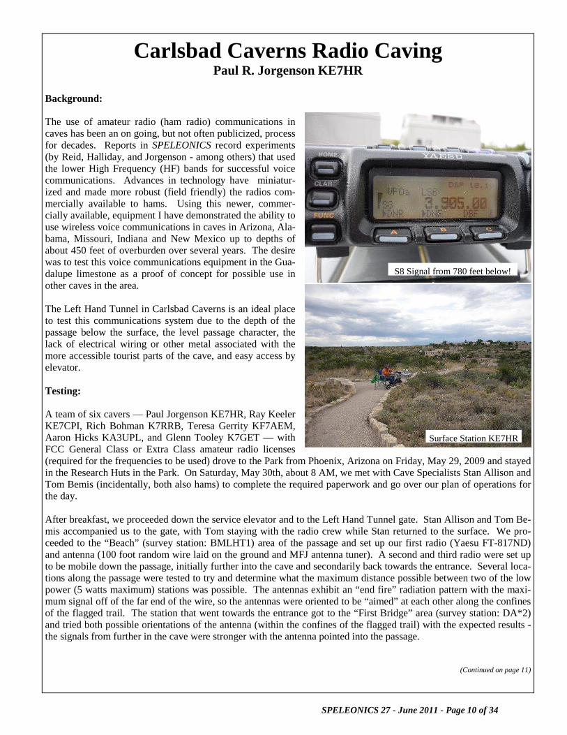
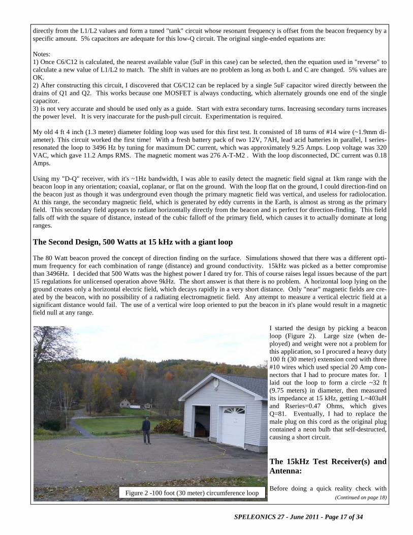
Background: The use of amateur radio (ham radio) communications in caves has been an on going, but not often publicized, process for decades. Reports in SPELEONICS record experiments (by Reid, Halliday, and Jorgenson - among others) that used the lower High Frequency (HF) bands for successful voice communications. Advances in technology have miniatur-ized and made more robust (field friendly) the radios com-mercially available to hams. Using this newer, commer-cially available, equipment I have demonstrated the ability to use wireless voice communications in caves in Arizona, Ala-bama, Missouri, Indiana and New Mexico up to depths of about 450 feet of overburden over several years. The desire was to test this voice communications equipment in the Gua-dalupe limestone as a proof of concept for possible use in other caves in the area. The Left Hand Tunnel in Carlsbad Caverns is an ideal place to test this communications system due to the depth of the passage below the surface, the level passage character, the lack of electrical wiring or other metal associated with the more accessible tourist parts of the cave, and easy access by elevator. Testing: A team of six cavers — Paul Jorgenson KE7HR, Ray Keeler KE7CPI, Rich Bohman K7RRB, Teresa Gerrity KF7AEM, Aaron Hicks KA3UPL, and Glenn Tooley K7GET — with FCC General Class or Extra Class amateur radio licenses (required for the frequencies to be used) drove to the Park from Phoenix, Arizona on Friday, May 29, 2009 and stayed in the Research Huts in the Park. On Saturday, May 30th, about 8 AM, we met with Cave Specialists Stan Allison and Tom Bemis (incidentally, both also hams) to complete the required paperwork and go over our plan of operations for the day. After breakfast, we proceeded down the service elevator and to the Left Hand Tunnel gate. Stan Allison and Tom Be-mis accompanied us to the gate, with Tom staying with the radio crew while Stan returned to the surface. We pro-ceeded to the “Beach” (survey station: BMLHT1) area of the passage and set up our first radio (Yaesu FT-817ND) and antenna (100 foot random wire laid on the ground and MFJ antenna tuner). A second and third radio were set up to be mobile down the passage, initially further into the cave and secondarily back towards the entrance. Several loca-tions along the passage were tested to try and determine what the maximum distance possible between two of the low power (5 watts maximum) stations was possible. The antennas exhibit an “end fire” radiation pattern with the maxi-mum signal off of the far end of the wire, so the antennas were oriented to be “aimed” at each other along the confines of the flagged trail. The station that went towards the entrance got to the “First Bridge” area (survey station: DA*2) and tried both possible orientations of the antenna (within the confines of the flagged trail) with the expected results - the signals from further in the cave were stronger with the antenna pointed into the passage.
(Continued on page 11)
S8 Signal from 780 feet below!
Surface Station KE7HR

SPELEONICS 27 - June 2011 - Page 11 of 34
Reliable SSB (single sideband) voice communications were established from the First Bridge area to the Beach and beyond to a point in the passage at survey station L30C1. The signal levels for these radios is given in “S” units, rang-ing from S0 (no indicated strength) to S9 (a very strong signal). Signal levels above S9 are in decibels above the S9 reading. The signals between the Beach and the L30C1 area were in the S2 range - very good, 100% communications quality. A rough distance survey with a Disto laser distance meter along the passage yielded an approximate 1100 feet of sepa-ration between the stations on each end of the passage. This appeared to be enough propagation of the radio signal through the rock to allow a surface to cave communications test. The team returned to the surface to set up the surface station and plan for the second trip, at about 12 PM. The Park has a linked repeater radio system on VHF that should allow communications from the surface through this system to the gate area of the Left Hand Tunnel. A Park radio was given to the surface team along with procedures for proper use to coordinate the start of the next experiment. The long wire antenna for the surface radio consisted of two 500 foot lengths of #14 wire that could be linked together to form one 1000 foot antenna and a MFJ tuner. The an-tenna was laid out along the Nature Trail south of the Caverns entrance. The Nature Trail conveniently very nearly aligns over the passage of the Left Hand Tunnel below. The wire was longer than the trail was straight, so the eastern end (far end from the radio) was bent to follow the trail. The surface radio was a Yaesu FT-857D which has addi-tional DSP filtering not available on the underground radios. This was somewhat important due to thunderstorms in the distance (estimated 20 to 30 miles at the closest) creating static and lightning discharges that were peaking up to a S8 signal strength.
(Continued from page 10)
(Continued on page 12)
Left Hand Tunnel passage character

SPELEONICS 27 - June 2011 - Page 12 of 34
Two underground teams went down the elevator, at about 1 PM. One team was going to go ahead to the Beach while the other team stayed near the Gate to be able to coordinate the start with the Park repeater radio. For some reason the Park VHF repeater was not functioning but SSB HF communications were established anyway. We were talking on a wireless radio through nearly 800 feet of rock with only 5 watts of radio power! The signals were at a bare minimum of usability with no indications on the S meter and interruptions by the thunderstorm static. An error in connecting the antenna tuner on the surface was found and corrected. The signals went up by nearly 100% in strength and intelligi-bility but still was not moving the S meter. We had achieved an acceptable level of communications to pass messages between the underground passage and the surface with a voice radio! The Gate team moved to the Beach and the Beach team went further into the cave to test at various locations along the passage as directed by the surface station. The team got as far as the end of the flagged trail (survey station: L32A1) where we still had acceptable communications with the surface and the Beach area station. The Beach station went back to near the First Bridge and established communications with the surface and the Trail End station before going back to the Beach for better signal strength. The surface antenna was switched between 500 and 1000 feet as the un-derground stations gave signal reports. Little difference was noted between the two lengths. The Trail End station started back towards the Beach stopping along the way to see if any better signal strength could be achieved with the surface. We had done all of the communications on the frequency of 3.905 MHz (75 meters) and tried a session at 1.975 MHz (160 meters) at survey station D349 with acceptable results. The antenna tuner in the cave was not able to achieve a good match at this frequency so we returned to 3.905 MHz to finish the experiments for the day. “The Beach” station tried a commercial antenna from MFJ which is a base loaded vertical and also used a 50 foot counterpoise (ground) which acts quite a bit like the random wire the other underground station was using, in effect the counterpoise wire has an “end fire” effect with the strongest signals off of the far end of the counterpoise. Various angles (direction and elevation) of the short vertical were tried with little to no effect on signal strength on either end of the path. As the “Trail End” station moved back towards the beach trying different locations, a zone of greatly enhanced signal strength was encountered near survey station D351. The signal strength jumped from not moving the S meter at all to a very robust S8 signal! This equates to a power increase of 35dB! Since we had such good signal strength at 5 watts, the power was reduced all the way to 1/2 watt and we still had a signal strength of S2 from the Left Hand Tunnel about 800 feet below the surface! Wow! A vertical orientation of the antenna underground was tried by letting the wire go down a vertical crack but no real enhancement of the signal was noted. Tom Bemis even made a contact with the surface from the S8 area. After doing a “happy dance”, the S8 station kept moving back towards the Beach and the signal went back to S0 by survey station L24. Back at the Beach, the experiment was over and the underground stations packed up and came up to the surface, just as distant stations were starting to use the frequency. The under-ground teams could not hear either the thunderstorm static or the distant stations. The surface antenna and station were packed up and brought back to the research huts, at about 5 PM. On Sunday, May 31st, we coordinated with Stan Allison (and returned the Park radio to him), at about 7:30 AM, for our reentry into the cave, before the tours started, to take photos of the character of the passage and attempt to see if there might be any clues for the zone of enhanced signal strength. There is a ceiling joint along the passage length but no other obvious physical indications of why there should be such a zone of higher signal strengths. We exited the cave about 9:30 AM, cleaned up the huts, finished the paperwork with Stan and then did a “tourist trip” down the natural entrance of Carlsbad Caverns. Even though we had all done this many times, the trip is always spe-cial. Reaching the elevators, we rode up again to the surface to depart for home. Conclusions: Using “off the shelf”, commercially available, amateur radio equipment we were able to establish acceptable SSB
(Continued from page 11)

SPELEONICS 27 - June 2011 - Page 13 of 34
voice communications along a significant length of the Left Hand Tunnel and to the surface from the underground. An area of greatly enhanced signal strength was noted. Theories about this zone need to take into account the possible antenna orientation of the surface to underground antenna, but not far from the enhanced zone the signal strength went
Study Area

SPELEONICS 27 - June 2011 - Page 14 of 34
down considerably with little change in antenna orientation. The possibility exists that there is an unknown void, probably a large one, between the Left Hand Tunnel and the surface above. The signal strength at the enhanced area is similar to caves in Arizona where we only had about 150 feet of overburden instead of nearly 800 feet. A future trip will be done to try and resolve this area more exactly. Distances achieved (straight line), as measured in the program Compass using the Park data file for Carlsbad Caverns: End of Trail (L32A1) to First Bridge (DA*2) = 1620 feet (.307 mile or 494 meters) End of Trail (L32A1) to Beach (BMLHT1) = 1250 feet (.237 mile or 381 meters) Depth achieved, with passage elevation derived from the Park data file for Carlsbad Caverns and the location of the Nature Trail on the USGS 1:24000 topographic map: Surface = 4380 feet Left Hand Tunnel = 3600 feet for a depth of 780 feet (.148 mile or 238 meters) Future: This amateur radio system should currently be capable of establishing voice communications to key areas of other caves in the Park such as the Lechuguilla EF Junction with about 550 feet of overburden. Licensing restrictions (current system requires a General Class or higher FCC amateur radio license) or possibly a National Park Service authorized frequency in the lower HF band could be used for deep communications in wild caves in the Park. Further testing in Carlsbad Caverns to try and determine the nature of the signal enhancement zone will be done at a future date. Different antennas and antenna configurations will be used to try and fine tune the system for even better performance. Also, when the Lake of the Clouds area is free from the bat restriction, a maximum depth trip will be undertaken.

SPELEONICS 27 - June 2011 - Page 15 of 34
Very High Power Radiobeacons And Long Range Direction Finding
Brian Pease, 3/29/11 Abstract This article describes the design and testing of 80 and 500 Watt high efficiency radiobeacons developed for direction-finding (homing) at 2-3km range on the Earth's surface using magnetic fields. Both are push-pull Class-E high-efficiency amplifier de-signs based directly on the author's existing single-ended class-E beacon. They could be employed underground for long range cave radiolocation and/or narrowband digital text communications use. Although intended for use with large high-Q tuned hori-zontal loops, this push-pull circuit can drive so-called Earth-current long wire antennas, with little additional filtering, exclusively for long range and/or deep digital communications use. There are no even harmonics. In a Spice simulation of the 80 Watt circuit with a resistive load (no series-tuned circuit) the 3rd and 5th harmonics are -16 and -25 dB down. Why build a high-power beacon? The author received an inquiry regarding the possibility of using a VLF magnetic field beacon on the Earth's surface to provide a homing signal that could be detected on the surface at 2-3 km range without generating a ground wave or skywave signal. A hori-zontal loop antenna, lying on the ground, for all practical purposes, generates only magnetic near fields. The primary magnetic field appears to be vertical everywhere (if the Earth is flat), and drops off approximately as 1/ distance cubed. This field sets up eddy currents in the somewhat electrically conducting Earth, which in turn produce a weaker secondary horizontal magnetic field that appears to come horizontally straight outward from the loop in all directions along the Earth's surface. This secondary mag-netic field drops off approximately as 1/distance squared, which means that at longer ranges (km) it becomes stronger than the primary field. The secondary field can be used for direction-finding at km ranges. This knowledge prompted me to do some simulations in the NEC-4 method of moments antenna simulation program. The results, although somewhat encouraging, turned out to be pessimistic (for once!). Real world conditions of uneven ground, varying con-ductivity, etc, improved the signal strength at long range when compared to theory on a flat Earth, at least on my hilly test range. With the possibility of some paid work in the future, I decided to cobble together a beacon with as much power as I could with what I had on hand. I chose 3496 Hz because I could use an existing beacon loop antenna and my narrow band DQ receiver. The first Design, 80 Watts push-pull at 3496 Hz My current single-ended Class-E beacon design, for which I have made circuit boards, is documented on my website: http://radiolocation.tripod.com/NewDQandBeaconFiles/2008DQboards/NotesOnThe2008_DQReceiverBoards.html In Speleonics 25, pgs 11-12, http://www.caves.org/section/commelect/splncs/splncs25.pdf , I gave design equations for the sin-gle-ended circuit and described the use of the free LT Spice circuit analysis program for simulation. I knew that the single-ended design was capable of more power, perhaps 25-30 Watts, so I decided to combine two of these circuits, with one PC board (the Master) containing the 3496 Hz oscillator. The Master drove the second board (the Slave) 180 degrees out of phase, forming a push-pull circuit. The two outputs are added in series, with the output voltage looking like a slightly stepped sine wave. The left half of Figure 1 is one of my single-ended Class-E beacon circuits, unmodified except for the number of turns on the sec-ondary of T1 which sets the power level. T1 is the same CM270125 toroid core of MPP material (from CWS Bytemark) that I supply with my beacon boards. The right half of the schematic is a modified Class-E beacon board with only a few parts installed. The power MOSFET with its output circuit is unchanged except that it is driven from an inverter that is part of the 74HC4060. It is necessary that Q2 turn off when Q1 is turned on by the 3496 Hz square wave drive. The secondary output of T2 (connects to Q2) is 180 degrees out of phase with T1, giving the desired push-pull output. The TO-220 style MOSFETs are secured to copper pads on the boards without heat sinks. The single-ended design equations found in Speleonics 25 can be used to derive the values of C6/C12 and the inductance (called L1/L2 here) of the primaries of T1/T2. The actual values of L1/L2 are not critical, but it is best to calculate them assuming that each half of the push-pull circuit provides 1/2 of the output power, 40 Watts in this case. The values of C6/C12 are calculated
(Continued on page 16)

SPELEONICS 27 - June 2011 - Page 16 of 34
are Henries
= battery, volts
= desired output power, Watts. For a push-pull circuit, P is 1/2 of the desired output power. are Farads
W h e r e = frequency in Hz
= series-resonant load that, when placed directly across L1 or L2, will cause the single-ended circuit to draw the de-sign power P. A secondary winding is used to translate the actual resonant load resistance to this value.
(Continued from page 15)
Figure 1—80 Watt Beacon
SPELEONICS 27 - June 2011 - Page 17 of 34
directly from the L1/L2 values and form a tuned "tank" circuit whose resonant frequency is offset from the beacon frequency by a specific amount. 5% capacitors are adequate for this low-Q circuit. The original single-ended equations are: Notes: 1) Once C6/C12 is calculated, the nearest available value (5uF in this case) can be selected, then the equation used in "reverse" to calculate a new value of L1/L2 to match. The shift in values are no problem as long as both L and C are changed. 5% values are OK. 2) After constructing this circuit, I discovered that C6/C12 can be replaced by a single 5uF capacitor wired directly between the drains of Q1 and Q2. This works because one MOSFET is always conducting, which alternately grounds one end of the single capacitor. 3) is not very accurate and should be used only as a guide. Start with extra secondary turns. Increasing secondary turns increases the power level. It is very inaccurate for the push-pull circuit. Experimentation is required. My old 4 ft 4 inch (1.3 meter) diameter folding loop was used for this first test. It consisted of 18 turns of #14 wire (~1.9mm di-ameter). This circuit worked the first time! With a fresh battery pack of two 12V, 7AH, lead acid batteries in parallel, I series-resonated the loop to 3496 Hz by tuning for maximum DC current, which was approximately 9.25 Amps. Loop voltage was 320 VAC, which gave 11.2 Amps RMS. The magnetic moment was 276 A-T-M2 . With the loop disconnected, DC current was 0.18 Amps. Using my "D-Q" receiver, with it's ~1Hz bandwidth, I was able to easily detect the magnetic field signal at 1km range with the beacon loop in any orientation; coaxial, coplanar, or flat on the ground. With the loop flat on the ground, I could direction-find on the beacon just as though it was underground even though the primary magnetic field was vertical, and useless for radiolocation. At this range, the secondary magnetic field, which is generated by eddy currents in the Earth, is almost as strong as the primary field. This secondary field appears to radiate horizontally directly from the beacon and is perfect for direction-finding. This field falls off with the square of distance, instead of the cubic falloff of the primary field, which causes it to actually dominate at long ranges. The Second Design, 500 Watts at 15 kHz with a giant loop The 80 Watt beacon proved the concept of direction finding on the surface. Simulations showed that there was a different opti-mum frequency for each combination of range (distance) and ground conductivity. 15kHz was picked as a better compromise than 3496Hz. I decided that 500 Watts was the highest power I dared try for. This of course raises legal issues because of the part 15 regulations for unlicensed operation above 9kHz. The short answer is that there is no problem. A horizontal loop lying on the ground creates only a horizontal electric field, which decays rapidly in a very short distance. Only "near" magnetic fields are cre-ated by the beacon, with no possibility of a radiating electromagnetic field. Any attempt to measure a vertical electric field at a significant distance would fail. The use of a vertical wire loop oriented to put the beacon in it's plane would result in a magnetic field null at any range.
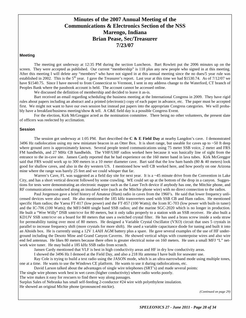
I started the design by picking a beacon loop (Figure 2). Large size (when de-ployed) and weight were not a problem for this application, so I procured a heavy duty 100 ft (30 meter) extension cord with three #10 wires which used special 20 Amp con-nectors that I had to procure mates for. I laid out the loop to form a circle ~32 ft (9.75 meters) in diameter, then measured its impedance at 15 kHz, getting L=403uH and Rseries=0.47 Ohms, which gives Q=81. Eventually, I had to replace the male plug on this cord as the original plug contained a neon bulb that self-destructed, causing a short circuit. The 15kHz Test Receiver(s) and Antenna: Before doing a quick reality check with
(Continued on page 18) Figure 2 -100 foot (30 meter) circumference loop

SPELEONICS 27 - June 2011 - Page 18 of 34
this transmit loop, I had to assemble a test receiver. I had a Rycom 3121B Selective Level Meter (Figure 3) with a 250 Hz bandwidth and a direct readout of signal strength, with no AGC, but it was not very sensitive. I needed a preamp and decided to use one stage of the venerable LM833 dual bipolar op-amp, which is designed specifically for low noise audio frequency use. I decided to use a non-inverting circuit with its infinite input impedance that would not load the parallel-tuned receiv-ing loop antenna. The preamp schematic is shown in Figure 4, with the parts list in the Appendix. I constructed it as a dual preamp to also allow testing of dual x-y rod antennas with a sound card receiver that had I/Q inputs. Theoretical gain is 40dB, with enough sensitivity to detect the thermal noise from the antennas, which in turn was overridden by atmospheric noise during my tests. The optimum antenna impedance for the LM833 for best sensi-tivity is 6857 Ohms but anything from 1/2 to twice this value will work well. Atmospheric noise levels actually peak near 15kHz, which allowed me to use a tiny 4" (10.2 cm) long 1/2" (1.27 cm) dia ferrite rod of type 61 (Ui=125) material. For one test antenna I used 140 turns of 220/46 Litz wire (220 strands of #46 wire) wound in 2 layers over most of the length of the rod. This gave L=1.04mH with Q=165 and resonated impedance of 16.1k Ohms which is a bit high but I went with it. The noise level of this tuned loop is 2.0 nA/meter, well below atmospheric noise. As a backup (and experiment), I downloaded a software defined sound card VLF receiver, which I installed on my netbook. This was "SD Radio" by Alberto, I2PHD, http://www.sdradio.eu/sdradio a very simple and robust program that provides both a spectrum analyzer display and audio output up to 20kHz. In the SSB mode, the bandwidth can be narrowed to ~100Hz. My pre-amp was able to drive the mike input of the netbook's sound card directly. S/N ratio is directly displayed. The program actually had both I and Q inputs, which created an omindirectional pattern from a pair of "crossed" loop antennas. The only drawbacks I found were: 1) the netbook had to be placed at least 10 feet from the receive antenna to avoid introducing computer noise and 2) The program had very effective AGC that made direction-finding using the audio difficult. Never the less, it effectively received signals anywhere that the Rycom could. A second program I tested was the Sound Card Oscilloscope by Christian Zeitnitz, http://www.zeitnitz.de/Christian/scope_en?mid=1022&PHPSESSID=iarotj9ooavm86l58165ku0ll0 . This program provides a 2-channel 20kHz oscilloscope that can also be used in x-y mode, with a brick wall filter allowing bandwidths down to 2HZ. Signals in the 2 channels can be added, subtracted, or multiplied. It includes cursors to measure amplitude, time, and frequency. It also has a signal generator for sine, square, trian-gle, and sawtooth waveforms which has two outputs with adjustable phase relationship. This program has great potential but I found 2 drawbacks: 1) there is no way to get a heterodyned audio output like the SD Radio and 2) the square wave had too much distortion and duty cycle error at 15kHz to be useful as a driver for the 500 Watt amplifier. The 15kHz Reality Check: I series-resonated the 100 ft (30 meter) circumference beacon loop with 0.2754uF, using high-voltage polypropylene caps. I then used a CWS Bytemark CM270125 toroid of MPP material to convert the 0.47 Ohm loop impedance to 4 Ohms, using 12Turns/37Turns. I used a 50 Watt car stereo amplifier in 4 Ohm bridged mode, driven with a 15.000kHz sine wave source, to generate 8 Amps of signal current in the loop, which is a magnetic moment of 1775 Amp-Turns-Meters squared. At 1km range, using the Rycom receiver, the signal was just above the atmospheric noise level, which was very good considering that the 250 Hz bandwidth has 24dB more atmospheric noise than the 1 Hz bandwidth used for the original 3496 Hz test. I could direction-find (by ear) at this range. I decided to build a 500 Watt beacon amplifier. The 500 Watt 15kHz Push-Pull Class-E Amplifier:
(Continued from page 17)
Figure 3

SPELEONICS 27 - June 2011 - Page 19 of 34
The basic design is the same as the 3496 Hz push-pull amplifier, with additional circuitry to pro-tect the MOSFETs (Q1 and Q2) from destruction. The schematic is shown in Figure 5, with the parts list in the Appendix. To save space and cost, C2 serves as the "tank" tuning capacitor for both MOSFETs. This is possible because Q1 is ON (grounding C2) when Q2 is OFF, and vice versa. The MOSFET driver U3 per-forms several functions. It has a high impedance input with Schmidt trigger action for very fast switching and inverting/non-inverting low impedance outputs with 4 Amp drive to rapidly switch the push-pull MOSFET inputs. The Enable inputs are used to prevent any MOSFET gate input unless sufficient DC supply voltage is available to switch it full ON. The "RF" input is a 5V p-p square wave dc referenced to ground. If the source is capaci-tor-coupled, add a 1N914 diode across R10, with anode to ground. It is critically important that the duty cycle be exactly 50% to prevent large current transients in the MOSFETs that will destroy them in minutes.
The best simple signal source is a 74HC4060 oscillator/binary divider with a common 7.68MHz clock crystal running on 5VDC. 9 binary stages gives 15.000kHz with a precise 50% duty cycle. Simple "free-running" generators could be used by dividing a 30kHz output frequency in half with a flip-flop. For my actual testing, I acquired a Protek Direct Digital Synthesis (DDS) wave-form generator which I set to produce a 15.000kHz square wave with a precise 50% duty cycle that was keyed on for ~5 sec/off for ~5 sec. The on/off timing is synchronized with the square wave, eliminating any possibility of transients. The 36 Volt supply was chosen to allow operation from three 12V deep cycle batteries in series, but for actual testing I opted to use a 28.5VDC power supply that could deliver up to 100 Amps from 240 VAC. The power input level with this supply is about 370 Watts. At this power level, even a brief (milliseconds) excursion into the linear region during power-up can destroy the MOSFETs. I added a latching relay circuit that disables the driver U3 and shorts the gates of Q1 and Q2 to ground when the power supply is first connected. Pressing SW1 latches the amplifier ON. If the battery voltage becomes too low for proper gate drive, or there is a momentary power failure with an AC supply, the relay drops out to save the transistors. I included a timer circuit U2 to cycle the beacon on-off every ~10 sec with a 20-100% duty cycle when used with a continuous square wave input. There is a slight risk using this timer because it is not synchronized with the 15kHz square wave which will alter the duty cycle of the first and last pulses of each ON period. I experienced no failures from this. After an embarrassing failure due to overheating, I added a cooling fan. Even though efficiency is high, >90%, there is still 40-50 Watts of heat to dissipate, much of which appears to be due to the undersize wires used in the toroid transformers, plus some core
(Continued on page 20)
Figure 4—Preamp Schematic

SPELEONICS 27 - June 2011 - Page 20 of 34
(Continued from page 19)
(Continued on page 21)
Figure 5—500 Watt 15kHz Beacon

SPELEONICS 27 - June 2011 - Page 21 of 34
loss. Only a few Watts are lost in the MOSFETs. Although not tested, with the fan it will likely operate continuously without overheating. The simulated raw output voltage waveform (between the 500 Watt poles of SW5) is shown in Figure 6, with the amplifier run-ning 370 Watts input from a 28.5V supply. The stepped sine wave has no second harmonic and the third harmonic is -14dB. The actual resonant loop current of ~27Amps RMS has a third harmonic of -48dB. Loop (and total C3 voltage) is ~1000 volts RMS. The magnetic moment is ~6000 Amp-Turns-meter squared! Figure 7 is the prototype 500 Watt beacon amplifier. The lid is raised on spacers to provide an outlet for the cooling air. Note that no expense was spared on the labels! The Field Test: I set up the loop on a gravel driveway next to my garage where a 220 volt outlet was available. I operated my Protek signal source from a true RMS inverter in my motorhome, since a momentary interruption of AC power would change the Protek settings and possibly damage the amplifier. There was no problem detecting and direction-finding on the secondary magnetic field at 2.0km range in an area far from pipes and wires, using the little 4" (10.2 cm) rod antenna/preamp and the Rycom's 250Hz bandwidth. With a narrowband receiver, range should be 3km or more. Conclusions: • It is relatively easy to construct a very high power radiobeacon. For portable use, a low on/off duty cycle mode should be
used to save the battery. • This non-linear amplifier design is compatible with FM voice or any one-tone-at-a-time digital text mode such as CW, RTTY,
FSK31, JASON, MFSK, etc. There is no legal issue when operating below 9kHz (in the USA), and should be no issues at higher frequencies when used with a horizontal tuned loop since it should be able to pass the Part 15 tests for unlicensed op-eration. Just don't cause interference to licensed operators (or anyone else!).
• These tests show how the secondary magnetic field allows cave radiolocation to work so well at ranges on the surface many times the depth of the beacon.
(Continued from page 20)
Figure 6 Raw output voltage waveform of the 500 Watt Amplifier
Figure 7—Prototype 500 Watt Beacon Amplifier

SPELEONICS 27 - June 2011 - Page 22 of 34
APPENDIX—Parts List for 500 Watt 15 kHz Class-E Beacon
and Dual low noise antenna preamp 10/5/10
Part Description Part #, “ND” is DigiKey Each Total
R1 240 Ohm Carbon film, ¼ Watt, 5% 240QBK-ND
R2 2K “ 2.0KQBK-ND
R9 100K “ 100KQBK-ND
R4,R8 1K “ 1.0KQBK-ND
R6 240K “ 240KQBK-ND
R7 1Meg linear pot Mouser 31VC601-F
R14A,B 100k dual linear pot Mouser 31VW501-F
R3,R5 3.3k 3.3KQBK-ND
C1, C5 0.1uF 50V ceramic, 0.1” spacing BC1084CT-ND
C2A 0.47uF 450V hi-Amp polypro, 10mm sp P14202-ND /4
C3 0.15uF 3000VDC hi-Amp axial polypro 1.2mm dia lead, 46mm L, 27mm dia
338-1188-ND /2
C3 0.10uF 3000VDC 1.2mm dia lead, 46mm L, 22.5mm dia
338-1187-ND /2
C3 .01uF 3000VDC 1.0mm dia lead, 34mm L, 11.5mm dia
338-1183-ND /2
C3 .015uF 3000VDC 1.0mm dia lead, 34mm L, 13.5mm dia
338-1184-ND /4
C4 100uF 50V, ELEC,8 dia, 12H, 3.5mm sp 565-2005-ND
C6 10uF 63V, 9mmW, 18mmL, 0.6” spacing Mouser 5989-100V10.0-F
C7,C12, .01uF 50V ceramic, 0.1” spacing BC1078CT-ND
C9 1uF 59V ceramic, 0.2” spacing BC1168CT-ND
C11,C15 1000pF 50V COG ceramic BC1025CT-ND /10
C13,C17 50pF 50V COG ceramic /2
C19,C20 0.11uF 63V polypro tuning cap BC2055-ND /10
C19,C20 .047uF 63V polypro tuning cap BC2068-ND /10
C19,C20 1000pF 63V polyester tuning cap 399-5419-ND /10
C19,C20 .01uF 63V polyester tuning cap 399-5437-ND /10
C19,C20 4700pF 63V polyester tuning cap 399-5417-ND /10
D1,D4,D5 1N914/4148 diode 1N4148TACT-ND /15
D2 12V 1W zener diode 1N5242BFSCT-ND
D3 12V panel mount Red LED MPJ 17303-LE
D6 6 Amp 100V rectifier MPJ 5219-DI
D11 12V panel mount Green LED MPJ 17303-LE
D20,D21 3mm diffused Green LED P564-ND /2

SPELEONICS 27 - June 2011 - Page 23 of 34
F1 30 Amp auto fuse MPJ 3619-FU
Holder Heavy duty inline fuseholder MPJ 8879-FH /2
J1,J6,J7 BNC female panel jack. MPJ 0507-RC /3
J2 Male 120VAC plug local
J3 Female 120VAC socket local
J4,J5 30 Amp Power Pole conn, 4 pieces On hand /4
J8 1/8” stereo phone jack Mouser 161-3402-E
Loop 100 foot extension cord, 3 cond #10 wire Local
M1 30 Amp DC analog meter with ext shunt MPJ 17679-ME
Q1,Q2 IRFI4321PBF MOSFET (150V) IRFI4321PBF-ND /2
Q1,Q2 IRFB260NPBF (200V, higher Ron) IRFB260NPBF-ND /2
RL1 Omron G5V-2 style 24VDC, 1600 Ohms Z772-ND
SW1A Momentary ON red push button (norm OFF) MPJ 5019-SW
SW1B Momentary ON blk push button (norm OFF) MPJ 5020-SW
SW2A,B DPDT mini toggle switch MPJ 5011-SW /2
U1 LM317L voltage regulator LM317LZ-ND
U2 555 timer MPJ 2350-IC /2
U3 MCP14E5-E/P dual mosfet driver, DIP MCP14E5-E/P-ND /2
U4A,B LM833 dual op amp, DIP 497-1598-5-ND /2
DIP sock- 8-pin ED90032-ND /3
Dip socket 16-pin ED3316-ND /1
Heat sink TO-220 10W vertical screw mount Aavid 1.65W x 1.0TK x 1.5” H
HS276-ND /2
Case Gray plastic Elec box, 6x6x4” high Lowes local
Case 4x3x1.6” plastic box MPJ 15523-BX
Cable 5 ft BNC male-BNC male (for preamps/ants) 290-1013-ND /2
Cable 12 ft shielded stereo 1/8” phone cable MPJ 11292-CB /1
Batteries (2) 9V local
Holder (2) 9V battery holders 1295K-ND /2
Wire #14 magnet wire MPJ 7258-WI
Wire #16 magnet wire MPJ 7257-WI
MPJ is Marlin P Jones, mpja.com

SPELEONICS 27 - June 2011 - Page 24 of 34
The TP-6N Field Telephone By Jansen Cardy
A brief history lesson. As most of you know, military field telephones have been standard cave rescue communication equipment in the US for many decades. Field phones are relatively robust, cheap, and somewhat easy to obtain in surplus quantities. Other custom-built options certainly have advan-tages but producing a standard, reliable design in quantity while being cost-effective is not so easy. Of course this doesn’t stop people experi-menting, as shown in many fine Speleonics articles! Over the years many rescue organizations, grottos and individual cavers have stockpiled field phones and military WD-1 wire for rescue contingencies and project use. But these phones – like the old EE-8, TA-312 and TA-1 – date back to the 1940’s and 50’s and those used in caves are especially showing their age. They are notoriously heavy and awkward to carry around, voice quality is often poor, and they can experience sudden failures. However given their widespread use and popularity for cave rescue, and being central to the nationally standard-ized training provided by NCRC, trying to change the system is not an easy process. For a couple of years I tinkered with ideas to improve upon what we had, like adding an amplified microphone to the sound-powered TA-1. It was fun but I didn’t get very far. Then in the fall of 2008, we caught a break. A surplus dealer in the US adver-tised some interesting-looking European field phones at a reasonable price. I purchased some to evaluate, and was quickly im-pressed by their design and ability to interface directly with existing US field phones and wire. Excellent! Being an NCRC instructor with a background in military communications I advised NCRC to purchase some of these phones to trial. Despite some skepticism about foreign equipment and possible supply and repair problems, the phones were declared a suc-cess and the good news spread to other organizations. Demand quickly exceeded supply, so I decided to track down a new source directly from Europe. Almost 3 years later, there are now over 200 of these phones in the hands of cavers and rescue-related or-ganizations across the US. A new twist on old technology. Officially the TP-6N is a Norwegian-built felttelefon (field telephone) produced for the Norwegian and Dutch armed forces. The Dutch refer to this veldtelefoon as the TA4881. It was designed in the early 1970’s by Electrisk Bureau in Billingstad, Norway, and won an award for design excellence in 1973. The TP-6N weighs a little less than 3 lbs and measures about 10 x 7 x 2 inches in its carry pouch. Despite being very robust and waterproof it’s only a third the size and weight of the old US TA-312. Voice clarity and volume is excellent, and an efficient electronic ringer is used to signal other phones. A call light and handset buzzer indi-cates incoming calls and also allows an operator to identify open circuit and shorted telephone line
(Continued on page 25)

SPELEONICS 27 - June 2011 - Page 25 of 34
conditions. The TP-6N can be powered by 3 D cells, or by 3 AA cells with the use of a custom battery adapter. This innovative battery tube was designed and produced by Ken Anderson, a fellow rescue communications experi-menter. We reasoned that AA cells are a more logical power source than D cells because they are smaller, lighter, cheaper, and easier for cavers to carry spares. Modern alkaline, lithium and NiMH AA cells are easily suffi-cient to power the phone. And if necessary the phone can be used without batteries in sound-powered mode but with no outgoing ringer. For users familiar with older model field phones, there are a few minor considerations you should be aware of with these phones. First, the origi-nal military configuration for the TP-6N handset switch is “push to talk AND listen.” This was intended to isolate the earphone from the line so it wouldn’t act as a bug allowing people to listen in on nearby conversations.
Pressing the talk button just to listen is somewhat counter-intuitive and frustrating to rescue users, but fortunately the switch is easily modified by simply swapping a wire over inside the handset. Second, the TP-6N electronic ringer will alert numerous other TP-6N phones at one time but can sometimes fail to sound the me-chanical clacker on older field phones because of higher resistance. If ringer signaling is a priority, try to limit the number of older field phones connected to the same line. Voice communication between old and new phones is not affected. And third, the line terminals on the TP-6N are designed for connecting the phone to the END of a length of wire. This differs from open-sided terminals on many other field phones. The easy fix is to attach a pair of leads to the line terminals with alligator clips at the ends. This will allow the TP-6N to be clipped in anywhere along the phone line, after carefully shaving a little insulation off each WD-1 conductor at spaced intervals. In the short time since it was introduced to the US caving community the TP-6N has been used in dozens of training events and a significant number of actual rescues, all with rave reviews. During one callout the AA battery adapters were left behind and no D cells were available. Rescuers had to use the phone in sound-powered mode, and found they could easily communicate over 1000 feet of wire. Even teams with their own cave radios use the field phones to supplement their communication requirements. There have been more subtle changes too, including some attitudes among cave rescuers. After dragging a 10 lb football-sized TA-312 through a cave, people don’t complain so much about the little 3 lb TP-6N. Smaller size and greater reliability means less frustration, less rough handling, and no more trying to drop-kick equipment into submission. A clear and easy to operate phone also makes rescue managers more likely to talk to each other directly without relaying through a telephone opera-tor. Ultimately, this helps cut down on errors and allows information to flow more efficiently. Many organizations initially adopted the TP-6N to partner with their older field phones, but most now have them fulfilling the cave commu-nication role completely. Field telephones may not be the perfect solu-tion for cave rescue, but at least here in the US they seem to fill the niche. Perhaps in future there will be a standardized all-wireless solution which is compact, reliable, durable, easily operated, and cheap. But for around $50 per phone and a little more for a spool of wire, the TP-6N is proving to be a viable option for many users – at least for now. For those interested in specs, the TP-6N has a frequency range of 300 to 3400 Hz and a nominal impedance of 600 ohms. Battery voltage is 4.5 volts, and current consumption is 7.5 mA for voice communication and 430 mA for the call ringer. The ringer frequency is 25 Hz, and call volt-age is nominally 60 volts under load. Communication range is 22 miles over WD-1 wire, temperature tolerance is -40F to +130F, and the unit is resistant to EMP. More specifications and details can be found online at http://tp6n.blogspot.com/
(Continued from page 24)

SPELEONICS 27 - June 2011 - Page 26 of 34
Simple Phone Line Amplifier By Jansen Cardy
A small amplified speaker attached to the field telephone system can be a useful tool for Incident Command and other locations during a rescue. It allows personnel to receive information without constantly holding a phone to the ear. With this version, headphones can be connected and at the flip of a switch the speaker can be muted for privacy. This project requires a $15 Mini Audio Amplifier (Radio Shack part number 277-1008). The amplifier is small and light – not much larger than a pack of cigarettes – and is powered by a 9 volt battery. It's de-signed for a microphone input so some modification is needed to inter-face with field telephones. The photos show the completed project as well as the circuit board before and after modification, and a close-up of the mute switch installed next to the battery. Note the three highlighted areas in the photo of the modified circuit board.
In the left highlighted area, I used a simple T-pad circuit to lower the input level and a capacitor to protect the amplifier from high voltage ringer current. This is wired in series with the tip of the input jack as shown in the circuit diagram below. The external speaker (or headphones) jack is shown in the cen-ter highlighted area. It incorporates normally-closed switch contacts to disconnect the main speaker when a plug is inserted. I soldered a bridge across these contacts on the circuit board side (not visible in the photo) to enable the speaker to continue operating independently even when headphones are connected. In the right highlighted area I added a mute switch in series with the speaker. Please note this does not turn off the am-plifier, it only silences the built-in speaker. Be sure to ad-just the volume control to match the type of phones con-nected to the line. Keep the volume setting low when lis-tening to battery-powered phones, and raise it for sound-powered phones. If a phone is located nearby, consider muting the speaker while transmitting. This will avoid an-noying feedback distortion.
The components and their Radio Shack part numbers are listed below: - C1: 1.0µF 250V Metal-Film Capacitor [272-1055] - R1 and R2: 100k-Ohm 1/2 Watt Carbon Film Resistors [271-1131] - R3: 470k-Ohm 1/2 Watt Carbon Film Resistor [271-1133] - this value works well matching the amplifier with most field phones. Substituting for a lower resistance will lessen feedback distortion when using battery pow-ered phones nearby, but will make the amplifier less sensitive to lower audio levels (sound powered phones). - J1: The 1/8 inch mono audio input jack on the amplifier - interrupt the circuit at this point by lifting the terminal which connects the tip of the jack to the circuit board. Apply solder, lift it out of the board, bend it flat, and solder the capacitor and T-pad circuit in series as shown in the dia-gram. - Single Pole Single Throw Micromini On-Off Toggle Switch [275-624] (not shown in diagram) - acts as a mute switch by disconnecting the speaker. Wire in series with one of the speaker terminals, and install the switch carefully so as not to obstruct the battery. I recommend switching down to mute. - My telephone line connecting lead is made from about 2 feet of lamp cord with a pair of Mini Alligator Clips [270-1545] on one end, and a 1/8 inch Mono Phone Plug [274-286] on the other.

SPELEONICS 27 - June 2011 - Page 27 of 34
Modifying the classic phone patch By Jansen Cardy
Like so many other caver/rescuer/hams, once I discovered the old classic Frank Reid phone patch design I just had to build one for myself. My version was for a Yaesu handheld, but with no VOX feature the push-to-talk operation was rather awkward. It also occurred to me that trying to teach cave rescue students to use this equipment was largely a waste of time for those who have no connection or interest in amateur radio. With technology improving in leaps and bounds over the last decade or so, port-able radios are no longer mostly in the realm of ham operators and CB users. While amateur radio will always be a valuable resource, Family Radio Service handhelds are now very common, cheap, and popular with outdoor enthusiasts and cavers. However they are somewhat limited in range, very non-private, and easily interfered with. Newer 900MHz TriSquare eXRS units are also rather limited in
range, but offer very private frequency-hopping technology at a mini-mal cost. Anybody can legally operate consumer radios like these, and most come with built-in VOX. Fire/rescue handhelds and other commercial units are everywhere too, utilizing VHF, UHF, trunking, data and more. Interoperability be-tween agencies is commonplace. Virtually every rescue worker now carries a radio and is directly connected to the flow of information – at least above ground. In addition many people own cell phones and network coverage is constantly improving, even in caving areas. It’s not so far-fetched for the field telephone line to come out of the cave and connect to a cell phone so the medic can speak directly with a specialist at the hospital. But what does all this have to do with the phone patch? Well, many of these devices have a single combined mic/ear socket with a common ground instead of the old speaker/mic configuration using two sepa-rate pairs. So the old design needed a little tweaking. I added a 10.0µF non-polarized electrolytic capacitor to allow audio coupling between the 8 ohm and 1 k ohm transformer windings, while restrict-ing DC current flow. I also replaced the 5 k ohm audio taper potenti-ometer with a tiny 100 k ohm audio trimmer, which allows a wider range of adjustment to allow for mic and VOX levels in different ra-dios. I replaced the momentary push switch with a latching rocker, allow-ing a person to select between receive-only and automatic transmit
via the built-in VOX in the radio. When making a cell phone call (which is of course full-duplex) the phone patch would be switched on for the entire duration. The original design suggested binding posts to connect to the telephone wire, but I find a short length of heavy duty lamp cord with alligator clips to be more durable and convenient. On the other side, I attached a short heavy duty audio cord with molded stereo socket. Then I can select the audio adapter cord to match, depending on which device I’m connecting to. The cables are secured inside the box using plastic cable ties and sealed with AquaSeal adhesive sealant. The components and their Radio Shack part numbers are listed below: - C1: 1.0µF 250V Metal-Film Capacitor [272-1055] - C2: 10.0µF 50V Axial-Lead Non-Polarized Electrolytic Capacitor [272-999] - T1 and T2: Audio Output Transformers with 1 k ohm primary and 8 ohm secondary [273-1380] - VR1: 100K-Ohm Horizontal-Style Trimmer (Variable Resistor/Potentiometer) [271-284] - SW1: Single Pole Single Throw On-Off Rocker Switch [275-694] - J1: 3.5mm (1/8 inch) Stereo Jack Cable [42-2458] - or you can substitute a plug which connects directly to your specific radio. Be sure to determine the correct pin connections! - Mini Alligator Clips [270-1545]
Editor Note: The circuit may present a larger than normal load to the phone net-work. A small resistor (200-500 ohms) in series with the capacitor on the input of the transformer should limit the current and thus the volt-age drop on the network. EXPERIMENT!
SPELEONICS 27 - June 2011 - Page 28 of 34
Minutes of the 2007 Annual Meeting of the
Communications & Electronics Section of the NSS Marengo, Indiana
Brian Pease, Sec/Treasurer 7/23/07
Meeting
The meeting got underway at 12:35 PM during the section Luncheon. Bart Rowlett put the 2006 minutes up on the screen. They were accepted as published. Our current “membership” is 118 plus any new people who signed in at this meeting. After this meeting I will delete any “members” who have not signed in at this annual meeting since the no dues/5 year rule was established in 2002. This is the 5th year. I gave the Treasurer’s report. Last year at this time we had $1530.74. As of 7/12/07 we have $1540.75. Since I have moved to from Connecticut to Vermont, I sent in my address change to the Waterford, CT branch of Peoples Bank where the passbook account is held. The account cannot be accessed online. We discussed the definition of membership and decided to leave it as-is. Bart received an email regarding scheduling the business meeting at the International Congress in 2009. They have rigid rules about papers including an abstract and a printed (electronic) copy of each paper in advance, etc. The paper must be accepted first. We might not want to have our own session but instead put papers into the appropriate Congress categories. We will proba-bly have a breakfast/business meeting/show & tell. A C&E field day is a possible Congress Event. For the election, Kirk McGreggor acted as the nomination committee. There being no other volunteers, the present slate of officers was reelected by acclimation.
Session
The session got underway at 1:05 PM. Bart described the C & E Field Day at nearby Langdon’s cave. I demonstrated 3496 Hz radiolocation using my new miniature beacon in an Otter Box. It is short range, but useable for caves up to ~50 ft deep where ground zero is approximately known. Several people tested communications using 75 meter SSB voice, 2 meter and FRS FM handhelds, and 27 MHz CB handhelds. The VHF/UHF radios worked here because it was basically line of sight from the entrance to the in-cave site. Jansen Cardy reported that he had experience on the 160 meter band in lava tubes. Kirk McGreggor said that FRS would work up to 300 meters in a 10 meter diameter cave. Bart said that the low ham bands (80 & 40 meters) look good for shallow caves, and also in the dry western US. I mentioned how well CB worked here, and how poorly on one Arizona mine where the range was barely 25 feet and we could whisper that far. Warren’s Cave, FL was suggested as a field day site for next year. It is a ~45 minute drive from the Convention in Lake City, and has a short vertical descent followed by some crawling. WE could set up at the bottom of the drop in a canyon. Sugges-tions for tests were demonstrating an electronic mapper such as the Laser Tech device if anybody has one, the Mitchie phone, and RF communications conducted along an insulated wire (such as the Mitchie phone wire) with no direct connection to the radios. Paul Jorgenson gave a brief history of Amateur (Ham) radio in caves from the 1960’s. He said that lower frequency unli-censed devices were also used. He also mentioned the 185 kHz transverters used with SSB CB and Ham radios. He mentioned specific Ham radios; the Yaesu FT-817 (low power) and the FT-857 (100 Watts); the Icom IC-703 (low power with built-in tuner) and the IC-706 (100 Watts); the MFJ-9400 single band SSB radios; and the marine SGC-2020 which is no longer in production. He built a “Wee Willy” DSB xmtr/rcvr for 80 meters, but it only talks properly to a station with an SSB receiver. He also built a KD1JV SSB xmtr/rcvr on a board for 80 meters that uses a switched crystal filter. He has used a brass screw inside a soda straw for permeability tuning over most of 80 meters. He designed a Variable Crystal Oscillator (VXO) circuit that uses 5 crystals in parallel to increase frequency shift (more crystals for more shift). He used a variable capacitance diode for tuning and built it into an Altoids box. He is currently using a 12V 1.4AH AGM battery plus a spare. He gave several examples of the use of HF under-ground including the Desoto Mine and Grand Canyon Caverns. He showed vertical whips with counterpoise wires and also wire end fed antennas. He likes 80 meters because there often is greater electrical noise on 160 meters. He uses a small MFJ “L” net-work wire tuner. He may build a 185 kHz SSB radio from scratch. Jansen Cardy mentioned that VLF is best in high conductivity areas and HF in dry low conductivity areas.
I showed the 3496 Hz I demoed at the Field Day, and also a 218 Hz antenna I have built for seawater use. Ray Cole is trying to build a text radio using the JASON mode, which is an ultra-narrowband mode using multiple tones,
one at a time. He wants to use the Windows CE platform. He wants to use it during radiolocations, etc. David Larson talked about the advantages of single wire telephones (SRT’s) and made several points:
The single wire phones work best in wet caves (higher conductivity) where radio works poorly. The wire makes it easy for rescuers to find there way along passages. Surplus Sales of Nebraska has small self-feeding 2-conductor #24 wire with polyethylene insulation. He showed an original Michie phone (pronounced mickie).
(Continued on page 29)

SPELEONICS 27 - June 2011 - Page 29 of 34
He showed Michael Lake’s commercial version. He showed a commercial stereo amplifier kit, available for $10.00 that can be modified to make an SWT with a SPDT push but-ton. This is the Mini Kit Super Stereo Ear MKB6 (Velleman kit) at velleman-kit.com. cables&connectors.com has it for $10.00. He said that he is working on a ruggedized version of the SWT. When he asked about interest, rescue people commented that everyone already had field phones.
There were comments that a link to the Speleonics email list should be placed on our website http://www.caves.org/section/commelect .
David showed a Maxim class-D amplifier IC that switches at 125 kHz and up. TI also makes some. Both are sold by
DigiKey. He thinks that they could possibly be used for transmitting LF signals. He also mentioned http://hamtestonline.com which has interactive tests online for all of the Amateur Radio exams that
learn what you need to know, then guide you through it until you are ready to pass the exam. The service is not free, but al-lows a free trial of 50 questions and gives a full refund if you don’t pass. He suggested studying for, and taking, the Tech, General, and Extra exams at the same time to save both time and money. Jonah Schachner demonstrated a Fenix hi-power pocket light using a single AAA cell. It uses a Cree hi-efficiency 3
Watt LED. He over drives it with a 3 Volt lithium cell. It is smaller that the one-LED Infinity light that uses one AA cell. It is available on eBay.
(Continued from page 28)

SPELEONICS 27 - June 2011 - Page 30 of 34
Minutes of the 2008 Annual Meeting of the
Communications & Electronics Section of the NSS Lake City, Florida
Brian Pease Sec/Treasurer 8/11/2008
Meeting
The luncheon/meeting got underway at noon with only 10 people in attendance. The only officers present were Bart Rowlett and my-
self. Gary Bush was at the BOG meeting that took place at the same time. I read the minutes, which were accepted. I gave the treasurers report. Last year at this time we had $15.40.75. As of 8/05/08 we had $1550.91 in the Peoples Bank (CT) passbook account.
We discussed what to do for the International Congress of Speleology next year in Kerrville, Texas. Kirk MacGregor said than the normal business meetings of the NSS will be held at the ICS, but that they will typically be breakfast meetings which will not conflict with the crowded session schedule. We decided to look into what we would be able to do, then hold an ICS planning session on Friday in place of the Lighting session.
Bart decided to not hold elections this year due to the small number of officers and members in attendance. All 4 officers are willing to continue for another year:
Bart Rowlett, Executive Chair, Brian Pease, Sec/Treasurer Chair, Paul Jorgenson , Publications Chair, Gary Bush, Communications Chair
The meeting was over by 1 PM, so the next hour was an informal chat session.
Session The informal Session got underway at 2 PM as scheduled, with no formal papers to be presented. I talked about the use of Near Vertical Incidence Skywave HF communications in Belize this year. I explained how several people
obtained Belize (and US) ham licenses. We first tested IC-703 SSB voice transceivers in March on 80 meters with full size dipoles only a few feet off the ground. The range was 45 miles between the jungle and our lodge, which does not mean much when the signals are bouncing off the ionosphere 100 miles (or greater) up. We had 2-way voice comms but with high manmade noise levels at the lodge. We operated during the day when there was no skip. When we returned in May, we had added PSK31 capability just in case, using a Dell Axim pocket PC at the cave. This multi-day backpack trip was to a large cave in the Chiquibul Forest Reserve about 40 miles from the lodge. At the cave, the horizontal antenna was at least 100 ft down in a huge sinkhole, which reduced our transmitted signal. As a result, we could receive voice clearly, but our voice was never heard in the steady S7 noise at the lodge. As a result, we used PSK31 to transmit information. We used a simple program called Pocket-Digi on both ends, which has a feature called Reed Solomon ID (RSID) that is sent at the start of each transmission to automatically tune the receiving program to the frequency of our upcoming transmission and even switch to the mode we will be using! This corrected any tuning er-rors and drift, allowing reception even if the operator had stepped away. It worked.
I demonstrated the program, including the RSID feature, using acoustic coupling between the Axim and a laptop. Ray Cole demonstrated a semi-coherent CW program called “CW Lab” that operates at 10 baud, also using acoustic coupling between
computers. It uses LabView, which is included. He intends to use it to key 3496 Hz beacons for 2-way comms during radiolocations. It looks promising. He described CW keying the beacon’s monostable multivibrator to hard limit the sound card audio output.
I described my class-E beacon circuit, showing the schematic, and explained the advantages of series tuning and high efficiency. I showed my bicycle wheel shielded loop built for Bill Stone.
ICS Planning Meeting
The ICS planning meeting was held Friday at Noon. Only Bart, myself, Gene Melton, and Bill Franz attended. We decided to try to
hold 3 events at the ICS: A breakfast business meeting, on Monday if possible. An informal meeting, open to all, for people to share what is going on around the world in caving electronics, with show and tell and informal presentations. This is allowed at the Congress and would probably fall under Tools and Techniques. A Wednesday Field Trip to a local wild cave, preferably dry horizontal with as much as 200-400 ft of overburden. We would probably demonstrate AF comms and radiolocation along with HF comms. Anyone who wished to present a formal paper could do so at a formal session, preferably at a time that did not conflict with our meet-ing #2. The papers can be older work already published in Speleonics or elsewhere.
We decided to attempt to design, and I would construct, some simple 3496 Hz units that would be capable of radiolocation and two-way manual CW comms as stand alone devices. They would use the same loop for both beacon and receive, with moderate range. It would be possible to connect a pocket PC or laptop to this basic unit to allow 2-way digital comms in modes such as PSK31 and MFSK16. A possible addition would be a small filter/matcher to allow the use of earth current antennas for longer range digital comms. Bart made up a tentative spec sheet. The idea would be to demonstrate this during the Field Trip.

SPELEONICS 27 - June 2011 - Page 31 of 34
C&E Minutes 2009
By Brian Pease
The normal meeting of the C&E Section was not held due to the ICS gathering. The informal Communications and Electronics Ses-sion and Meeting got underway Monday July 20, 2009, at 0730 in room MS106 of the Moody Science building at Schreiner University in Kerr-ville, Texas. The meeting started with informal presentations and show-and-tell. All officers were present except for Gary Bush, who had his usual conflict with the NSS BOG.
Paul Jorgenson gave a PDF talk on the history of voice radio in caves, specifically at HF, which is particularly suited for low conduc-
tivity rock such as the dry Southwestern US, marble and dolomite caves, etc. Most of his work is on the 80 meter ham band, 3.5-4 MHz. He described his DSB handheld radio, which can only talk well to an SSB radio, and also an SSB radio built from a KD1JV kit. He described a VXO using 5 crystals in parallel to allow several kHz of tuning range with low drift. He mentioned commercial HF portable rigs including the IC703 and the smaller 5-Watt FT-817ND. He mentioned success in several caves with cave to surface voice communications, including Lim-rock Blowing Cave at the 2005 NSS Convention where he managed to get 600 ft down the passage. At Langdon’s Cave, he reached the end of the cave. He originally used collapsible tuned whip antennas with a single counterpoise wire on the ground aimed at the distant station. Now he is using just the counterpoise wire, fed with an MFJ (or homemade) random wire tuner, also with the wire pointed at the distant station. This works well and is less fragile. In other tests in the Southwest, he has talked from cave to cave 500 ft away (using up-over-down propagation), and also 400 ft deep with 300 ft offset. In the Left Hand Tunnel at Carlsbad Caverns, New Mexico, he used a 100 ft wire to talk 1620 ft cave-cave, and 780 ft to the surface (weakly). Moving in the cave, at one spot signals jumped to S-8, possibly indicating a large void overhead. There were no known conductors in the area. He mentioned that cave-cave ham band HF comms could be conducted without an amateur radio license as long as there was essentially no signal on the surface, but that a license is required for a surface operator. Unlicensed operators in a cave can not legally talk to the surface.
Paul also showed some simple 3496 Hz radiolocation gear using my class-E beacon circuit with an antenna consisting of a small plas-
tic bicycle wheel with an inner tube cover to protect the wires. The receiver was a simple audio amplifier. He has designed a “Radio Caver” T-shirt graphic. Paul’s website is http://members.cox.net/caveradioat . John Lyles described a 23.4 kHz digital text radio designed by Alex Kendrick, a New Mexico high school student. It won the New
Mexico Science Fair and an Engineering Prize at the Nationals, nearly $10,000 total! He used very large loops of ~2 mtrs diameter with a spaced single-layer winding for maximum Q.The antenna tuning network was designed in the SPICE simulator program. He used a class-E power amplifier for transmitting, with simple on-off keying of non-redundant text at 60 bits/sec. He did his own programming of a microproces-sor including the modem, keyboard, and display interfaces. This was tested with solid comms in the Left Hand Tunnel at Carlsbad Caverns at 660 ft depth with ~15-25 Watts.
John also mentioned the Vital Alert Company, who had not known about the world of Cave Radio but only about commercial “mine”
radio technology. John mentioned existing cave radio technology, which existed prior to various patents they either have or have applied for. Ray Cole repeated his formal talk on Cave Radio Digital Modes here. The actual formal talk occurred at the same time as this session.
He mentioned that 2-way communications was very useful for coordination during radiolocations. He showed Radiolocations in Organ Cave and Memorial Day Cave. He showed his updated Organ Cave Radio with added digital input. He has used an envelope detector to key CW for the transmitter. He also showed the Dell Axim and PocketDigi software that allows sound-card digital modes in your pocket. He is working with a software defined radio that has the A/D converter directly after a simple preamp, digitizing directly up to 50 MHz. The radio can be used down to 9 kHz carrier, and potentially to zero Hz on LSB.
At this point we decided to hold a quick Section meeting. I gave the 2008 Secretary/Treasurers report, which was accepted. In 2008
we had 113 active members (who signed in at this meeting within the past 5 years) including 33 Hams. We currently have $1556.36 in our Peo-ple’s passbook account. Skip Withrow handled the elections. There was a new volunteer for the Communications Chair (webmaster). Executive Chair, Bart Rowlett; Secretary-Treasurer, Brian Pease; Publications Chair, Paul Jorgenson; Communications Chair (webmaster), Arron Biren-balm. All were elected by 100% vote.
We continued the show and tell session. Dave Taylor has 3 sets of Nicola voice radios partially completed. He passed them to Paul
Jorgenson, who never found time to work on them. Paul asked for a volunteer. Gene Melton now has the Nicola radios to complete. Jansen Cardy is the comms coordinator for US cave rescue (NCRC). He is interested in non-licensed Thru-the-Earth communications
gear. Jansen showed a surplus modern analog field phone, which is being adapted here. They were imported by Sportsman’s Guide for ~$35 each. The current state of the art is digital field phones. It is a European TP-6N battery powered phone that is 1/3 the size and weight of the traditional hand-crank phones, but is compatible with them. It uses 3 D-cells for ~200 hours talk time with lots of ringing. Clarity is better that the old phones. There is a built-in light that tests the line for open-short-connected each time the PTT is pushed. The only change made to the phones was to defeat the push-to-listen feature. See http://cavecomms.blogspot.com . Jansen is looking for quantities of field phone wire. [email protected] .
Brian Pease mentioned Bill Stone’s successful use of single-wire telephones during his recent diving expedition to J2 in Mexico. A
phone line was rigged from base camp ~1/4 mile to the entrance right through the sumps to the (air-filled) end of exploration with 100% comms.
SPELEONICS 27 - June 2011 - Page 32 of 34
C&E Minutes 2010
Brian L. Pease – Secretary/Treasurer The annual meeting of the Communications and Electronics Section of the NSS was held as usual on Monday at the NSS annual Convention, held this year at the Champlain Valley Exposition (Expo) in Essex Junction, Vermont. The meeting started at 1230 following lunch. I displayed the 2009 minutes, which were accepted. There was one question about the current status of the Nicola radio kit project that Gene Melton now has. I gave the Treasurer’s report. The balance on 7/09 was $1556.36. Unknown to me, Peoples United Bank started charging $10.00/month during the past year on balances of $2500 or less. As a result, the bal-ance on 6/30/10 was $1511.43. I will attempt to change to a non-profit checking account, which will have no fee. I will also atte-tempt to recover the fees. (Note: the account transfer did occur after the convention). The only old business was Paul Jorgenson’s call for articles for SPELEONICS. Under new business, we had just heard that caves and mines on public land in Colorado have been closed to visitation. Nearby Glenwood Caverns, where the 2010 NSS Howdy Party will be held, is privately owned and may be a possible site for C&E field day. There was discussion of when to hold it because of the two geology field trips on Sunday. This was not resolved. There is a rumor about the owner wanting some radiolocations. Paul and David Larson talked about things to do at the Field Day. David suggested that it might be possible to send a picture from inside the cave to the surface and right into the room where the C&E session will be held. This would require setting up on Sunday. Paul said that the graphic for his Radio Caver T-shirt is available on the Café Press website, http://www.cafepress.com/radiocaver , for those wanting their own shirts. Bumper stickers are also available. There was a discussion about a proposal from the NSS board of governors for an improved voting machine for their meetings. Each of 17 people needs to have a device that allows them to vote yes/no/abstain plus other things. The existing system is hardwired. Paul said that there are processors available with 70 data lines that could be used for an improved hardwired system. Paul thought that a computer-based system might be best because the voting machine would exist only as software. The WiFi in each laptop could be configured to allow it to talk to a master computer, creating a wireless network. There was no decision about taking on this project. We held elections. Paul described the duties of each officer. David Larson was nominated as Executive Chair to replace Bart Rowlett, who is stepping down for health reasons. Brian Pease agreed to stay on for one more year as Secretary Treasurer. Paul Jorgenson agreed to stay on as Publications Chair. Aaron Birenboim , who was not present, agreed in advance to stay on as Communications Chair (Webmaster). The C&E meeting adjourned at 1:20 PM. An informal board meeting followed. David talked about publishing a couple of real papers with abstracts for next year. David said that the requirements for the voting machine are on the web. He asked Paul to talk to the NSS board about the actual minimum requirements for the voting machine. Paul thought that networked computers were probably best. Brian was asked to finish his comms/locator project for next year. Bart said that he was interested in a comparison of the actual ease of use of differ-ent types of compasses in cave surveying. He said that Suuntos are difficult compared to the boating style hand bearing compass which does not have a lubber line. The electronic compass with a laser pointer may be the easiest of all to use, but suffers from calibration errors. We talked about Field Day in Colorado next year. David said he would coordinate wired (2-conductor) phones, and sin-gle wire phones, with both voice and PSK31. Brian said he would do Radio Locating and Thru-the-Earth comms. David said that we should consider void locating. Later, David suggested that an interesting thing to do, if the Field Day is at Glenwood Caverns, and it is close enough to the Convention Site, would be to set up a link that could send a picture from inside the cave right to the session on Monday. It was suggested that we run slides between the end of the meeting and the start of the formal Session. The Board meet-ing ended when the Session started at 2 PM.

SPELEONICS 27 - June 2011 - Page 33 of 34
Communications & Electronics Section Session Minutes Brian Pease, Sec/Treas
9/28/10
The session started at 2PM and was a show and tell event. Brian Pease showed some really miniature 160 and 80 meter Ham band dipoles, only about 1 foot long with a bandwidth suitable for SSB voice and tunable over a small portion of each band. Very small wire was used for the inductors to lower the Q on purpose. He also showed a vertical dipole, center fed with a small isolated link and coax exiting the bottom. Brian also showed a new Princeton Tek Apex headlamp that replaced his old one which had become unreliable after many trips to Belize. The company stands behind its lifetime warranty! He also showed a magnetometer he purchased for tracing remains of metal fences along boundary lines. Brian also showed a Rycom Selective Level Meter that he bought at a flea market. It is useful at VLF/LF/MF and down to 1 kHz, and has calibrated meter, SSB demodulation, etc. Jansen Cardy showed the “modern” 1970's “cricket” field phones, model TP-6N, available surplus from the Netherlands. They are much smaller than the old hand-crank phones, with a waterproof handset, self-test, electronic ringer, etc. Standard power is 3 D-cells, but modern Alkaline AA cells work fine and he has had some AA adapters made. They are compatible with standard field phones. Talk is amplified, but not listen. The earpiece works as a sound powered phone when the phone is “hung-up”, so the military made them push to listen as well as push to talk. This is not good, so Jansen has modified each handset to be PTT only. He adds clip leads to the terminal posts to allow clipping into a phone line anywhere. He uses a little Radio Shack speaker/amp with an input attenuator and 1uF blocking capacitor for surface use. He also has done a phone patch based on Frank Reid's design. He is selling the phones for $50.00 each with bag but not the AA adapter. He also showed a “bubble-gum” phone using a Radio Shack piezo element for a the earphone, with an amplified electret mike from Hong Kong (originally a video camera mike), a switch and 9V battery. This is a really basic field phone! The idea is to have them in cave rescue medical kits. Jansen also showed his Trisquare XRS handheld radios, which are analog frequency hopping with a huge number of pos-sible channels and very private. They have ~1/2 mile range, less than FRS. Lea Nichols talked about private submarine builders who needed sonar (acoustic) communications. He has volunteered to build it for them. Paul Jorgenson gave his talk on the history of Ham Radio in caves. He described currently available low power HF ra-dios from Icom and Yaesu, his homebrew DSB and SSB HF transceivers, CB transverters for 185 kHz, and his work with PTO VFOs and multi-crystal VXO's to stabilize homebrew rigs. He showed how his antennas for underground use have evolved from tuned dipoles and verticals to a simple end-fed random wire lying on the ground with a tuner and counterpoise. Paul talked about successful HF tests from the left hand tunnel in Carlsbad to the surface. He mentioned the availability of his RF calculators on his web page for such things as RLC and radiation safety limits. He showed his tiny Mini VNA Vector Network Analyzer which is a USB device using a PC for DC power and display over the range 100 kHz-180 MHz. See miniradiosolutions.com We tried it on my 160 meter vertical antenna and quickly showed that it must be held near the end of it's PVC support to avoid de-tuning! He also mentioned the Signal Hound, a software defined radio set up as as a spectrum analyzer. See signalhound.com. It outputs 16 bit I &Q to USB with input up from 1 Hz to 4.4 GHz. It can also be used as a measuring receiver from 150 kHz up. It sports bandwidths as low as 0.1 Hz, averaging, and wide dynamic range. Kirk McGregor talked about nickel-zinc rechargeable cells. They are available as AA cells with 2400 mA-hours at 1.6VDC nominal and 1.8V fully charged. Unlike NiMH cells, the discharge voltage is a slope. IN an LED headlamp, 1.75V ini-tial voltage drops to 1.3-1.4V near the end, then drops abruptly to zero. The self-discharge rate is listed as 8%/month, but is likely higher. The number of charge/discharge cycles is unknown, as is any reverse charge issue.

SPELEONICS 27 - June 2011 - Page 34 of 34
This work is licensed under a Creative Commons Attribution-NonCommercial 2.5 License. This means you're free to copy and share these comics (but not to sell them).
http://imgs.xkcd.com/comics/circuit_diagram.png

SPELEONICS 27 - June 2011 - Page 35 of 34
Editor Notes: The Internet URL addresses and email addresses are ALWAYS moving targets in the elec-tronic world of today. The URL and email addresses in this publication are believed to be accurate as of the printing date. If you find an address that is no longer valid, try doing an online search for the author or specific subject. Many of the authors are NSS members and are in the Members Manual, which is issued yearly by the NSS. I wish to thank those that have taken the time and effort to write up their projects so that we may all share in those efforts and benefit from them. I know that there are more of you out there reading this that have cave related communications or electronics projects that would benefit the caving community as a whole. Please take the time to write up your project (plain text is fine - photos are a bonus) and have it published so that the caving community can share in your innovative solutions. Email the Editor (whoever that might be) and discuss your project for publication. This is my sixth and final issue as Editor. If you have any desire to edit an issue or two, please let any Officer of the Communications and Electronics Section know.
Paul R. Jorgenson KE7HR NSS39382 RLFE - [email protected]