spg422 component digital sync generator user manualdownload.tek.com/manual/071003402.pdfuser manual...
TRANSCRIPT

User Manual
SPG422Component Digital Sync GeneratorS/N B020000 and above
071-0034-02
This document supports firmware version 1.5.0and above.
www.tektronix.com

Copyright Tektronix, Inc. All rights reserved.
Tektronix products are covered by U.S. and foreign patents, issued and pending. Information in this publication supercedesthat in all previously published material. Specifications and price change privileges reserved.
Tektronix, Inc., P.O. Box 500, Beaverton, OR 97077
TEKTRONIX and TEK are registered trademarks of Tektronix, Inc.

WARRANTY
Tektronix warrants that the products that it manufactures and sells will be free from defects in materials and workmanshipfor a period of one (1) year from the date of shipment. If a product proves defective during this warranty period, Tektronix,at its option, either will repair the defective product without charge for parts and labor, or will provide a replacement inexchange for the defective product.
In order to obtain service under this warranty, Customer must notify Tektronix of the defect before the expiration of thewarranty period and make suitable arrangements for the performance of service. Customer shall be responsible forpackaging and shipping the defective product to the service center designated by Tektronix, with shipping charges prepaid.Tektronix shall pay for the return of the product to Customer if the shipment is to a location within the country in which theTektronix service center is located. Customer shall be responsible for paying all shipping charges, duties, taxes, and anyother charges for products returned to any other locations.
This warranty shall not apply to any defect, failure or damage caused by improper use or improper or inadequatemaintenance and care. Tektronix shall not be obligated to furnish service under this warranty a) to repair damage resultingfrom attempts by personnel other than Tektronix representatives to install, repair or service the product; b) to repairdamage resulting from improper use or connection to incompatible equipment; c) to repair any damage or malfunctioncaused by the use of non-Tektronix supplies; or d) to service a product that has been modified or integrated with otherproducts when the effect of such modification or integration increases the time or difficulty of servicing the product.
THIS WARRANTY IS GIVEN BY TEKTRONIX IN LIEU OF ANY OTHER WARRANTIES, EXPRESS ORIMPLIED. TEKTRONIX AND ITS VENDORS DISCLAIM ANY IMPLIED WARRANTIES OFMERCHANTABILITY OR FITNESS FOR A PARTICULAR PURPOSE. TEKTRONIX’ RESPONSIBILITY TOREPAIR OR REPLACE DEFECTIVE PRODUCTS IS THE SOLE AND EXCLUSIVE REMEDY PROVIDED TOTHE CUSTOMER FOR BREACH OF THIS WARRANTY. TEKTRONIX AND ITS VENDORS WILL NOT BELIABLE FOR ANY INDIRECT, SPECIAL, INCIDENTAL, OR CONSEQUENTIAL DAMAGES IRRESPECTIVEOF WHETHER TEKTRONIX OR THE VENDOR HAS ADVANCE NOTICE OF THE POSSIBILITY OF SUCHDAMAGES.


SPG422 Component Digital Sync Generator User Manual i
Table of Contents
General Safety Summary vii. . . . . . . . . . . . . . . . . . . . . . . . . . . . . . . . . . . .
Preface ix. . . . . . . . . . . . . . . . . . . . . . . . . . . . . . . . . . . . . . . . . . . . . . . . . . . About This Manual ix. . . . . . . . . . . . . . . . . . . . . . . . . . . . . . . . . . . . . . . . . . . . . . . Related Manuals ix. . . . . . . . . . . . . . . . . . . . . . . . . . . . . . . . . . . . . . . . . . . . . . . . . . Contacting Tektronix x. . . . . . . . . . . . . . . . . . . . . . . . . . . . . . . . . . . . . . . . . . . . . .
Getting StartedGetting Started 1–1. . . . . . . . . . . . . . . . . . . . . . . . . . . . . . . . . . . . . . . . . . . . Packaging 1–1. . . . . . . . . . . . . . . . . . . . . . . . . . . . . . . . . . . . . . . . . . . . . . . . . . . . . . . Product Description 1–2. . . . . . . . . . . . . . . . . . . . . . . . . . . . . . . . . . . . . . . . . . . . . . . Front-Panel Controls 1–2. . . . . . . . . . . . . . . . . . . . . . . . . . . . . . . . . . . . . . . . . . . . . . Rear-Panel Connectors 1–3. . . . . . . . . . . . . . . . . . . . . . . . . . . . . . . . . . . . . . . . . . . . . Installation 1–5. . . . . . . . . . . . . . . . . . . . . . . . . . . . . . . . . . . . . . . . . . . . . . . . . . . . . .
Operating BasicsOperating Basics 2–1. . . . . . . . . . . . . . . . . . . . . . . . . . . . . . . . . . . . . . . . . . . Genlock 2–1. . . . . . . . . . . . . . . . . . . . . . . . . . . . . . . . . . . . . . . . . . . . . . . . . . . . . . . . Genlock Video Standard 2–1. . . . . . . . . . . . . . . . . . . . . . . . . . . . . . . . . . . . . . . . . . . Genlock Input Configuration 2–2. . . . . . . . . . . . . . . . . . . . . . . . . . . . . . . . . . . . . . . . Genlock Timing 2–2. . . . . . . . . . . . . . . . . . . . . . . . . . . . . . . . . . . . . . . . . . . . . . . . . . Black Signals 2–3. . . . . . . . . . . . . . . . . . . . . . . . . . . . . . . . . . . . . . . . . . . . . . . . . . . . Bars Signals 2–3. . . . . . . . . . . . . . . . . . . . . . . . . . . . . . . . . . . . . . . . . . . . . . . . . . . . . Serial Black 2–3. . . . . . . . . . . . . . . . . . . . . . . . . . . . . . . . . . . . . . . . . . . . . . . . . . . . . Audio Signals 2–4. . . . . . . . . . . . . . . . . . . . . . . . . . . . . . . . . . . . . . . . . . . . . . . . . . . . Serial Signals (Option 2 only) 2–4. . . . . . . . . . . . . . . . . . . . . . . . . . . . . . . . . . . . . . .
ReferenceReference 3–1. . . . . . . . . . . . . . . . . . . . . . . . . . . . . . . . . . . . . . . . . . . . . . . . . Using the Front Panel Buttons and Menu Displays 3–1. . . . . . . . . . . . . . . . . . . . . . . Main Menu 3–3. . . . . . . . . . . . . . . . . . . . . . . . . . . . . . . . . . . . . . . . . . . . . . . . . . . . . . Menus Available from the Select Buttons 3–13. . . . . . . . . . . . . . . . . . . . . . . . . . . . . . Using the RS-232 Remote 3–31. . . . . . . . . . . . . . . . . . . . . . . . . . . . . . . . . . . . . . . . . . RS-232 Command Summary 3–33. . . . . . . . . . . . . . . . . . . . . . . . . . . . . . . . . . . . . . . . General Command Information 3–38. . . . . . . . . . . . . . . . . . . . . . . . . . . . . . . . . . . . . . Explanation of the Parser Commands 3–39. . . . . . . . . . . . . . . . . . . . . . . . . . . . . . . . . DIAGNOSTIC Commands 3–40. . . . . . . . . . . . . . . . . . . . . . . . . . . . . . . . . . . . . . . . . DISPLAY Commands 3–42. . . . . . . . . . . . . . . . . . . . . . . . . . . . . . . . . . . . . . . . . . . . . INPUT Commands 3–42. . . . . . . . . . . . . . . . . . . . . . . . . . . . . . . . . . . . . . . . . . . . . . . . OUTPUT Commands 3–44. . . . . . . . . . . . . . . . . . . . . . . . . . . . . . . . . . . . . . . . . . . . . . STATUS Commands 3–52. . . . . . . . . . . . . . . . . . . . . . . . . . . . . . . . . . . . . . . . . . . . . . SYSTEM Commands 3–54. . . . . . . . . . . . . . . . . . . . . . . . . . . . . . . . . . . . . . . . . . . . . . Using the Ground-Closure Remote 3–56. . . . . . . . . . . . . . . . . . . . . . . . . . . . . . . . . . .
AppendixAppendix A: Specifications A–1. . . . . . . . . . . . . . . . . . . . . . . . . . . . . . . . . . .
Table of Contents
ii SPG422 Component Digital Sync Generator User Manual
Performance Conditions A–1. . . . . . . . . . . . . . . . . . . . . . . . . . . . . . . . . . . . . . . . . . . . Characteristics Tables A–2. . . . . . . . . . . . . . . . . . . . . . . . . . . . . . . . . . . . . . . . . . . . . . Signal Illustrations A–27. . . . . . . . . . . . . . . . . . . . . . . . . . . . . . . . . . . . . . . . . . . . . . . .

Table of Contents
SPG422 Component Digital Sync Generator User Manual iii
List of Figures
Figure 1–1: Front and rear panels of the SPG 422 1–1. . . . . . . . . . . . . . . .
Figure 1–2: Illustration of the SPG 422 front panel 1–2. . . . . . . . . . . . . . . Figure 1–3: Illustration of the SPG 422 rear panel 1–3. . . . . . . . . . . . . . .
Figure 1–4: Front rail mount 1–6. . . . . . . . . . . . . . . . . . . . . . . . . . . . . . . . . Figure 1–5: Deep rackmount and shallow rackmount 1–7. . . . . . . . . . . . .
Figure 1–6: Assembly of rackmounting hardware 1–7. . . . . . . . . . . . . . . . Figure 1–7: Installing the instrument in the rack slides 1–8. . . . . . . . . . .
Figure 2–1: Front panel of the SPG 422 2–1. . . . . . . . . . . . . . . . . . . . . . . . Figure 2–2: Various ways to configure the Genlock input 2–2. . . . . . . . . .
Figure 2–3: Illustration of the SPG 422 timing 2–5. . . . . . . . . . . . . . . . . .
Figure 3–1: Illustration of the SPG 422 main menu 3–2. . . . . . . . . . . . . . Figure 3–2: How to access menus with the Select buttons 3–13. . . . . . . . . .
Figure 3–3: The Genlock menu structure 3–15. . . . . . . . . . . . . . . . . . . . . . . Figure 3–4: The Serial bars menu structure 3–16. . . . . . . . . . . . . . . . . . . . .
Figure 3–5: The Serial Audio menu 3–19. . . . . . . . . . . . . . . . . . . . . . . . . . . . Figure 3–6: Black 1 and 2 menu structure 3–25. . . . . . . . . . . . . . . . . . . . . .
Figure 3–7: Black 3 through 6 menu structure 3–26. . . . . . . . . . . . . . . . . . . Figure 3–8: The Serial Signals menu structure 3–27. . . . . . . . . . . . . . . . . .
Figure 3–1: How to connect the terminal 3–31. . . . . . . . . . . . . . . . . . . . . . .
Figure 3–2: Pinout for ground-closure control using the Remote connector 3–56. . . . . . . . . . . . . . . . . . . . . . . . . . . . . . . . . . . . . . . . . . . . . .
Figure A–1: Timing Relationship between the digital video data and the analog line synchronization(reference for line scanning) in the 525/60 system A–4. . . . . . . . . . . . .
Figure A–2: Timing relationship between the digital video data and the analog line synchronization(reference for line scanning) in the 625/50 system A–5. . . . . . . . . . . . .
Figure A–3: Relationship between the digital and analog fields, showingalso the position of the digital field-blanking interval in the 625 system A–6. . . . . . . . . . . . . . . . . . . . . . . . . . . . . . . . . . . . . . . . . . . . .
Figure A–4: Relationship of video data/vertical sync in the 525 system A–7. . . . . . . . . . . . . . . . . . . . . . . . . . . . . . . . . . . . . . . . . . . . .
Figure A–5: 60 Hz Black burst with 7.5 IRE setup A–12. . . . . . . . . . . . . . .
Figure A–6: 60 Hz Black burst with no setup A–13. . . . . . . . . . . . . . . . . . . . Figure A–7: 50 Hz black burst A–13. . . . . . . . . . . . . . . . . . . . . . . . . . . . . . . .
Figure A–8: 75% Color Bars — Y channel A–27. . . . . . . . . . . . . . . . . . . . . .

Table of Contents
iv SPG422 Component Digital Sync Generator User Manual
Figure A–9: 75% Color Bars — CB channel A–27. . . . . . . . . . . . . . . . . . . .
Figure A–10: 75% Color Bars — CR channel A–28. . . . . . . . . . . . . . . . . . . Figure A–11: 100% Color Bars — Y channel A–28. . . . . . . . . . . . . . . . . . . .
Figure A–12: 100% Color Bars — CB channel A–29. . . . . . . . . . . . . . . . . . Figure A–13: 100% Color Bars — CR channel A–29. . . . . . . . . . . . . . . . . .
Figure A–14: 75% Red — Y channel A–30. . . . . . . . . . . . . . . . . . . . . . . . . .
Figure A–15: 75% Red — CB channel A–30. . . . . . . . . . . . . . . . . . . . . . . . . Figure A–16: 75% Red — CR channel A–31. . . . . . . . . . . . . . . . . . . . . . . . .
Figure A–17: 100% Red — Y channel A–31. . . . . . . . . . . . . . . . . . . . . . . . . Figure A–18: 100% Red — CB channel A–32. . . . . . . . . . . . . . . . . . . . . . . .
Figure A–19: 100% Red — CR channel A–32. . . . . . . . . . . . . . . . . . . . . . . . Figure A–20: EIA Bars (part of SMPTE Bars) — Y channel A–33. . . . . . .
Figure A–21: EIA Bars (part of SMPTE Bars) — CB channel A–33. . . . . Figure A–22: EIA Bars (part of SMPTE Bars) — CR channel A–34. . . . .
Figure A–23: IWQ Bars (part of SMPTE Bars) — Y channel A–34. . . . . .
Figure A–24: IWQ Bars (part of SMPTE Bars) — CB channel A–35. . . . . Figure A–25: IWQ Bars (part of SMPTE Bars) — CR channel A–35. . . . .
Figure A–26: Reverse Bars (part of SMPTE Bars) — Y channel A–36. . . . Figure A–27: Reverse Bars (part of SMPTE Bars) — CB channel A–36. .
Figure A–28: Reverse Bars (Part of SMPTE Bars) — CR Channel A–37. Figure A–29: Multiburst — Y channel A–37. . . . . . . . . . . . . . . . . . . . . . . . .
Figure A–30: Multiburst — CB and CR channels A–38. . . . . . . . . . . . . . . .
Figure A–31: Modulated Pulse and Bar — Y channel A–38. . . . . . . . . . . . . Figure A–32: Modulated Pulse and Bar — CB channel A–39. . . . . . . . . . .
Figure A–33: Modulated Pulse and Bar — CR channel A–39. . . . . . . . . . . Figure A–34: Convergence (horizontal) — Y channel A–40. . . . . . . . . . . . .
Figure A–35: Convergence (horizontal) — CB and CR Channels A–40. . . Figure A–36: Convergence (vertical) — Y channel A–41. . . . . . . . . . . . . . .
Figure A–37: Convergence (vertical) — CB and CR channels A–41. . . . . . Figure A–38: Active Picture Markers (part of Active Picture
Timing Test Signal) — Y channel A–42. . . . . . . . . . . . . . . . . . . . . . . . . .
Figure A–39: Active Picture Markers (part of Active Picture Timing Test Signal) — CB A–42. . . . . . . . . . . . . . . . . . . . . . . . . . . . . . . .
Figure A–40: Active Picture Markers (part of Active Picture Timing Test Signal) — CR A–43. . . . . . . . . . . . . . . . . . . . . . . . . . . . . . . .
Figure A–41: White Bar (part of Active Picture Timing Test Signal) — Y channel A–43. . . . . . . . . . . . . . . . . . . . . . . . . .
Figure A–42: White Bar (part of Active Picture Timing Test Signal) — CB and CR channels A–44. . . . . . . . . . . . . . . . .

Table of Contents
SPG422 Component Digital Sync Generator User Manual v
Figure A–43: Bowtie Sweep — Y channel A–44. . . . . . . . . . . . . . . . . . . . . . .
Figure A–44: Bowtie — CB and CR channels A–45. . . . . . . . . . . . . . . . . . . Figure A–45: Bowtie Markers — Y channel A–45. . . . . . . . . . . . . . . . . . . . .
Figure A–46: Ramp — Y channel A–46. . . . . . . . . . . . . . . . . . . . . . . . . . . . . Figure A–47: Ramp — CB channel A–46. . . . . . . . . . . . . . . . . . . . . . . . . . . .
Figure A–48: Ramp — CR channel A–47. . . . . . . . . . . . . . . . . . . . . . . . . . . .
Figure A–49: Pluge — Y channel A–47. . . . . . . . . . . . . . . . . . . . . . . . . . . . . . Figure A–50: Pluge — CB and CR channels A–48. . . . . . . . . . . . . . . . . . . .
Figure A–51: 40% Gray — Y channel A–48. . . . . . . . . . . . . . . . . . . . . . . . . Figure A–52: 40% Gray — CB and CR channels A–49. . . . . . . . . . . . . . . .

Table of Contents
vi SPG422 Component Digital Sync Generator User Manual
List of Tables
Table 1–1: Front panel control, J13 1–5. . . . . . . . . . . . . . . . . . . . . . . . . . .
Table 1–2: Front panel timeout, S1–2 1–5. . . . . . . . . . . . . . . . . . . . . . . . . . Table 3–1: Audio sets output for each channel 3–24. . . . . . . . . . . . . . . . . .
Table A–1: Encoding parameters for serial digital video outputs A–2. . . Table A–2: Timing relationships for serial digital video outputs A–3. . . .
Table A–3: Output Characteristics for serial digital video signals A–8. . Table A–4: Signal Characteristics for analog black outputs
(in base instrument only) A–9. . . . . . . . . . . . . . . . . . . . . . . . . . . . . . . . . Table A–5: Signal Characteristics for analog black outputs
(in Option 1 only) A–11. . . . . . . . . . . . . . . . . . . . . . . . . . . . . . . . . . . . . . .
Table A–6: Signal characteristics for serial bars output A–14. . . . . . . . . . Table A–7: Signal characteristics for serial test signal
(Option 2 only) A–15. . . . . . . . . . . . . . . . . . . . . . . . . . . . . . . . . . . . . . . . . Table A–8: Signal Characteristics for AES/EBU serial
digital audio outputs (XLR connectors) A–16. . . . . . . . . . . . . . . . . . . . . Table A–9: Signal Characteristics for AES/EBU serial
digital audio outputs (BNC outputs) A–17. . . . . . . . . . . . . . . . . . . . . . .
Table A–10: Signal characteristics for embedded serial audio A–18. . . . . Table A–11: 20-bit audio signal sample distribution for
embedded serial audio on 525/59.94 signals A–19. . . . . . . . . . . . . . . . . Table A–12: 20-bit audio signal sample distribution for
embedded serial audio on 625/50 signals A–20. . . . . . . . . . . . . . . . . . . . Table A–13: Audio channel status bits (serial and embedded
audio data streams) A–21. . . . . . . . . . . . . . . . . . . . . . . . . . . . . . . . . . . . .
Table A–14: Genlock function A–22. . . . . . . . . . . . . . . . . . . . . . . . . . . . . . . . Table A–15: Power supply A–23. . . . . . . . . . . . . . . . . . . . . . . . . . . . . . . . . . .
Table A–16: Mechanical (physical) characteristics A–24. . . . . . . . . . . . . . . Table A–17: Environmental characteristics A–24. . . . . . . . . . . . . . . . . . . . .
Table A–18: Certifications and compliances A–25. . . . . . . . . . . . . . . . . . . .

SPG422 Component Digital Sync Generator User Manual vii
General Safety Summary
Review the following safety precautions to avoid injury and prevent damage tothis product or any products connected to it. To avoid potential hazards, use thisproduct only as specified.
Only qualified personnel should perform service procedures.
Use Proper Power Cord. Use only the power cord specified for this product andcertified for the country of use.
Connect and Disconnect Properly. Do not connect or disconnect probes or testleads while they are connected to a voltage source.
Ground the Product. This product is grounded through the grounding conductorof the power cord. To avoid electric shock, the grounding conductor must beconnected to earth ground. Before making connections to the input or outputterminals of the product, ensure that the product is properly grounded.
Observe All Terminal Ratings. To avoid fire or shock hazard, observe all ratingsand markings on the product. Consult the product manual for further ratingsinformation before making connections to the product.
Do not apply a potential to any terminal, including the common terminal, thatexceeds the maximum rating of that terminal.
Do Not Operate Without Covers. Do not operate this product with covers or panelsremoved.
Use Proper Fuse. Use only the fuse type and rating specified for this product.
Avoid Exposed Circuitry. Do not touch exposed connections and componentswhen power is present.
Wear Eye Protection. Wear eye protection if exposure to high-intensity rays orlaser radiation exists.
Do Not Operate With Suspected Failures. If you suspect there is damage to thisproduct, have it inspected by qualified service personnel.
Do Not Operate in Wet/Damp Conditions.
Do Not Operate in an Explosive Atmosphere.
Keep Product Surfaces Clean and Dry.
Provide Proper Ventilation. Refer to the manual’s installation instructions fordetails on installing the product so it has proper ventilation.
To Avoid Fire or Personal Injury

General Safety Summary
viii SPG422 Component Digital Sync Generator User Manual
Terms in this Manual. These terms may appear in this manual:
WARNING. Warning statements identify conditions or practices that could resultin injury or loss of life.
CAUTION. Caution statements identify conditions or practices that could result indamage to this product or other property.
Terms on the Product. These terms may appear on the product:
DANGER indicates an injury hazard immediately accessible as you read themarking.
WARNING indicates an injury hazard not immediately accessible as you read themarking.
CAUTION indicates a hazard to property including the product.
Symbols on the Product. The following symbols may appear on the product:
Protective Ground(Earth) Terminal
CAUTIONRefer to Manual
Double Insulated
WARNINGHigh Voltage
Symbols and Terms

SPG422 Component Digital Sync Generator User Manual ix
Preface
This manual describes the cabilities of the SPG 422 Component Sync PulseGenerator, and its features and specifications.
To begin, refer to the first section, Getting Started. This section shows you howto install and configure the SPG 422 for use in your operating system. Fordetailed information about a feature or menu, refer to the third section, Reference.
About This ManualThis manual is composed of the following sections:
Getting Started provides a product description, installation instructions, anda functional check procedure. Standard and optional accessories are alsolisted.
Operating Basics briefly describes the front panel controls and rear panelconnections.
Reference provides a detailed reference for all front panel menus and remotecontrol interfaces of the SPG 422.
Appendices provide additional information, such as specifications.
Related ManualsThe following related document is also available.
The SPG 422 Service Manual (071–0035–XX) describes how to service theSPG 422. This optional manual must be ordered separately.

Preface
x SPG422 Component Digital Sync Generator User Manual
Contacting Tektronix
ProductSupport
For questions about using Tektronix measurement products, calltoll free in North America:1-800-833-92006:00 a.m. – 5:00 p.m. Pacific time
Or contact us by e-mail:[email protected]
For product support outside of North America, contact yourlocal Tektronix distributor or sales office.
Servicesupport
Tektronix offers a range of services, including ExtendedWarranty Repair and Calibration services. Contact your localTektronix distributor or sales office for details.
For a listing of worldwide service centers, visit our web site.
Toll-freeNumber
In North America:1-800-833-9200An operator can direct your call.
Postal Address
Tektronix, Inc.Department or name (if known)P.O. Box 500Beaverton, OR 97077USA
Web site www.tektronix.com

Getting Started


SPG422 Component Digital Sync Generator User Manual 1–1
Getting Started
This section provides the information necessary to install and become familiarwith the SPG 422 Component Digital Sync Generator in its operating environ-ment. It includes a discussion of the rear-panel connectors, electrical andmechanical installation, setting for the internal jumpers, and a tutorial to becomefamiliar with the menu and front panel operation. Figure 1–1 shows the front andrear panel features.
PackagingThe shipping carton and pads provide protection for the instrument duringtransit. Retain the shipping cartons in case subsequent shipment becomesnecessary. The Service section of this manual contains the repackaging instruc-tions.
Front
Rear
Figure 1–1: Front and rear panels of the SPG 422

Getting Started
1–2 SPG422 Component Digital Sync Generator User Manual
Product DescriptionThe SPG 422 is a component digital, sync pulse generator (SPG). The SPG 422provides basic setup and timing signals for component digital tape recorders andprocessing equipment systems. It provides audio tones and a few simple videotest signals needed to adjust equipment and stripe video tapes. Analog blacksignals are the timing reference signals of choice and the SPG 422 provides up tosix analog black signals, each with separate timing controls. Because theSPG 422 has good frequency stability, it can perform as a stand-alone generatoror genlock to an external PAL or NTSC signal.
Some installations use 525/59.94 and 625/50 Component signals simultaneouslyor switch between standards regularly. The SPG 422 architecture supportsdual-standard operation. Also important for dual-standard operation, is the abilityof the SPG 422 to output audio tones locked to the video standard(s) in use.
The SPG 422 has a front-panel interface that controls all instrument functions.Also, you can control the SPG 422 with either a parallel ground-closure remoteor RS-232. The ground-closure remote provides simple control of a few majorinstrument functions, while the RS-232 implementation is a SCPI (StandardCommands for Programmable Instruments) command language interface, withmost of the front-panel interface capabilities.
Front-Panel Controls
Menu display Menu control buttons Select buttons Reference LEDs
Figure 1–2: Illustration of the SPG 422 front panel
The front panel has four sections: the Menu Display, the Menu Control buttons,the Select buttons, and the Reference LEDs. (See Figure 1–2.)
This section of the front panel displays the current state of the SPG 422. Alsoused in conjunction with the Select and Menu Control buttons to change theconfiguration of the outputs.
This section of the front panel controls the Menu Display. The direction arrowscontrol scrolling through the menu, while the Enter and Exit buttons accept
Menu Display
Menu Control Buttons

Getting Started
SPG422 Component Digital Sync Generator User Manual 1–3
changes or allow you to return to your original starting point. The LOCKOUTbutton is included in this group. See Installation in this section of the manual fordetails on the LOCKOUT button.
Use the select button to select a specific menu.
The reference LEDs indicate whether the SPG 422 is externally genlocked or isusing its internal oscillator.
More information on these controls is available in the Operating Basics andReference sections of this manual.
Rear-Panel Connectors
Power Remote Serial signals
Analog black
Serial audio
Genlock
Serialblack
Serialbars
Figure 1–3: Illustration of the SPG 422 rear panel
The SPG 422 rear panel contains all of the connectors for the instrument. (SeeFigure 1–3.)
Power Connector. This instrument operates from a single-phase power sourcewith one current-carrying conductor at or near earth-ground (the neutralconductor). Only the line conductor is fused for over current protection. Mainsfrequency is 50 or 60 Hz. The operating voltage range is continuous from 90 to250 VAC.
WARNING. To avoid dangerous electical shock, do not connect power to theSPG 422 when the top cover is off. Dangerous potentials are present on thePower Supply board.
Serial Bars. Serial digital color bars output. Set from the Serial Bars menu.
Serial Black. Serial Digital Black signal output. All its parameters are set by theSerial Bars menu.
Select Buttons
Reference LEDs

Getting Started
1–4 SPG422 Component Digital Sync Generator User Manual
Genlock 1 and 2. Accepts analog black burst or CW as the genlock input. Burstlocks to NTSC and PAL Composite signals, sync locks to monochrome 525 and626 signals, and CW lock to 1, 5, 10, 4.43, and 3.58 MHz. There are twotermination options: loopthrough or single-ended. The loopthrough optionrequires external termination. When using the single-ended option, both inputsare internally terminated and you may select either as the genlock source.
Black 1. Analog black output 1. Set from the Black 1 menu.
Black 2. Analog black output 2. Set from the Black 2 menu.
Black 3. Analog black output 3 (option 1 only). Set from the Black 3 menu. (Thisconnector is plugged in the standard instrument.)
Black 4. Analog black output 4 (option 1 only). Set from the Black 4 menu. (Thisconnector is plugged in the standard instrument.)
Black 5. Analog black output 5 (option 1 only). Set from the Black 5 menu. (Thisconnector is plugged in the standard instrument.)
Black 6. Analog black output 6 (option 1 only). Set from the Black 6 menu. (Thisconnector is plugged in the standard instrument.)
Serial Signals (2). Serial Digital Test signal outputs (option 2 only). (Theseconnectors are plugged in the standard instrument.) Select the outputs from theSerial signals menu.
Remote. A 9-pin D-connector. Configure it as either a 9-pin ground-closure or a9-pin RS-232 serial remote control. Select the configuration by moving the cableconnector within the instrument.
Serial Audio 1+2 and Serial Audio 3+4 (BNC connector). AES/EBU serial digitalaudio output for channels 1 & 2 and 3 & 4 respectively. Set from the SerialAudio menu.
Serial Audio 1+2 and Serial Audio 3+4 (XLR connector). AES/EBU serial digitalaudio output for channels 1 & 2 and 3 & 4 respectively. Set from the SerialAudio menu.

Getting Started
SPG422 Component Digital Sync Generator User Manual 1–5
Installation
As shipped from the factory, the front-panel lockout function is enabled. Afterpower-up, all front panel buttons are disabled. To enable the front panel buttons,hold down the LOCKOUT button until its LED goes out. The front panel is nowactive. If no button is pushed, the front panel times out after five minutes and thefront-panel buttons are again disabled.
Disable Front Panel. The front panel may be disabled using an internal jumper.This jumper locks even the LOCKOUT button. None of the front-panel buttonshave any effect. Jumper J13, located on the A2 Digital board between U12 andU21, selects this mode.
Table 1–1: Front panel control, J13
Position Front panel
1 – 2 Enabled
2 – 3 Disabled
Disable Lockout Timeout. You can disable the Front Panel Lockout Timeout. Inthis mode, the front-panel buttons are disabled after power up. Once theLOCKOUT button is pressed, the front panel will remain active until theLOCKOUT button is pressed again. Segment two of S1, located on the A2Digital board, selects this mode. See Table 1–2.
NOTE. Do not change the position of any S1 segments except segment 2. Allother switch segments control instrument diagnostics. Refer to the servicemanual for information on the other segments of S1.
Table 1–2: Front panel timeout, S1–2
S1 segment 2 Timeout
ÁÁÁÁÁÁÁÁÁÁÁÁÁÁÁÁÁÁÁÁÁÁÁÁÁÁÁÁÁÁÁÁÁÁÁÁÁÁÁÁÁÁÁÁÁ
Open ÁÁÁÁÁÁÁÁÁÁÁÁÁÁÁÁÁÁÁÁÁÁÁÁÁÁÁÁÁÁÁÁÁÁÁÁÁÁÁÁ
Enabled ÁÁÁÁÁÁÁÁÁÁÁÁÁÁÁÁÁÁÁÁÁÁÁÁÁÁÁÁÁÁÁÁÁÁÁÁÁÁÁÁÁÁÁÁÁ
Lockout timing disables thekeyboard after 5 minutes withno key press. This prevents in-advertent keyboard selectionsfrom being made.
ÁÁÁÁÁÁÁÁÁÁÁÁÁÁÁÁÁÁÁÁÁÁÁÁÁÁÁÁÁÁÁÁÁÁÁÁÁÁÁÁÁÁÁÁÁ
Closed ÁÁÁÁÁÁÁÁÁÁÁÁÁÁÁÁÁÁÁÁÁÁÁÁÁÁÁÁÁÁÁÁÁÁÁÁÁÁÁÁ
Disabled ÁÁÁÁÁÁÁÁÁÁÁÁÁÁÁÁÁÁÁÁÁÁÁÁÁÁÁÁÁÁÁÁÁÁÁÁÁÁÁÁÁÁÁÁÁ
Lockout timing is disabled(infinite delay). The Lockoutbutton may still be used todisable the keyboard, andpower-up will initially enablethe lockout.
Electrical Installation
Getting Started
1–6 SPG422 Component Digital Sync Generator User Manual
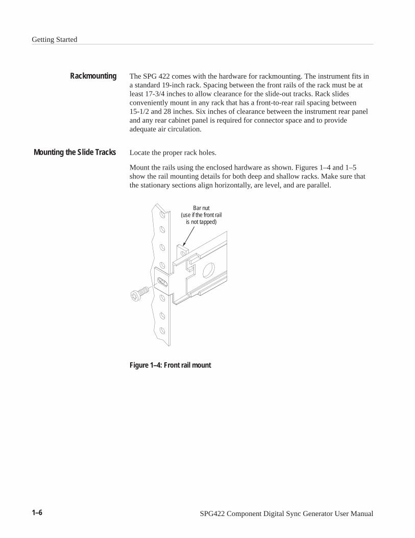
The SPG 422 comes with the hardware for rackmounting. The instrument fits ina standard 19-inch rack. Spacing between the front rails of the rack must be atleast 17-3/4 inches to allow clearance for the slide-out tracks. Rack slidesconveniently mount in any rack that has a front-to-rear rail spacing between15-1/2 and 28 inches. Six inches of clearance between the instrument rear paneland any rear cabinet panel is required for connector space and to provideadequate air circulation.
Locate the proper rack holes.
Mount the rails using the enclosed hardware as shown. Figures 1–4 and 1–5show the rail mounting details for both deep and shallow racks. Make sure thatthe stationary sections align horizontally, are level, and are parallel.
Bar nut(use if the front rail
is not tapped)
Figure 1–4: Front rail mount
Rackmounting
Mounting the Slide Tracks

Getting Started
SPG422 Component Digital Sync Generator User Manual 1–7
Rear rack rail
PNH screws
Bar nut
Flush with rear rack rail
Bar nut
Rear rack rail
PNH screws
Figure 1–5: Deep rackmount and shallow rackmount
Chassis section
Automatic latches
Stationary section
10-32 Phs screw
10-32 Phsscrews
Flat nut bars
Flat Nut Bar
Intermediatesection
Stop latch hole
Rear mounting
NOTE: Right hand and left hand stationary section isdesignated by the RH and the LH marked on the rails.Stop latch holes should be towards the bottom whenslides are in place. (The right hand rail is shown above.)
Figure 1–6: Assembly of rackmounting hardware

Getting Started
1–8 SPG422 Component Digital Sync Generator User Manual
Install the instrument in the rack, as shown in Figure 1–7.
TO INSTALL:1. Pull the slide-out track section to the fully extended position.
2. Insert the instrument chassis sections into the slide-outsections.
3. Press the stop latches and push the instrument toward therack until the latches snap into their holes.
4. Again press the stop latches and push the instrument fully intothe rack.
5. Tighten the front-panel retaining screw.
TO REMOVE:1. Loosen retaining screw and pull instrument outward until thestop latches snap into the holes.
2. Press stop latches and remove instrument.
Figure 1–7: Installing the instrument in the rack slides
After installation, the slide tracks may bind if improperly adjusted. To adjust thetracks, slide the instrument out about 10 inches, slightly loosen the screwsholding the tracks to the front rails, and allow the tracks to seek an unboundposition. Re-tighten the screws and check the tracks for smooth operation bysliding the instrument in and out of the rack several times.
Once the instrument is in place within the rack, tighten the knurled retainingscrew to fasten it securely into the rack.
The slide-out tracks do not require lubrication. The dark gray finish on the tracksis a permanent, lubricated coating.
First, loosen the front-panel knurled retaining screw. Grasp the front handles andpull the instrument out until all three slide sections latch. This holds theinstrument firmly in position.
To completely remove the instrument, first, be sure to disconnect all cabling.Then, press both release-latch buttons (visible in the stop-latch holes) andcarefully slide the instrument free from the tracks.
Installing the Instrument
Rack Adjustments
Rack Slide Maintenance
Removing the Instrument

Operating Basics


SPG422 Component Digital Sync Generator User Manual 2–1
Operating Basics
There is one input and several different kinds of outputs available from theSPG 422. This section explains what these signals are and how to use them.
Figure 2–1: Front panel of the SPG 422
GenlockThe genlock input accepts either NTSC, PAL, or CW inputs. The SPG 422expects the input to be an Analog Black reference signal either with or withoutburst. If burst is not present, then the SPG 422 can lock to the sync (instead ofburst lock). Configure the genlock as either a loopthrough or two terminatedinputs.
You can change the timing to compensate for any delays inherent in your system.
Please note that the SPG 422 cannot auto-detect the genlock input standard.Configure the genlock through the front panel or the RS-232 remote control.Setting up the Genlock Input signal has three parts: selecting video standard,selecting input configuration, and setting timing offset.
Genlock Video StandardThere are two different video standards to choose from (NTSC or PAL). Alsoyou can choose between burst lock and sync lock.
You can also select from a list of Continuous Wave frequencies: 3.58, 4.43, 1.0,5.0, or 10.0 MHz.
If the genlock is set to burst lock but the Input signal has no burst or it suddenlyloses burst, the menu display of the SPG 422 will say: “Reference Unknown”.All output signals will remain locked to the internal oscillator.

Operating Basics
2–2 SPG422 Component Digital Sync Generator User Manual
Genlock Input ConfigurationYou can connect the Genlock signal in three different ways. Figure 2–2illustrates the various options.
Referenceblack
To otherequipment
A B C
Master syncgenerator
Referenceblack
Master syncgenerator 1
Master syncgenerator 2
Referenceblack
Referenceblack
Master syncgenerator 1
Figure 2–2: Various ways to configure the Genlock input
Figure 2–2A shows the genlock as a loopthrough signal from Genlock A toGenlock B. This application is common when the SPG 422 is close to the mastersync generator and the master sync still has other equipment to feed.
Figure 2–2B shows two possible genlock inputs: Genlock 1 and Genlock 2.These are two different references. You can select which one you want from thefront panel. (Remember that the unselected genlock input is still terminated.) Anapplication for this setup is a dual standard suite. One genlock input would bethe 525/59.94 standard and the other 625/50 standard. Set some blacks for eachstandard, and the user can quickly shift between the standards with a menuchange.
Figure 2–2C shows a single genlock input. This is appropriate for the last signalin a reference chain.
Genlock TimingThe commands under this menu set the amount of advance or delay for all theoutput signals relative to the genlock input. The individual signals can then havetheir timing adjusted in their own menus.
You do not need to press ENTER for these commands. All changes will occur asyou make them.
Loopthrough
Two References
Single Reference

Operating Basics
SPG422 Component Digital Sync Generator User Manual 2–3
The submenus for genlock timing are: field timing, vertical offset, horizontaloffset, and fine horizontal offset.
Sets the amount of field offset using the left or right arrows. The maximumamount of offset is two fields of advance or delay.
The Genlock Vertical Offset sets the amount of vertical offset using the left andright arrows. The amount of offset can range from eight lines advance to eightlines delay.
Genlock Horizontal Offset sets the amount of horizontal offset using the right orleft arrow keys. It will move in units of clock cycles so the exact amount willvary depending upon the video standard selected. The total range of thehorizontal offset is ± line.
Genlock Fine Horizontal sets the fine horizontal timing. These increments are insub-clock-cycle units. The total range of the fine horizontal offset is ± line.
Black SignalsThere are at least two analog black outputs available from the rear panel. (If theSPG 422 is option 1, then there are six Analog Black outputs.) Configure eachseparately for standard, timing, and signal type. If the selected standard isdifferent from the genlock input, the SPG 422 locks to the internal oscillator thatis clock-locked to the genlock input. The timing offset range is ± 2 fields and±8 lines.
Bars SignalsThe Bars BNC connector outputs serial digital component color bars in either the525 or 625 standard. A timing shift of ± 1 field and ±8lines is available. It isnot necessary that the Bars output and the genlock input be the same standard. Ifthey are not the same standard, then the signal locks to the internal oscillator thatis clock-locked to the genlock. Select all variables from the Bars signals menu.
Serial BlackThe Serial Black signal is identical to the Serial Bars signal except the barssignal information has been stripped off and replaced with black. It takes itstiming offset information directly from the Serial Bars signal.
Genlock Field Timing
Genlock Vertical Offset
Genlock Horizontal Offset
Genlock Fine HorizontalOffset

Operating Basics
2–4 SPG422 Component Digital Sync Generator User Manual
Audio SignalsThere are three different formats of Serial Audio signals available from the rearpanel: AES/EBU from BNC connectors, AES/EBU from XLR connectors, andembedded audio in the Serial Digital Video signal. If any audio parameterschange, then all of the audio outputs are affected. Different audio tones andlevels are available for each channel. Up to four channels are available. Turnthem on or off and change the tone and levels independently.
Although the output frequency and amplitudes are the same, the AES andembedded audio are essentially generated by separate generators. Therefore,there is no consistent phase relationship between the two with respect to audiotones. The digital audio sample frames are synchronized with the video frame.(For more information see page 3–20 in the Reference section .)
Serial Signals (Option 2 only)If option 2 is not installed then these outputs are plugged. Both outputs haveidentical signals. There are a wide variety of signals from which to choose. Thetiming offset relative to the genlock is selectable. The standard is selectable andcan be independent of the genlock standard. If the standard is different from thegenlock, then it takes its timing from the internal oscillator that is clock-lockedto the Genlock signal. Therefore, the signal will be clock-locked but notframe-locked to the Genlock reference signal.

Operating Basics
SPG422 Component Digital Sync Generator User Manual 2–5
GENLOCK Reference
BLACK (1 or 2) Genlock
REFERENCE
DIGITAL TEST SIGNALS Genlock
BLACK (3–6) Genlock
–2 Fields–8 1/2 Lines
+2 Fields+8 1/2 Lines
DIGITAL BARS and BLACK Genlock
–2 Fields–8 1/2 Lines
+2 Fields+8 1/2 Lines
–1 Fields–8 1/2 Lines
+1 Fields+8 1/2 Lines
–2 Fields–8 1/2 Lines
+2 Fields+8 1/2 Lines
–1 Fields–8 1/2 Lines
+1 Fields+8 1/2 Lines
Timing Range Referenced to
Figure 2–3: Illustration of the SPG 422 timing

Operating Basics
2–6 SPG422 Component Digital Sync Generator User Manual

Reference


SPG422 Component Digital Sync Generator User Manual 3–1
Reference
This section describes how to control all the instrument functions using thefront-panel buttons and menus and the RS-232 REMOTE port.
Using the Front Panel Buttons and Menu DisplaysThe front-panel buttons and the Menu Display work together, providing you witha wide range of control, while keeping the front panel uncluttered.
The SPG 422 Menu Display is a two-line, 20-character-per-line LCD display.The SPG 422 displays messages corresponding to the position in the selectedmenus. The menus all have two lines of text, where the first line shows thecurrent position in the current menu, and the second line shows a user messageor the current selection (if there is not a submenu). If nothing is on the secondline, press ENTER to get to the corresponding submenu.
NOTE. In this section, the menu representations use Courier type to representdisplay letter spacing.
The menu discussion begins with the Main menu and then continues through themenus provided with each of the Select buttons.

Reference
3–2 SPG422 Component Digital Sync Generator User Manual
EXIT
EXIT
EXIT
0. SPG422 STATUS 525/NTSC SYNC LOCK
1. PRESET OPERATIONS
3. DIAGNOSTICS LOCK DIAGNOSTICS UNLOCKED
4. SELECT UTILITIES
5. SELECT DIAGNOSTIC
EXIT
ENTER
0. SOFTWARE VERSION V1.5.0 (c) TEK, 1999
1. INSTALLED OPTIONS STANDARD INSTRUMENT
2. INITIALIZE INSTR
3. INITIALIZE NVRAM
4. RS-232 LOOPBACK
5. EPROM TEST
6. RAM TESTS
0. DISPLAY BACKLIGHT ENABLED
1. DISPLAY CONTRAST <LOWER HIGHER>
2. EDIT SPG422 ID TEKTRONIX SPG 422
1. EDIT PRESET ID #1: SPG422 PRESET 1
2. SAVE INSTR TO #1: SPG422 PRESET 1
3. EDH INSERTION ENABLED
4. SET BAUD RATE 9600 BAUD
EXIT
EXIT
EXIT
EXIT
EXIT
EXIT
EXIT
EXIT
EXIT
ENTER
EXIT
EXIT
EXIT
EXIT
0. RECALL PRESET#1:SPG422 PRESET 1
ENTER
3. COPY PRESET #1: SPG422 PRESET 1
EXIT
EXIT
EXIT
2. CHARACTER ID
EXIT
EXIT
1. CHAR ID STATEID STATE ON
2. SELECT CHAR ID#2: SPG422 #2
3. EDIT CHAR ID #2:: SPG422 #2
ENTEREXIT
Figure 3–1: Illustration of the SPG 422 main menu

Reference
SPG422 Component Digital Sync Generator User Manual 3–3
Main MenuThe Main menu is available when you have not selected a Menu Select button.Pressing the up () or down () arrow button will scroll through the availableMain Menu submenus. Figure 3–1 illustrates the structure of the Main Menu.
SPG 422 STATUS. This menu has no submenu or selections. It is the top of theMain menu. Repeatedly pressing the EXIT button will always return to thismenu. The second line gives the genlock standard or status. If there is moreinformation to display, the left () or right () arrow button lights. Use thesebuttons to view the additional information. Following the front-panel lockouttime-out, the SPG 422 returns to the status menu.
The possible messages and actions if there are genlock errors are as follows:
ÁÁÁÁÁÁÁÁÁÁÁÁÁÁÁÁÁÁÁÁÁÁÁÁÁÁÁÁÁÁÁÁÁÁÁÁÁÁÁÁÁÁÁÁÁÁÁÁÁÁÁÁÁÁÁ
REF SOURCE UNKNOWN ÁÁÁÁÁÁÁÁÁÁÁÁÁÁÁÁÁÁÁÁÁÁÁÁÁÁÁÁÁÁÁÁÁÁÁÁÁÁÁÁÁÁÁÁÁÁÁÁÁÁÁÁÁÁÁÁÁÁÁÁÁÁÁÁÁ
The genlock source is absent or incom-patible. (Example: genlock signal is not con-nected). The instrument will automaticallyswitch to internal and the external REF LEDflashes.
ÁÁÁÁÁÁÁÁÁÁÁÁÁÁÁÁÁÁÁÁÁÁ
REF LOCK ERROR ÁÁÁÁÁÁÁÁÁÁÁÁÁÁÁÁÁÁÁÁÁÁÁÁÁÁ
The genlock source is noisy.ÁÁÁÁÁÁÁÁÁÁÁÁÁÁÁÁÁÁÁÁÁÁÁÁÁÁÁÁÁÁÁÁÁ
REF FREQUENCY ERRORÁÁÁÁÁÁÁÁÁÁÁÁÁÁÁÁÁÁÁÁÁÁÁÁÁÁÁÁÁÁÁÁÁÁÁÁÁÁÁ
The genlock frequency is outside its pull-inrange.
ÁÁÁÁÁÁÁÁÁÁÁÁÁÁÁÁÁÁÁÁÁÁÁÁÁÁÁÁÁÁÁÁÁ
REF LINE ERRORÁÁÁÁÁÁÁÁÁÁÁÁÁÁÁÁÁÁÁÁÁÁÁÁÁÁÁÁÁÁÁÁÁÁÁÁÁÁÁ
The line length is incorrect. (Example: NTSCand PAL are swapped)
ÁÁÁÁÁÁÁÁÁÁÁÁÁÁÁÁÁÁÁÁÁÁ
REF FIELD ERRORÁÁÁÁÁÁÁÁÁÁÁÁÁÁÁÁÁÁÁÁÁÁÁÁÁÁ
Incorrect number of lines/field.ÁÁÁÁÁÁÁÁÁÁÁÁÁÁÁÁÁÁÁÁÁÁREF FRAME ERROR
ÁÁÁÁÁÁÁÁÁÁÁÁÁÁÁÁÁÁÁÁÁÁÁÁÁÁColor frame error.ÁÁÁÁÁÁÁÁÁÁÁ
ÁÁÁÁÁÁÁÁÁÁÁÁÁÁÁÁÁÁÁÁÁÁÁÁÁÁÁÁÁÁÁÁÁ
INT REF TEMP ERRORÁÁÁÁÁÁÁÁÁÁÁÁÁÁÁÁÁÁÁÁÁÁÁÁÁÁÁÁÁÁÁÁÁÁÁÁÁÁÁÁÁÁÁÁÁÁÁÁÁÁÁÁ
Oscillator is outside its temperature range.(Example: needs more warm-up time or isoverheating)
ÁÁÁÁÁÁÁÁÁÁÁÁÁÁÁÁÁÁÁÁÁÁÁÁÁÁÁÁÁÁÁÁÁÁÁÁÁÁÁÁÁÁÁÁÁÁÁÁÁÁThe following messages may appear if there are no genlock errors:ÁÁÁÁÁÁÁÁÁÁÁÁÁÁÁÁÁÁÁÁÁÁINTERNAL
ÁÁÁÁÁÁÁÁÁÁÁÁÁÁÁÁÁÁÁÁÁÁÁÁÁÁÁÁÁÁÁÁÁÁÁÁÁÁÁÁÁ
ÁÁÁÁÁÁÁÁÁÁÁÁÁÁÁÁÁÁÁÁÁÁ
PAL BURST LOCKÁÁÁÁÁÁÁÁÁÁÁÁÁÁÁÁÁÁÁÁÁÁÁÁÁÁÁÁÁÁÁÁÁÁÁÁÁÁÁÁÁÁÁÁÁÁÁÁÁÁÁÁÁÁÁÁ
ÁÁÁÁÁÁÁÁÁÁÁNTSC BURST LOCK ÁÁÁÁÁÁÁÁÁÁÁÁÁÁÁ
ÁÁÁÁÁÁÁÁÁÁÁÁÁÁÁÁÁÁÁÁÁÁÁÁÁÁÁÁÁÁÁÁÁÁÁÁÁ
625/50 SYNC LOCK ÁÁÁÁÁÁÁÁÁÁÁÁÁÁÁÁÁÁÁÁÁÁÁÁÁÁÁÁÁÁÁÁÁÁÁÁÁÁÁÁÁ
ÁÁÁÁÁÁÁÁÁÁÁ525/59.94 SYNC LOCK
ÁÁÁÁÁÁÁÁÁÁÁÁÁÁÁÁÁÁÁÁÁÁÁÁÁÁÁÁÁÁÁÁÁÁÁÁÁÁÁÁÁ
ÁÁÁÁÁÁÁÁÁÁÁ4.43 MHZ CW LOCKÁÁÁÁÁÁÁÁÁÁÁÁÁÁÁÁÁÁÁÁÁÁÁÁÁÁÁÁÁÁÁÁÁÁÁÁÁÁÁÁÁ
ÁÁÁÁÁÁÁÁÁÁÁÁÁÁÁÁÁÁÁÁÁÁ
3.58 MHZ CW LOCKÁÁÁÁÁÁÁÁÁÁÁÁÁÁÁÁÁÁÁÁÁÁÁÁÁÁÁÁÁÁÁÁÁÁÁÁÁÁÁÁÁÁÁÁÁÁÁÁÁÁÁÁÁÁÁÁ
ÁÁÁÁÁÁÁÁÁÁÁ3.58 MHZ CW LOCK ÁÁÁÁÁÁÁÁÁÁÁÁÁÁÁ
ÁÁÁÁÁÁÁÁÁÁÁÁÁÁÁ

Reference
3–4 SPG422 Component Digital Sync Generator User Manual
ÁÁÁÁÁÁÁÁÁÁÁÁÁÁÁÁÁÁÁÁÁÁ
1.00 MHZ CW LOCK ÁÁÁÁÁÁÁÁÁÁÁÁÁÁÁÁÁÁÁÁÁÁÁÁÁÁÁÁÁÁÁÁÁÁÁÁÁÁÁÁÁ
ÁÁÁÁÁÁÁÁÁÁÁ5.00 MHZ CW LOCK ÁÁÁÁÁÁÁÁÁÁÁÁÁÁÁ
ÁÁÁÁÁÁÁÁÁÁÁÁÁÁÁÁÁÁÁÁÁÁÁÁÁÁÁÁÁÁÁÁÁÁÁÁÁ10.00 MHZ CW LOCK
ÁÁÁÁÁÁÁÁÁÁÁÁÁÁÁÁÁÁÁÁÁÁÁÁÁÁÁÁÁÁ
PRESET OPERATIONS. This menu is the access point to the Presets submenu. Forthe commands in the Presets submenu see page 3–5. The ENTER LED lights,indicating how to enter the Presets submenu.
CHARACTER ID. This menu is the access point to the Character ID submenu. TheCharacter ID add a text string to the Serial Bars output. For the commands in theCharacter ID menu, see page 3–6.
DIAGNOSTICS LOCK. This menu has no submenu. The second line is the currentdiagnostic lock status. If locked, you cannot execute any commands from theDiagnostic menu except the version and inventory queries. To change status,press the right () or left () arrow button and the status changes immediately.The various options are:
DIAGNOSTICS LOCKED
DIAGNOSTICS UNLOCKED
SELECT UTILITIES. This menu is the access point to the Utility submenu. For thecommands in the Utility submenu see page 3–7. The ENTER LED lights,indicating how to get to the Utility submenu.
SELECT DIAGNOSTICS. This menu is the access point to the Diagnostic submenu.For the commands in the Diagnostic submenu see page 3–9. The ENTER LEDlights, indicating how to enter the Diagnostic submenu.

Reference
SPG422 Component Digital Sync Generator User Manual 3–5
Presets is a submenu of the Main menu. To access these submenus, pressENTER when the Main menu has the Preset Operations option displayed. Thismenu contains assorted control commands not used on a regular basis. PressingEXIT will return you to the Main menu.
RECALL PRESETS. This menu has no submenu. The second line is the presetnumber and Preset identification string (see EDIT PRESET ID). Use the left ()or right () arrow button to select a different preset. After you make a change,the ENTER LED lights to remind you to press ENTER to implement theselection. After pressing ENTER, the selected preset is loaded. Any changes youmade affect the instrument. The various default options are:
ÁÁÁÁÁÁÁÁÁÁÁÁÁÁÁÁÁÁÁÁÁÁÁÁÁÁÁÁÁÁÁÁÁÁÁÁÁÁÁÁÁÁÁÁÁÁÁÁÁÁÁÁÁÁÁÁÁÁÁÁ
#1: SPG422 PRESET 1 ÁÁÁÁÁÁÁÁÁÁÁÁÁÁÁÁÁÁÁÁÁÁÁÁÁÁÁÁÁÁÁÁÁÁÁÁÁÁÁÁÁÁÁÁÁÁÁÁÁÁ
ÁÁÁÁÁÁÁÁÁÁÁÁÁÁÁÁÁÁÁÁ#2: SPG422 PRESET 2 ÁÁÁÁÁÁÁÁÁÁ
ÁÁÁÁÁÁÁÁÁÁÁÁÁÁÁÁÁÁÁÁÁÁÁÁÁÁÁÁÁÁÁÁÁÁÁÁÁÁÁÁÁÁÁÁÁÁÁÁÁÁ
#3: SPG422 PRESET 3 ÁÁÁÁÁÁÁÁÁÁÁÁÁÁÁÁÁÁÁÁÁÁÁÁÁÁÁÁÁÁÁÁÁÁÁÁÁÁÁÁ
ÁÁÁÁÁÁÁÁÁÁÁÁÁÁÁÁÁÁÁÁÁÁÁÁÁÁÁÁÁÁÁÁÁÁÁÁÁÁÁÁ
#4: SPG422 PRESET 4ÁÁÁÁÁÁÁÁÁÁÁÁÁÁÁÁÁÁÁÁÁÁÁÁÁÁÁÁÁÁThe response message for this menu (after pressing ENTER) is:
RECALLING PRESET #1
RECALLING PRESET #1LOADING BAR SIGNALS
RECALLING PRESET #1LOADING TEST SIGNALS
RECALLING PRESET #1LOADING AES AUDIO
RECALLING PRESET #1LOAD EMBEDDED AUDIO
EDIT PRESET ID. This menu has the EDIT PRESET ID submenu. The second lineis the current preset ID string. The LED on the ENTER button lights, indicatinghow to get to the ID submenu. Pressing ENTER begins editing the ID string.This submenu allows you to define and edit a 16-character ID string for thecurrent preset. Use the left () or right () arrow button to select which characterto modify. Use the up () or down () arrow button to choose the new
Presets Submenu

Reference
3–6 SPG422 Component Digital Sync Generator User Manual
character. Press ENTER to save the edited string. Press EXIT to leave thissubmenu without saving any changes.
SAVE INSTR TO. This menu is used to save the current instrument settings to oneof the four presets. When you first enter the menu, the second line shows the thepreset ID string, which is the default destination preset. Use the left () or right() arrow button to select the destination preset. The ENTER key accepts thechoice for destination preset. The response message for this menu is:
SAVING INSTR TO #1 SPG422 PRESET 1
COPY PRESET. This menu allows you to copy one instrument preset into another(but not onto itself). When you enter the menu, it shows the current preset ID. Tocopy a present, you first select the source preset and then the destination preset.
Use the left () or right () arrow button to select a source preset. Press theENTER key to accept the new source preset. The response message for thismenu is:
COPY PRESET #1 TO#2: SPG422 PRESET 2
Use the left () or right () arrow button to select the destination preset. PressENTER to accept the new destination preset. The display then responds with:
COPY PRESET COPYING PRESETS 1 ->2
To access these submenus, select Character ID and press ENTER. This menuallows you to select from four Character ID messages to output. You can edit thefour Character ID messages. Press EXIT to return to the Main menu.
This feature adds Character ID text to the Serial Bars output. Character IDoverlays a text string on the serial bar signal. You can select from four textstrings. You can also change the text for each text string. Character ID is activeonly when the Serial Bars signal is being output.
Enable Character ID. To enable Character ID, use the left () or right () arrowbutton to select ON or OFF for the CHARACTER ID.
Character ID Submenu

Reference
SPG422 Component Digital Sync Generator User Manual 3–7
Select a Character ID to Output. To select a different text string to output, use theleft () or right () arrow button to select from text strings #1 to #4 for output.
Press ENTER to make your selection active on the generator output. A messagewarns you that while the new text string is being loaded, the serial bar output isinvalid. Then you are prompted to accept or abort the loading of the new textstring.
Press the ENTER button to accept the selected Character ID text string foroutput. Press the EXIT button to not change the Character ID text string.
Upon pressing the ENTER button, the output display becomes unstable for a fewseconds, then the new text string appears on the serial bar output.
Edit Character ID Text. To change the Character ID text, use the left () or right() arrow button to select from #1 to #4 text strings. Press ENTER to edit theselected text string. Use the left () or right () arrow button to select a characterto change. Use the up () or down () arrow button to change the selectedcharacter.
The available characters include the full alphabet, numerals from 0 to 9, andmany standard ASCII symbols. The text strings may contain up to 10 characters.
Press ENTER to save the modified text string to NVRAM. This text string isnow available to output
Utility is a submenu of the Main menu. To access these submenus, press ENTERwhen the Main menu has the Utility submenu option displayed. This menucontains assorted control commands not used on a regular basis. Press EXIT toreturn to the Main menu.
DISPLAY BACKLIGHT. This menu has no submenu. This menu turns the backlightof the Menu Display on or off. Enabled turns the backlight on, disabled turns itoff. When the Menu Display is not in use, turn the backlight off for applicationswhere the backlight may be so bright that it is distracting.
DISPLAY CONTRAST. This menu has no submenu. This menu allows you to adjustthe contrast for the current viewing background light and angle. The second lineexplains how to adjust the Menu Display contrast. Use the left () arrow buttonto reduce the amount of contrast. Use the right () arrow button to increase theamount of contrast. The contrast value wraps around, so when the maximumvalue is reached the next value is the minimum value.
Utility Submenu

Reference
3–8 SPG422 Component Digital Sync Generator User Manual
EDIT SPG422 ID. This menu has the EDIT ID submenu. The second line is thecurrent instrument ID string. This ID is the name for the instrument. The MenuDisplay shows the ID at power-up and is the ID available when using the remote.
The LED on the ENTER button lights, indicating how to enter the ID submenu.This submenu allows you to define and edit a 16-character instrument ID string.Use the left () or right () arrow button to select the character to modify. Usethe up () or down () arrow button to choose the new character. Use theENTER key to save the edited string. Use the EXIT button to leave this submenuwithout saving any changes.
Pressing EXIT will stop the copying procedure without making any changes.(Basically you are copying the current preset information to the preset numberselected on the second line.)
EDH INSERTION. This menu has no submenu. The second line is the current ErrorDetection and Handling insertion status. This menu allows you to enable ordisable the generation and insertion of Error Detection and CRCs on all of theserial digital video signals. Use the right () or left () arrow button to turnCRCs on or off. Select from the following options:
ÁÁÁÁÁÁÁÁÁ
ÁÁÁÁÁÁÁÁÁÁÁÁÁÁÁÁÁÁÁÁÁÁÁÁÁÁÁ
ENABLED
ÁÁÁÁÁÁ
ÁÁÁÁÁÁÁÁÁÁÁÁÁÁÁÁÁÁ
DISABLED
SET BAUD RATE. This menu has no submenu. The second line is the current baudrate for the RS-232 remote control. This menu allows you to select between theavailable baud rates. Use the right () or left () arrows to select the baud rate.This command is only available from the front panel. Select from the followingoptions:
ÁÁÁÁÁÁ
ÁÁÁÁÁÁÁÁÁÁÁÁÁÁÁÁÁÁÁÁ
300 BAUDÁÁÁÁÁÁ
ÁÁÁÁÁÁÁÁÁÁÁÁÁÁÁÁÁÁÁÁ
600 BAUDÁÁÁÁÁÁ
ÁÁÁÁÁÁÁÁÁÁÁÁÁÁÁÁÁÁÁÁ 1200 BAUDÁÁÁ
ÁÁÁÁÁÁ
ÁÁÁÁÁÁÁÁÁÁÁÁÁÁÁÁÁÁÁÁÁÁÁÁÁÁÁÁÁÁ
2400 BAUD
ÁÁÁÁÁÁ
ÁÁÁÁÁÁÁÁÁÁÁÁÁÁÁÁÁÁÁÁ
4800 BAUD
ÁÁÁÁÁÁ
ÁÁÁÁÁÁÁÁÁÁÁÁÁÁÁÁÁÁÁÁ
9600 BAUD

Reference
SPG422 Component Digital Sync Generator User Manual 3–9
Access this submenu from the Diagnostic command line on the Main menu.Enter this submenu by pressing ENTER. Leave this submenu and return to theMain menu by pressing EXIT. If the diagnostics are locked out, only thesoftware version and installed option queries are available. (Unlock them usingthe Diagnostic Lock command on the Main menu.)
SOFTWARE VERSION. This menu has no submenu. The second line is a stringrepresenting the current software version number.
INSTALLED OPTIONS. This menu has no submenu. The second line is a stringrepresenting the options currently installed in the instrument. The list ofcurrently available responses is:
ÁÁÁÁÁÁÁÁ
ÁÁÁÁÁÁÁÁÁÁÁÁÁÁÁÁÁÁÁÁÁÁÁÁÁÁ
STANDARD INSTRUMENTÁÁÁÁÁÁÁÁ
ÁÁÁÁÁÁÁÁÁÁÁÁÁÁÁÁÁÁÁÁÁÁÁÁÁÁ
OPTION 1 INSTALLEDÁÁÁÁÁÁÁÁ
ÁÁÁÁÁÁÁÁÁÁÁÁÁÁÁÁÁÁÁÁÁÁÁÁÁÁOPTION 2 INSTALLEDÁÁÁÁ
ÁÁÁÁÁÁÁÁ
ÁÁÁÁÁÁÁÁÁÁÁÁÁÁÁÁÁÁÁÁÁÁÁÁÁÁÁÁÁÁÁÁÁÁÁÁÁÁÁ
OPTIONS 1 AND 2
INITIALIZE INSTR. This menu has no submenu. This menu allows you to initializethe SPG422 back to its original, factory, settings.
After pressing ENTER, this message is displayed:
INIT INST TO NTSC
Diagnostic Submenu

Reference
3–10 SPG422 Component Digital Sync Generator User Manual
The options are NTSC or PAL. Use the arrow buttons to make a selection. Aftermaking a selection and pressing ENTER, the Menu Displays the responsemessage.
INSTRUMENT INITIALIZ
INSTRUMENT INITIALIZLOADING BARS SIGNAL
INSTRUMENT INITIALIZLOADING TEST SIGNALS
INSTRUMENT INITIALIZLOADING AES AUDIO
INSTRUMENT INITIALIZLOAD EMBEDDED AUDIO
If you choose to not initialize the instrument, pressing EXIT will return you tothe Main menu without making any changes.
INITIALIZE NVRAM. This menu has no submenu. The LED on the ENTER buttonlights, indicating how to select the initialize NVRAM function.
CAUTION. When you initialize the NVRAM, it overwrites all data in the NVRAM.Use this command with discretion.
3. INITIALIZE NVRAMENTER TO CONTINUE
Press ENTER if you are sure you want to continue the operation. The responsemessages for this menu are:

Reference
SPG422 Component Digital Sync Generator User Manual 3–11
3. INITIALIZE NVRAMTESTING NVRAM
3. INITIALIZE NVRAMINITIALIZING NVRAM
TEKTRONIX SPG 422
TEKTRONIX SPG 422LOADING BARS SIGNALS
TEKTRONIX SPG 422LOADING TEST SIGNALS
TEKTRONIX SPG 422LOADING AES AUDIO
TEKTRONIX SPG 422LOADING AUDIO DATA
When the initialization is complete, the Menu Display returns to the top of theMain menu.
RS-232 LOOPBACK. This menu has no submenu. The LED on the ENTER buttonlights, indicating how to select the loopback diagnostic. This routine allows youto attach an RS-232 loopback plug to the Remote output connector and verifythat the RS-232 transmit and receive functions are working. The menu displaysthe following while the RS-232 test is operating:
4. RS-232 LOOPBACK
The available response messages are as follows:
LOOPBACK TEST PASSED
LOOPBACK TEST FAILED

Reference
3–12 SPG422 Component Digital Sync Generator User Manual
EPROM TEST. This menu has no submenu. The ENTER LED lights, indicatinghow to select the EPROM diagnostic. This routine allows you to run theEPROM checksum test to verify that the EPROM contents are intact. Afterpressing ENTER, the following message appears:
5. EPROM TESTTESTING CHECKSUMS
Once the test is completed, the display changes:
EPROM U10 TEST RESULTEPROM U11 TEST RESULT
EPROM U10 and EPROM U11 are located on the A2 Digital board.
The TEST RESULT messages will read one of two ways:
TEST PASSED
TEST FAILED
RAM TESTS. This menu has no submenu. The second line is the diagnosticmessage. This routine allows you to run the RAM Test to verify that theprocessor RAM and the RAMs in the audio and video generators are functional.Press ENTER to run the RAM Test. The following messages appear:
6. RAM TESTTESTING STATIC RAMS
TEKTRONIX SPG422
TEKTRONIX SPG422LOADING BARS SIGNALS
TEKTRONIX SPG422LOADING TEST SIGNALS

Reference
SPG422 Component Digital Sync Generator User Manual 3–13
TEKTRONIX SPG422LOADING AES AUDIO
TEKTRONIX SPG422LOADING AUDIO DATA
The available response messages are:
ALL RAM TESTS PASSED
AUDIO RAM FAILED
BARS RAM FAILED
EMBEDDED RAM FAILED
TEST RAM FAILED
Menus Available from the Select ButtonsThe following menus are available from the select buttons. To enter a SelectButton menu, press the desired select button. To leave a Select Button menu andreturn to the Main menu, press EXIT. Figure 3–2 illustrates this concept.
GENLOCK
BLACK (1 or 2)
SERIAL BARS AUDIO
BLACK (Opt. 1)
SERIAL SIGNALS(Opt. 2)
MAIN MENU press EXITpress EXIT
press BLACK(1 or 2)
press BLACK(3–6)
press GENLOCK
press EXIT
press SERIALSIGNALS
press EXIT
press EXIT
press SERIALAUDIO
press SERIAL BARS
press EXIT
Figure 3–2: How to access menus with the Select buttons

Reference
3–14 SPG422 Component Digital Sync Generator User Manual
Select the GENLOCK button to bring up the Genlock menu. Return to the Mainmenu by pressing EXIT. Use the up () or down () arrow button to scrollthrough the Genlock menu choices. Figure 3–3 illustrates the Genlock menustructure.
GENLOCK MODE. This menu has no submenu. The second line is the currentgenlock mode selection. Select the genlock mode using the left () or right ()arrow button. The change takes place when you leave this menu (scroll up ordown). The options are:
INTERNAL
PAL BURST LOCK
NTSC BURST LOCK
625/50 SYNC LOCK
525/59.94 SYNC LOCK
4.43 MHZ CW LOCK
3.58 MHZ CW LOCK
1.00 MHZ CW LOCK
5.00 MHZ CW LOCK
10.00 MHZ CW LOCK
Genlock Menu

Reference
SPG422 Component Digital Sync Generator User Manual 3–15
0. SPG 422 STATUS 525/59.94 SYNC LOCK
EXIT
EXIT
EXIT
EXIT
0. GENLOCK MODENTSC BURST LOCK
1. GENLOCK TIMING
2. CONFIGURE INPUTSLOOPTHROUGH 1-2
GENLOCK INTERNAL 4.43 MHz CW LockPAL BURST LOCK 3.58 MHz CW LockNTSC BURST LOCK 1.00 MHz CW Lock625/50 SYNC LOCK 5.00 MHz CW Lock525/59.94 SYNC LOCK 10.00 MHz CW Lock
ENTER
LOOPTHROUGH 1-2 TERMINATED INPUT 1TERMINATED INPUT 2
0. FIELD OFFSET 0 FIELDS OF OFFSET
1. VERTICAL OFFSET0 LINES OF OFFSET
2. HORIZONTAL OFFSET0.000 USEC OFFSET
3. FINE H OFFSET -_
delay up to 2 fields
advance up to 2 fields
delay up to 8 lines
advance up to 8 lines
delay up to 1/2 line
advance up to 1/2 line
delay
advance
EXIT
EXIT
EXIT
Figure 3–3: The Genlock menu structure
GENLOCK TIMING. This menu is the Timing submenu. The LED on the ENTERbutton lights, indicating how to get to the submenu. This menu allows you toadjust the timing of all outputs relative to the genlock source. The GenlockTiming submenu is essentially the same as any other Timing submenu. For thediscussion of the Timing submenu, see page 3–29.
CONFIGURE INPUTS. This menu has no submenu. This menu allows you toconfigure and select the genlock input connections. The second line is the currentinput configuration. Use the right () or left () arrow button to select from thefollowing options. In the terminate options, both genlock inputs are terminated,but only the selected one is used. The options are:
LOOP-THROUGH 1-2
TERMINATED INPUT 1
TERMINATED INPUT 2

Reference
3–16 SPG422 Component Digital Sync Generator User Manual
Enter this menu by pressing the SERIAL BARS select button. It allowsselection of the Serial Bars signal and the timing associated with it. PressingEXIT leaves this menu and returns to the Main menu. Figure 3–4 illustrates theSerial Bars menu structure.
SELECT BARS. This menu has no submenu. The second line is the current barssignal selection. This menu allows you to select the bars output test signal usingthe left () or right () arrow button. Changes do not occur until the ENTERbutton confirms the change and loads the new signal. Select from the signalsbelow:
SMPTE COLOR BARS (525 only)
75% BARS OVER RED (625 only)
100% BARS OVER RED (625 only)
75% COLOR BARS
100% COLOR BARS
SERIAL BLACK
0. SELECT SIGNALNEW SIGNAL SELECTED
0. SPG 422 STATUS 525/59.94 SYNC LOCK
EXIT
EXIT
EXIT
ENTER0. FIELD OFFSET 0 FIELDS OF OFFSET
1. VERTICAL OFFSET0 LINES OF OFFSET
2. HORIZONTAL OFFSET0.000 USEC OFFSET
delay up to 1 fields
advance up to 1 fields
delay up to 8 lines
advance up to 8 lines
delay up to 1/2 lines
advance up to 1/2 lines
EXIT
EXIT
EXIT
SERIAL BARS
ENTER
0. SELECT SIGNAL SMPTE COLOR BARS
1. SIGNAL TIMING
2. VIDEO STANDARD 525 LINE 59.94 HZ
525 Line 59.94 Hz625 Line 50 Hz
SMPTE Color Bars (525 only)75% Bars Over Red (625 only)100% Bars Over Red (625 only)75% Color Bars 100% Color BarsSerial Black
EXIT 3. BLACK SIGNAL AUDIO TONE
TONESILENCEAUDIO OFF
Figure 3–4: The Serial bars menu structure
Serial Bars Menu

Reference
SPG422 Component Digital Sync Generator User Manual 3–17
SIGNAL TIMING. This menu is the timing submenu. The LED on the ENTERbutton lights, indicating how to get to the submenu. This menu allows you tomove the timing of the serial bars and serial black outputs relative to thegenlock.
For more information on the Timing submenus, See Timing Menu on page 3–29.
VIDEO STANDARD. This menu has no submenu. The second line is the currentvideo standard. This menu allows you to choose between the 525/59.94 and625/50 video standards for the serial bars and serial black outputs. Press ENTERto initiate a change and load the new data.
2. VIDEO STANDARDLOADING BARS SIGNALS
You have two options:
525 LINE 59.94 HZ
625 LINE 50 HZ
BLACK SIGNAL AUDIO. This menu has no submenu. The second line is thecurrent selection of the embedded audio mode. The menu allows you to choosebetween AUDIO OFF, SILENCE, and TONE. This affects the serial black outputonly, and not the serial bars output. The change takes place when you leave thismenu (scroll up or down).
You have three BLACK SIGNAL AUDIO options:
AUDIO OFF: No audio in serial black signal
SILENCE: A 0 Hz tone is embedded in the serial black output.
TONE: The tone selected in the Serial Audio menu is embedded in the serialblack output.
If the second line reads EMB AUDIO DISABLED, then embedded audiohas been disabled in the Serial Audio menu. You must enable the embeddedaudio before you can make any selections in this menu.

Reference
3–18 SPG422 Component Digital Sync Generator User Manual
Access this menu by pressing the SERIAL AUDIO button. It allows you to setup the AES/EBU serial audio signal. First, select which channel(s) should havean audio signal. Then select the frequency and the amplitude of the tone. Alsoselect the number of bits (either 20 or 24) and information about embedded audioon the serial digital video signal. Pressing EXIT returns you to the Main menu.Figure 3–5 illustrates the structure of the Serial Audio menu.
SET FREQUENCY and LEVEL ON. This menu does have a submenu (the ENTERLED is lit indicating how to get to the submenu). The second line shows thecurrent channel selection. Use the right () or left () arrow button to scrollthrough the choices. This menu allows you to select the channel(s) to vary thefrequency and level (from its submenu). Select from the options below:
AUDIO CHANNEL 1 ONLY
AUDIO CHANNEL 2 ONLY
AUDIO CHANNEL 3 ONLY
AUDIO CHANNEL 4 ONLY
ALL AUDIO CHANNELS
Serial Audio Menu

Reference
SPG422 Component Digital Sync Generator User Manual 3–19
0. SPG 422 STATUS 525/59.94 SYNC LOCK
EXIT
EXIT
EXIT
EXIT
ENTER
EXIT
EXIT
EXIT
EXIT
SERIAL AUDIO
0. SET FREQ & LVL ON AUDIO CHANNEL 1 ONLY
1. AES AUDIO TIMING PAL REFERENCE
2. AES AUDIO WIDTH 20-BIT AUDIO DATA
3. EMBEDDED AUDIO ENABLED
4. EMBEDDED AUDIO ID EMB. AUDIO GROUP 1
6. AUDIO CLICK OFF
0. AUDIO FREQUENCY 800 HZ
1. AUDIO LEVEL –20 DBFS
Audio Channel 1 OnlyAudio Channel 2 OnlyAudio Channel 3 OnlyAudio Channel 4 OnlyAll Audio Channels
PAL Reference NTSC Ref. Phase 1NTSC Ref. Phase 2NTSC Ref. Phase 3NTSC Ref. Phase 4NTSC Ref. Phase 5
20-Bit Audio Data24-Bit Audio Data
EnabledDisabled
Emb. Audio Group 1Emb. Audio Group 2Emb. Audio Group 3Emb. Audio Group 4
No Emphasis BitsCD Emphasis BitsCCITT Emphasis Bits
800 Hz 1000 HzSilence
–20–18–16–14–12–10
EXIT 5. AUDIO EMPHASIS NO EMPHASIS BITS
OFFCHANNELS 1 & 3CHANNELS 2 & 4
Figure 3–5: The Serial Audio menu
After the channel has been selected, pressing ENTER confirms the choice andenters the Audio Level and Frequency submenu. See page 3–22 for an explana-tion of the Audio Level and Frequency submenu.
AES AUDIO TIMING. This menu has no submenu. The second line is the currentaudio timing reference. This menu allows you to move the timing of theAES/EBU outputs relative to the video genlock source. The options are:
PAL REFERENCE
NTSC REF. PHASE 1
NTSC REF. PHASE 2
Reference
3–20 SPG422 Component Digital Sync Generator User Manual
NTSC REF. PHASE 3
NTSC REF. PHASE 4
NTSC REF. PHASE 5
This timing is with respect to the Genlock timing; therefore, leave one of theBlack signals with zero timing change and use it as the reference for the audiosignals. For further details on Audio Timing, continue reading below; otherwise,skip to the SERIAL AUDIO WIDTH discussion on page 3–21.
The SPG 422 uses an internal video reference that may be genlocked to anexternal source with adjustable advance or delay. The AES/EBU digital audio isphase locked to that internal reference and follows its timing adjustment. Digitaland black burst output signals may be further adjusted with advance or delaywith respect to the internal reference. Therefore the black burst to digital audiophasing will be at the nominal (proposed standard) value only when the blackburst timing is set to zero (no advance or delay).
The proposed requirement for PAL audio timing is defined in EBU draftrecommendation R199 (12/1991) and requires that the start of the X (or Z)preamble be within + 1.04 µsec (5% of an audio sample) of the 50% point of theleading edge of sync on field 1 line 1. This only accounts for audio frame timing,and audio block timing is explicitly disregarded. Since there is an integer numberof audio samples (hence digital audio frames) in each video frame, there is onlyone possible nominal phase of digital audio with respect to video.
The requirement for NTSC audio timing is more complicated because of theNTSC frame rate. SMPTE proposed recommended practice S17.401 specifies atiming requirement that the start of the audio frame be within + 1 µsec of the50% point of the leading edge of the first equalizer on field 1 line 1. Audio blocktiming is not addressed. The NTSC audio timing only occurs once every fivevideo frames due to the non-integer number of audio samples per video frame.Since there is no five-frame reference information in the video, there are fivepossible phases of digital audio relative to video. The menu allows for selectionof one of the five phases.
Digital audio to video timing is straightforward with one audio signal and onevideo signal and an optional genlock input signal of the same line standard.Since there can be as many as six black burst outputs, the digital audio will becorrectly phased only with those outputs that have zero timing offset or whosetiming offset is within the phasing tolerance of the proposed standard. Again theblack burst signals must be of the same line standard as the genlock input signal,if any.
In the case where the black burst signal is of a different line standard than thegenlock input, there is no specified phase relation between the AES/EBU digitalaudio out and that black burst. With no genlock input, the digital audio will becorrectly phased with black burst signals of the line standard (PAL or NTSC)

Reference
SPG422 Component Digital Sync Generator User Manual 3–21
selected in the AES Audio Timing menu (recognizing the limitations statedabove).
AES AUDIO WIDTH. This menu has no submenu. This menu allows you to selectthe resolution of the serial digital audio signal data. The second line is thecurrent AES/EBU serial audio sample data width. Change between the twooptions using the right () or left () arrow button. Note that this selectionaffects all serial audio outputs. If a new option is selected, the ENTER LEDflashes to indicate then the ENTER button must be pressed to confirm the choiceand load the new data. When ENTER is pressed the following messages appear:
2. AES AUDIO WIDTHLOADING AES AUDIO
2. AES AUDIO WIDTHLOADING AUDIO DATA
The available options are:
20-BIT AUDIO DATA
24-BIT AUDIO DATA
EMBEDDED AUDIO. This menu has no submenu. The second line is the currentembedded audio insertion status. This menu allows you to enable or disable thegeneration and insertion of embedded audio on the serial digital video outputs.The frequency and levels of the embedded audio signal are the same as the serialaudio signal. Use the right () or left () arrow button to change between enabledand disabled. This command has no effect on the Serial Audio outputs. Selectfrom the following options:
ENABLED
DISABLED
EMBEDDED AUDIO ID. This menu has no submenu. The second line is the currentembedded audio group ID. The audio group ID defines which 4 of the 16possible channels are embedded in the serial digital video signal. Use the left ()or right () arrow button to make the selection. Note that this selection affects allserial video outputs. Select from the options below:
EMB. AUDIO GROUP 1 (Channels 1 – 4 are embedded in the video signal)
EMB. AUDIO GROUP 2 (Channels 5 – 8 are embedded in the video signal)
EMB. AUDIO GROUP 3 (Channels 9 – 12 are embedded in the video signal)

Reference
3–22 SPG422 Component Digital Sync Generator User Manual
EMB. AUDIO GROUP 4 (Channels 13 – 16 are embedded in the video signal)
AUDIO EMPHASIS. This menu has no submenu. The second line is the currentsetting of the audio emphasis bits. This menu allows you to select the state of theaudio emphasis bits. (There is never emphasis on the audio signal. This optiononly sets the status bits.) Use the right () or left () arrow button to select theemphasis. Note that this selection affects all serial audio and embedded audiooutputs. Select from the options below:
NO EMPHASIS BITS
CD EMPHASIS BITS
CCITT EMPHASIS BITS
The ENTER button lights if a new option is selected, to remind you to pressENTER to confirm the choice and load the new data. When ENTER is pressed,the following messages appear:
5. AUDIO EMPHASISLOADING AES AUDIO
5. AUDIO EMPHASISLOADING AUDIO DATA
AUDIO LEVEL AND FREQUENCY SUBMENU. You enter this submenu from theSET FREQ & LVL ON menu and it only affects the channels selected there.
AUDIO FREQUENCY. This menu has no submenu. The second line is the audiotone frequency for the currently selected channel(s). This menu allows you toselect the audio signal frequency using the left () or right () arrow button.Remember, any change only affects the channel(s) selected before entering thissubmenu. Pressing EXIT returns you to SET FREQ & LVL ON menu. Selectfrom the options below:
800 HZ
1000 HZ
SILENCE
If the option changes from the current selection the ENTER LED lights,reminding you to press the ENTER button to confirm the choice and load thenew data. When the ENTER button is pressed, the following messages appear:

Reference
SPG422 Component Digital Sync Generator User Manual 3–23
0. AUDIO FREQUENCYLOADING AES AUDIO
0. AUDIO FREQUENCYLOADING AUDIO DATA
AUDIO LEVEL. This menu has no submenu. The second line is the current audiotone amplitude for the currently selected audio channel(s). This menu allows youto select the audio signal amplitude (in dB below digital full-scale) using the left() or right () arrow button. Remember, any change only affects the channel(s)selected with the SET FREQ & LVL ON command. Select from the optionsbelow:
-20 DBFS
-18 DBFS
-16 DBFS
-14 DBFS
-12 DBFS
-10 DBFS
If silence is selected as the audio frequency, then the Audio Level menu onlystates Silence has 0 Ampl.
If the option changes from the current selection the ENTER LED lights,reminding you to press the ENTER button to confirm the choice and load thenew data. When the ENTER button is pressed, the following message appears:
1. AUDIO LEVELLOADING AES AUDIO
1. AUDIO LEVELLOADING AUDIO DATA

Reference
3–24 SPG422 Component Digital Sync Generator User Manual
AUDIO CLICK. This menu has no submenu. The second line is the current audioclick setting for the selected audio channel(s). Set Audio Click using the left ()or right () arrow button. Select from the options OFF, CHANNELS 1 & 3 orCHANNELS 2 & 4 to disable Audio Click or enable the specified clickchannels.
Audio Click makes it easy to identify the left and right audio channels and thestereo pairs of the four AES output channels. The Audio Click feature does notsupport embedded audio.
When you enable Audio Click, the audio outputs alternate between two sets ofsignals. Table 3–1 lists the audio signals output for each audio channel. TheSPG 422 alternates between driving the set 1 state for 2.75 seconds and set 2state for 0.25 seconds. In the set 2 state, the click channel is silent to helpidentify channels. In addition, to help distinguish each stereo pair, each pair has adifferent tone.
Table 3–1: Audio sets output for each channel
Audio channel Set 1 Set 2
AES1 non-click channel 1 kHz 1 kHz
AES1 click channel 1 kHz silent
AES2 non-click channel 800 Hz 800 Hz
AES2 click channel 800 Hz silent
Embedded Ch1 1 kHz 1 kHz
Embedded Ch2 1 kHz 1 kHz
Embedded Ch3 800 Hz 800 Hz
Embedded Ch4 800 Hz 800 Hz
When you enable Audio Click, the settings of all audio channels are savedinternally. These settings are restored when you disable Audio Click. When theAudio Click is enabled, other audio settings, such as level and frequency, cannotbe changed. The audio tones use the audio level last set for each channel. Tochange other audio settings, first turn Audio Click off.
Menus similar to these access the various Analog Black signal menus—theBlack button selects which Black output. Blacks 1 and 2 are available on allinstruments. Blacks 3 through 6 are only available on instruments with option 1installed. These menus cover the type of black signal and timing available fromthe corresponding black BNC connector on the rear panel. Pressing EXIT returnsyou to the Main menu. Figure 3–6 illustrates Black 1 and 2 menu structure,while Figure 3–7 illustrates Blacks 3 through 6 menu structure.
Black Menus
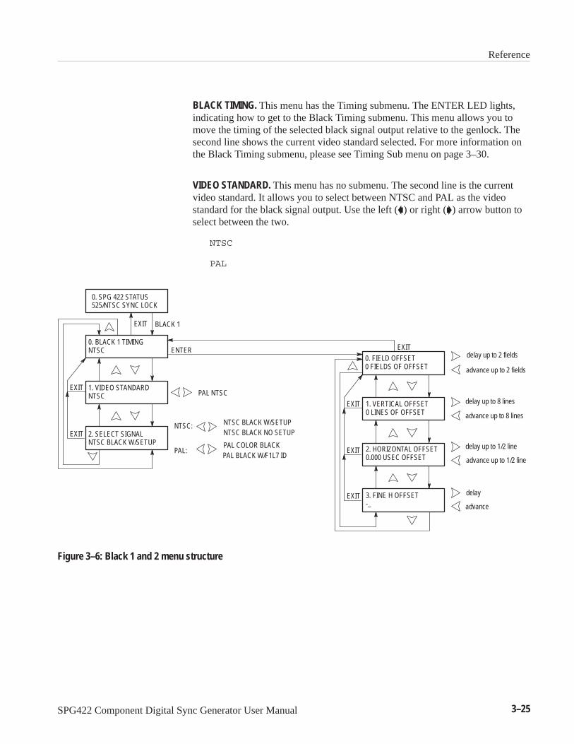
Reference
SPG422 Component Digital Sync Generator User Manual 3–25
BLACK TIMING. This menu has the Timing submenu. The ENTER LED lights,indicating how to get to the Black Timing submenu. This menu allows you tomove the timing of the selected black signal output relative to the genlock. Thesecond line shows the current video standard selected. For more information onthe Black Timing submenu, please see Timing Sub menu on page 3–30.
VIDEO STANDARD. This menu has no submenu. The second line is the currentvideo standard. It allows you to select between NTSC and PAL as the videostandard for the black signal output. Use the left () or right () arrow button toselect between the two.
NTSC
PAL
0. SPG 422 STATUS 525/NTSC SYNC LOCK
EXIT
EXIT
EXIT
EXIT
ENTER0. FIELD OFFSET 0 FIELDS OF OFFSET
1. VERTICAL OFFSET0 LINES OF OFFSET
2. HORIZONTAL OFFSET0.000 USEC OFFSET
3. FINE H OFFSET -_
delay up to 2 fields
advance up to 2 fields
delay up to 8 lines
advance up to 8 lines
delay up to 1/2 line
advance up to 1/2 line
delay
advance
EXIT
EXIT
EXIT
PAL NTSC
NTSC:
PAL:
0. BLACK 1 TIMINGNTSC
1. VIDEO STANDARD NTSC
2. SELECT SIGNAL NTSC BLACK W/SETUP
NTSC BLACK W/SETUPNTSC BLACK NO SETUP
PAL COLOR BLACKPAL BLACK W/F1L7 ID
BLACK 1
Figure 3–6: Black 1 and 2 menu structure

Reference
3–26 SPG422 Component Digital Sync Generator User Manual
0. SPG 422 STATUS 525/NTSC SYNC LOCK
EXIT
EXIT
EXIT
ENTER0. FIELD OFFSET 0 FIELDS OF OFFSET
1. VERTICAL OFFSET0 LINES OF OFFSET
2. HORIZONTAL OFFSET0.000 USEC OFFSET
delay up to 2 fields
advance up to 2 fields
delay up to 8 lines
advance up to 8 lines
delay up to 1/2 line
advance up to 1/2 line
EXIT
EXIT
EXIT
PAL NTSC
NTSC:
PAL:
0. BLACK 3 TIMINGNTSC
1. VIDEO STANDARD NTSC
2. SELECT SIGNAL NTSC BLACK W/SETUP
NTSC BLACK W/SETUPNTSC BLACK NO SETUP
PAL COLOR BLACKPAL BLACK W/F1L7 ID
BLACK 3
Figure 3–7: Black 3 through 6 menu structure
SELECT SIGNAL. This menu has no submenu. The second line is the currentblack signal. This menu allows you to select the black signal (valid for the videostandard) using the left () or right () arrow button. Select from the followingoptions:
NTSC BLACK W/ SETUP
NTSC BLACK NO SETUP
PAL COLOR BLACK
PAL BLACK W/ F1L7 ID

Reference
SPG422 Component Digital Sync Generator User Manual 3–27
These signals are only available if option 2 is installed. This menu selects theserial digital video signal available at the Serial signal BNC connectors on therear panel. It also selects the timing relative to the genlock and the standard (525or 625). Pressing EXIT returns to the Main menu. Figure 3–8 illustrates themenu structure for the Serial signals.
0. SPG 422 STATUS 525/59.94 SYNC LOCK
EXIT
EXIT
EXIT
ENTER0. FIELD OFFSET 0 FIELDS OF OFFSET
1. VERTICAL OFFSET0 LINES OF OFFSET
2. HORIZONTAL OFFSET0.000 USEC OFFSET
delay up to 1 fields
advance up to 1 fields
delay up to 8 lines
advance up to 8 lines
delay up to 1/2 lines
advance up to 1/2 lines
EXIT
EXIT
EXIT
SERIAL SIGNALS
ENTER
0. SELECT SIGNAL 75% COLOR BARS
1. SIGNAL TIMING
2. VIDEO STANDARD 525 LINE 59.94 HZ
525 Line 59.94 Hz625 Line 50 Hz
75% Color Bars 100% Color BarsFull Field PlugeConvergenceBowtie MatrixActive Picture Mark
MultiBurstPulse and BarLimit RampSDI Check FieldSerial BlackWhite Bar40% Gray
Figure 3–8: The Serial Signals menu structure
SELECT SIGNAL. This menu has no submenu. The second line is the currentserial signal selection. This menu allows selection of the serial signal outputusing the left () or right () arrow button. Press the ENTER button to acceptany changes and load the new signal. After pressing ENTER, the follow messageappears:
0. SELECT SIGNALNEW SIGNAL SELECTED
The available signals are:
75% COLOR BARS
100% COLOR BARS
FULL FIELD PLUGE
CONVERGENCE
Serial Signals Menu

Reference
3–28 SPG422 Component Digital Sync Generator User Manual
BOWTIE MATRIX
ACTIVE PICTURE MARKER
MULTIBURST
PULSE AND BAR
LIMIT RAMP
SDI CHECK FIELD
SERIAL BLACK
WHITE BAR
40% GRAY
SIGNAL TIMING. This menu has the Timing submenu. The LED on the ENTERbutton lights, indicating how to get to the Serial signal submenu. This menuallows you to move the timing of the serial signal outputs relative to the genlock.
For more information on the Black Timing submenu, please see Timing submenudiscussion, below.
VIDEO STANDARD. This menu has no submenu. The second line shows thecurrent video standard. This menu allows you to select between the 525/59.94and 625/50 video standards for the serial signal outputs. Use the right () or left() arrow button to select between the two standards. Press ENTER to confirmthe change and load the new signal. When ENTER is pressed the followingmessage appears:
2. VIDEO STANDARDLOADING TEST SIGNALS
Select from the following:
525 LINE / 59.94 HZ
625 LINE / 50 HZ

Reference
SPG422 Component Digital Sync Generator User Manual 3–29
The Timing submenu is very similar in all of its occurrences. It allows the timingof the output signal to shift relative to the genlock signal. The ENTER buttonnever needs to be pressed to accept a choice in this submenu––all changes takeplace immediately. Press ENTER to enter this submenu. EXIT returns to thestarting menu.
FIELD OFFSET. This menu has no submenu. The second line is the current fieldtiming offset. This command allows you to move the selected output timing (orgenlock timing) in field increments, relative to the genlock, using the left () orright () arrow button. The options are:
2 FIELDS OF ADVANCE
1 FIELD OF ADVANCE
0 FIELDS OF OFFSET
1 FIELD OF DELAY
2 FIELDS OF DELAY
VERTICAL OFFSET. This menu has no submenu. The second line is the currentvertical timing offset. This allows you to move the timing in video lineincrements, relative to the genlock. The left () or right () arrow button scrollsthrough the choices. The choices are:
8 LINES OF ADVANCE
7 LINES OF ADVANCE
6 LINES OF ADVANCE
5 LINES OF ADVANCE
4 LINES OF ADVANCE
3 LINES OF ADVANCE
2 LINES OF ADVANCE
1 LINE OF ADVANCE
0 LINES OF OFFSET
1 LINE OF DELAY
2 LINES OF DELAY
3 LINES OF DELAY
4 LINES OF DELAY
Timing Submenu

Reference
3–30 SPG422 Component Digital Sync Generator User Manual
5 LINES OF DELAY
6 LINES OF DELAY
7 LINES OF DELAY
8 LINES OF DELAY
HORIZONTAL OFFSET. This menu has no submenu. The second line is the currenthorizontal timing offset. This command allows you to move the selected timingin clock-cycle increments, using the left () or right () arrow button.
FINE HORIZONTAL OFFSET. This menu has no submenu and is only availablefrom some menus. The second line changes from “—” to “|”, to indicated thatthe horizontal offset is changing. This routine allows you to move the selectedtiming in sub-clock-cycle increments, using the left () or right () arrow button.The total offset range is one clock-cycle.

Reference
SPG422 Component Digital Sync Generator User Manual 3–31
Using the RS-232 Remote
The remote connector on the rear panel can be either a simple ground-closureremote or an RS-232 port. This section discusses the RS-232 configuration. (Setinternal jumpers to select the configuration.)
Many of the commands that the SPG 422 front panel and menu generate areaccessible using a dumb terminal and the Remote port. The following sectionexplains how to install a terminal and how to use the commands.
An RS-232 cable is needed to connect the Terminal port to the SPG 422 Remoteport. Order a cable that will support both the terminal and the Remote port.
Use the following steps to set up for RS-232 remote use:
1. Use the front-panel menu to set the SPG 422 baud rate to 9600 (or whateverthe terminal requires).
2. Disconnect the power from both the terminal and the SPG 422.
3. Attach the cable to the Terminal RS-232 port and to the SPG 422 Remoteinput, as shown in Figure 3–9.
4. Set the terminal baud rate to 9600 (or whatever is appropriate), eight bits,one stop bit, no parity, and ECHO REMOTE. (Use the instructions providedwith the terminal to make these changes.)
5. Remove the top cover from the SPG 422.
6. If necessary, move the remote port cable to the connector labeled “RS-232”.
Terminal
SPG 422
Figure 3–9: How to connect the terminal
7. Replace the top cover of the SPG 422.
Using the Parser
Installation

Reference
3–32 SPG422 Component Digital Sync Generator User Manual
8. Return power to both the terminal and the SPG 422.
9. When the terminal is ready, a prompt will appear on the terminal:
SPG422>
The Parser is now ready to accept commands.
The following pages give the Parser Tree, which is the hierarchy of the commandstrings.
The RS-232 Remote Control menu is as follows:
Square brackets ([]) enclose optional parameters.
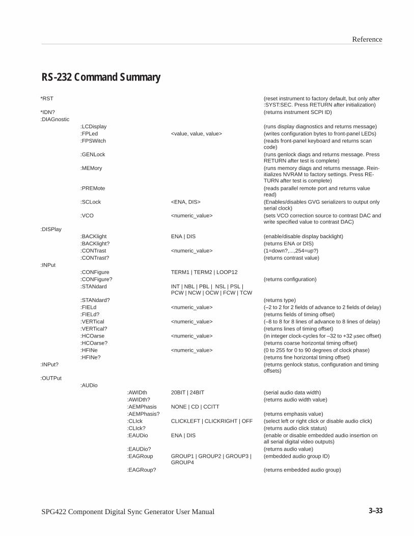
Reference
SPG422 Component Digital Sync Generator User Manual 3–33
RS-232 Command Summary
ÁÁÁÁÁÁÁÁÁÁ
*RST ÁÁÁÁÁÁÁÁÁÁ
ÁÁÁÁÁÁÁÁÁÁÁÁ
ÁÁÁÁÁÁÁÁÁÁÁÁÁÁÁÁÁÁÁÁ
ÁÁÁÁÁÁÁÁÁÁÁÁÁÁÁÁÁÁÁÁÁÁÁÁÁÁ
(reset instrument to factory default, but only after:SYST:SEC. Press RETURN after initialization)
ÁÁÁÁÁÁÁÁÁÁ
*IDN? ÁÁÁÁÁÁÁÁÁÁ
ÁÁÁÁÁÁÁÁÁÁÁÁ
ÁÁÁÁÁÁÁÁÁÁÁÁÁÁÁÁÁÁÁÁ
ÁÁÁÁÁÁÁÁÁÁÁÁÁÁÁÁÁÁÁÁÁÁÁÁÁÁ
(returns instrument SCPI ID)
ÁÁÁÁÁ:DIAGnostic ÁÁÁÁÁÁÁÁÁÁÁÁÁÁÁÁÁÁÁÁÁÁÁÁÁÁÁÁÁÁÁÁÁÁÁÁÁÁÁÁÁÁÁÁ
ÁÁÁÁÁÁÁÁÁÁ
:LCDisplayÁÁÁÁÁÁÁÁÁÁÁÁ
ÁÁÁÁÁÁÁÁÁÁÁÁÁÁÁÁÁÁÁÁ
ÁÁÁÁÁÁÁÁÁÁÁÁÁÁÁÁÁÁÁÁÁÁÁÁÁÁ
(runs display diagnostics and returns message)ÁÁÁÁÁÁÁÁÁÁ
ÁÁÁÁÁÁÁÁÁÁ
:FPLed ÁÁÁÁÁÁÁÁÁÁÁÁ
ÁÁÁÁÁÁÁÁÁÁÁÁÁÁÁÁÁÁÁÁ
<value, value, value> ÁÁÁÁÁÁÁÁÁÁÁÁÁÁÁÁÁÁÁÁÁÁÁÁÁÁ
(writes configuration bytes to front-panel LEDs)
ÁÁÁÁÁÁÁÁÁÁ
ÁÁÁÁÁÁÁÁÁÁ
:FPSWitch ÁÁÁÁÁÁÁÁÁÁÁÁ
ÁÁÁÁÁÁÁÁÁÁÁÁÁÁÁÁÁÁÁÁ
ÁÁÁÁÁÁÁÁÁÁÁÁÁÁÁÁÁÁÁÁÁÁÁÁÁÁ
(reads front-panel keyboard and returns scancode)
ÁÁÁÁÁÁÁÁÁÁ
ÁÁÁÁÁÁÁÁÁÁ
:GENLock ÁÁÁÁÁÁÁÁÁÁÁÁ
ÁÁÁÁÁÁÁÁÁÁÁÁÁÁÁÁÁÁÁÁ
ÁÁÁÁÁÁÁÁÁÁÁÁÁÁÁÁÁÁÁÁÁÁÁÁÁÁ
(runs genlock diags and returns message. PressRETURN after test is complete)ÁÁÁÁÁ
ÁÁÁÁÁÁÁÁÁÁ
ÁÁÁÁÁÁÁÁÁÁÁÁÁÁÁ
:MEMoryÁÁÁÁÁÁÁÁÁÁÁÁÁÁÁÁÁÁ
ÁÁÁÁÁÁÁÁÁÁÁÁÁÁÁÁÁÁÁÁÁÁÁÁÁÁÁÁÁÁ
ÁÁÁÁÁÁÁÁÁÁÁÁÁÁÁÁÁÁÁÁÁÁÁÁÁÁÁÁÁÁÁÁÁÁÁÁÁÁÁ
(runs memory diags and returns message. Rein-itializes NVRAM to factory settings. Press RE-TURN after test is complete)ÁÁÁÁÁ
ÁÁÁÁÁÁÁÁÁÁ
ÁÁÁÁÁÁÁÁÁÁÁÁÁÁÁ
:PREMoteÁÁÁÁÁÁÁÁÁÁÁÁÁÁÁÁÁÁ
ÁÁÁÁÁÁÁÁÁÁÁÁÁÁÁÁÁÁÁÁÁÁÁÁÁÁÁÁÁÁ
ÁÁÁÁÁÁÁÁÁÁÁÁÁÁÁÁÁÁÁÁÁÁÁÁÁÁÁÁÁÁÁÁÁÁÁÁÁÁÁ
(reads parallel remote port and returns valueread)
ÁÁÁÁÁÁÁÁÁÁ
ÁÁÁÁÁÁÁÁÁÁ
:SCLock ÁÁÁÁÁÁÁÁÁÁÁÁ
ÁÁÁÁÁÁÁÁÁÁÁÁÁÁÁÁÁÁÁÁ
<ENA, DIS> ÁÁÁÁÁÁÁÁÁÁÁÁÁÁÁÁÁÁÁÁÁÁÁÁÁÁ
(Enables/disables GVG serializers to output onlyserial clock)
ÁÁÁÁÁÁÁÁÁÁ
ÁÁÁÁÁÁÁÁÁÁ
:VCO ÁÁÁÁÁÁÁÁÁÁÁÁ
ÁÁÁÁÁÁÁÁÁÁÁÁÁÁÁÁÁÁÁÁ
<numeric_value> ÁÁÁÁÁÁÁÁÁÁÁÁÁÁÁÁÁÁÁÁÁÁÁÁÁÁ
(sets VCO correction source to contrast DAC andwrite specified value to contrast DAC)ÁÁÁÁÁ
ÁÁÁÁÁ:DISPlay ÁÁÁÁÁ
ÁÁÁÁÁÁÁÁÁÁÁÁÁÁÁÁÁ
ÁÁÁÁÁÁÁÁÁÁÁÁÁÁÁÁÁÁÁÁ
ÁÁÁÁÁÁÁÁÁÁÁÁÁÁÁÁÁÁÁÁÁÁÁÁÁÁÁÁÁÁÁ
ÁÁÁÁÁÁÁÁÁÁÁÁÁÁÁ
:BACKlight ÁÁÁÁÁÁÁÁÁÁÁÁ
ÁÁÁÁÁÁÁÁÁÁÁÁÁÁÁÁÁÁÁÁ
ENA | DIS ÁÁÁÁÁÁÁÁÁÁÁÁÁÁÁÁÁÁÁÁÁÁÁÁÁÁ
(enable/disable display backlight)
ÁÁÁÁÁÁÁÁÁÁ:BACKlight? ÁÁÁÁÁÁÁÁÁÁÁÁÁÁÁÁÁÁÁÁÁÁÁÁÁÁÁÁÁ(returns ENA or DIS)ÁÁÁÁÁÁÁÁÁÁ
ÁÁÁÁÁÁÁÁÁÁ
:CONTrastÁÁÁÁÁÁÁÁÁÁÁÁ
ÁÁÁÁÁÁÁÁÁÁÁÁÁÁÁÁÁÁÁÁ
<numeric_value>ÁÁÁÁÁÁÁÁÁÁÁÁÁÁÁÁÁÁÁÁÁÁÁÁÁÁ
(1=down?,...,254=up?)ÁÁÁÁÁÁÁÁÁÁ
ÁÁÁÁÁÁÁÁÁÁ
:CONTrast? ÁÁÁÁÁÁÁÁÁÁÁÁ
ÁÁÁÁÁÁÁÁÁÁÁÁÁÁÁÁÁÁÁÁ
ÁÁÁÁÁÁÁÁÁÁÁÁÁÁÁÁÁÁÁÁÁÁÁÁÁÁ
(returns contrast value)
ÁÁÁÁÁ:INPut ÁÁÁÁÁÁÁÁÁÁÁÁÁÁÁÁÁÁÁÁÁÁÁÁÁÁÁÁÁÁÁÁÁÁÁÁÁÁÁÁÁÁÁÁ
ÁÁÁÁÁÁÁÁÁÁ
:CONFigureÁÁÁÁÁÁÁÁÁÁÁÁ
ÁÁÁÁÁÁÁÁÁÁÁÁÁÁÁÁÁÁÁÁ
TERM1 | TERM2 | LOOP12ÁÁÁÁÁÁÁÁÁÁÁÁÁÁÁÁÁÁÁÁÁÁÁÁÁÁÁÁÁÁÁ
ÁÁÁÁÁÁÁÁÁÁÁÁÁÁÁ
:CONFigure?ÁÁÁÁÁÁÁÁÁÁÁÁ
ÁÁÁÁÁÁÁÁÁÁÁÁÁÁÁÁÁÁÁÁ
ÁÁÁÁÁÁÁÁÁÁÁÁÁÁÁÁÁÁÁÁÁÁÁÁÁÁ
(returns configuration)
ÁÁÁÁÁÁÁÁÁÁ
ÁÁÁÁÁÁÁÁÁÁ
:STANdard ÁÁÁÁÁÁÁÁÁÁÁÁ
ÁÁÁÁÁÁÁÁÁÁÁÁÁÁÁÁÁÁÁÁ
INT | NBL | PBL | NSL | PSL |PCW | NCW | OCW | FCW | TCW
ÁÁÁÁÁÁÁÁÁÁÁÁÁÁÁÁÁÁÁÁÁÁÁÁÁÁÁÁÁÁÁ
ÁÁÁÁÁÁÁÁÁÁÁÁÁÁÁ
:STANdard? ÁÁÁÁÁÁÁÁÁÁÁÁ
ÁÁÁÁÁÁÁÁÁÁÁÁÁÁÁÁÁÁÁÁ
ÁÁÁÁÁÁÁÁÁÁÁÁÁÁÁÁÁÁÁÁÁÁÁÁÁÁ
(returns type)
ÁÁÁÁÁÁÁÁÁÁ:FIELd ÁÁÁÁÁÁÁÁÁÁÁÁÁÁÁÁ<numeric_value> ÁÁÁÁÁÁÁÁÁÁÁÁÁ(–2 to 2 for 2 fields of advance to 2 fields of delay)ÁÁÁÁÁÁÁÁÁÁ
ÁÁÁÁÁÁÁÁÁÁ
:FIELd?ÁÁÁÁÁÁÁÁÁÁÁÁ
ÁÁÁÁÁÁÁÁÁÁÁÁÁÁÁÁÁÁÁÁ
ÁÁÁÁÁÁÁÁÁÁÁÁÁÁÁÁÁÁÁÁÁÁÁÁÁÁ
(returns fields of timing offset)ÁÁÁÁÁÁÁÁÁÁ
ÁÁÁÁÁÁÁÁÁÁ
:VERTical ÁÁÁÁÁÁÁÁÁÁÁÁ
ÁÁÁÁÁÁÁÁÁÁÁÁÁÁÁÁÁÁÁÁ
<numeric_value> ÁÁÁÁÁÁÁÁÁÁÁÁÁÁÁÁÁÁÁÁÁÁÁÁÁÁ
(–8 to 8 for 8 lines of advance to 8 lines of delay)
ÁÁÁÁÁÁÁÁÁÁ
ÁÁÁÁÁÁÁÁÁÁ
:VERTical? ÁÁÁÁÁÁÁÁÁÁÁÁ
ÁÁÁÁÁÁÁÁÁÁÁÁÁÁÁÁÁÁÁÁ
ÁÁÁÁÁÁÁÁÁÁÁÁÁÁÁÁÁÁÁÁÁÁÁÁÁÁ
(returns lines of timing offset)
ÁÁÁÁÁÁÁÁÁÁ:HCOarse ÁÁÁÁÁÁÁÁÁÁÁÁÁÁÁÁ<numeric_value> ÁÁÁÁÁÁÁÁÁÁÁÁÁ(in integer clock-cycles for –32 to +32 sec offset)ÁÁÁÁÁÁÁÁÁÁ
ÁÁÁÁÁÁÁÁÁÁ
:HCOarse? ÁÁÁÁÁÁÁÁÁÁÁÁ
ÁÁÁÁÁÁÁÁÁÁÁÁÁÁÁÁÁÁÁÁ
ÁÁÁÁÁÁÁÁÁÁÁÁÁÁÁÁÁÁÁÁÁÁÁÁÁÁ
(returns coarse horizontal timing offset)
ÁÁÁÁÁÁÁÁÁÁ
ÁÁÁÁÁÁÁÁÁÁ
:HFINe ÁÁÁÁÁÁÁÁÁÁÁÁ
ÁÁÁÁÁÁÁÁÁÁÁÁÁÁÁÁÁÁÁÁ
<numeric_value> ÁÁÁÁÁÁÁÁÁÁÁÁÁÁÁÁÁÁÁÁÁÁÁÁÁÁ
(0 to 255 for 0 to 90 degrees of clock phase)
ÁÁÁÁÁÁÁÁÁÁ:HFINe? ÁÁÁÁÁÁÁÁÁÁÁÁÁÁÁÁÁÁÁÁÁÁÁÁÁÁÁÁÁ(returns fine horizontal timing offset)ÁÁÁÁÁÁÁÁÁÁÁÁÁÁÁ
:INPut? ÁÁÁÁÁÁÁÁÁÁÁÁÁÁÁ
ÁÁÁÁÁÁÁÁÁÁÁÁÁÁÁÁÁÁ
ÁÁÁÁÁÁÁÁÁÁÁÁÁÁÁÁÁÁÁÁÁÁÁÁÁÁÁÁÁÁ
ÁÁÁÁÁÁÁÁÁÁÁÁÁÁÁÁÁÁÁÁÁÁÁÁÁÁÁÁÁÁÁÁÁÁÁÁÁÁÁ
(returns genlock status, configuration and timingoffsets)
ÁÁÁÁÁ:OUTPut ÁÁÁÁÁÁÁÁÁÁÁÁÁÁÁÁÁÁÁÁÁÁÁÁÁÁÁÁÁÁÁÁÁÁÁÁÁÁÁÁÁÁÁÁ
ÁÁÁÁÁÁÁÁÁÁ
:AUDio ÁÁÁÁÁÁÁÁÁÁÁÁ
ÁÁÁÁÁÁÁÁÁÁÁÁÁÁÁÁÁÁÁÁ
ÁÁÁÁÁÁÁÁÁÁÁÁÁÁÁÁÁÁÁÁÁÁÁÁÁÁÁÁÁÁÁ
ÁÁÁÁÁÁÁÁÁÁÁÁÁÁÁ
ÁÁÁÁÁÁÁÁÁÁÁÁ
:AWIDth ÁÁÁÁÁÁÁÁÁÁÁÁÁÁÁÁÁÁÁÁ
20BIT | 24BIT ÁÁÁÁÁÁÁÁÁÁÁÁÁÁÁÁÁÁÁÁÁÁÁÁÁÁ
(serial audio data width)
ÁÁÁÁÁÁÁÁÁÁÁÁÁÁÁÁ:AWIDth? ÁÁÁÁÁÁÁÁÁÁÁÁÁÁÁÁÁÁÁÁÁÁÁ(returns audio width value)ÁÁÁÁÁÁÁÁÁÁ
ÁÁÁÁÁÁÁÁÁÁ
ÁÁÁÁÁÁÁÁÁÁÁÁ
:AEMPhasisÁÁÁÁÁÁÁÁÁÁÁÁÁÁÁÁÁÁÁÁ
NONE | CD | CCITTÁÁÁÁÁÁÁÁÁÁÁÁÁÁÁÁÁÁÁÁÁÁÁÁÁÁÁÁÁÁÁ
ÁÁÁÁÁÁÁÁÁÁÁÁÁÁÁ
ÁÁÁÁÁÁÁÁÁÁÁÁ
:AEMPhasis? ÁÁÁÁÁÁÁÁÁÁÁÁÁÁÁÁÁÁÁÁ
ÁÁÁÁÁÁÁÁÁÁÁÁÁÁÁÁÁÁÁÁÁÁÁÁÁÁ
(returns emphasis value)
ÁÁÁÁÁÁÁÁÁÁÁÁÁÁÁÁ:CLIck ÁÁÁÁÁÁÁÁÁÁCLICKLEFT | CLICKRIGHT | OFF ÁÁÁÁÁÁÁÁÁÁÁÁÁ(select left or right click or disable audio click)ÁÁÁÁÁÁÁÁÁÁ
ÁÁÁÁÁÁÁÁÁÁ
ÁÁÁÁÁÁÁÁÁÁÁÁ
:CLIck?ÁÁÁÁÁÁÁÁÁÁÁÁÁÁÁÁÁÁÁÁ
ÁÁÁÁÁÁÁÁÁÁÁÁÁÁÁÁÁÁÁÁÁÁÁÁÁÁ
(returns audio click status)ÁÁÁÁÁÁÁÁÁÁ
ÁÁÁÁÁÁÁÁÁÁ
ÁÁÁÁÁÁÁÁÁÁÁÁ
:EAUDio ÁÁÁÁÁÁÁÁÁÁÁÁÁÁÁÁÁÁÁÁ
ENA | DIS ÁÁÁÁÁÁÁÁÁÁÁÁÁÁÁÁÁÁÁÁÁÁÁÁÁÁ
(enable or disable embedded audio insertion onall serial digital video outputs)ÁÁÁÁÁ
ÁÁÁÁÁÁÁÁÁÁÁÁÁÁÁ
ÁÁÁÁÁÁÁÁÁÁÁÁ
:EAUDio?ÁÁÁÁÁÁÁÁÁÁÁÁÁÁÁÁÁÁÁÁ
ÁÁÁÁÁÁÁÁÁÁÁÁÁÁÁÁÁÁÁÁÁÁÁÁÁÁ
(returns audio value)ÁÁÁÁÁÁÁÁÁÁ
ÁÁÁÁÁÁÁÁÁÁ
ÁÁÁÁÁÁÁÁÁÁÁÁ
:EAGRoup ÁÁÁÁÁÁÁÁÁÁÁÁÁÁÁÁÁÁÁÁ
GROUP1 | GROUP2 | GROUP3 |GROUP4
ÁÁÁÁÁÁÁÁÁÁÁÁÁÁÁÁÁÁÁÁÁÁÁÁÁÁ
(embedded audio group ID)
ÁÁÁÁÁÁÁÁÁÁ
ÁÁÁÁÁÁÁÁÁÁ
ÁÁÁÁÁÁÁÁÁÁÁÁ
:EAGRoup?ÁÁÁÁÁÁÁÁÁÁÁÁÁÁÁÁÁÁÁÁ
ÁÁÁÁÁÁÁÁÁÁÁÁÁÁÁÁÁÁÁÁÁÁÁÁÁÁ
(returns embedded audio group)

Reference
3–34 SPG422 Component Digital Sync Generator User Manual
ÁÁÁÁÁÁÁÁÁÁÁÁÁÁÁ
ÁÁÁÁÁÁÁÁÁÁÁÁÁÁÁÁÁÁ
ÁÁÁÁÁÁÁÁÁÁÁÁÁÁÁ
:SIGNalÁÁÁÁÁÁÁÁÁÁÁÁÁÁÁÁÁÁÁÁÁÁÁÁÁÁÁÁÁÁ
<channel, frequency, amplitude>ÁÁÁÁÁÁÁÁÁÁÁÁÁÁÁÁÁÁÁÁÁÁÁÁÁÁÁÁÁÁÁÁÁÁÁÁÁÁÁ
(where channel is in this list: 1, 2, 3, 4, ALL;frequency is in this list: 800HZ,1000HZ, Silence;and amplitude is in this list: –10DBFS, –12DBFS,–14DBFS, –16DBFS, –18DBFS, –20 DBFS)
ÁÁÁÁÁÁÁÁÁÁ
ÁÁÁÁÁÁÁÁÁÁÁÁ
ÁÁÁÁÁÁÁÁÁÁ:SIGNal? ÁÁÁÁÁÁÁÁÁÁ
ÁÁÁÁÁÁÁÁÁÁÁÁÁÁÁÁÁÁÁÁÁÁÁÁÁÁÁÁÁÁÁÁÁÁÁÁ
(returns channels, signals, and amplitudes)
ÁÁÁÁÁÁÁÁÁÁÁÁÁÁÁ
ÁÁÁÁÁÁÁÁÁÁÁÁÁÁÁÁÁÁ
ÁÁÁÁÁÁÁÁÁÁÁÁÁÁÁ
:TIMing ÁÁÁÁÁÁÁÁÁÁÁÁÁÁÁÁÁÁÁÁÁÁÁÁÁÁÁÁÁÁ
PAUDTIM | NAUDTIM1 | NAUD-TIM2 | NAUDTIM3 | NAUDTIM4 |NAUDTIM5
ÁÁÁÁÁÁÁÁÁÁÁÁÁÁÁÁÁÁÁÁÁÁÁÁÁÁÁÁÁÁÁÁÁÁÁÁÁÁÁ
(serial audio timing)
ÁÁÁÁÁÁÁÁÁÁÁÁÁÁÁÁ:TIMing? ÁÁÁÁÁÁÁÁÁÁÁÁÁÁÁÁÁÁÁÁÁÁÁ(returns audio timing string)ÁÁÁÁÁÁÁÁÁÁÁÁÁÁÁ
ÁÁÁÁÁÁÁÁÁÁÁÁÁÁÁÁÁÁ
:AUDio?ÁÁÁÁÁÁÁÁÁÁÁÁÁÁÁ
ÁÁÁÁÁÁÁÁÁÁÁÁÁÁÁÁÁÁÁÁÁÁÁÁÁÁÁÁÁÁ
ÁÁÁÁÁÁÁÁÁÁÁÁÁÁÁÁÁÁÁÁÁÁÁÁÁÁÁÁÁÁÁÁÁÁÁÁÁÁÁ
(returns the signals and amplitudes for the 4channels of audio)
ÁÁÁÁÁÁÁÁÁÁÁ:BARS ÁÁÁÁÁÁÁÁÁÁÁÁÁÁÁÁÁÁÁÁÁÁÁÁÁÁÁÁÁÁÁÁÁÁÁÁÁÁ
ÁÁÁÁÁÁÁÁÁÁÁÁ
ÁÁÁÁÁÁÁÁÁÁ:STANdard
ÁÁÁÁÁÁÁÁÁÁÁÁÁÁÁÁÁÁÁÁ
50HZ | 60HZÁÁÁÁÁÁÁÁÁÁÁÁÁÁÁÁÁÁÁÁÁÁÁÁÁÁÁÁÁÁÁ
ÁÁÁÁÁÁÁÁÁÁÁÁÁÁÁÁÁ
ÁÁÁÁÁÁÁÁÁÁ:STANdard? ÁÁÁÁÁÁÁÁÁÁ
ÁÁÁÁÁÁÁÁÁÁÁÁÁÁÁÁÁÁÁÁÁÁÁÁÁÁÁÁÁÁÁÁÁÁÁÁ
(returns video standard)
ÁÁÁÁÁÁÁÁÁÁ
ÁÁÁÁÁÁÁÁÁÁÁÁ
ÁÁÁÁÁÁÁÁÁÁ
:SIGNal ÁÁÁÁÁÁÁÁÁÁÁÁÁÁÁÁÁÁÁÁ
SMPTE | BARS75 | BARS100 |BARSBLK ÁÁÁÁÁÁÁÁÁÁÁÁÁ
ÁÁÁÁÁÁÁÁÁÁÁÁÁÁÁÁÁÁÁÁÁÁÁ
ÁÁÁÁÁÁÁÁÁÁÁÁ
ÁÁÁÁÁÁÁÁÁÁ:SIGNal? ÁÁÁÁÁÁÁÁÁÁ
ÁÁÁÁÁÁÁÁÁÁÁÁÁÁÁÁÁÁÁÁÁÁÁÁÁÁÁÁÁÁÁÁÁÁÁÁ
(returns test signal name)
ÁÁÁÁÁÁÁÁÁÁ
ÁÁÁÁÁÁÁÁÁÁÁÁ
ÁÁÁÁÁÁÁÁÁÁ
:FIELd ÁÁÁÁÁÁÁÁÁÁÁÁÁÁÁÁÁÁÁÁ
<numeric_value> ÁÁÁÁÁÁÁÁÁÁÁÁÁÁÁÁÁÁÁÁÁÁÁÁÁÁ
(–2 to 2 for 2 fields of advance to 2 fields of delay)
ÁÁÁÁÁÁÁÁÁÁ
ÁÁÁÁÁÁÁÁÁÁÁÁ
ÁÁÁÁÁÁÁÁÁÁ:FIELd? ÁÁÁÁÁÁÁÁÁÁ
ÁÁÁÁÁÁÁÁÁÁÁÁÁÁÁÁÁÁÁÁÁÁÁÁÁÁÁÁÁÁÁÁÁÁÁÁ
(returns field timing offset)
ÁÁÁÁÁÁÁÁÁÁÁÁÁÁÁÁ:VERTical ÁÁÁÁÁÁÁÁÁÁ<numeric_value> ÁÁÁÁÁÁÁÁÁÁÁÁÁ(–8 to 8 for 8 lines of advance to 8 lines of delay)ÁÁÁÁÁÁÁÁÁÁ
ÁÁÁÁÁÁÁÁÁÁÁÁ
ÁÁÁÁÁÁÁÁÁÁ:VERTical?
ÁÁÁÁÁÁÁÁÁÁÁÁÁÁÁÁÁÁÁÁ
ÁÁÁÁÁÁÁÁÁÁÁÁÁÁÁÁÁÁÁÁÁÁÁÁÁÁ
(returns lines of timing offset)ÁÁÁÁÁÁÁÁÁÁÁÁÁÁÁ
ÁÁÁÁÁÁÁÁÁÁÁÁÁÁÁÁÁÁ
ÁÁÁÁÁÁÁÁÁÁÁÁÁÁÁ
:HCOarse ÁÁÁÁÁÁÁÁÁÁÁÁÁÁÁÁÁÁÁÁÁÁÁÁÁÁÁÁÁÁ
<numeric_value> ÁÁÁÁÁÁÁÁÁÁÁÁÁÁÁÁÁÁÁÁÁÁÁÁÁÁÁÁÁÁÁÁÁÁÁÁÁÁÁ
(in integer clock-cycles, for –32 to +32 sec off-set)
ÁÁÁÁÁÁÁÁÁÁ
ÁÁÁÁÁÁÁÁÁÁÁÁ
ÁÁÁÁÁÁÁÁÁÁ:HCOarse? ÁÁÁÁÁÁÁÁÁÁ
ÁÁÁÁÁÁÁÁÁÁÁÁÁÁÁÁÁÁÁÁÁÁÁÁÁÁÁÁÁÁÁÁÁÁÁÁ
(returns horizontal timing offset in sec)
ÁÁÁÁÁÁÁÁÁÁ
ÁÁÁÁÁÁÁÁÁÁÁÁ
:BARS? ÁÁÁÁÁÁÁÁÁÁ
ÁÁÁÁÁÁÁÁÁÁÁÁÁÁÁÁÁÁÁÁ
ÁÁÁÁÁÁÁÁÁÁÁÁÁÁÁÁÁÁÁÁÁÁÁÁÁÁ
(returns current test signal, standard, timing off-set, and audio OFF)
ÁÁÁÁÁÁÁÁÁÁ
ÁÁÁÁÁÁÁÁÁÁÁÁ
:BLK1 ÁÁÁÁÁÁÁÁÁÁ
ÁÁÁÁÁÁÁÁÁÁÁÁÁÁÁÁÁÁÁÁ
ÁÁÁÁÁÁÁÁÁÁÁÁÁÁÁÁÁÁÁÁÁÁÁÁÁÁÁÁÁÁÁÁÁÁÁÁÁÁÁÁÁÁ:STANdard ÁÁÁÁÁÁÁÁÁÁNTSC | PAL ÁÁÁÁÁÁÁÁÁÁÁÁÁÁÁÁÁÁ
ÁÁÁÁÁÁÁÁÁÁÁÁÁÁÁÁÁ
ÁÁÁÁÁÁÁÁÁÁ:STANdard?
ÁÁÁÁÁÁÁÁÁÁÁÁÁÁÁÁÁÁÁÁ
ÁÁÁÁÁÁÁÁÁÁÁÁÁÁÁÁÁÁÁÁÁÁÁÁÁÁ
(returns video standard)ÁÁÁÁÁÁÁÁÁÁ
ÁÁÁÁÁÁÁÁÁÁÁÁ
ÁÁÁÁÁÁÁÁÁÁ:SIGNal ÁÁÁÁÁÁÁÁÁÁ
ÁÁÁÁÁÁÁÁÁÁNBK | NNS | PBK | PBB ÁÁÁÁÁÁÁÁÁÁÁÁÁ
ÁÁÁÁÁÁÁÁÁÁÁÁÁ(in NTSC, setup off or on; in PAL, F1L7 on or off)
ÁÁÁÁÁÁÁÁÁÁÁÁÁÁÁÁ:SIGNal? ÁÁÁÁÁÁÁÁÁÁÁÁÁÁÁÁÁÁÁÁÁÁÁ(returns signal name)ÁÁÁÁÁÁÁÁÁÁÁÁÁÁÁ
ÁÁÁÁÁÁÁÁÁÁÁÁÁÁÁÁÁÁ
ÁÁÁÁÁÁÁÁÁÁÁÁÁÁÁ
:FIELdÁÁÁÁÁÁÁÁÁÁÁÁÁÁÁÁÁÁÁÁÁÁÁÁÁÁÁÁÁÁ
<numeric_value>ÁÁÁÁÁÁÁÁÁÁÁÁÁÁÁÁÁÁÁÁÁÁÁÁÁÁÁÁÁÁÁÁÁÁÁÁÁÁÁ
(–2 to 2 for 2 fields of advance to 2 fields of delay)
ÁÁÁÁÁÁÁÁÁÁÁÁÁÁÁÁ:FIELd? ÁÁÁÁÁÁÁÁÁÁÁÁÁÁÁÁÁÁÁÁÁÁÁ(returns fields of timing offset)ÁÁÁÁÁÁÁÁÁÁ
ÁÁÁÁÁÁÁÁÁÁÁÁ
ÁÁÁÁÁÁÁÁÁÁ:VERTical
ÁÁÁÁÁÁÁÁÁÁÁÁÁÁÁÁÁÁÁÁ
<numeric_value>ÁÁÁÁÁÁÁÁÁÁÁÁÁÁÁÁÁÁÁÁÁÁÁÁÁÁ
(–8 to 8 for 8 lines of advance to 8 lines of delay)ÁÁÁÁÁÁÁÁÁÁ
ÁÁÁÁÁÁÁÁÁÁÁÁ
ÁÁÁÁÁÁÁÁÁÁ:VERTical? ÁÁÁÁÁÁÁÁÁÁ
ÁÁÁÁÁÁÁÁÁÁÁÁÁÁÁÁÁÁÁÁÁÁÁÁÁÁÁÁÁÁÁÁÁÁÁÁ
(returns lines of timing offset)
ÁÁÁÁÁÁÁÁÁÁ
ÁÁÁÁÁÁÁÁÁÁÁÁ
ÁÁÁÁÁÁÁÁÁÁ:HCOarse ÁÁÁÁÁÁÁÁÁÁ
ÁÁÁÁÁÁÁÁÁÁ<numeric_value> ÁÁÁÁÁÁÁÁÁÁÁÁÁ
ÁÁÁÁÁÁÁÁÁÁÁÁÁ(in integer clock-cycles, for –32 to +32 sec off-set)
ÁÁÁÁÁÁÁÁÁÁ
ÁÁÁÁÁÁÁÁÁÁÁÁ
ÁÁÁÁÁÁÁÁÁÁ:HCOarse? ÁÁÁÁÁÁÁÁÁÁ
ÁÁÁÁÁÁÁÁÁÁÁÁÁÁÁÁÁÁÁÁÁÁÁÁÁÁÁÁÁÁÁÁÁÁÁÁ
(returns coarse horizontal timing offset in sec)
ÁÁÁÁÁÁÁÁÁÁ
ÁÁÁÁÁÁÁÁÁÁÁÁ
ÁÁÁÁÁÁÁÁÁÁ:HFINe ÁÁÁÁÁÁÁÁÁÁ
ÁÁÁÁÁÁÁÁÁÁ<numeric_value> ÁÁÁÁÁÁÁÁÁÁÁÁÁ
ÁÁÁÁÁÁÁÁÁÁÁÁÁ(0 to 255 for 0 to 90 degrees of clock phase)
ÁÁÁÁÁÁÁÁÁÁÁÁÁÁÁÁ:HFINe? ÁÁÁÁÁÁÁÁÁÁÁÁÁÁÁÁÁÁÁÁÁÁÁ(returns fine horizontal timing offset in sec)ÁÁÁÁÁÁÁÁÁÁÁÁÁÁÁ
ÁÁÁÁÁÁÁÁÁÁÁÁÁÁÁÁÁÁ
:BLK1? ÁÁÁÁÁÁÁÁÁÁÁÁÁÁÁ
ÁÁÁÁÁÁÁÁÁÁÁÁÁÁÁÁÁÁÁÁÁÁÁÁÁÁÁÁÁÁ
ÁÁÁÁÁÁÁÁÁÁÁÁÁÁÁÁÁÁÁÁÁÁÁÁÁÁÁÁÁÁÁÁÁÁÁÁÁÁÁ
(returns current black signal, standard, and timingoffset)
ÁÁÁÁÁÁÁÁÁÁÁ:BLK2 ÁÁÁÁÁÁÁÁÁÁÁÁÁÁÁÁÁÁÁÁÁÁÁÁÁÁÁÁÁÁÁÁÁÁÁÁÁÁ
ÁÁÁÁÁÁÁÁÁÁÁÁ
ÁÁÁÁÁÁÁÁÁÁ:STANdard ÁÁÁÁÁÁÁÁÁÁ
ÁÁÁÁÁÁÁÁÁÁNTSC | PAL ÁÁÁÁÁÁÁÁÁÁÁÁÁ
ÁÁÁÁÁÁÁÁÁÁÁÁÁÁÁÁÁÁÁÁÁÁÁ
ÁÁÁÁÁÁÁÁÁÁÁÁ
ÁÁÁÁÁÁÁÁÁÁ:STANdard? ÁÁÁÁÁÁÁÁÁÁ
ÁÁÁÁÁÁÁÁÁÁÁÁÁÁÁÁÁÁÁÁÁÁÁÁÁÁÁÁÁÁÁÁÁÁÁÁ
(returns video standard)
ÁÁÁÁÁÁÁÁÁÁ
ÁÁÁÁÁÁÁÁÁÁÁÁ
ÁÁÁÁÁÁÁÁÁÁ
:SIGNal ÁÁÁÁÁÁÁÁÁÁÁÁÁÁÁÁÁÁÁÁ
NBK | NNS | PBK | PBB ÁÁÁÁÁÁÁÁÁÁÁÁÁÁÁÁÁÁÁÁÁÁÁÁÁÁ
(in NTSC, setup off or on;in PAL, F1L7 on or off)
ÁÁÁÁÁÁÁÁÁÁ
ÁÁÁÁÁÁÁÁÁÁÁÁ
ÁÁÁÁÁÁÁÁÁÁ:SIGNal? ÁÁÁÁÁÁÁÁÁÁ
ÁÁÁÁÁÁÁÁÁÁÁÁÁÁÁÁÁÁÁÁÁÁÁÁÁÁÁÁÁÁÁÁÁÁÁÁ
(returns signal name)
ÁÁÁÁÁÁÁÁÁÁ
ÁÁÁÁÁÁÁÁÁÁÁÁ
ÁÁÁÁÁÁÁÁÁÁ
:FIELd ÁÁÁÁÁÁÁÁÁÁÁÁÁÁÁÁÁÁÁÁ
<numeric_value> ÁÁÁÁÁÁÁÁÁÁÁÁÁÁÁÁÁÁÁÁÁÁÁÁÁÁ
(–2 to 2 for 2 fields of advance to 2 fields of delay)
ÁÁÁÁÁÁÁÁÁÁ
ÁÁÁÁÁÁÁÁÁÁÁÁ
ÁÁÁÁÁÁÁÁÁÁ:FIELd? ÁÁÁÁÁÁÁÁÁÁ
ÁÁÁÁÁÁÁÁÁÁÁÁÁÁÁÁÁÁÁÁÁÁÁÁÁÁÁÁÁÁÁÁÁÁÁÁ
(returns fields of timing offset)
ÁÁÁÁÁÁÁÁÁÁÁÁÁÁÁÁ:VERTical ÁÁÁÁÁÁÁÁÁÁ<numeric_value> ÁÁÁÁÁÁÁÁÁÁÁÁÁ(–8 to 8 for 8 lines of advance to 8 lines of delay)ÁÁÁÁÁÁÁÁÁÁ
ÁÁÁÁÁÁÁÁÁÁÁÁ
ÁÁÁÁÁÁÁÁÁÁ:VERTical? ÁÁÁÁÁÁÁÁÁÁ
ÁÁÁÁÁÁÁÁÁÁÁÁÁÁÁÁÁÁÁÁÁÁÁÁÁÁÁÁÁÁÁÁÁÁÁÁ
(returns lines of timing offset)ÁÁÁÁÁÁÁÁÁÁ
ÁÁÁÁÁÁÁÁÁÁÁÁ
ÁÁÁÁÁÁÁÁÁÁ:HCOarse ÁÁÁÁÁÁÁÁÁÁ
ÁÁÁÁÁÁÁÁÁÁ<numeric_value> ÁÁÁÁÁÁÁÁÁÁÁÁÁ
ÁÁÁÁÁÁÁÁÁÁÁÁÁ(in integer clock-cycles, for –32 to +32 sec off-set)ÁÁÁÁÁ
ÁÁÁÁÁÁÁÁÁÁÁÁÁÁÁÁÁ
ÁÁÁÁÁÁÁÁÁÁ:HCOarse? ÁÁÁÁÁÁÁÁÁÁ
ÁÁÁÁÁÁÁÁÁÁÁÁÁÁÁÁÁÁÁÁÁÁÁÁÁÁÁÁÁÁÁÁÁÁÁÁ
(returns coarse horizontal timing offset in sec)

Reference
SPG422 Component Digital Sync Generator User Manual 3–35
ÁÁÁÁÁÁÁÁÁÁÁÁÁÁÁÁ:HFINe
ÁÁÁÁÁÁÁÁÁÁ<numeric_value>
ÁÁÁÁÁÁÁÁÁÁÁÁÁ(0 to 255 for 0 to 90 degrees of clock phase)
ÁÁÁÁÁÁÁÁÁÁ
ÁÁÁÁÁÁÁÁÁÁ
ÁÁÁÁÁÁÁÁÁÁÁÁ
:HFINe? ÁÁÁÁÁÁÁÁÁÁÁÁÁÁÁÁÁÁÁÁ
ÁÁÁÁÁÁÁÁÁÁÁÁÁÁÁÁÁÁÁÁÁÁÁÁÁÁ
(returns fine horizontal timing offset in sec)
ÁÁÁÁÁÁÁÁÁÁ
ÁÁÁÁÁÁÁÁÁÁ
:BLK2? ÁÁÁÁÁÁÁÁÁÁÁÁ
ÁÁÁÁÁÁÁÁÁÁÁÁÁÁÁÁÁÁÁÁ
ÁÁÁÁÁÁÁÁÁÁÁÁÁÁÁÁÁÁÁÁÁÁÁÁÁÁ
(returns current black signal, standard, and timingoffset)
ÁÁÁÁÁÁÁÁÁÁ
ÁÁÁÁÁÁÁÁÁÁ
:BLK3 ÁÁÁÁÁÁÁÁÁÁÁÁ
ÁÁÁÁÁÁÁÁÁÁÁÁÁÁÁÁÁÁÁÁ
ÁÁÁÁÁÁÁÁÁÁÁÁÁÁÁÁÁÁÁÁÁÁÁÁÁÁÁÁÁÁÁ
ÁÁÁÁÁÁÁÁÁÁÁÁÁÁÁ
ÁÁÁÁÁÁÁÁÁÁÁÁ
:STANdard ÁÁÁÁÁÁÁÁÁÁÁÁÁÁÁÁÁÁÁÁ
NTSC | PAL ÁÁÁÁÁÁÁÁÁÁÁÁÁÁÁÁÁÁÁÁÁÁÁÁÁÁÁÁÁÁÁÁÁÁÁÁÁÁÁÁÁÁ:STANdard? ÁÁÁÁÁÁÁÁÁÁÁÁÁÁÁÁÁÁÁÁÁÁÁ(returns video standard)ÁÁÁÁÁ
ÁÁÁÁÁÁÁÁÁÁ
ÁÁÁÁÁÁÁÁÁÁÁÁÁÁÁ
ÁÁÁÁÁÁÁÁÁÁÁÁÁÁÁÁÁÁ
:SIGNal ÁÁÁÁÁÁÁÁÁÁÁÁÁÁÁÁÁÁÁÁÁÁÁÁÁÁÁÁÁÁ
NBK | NNS | PBK | PBB ÁÁÁÁÁÁÁÁÁÁÁÁÁÁÁÁÁÁÁÁÁÁÁÁÁÁÁÁÁÁÁÁÁÁÁÁÁÁÁ
(in NTSC, setup off or on;in PAL, F1L7 on or off)
ÁÁÁÁÁÁÁÁÁÁÁÁÁÁÁÁ:SIGNal? ÁÁÁÁÁÁÁÁÁÁÁÁÁÁÁÁÁÁÁÁÁÁÁ(returns signal name)ÁÁÁÁÁÁÁÁÁÁÁÁÁÁÁ
ÁÁÁÁÁÁÁÁÁÁÁÁÁÁÁ
ÁÁÁÁÁÁÁÁÁÁÁÁÁÁÁÁÁÁ
:FIELd ÁÁÁÁÁÁÁÁÁÁÁÁÁÁÁÁÁÁÁÁÁÁÁÁÁÁÁÁÁÁ
<numeric_value> ÁÁÁÁÁÁÁÁÁÁÁÁÁÁÁÁÁÁÁÁÁÁÁÁÁÁÁÁÁÁÁÁÁÁÁÁÁÁÁ
(–2 to 2 for 2 fields of advance to 2 fields of delay)
ÁÁÁÁÁÁÁÁÁÁÁÁÁÁÁÁ:FIELd? ÁÁÁÁÁÁÁÁÁÁÁÁÁÁÁÁÁÁÁÁÁÁÁ(returns fields of timing offset)ÁÁÁÁÁÁÁÁÁÁ
ÁÁÁÁÁÁÁÁÁÁ
ÁÁÁÁÁÁÁÁÁÁÁÁ
:VERTical ÁÁÁÁÁÁÁÁÁÁÁÁÁÁÁÁÁÁÁÁ
<numeric_value> ÁÁÁÁÁÁÁÁÁÁÁÁÁÁÁÁÁÁÁÁÁÁÁÁÁÁ
(–8 to 8 for 8 lines of advance to 8 lines of delay)
ÁÁÁÁÁÁÁÁÁÁ
ÁÁÁÁÁÁÁÁÁÁ
ÁÁÁÁÁÁÁÁÁÁÁÁ
:VERTical? ÁÁÁÁÁÁÁÁÁÁÁÁÁÁÁÁÁÁÁÁ
ÁÁÁÁÁÁÁÁÁÁÁÁÁÁÁÁÁÁÁÁÁÁÁÁÁÁ
(returns lines of timing offset)
ÁÁÁÁÁÁÁÁÁÁ
ÁÁÁÁÁÁÁÁÁÁ
ÁÁÁÁÁÁÁÁÁÁÁÁ
:HCOarse ÁÁÁÁÁÁÁÁÁÁÁÁÁÁÁÁÁÁÁÁ
<numeric_value> ÁÁÁÁÁÁÁÁÁÁÁÁÁÁÁÁÁÁÁÁÁÁÁÁÁÁ
(in integer clock-cycles, for –32 to +32 sec off-set)
ÁÁÁÁÁÁÁÁÁÁ
ÁÁÁÁÁÁÁÁÁÁ
ÁÁÁÁÁÁÁÁÁÁÁÁ
:HCOarse? ÁÁÁÁÁÁÁÁÁÁÁÁÁÁÁÁÁÁÁÁ
ÁÁÁÁÁÁÁÁÁÁÁÁÁÁÁÁÁÁÁÁÁÁÁÁÁÁ
(returns coarse horizontal timing offset in sec)
ÁÁÁÁÁÁÁÁÁÁ
ÁÁÁÁÁÁÁÁÁÁ
:BLK3? ÁÁÁÁÁÁÁÁÁÁÁÁ
ÁÁÁÁÁÁÁÁÁÁÁÁÁÁÁÁÁÁÁÁ
ÁÁÁÁÁÁÁÁÁÁÁÁÁÁÁÁÁÁÁÁÁÁÁÁÁÁ
(returns current black signal, standard, and timingoffset)
ÁÁÁÁÁÁÁÁÁÁ
ÁÁÁÁÁÁÁÁÁÁ
:BLK4 ÁÁÁÁÁÁÁÁÁÁÁÁ
ÁÁÁÁÁÁÁÁÁÁÁÁÁÁÁÁÁÁÁÁ
ÁÁÁÁÁÁÁÁÁÁÁÁÁÁÁÁÁÁÁÁÁÁÁÁÁÁÁÁÁÁÁÁÁÁÁÁÁÁÁÁÁÁ:STANdard ÁÁÁÁÁÁÁÁÁÁNTSC | PAL ÁÁÁÁÁÁÁÁÁÁÁÁÁÁÁÁÁÁ
ÁÁÁÁÁÁÁÁÁÁÁÁÁÁÁ
ÁÁÁÁÁÁÁÁÁÁÁÁ
:STANdard?ÁÁÁÁÁÁÁÁÁÁÁÁÁÁÁÁÁÁÁÁ
ÁÁÁÁÁÁÁÁÁÁÁÁÁÁÁÁÁÁÁÁÁÁÁÁÁÁ
(returns video standard)ÁÁÁÁÁÁÁÁÁÁ
ÁÁÁÁÁÁÁÁÁÁ
ÁÁÁÁÁÁÁÁÁÁÁÁ
:SIGNal ÁÁÁÁÁÁÁÁÁÁÁÁÁÁÁÁÁÁÁÁ
NBK | NNS | PBK | PBB ÁÁÁÁÁÁÁÁÁÁÁÁÁÁÁÁÁÁÁÁÁÁÁÁÁÁ
(in NTSC, setup off or on;in PAL, F1L7 on or off)
ÁÁÁÁÁÁÁÁÁÁ
ÁÁÁÁÁÁÁÁÁÁ
ÁÁÁÁÁÁÁÁÁÁÁÁ
:SIGNal?ÁÁÁÁÁÁÁÁÁÁÁÁÁÁÁÁÁÁÁÁ
ÁÁÁÁÁÁÁÁÁÁÁÁÁÁÁÁÁÁÁÁÁÁÁÁÁÁ
(returns signal name)ÁÁÁÁÁÁÁÁÁÁ
ÁÁÁÁÁÁÁÁÁÁ
ÁÁÁÁÁÁÁÁÁÁÁÁ
:FIELd ÁÁÁÁÁÁÁÁÁÁÁÁÁÁÁÁÁÁÁÁ
<numeric_value> ÁÁÁÁÁÁÁÁÁÁÁÁÁÁÁÁÁÁÁÁÁÁÁÁÁÁ
(–2 to 2 for 2 fields of advance to 2 fields of delay)
ÁÁÁÁÁÁÁÁÁÁ
ÁÁÁÁÁÁÁÁÁÁ
ÁÁÁÁÁÁÁÁÁÁÁÁ
:FIELd?ÁÁÁÁÁÁÁÁÁÁÁÁÁÁÁÁÁÁÁÁ
ÁÁÁÁÁÁÁÁÁÁÁÁÁÁÁÁÁÁÁÁÁÁÁÁÁÁ
(returns fields of timing offset)ÁÁÁÁÁÁÁÁÁÁ
ÁÁÁÁÁÁÁÁÁÁ
ÁÁÁÁÁÁÁÁÁÁÁÁ
:VERTical ÁÁÁÁÁÁÁÁÁÁÁÁÁÁÁÁÁÁÁÁ
<numeric_value> ÁÁÁÁÁÁÁÁÁÁÁÁÁÁÁÁÁÁÁÁÁÁÁÁÁÁ
(–8 to 8 for 8 lines of advance to 8 lines of delay)
ÁÁÁÁÁÁÁÁÁÁÁÁÁÁÁÁ:VERTical? ÁÁÁÁÁÁÁÁÁÁÁÁÁÁÁÁÁÁÁÁÁÁÁ(returns lines of timing offset)ÁÁÁÁÁÁÁÁÁÁÁÁÁÁÁ
ÁÁÁÁÁÁÁÁÁÁÁÁÁÁÁ
ÁÁÁÁÁÁÁÁÁÁÁÁÁÁÁÁÁÁ
:HCOarseÁÁÁÁÁÁÁÁÁÁÁÁÁÁÁÁÁÁÁÁÁÁÁÁÁÁÁÁÁÁ
<numeric_value>ÁÁÁÁÁÁÁÁÁÁÁÁÁÁÁÁÁÁÁÁÁÁÁÁÁÁÁÁÁÁÁÁÁÁÁÁÁÁÁ
(in integer clock-cycles, for –32 to +32 sec off-set)
ÁÁÁÁÁÁÁÁÁÁÁÁÁÁÁÁ:HCOarse? ÁÁÁÁÁÁÁÁÁÁÁÁÁÁÁÁÁÁÁÁÁÁÁ(returns coarse horizontal timing offset in sec)ÁÁÁÁÁÁÁÁÁÁÁÁÁÁÁ
ÁÁÁÁÁÁÁÁÁÁÁÁÁÁÁ
:BLK4?ÁÁÁÁÁÁÁÁÁÁÁÁÁÁÁÁÁÁ
ÁÁÁÁÁÁÁÁÁÁÁÁÁÁÁÁÁÁÁÁÁÁÁÁÁÁÁÁÁÁ
ÁÁÁÁÁÁÁÁÁÁÁÁÁÁÁÁÁÁÁÁÁÁÁÁÁÁÁÁÁÁÁÁÁÁÁÁÁÁÁ
(returns current black signal, standard, and timingoffset)
ÁÁÁÁÁÁÁÁÁÁ:BLK5 ÁÁÁÁÁÁÁÁÁÁÁÁÁÁÁÁÁÁÁÁÁÁÁÁÁÁÁÁÁÁÁÁÁÁÁÁÁÁÁ
ÁÁÁÁÁÁÁÁÁÁ
ÁÁÁÁÁÁÁÁÁÁÁÁ
:STANdardÁÁÁÁÁÁÁÁÁÁÁÁÁÁÁÁÁÁÁÁ
NTSC | PALÁÁÁÁÁÁÁÁÁÁÁÁÁÁÁÁÁÁÁÁÁÁÁÁÁÁÁÁÁÁÁ
ÁÁÁÁÁÁÁÁÁÁÁÁÁÁÁ
ÁÁÁÁÁÁÁÁÁÁÁÁ
:STANdard? ÁÁÁÁÁÁÁÁÁÁÁÁÁÁÁÁÁÁÁÁ
ÁÁÁÁÁÁÁÁÁÁÁÁÁÁÁÁÁÁÁÁÁÁÁÁÁÁ
(returns video standard)
ÁÁÁÁÁÁÁÁÁÁ
ÁÁÁÁÁÁÁÁÁÁ
ÁÁÁÁÁÁÁÁÁÁÁÁ
:SIGNal ÁÁÁÁÁÁÁÁÁÁÁÁÁÁÁÁÁÁÁÁ
NBK | NNS | PBK | PBB ÁÁÁÁÁÁÁÁÁÁÁÁÁÁÁÁÁÁÁÁÁÁÁÁÁÁ
(in NTSC, setup off or on;in PAL, F1L7 on or off)
ÁÁÁÁÁÁÁÁÁÁ
ÁÁÁÁÁÁÁÁÁÁ
ÁÁÁÁÁÁÁÁÁÁÁÁ
:SIGNal? ÁÁÁÁÁÁÁÁÁÁÁÁÁÁÁÁÁÁÁÁ
ÁÁÁÁÁÁÁÁÁÁÁÁÁÁÁÁÁÁÁÁÁÁÁÁÁÁ
(returns signal name)
ÁÁÁÁÁÁÁÁÁÁ
ÁÁÁÁÁÁÁÁÁÁ
ÁÁÁÁÁÁÁÁÁÁÁÁ
:FIELd ÁÁÁÁÁÁÁÁÁÁÁÁÁÁÁÁÁÁÁÁ
<numeric_value> ÁÁÁÁÁÁÁÁÁÁÁÁÁÁÁÁÁÁÁÁÁÁÁÁÁÁ
(–2 to 2 for 2 fields of advance to 2 fields of delay)
ÁÁÁÁÁÁÁÁÁÁ
ÁÁÁÁÁÁÁÁÁÁ
ÁÁÁÁÁÁÁÁÁÁÁÁ
:FIELd? ÁÁÁÁÁÁÁÁÁÁÁÁÁÁÁÁÁÁÁÁ
ÁÁÁÁÁÁÁÁÁÁÁÁÁÁÁÁÁÁÁÁÁÁÁÁÁÁ
(returns fields of timing offset)
ÁÁÁÁÁÁÁÁÁÁÁÁÁÁÁÁ:VERTical ÁÁÁÁÁÁÁÁÁÁ<numeric_value> ÁÁÁÁÁÁÁÁÁÁÁÁÁ(–8 to 8 for 8 lines of advance to 8 lines of delay)ÁÁÁÁÁÁÁÁÁÁ
ÁÁÁÁÁÁÁÁÁÁ
ÁÁÁÁÁÁÁÁÁÁÁÁ
:VERTical?ÁÁÁÁÁÁÁÁÁÁÁÁÁÁÁÁÁÁÁÁ
ÁÁÁÁÁÁÁÁÁÁÁÁÁÁÁÁÁÁÁÁÁÁÁÁÁÁ
(returns lines of timing offset)ÁÁÁÁÁÁÁÁÁÁ
ÁÁÁÁÁÁÁÁÁÁ
ÁÁÁÁÁÁÁÁÁÁÁÁ
:HCOarse ÁÁÁÁÁÁÁÁÁÁÁÁÁÁÁÁÁÁÁÁ
<numeric_value> ÁÁÁÁÁÁÁÁÁÁÁÁÁÁÁÁÁÁÁÁÁÁÁÁÁÁ
(in integer clock-cycles, for –32 to +32 sec off-set)ÁÁÁÁÁ
ÁÁÁÁÁÁÁÁÁÁÁÁÁÁÁ
ÁÁÁÁÁÁÁÁÁÁÁÁ
:HCOarse?ÁÁÁÁÁÁÁÁÁÁÁÁÁÁÁÁÁÁÁÁ
ÁÁÁÁÁÁÁÁÁÁÁÁÁÁÁÁÁÁÁÁÁÁÁÁÁÁ
(returns coarse horizontal timing offset in sec)ÁÁÁÁÁÁÁÁÁÁ
ÁÁÁÁÁÁÁÁÁÁ
:BLK5? ÁÁÁÁÁÁÁÁÁÁÁÁ
ÁÁÁÁÁÁÁÁÁÁÁÁÁÁÁÁÁÁÁÁ
ÁÁÁÁÁÁÁÁÁÁÁÁÁÁÁÁÁÁÁÁÁÁÁÁÁÁ
(returns current black signal, standard, and timingoffset)ÁÁÁÁÁ
ÁÁÁÁÁÁÁÁÁÁÁÁÁÁÁ
:BLK6ÁÁÁÁÁÁÁÁÁÁÁÁ
ÁÁÁÁÁÁÁÁÁÁÁÁÁÁÁÁÁÁÁÁ
ÁÁÁÁÁÁÁÁÁÁÁÁÁÁÁÁÁÁÁÁÁÁÁÁÁÁÁÁÁÁÁ
ÁÁÁÁÁÁÁÁÁÁÁÁÁÁÁ
ÁÁÁÁÁÁÁÁÁÁÁÁ
:STANdard ÁÁÁÁÁÁÁÁÁÁÁÁÁÁÁÁÁÁÁÁ
NTSC | PAL ÁÁÁÁÁÁÁÁÁÁÁÁÁÁÁÁÁÁÁÁÁÁÁÁÁÁÁÁÁÁÁ
ÁÁÁÁÁÁÁÁÁÁÁÁÁÁÁ
ÁÁÁÁÁÁÁÁÁÁÁÁ
:STANdard? ÁÁÁÁÁÁÁÁÁÁÁÁÁÁÁÁÁÁÁÁ
ÁÁÁÁÁÁÁÁÁÁÁÁÁÁÁÁÁÁÁÁÁÁÁÁÁÁ
(returns video standard)
ÁÁÁÁÁÁÁÁÁÁ
ÁÁÁÁÁÁÁÁÁÁ
ÁÁÁÁÁÁÁÁÁÁÁÁ
:SIGNal ÁÁÁÁÁÁÁÁÁÁÁÁÁÁÁÁÁÁÁÁ
NBK | NNS | PBK | PBB ÁÁÁÁÁÁÁÁÁÁÁÁÁÁÁÁÁÁÁÁÁÁÁÁÁÁ
(in NTSC, setup off or on;in PAL, F1L7 on or off)
ÁÁÁÁÁÁÁÁÁÁ
ÁÁÁÁÁÁÁÁÁÁ
ÁÁÁÁÁÁÁÁÁÁÁÁ
:SIGNal? ÁÁÁÁÁÁÁÁÁÁÁÁÁÁÁÁÁÁÁÁ
ÁÁÁÁÁÁÁÁÁÁÁÁÁÁÁÁÁÁÁÁÁÁÁÁÁÁ
(returns signal name)

Reference
3–36 SPG422 Component Digital Sync Generator User Manual
ÁÁÁÁÁÁÁÁÁÁ
ÁÁÁÁÁÁÁÁÁÁÁÁ
ÁÁÁÁÁÁÁÁÁÁ
:FIELdÁÁÁÁÁÁÁÁÁÁÁÁÁÁÁÁÁÁÁÁ
<numeric_value>ÁÁÁÁÁÁÁÁÁÁÁÁÁÁÁÁÁÁÁÁÁÁÁÁÁÁ
(–2 to 2 for 2 fields of advance to 2 fields of delay)
ÁÁÁÁÁÁÁÁÁÁ
ÁÁÁÁÁÁÁÁÁÁÁÁ
ÁÁÁÁÁÁÁÁÁÁ:FIELd? ÁÁÁÁÁÁÁÁÁÁ
ÁÁÁÁÁÁÁÁÁÁÁÁÁÁÁÁÁÁÁÁÁÁÁÁÁÁÁÁÁÁÁÁÁÁÁÁ
(returns fields of timing offset)
ÁÁÁÁÁÁÁÁÁÁÁÁÁÁÁÁ:VERTical
ÁÁÁÁÁÁÁÁÁÁ<numeric_value>
ÁÁÁÁÁÁÁÁÁÁÁÁÁ(–8 to 8 for 8 lines of advance to 8 lines of delay)
ÁÁÁÁÁÁÁÁÁÁ
ÁÁÁÁÁÁÁÁÁÁÁÁ
ÁÁÁÁÁÁÁÁÁÁ:VERTical? ÁÁÁÁÁÁÁÁÁÁ
ÁÁÁÁÁÁÁÁÁÁÁÁÁÁÁÁÁÁÁÁÁÁÁÁÁÁÁÁÁÁÁÁÁÁÁÁ
(returns lines of timing offset)
ÁÁÁÁÁÁÁÁÁÁ
ÁÁÁÁÁÁÁÁÁÁÁÁ
ÁÁÁÁÁÁÁÁÁÁ:HCOarse ÁÁÁÁÁÁÁÁÁÁ
ÁÁÁÁÁÁÁÁÁÁ<numeric_value> ÁÁÁÁÁÁÁÁÁÁÁÁÁ
ÁÁÁÁÁÁÁÁÁÁÁÁÁ(in integer clock-cycles, for –32 to +32 sec off-set)
ÁÁÁÁÁÁÁÁÁÁ
ÁÁÁÁÁÁÁÁÁÁÁÁ
ÁÁÁÁÁÁÁÁÁÁ:HCOarse? ÁÁÁÁÁÁÁÁÁÁ
ÁÁÁÁÁÁÁÁÁÁÁÁÁÁÁÁÁÁÁÁÁÁÁÁÁÁÁÁÁÁÁÁÁÁÁÁ
(returns coarse horizontal timing offset in sec)
ÁÁÁÁÁÁÁÁÁÁ
ÁÁÁÁÁÁÁÁÁÁÁÁ
:BLK6? ÁÁÁÁÁÁÁÁÁÁ
ÁÁÁÁÁÁÁÁÁÁÁÁÁÁÁÁÁÁÁÁ
ÁÁÁÁÁÁÁÁÁÁÁÁÁÁÁÁÁÁÁÁÁÁÁÁÁÁ
(returns current black signal, standard, and timingoffset)
ÁÁÁÁÁÁÁÁÁÁ
ÁÁÁÁÁÁÁÁÁÁÁÁ
ÁÁÁÁÁÁÁÁÁÁ
ÁÁÁÁÁÁÁÁÁÁÁÁÁÁÁÁÁÁÁÁ
ÁÁÁÁÁÁÁÁÁÁÁÁÁÁÁÁÁÁÁÁÁÁÁÁÁÁÁÁÁÁÁ
ÁÁÁÁÁÁÁÁÁÁÁÁÁÁÁÁÁ
:EDHinsertion ÁÁÁÁÁÁÁÁÁÁ
ÁÁÁÁÁÁÁÁÁÁÁÁÁÁÁÁÁÁÁÁ
ENA | DIS ÁÁÁÁÁÁÁÁÁÁÁÁÁÁÁÁÁÁÁÁÁÁÁÁÁÁ
(enable or disable EDH generation and insertionon all serial digital outputs)
ÁÁÁÁÁÁÁÁÁÁ
ÁÁÁÁÁÁÁÁÁÁÁÁ
:EDHinsertion? ÁÁÁÁÁÁÁÁÁÁ
ÁÁÁÁÁÁÁÁÁÁÁÁÁÁÁÁÁÁÁÁ
ÁÁÁÁÁÁÁÁÁÁÁÁÁÁÁÁÁÁÁÁÁÁÁÁÁÁ
(returns edh insertion value)
ÁÁÁÁÁÁÁÁÁÁ
ÁÁÁÁÁÁÁÁÁÁÁÁ
:TEST ÁÁÁÁÁÁÁÁÁÁ
ÁÁÁÁÁÁÁÁÁÁÁÁÁÁÁÁÁÁÁÁ
ÁÁÁÁÁÁÁÁÁÁÁÁÁÁÁÁÁÁÁÁÁÁÁÁÁÁÁÁÁÁÁÁÁÁÁÁÁÁÁÁÁÁ:STANdard ÁÁÁÁÁÁÁÁÁÁ50HZ | 60HZ ÁÁÁÁÁÁÁÁÁÁÁÁÁÁÁÁÁÁ
ÁÁÁÁÁÁÁÁÁÁÁÁÁÁÁÁÁ
ÁÁÁÁÁÁÁÁÁÁ:STANdard? ÁÁÁÁÁÁÁÁÁÁ
ÁÁÁÁÁÁÁÁÁÁÁÁÁÁÁÁÁÁÁÁÁÁÁÁÁÁÁÁÁÁÁÁÁÁÁÁ
(returns video standard)
ÁÁÁÁÁÁÁÁÁÁÁÁÁÁÁ
ÁÁÁÁÁÁÁÁÁÁÁÁÁÁÁÁÁÁ
ÁÁÁÁÁÁÁÁÁÁÁÁÁÁÁ
:SIGNal ÁÁÁÁÁÁÁÁÁÁÁÁÁÁÁÁÁÁÁÁÁÁÁÁÁÁÁÁÁÁ
BARS75 |BARS100 | PLUGE |CONV | BOWTIE | APMARK |MBURST |PULSEBAR | RAMP |SDI | TESTBLK | GREY40
ÁÁÁÁÁÁÁÁÁÁÁÁÁÁÁÁÁÁÁÁÁÁÁÁÁÁÁÁÁÁÁÁÁÁÁÁÁÁÁÁÁÁÁÁ
ÁÁÁÁÁÁÁÁÁÁÁÁÁÁÁÁÁ
ÁÁÁÁÁÁÁÁÁÁ:SIGNal?
ÁÁÁÁÁÁÁÁÁÁÁÁÁÁÁÁÁÁÁÁ
ÁÁÁÁÁÁÁÁÁÁÁÁÁÁÁÁÁÁÁÁÁÁÁÁÁÁ
(returns test signal name)ÁÁÁÁÁÁÁÁÁÁ
ÁÁÁÁÁÁÁÁÁÁÁÁ
ÁÁÁÁÁÁÁÁÁÁ:FIELd ÁÁÁÁÁÁÁÁÁÁ
ÁÁÁÁÁÁÁÁÁÁ<numeric_value> ÁÁÁÁÁÁÁÁÁÁÁÁÁ
ÁÁÁÁÁÁÁÁÁÁÁÁÁ(–2 to 2 for 2 fields of advance to 2fields of delay)
ÁÁÁÁÁÁÁÁÁÁ
ÁÁÁÁÁÁÁÁÁÁÁÁ
ÁÁÁÁÁÁÁÁÁÁ:FIELd? ÁÁÁÁÁÁÁÁÁÁ
ÁÁÁÁÁÁÁÁÁÁÁÁÁÁÁÁÁÁÁÁÁÁÁÁÁÁÁÁÁÁÁÁÁÁÁÁ
(returns field timing offset)
ÁÁÁÁÁÁÁÁÁÁÁÁÁÁÁÁ:VERTical
ÁÁÁÁÁÁÁÁÁÁ<numeric_value>
ÁÁÁÁÁÁÁÁÁÁÁÁÁ(–8 to 8 for 8 lines of advance to 8 lines of delay)
ÁÁÁÁÁÁÁÁÁÁ
ÁÁÁÁÁÁÁÁÁÁÁÁ
ÁÁÁÁÁÁÁÁÁÁ:VERTical? ÁÁÁÁÁÁÁÁÁÁ
ÁÁÁÁÁÁÁÁÁÁÁÁÁÁÁÁÁÁÁÁÁÁÁÁÁÁÁÁÁÁÁÁÁÁÁÁ
(returns lines of timing offset)
ÁÁÁÁÁÁÁÁÁÁ
ÁÁÁÁÁÁÁÁÁÁÁÁ
ÁÁÁÁÁÁÁÁÁÁ:HCOarse ÁÁÁÁÁÁÁÁÁÁ
ÁÁÁÁÁÁÁÁÁÁ<numeric_value> ÁÁÁÁÁÁÁÁÁÁÁÁÁ
ÁÁÁÁÁÁÁÁÁÁÁÁÁ(in integer clock-cycles, for –32 to +32 sec off-set)
ÁÁÁÁÁÁÁÁÁÁ
ÁÁÁÁÁÁÁÁÁÁÁÁ
ÁÁÁÁÁÁÁÁÁÁ:HCOarse? ÁÁÁÁÁÁÁÁÁÁ
ÁÁÁÁÁÁÁÁÁÁÁÁÁÁÁÁÁÁÁÁÁÁÁÁÁÁÁÁÁÁÁÁÁÁÁÁ
(returns horizontal timing offset in sec)
ÁÁÁÁÁÁÁÁÁÁ
ÁÁÁÁÁÁÁÁÁÁÁÁ
:TEST? ÁÁÁÁÁÁÁÁÁÁ
ÁÁÁÁÁÁÁÁÁÁÁÁÁÁÁÁÁÁÁÁ
ÁÁÁÁÁÁÁÁÁÁÁÁÁÁÁÁÁÁÁÁÁÁÁÁÁÁ
(returns current test signal, standard, and timing)
ÁÁÁÁÁ:STATus ÁÁÁÁÁÁÁÁÁÁÁÁÁÁÁÁÁÁÁÁÁÁÁÁÁÁÁÁÁÁÁÁÁÁÁÁÁÁÁÁÁÁÁÁ
ÁÁÁÁÁÁÁÁÁÁÁÁ
:GENLock? ÁÁÁÁÁÁÁÁÁÁ
ÁÁÁÁÁÁÁÁÁÁÁÁÁÁÁÁÁÁÁÁ
ÁÁÁÁÁÁÁÁÁÁÁÁÁÁÁÁÁÁÁÁÁÁÁÁÁÁ
(returns error code from genlock PLD)ÁÁÁÁÁÁÁÁÁÁ
ÁÁÁÁÁÁÁÁÁÁÁÁ
:HELP ÁÁÁÁÁÁÁÁÁÁ
ÁÁÁÁÁÁÁÁÁÁÁÁÁÁÁÁÁÁÁÁ
ÁÁÁÁÁÁÁÁÁÁÁÁÁÁÁÁÁÁÁÁÁÁÁÁÁÁ
(prints out the legal options at the:STAT level ofthe command menu)ÁÁÁÁÁ
ÁÁÁÁÁÁÁÁÁÁ
ÁÁÁÁÁÁÁÁÁÁÁÁÁÁÁÁÁÁ
:HELP? ÁÁÁÁÁÁÁÁÁÁÁÁÁÁÁ
ÁÁÁÁÁÁÁÁÁÁÁÁÁÁÁÁÁÁÁÁÁÁÁÁÁÁÁÁÁÁ
ÁÁÁÁÁÁÁÁÁÁÁÁÁÁÁÁÁÁÁÁÁÁÁÁÁÁÁÁÁÁÁÁÁÁÁÁÁÁÁ
(prints out the legal options at the:STAT level ofthe command menu)
ÁÁÁÁÁÁÁÁÁÁ
ÁÁÁÁÁÁÁÁÁÁÁÁ
:OPERation ÁÁÁÁÁÁÁÁÁÁ
:HELP ÁÁÁÁÁÁÁÁÁÁÁÁÁÁÁÁÁÁÁÁ
ÁÁÁÁÁÁÁÁÁÁÁÁÁÁÁÁÁÁÁÁÁÁÁÁÁÁ
(prints out the legal options at the :STAT:OPERlevel of the command menu)
ÁÁÁÁÁÁÁÁÁÁ
ÁÁÁÁÁÁÁÁÁÁÁÁ
:OPERation ÁÁÁÁÁÁÁÁÁÁ:HELP? ÁÁÁÁÁÁÁÁÁÁ
ÁÁÁÁÁÁÁÁÁÁÁÁÁÁÁÁÁÁÁÁÁÁÁÁÁÁÁÁÁÁÁÁÁÁÁÁ
(prints out the legal options at the :STAT:OPERlevel of the command menu)
ÁÁÁÁÁÁÁÁÁÁÁÁÁÁÁ
ÁÁÁÁÁÁÁÁÁÁÁÁÁÁÁÁÁÁ
:QUEStionable ÁÁÁÁÁÁÁÁÁÁÁÁÁÁÁ
:HELP ÁÁÁÁÁÁÁÁÁÁÁÁÁÁÁÁÁÁÁÁÁÁÁÁÁÁÁÁÁÁ
ÁÁÁÁÁÁÁÁÁÁÁÁÁÁÁÁÁÁÁÁÁÁÁÁÁÁÁÁÁÁÁÁÁÁÁÁÁÁÁ
(prints out the legal options at the :STAT:QUESlevel of the command menu)
ÁÁÁÁÁÁÁÁÁÁ
ÁÁÁÁÁÁÁÁÁÁÁÁ
:QUEStionable ÁÁÁÁÁÁÁÁÁÁ
:HELP? ÁÁÁÁÁÁÁÁÁÁÁÁÁÁÁÁÁÁÁÁ
ÁÁÁÁÁÁÁÁÁÁÁÁÁÁÁÁÁÁÁÁÁÁÁÁÁÁ
(prints out the legal options at the :STAT:QUESlevel of the command menu)
ÁÁÁÁÁÁÁÁÁÁ
ÁÁÁÁÁÁÁÁÁÁÁÁ
ÁÁÁÁÁÁÁÁÁÁ
ÁÁÁÁÁÁÁÁÁÁÁÁÁÁÁÁÁÁÁÁ
ÁÁÁÁÁÁÁÁÁÁÁÁÁÁÁÁÁÁÁÁÁÁÁÁÁÁÁÁÁÁÁ:SYSTem ÁÁÁÁÁÁÁÁÁÁÁÁÁÁÁÁÁÁÁÁÁÁÁÁÁÁÁÁÁÁÁÁÁÁÁÁÁÁÁ
ÁÁÁÁÁÁÁÁÁÁ
ÁÁÁÁÁÁÁÁÁÁÁÁÁÁÁÁÁÁ
:HELP ÁÁÁÁÁÁÁÁÁÁÁÁÁÁÁ
ÁÁÁÁÁÁÁÁÁÁÁÁÁÁÁÁÁÁÁÁÁÁÁÁÁÁÁÁÁÁ
ÁÁÁÁÁÁÁÁÁÁÁÁÁÁÁÁÁÁÁÁÁÁÁÁÁÁÁÁÁÁÁÁÁÁÁÁÁÁÁ
(prints out the legal options at the :SYST level ofthe command menu)
ÁÁÁÁÁÁÁÁÁÁ
ÁÁÁÁÁÁÁÁÁÁÁÁ
:HELP? ÁÁÁÁÁÁÁÁÁÁ
ÁÁÁÁÁÁÁÁÁÁÁÁÁÁÁÁÁÁÁÁ
ÁÁÁÁÁÁÁÁÁÁÁÁÁÁÁÁÁÁÁÁÁÁÁÁÁÁ
(prints out the legal options at the :SYST level ofthe command menu)
ÁÁÁÁÁÁÁÁÁÁ
ÁÁÁÁÁÁÁÁÁÁÁÁ
:INVentory? ÁÁÁÁÁÁÁÁÁÁ
ÁÁÁÁÁÁÁÁÁÁÁÁÁÁÁÁÁÁÁÁ
ÁÁÁÁÁÁÁÁÁÁÁÁÁÁÁÁÁÁÁÁÁÁÁÁÁÁ
(returns inventory of installed options)
ÁÁÁÁÁÁÁÁÁÁÁ:LABel ÁÁÁÁÁÁÁÁÁÁÁÁÁÁÁ“instrument_name” ÁÁÁÁÁÁÁÁÁÁÁÁÁ(up to 16 character ID)ÁÁÁÁÁÁÁÁÁÁ
ÁÁÁÁÁÁÁÁÁÁÁÁ
:LABel? ÁÁÁÁÁÁÁÁÁÁ
ÁÁÁÁÁÁÁÁÁÁÁÁÁÁÁÁÁÁÁÁ
ÁÁÁÁÁÁÁÁÁÁÁÁÁÁÁÁÁÁÁÁÁÁÁÁÁÁ
(returns instrument name string)
ÁÁÁÁÁÁÁÁÁÁ
ÁÁÁÁÁÁÁÁÁÁÁÁ
:PRESet ÁÁÁÁÁÁÁÁÁÁ
ÁÁÁÁÁÁÁÁÁÁÁÁÁÁÁÁÁÁÁÁ
<numeric_value> ÁÁÁÁÁÁÁÁÁÁÁÁÁÁÁÁÁÁÁÁÁÁÁÁÁÁ
(1,2,3,4)
ÁÁÁÁÁÁÁÁÁÁÁÁÁÁÁÁ:COPY ÁÁÁÁÁÁÁÁÁÁ<numeric_value, numeric_value> ÁÁÁÁÁÁÁÁÁÁÁÁÁ(source preset, destination preset)ÁÁÁÁÁÁÁÁÁÁ
ÁÁÁÁÁÁÁÁÁÁÁÁ
ÁÁÁÁÁÁÁÁÁÁ:INITialize ÁÁÁÁÁÁÁÁÁÁ
ÁÁÁÁÁÁÁÁÁÁ<presetnumber, standard> ÁÁÁÁÁÁÁÁÁÁÁÁÁ
ÁÁÁÁÁÁÁÁÁÁÁÁÁ(preset to be initialized, PAL or NTSC)
ÁÁÁÁÁÁÁÁÁÁ
ÁÁÁÁÁÁÁÁÁÁÁÁ
ÁÁÁÁÁÁÁÁÁÁ:LABel ÁÁÁÁÁÁÁÁÁÁ
ÁÁÁÁÁÁÁÁÁÁ“presetlabel” ÁÁÁÁÁÁÁÁÁÁÁÁÁ
ÁÁÁÁÁÁÁÁÁÁÁÁÁ(up to 16 character ID)
ÁÁÁÁÁÁÁÁÁÁÁÁÁÁÁÁ:LABel? ÁÁÁÁÁÁÁÁÁÁÁÁÁÁÁÁÁÁÁÁÁÁÁ(returns current preset number and label)ÁÁÁÁÁÁÁÁÁÁ
ÁÁÁÁÁÁÁÁÁÁÁÁ
ÁÁÁÁÁÁÁÁÁÁ:SELect
ÁÁÁÁÁÁÁÁÁÁÁÁÁÁÁÁÁÁÁÁ
<numeric_value>ÁÁÁÁÁÁÁÁÁÁÁÁÁÁÁÁÁÁÁÁÁÁÁÁÁÁ
(select preset 1, 2, 3, or 4)

Reference
SPG422 Component Digital Sync Generator User Manual 3–37
ÁÁÁÁÁÁÁÁÁÁÁÁÁÁÁÁ:SELect?
ÁÁÁÁÁÁÁÁÁÁÁÁÁÁÁÁÁÁÁÁÁÁÁ(returns current preset number)
ÁÁÁÁÁÁÁÁÁÁ
ÁÁÁÁÁÁÁÁÁÁ
:PRESet? ÁÁÁÁÁÁÁÁÁÁÁÁ
ÁÁÁÁÁÁÁÁÁÁÁÁÁÁÁÁÁÁÁÁ
ÁÁÁÁÁÁÁÁÁÁÁÁÁÁÁÁÁÁÁÁÁÁÁÁÁÁ
(returns current preset number and label)
ÁÁÁÁÁÁÁÁÁÁ
ÁÁÁÁÁÁÁÁÁÁ
:SVERsion? ÁÁÁÁÁÁÁÁÁÁÁÁ
ÁÁÁÁÁÁÁÁÁÁÁÁÁÁÁÁÁÁÁÁ
ÁÁÁÁÁÁÁÁÁÁÁÁÁÁÁÁÁÁÁÁÁÁÁÁÁÁ
(returns SPG–422 software version numberstring)
The following commands and queries are present only to support futuredevelopment:
ÁÁÁÁÁÁÁÁÁÁ
*CLS ÁÁÁÁÁÁÁÁÁÁ
ÁÁÁÁÁÁÁÁÁÁÁÁ
ÁÁÁÁÁÁÁÁÁÁÁÁÁÁÁÁÁÁÁÁÁÁÁÁ
(clear status command)
ÁÁÁÁÁ*ESE ÁÁÁÁÁÁÁÁÁÁÁÁÁÁÁÁÁÁÁÁÁÁÁ(standard event status enable command)ÁÁÁÁÁÁÁÁÁÁ
*ESE? ÁÁÁÁÁÁÁÁÁÁ
ÁÁÁÁÁÁÁÁÁÁÁÁ
ÁÁÁÁÁÁÁÁÁÁÁÁÁÁÁÁÁÁÁÁÁÁÁÁ
(standard event status enable query)
ÁÁÁÁÁÁÁÁÁÁ
*ESR? ÁÁÁÁÁÁÁÁÁÁ
ÁÁÁÁÁÁÁÁÁÁÁÁ
ÁÁÁÁÁÁÁÁÁÁÁÁÁÁÁÁÁÁÁÁÁÁÁÁ
(standard event status register query)
ÁÁÁÁÁ*OPC ÁÁÁÁÁÁÁÁÁÁÁÁÁÁÁÁÁÁÁÁÁÁÁ(operation complete command)ÁÁÁÁÁÁÁÁÁÁ
*OPC? ÁÁÁÁÁÁÁÁÁÁ
ÁÁÁÁÁÁÁÁÁÁÁÁ
ÁÁÁÁÁÁÁÁÁÁÁÁÁÁÁÁÁÁÁÁÁÁÁÁ
(operation complete query)ÁÁÁÁÁÁÁÁÁÁ
*SRE ÁÁÁÁÁÁÁÁÁÁ
ÁÁÁÁÁÁÁÁÁÁÁÁ
ÁÁÁÁÁÁÁÁÁÁÁÁÁÁÁÁÁÁÁÁÁÁÁÁ
(service request enable command)
ÁÁÁÁÁ*SRE? ÁÁÁÁÁÁÁÁÁÁÁÁÁÁÁÁÁÁÁÁÁÁÁ(service request enable query)ÁÁÁÁÁÁÁÁÁÁ
*STB?ÁÁÁÁÁÁÁÁÁÁ
ÁÁÁÁÁÁÁÁÁÁÁÁ
ÁÁÁÁÁÁÁÁÁÁÁÁÁÁÁÁÁÁÁÁÁÁÁÁ
(read status byte query)ÁÁÁÁÁÁÁÁÁÁ
*TST? ÁÁÁÁÁÁÁÁÁÁ
ÁÁÁÁÁÁÁÁÁÁÁÁ
ÁÁÁÁÁÁÁÁÁÁÁÁÁÁÁÁÁÁÁÁÁÁÁÁ
(self-test query)
ÁÁÁÁÁ*WAIt ÁÁÁÁÁÁÁÁÁÁÁÁÁÁÁÁÁÁÁÁÁÁÁ(wait-to-continue command)ÁÁÁÁÁÁÁÁÁÁ
:STATusÁÁÁÁÁÁÁÁÁÁ
ÁÁÁÁÁÁÁÁÁÁÁÁ
ÁÁÁÁÁÁÁÁÁÁÁÁÁÁÁÁÁÁÁÁÁÁÁÁÁÁÁÁÁ
ÁÁÁÁÁÁÁÁÁÁÁÁÁÁÁ
[:EVENt] ÁÁÁÁÁÁÁÁÁÁÁÁ
ÁÁÁÁÁÁÁÁÁÁÁÁÁÁÁÁÁÁÁÁÁÁÁÁÁÁÁÁÁ
ÁÁÁÁÁÁÁÁÁÁÁÁÁÁÁ
[:EVENt]? ÁÁÁÁÁÁÁÁÁÁÁÁ
ÁÁÁÁÁÁÁÁÁÁÁÁÁÁÁÁÁÁÁÁÁÁÁÁÁÁÁÁÁÁÁÁÁÁ
:OPERationÁÁÁÁÁÁÁÁÁÁÁÁÁÁÁÁÁÁÁÁÁÁÁ
ÁÁÁÁÁÁÁÁÁÁÁÁÁÁÁ
ÁÁÁÁÁÁÁÁÁÁÁÁ
[:EVENt]? ÁÁÁÁÁÁÁÁÁÁÁÁÁÁÁÁÁÁÁÁÁÁÁÁÁÁÁÁÁ
ÁÁÁÁÁÁÁÁÁÁÁÁÁÁÁ
ÁÁÁÁÁÁÁÁÁÁÁÁ
:CONDition? ÁÁÁÁÁÁÁÁÁÁÁÁÁÁÁÁÁÁÁÁÁÁÁÁÁÁÁÁÁÁÁÁÁÁÁÁÁÁÁÁ:ENABle ÁÁÁÁÁÁÁÁÁÁÁÁÁÁÁÁÁ
ÁÁÁÁÁÁÁÁÁÁÁÁÁÁÁ
ÁÁÁÁÁÁÁÁÁÁÁÁ
:ENABle? ÁÁÁÁÁÁÁÁÁÁÁÁÁÁÁÁÁÁÁÁÁÁÁÁÁÁÁÁÁ
ÁÁÁÁÁÁÁÁÁÁÁÁÁÁÁ
:QUEStionableÁÁÁÁÁÁÁÁÁÁÁÁ
ÁÁÁÁÁÁÁÁÁÁÁÁÁÁÁÁÁÁÁÁÁÁÁÁÁÁÁÁÁÁÁÁÁÁÁÁÁÁÁÁ[:EVENt]? ÁÁÁÁÁÁÁÁÁÁÁÁÁÁÁÁÁ
ÁÁÁÁÁÁÁÁÁÁÁÁÁÁÁ
ÁÁÁÁÁÁÁÁÁÁÁÁ
:CONDition? ÁÁÁÁÁÁÁÁÁÁÁÁÁÁÁÁÁÁÁÁÁÁÁÁÁÁÁÁÁ
ÁÁÁÁÁÁÁÁÁÁÁÁÁÁÁ
ÁÁÁÁÁÁÁÁÁÁÁÁ
:ENABle ÁÁÁÁÁÁÁÁÁÁÁÁÁÁÁÁÁÁÁÁÁÁÁÁÁÁÁÁÁÁÁÁÁÁÁÁÁÁÁÁ:ENABle? ÁÁÁÁÁÁÁÁÁÁÁÁÁÁÁÁÁ
ÁÁÁÁÁÁÁÁÁÁÁÁÁÁÁ
:PRESetÁÁÁÁÁÁÁÁÁÁÁÁ
ÁÁÁÁÁÁÁÁÁÁÁÁÁÁÁÁÁÁÁÁÁÁÁÁÁÁÁÁÁ
ÁÁÁÁÁ:SYSTem ÁÁÁÁÁ
ÁÁÁÁÁÁÁÁÁÁÁÁÁÁÁÁÁ
ÁÁÁÁÁÁÁÁÁÁÁÁÁÁÁÁÁÁÁÁÁÁÁÁÁÁÁÁÁÁÁÁÁÁ:ERRor? ÁÁÁÁÁÁÁÁÁÁÁÁÁÁÁÁÁÁ(returns specific error #)ÁÁÁÁÁ
ÁÁÁÁÁÁÁÁÁÁÁÁÁÁÁ
:VERSion?ÁÁÁÁÁÁÁÁÁÁÁÁ
ÁÁÁÁÁÁÁÁÁÁÁÁÁÁÁÁÁÁÁÁÁÁÁÁ
(returns SCPI version)

Reference
3–38 SPG422 Component Digital Sync Generator User Manual
General Command InformationThe following are general guidelines for using the Parser:
1. All commands begin with either a colon (:) or an asterisk (*).
2. The Parser has a tree structure. In order to access commands lower on thetree or on a different branch, enter the entire command string.
3. There should not be any spaces between levels of the command string (like aDOS directory).
4. The Parser is case-insensitive (it does NOT care about capitalization). Theuser can either enter all capitals, all lowercase, or a mixture. (The examplesuse all capitals only for clarity.)
5. Either the entire command word given in the tree or the abbreviation (thecapitalized letters in the tree) can be used.
6. There should be a space between the command string and option. Theexception is a query, which ends with a question mark (?).
7. Most commands have a query form. The optional question mark (?) can beused after almost any command string to find out the present state of theSPG 422. There is NOT a space between the command string and thequestion mark.
8. Most commands have a help function. Typing “help” after a command stringwill list the commands available at that level. There is a space between thecommand string and the word “help”.
9. Enter more than one command on a line by using a semicolon (;). There isNOT a space between the command string and the semicolon. This isespecially useful for echoing back any changes made.
If the semicolon is separating commands from the same branch of the ParserTree, it is not necessary to re-enter the entire command string after thesemicolon.
If the two commands are from different branches of the tree, there is noshortcut. Enter the entire string.

Reference
SPG422 Component Digital Sync Generator User Manual 3–39
Explanation of the Parser CommandsThis overview lists the parser commands in alphabetical order. Only theabbreviations are shown here, but you can use the entire word.
*CLS
clear status command
*ESE
standard event status enable command
*ESE?
standard event status enable query
*ESR?
standard event status register query
*IDN?
returns the instruments ID
*OPC
operation complete command
*OPC?
operation complete query
*RST
This command initializes the NVRAM. Note that this commandoverwrites anything saved in the NVRAM. It resets NVRAM to thefactory defaults. This command does not return a command prompt.Press ENTER after initialization completes.
*SRE
service request enable command
*SRE?
service request enable query
*STB?
read status byte query

Reference
3–40 SPG422 Component Digital Sync Generator User Manual
*TST?
self-test query
*WAIt
wait-to-continue
DIAGNOSTIC CommandsMost of the DIAGNOSTIC commands from the front panel are also availablefrom the Parser. They are standard system level commands found under SYSTcommands. Find the RS-232 test under the ECHO commands.
:DIAGnostic
:DIAGnostic:LCDisplay
Runs the LCD display diagnostics and runs message.
:DIAGnostic:FPLed <value, value, value>
Writes configuration bytes to front-panel LEDs. FOR FUTUREUSE.
:DIAGnostic:FPSWitch <loop>
Runs a front panel key exercise if the parameter <loop> is sent.First, all front panel LED’s are turned on, to ensure the LEDsoperate. After that, pressing any front panel button will turn on theLED for that button, to check the buttons operation. Pressing EXITwill leave this test.
If the parameter <loop> is absent, the routine reads the front panelkeyboard and returns scan code and front panel lockout jumper, ifany key is selected. If no key is selected, it will return a value of255.
:DIAGnostic:GENLock
Runs the genlock diagnostics and returns a message. This commanddoes not return a command prompt. Press ENTER after test iscomplete.

Reference
SPG422 Component Digital Sync Generator User Manual 3–41
:DIAGnostic:MEMory
NOTE. This command overwrites everything saved in the NVRAM. The NVRAMis reset to factory defaults.
Runs a combination of the EPROM test and the RAM test. Thiscommand initializes the NVRAM. The EPROM test allows you torun the EPROM checksum test to verify that the EPROM contentsare intact. The RAM test allows the user to run the RAM test toverify that the processor RAM and the RAMs in the audio and videogenerators are functional. The response will be any two of severalpossible messages:
EPROM TEST PASSED
EPROM TEST FAILED
TEST PASSED
AUDIO RAM FAILED
BARS RAM FAILED
EMBEDDED RAM FAILED
TEST RAM FAILED
This command does not return a command prompt. Press ENTERafter tests are complete.
:DIAGnostic:PREMote
Reads the parallel Remote port and returns value read.
:DIAGnostic:SCLock ENA | DIS
Enables/disables GVG serializer to output only serial clock.
:DIAGnostic:VCO <numeric_value>
Sets VCO correction source to contrast DAC and writes specifiedvalue to contrast DAC.

Reference
3–42 SPG422 Component Digital Sync Generator User Manual
DISPLAY CommandsThe DISPLAY commands deal with the front-panel menu display.
:DISPlay
:DISPlay:BACKlight ENA | DIS
Enables/disables the Menu Display backlight.
:DISPlay:BACKlight?
Returns the current status of the backlight.
:DISPlay:CONTrast <numeric_value>
Controls the intensity of the front-panel menu display. The valueshould be an integer number between 1 and 255. One has the leastamount of contrast, while 255 has the maximum amount of contrast.
:DISPlay:CONTrast?
Returns the current contrast value.
INPUT CommandsThe INPUT commands deal with the genlock input signal (the only signal inputto the SPG 422.):INPut:INPut:CONFigure TERM1 | TERM2 | LOOP12
Determines the configuration of the genlock inputs on the rear panel.The options are terminate input 1, terminate input 2, or loopthrough.
:INPut:CONFigure?
Returns the current configuration of the genlock input. It returnseither TERM1, TERM2, or LOOP12.
:INPut:FIELd <numeric_value>
Determines the genlock field advance or delay. This commandaffects the timing of all output signals. The options are +2, +1, 0, –1,or –2 (2 fields advance to 2 fields delay).
:INPut:FIELd?
Returns the current field level offset as a string, where the value isabsolute and advance or delay is stated in the following text. Forinstance, setting to –2 will return “2 Fields of Advance.”

Reference
SPG422 Component Digital Sync Generator User Manual 3–43
:INPut:HCOarse <numeric_value>
Provides the coarse horizontal timing adjustment for the genlockinput signal. It moves the genlock signal in clock-cycle incrementsfor a total of 32 sec of offset.
:INPut:HCOarse?
Returns the current amount of genlock advance or delay from thecoarse horizontal timing. The units are in microseconds.
:INPut:HFINe <numeric_value>
Provides fine horizontal timing offset in sub-clock-cycle increments.The numeric values range from 0 to 1023 and correspond to 0 to1023/1024ths delay of clock cycles.
:INPut:HFINe?
Returns the current fine horizontal timing of the genlock inputsignal. Each unit represents 1/1024th of a clock cycle.
:INPut:STANdard INT | NBL | PBL | NSL | PSL | PCW | NCW | OCW | FCW | TCW
Sets the input standard expected from the genlock input. The choicesare INT (internal), NBL (NTSC Burst Lock), PBL (PAL BurstLock), NSL (525/59.94 Sync Lock), PSL (625/50 Sync Lock), PCW(4.43 MHz PAL carrier wave), NCW (3.58 MHz NTSC carrierwave) OCW (1.00 MHz carrier wave), FCW (5.00 MHz carrierwave), or TCW (10.00 MHz carrier wave). The SPG 422 cannotdetermine the standard of the genlock input. It must be set.
:INPut:STANdard?
Returns the current genlock standard.
:INPut:VERTical <numeric_value>
Sets the vertical (line) timing offset of the genlock input signal. Theoptions are from 8 lines advance to 8 lines delay.
:INPut:VERTical?
Returns the current vertical offset of the genlock signal.
:INPut?
This query returns the current status of the instrument. Basically itreturns the same information given at the top of the Main menu.

Reference
3–44 SPG422 Component Digital Sync Generator User Manual
OUTPUT CommandsThe OUTPUT commands control the many outputs of the SPG 422. Theseinclude serial audio, serial digital video, and analog black outputs.
:OUTPut
:OUTPut:AUDio
:OUTPut:AUDio:AEMPhasisNONE | CD | CCITT
Turns on or off the pre-emphasis bits in the serial audio signal. Thesignal itself does not have pre-emphasis, but you can set the bits inorder to check other equipment.
:OUTPut:AUDio:AEMPhasis?
Returns the current pre-emphasis bits settings.
:OUTPut:AUDio:AWIDth 20BIT | 24BIT
Determines whether the audio signal is 20- or 24-bits. There is also aquery version of this command that returns the current value. Thiscommand affects only the serial and not the embedded audio signals.
:OUTPut:AUDio:AWIDth?
Returns the current audio width.
:OUTPut:AUDio:CLIck CLICKLEFT | CLICKRIGHT | OFF
Turns on or off the audio click sound on the left or right audiochannels to identify them from the other channel in each pair.
:OUTPut:AUDio:CLIck?
Returns the enable status for audio click.
:OUTPut:AUDio:EAGRoup GROUP1 | GROUP2 | GROUP3 | GROUP4
Selects the embedded audio group (1-4). Note that this selectionaffects all serial digital outputs.
:OUTPut:AUDio:EAGRoup?
Returns the current embedded audio group.
:OUTPut:AUDio:EAUDio ENA | DIS
Allows the user to enable or disable the embedded audio signal onall the serial digital video outputs.

Reference
SPG422 Component Digital Sync Generator User Manual 3–45
:OUTPut:AUDio:EAUDio?
Returns the current state of the embedded audio.
:OUTPut:AUDio:SIGNal <channel, frequency, amplitude>
Controls three Menu commands: channel selection, frequency, andaudio level. The channels are 1, 2, 3, 4, or ALL. The frequencychoices are 800HZ, 1000HZ, or SILENCE. The audio level canrange from –20 dBFS to –10 dBFS in 2 dBFS intervals. (Enter thelevel as –10DBFS, –12DBFS, –14DBFS, –16DBFS, –18DBFS, or–20DBFS.)
:OUTPut:AUDio:SIGNal?
Returns the channel, frequency, and amplitude of the audio signal.
:OUTPut:AUDio:TIMing PAUDTIM | NAUDTIM1 | NAUDTIM2 | NAUDTIM3 | NAUDTIM4 | NAUDTIM5
:OUTPut:AUDio:TIMing?
:OUTPut:AUDio?
Returns the signals and amplitudes for all four audio channels.
:OUTPut:BARS
:OUTPut:BARS:FIELd <numeric value>
Sets the field timing offset of the Serial Bars signal relative to thegenlock signal. This command can range from 2 fields advance to 2fields delay. Enter the numeric value as 2, 1, 0, –2, or –1.
:OUTPut:BARS:FIELd?
Returns the current field timing of the bars signal relative to thegenlock signal as a string, where the value is absolute and advanceor delay is stated in the following text. For instance, setting to –2will return “2 Fields of Advance.”.
:OUTPut:BARS:HCOarse <numeric_value>
Sets the coarse horizontal timing relative to the genlock signal. Thetiming resolution is clock-cycles. The range is 32 sec. Positivenumbers set delay and negative numbers set advance.
NOTE. The numeric value for this command is expressed in clock-cycles, notmicroseconds. There is a conversion factor dependent upon the video standard inuse.

Reference
3–46 SPG422 Component Digital Sync Generator User Manual
:OUTPut:BARS:HCOarse?
Returns the current coarse timing settings in microseconds.
:OUTPut:BARS:SIGNal SMPTE | BARS75 | BARS100 | BARSBLK
Selects which signal to output from the bars BNC connector on therear panel. The choices are 525/59.94 SMPTE color bars (SMPTE),75% color bars (BARS75), 100% color bars (BARS100),or black(BARSBLK). SMPTE is valid only in 60 Hz standard.
:OUTPut:BARS:SIGNal?
Returns the current Bars output signal.
:OUTPut:BARS:STANdard 50HZ | 60HZ
Selects between the 525/59.94 and the 625/50 video standards forthe Serial Bars signal.
:OUTPut:BARS:STANdard?
Returns the current video standard.
:OUTPut:BARS:VERTical <numeric_value>
Selects the vertical timing offset for the Serial Bars signal. The rangeis from +8 to –8 lines. The command form is –8, –7, –6, –5, –4, –3,–2, –1, 0, 1, 2, 3, 4, 5, 6, 7, or 8.
:OUTPut:BARS:VERTical?
Returns the current vertical offset for the Serial Bars signal in linesas a string, where the value is absolute and advance or delay is statedin the following text. For instance, setting to –6 will return “6Lines of Advance”.
:OUTPut:BARS?
Returns the current bars signal, standard, timing offset, and blacksignal audio mode.
:OUTPut:BLK1:OUTPut:BLK2:OUTPut:BLK3:OUTPut:BLK4:OUTPut:BLK5:OUTPut:BLK6
:OUTPut:BLK1:FIELd <numeric_value>:OUTPut:BLK2:FIELd <numeric_value>

Reference
SPG422 Component Digital Sync Generator User Manual 3–47
:OUTPut:BLK3:FIELd <numeric_value>:OUTPut:BLK4:FIELd <numeric_value>:OUTPut:BLK5:FIELd <numeric_value>:OUTPut:BLK6:FIELd <numeric_value>
Selects the amount of field offset (from the reference genlock) forthe select black output signal. It can range from 2 fields advance to 2fields delay. Enter one of the following values: –2, –1, 0, 1, or 2.
:OUTPut:BLK1:FIELd?:OUTPut:BLK2:FIELd?:OUTPut:BLK3:FIELd?:OUTPut:BLK4:FIELd?:OUTPut:BLK5:FIELd?:OUTPut:BLK6:FIELd?
Returns the current amount of field offset for the selected blacksignal as a string, where the value is absolute and advance or delay isstated in the following text. For instance, setting to –2 will return “2Fields of Advance”.
:OUTPut:BLK1:HCOarse <numeric_value>:OUTPut:BLK2:HCOarse <numeric_value>:OUTPut:BLK3:HCOarse <numeric_value>:OUTPut:BLK4:HCOarse <numeric_value>:OUTPut:BLK5:HCOarse <numeric_value>:OUTPut:BLK6:HCOarse <numeric_value>
Selects the amount of coarse horizontal offset timing for the selectedblack output signal. The units are in clock-cycles and the range is32sec.
:OUTPut:BLK1:HCOarse?:OUTPut:BLK2:HCOarse?:OUTPut:BLK3:HCOarse?:OUTPut:BLK4:HCOarse?:OUTPut:BLK5:HCOarse?:OUTPut:BLK6:HCOarse?
Returns the amount of coarse horizontal timing offset that existsbetween the selected black and the reference genlock signal. Theunits are in microseconds.
:OUTPut:BLK1:HFINe <numeric_value>:OUTPut:BLK2:HFINe <numeric_value>
Selects the amount of fine horizontal timing offset of the select blackoutput signal. The units are in sub-clock-cycles. This command isonly available for the two standard Black outputs. The available

Reference
3–48 SPG422 Component Digital Sync Generator User Manual
range is from 0 to 1023, which represents 0 to 1023/1024ths delayclock cycles.
:OUTPut:BLK1:HFINe?:OUTPut:BLK2:HFINe?
Returns the amount of horizontal timing offset that is added to theselected black signal. This command is only available for the twostandard Black outputs.
:OUTPut:BLK1:SIGNal NBK | NNS | PBK | PBB:OUTPut:BLK2:SIGNal NBK | NNS | PBK | PBB:OUTPut:BLK3:SIGNal NBK | NNS | PBK | PBB:OUTPut:BLK4:SIGNal NBK | NNS | PBK | PBB:OUTPut:BLK5:SIGNal NBK | NNS | PBK | PBB:OUTPut:BLK6:SIGNal NBK | NNS | PBK | PBB
Selects what kind of analog black signal is available from theselected black BNC connector. If the standard is NTSC, then theoptions are with (NBK) or without setup (NNS). If the standard isPAL, then the options are color black (PBK) or black with F1L7pulse (PBB). Use the :OUTP:BLK#:STAN command to change thevideo standard.
:OUTPut:BLK1:SIGNal?:OUTPut:BLK2:SIGNal?:OUTPut:BLK3:SIGNal?:OUTPut:BLK4:SIGNal?:OUTPut:BLK5:SIGNal?:OUTPut:BLK6:SIGNal?
Returns the current black output signal.
:OUTPut:BLK1:STANdard NTSC | PAL:OUTPut:BLK2:STANdard NTSC | PAL:OUTPut:BLK3:STANdard NTSC | PAL:OUTPut:BLK4:STANdard NTSC | PAL:OUTPut:BLK5:STANdard NTSC | PAL:OUTPut:BLK6:STANdard NTSC | PAL
Selects the video standard for the selected output black signal. Thechoices are NTSC or PAL. Each of the black output signals can havedifferent standards.
:OUTPut:BLK1:STANdard?:OUTPut:BLK2:STANdard?:OUTPut:BLK3:STANdard?:OUTPut:BLK4:STANdard?:OUTPut:BLK5:STANdard?:OUTPut:BLK6:STANdard?

Reference
SPG422 Component Digital Sync Generator User Manual 3–49
Returns the current video standard for the selected black output.
:OUTPut:BLK1:VERTical <numeric value>:OUTPut:BLK2:VERTical <numeric value>:OUTPut:BLK3:VERTical <numeric value>:OUTPut:BLK4:VERTical <numeric value>:OUTPut:BLK5:VERTical <numeric value>:OUTPut:BLK6:VERTical <numeric value>
Selects the vertical timing offset for the selected black output. Thevertical interval ranges from 8 lines advance to 8 lines delay relativeto the genlock signal. Enter one of the following numbers: –8, –7,–6, –5, –4, –3, –2, –1, 0, 1, 2, 3, 4, 5, 6, 7, or 8.
:OUTPut:BLK1:VERTical?:OUTPut:BLK2:VERTical?:OUTPut:BLK3:VERTical?:OUTPut:BLK4:VERTical?:OUTPut:BLK5:VERTical?:OUTPut:BLK6:VERTical?
Returns the current amount of vertical timing offset on the selectedblack signal as a string, where the value is absolute and advance ordelay is stated in the following text. For instance, setting to –6 willreturn “6 Lines of Advance.”.
:OUTPut:BLK1?:OUTPut:BLK2?:OUTPut:BLK3?:OUTPut:BLK4?:OUTPut:BLK5?:OUTPut:BLK6?
Returns the current black signal, standard, and timing offset.
:OUTPut:EDHinsertion ENA | DIS
Enables or disables Error Detection and Handling insertion (perSMPTE RP165) for all serial digital video outputs.
:OUTPut:EDHinsertion?
Returns the current Error Detection and Handling insertion status.
:OUTPut:TEST
:OUTPut:TEST:FIELd <numeric value>
Sets the serial signal field timing offset. The range is from 2 fieldsadvance to 2 fields delay. Enter one of the following numbers: –2,

Reference
3–50 SPG422 Component Digital Sync Generator User Manual
–1, 0, 1, or 2. This command is only available when option 2 isinstalled.
:OUTPut:TEST:FIELd?
Returns the amount of field offset currently present on the test signaloutput as a string, where the value is absolute and advance or delayis stated in the following text. For instance, setting to –2 will return“2 Fields of Advance”. This command is only availablewhen option 2 is installed.
:OUTPut:TEST:HCOarse <numeric_value>
Sets the amount of horizontal delay between the serial signal and thegenlock reference. The units are in clock-cycles and the range is32sec. This command is only available if option 2 is installed.
:OUTPut:TEST:HCOarse?
Returns the current amount of timing offset between the serial signaland the reference genlock. The units are in microseconds. Thiscommand is only available if option 2 is installed.
:OUTPut:TEST:SIGNal BARS75 | BARS100 | PLUGE | CONV | BOWTIE | APMARK | MBURST | PULSEBAR |RAMP | SDI | TESTBLK | GREY40
Selects which serial signal is available from the Serial Signal BNCconnectors on the rear panel. The options are as follows:
75% color bars BARS75100% color bars BARS100full field pluge PLUGEconvergence CONVbowtie BOWTIEactive picture markers APMARKmultiburst MBURSTpulse and bar PULSEBARluminance ramp RAMPSDI check field matrix SDIblack TESTBLK40% Grey GREY40This command is only available when option 2 is installed. Thiscommand might not access all signals provided by option 2.

Reference
SPG422 Component Digital Sync Generator User Manual 3–51
:OUTPut:TEST:SIGNal?
Returns the current test signal selection. This command is onlyavailable if option 2 is installed.
:OUTPut:TEST:STANdard 50HZ | 60HZ
Selects the video standard for the serial signal output. It can be eitherNTSC (60HZ) or PAL (50HZ). This command is only available ifoption 2 is installed.
:OUTPut:TEST:STANdard?
Returns the current video standard for the test signal output. Thiscommand is only available if option 2 is installed.
:OUTPut:TEST:VERTical <numeric value>
Sets the vertical timing offset between the serial test signal and thereference genlock. The options are from 8 lines advance to 8 linesdelay in 1-line intervals. The options are –8, –7, –6, –5, –4, –3, –2,–1, 0, 1, 2, 3, 4, 5, 6, 7, or 8. This command is only available ifoption 2 is installed.
:OUTPut:TEST:VERTical?
Returns the current amount of offset between the test signal and thereference genlock signal as a string, where the value is absolute andadvance or delay is stated in the following text. For instance, settingto –6 will return “6 Lines of Advance.”. This command isonly available if option 2 is installed.
:OUTPut:TEST?
Returns the current test signal, standard, and timing. Available onlyif option 02 is installed.

Reference
3–52 SPG422 Component Digital Sync Generator User Manual
STATUS CommandsThe STATUS commands determine genlock condition. Some of these commandsare only in place for future enhancements.
:STATus
For future compatibility
:STATus[:EVENt]
For future compatibility
:STATus:HELP:STATus:HELP?
Returns the legal options at the :STAT command level.
:STATus:GENLock?
Returns the error code from the genlock PLD. This error code is thesum of one or more errors:
ÁÁÁÁÁÁÁÁÁÁÁÁÁÁÁÁÁÁÁÁÁÁÁÁ
Identifier
ÁÁÁÁÁÁÁÁÁÁÁÁ
Errorcode
ÁÁÁÁÁÁÁÁÁÁÁÁÁÁÁÁÁÁÁÁÁÁÁÁÁÁÁ
Front panel message
ÁÁÁÁÁÁÁÁÁÁÁÁÁÁÁÁÁÁÁÁÁÁÁÁ
DescriptionÁÁÁÁÁÁÁÁÁÁÁÁÁÁÁÁGNLKINT_OK
ÁÁÁÁÁÁÁÁ0X00
ÁÁÁÁÁÁÁÁÁÁÁÁÁÁÁÁÁÁ
ÁÁÁÁÁÁÁÁÁÁÁÁÁÁÁÁGenlock result if all is OK.ÁÁÁÁÁÁÁÁ
ÁÁÁÁÁÁÁÁCOLOR_ACQ_DONE
ÁÁÁÁÁÁÁÁ
0X01ÁÁÁÁÁÁÁÁÁÁÁÁÁÁÁÁÁÁ
GENLOCK ACQUIREDÁÁÁÁÁÁÁÁÁÁÁÁÁÁÁÁ
Color Acquisition DoneÁÁÁÁÁÁÁÁÁÁÁÁÁÁÁÁ
SYNC_BURST_ABSENT ÁÁÁÁÁÁÁÁ
0X02ÁÁÁÁÁÁÁÁÁÁÁÁÁÁÁÁÁÁ
REF SOURCE UNKNOWNÁÁÁÁÁÁÁÁÁÁÁÁÁÁÁÁ
Sync/burst absent flagÁÁÁÁÁÁÁÁÁÁÁÁÁÁÁÁ
SYNC BURST UNLOCKED ÁÁÁÁÁÁÁÁ
0X04ÁÁÁÁÁÁÁÁÁÁÁÁÁÁÁÁÁÁ
REF LOCK ERROR ÁÁÁÁÁÁÁÁÁÁÁÁÁÁÁÁ
Sync/Burst unlocked flag
ÁÁÁÁÁÁÁÁÁÁÁÁÁÁÁÁ
VCO ERROR ÁÁÁÁÁÁÁÁ
0X08ÁÁÁÁÁÁÁÁÁÁÁÁÁÁÁÁÁÁ
REF FREQUENCY ERRORÁÁÁÁÁÁÁÁÁÁÁÁÁÁÁÁ
VCO Error
ÁÁÁÁÁÁÁÁHORIZONTAL_ERROR ÁÁÁÁ0X10ÁÁÁÁÁÁÁÁÁREF LINE ERROR ÁÁÁÁÁÁÁÁHorizontal counter errorÁÁÁÁÁÁÁÁÁÁÁÁÁÁÁÁ
VERTICAL_ERRORÁÁÁÁÁÁÁÁ
0X20ÁÁÁÁÁÁÁÁÁÁÁÁÁÁÁÁÁÁ
REF FIELD ERRORÁÁÁÁÁÁÁÁÁÁÁÁÁÁÁÁ
Vertical counter errorÁÁÁÁÁÁÁÁÁÁÁÁÁÁÁÁ
FRAME_ERROR ÁÁÁÁÁÁÁÁ
0X40ÁÁÁÁÁÁÁÁÁÁÁÁÁÁÁÁÁÁ
REF FRAME ERROR ÁÁÁÁÁÁÁÁÁÁÁÁÁÁÁÁ
Frame counter errorÁÁÁÁÁÁÁÁÁÁÁÁÁÁÁÁ
HEATER_ERROR ÁÁÁÁÁÁÁÁ
0X80ÁÁÁÁÁÁÁÁÁÁÁÁÁÁÁÁÁÁ
INT REF TEMP ERRORÁÁÁÁÁÁÁÁÁÁÁÁÁÁÁÁ
Oven temperature error
:STATus:OPERation
For future compatibility
:STATus:OPERation:CONDition?
For future compatibility
:STATus:OPERation:ENABle
For future compatibility
:STATus:OPERation:ENABle?
For future compatibility

Reference
SPG422 Component Digital Sync Generator User Manual 3–53
:STATus:OPERation:HELP:STATus:OPERation:HELP?
Returns the legal options at the :STAT:OPER command level.
:STATus:OPERation[:EVENt]?
For future compatibility
:STATus:PRESet
For future compatibility
:STATus:QUEStionable
For future compatibility
:STATus:QUEStionable:CONDition?
For future compatibility
:STATus:QUEStionable:ENABle
For future compatibility
:STATus:QUEStionable:ENABle?
For future compatibility
:STATus:QUEStionable:HELP:STATus:QUEStionable:HELP?
Returns the legal options at the :STAT:QUES command level.
:STATus:QUEStionable[:EVENt]?
For future compatibility
:STATus[:EVENt]
For future compatibility
:STATus[:EVENt]?
For future compatibility
Reference
3–54 SPG422 Component Digital Sync Generator User Manual
SYSTEM CommandsThe following commands are system level and diagnostic commands, notroutinely used by an operator.
:SYSTem
:SYSTem:ERRor?
For future compatibility
:SYSTem:HELP:SYSTem:HELP?
Returns the legal options at the :STAT command level.
:SYSTem:INVentory?
Returns what options this instrument has installed. The availableresponses are standard instrument, Option 1 installed, Option 2installed, or Options 1 and 2 installed.
:SYSTem:LABel <instrument_name>
Sets the ID for the SPG 422. The desired ID (up to 16 characters) isafter the command.
:SYSTem:LABel?
Returns the current ID of the SPG 422.
:SYSTem:PRESet1 <numeric_value>
Selects a preset to load. The options are 1, 2, 3, or 4.
:SYSTem:PRESet:COPY1 <source, destination>
CAUTION. The :PRESet:COPY command completely overwrites the destinationpreset.
Copies the preset information from one preset(source: 1, 2, 3, or 4)to another (destination: 1, 2, 3, or 4).
:SYSTem:PRESet:INITialize1 <preset_number,standard>
CAUTION. The :PRESet:INIT command erases all custom presets.

Reference
SPG422 Component Digital Sync Generator User Manual 3–55
Initializes the selected preset back to the factory settings for thegiven video standard. The preset numbers are 1, 2, 3, or 4. Thestandard is either NTSC or PAL.
:SYSTem:PRESet:LABel1 <”preset_label”>
Creates an ID for the current preset. This command allows the userto give meaningful names to the presets. There is a limit of 16characters.
:SYSTem:PRESet:LABel?1
Returns the ID of the current preset.
:SYSTem:PRESet:SELect1 <numeric_label>
Select from the available presets. The choices are 1, 2, 3, or 4.
:SYSTem:PRESet:SELect?1
Returns the current preset number.
:SYSTem:PRESet?1
Returns the current preset number and label.
:SYSTem:SVERsion?
Returns the software version of the SPG 422. This is very useful forchecking upgrades, etc.
:SYSTem:VERSion?
For future compatibility
1 The SYSTem:PRESet commands are disabled at the time of this printing.

Reference
3–56 SPG422 Component Digital Sync Generator User Manual
Using the Ground-Closure RemoteThe rear-panel connector can also be a simple ground-closure remote. (Setinternal jumpers to access this configuration.) In this setup, the 9-pin femaleD-connector has one pin tied to ground. All signals are active low.
Figure 3–10 shows the pinout for the Remote connector.
1 Home Signal2 Increment Bars signal3 Increment Serial signal4 Genlock Auto/Internal5 Preset Select 0 (LSB)6 Preset Select 1 (MSB)7 Unused8 Preset Select Enable9 Ground
1 2 3 4 5
6 7 8 9
Pin Signal function
Figure 3–10: Pinout for ground-closure control using the Remote connector
The Increment Bars signal and Increment Serial signal lines are intended to beused with momentary-contact switches. These signals are therefore at a highpriority level, with delays and retriggering implemented in software.
The remaining lines are intended to be used with static-contact switches. Thesesignals are only acted upon when they change state. While switching, they are athigh priority, but are ignored after being serviced. However, because the remotecontrol must remain in control for these signals (the remote status cannot bechanged from the instrument), priority is maintained by the remote for allfunctions directly controlled by the remote. (For example, if the remote specifiesinternal genlock operation, the front panel is not allowed to override it.) All linesare pulled high internally; Hi (1) = Open, Low (0) = GND.
The Home signal does nothing by itself. If the Increment Bars signal orIncrement Test signal lines are low while the Home Signal Line is low, then thesignal pointer goes to the top of the signal list. This sets the signalselector to aknown state.
Scrolls through the list of available Bars signals.
Scrolls through the lists of available Serial signals. (Only available if option 2 isinstalled.)
Home Signal
Increment Bars Signal
Increment Serial Signal

Reference
SPG422 Component Digital Sync Generator User Manual 3–57
Toggles between forcing the use of the internal clock and using an externalreference whenever it is available.
Does nothing if the Preset Select Enable is high. If the Preset Select Enable islow, then it selects from Presets 0 through 3. Set the presets via the front-panelmenu commands. (11=preset 0, 10=preset 1, 01=preset 2, and 00=preset 3)Preset 0 is the default.
Enables recalling a Preset. Preset Select 0 and Preset Select 1 lines define whichpreset is being recalled.
Genlock Auto/Internal
Preset Select 1/0
Preset Select Enable

Reference
3–58 SPG422 Component Digital Sync Generator User Manual

Appendices


SPG422 Component Digital Sync Generator User Manual A–1
Appendix A: Specifications
The items listed in the following tables describe the performance of the SPG 422Component Digital Sync Generator. Performance requirements are generallyquantitative and can be tested by the Performance Verification procedurecontained in the Service manual.
The Reference Information column contains valuable data pertaining to theoperation and output capabilities of this instrument. The Performance Verifica-tion procedure tests only a few of these items.
The SPG 422 Component Digital Sync Generator is intended to operate from anAC power source that will not apply more than 250 VRMS between the supplyconductors or either supply conductor and ground. A protective groundconnection by way of the grounding conductor is essential for safe operation.
Environmental specifications and a list of appropriate safety and electromagneticinterference (EMI) standards begin on page A–24.
Performance ConditionsThe requirements listed in the electrical specification portion of these specifica-tions apply over an ambient temperature range of 0° C to +40° C. The ratedaccuracies are valid when the instrument is calibrated at an ambient temperaturerange of +20° C to +30° C, after a warm-up time of 20 minutes. Test equipmentused to verify Performance Requirements must be calibrated and working withinthe limits specified under the Equipment Required list.

Specifications
A–2 SPG422 Component Digital Sync Generator User Manual
Characteristics Tables
Table A–1: Encoding parameters for serial digital video outputs
Characteristics Performance requirements Reference informationÁÁÁÁÁÁÁÁÁÁÁÁÁÁÁÁÁÁÁÁÁÁÁÁÁÁÁÁÁÁÁÁÁÁÁÁ
Standards ConformanceÁÁÁÁÁÁÁÁÁÁÁÁÁÁÁÁÁÁÁÁÁÁÁÁÁÁÁÁÁÁ
ÁÁÁÁÁÁÁÁÁÁÁÁÁÁÁÁÁÁÁÁÁÁÁÁÁÁÁÁÁÁÁÁÁÁÁÁÁÁÁ
ITU-R BT.601 and ITU-R BT.656, SMPTE 125M,EBU Tech. 3267-EÁÁÁÁÁÁÁÁÁÁÁÁ
ÁÁÁÁÁÁÁÁÁÁÁÁÁÁÁÁÁÁÁÁÁÁÁÁ
Coded SignalsÁÁÁÁÁÁÁÁÁÁÁÁÁÁÁÁÁÁÁÁÁÁÁÁÁÁÁÁÁÁ
ÁÁÁÁÁÁÁÁÁÁÁÁÁÁÁÁÁÁÁÁÁÁÁÁÁÁÁÁÁÁÁÁÁÁÁÁÁÁÁ
Luminance (Y), and color difference (Cr and Cb)
ÁÁÁÁÁÁÁÁÁÁÁÁÁÁÁÁÁÁÁÁÁÁÁÁ
Number of Samples per Video Line ÁÁÁÁÁÁÁÁÁÁÁÁÁÁÁÁÁÁÁÁ
ÁÁÁÁÁÁÁÁÁÁÁÁÁÁ
525/59.94 ÁÁÁÁÁÁÁÁÁÁÁÁÁÁ
625/50
ÁÁÁÁÁÁÁÁÁÁÁÁÁÁÁÁÁÁÁÁÁÁÁÁ
Luminance (Y) ÁÁÁÁÁÁÁÁÁÁÁÁÁÁÁÁÁÁÁÁ
ÁÁÁÁÁÁÁÁÁÁÁÁÁÁ
858 ÁÁÁÁÁÁÁÁÁÁÁÁÁÁ
864ÁÁÁÁÁÁÁÁÁÁÁÁÁÁÁÁÁÁÁÁÁÁÁÁÁÁÁÁÁÁÁÁÁÁÁÁ
Color Difference(Cr and Cb)
ÁÁÁÁÁÁÁÁÁÁÁÁÁÁÁÁÁÁÁÁÁÁÁÁÁÁÁÁÁÁ
ÁÁÁÁÁÁÁÁÁÁÁÁÁÁÁÁÁÁÁÁÁ
429ÁÁÁÁÁÁÁÁÁÁÁÁÁÁÁÁÁÁÁÁÁ
432
ÁÁÁÁÁÁÁÁÁÁÁÁÁÁÁÁÁÁÁÁÁÁÁÁÁÁÁÁÁÁÁÁÁÁÁÁÁÁÁÁÁÁÁÁÁÁÁÁ
Sampling StructureÁÁÁÁÁÁÁÁÁÁÁÁÁÁÁÁÁÁÁÁÁÁÁÁÁÁÁÁÁÁÁÁÁÁÁÁÁÁÁÁ
ÁÁÁÁÁÁÁÁÁÁÁÁÁÁÁÁÁÁÁÁÁÁÁÁÁÁÁÁÁÁÁÁÁÁÁÁÁÁÁÁÁÁÁÁÁÁÁÁÁÁÁÁ
Orthogonal: line, field, and frame repetitive. Cr andCb samples are co-sited with odd Y samples ineach line.
ÁÁÁÁÁÁÁÁÁÁÁÁÁÁÁÁÁÁÁÁÁÁÁÁ
Sampling Frequency ÁÁÁÁÁÁÁÁÁÁÁÁÁÁÁÁÁÁÁÁ
ÁÁÁÁÁÁÁÁÁÁÁÁÁÁÁÁÁÁÁÁÁÁÁÁÁÁÁÁÁÁÁÁÁÁÁÁÁÁ
ÁÁÁÁÁÁÁÁÁÁÁÁLuminance (Y) ÁÁÁÁÁÁÁÁÁÁ
ÁÁÁÁÁÁÁÁÁÁÁÁÁÁÁÁÁÁÁÁÁÁÁÁÁÁÁÁÁÁÁÁÁÁÁÁ
13.5 MHz nominalÁÁÁÁÁÁÁÁÁÁÁÁÁÁÁÁÁÁÁÁÁÁÁÁÁÁÁÁÁÁÁÁÁÁÁÁ
Color Difference(Cr and Cb)
ÁÁÁÁÁÁÁÁÁÁÁÁÁÁÁÁÁÁÁÁÁÁÁÁÁÁÁÁÁÁ
ÁÁÁÁÁÁÁÁÁÁÁÁÁÁÁÁÁÁÁÁÁÁÁÁÁÁÁÁÁÁÁÁÁÁÁÁÁÁÁ
6.75 MHz nominal
ÁÁÁÁÁÁÁÁÁÁÁÁÁÁÁÁÁÁÁÁÁÁÁÁÁÁÁÁÁÁÁÁÁÁÁÁ
Signal Coding ÁÁÁÁÁÁÁÁÁÁÁÁÁÁÁÁÁÁÁÁÁÁÁÁÁÁÁÁÁÁ
ÁÁÁÁÁÁÁÁÁÁÁÁÁÁÁÁÁÁÁÁÁÁÁÁÁÁÁÁÁÁÁÁÁÁÁÁÁÁÁ
Uniformly quantized PCM, 10 bits per sample, foreach luminance and color-difference signal.
ÁÁÁÁÁÁÁÁÁÁÁÁÁÁÁÁÁÁÁÁÁÁÁÁ
Number of Samples per Digital Active Line ÁÁÁÁÁÁÁÁÁÁÁÁÁÁÁÁÁÁÁÁ
ÁÁÁÁÁÁÁÁÁÁÁÁÁÁ
525/59.94 ÁÁÁÁÁÁÁÁÁÁÁÁÁÁ
625/50ÁÁÁÁÁÁÁÁÁÁÁÁÁÁÁÁÁÁÁÁÁÁÁÁ
Luminance (Y) ÁÁÁÁÁÁÁÁÁÁÁÁÁÁÁÁÁÁÁÁ
ÁÁÁÁÁÁÁÁÁÁÁÁÁÁ
720 ÁÁÁÁÁÁÁÁÁÁÁÁÁÁ
720ÁÁÁÁÁÁÁÁÁÁÁÁÁÁÁÁÁÁÁÁÁÁÁÁÁÁÁÁÁÁÁÁÁÁÁÁ
Color Difference(Cr and Cb)
ÁÁÁÁÁÁÁÁÁÁÁÁÁÁÁÁÁÁÁÁÁÁÁÁÁÁÁÁÁÁ
ÁÁÁÁÁÁÁÁÁÁÁÁÁÁÁÁÁÁÁÁÁ
360ÁÁÁÁÁÁÁÁÁÁÁÁÁÁÁÁÁÁÁÁÁ
360
ÁÁÁÁÁÁÁÁÁÁÁÁÁÁÁÁÁÁÁÁÁÁÁÁÁÁÁÁÁÁÁÁÁÁÁÁ
Correspondence Between Video Signal Lev-els and Quantization Levels
ÁÁÁÁÁÁÁÁÁÁÁÁÁÁÁÁÁÁÁÁÁÁÁÁÁÁÁÁÁÁ
ÁÁÁÁÁÁÁÁÁÁÁÁÁÁÁÁÁÁÁÁÁÁÁÁÁÁÁÁÁÁÁÁÁÁÁÁÁÁÁÁÁÁÁÁÁÁÁÁÁÁÁ
ÁÁÁÁÁÁÁÁÁÁÁÁÁÁÁÁÁÁÁÁÁÁÁÁÁÁÁÁÁÁÁÁÁÁÁÁ
Luminance (Y)ÁÁÁÁÁÁÁÁÁÁÁÁÁÁÁÁÁÁÁÁÁÁÁÁÁÁÁÁÁÁÁÁÁÁÁÁÁÁÁÁ
ÁÁÁÁÁÁÁÁÁÁÁÁÁÁÁÁÁÁÁÁÁÁÁÁÁÁÁÁÁÁÁÁÁÁÁÁÁÁÁÁÁÁÁÁÁÁÁÁÁÁÁÁ
877 quantization levels, with black level corre-sponding to level 64 and the peak white level cor-responding to level 940.
ÁÁÁÁÁÁÁÁÁÁÁÁÁÁÁÁÁÁÁÁÁÁÁÁÁÁÁÁÁÁÁÁÁÁÁÁ
Color Difference(Cr and Cb)
ÁÁÁÁÁÁÁÁÁÁÁÁÁÁÁÁÁÁÁÁÁÁÁÁÁÁÁÁÁÁ
ÁÁÁÁÁÁÁÁÁÁÁÁÁÁÁÁÁÁÁÁÁÁÁÁÁÁÁÁÁÁÁÁÁÁÁÁÁÁÁ
897 quantization levels symmetrically distributedaround level 512, which corresponds to zero signal.

Specifications
SPG422 Component Digital Sync Generator User Manual A–3
Table A–2: Timing relationships for serial digital video outputs
Characteristics Reference informationÁÁÁÁÁÁÁÁÁÁÁÁÁÁÁÁÁÁÁÁÁÁÁÁÁÁ
Standards ConformanceÁÁÁÁÁÁÁÁÁÁÁÁÁÁÁÁÁÁÁÁÁÁÁÁÁÁÁÁÁÁÁÁÁÁÁÁÁÁÁÁÁÁÁÁ
ITU-R BT.601 and ITU-R BT.656, SMPTE 125M, EBU Tech. 3267-EÁÁÁÁÁÁÁÁÁÁÁÁÁÁÁÁÁÁÁÁÁÁÁÁÁÁ
Line TimingÁÁÁÁÁÁÁÁÁÁÁÁÁÁÁÁÁÁÁÁÁÁÁÁÁÁÁÁÁÁÁÁÁÁÁÁÁÁÁÁÁÁÁÁÁÁÁÁÁÁÁÁÁÁÁÁÁ
ÁÁÁÁÁÁÁÁÁÁÁÁÁ525/59.94ÁÁÁÁÁÁÁÁÁÁÁÁÁÁÁÁÁÁÁÁÁÁÁÁÁÁÁÁÁÁÁÁÁÁÁÁÁÁÁÁÁÁÁÁSee Figure A–1.ÁÁÁÁÁÁÁÁÁÁÁÁÁ
ÁÁÁÁÁÁÁÁÁÁÁÁÁ625/50ÁÁÁÁÁÁÁÁÁÁÁÁÁÁÁÁÁÁÁÁÁÁÁÁÁÁÁÁÁÁÁÁÁÁÁÁÁÁÁÁÁÁÁÁSee Figure A–2.ÁÁÁÁÁÁÁÁÁÁÁÁÁ
ÁÁÁÁÁÁÁÁÁÁÁÁÁField TimingÁÁÁÁÁÁÁÁÁÁÁÁÁÁÁÁÁÁÁÁÁÁÁÁÁÁÁÁÁÁÁÁÁÁÁÁÁÁÁÁÁÁÁÁÁÁÁÁÁÁÁÁÁÁÁÁÁ
ÁÁÁÁÁÁÁÁÁÁÁÁÁ625/50ÁÁÁÁÁÁÁÁÁÁÁÁÁÁÁÁÁÁÁÁÁÁÁÁÁÁÁÁÁÁÁÁÁÁÁÁÁÁÁÁÁÁÁÁSee Figure A–3.ÁÁÁÁÁÁÁÁÁÁÁÁÁ
ÁÁÁÁÁÁÁÁÁÁÁÁÁÁÁÁÁÁÁÁÁÁÁÁÁÁ
525/59.94ÁÁÁÁÁÁÁÁÁÁÁÁÁÁÁÁÁÁÁÁÁÁÁÁÁÁÁÁÁÁÁÁÁÁÁÁÁÁÁÁÁÁÁÁÁÁÁÁÁÁÁÁÁÁÁÁÁÁÁÁÁÁÁÁÁÁ
See Figure A–4.
ÁÁÁÁÁÁÁÁÁÁÁÁÁÁÁÁÁÁÁÁÁÁÁÁÁÁ
Timing Reference Signal ÁÁÁÁÁÁÁÁÁÁ
Bit ÁÁÁÁÁÁÁÁÁÁ
1stWord
ÁÁÁÁÁÁÁÁÁÁÁÁ
2ndWord
ÁÁÁÁÁÁÁÁÁÁ
3rdWord
ÁÁÁÁÁÁÁÁÁÁ
4thWordÁÁÁÁÁÁÁÁÁÁÁÁÁ
ÁÁÁÁÁÁÁÁÁÁÁÁÁEnd of Active
ÁÁÁÁÁÁÁÁÁÁ
9ÁÁÁÁÁÁÁÁÁÁ
1ÁÁÁÁÁÁÁÁÁÁÁÁ
0ÁÁÁÁÁÁÁÁÁÁ
0ÁÁÁÁÁÁÁÁÁÁ
1ÁÁÁÁÁÁÁÁÁÁÁÁÁÁÁÁÁÁÁÁÁÁÁÁÁÁ
Video/Start ofÁÁÁÁÁÁÁÁÁÁ
8ÁÁÁÁÁÁÁÁÁÁ
1ÁÁÁÁÁÁÁÁÁÁÁÁ
0ÁÁÁÁÁÁÁÁÁÁ
0ÁÁÁÁÁÁÁÁÁÁ
FÁÁÁÁÁÁÁÁÁÁÁÁÁÁÁÁÁÁÁÁÁÁÁÁÁÁ
Active Video ÁÁÁÁÁÁÁÁÁÁ
7 ÁÁÁÁÁÁÁÁÁÁ
1 ÁÁÁÁÁÁÁÁÁÁÁÁ
0 ÁÁÁÁÁÁÁÁÁÁ
0 ÁÁÁÁÁÁÁÁÁÁ
VÁÁÁÁÁÁÁÁÁÁÁÁÁÁÁÁÁÁÁÁÁÁÁÁÁÁ
(EAV/SAV) ÁÁÁÁÁÁÁÁÁÁ
6 ÁÁÁÁÁÁÁÁÁÁ
1 ÁÁÁÁÁÁÁÁÁÁÁÁ
0 ÁÁÁÁÁÁÁÁÁÁ
0 ÁÁÁÁÁÁÁÁÁÁ
HÁÁÁÁÁÁÁÁÁÁÁÁÁÁÁÁÁÁÁÁÁÁÁÁÁÁ
ÁÁÁÁÁÁÁÁÁÁ
5 ÁÁÁÁÁÁÁÁÁÁ
1 ÁÁÁÁÁÁÁÁÁÁÁÁ
0 ÁÁÁÁÁÁÁÁÁÁ
0 ÁÁÁÁÁÁÁÁÁÁ
P3ÁÁÁÁÁÁÁÁÁÁÁÁÁÁÁÁÁÁÁÁÁÁÁÁÁÁ
ÁÁÁÁÁÁÁÁÁÁ
4 ÁÁÁÁÁÁÁÁÁÁ
1 ÁÁÁÁÁÁÁÁÁÁÁÁ
0 ÁÁÁÁÁÁÁÁÁÁ
0 ÁÁÁÁÁÁÁÁÁÁ
P2ÁÁÁÁÁÁÁÁÁÁÁÁÁÁÁÁÁÁÁÁÁÁÁÁÁÁ
ÁÁÁÁÁÁÁÁÁÁ
3 ÁÁÁÁÁÁÁÁÁÁ
1 ÁÁÁÁÁÁÁÁÁÁÁÁ
0 ÁÁÁÁÁÁÁÁÁÁ
0 ÁÁÁÁÁÁÁÁÁÁ
P1ÁÁÁÁÁÁÁÁÁÁÁÁÁÁÁÁÁÁÁÁÁÁÁÁÁÁ
ÁÁÁÁÁÁÁÁÁÁ
2 ÁÁÁÁÁÁÁÁÁÁ
1 ÁÁÁÁÁÁÁÁÁÁÁÁ
0 ÁÁÁÁÁÁÁÁÁÁ
0 ÁÁÁÁÁÁÁÁÁÁ
P0
ÁÁÁÁÁÁÁÁÁÁÁÁÁÁÁÁÁÁÁÁÁÁÁÁÁÁ
ÁÁÁÁÁÁÁÁÁÁ
1 ÁÁÁÁÁÁÁÁÁÁ
1 ÁÁÁÁÁÁÁÁÁÁÁÁ
0 ÁÁÁÁÁÁÁÁÁÁ
0 ÁÁÁÁÁÁÁÁÁÁ
0
ÁÁÁÁÁÁÁÁÁÁÁÁÁÁÁÁÁÁÁÁÁÁÁÁÁÁ
ÁÁÁÁÁÁÁÁÁÁ
0 ÁÁÁÁÁÁÁÁÁÁ
1 ÁÁÁÁÁÁÁÁÁÁÁÁ
0 ÁÁÁÁÁÁÁÁÁÁ
0 ÁÁÁÁÁÁÁÁÁÁ
0
ÁÁÁÁÁÁÁÁÁÁÁÁÁÁÁÁÁÁÁÁÁÁÁÁÁÁÁÁÁÁÁÁÁÁÁÁÁÁÁÁÁÁÁÁÁÁÁÁÁÁÁÁÁÁÁÁÁÁÁÁÁÁÁÁÁÁÁÁÁÁÁÁÁÁÁÁÁÁ
ÁÁÁÁÁÁÁÁÁÁÁÁÁÁÁÁÁÁÁÁÁÁÁÁÁÁÁÁÁÁÁÁÁÁÁÁÁÁÁÁÁÁÁÁÁÁÁÁÁÁÁÁÁÁÁÁÁÁÁÁÁÁÁÁÁÁÁÁÁÁÁÁÁÁÁÁÁÁÁÁÁÁÁÁÁÁÁÁÁÁÁÁÁÁÁÁÁÁÁÁÁÁÁÁÁÁÁÁÁÁÁÁÁÁÁÁÁÁÁÁÁÁÁÁÁÁÁÁÁÁÁÁ
where:
F = 1 during field 2,V = 1 during vertical blanking,H = 1 during horizontal blanking,
The protection bits are:ÁÁÁÁÁÁÁÁÁÁÁÁÁÁÁÁÁÁÁÁÁÁÁÁÁÁ
ÁÁÁÁÁÁÁÁ
F ÁÁÁÁÁÁÁÁ
V ÁÁÁÁÁÁÁÁ
H ÁÁÁÁÁÁÁÁ
P3 ÁÁÁÁÁÁÁÁ
P2 ÁÁÁÁÁÁÁÁ
P1 ÁÁÁÁÁÁÁÁ
P0ÁÁÁÁÁÁÁÁÁÁÁÁÁÁÁÁÁÁÁÁÁÁÁÁÁÁ
ÁÁÁÁÁÁÁÁ
0 ÁÁÁÁÁÁÁÁ
0 ÁÁÁÁÁÁÁÁ
0 ÁÁÁÁÁÁÁÁ
0 ÁÁÁÁÁÁÁÁ
0 ÁÁÁÁÁÁÁÁ
0 ÁÁÁÁÁÁÁÁ
0ÁÁÁÁÁÁÁÁÁÁÁÁÁÁÁÁÁÁÁÁÁÁÁÁÁÁ
ÁÁÁÁÁÁÁÁ
0 ÁÁÁÁÁÁÁÁ
0 ÁÁÁÁÁÁÁÁ
1 ÁÁÁÁÁÁÁÁ
1 ÁÁÁÁÁÁÁÁ
1 ÁÁÁÁÁÁÁÁ
0 ÁÁÁÁÁÁÁÁ
1ÁÁÁÁÁÁÁÁÁÁÁÁÁÁÁÁÁÁÁÁÁÁÁÁÁÁ
ÁÁÁÁÁÁÁÁ
0 ÁÁÁÁÁÁÁÁ
1 ÁÁÁÁÁÁÁÁ
0 ÁÁÁÁÁÁÁÁ
1 ÁÁÁÁÁÁÁÁ
0 ÁÁÁÁÁÁÁÁ
1 ÁÁÁÁÁÁÁÁ
1ÁÁÁÁÁÁÁÁÁÁÁÁÁÁÁÁÁÁÁÁÁÁÁÁÁÁ
ÁÁÁÁÁÁÁÁ
0 ÁÁÁÁÁÁÁÁ
1 ÁÁÁÁÁÁÁÁ
1 ÁÁÁÁÁÁÁÁ
0 ÁÁÁÁÁÁÁÁ
1 ÁÁÁÁÁÁÁÁ
1 ÁÁÁÁÁÁÁÁ
0ÁÁÁÁÁÁÁÁÁÁÁÁÁÁÁÁÁÁÁÁÁÁÁÁÁÁ
ÁÁÁÁÁÁÁÁ
1 ÁÁÁÁÁÁÁÁ
0 ÁÁÁÁÁÁÁÁ
0 ÁÁÁÁÁÁÁÁ
0 ÁÁÁÁÁÁÁÁ
1 ÁÁÁÁÁÁÁÁ
1 ÁÁÁÁÁÁÁÁ
1ÁÁÁÁÁÁÁÁÁÁÁÁÁÁÁÁÁÁÁÁÁÁÁÁÁÁ
ÁÁÁÁÁÁÁÁ
1 ÁÁÁÁÁÁÁÁ
0 ÁÁÁÁÁÁÁÁ
1 ÁÁÁÁÁÁÁÁ
1 ÁÁÁÁÁÁÁÁ
0 ÁÁÁÁÁÁÁÁ
1 ÁÁÁÁÁÁÁÁ
0ÁÁÁÁÁÁÁÁÁÁÁÁÁÁÁÁÁÁÁÁÁÁÁÁÁÁ
ÁÁÁÁÁÁÁÁ
1 ÁÁÁÁÁÁÁÁ
1 ÁÁÁÁÁÁÁÁ
0 ÁÁÁÁÁÁÁÁ
1 ÁÁÁÁÁÁÁÁ
1 ÁÁÁÁÁÁÁÁ
0 ÁÁÁÁÁÁÁÁ
0ÁÁÁÁÁÁÁÁÁÁÁÁÁÁÁÁÁÁÁÁÁÁÁÁÁÁ
ÁÁÁÁÁÁÁÁ
1 ÁÁÁÁÁÁÁÁ
1 ÁÁÁÁÁÁÁÁ
1 ÁÁÁÁÁÁÁÁ
0 ÁÁÁÁÁÁÁÁ
0 ÁÁÁÁÁÁÁÁ
0 ÁÁÁÁÁÁÁÁ
1

Specifications
A–4 SPG422 Component Digital Sync Generator User Manual
Totale line 1716 words
Digital active line 1440 words (0-1439)Digital H-interval
276 words(1440-1715)
EVA (4 words) SAV (4 words)
Analog line
EVA (4 words)
Figure A–1: Timing Relationship between the digital video data and the analog line synchronization(reference for line scanning) in the 525/60 system

Specifications
SPG422 Component Digital Sync Generator User Manual A–5
Totale line 1728 words
Digital active line 1440 words (0-1439)Digital H-interval
288 words(1440-1727)
EVA (4 words) SAV (4 words)
Analog line
EVA (4 words)
Figure A–2: Timing relationship between the digital video data and the analog line synchronization(reference for line scanning) in the 625/50 system

Specifications
A–6 SPG422 Component Digital Sync Generator User Manual
623
Figure A–3: Relationship between the digital and analog fields, showing also the position of the digital field-blankinginterval in the 625 system

Specifications
SPG422 Component Digital Sync Generator User Manual A–7
Figure A–4: Relationship of video data/vertical sync in the 525 system

Specifications
A–8 SPG422 Component Digital Sync Generator User Manual
Table A–3: Output Characteristics for serial digital video signals
Characteristics Performance requirements Reference informationÁÁÁÁÁÁÁÁÁÁÁÁÁÁÁÁÁÁÁÁÁÁÁÁÁÁÁÁÁÁÁÁÁÁÁÁ
Standards ConformanceÁÁÁÁÁÁÁÁÁÁÁÁÁÁÁÁÁÁÁÁÁÁÁÁÁÁÁÁÁÁ
ÁÁÁÁÁÁÁÁÁÁÁÁÁÁÁÁÁÁÁÁÁÁÁÁÁÁÁÁÁÁÁÁÁÁÁÁÁÁÁ
SMPTE 259M, EBU Tech 3267-EITU-R BT.601 and ITU-R BT.656
ÁÁÁÁÁÁÁÁÁÁÁÁÁÁÁÁÁÁÁÁÁÁÁÁConnector
ÁÁÁÁÁÁÁÁÁÁÁÁÁÁÁÁÁÁÁÁ
ÁÁÁÁÁÁÁÁÁÁÁÁÁÁÁÁÁÁÁÁÁÁÁÁÁÁBNCÁÁÁÁÁÁÁÁÁÁÁÁ
ÁÁÁÁÁÁÁÁÁÁÁÁÁÁÁÁÁÁÁÁÁÁÁÁ
Digital FormatÁÁÁÁÁÁÁÁÁÁÁÁÁÁÁÁÁÁÁÁÁÁÁÁÁÁÁÁÁÁ
ÁÁÁÁÁÁÁÁÁÁÁÁÁÁÁÁÁÁÁÁÁÁÁÁÁÁÁÁÁÁÁÁÁÁÁÁÁÁÁ
Scrambled NRZI
ÁÁÁÁÁÁÁÁÁÁÁÁÁÁÁÁÁÁÁÁÁÁÁÁ
Serial Bit Rate ÁÁÁÁÁÁÁÁÁÁÁÁÁÁÁÁÁÁÁÁ
ÁÁÁÁÁÁÁÁÁÁÁÁÁÁÁÁÁÁÁÁÁÁÁÁÁÁ
270 Mbits/secÁÁÁÁÁÁÁÁÁÁÁÁÁÁÁÁÁÁÁÁÁÁÁÁ
Source Impedance ÁÁÁÁÁÁÁÁÁÁÁÁÁÁÁÁÁÁÁÁ
ÁÁÁÁÁÁÁÁÁÁÁÁÁÁÁÁÁÁÁÁÁÁÁÁÁÁ
75ΩÁÁÁÁÁÁÁÁÁÁÁÁÁÁÁÁÁÁÁÁÁÁÁÁReturn Loss
ÁÁÁÁÁÁÁÁÁÁÁÁÁÁÁÁÁÁÁÁ
ÁÁÁÁÁÁÁÁÁÁÁÁÁÁÁÁÁÁÁÁÁÁÁÁÁÁ≥15 dB from 5 MHz to 270 MHzÁÁÁÁÁÁÁÁÁÁÁÁ
ÁÁÁÁÁÁÁÁÁÁÁÁÁÁÁÁÁÁÁÁÁÁÁÁ
Signal AmplitudeÁÁÁÁÁÁÁÁÁÁÁÁÁÁÁÁÁÁÁÁÁÁÁÁÁÁÁÁÁÁ
800 mV ± 10%ÁÁÁÁÁÁÁÁÁÁÁÁÁÁÁÁÁÁÁÁÁÁÁÁÁÁÁÁÁÁÁÁÁÁÁÁÁÁÁ
75Ω load impedance, with no transmission line
ÁÁÁÁÁÁÁÁÁÁÁÁÁÁÁÁÁÁÁÁÁÁÁÁ
DC Offset ÁÁÁÁÁÁÁÁÁÁÁÁÁÁÁÁÁÁÁÁ
0 V ± 0.5 V ÁÁÁÁÁÁÁÁÁÁÁÁÁÁÁÁÁÁÁÁÁÁÁÁÁÁÁÁÁÁÁÁÁÁÁÁÁÁ
ÁÁÁÁÁÁÁÁÁÁÁÁRise and Fall Times ÁÁÁÁÁÁÁÁÁÁ
ÁÁÁÁÁÁÁÁÁÁ0.40 to 1.50 nsec ÁÁÁÁÁÁÁÁÁÁÁÁÁ
ÁÁÁÁÁÁÁÁÁÁÁÁÁMeasured between 20% and 80% amplitude points
ÁÁÁÁÁÁÁÁÁÁÁÁÁÁÁÁÁÁÁÁÁÁÁÁDifference Between Rise and Fall Time
ÁÁÁÁÁÁÁÁÁÁÁÁÁÁÁÁÁÁÁÁ0.5 nsec
ÁÁÁÁÁÁÁÁÁÁÁÁÁÁÁÁÁÁÁÁÁÁÁÁÁÁMeasured between 20% and 80% amplitude pointsÁÁÁÁÁÁÁÁÁÁÁÁ
ÁÁÁÁÁÁÁÁÁÁÁÁÁÁÁÁÁÁÁÁÁÁÁÁ
JitterÁÁÁÁÁÁÁÁÁÁÁÁÁÁÁÁÁÁÁÁÁÁÁÁÁÁÁÁÁÁ
ÁÁÁÁÁÁÁÁÁÁÁÁÁÁÁÁÁÁÁÁÁÁÁÁÁÁÁÁÁÁÁÁÁÁÁÁÁÁÁ
Less than ± 0.25 nsec over a period of one videolineÁÁÁÁÁÁÁÁÁÁÁÁ
ÁÁÁÁÁÁÁÁÁÁÁÁÁÁÁÁÁÁÁÁÁÁÁÁ
Required Receiver TerminationÁÁÁÁÁÁÁÁÁÁÁÁÁÁÁÁÁÁÁÁÁÁÁÁÁÁÁÁÁÁ
ÁÁÁÁÁÁÁÁÁÁÁÁÁÁÁÁÁÁÁÁÁÁÁÁÁÁÁÁÁÁÁÁÁÁÁÁÁÁÁ
75Ω, with return loss ≥15 dB from 5 MHz to 270MHz

Specifications
SPG422 Component Digital Sync Generator User Manual A–9
Table A–4: Signal Characteristics for analog black outputs (in base instrument only)
Characteristics Performance requirements Reference informationÁÁÁÁÁÁÁÁÁÁÁÁÁÁÁÁÁÁÁÁÁÁÁÁÁÁStandards Conformance
ÁÁÁÁÁÁÁÁÁÁÁÁÁÁÁÁÁÁÁÁ
ÁÁÁÁÁÁÁÁÁÁÁÁÁÁÁÁÁÁÁÁÁÁÁÁÁÁSMPTE 170M (NTSC), EBU N14–1988ÁÁÁÁÁÁÁÁÁÁÁÁÁ
ÁÁÁÁÁÁÁÁÁÁÁÁÁÁÁÁÁÁÁÁÁÁÁÁÁÁ
Blanking LevelÁÁÁÁÁÁÁÁÁÁÁÁÁÁÁÁÁÁÁÁÁÁÁÁÁÁÁÁÁÁ
0 V ± 100 mVÁÁÁÁÁÁÁÁÁÁÁÁÁÁÁÁÁÁÁÁÁÁÁÁÁÁÁÁÁÁÁÁÁÁÁÁÁÁÁÁÁÁÁÁÁÁÁÁÁÁÁÁ
ÁÁÁÁÁÁÁÁÁÁÁÁÁÁÁÁÁÁÁÁÁÁÁÁÁÁ
Blanking Width (NTSC only)
ÁÁÁÁÁÁÁÁÁÁÁÁÁÁÁÁÁÁÁÁÁÁÁÁÁÁÁÁÁÁ
ÁÁÁÁÁÁÁÁÁÁÁÁÁÁÁÁÁÁÁÁÁÁÁÁÁÁÁÁÁÁÁÁÁÁÁÁÁÁÁ
10.7 µsec ± 0.2 µsec
ÁÁÁÁÁÁÁÁÁÁÁÁÁÁÁÁÁÁÁÁÁÁÁÁÁÁÁÁÁÁÁÁÁÁÁÁÁÁÁ
Black LevelNTSCPAL
ÁÁÁÁÁÁÁÁÁÁÁÁÁÁÁÁÁÁÁÁÁÁÁÁÁÁÁÁÁÁ
ÁÁÁÁÁÁÁÁÁÁÁÁÁÁÁÁÁÁÁÁÁÁÁÁÁÁÁÁÁÁÁÁÁÁÁÁÁÁÁ0 or 7.5 IRE (user selectable)Blanking LevelÁÁÁÁÁÁÁÁÁÁÁÁÁ
ÁÁÁÁÁÁÁÁÁÁÁÁÁÁÁÁÁÁÁÁÁÁÁÁÁÁÁÁÁÁÁÁÁÁÁÁÁÁÁ
Sync Rise TimeNTSCPAL
ÁÁÁÁÁÁÁÁÁÁÁÁÁÁÁÁÁÁÁÁÁÁÁÁÁÁÁÁÁÁÁÁÁÁÁÁÁÁÁÁ
ÁÁÁÁÁÁÁÁÁÁÁÁÁÁÁÁÁÁÁÁÁÁÁÁÁÁÁÁÁÁÁÁÁÁÁÁÁÁÁÁÁÁÁÁÁÁÁÁÁÁÁÁ
140 nsec250 nsec
ÁÁÁÁÁÁÁÁÁÁÁÁÁÁÁÁÁÁÁÁÁÁÁÁÁÁÁÁÁÁÁÁÁÁÁÁÁÁÁÁÁÁÁÁÁÁÁÁÁÁÁÁ
Sync AmplitudeNTSCPAL
ÁÁÁÁÁÁÁÁÁÁÁÁÁÁÁÁÁÁÁÁÁÁÁÁÁÁÁÁÁÁÁÁÁÁÁÁÁÁÁÁ
–40 IRE ± 2 IRE–300 mV ± 15 mV
ÁÁÁÁÁÁÁÁÁÁÁÁÁÁÁÁÁÁÁÁÁÁÁÁÁÁÁÁÁÁÁÁÁÁÁÁÁÁÁÁÁÁÁÁÁÁÁÁÁÁÁÁÁÁÁÁÁÁÁÁÁÁÁÁÁ
ÁÁÁÁÁÁÁÁÁÁÁÁÁÁÁÁÁÁÁÁÁÁÁÁÁÁ
White Flag LevelPAL only
ÁÁÁÁÁÁÁÁÁÁÁÁÁÁÁÁÁÁÁÁÁÁÁÁÁÁÁÁÁÁ
ÁÁÁÁÁÁÁÁÁÁÁÁÁÁÁÁÁÁÁÁÁÁÁÁÁÁÁÁÁÁÁÁÁÁÁÁÁÁÁ0 or 700 mV (user selectable)
ÁÁÁÁÁÁÁÁÁÁÁÁÁÁÁÁÁÁÁÁÁÁÁÁÁÁÁÁÁÁÁÁÁÁÁÁÁÁÁÁÁÁÁÁÁÁÁÁÁÁÁÁ
Sync TimingNTSCPAL
ÁÁÁÁÁÁÁÁÁÁÁÁÁÁÁÁÁÁÁÁÁÁÁÁÁÁÁÁÁÁÁÁÁÁÁÁÁÁÁÁ
ÁÁÁÁÁÁÁÁÁÁÁÁÁÁÁÁÁÁÁÁÁÁÁÁÁÁÁÁÁÁÁÁÁÁÁÁÁÁÁÁÁÁÁÁÁÁÁÁÁÁÁÁ
See Figures A–5 and A–6.See Figure A–7.
ÁÁÁÁÁÁÁÁÁÁÁÁÁÁÁÁÁÁÁÁÁÁÁÁÁÁÁÁÁÁÁÁÁÁÁÁÁÁÁÁÁÁÁÁÁÁÁÁÁÁÁÁ
Burst Rise TimeNTSCPAL
ÁÁÁÁÁÁÁÁÁÁÁÁÁÁÁÁÁÁÁÁÁÁÁÁÁÁÁÁÁÁÁÁÁÁÁÁÁÁÁÁ
ÁÁÁÁÁÁÁÁÁÁÁÁÁÁÁÁÁÁÁÁÁÁÁÁÁÁÁÁÁÁÁÁÁÁÁÁÁÁÁÁÁÁÁÁÁÁÁÁÁÁÁÁ
400 nsec350 nsec
ÁÁÁÁÁÁÁÁÁÁÁÁÁÁÁÁÁÁÁÁÁÁÁÁÁÁÁÁÁÁÁÁÁÁÁÁÁÁÁ
Burst AmplitudeNTSCPAL
ÁÁÁÁÁÁÁÁÁÁÁÁÁÁÁÁÁÁÁÁÁÁÁÁÁÁÁÁÁÁ
40 IREp–p ± 2 IRE300 mVp–p ± 15 mV
ÁÁÁÁÁÁÁÁÁÁÁÁÁÁÁÁÁÁÁÁÁÁÁÁÁÁÁÁÁÁÁÁÁÁÁÁÁÁÁÁÁÁÁÁÁÁÁÁÁÁÁÁ
ÁÁÁÁÁÁÁÁÁÁÁÁÁÁÁÁÁÁÁÁÁÁÁÁÁÁÁÁÁÁÁÁÁÁÁÁÁÁÁ
Burst Delay from SyncNTSCPAL
ÁÁÁÁÁÁÁÁÁÁÁÁÁÁÁÁÁÁÁÁÁÁÁÁÁÁÁÁÁÁÁÁÁÁÁÁÁÁÁÁ
ÁÁÁÁÁÁÁÁÁÁÁÁÁÁÁÁÁÁÁÁÁÁÁÁÁÁÁÁÁÁÁÁÁÁÁÁÁÁÁÁÁÁÁÁÁÁÁÁÁÁÁÁ
19 cycles of subcarrier25 cycles of subcarrier
ÁÁÁÁÁÁÁÁÁÁÁÁÁÁÁÁÁÁÁÁÁÁÁÁÁÁÁÁÁÁÁÁÁÁÁÁÁÁÁÁÁÁÁÁÁÁÁÁÁÁÁÁ
Burst DurationNTSCPAL
ÁÁÁÁÁÁÁÁÁÁÁÁÁÁÁÁÁÁÁÁÁÁÁÁÁÁÁÁÁÁÁÁÁÁÁÁÁÁÁÁ
ÁÁÁÁÁÁÁÁÁÁÁÁÁÁÁÁÁÁÁÁÁÁÁÁÁÁÁÁÁÁÁÁÁÁÁÁÁÁÁÁÁÁÁÁÁÁÁÁÁÁÁÁ
9 cycles of subcarrier10 cycles of subcarrier
ÁÁÁÁÁÁÁÁÁÁÁÁÁÁÁÁÁÁÁÁÁÁÁÁÁÁÁÁÁÁÁÁÁÁÁÁÁÁÁÁÁÁÁÁÁÁÁÁÁÁÁÁ
Burst FrequencyNTSCPAL
ÁÁÁÁÁÁÁÁÁÁÁÁÁÁÁÁÁÁÁÁÁÁÁÁÁÁÁÁÁÁÁÁÁÁÁÁÁÁÁÁ
ÁÁÁÁÁÁÁÁÁÁÁÁÁÁÁÁÁÁÁÁÁÁÁÁÁÁÁÁÁÁÁÁÁÁÁÁÁÁÁÁÁÁÁÁÁÁÁÁÁÁÁÁ
3.579545 MHz ± 1 Hz4.43361875 MHz ± 1 Hz
ÁÁÁÁÁÁÁÁÁÁÁÁÁÁÁÁÁÁÁÁÁÁÁÁÁÁ
SC/H Phase Accuracy ÁÁÁÁÁÁÁÁÁÁÁÁÁÁÁÁÁÁÁÁ
0° ± 5° ÁÁÁÁÁÁÁÁÁÁÁÁÁÁÁÁÁÁÁÁÁÁÁÁÁÁÁÁÁÁÁÁÁÁÁÁÁÁÁ
ÁÁÁÁÁÁÁÁÁÁÁÁÁField Timing Offset Range ÁÁÁÁÁÁÁÁÁÁ
ÁÁÁÁÁÁÁÁÁÁ± 2 fields ÁÁÁÁÁÁÁÁÁÁÁÁÁ
ÁÁÁÁÁÁÁÁÁÁÁÁÁRelative to the genlock input
ÁÁÁÁÁÁÁÁÁÁÁÁÁÁÁÁÁÁÁÁÁÁÁÁÁÁField Timing Offset Resolution
ÁÁÁÁÁÁÁÁÁÁÁÁÁÁÁÁÁÁÁÁ
ÁÁÁÁÁÁÁÁÁÁÁÁÁÁÁÁÁÁÁÁÁÁÁÁÁÁVideo field incrementsÁÁÁÁÁÁÁÁÁÁÁÁÁ
ÁÁÁÁÁÁÁÁÁÁÁÁÁÁÁÁÁÁÁÁÁÁÁÁÁÁ
Vertical Timing Offset RangeÁÁÁÁÁÁÁÁÁÁÁÁÁÁÁÁÁÁÁÁÁÁÁÁÁÁÁÁÁÁ
± 8 linesÁÁÁÁÁÁÁÁÁÁÁÁÁÁÁÁÁÁÁÁÁÁÁÁÁÁÁÁÁÁÁÁÁÁÁÁÁÁÁRelative to the genlock input

Specifications
A–10 SPG422 Component Digital Sync Generator User Manual
Table A–4: Signal Characteristics for analog black outputs (in base instrument only) (Cont.)
Characteristics Reference informationPerformance requirementsÁÁÁÁÁÁÁÁÁÁÁÁÁÁÁÁÁÁÁÁÁÁÁÁVertical Timing Offset Resolution
ÁÁÁÁÁÁÁÁÁÁÁÁÁÁÁÁÁÁÁÁ
ÁÁÁÁÁÁÁÁÁÁÁÁÁÁÁÁÁÁÁÁÁÁÁÁÁÁVideo line incrementsÁÁÁÁÁÁÁÁÁÁÁÁ
ÁÁÁÁÁÁÁÁÁÁÁÁÁÁÁÁÁÁÁÁÁÁÁÁ
Horizontal Timing Offset RangeÁÁÁÁÁÁÁÁÁÁÁÁÁÁÁÁÁÁÁÁÁÁÁÁÁÁÁÁÁÁ
± 1/2 video lineÁÁÁÁÁÁÁÁÁÁÁÁÁÁÁÁÁÁÁÁÁÁÁÁÁÁÁÁÁÁÁÁÁÁÁÁÁÁÁ
Relative to the genlock input
ÁÁÁÁÁÁÁÁÁÁÁÁÁÁÁÁÁÁÁÁÁÁÁÁ
Horizontal Timing Offset Resolution ÁÁÁÁÁÁÁÁÁÁÁÁÁÁÁÁÁÁÁÁ
ÁÁÁÁÁÁÁÁÁÁÁÁÁÁÁÁÁÁÁÁÁÁÁÁÁÁ
< 0.1° of subcarrierÁÁÁÁÁÁÁÁÁÁÁÁÁÁÁÁÁÁÁÁÁÁÁÁ
Horizontal Timing Offset RangeÁÁÁÁÁÁÁÁÁÁÁÁÁÁÁÁÁÁÁÁ
± 1/2 video lineÁÁÁÁÁÁÁÁÁÁÁÁÁÁÁÁÁÁÁÁÁÁÁÁÁÁ
Relative to the genlock inputÁÁÁÁÁÁÁÁÁÁÁÁÁÁÁÁÁÁÁÁÁÁÁÁReturn Loss
ÁÁÁÁÁÁÁÁÁÁÁÁÁÁÁÁÁÁÁÁ≥30 dB
ÁÁÁÁÁÁÁÁÁÁÁÁÁÁÁÁÁÁÁÁÁÁÁÁÁÁ0 – 5 MHz

Specifications
SPG422 Component Digital Sync Generator User Manual A–11
Table A–5: Signal Characteristics for analog black outputs (in Option 1 only)
Characteristics Performance requirements Reference informationÁÁÁÁÁÁÁÁÁÁÁÁÁÁÁÁÁÁÁÁÁÁÁÁÁÁStandards Conformance
ÁÁÁÁÁÁÁÁÁÁÁÁÁÁÁÁÁÁÁÁ
ÁÁÁÁÁÁÁÁÁÁÁÁÁÁÁÁÁÁÁÁÁÁÁÁÁÁSMPTE 170M (NTSC), EBU N14–1988ÁÁÁÁÁÁÁÁÁÁÁÁÁ
ÁÁÁÁÁÁÁÁÁÁÁÁÁÁÁÁÁÁÁÁÁÁÁÁÁÁ
Blanking LevelÁÁÁÁÁÁÁÁÁÁÁÁÁÁÁÁÁÁÁÁÁÁÁÁÁÁÁÁÁÁ
0 V ± 100 mVÁÁÁÁÁÁÁÁÁÁÁÁÁÁÁÁÁÁÁÁÁÁÁÁÁÁÁÁÁÁÁÁÁÁÁÁÁÁÁÁÁÁÁÁÁÁÁÁÁÁÁÁ
ÁÁÁÁÁÁÁÁÁÁÁÁÁÁÁÁÁÁÁÁÁÁÁÁÁÁ
Blanking Width NTSC only
ÁÁÁÁÁÁÁÁÁÁÁÁÁÁÁÁÁÁÁÁÁÁÁÁÁÁÁÁÁÁ
ÁÁÁÁÁÁÁÁÁÁÁÁÁÁÁÁÁÁÁÁÁÁÁÁÁÁÁÁÁÁÁÁÁÁÁÁÁÁÁ10.7 µsec ± 0.2 µsec
ÁÁÁÁÁÁÁÁÁÁÁÁÁÁÁÁÁÁÁÁÁÁÁÁÁÁÁÁÁÁÁÁÁÁÁÁÁÁÁ
Black LevelNTSCPAL
ÁÁÁÁÁÁÁÁÁÁÁÁÁÁÁÁÁÁÁÁÁÁÁÁÁÁÁÁÁÁ
ÁÁÁÁÁÁÁÁÁÁÁÁÁÁÁÁÁÁÁÁÁÁÁÁÁÁÁÁÁÁÁÁÁÁÁÁÁÁÁ0 or 7.5 IRE (user selectable)Blanking LevelÁÁÁÁÁÁÁÁÁÁÁÁÁ
ÁÁÁÁÁÁÁÁÁÁÁÁÁÁÁÁÁÁÁÁÁÁÁÁÁÁÁÁÁÁÁÁÁÁÁÁÁÁÁ
Sync Rise TimeNTSCPAL
ÁÁÁÁÁÁÁÁÁÁÁÁÁÁÁÁÁÁÁÁÁÁÁÁÁÁÁÁÁÁÁÁÁÁÁÁÁÁÁÁ
ÁÁÁÁÁÁÁÁÁÁÁÁÁÁÁÁÁÁÁÁÁÁÁÁÁÁÁÁÁÁÁÁÁÁÁÁÁÁÁÁÁÁÁÁÁÁÁÁÁÁÁÁ
140 nsec250 nsec
ÁÁÁÁÁÁÁÁÁÁÁÁÁÁÁÁÁÁÁÁÁÁÁÁÁÁÁÁÁÁÁÁÁÁÁÁÁÁÁÁÁÁÁÁÁÁÁÁÁÁÁÁ
Sync AmplitudeNTSCPAL
ÁÁÁÁÁÁÁÁÁÁÁÁÁÁÁÁÁÁÁÁÁÁÁÁÁÁÁÁÁÁÁÁÁÁÁÁÁÁÁÁ
–40 IRE ± 2 IRE–300 mV ± 15 mV
ÁÁÁÁÁÁÁÁÁÁÁÁÁÁÁÁÁÁÁÁÁÁÁÁÁÁÁÁÁÁÁÁÁÁÁÁÁÁÁÁÁÁÁÁÁÁÁÁÁÁÁÁÁÁÁÁÁÁÁÁÁÁÁÁÁ
ÁÁÁÁÁÁÁÁÁÁÁÁÁÁÁÁÁÁÁÁÁÁÁÁÁÁ
White Flag Level PAL only
ÁÁÁÁÁÁÁÁÁÁÁÁÁÁÁÁÁÁÁÁÁÁÁÁÁÁÁÁÁÁ
ÁÁÁÁÁÁÁÁÁÁÁÁÁÁÁÁÁÁÁÁÁÁÁÁÁÁÁÁÁÁÁÁÁÁÁÁÁÁÁ0 or 700 mV (user selectable)
ÁÁÁÁÁÁÁÁÁÁÁÁÁÁÁÁÁÁÁÁÁÁÁÁÁÁÁÁÁÁÁÁÁÁÁÁÁÁÁÁÁÁÁÁÁÁÁÁÁÁÁÁ
Sync TimingNTSCPAL
ÁÁÁÁÁÁÁÁÁÁÁÁÁÁÁÁÁÁÁÁÁÁÁÁÁÁÁÁÁÁÁÁÁÁÁÁÁÁÁÁ
ÁÁÁÁÁÁÁÁÁÁÁÁÁÁÁÁÁÁÁÁÁÁÁÁÁÁÁÁÁÁÁÁÁÁÁÁÁÁÁÁÁÁÁÁÁÁÁÁÁÁÁÁ
See Figures A–5 and A–6.See Figure A–7.
ÁÁÁÁÁÁÁÁÁÁÁÁÁÁÁÁÁÁÁÁÁÁÁÁÁÁÁÁÁÁÁÁÁÁÁÁÁÁÁ
Burst Rise TimeNTSCPAL
ÁÁÁÁÁÁÁÁÁÁÁÁÁÁÁÁÁÁÁÁÁÁÁÁÁÁÁÁÁÁ
ÁÁÁÁÁÁÁÁÁÁÁÁÁÁÁÁÁÁÁÁÁÁÁÁÁÁÁÁÁÁÁÁÁÁÁÁÁÁÁ400 nsec350 nsecÁÁÁÁÁÁÁÁÁÁÁÁÁ
ÁÁÁÁÁÁÁÁÁÁÁÁÁÁÁÁÁÁÁÁÁÁÁÁÁÁÁÁÁÁÁÁÁÁÁÁÁÁÁ
Burst AmplitudeNTSCPAL
ÁÁÁÁÁÁÁÁÁÁÁÁÁÁÁÁÁÁÁÁÁÁÁÁÁÁÁÁÁÁÁÁÁÁÁÁÁÁÁÁ
40 IREp–p ± 2 IRE300 mVp–p ± 15 mV
ÁÁÁÁÁÁÁÁÁÁÁÁÁÁÁÁÁÁÁÁÁÁÁÁÁÁÁÁÁÁÁÁÁÁÁÁÁÁÁÁÁÁÁÁÁÁÁÁÁÁÁÁÁÁÁÁÁÁÁÁÁÁÁÁÁ
ÁÁÁÁÁÁÁÁÁÁÁÁÁÁÁÁÁÁÁÁÁÁÁÁÁÁÁÁÁÁÁÁÁÁÁÁÁÁÁ
Burst Delay from SyncNTSCPAL
ÁÁÁÁÁÁÁÁÁÁÁÁÁÁÁÁÁÁÁÁÁÁÁÁÁÁÁÁÁÁÁÁÁÁÁÁÁÁÁÁ
ÁÁÁÁÁÁÁÁÁÁÁÁÁÁÁÁÁÁÁÁÁÁÁÁÁÁÁÁÁÁÁÁÁÁÁÁÁÁÁÁÁÁÁÁÁÁÁÁÁÁÁÁ
19 cycles of subcarrier25 cycles of subcarrier
ÁÁÁÁÁÁÁÁÁÁÁÁÁÁÁÁÁÁÁÁÁÁÁÁÁÁÁÁÁÁÁÁÁÁÁÁÁÁÁÁÁÁÁÁÁÁÁÁÁÁÁÁ
Burst DurationNTSCPAL
ÁÁÁÁÁÁÁÁÁÁÁÁÁÁÁÁÁÁÁÁÁÁÁÁÁÁÁÁÁÁÁÁÁÁÁÁÁÁÁÁ
ÁÁÁÁÁÁÁÁÁÁÁÁÁÁÁÁÁÁÁÁÁÁÁÁÁÁÁÁÁÁÁÁÁÁÁÁÁÁÁÁÁÁÁÁÁÁÁÁÁÁÁÁ
9 cycles of subcarrier10 cycles of subcarrier
ÁÁÁÁÁÁÁÁÁÁÁÁÁÁÁÁÁÁÁÁÁÁÁÁÁÁÁÁÁÁÁÁÁÁÁÁÁÁÁ
Burst FrequencyNTSCPAL
ÁÁÁÁÁÁÁÁÁÁÁÁÁÁÁÁÁÁÁÁÁÁÁÁÁÁÁÁÁÁ
ÁÁÁÁÁÁÁÁÁÁÁÁÁÁÁÁÁÁÁÁÁÁÁÁÁÁÁÁÁÁÁÁÁÁÁÁÁÁÁ3.579545 MHz ± 1 Hz4.43361875 MHz ± 1 HzÁÁÁÁÁÁÁÁÁÁÁÁÁ
ÁÁÁÁÁÁÁÁÁÁÁÁÁÁÁÁÁÁÁÁÁÁÁÁÁÁ
SC/H Phase AccuracyÁÁÁÁÁÁÁÁÁÁÁÁÁÁÁÁÁÁÁÁÁÁÁÁÁÁÁÁÁÁ
0° ± 5°ÁÁÁÁÁÁÁÁÁÁÁÁÁÁÁÁÁÁÁÁÁÁÁÁÁÁÁÁÁÁÁÁÁÁÁÁÁÁÁÁÁÁÁÁÁÁÁÁÁÁÁÁ
ÁÁÁÁÁÁÁÁÁÁÁÁÁField Timing Offset Range ÁÁÁÁÁÁÁÁÁÁ
ÁÁÁÁÁÁÁÁÁÁ± 2 fields ÁÁÁÁÁÁÁÁÁÁÁÁÁ
ÁÁÁÁÁÁÁÁÁÁÁÁÁRelative to the genlock input
ÁÁÁÁÁÁÁÁÁÁÁÁÁÁÁÁÁÁÁÁÁÁÁÁÁÁ
Field Timing Offset Resolution ÁÁÁÁÁÁÁÁÁÁÁÁÁÁÁÁÁÁÁÁ
ÁÁÁÁÁÁÁÁÁÁÁÁÁÁÁÁÁÁÁÁÁÁÁÁÁÁVideo field increments
ÁÁÁÁÁÁÁÁÁÁÁÁÁÁÁÁÁÁÁÁÁÁÁÁÁÁVertical Timing Offset Range
ÁÁÁÁÁÁÁÁÁÁÁÁÁÁÁÁÁÁÁÁ± 8 lines
ÁÁÁÁÁÁÁÁÁÁÁÁÁÁÁÁÁÁÁÁÁÁÁÁÁÁRelative to the genlock input

Specifications
A–12 SPG422 Component Digital Sync Generator User Manual
Table A–5: Signal Characteristics for analog black outputs (in Option 1 only) (Cont.)
Characteristics Reference informationPerformance requirementsÁÁÁÁÁÁÁÁÁÁÁÁÁÁÁÁÁÁÁÁÁÁÁÁVertical Timing Offset Resolution
ÁÁÁÁÁÁÁÁÁÁÁÁÁÁÁÁÁÁÁÁ
ÁÁÁÁÁÁÁÁÁÁÁÁÁÁÁÁÁÁÁÁÁÁÁÁÁÁÁÁÁÁÁÁÁÁÁÁÁÁ
ÁÁÁÁÁÁÁÁÁÁÁÁÁÁÁÁÁÁÁÁÁÁÁÁ
Horizontal Timing Offset RangeÁÁÁÁÁÁÁÁÁÁÁÁÁÁÁÁÁÁÁÁÁÁÁÁÁÁÁÁÁÁ
± 1/2 video lineÁÁÁÁÁÁÁÁÁÁÁÁÁÁÁÁÁÁÁÁÁÁÁÁÁÁÁÁÁÁÁÁÁÁÁÁÁÁÁÁÁÁÁÁÁÁÁÁÁÁÁ
ÁÁÁÁÁÁÁÁÁÁÁÁHorizontal Timing Offset Resolution ÁÁÁÁÁÁÁÁÁÁ
ÁÁÁÁÁÁÁÁÁÁÁÁÁÁÁÁÁÁÁÁÁÁÁÁÁÁÁÁÁÁÁÁÁÁÁÁ
Single 27 MHz clock cyclesÁÁÁÁÁÁÁÁÁÁÁÁÁÁÁÁÁÁÁÁÁÁÁÁ
Return LossÁÁÁÁÁÁÁÁÁÁÁÁÁÁÁÁÁÁÁÁ
≥30 dBÁÁÁÁÁÁÁÁÁÁÁÁÁÁÁÁÁÁÁÁÁÁÁÁÁÁ
0 – 5 MHz
600
500
400
300
200
100
0
–100
–200
–300
Voltage (mV)
Time (s)
53.6 mV (7.5 IRE)
0 4.7 61.963.6
9.4
Figure A–5: 60 Hz Black burst with 7.5 IRE setup

Specifications
SPG422 Component Digital Sync Generator User Manual A–13
600
500
400
300
200
100
0
–100
–200
–300
Voltage (mV)
Time (s)0 4.7 63.6
Figure A–6: 60 Hz Black burst with no setup
600
500
400
300
200
100
0
–100
–200
–300
Voltage (mV)
Time (s)0 4.7
64.0
Figure A–7: 50 Hz black burst

Specifications
A–14 SPG422 Component Digital Sync Generator User Manual
Table A–6: Signal characteristics for serial bars output
Characteristics Performance requirements Reference informationÁÁÁÁÁÁÁÁÁÁÁÁÁÁÁÁÁÁÁÁÁÁÁÁStandards Conformance
ÁÁÁÁÁÁÁÁÁÁÁÁÁÁÁÁÁÁÁÁ
ÁÁÁÁÁÁÁÁÁÁÁÁÁÁÁÁÁÁÁÁÁÁÁÁÁÁSMPTE RP 165, SMPTE 259MÁÁÁÁÁÁÁÁÁÁÁÁ
ÁÁÁÁÁÁÁÁÁÁÁÁÁÁÁÁÁÁÁÁÁÁÁÁ
Serial Bars Output SignalÁÁÁÁÁÁÁÁÁÁÁÁÁÁÁÁÁÁÁÁÁÁÁÁÁÁÁÁÁÁ
75% BarsÁÁÁÁÁÁÁÁÁÁÁÁÁÁÁÁÁÁÁÁÁÁÁÁÁÁÁÁÁÁÁÁÁÁÁÁÁÁÁ
525 and 625 formats available.See Figures A–8, A–9, and A–10.ÁÁÁÁÁÁÁÁÁÁÁÁ
ÁÁÁÁÁÁÁÁÁÁÁÁÁÁÁÁÁÁÁÁÁÁÁÁ
ÁÁÁÁÁÁÁÁÁÁÁÁÁÁÁÁÁÁÁÁÁÁÁÁÁÁÁÁÁÁ
100% Full-Field BarsÁÁÁÁÁÁÁÁÁÁÁÁÁÁÁÁÁÁÁÁÁÁÁÁÁÁÁÁÁÁÁÁÁÁÁÁÁÁÁ
525 and 625 formats available.See Figures A–11, A–12, and A–13.ÁÁÁÁÁÁÁÁÁÁÁÁ
ÁÁÁÁÁÁÁÁÁÁÁÁÁÁÁÁÁÁÁÁÁÁÁÁÁÁÁÁÁÁÁÁÁÁÁÁÁÁÁÁÁÁÁÁÁÁÁÁÁÁÁÁÁÁÁÁÁÁÁÁ
ÁÁÁÁÁÁÁÁÁÁÁÁÁÁÁÁÁÁÁÁÁÁÁÁÁÁÁÁÁÁÁÁÁÁÁÁÁÁÁÁÁÁÁÁÁÁÁÁÁÁÁÁÁÁÁÁÁÁÁÁ
75% Bars over Red
Field Timing Color Bars Red
ÁÁÁÁÁÁÁÁÁÁÁÁÁÁÁÁÁÁÁÁÁÁÁÁÁÁÁÁÁÁÁÁÁÁÁÁÁÁÁÁÁÁÁÁÁÁÁÁÁÁÁÁÁÁÁÁÁÁÁÁÁÁÁÁÁÁÁÁÁÁÁÁÁÁÁÁÁÁ
625/50 format onlySee Figures A–8, A–9, A–10, A–14, A–15, andA–16.
Lines 23 – 166Lines 167 – 310ÁÁÁÁÁÁÁÁÁÁÁÁ
ÁÁÁÁÁÁÁÁÁÁÁÁÁÁÁÁÁÁÁÁÁÁÁÁÁÁÁÁÁÁÁÁÁÁÁÁÁÁÁÁÁÁÁÁÁÁÁÁÁÁÁÁÁÁÁÁÁÁÁÁ
ÁÁÁÁÁÁÁÁÁÁÁÁÁÁÁÁÁÁÁÁÁÁÁÁÁÁÁÁÁÁÁÁÁÁÁÁÁÁÁÁÁÁÁÁÁÁÁÁÁÁÁÁÁÁÁÁÁÁÁÁ
100% Bars over Red
Field TimingColor BarsRed
ÁÁÁÁÁÁÁÁÁÁÁÁÁÁÁÁÁÁÁÁÁÁÁÁÁÁÁÁÁÁÁÁÁÁÁÁÁÁÁÁÁÁÁÁÁÁÁÁÁÁÁÁÁÁÁÁÁÁÁÁÁÁÁÁÁÁÁÁÁÁÁÁÁÁÁÁÁÁ
625/50 format onlySee Figures A–11, A–12, A–13, A–17, A–18 andA–19.
Lines 23 – 166Lines 167 – 310ÁÁÁÁÁÁÁÁÁÁÁÁ
ÁÁÁÁÁÁÁÁÁÁÁÁÁÁÁÁÁÁÁÁÁÁÁÁ
ÁÁÁÁÁÁÁÁÁÁÁÁÁÁÁÁÁÁÁÁÁÁÁÁÁÁÁÁÁÁ
SMPTE BarsÁÁÁÁÁÁÁÁÁÁÁÁÁÁÁÁÁÁÁÁÁÁÁÁÁÁÁÁÁÁÁÁÁÁÁÁÁÁÁ
525/59.94 format onlySee Figures A–20 through A–28.ÁÁÁÁÁÁÁÁÁÁÁÁ
ÁÁÁÁÁÁÁÁÁÁÁÁÁÁÁÁÁÁÁÁÁÁÁÁ
ÁÁÁÁÁÁÁÁÁÁÁÁÁÁÁÁÁÁÁÁÁÁÁÁÁÁÁÁÁÁ
Serial Black
ÁÁÁÁÁÁÁÁÁÁÁÁÁÁÁÁÁÁÁÁÁÁÁÁÁÁÁÁÁÁÁÁÁÁÁÁÁÁÁ
525 and 625 formats available.
ÁÁÁÁÁÁÁÁÁÁÁÁÁÁÁÁÁÁÁÁÁÁÁÁ
Error Detection and Handling Insertion ÁÁÁÁÁÁÁÁÁÁÁÁÁÁÁÁÁÁÁÁ
ÁÁÁÁÁÁÁÁÁÁÁÁÁÁÁÁÁÁÁÁÁÁÁÁÁÁ
Can be enabled or disabled by userÁÁÁÁÁÁÁÁÁÁÁÁÁÁÁÁÁÁÁÁÁÁÁÁ
Field Timing Offset RangeÁÁÁÁÁÁÁÁÁÁÁÁÁÁÁÁÁÁÁÁ
± 1 fieldÁÁÁÁÁÁÁÁÁÁÁÁÁÁÁÁÁÁÁÁÁÁÁÁÁÁ
Relative to the genlock inputÁÁÁÁÁÁÁÁÁÁÁÁÁÁÁÁÁÁÁÁÁÁÁÁField Timing Offset Resolution
ÁÁÁÁÁÁÁÁÁÁÁÁÁÁÁÁÁÁÁÁ
ÁÁÁÁÁÁÁÁÁÁÁÁÁÁÁÁÁÁÁÁÁÁÁÁÁÁVideo field incrementsÁÁÁÁÁÁÁÁÁÁÁÁ
ÁÁÁÁÁÁÁÁÁÁÁÁÁÁÁÁÁÁÁÁÁÁÁÁ
Vertical Timing Offset Range
ÁÁÁÁÁÁÁÁÁÁÁÁÁÁÁÁÁÁÁÁÁÁÁÁÁÁÁÁÁÁ
± 8 lines
ÁÁÁÁÁÁÁÁÁÁÁÁÁÁÁÁÁÁÁÁÁÁÁÁÁÁÁÁÁÁÁÁÁÁÁÁÁÁÁ
Relative to the genlock input
ÁÁÁÁÁÁÁÁÁÁÁÁÁÁÁÁÁÁÁÁÁÁÁÁ
Vertical Timing Offset Resolution ÁÁÁÁÁÁÁÁÁÁÁÁÁÁÁÁÁÁÁÁ
ÁÁÁÁÁÁÁÁÁÁÁÁÁÁÁÁÁÁÁÁÁÁÁÁÁÁ
Video line incrementsÁÁÁÁÁÁÁÁÁÁÁÁÁÁÁÁÁÁÁÁÁÁÁÁHorizontal Timing Offset Range
ÁÁÁÁÁÁÁÁÁÁÁÁÁÁÁÁÁÁÁÁ± 1/2 video line
ÁÁÁÁÁÁÁÁÁÁÁÁÁÁÁÁÁÁÁÁÁÁÁÁÁÁRelative to the Genlock inputÁÁÁÁÁÁÁÁÁÁÁÁ
ÁÁÁÁÁÁÁÁÁÁÁÁÁÁÁÁÁÁÁÁÁÁÁÁ
Horizontal Timing Offset ResolutionÁÁÁÁÁÁÁÁÁÁÁÁÁÁÁÁÁÁÁÁÁÁÁÁÁÁÁÁÁÁ
ÁÁÁÁÁÁÁÁÁÁÁÁÁÁÁÁÁÁÁÁÁÁÁÁÁÁÁÁÁÁÁÁÁÁÁÁÁÁÁ
Single 27 MHz clock–cycles

Specifications
SPG422 Component Digital Sync Generator User Manual A–15
Table A–7: Signal characteristics for serial test signal (Option 2 only)
Characteristics Performance requirements Reference informationÁÁÁÁÁÁÁÁÁÁÁÁÁÁÁÁÁÁÁÁÁÁÁÁÁÁStandards Conformance
ÁÁÁÁÁÁÁÁÁÁÁÁÁÁÁÁÁÁÁÁ
ÁÁÁÁÁÁÁÁÁÁÁÁÁÁÁÁÁÁÁÁÁÁÁÁÁÁSMPTE RP 165, SMPTE 259MÁÁÁÁÁÁÁÁÁÁÁÁÁ
ÁÁÁÁÁÁÁÁÁÁÁÁÁÁÁÁÁÁÁÁÁÁÁÁÁÁ
Serial Test SignalsÁÁÁÁÁÁÁÁÁÁÁÁÁÁÁÁÁÁÁÁÁÁÁÁÁÁÁÁÁÁ
75% BarsÁÁÁÁÁÁÁÁÁÁÁÁÁÁÁÁÁÁÁÁÁÁÁÁÁÁÁÁÁÁÁÁÁÁÁÁÁÁÁSee Figures A–8, A–9, and A–10.
ÁÁÁÁÁÁÁÁÁÁÁÁÁÁÁÁÁÁÁÁÁÁÁÁÁÁ
ÁÁÁÁÁÁÁÁÁÁÁÁÁÁÁÁÁÁÁÁ
100% Bars ÁÁÁÁÁÁÁÁÁÁÁÁÁÁÁÁÁÁÁÁÁÁÁÁÁÁSee Figures A–11, A–12, and A–13.
ÁÁÁÁÁÁÁÁÁÁÁÁÁÁÁÁÁÁÁÁÁÁÁÁÁÁ
ÁÁÁÁÁÁÁÁÁÁÁÁÁÁÁÁÁÁÁÁ
Full–field Pluge ÁÁÁÁÁÁÁÁÁÁÁÁÁÁÁÁÁÁÁÁÁÁÁÁÁÁSee Figures A–49 and A–50.
ÁÁÁÁÁÁÁÁÁÁÁÁÁÁÁÁÁÁÁÁÁÁÁÁÁÁÁÁÁÁÁÁÁÁÁÁÁÁÁ
ÁÁÁÁÁÁÁÁÁÁÁÁÁÁÁÁÁÁÁÁÁÁÁÁÁÁÁÁÁÁ
ConvergenceÁÁÁÁÁÁÁÁÁÁÁÁÁÁÁÁÁÁÁÁÁÁÁÁÁÁÁÁÁÁÁÁÁÁÁÁÁÁÁ
See Figures A–34 & A–35 (H), and A–36 & A–37(V)
ÁÁÁÁÁÁÁÁÁÁÁÁÁÁÁÁÁÁÁÁÁÁÁÁÁÁ
ÁÁÁÁÁÁÁÁÁÁÁÁÁÁÁÁÁÁÁÁBowtie
ÁÁÁÁÁÁÁÁÁÁÁÁÁÁÁÁÁÁÁÁÁÁÁÁÁÁSee Figures A–43, A–44, and A–45.ÁÁÁÁÁÁÁÁÁÁÁÁÁ
ÁÁÁÁÁÁÁÁÁÁÁÁÁÁÁÁÁÁÁÁÁÁÁÁÁÁ
ÁÁÁÁÁÁÁÁÁÁÁÁÁÁÁÁÁÁÁÁÁÁÁÁÁÁÁÁÁÁ
Active Picture MarkersÁÁÁÁÁÁÁÁÁÁÁÁÁÁÁÁÁÁÁÁÁÁÁÁÁÁÁÁÁÁÁÁÁÁÁÁÁÁÁSee Figures A–38 through A–42.
ÁÁÁÁÁÁÁÁÁÁÁÁÁÁÁÁÁÁÁÁÁÁÁÁÁÁ
ÁÁÁÁÁÁÁÁÁÁÁÁÁÁÁÁÁÁÁÁ
Multiburst ÁÁÁÁÁÁÁÁÁÁÁÁÁÁÁÁÁÁÁÁÁÁÁÁÁÁSee Figures A–29 and A–30.
ÁÁÁÁÁÁÁÁÁÁÁÁÁÁÁÁÁÁÁÁÁÁÁÁÁÁ
ÁÁÁÁÁÁÁÁÁÁÁÁÁÁÁÁÁÁÁÁ
Pulse And Bar ÁÁÁÁÁÁÁÁÁÁÁÁÁÁÁÁÁÁÁÁÁÁÁÁÁÁSee Figures A–31, A–32, and A–33.
ÁÁÁÁÁÁÁÁÁÁÁÁÁÁÁÁÁÁÁÁÁÁÁÁÁÁ
ÁÁÁÁÁÁÁÁÁÁÁÁÁÁÁÁÁÁÁÁRamp
ÁÁÁÁÁÁÁÁÁÁÁÁÁÁÁÁÁÁÁÁÁÁÁÁÁÁSee Figures A–46, A–47, and A–48.ÁÁÁÁÁÁÁÁÁÁÁÁÁ
ÁÁÁÁÁÁÁÁÁÁÁÁÁÁÁÁÁÁÁÁÁÁÁÁÁÁÁÁÁÁÁÁÁÁÁÁÁÁÁÁÁÁÁÁÁÁÁÁÁÁÁÁÁÁÁÁÁÁÁÁÁÁÁÁÁÁÁÁÁÁÁÁÁÁÁÁÁÁÁÁÁÁÁÁÁÁÁÁÁÁÁÁÁÁÁÁÁÁÁÁÁÁÁÁÁÁÁÁÁÁÁÁÁÁÁÁÁ
ÁÁÁÁÁÁÁÁÁÁÁÁÁÁÁÁÁÁÁÁÁÁÁÁÁÁÁÁÁÁÁÁÁÁÁÁÁÁÁÁÁÁÁÁÁÁÁÁÁÁÁÁÁÁÁÁÁÁÁÁÁÁÁÁÁÁÁÁÁÁÁÁÁÁÁÁÁÁÁÁÁÁÁÁÁÁÁÁÁÁÁÁÁÁÁÁÁÁÁÁ
Serial Digital Interface (SDI matrix)ÁÁÁÁÁÁÁÁÁÁÁÁÁÁÁÁÁÁÁÁÁÁÁÁÁÁÁÁÁÁÁÁÁÁÁÁÁÁÁÁÁÁÁÁÁÁÁÁÁÁÁÁÁÁÁÁÁÁÁÁÁÁÁÁÁÁÁÁÁÁÁÁÁÁÁÁÁÁÁÁÁÁÁÁÁÁÁÁÁÁÁÁÁÁÁÁÁÁÁÁÁÁÁÁÁÁÁÁÁÁÁÁÁÁÁÁÁÁÁÁÁÁÁÁÁÁÁÁÁÁ
Matrix consists of Bit Slip and Clock Recovery Testsignal and the Equalizer signal per SMPTE RP178.
Bit Slip stresses the recovery ability of the receiverclock regenerator by sending a string of twenty 0sfollowed by a single 1.
The Equalizer Test signal contains a maximum lowfrequency content. It repeats a string of nineteen0s followed by two 1s.
ÁÁÁÁÁÁÁÁÁÁÁÁÁÁÁÁÁÁÁÁÁÁÁÁÁÁ
ÁÁÁÁÁÁÁÁÁÁÁÁÁÁÁÁÁÁÁÁSerial Black
ÁÁÁÁÁÁÁÁÁÁÁÁÁÁÁÁÁÁÁÁÁÁÁÁÁÁ525 and 625 formats available.ÁÁÁÁÁÁÁÁÁÁÁÁÁ
ÁÁÁÁÁÁÁÁÁÁÁÁÁÁÁÁÁÁÁÁÁÁÁÁÁÁ
ÁÁÁÁÁÁÁÁÁÁÁÁÁÁÁÁÁÁÁÁÁÁÁÁÁÁÁÁÁÁ
White BarÁÁÁÁÁÁÁÁÁÁÁÁÁÁÁÁÁÁÁÁÁÁÁÁÁÁÁÁÁÁÁÁÁÁÁÁÁÁÁSee Figures A–41 and A–42.
ÁÁÁÁÁÁÁÁÁÁÁÁÁÁÁÁÁÁÁÁÁÁÁÁÁÁ
ÁÁÁÁÁÁÁÁÁÁÁÁÁÁÁÁÁÁÁÁ
40% Gray (B040000 and above) ÁÁÁÁÁÁÁÁÁÁÁÁÁÁÁÁÁÁÁÁÁÁÁÁÁÁSee Figures A–51 and A–52.
ÁÁÁÁÁÁÁÁÁÁÁÁÁÁÁÁÁÁÁÁÁÁÁÁÁÁ
EDH Insertion ÁÁÁÁÁÁÁÁÁÁÁÁÁÁÁÁÁÁÁÁ
ÁÁÁÁÁÁÁÁÁÁÁÁÁÁÁÁÁÁÁÁÁÁÁÁÁÁCan be enabled or disabled by user.
ÁÁÁÁÁÁÁÁÁÁÁÁÁÁÁÁÁÁÁÁÁÁÁÁÁÁField Timing Offset Range
ÁÁÁÁÁÁÁÁÁÁÁÁÁÁÁÁÁÁÁÁ± 1 field
ÁÁÁÁÁÁÁÁÁÁÁÁÁÁÁÁÁÁÁÁÁÁÁÁÁÁRelative to the genlock inputÁÁÁÁÁÁÁÁÁÁÁÁÁ
ÁÁÁÁÁÁÁÁÁÁÁÁÁÁÁÁÁÁÁÁÁÁÁÁÁÁ
Field Timing Offset ResolutionÁÁÁÁÁÁÁÁÁÁÁÁÁÁÁÁÁÁÁÁÁÁÁÁÁÁÁÁÁÁ
ÁÁÁÁÁÁÁÁÁÁÁÁÁÁÁÁÁÁÁÁÁÁÁÁÁÁÁÁÁÁÁÁÁÁÁÁÁÁÁVideo field increments
ÁÁÁÁÁÁÁÁÁÁÁÁÁÁÁÁÁÁÁÁÁÁÁÁÁÁ
Vertical Timing Offset Range ÁÁÁÁÁÁÁÁÁÁÁÁÁÁÁÁÁÁÁÁ
± 8 lines ÁÁÁÁÁÁÁÁÁÁÁÁÁÁÁÁÁÁÁÁÁÁÁÁÁÁRelative to the genlock input
ÁÁÁÁÁÁÁÁÁÁÁÁÁÁÁÁÁÁÁÁÁÁÁÁÁÁ
Vertical Timing Offset Resolution ÁÁÁÁÁÁÁÁÁÁÁÁÁÁÁÁÁÁÁÁ
ÁÁÁÁÁÁÁÁÁÁÁÁÁÁÁÁÁÁÁÁÁÁÁÁÁÁVideo line increments

Specifications
A–16 SPG422 Component Digital Sync Generator User Manual
Table A–8: Signal Characteristics for AES/EBU serial digital audio outputs (XLR connectors)
Characteristics Performance requirements Reference informationÁÁÁÁÁÁÁÁÁÁÁÁÁÁÁÁÁÁÁÁStandards Conformance
ÁÁÁÁÁÁÁÁÁÁÁÁÁÁÁÁÁÁÁÁ
ÁÁÁÁÁÁÁÁÁÁÁÁÁÁÁÁÁÁÁÁÁÁÁÁÁÁÁÁÁÁANSI S4.40, SMPTE RP 155-1990ÁÁÁÁÁÁÁÁÁÁ
ÁÁÁÁÁÁÁÁÁÁÁÁÁÁÁÁÁÁÁÁ
Audio ConnectorsÁÁÁÁÁÁÁÁÁÁÁÁÁÁÁÁÁÁÁÁÁÁÁÁÁÁÁÁÁÁ
2ÁÁÁÁÁÁÁÁÁÁÁÁÁÁÁÁÁÁÁÁÁÁÁÁÁÁÁÁÁÁÁÁÁÁÁÁÁÁÁÁÁÁÁÁÁ
3-pin XLRs, male contacts
ÁÁÁÁÁÁÁÁÁÁÁÁÁÁÁÁÁÁÁÁ
Audio Timing ÁÁÁÁÁÁÁÁÁÁÁÁÁÁÁÁÁÁÁÁ
ÁÁÁÁÁÁÁÁÁÁÁÁÁÁÁÁÁÁÁÁÁÁÁÁÁÁÁÁÁÁÁÁÁÁÁÁÁÁÁÁ
ÁÁÁÁÁÁÁÁÁÁDigital Format
ÁÁÁÁÁÁÁÁÁÁÁÁÁÁÁÁÁÁÁÁ
ÁÁÁÁÁÁÁÁÁÁÁÁÁÁÁÁÁÁÁÁÁÁÁÁÁÁÁÁÁÁ
Serial, balanced signal pair and a signal groundÁÁÁÁÁÁÁÁÁÁÁÁÁÁÁÁÁÁÁÁDigital Code
ÁÁÁÁÁÁÁÁÁÁÁÁÁÁÁÁÁÁÁÁ
ÁÁÁÁÁÁÁÁÁÁÁÁÁÁÁÁÁÁÁÁÁÁÁÁÁÁÁÁÁÁBi-phase markÁÁÁÁÁÁÁÁÁÁ
ÁÁÁÁÁÁÁÁÁÁÁÁÁÁÁÁÁÁÁÁ
Output LevelÁÁÁÁÁÁÁÁÁÁÁÁÁÁÁÁÁÁÁÁÁÁÁÁÁÁÁÁÁÁ
2-7 Vp-p
ÁÁÁÁÁÁÁÁÁÁÁÁÁÁÁÁÁÁÁÁÁÁÁÁÁÁÁÁÁÁÁÁÁÁÁÁÁÁÁÁÁÁÁÁÁ
Measured differentially across 110Ω.
ÁÁÁÁÁÁÁÁÁÁÁÁÁÁÁÁÁÁÁÁ
Required Receiver Termination ÁÁÁÁÁÁÁÁÁÁÁÁÁÁÁÁÁÁÁÁ
110Ω ± 10% ÁÁÁÁÁÁÁÁÁÁÁÁÁÁÁÁÁÁÁÁÁÁÁÁÁÁÁÁÁÁÁÁÁÁÁÁÁÁÁÁ
ÁÁÁÁÁÁÁÁÁÁEncoding Format
ÁÁÁÁÁÁÁÁÁÁÁÁÁÁÁÁÁÁÁÁ
ÁÁÁÁÁÁÁÁÁÁÁÁÁÁÁÁÁÁÁÁÁÁÁÁÁÁÁÁÁÁ
Linear PCM, two’s complement binary representation.ÁÁÁÁÁÁÁÁÁÁÁÁÁÁÁÁÁÁÁÁAudio Sampling Frequency
ÁÁÁÁÁÁÁÁÁÁÁÁÁÁÁÁÁÁÁÁ
ÁÁÁÁÁÁÁÁÁÁÁÁÁÁÁÁÁÁÁÁÁÁÁÁÁÁÁÁÁÁ48.000 kHz, locked to videoÁÁÁÁÁÁÁÁÁÁ
ÁÁÁÁÁÁÁÁÁÁÁÁÁÁÁÁÁÁÁÁ
Number of Audio Channels
ÁÁÁÁÁÁÁÁÁÁÁÁÁÁÁÁÁÁÁÁÁÁÁÁÁÁÁÁÁÁ
4
ÁÁÁÁÁÁÁÁÁÁÁÁÁÁÁÁÁÁÁÁÁÁÁÁÁÁÁÁÁÁÁÁÁÁÁÁÁÁÁÁÁÁÁÁÁ
2 AES/EBU audio pairs on each audio connector
ÁÁÁÁÁÁÁÁÁÁÁÁÁÁÁÁÁÁÁÁ
Quantized Resolution ÁÁÁÁÁÁÁÁÁÁÁÁÁÁÁÁÁÁÁÁ
ÁÁÁÁÁÁÁÁÁÁÁÁÁÁÁÁÁÁÁÁÁÁÁÁÁÁÁÁÁÁ
20 or 24 bits (user selectable)ÁÁÁÁÁÁÁÁÁÁÁÁÁÁÁÁÁÁÁÁÁÁÁÁÁÁÁÁÁÁ
Audio Tone FrequencyÁÁÁÁÁÁÁÁÁÁÁÁÁÁÁÁÁÁÁÁÁÁÁÁÁÁÁÁÁÁ
800 Hz or 1 kHz or Silence (audioblack)
ÁÁÁÁÁÁÁÁÁÁÁÁÁÁÁÁÁÁÁÁÁÁÁÁÁÁÁÁÁÁÁÁÁÁÁÁÁÁÁÁÁÁÁÁÁ
User selectable, channel-by-channel
ÁÁÁÁÁÁÁÁÁÁÁÁÁÁÁÁÁÁÁÁÁÁÁÁÁÁÁÁÁÁ
Audio Tone AmplitudeÁÁÁÁÁÁÁÁÁÁÁÁÁÁÁÁÁÁÁÁÁÁÁÁÁÁÁÁÁÁ
–10 to –20 dB in 2 dB steps plus Si-lence (audio black)
ÁÁÁÁÁÁÁÁÁÁÁÁÁÁÁÁÁÁÁÁÁÁÁÁÁÁÁÁÁÁÁÁÁÁÁÁÁÁÁÁÁÁÁÁÁ
User selectable, channel-by-channel
ÁÁÁÁÁÁÁÁÁÁÁÁÁÁÁÁÁÁÁÁRise and Fall Times
ÁÁÁÁÁÁÁÁÁÁÁÁÁÁÁÁÁÁÁÁBetween 5 and 30 nsec
ÁÁÁÁÁÁÁÁÁÁÁÁÁÁÁÁÁÁÁÁÁÁÁÁÁÁÁÁÁÁMeasure from the 10% to 90% points across 110Ω.ÁÁÁÁÁÁÁÁÁÁ
ÁÁÁÁÁÁÁÁÁÁÁÁÁÁÁÁÁÁÁÁ
Pre-emphasisÁÁÁÁÁÁÁÁÁÁÁÁÁÁÁÁÁÁÁÁÁÁÁÁÁÁÁÁÁÁ
ÁÁÁÁÁÁÁÁÁÁÁÁÁÁÁÁÁÁÁÁÁÁÁÁÁÁÁÁÁÁÁÁÁÁÁÁÁÁÁÁÁÁÁÁÁ
None
ÁÁÁÁÁÁÁÁÁÁÁÁÁÁÁÁÁÁÁÁÁÁÁÁÁÁÁÁÁÁ
Jitter on Data transitions ÁÁÁÁÁÁÁÁÁÁÁÁÁÁÁÁÁÁÁÁÁÁÁÁÁÁÁÁÁÁ
Within ± 20 nsec from an idealclock.
ÁÁÁÁÁÁÁÁÁÁÁÁÁÁÁÁÁÁÁÁÁÁÁÁÁÁÁÁÁÁÁÁÁÁÁÁÁÁÁÁÁÁÁÁÁÁÁÁÁÁÁÁÁÁÁ
ÁÁÁÁÁÁÁÁÁÁÁÁÁÁÁÁÁÁÁÁ
Channel Status Bits ÁÁÁÁÁÁÁÁÁÁÁÁÁÁÁÁÁÁÁÁÁÁÁÁÁÁÁÁÁÁ
ÁÁÁÁÁÁÁÁÁÁÁÁÁÁÁÁÁÁÁÁÁÁÁÁÁÁÁÁÁÁÁÁÁÁÁÁÁÁÁÁÁÁÁÁÁ
Uses default settings, except explicit data resolutionstatus. Emphasis bits may be set to test receivers (butdo not enable emphasis in the data). (See Table A–13.)

Specifications
SPG422 Component Digital Sync Generator User Manual A–17
Table A–9: Signal Characteristics for AES/EBU serial digital audio outputs (BNC outputs)
Characteristics Performance requirements Reference informationÁÁÁÁÁÁÁÁÁÁÁÁÁÁÁÁÁÁStandards Conformance
ÁÁÁÁÁÁÁÁÁÁÁÁÁÁÁÁÁÁÁÁ
ÁÁÁÁÁÁÁÁÁÁÁÁÁÁÁÁÁÁÁÁÁÁÁÁÁÁÁÁÁÁÁÁÁÁSMPTE RP 155-1990ÁÁÁÁÁÁÁÁÁ
ÁÁÁÁÁÁÁÁÁÁÁÁÁÁÁÁÁÁ
Audio ConnectorsÁÁÁÁÁÁÁÁÁÁÁÁÁÁÁÁÁÁÁÁÁÁÁÁÁÁÁÁÁÁ
2ÁÁÁÁÁÁÁÁÁÁÁÁÁÁÁÁÁÁÁÁÁÁÁÁÁÁÁÁÁÁÁÁÁÁÁÁÁÁÁÁÁÁÁÁÁÁÁÁÁÁÁ
BNC connectors
ÁÁÁÁÁÁÁÁÁÁÁÁÁÁÁÁÁÁ
Audio Timing ÁÁÁÁÁÁÁÁÁÁÁÁÁÁÁÁÁÁÁÁ
ÁÁÁÁÁÁÁÁÁÁÁÁÁÁÁÁÁÁÁÁÁÁÁÁÁÁÁÁÁÁÁÁÁÁÁÁÁÁÁÁÁÁÁ
ÁÁÁÁÁÁÁÁÁDigital Format
ÁÁÁÁÁÁÁÁÁÁÁÁÁÁÁÁÁÁÁÁ
ÁÁÁÁÁÁÁÁÁÁÁÁÁÁÁÁÁÁÁÁÁÁÁÁÁÁÁÁÁÁÁÁÁÁ
Serial, (unbalanced) signal and a signal groundÁÁÁÁÁÁÁÁÁÁÁÁÁÁÁÁÁÁDigital Code
ÁÁÁÁÁÁÁÁÁÁÁÁÁÁÁÁÁÁÁÁ
ÁÁÁÁÁÁÁÁÁÁÁÁÁÁÁÁÁÁÁÁÁÁÁÁÁÁÁÁÁÁÁÁÁÁBi-phase markÁÁÁÁÁÁÁÁÁ
ÁÁÁÁÁÁÁÁÁÁÁÁÁÁÁÁÁÁ
Output LevelÁÁÁÁÁÁÁÁÁÁÁÁÁÁÁÁÁÁÁÁÁÁÁÁÁÁÁÁÁÁ
1 V ± 0.2 VÁÁÁÁÁÁÁÁÁÁÁÁÁÁÁÁÁÁÁÁÁÁÁÁÁÁÁÁÁÁÁÁÁÁÁÁÁÁÁÁÁÁÁÁÁÁÁÁÁÁÁ
Measured across 75Ω.
ÁÁÁÁÁÁÁÁÁÁÁÁÁÁÁÁÁÁÁÁÁÁÁÁÁÁÁ
Required Receiver Termina-tion
ÁÁÁÁÁÁÁÁÁÁÁÁÁÁÁÁÁÁÁÁÁÁÁÁÁÁÁÁÁÁ
75Ω ± 10% ÁÁÁÁÁÁÁÁÁÁÁÁÁÁÁÁÁÁÁÁÁÁÁÁÁÁÁÁÁÁÁÁÁÁÁÁÁÁÁÁÁÁÁÁÁÁÁÁÁÁÁÁÁÁÁÁÁÁÁÁ
ÁÁÁÁÁÁÁÁÁEncoding Format ÁÁÁÁÁÁÁÁÁÁ
ÁÁÁÁÁÁÁÁÁÁÁÁÁÁÁÁÁÁÁÁÁÁÁÁÁÁÁÁÁÁÁÁÁÁÁÁÁÁÁÁÁÁÁÁ
Linear PCM, two’s complement binary representation.ÁÁÁÁÁÁÁÁÁÁÁÁÁÁÁÁÁÁ
Audio Sampling FrequencyÁÁÁÁÁÁÁÁÁÁÁÁÁÁÁÁÁÁÁÁ
ÁÁÁÁÁÁÁÁÁÁÁÁÁÁÁÁÁÁÁÁÁÁÁÁÁÁÁÁÁÁÁÁÁÁ
48.000 kHz, locked to videoÁÁÁÁÁÁÁÁÁÁÁÁÁÁÁÁÁÁNumber of Audio Channels
ÁÁÁÁÁÁÁÁÁÁÁÁÁÁÁÁÁÁÁÁ4
ÁÁÁÁÁÁÁÁÁÁÁÁÁÁÁÁÁÁÁÁÁÁÁÁÁÁÁÁÁÁÁÁÁÁ2 AES/EBU audio pairs on each audio connectorÁÁÁÁÁÁÁÁÁ
ÁÁÁÁÁÁÁÁÁÁÁÁÁÁÁÁÁÁ
Quantized Resolution
ÁÁÁÁÁÁÁÁÁÁÁÁÁÁÁÁÁÁÁÁÁÁÁÁÁÁÁÁÁÁ
ÁÁÁÁÁÁÁÁÁÁÁÁÁÁÁÁÁÁÁÁÁÁÁÁÁÁÁÁÁÁÁÁÁÁÁÁÁÁÁÁÁÁÁÁÁÁÁÁÁÁÁ
20 or 24 bits (user selectable)
ÁÁÁÁÁÁÁÁÁÁÁÁÁÁÁÁÁÁÁÁÁÁÁÁÁÁÁ
Audio Tone Frequency ÁÁÁÁÁÁÁÁÁÁÁÁÁÁÁÁÁÁÁÁÁÁÁÁÁÁÁÁÁÁ
800 Hz or 1 kHz or Silence (au-dio black)
ÁÁÁÁÁÁÁÁÁÁÁÁÁÁÁÁÁÁÁÁÁÁÁÁÁÁÁÁÁÁÁÁÁÁÁÁÁÁÁÁÁÁÁÁÁÁÁÁÁÁÁ
User selectable, channel-by-channel
ÁÁÁÁÁÁÁÁÁÁÁÁÁÁÁÁÁÁÁÁÁÁÁÁÁÁÁ
Audio Tone Amplitude ÁÁÁÁÁÁÁÁÁÁÁÁÁÁÁÁÁÁÁÁÁÁÁÁÁÁÁÁÁÁ
–10 to –20 dBFS, in 2 dB stepsplus Silence (audio black)
ÁÁÁÁÁÁÁÁÁÁÁÁÁÁÁÁÁÁÁÁÁÁÁÁÁÁÁÁÁÁÁÁÁÁÁÁÁÁÁÁÁÁÁÁÁÁÁÁÁÁÁ
User selectable, channel-by-channel
ÁÁÁÁÁÁÁÁÁÁÁÁÁÁÁÁÁÁÁÁÁÁÁÁÁÁÁ
Jitter on Data Transitions ÁÁÁÁÁÁÁÁÁÁÁÁÁÁÁÁÁÁÁÁÁÁÁÁÁÁÁÁÁÁ
Within ± 20 nsec from an idealclock
ÁÁÁÁÁÁÁÁÁÁÁÁÁÁÁÁÁÁÁÁÁÁÁÁÁÁÁÁÁÁÁÁÁÁÁÁÁÁÁÁÁÁÁÁÁÁÁÁÁÁÁÁÁÁÁÁÁÁÁÁ
ÁÁÁÁÁÁÁÁÁPre-emphasis ÁÁÁÁÁÁÁÁÁÁ
ÁÁÁÁÁÁÁÁÁÁÁÁÁÁÁÁÁÁÁÁÁÁÁÁÁÁÁÁÁÁÁÁÁÁÁÁÁÁÁÁÁÁÁÁ
NoneÁÁÁÁÁÁÁÁÁÁÁÁÁÁÁÁÁÁRise and Fall Times
ÁÁÁÁÁÁÁÁÁÁÁÁÁÁÁÁÁÁÁÁBetween 30 and 44 nsec
ÁÁÁÁÁÁÁÁÁÁÁÁÁÁÁÁÁÁÁÁÁÁÁÁÁÁÁÁÁÁÁÁÁÁMeasured from the 10% to 90% points across 75 Ω.ÁÁÁÁÁÁÁÁÁ
ÁÁÁÁÁÁÁÁÁÁÁÁÁÁÁÁÁÁÁÁÁÁÁÁÁÁÁ
Channel Status BitsÁÁÁÁÁÁÁÁÁÁÁÁÁÁÁÁÁÁÁÁÁÁÁÁÁÁÁÁÁÁÁÁÁÁÁÁÁÁÁÁ
ÁÁÁÁÁÁÁÁÁÁÁÁÁÁÁÁÁÁÁÁÁÁÁÁÁÁÁÁÁÁÁÁÁÁÁÁÁÁÁÁÁÁÁÁÁÁÁÁÁÁÁÁÁÁÁÁÁÁÁÁÁÁÁÁÁÁÁÁ
Uses default settings, except explicit data resolution status. Em-phasis bits may be set to test receivers (but do not enable empha-sis in the data). (See Table A–13.)

Specifications
A–18 SPG422 Component Digital Sync Generator User Manual
Table A–10: Signal characteristics for embedded serial audio
Characteristics Performance requirements Reference informationÁÁÁÁÁÁÁÁÁÁÁÁÁÁÁÁÁÁÁÁÁÁÁÁStandards Conformance
ÁÁÁÁÁÁÁÁÁÁÁÁÁÁÁÁÁÁÁÁ
ÁÁÁÁÁÁÁÁÁÁÁÁÁÁÁÁÁÁÁÁÁÁÁÁÁÁSMPTE 259M, SMPTE 272M, and SMPTE 125MÁÁÁÁÁÁÁÁÁÁÁÁ
ÁÁÁÁÁÁÁÁÁÁÁÁÁÁÁÁÁÁÁÁÁÁÁÁ
Encoding FormatÁÁÁÁÁÁÁÁÁÁÁÁÁÁÁÁÁÁÁÁÁÁÁÁÁÁÁÁÁÁ
ÁÁÁÁÁÁÁÁÁÁÁÁÁÁÁÁÁÁÁÁÁÁÁÁÁÁÁÁÁÁÁÁÁÁÁÁÁÁÁ
Linear PCM, two’s complement binary representa-tionÁÁÁÁÁÁÁÁÁÁÁÁ
ÁÁÁÁÁÁÁÁÁÁÁÁÁÁÁÁÁÁÁÁÁÁÁÁ
Audio Sampling Frequency
ÁÁÁÁÁÁÁÁÁÁÁÁÁÁÁÁÁÁÁÁÁÁÁÁÁÁÁÁÁÁ
ÁÁÁÁÁÁÁÁÁÁÁÁÁÁÁÁÁÁÁÁÁÁÁÁÁÁÁÁÁÁÁÁÁÁÁÁÁÁÁ
48.000 kHz, locked to video
ÁÁÁÁÁÁÁÁÁÁÁÁÁÁÁÁÁÁÁÁÁÁÁÁ
Number of Audio Channels ÁÁÁÁÁÁÁÁÁÁÁÁÁÁÁÁÁÁÁÁ
4 ÁÁÁÁÁÁÁÁÁÁÁÁÁÁÁÁÁÁÁÁÁÁÁÁÁÁÁÁÁÁÁÁÁÁÁÁÁÁ
ÁÁÁÁÁÁÁÁÁÁÁÁQuantized Resolution
ÁÁÁÁÁÁÁÁÁÁÁÁÁÁÁÁÁÁÁÁ
ÁÁÁÁÁÁÁÁÁÁÁÁÁÁÁÁÁÁÁÁÁÁÁÁÁÁ
20 bitsÁÁÁÁÁÁÁÁÁÁÁÁÁÁÁÁÁÁÁÁÁÁÁÁÁÁÁÁÁÁÁÁÁÁÁÁ
Audio Tone FrequencyÁÁÁÁÁÁÁÁÁÁÁÁÁÁÁÁÁÁÁÁÁÁÁÁÁÁÁÁÁÁ
800 Hz or 1 kHz or Silence (audioblack)
ÁÁÁÁÁÁÁÁÁÁÁÁÁÁÁÁÁÁÁÁÁÁÁÁÁÁÁÁÁÁÁÁÁÁÁÁÁÁÁ
User selectable, channel-by-channel
ÁÁÁÁÁÁÁÁÁÁÁÁÁÁÁÁÁÁÁÁÁÁÁÁÁÁÁÁÁÁÁÁÁÁÁÁ
Audio Tone AmplitudeÁÁÁÁÁÁÁÁÁÁÁÁÁÁÁÁÁÁÁÁÁÁÁÁÁÁÁÁÁÁ
–10 to –20 dBFS, in 2 dB stepsplus Silence (audio black)
ÁÁÁÁÁÁÁÁÁÁÁÁÁÁÁÁÁÁÁÁÁÁÁÁÁÁÁÁÁÁÁÁÁÁÁÁÁÁÁ
User selectable, channel-by-channel
ÁÁÁÁÁÁÁÁÁÁÁÁÁÁÁÁÁÁÁÁÁÁÁÁÁÁÁÁÁÁÁÁÁÁÁÁ
Pre-emphasisÁÁÁÁÁÁÁÁÁÁÁÁÁÁÁÁÁÁÁÁÁÁÁÁÁÁÁÁÁÁ
ÁÁÁÁÁÁÁÁÁÁÁÁÁÁÁÁÁÁÁÁÁÁÁÁÁÁÁÁÁÁÁÁÁÁÁÁÁÁÁ
None implemented in data.
ÁÁÁÁÁÁÁÁÁÁÁÁÁÁÁÁÁÁÁÁÁÁÁÁÁÁÁÁÁÁÁÁÁÁÁÁÁÁÁÁÁÁÁÁÁÁÁÁ
Channel Status Bits ÁÁÁÁÁÁÁÁÁÁÁÁÁÁÁÁÁÁÁÁÁÁÁÁÁÁÁÁÁÁÁÁÁÁÁÁÁÁÁÁ
ÁÁÁÁÁÁÁÁÁÁÁÁÁÁÁÁÁÁÁÁÁÁÁÁÁÁÁÁÁÁÁÁÁÁÁÁÁÁÁÁÁÁÁÁÁÁÁÁÁÁÁÁ
Uses default settings, except explicit data resolu-tion status. Emphasis bits may be set to test re-ceivers (but does not enable emphasis in the data).(See Table A–13.)
ÁÁÁÁÁÁÁÁÁÁÁÁÁÁÁÁÁÁÁÁÁÁÁÁÁÁÁÁÁÁÁÁÁÁÁÁ
20-bit Audio Sample DistributionÁÁÁÁÁÁÁÁÁÁÁÁÁÁÁÁÁÁÁÁÁÁÁÁÁÁÁÁÁÁ
ÁÁÁÁÁÁÁÁÁÁÁÁÁÁÁÁÁÁÁÁÁÁÁÁÁÁÁÁÁÁÁÁÁÁÁÁÁÁÁ
See Table A–11.See Table A–12.

Specifications
SPG422 Component Digital Sync Generator User Manual A–19
Table A–11: 20-bit audio signal sample distribution for embedded serial audio on 525/59.94 signals
Analog field 1 line numbers Transmitted samples Analog field 2 line numbers Transmitted samplesÁÁÁÁÁÁÁÁÁÁÁÁÁÁÁÁÁÁÁÁ
5ÁÁÁÁÁÁÁÁÁÁÁÁÁÁÁÁÁÁ
4ÁÁÁÁÁÁÁÁÁÁÁÁÁÁÁÁÁÁ
268 (5)ÁÁÁÁÁÁÁÁÁÁÁÁÁÁÁÁÁÁ
4ÁÁÁÁÁÁÁÁÁÁÁÁÁÁÁÁÁÁÁÁ
10ÁÁÁÁÁÁÁÁÁÁÁÁÁÁÁÁÁÁ
0ÁÁÁÁÁÁÁÁÁÁÁÁÁÁÁÁÁÁ
273 (10)ÁÁÁÁÁÁÁÁÁÁÁÁÁÁÁÁÁÁ
0ÁÁÁÁÁÁÁÁÁÁÁÁÁÁÁÁÁÁÁÁ
11ÁÁÁÁÁÁÁÁÁÁÁÁÁÁÁÁÁÁ
0ÁÁÁÁÁÁÁÁÁÁÁÁÁÁÁÁÁÁ
274 (11)ÁÁÁÁÁÁÁÁÁÁÁÁÁÁÁÁÁÁ
0ÁÁÁÁÁÁÁÁÁÁÁÁÁÁÁÁÁÁÁÁ
12ÁÁÁÁÁÁÁÁÁÁÁÁÁÁÁÁÁÁ
0ÁÁÁÁÁÁÁÁÁÁÁÁÁÁÁÁÁÁ
275 (12)ÁÁÁÁÁÁÁÁÁÁÁÁÁÁÁÁÁÁ
0ÁÁÁÁÁÁÁÁÁÁÁÁÁÁÁÁÁÁÁÁ
13 1ÁÁÁÁÁÁÁÁÁÁÁÁÁÁÁÁÁÁ
3 / 4ÁÁÁÁÁÁÁÁÁÁÁÁÁÁÁÁÁÁ
ÁÁÁÁÁÁÁÁÁÁÁÁÁÁÁÁÁÁÁÁÁÁÁÁÁÁÁÁ
ÁÁÁÁÁÁÁÁÁÁ17
ÁÁÁÁÁÁÁÁÁÁÁÁÁÁÁÁÁÁ
4ÁÁÁÁÁÁÁÁÁÁÁÁÁÁÁÁÁÁ
280 (17)ÁÁÁÁÁÁÁÁÁÁÁÁÁÁÁÁÁÁ
4ÁÁÁÁÁÁÁÁÁÁÁÁÁÁÁÁÁÁÁÁ
29ÁÁÁÁÁÁÁÁÁÁÁÁÁÁÁÁÁÁ
4ÁÁÁÁÁÁÁÁÁÁÁÁÁÁÁÁÁÁ
292 (29)ÁÁÁÁÁÁÁÁÁÁÁÁÁÁÁÁÁÁ
4ÁÁÁÁÁÁÁÁÁÁÁÁÁÁÁÁÁÁÁÁ
41ÁÁÁÁÁÁÁÁÁÁÁÁÁÁÁÁÁÁ
4ÁÁÁÁÁÁÁÁÁÁÁÁÁÁÁÁÁÁ
304 (41)ÁÁÁÁÁÁÁÁÁÁÁÁÁÁÁÁÁÁ
4ÁÁÁÁÁÁÁÁÁÁÁÁÁÁÁÁÁÁÁÁ
53ÁÁÁÁÁÁÁÁÁÁÁÁÁÁÁÁÁÁ
4ÁÁÁÁÁÁÁÁÁÁÁÁÁÁÁÁÁÁ
316 (53)ÁÁÁÁÁÁÁÁÁÁÁÁÁÁÁÁÁÁ
4ÁÁÁÁÁÁÁÁÁÁÁÁÁÁÁÁÁÁÁÁ
65ÁÁÁÁÁÁÁÁÁÁÁÁÁÁÁÁÁÁ
4ÁÁÁÁÁÁÁÁÁÁÁÁÁÁÁÁÁÁ
328 (65)ÁÁÁÁÁÁÁÁÁÁÁÁÁÁÁÁÁÁ
4ÁÁÁÁÁÁÁÁÁÁÁÁÁÁÁÁÁÁÁÁ
77ÁÁÁÁÁÁÁÁÁÁÁÁÁÁÁÁÁÁ
4ÁÁÁÁÁÁÁÁÁÁÁÁÁÁÁÁÁÁ
340 (77)ÁÁÁÁÁÁÁÁÁÁÁÁÁÁÁÁÁÁ
4ÁÁÁÁÁÁÁÁÁÁÁÁÁÁÁÁÁÁÁÁ
89ÁÁÁÁÁÁÁÁÁÁÁÁÁÁÁÁÁÁ
4ÁÁÁÁÁÁÁÁÁÁÁÁÁÁÁÁÁÁ
352 (89)ÁÁÁÁÁÁÁÁÁÁÁÁÁÁÁÁÁÁ
4ÁÁÁÁÁÁÁÁÁÁÁÁÁÁÁÁÁÁÁÁ
101ÁÁÁÁÁÁÁÁÁÁÁÁÁÁÁÁÁÁ
4ÁÁÁÁÁÁÁÁÁÁÁÁÁÁÁÁÁÁ
364 (101)ÁÁÁÁÁÁÁÁÁÁÁÁÁÁÁÁÁÁ
4ÁÁÁÁÁÁÁÁÁÁÁÁÁÁÁÁÁÁÁÁ
113ÁÁÁÁÁÁÁÁÁÁÁÁÁÁÁÁÁÁ
4ÁÁÁÁÁÁÁÁÁÁÁÁÁÁÁÁÁÁ
376 (113)ÁÁÁÁÁÁÁÁÁÁÁÁÁÁÁÁÁÁ
4ÁÁÁÁÁÁÁÁÁÁÁÁÁÁÁÁÁÁÁÁ125
ÁÁÁÁÁÁÁÁÁÁÁÁÁÁÁÁÁÁ4
ÁÁÁÁÁÁÁÁÁÁÁÁÁÁÁÁÁÁ388 (125)
ÁÁÁÁÁÁÁÁÁÁÁÁÁÁÁÁÁÁ4ÁÁÁÁÁÁÁÁÁÁ
ÁÁÁÁÁÁÁÁÁÁ137ÁÁÁÁÁÁÁÁÁÁÁÁÁÁÁÁÁÁ4
ÁÁÁÁÁÁÁÁÁÁÁÁÁÁÁÁÁÁ400 (137)
ÁÁÁÁÁÁÁÁÁÁÁÁÁÁÁÁÁÁ4ÁÁÁÁÁÁÁÁÁÁ
ÁÁÁÁÁÁÁÁÁÁ149ÁÁÁÁÁÁÁÁÁÁÁÁÁÁÁÁÁÁ4
ÁÁÁÁÁÁÁÁÁÁÁÁÁÁÁÁÁÁ412 (149)
ÁÁÁÁÁÁÁÁÁÁÁÁÁÁÁÁÁÁ4ÁÁÁÁÁÁÁÁÁÁ
ÁÁÁÁÁÁÁÁÁÁ161ÁÁÁÁÁÁÁÁÁÁÁÁÁÁÁÁÁÁ4
ÁÁÁÁÁÁÁÁÁÁÁÁÁÁÁÁÁÁ424 (161)
ÁÁÁÁÁÁÁÁÁÁÁÁÁÁÁÁÁÁ4ÁÁÁÁÁÁÁÁÁÁ
ÁÁÁÁÁÁÁÁÁÁ173ÁÁÁÁÁÁÁÁÁÁÁÁÁÁÁÁÁÁ4
ÁÁÁÁÁÁÁÁÁÁÁÁÁÁÁÁÁÁ436 (173)
ÁÁÁÁÁÁÁÁÁÁÁÁÁÁÁÁÁÁ4ÁÁÁÁÁÁÁÁÁÁ
ÁÁÁÁÁÁÁÁÁÁ185ÁÁÁÁÁÁÁÁÁÁÁÁÁÁÁÁÁÁ4
ÁÁÁÁÁÁÁÁÁÁÁÁÁÁÁÁÁÁ448 (185)
ÁÁÁÁÁÁÁÁÁÁÁÁÁÁÁÁÁÁ4ÁÁÁÁÁÁÁÁÁÁ
ÁÁÁÁÁÁÁÁÁÁ197ÁÁÁÁÁÁÁÁÁÁÁÁÁÁÁÁÁÁ4
ÁÁÁÁÁÁÁÁÁÁÁÁÁÁÁÁÁÁ460 (197)
ÁÁÁÁÁÁÁÁÁÁÁÁÁÁÁÁÁÁ4ÁÁÁÁÁÁÁÁÁÁ
ÁÁÁÁÁÁÁÁÁÁ209
ÁÁÁÁÁÁÁÁÁÁÁÁÁÁÁÁÁÁ
4ÁÁÁÁÁÁÁÁÁÁÁÁÁÁÁÁÁÁ
472 (209)ÁÁÁÁÁÁÁÁÁÁÁÁÁÁÁÁÁÁ
4ÁÁÁÁÁÁÁÁÁÁÁÁÁÁÁÁÁÁÁÁ
221 ÁÁÁÁÁÁÁÁÁÁÁÁÁÁÁÁÁÁ
4 ÁÁÁÁÁÁÁÁÁÁÁÁÁÁÁÁÁÁ
484 (221) ÁÁÁÁÁÁÁÁÁÁÁÁÁÁÁÁÁÁ
4ÁÁÁÁÁÁÁÁÁÁÁÁÁÁÁÁÁÁÁÁ
233 ÁÁÁÁÁÁÁÁÁÁÁÁÁÁÁÁÁÁ
4 ÁÁÁÁÁÁÁÁÁÁÁÁÁÁÁÁÁÁ
496 (233) ÁÁÁÁÁÁÁÁÁÁÁÁÁÁÁÁÁÁ
4ÁÁÁÁÁÁÁÁÁÁÁÁÁÁÁÁÁÁÁÁ
245 ÁÁÁÁÁÁÁÁÁÁÁÁÁÁÁÁÁÁ
4 ÁÁÁÁÁÁÁÁÁÁÁÁÁÁÁÁÁÁ
508 (245) ÁÁÁÁÁÁÁÁÁÁÁÁÁÁÁÁÁÁ
4
ÁÁÁÁÁÁÁÁÁÁÁÁÁÁÁÁÁÁÁÁ
257 ÁÁÁÁÁÁÁÁÁÁÁÁÁÁÁÁÁÁ
4 ÁÁÁÁÁÁÁÁÁÁÁÁÁÁÁÁÁÁ
520 (257) ÁÁÁÁÁÁÁÁÁÁÁÁÁÁÁÁÁÁ
4
ÁÁÁÁÁÁÁÁÁÁÁÁÁÁÁÁÁÁÁÁ
All Other Lines ÁÁÁÁÁÁÁÁÁÁÁÁÁÁÁÁÁÁ
3 ÁÁÁÁÁÁÁÁÁÁÁÁÁÁÁÁÁÁ
All Other Lines ÁÁÁÁÁÁÁÁÁÁÁÁÁÁÁÁÁÁ
3
1 Line 13 has 4 samples in Fields 1, 5, and 9.

Specifications
A–20 SPG422 Component Digital Sync Generator User Manual
Table A–12: 20-bit audio signal sample distribution for embedded serial audio on 625/50 signals
Analog field 1 line numbers Transmitted samples Analog field 2 line numbers Transmitted samplesÁÁÁÁÁÁÁÁÁÁÁÁÁÁÁÁÁÁ
5ÁÁÁÁÁÁÁÁÁÁÁÁÁÁÁÁÁÁ
4ÁÁÁÁÁÁÁÁÁÁÁÁÁÁÁÁÁÁ
318 (5)ÁÁÁÁÁÁÁÁÁÁÁÁÁÁÁÁÁÁ
4ÁÁÁÁÁÁÁÁÁÁÁÁÁÁÁÁÁÁ
6 ÁÁÁÁÁÁÁÁÁÁÁÁÁÁÁÁÁÁ
0 ÁÁÁÁÁÁÁÁÁÁÁÁÁÁÁÁÁÁ
319 (6) ÁÁÁÁÁÁÁÁÁÁÁÁÁÁÁÁÁÁ
0ÁÁÁÁÁÁÁÁÁÁÁÁÁÁÁÁÁÁ
7 ÁÁÁÁÁÁÁÁÁÁÁÁÁÁÁÁÁÁ
0 ÁÁÁÁÁÁÁÁÁÁÁÁÁÁÁÁÁÁ
320 (7) ÁÁÁÁÁÁÁÁÁÁÁÁÁÁÁÁÁÁ
0ÁÁÁÁÁÁÁÁÁÁÁÁÁÁÁÁÁÁ
8 ÁÁÁÁÁÁÁÁÁÁÁÁÁÁÁÁÁÁ
0 ÁÁÁÁÁÁÁÁÁÁÁÁÁÁÁÁÁÁ
321 (8) ÁÁÁÁÁÁÁÁÁÁÁÁÁÁÁÁÁÁ
0ÁÁÁÁÁÁÁÁÁÁÁÁÁÁÁÁÁÁ
15 ÁÁÁÁÁÁÁÁÁÁÁÁÁÁÁÁÁÁ
4 ÁÁÁÁÁÁÁÁÁÁÁÁÁÁÁÁÁÁ
328 (15) ÁÁÁÁÁÁÁÁÁÁÁÁÁÁÁÁÁÁ
4ÁÁÁÁÁÁÁÁÁÁÁÁÁÁÁÁÁÁ
25 ÁÁÁÁÁÁÁÁÁÁÁÁÁÁÁÁÁÁ
4 ÁÁÁÁÁÁÁÁÁÁÁÁÁÁÁÁÁÁ
338 (25) ÁÁÁÁÁÁÁÁÁÁÁÁÁÁÁÁÁÁ
4ÁÁÁÁÁÁÁÁÁÁÁÁÁÁÁÁÁÁ
35 ÁÁÁÁÁÁÁÁÁÁÁÁÁÁÁÁÁÁ
4 ÁÁÁÁÁÁÁÁÁÁÁÁÁÁÁÁÁÁ
348 (35) ÁÁÁÁÁÁÁÁÁÁÁÁÁÁÁÁÁÁ
4ÁÁÁÁÁÁÁÁÁÁÁÁÁÁÁÁÁÁ
45 ÁÁÁÁÁÁÁÁÁÁÁÁÁÁÁÁÁÁ
4 ÁÁÁÁÁÁÁÁÁÁÁÁÁÁÁÁÁÁ
358 (45) ÁÁÁÁÁÁÁÁÁÁÁÁÁÁÁÁÁÁ
4ÁÁÁÁÁÁÁÁÁÁÁÁÁÁÁÁÁÁ
55 ÁÁÁÁÁÁÁÁÁÁÁÁÁÁÁÁÁÁ
4 ÁÁÁÁÁÁÁÁÁÁÁÁÁÁÁÁÁÁ
368 (55) ÁÁÁÁÁÁÁÁÁÁÁÁÁÁÁÁÁÁ
4ÁÁÁÁÁÁÁÁÁÁÁÁÁÁÁÁÁÁ
65 ÁÁÁÁÁÁÁÁÁÁÁÁÁÁÁÁÁÁ
4 ÁÁÁÁÁÁÁÁÁÁÁÁÁÁÁÁÁÁ
378 (65) ÁÁÁÁÁÁÁÁÁÁÁÁÁÁÁÁÁÁ
4ÁÁÁÁÁÁÁÁÁÁÁÁÁÁÁÁÁÁ
75 ÁÁÁÁÁÁÁÁÁÁÁÁÁÁÁÁÁÁ
4 ÁÁÁÁÁÁÁÁÁÁÁÁÁÁÁÁÁÁ
388 (75) ÁÁÁÁÁÁÁÁÁÁÁÁÁÁÁÁÁÁ
4ÁÁÁÁÁÁÁÁÁÁÁÁÁÁÁÁÁÁ
85 ÁÁÁÁÁÁÁÁÁÁÁÁÁÁÁÁÁÁ
4 ÁÁÁÁÁÁÁÁÁÁÁÁÁÁÁÁÁÁ
398 (85) ÁÁÁÁÁÁÁÁÁÁÁÁÁÁÁÁÁÁ
4
ÁÁÁÁÁÁÁÁÁÁÁÁÁÁÁÁÁÁ
95 ÁÁÁÁÁÁÁÁÁÁÁÁÁÁÁÁÁÁ
4 ÁÁÁÁÁÁÁÁÁÁÁÁÁÁÁÁÁÁ
408 (95) ÁÁÁÁÁÁÁÁÁÁÁÁÁÁÁÁÁÁ
4
ÁÁÁÁÁÁÁÁÁÁÁÁÁÁÁÁÁÁ
105 ÁÁÁÁÁÁÁÁÁÁÁÁÁÁÁÁÁÁ
4 ÁÁÁÁÁÁÁÁÁÁÁÁÁÁÁÁÁÁ
418 (105) ÁÁÁÁÁÁÁÁÁÁÁÁÁÁÁÁÁÁ
4
ÁÁÁÁÁÁÁÁÁÁÁÁÁÁÁÁÁÁ
115 ÁÁÁÁÁÁÁÁÁÁÁÁÁÁÁÁÁÁ
4 ÁÁÁÁÁÁÁÁÁÁÁÁÁÁÁÁÁÁ
428 (115) ÁÁÁÁÁÁÁÁÁÁÁÁÁÁÁÁÁÁ
4
ÁÁÁÁÁÁÁÁÁÁÁÁÁÁÁÁÁÁ
125 ÁÁÁÁÁÁÁÁÁÁÁÁÁÁÁÁÁÁ
4 ÁÁÁÁÁÁÁÁÁÁÁÁÁÁÁÁÁÁ
438 (125) ÁÁÁÁÁÁÁÁÁÁÁÁÁÁÁÁÁÁ
4
ÁÁÁÁÁÁÁÁÁÁÁÁÁÁÁÁÁÁ
135 ÁÁÁÁÁÁÁÁÁÁÁÁÁÁÁÁÁÁ
4 ÁÁÁÁÁÁÁÁÁÁÁÁÁÁÁÁÁÁ
448 (135) ÁÁÁÁÁÁÁÁÁÁÁÁÁÁÁÁÁÁ
4
ÁÁÁÁÁÁÁÁÁÁÁÁÁÁÁÁÁÁ
145 ÁÁÁÁÁÁÁÁÁÁÁÁÁÁÁÁÁÁ
4 ÁÁÁÁÁÁÁÁÁÁÁÁÁÁÁÁÁÁ
458 (145) ÁÁÁÁÁÁÁÁÁÁÁÁÁÁÁÁÁÁ
4
ÁÁÁÁÁÁÁÁÁÁÁÁÁÁÁÁÁÁ
155 ÁÁÁÁÁÁÁÁÁÁÁÁÁÁÁÁÁÁ
4 ÁÁÁÁÁÁÁÁÁÁÁÁÁÁÁÁÁÁ
468 (155) ÁÁÁÁÁÁÁÁÁÁÁÁÁÁÁÁÁÁ
4
ÁÁÁÁÁÁÁÁÁÁÁÁÁÁÁÁÁÁ
165 ÁÁÁÁÁÁÁÁÁÁÁÁÁÁÁÁÁÁ
4 ÁÁÁÁÁÁÁÁÁÁÁÁÁÁÁÁÁÁ
478 (165) ÁÁÁÁÁÁÁÁÁÁÁÁÁÁÁÁÁÁ
4
ÁÁÁÁÁÁÁÁÁÁÁÁÁÁÁÁÁÁ
175 ÁÁÁÁÁÁÁÁÁÁÁÁÁÁÁÁÁÁ
4 ÁÁÁÁÁÁÁÁÁÁÁÁÁÁÁÁÁÁ
488 (175) ÁÁÁÁÁÁÁÁÁÁÁÁÁÁÁÁÁÁ
4
ÁÁÁÁÁÁÁÁÁ185 ÁÁÁÁÁÁÁÁÁ4 ÁÁÁÁÁÁÁÁÁ498 (185) ÁÁÁÁÁÁÁÁÁ4ÁÁÁÁÁÁÁÁÁÁÁÁÁÁÁÁÁÁ195
ÁÁÁÁÁÁÁÁÁÁÁÁÁÁÁÁÁÁ4
ÁÁÁÁÁÁÁÁÁÁÁÁÁÁÁÁÁÁ508 (195)
ÁÁÁÁÁÁÁÁÁÁÁÁÁÁÁÁÁÁ4ÁÁÁÁÁÁÁÁÁ
ÁÁÁÁÁÁÁÁÁ205ÁÁÁÁÁÁÁÁÁÁÁÁÁÁÁÁÁÁ4
ÁÁÁÁÁÁÁÁÁÁÁÁÁÁÁÁÁÁ518 (205)
ÁÁÁÁÁÁÁÁÁÁÁÁÁÁÁÁÁÁ4ÁÁÁÁÁÁÁÁÁ
ÁÁÁÁÁÁÁÁÁ215ÁÁÁÁÁÁÁÁÁÁÁÁÁÁÁÁÁÁ4
ÁÁÁÁÁÁÁÁÁÁÁÁÁÁÁÁÁÁ528 (215)
ÁÁÁÁÁÁÁÁÁÁÁÁÁÁÁÁÁÁ4ÁÁÁÁÁÁÁÁÁ
ÁÁÁÁÁÁÁÁÁ225ÁÁÁÁÁÁÁÁÁÁÁÁÁÁÁÁÁÁ4
ÁÁÁÁÁÁÁÁÁÁÁÁÁÁÁÁÁÁ538 (225)
ÁÁÁÁÁÁÁÁÁÁÁÁÁÁÁÁÁÁ4ÁÁÁÁÁÁÁÁÁ
ÁÁÁÁÁÁÁÁÁ235ÁÁÁÁÁÁÁÁÁÁÁÁÁÁÁÁÁÁ4
ÁÁÁÁÁÁÁÁÁÁÁÁÁÁÁÁÁÁ548 (235)
ÁÁÁÁÁÁÁÁÁÁÁÁÁÁÁÁÁÁ4ÁÁÁÁÁÁÁÁÁ
ÁÁÁÁÁÁÁÁÁ245ÁÁÁÁÁÁÁÁÁÁÁÁÁÁÁÁÁÁ4
ÁÁÁÁÁÁÁÁÁÁÁÁÁÁÁÁÁÁ558 (245)
ÁÁÁÁÁÁÁÁÁÁÁÁÁÁÁÁÁÁ4ÁÁÁÁÁÁÁÁÁ
ÁÁÁÁÁÁÁÁÁ255ÁÁÁÁÁÁÁÁÁÁÁÁÁÁÁÁÁÁ4
ÁÁÁÁÁÁÁÁÁÁÁÁÁÁÁÁÁÁ568 (255)
ÁÁÁÁÁÁÁÁÁÁÁÁÁÁÁÁÁÁ4ÁÁÁÁÁÁÁÁÁ
ÁÁÁÁÁÁÁÁÁ265
ÁÁÁÁÁÁÁÁÁÁÁÁÁÁÁÁÁÁ
4ÁÁÁÁÁÁÁÁÁÁÁÁÁÁÁÁÁÁ
578 (265)ÁÁÁÁÁÁÁÁÁÁÁÁÁÁÁÁÁÁ
4ÁÁÁÁÁÁÁÁÁÁÁÁÁÁÁÁÁÁ
275ÁÁÁÁÁÁÁÁÁÁÁÁÁÁÁÁÁÁ
4ÁÁÁÁÁÁÁÁÁÁÁÁÁÁÁÁÁÁ
588 (275)ÁÁÁÁÁÁÁÁÁÁÁÁÁÁÁÁÁÁ
4ÁÁÁÁÁÁÁÁÁÁÁÁÁÁÁÁÁÁ
285ÁÁÁÁÁÁÁÁÁÁÁÁÁÁÁÁÁÁ
4ÁÁÁÁÁÁÁÁÁÁÁÁÁÁÁÁÁÁ
598 (285)ÁÁÁÁÁÁÁÁÁÁÁÁÁÁÁÁÁÁ
4ÁÁÁÁÁÁÁÁÁÁÁÁÁÁÁÁÁÁ
295ÁÁÁÁÁÁÁÁÁÁÁÁÁÁÁÁÁÁ
4ÁÁÁÁÁÁÁÁÁÁÁÁÁÁÁÁÁÁ
608 (295)ÁÁÁÁÁÁÁÁÁÁÁÁÁÁÁÁÁÁ
4ÁÁÁÁÁÁÁÁÁÁÁÁÁÁÁÁÁÁ
305 ÁÁÁÁÁÁÁÁÁÁÁÁÁÁÁÁÁÁ
4 ÁÁÁÁÁÁÁÁÁÁÁÁÁÁÁÁÁÁ
618 (305) ÁÁÁÁÁÁÁÁÁÁÁÁÁÁÁÁÁÁ
4ÁÁÁÁÁÁÁÁÁÁÁÁÁÁÁÁÁÁ
314 ÁÁÁÁÁÁÁÁÁÁÁÁÁÁÁÁÁÁ
4 ÁÁÁÁÁÁÁÁÁÁÁÁÁÁÁÁÁÁ
ÁÁÁÁÁÁÁÁÁÁÁÁÁÁÁÁÁÁÁÁÁÁÁÁÁÁÁ
ÁÁÁÁÁÁÁÁÁAll Other Lines ÁÁÁÁÁÁÁÁÁ
ÁÁÁÁÁÁÁÁÁ3 ÁÁÁÁÁÁÁÁÁ
ÁÁÁÁÁÁÁÁÁAll Other Lines ÁÁÁÁÁÁÁÁÁ
ÁÁÁÁÁÁÁÁÁ3

Specifications
SPG422 Component Digital Sync Generator User Manual A–21
Table A–13: Audio channel status bits (serial and embedded audio data streams)
Byte Bit Value FunctionÁÁÁÁÁÁÁÁÁÁÁÁÁÁÁÁÁÁÁÁ
0ÁÁÁÁÁÁÁÁÁÁÁÁÁÁÁ
012–4
ÁÁÁÁÁÁÁÁÁÁÁÁÁÁÁÁÁÁÁÁÁÁÁÁÁÁÁÁÁÁÁÁÁÁÁÁÁÁÁÁ
10100 (default)110 (selectable)111 (selectable)
ÁÁÁÁÁÁÁÁÁÁÁÁÁÁÁÁÁÁÁÁÁÁÁÁÁÁÁÁÁÁÁÁÁÁÁÁÁÁÁÁÁÁÁÁÁÁÁÁÁÁÁÁÁÁÁÁÁÁÁÁÁÁÁÁÁÁÁÁÁÁÁÁÁÁÁÁÁÁÁÁÁÁÁÁÁÁÁÁÁÁÁÁÁÁÁÁÁÁÁÁ
Professional use of channel statusNormal audio modeNo emphasis50/15 sec emphasisCCITT J17 emphasis
ÁÁÁÁÁÁÁÁ
ÁÁÁÁÁÁ
5ÁÁÁÁÁÁÁÁÁÁÁÁÁÁÁÁ
0ÁÁÁÁÁÁÁÁÁÁÁÁÁÁÁÁÁÁÁÁÁÁÁÁÁÁÁÁÁÁÁÁÁÁÁÁÁÁÁÁ
Source sampling frequency lockedÁÁÁÁÁÁÁÁ
ÁÁÁÁÁÁ
6–7ÁÁÁÁÁÁÁÁÁÁÁÁÁÁÁÁ
01ÁÁÁÁÁÁÁÁÁÁÁÁÁÁÁÁÁÁÁÁÁÁÁÁÁÁÁÁÁÁÁÁÁÁÁÁÁÁÁÁ
48 kHz sampling frequencyÁÁÁÁÁÁÁÁ
1ÁÁÁÁÁÁ
0–3ÁÁÁÁÁÁÁÁÁÁÁÁÁÁÁÁ
0001ÁÁÁÁÁÁÁÁÁÁÁÁÁÁÁÁÁÁÁÁÁÁÁÁÁÁÁÁÁÁÁÁÁÁÁÁÁÁÁÁ
Two-channel modeÁÁÁÁÁÁÁÁ
ÁÁÁÁÁÁ
4–7ÁÁÁÁÁÁÁÁÁÁÁÁÁÁÁÁ
0001ÁÁÁÁÁÁÁÁÁÁÁÁÁÁÁÁÁÁÁÁÁÁÁÁÁÁÁÁÁÁÁÁÁÁÁÁÁÁÁÁ
192-bit block structure, preamble Z indicates start of blockÁÁÁÁÁÁÁÁÁÁÁÁ
2ÁÁÁÁÁÁÁÁÁ
0–2ÁÁÁÁÁÁÁÁÁÁÁÁÁÁÁÁÁÁÁÁÁÁÁÁ
000 (selectable)001 (selectable)
ÁÁÁÁÁÁÁÁÁÁÁÁÁÁÁÁÁÁÁÁÁÁÁÁÁÁÁÁÁÁÁÁÁÁÁÁÁÁÁÁÁÁÁÁÁÁÁÁÁÁÁÁÁÁÁÁÁÁÁÁ
Maximum 20-bit audio sample dataMaximum 24-bit audio sample data (not available for embedded)
ÁÁÁÁÁÁÁÁ
ÁÁÁÁÁÁ
3–5 ÁÁÁÁÁÁÁÁÁÁÁÁÁÁÁÁ
101 ÁÁÁÁÁÁÁÁÁÁÁÁÁÁÁÁÁÁÁÁÁÁÁÁÁÁÁÁÁÁÁÁÁÁÁÁÁÁÁÁ
Word length specified in bits 0-2ÁÁÁÁÁÁÁÁ
ÁÁÁÁÁÁ
6–7 ÁÁÁÁÁÁÁÁÁÁÁÁÁÁÁÁ
00 ÁÁÁÁÁÁÁÁÁÁÁÁÁÁÁÁÁÁÁÁÁÁÁÁÁÁÁÁÁÁÁÁÁÁÁÁÁÁÁÁ
ReservedÁÁÁÁÁÁÁÁ
3 ÁÁÁÁÁÁ
0–7 ÁÁÁÁÁÁÁÁÁÁÁÁÁÁÁÁ
0000 0000 ÁÁÁÁÁÁÁÁÁÁÁÁÁÁÁÁÁÁÁÁÁÁÁÁÁÁÁÁÁÁÁÁÁÁÁÁÁÁÁÁ
ReservedÁÁÁÁÁÁÁÁ
4 ÁÁÁÁÁÁ
0–7 ÁÁÁÁÁÁÁÁÁÁÁÁÁÁÁÁ
0000 0000 ÁÁÁÁÁÁÁÁÁÁÁÁÁÁÁÁÁÁÁÁÁÁÁÁÁÁÁÁÁÁÁÁÁÁÁÁÁÁÁÁ
ReservedÁÁÁÁÁÁÁÁ
5 ÁÁÁÁÁÁ
0–7 ÁÁÁÁÁÁÁÁÁÁÁÁÁÁÁÁ
0000 0000 ÁÁÁÁÁÁÁÁÁÁÁÁÁÁÁÁÁÁÁÁÁÁÁÁÁÁÁÁÁÁÁÁÁÁÁÁÁÁÁÁ
ReservedÁÁÁÁÁÁÁÁ
6 ÁÁÁÁÁÁ
0–7 ÁÁÁÁÁÁÁÁÁÁÁÁÁÁÁÁ
0000 0001 ÁÁÁÁÁÁÁÁÁÁÁÁÁÁÁÁÁÁÁÁÁÁÁÁÁÁÁÁÁÁÁÁÁÁÁÁÁÁÁÁ
Alphanumeric Channel – OriginÁÁÁÁÁÁÁÁ
7 ÁÁÁÁÁÁ
0–7 ÁÁÁÁÁÁÁÁÁÁÁÁÁÁÁÁ
0000 0001 ÁÁÁÁÁÁÁÁÁÁÁÁÁÁÁÁÁÁÁÁÁÁÁÁÁÁÁÁÁÁÁÁÁÁÁÁÁÁÁÁ
Alphanumeric Channel – OriginÁÁÁÁÁÁÁÁ
8 ÁÁÁÁÁÁ
0–7 ÁÁÁÁÁÁÁÁÁÁÁÁÁÁÁÁ
0000 0001 ÁÁÁÁÁÁÁÁÁÁÁÁÁÁÁÁÁÁÁÁÁÁÁÁÁÁÁÁÁÁÁÁÁÁÁÁÁÁÁÁ
Alphanumeric Channel – OriginÁÁÁÁÁÁÁÁ
9 ÁÁÁÁÁÁ
0–7 ÁÁÁÁÁÁÁÁÁÁÁÁÁÁÁÁ
0000 0001 ÁÁÁÁÁÁÁÁÁÁÁÁÁÁÁÁÁÁÁÁÁÁÁÁÁÁÁÁÁÁÁÁÁÁÁÁÁÁÁÁ
Alphanumeric Channel – OriginÁÁÁÁÁÁÁÁ
10 ÁÁÁÁÁÁ
0–7 ÁÁÁÁÁÁÁÁÁÁÁÁÁÁÁÁ
0000 0001 ÁÁÁÁÁÁÁÁÁÁÁÁÁÁÁÁÁÁÁÁÁÁÁÁÁÁÁÁÁÁÁÁÁÁÁÁÁÁÁÁ
Alphanumeric Channel – DestinationÁÁÁÁÁÁÁÁ
11 ÁÁÁÁÁÁ
0–7 ÁÁÁÁÁÁÁÁÁÁÁÁÁÁÁÁ
0000 0001 ÁÁÁÁÁÁÁÁÁÁÁÁÁÁÁÁÁÁÁÁÁÁÁÁÁÁÁÁÁÁÁÁÁÁÁÁÁÁÁÁ
Alphanumeric Channel – DestinationÁÁÁÁÁÁÁÁ
12 ÁÁÁÁÁÁ
0–7 ÁÁÁÁÁÁÁÁÁÁÁÁÁÁÁÁ
0000 0001 ÁÁÁÁÁÁÁÁÁÁÁÁÁÁÁÁÁÁÁÁÁÁÁÁÁÁÁÁÁÁÁÁÁÁÁÁÁÁÁÁ
Alphanumeric Channel – DestinationÁÁÁÁÁÁÁÁ
13 ÁÁÁÁÁÁ
0–7 ÁÁÁÁÁÁÁÁÁÁÁÁÁÁÁÁ
0000 0001 ÁÁÁÁÁÁÁÁÁÁÁÁÁÁÁÁÁÁÁÁÁÁÁÁÁÁÁÁÁÁÁÁÁÁÁÁÁÁÁÁ
Alphanumeric Channel – DestinationÁÁÁÁÁÁÁÁ
14 ÁÁÁÁÁÁ
0–7 ÁÁÁÁÁÁÁÁÁÁÁÁÁÁÁÁ
0000 0000 ÁÁÁÁÁÁÁÁÁÁÁÁÁÁÁÁÁÁÁÁÁÁÁÁÁÁÁÁÁÁÁÁÁÁÁÁÁÁÁÁ
Local Sample Address CodeÁÁÁÁÁÁÁÁ
15 ÁÁÁÁÁÁ
0–7 ÁÁÁÁÁÁÁÁÁÁÁÁÁÁÁÁ
0000 0000 ÁÁÁÁÁÁÁÁÁÁÁÁÁÁÁÁÁÁÁÁÁÁÁÁÁÁÁÁÁÁÁÁÁÁÁÁÁÁÁÁ
Local Sample Address CodeÁÁÁÁÁÁÁÁ
16 ÁÁÁÁÁÁ
0–7 ÁÁÁÁÁÁÁÁÁÁÁÁÁÁÁÁ
0000 0000 ÁÁÁÁÁÁÁÁÁÁÁÁÁÁÁÁÁÁÁÁÁÁÁÁÁÁÁÁÁÁÁÁÁÁÁÁÁÁÁÁ
Local Sample Address CodeÁÁÁÁÁÁÁÁ
17 ÁÁÁÁÁÁ
0–7 ÁÁÁÁÁÁÁÁÁÁÁÁÁÁÁÁ
0000 0000 ÁÁÁÁÁÁÁÁÁÁÁÁÁÁÁÁÁÁÁÁÁÁÁÁÁÁÁÁÁÁÁÁÁÁÁÁÁÁÁÁ
Local Sample Address CodeÁÁÁÁÁÁÁÁ
18 ÁÁÁÁÁÁ
0–7 ÁÁÁÁÁÁÁÁÁÁÁÁÁÁÁÁ
0000 0000 ÁÁÁÁÁÁÁÁÁÁÁÁÁÁÁÁÁÁÁÁÁÁÁÁÁÁÁÁÁÁÁÁÁÁÁÁÁÁÁÁ
Time Sample Address CodeÁÁÁÁÁÁÁÁ
19 ÁÁÁÁÁÁ
0–7 ÁÁÁÁÁÁÁÁÁÁÁÁÁÁÁÁ
0000 0000 ÁÁÁÁÁÁÁÁÁÁÁÁÁÁÁÁÁÁÁÁÁÁÁÁÁÁÁÁÁÁÁÁÁÁÁÁÁÁÁÁ
Time Sample Address CodeÁÁÁÁÁÁÁÁ
20 ÁÁÁÁÁÁ
0–7 ÁÁÁÁÁÁÁÁÁÁÁÁÁÁÁÁ
0000 0000 ÁÁÁÁÁÁÁÁÁÁÁÁÁÁÁÁÁÁÁÁÁÁÁÁÁÁÁÁÁÁÁÁÁÁÁÁÁÁÁÁ
Time Sample Address CodeÁÁÁÁÁÁÁÁ
21 ÁÁÁÁÁÁ
0–7 ÁÁÁÁÁÁÁÁÁÁÁÁÁÁÁÁ
0000 0000 ÁÁÁÁÁÁÁÁÁÁÁÁÁÁÁÁÁÁÁÁÁÁÁÁÁÁÁÁÁÁÁÁÁÁÁÁÁÁÁÁ
Time Sample Address CodeÁÁÁÁÁÁÁÁÁÁÁÁ
22 ÁÁÁÁÁÁÁÁÁ
0–34–7
ÁÁÁÁÁÁÁÁÁÁÁÁÁÁÁÁÁÁÁÁÁÁÁÁ
00000000
ÁÁÁÁÁÁÁÁÁÁÁÁÁÁÁÁÁÁÁÁÁÁÁÁÁÁÁÁÁÁÁÁÁÁÁÁÁÁÁÁÁÁÁÁÁÁÁÁÁÁÁÁÁÁÁÁÁÁÁÁ
ReservedBytes 0–21 are reliable
ÁÁÁÁÁÁÁÁÁÁÁÁ
23 ÁÁÁÁÁÁÁÁÁ
0–7 ÁÁÁÁÁÁÁÁÁÁÁÁÁÁÁÁÁÁÁÁÁÁÁÁ
(Depends on user choicesshown above)
ÁÁÁÁÁÁÁÁÁÁÁÁÁÁÁÁÁÁÁÁÁÁÁÁÁÁÁÁÁÁÁÁÁÁÁÁÁÁÁÁÁÁÁÁÁÁÁÁÁÁÁÁÁÁÁÁÁÁÁÁ
Channel status cyclic redundancy check character (over bytes 0–22) 0FX0,0X55

Specifications
A–22 SPG422 Component Digital Sync Generator User Manual
Table A–14: Genlock function
Characteristics Performance requirements Reference informationÁÁÁÁÁÁÁÁÁÁÁÁÁÁÁÁÁÁÁÁÁÁÁÁÁÁÁÁÁÁÁÁÁÁÁÁ
Input ConfigurationÁÁÁÁÁÁÁÁÁÁÁÁÁÁÁÁÁÁÁÁÁÁÁÁÁÁÁÁÁÁ
One 75Ω loopthrough or two 75Ωterminating inputs
ÁÁÁÁÁÁÁÁÁÁÁÁÁÁÁÁÁÁÁÁÁÁÁÁÁÁÁÁÁÁÁÁÁÁÁÁÁÁÁ
User selectable
ÁÁÁÁÁÁÁÁÁÁÁÁÁÁÁÁÁÁÁÁÁÁÁÁGenlock Input Return Loss
ÁÁÁÁÁÁÁÁÁÁÁÁÁÁÁÁÁÁÁÁ≥40 dB
ÁÁÁÁÁÁÁÁÁÁÁÁÁÁÁÁÁÁÁÁÁÁÁÁÁÁ0 – 5 MHzÁÁÁÁÁÁÁÁÁÁÁÁ
ÁÁÁÁÁÁÁÁÁÁÁÁÁÁÁÁÁÁÁÁÁÁÁÁ
Isolation between two 75Ω terminating in-puts
ÁÁÁÁÁÁÁÁÁÁÁÁÁÁÁÁÁÁÁÁÁÁÁÁÁÁÁÁÁÁ
≥60 dB
ÁÁÁÁÁÁÁÁÁÁÁÁÁÁÁÁÁÁÁÁÁÁÁÁÁÁÁÁÁÁÁÁÁÁÁÁÁÁÁ
0 – 5 MHz
ÁÁÁÁÁÁÁÁÁÁÁÁÁÁÁÁÁÁÁÁÁÁÁÁÁÁÁÁÁÁÁÁÁÁÁÁ
Internal Reference Free-Run Frequency
ÁÁÁÁÁÁÁÁÁÁÁÁÁÁÁÁÁÁÁÁÁÁÁÁÁÁÁÁÁÁ
13.5 MHz ± 13 Hz
ÁÁÁÁÁÁÁÁÁÁÁÁÁÁÁÁÁÁÁÁÁÁÁÁÁÁÁÁÁÁÁÁÁÁÁÁÁÁÁ
1 ppm/year max drift combined with 1 year calibra-tion cycle.ÁÁÁÁÁÁÁÁÁÁÁÁ
ÁÁÁÁÁÁÁÁÁÁÁÁÁÁÁÁÁÁÁÁÁÁÁÁ
Pull-in Range
ÁÁÁÁÁÁÁÁÁÁÁÁÁÁÁÁÁÁÁÁÁÁÁÁÁÁÁÁÁÁ
Subcarrier frequency ± 20 Hz
ÁÁÁÁÁÁÁÁÁÁÁÁÁÁÁÁÁÁÁÁÁÁÁÁÁÁÁÁÁÁÁÁÁÁÁÁÁÁÁÁÁÁÁÁÁÁÁÁÁÁÁ
ÁÁÁÁÁÁÁÁÁÁÁÁÁÁÁÁÁÁÁÁÁÁÁÁ
Genlock Input Signals ÁÁÁÁÁÁÁÁÁÁÁÁÁÁÁÁÁÁÁÁÁÁÁÁÁÁÁÁÁÁ
ÁÁÁÁÁÁÁÁÁÁÁÁÁÁÁÁÁÁÁÁÁÁÁÁÁÁÁÁÁÁÁÁÁÁÁÁÁÁÁ
Burst locks to NTSC and PAL composite signals.Sync locks to monochrome NTSC and PAL signals.Carrier locks to 1, 3.58, 4.43, 5, and 10 MHz.ÁÁÁÁÁÁÁÁÁÁÁÁ
ÁÁÁÁÁÁÁÁÁÁÁÁÁÁÁÁÁÁÁÁÁÁÁÁ
Carrier Lock Amplitude
ÁÁÁÁÁÁÁÁÁÁÁÁÁÁÁÁÁÁÁÁÁÁÁÁÁÁÁÁÁÁ
ÁÁÁÁÁÁÁÁÁÁÁÁÁÁÁÁÁÁÁÁÁÁÁÁÁÁÁÁÁÁÁÁÁÁÁÁÁÁÁ
2 Vp-p (8 dBm) nominal input level
ÁÁÁÁÁÁÁÁÁÁÁÁÁÁÁÁÁÁÁÁÁÁÁÁ
Burst Lock Jitter ÁÁÁÁÁÁÁÁÁÁÁÁÁÁÁÁÁÁÁÁ
≤0.5° ÁÁÁÁÁÁÁÁÁÁÁÁÁÁÁÁÁÁÁÁÁÁÁÁÁÁ
SNR 1 >50 dB.ÁÁÁÁÁÁÁÁÁÁÁÁÁÁÁÁÁÁÁÁÁÁÁÁÁÁÁÁÁÁÁÁÁÁÁÁ
Genlock Noise PerformanceÁÁÁÁÁÁÁÁÁÁÁÁÁÁÁÁÁÁÁÁÁÁÁÁÁÁÁÁÁÁ
ÁÁÁÁÁÁÁÁÁÁÁÁÁÁÁÁÁÁÁÁÁÁÁÁÁÁÁÁÁÁÁÁÁÁÁÁÁÁÁ
Will remain locked with SNR > 30 dB or 60 Hz hum< 1 Vp-p.
ÁÁÁÁÁÁÁÁÁÁÁÁÁÁÁÁÁÁÁÁÁÁÁÁÁÁÁÁÁÁÁÁÁÁÁÁ
Burst Lock Phase Change with Input BurstAmplitude
ÁÁÁÁÁÁÁÁÁÁÁÁÁÁÁÁÁÁÁÁÁÁÁÁÁÁÁÁÁÁ
≤1°ÁÁÁÁÁÁÁÁÁÁÁÁÁÁÁÁÁÁÁÁÁÁÁÁÁÁÁÁÁÁÁÁÁÁÁÁÁÁÁ
Over burst amplitude range of nominal value ± 3dB.
ÁÁÁÁÁÁÁÁÁÁÁÁÁÁÁÁÁÁÁÁÁÁÁÁÁÁÁÁÁÁÁÁÁÁÁÁ
Burst Lock Phase Change with Input SignalAPL
ÁÁÁÁÁÁÁÁÁÁÁÁÁÁÁÁÁÁÁÁÁÁÁÁÁÁÁÁÁÁ
≤1° ÁÁÁÁÁÁÁÁÁÁÁÁÁÁÁÁÁÁÁÁÁÁÁÁÁÁÁÁÁÁÁÁÁÁÁÁÁÁÁ
Over input signal APL range of 10% to 90%.
ÁÁÁÁÁÁÁÁÁÁÁÁÁÁÁÁÁÁÁÁÁÁÁÁ
Sync Lock Jitter ÁÁÁÁÁÁÁÁÁÁÁÁÁÁÁÁÁÁÁÁ
≤0.6 nsec ÁÁÁÁÁÁÁÁÁÁÁÁÁÁÁÁÁÁÁÁÁÁÁÁÁÁ
(0.75° at 3.58 MHz,1° at 4.43 MHz), SNR >50 dBÁÁÁÁÁÁÁÁÁÁÁÁ
ÁÁÁÁÁÁÁÁÁÁÁÁÁÁÁÁÁÁÁÁÁÁÁÁ
Sync Lock Timing Change with Input SyncAmplitude
ÁÁÁÁÁÁÁÁÁÁÁÁÁÁÁÁÁÁÁÁÁÁÁÁÁÁÁÁÁÁ
≤2 nsecÁÁÁÁÁÁÁÁÁÁÁÁÁÁÁÁÁÁÁÁÁÁÁÁÁÁÁÁÁÁÁÁÁÁÁÁÁÁÁ
Over sync amplitude range of nominal value +3 to–3 dB.
ÁÁÁÁÁÁÁÁÁÁÁÁÁÁÁÁÁÁÁÁÁÁÁÁÁÁÁÁÁÁÁÁÁÁÁÁ
Input SC/H Phase Range for Correct ColorFraming
ÁÁÁÁÁÁÁÁÁÁÁÁÁÁÁÁÁÁÁÁÁÁÁÁÁÁÁÁÁÁ
0° ± 45° ÁÁÁÁÁÁÁÁÁÁÁÁÁÁÁÁÁÁÁÁÁÁÁÁÁÁÁÁÁÁÁÁÁÁÁÁÁÁÁ
Will maintain initial color framing until the SC/Herror exceeds 120° nominally.
ÁÁÁÁÁÁÁÁÁÁÁÁÁÁÁÁÁÁÁÁÁÁÁÁÁÁÁÁÁÁÁÁÁÁÁÁÁÁÁÁÁÁÁÁÁÁÁÁ
Genlock Timing Range ÁÁÁÁÁÁÁÁÁÁÁÁÁÁÁÁÁÁÁÁÁÁÁÁÁÁÁÁÁÁÁÁÁÁÁÁÁÁÁÁ
± 2 fields± 8 lines± 1/2 line sub-clock-cycles
ÁÁÁÁÁÁÁÁÁÁÁÁÁÁÁÁÁÁÁÁÁÁÁÁÁÁÁÁÁÁÁÁÁÁÁÁÁÁÁÁÁÁÁÁÁÁÁÁÁÁÁÁÁÁÁÁÁÁÁÁÁÁÁÁ
ÁÁÁÁÁÁÁÁÁÁÁÁGenlock Timing Resolution ÁÁÁÁÁÁÁÁÁÁ
ÁÁÁÁÁÁÁÁÁÁÁÁÁÁÁÁÁÁÁÁÁÁÁÁÁÁÁÁÁÁÁÁÁÁÁÁ
< 0.1° of subcarrier.
1 SNR is defined as the ratio of 1 Vp–p video to the rms value of white gaussian noise over a 5 MHz bandwidth.

Specifications
SPG422 Component Digital Sync Generator User Manual A–23
Table A–15: Power supply
Characteristics Performance requirements Reference informationÁÁÁÁÁÁÁÁÁÁÁÁÁÁÁÁÁÁÁÁÁÁÁÁÁÁSupply Accuracy
ÁÁÁÁÁÁÁÁÁÁÁÁÁÁÁÁÁÁÁÁ
ÁÁÁÁÁÁÁÁÁÁÁÁÁÁÁÁÁÁÁÁÁÁÁÁÁÁÁÁÁÁÁÁÁÁÁÁÁÁÁ
ÁÁÁÁÁÁÁÁÁÁÁÁÁ+12 VÁÁÁÁÁÁÁÁÁÁÁÁÁÁÁÁÁÁÁÁ
ÁÁÁÁÁÁÁÁÁÁÁÁÁÁÁÁÁÁÁÁÁÁÁÁÁÁ+12 V ± 300 mVÁÁÁÁÁÁÁÁÁÁÁÁÁ
ÁÁÁÁÁÁÁÁÁÁÁÁÁ+5 V
ÁÁÁÁÁÁÁÁÁÁÁÁÁÁÁÁÁÁÁÁ
ÁÁÁÁÁÁÁÁÁÁÁÁÁÁÁÁÁÁÁÁÁÁÁÁÁÁ+5 V ± 100 mV
ÁÁÁÁÁÁÁÁÁÁÁÁÁÁÁÁÁÁÁÁÁÁÁÁÁÁ
–5 V ÁÁÁÁÁÁÁÁÁÁÁÁÁÁÁÁÁÁÁÁ
ÁÁÁÁÁÁÁÁÁÁÁÁÁÁÁÁÁÁÁÁÁÁÁÁÁÁ–5.5 V ± 500 mV
ÁÁÁÁÁÁÁÁÁÁÁÁÁÁÁÁÁÁÁÁÁÁÁÁÁÁ
–12 V ÁÁÁÁÁÁÁÁÁÁÁÁÁÁÁÁÁÁÁÁ
ÁÁÁÁÁÁÁÁÁÁÁÁÁÁÁÁÁÁÁÁÁÁÁÁÁÁ–12 V ± 300 mV
ÁÁÁÁÁÁÁÁÁÁÁÁÁÁÁÁÁÁÁÁÁÁÁÁÁÁ
Current LimitÁÁÁÁÁÁÁÁÁÁÁÁÁÁÁÁÁÁÁÁ
ÁÁÁÁÁÁÁÁÁÁÁÁÁÁÁÁÁÁÁÁÁÁÁÁÁÁÁÁÁÁÁÁÁÁÁÁÁÁÁ
ÁÁÁÁÁÁÁÁÁÁÁÁÁ+12 V ÁÁÁÁÁÁÁÁÁÁ
ÁÁÁÁÁÁÁÁÁÁÁÁÁÁÁÁÁÁÁÁÁÁÁÁÁÁÁÁÁÁÁÁÁÁÁÁTotal power limited to ≈120 W.
ÁÁÁÁÁÁÁÁÁÁÁÁÁÁÁÁÁÁÁÁÁÁÁÁÁÁ
+5 V ÁÁÁÁÁÁÁÁÁÁÁÁÁÁÁÁÁÁÁÁ
ÁÁÁÁÁÁÁÁÁÁÁÁÁÁÁÁÁÁÁÁÁÁÁÁÁÁÁÁÁÁÁÁÁÁÁÁÁÁÁ
ÁÁÁÁÁÁÁÁÁÁÁÁÁ–5 V ÁÁÁÁÁÁÁÁÁÁ
ÁÁÁÁÁÁÁÁÁÁÁÁÁÁÁÁÁÁÁÁÁÁÁÁÁÁÁÁÁÁÁÁÁÁÁÁÁÁÁÁÁÁÁÁÁÁÁÁÁ
ÁÁÁÁÁÁÁÁÁÁÁÁÁ–12 V ÁÁÁÁÁÁÁÁÁÁ
ÁÁÁÁÁÁÁÁÁÁÁÁÁÁÁÁÁÁÁÁÁÁÁÁÁÁÁÁÁÁÁÁÁÁÁÁÁÁÁÁÁÁÁÁÁÁÁÁÁ
ÁÁÁÁÁÁÁÁÁÁÁÁÁHum ÁÁÁÁÁÁÁÁÁÁ
ÁÁÁÁÁÁÁÁÁÁÁÁÁÁÁÁÁÁÁÁÁÁÁÁÁÁÁÁÁÁÁÁÁÁÁÁTypical values:
ÁÁÁÁÁÁÁÁÁÁÁÁÁÁÁÁÁÁÁÁÁÁÁÁÁÁ
+12 V ÁÁÁÁÁÁÁÁÁÁÁÁÁÁÁÁÁÁÁÁ
ÁÁÁÁÁÁÁÁÁÁÁÁÁÁÁÁÁÁÁÁÁÁÁÁÁÁ10 mV
ÁÁÁÁÁÁÁÁÁÁÁÁÁÁÁÁÁÁÁÁÁÁÁÁÁÁ
+5 V ÁÁÁÁÁÁÁÁÁÁÁÁÁÁÁÁÁÁÁÁ
ÁÁÁÁÁÁÁÁÁÁÁÁÁÁÁÁÁÁÁÁÁÁÁÁÁÁ10 mV
ÁÁÁÁÁÁÁÁÁÁÁÁÁÁÁÁÁÁÁÁÁÁÁÁÁÁ
–5 V ÁÁÁÁÁÁÁÁÁÁÁÁÁÁÁÁÁÁÁÁ
ÁÁÁÁÁÁÁÁÁÁÁÁÁÁÁÁÁÁÁÁÁÁÁÁÁÁ20 mV
ÁÁÁÁÁÁÁÁÁÁÁÁÁ–12 V ÁÁÁÁÁÁÁÁÁÁÁÁÁÁÁÁÁÁÁÁÁÁÁ10 mVÁÁÁÁÁÁÁÁÁÁÁÁÁÁÁÁÁÁÁÁÁÁÁÁÁÁÁÁÁÁÁÁÁÁÁÁÁÁÁ
Noise
ÁÁÁÁÁÁÁÁÁÁÁÁÁÁÁÁÁÁÁÁÁÁÁÁÁÁÁÁÁÁ
ÁÁÁÁÁÁÁÁÁÁÁÁÁÁÁÁÁÁÁÁÁÁÁÁÁÁÁÁÁÁÁÁÁÁÁÁÁÁÁ(5 MHz measurement bandwidth)
ÁÁÁÁÁÁÁÁÁÁÁÁÁÁÁÁÁÁÁÁÁÁÁÁÁÁ+12 V
ÁÁÁÁÁÁÁÁÁÁÁÁÁÁÁÁÁÁÁÁ
ÁÁÁÁÁÁÁÁÁÁÁÁÁÁÁÁÁÁÁÁÁÁÁÁÁÁ≤50 mVÁÁÁÁÁÁÁÁÁÁÁÁÁ
ÁÁÁÁÁÁÁÁÁÁÁÁÁ+5 V
ÁÁÁÁÁÁÁÁÁÁÁÁÁÁÁÁÁÁÁÁ
ÁÁÁÁÁÁÁÁÁÁÁÁÁÁÁÁÁÁÁÁÁÁÁÁÁÁ≤50 mV
ÁÁÁÁÁÁÁÁÁÁÁÁÁÁÁÁÁÁÁÁÁÁÁÁÁÁ
–5 V ÁÁÁÁÁÁÁÁÁÁÁÁÁÁÁÁÁÁÁÁ
ÁÁÁÁÁÁÁÁÁÁÁÁÁÁÁÁÁÁÁÁÁÁÁÁÁÁ≤50 mV
ÁÁÁÁÁÁÁÁÁÁÁÁÁÁÁÁÁÁÁÁÁÁÁÁÁÁ
–12 V ÁÁÁÁÁÁÁÁÁÁÁÁÁÁÁÁÁÁÁÁ
ÁÁÁÁÁÁÁÁÁÁÁÁÁÁÁÁÁÁÁÁÁÁÁÁÁÁ≤50 mV
ÁÁÁÁÁÁÁÁÁÁÁÁÁÁÁÁÁÁÁÁÁÁÁÁÁÁ
Line Voltage RangeÁÁÁÁÁÁÁÁÁÁÁÁÁÁÁÁÁÁÁÁ
90 – 250 VACÁÁÁÁÁÁÁÁÁÁÁÁÁÁÁÁÁÁÁÁÁÁÁÁÁÁÁÁÁÁÁÁÁÁÁÁÁÁÁ
ÁÁÁÁÁÁÁÁÁÁÁÁÁÁÁÁÁÁÁÁÁÁÁÁÁÁ
Crest FactorÁÁÁÁÁÁÁÁÁÁÁÁÁÁÁÁÁÁÁÁÁÁÁÁÁÁÁÁÁÁ
ÁÁÁÁÁÁÁÁÁÁÁÁÁÁÁÁÁÁÁÁÁÁÁÁÁÁÁÁÁÁÁÁÁÁÁÁÁÁÁ
≥1.35ÁÁÁÁÁÁÁÁÁÁÁÁÁÁÁÁÁÁÁÁÁÁÁÁÁÁÁÁÁÁÁÁÁÁÁÁÁÁÁÁÁÁÁÁÁÁÁÁÁÁÁÁ
Fuse Required
ÁÁÁÁÁÁÁÁÁÁÁÁÁÁÁÁÁÁÁÁÁÁÁÁÁÁÁÁÁÁÁÁÁÁÁÁÁÁÁÁ
ÁÁÁÁÁÁÁÁÁÁÁÁÁÁÁÁÁÁÁÁÁÁÁÁÁÁÁÁÁÁÁÁÁÁÁÁÁÁÁÁÁÁÁÁÁÁÁÁÁÁÁÁ
2 A med. blow (110 V operation)1 A med. blow (220 V operation)
ÁÁÁÁÁÁÁÁÁÁÁÁÁÁÁÁÁÁÁÁÁÁÁÁÁÁ
Power Consumption ÁÁÁÁÁÁÁÁÁÁÁÁÁÁÁÁÁÁÁÁ
ÁÁÁÁÁÁÁÁÁÁÁÁÁÁÁÁÁÁÁÁÁÁÁÁÁÁ60 W maximum
ÁÁÁÁÁÁÁÁÁÁÁÁÁÁÁÁÁÁÁÁÁÁÁÁÁÁ
Power Line Frequency ÁÁÁÁÁÁÁÁÁÁÁÁÁÁÁÁÁÁÁÁ
ÁÁÁÁÁÁÁÁÁÁÁÁÁÁÁÁÁÁÁÁÁÁÁÁÁÁ48 to 62 Hz

Specifications
A–24 SPG422 Component Digital Sync Generator User Manual
Table A–16: Mechanical (physical) characteristics
Characteristics Reference informationÁÁÁÁÁÁÁÁÁÁÁÁÁÁÁÁÁÁRackmount Dimensions
ÁÁÁÁÁÁÁÁÁÁÁÁÁÁÁÁÁÁÁÁÁÁÁÁÁÁÁÁÁÁÁÁÁÁÁÁÁÁÁÁÁÁÁÁÁÁÁÁÁÁÁÁÁÁÁÁÁÁÁ
ÁÁÁÁÁÁÁÁÁÁÁÁÁÁÁÁÁÁ
HeightÁÁÁÁÁÁÁÁÁÁÁÁÁÁÁÁÁÁÁÁÁÁÁÁÁÁÁÁÁÁÁÁÁÁÁÁÁÁÁÁÁÁÁÁÁÁÁÁÁÁÁÁÁÁÁÁÁÁÁÁÁÁÁÁÁÁÁÁÁÁÁÁÁÁÁ
1.734 inches (4.4 cm)
ÁÁÁÁÁÁÁÁÁÁÁÁÁÁÁÁÁÁ
Width ÁÁÁÁÁÁÁÁÁÁÁÁÁÁÁÁÁÁÁÁÁÁÁÁÁÁÁÁÁÁÁÁÁÁÁÁÁÁÁÁÁÁÁÁÁÁÁÁÁÁ
19.0 inches (48.3 cm)ÁÁÁÁÁÁÁÁÁÁÁÁÁÁÁÁÁÁ
LengthÁÁÁÁÁÁÁÁÁÁÁÁÁÁÁÁÁÁÁÁÁÁÁÁÁÁÁÁÁÁÁÁÁÁÁÁÁÁÁÁÁÁÁÁÁÁÁÁÁÁ
22.1 inches (56.1 cm)ÁÁÁÁÁÁÁÁÁÁÁÁÁÁÁÁÁÁNet Weight
ÁÁÁÁÁÁÁÁÁÁÁÁÁÁÁÁÁÁÁÁÁÁÁÁÁÁÁÁÁÁÁÁÁÁÁÁÁÁÁÁÁÁÁÁÁÁÁÁÁÁ13.5 lbs. (6.14 kg)ÁÁÁÁÁÁÁÁÁ
ÁÁÁÁÁÁÁÁÁÁÁÁÁÁÁÁÁÁ
Shipping Weight
ÁÁÁÁÁÁÁÁÁÁÁÁÁÁÁÁÁÁÁÁÁÁÁÁÁÁÁÁÁÁÁÁÁÁÁÁÁÁÁÁÁÁÁÁÁÁÁÁÁÁÁÁÁÁÁÁÁÁÁÁÁÁÁÁÁÁÁÁÁÁÁÁÁÁÁ
22 lbs., 14 oz. (10.4 kg)
Table A–17: Environmental characteristics
Characteristics Reference informationÁÁÁÁÁÁÁÁÁÁÁÁÁÁÁÁÁÁÁÁÁÁÁÁÁÁÁÁÁÁÁÁÁÁÁÁÁÁÁÁÁÁÁÁÁ
TemperatureNon-operatingOperating
ÁÁÁÁÁÁÁÁÁÁÁÁÁÁÁÁÁÁÁÁÁÁÁÁÁÁÁÁÁÁÁÁÁÁÁÁÁÁÁÁÁÁÁÁÁÁÁÁÁÁÁÁÁÁÁÁÁÁÁÁÁÁÁÁÁÁÁÁÁÁÁÁÁÁÁÁÁÁÁÁÁÁÁÁÁÁÁÁÁÁÁÁÁÁÁÁÁÁÁÁÁÁÁÁÁÁÁÁÁÁÁÁÁÁÁÁÁÁÁÁÁÁÁÁÁ
–40° C to +65° C0° C to +50° CIEC 1010–1 compliance to +40° C.
ÁÁÁÁÁÁÁÁÁÁÁÁÁÁÁÁÁÁÁÁÁÁÁÁÁÁÁÁÁÁÁÁÁÁÁÁ
AltitudeNon–operatingOperating
ÁÁÁÁÁÁÁÁÁÁÁÁÁÁÁÁÁÁÁÁÁÁÁÁÁÁÁÁÁÁÁÁÁÁÁÁÁÁÁÁÁÁÁÁÁÁÁÁÁÁÁÁÁÁÁÁÁÁÁÁÁÁÁÁÁÁÁÁÁÁÁÁÁÁÁÁÁÁÁÁÁÁÁÁÁÁÁÁÁÁÁÁÁÁÁÁÁÁÁÁ
To 50.000 feetTo 15,000 feet (4572) Meters)IEC 1010-1 compliance to 2000 Meters.ÁÁÁÁÁÁÁÁÁ
ÁÁÁÁÁÁÁÁÁÁÁÁÁÁÁÁÁÁ
HumidityÁÁÁÁÁÁÁÁÁÁÁÁÁÁÁÁÁÁÁÁÁÁÁÁÁÁÁÁÁÁÁÁÁÁÁÁÁÁÁÁÁÁÁÁÁÁÁÁÁÁÁÁÁÁÁÁÁÁÁÁÁÁÁÁÁÁÁÁÁÁÁÁÁÁÁ
5 – 95% humidity, non-condensing
ÁÁÁÁÁÁÁÁÁÁÁÁÁÁÁÁÁÁÁÁÁÁÁÁÁÁÁÁÁÁÁÁÁÁÁÁÁÁÁÁÁÁÁÁÁÁÁÁÁÁÁÁÁÁÁÁÁÁÁÁÁÁÁÁÁÁÁÁÁÁÁÁÁÁÁÁÁÁÁÁÁÁÁÁÁÁÁÁÁÁÁÁÁÁÁÁÁÁÁÁÁÁÁÁÁÁÁÁ
VibrationOperating
Non-operating
ÁÁÁÁÁÁÁÁÁÁÁÁÁÁÁÁÁÁÁÁÁÁÁÁÁÁÁÁÁÁÁÁÁÁÁÁÁÁÁÁÁÁÁÁÁÁÁÁÁÁÁÁÁÁÁÁÁÁÁÁÁÁÁÁÁÁÁÁÁÁÁÁÁÁÁÁÁÁÁÁÁÁÁÁÁÁÁÁÁÁÁÁÁÁÁÁÁÁÁÁÁÁÁÁÁÁÁÁÁÁÁÁÁÁÁÁÁÁÁÁÁÁÁÁÁÁÁÁÁÁÁÁÁÁÁÁÁÁÁÁÁÁÁÁÁÁÁÁÁÁÁÁÁÁÁÁÁÁÁÁÁÁÁÁÁÁÁÁÁÁÁÁÁÁÁÁÁÁÁÁÁÁÁÁÁÁÁÁÁÁÁÁÁÁÁÁÁÁÁÁÁÁÁÁÁÁÁÁÁÁÁÁÁÁÁÁÁÁÁÁÁÁÁÁÁÁÁÁÁÁÁÁÁÁÁÁÁÁÁÁÁÁÁÁÁÁÁÁÁÁÁÁÁÁÁÁÁÁÁÁÁÁÁÁÁÁÁÁÁÁÁÁÁÁÁÁÁÁÁÁÁÁÁÁÁÁÁÁÁÁÁÁÁÁÁÁÁÁÁÁ
From 5 to 350 Hz: 0.0002 g2/Hz Acceleration Power Spectral Density (APSD)From 350 to 500 Hz: –3 dB/Octave SlopeAt 500 Hz: 0.00014 g2/Hz APSD0.31 GRMS Overall10 Minutes/Axis
From 5 to 100 Hz: 0.020 g2/Hz (APSD)From 100 to 200 Hz: –3 dB/Octave SlopeFrom 200 to 350 Hz: 0.010 g2/Hz APSDFrom 350 to 500 Hz: –3 dB/Octave SlopeAt 500 Hz: 0.007 g2/Hz APSD2.46 overall GRMS10 minutes/axis
ÁÁÁÁÁÁÁÁÁÁÁÁÁÁÁÁÁÁÁÁÁÁÁÁÁÁÁ
ShockNon-operating
ÁÁÁÁÁÁÁÁÁÁÁÁÁÁÁÁÁÁÁÁÁÁÁÁÁÁÁÁÁÁÁÁÁÁÁÁÁÁÁÁÁÁÁÁÁÁÁÁÁÁÁÁÁÁÁÁÁÁÁÁÁÁÁÁÁÁÁÁÁÁÁÁÁÁÁ
Half Sine Wave Shock Levels: 50 g’s (instrument), 11 msec duration, 3 shocks per direction.
ÁÁÁÁÁÁÁÁÁÁÁÁÁÁÁÁÁÁ
Transportation ÁÁÁÁÁÁÁÁÁÁÁÁÁÁÁÁÁÁÁÁÁÁÁÁÁÁÁÁÁÁÁÁÁÁÁÁÁÁÁÁÁÁÁÁÁÁÁÁÁÁ
Qualified under NTSC Test Procedure 1A, Category II (24-inch drop)ÁÁÁÁÁÁÁÁÁÁÁÁÁÁÁÁÁÁÁÁÁÁÁÁÁÁÁ
Vehicle Vibration (Random Vibra-tion)
ÁÁÁÁÁÁÁÁÁÁÁÁÁÁÁÁÁÁÁÁÁÁÁÁÁÁÁÁÁÁÁÁÁÁÁÁÁÁÁÁÁÁÁÁÁÁÁÁÁÁÁÁÁÁÁÁÁÁÁÁÁÁÁÁÁÁÁÁÁÁÁÁÁÁÁ
Vibrate along all three axes at an overall vibration level of 1.33 GRMS. One hour per axis.

Specifications
SPG422 Component Digital Sync Generator User Manual A–25
Table A–17: Environmental characteristics (cont.)
Characteristics Reference informationÁÁÁÁÁÁÁÁÁÁÁÁÁÁÁÁÁÁÁÁÁÁÁÁÁÁÁÁÁÁ
Second Manual Handling (Shock)ÁÁÁÁÁÁÁÁÁÁÁÁÁÁÁÁÁÁÁÁÁÁÁÁÁÁÁÁÁÁÁÁÁÁÁÁÁÁÁÁÁÁÁÁÁÁÁÁÁÁÁÁÁÁÁÁÁÁÁÁÁÁÁÁÁÁÁÁÁÁÁÁÁÁÁ
Drop on all sides once from a height of 24 inches.Drop on the bottom from a height of 48 inches.
ÁÁÁÁÁÁÁÁÁÁÁÁÁÁÁÁÁÁÁÁ
ÁÁÁÁÁÁÁÁÁÁÁÁÁÁÁÁÁÁÁÁÁÁÁÁÁÁÁÁÁÁÁÁÁÁÁÁÁÁÁÁÁÁÁÁÁÁÁÁÁÁÁÁÁÁÁÁÁÁÁÁ
ÁÁÁÁÁÁÁÁÁÁÁÁÁÁÁÁÁÁÁÁ
Equipment Type
ÁÁÁÁÁÁÁÁÁÁÁÁÁÁÁÁÁÁÁÁÁÁÁÁÁÁÁÁÁÁÁÁÁÁÁÁÁÁÁÁÁÁÁÁÁÁÁÁÁÁÁÁÁÁÁÁÁÁÁÁÁÁÁÁÁÁÁÁÁÁÁÁÁÁÁ
Test
ÁÁÁÁÁÁÁÁÁÁÁÁÁÁÁÁÁÁÁÁÁÁÁÁÁÁÁÁÁÁ
Equipment Class ÁÁÁÁÁÁÁÁÁÁÁÁÁÁÁÁÁÁÁÁÁÁÁÁÁÁÁÁÁÁÁÁÁÁÁÁÁÁÁÁÁÁÁÁÁÁÁÁÁÁÁÁÁÁÁÁÁÁÁÁÁÁÁÁÁÁÁÁÁÁÁÁÁÁÁ
Class I (grounded product)(as defined in IEC 1010-1, Annex H)
ÁÁÁÁÁÁÁÁÁÁÁÁÁÁÁÁÁÁÁÁÁÁÁÁÁÁÁÁÁÁ
Installation Category ÁÁÁÁÁÁÁÁÁÁÁÁÁÁÁÁÁÁÁÁÁÁÁÁÁÁÁÁÁÁÁÁÁÁÁÁÁÁÁÁÁÁÁÁÁÁÁÁÁÁÁÁÁÁÁÁÁÁÁÁÁÁÁÁÁÁÁÁÁÁÁÁÁÁÁ
Installation Category II(as defined in IEC 1010-1, Annex J)Rated for indoor use only.ÁÁÁÁÁÁÁÁÁÁ
ÁÁÁÁÁÁÁÁÁÁÁÁÁÁÁÁÁÁÁÁÁÁÁÁÁÁÁÁÁÁ
Pollution Degree
ÁÁÁÁÁÁÁÁÁÁÁÁÁÁÁÁÁÁÁÁÁÁÁÁÁÁÁÁÁÁÁÁÁÁÁÁÁÁÁÁÁÁÁÁÁÁÁÁÁÁÁÁÁÁÁÁÁÁÁÁÁÁÁÁÁÁÁÁÁÁÁÁÁÁÁÁÁÁÁÁÁÁÁÁÁÁÁÁÁÁÁÁÁÁÁÁÁÁÁÁ
Pollution Degree 2(as defined in IEC 1010-1)
Table A–18: Certifications and compliances
EC Declaration of Conformity –EMC
Meets intent of Directive 89/336/EEC for Electromagnetic Compatibility. Compliance wasdemonstrated to the following specifications as listed in the Official Journal of the EuropeanCommunities:
EN 50081-1 Emissions:EN 55022 Class B Radiated and Conducted EmissionsEN 60555-2 AC Power Line Harmonic Emissions
EN 50082-1 Immunity:IEC 801-2 Electrostatic Discharge ImmunityIEC 801-3 RF Electromagnetic Field ImmunityIEC 801-4 Electrical Fast Transient/Burst ImmunityIEC 801-5 Power Line Surge Immunity
High–quality shielded cables must be used to ensure compliance with the above listedstandards
FCC Compliance Emissions comply with FCC Code of Federal Regulations 47, Part 15, Subpart B, Class A Limits
EC Declaration of Conformity –Low Voltage
Compliance was demonstrated to the following specification as listed in the Official Journal of theEuropean Communities:
Low Voltage Directive 73/23/EEC
EN 61010-1:1993 Safety requirements for electrical equipment for measurement, control, and laboratory use
Approvals UL3111-1 – Standard for electrical measuring and test equipment
CAN/CSA C22.2 No. 1010.1 – Safety requirements for electrical equipment for measurement,control and laboratory use

Specifications
A–26 SPG422 Component Digital Sync Generator User Manual
Table A–18: Certifications and compliances (cont.)
Installation Category Descriptions Terminals on this product may have different installation category designations. The installationcategories are:
CAT III Distribution-level mains (usually permanently connected). Equipment at this level is typically in a fixed industrial location
CAT II Local-level mains (wall sockets). Equipment at this level includes appliances, portable tools, and similar products. Equipment is usually cord-connected
CAT I Secondary (signal level) or battery operated circuits of electronic equipment

Specifications
SPG422 Component Digital Sync Generator User Manual A–27
Signal Illustrations
Figure A–8: 75% Color Bars — Y Channel
Figure A–9: 75% Color Bars — CB Channel

Specifications
A–28 SPG422 Component Digital Sync Generator User Manual
Figure A–10: 75% Color Bars — CR Channel
Figure A–11: 100% Color Bars — Y Channel

Specifications
SPG422 Component Digital Sync Generator User Manual A–29
Figure A–12: 100% Color Bars — CB Channel
Figure A–13: 100% Color Bars — CR Channel

Specifications
A–30 SPG422 Component Digital Sync Generator User Manual
Figure A–14: 75% Red — Y Channel
Figure A–15: 75% Red — CB Channel

Specifications
SPG422 Component Digital Sync Generator User Manual A–31
Figure A–16: 75% Red — CR Channel
Figure A–17: 100% Red — Y Channel

Specifications
A–32 SPG422 Component Digital Sync Generator User Manual
Figure A–18: 100% Red — CB Channel
Figure A–19: 100% Red — CR Channel

Specifications
SPG422 Component Digital Sync Generator User Manual A–33
Figure A–20: EIA Bars (Part of SMPTE Bars) — Y Channel
Figure A–21: EIA Bars (Part of SMPTE Bars) — CB Channel

Specifications
A–34 SPG422 Component Digital Sync Generator User Manual
Figure A–22: EIA Bars (Part of SMPTE Bars) — CR Channel
Figure A–23: IWQ Bars (Part of SMPTE Bars) — Y Channel

Specifications
SPG422 Component Digital Sync Generator User Manual A–35
Figure A–24: IWQ Bars (Part of SMPTE Bars) — CB Channel
Figure A–25: IWQ Bars (Part of SMPTE Bars) — CR Channel

Specifications
A–36 SPG422 Component Digital Sync Generator User Manual
Figure A–26: Reverse Bars (Part of SMPTE Bars) — Y Channel
Figure A–27: Reverse Bars (Part of SMPTE Bars) — CB Channel

Specifications
SPG422 Component Digital Sync Generator User Manual A–37
Figure A–28: Reverse Bars (Part of SMPTE Bars) — CR Channel
Figure A–29: Multiburst — Y Channel

Specifications
A–38 SPG422 Component Digital Sync Generator User Manual
Figure A–30: Multiburst — CB and CR Channels
Figure A–31: Modulated Pulse and Bar — Y Channel

Specifications
SPG422 Component Digital Sync Generator User Manual A–39
Figure A–32: Modulated Pulse and Bar — CB Channel
Figure A–33: Modulated Pulse and Bar — CR Channel

Specifications
A–40 SPG422 Component Digital Sync Generator User Manual
Figure A–34: Convergence (Horizontal) — Y Channel
Figure A–35: Convergence (Horizontal) — CB and CR Channels

Specifications
SPG422 Component Digital Sync Generator User Manual A–41
Figure A–36: Convergence (Vertical) — Y Channel
Figure A–37: Convergence (Vertical) — CB and CR Channels

Specifications
A–42 SPG422 Component Digital Sync Generator User Manual
Figure A–38: Active Picture Markers (Part of Active Picture Timing Test Signal) — YChannel
Figure A–39: Active Picture Markers (Part of Active Picture Timing Test Signal) —CB

Specifications
SPG422 Component Digital Sync Generator User Manual A–43
Figure A–40: Active Picture Markers (Part of Active Picture Timing Test Signal) —CR
Figure A–41: White Bar (Also Part of Active Picture Timing Test Signal) — YChannel

Specifications
A–44 SPG422 Component Digital Sync Generator User Manual
Figure A–42: White Bar (Also Part of Active Picture Timing Test Signal) — CB and CRChannels
Figure A–43: Bowtie Sweep — Y Channel

Specifications
SPG422 Component Digital Sync Generator User Manual A–45
Figure A–44: Bowtie — CB and CR Channels
Figure A–45: Bowtie Markers — Y Channel
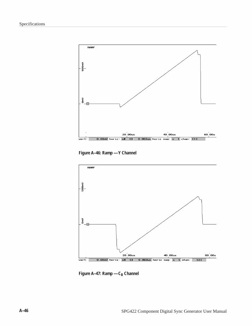
Specifications
A–46 SPG422 Component Digital Sync Generator User Manual
Figure A–46: Ramp — Y Channel
Figure A–47: Ramp — CB Channel

Specifications
SPG422 Component Digital Sync Generator User Manual A–47
Figure A–48: Ramp — CR Channel
700 mV
450 mV
110 mV
200 mV
0 mV
55 – 98
NTSCLines
PALLines
99 – 142
143 – 185
186 – 229
230 – 263
63 – 114
115 – 166
167 – 218
219 – 270
271 – 310
Figure A–49: Pluge — Y Channel

Specifications
A–48 SPG422 Component Digital Sync Generator User Manual
Figure A–50: Pluge — CB and CR Channels
Figure A–51: 40% Gray — Y Channel (B040000 and above)

Specifications
SPG422 Component Digital Sync Generator User Manual A–49
Figure A–52: 40% Gray — CB and CR Channels (B040000 and above)

Specifications
A–50 SPG422 Component Digital Sync Generator User Manual