spi ll preventi on ontrol and counterm easure l an
TRANSCRIPT
SPI LL PREVENTI ON, CONTROL , AND COUNTERM EASURE PL AN
FOR
Syr acuse Univer sity
South Campus Syracuse, New York
March 2016
SPILL PREVENTI ON, CONTROL, AND COUNTERM EASURE PL AN
for
SYRACUSE UNIVERSITY
South Campus Syracuse, New York
March 2016
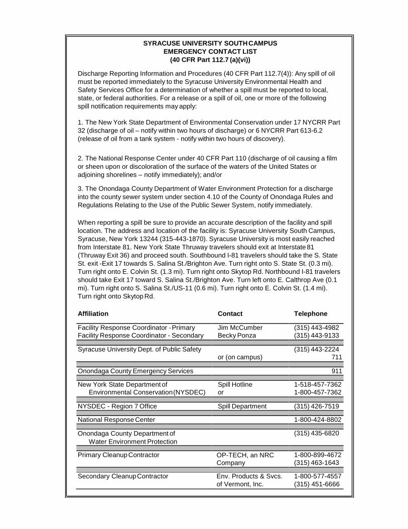
SYRACUSE UNIVERSITY SOUTH CAMPUS EMERGENCY CONTACT LIST
(40 CFR Part 112.7 (a)(vi))
Discharge Reporting Information and Procedures (40 CFR Part 112.7(4)): Any spill of oil must be reported immediately to the Syracuse University Environmental Health and Safety Services Office for a determination of whether a spill must be reported to local, state, or federal authorities. For a release or a spill of oil, one or more of the following spill notification requirements may apply:
1. The New York State Department of Environmental Conservation under 17 NYCRR Part 32 (discharge of oil – notify within two hours of discharge) or 6 NYCRR Part 613-6.2 (release of oil from a tank system - notify within two hours of discovery). 2. The National Response Center under 40 CFR Part 110 (discharge of oil causing a film or sheen upon or discoloration of the surface of the waters of the United States or adjoining shorelines – notify immediately); and/or
3. The Onondaga County Department of Water Environment Protection for a discharge into the county sewer system under section 4.10 of the County of Onondaga Rules and Regulations Relating to the Use of the Public Sewer System, notify immediately.
When reporting a spill be sure to provide an accurate description of the facility and spill location. The address and location of the facility is: Syracuse University South Campus, Syracuse, New York 13244 (315-443-1870). Syracuse University is most easily reached from Interstate 81. New York State Thruway travelers should exit at Interstate 81 (Thruway Exit 36) and proceed south. Southbound I-81 travelers should take the S. State St. exit -Exit 17 towards S. Salina St./Brighton Ave. Turn right onto S. State St. (0.3 mi). Turn right onto E. Colvin St. (1.3 mi). Turn right onto Skytop Rd. Northbound I-81 travelers should take Exit 17 toward S. Salina St./Brighton Ave. Turn left onto E. Calthrop Ave (0.1 mi). Turn right onto S. Salina St./US-11 (0.6 mi). Turn right onto E. Colvin St. (1.4 mi). Turn right onto Skytop Rd.
Affiliation Contact Telephone
Facility Response Coordinator - Primary Jim McCumber (315) 443-4982 Facility Response Coordinator - Secondary Becky Ponza (315) 443-9133 Syracuse University Dept. of Public Safety (315) 443-2224 or (on campus) 711 Onondaga County Emergency Services 911 New York State Department of Spill Hotline 1-518-457-7362
Environmental Conservation (NYSDEC) or 1-800-457-7362 NYSDEC - Region 7 Office Spill Department (315) 426-7519 National Response Center 1-800-424-8802 Onondaga County Department of
Water Environment Protection (315) 435-6820
Primary Cleanup Contractor OP-TECH, an NRC
1-800-899-4672 Company (315) 463-1643 Secondary Cleanup Contractor Env. Products & Svcs.
1-800-577-4557 of Vermont, Inc. (315) 451-6666
TABLE OF CONTENTS
Contact List......................................................................................................under front cover Applicability ................................................................................................................................ i Engineer’s Certification of Original SPCC Plan ...................................................................... ii Engineer’s Certification of Technical Amendments ................................................................ iii Review and Evaluation ............................................................................................................. iv Management Approval ............................................................................................................. vii Statement of Conformance ....................................................................................................... vii Certification of the Applicability of the Substantial Harm Criteria ................................ viii
1. FACILITY DESCRIPTION ............................................................................................. 1 A. Facility Owner and Operator ................................................................................... 1 B. Physical Layout ....................................................................................................... 1 C. Inventory of Storage Containers ............................................................................. 1 D. Discharge Prevention Measures .............................................................................. 2 E. Discharge Countermeasures .................................................................................... 2 F. Disposal Methods .................................................................................................... 3 G. Contact List ............................................................................................................. 3
2. DISCHARGE REPORTING PROCEDURES ................................................................. 4
3. DISCHARGE POTENTIAL FROM MAJOR EQUIPMENT FAILURES ..................... 6
4. CONTAINMENT AND DIVERSION STRUCTURES .................................................. 7
5. INSPECTIONS, TESTS, AND RECORDS ..................................................................... 9
6. PERSONNEL, TRAINING, AND DISCHARGE PREVENTION PROCEDURES .... 10 A. Personnel Instructions ........................................................................................... 10 B. Designated Person Accountable for Spill Prevention ........................................... 10 C. Spill Prevention Briefings ..................................................................................... 11
7. SECURITY .................................................................................................................... 12 A. Security / Control of Oil Handling, Processing, and Storage Areas ..................... 12 B. Flow Valves Locked ............................................................................................. 12 C. Starter Controls Locked ........................................................................................ 13 D. Pipeline Loading/Unloading Connections Security Capped ................................. 13 E. Lighting Adequate to Detect Spills ....................................................................... 13
8. TRUCK LOADING / UNLOADING OPERATIONS .................................................. 14 A. Secondary Containment for Transfer Vehicle ....................................................... 14 B. Warning or Barrier System for Vehicles ............................................................... 15 C. Vehicles Examined for Drainage Outlets Before Leaving .................................... 15
9. BRITTLE FRACTURE EVALUATION ....................................................................... 16
10. CONFORMANCE WITH MORE STRINGENT STATE RULES, REGULATIONS, AND GUIDELINES ..................................................................................................... 17
TABLE OF CONTENTS
11. QUALIFIED OIL-FILLED OPERATIONAL EQUIPMENT ....................................... 18
12. FACILITY DRAINAGE ASSESSMENT ..................................................................... 19 A. Use of Valves and Pumps in Diked Storage Areas ............................................... 19 B. Undiked Areas ...................................................................................................... 19 C. Facility Drainage Systems and Equipment ........................................................... 20
13. BULK STORAGE CONTAINERS ............................................................................... 21 A. Container Construction ......................................................................................... 21 B. Secondary Containment Construction ................................................................... 21 C. Secondary Containment Drainage Procedures ...................................................... 22 D. Record Keeping .................................................................................................... 22 E. Corrosion Protection for Underground and Partially Buried Containers .............. 22 F. Tank Testing Procedures ....................................................................................... 23 G. Procedures for Controlling Leakage from Internal Heating Coils ........................ 23 H. Engineering Controls to Avoid Discharges........................................................... 24 I. Inspection of Treatment Facilities ......................................................................... 24 J. Correction of Observed Discharges ...................................................................... 24 K. Locations and Construction of Mobile or Portable Containers ............................. 24
14. FACILITY TRANSFER OPERATIONS, PUMPING, AND FACILITY PROCESS ..26 A. Corrosion Protection for Buried Piping Systems ................................................ 26 B. Inspection of Exposed Piping for Buried Piping Systems .................................... 26 C. Terminal Connections at Transfer Points .............................................................. 26 D. Pipe Support Design.............................................................................................. 26 E. Regular Inspection of Aboveground Valves and Piping ....................................... 26 F. Vehicle Warning ................................................................................................... 27
15. CERTIFICATE OF THE APPLICABILITY OF THE SUBSTANTIAL HARM CRITERIA .................................................................................................................... 28
FIGURES Figures 1 – Facility Plan
TABLES Table 1 – Oil Storage Tank / Container Inventory Table 2 – Oil Storage Tank / Container and Transfer Area Fault Analysis Table 3 – SPCC Plan Review and Evaluation Documentation Table 4 – Technical Amendment Log
APPENDICES Appendix A – 40 CFR Part 112 Appendix B – Syracuse University Petroleum Bulk Storage Tank Maintenance Procedures Manual Appendix C – Inspection Forms
Syracuse University South Campus Spill Prevention, Control, and Countermeasure Plan
March 2016 - i -
Applicability
(40 CFR Part 112.1)
Under 40 CFR Part 112 (effective May 16, 2007), a Spill Prevention, Control, and Countermeasure (SPCC) Plan must be prepared when both of the following conditions apply to a facility (see Appendix A):
(i) The facility is a non-transportation-related onshore facility engaged in storing oil that
could reasonably be expected to discharge oil into or upon navigable waters the United States or adjoining shorelines; and
(ii) Excluding containers with a capacity less than 55-gallons, the facility has: (1) an
aggregate aboveground oil storage capacity of more than 1,320 gallons or (2) a total underground storage capacity not subject to all of the technical requirements of 40 CFR Part 280 or Part 281 of more than 42,000 gallons.
It should be noted that once a facility is subject to 40 CFR Part 112, oil containers at the facility with a capacity of 55-gallons or greater, that are not regulated under 40 CFR Part 280 or Part 281, are regulated by 40 CFR Part 112. The following containers are not regulated by this rule and are not included when calculating the total storage capacity for the facility:
1. Permanently closed containers; 2. Motive power containers; 3. Hot-mix asphalt containers; 4. Heating oil tanks at single family residences; 5. Pesticide application equipment / containers; 6. Milk and milk product containers, associated piping, and appurtenances; 7. Produced water container / piping as defined in 40 CFR Part 112.2 and meets
requirements in 40 CFR Part 112.9(c)(6)(i); 8. Any underground storage tank subject to all of the requirements of 40 CFR Part 280
or 281; (does not exempt associated aboveground piping and transfer areas); and 9. Intra-facility gathering lines subject to 40 CFR Parts 192 or 195.
The Syracuse University South Campus is a non-transportation-related onshore facility engaged in storing oil that could reasonably be expected to discharge oil into or upon navigable waters of the United States. The majority of stormwater on the South campus flows directly to Meadowbrook Creek. In addition, the estimated aboveground oil storage capacity of approximately 10,500 gallons, exceeds the 1,320-gallon regulatory threshold. Therefore, Syracuse University South Campus is subject to the regulatory requirements of 40 CFR 112, and as such, has prepared this Spill Prevention, Control, and Countermeasure (SPCC) Plan.
Please note that the apartment buildings located along the northern border of the South Campus (along Colvin Street), are operated by a third party and are not directly affiliated with Syracuse University. As such, these apartment buildings have not been included as part of this SPCC Plan.
Advisory to reader: Italicized text encompassed by quotation marks shown within this report indicates the regulatory language being referenced.
Syracuse University South Campus Spill Prevention, Control, and Countermeasure Plan
March 2016 - iv -
Review and Evaluation
Consistent with 40 CFR Part 112.5(b), a review and evaluation of this Spill Prevention Control and Countermeasure (SPCC) Plan is conducted at least once every five years. As a result of this review and evaluation, Syracuse University will amend the SPCC Plan within six months of the review to include more effective prevention and control technology if (1) such technology will significantly reduce the likelihood of a discharge as described in §112.1(b) from the facility, and (2) if such technology has been field-proven at the time of review. Syracuse University will amend the SPCC Plan within six (6) months of the review when:
1. There is a change in the facility design, construction, operation, or maintenance that
materially affects its potential for a discharge. Examples of changes that may require amendment of the SPCC Plan include, but are not limited to: commissioning or decommissioning containers; replacement, reconstruction, or movement of containers; reconstruction, replacement, or installation of piping systems; construction or demolition that might alter secondary containment structures; changes of product or service; or revision of standard operation or maintenance procedures at the facility.
Upon completion of the review and evaluation, SPCC regulations require documentation and signature of a statement as to whether the Plan will be amended. See Table 3 for SPCC Plan Review and Evaluation Documentation. A Professional Engineer will certify any technical amendment to the Plan consistent with 40 CFR Part 112.3(d). Technical Amendments will be logged on Table 4
Syracuse University South Campus Spill Prevention, Control, and Countermeasure Plan
March 2016 - v -
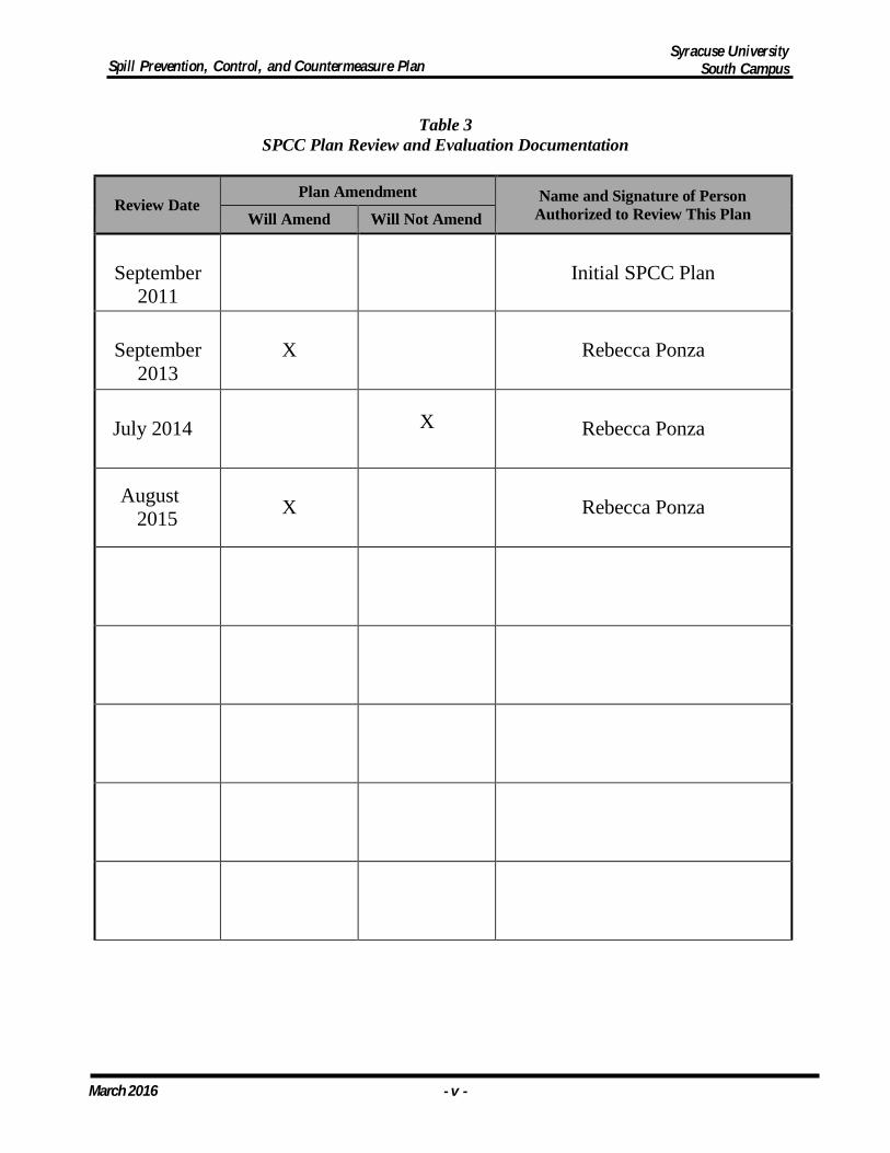
Table 3
SPCC Plan Review and Evaluation Documentation
Review Date Plan Amendment Name and Signature of Person
Authorized to Review This Plan Will Amend Will Not Amend
September
2011
Initial SPCC Plan
September
2013
X
Rebecca Ponza
July 2014
X
Rebecca Ponza
August 2015
X
Rebecca Ponza
Syracuse University South Campus Spill Prevention, Control, and Countermeasure Plan
March 2016 - vi -
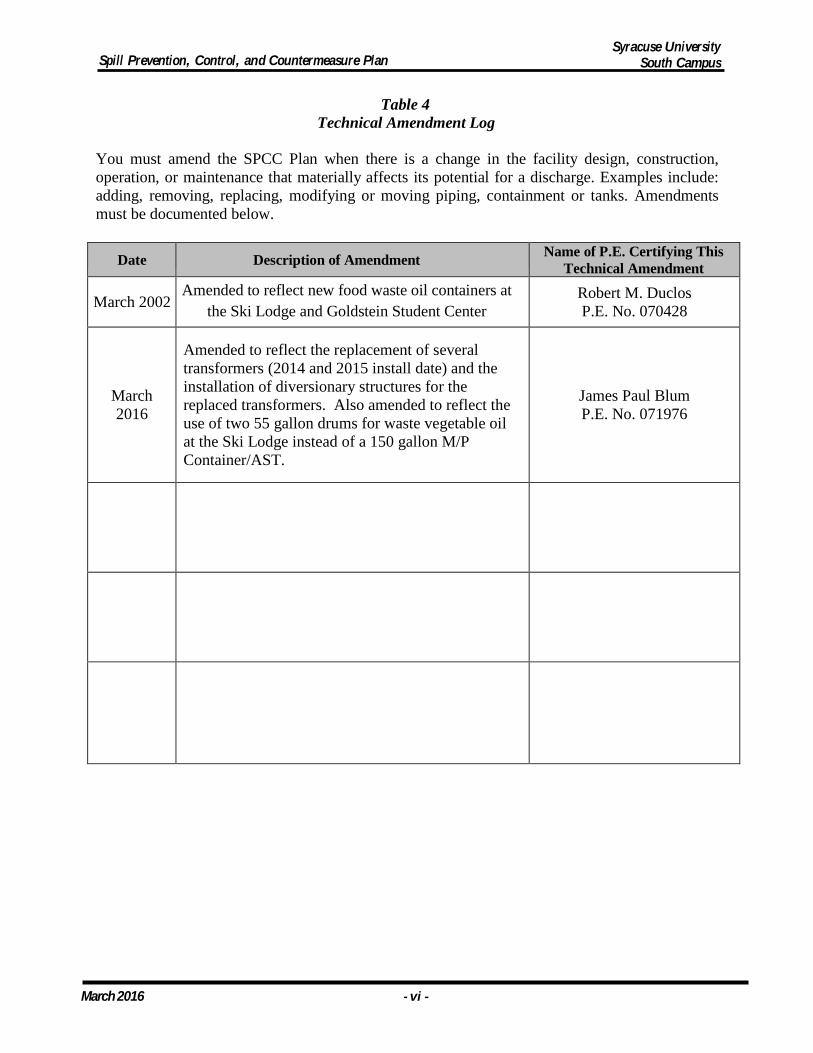
Table 4 Technical Amendment Log
You must amend the SPCC Plan when there is a change in the facility design, construction, operation, or maintenance that materially affects its potential for a discharge. Examples include: adding, removing, replacing, modifying or moving piping, containment or tanks. Amendments must be documented below.
Date Description of Amendment Name of P.E. Certifying This
Technical Amendment
March 2002 Amended to reflect new food waste oil containers at
the Ski Lodge and Goldstein Student Center Robert M. Duclos P.E. No. 070428
March 2016
Amended to reflect the replacement of several transformers (2014 and 2015 install date) and the installation of diversionary structures for the replaced transformers. Also amended to reflect the use of two 55 gallon drums for waste vegetable oil at the Ski Lodge instead of a 150 gallon M/P Container/AST.
James Paul Blum P.E. No. 071976
Syracuse University South Campus Spill Prevention, Control, and Countermeasure Plan
March 2016 - 1 -
1. FACILITY DESCRIPTION
A. Facility Owner and Operator:
(i) Facility Owner, Address, and Telephone: Syracuse University c/o Skytop Office Building Syracuse, New York 13244-5100
(ii) Facility Operator, Address, and Telephone: c/o Environmental Health and Safety Services Office 029 Lyman Hall Syracuse, New York 13244-5100
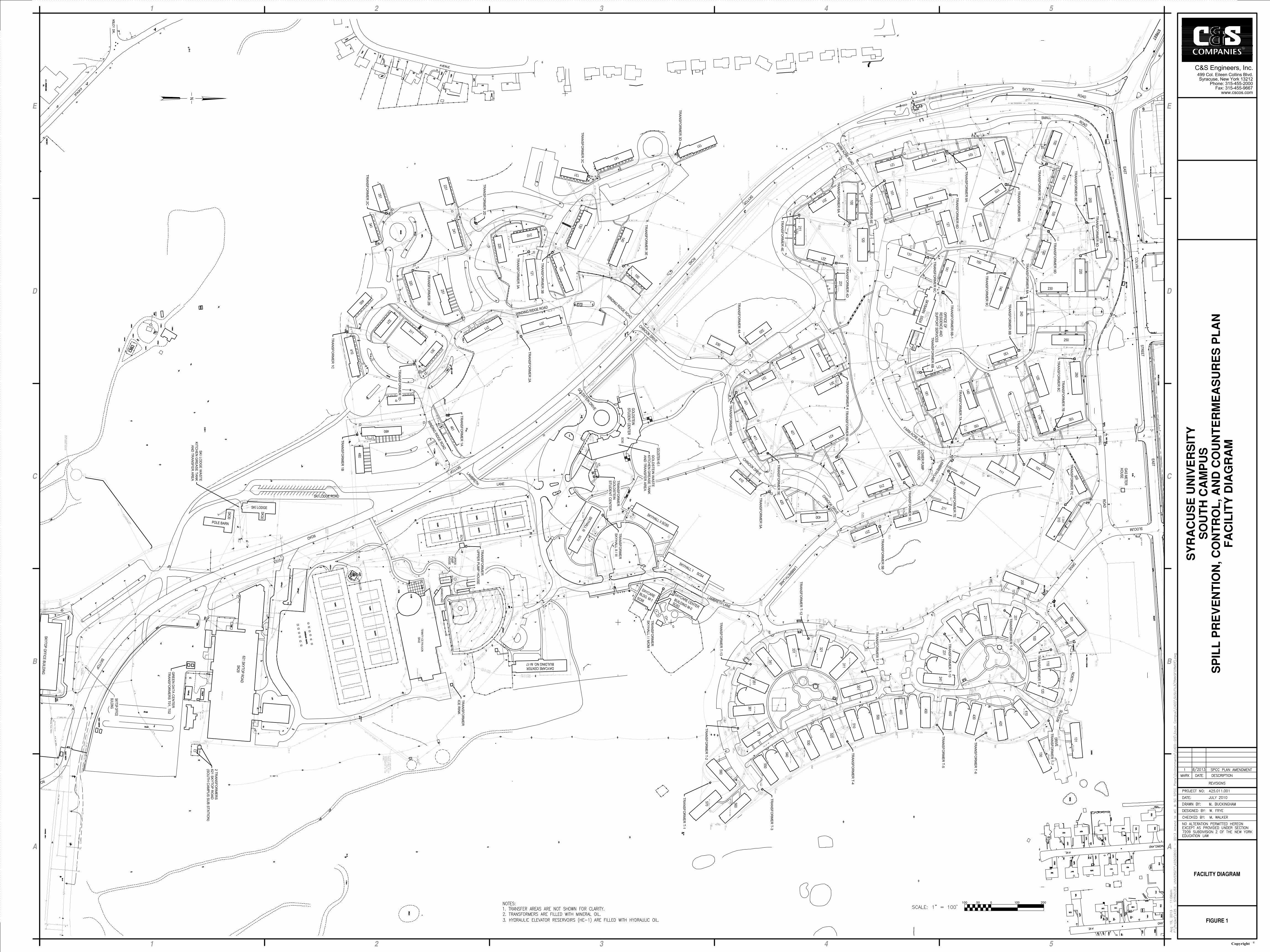
B. Physical Layout (40 CFR Part 112.7(a)(3)):
The Syracuse University South Campus (facility), located in Syracuse, New York, consists of numerous dormitories/apartments, office buildings, athletic fields and related facilities, a student center, and other physical plant structures. South Campus facilities are separated by various roads, walkways, turf areas, driveways, and parking areas. The University operates 24 hours a day, seven days a week, year round. See Figure 1 for a facility plan of the campus.
Nearly all of the oil containers at South Campus facilities are electrical transformers and hydraulic elevator reservoirs, which are defined as oil-filled operational equipment (OFOE). OFOE includes containers that have oil present solely to support the function of the device. Non-OFOE include one (1) 150-gallon mobile/portable container/AST containing used vegetable oil at Goldstein Student Center and two (2) 55-gallon mobile/portable drums containing used vegetable oil at the Ski Lodge. The facility receives oil for electrical transformers by way of specialty contractors that utilize portable drums, tank truck, and/or an oil treatment processing truck. Hydraulic elevators are typically filled via contractor-provided, portable 55-gallon drums.
C. Inventory of Storage Containers (40 CFR Part 112.7(a)(3)(i)):
This section describes types of oil product storage at the facility. It should be noted that oil is defined as “oil of any kind or in any form, including, but not limited to: fats, oils, or greases of animal, fish, or marine mammal origin; vegetable oils, including oils from seeds, nuts, fruits, or kernels; and other oils and greases, including petroleum, fuel oil, sludge, synthetic oils, mineral oils, oil refuse, or oil mixed with wastes other than dredged spoil.”
Table 1 lists oil storage containers at the facility and the products stored in each container (only those greater or equal to 55 gallons). Table 2 provides a fault analysis of the oil storage tanks / containers and transfer areas. For the purpose of this Plan, storage containers are drums, totes or tanks greater or equal to 55 gallons in size. The facility also utilizes other various oil products in lesser quantities (consumer sized containers).
Syracuse University South Campus Spill Prevention, Control, and Countermeasure Plan
March 2016 - 2 -
D. Discharge Prevention Measures (40 CFR Part 112.7(a)(3)(ii)):
(i) Routine Procedures: The only product stored at the facility that is routinely handled is used vegetable oil. Used vegetable oil at the Ski Lodge is stored in two (2) 55-gallon mobile/portable drums stored in an exterior containment shed. Used vegetable oil at the Goldstein Student Center is stored indoors in a 150-gallon mobile/portable container/AST. The containers are visually monitored when filled for overfill prevention. When nearly full, Syracuse University contracts with an outside vendor to remove the oil. This transfer is monitored by facility personnel.
Oil for electrical transformers and hydraulic elevator reservoirs are not handled on a routine basis. When required, oil is handled by personnel trained in the proper operation and maintenance of such equipment as described in Section 6 of this Plan.
(ii) Discharge or Drainage Controls (40 CFR Part 112.7(a)(3)(iii)): Table 1
indicates types of discharge or drainage controls, such as secondary containment around containers and other structures and equipment, for the control of a discharge from containers at the facility. Procedures for the control of a discharge include the following:
• Routine Procedures outlined in Section 1D(i). • Discharge Reporting Procedures outlined in Section 2. • Inspections, Tests, and Records outlined in Section 5. • Loading/Unloading Area Drainage as outlined in Section 8A. • Vehicles Examined for Drainage Outlets Before Leaving
as outlined in Section 8C.
E. Discharge Countermeasures (40 CFR Part 112.7(a)(3)(iv)): Countermeasures for discovering, responding to, and cleaning up discharges (both the facility’s capability and of those that might be required of a contractor) include the following:
(i) Discovery countermeasures include regular inspections of oil storage areas as
described in Section 5 of this Plan. Countermeasures for discharge discovery also include routine awareness by facility personnel while passing by an oil storage area.
(ii) Countermeasures used in response to a discharge are provided in the Spill
Response section of the Syracuse University Petroleum Bulk Storage Tank Maintenance Procedures Manual attached as Appendix B. Spill control equipment and materials are located on the Environmental Health and Safety Services Office service vehicle.
(iii) Countermeasures for cleanup by the facility depend on the magnitude of the
spill. The Facility Response Coordinator will determine whether the spills should be cleaned up by the facility or by an outside contractor. An outside
Syracuse University South Campus Spill Prevention, Control, and Countermeasure Plan
March 2016 - 3 -
contractor will clean up spills beyond the capability of the facility. The Facility Response Coordinator will coordinate cleanup activities with outside contractors as necessary to respond to a spill.
F. Disposal Methods (40 CFR Part 112(a)(3)(v)):
The Facility Response Coordinator will determine whether oil that has been spilled and recovered is suitable for disposal or recycling. This will depend on the condition of the recovered oil. Recovered oil will be containerized and transported to either a properly permitted, off-site, disposal or recycling facility where the material will be disposed and/or recycled in a manner consistent with applicable regulations.
G. Contact List (40 CFR Part 112.7(a)(3)(vi)):
As allowed in 40 CFR Part 112.7(a)(5), the list of contacts to notify in the event of a discharge are as shown on the inside cover of this Plan.
Syracuse University South Campus Spill Prevention, Control, and Countermeasure Plan
March 2016 - 4 -
2. DISCHARGE REPORTING PROCEDURES (40 CFR Part 112.7(a)(4))
SPCC regulations require a facility to provide information and procedures in the Plan to enable a person reporting the discharge to relate vital information regarding a discharge. Federal, state, and local discharge reporting requirements are described below.
It is the policy of Syracuse University that all oil spills (discharges) regardless of quantity, be reported to the Facility Response Coordinator at the Syracuse University Environmental Health and Safety Services Office to initiate cleanup activities and for a determination of whether a spill must be reported to local, state, and/or federal authorities. In the event the Environmental Health and Safety Services Office is not open, the person who has discovered, or the person who has knowledge of a spill, must immediately contact the Syracuse University Department of Public Safety at 711 (on-campus phones only) or (315) 443-2224. Public Safety will proceed to contact the appropriate personnel. Refer to the Contact List located in the inside cover of this Plan for contacts to notify in the event of a discharge.
40 CFR Part 110 requires any person in charge of an onshore facility with knowledge of any discharge of oil that either violates applicable water quality standards or causes a film or sheen or discoloration of the surface of the water or adjoining shorelines or cause a sludge or emulsion to be deposited beneath the surface of the water or upon adjoining shore-lines to immediately notify the National Response Center (NRC) (800-424-8802). In the event that direct reporting to the NRC is not practicable, reports may be made to the United States Coast Guard.
According to 40 CFR Part 112.4(a), whenever the facility has discharged more than 1,000 gallons of oil in a single discharge, or discharged more than 42 gallons of oil in each of two discharges occurring within any 12 month period, the EPA Regional Administrator must be notified within 60 days. Information to provide to the Regional Administrator is shown below.
A. Name of facility; B. Name of person reporting the incident; C. Location of the facility; D. Maximum storage or handling capacity of the facility and normal daily throughput; E. Corrective action and countermeasures you have taken, including a description
of equipment repairs and replacements; F. An adequate description of the facility, including maps, flow diagrams, and
topographical maps, as necessary; G. The cause of such discharge including a failure analysis of the system or subsystem
in which the failure occurred; H. Additional preventative measures you have taken or contemplated to minimize the
possibility of recurrence; and I. Such other information as the Regional Administrator may reasonably require
pertinent to the plan or discharge.
Syracuse University South Campus Spill Prevention, Control, and Countermeasure Plan
March 2016 - 5 -
In addition, New York State regulations require any person with knowledge of a discharge of petroleum to report the incident to the NYSDEC within two (2) hours of the discovery. The results of any inventory record, test, or inspection which shows a facility is leaking must also be reported to the NYSDEC within two (2) hours of discovery. Notification must be made by calling the telephone hotline (1-800-457- 7362 or 518-457-7362).
The Fire Code of New York State, specifically Chapter 34: Flammable and Combustible Liquids, contains spill reporting procedures applicable to the facility. Per Chapter 34, a consistent or accidental loss of liquid, or other indication of a leak from a tank system, shall be reported immediately to the fire department, the code enforcement official or other authorities having jurisdiction. The City of Syracuse Code Enforcement Office can be notified by calling (315) 448-8695.
The Onondaga County Department of Water Environment Protection (OCDWEP), Telephone No. 315-435-2260, must also be notified immediately upon discharging wastes into the County sewer system in violation of the County of Onondaga Rules and Regulations Relating to the Use of the Public Sewer System.
Syracuse University South Campus Spill Prevention, Control, and Countermeasure Plan
March 2016 - 6 -
3. DISCHARGE POTENTIAL FROM MAJOR EQUIPMENT FAILURES
As required by 40 CFR Part 112.7(b), “Where experience indicates a reasonable potential for equipment failure (such as loading or unloading equipment, tank overflow, rupture, or leakage or any other equipment known to be a source of a discharge), the plan should include a prediction of the direction, rate of flow, and total quantity of oil which could be discharged from the facility as a result of each major type of failure.”
Table 2 (attached to the Plan) indicates potential spill directions, volumes, rates, and controls for oil storage tanks / containers and transfer areas at the facility. The total quantity of oil that could be discharged from the facility is based on a worst-case situation for bulk oil storage containers and on the typical failure mode for transfer areas and oil- filled operational equipment (OFOE). The spill direction is based on the most obvious spill pathway. These tables do not take into account the time it would take to respond to a spill (e.g., lifting a tipped drum, or closing a valve), that could greatly reduce the quantity discharged.
Syracuse University South Campus Spill Prevention, Control, and Countermeasure Plan
March 2016 - 7 -
4. CONTAINMENT AND DIVERSION STRUCTURES
Drainage Control Diversionary Structures and Containment: According to 40 CFR Part 112.7(c), “Provide appropriate containment and/or diversionary structures or equipment to prevent a discharge described in §112.1(b), except as provided in paragraph (k) of this section for qualified oil-filled operational equipment, and except as provided in §112.9(d)(3) for flowlines and intrafacility gathering lines at an oil production facility. The entire containment system, including walls and floor, must be capable of containing oil and must be constructed so that any discharge from a primary containment system, such as a tank, will not escape the containment system before clean up occurs. In determining the method, design, and capacity for secondary containment, you need only to address the typical failure mode, and the most likely quantity of oil that would be discharged. Secondary containment may be either active or passive in design. At a minimum, you must use one of the following prevention systems or its equivalent:”
• Dikes, berms, or retaining walls sufficiently impervious to contain oil; • Curbing or drip pans; • Sumps and collection systems; • Culverting, gutters, or other drainage systems; • Weirs, booms, or other barriers; • Spill diversion ponds; • Retention ponds; or • Sorbent materials.
Table 1 indicates the type of containment system for each oil storage container while Table 2 provides a fault analysis of oil tanks / containers and transfer areas at the facility. The tables indicate secondary containment implemented, and / or maintained to meet the standard of sufficiently impervious. As shown in Table 2, a fault analysis was prepared for bulk oil storage tanks / containers based on worst case scenario, while the fault analysis for transfer areas and OFOE was based on typical failure mode.
Oil-filled operational equipment includes hydraulic elevator reservoirs and electrical transformers. These items are required to have general secondary containment (a.k.a. appropriate containment) consistent with §112.7(c). The 150-gallon used vegetable oil mobile/portable containers/AST and the 55-gallon used vegetable oil drums are required to have sized secondary containment consistent with §112.8(c). The used vegetable oil mobile/portable containers/AST and drums are addressed in Section 13 of this Plan. Locations of outdoor electrical transformers are shown on Figure 1.
The two (2) hydraulic elevator reservoirs are located indoors within rooms of existing buildings that have floors and walls that serve as secondary containment. The floor drain located near the elevator reservoir in the Skytop Office Building has been permanently plugged to prevent a discharge to the environment. These provisions exceed the appropriate containment standard.
Syracuse University South Campus Spill Prevention, Control, and Countermeasure Plan
March 2016 - 8 -
To determine whether an electrical transformer was appropriately contained, it was evaluated for numerous factors, including the following:
• Construction: whether the transformer was situated on a concrete pad; or
surrounded by crushed stone; or surrounded by concrete curbing; etc. • Condition of construction: concrete cracks and/or settlement; weeds in stone
areas; etc. • Date of transformer installation. • Distance, slope, and terrain to the nearest drainage inlet or other storm water
conveyance system. • Evidence of oil stains and/or corrosion on the exterior of the container. • Properties of the oil utilized in the transformer (i.e. flashpoint, biodegradability, etc.)
Based on the above evaluation, the 67 electrical transformers were classified as “Appropriately Contained/No further Action.” These transformers are classified as appropriately contained consistent with §112.7(c). They are constructed and/or located such that the lateral migration of oil in the event of a spill may be cleaned up before becoming a discharge. These transformers appear to be in good physical condition and are constructed and/or located consistent with one or more of the following characteristics:
• The transformer is constructed with crushed stone and concrete curbing that
surrounds the container; • There is no readily apparent drainage inlet near the transformer; • The nearest drainage inlet is located a long distance (a minimum of 120 ft)
from a drainage inlet; and/or • The terrain between the transformer and drainage inlet may provide
appropriate containment.
With regard to oil-filled electrical transformers, it should be noted that a drop in oil level can cause the device to fail, which could disrupt power to a building. This could lead to the discovery of a spill before it becomes a discharge that leaves the site.
Transfer area and bulk storage tank containment systems are discussed in Section 8 and Section 13 of this Plan, respectively. Undiked areas are discussed in Section 12.
As provided in 40 CFR Part 112.7(d), if it is determined that the installation of any of the structures or pieces of equipment listed to prevent discharged oil from reaching the navigable waters is not practicable, the owner or operator should clearly explain such impracticability and in the case of bulk storage containers, conduct both periodic integrity testing of the containers and periodic integrity and leak testing of the valves and piping, and provide the following:
• An Oil Spill Contingency Plan following the provision of 40 CFR Part 109.
• A written commitment of manpower, equipment, and materials required to expeditiously control and remove any quantity of oil discharged that may be harmful.
Syracuse University South Campus Spill Prevention, Control, and Countermeasure Plan
March 2016 - 9 -
5. INSPECTIONS, TESTS, AND RECORDS
40 CFR Part 112.7(e) states “Conduct inspections and tests required by this part in accordance with written procedures that you or the certifying engineer develop for the facility. You must keep these written procedures and a record of the inspections and tests, signed by the appropriate supervisor or inspector, with the SPCC Plan for a period of three years. Records of inspections and tests kept under usual and customary business practices will suffice for purposes of this paragraph.”
The written procedures for conducting inspections and tests associated with SPCC maintenance are described in this and other sections of this Plan. A record of the inspections and tests, signed by the appropriate supervisor or inspector, are maintained with this Plan for a minimum of three years. Inspections include annual audits of bulk storage containers, outdoor electrical transformers, and hydraulic elevator reservoirs as well as monthly inspections of bulk storage containers. In addition the University also conducts a review of this SPCC plan on an annual basis.
Syracuse University South Campus Spill Prevention, Control, and Countermeasure Plan
March 2016 - 10 -
6. PERSONNEL, TRAINING, AND DISCHARGE PREVENTION PROCEDURES
A. Personnel Instructions:
40 CFR Part 112.7(f)(1) states “At a minimum, train your oil-handling personnel in the operation and maintenance of equipment to prevent discharges; discharge procedure protocols; applicable pollution control laws, rules, and regulations; general facility operations; and, the contents of the facility SPCC Plan.”
Training for oil-handling personnel at the facility (i.e. Physical Plant, Housing, Public Safety, Food Service, etc.) is provided following an individual’s placement into positions associated with oil storage, transfer, or utilization, and includes:
• Operation and maintenance of equipment to prevent discharges; • Routine procedures to be followed to minimize the potential for discharges
(including use of sorbent materials or barriers to mitigate migration across surfaces, use of drain blocking pads to prevent a spill from entering a drainage inlet, use of booms to contain spills into surface water, and use of pumps to remove oil from surface water or containment areas);
• Procedures to be followed in the event of a discharge; • Applicable pollution control laws, rules, and regulations; • General facility operations; and • The contents of the facility SPCC Plan.
Additional training is provided to employees whose oil-handling responsibilities change during the course of their employment, to the extent that such additional training is required based on the change of responsibilities.
With the exception of the used vegetable oil mobile/portable containers/AST and used vegetable oil drums, oil containers at the facility are either electrical transformers or hydraulic elevator reservoirs. Syracuse University utilizes specialty contractors for maintenance activities that involve oil-handling of this equipment. The University requires the specialty contractor’s site representatives to be trained on the proper operation and maintenance of such equipment to prevent a discharge.
B. Designated Person Accountable for Spill Prevention:
40 CFR Part 112.7(f)(2) states “Designate a person at each applicable facility who is accountable for discharge prevention and who reports to facility management.” As indicated in the Emergency Contact List (located inside the front cover of this Plan), the Syracuse University Director of the Environmental Health and Safety Services (EHSS) Office is the primary individual accountable for discharge prevention and who will report to facility management. Specifically, the Director of EHSS will ensure the facility personnel are trained, understand and follow the spill response and prevention procedures outlined in this plan. The Director of EHSS will also verify that inspections are being conducted and will be the person contacting appropriate agencies in the event of a spill.
Syracuse University South Campus Spill Prevention, Control, and Countermeasure Plan
March 2016 - 11 -
C. Spill Prevention Briefings:
40 CFR Part 112.7(f)(3) states “Schedule and conduct discharge prevention briefings for your oil-handling personnel at least once a year to assure adequate understanding of the SPCC Plan for that facility. Such briefings must highlight and describe known discharges as described in §112.1(b) or failures, malfunctioning components, and any recently developed pre-cautionary measures.”
Discharge prevention briefings for oil-handling personnel are held at least once a year to assure adequate understanding of the SPCC Plan for the facility. These briefings highlight and describe known discharges or equipment failures, malfunctioning components, and recently developed precautionary measures.
Syracuse University South Campus Spill Prevention, Control, and Countermeasure Plan
March 2016 - 12 -
7. SECURITY
40 CFR Part 112.7(g)(1) states: “Describe in your Plan how you secure and control access to the oil handling, processing and storage areas; secure master flow and drain valves; prevent unauthorized access to starter controls on oil pumps; secure out-of-service and loading / unloading connections of oil pipelines; and address the appropriateness of security lighting to both prevent acts of vandalism and assist in the discovery of oil discharges.”
A. Security / Control of Oil Handling, Processing and Storage Areas:
Indoor hydraulic elevator reservoirs are located in locked mechanical or electrical rooms inside of existing buildings or other areas that are only accessible to facility personnel. In these areas, equivalent environmental protection (regarding security) to prevent a discharge is provided by the physical barriers imposed by the locked rooms which deter vandalism and prevent unauthorized access to containers and equipment that could be involved in an oil discharge.
Electrical transformers are not fully fenced because fencing them would visually impair the aesthetics of the campus that the University strives for. Equivalent environmental protection (regarding security) to prevent a discharge from outdoor containers is achieved via periodic monitoring by facility staff and routine patrols by Syracuse University Department of Public Safety. In addition, several containers are located in areas equipped with area lighting to minimize vandalism and enhance monitoring.
A 150-gallon mobile/portable containers/AST containing used vegetable oil is located at the Goldstein Student Center in an area that is frequently monitored by facility staff and the mobile / portable AST’s lid is kept locked. The two 55-gallon drums containing used vegetable oil at the Ski Lodge are also in an area that is frequently monitored by facility staff
B. Flow Valves Locked:
40 CFR Part 112.7(g)(2) states “Ensure that the master flow and drain valves and any other valves permitting direct outward flow of the container’s contents to the surface have adequate security measures so that they remain in the closed position when in non-operating or non-standby status.”
Master flow and drain valves and any other valves permitting direct outward flow of an oil container’s contents to the surface are equipped with security measures so that they remain in the closed position when in non-operating or non-standby status.
Syracuse University South Campus Spill Prevention, Control, and Countermeasure Plan
March 2016 - 13 -
C. Starter Controls Locked:
40 CFR Part 112.7(g)(3) states “Lock the starter control on each oil pump in the “off” position and locate it at a site accessible only to authorized personnel when the pump is in a non-operating or non-standby status.”
The starter control on each hydraulic elevator oil pumping system at the facility is locked in the “off” position and located at a site accessible only to authorized personnel when the pump is in a non-operating or non-standby status. Other oil containers at the facility are not equipped with oil pumps or starter controls.
D. Pipeline Loading/Unloading Connections Securely Capped:
40 CFR Part 112.7(g)(4) states “Securely cap or blank-flange the loading/ unloading connections of oil pipelines or facility piping when not in service or when in standby service for an extended time. This security practice also applies to piping that is emptied of liquid content either by draining or by inert gas pressure.”
There are no facility piping loading/unloading connections at the facility.
E. Lighting Adequate to Detect Spills:
40 CFR Part 112.7(g)(5) states “Provide facility lighting commensurate with the type and location of the facility that will assist in the:
(i) Discovery of discharges occurring during hours of darkness, both by operating
personnel, if present, and by non-operating personnel (the general public, local police, etc.); and
(ii) Prevention of discharges occurring through acts of vandalism.”
Existing lighting systems are appropriate for the type and location of the oil storage containers at the Syracuse University South Campus.
Syracuse University South Campus Spill Prevention, Control, and Countermeasure Plan
March 2016 - 14 -
8. TRUCK LOADING / UNLOADING OPERATIONS
A. Secondary Containment for Transfer Vehicles:
40 CFR Part 112.7(h)(1) states “Where loading / unloading rack drainage does not flow into a catchment basin or treatment facility designed to handle discharges, use a quick drainage system for tank car or tank truck loading / unloading racks. You must design any containment system to hold at least the maximum capacity of any single compartment of a tank car or tank truck loaded or unloaded at the facility.”
A loading rack is a fixed structure (such as a gangway or platform) which typically includes a loading or unloading arm, and may include a combination of piping assemblages, valves, pumps, shut-off devices, overfill sensors, or personnel safety devices, for the filling of bulk oil vehicles (e.g. tanker trucks). The facility does not have a loading rack. However, the requirements of 40 CFR Part 112.7(c) requiring appropriate containment do apply to the following areas where oil is transferred to / from bulk oil storage containers and OFOE:
Used Vegetable Oil Mobile/Portable Containers/ASTs The area where oil is p o u r e d a n d / o r pumped i n t o a n d out of the facility’s 150-gallon used vegetable oil mobile/portable container/AST is considered a transfer area and is required to be appropriately contained. Likewise, the area where oil is poured into the facility’s 55-gallon used vegetable oil drums is considered a transfer area and is required to be appropriately contained. The University requires food service employees and contractors to be prepared to deploy active containment in the event of a spill during an oil transfer operation. Active containment measures include the capability to implement one or more of the following: placement of a drain protector over a drainage inlet; placement of an oil absorbing boom between the transfer operation and floor drain; deployment of a containment pallet or portable containment dike beneath the transfer operation; and/or deployment of oil-absorbing materials on spilled product (e.g., pads, speedi-dry, etc.). The transfer areas for used vegetable oil are shown on Figure 1 and detailed in Table 2. Electrical Transformers As noted in Section 1B, oil is transferred to/from electrical transformers by way of specialty contractors that utilize mobile/portable drums, tank truck, and/or an oil treatment processing truck. The University requires the specialty contractor to be prepared to deploy active containment in the event of a spill during an oil transfer operation. Active containment measures include the capability to implement one or more of the following: placement of a drain protector over a drainage inlet cover; placement of oil absorbing boom between the transfer operation and a down-gradient drainage inlet; deployment of a portable containment dike beneath the transfer operation; and/or deployment of oil-absorbing materials on spilled product (e.g., pads, speedy-dry, etc.).
Syracuse University South Campus Spill Prevention, Control, and Countermeasure Plan
March 2016 - 15 -
Hydraulic Elevators
Similarly, the areas where oil is transferred to/from hydraulic elevator reservoirs are considered transfer areas and are required to be appropriately contained. The University requires the specialty contractor to be prepared to deploy active containment in the event of a spill during an oil transfer operation. Active containment measures include the capability to implement one or more of the following: placement of a drain protector over a drainage inlet; placement of an oil absorbing boom between the transfer operation and floor drain; deployment of a containment pallet or portable containment dike beneath the transfer operation; and/or deployment of oil-absorbing materials on spilled product (e.g., pads, speedi-dry, etc.).
B. Warning or Barrier System for Vehicles:
40 CFR Part 112.7(h)(2) states “Provide an interlocked warning light or physical barrier system, warning signs, wheel chocks, or vehicle break interlock system in loading/unloading racks to prevent vehicles from departing before complete disconnection of flexible or fixed oil transfer lines.”
There are no loading racks at the University. However, the University requires oil- handling specialty contractors to utilize wheel chocks on tank trucks to prevent vehicles from departing before complete disconnection of oil transfer lines.
C. Vehicles Examined for Drainage Outlets before Leaving:
40 CFR Part 112.8(h)(3) states “Prior to filling and departure of any tank car or tank truck, closely inspect for discharges the lowermost drain and all outlets of such vehicles, and if necessary, ensure that they are tightened, adjusted, or replaced to prevent liquid discharge while in transit.”
Facility personnel are periodically present during the oil transfer process, which is continually staffed and monitored by the oil supply vendor. Facility personnel are trained in the proper procedures for verifying and documenting conditions before, during, and after each transfer activity. Tank truck drains are inspected for discharges before departing the site.
Syracuse University South Campus Spill Prevention, Control, and Countermeasure Plan
March 2016 - 16 -
9. BRITTLE FRACTURE EVALUATION
40 CFR Part 112.7(i) states “If a field-constructed aboveground container undergoes a repair, alteration, reconstruction, or a change in service that might affect the risk of a discharge or failure due to brittle fracture or other catastrophe, or has discharged oil or failed due to brittle fracture failure or other catastrophe, evaluate the container for risk of discharge or failure due to brittle fracture or other catastrophe, and as necessary, take appropriate action.”
There are no field-constructed aboveground containers at the facility.
Syracuse University South Campus Spill Prevention, Control, and Countermeasure Plan
March 2016 - 17 -
10. CONFORMANCE WITH MORE STRINGENT STATE RULES, REGULATIONS, AND GUIDELINES
In addition to the minimal prevention standards listed under 40 CFR Part 112.7(c), 40 CFR Part 112.7(j) states “include in your Plan a complete discussion of confor- mance with the applicable requirements and other effective discharge prevention and containment procedures listed in this part or any applicable more stringent State rules, regulations, and guidelines.”
The discharge prevention and containment procedures implemented by this facility have been designed to conform to the applicable requirements of 40 CFR Part 112, as well as other applicable more stringent state rules, regulations, and guidelines as described below and in separate paragraphs within this Plan..
NYSDEC Petroleum Bulk Storage Regulations:
The NYSDEC Petroleum Bulk Storage (PBS) regulations (6 NYCRR Parts 613, dated October 11, 2015) regulate the registration, handling and storage, and standards for new and substantially modified petroleum storage tanks in New York State. The PBS rule applies to all aboveground and underground storage facilities with a combined capacity over 1,100 gallons of petroleum. This rule only applies to stationary tanks / containers, but it does not have a de minimis capacity threshold. 6 NYCRR Part 613-1.3(as) defines petroleum as “crude oil and any fraction thereof, synthetic forms of lubricating oils, dielectric oils, insulating oils, hydraulic oils, and cutting oils, any complex blend of hydrocarbons that is not derived from crude oil, or any petroleum mixture.” The PBS rule does not apply to operational tank systems which are defined in 6 NYCRR Part 613-1.3(an) as “a tank system that is integral to, or connected to, equipment or machinery for which the petroleum in the system is used solely for operational purposes. Petroleum in an operational tank system is not consumed in any context (such as being combusted as fuel or used as a raw material in a manufacturing process). Examples of operational tank systems include hydraulic lift tank systems, lubricating oil system reservoirs, electrical cable oil reservoirs, and electrical transformers.”
Syracuse University South Campus Spill Prevention, Control, and Countermeasure Plan
March 2016 - 18 -
11. QUALIFIED OIL-FILLED OPERATIONAL EQUIPMENT
40 CFR Part 112.7(k) states “The owner or operator of a facility with oil-filled operational equipment that meets the qualification criteria in paragraph (k)(1) of this sub-section may choose to implement for this oil-filled operational equipment the alternate requirements as described in paragraph (k)(2) of this sub-section in lieu of general secondary containment required in paragraph (c) of this section.”
To qualify, the facility must not have had a single discharge from any oil-filled operational equipment exceeding 1,000 gallons or two discharges from any oil-filled operational equipment exceeding 42 gallons within any 12 month period in the three years prior to the SPCC Plan certification date, or since becoming subject to this part if the facility has been in operation for less than three years; and if the secondary containment is not provided for consistent with 40 CFR Part 112.7(c), the owner or operator of a facility with oil-filled operational equipment must:
1. Establish and document the facility procedures for inspections or monitoring
program to detect equipment failure and/or a discharge; and 2. Unless a Facility Response Plan has been submitted consistent with 40 CFR Part
112.20, provide in the Plan the following: a) An oil spill contingency plan consistent with 40 CFR Part 109; and b) A written commitment of manpower, equipment, and materials required to
expeditiously control and remove any quantity of oil discharged.
As noted above, Syracuse University has decided to implement appropriate secondary containment for oil-filled operational equipment.
Syracuse University South Campus Spill Prevention, Control, and Countermeasure Plan
March 2016 - 19 -
12. FACILITY DRAINAGE ASSESSMENT
A. Use of Valves and Pumps in Diked Storage Areas:
40 CFR Part 112.8(b)(1) states “Restrain drainage from diked storage areas by valves to prevent a discharge into the drainage system or facility effluent treatment system, except where facility systems are designed to control such discharge. You may empty diked areas by pumps or ejectors; however, you must manually activate these pumps or ejectors and must inspect the condition of the accumulation before starting, to ensure no oil will be discharged.”
In addition, 40 CFR Part 112.8(b)(2) states “Use valves of manual, open-and-closed design, for the drainage of diked areas. You may not use flapper-type drain valves to drain diked areas. If your facility drainage drains directly into a watercourse and not into an on-site wastewater treatment plant, you must inspect and may drain uncontaminated retained stormwater, as provided in paragraphs (c)(3)(ii), (iii), and (iv) of this section.”
There are no oil containers at the facility that utilize a dike-style containment system.
B. Undiked Areas:
40 CFR Part 112.8(b)(3) states “Design facility drainage systems from undiked areas with a potential for a discharge (such as where piping is located outside containment walls or where tank truck discharges may occur outside the loading area) to flow into ponds, lagoons, or catchment basins designed to retain oil or return it to the facility. You must not locate catchment basins in areas subject to periodic flooding.”
In addition, 40 CFR Part 112.8(b)(4) states “If facility drainage is not engineered as in paragraph (b)(3) of this section, equip the final discharge of all ditches inside the facility with a diversion system that would, in the event of an uncontrolled discharge, retain oil in the facility.”
Areas at the facility where tank truck discharges may occur outside a contained area are not designed for drainage to flow into containment ponds, lagoons, or catchment basins or to return it to the facility. Most of these areas are related to the infrequent transfer of oil to/from an electrical transformer or the 150-gallon used vegetable oil mobile/portable container/AST or the 55-gallon used vegetable oil mobile/portable drums. As described in Section 8A, active containment measures are capable of being deployed during oil transfers to prevent spills from occurring to provide equivalent environmental protection.
Due to the facility layout, relatively low volumes of oil transferred, and infrequent deliveries and transfers of oil products, it is not practical to construct facility drainage from undiked areas to flow into ponds, lagoons, or catchment basins designed to retain oil or return it to the facility. To provide additional equivalent environmental protection, the facility has several measures in place to prevent a discharge as described in Section 1D(ii).
Syracuse University South Campus Spill Prevention, Control, and Countermeasure Plan
March 2016 - 20 -
C. Facility Drainage Systems and Equipment:
40 CFR Part 112.8(b)(5) states “Where drainage waters are treated in more than one treatment unit and such treatment is continuous, and pump transfer is needed, provide two ‘‘lift’’ pumps and permanently install at least one of the pumps. Whatever techniques you use, you must engineer facility drainage systems to prevent a discharge as described in §112.1(b) in case there is an equipment failure or human error at the facility.”
Facility drainage discharges into the Onondaga County Department of Water Environment Protection combined sewer overflow system. There is no onsite treatment of facility drainage and is therefore this requirement is not applicable. The majority of stormwater discharges to Meadowbrook Creek.
Syracuse University South Campus Spill Prevention, Control, and Countermeasure Plan
March 2016 - 21 -
13. BULK STORAGE CONTAINERS
A. Container Construction:
40 CFR Part 112.8(c)(1) states “Not use a container for the storage of oil unless its material and construction are compatible with the material stored and conditions of storage such as pressure and temperature.”
The material and construction of bulk storage containers at the facility are compatible with the material stored and conditions of storage. Table 1 generally describes container construction for bulk storage containers and oil-filled operational equipment at the facility.
It is believed that the standard of construction of 55-gallon drums is consistent with United States Department of Transportation requirements. The construction of the 150-gallon mobile/portable container/AST is not per an industry standard. However, they are constructed of a material compatible with the substance stored and are approved by the Syracuse Fire Department.
It is believed that the standard of construction of oil-filled operational equipment is consistent with the following industry standards:
• Hydraulic elevators – ANSI A17.1. • Electrical transformers – ANSI C57.12.26, ANSI C57.12.28, IEEE 386,
and/or IEEE C57.12.00.
B. Secondary Containment Construction:
40 CFR Part 112.8(c)(2) states “Construct all bulk storage tank installations (except mobile refuelers and other non-transportation-related tank trucks) so that you provide a secondary means of containment for the entire capacity of the largest single container and sufficient freeboard to contain precipitation. You must ensure that diked areas are sufficiently impervious to contain discharged oil. Dikes, containment curbs, and pits are commonly employed for this purpose. You may also use an alternative system consisting of a drainage trench enclosure that must be arranged so that any discharge will terminate and be safely confined in a facility catchment basin or holding pond.”
There are only two bulk storage container locations at the facility; one (1) 150-gallon used vegetable oil mobile/portable containers/ASTs, situated inside the Goldstein Student Center and two (2) 55-gal lon used vegetable oi l d rums located outside of the Ski Lodge. Secondary containment for the 150-gal lon mobile/portable containers/ASTs is provided via double-wall construction. Secondary containment for the 55-gallon drums is provided by a covered containment shed.
Syracuse University South Campus Spill Prevention, Control, and Countermeasure Plan
March 2016 - 22 -
C. Secondary Containment Drainage Procedures:
40 CFR Part 112.8(c)(3) states “Not allow drainage of uncontaminated rainwater from the diked area into a storm drain or discharge of an effluent into an open watercourse, lake, or pond, bypassing the facility treatment system unless you:
(i) Normally keep the bypass valve sealed closed. (ii) Inspect the retained rainwater to ensure that its presence will not cause a
discharge as described in §112.1(b). (iii) Open the bypass valve and reseal it following drainage under respon-sible
supervision; and (iv) Keep adequate records of such events”.
There are no secondary containment structures at the facility that are exposed to or collect stormwater.
D. Recordkeeping:
As noted above, 40 CFR Part 112.8(c)(3)(iv) requires adequate records of dike drainage events be maintained. In addition, any records required under permits issued in accordance with §§122.41(j)(2) and 122.41(m)(3) of this chapter might be applicable (i.e., SPDES Permit).
This section is not applicable to the facility.
E. Corrosion Protection for Underground and Partially Buried Containers:
40 CFR Part 112.8(c)(4) states “Protect any completely buried metallic storage tank installed on or after January 10, 1974, from corrosion by coatings or cathodic protection compatible with local soil conditions. You must regularly leak test such completely buried metallic storage tanks.”
Underground storage tanks (UST) for purposes of SPCC are defined as completely buried, unlike “underground storage tanks” in EPA’s UST program (40 CFR Part 280), which may be partially buried.
There are no known completely buried metallic storage tanks installed on or after January 10, 1974 at the facility to which 40 CFR Part 112 is applicable.
Corrosion Protection of Partially Buried Metallic Tanks: 40 CFR Part 112.8(c)(5) states “Not use partially buried or bunkered metallic tanks for the storage of oil, unless you protect the buried section of the tank from corrosion. You must protect partially buried and bunkered tanks from corrosion by coatings or cathodic protection compatible with local soil conditions.”
There are no known partially buried tanks at the facility.
Syracuse University South Campus Spill Prevention, Control, and Countermeasure Plan
March 2016 - 23 -
F. Tank Testing Procedures:
40 CFR Part 112.8(c)(6) states “Test or inspect each aboveground container for integrity on a regular schedule, and whenever you make material repairs. You must determine, in accordance with industry standards, the appropriate qualifications for personnel performing tests and inspections, the frequency and type of testing and inspections, which take into account container size, configuration, and design (such as containers that are shop-built, field-erected, skid mounted, elevated, equipped with a liner, double-walled, or partially buried). Examples of these integrity tests include, but are not limited to: visual inspection, hydrostatic testing, radiographic testing, ultrasonic testing, acoustic emissions testing, or other systems of non-destructive testing. You must keep comparison records and you must also inspect the container’s supports and foundations. In addition, you must frequently inspect the outside of the container for signs of deterioration, discharges, or accumulation of oil inside diked areas. Records of inspections and tests kept under usual and customary business practices satisfy the recordkeeping requirements of this paragraph.” This portion of the regulation does not apply to OFOE since they are not considered bulk storage containers.
The industry standard document: Steel Tank Institute (STI) Standard SP-001 (Standard for Inspection of Aboveground Storage Tanks) as well as good engineering practices were considered to determine the appropriate inspection scope and frequency for the 55-gallon drums and 150-gallon used vegetable oil mobile/portable container/AST.
The containers have spill control (secondary containment) and continuous release detection methods (impervious underlayment, secondary containment and / or elevated). Under SP-001 the tanks / containers are considered Category 1 Tanks and require monthly inspection. The personnel performing these inspections are knowledgeable of storage facility operations, characteristics of the liquid stored, the type of tank and its associated components. The university inspection form is attached as Appendix G.
G. Procedures for Controlling Leakage From Internal Heating Coils:
40 CFR Part 112.8(c)(7) states “Control leakage through defective internal heating coils by monitoring the steam return and exhaust lines for contamination from internal heating coils that discharge into an open watercourse, or pass the steam return or exhaust lines through a settling tank, skimmer, or other separation or retention system.”
Internal heating coils are not utilized by the facility.
Syracuse University South Campus Spill Prevention, Control, and Countermeasure Plan
March 2016 - 24 -
H. Engineering Controls to Avoid Discharges:
40 CFR Part 112.8(c)(8) states “Engineer or update each container installation in accordance with good engineering practice to avoid discharges. You must provide at least one of the following devices:
(i) High liquid level alarms with an audible or visual signal at a constantly
attended operation or surveillance station. In smaller facilities an audible air vent may suffice.
(ii) High liquid level pump cutoff devices set to stop flow at a pre-determined container content level.
(iii) Direct audible or code signal communication between the container gauger and the pumping station.
(iv) A fast response system for determining the liquid level of each bulk storage container such as digital computers, telepulse, or direct vision gauges. If you use this alternative, a person must be present to monitor gauges and the overall filling of bulk storage containers.
(v) You must regularly test liquid level sensing devices to ensure proper operation.”
Table 1 lists specific engineering controls (i.e., overfill protection) utilized for each oil storage container at the facility.
I. Inspection of Treatment Facilities:
40 CFR Part 112.8(c)(9) states “Observe effluent treatment facilities frequently enough to detect possible system upsets that could cause a discharge as described in §112.1(b).”
There are no effluent treatment facilities at the site.
J. Correction of Observed Discharges:
40 CFR Part 112.8(c)(10) states “Promptly correct visible discharges which result in a loss of oil from the container, including but not limited to seams, gaskets, piping, pumps, valves, rivets, and bolts. You must promptly remove any accumulations of oil in diked areas.”
Visible discharges are promptly corrected.
K. Locations and Construction of Mobile or Portable Containers:
40 CFR Part 112.8(c)(11) states “Position or locate mobile or portable oil storage containers to prevent a discharge as described in §112.1(b). You must furnish a secondary means of containment, such as a dike or catchment basin, sufficient to contain the capacity of the largest single compartment or container with sufficient freeboard to contain precipitation.”
Syracuse University South Campus Spill Prevention, Control, and Countermeasure Plan
March 2016 - 25 -
Table 1 identifies mobile and/or portable bulk storage containers and describes containment for these containers.
Due to the nature of facility operations, it is possible that additional mobile / portable containers (e.g., 55-gallon drums, portable tanks, portable generators, etc.) will be brought on-site by the University to accommodate facility operations, or by outside contractors during construction projects.
Syracuse University will coordinate with outside contractors that propose to bring containers on-site to ensure that the containers meet the requirements of 40 CFR Part 112 by either complying with this SPCC Plan or by providing their own SPCC Plan specific to their container(s) and operations. Requirements specific to mobile / portable containers include, but are not limited to: secondary containment of containers and transfer area, overfill prevention, security, inspections, and appropriate training for individuals who handle the containers.
Syracuse University South Campus Spill Prevention, Control, and Countermeasure Plan
March 2016 - 26 -
14. FACILITY TRANSFER OPERATIONS, PUMPING, AND FACILITY PROCESS
A. Corrosion Protection for Buried Piping Systems:
40 CFR Part 112.8(d)(1) states “Provide buried piping that is installed or replaced on or after August 16, 2002, with a protective wrapping and coating. You must also cathodically protect such buried piping installations or otherwise satisfy the corrosion protection standards for piping in part 280 of this chapter or a State program approved under part 281 of this chapter.”
There is no known buried piping at the facility.
B. Inspection of Exposed Piping for Buried Piping Systems:
40 CFR Part 112.8(d)(1) also states “If a section of buried line is exposed for any reason, you must carefully inspect it for deterioration. If you find corrosion damage, you must undertake additional examination and corrective action as indicated by the magnitude of the damage.”
There is no known buried piping at the facility.
C. Terminal Connections at Transfer Points:
40 CFR Part 112.8(d)(2) states “Cap or blank-flange the terminal connection at the transfer point and mark it as to origin when piping is not in service or is in standby service for an extended time.”
There are no terminal connections at transfer points at the facility.
D. Pipe Support Design:
40 CFR Part 112.8(d)(3) states “Properly design pipe supports to minimize abrasion and corrosion and allow for expansion and contraction.”
Pipe supports are designed and installed in a manner that will minimize abrasion and corrosion and allow for expansion and contraction.
E. Regular Inspection of Aboveground Valves and Piping:
40 CFR Part 112.8(d)(4) states “Regularly inspect all aboveground valves, piping, and appurtenances. During the inspection you must assess the general condition of items, such as flange joints, expansion joints, valve glands and bodies, catch pans, pipeline supports, locking of valves, and metal surfaces. You must also conduct integrity and leak testing of buried piping at the time of installation, modification, construction, relocation, or replacement.”
The University conducts inspections of aboveground valves and piping as follows:
Syracuse University South Campus Spill Prevention, Control, and Countermeasure Plan
March 2016 - 27 -
• Annual inspections of electrical transformers, hydraulic elevator reservoirs, and bulk storage tanks systems; and
• Monthly inspections of the 150-gallon used vegetable oil mobile/portable
containers/AST and 55-gallon used vegetable oil drums.
There is no known buried piping at the facility.
F. Vehicular Warning:
40 CFR Part 112.8(d)(5) states “Warn all vehicles entering the facility to be sure that no vehicle will endanger aboveground piping or other oil transfer operations.”
There is no aboveground piping that could be endangered by vehicles entering the facility.
Syracuse University South Campus Spill Prevention, Control, and Countermeasure Plan
March 2016 - 28 -
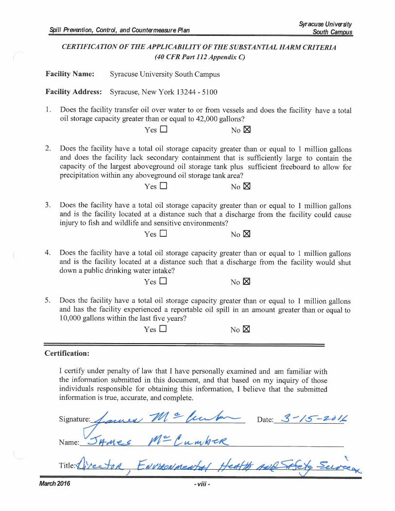
15. CERTIFICATE OF THE APPLICABILITY OF THE SUBSTANTIAL HARM CRITERIA
Regulations in 40 CFR Part 112 require certain larger facilities that may pose a substantial harm to the environment to prepare and submit a Facility Response Plan to the Regional Environmental Protection Agency Administrator. The total oil storage capacity for the Syracuse University South Campus is well below the thresholds for such facilities. Therefore, a Facility Response Plan is not required for this facility.
Appendix C to 40 CFR Part 112 requires certification for facilities that do not pose substantial harm to the environment. A Certificate of the Applicability of the Substantial Harm Criteria form is attached to Appendix F of this Plan to document that this facility is not required to produce such a response plan. In the event that the facility was further developed in the future such that these thresholds were exceeded, or should the rule be altered to incorporate smaller facilities, a Facility Response Plan may be required.

FIGURES
Figure 1 – Facility Plan

TA BLES
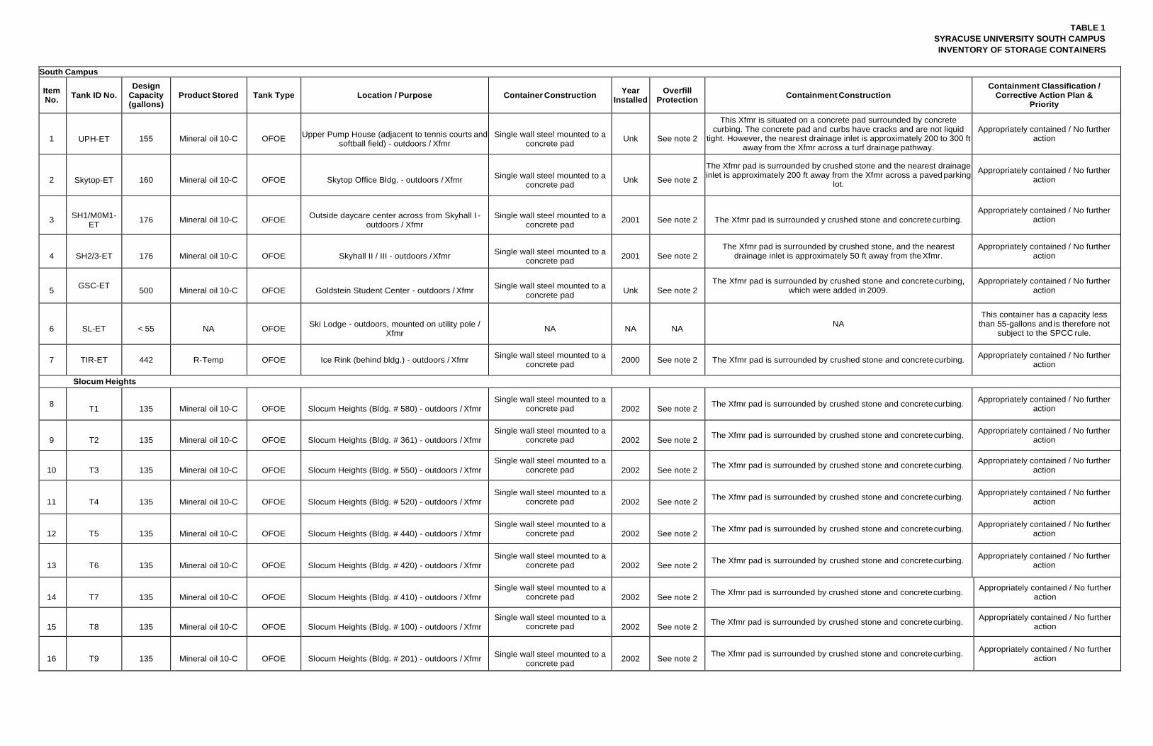
TABLE 1 SYRACUSE UNIVERSITY SOUTH CAMPUS INVENTORY OF STORAGE CONTAINERS
South Campus
Item No. Tank ID No.
Design Capacity (gallons)
Product Stored Tank Type Location / Purpose Container Construction Year Installed
Overfill Protection Containment Construction
Containment Classification / Corrective Action Plan &
Priority
1
UPH-ET
155
Mineral oil 10-C
OFOE
Upper Pump House (adjacent to tennis courts and
softball field) - outdoors / Xfmr
Single wall steel mounted to a
concrete pad
Unk
See note 2
This Xfmr is situated on a concrete pad surrounded by concrete curbing. The concrete pad and curbs have cracks and are not liquid
tight. However, the nearest drainage inlet is approximately 200 to 300 ft away from the Xfmr across a turf drainage pathway.
Appropriately contained / No further action
2
Skytop-ET
160
Mineral oil 10-C
OFOE
Skytop Office Bldg. - outdoors / Xfmr
Single wall steel mounted to a
concrete pad
Unk
See note 2
The Xfmr pad is surrounded by crushed stone and the nearest drainage inlet is approximately 200 ft away from the Xfmr across a paved parking
lot.
Appropriately contained / No further action
3
SH1/M0M1-
ET
176
Mineral oil 10-C
OFOE
Outside daycare center across from Skyhall I -
outdoors / Xfmr
Single wall steel mounted to a
concrete pad
2001
See note 2
The Xfmr pad is surrounded y crushed stone and concrete curbing.
Appropriately contained / No further action
4
SH2/3-ET
176
Mineral oil 10-C
OFOE
Skyhall II / III - outdoors / Xfmr
Single wall steel mounted to a
concrete pad
2001
See note 2
The Xfmr pad is surrounded by crushed stone, and the nearest drainage inlet is approximately 50 ft away from the Xfmr.
Appropriately contained / No further action
5 GSC-ET
500
Mineral oil 10-C
OFOE
Goldstein Student Center - outdoors / Xfmr
Single wall steel mounted to a
concrete pad
Unk
See note 2
The Xfmr pad is surrounded by crushed stone and concrete curbing, which were added in 2009.
Appropriately contained / No further action
6
SL-ET
< 55
NA
OFOE
Ski Lodge - outdoors, mounted on utility pole /
Xfmr
NA
NA
NA NA
This container has a capacity less than 55-gallons and is therefore not
subject to the SPCC rule.
7 TIR-ET 442 R-Temp OFOE Ice Rink (behind bldg.) - outdoors / Xfmr Single wall steel mounted to a concrete pad 2000 See note 2 The Xfmr pad is surrounded by crushed stone and concrete curbing. Appropriately contained / No further
action
Slocum Heights
8 T1
135
Mineral oil 10-C
OFOE
Slocum Heights (Bldg. # 580) - outdoors / Xfmr
Single wall steel mounted to a concrete pad
2002
See note 2 The Xfmr pad is surrounded by crushed stone and concrete curbing. Appropriately contained / No further
action
9
T2
135
Mineral oil 10-C
OFOE
Slocum Heights (Bldg. # 361) - outdoors / Xfmr
Single wall steel mounted to a concrete pad
2002
See note 2 The Xfmr pad is surrounded by crushed stone and concrete curbing. Appropriately contained / No further
action
10
T3
135
Mineral oil 10-C
OFOE
Slocum Heights (Bldg. # 550) - outdoors / Xfmr
Single wall steel mounted to a concrete pad
2002
See note 2 The Xfmr pad is surrounded by crushed stone and concrete curbing. Appropriately contained / No further
action
11
T4
135
Mineral oil 10-C
OFOE
Slocum Heights (Bldg. # 520) - outdoors / Xfmr
Single wall steel mounted to a concrete pad
2002
See note 2 The Xfmr pad is surrounded by crushed stone and concrete curbing. Appropriately contained / No further
action
12
T5
135
Mineral oil 10-C
OFOE
Slocum Heights (Bldg. # 440) - outdoors / Xfmr
Single wall steel mounted to a concrete pad
2002
See note 2 The Xfmr pad is surrounded by crushed stone and concrete curbing. Appropriately contained / No further
action
13
T6
135
Mineral oil 10-C
OFOE
Slocum Heights (Bldg. # 420) - outdoors / Xfmr
Single wall steel mounted to a concrete pad
2002
See note 2 The Xfmr pad is surrounded by crushed stone and concrete curbing. Appropriately contained / No further
action
14
T7
135
Mineral oil 10-C
OFOE
Slocum Heights (Bldg. # 410) - outdoors / Xfmr
Single wall steel mounted to a concrete pad
2002
See note 2 The Xfmr pad is surrounded by crushed stone and concrete curbing. Appropriately contained / No further
action
15
T8
135
Mineral oil 10-C
OFOE
Slocum Heights (Bldg. # 100) - outdoors / Xfmr
Single wall steel mounted to a concrete pad
2002
See note 2 The Xfmr pad is surrounded by crushed stone and concrete curbing. Appropriately contained / No further
action
16
T9
135
Mineral oil 10-C
OFOE
Slocum Heights (Bldg. # 201) - outdoors / Xfmr
Single wall steel mounted to a
concrete pad
2002
See note 2 The Xfmr pad is surrounded by crushed stone and concrete curbing. Appropriately contained / No further
action
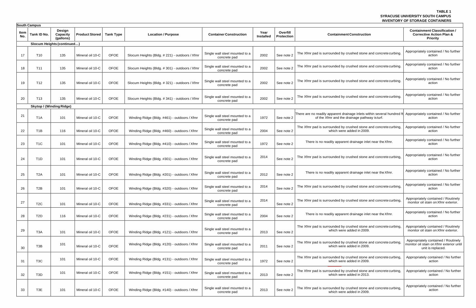
TABLE 1 SYRACUSE UNIVERSITY SOUTH CAMPUS INVENTORY OF STORAGE CONTAINERS
1972
1972
1972
South Campus
Item No. Tank ID No.
Design Capacity (gallons)
Product Stored Tank Type Location / Purpose Container Construction Year Installed
Overfill Protection Containment Construction
Containment Classification / Corrective Action Plan &
Priority
Slocum Heights (continued…)
17
T10
135
Mineral oil 10-C
OFOE
Slocum Heights (Bldg. # 221) - outdoors / Xfmr
Single wall steel mounted to a
concrete pad
2002
See note 2 The Xfmr pad is surrounded by crushed stone and concrete curbing. Appropriately contained / No further
action
18
T11
135
Mineral oil 10-C
OFOE
Slocum Heights (Bldg. # 301) - outdoors / Xfmr
Single wall steel mounted to a
concrete pad
2002
See note 2 The Xfmr pad is surrounded by crushed stone and concrete curbing. Appropriately contained / No further
action
19
T12
135
Mineral oil 10-C
OFOE
Slocum Heights (Bldg. # 321) - outdoors / Xfmr
Single wall steel mounted to a
concrete pad
2002
See note 2 The Xfmr pad is surrounded by crushed stone and concrete curbing. Appropriately contained / No further
action
20
T13
135
Mineral oil 10-C
OFOE
Slocum Heights (Bldg. # 341) - outdoors / Xfmr
Single wall steel mounted to a
concrete pad
2002
See note 2 The Xfmr pad is surrounded by crushed stone and concrete curbing. Appropriately contained / No further
action
Skytop I (Winding Ridge)
21 T1A
101
Mineral oil 10-C
OFOE
Winding Ridge (Bldg. #461) - outdoors / Xfmr
Single wall steel mounted to a
concrete pad
1972
See note 2
There are no readily apparent drainage inlets within several hundred ft of the Xfmr and the drainage pathway is turf.
Appropriately contained / No further action
22
T1B
116
Mineral oil 10-C
OFOE
Winding Ridge (Bldg. #460) - outdoors / Xfmr
Single wall steel mounted to a
concrete pad
2004
See note 2
The Xfmr pad is surrounded by crushed stone and concrete curbing, which were added in 2009.
Appropriately contained / No further action
23
T1C
101
Mineral oil 10-C
OFOE
Winding Ridge (Bldg. #410) - outdoors / Xfmr
Single wall steel mounted to a
concrete pad
1972
See note 2 There is no readily apparent drainage inlet near the Xfmr. Appropriately contained / No further
action
24
T1D
101
Mineral oil 10-C
OFOE
Winding Ridge (Bldg. #301) - outdoors / Xfmr
Single wall steel mounted to a
concrete pad 2014
See note 2 The Xfmr pad is surrounded by crushed stone and concrete curbing, Appropriately contained / No further action
25
T2A
101
Mineral oil 10-C
OFOE
Winding Ridge (Bldg. #201) - outdoors / Xfmr
Single wall steel mounted to a
concrete pad
2012
See note 2 There is no readily apparent drainage inlet near the Xfmr. Appropriately contained / No further
action
26
T2B
101
Mineral oil 10-C
OFOE
Winding Ridge (Bldg. #320) - outdoors / Xfmr
Single wall steel mounted to a
concrete pad 2014
See note 2 The Xfmr pad is surrounded by crushed stone and concrete curbing, Appropriately contained / No further action
27
T2C
101
Mineral oil 10-C
OFOE
Winding Ridge (Bldg. #331) - outdoors / Xfmr
Single wall steel mounted to a
concrete pad 2014
See note 2 The Xfmr pad is surrounded by crushed stone and concrete curbing, Appropriately contained / Routinely
monitor oil stain on Xfmr exterior.
28
T2D
116
Mineral oil 10-C
OFOE
Winding Ridge (Bldg. #231) - outdoors / Xfmr
Single wall steel mounted to a
concrete pad
2004
See note 2 There is no readily apparent drainage inlet near the Xfmr. Appropriately contained / No further
action
29
T3A
101
Mineral oil 10-C
OFOE
Winding Ridge (Bldg. #121) - outdoors / Xfmr
Single wall steel mounted to a
concrete pad
2013
See note 2
The Xfmr pad is surrounded by crushed stone and concrete curbing, which were added in 2009.
Appropriately contained / Routinely monitor oil stain on Xfmr exterior.
30
T3B 101
Mineral oil 10-C
OFOE Winding Ridge (Bldg. #120) - outdoors / Xfmr
Single wall steel mounted to a concrete pad
2011
See note 2
The Xfmr pad is surrounded by crushed stone and concrete curbing, which were added in 2009.
Appropriately contained / Routinely monitor oil stain on Xfmr exterior until
unit is replaced.
31
T3C 101 Mineral oil 10-C OFOE Winding Ridge (Bldg. #131) - outdoors / Xfmr
Single wall steel mounted to a
concrete pad
1972
See note 2
The Xfmr pad is surrounded by crushed stone and concrete curbing, which were added in 2009.
Appropriately contained / No further action
32
T3D 101 Mineral oil 10-C OFOE Winding Ridge (Bldg. #151) - outdoors / Xfmr
Single wall steel mounted to a
concrete pad
2013
See note 2
The Xfmr pad is surrounded by crushed stone and concrete curbing, which were added in 2013.
Appropriately contained / No further action
33
T3E
101
Mineral oil 10-C
OFOE
Winding Ridge (Bldg. #140) - outdoors / Xfmr
Single wall steel mounted to a
concrete pad
2013
See note 2
The Xfmr pad is surrounded by crushed stone and concrete curbing,
which were added in 2009.
Appropriately contained / No further action
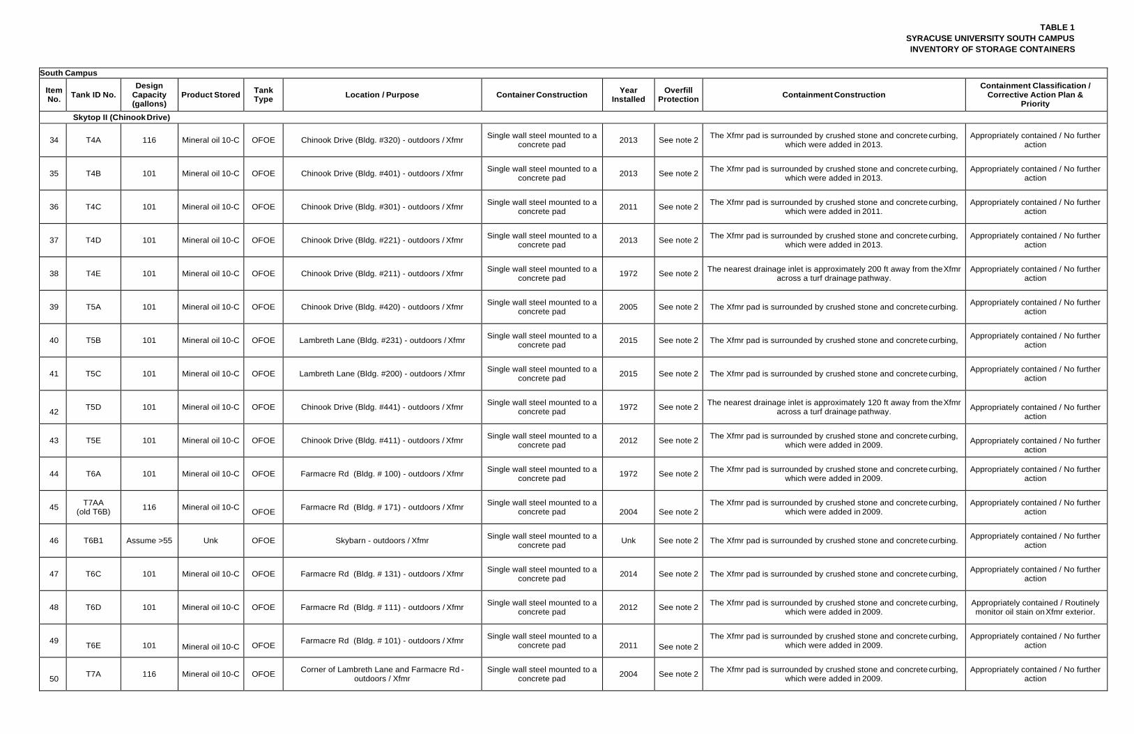
TABLE 1 SYRACUSE UNIVERSITY SOUTH CAMPUS INVENTORY OF STORAGE CONTAINERS
South Campus
Item No. Tank ID No.
Design Capacity (gallons)
Product Stored Tank Type Location / Purpose Container Construction Year
Installed Overfill
Protection Containment Construction Containment Classification /
Corrective Action Plan & Priority
Skytop II (Chinook Drive)
34 T4A 116 Mineral oil 10-C OFOE Chinook Drive (Bldg. #320) - outdoors / Xfmr Single wall steel mounted to a concrete pad 2013 See note 2 The Xfmr pad is surrounded by crushed stone and concrete curbing,
which were added in 2013. Appropriately contained / No further
action
35 T4B 101 Mineral oil 10-C OFOE Chinook Drive (Bldg. #401) - outdoors / Xfmr Single wall steel mounted to a concrete pad 2013 See note 2 The Xfmr pad is surrounded by crushed stone and concrete curbing,
which were added in 2013. Appropriately contained / No further
action
36 T4C 101 Mineral oil 10-C OFOE Chinook Drive (Bldg. #301) - outdoors / Xfmr Single wall steel mounted to a concrete pad 2011 See note 2 The Xfmr pad is surrounded by crushed stone and concrete curbing,
which were added in 2011. Appropriately contained / No further
action
37 T4D 101 Mineral oil 10-C OFOE Chinook Drive (Bldg. #221) - outdoors / Xfmr Single wall steel mounted to a concrete pad 2013 See note 2 The Xfmr pad is surrounded by crushed stone and concrete curbing,
which were added in 2013. Appropriately contained / No further
action
38 T4E 101 Mineral oil 10-C OFOE Chinook Drive (Bldg. #211) - outdoors / Xfmr Single wall steel mounted to a concrete pad 1972 See note 2 The nearest drainage inlet is approximately 200 ft away from the Xfmr
across a turf drainage pathway. Appropriately contained / No further
action
39 T5A 101 Mineral oil 10-C OFOE Chinook Drive (Bldg. #420) - outdoors / Xfmr Single wall steel mounted to a concrete pad 2005 See note 2 The Xfmr pad is surrounded by crushed stone and concrete curbing. Appropriately contained / No further
action
40 T5B 101 Mineral oil 10-C OFOE Lambreth Lane (Bldg. #231) - outdoors / Xfmr Single wall steel mounted to a concrete pad 2015 See note 2 The Xfmr pad is surrounded by crushed stone and concrete curbing, Appropriately contained / No further
action
41 T5C 101 Mineral oil 10-C OFOE Lambreth Lane (Bldg. #200) - outdoors / Xfmr Single wall steel mounted to a concrete pad 2015 See note 2 The Xfmr pad is surrounded by crushed stone and concrete curbing, Appropriately contained / No further
action
42 T5D 101 Mineral oil 10-C OFOE Chinook Drive (Bldg. #441) - outdoors / Xfmr Single wall steel mounted to a
concrete pad 1972 See note 2 The nearest drainage inlet is approximately 120 ft away from the Xfmr across a turf drainage pathway.
Appropriately contained / No further
action
43 T5E 101 Mineral oil 10-C OFOE Chinook Drive (Bldg. #411) - outdoors / Xfmr Single wall steel mounted to a concrete pad 2012 See note 2 The Xfmr pad is surrounded by crushed stone and concrete curbing,
which were added in 2009.
Appropriately contained / No further
action
44 T6A 101 Mineral oil 10-C OFOE Farmacre Rd (Bldg. # 100) - outdoors / Xfmr Single wall steel mounted to a concrete pad 1972 See note 2 The Xfmr pad is surrounded by crushed stone and concrete curbing,
which were added in 2009. Appropriately contained / No further
action
45 T7AA (old T6B) 116 Mineral oil 10-C
OFOE Farmacre Rd (Bldg. # 171) - outdoors / Xfmr Single wall steel mounted to a concrete pad
2004
See note 2
The Xfmr pad is surrounded by crushed stone and concrete curbing, which were added in 2009.
Appropriately contained / No further action
46 T6B1 Assume >55 Unk OFOE Skybarn - outdoors / Xfmr Single wall steel mounted to a concrete pad Unk See note 2 The Xfmr pad is surrounded by crushed stone and concrete curbing. Appropriately contained / No further
action
47 T6C 101 Mineral oil 10-C OFOE Farmacre Rd (Bldg. # 131) - outdoors / Xfmr Single wall steel mounted to a concrete pad 2014 See note 2 The Xfmr pad is surrounded by crushed stone and concrete curbing, Appropriately contained / No further
action
48 T6D 101 Mineral oil 10-C OFOE Farmacre Rd (Bldg. # 111) - outdoors / Xfmr Single wall steel mounted to a concrete pad 2012 See note 2 The Xfmr pad is surrounded by crushed stone and concrete curbing,
which were added in 2009. Appropriately contained / Routinely monitor oil stain on Xfmr exterior.
49 T6E
101
Mineral oil 10-C
OFOE Farmacre Rd (Bldg. # 101) - outdoors / Xfmr Single wall steel mounted to a
concrete pad
2011
See note 2 The Xfmr pad is surrounded by crushed stone and concrete curbing,
which were added in 2009. Appropriately contained / No further
action
50 T7A 116 Mineral oil 10-C OFOE Corner of Lambreth Lane and Farmacre Rd -
outdoors / Xfmr Single wall steel mounted to a
concrete pad 2004 See note 2 The Xfmr pad is surrounded by crushed stone and concrete curbing, which were added in 2009.
Appropriately contained / No further action
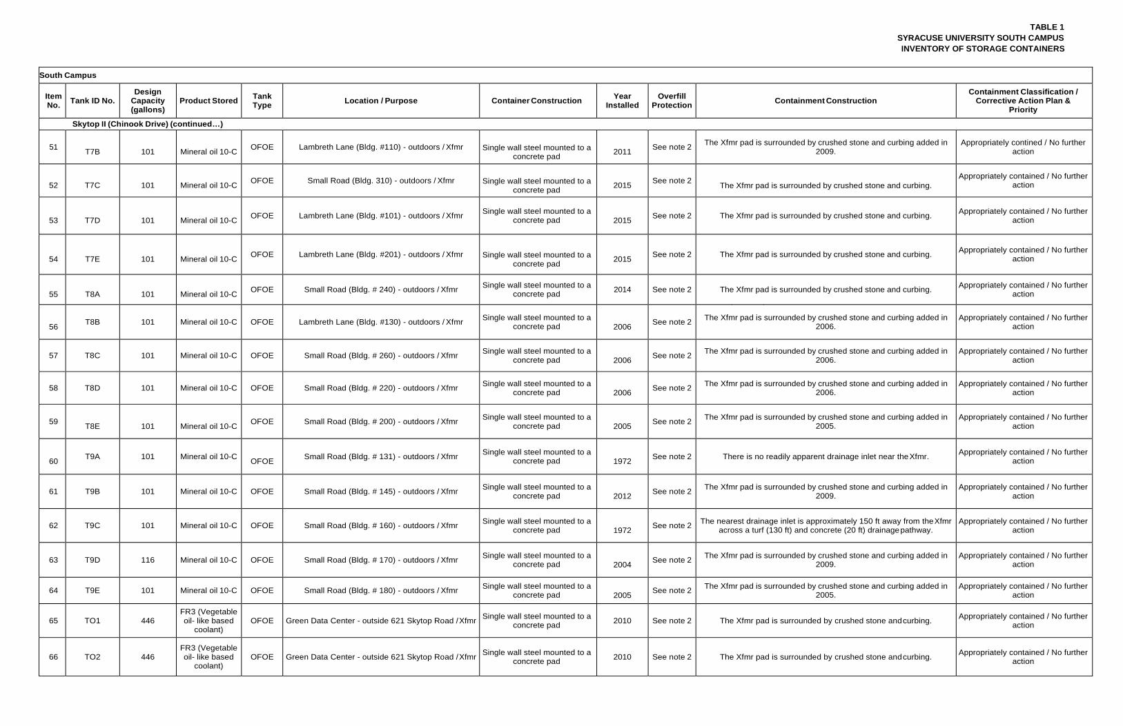
TABLE 1 SYRACUSE UNIVERSITY SOUTH CAMPUS INVENTORY OF STORAGE CONTAINERS
1972
South Campus
Item No. Tank ID No.
Design Capacity (gallons)
Product Stored Tank Type Location / Purpose Container Construction Year
Installed Overfill
Protection Containment Construction Containment Classification /
Corrective Action Plan & Priority
Skytop II (Chinook Drive) (continued…)
51 T7B
101
Mineral oil 10-C OFOE Lambreth Lane (Bldg. #110) - outdoors / Xfmr
Single wall steel mounted to a
concrete pad
2011 See note 2 The Xfmr pad is surrounded by crushed stone and curbing added in
2009. Appropriately contined / No further
action
52
T7C
101
Mineral oil 10-C OFOE Small Road (Bldg. 310) - outdoors / Xfmr
Single wall steel mounted to a
concrete pad
2015 See note 2
The Xfmr pad is surrounded by crushed stone and curbing. Appropriately contained / No further
action
53
T7D
101
Mineral oil 10-C OFOE Lambreth Lane (Bldg. #101) - outdoors / Xfmr Single wall steel mounted to a
concrete pad
2015 See note 2 The Xfmr pad is surrounded by crushed stone and curbing. Appropriately contained / No further action
54
T7E
101
Mineral oil 10-C OFOE Lambreth Lane (Bldg. #201) - outdoors / Xfmr
Single wall steel mounted to a
concrete pad
2015 See note 2 The Xfmr pad is surrounded by crushed stone and curbing. Appropriately contained / No further
action
55
T8A
101
Mineral oil 10-C OFOE Small Road (Bldg. # 240) - outdoors / Xfmr Single wall steel mounted to a
concrete pad 2014 See note 2 The Xfmr pad is surrounded by crushed stone and curbing. Appropriately contained / No further action
56 T8B 101 Mineral oil 10-C OFOE Lambreth Lane (Bldg. #130) - outdoors / Xfmr Single wall steel mounted to a
concrete pad
2006 See note 2 The Xfmr pad is surrounded by crushed stone and curbing added in 2006.
Appropriately contained / No further action
57 T8C 101 Mineral oil 10-C OFOE Small Road (Bldg. # 260) - outdoors / Xfmr Single wall steel mounted to a concrete pad
2006 See note 2 The Xfmr pad is surrounded by crushed stone and curbing added in
2006. Appropriately contained / No further
action
58 T8D 101 Mineral oil 10-C OFOE Small Road (Bldg. # 220) - outdoors / Xfmr Single wall steel mounted to a concrete pad
2006 See note 2 The Xfmr pad is surrounded by crushed stone and curbing added in
2006. Appropriately contained / No further
action
59 T8E
101
Mineral oil 10-C OFOE Small Road (Bldg. # 200) - outdoors / Xfmr Single wall steel mounted to a
concrete pad
2005 See note 2 The Xfmr pad is surrounded by crushed stone and curbing added in 2005.
Appropriately contained / No further action
60 T9A 101 Mineral oil 10-C
OFOE Small Road (Bldg. # 131) - outdoors / Xfmr Single wall steel mounted to a concrete pad
1972 See note 2 There is no readily apparent drainage inlet near the Xfmr. Appropriately contained / No further
action
61 T9B 101 Mineral oil 10-C OFOE Small Road (Bldg. # 145) - outdoors / Xfmr Single wall steel mounted to a concrete pad
2012 See note 2 The Xfmr pad is surrounded by crushed stone and curbing added in
2009. Appropriately contained / No further
action
62 T9C 101 Mineral oil 10-C OFOE Small Road (Bldg. # 160) - outdoors / Xfmr Single wall steel mounted to a concrete pad
1972 See note 2 The nearest drainage inlet is approximately 150 ft away from the Xfmr
across a turf (130 ft) and concrete (20 ft) drainage pathway. Appropriately contained / No further
action
63 T9D 116 Mineral oil 10-C OFOE Small Road (Bldg. # 170) - outdoors / Xfmr Single wall steel mounted to a concrete pad
2004 See note 2 The Xfmr pad is surrounded by crushed stone and curbing added in
2009. Appropriately contained / No further
action
64 T9E 101 Mineral oil 10-C OFOE Small Road (Bldg. # 180) - outdoors / Xfmr Single wall steel mounted to a concrete pad
2005 See note 2 The Xfmr pad is surrounded by crushed stone and curbing added in
2005. Appropriately contained / No further
action
65 TO1 446 FR3 (Vegetable oil- like based
coolant) OFOE Green Data Center - outside 621 Skytop Road / Xfmr Single wall steel mounted to a
concrete pad 2010 See note 2 The Xfmr pad is surrounded by crushed stone and curbing. Appropriately contained / No further action
66 TO2 446 FR3 (Vegetable oil- like based
coolant) OFOE Green Data Center - outside 621 Skytop Road / Xfmr Single wall steel mounted to a
concrete pad 2010 See note 2 The Xfmr pad is surrounded by crushed stone and curbing. Appropriately contained / No further action
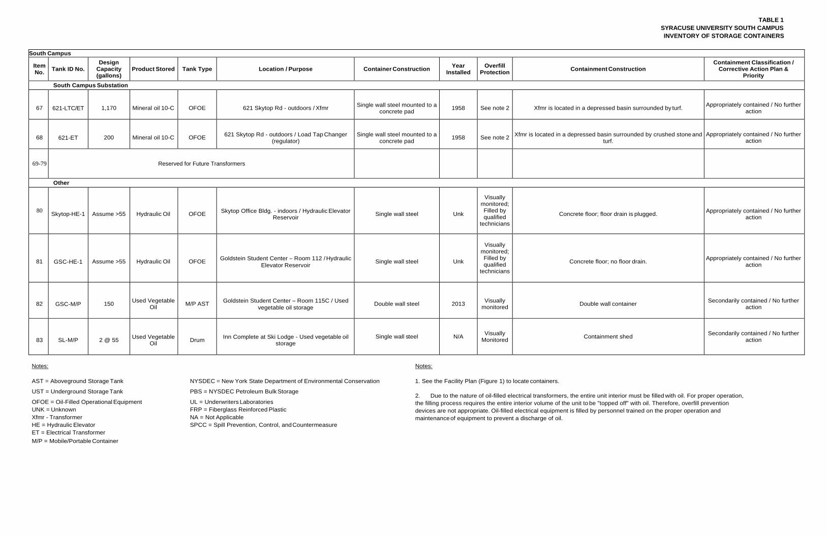
TABLE 1 SYRACUSE UNIVERSITY SOUTH CAMPUS INVENTORY OF STORAGE CONTAINERS
South Campus
Item No. Tank ID No.
Design Capacity (gallons)
Product Stored Tank Type Location / Purpose Container Construction Year Installed
Overfill Protection Containment Construction
Containment Classification / Corrective Action Plan &
Priority
South Campus Substation
67
621-LTC/ET
1,170
Mineral oil 10-C
OFOE
621 Skytop Rd - outdoors / Xfmr
Single wall steel mounted to a
concrete pad
1958
See note 2
Xfmr is located in a depressed basin surrounded by turf.
Appropriately contained / No further
action
68
621-ET
200
Mineral oil 10-C
OFOE
621 Skytop Rd - outdoors / Load Tap Changer
(regulator)
Single wall steel mounted to a
concrete pad
1958
See note 2
Xfmr is located in a depressed basin surrounded by crushed stone and
turf.
Appropriately contained / No further
action
69-79 Reserved for Future Transformers
Other
80 Skytop-HE-1
Assume >55
Hydraulic Oil
OFOE
Skytop Office Bldg. - indoors / Hydraulic Elevator
Reservoir
Single wall steel
Unk
Visually monitored; Filled by qualified
technicians
Concrete floor; floor drain is plugged.
Appropriately contained / No further
action
81
GSC-HE-1
Assume >55
Hydraulic Oil
OFOE
Goldstein Student Center – Room 112 / Hydraulic
Elevator Reservoir
Single wall steel
Unk
Visually monitored; Filled by qualified
technicians
Concrete floor; no floor drain.
Appropriately contained / No further
action
82
GSC-M/P
150
Used Vegetable
Oil
M/P AST
Goldstein Student Center – Room 115C / Used
vegetable oil storage
Double wall steel
2013
Visually
monitored
Double wall container
Secondarily contained / No further
action
83
SL-M/P
2 @ 55
Used Vegetable
Oil
Drum
Inn Complete at Ski Lodge - Used vegetable oil
storage Single wall steel N/A Visually
Monitored Containment shed Secondarily contained / No further action
Notes: Notes:
AST = Aboveground Storage Tank NYSDEC = New York State Department of Environmental Conservation 1. See the Facility Plan (Figure 1) to locate containers.
UST = Underground Storage Tank PBS = NYSDEC Petroleum Bulk Storage
OFOE = Oil-Filled Operational Equipment UL = Underwriters Laboratories UNK = Unknown FRP = Fiberglass Reinforced Plastic Xfmr - Transformer NA = Not Applicable HE = Hydraulic Elevator SPCC = Spill Prevention, Control, and Countermeasure ET = Electrical Transformer M/P = Mobile/Portable Container
2. Due to the nature of oil-filled electrical transformers, the entire unit interior must be filled with oil. For proper operation, the filling process requires the entire interior volume of the unit to be "topped off" with oil. Therefore, overfill prevention devices are not appropriate. Oil-filled electrical equipment is filled by personnel trained on the proper operation and maintenance of equipment to prevent a discharge of oil.
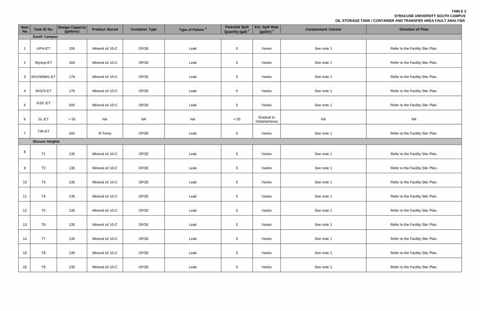
TABLE 2 SYRACUSE UNIVERSITY SOUTH CAMPUS
OIL STORAGE TANK / CONTAINER AND TRANSFER AREA FAULT ANALYSIS
Item No. Tank ID No. Design Capacity
(gallons) Product Stored Container Type Type of Failure 2
Potential Spill Quantity (gal) 2
Est. Spill Rate (gal/hr) 2
Containment Volume Direction of Flow
South Campus
1
UPH-ET
155
Mineral oil 10-C
OFOE
Leak
5
Varies
See note 1
Refer to the Facility Site Plan.
2
Skytop-ET
160
Mineral oil 10-C
OFOE
Leak
5
Varies
See note 1
Refer to the Facility Site Plan.
3
SH1/M0M1-ET
176
Mineral oil 10-C
OFOE
Leak
5
Varies
See note 1
Refer to the Facility Site Plan.
4
SH2/3-ET
176
Mineral oil 10-C
OFOE
Leak
5
Varies
See note 1
Refer to the Facility Site Plan.
5 GSC-ET
500
Mineral oil 10-C
OFOE
Leak
5
Varies
See note 1
Refer to the Facility Site Plan.
6
SL-ET
< 55
NA
NA
NA
< 55
Gradual to
Instantaneous
NA
NA
7 TIR-ET
442
R-Temp
OFOE
Leak
5
Varies
See note 1
Refer to the Facility Site Plan.
Slocum Heights
8 T1
135
Mineral oil 10-C
OFOE
Leak
5
Varies
See note 1
Refer to the Facility Site Plan.
9
T2
135
Mineral oil 10-C
OFOE
Leak
5
Varies
See note 1
Refer to the Facility Site Plan.
10
T3
135
Mineral oil 10-C
OFOE
Leak
5
Varies
See note 1
Refer to the Facility Site Plan.
11
T4
135
Mineral oil 10-C
OFOE
Leak
5
Varies
See note 1
Refer to the Facility Site Plan.
12
T5
135
Mineral oil 10-C
OFOE
Leak
5
Varies
See note 1
Refer to the Facility Site Plan.
13
T6
135
Mineral oil 10-C
OFOE
Leak
5
Varies
See note 1
Refer to the Facility Site Plan.
14
T7
135
Mineral oil 10-C
OFOE
Leak
5
Varies
See note 1
Refer to the Facility Site Plan.
15
T8
135
Mineral oil 10-C
OFOE
Leak
5
Varies
See note 1
Refer to the Facility Site Plan.
16
T9
135
Mineral oil 10-C
OFOE
Leak
5
Varies
See note 1
Refer to the Facility Site Plan.
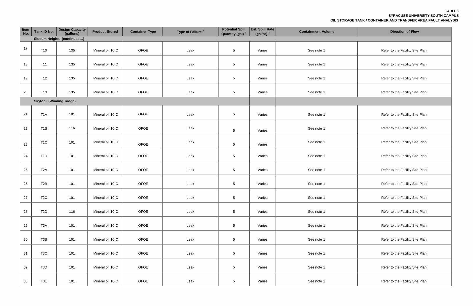
TABLE 2 SYRACUSE UNIVERSITY SOUTH CAMPUS
OIL STORAGE TANK / CONTAINER AND TRANSFER AREA FAULT ANALYSIS
Item No. Tank ID No. Design Capacity
(gallons) Product Stored Container Type Type of Failure 2
Potential Spill Quantity (gal) 2
Est. Spill Rate (gal/hr) 2
Containment Volume Direction of Flow
Slocum Heights (continued…)
17 T10
135
Mineral oil 10-C
OFOE
Leak
5
Varies
See note 1
Refer to the Facility Site Plan.
18
T11
135
Mineral oil 10-C
OFOE
Leak
5
Varies
See note 1
Refer to the Facility Site Plan.
19
T12
135
Mineral oil 10-C
OFOE
Leak
5
Varies
See note 1
Refer to the Facility Site Plan.
20
T13
135
Mineral oil 10-C
OFOE
Leak
5
Varies
See note 1
Refer to the Facility Site Plan.
Skytop I (Winding Ridge)
21
T1A
101
Mineral oil 10-C
OFOE
Leak
5
Varies
See note 1
Refer to the Facility Site Plan.
22
T1B
116
Mineral oil 10-C
OFOE
Leak
5
Varies
See note 1
Refer to the Facility Site Plan.
23
T1C
101
Mineral oil 10-C
OFOE
Leak
5
Varies
See note 1
Refer to the Facility Site Plan.
24
T1D
101
Mineral oil 10-C
OFOE
Leak
5
Varies
See note 1
Refer to the Facility Site Plan.
25
T2A
101
Mineral oil 10-C
OFOE
Leak
5
Varies
See note 1
Refer to the Facility Site Plan.
26
T2B
101
Mineral oil 10-C
OFOE
Leak
5
Varies
See note 1
Refer to the Facility Site Plan.
27
T2C
101
Mineral oil 10-C
OFOE
Leak
5
Varies
See note 1
Refer to the Facility Site Plan.
28
T2D
116
Mineral oil 10-C
OFOE
Leak
5
Varies
See note 1
Refer to the Facility Site Plan.
29
T3A
101
Mineral oil 10-C
OFOE
Leak
5
Varies
See note 1
Refer to the Facility Site Plan.
30
T3B
101
Mineral oil 10-C
OFOE
Leak
5
Varies
See note 1
Refer to the Facility Site Plan.
31
T3C
101
Mineral oil 10-C
OFOE
Leak
5
Varies
See note 1
Refer to the Facility Site Plan.
32
T3D
101
Mineral oil 10-C
OFOE
Leak
5
Varies
See note 1
Refer to the Facility Site Plan.
33
T3E
101
Mineral oil 10-C
OFOE
Leak
5
Varies
See note 1
Refer to the Facility Site Plan.
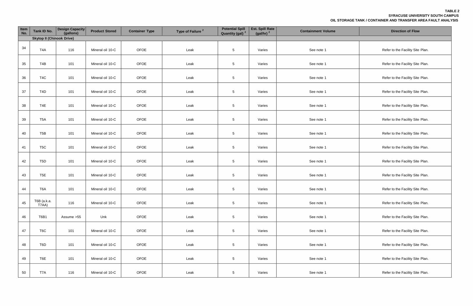
TABLE 2 SYRACUSE UNIVERSITY SOUTH CAMPUS
OIL STORAGE TANK / CONTAINER AND TRANSFER AREA FAULT ANALYSIS
Item No. Tank ID No. Design Capacity
(gallons) Product Stored Container Type Type of Failure 2
Potential Spill Quantity (gal) 2
Est. Spill Rate (gal/hr) 2
Containment Volume Direction of Flow
Skytop II (Chinook Drive)
34 T4A
116
Mineral oil 10-C
OFOE
Leak
5
Varies
See note 1
Refer to the Facility Site Plan.
35
T4B
101
Mineral oil 10-C
OFOE
Leak
5
Varies
See note 1
Refer to the Facility Site Plan.
36
T4C
101
Mineral oil 10-C
OFOE
Leak
5
Varies
See note 1
Refer to the Facility Site Plan.
37
T4D
101
Mineral oil 10-C
OFOE
Leak
5
Varies
See note 1
Refer to the Facility Site Plan.
38
T4E
101
Mineral oil 10-C
OFOE
Leak
5
Varies
See note 1
Refer to the Facility Site Plan.
39
T5A
101
Mineral oil 10-C
OFOE
Leak
5
Varies
See note 1
Refer to the Facility Site Plan.
40
T5B
101
Mineral oil 10-C
OFOE
Leak
5
Varies
See note 1
Refer to the Facility Site Plan.
41
T5C
101
Mineral oil 10-C
OFOE
Leak
5
Varies
See note 1
Refer to the Facility Site Plan.
42
T5D
101
Mineral oil 10-C
OFOE
Leak
5
Varies
See note 1
Refer to the Facility Site Plan.
43
T5E
101
Mineral oil 10-C
OFOE
Leak
5
Varies
See note 1
Refer to the Facility Site Plan.
44
T6A
101
Mineral oil 10-C
OFOE
Leak
5
Varies
See note 1
Refer to the Facility Site Plan.
45
T6B (a.k.a.
T7AA)
116
Mineral oil 10-C
OFOE
Leak
5
Varies
See note 1
Refer to the Facility Site Plan.
46
T6B1
Assume >55
Unk
OFOE
Leak
5
Varies
See note 1
Refer to the Facility Site Plan.
47
T6C
101
Mineral oil 10-C
OFOE
Leak
5
Varies
See note 1
Refer to the Facility Site Plan.
48
T6D
101
Mineral oil 10-C
OFOE
Leak
5
Varies
See note 1
Refer to the Facility Site Plan.
49
T6E
101
Mineral oil 10-C
OFOE
Leak
5
Varies
See note 1
Refer to the Facility Site Plan.
50
T7A
116
Mineral oil 10-C
OFOE
Leak
5
Varies
See note 1
Refer to the Facility Site Plan.
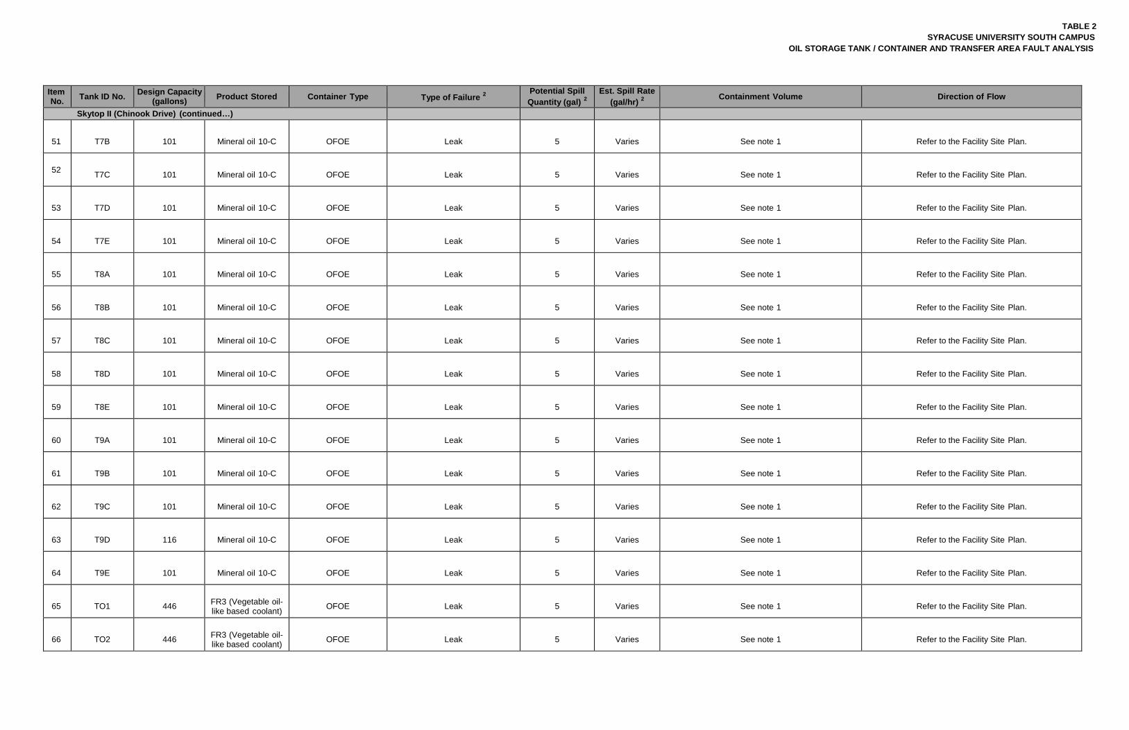
TABLE 2 SYRACUSE UNIVERSITY SOUTH CAMPUS
OIL STORAGE TANK / CONTAINER AND TRANSFER AREA FAULT ANALYSIS
Item No. Tank ID No. Design Capacity
(gallons) Product Stored Container Type Type of Failure 2
Potential Spill Quantity (gal) 2
Est. Spill Rate (gal/hr) 2
Containment Volume Direction of Flow
Skytop II (Chinook Drive) (continued…)
51
T7B
101
Mineral oil 10-C
OFOE
Leak
5
Varies
See note 1
Refer to the Facility Site Plan.
52 T7C
101
Mineral oil 10-C
OFOE
Leak
5
Varies
See note 1
Refer to the Facility Site Plan.
53
T7D
101
Mineral oil 10-C
OFOE
Leak
5
Varies
See note 1
Refer to the Facility Site Plan.
54
T7E
101
Mineral oil 10-C
OFOE
Leak
5
Varies
See note 1
Refer to the Facility Site Plan.
55
T8A
101
Mineral oil 10-C
OFOE
Leak
5
Varies
See note 1
Refer to the Facility Site Plan.
56
T8B
101
Mineral oil 10-C
OFOE
Leak
5
Varies
See note 1
Refer to the Facility Site Plan.
57
T8C
101
Mineral oil 10-C
OFOE
Leak
5
Varies
See note 1
Refer to the Facility Site Plan.
58
T8D
101
Mineral oil 10-C
OFOE
Leak
5
Varies
See note 1
Refer to the Facility Site Plan.
59
T8E
101
Mineral oil 10-C
OFOE
Leak
5
Varies
See note 1
Refer to the Facility Site Plan.
60
T9A
101
Mineral oil 10-C
OFOE
Leak
5
Varies
See note 1
Refer to the Facility Site Plan.
61
T9B
101
Mineral oil 10-C
OFOE
Leak
5
Varies
See note 1
Refer to the Facility Site Plan.
62
T9C
101
Mineral oil 10-C
OFOE
Leak
5
Varies
See note 1
Refer to the Facility Site Plan.
63
T9D
116
Mineral oil 10-C
OFOE
Leak
5
Varies
See note 1
Refer to the Facility Site Plan.
64
T9E
101
Mineral oil 10-C
OFOE
Leak
5
Varies
See note 1
Refer to the Facility Site Plan.
65
TO1
446
FR3 (Vegetable oil- like based coolant)
OFOE
Leak
5
Varies
See note 1
Refer to the Facility Site Plan.
66
TO2
446
FR3 (Vegetable oil- like based coolant)
OFOE
Leak
5
Varies
See note 1
Refer to the Facility Site Plan.
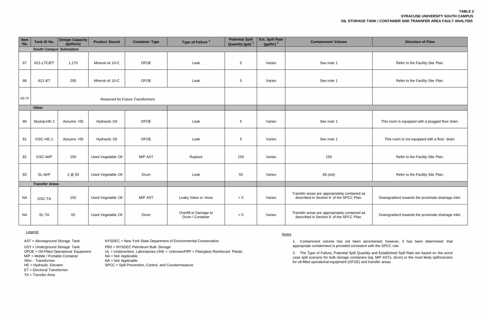
TABLE 2 SYRACUSE UNIVERSITY SOUTH CAMPUS
OIL STORAGE TANK / CONTAINER AND TRANSFER AREA FAULT ANALYSIS
Item No. Tank ID No. Design Capacity
(gallons) Product Stored Container Type Type of Failure 2
Potential Spill Quantity (gal) 2
Est. Spill Rate (gal/hr) 2
Containment Volume Direction of Flow
South Campus Substation
67
621-LTC/ET
1,170
Mineral oil 10-C
OFOE
Leak
5
Varies
See note 1
Refer to the Facility Site Plan.
68
621-ET
200
Mineral oil 10-C
OFOE
Leak
5
Varies
See note 1
Refer to the Facility Site Plan.
69-70
Reserved for Future Transformers
Other
80
Skytop-HE-1
Assume >55
Hydraulic Oil
OFOE
Leak
5
Varies
See note 1
This room is equipped with a plugged floor drain.
81
GSC-HE-1
Assume >55
Hydraulic Oil
OFOE
Leak
5
Varies
See note 1
This room is not equipped with a floor drain.
82
GSC-M/P
150
Used Vegetable Oil
M/P AST
Rupture
150
Varies
150
Refer to the Facility Site Plan.
83
SL-M/P
2 @ 55
Used Vegetable Oil
Drum
Leak
55
Varies
66 (est)
Refer to the Facility Site Plan.
Transfer Areas
NA
GSC-TA
150
Used Vegetable Oil
M/P AST
Leaky Valve or Hose
< 5
Varies Transfer areas are appropriately contained as
described in Section 8 of the SPCC Plan.
Downgradient towards the proximate drainage inlet.
NA SL-TA 55 Used Vegetable Oil Drum Overfill or Damage to Drum / Container < 5 Varies Transfer areas are appropriately contained as
described in Section 8 of the SPCC Plan. Downgradient towards the proximate drainage inlet.
Legend:
AST = Aboveground Storage Tank NYSDEC = New York State Department of Environmental Conservation
UST = Underground Storage Tank PBS = NYSDEC Petroleum Bulk Storage OFOE = Oil-Filled Operational Equipment UL = Underwriters Laboratories UNK = Unknown FRP = Fiberglass Reinforced Plastic M/P = Mobile / Portable Container NA = Not Applicable Xfmr - Transformer NA = Not Applicable HE = Hydraulic Elevator SPCC = Spill Prevention, Control, and Countermeasure ET = Electrical Transformer TA = Transfer Area
Notes
1. Containment volume has not been ascertained; however, it has been determined that appropriate containment is provided consistent with the SPCC rule.
2. The Type of Failure, Potential Spill Quantity and Established Spill Rate are based on the worst case spill scenario for bulk storage containers (eg .M/P ASTs, drum) or the most likely spill scenario for oil-filled operational equipment (OFOE) and transfer areas.
APPEN DIX A
40 CFR Part 112
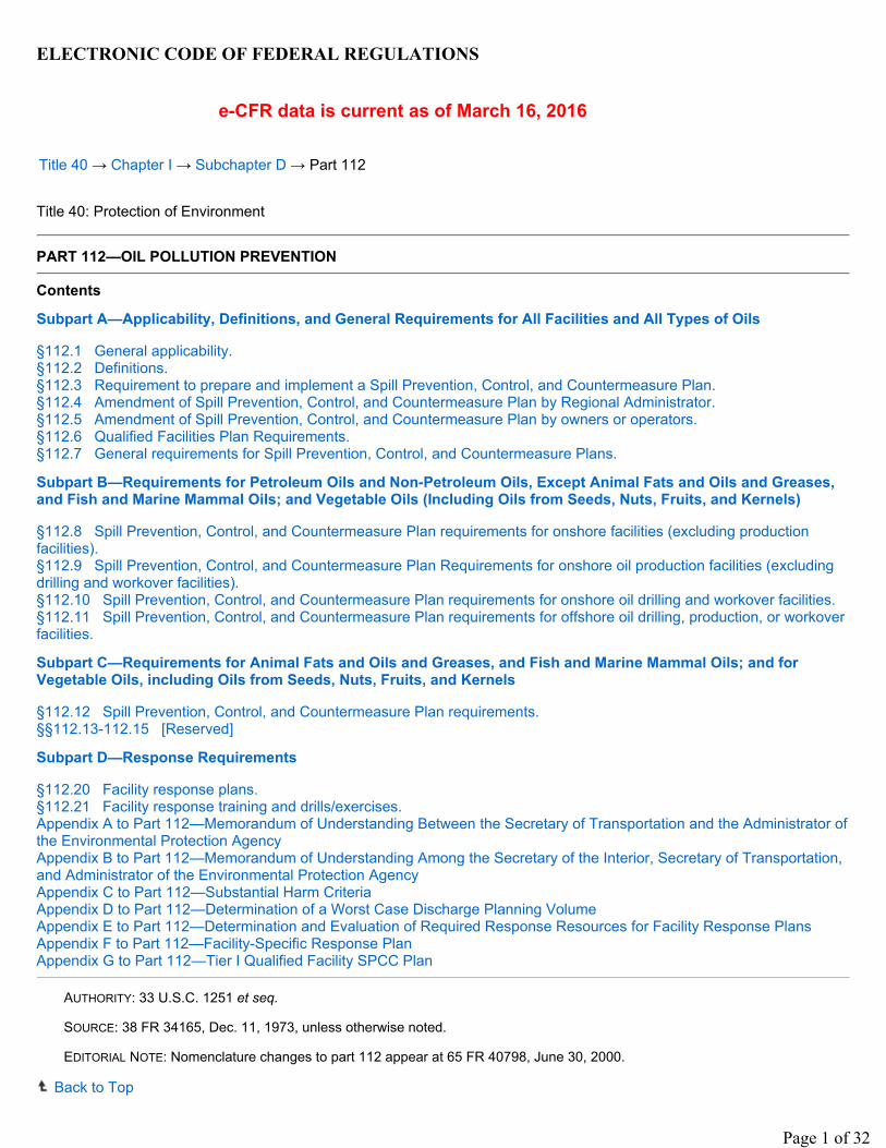
ELECTRONIC CODE OF FEDERAL REGULATIONS
e-CFR data is current as of March 16, 2016
Title 40 → Chapter I → Subchapter D → Part 112
Title 40: Protection of Environment
PART 112—OIL POLLUTION PREVENTION
Contents
Subpart A—Applicability, Definitions, and General Requirements for All Facilities and All Types of Oils
§112.1 General applicability.§112.2 Definitions.§112.3 Requirement to prepare and implement a Spill Prevention, Control, and Countermeasure Plan.§112.4 Amendment of Spill Prevention, Control, and Countermeasure Plan by Regional Administrator.§112.5 Amendment of Spill Prevention, Control, and Countermeasure Plan by owners or operators.§112.6 Qualified Facilities Plan Requirements.§112.7 General requirements for Spill Prevention, Control, and Countermeasure Plans.
Subpart B—Requirements for Petroleum Oils and Non-Petroleum Oils, Except Animal Fats and Oils and Greases, and Fish and Marine Mammal Oils; and Vegetable Oils (Including Oils from Seeds, Nuts, Fruits, and Kernels)
§112.8 Spill Prevention, Control, and Countermeasure Plan requirements for onshore facilities (excluding production facilities).§112.9 Spill Prevention, Control, and Countermeasure Plan Requirements for onshore oil production facilities (excluding drilling and workover facilities).§112.10 Spill Prevention, Control, and Countermeasure Plan requirements for onshore oil drilling and workover facilities.§112.11 Spill Prevention, Control, and Countermeasure Plan requirements for offshore oil drilling, production, or workover facilities.
Subpart C—Requirements for Animal Fats and Oils and Greases, and Fish and Marine Mammal Oils; and for Vegetable Oils, including Oils from Seeds, Nuts, Fruits, and Kernels
§112.12 Spill Prevention, Control, and Countermeasure Plan requirements.§§112.13-112.15 [Reserved]
Subpart D—Response Requirements
§112.20 Facility response plans.§112.21 Facility response training and drills/exercises.Appendix A to Part 112—Memorandum of Understanding Between the Secretary of Transportation and the Administrator of the Environmental Protection AgencyAppendix B to Part 112—Memorandum of Understanding Among the Secretary of the Interior, Secretary of Transportation, and Administrator of the Environmental Protection AgencyAppendix C to Part 112—Substantial Harm CriteriaAppendix D to Part 112—Determination of a Worst Case Discharge Planning VolumeAppendix E to Part 112—Determination and Evaluation of Required Response Resources for Facility Response PlansAppendix F to Part 112—Facility-Specific Response PlanAppendix G to Part 112—Tier I Qualified Facility SPCC Plan
AUTHORITY: 33 U.S.C. 1251 et seq.
SOURCE: 38 FR 34165, Dec. 11, 1973, unless otherwise noted.
EDITORIAL NOTE: Nomenclature changes to part 112 appear at 65 FR 40798, June 30, 2000.
Back to Top
Page 1 of 32
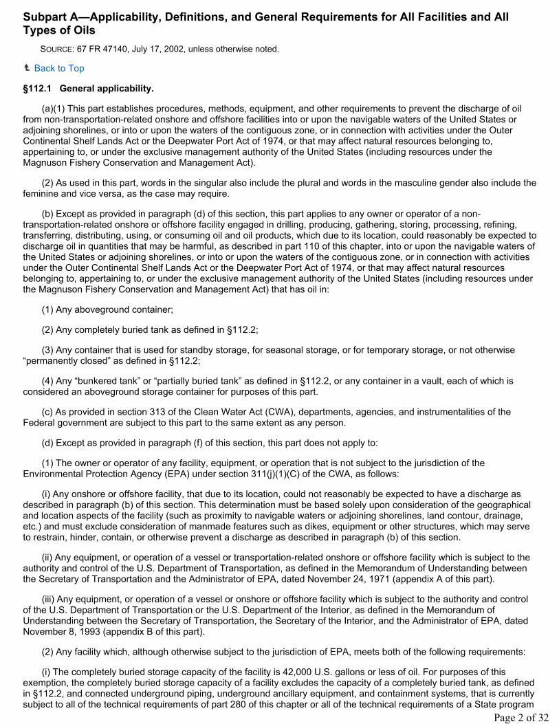
Subpart A—Applicability, Definitions, and General Requirements for All Facilities and All Types of Oils
SOURCE: 67 FR 47140, July 17, 2002, unless otherwise noted.
Back to Top
§112.1 General applicability.
(a)(1) This part establishes procedures, methods, equipment, and other requirements to prevent the discharge of oil from non-transportation-related onshore and offshore facilities into or upon the navigable waters of the United States or adjoining shorelines, or into or upon the waters of the contiguous zone, or in connection with activities under the Outer Continental Shelf Lands Act or the Deepwater Port Act of 1974, or that may affect natural resources belonging to, appertaining to, or under the exclusive management authority of the United States (including resources under the Magnuson Fishery Conservation and Management Act).
(2) As used in this part, words in the singular also include the plural and words in the masculine gender also include the feminine and vice versa, as the case may require.
(b) Except as provided in paragraph (d) of this section, this part applies to any owner or operator of a non-transportation-related onshore or offshore facility engaged in drilling, producing, gathering, storing, processing, refining, transferring, distributing, using, or consuming oil and oil products, which due to its location, could reasonably be expected to discharge oil in quantities that may be harmful, as described in part 110 of this chapter, into or upon the navigable waters of the United States or adjoining shorelines, or into or upon the waters of the contiguous zone, or in connection with activities under the Outer Continental Shelf Lands Act or the Deepwater Port Act of 1974, or that may affect natural resources belonging to, appertaining to, or under the exclusive management authority of the United States (including resources under the Magnuson Fishery Conservation and Management Act) that has oil in:
(1) Any aboveground container;
(2) Any completely buried tank as defined in §112.2;
(3) Any container that is used for standby storage, for seasonal storage, or for temporary storage, or not otherwise “permanently closed” as defined in §112.2;
(4) Any “bunkered tank” or “partially buried tank” as defined in §112.2, or any container in a vault, each of which is considered an aboveground storage container for purposes of this part.
(c) As provided in section 313 of the Clean Water Act (CWA), departments, agencies, and instrumentalities of the Federal government are subject to this part to the same extent as any person.
(d) Except as provided in paragraph (f) of this section, this part does not apply to:
(1) The owner or operator of any facility, equipment, or operation that is not subject to the jurisdiction of the Environmental Protection Agency (EPA) under section 311(j)(1)(C) of the CWA, as follows:
(i) Any onshore or offshore facility, that due to its location, could not reasonably be expected to have a discharge as described in paragraph (b) of this section. This determination must be based solely upon consideration of the geographical and location aspects of the facility (such as proximity to navigable waters or adjoining shorelines, land contour, drainage, etc.) and must exclude consideration of manmade features such as dikes, equipment or other structures, which may serve to restrain, hinder, contain, or otherwise prevent a discharge as described in paragraph (b) of this section.
(ii) Any equipment, or operation of a vessel or transportation-related onshore or offshore facility which is subject to the authority and control of the U.S. Department of Transportation, as defined in the Memorandum of Understanding between the Secretary of Transportation and the Administrator of EPA, dated November 24, 1971 (appendix A of this part).
(iii) Any equipment, or operation of a vessel or onshore or offshore facility which is subject to the authority and control of the U.S. Department of Transportation or the U.S. Department of the Interior, as defined in the Memorandum of Understanding between the Secretary of Transportation, the Secretary of the Interior, and the Administrator of EPA, dated November 8, 1993 (appendix B of this part).
(2) Any facility which, although otherwise subject to the jurisdiction of EPA, meets both of the following requirements:
(i) The completely buried storage capacity of the facility is 42,000 U.S. gallons or less of oil. For purposes of this exemption, the completely buried storage capacity of a facility excludes the capacity of a completely buried tank, as defined in §112.2, and connected underground piping, underground ancillary equipment, and containment systems, that is currently subject to all of the technical requirements of part 280 of this chapter or all of the technical requirements of a State program
Page 2 of 32
approved under part 281 of this chapter, or the capacity of any underground oil storage tanks deferred under 40 CFR part 280 that supply emergency diesel generators at a nuclear power generation facility licensed by the Nuclear Regulatory Commission and subject to any Nuclear Regulatory Commission provision regarding design and quality criteria, including, but not limited to, 10 CFR part 50. The completely buried storage capacity of a facility also excludes the capacity of a container that is “permanently closed,” as defined in §112.2 and the capacity of intra-facility gathering lines subject to the regulatory requirements of 49 CFR part 192 or 195.
(ii) The aggregate aboveground storage capacity of the facility is 1,320 U.S. gallons or less of oil. For the purposes of this exemption, only containers with a capacity of 55 U.S. gallons or greater are counted. The aggregate aboveground storage capacity of a facility excludes:
(A) The capacity of a container that is “permanently closed” as defined in §112.2;
(B) The capacity of a “motive power container” as defined in §112.2;
(C) The capacity of hot-mix asphalt or any hot-mix asphalt container;
(D) The capacity of a container for heating oil used solely at a single-family residence;
(E) The capacity of pesticide application equipment and related mix containers.
(F) The capacity of any milk and milk product container and associated piping and appurtenances.
(3) Any offshore oil drilling, production, or workover facility that is subject to the notices and regulations of the Minerals Management Service, as specified in the Memorandum of Understanding between the Secretary of Transportation, the Secretary of the Interior, and the Administrator of EPA, dated November 8, 1993 (appendix B of this part).
(4) Any completely buried storage tank, as defined in §112.2, and connected underground piping, underground ancillary equipment, and containment systems, at any facility, that is subject to all of the technical requirements of part 280 of this chapter or a State program approved under part 281 of this chapter, or any underground oil storage tanks including below-grade vaulted tanks, deferred under 40 CFR part 280, as originally promulgated, that supply emergency diesel generators at a nuclear power generation facility licensed by the Nuclear Regulatory Commission, provided that such a tank is subject to any Nuclear Regulatory Commission provision regarding design and quality criteria, including, but not limited to, 10 CFR part 50. Such emergency generator tanks must be marked on the facility diagram as provided in §112.7(a)(3), if the facility is otherwise subject to this part.
(5) Any container with a storage capacity of less than 55 gallons of oil.
(6) Any facility or part thereof used exclusively for wastewater treatment and not used to satisfy any requirement of this part. The production, recovery, or recycling of oil is not wastewater treatment for purposes of this paragraph.
(7) Any “motive power container,” as defined in §112.2. The transfer of fuel or other oil into a motive power container at an otherwise regulated facility is not eligible for this exemption.
(8) Hot-mix asphalt, or any hot-mix asphalt container.
(9) Any container for heating oil used solely at a single-family residence.
(10) Any pesticide application equipment or related mix containers.
(11) Intra-facility gathering lines subject to the regulatory requirements of 49 CFR part 192 or 195, except that such a line's location must be identified and marked as “exempt” on the facility diagram as provided in §112.7(a)(3), if the facility is otherwise subject to this part.
(12) Any milk and milk product container and associated piping and appurtenances.
(e) This part establishes requirements for the preparation and implementation of Spill Prevention, Control, and Countermeasure (SPCC) Plans. SPCC Plans are designed to complement existing laws, regulations, rules, standards, policies, and procedures pertaining to safety standards, fire prevention, and pollution prevention rules. The purpose of an SPCC Plan is to form a comprehensive Federal/State spill prevention program that minimizes the potential for discharges. The SPCC Plan must address all relevant spill prevention, control, and countermeasures necessary at the specific facility. Compliance with this part does not in any way relieve the owner or operator of an onshore or an offshore facility from compliance with other Federal, State, or local laws.
(f) Notwithstanding paragraph (d) of this section, the Regional Administrator may require that the owner or operator of any facility subject to the jurisdiction of EPA under section 311(j) of the CWA prepare and implement an SPCC Plan, or any applicable part, to carry out the purposes of the CWA.
Page 3 of 32
(1) Following a preliminary determination, the Regional Administrator must provide a written notice to the owner or operator stating the reasons why he must prepare an SPCC Plan, or applicable part. The Regional Administrator must send such notice to the owner or operator by certified mail or by personal delivery. If the owner or operator is a corporation, the Regional Administrator must also mail a copy of such notice to the registered agent, if any and if known, of the corporation in the State where the facility is located.
(2) Within 30 days of receipt of such written notice, the owner or operator may provide information and data and may consult with the Agency about the need to prepare an SPCC Plan, or applicable part.
(3) Within 30 days following the time under paragraph (b)(2) of this section within which the owner or operator may provide information and data and consult with the Agency about the need to prepare an SPCC Plan, or applicable part, the Regional Administrator must make a final determination regarding whether the owner or operator is required to prepare and implement an SPCC Plan, or applicable part. The Regional Administrator must send the final determination to the owner or operator by certified mail or by personal delivery. If the owner or operator is a corporation, the Regional Administrator must also mail a copy of the final determination to the registered agent, if any and if known, of the corporation in the State where the facility is located.
(4) If the Regional Administrator makes a final determination that an SPCC Plan, or applicable part, is necessary, the owner or operator must prepare the Plan, or applicable part, within six months of that final determination and implement the Plan, or applicable part, as soon as possible, but not later than one year after the Regional Administrator has made a final determination.
(5) The owner or operator may appeal a final determination made by the Regional Administrator requiring preparation and implementation of an SPCC Plan, or applicable part, under this paragraph. The owner or operator must make the appeal to the Administrator of EPA within 30 days of receipt of the final determination under paragraph (b)(3) of this section from the Regional Administrator requiring preparation and/or implementation of an SPCC Plan, or applicable part. The owner or operator must send a complete copy of the appeal to the Regional Administrator at the time he makes the appeal to the Administrator. The appeal must contain a clear and concise statement of the issues and points of fact in the case. In the appeal, the owner or operator may also provide additional information. The additional information may be from any person. The Administrator may request additional information from the owner or operator. The Administrator must render a decision within 60 days of receiving the appeal or additional information submitted by the owner or operator and must serve the owner or operator with the decision made in the appeal in the manner described in paragraph (f)(1) of this section.
[67 FR 47140, July 17, 2002, as amended at 71 FR 77290, Dec. 26, 2006; 73 FR 74300, Dec. 5, 2008; 74 FR 58809, Nov. 13, 2009; 76 FR 21660, Apr. 18, 2011]
Back to Top
§112.2 Definitions.
For the purposes of this part:
Adverse weather means weather conditions that make it difficult for response equipment and personnel to clean up or remove spilled oil, and that must be considered when identifying response systems and equipment in a response plan for the applicable operating environment. Factors to consider include significant wave height as specified in appendix E to this part (as appropriate), ice conditions, temperatures, weather-related visibility, and currents within the area in which the systems or equipment is intended to function.
Alteration means any work on a container involving cutting, burning, welding, or heating operations that changes the physical dimensions or configuration of the container.
Animal fat means a non-petroleum oil, fat, or grease of animal, fish, or marine mammal origin.
Breakout tank means a container used to relieve surges in an oil pipeline system or to receive and store oil transported by a pipeline for reinjection and continued transportation by pipeline.
Bulk storage container means any container used to store oil. These containers are used for purposes including, but not limited to, the storage of oil prior to use, while being used, or prior to further distribution in commerce. Oil-filled electrical, operating, or manufacturing equipment is not a bulk storage container.
Bunkered tank means a container constructed or placed in the ground by cutting the earth and re-covering the container in a manner that breaks the surrounding natural grade, or that lies above grade, and is covered with earth, sand, gravel, asphalt, or other material. A bunkered tank is considered an aboveground storage container for purposes of this part.
Page 4 of 32
Completely buried tank means any container completely below grade and covered with earth, sand, gravel, asphalt, or other material. Containers in vaults, bunkered tanks, or partially buried tanks are considered aboveground storage containers for purposes of this part.
Complex means a facility possessing a combination of transportation-related and non-transportation-related components that is subject to the jurisdiction of more than one Federal agency under section 311(j) of the CWA.
Contiguous zone means the zone established by the United States under Article 24 of the Convention of the Territorial Sea and Contiguous Zone, that is contiguous to the territorial sea and that extends nine miles seaward from the outer limit of the territorial area.
Contract or other approved means means:
(1) A written contractual agreement with an oil spill removal organization that identifies and ensures the availability of the necessary personnel and equipment within appropriate response times; and/or
(2) A written certification by the owner or operator that the necessary personnel and equipment resources, owned or operated by the facility owner or operator, are available to respond to a discharge within appropriate response times; and/or
(3) Active membership in a local or regional oil spill removal organization that has identified and ensures adequate access through such membership to necessary personnel and equipment to respond to a discharge within appropriate response times in the specified geographic area; and/or
(4) Any other specific arrangement approved by the Regional Administrator upon request of the owner or operator.
Discharge includes, but is not limited to, any spilling, leaking, pumping, pouring, emitting, emptying, or dumping of oil, but excludes discharges in compliance with a permit under section 402 of the CWA; discharges resulting from circumstances identified, reviewed, and made a part of the public record with respect to a permit issued or modified under section 402 of the CWA, and subject to a condition in such permit; or continuous or anticipated intermittent discharges from a point source, identified in a permit or permit application under section 402 of the CWA, that are caused by events occurring within the scope of relevant operating or treatment systems. For purposes of this part, the term discharge shall not include any discharge of oil that is authorized by a permit issued under section 13 of the River and Harbor Act of 1899 (33 U.S.C. 407).
Facility means any mobile or fixed, onshore or offshore building, property, parcel, lease, structure, installation, equipment, pipe, or pipeline (other than a vessel or a public vessel) used in oil well drilling operations, oil production, oil refining, oil storage, oil gathering, oil processing, oil transfer, oil distribution, and oil waste treatment, or in which oil is used, as described in appendix A to this part. The boundaries of a facility depend on several site-specific factors, including but not limited to, the ownership or operation of buildings, structures, and equipment on the same site and types of activity at the site. Contiguous or non-contiguous buildings, properties, parcels, leases, structures, installations, pipes, or pipelines under the ownership or operation of the same person may be considered separate facilities. Only this definition governs whether a facility is subject to this part.
Farm means a facility on a tract of land devoted to the production of crops or raising of animals, including fish, which produced and sold, or normally would have produced and sold, $1,000 or more of agricultural products during a year.
Fish and wildlife and sensitive environments means areas that may be identified by their legal designation or by evaluations of Area Committees (for planning) or members of the Federal On-Scene Coordinator's spill response structure (during responses). These areas may include wetlands, National and State parks, critical habitats for endangered or threatened species, wilderness and natural resource areas, marine sanctuaries and estuarine reserves, conservation areas, preserves, wildlife areas, wildlife refuges, wild and scenic rivers, recreational areas, national forests, Federal and State lands that are research national areas, heritage program areas, land trust areas, and historical and archaeological sites and parks. These areas may also include unique habitats such as aquaculture sites and agricultural surface water intakes, bird nesting areas, critical biological resource areas, designated migratory routes, and designated seasonal habitats.
Injury means a measurable adverse change, either long- or short-term, in the chemical or physical quality or the viability of a natural resource resulting either directly or indirectly from exposure to a discharge, or exposure to a product of reactions resulting from a discharge.
Loading/unloading rack means a fixed structure (such as a platform, gangway) necessary for loading or unloading a tank truck or tank car, which is located at a facility subject to the requirements of this part. A loading/unloading rack includes a loading or unloading arm, and may include any combination of the following: piping assemblages, valves, pumps, shut-off devices, overfill sensors, or personnel safety devices.
Maximum extent practicable means within the limitations used to determine oil spill planning resources and response times for on-water recovery, shoreline protection, and cleanup for worst case discharges from onshore non-transportation-
Page 5 of 32
related facilities in adverse weather. It includes the planned capability to respond to a worst case discharge in adverse weather, as contained in a response plan that meets the requirements in §112.20 or in a specific plan approved by the Regional Administrator.
Mobile refueler means a bulk storage container onboard a vehicle or towed, that is designed or used solely to store and transport fuel for transfer into or from an aircraft, motor vehicle, locomotive, vessel, ground service equipment, or other oil storage container.
Motive power container means any onboard bulk storage container used primarily to power the movement of a motor vehicle, or ancillary onboard oil-filled operational equipment. An onboard bulk storage container which is used to store or transfer oil for further distribution is not a motive power container. The definition of motive power container does not include oil drilling or workover equipment, including rigs.
Navigable waters means waters of the United States, including the territorial seas.
(1) For purposes of the Clean Water Act, 33 U.S.C. 1251 et seq. and its implementing regulations, subject to the exclusions in paragraph (2) of this definition, the term “waters of the United States” means:
(i) All waters which are currently used, were used in the past, or may be susceptible to use in interstate or foreign commerce, including all waters which are subject to the ebb and flow of the tide;
(ii) All interstate waters, including interstate wetlands;
(iii) The territorial seas;
(iv) All impoundments of waters otherwise identified as waters of the United States under this section;
(v) All tributaries, as defined in paragraph (3)(iii) of this definition, of waters identified in paragraphs (1)(i) through (iii) of this definition;
(vi) All waters adjacent to a water identified in paragraphs (1)(i) through (v) of this definition, including wetlands, ponds, lakes, oxbows, impoundments, and similar waters;
(vii) All waters in paragraphs (1)(vii)(A) through (E) of this definition where they are determined, on a case-specific basis, to have a significant nexus to a water identified in paragraphs (1)(i) through (iii) of this definition. The waters identified in each of paragraphs (1)(vii)(A) through (E) of this definition are similarly situated and shall be combined, for purposes of a significant nexus analysis, in the watershed that drains to the nearest water identified in paragraphs (1)(i) through (iii) of this definition. Waters identified in this paragraph shall not be combined with waters identified in paragraph (1)(vi) of this section when performing a significant nexus analysis. If waters identified in this paragraph are also an adjacent water under paragraph (1)(vi), they are an adjacent water and no case-specific significant nexus analysis is required.
(A) Prairie potholes. Prairie potholes are a complex of glacially formed wetlands, usually occurring in depressions that lack permanent natural outlets, located in the upper Midwest.
(B) Carolina bays and Delmarva bays. Carolina bays and Delmarva bays are ponded, depressional wetlands that occur along the Atlantic coastal plain.
(C) Pocosins. Pocosins are evergreen shrub and tree dominated wetlands found predominantly along the Central Atlantic coastal plain.
(D) Western vernal pools. Western vernal pools are seasonal wetlands located in parts of California and associated with topographic depression, soils with poor drainage, mild, wet winters and hot, dry summers.
(E) Texas coastal prairie wetlands. Texas coastal prairie wetlands are freshwater wetlands that occur as a mosaic of depressions, ridges, intermound flats, and mima mound wetlands located along the Texas Gulf Coast.
(viii) All waters located within the 100-year floodplain of a water identified in paragraphs (1)(i) through (iii) of this definition and all waters located within 4,000 feet of the high tide line or ordinary high water mark of a water identified in paragraphs (1)(i) through (v) of this definition where they are determined on a case-specific basis to have a significant nexus to a water identified in paragraphs (1)(i) through (iii) of this definition. For waters determined to have a significant nexus, the entire water is a water of the United States if a portion is located within the 100-year floodplain of a water identified in paragraphs (1)(i) through (iii) of this definition or within 4,000 feet of the high tide line or ordinary high water mark. Waters identified in this paragraph shall not be combined with waters identified in paragraph (1)(vi) of this definition when performing a significant nexus analysis. If waters identified in this paragraph are also an adjacent water under paragraph (1)(vi), they are an adjacent water and no case-specific significant nexus analysis is required.
Page 6 of 32
(2) The following are not “waters of the United States” even where they otherwise meet the terms of paragraphs (1)(iv) through (viii) of this definition.
(i) The following ditches:
(A) Ditches with ephemeral flow that are not a relocated tributary or excavated in a tributary.
(B) Ditches with intermittent flow that are not a relocated tributary, excavated in a tributary, or drain wetlands.
(C) Ditches that do not flow, either directly or through another water, into a water identified in paragraphs (1)(i) through (iii) of this definition.
(ii) The following features:
(A) Artificially irrigated areas that would revert to dry land should application of water to that area cease;
(B) Artificial, constructed lakes and ponds created in dry land such as farm and stock watering ponds, irrigation ponds, settling basins, fields flooded for rice growing, log cleaning ponds, or cooling ponds;
(C) Artificial reflecting pools or swimming pools created in dry land;
(D) Small ornamental waters created in dry land;
(E) Water-filled depressions created in dry land incidental to mining or construction activity, including pits excavated for obtaining fill, sand, or gravel that fill with water;
(F) Erosional features, including gullies, rills, and other ephemeral features that do not meet the definition of tributary, non-wetland swales, and lawfully constructed grassed waterways; and
(G) Puddles.
(iii) Groundwater, including groundwater drained through subsurface drainage systems.
(iv) Stormwater control features constructed to convey, treat, or store stormwater that are created in dry land.
(v) Wastewater recycling structures constructed in dry land; detention and retention basins built for wastewater recycling; groundwater recharge basins; percolation ponds built for wastewater recycling; and water distributary structures built for wastewater recycling.
(3) In this definition, the following terms apply:
(i) Adjacent. The term adjacent means bordering, contiguous, or neighboring a water identified in paragraphs (1)(i) through (v) of this definition, including waters separated by constructed dikes or barriers, natural river berms, beach dunes, and the like. For purposes of adjacency, an open water such as a pond or lake includes any wetlands within or abutting its ordinary high water mark. Adjacency is not limited to waters located laterally to a water identified in paragraphs (1)(i) through (v) of this definition. Adjacent waters also include all waters that connect segments of a water identified in paragraphs (1)(i) through (v) or are located at the head of a water identified in paragraphs (1)(i) through (v) of this definition and are bordering, contiguous, or neighboring such water. Waters being used for established normal farming, ranching, and silviculture activities (33 U.S.C. 1344(f)) are not adjacent.
(ii) Neighboring. The term neighboring means:
(A) All waters located within 100 feet of the ordinary high water mark of a water identified in paragraphs (1)(i) through (v) of this definition. The entire water is neighboring if a portion is located within 100 feet of the ordinary high water mark;
(B) All waters located within the 100-year floodplain of a water identified in paragraphs (1)(i) through (v) of this definition and not more than 1,500 feet from the ordinary high water mark of such water. The entire water is neighboring if a portion is located within 1,500 feet of the ordinary high water mark and within the 100-year floodplain;
(C) All waters located within 1,500 feet of the high tide line of a water identified in paragraphs (1)(i) or (1)(iii) of this definition, and all waters within 1,500 feet of the ordinary high water mark of the Great Lakes. The entire water is neighboring if a portion is located within 1,500 feet of the high tide line or within 1,500 feet of the ordinary high water mark of the Great Lakes.
(iii) Tributary and tributaries. The terms tributary and tributaries each mean a water that contributes flow, either directly or through another water (including an impoundment identified in paragraph (1)(iv) of this definition), to a water identified in paragraphs (1)(i) through (iii) of this definition that is characterized by the presence of the physical indicators of a bed and
Page 7 of 32
banks and an ordinary high water mark. These physical indicators demonstrate there is volume, frequency, and duration of flow sufficient to create a bed and banks and an ordinary high water mark, and thus to qualify as a tributary. A tributary can be a natural, man-altered, or man-made water and includes waters such as rivers, streams, canals, and ditches not excluded under paragraph (2) of this definition. A water that otherwise qualifies as a tributary under this definition does not lose its status as a tributary if, for any length, there are one or more constructed breaks (such as bridges, culverts, pipes, or dams), or one or more natural breaks (such as wetlands along the run of a stream, debris piles, boulder fields, or a stream that flows underground) so long as a bed and banks and an ordinary high water mark can be identified upstream of the break. A water that otherwise qualifies as a tributary under this definition does not lose its status as a tributary if it contributes flow through a water of the United States that does not meet the definition of tributary or through a non-jurisdictional water to a water identified in paragraphs (1)(i) through (iii) of this definition.
(iv) Wetlands. The term wetlands means those areas that are inundated or saturated by surface or groundwater at a frequency and duration sufficient to support, and that under normal circumstances do support, a prevalence of vegetation typically adapted for life in saturated soil conditions. Wetlands generally include swamps, marshes, bogs, and similar areas.
(v) Significant nexus. The term significant nexus means that a water, including wetlands, either alone or in combination with other similarly situated waters in the region, significantly affects the chemical, physical, or biological integrity of a water identified in paragraphs (1)(i) through (iii) of this definition. The term “in the region” means the watershed that drains to the nearest water identified in paragraphs (1)(i) through (iii) of this definition. For an effect to be significant, it must be more than speculative or insubstantial. Waters are similarly situated when they function alike and are sufficiently close to function together in affecting downstream waters. For purposes of determining whether or not a water has a significant nexus, the water's effect on downstream (1)(i) through (iii) waters shall be assessed by evaluating the aquatic functions identified in paragraphs (3)(v)(A) through (I) of this definition. A water has a significant nexus when any single function or combination of functions performed by the water, alone or together with similarly situated waters in the region, contributes significantly to the chemical, physical, or biological integrity of the nearest water identified in paragraphs (1)(i) through (iii) of this section. Functions relevant to the significant nexus evaluation are the following:
(A) Sediment trapping,
(B) Nutrient recycling,
(C) Pollutant trapping, transformation, filtering, and transport,
(D) Retention and attenuation of flood waters,
(E) Runoff storage,
(F) Contribution of flow,
(G) Export of organic matter,
(H) Export of food resources, and
(I) Provision of life cycle dependent aquatic habitat (such as foraging, feeding, nesting, breeding, spawning, or use as a nursery area) for species located in a water identified in paragraphs (1)(i) through (iii) of this definition.
(vi) Ordinary high water mark. The term ordinary high water mark means that line on the shore established by the fluctuations of water and indicated by physical characteristics such as a clear, natural line impressed on the bank, shelving, changes in the character of soil, destruction of terrestrial vegetation, the presence of litter and debris, or other appropriate means that consider the characteristics of the surrounding areas.
(vii) High tide line. The term high tide line means the line of intersection of the land with the water's surface at the maximum height reached by a rising tide. The high tide line may be determined, in the absence of actual data, by a line of oil or scum along shore objects, a more or less continuous deposit of fine shell or debris on the foreshore or berm, other physical markings or characteristics, vegetation lines, tidal gages, or other suitable means that delineate the general height reached by a rising tide. The line encompasses spring high tides and other high tides that occur with periodic frequency but does not include storm surges in which there is a departure from the normal or predicted reach of the tide due to the piling up of water against a coast by strong winds such as those accompanying a hurricane or other intense storm.
Non-petroleum oil means oil of any kind that is not petroleum-based, including but not limited to: Fats, oils, and greases of animal, fish, or marine mammal origin; and vegetable oils, including oils from seeds, nuts, fruits, and kernels.
Offshore facility means any facility of any kind (other than a vessel or public vessel) located in, on, or under any of the navigable waters of the United States, and any facility of any kind that is subject to the jurisdiction of the United States and is located in, on, or under any other waters.
Page 8 of 32
Oil means oil of any kind or in any form, including, but not limited to: fats, oils, or greases of animal, fish, or marine mammal origin; vegetable oils, including oils from seeds, nuts, fruits, or kernels; and, other oils and greases, including petroleum, fuel oil, sludge, synthetic oils, mineral oils, oil refuse, or oil mixed with wastes other than dredged spoil.
Oil-filled operational equipment means equipment that includes an oil storage container (or multiple containers) in which the oil is present solely to support the function of the apparatus or the device. Oil-filled operational equipment is not considered a bulk storage container, and does not include oil-filled manufacturing equipment (flow-through process). Examples of oil-filled operational equipment include, but are not limited to, hydraulic systems, lubricating systems (e.g., those for pumps, compressors and other rotating equipment, including pumpjack lubrication systems), gear boxes, machining coolant systems, heat transfer systems, transformers, circuit breakers, electrical switches, and other systems containing oil solely to enable the operation of the device.
Oil Spill Removal Organization means an entity that provides oil spill response resources, and includes any for-profit or not-for-profit contractor, cooperative, or in-house response resources that have been established in a geographic area to provide required response resources.
Onshore facility means any facility of any kind located in, on, or under any land within the United States, other than submerged lands.
Owner or operator means any person owning or operating an onshore facility or an offshore facility, and in the case of any abandoned offshore facility, the person who owned or operated or maintained the facility immediately prior to such abandonment.
Partially buried tank means a storage container that is partially inserted or constructed in the ground, but not entirely below grade, and not completely covered with earth, sand, gravel, asphalt, or other material. A partially buried tank is considered an aboveground storage container for purposes of this part.
Permanently closed means any container or facility for which:
(1) All liquid and sludge has been removed from each container and connecting line; and
(2) All connecting lines and piping have been disconnected from the container and blanked off, all valves (except for ventilation valves) have been closed and locked, and conspicuous signs have been posted on each container stating that it is a permanently closed container and noting the date of closure.
Person includes an individual, firm, corporation, association, or partnership.
Petroleum oil means petroleum in any form, including but not limited to crude oil, fuel oil, mineral oil, sludge, oil refuse, and refined products.
Produced water container means a storage container at an oil production facility used to store the produced water after initial oil/water separation, and prior to reinjection, beneficial reuse, discharge, or transfer for disposal.
Production facility means all structures (including but not limited to wells, platforms, or storage facilities), piping (including but not limited to flowlines or intra-facility gathering lines), or equipment (including but not limited to workover equipment, separation equipment, or auxiliary non-transportation-related equipment) used in the production, extraction, recovery, lifting, stabilization, separation or treating of oil (including condensate), or associated storage or measurement, and is located in an oil or gas field, at a facility. This definition governs whether such structures, piping, or equipment are subject to a specific section of this part.
Regional Administrator means the Regional Administrator of the Environmental Protection Agency, in and for the Region in which the facility is located.
Repair means any work necessary to maintain or restore a container to a condition suitable for safe operation, other than that necessary for ordinary, day-to-day maintenance to maintain the functional integrity of the container and that does not weaken the container.
Spill Prevention, Control, and Countermeasure Plan; SPCC Plan, or Plan means the document required by §112.3 that details the equipment, workforce, procedures, and steps to prevent, control, and provide adequate countermeasures to a discharge.
Storage capacity of a container means the shell capacity of the container.
Transportation-related and non-transportation-related, as applied to an onshore or offshore facility, are defined in the Memorandum of Understanding between the Secretary of Transportation and the Administrator of the Environmental Protection Agency, dated November 24, 1971, (appendix A of this part).
Page 9 of 32
United States means the States, the District of Columbia, the Commonwealth of Puerto Rico, the Commonwealth of the Northern Mariana Islands, Guam, American Samoa, the U.S. Virgin Islands, and the Pacific Island Governments.
Vegetable oil means a non-petroleum oil or fat of vegetable origin, including but not limited to oils and fats derived from plant seeds, nuts, fruits, and kernels.
Vessel means every description of watercraft or other artificial contrivance used, or capable of being used, as a means of transportation on water, other than a public vessel.
Worst case discharge for an onshore non-transportation-related facility means the largest foreseeable discharge in adverse weather conditions as determined using the worksheets in appendix D to this part.
[67 FR 47140, July 17, 2002, as amended at 71 FR 77290, Dec. 26, 2006; 73 FR 71943, Nov. 26, 2008; 73 FR 74300, Dec. 5, 2008; 80 FR 37108, June 29, 2015]
Back to Top
§112.3 Requirement to prepare and implement a Spill Prevention, Control, and Countermeasure Plan.
The owner or operator or an onshore or offshore facility subject to this section must prepare in writing and implement a Spill Prevention Control and Countermeasure Plan (hereafter “SPCC Plan” or “Plan”),” in accordance with §112.7 and any other applicable section of this part.
(a)(1) Except as otherwise provided in this section, if your facility, or mobile or portable facility, was in operation on or before August 16, 2002, you must maintain your Plan, but must amend it, if necessary to ensure compliance with this part, and implement the amended Plan no later than November 10, 2011. If such a facility becomes operational after August 16, 2002, through November 10, 2011, and could reasonably be expected to have a discharge as described in §112.1(b), you must prepare and implement a Plan on or before November 10, 2011. If such a facility (excluding oil production facilities) becomes operational after November 10, 2011, and could reasonably be expected to have a discharge as described in §112.1(b), you must prepare and implement a Plan before you begin operations. You are not required to prepare a new Plan each time you move a mobile or portable facility to a new site; the Plan may be general. When you move the mobile or portable facility, you must locate and install it using the discharge prevention practices outlined in the Plan for the facility. The Plan is applicable only while the mobile or portable facility is in a fixed (non-transportation) operating mode.
(2) If your drilling, production or workover facility, including a mobile or portable facility, is offshore or has an offshore component; or your onshore facility is required to have and submit a Facility Response Plan pursuant to 40 CFR 112.20(a), and was in operation on or before August 16, 2002, you must maintain your Plan, but must amend it, if necessary to ensure compliance with this part, and implement the amended Plan no later than November 10, 2010. If such a facility becomes operational after August 16, 2002, through November 10, 2010, and could reasonably be expected to have a discharge as described in §112.1(b), you must prepare and implement a Plan on or before November 10, 2010. If such a facility (excluding oil production facilities) becomes operational after November 10, 2010, and could reasonably be expected to have a discharge as described in §112.1(b), you must prepare and implement a Plan before you begin operations. You are not required to prepare a new Plan each time you move a mobile or portable facility to a new site; the Plan may be general. When you move the mobile or portable facility, you must locate and install it using the discharge prevention practices outlined in the Plan for the facility. The Plan is applicable only while the mobile or portable facility is in a fixed (non-transportation) operating mode.
(3) If your farm, as defined in §112.2, was in operation on or before August 16, 2002, you must maintain your Plan, but must amend it, if necessary to ensure compliance with this part, and implement the amended Plan on or before May 10, 2013. If your farm becomes operational after August 16, 2002, through May 10, 2013, and could reasonably be expected to have a discharge as described in §112.1(b), you must prepare and implement a Plan on or before May 10, 2013. If your farm becomes operational after May 10, 2013, and could reasonably be expected to have a discharge as described in §112.1(b), you must prepare and implement a Plan before you begin operations.
(b) If your oil production facility as described in paragraph (a)(1) of this section becomes operational after November 10, 2011, or as described in paragraph (a)(2) of this section becomes operational after November 10, 2010, and could reasonably be expected to have a discharge as described in §112.1(b), you must prepare and implement a Plan within six months after you begin operations.
(c) [Reserved]
(d) Except as provided in §112.6, a licensed Professional Engineer must review and certify a Plan for it to be effective to satisfy the requirements of this part.
(1) By means of this certification the Professional Engineer attests:
(i) That he is familiar with the requirements of this part ; Page 10 of 32
(ii) That he or his agent has visited and examined the facility;
(iii) That the Plan has been prepared in accordance with good engineering practice, including consideration of applicable industry standards, and with the requirements of this part;
(iv) That procedures for required inspections and testing have been established; and
(v) That the Plan is adequate for the facility.
(vi) That, if applicable, for a produced water container subject to §112.9(c)(6), any procedure to minimize the amount of free-phase oil is designed to reduce the accumulation of free-phase oil and the procedures and frequency for required inspections, maintenance and testing have been established and are described in the Plan.
(2) Such certification shall in no way relieve the owner or operator of a facility of his duty to prepare and fully implement such Plan in accordance with the requirements of this part.
(e) If you are the owner or operator of a facility for which a Plan is required under this section, you must:
(1) Maintain a complete copy of the Plan at the facility if the facility is normally attended at least four hours per day, or at the nearest field office if the facility is not so attended, and
(2) Have the Plan available to the Regional Administrator for on-site review during normal working hours.
(f) Extension of time. (1) The Regional Administrator may authorize an extension of time for the preparation and full implementation of a Plan, or any amendment thereto, beyond the time permitted for the preparation, implementation, or amendment of a Plan under this part, when he finds that the owner or operator of a facility subject to this section, cannot fully comply with the requirements as a result of either nonavailability of qualified personnel, or delays in construction or equipment delivery beyond the control and without the fault of such owner or operator or his agents or employees.
(2) If you are an owner or operator seeking an extension of time under paragraph (f)(1) of this section, you may submit a written extension request to the Regional Administrator. Your request must include:
(i) A full explanation of the cause for any such delay and the specific aspects of the Plan affected by the delay;
(ii) A full discussion of actions being taken or contemplated to minimize or mitigate such delay; and
(iii) A proposed time schedule for the implementation of any corrective actions being taken or contemplated, including interim dates for completion of tests or studies, installation and operation of any necessary equipment, or other preventive measures. In addition you may present additional oral or written statements in support of your extension request.
(3) The submission of a written extension request under paragraph (f)(2) of this section does not relieve you of your obligation to comply with the requirements of this part. The Regional Administrator may request a copy of your Plan to evaluate the extension request. When the Regional Administrator authorizes an extension of time for particular equipment or other specific aspects of the Plan, such extension does not affect your obligation to comply with the requirements related to other equipment or other specific aspects of the Plan for which the Regional Administrator has not expressly authorized an extension.
(g) Qualified Facilities. The owner or operator of a qualified facility as defined in this subparagraph may self-certify his facility's Plan, as provided in §112.6. A qualified facility is one that meets the following Tier I or Tier II qualified facility criteria:
(1) A Tier I qualified facility meets the qualification criteria in paragraph (g)(2) of this section and has no individual aboveground oil storage container with a capacity greater than 5,000 U.S. gallons.
(2) A Tier II qualified facility is one that has had no single discharge as described in §112.1(b) exceeding 1,000 U.S. gallons or no two discharges as described in §112.1(b) each exceeding 42 U.S. gallons within any twelve month period in the three years prior to the SPCC Plan self-certification date, or since becoming subject to this part if the facility has been in operation for less than three years (other than discharges as described in §112.1(b) that are the result of natural disasters, acts of war, or terrorism), and has an aggregate aboveground oil storage capacity of 10,000 U.S. gallons or less.
[67 FR 47140, July 17, 2002, as amended at 68 FR 1351, Jan. 9, 2003; 68 FR 18894, Apr. 17, 2003; 69 FR 48798, Aug. 11, 2004; 71 FR 8466, Feb. 17, 2006; 71 FR 77290, Dec. 26, 2006; 72 FR 27447, May 16, 2007; 73 FR 74301, Dec. 5, 2008, 74 FR 29141, June 19, 2009; 74 FR 58809, Nov. 13, 2009; 75 FR 63102, Oct. 14, 2010; 76 FR 21660, Apr. 18, 2011; 76 FR 64248, Oct. 18, 2011; 76 FR 72124, Nov. 22, 2011]
Back to Top
Page 11 of 32
§112.4 Amendment of Spill Prevention, Control, and Countermeasure Plan by Regional Administrator.
If you are the owner or operator of a facility subject to this part, you must:
(a) Notwithstanding compliance with §112.3, whenever your facility has discharged more than 1,000 U.S. gallons of oil in a single discharge as described in §112.1(b), or discharged more than 42 U.S. gallons of oil in each of two discharges as described in §112.1(b), occurring within any twelve month period, submit the following information to the Regional Administrator within 60 days from the time the facility becomes subject to this section:
(1) Name of the facility;
(2) Your name;
(3) Location of the facility;
(4) Maximum storage or handling capacity of the facility and normal daily throughput;
(5) Corrective action and countermeasures you have taken, including a description of equipment repairs and replacements;
(6) An adequate description of the facility, including maps, flow diagrams, and topographical maps, as necessary;
(7) The cause of such discharge as described in §112.1(b), including a failure analysis of the system or subsystem in which the failure occurred;
(8) Additional preventive measures you have taken or contemplated to minimize the possibility of recurrence; and
(9) Such other information as the Regional Administrator may reasonably require pertinent to the Plan or discharge.
(b) Take no action under this section until it applies to your facility. This section does not apply until the expiration of the time permitted for the initial preparation and implementation of the Plan under §112.3, but not including any amendments to the Plan.
(c) Send to the appropriate agency or agencies in charge of oil pollution control activities in the State in which the facility is located a complete copy of all information you provided to the Regional Administrator under paragraph (a) of this section. Upon receipt of the information such State agency or agencies may conduct a review and make recommendations to the Regional Administrator as to further procedures, methods, equipment, and other requirements necessary to prevent and to contain discharges from your facility.
(d) Amend your Plan, if after review by the Regional Administrator of the information you submit under paragraph (a) of this section, or submission of information to EPA by the State agency under paragraph (c) of this section, or after on-site review of your Plan, the Regional Administrator requires that you do so. The Regional Administrator may require you to amend your Plan if he finds that it does not meet the requirements of this part or that amendment is necessary to prevent and contain discharges from your facility.
(e) Act in accordance with this paragraph when the Regional Administrator proposes by certified mail or by personal delivery that you amend your SPCC Plan. If the owner or operator is a corporation, he must also notify by mail the registered agent of such corporation, if any and if known, in the State in which the facility is located. The Regional Administrator must specify the terms of such proposed amendment. Within 30 days from receipt of such notice, you may submit written information, views, and arguments on the proposed amendment. After considering all relevant material presented, the Regional Administrator must either notify you of any amendment required or rescind the notice. You must amend your Plan as required within 30 days after such notice, unless the Regional Administrator, for good cause, specifies another effective date. You must implement the amended Plan as soon as possible, but not later than six months after you amend your Plan, unless the Regional Administrator specifies another date.
(f) If you appeal a decision made by the Regional Administrator requiring an amendment to an SPCC Plan, send the appeal to the EPA Administrator in writing within 30 days of receipt of the notice from the Regional Administrator requiring the amendment under paragraph (e) of this section. You must send a complete copy of the appeal to the Regional Administrator at the time you make the appeal. The appeal must contain a clear and concise statement of the issues and points of fact in the case. It may also contain additional information from you, or from any other person. The EPA Administrator may request additional information from you, or from any other person. The EPA Administrator must render a decision within 60 days of receiving the appeal and must notify you of his decision.
Back to Top
§112.5 Amendment of Spill Prevention, Control, and Countermeasure Plan by owners or operators.
Page 12 of 32
If you are the owner or operator of a facility subject to this part, you must:
(a) Amend the SPCC Plan for your facility in accordance with the general requirements in §112.7, and with any specific section of this part applicable to your facility, when there is a change in the facility design, construction, operation, or maintenance that materially affects its potential for a discharge as described in §112.1(b). Examples of changes that may require amendment of the Plan include, but are not limited to: commissioning or decommissioning containers; replacement, reconstruction, or movement of containers; reconstruction, replacement, or installation of piping systems; construction or demolition that might alter secondary containment structures; changes of product or service; or revision of standard operation or maintenance procedures at a facility. An amendment made under this section must be prepared within six months, and implemented as soon as possible, but not later than six months following preparation of the amendment.
(b) Notwithstanding compliance with paragraph (a) of this section, complete a review and evaluation of the SPCC Plan at least once every five years from the date your facility becomes subject to this part; or, if your facility was in operation on or before August 16, 2002, five years from the date your last review was required under this part. As a result of this review and evaluation, you must amend your SPCC Plan within six months of the review to include more effective prevention and control technology if the technology has been field-proven at the time of the review and will significantly reduce the likelihood of a discharge as described in §112.1(b) from the facility. You must implement any amendment as soon as possible, but not later than six months following preparation of any amendment. You must document your completion of the review and evaluation, and must sign a statement as to whether you will amend the Plan, either at the beginning or end of the Plan or in a log or an appendix to the Plan. The following words will suffice, “I have completed review and evaluation of the SPCC Plan for (name of facility) on (date), and will (will not) amend the Plan as a result.”
(c) Except as provided in §112.6, have a Professional Engineer certify any technical amendments to your Plan in accordance with §112.3(d).
[67 FR 47140, July 17, 2002, as amended at 71 FR 77291, Dec. 26, 2006; 73 FR 74301, Dec. 5, 2008; 74 FR 58809, Nov. 13, 2009]
Back to Top
§112.6 Qualified Facilities Plan Requirements.
Qualified facilities meeting the Tier I applicability criteria in §112.3(g)(1) are subject to the requirements in paragraph (a) of this section. Qualified facilities meeting the Tier II applicability criteria in §112.3(g)(2) are subject to the requirements in paragraph (b) of this section.
(a) Tier I Qualified Facilities—(1) Preparation and Self-Certification of the Plan. If you are an owner or operator of a facility that meets the Tier I qualified facility criteria in §112.3(g)(1), you must either: comply with the requirements of paragraph (a)(3) of this section; or prepare and implement a Plan meeting requirements of paragraph (b) of this section; or prepare and implement a Plan meeting the general Plan requirements in §112.7 and applicable requirements in subparts B and C, including having the Plan certified by a Professional Engineer as required under §112.3(d). If you do not follow the appendix G template, you must prepare an equivalent Plan that meets all of the applicable requirements listed in this part, and you must supplement it with a section cross-referencing the location of requirements listed in this part and the equivalent requirements in the other prevention plan. To complete the template in appendix G, you must certify that:
(i) You are familiar with the applicable requirements of 40 CFR part 112;
(ii) You have visited and examined the facility;
(iii) You prepared the Plan in accordance with accepted and sound industry practices and standards;
(iv) You have established procedures for required inspections and testing in accordance with industry inspection and testing standards or recommended practices;
(v) You will fully implement the Plan;
(vi) The facility meets the qualification criteria in §112.3(g)(1);
(vii) The Plan does not deviate from any requirement of this part as allowed by §112.7(a)(2) and 112.7(d) or include measures pursuant to §112.9(c)(6) for produced water containers and any associated piping; and
(viii) The Plan and individual(s) responsible for implementing this Plan have the approval of management, and the facility owner or operator has committed the necessary resources to fully implement this Plan.
(2) Technical Amendments. You must certify any technical amendments to your Plan in accordance with paragraph (a)(1) of this section when there is a change in the facility design, construction, operation, or maintenance that affects its potential for a discharge as described in §112.1(b). If the facility change results in the facility no longer meeting the Tier I qualifying criteria in §112.3(g)(1) because an individual oil storage container capacity exceeds 5,000 U.S. gallons or the
Page 13 of 32
facility capacity exceeds 10,000 U.S. gallons in aggregate aboveground storage capacity, within six months following preparation of the amendment, you must either:
(i) Prepare and implement a Plan in accordance with §112.6(b) if you meet the Tier II qualified facility criteria in §112.3(g)(2); or
(ii) Prepare and implement a Plan in accordance with the general Plan requirements in §112.7, and applicable requirements in subparts B and C, including having the Plan certified by a Professional Engineer as required under §112.3(d).
(3) Plan Template and Applicable Requirements. Prepare and implement an SPCC Plan that meets the following requirements under §112.7 and in subparts B and C of this part: introductory paragraph of §§112.7, 112.7(a)(3)(i), 112.7(a)(3)(iv), 112.7(a)(3)(vi), 112.7(a)(4), 112.7(a)(5), 112.7(c), 112.7(e), 112.7(f), 112.7(g), 112.7(k), 112.8(b)(1), 112.8(b)(2), 112.8(c)(1), 112.8(c)(3), 112.8(c)(4), 112.8(c)(5), 112.8(c)(6), 112.8(c)(10), 112.8(d)(4), 112.9(b), 112.9(c)(1), 112.9(c)(2), 112.9(c)(3), 112.9(c)(4), 112.9(c)(5), 112.9(d)(1), 112.9(d)(3), 112.9(d)(4), 112.10(b), 112.10(c), 112.10(d), 112.12(b)(1), 112.12(b)(2), 112.12(c)(1), 112.12(c)(3), 112.12(c)(4), 112.12(c)(5), 112.12(c)(6), 112.12(c)(10), and 112.12(d)(4). The template in appendix G to this part has been developed to meet the requirements of 40 CFR part 112 and, when completed and signed by the owner or operator, may be used as the SPCC Plan. Additionally, you must meet the following requirements:
(i) Failure analysis, in lieu of the requirements in §112.7(b). Where experience indicates a reasonable potential for equipment failure (such as loading or unloading equipment, tank overflow, rupture, or leakage, or any other equipment known to be a source of discharge), include in your Plan a prediction of the direction and total quantity of oil which could be discharged from the facility as a result of each type of major equipment failure.
(ii) Bulk storage container secondary containment, in lieu of the requirements in §§112.8(c)(2) and (c)(11) and 112.12(c)(2) and (c)(11). Construct all bulk storage container installations (except mobile refuelers and other non-transportation-related tank trucks), including mobile or portable oil storage containers, so that you provide a secondary means of containment for the entire capacity of the largest single container plus additional capacity to contain precipitation. Dikes, containment curbs, and pits are commonly employed for this purpose. You may also use an alternative system consisting of a drainage trench enclosure that must be arranged so that any discharge will terminate and be safely confined in a catchment basin or holding pond. Position or locate mobile or portable oil storage containers to prevent a discharge as described in §112.1(b).
(iii) Overfill prevention, in lieu of the requirements in §§112.8(c)(8) and 112.12(c)(8). Ensure that each container is provided with a system or documented procedure to prevent overfills of the container, describe the system or procedure in the SPCC Plan and regularly test to ensure proper operation or efficacy.
(b) Tier II Qualified Facilities—(1) Preparation and Self-Certification of Plan. If you are the owner or operator of a facility that meets the Tier II qualified facility criteria in §112.3(g)(2), you may choose to self-certify your Plan. You must certify in the Plan that:
(i) You are familiar with the requirements of this part;
(ii) You have visited and examined the facility;
(iii) The Plan has been prepared in accordance with accepted and sound industry practices and standards, and with the requirements of this part;
(iv) Procedures for required inspections and testing have been established;
(v) You will fully implement the Plan;
(vi) The facility meets the qualification criteria set forth under §112.3(g)(2);
(vii) The Plan does not deviate from any requirement of this part as allowed by §112.7(a)(2) and 112.7(d) or include measures pursuant to §112.9(c)(6) for produced water containers and any associated piping, except as provided in paragraph (b)(3) of this section; and
(viii) The Plan and individual(s) responsible for implementing the Plan have the full approval of management and the facility owner or operator has committed the necessary resources to fully implement the Plan.
(2) Technical Amendments. If you self-certify your Plan pursuant to paragraph (b)(1) of this section, you must certify any technical amendments to your Plan in accordance with paragraph (b)(1) of this section when there is a change in the facility design, construction, operation, or maintenance that affects its potential for a discharge as described in §112.1(b), except:
Page 14 of 32
(i) If a Professional Engineer certified a portion of your Plan in accordance with paragraph (b)(4) of this section, and the technical amendment affects this portion of the Plan, you must have the amended provisions of your Plan certified by a Professional Engineer in accordance with paragraph (b)(4)(ii) of this section.
(ii) If the change is such that the facility no longer meets the Tier II qualifying criteria in §112.3(g)(2) because it exceeds 10,000 U.S. gallons in aggregate aboveground storage capacity you must, within six months following the change, prepare and implement a Plan in accordance with the general Plan requirements in §112.7 and the applicable requirements in subparts B and C of this part, including having the Plan certified by a Professional Engineer as required under §112.3(d).
(3) Applicable Requirements. Except as provided in this paragraph, your self-certified SPCC Plan must comply with §112.7 and the applicable requirements in subparts B and C of this part:
(i) Environmental Equivalence. Your Plan may not include alternate methods which provide environmental equivalence pursuant to §112.7(a)(2), unless each alternate method has been reviewed and certified in writing by a Professional Engineer, as provided in paragraph (b)(4) of this section.
(ii) Impracticability. Your Plan may not include any determinations that secondary containment is impracticable and provisions in lieu of secondary containment pursuant to §112.7(d), unless each such determination and alternate measure has been reviewed and certified in writing by a Professional Engineer, as provided in paragraph (b)(4) of this section.
(iii) Produced Water Containers. Your Plan may not include any alternative procedures for skimming produced water containers in lieu of sized secondary containment pursuant to §112.9(c)(6), unless they have been reviewed and certified in writing by a Professional Engineer, as provided in paragraph (b)(4) of this section.
(4) Professional Engineer Certification of Portions of a Qualified Facility's Self-Certified Plan.
(i) As described in paragraph (b)(3) of this section, the facility owner or operator may not self-certify alternative measures allowed under §112.7(a)(2) or (d), that are included in the facility's Plan. Such measures must be reviewed and certified, in writing, by a licensed Professional Engineer. For each alternative measure allowed under §112.7(a)(2), the Plan must be accompanied by a written statement by a Professional Engineer that states the reason for nonconformance and describes the alternative method and how it provides equivalent environmental protection in accordance with §112.7(a)(2). For each determination of impracticability of secondary containment pursuant to §112.7(d), the Plan must clearly explain why secondary containment measures are not practicable at this facility and provide the alternative measures required in §112.7(d) in lieu of secondary containment. By certifying each measure allowed under §112.7(a)(2) and (d), the Professional Engineer attests:
(A) That he is familiar with the requirements of this part;
(B) That he or his agent has visited and examined the facility; and
(C) That the alternative method of environmental equivalence in accordance with §112.7(a)(2) or the determination of impracticability and alternative measures in accordance with §112.7(d) is consistent with good engineering practice, including consideration of applicable industry standards, and with the requirements of this part.
(ii) As described in paragraph (b)(3) of this section, the facility owner or operator may not self-certify measures as described in §112.9(c)(6) for produced water containers and any associated piping. Such measures must be reviewed and certified, in writing, by a licensed Professional Engineer, in accordance with §112.3(d)(1)(vi).
(iii) The review and certification by the Professional Engineer under this paragraph is limited to the alternative method which achieves equivalent environmental protection pursuant to §112.7(a)(2); to the impracticability determination and measures in lieu of secondary containment pursuant to §112.7(d); or the measures pursuant to §112.9(c)(6) for produced water containers and any associated piping and appurtenances downstream from the container.
[73 FR 74302, Dec. 5, 2008, as amended at 74 FR 58810, Nov. 13, 2009]
Back to Top
§112.7 General requirements for Spill Prevention, Control, and Countermeasure Plans.
If you are the owner or operator of a facility subject to this part you must prepare a Plan in accordance with good engineering practices. The Plan must have the full approval of management at a level of authority to commit the necessary resources to fully implement the Plan. You must prepare the Plan in writing. If you do not follow the sequence specified in this section for the Plan, you must prepare an equivalent Plan acceptable to the Regional Administrator that meets all of the applicable requirements listed in this part, and you must supplement it with a section cross-referencing the location of requirements listed in this part and the equivalent requirements in the other prevention plan. If the Plan calls for additional facilities or procedures, methods, or equipment not yet fully operational, you must discuss these items in separate
Page 15 of 32
paragraphs, and must explain separately the details of installation and operational start-up. As detailed elsewhere in this section, you must also:
(a)(1) Include a discussion of your facility's conformance with the requirements listed in this part.
(2) Comply with all applicable requirements listed in this part. Except as provided in §112.6, your Plan may deviate from the requirements in paragraphs (g), (h)(2) and (3), and (i) of this section and the requirements in subparts B and C of this part, except the secondary containment requirements in paragraphs (c) and (h)(1) of this section, and §§112.8(c)(2), 112.8(c)(11), 112.9(c)(2), 112.9(d)(3), 112.10(c), 112.12(c)(2), and 112.12(c)(11), where applicable to a specific facility, if you provide equivalent environmental protection by some other means of spill prevention, control, or countermeasure. Where your Plan does not conform to the applicable requirements in paragraphs (g), (h)(2) and (3), and (i) of this section, or the requirements of subparts B and C of this part, except the secondary containment requirements in paragraph (c) and (h)(1) of this section, and §§112.8(c)(2), 112.8(c)(11), 112.9(c)(2), 112.10(c), 112.12(c)(2), and 112.12(c)(11), you must state the reasons for nonconformance in your Plan and describe in detail alternate methods and how you will achieve equivalent environmental protection. If the Regional Administrator determines that the measures described in your Plan do not provide equivalent environmental protection, he may require that you amend your Plan, following the procedures in §112.4(d) and (e).
(3) Describe in your Plan the physical layout of the facility and include a facility diagram, which must mark the location and contents of each fixed oil storage container and the storage area where mobile or portable containers are located. The facility diagram must identify the location of and mark as “exempt” underground tanks that are otherwise exempted from the requirements of this part under §112.1(d)(4). The facility diagram must also include all transfer stations and connecting pipes, including intra-facility gathering lines that are otherwise exempted from the requirements of this part under §112.1(d)(11). You must also address in your Plan:
(i) The type of oil in each fixed container and its storage capacity. For mobile or portable containers, either provide the type of oil and storage capacity for each container or provide an estimate of the potential number of mobile or portable containers, the types of oil, and anticipated storage capacities;
(ii) Discharge prevention measures including procedures for routine handling of products (loading, unloading, and facility transfers, etc.);
(iii) Discharge or drainage controls such as secondary containment around containers and other structures, equipment, and procedures for the control of a discharge;
(iv) Countermeasures for discharge discovery, response, and cleanup (both the facility's capability and those that might be required of a contractor);
(v) Methods of disposal of recovered materials in accordance with applicable legal requirements; and
(vi) Contact list and phone numbers for the facility response coordinator, National Response Center, cleanup contractors with whom you have an agreement for response, and all appropriate Federal, State, and local agencies who must be contacted in case of a discharge as described in §112.1(b).
(4) Unless you have submitted a response plan under §112.20, provide information and procedures in your Plan to enable a person reporting a discharge as described in §112.1(b) to relate information on the exact address or location and phone number of the facility; the date and time of the discharge, the type of material discharged; estimates of the total quantity discharged; estimates of the quantity discharged as described in §112.1(b); the source of the discharge; a description of all affected media; the cause of the discharge; any damages or injuries caused by the discharge; actions being used to stop, remove, and mitigate the effects of the discharge; whether an evacuation may be needed; and, the names of individuals and/or organizations who have also been contacted.
(5) Unless you have submitted a response plan under §112.20, organize portions of the Plan describing procedures you will use when a discharge occurs in a way that will make them readily usable in an emergency, and include appropriate supporting material as appendices.
(b) Where experience indicates a reasonable potential for equipment failure (such as loading or unloading equipment, tank overflow, rupture, or leakage, or any other equipment known to be a source of a discharge), include in your Plan a prediction of the direction, rate of flow, and total quantity of oil which could be discharged from the facility as a result of each type of major equipment failure.
(c) Provide appropriate containment and/or diversionary structures or equipment to prevent a discharge as described in §112.1(b), except as provided in paragraph (k) of this section for qualified oil-filled operational equipment, and except as provided in §112.9(d)(3) for flowlines and intra-facility gathering lines at an oil production facility. The entire containment system, including walls and floor, must be capable of containing oil and must be constructed so that any discharge from a primary containment system, such as a tank, will not escape the containment system before cleanup occurs. In determining
Page 16 of 32
the method, design, and capacity for secondary containment, you need only to address the typical failure mode, and the most likely quantity of oil that would be discharged. Secondary containment may be either active or passive in design. At a minimum, you must use one of the following prevention systems or its equivalent:
(1) For onshore facilities:
(i) Dikes, berms, or retaining walls sufficiently impervious to contain oil;
(ii) Curbing or drip pans;
(iii) Sumps and collection systems;
(iv) Culverting, gutters, or other drainage systems;
(v) Weirs, booms, or other barriers;
(vi) Spill diversion ponds;
(vii) Retention ponds; or
(viii) Sorbent materials.
(2) For offshore facilities:
(i) Curbing or drip pans; or
(ii) Sumps and collection systems.
(d) Provided your Plan is certified by a licensed Professional Engineer under §112.3(d), or, in the case of a qualified facility that meets the criteria in §112.3(g), the relevant sections of your Plan are certified by a licensed Professional Engineer under §112.6(d), if you determine that the installation of any of the structures or pieces of equipment listed in paragraphs (c) and (h)(1) of this section, and §§112.8(c)(2), 112.8(c)(11), 112.9(c)(2), 112.10(c), 112.12(c)(2), and 112.12(c)(11) to prevent a discharge as described in §112.1(b) from any onshore or offshore facility is not practicable, you must clearly explain in your Plan why such measures are not practicable; for bulk storage containers, conduct both periodic integrity testing of the containers and periodic integrity and leak testing of the valves and piping; and, unless you have submitted a response plan under §112.20, provide in your Plan the following:
(1) An oil spill contingency plan following the provisions of part 109 of this chapter.
(2) A written commitment of manpower, equipment, and materials required to expeditiously control and remove any quantity of oil discharged that may be harmful.
(e) Inspections, tests, and records. Conduct inspections and tests required by this part in accordance with written procedures that you or the certifying engineer develop for the facility. You must keep these written procedures and a record of the inspections and tests, signed by the appropriate supervisor or inspector, with the SPCC Plan for a period of three years. Records of inspections and tests kept under usual and customary business practices will suffice for purposes of this paragraph.
(f) Personnel, training, and discharge prevention procedures. (1) At a minimum, train your oil-handling personnel in the operation and maintenance of equipment to prevent discharges; discharge procedure protocols; applicable pollution control laws, rules, and regulations; general facility operations; and, the contents of the facility SPCC Plan.
(2) Designate a person at each applicable facility who is accountable for discharge prevention and who reports to facility management.
(3) Schedule and conduct discharge prevention briefings for your oil-handling personnel at least once a year to assure adequate understanding of the SPCC Plan for that facility. Such briefings must highlight and describe known discharges as described in §112.1(b) or failures, malfunctioning components, and any recently developed precautionary measures.
(g) Security (excluding oil production facilities). Describe in your Plan how you secure and control access to the oil handling, processing and storage areas; secure master flow and drain valves; prevent unauthorized access to starter controls on oil pumps; secure out-of-service and loading/unloading connections of oil pipelines; and address the appropriateness of security lighting to both prevent acts of vandalism and assist in the discovery of oil discharges.
(h) Facility tank car and tank truck loading/unloading rack (excluding offshore facilities).
Page 17 of 32
(1) Where loading/unloading rack drainage does not flow into a catchment basin or treatment facility designed to handle discharges, use a quick drainage system for tank car or tank truck loading/unloading racks. You must design any containment system to hold at least the maximum capacity of any single compartment of a tank car or tank truck loaded or unloaded at the facility.
(2) Provide an interlocked warning light or physical barrier system, warning signs, wheel chocks or vehicle brake interlock system in the area adjacent to a loading/unloading rack, to prevent vehicles from departing before complete disconnection of flexible or fixed oil transfer lines.
(3) Prior to filling and departure of any tank car or tank truck, closely inspect for discharges the lowermost drain and all outlets of such vehicles, and if necessary, ensure that they are tightened, adjusted, or replaced to prevent liquid discharge while in transit.
(i) If a field-constructed aboveground container undergoes a repair, alteration, reconstruction, or a change in service that might affect the risk of a discharge or failure due to brittle fracture or other catastrophe, or has discharged oil or failed due to brittle fracture failure or other catastrophe, evaluate the container for risk of discharge or failure due to brittle fracture or other catastrophe, and as necessary, take appropriate action.
(j) In addition to the minimal prevention standards listed under this section, include in your Plan a complete discussion of conformance with the applicable requirements and other effective discharge prevention and containment procedures listed in this part or any applicable more stringent State rules, regulations, and guidelines.
(k) Qualified Oil-filled Operational Equipment. The owner or operator of a facility with oil-filled operational equipment that meets the qualification criteria in paragraph (k)(1) of this sub-section may choose to implement for this qualified oil-filled operational equipment the alternate requirements as described in paragraph (k)(2) of this sub-section in lieu of general secondary containment required in paragraph (c) of this section.
(1) Qualification Criteria—Reportable Discharge History: The owner or operator of a facility that has had no single discharge as described in §112.1(b) from any oil-filled operational equipment exceeding 1,000 U.S. gallons or no two discharges as described in §112.1(b) from any oil-filled operational equipment each exceeding 42 U.S. gallons within any twelve month period in the three years prior to the SPCC Plan certification date, or since becoming subject to this part if the facility has been in operation for less than three years (other than oil discharges as described in §112.1(b) that are the result of natural disasters, acts of war or terrorism); and
(2) Alternative Requirements to General Secondary Containment. If secondary containment is not provided for qualified oil-filled operational equipment pursuant to paragraph (c) of this section, the owner or operator of a facility with qualified oil-filled operational equipment must:
(i) Establish and document the facility procedures for inspections or a monitoring program to detect equipment failure and/or a discharge; and
(ii) Unless you have submitted a response plan under §112.20, provide in your Plan the following:
(A) An oil spill contingency plan following the provisions of part 109 of this chapter.
(B) A written commitment of manpower, equipment, and materials required to expeditiously control and remove any quantity of oil discharged that may be harmful.
[67 FR 47140, July 17, 2002, as amended at 71 FR 77292, Dec. 26, 2006; 73 FR 74303, Dec. 5, 2008; 74 FR 58810, Nov. 13, 2009]
Back to Top
Subpart B—Requirements for Petroleum Oils and Non-Petroleum Oils, Except Animal Fats and Oils and Greases, and Fish and Marine Mammal Oils; and Vegetable Oils (Including Oils from Seeds, Nuts, Fruits, and Kernels)
SOURCE: 67 FR 47146, July 17, 2002, unless otherwise noted.
Back to Top
§112.8 Spill Prevention, Control, and Countermeasure Plan requirements for onshore facilities (excluding production facilities).
If you are the owner or operator of an onshore facility (excluding a production facility), you must:
(a) Meet the general requirements for the Plan listed under §112.7, and the specific discharge prevention and containment procedures listed in this section.
Page 18 of 32
(b) Facility drainage. (1) Restrain drainage from diked storage areas by valves to prevent a discharge into the drainage system or facility effluent treatment system, except where facility systems are designed to control such discharge. You may empty diked areas by pumps or ejectors; however, you must manually activate these pumps or ejectors and must inspect the condition of the accumulation before starting, to ensure no oil will be discharged.
(2) Use valves of manual, open-and-closed design, for the drainage of diked areas. You may not use flapper-type drain valves to drain diked areas. If your facility drainage drains directly into a watercourse and not into an on-site wastewater treatment plant, you must inspect and may drain uncontaminated retained stormwater, as provided in paragraphs (c)(3)(ii), (iii), and (iv) of this section.
(3) Design facility drainage systems from undiked areas with a potential for a discharge (such as where piping is located outside containment walls or where tank truck discharges may occur outside the loading area) to flow into ponds, lagoons, or catchment basins designed to retain oil or return it to the facility. You must not locate catchment basins in areas subject to periodic flooding.
(4) If facility drainage is not engineered as in paragraph (b)(3) of this section, equip the final discharge of all ditches inside the facility with a diversion system that would, in the event of an uncontrolled discharge, retain oil in the facility.
(5) Where drainage waters are treated in more than one treatment unit and such treatment is continuous, and pump transfer is needed, provide two “lift” pumps and permanently install at least one of the pumps. Whatever techniques you use, you must engineer facility drainage systems to prevent a discharge as described in §112.1(b) in case there is an equipment failure or human error at the facility.
(c) Bulk storage containers. (1) Not use a container for the storage of oil unless its material and construction are compatible with the material stored and conditions of storage such as pressure and temperature.
(2) Construct all bulk storage tank installations (except mobile refuelers and other non-transportation-related tank trucks) so that you provide a secondary means of containment for the entire capacity of the largest single container and sufficient freeboard to contain precipitation. You must ensure that diked areas are sufficiently impervious to contain discharged oil. Dikes, containment curbs, and pits are commonly employed for this purpose. You may also use an alternative system consisting of a drainage trench enclosure that must be arranged so that any discharge will terminate and be safely confined in a facility catchment basin or holding pond.
(3) Not allow drainage of uncontaminated rainwater from the diked area into a storm drain or discharge of an effluent into an open watercourse, lake, or pond, bypassing the facility treatment system unless you:
(i) Normally keep the bypass valve sealed closed.
(ii) Inspect the retained rainwater to ensure that its presence will not cause a discharge as described in §112.1(b).
(iii) Open the bypass valve and reseal it following drainage under responsible supervision; and
(iv) Keep adequate records of such events, for example, any records required under permits issued in accordance with §§122.41(j)(2) and 122.41(m)(3) of this chapter.
(4) Protect any completely buried metallic storage tank installed on or after January 10, 1974 from corrosion by coatings or cathodic protection compatible with local soil conditions. You must regularly leak test such completely buried metallic storage tanks.
(5) Not use partially buried or bunkered metallic tanks for the storage of oil, unless you protect the buried section of the tank from corrosion. You must protect partially buried and bunkered tanks from corrosion by coatings or cathodic protection compatible with local soil conditions.
(6) Test or inspect each aboveground container for integrity on a regular schedule and whenever you make material repairs. You must determine, in accordance with industry standards, the appropriate qualifications for personnel performing tests and inspections, the frequency and type of testing and inspections, which take into account container size, configuration, and design (such as containers that are: shop-built, field-erected, skid-mounted, elevated, equipped with a liner, double-walled, or partially buried). Examples of these integrity tests include, but are not limited to: visual inspection, hydrostatic testing, radiographic testing, ultrasonic testing, acoustic emissions testing, or other systems of non-destructive testing. You must keep comparison records and you must also inspect the container's supports and foundations. In addition, you must frequently inspect the outside of the container for signs of deterioration, discharges, or accumulation of oil inside diked areas. Records of inspections and tests kept under usual and customary business practices satisfy the recordkeeping requirements of this paragraph.
(7) Control leakage through defective internal heating coils by monitoring the steam return and exhaust lines for contamination from internal heating coils that discharge into an open watercourse, or pass the steam return or exhaust lines through a settling tank, skimmer, or other separation or retention system.
Page 19 of 32
(8) Engineer or update each container installation in accordance with good engineering practice to avoid discharges. You must provide at least one of the following devices:
(i) High liquid level alarms with an audible or visual signal at a constantly attended operation or surveillance station. In smaller facilities an audible air vent may suffice.
(ii) High liquid level pump cutoff devices set to stop flow at a predetermined container content level.
(iii) Direct audible or code signal communication between the container gauger and the pumping station.
(iv) A fast response system for determining the liquid level of each bulk storage container such as digital computers, telepulse, or direct vision gauges. If you use this alternative, a person must be present to monitor gauges and the overall filling of bulk storage containers.
(v) You must regularly test liquid level sensing devices to ensure proper operation.
(9) Observe effluent treatment facilities frequently enough to detect possible system upsets that could cause a discharge as described in §112.1(b).
(10) Promptly correct visible discharges which result in a loss of oil from the container, including but not limited to seams, gaskets, piping, pumps, valves, rivets, and bolts. You must promptly remove any accumulations of oil in diked areas.
(11) Position or locate mobile or portable oil storage containers to prevent a discharge as described in §112.1(b). Except for mobile refuelers and other non-transportation-related tank trucks, you must furnish a secondary means of containment, such as a dike or catchment basin, sufficient to contain the capacity of the largest single compartment or container with sufficient freeboard to contain precipitation.
(d) Facility transfer operations, pumping, and facility process. (1) Provide buried piping that is installed or replaced on or after August 16, 2002, with a protective wrapping and coating. You must also cathodically protect such buried piping installations or otherwise satisfy the corrosion protection standards for piping in part 280 of this chapter or a State program approved under part 281 of this chapter. If a section of buried line is exposed for any reason, you must carefully inspect it for deterioration. If you find corrosion damage, you must undertake additional examination and corrective action as indicated by the magnitude of the damage.
(2) Cap or blank-flange the terminal connection at the transfer point and mark it as to origin when piping is not in service or is in standby service for an extended time.
(3) Properly design pipe supports to minimize abrasion and corrosion and allow for expansion and contraction.
(4) Regularly inspect all aboveground valves, piping, and appurtenances. During the inspection you must assess the general condition of items, such as flange joints, expansion joints, valve glands and bodies, catch pans, pipeline supports, locking of valves, and metal surfaces. You must also conduct integrity and leak testing of buried piping at the time of installation, modification, construction, relocation, or replacement.
(5) Warn all vehicles entering the facility to be sure that no vehicle will endanger aboveground piping or other oil transfer operations.
[67 FR 47146, July 17, 2002, as amended at 71 FR 77293, Dec. 26, 2006; 73 FR 74304, Dec. 5, 2008]
Back to Top
§112.9 Spill Prevention, Control, and Countermeasure Plan Requirements for onshore oil production facilities (excluding drilling and workover facilities).
If you are the owner or operator of an onshore oil production facility (excluding a drilling or workover facility), you must:
(a) Meet the general requirements for the Plan listed under §112.7, and the specific discharge prevention and containment procedures listed under this section.
(b) Oil production facility drainage. (1) At tank batteries and separation and treating areas where there is a reasonable possibility of a discharge as described in §112.1(b), close and seal at all times drains of dikes or drains of equivalent measures required under §112.7(c)(1), except when draining uncontaminated rainwater. Prior to drainage, you must inspect the diked area and take action as provided in §112.8(c)(3)(ii), (iii), and (iv). You must remove accumulated oil on the rainwater and return it to storage or dispose of it in accordance with legally approved methods.
Page 20 of 32
(2) Inspect at regularly scheduled intervals field drainage systems (such as drainage ditches or road ditches), and oil traps, sumps, or skimmers, for an accumulation of oil that may have resulted from any small discharge. You must promptly remove any accumulations of oil.
(c) Oil production facility bulk storage containers. (1) Not use a container for the storage of oil unless its material and construction are compatible with the material stored and the conditions of storage.
(2) Except as described in paragraph (c)(5) of this section for flow-through process vessels and paragraph (c)(6) of this section for produced water containers and any associated piping and appurtenances downstream from the container, construct all tank battery, separation, and treating facility installations, so that you provide a secondary means of containment for the entire capacity of the largest single container and sufficient freeboard to contain precipitation. You must safely confine drainage from undiked areas in a catchment basin or holding pond.
(3) Except as described in paragraph (c)(5) of this section for flow-through process vessels and paragraph (c)(6) of this section for produced water containers and any associated piping and appurtenances downstream from the container, periodically and upon a regular schedule visually inspect each container of oil for deterioration and maintenance needs, including the foundation and support of each container that is on or above the surface of the ground.
(4) Engineer or update new and old tank battery installations in accordance with good engineering practice to prevent discharges. You must provide at least one of the following:
(i) Container capacity adequate to assure that a container will not overfill if a pumper/gauger is delayed in making regularly scheduled rounds.
(ii) Overflow equalizing lines between containers so that a full container can overflow to an adjacent container.
(iii) Vacuum protection adequate to prevent container collapse during a pipeline run or other transfer of oil from the container.
(iv) High level sensors to generate and transmit an alarm signal to the computer where the facility is subject to a computer production control system.
(5) Flow-through process vessels. The owner or operator of a facility with flow-through process vessels may choose to implement the alternate requirements as described below in lieu of sized secondary containment required in paragraphs (c)(2) and (c)(3) of this section.
(i) Periodically and on a regular schedule visually inspect and/or test flow-through process vessels and associated components (such as dump valves) for leaks, corrosion, or other conditions that could lead to a discharge as described in §112.1(b).
(ii) Take corrective action or make repairs to flow-through process vessels and any associated components as indicated by regularly scheduled visual inspections, tests, or evidence of an oil discharge.
(iii) Promptly remove or initiate actions to stabilize and remediate any accumulations of oil discharges associated with flow-through process vessels.
(iv) If your facility discharges more than 1,000 U.S. gallons of oil in a single discharge as described in §112.1(b), or discharges more than 42 U.S. gallons of oil in each of two discharges as described in §112.1(b) within any twelve month period, from flow-through process vessels (excluding discharges that are the result of natural disasters, acts of war, or terrorism) then you must, within six months from the time the facility becomes subject to this paragraph, ensure that all flow-through process vessels subject to this subpart comply with §112.9(c)(2) and (c)(3).
(6) Produced water containers. For each produced water container, comply with §112.9(c)(1) and (c)(4); and §112.9(c)(2) and (c)(3), or comply with the provisions of the following paragraphs (c)(6)(i) through (v):
(i) Implement, on a regular schedule, a procedure for each produced water container that is designed to separate the free-phase oil that accumulates on the surface of the produced water. Include in the Plan a description of the procedures, frequency, amount of free-phase oil expected to be maintained inside the container, and a Professional Engineer certification in accordance with §112.3(d)(1)(vi). Maintain records of such events in accordance with §112.7(e). Records kept under usual and customary business practices will suffice for purposes of this paragraph. If this procedure is not implemented as described in the Plan or no records are maintained, then you must comply with §112.9(c)(2) and (c)(3).
(ii) On a regular schedule, visually inspect and/or test the produced water container and associated piping for leaks, corrosion, or other conditions that could lead to a discharge as described in §112.1(b) in accordance with good engineering practice.
Page 21 of 32
(iii) Take corrective action or make repairs to the produced water container and any associated piping as indicated by regularly scheduled visual inspections, tests, or evidence of an oil discharge.
(iv) Promptly remove or initiate actions to stabilize and remediate any accumulations of oil discharges associated with the produced water container.
(v) If your facility discharges more than 1,000 U.S. gallons of oil in a single discharge as described in §112.1(b), or discharges more than 42 U.S. gallons of oil in each of two discharges as described in §112.1(b) within any twelve month period from a produced water container subject to this subpart (excluding discharges that are the result of natural disasters, acts of war, or terrorism) then you must, within six months from the time the facility becomes subject to this paragraph, ensure that all produced water containers subject to this subpart comply with §112.9(c)(2) and (c)(3).
(d) Facility transfer operations, oil production facility. (1) Periodically and upon a regular schedule inspect all aboveground valves and piping associated with transfer operations for the general condition of flange joints, valve glands and bodies, drip pans, pipe supports, pumping well polish rod stuffing boxes, bleeder and gauge valves, and other such items.
(2) Inspect saltwater (oil field brine) disposal facilities often, particularly following a sudden change in atmospheric temperature, to detect possible system upsets capable of causing a discharge.
(3) For flowlines and intra-facility gathering lines that are not provided with secondary containment in accordance with §112.7(c), unless you have submitted a response plan under §112.20, provide in your Plan the following:
(i) An oil spill contingency plan following the provisions of part 109 of this chapter.
(ii) A written commitment of manpower, equipment, and materials required to expeditiously control and remove any quantity of oil discharged that might be harmful.
(4) Prepare and implement a written program of flowline/intra-facility gathering line maintenance. The maintenance program must address your procedures to:
(i) Ensure that flowlines and intra-facility gathering lines and associated valves and equipment are compatible with the type of production fluids, their potential corrosivity, volume, and pressure, and other conditions expected in the operational environment.
(ii) Visually inspect and/or test flowlines and intra-facility gathering lines and associated appurtenances on a periodic and regular schedule for leaks, oil discharges, corrosion, or other conditions that could lead to a discharge as described in §112.1(b). For flowlines and intra-facility gathering lines that are not provided with secondary containment in accordance with §112.7(c), the frequency and type of testing must allow for the implementation of a contingency plan as described under part 109 of this chapter.
(iii) Take corrective action or make repairs to any flowlines and intra-facility gathering lines and associated appurtenances as indicated by regularly scheduled visual inspections, tests, or evidence of a discharge.
(iv) Promptly remove or initiate actions to stabilize and remediate any accumulations of oil discharges associated with flowlines, intra-facility gathering lines, and associated appurtenances.
[73 FR 74304, Dec. 5, 2008, as amended at 74 FR 58810, Nov. 13, 2009]
Back to Top
§112.10 Spill Prevention, Control, and Countermeasure Plan requirements for onshore oil drilling and workover facilities.
If you are the owner or operator of an onshore oil drilling and workover facility, you must:
(a) Meet the general requirements listed under §112.7, and also meet the specific discharge prevention and containment procedures listed under this section.
(b) Position or locate mobile drilling or workover equipment so as to prevent a discharge as described in §112.1(b).
(c) Provide catchment basins or diversion structures to intercept and contain discharges of fuel, crude oil, or oily drilling fluids.
(d) Install a blowout prevention (BOP) assembly and well control system before drilling below any casing string or during workover operations. The BOP assembly and well control system must be capable of controlling any well-head pressure that may be encountered while that BOP assembly and well control system are on the well.
Page 22 of 32
Back to Top
§112.11 Spill Prevention, Control, and Countermeasure Plan requirements for offshore oil drilling, production, or workover facilities.
If you are the owner or operator of an offshore oil drilling, production, or workover facility, you must:
(a) Meet the general requirements listed under §112.7, and also meet the specific discharge prevention and containment procedures listed under this section.
(b) Use oil drainage collection equipment to prevent and control small oil discharges around pumps, glands, valves, flanges, expansion joints, hoses, drain lines, separators, treaters, tanks, and associated equipment. You must control and direct facility drains toward a central collection sump to prevent the facility from having a discharge as described in §112.1(b). Where drains and sumps are not practicable, you must remove oil contained in collection equipment as often as necessary to prevent overflow.
(c) For facilities employing a sump system, provide adequately sized sump and drains and make available a spare pump to remove liquid from the sump and assure that oil does not escape. You must employ a regularly scheduled preventive maintenance inspection and testing program to assure reliable operation of the liquid removal system and pump start-up device. Redundant automatic sump pumps and control devices may be required on some installations.
(d) At facilities with areas where separators and treaters are equipped with dump valves which predominantly fail in the closed position and where pollution risk is high, specially equip the facility to prevent the discharge of oil. You must prevent the discharge of oil by:
(1) Extending the flare line to a diked area if the separator is near shore;
(2) Equipping the separator with a high liquid level sensor that will automatically shut in wells producing to the separator; or
(3) Installing parallel redundant dump valves.
(e) Equip atmospheric storage or surge containers with high liquid level sensing devices that activate an alarm or control the flow, or otherwise prevent discharges.
(f) Equip pressure containers with high and low pressure sensing devices that activate an alarm or control the flow.
(g) Equip containers with suitable corrosion protection.
(h) Prepare and maintain at the facility a written procedure within the Plan for inspecting and testing pollution prevention equipment and systems.
(i) Conduct testing and inspection of the pollution prevention equipment and systems at the facility on a scheduled periodic basis, commensurate with the complexity, conditions, and circumstances of the facility and any other appropriate regulations. You must use simulated discharges for testing and inspecting human and equipment pollution control and countermeasure systems.
(j) Describe in detailed records surface and subsurface well shut-in valves and devices in use at the facility for each well sufficiently to determine their method of activation or control, such as pressure differential, change in fluid or flow conditions, combination of pressure and flow, manual or remote control mechanisms.
(k) Install a BOP assembly and well control system during workover operations and before drilling below any casing string. The BOP assembly and well control system must be capable of controlling any well-head pressure that may be encountered while the BOP assembly and well control system are on the well.
(l) Equip all manifolds (headers) with check valves on individual flowlines.
(m) Equip the flowline with a high pressure sensing device and shut-in valve at the wellhead if the shut-in well pressure is greater than the working pressure of the flowline and manifold valves up to and including the header valves. Alternatively you may provide a pressure relief system for flowlines.
(n) Protect all piping appurtenant to the facility from corrosion, such as with protective coatings or cathodic protection.
(o) Adequately protect sub-marine piping appurtenant to the facility against environmental stresses and other activities such as fishing operations.
Page 23 of 32
(p) Maintain sub-marine piping appurtenant to the facility in good operating condition at all times. You must periodically and according to a schedule inspect or test such piping for failures. You must document and keep a record of such inspections or tests at the facility.
Back to Top
Subpart C—Requirements for Animal Fats and Oils and Greases, and Fish and Marine Mammal Oils; and for Vegetable Oils, including Oils from Seeds, Nuts, Fruits, and Kernels
SOURCE: 67 FR 57149, July 17, 2002, unless otherwise noted.
Back to Top
§112.12 Spill Prevention, Control, and Countermeasure Plan requirements.
If you are the owner or operator of an onshore facility, you must:
(a) Meet the general requirements for the Plan listed under §112.7, and the specific discharge prevention and containment procedures listed in this section.
(b) Facility drainage. (1) Restrain drainage from diked storage areas by valves to prevent a discharge into the drainage system or facility effluent treatment system, except where facility systems are designed to control such discharge. You may empty diked areas by pumps or ejectors; however, you must manually activate these pumps or ejectors and must inspect the condition of the accumulation before starting, to ensure no oil will be discharged.
(2) Use valves of manual, open-and-closed design, for the drainage of diked areas. You may not use flapper-type drain valves to drain diked areas. If your facility drainage drains directly into a watercourse and not into an on-site wastewater treatment plant, you must inspect and may drain uncontaminated retained stormwater, subject to the requirements of paragraphs (c)(3)(ii), (iii), and (iv) of this section.
(3) Design facility drainage systems from undiked areas with a potential for a discharge (such as where piping is located outside containment walls or where tank truck discharges may occur outside the loading area) to flow into ponds, lagoons, or catchment basins designed to retain oil or return it to the facility. You must not locate catchment basins in areas subject to periodic flooding.
(4) If facility drainage is not engineered as in paragraph (b)(3) of this section, equip the final discharge of all ditches inside the facility with a diversion system that would, in the event of an uncontrolled discharge, retain oil in the facility.
(5) Where drainage waters are treated in more than one treatment unit and such treatment is continuous, and pump transfer is needed, provide two “lift” pumps and permanently install at least one of the pumps. Whatever techniques you use, you must engineer facility drainage systems to prevent a discharge as described in §112.1(b) in case there is an equipment failure or human error at the facility.
(c) Bulk storage containers. (1) Not use a container for the storage of oil unless its material and construction are compatible with the material stored and conditions of storage such as pressure and temperature.
(2) Construct all bulk storage tank installations (except mobile refuelers and other non-transportation-related tank trucks) so that you provide a secondary means of containment for the entire capacity of the largest single container and sufficient freeboard to contain precipitation. You must ensure that diked areas are sufficiently impervious to contain discharged oil. Dikes, containment curbs, and pits are commonly employed for this purpose. You may also use an alternative system consisting of a drainage trench enclosure that must be arranged so that any discharge will terminate and be safely confined in a facility catchment basin or holding pond.
(3) Not allow drainage of uncontaminated rainwater from the diked area into a storm drain or discharge of an effluent into an open watercourse, lake, or pond, bypassing the facility treatment system unless you:
(i) Normally keep the bypass valve sealed closed.
(ii) Inspect the retained rainwater to ensure that its presence will not cause a discharge as described in §112.1(b).
(iii) Open the bypass valve and reseal it following drainage under responsible supervision; and
(iv) Keep adequate records of such events, for example, any records required under permits issued in accordance with §§122.41(j)(2) and 122.41(m)(3) of this chapter.
Page 24 of 32
(4) Protect any completely buried metallic storage tank installed on or after January 10, 1974 from corrosion by coatings or cathodic protection compatible with local soil conditions. You must regularly leak test such completely buried metallic storage tanks.
(5) Not use partially buried or bunkered metallic tanks for the storage of oil, unless you protect the buried section of the tank from corrosion. You must protect partially buried and bunkered tanks from corrosion by coatings or cathodic protection compatible with local soil conditions.
(6) Bulk storage container inspections.
(i) Except for containers that meet the criteria provided in paragraph (c)(6)(ii) of this section, test or inspect each aboveground container for integrity on a regular schedule and whenever you make material repairs. You must determine, in accordance with industry standards, the appropriate qualifications for personnel performing tests and inspections, the frequency and type of testing and inspections, which take into account container size, configuration, and design (such as containers that are: shop-built, field-erected, skid-mounted, elevated, equipped with a liner, double-walled, or partially buried). Examples of these integrity tests include, but are not limited to: Visual inspection, hydrostatic testing, radiographic testing, ultrasonic testing, acoustic emissions testing, or other systems of non-destructive testing. You must keep comparison records and you must also inspect the container's supports and foundations. In addition, you must frequently inspect the outside of the container for signs of deterioration, discharges, or accumulation of oil inside diked areas. Records of inspections and tests kept under usual and customary business practices satisfy the recordkeeping requirements of this paragraph.
(ii) For bulk storage containers that are subject to 21 CFR part 110, are elevated, constructed of austenitic stainless steel, have no external insulation, and are shop-fabricated, conduct formal visual inspection on a regular schedule. In addition, you must frequently inspect the outside of the container for signs of deterioration, discharges, or accumulation of oil inside diked areas. You must determine and document in the Plan the appropriate qualifications for personnel performing tests and inspections. Records of inspections and tests kept under usual and customary business practices satisfy the recordkeeping requirements of this paragraph (c)(6).
(7) Control leakage through defective internal heating coils by monitoring the steam return and exhaust lines for contamination from internal heating coils that discharge into an open watercourse, or pass the steam return or exhaust lines through a settling tank, skimmer, or other separation or retention system.
(8) Engineer or update each container installation in accordance with good engineering practice to avoid discharges. You must provide at least one of the following devices:
(i) High liquid level alarms with an audible or visual signal at a constantly attended operation or surveillance station. In smaller facilities an audible air vent may suffice.
(ii) High liquid level pump cutoff devices set to stop flow at a predetermined container content level.
(iii) Direct audible or code signal communication between the container gauger and the pumping station.
(iv) A fast response system for determining the liquid level of each bulk storage container such as digital computers, telepulse, or direct vision gauges. If you use this alternative, a person must be present to monitor gauges and the overall filling of bulk storage containers.
(v) You must regularly test liquid level sensing devices to ensure proper operation.
(9) Observe effluent treatment facilities frequently enough to detect possible system upsets that could cause a discharge as described in §112.1(b).
(10) Promptly correct visible discharges which result in a loss of oil from the container, including but not limited to seams, gaskets, piping, pumps, valves, rivets, and bolts. You must promptly remove any accumulations of oil in diked areas.
(11) Position or locate mobile or portable oil storage containers to prevent a discharge as described in §112.1(b). Except for mobile refuelers and other non-transportation-related tank trucks, you must furnish a secondary means of containment, such as a dike or catchment basin, sufficient to contain the capacity of the largest single compartment or container with sufficient freeboard to contain precipitation.
(d) Facility transfer operations, pumping, and facility process. (1) Provide buried piping that is installed or replaced on or after August 16, 2002, with a protective wrapping and coating. You must also cathodically protect such buried piping installations or otherwise satisfy the corrosion protection standards for piping in part 280 of this chapter or a State program approved under part 281 of this chapter. If a section of buried line is exposed for any reason, you must carefully inspect it for deterioration. If you find corrosion damage, you must undertake additional examination and corrective action as indicated by the magnitude of the damage.
Page 25 of 32
(2) Cap or blank-flange the terminal connection at the transfer point and mark it as to origin when piping is not in service or is in standby service for an extended time.
(3) Properly design pipe supports to minimize abrasion and corrosion and allow for expansion and contraction.
(4) Regularly inspect all aboveground valves, piping, and appurtenances. During the inspection you must assess the general condition of items, such as flange joints, expansion joints, valve glands and bodies, catch pans, pipeline supports, locking of valves, and metal surfaces. You must also conduct integrity and leak testing of buried piping at the time of installation, modification, construction, relocation, or replacement.
(5) Warn all vehicles entering the facility to be sure that no vehicle will endanger aboveground piping or other oil transfer operations.
[67 FR 57149, July 17, 2002, as amended at 71 FR 77293, Dec. 26, 2006; 73 FR 74305, Dec. 5, 2008]
Back to Top
§§112.13-112.15 [Reserved]
Back to Top
Subpart D—Response Requirements Back to Top
§112.20 Facility response plans.
(a) The owner or operator of any non-transportation-related onshore facility that, because of its location, could reasonably be expected to cause substantial harm to the environment by discharging oil into or on the navigable waters or adjoining shorelines shall prepare and submit a facility response plan to the Regional Administrator, according to the following provisions:
(1) For the owner or operator of a facility in operation on or before February 18, 1993 who is required to prepare and submit a response plan under 33 U.S.C. 1321(j)(5), the Oil Pollution Act of 1990 (Pub. L. 101-380, 33 U.S.C. 2701 et seq.) requires the submission of a response plan that satisfies the requirements of 33 U.S.C. 1321(j)(5) no later than February 18, 1993.
(i) The owner or operator of an existing facility that was in operation on or before February 18, 1993 who submitted a response plan by February 18, 1993 shall revise the response plan to satisfy the requirements of this section and resubmit the response plan or updated portions of the response plan to the Regional Administrator by February 18, 1995.
(ii) The owner or operator of an existing facility in operation on or before February 18, 1993 who failed to submit a response plan by February 18, 1993 shall prepare and submit a response plan that satisfies the requirements of this section to the Regional Administrator before August 30, 1994.
(2) The owner or operator of a facility in operation on or after August 30, 1994 that satisfies the criteria in paragraph (f)(1) of this section or that is notified by the Regional Administrator pursuant to paragraph (b) of this section shall prepare and submit a facility response plan that satisfies the requirements of this section to the Regional Administrator.
(i) For a facility that commenced operations after February 18, 1993 but prior to August 30, 1994, and is required to prepare and submit a response plan based on the criteria in paragraph (f)(1) of this section, the owner or operator shall submit the response plan or updated portions of the response plan, along with a completed version of the response plan cover sheet contained in appendix F to this part, to the Regional Administrator prior to August 30, 1994.
(ii) For a newly constructed facility that commences operation after August 30, 1994, and is required to prepare and submit a response plan based on the criteria in paragraph (f)(1) of this section, the owner or operator shall submit the response plan, along with a completed version of the response plan cover sheet contained in appendix F to this part, to the Regional Administrator prior to the start of operations (adjustments to the response plan to reflect changes that occur at the facility during the start-up phase of operations must be submitted to the Regional Administrator after an operational trial period of 60 days).
(iii) For a facility required to prepare and submit a response plan after August 30, 1994, as a result of a planned change in design, construction, operation, or maintenance that renders the facility subject to the criteria in paragraph (f)(1) of this section, the owner or operator shall submit the response plan, along with a completed version of the response plan cover sheet contained in appendix F to this part, to the Regional Administrator before the portion of the facility undergoing change commences operations (adjustments to the response plan to reflect changes that occur at the facility during the start-up phase of operations must be submitted to the Regional Administrator after an operational trial period of 60 days).
Page 26 of 32
(iv) For a facility required to prepare and submit a response plan after August 30, 1994, as a result of an unplanned event or change in facility characteristics that renders the facility subject to the criteria in paragraph (f)(1) of this section, the owner or operator shall submit the response plan, along with a completed version of the response plan cover sheet contained in appendix F to this part, to the Regional Administrator within six months of the unplanned event or change.
(3) In the event the owner or operator of a facility that is required to prepare and submit a response plan uses an alternative formula that is comparable to one contained in appendix C to this part to evaluate the criterion in paragraph (f)(1)(ii)(B) or (f)(1)(ii)(C) of this section, the owner or operator shall attach documentation to the response plan cover sheet contained in appendix F to this part that demonstrates the reliability and analytical soundness of the alternative formula.
(4) Preparation and submission of response plans—Animal fat and vegetable oil facilities. The owner or operator of any non-transportation-related facility that handles, stores, or transports animal fats and vegetable oils must prepare and submit a facility response plan as follows:
(i) Facilities with approved plans. The owner or operator of a facility with a facility response plan that has been approved under paragraph (c) of this section by July 31, 2000 need not prepare or submit a revised plan except as otherwise required by paragraphs (b), (c), or (d) of this section.
(ii) Facilities with plans that have been submitted to the Regional Administrator. Except for facilities with approved plans as provided in paragraph (a)(4)(i) of this section, the owner or operator of a facility that has submitted a response plan to the Regional Administrator prior to July 31, 2000 must review the plan to determine if it meets or exceeds the applicable provisions of this part. An owner or operator need not prepare or submit a new plan if the existing plan meets or exceeds the applicable provisions of this part. If the plan does not meet or exceed the applicable provisions of this part, the owner or operator must prepare and submit a new plan by September 28, 2000.
(iii) Newly regulated facilities. The owner or operator of a newly constructed facility that commences operation after July 31, 2000 must prepare and submit a plan to the Regional Administrator in accordance with paragraph (a)(2)(ii) of this section. The plan must meet or exceed the applicable provisions of this part. The owner or operator of an existing facility that must prepare and submit a plan after July 31, 2000 as a result of a planned or unplanned change in facility characteristics that causes the facility to become regulated under paragraph (f)(1) of this section, must prepare and submit a plan to the Regional Administrator in accordance with paragraph (a)(2)(iii) or (iv) of this section, as appropriate. The plan must meet or exceed the applicable provisions of this part.
(iv) Facilities amending existing plans. The owner or operator of a facility submitting an amended plan in accordance with paragraph (d) of this section after July 31, 2000, including plans that had been previously approved, must also review the plan to determine if it meets or exceeds the applicable provisions of this part. If the plan does not meet or exceed the applicable provisions of this part, the owner or operator must revise and resubmit revised portions of an amended plan to the Regional Administrator in accordance with paragraph (d) of this section, as appropriate. The plan must meet or exceed the applicable provisions of this part.
(b)(1) The Regional Administrator may at any time require the owner or operator of any non-transportation-related onshore facility to prepare and submit a facility response plan under this section after considering the factors in paragraph (f)(2) of this section. If such a determination is made, the Regional Administrator shall notify the facility owner or operator in writing and shall provide a basis for the determination. If the Regional Administrator notifies the owner or operator in writing of the requirement to prepare and submit a response plan under this section, the owner or operator of the facility shall submit the response plan to the Regional Administrator within six months of receipt of such written notification.
(2) The Regional Administrator shall review plans submitted by such facilities to determine whether the facility could, because of its location, reasonably be expected to cause significant and substantial harm to the environment by discharging oil into or on the navigable waters or adjoining shorelines.
(c) The Regional Administrator shall determine whether a facility could, because of its location, reasonably be expected to cause significant and substantial harm to the environment by discharging oil into or on the navigable waters or adjoining shorelines, based on the factors in paragraph (f)(3) of this section. If such a determination is made, the Regional Administrator shall notify the owner or operator of the facility in writing and:
(1) Promptly review the facility response plan;
(2) Require amendments to any response plan that does not meet the requirements of this section;
(3) Approve any response plan that meets the requirements of this section; and
(4) Review each response plan periodically thereafter on a schedule established by the Regional Administrator provided that the period between plan reviews does not exceed five years.
Page 27 of 32
(d)(1) The owner or operator of a facility for which a response plan is required under this part shall revise and resubmit revised portions of the response plan within 60 days of each facility change that materially may affect the response to a worst case discharge, including:
(i) A change in the facility's configuration that materially alters the information included in the response plan;
(ii) A change in the type of oil handled, stored, or transferred that materially alters the required response resources;
(iii) A material change in capabilities of the oil spill removal organization(s) that provide equipment and personnel to respond to discharges of oil described in paragraph (h)(5) of this section;
(iv) A material change in the facility's spill prevention and response equipment or emergency response procedures; and
(v) Any other changes that materially affect the implementation of the response plan.
(2) Except as provided in paragraph (d)(1) of this section, amendments to personnel and telephone number lists included in the response plan and a change in the oil spill removal organization(s) that does not result in a material change in support capabilities do not require approval by the Regional Administrator. Facility owners or operators shall provide a copy of such changes to the Regional Administrator as the revisions occur.
(3) The owner or operator of a facility that submits changes to a response plan as provided in paragraph (d)(1) or (d)(2) of this section shall provide the EPA-issued facility identification number (where one has been assigned) with the changes.
(4) The Regional Administrator shall review for approval changes to a response plan submitted pursuant to paragraph (d)(1) of this section for a facility determined pursuant to paragraph (f)(3) of this section to have the potential to cause significant and substantial harm to the environment.
(e) If the owner or operator of a facility determines pursuant to paragraph (a)(2) of this section that the facility could not, because of its location, reasonably be expected to cause substantial harm to the environment by discharging oil into or on the navigable waters or adjoining shorelines, the owner or operator shall complete and maintain at the facility the certification form contained in appendix C to this part and, in the event an alternative formula that is comparable to one contained in appendix C to this part is used to evaluate the criterion in paragraph (f)(1)(ii)(B) or (f)(1)(ii)(C) of this section, the owner or operator shall attach documentation to the certification form that demonstrates the reliability and analytical soundness of the comparable formula and shall notify the Regional Administrator in writing that an alternative formula was used.
(f)(1) A facility could, because of its location, reasonably be expected to cause substantial harm to the environment by discharging oil into or on the navigable waters or adjoining shorelines pursuant to paragraph (a)(2) of this section, if it meets any of the following criteria applied in accordance with the flowchart contained in attachment C-I to appendix C to this part:
(i) The facility transfers oil over water to or from vessels and has a total oil storage capacity greater than or equal to 42,000 gallons; or
(ii) The facility's total oil storage capacity is greater than or equal to 1 million gallons, and one of the following is true:
(A) The facility does not have secondary containment for each aboveground storage area sufficiently large to contain the capacity of the largest aboveground oil storage tank within each storage area plus sufficient freeboard to allow for precipitation;
(B) The facility is located at a distance (as calculated using the appropriate formula in appendix C to this part or a comparable formula) such that a discharge from the facility could cause injury to fish and wildlife and sensitive environments. For further description of fish and wildlife and sensitive environments, see Appendices I, II, and III of the “Guidance for Facility and Vessel Response Plans: Fish and Wildlife and Sensitive Environments” (see appendix E to this part, section 13, for availability) and the applicable Area Contingency Plan prepared pursuant to section 311(j)(4) of the Clean Water Act;
(C) The facility is located at a distance (as calculated using the appropriate formula in appendix C to this part or a comparable formula) such that a discharge from the facility would shut down a public drinking water intake; or
(D) The facility has had a reportable oil discharge in an amount greater than or equal to 10,000 gallons within the last 5 years.
(2)(i) To determine whether a facility could, because of its location, reasonably be expected to cause substantial harm to the environment by discharging oil into or on the navigable waters or adjoining shorelines pursuant to paragraph (b) of this section, the Regional Administrator shall consider the following:
Page 28 of 32
(A) Type of transfer operation;
(B) Oil storage capacity;
(C) Lack of secondary containment;
(D) Proximity to fish and wildlife and sensitive environments and other areas determined by the Regional Administrator to possess ecological value;
(E) Proximity to drinking water intakes;
(F) Spill history; and
(G) Other site-specific characteristics and environmental factors that the Regional Administrator determines to be relevant to protecting the environment from harm by discharges of oil into or on navigable waters or adjoining shorelines.
(ii) Any person, including a member of the public or any representative from a Federal, State, or local agency who believes that a facility subject to this section could, because of its location, reasonably be expected to cause substantial harm to the environment by discharging oil into or on the navigable waters or adjoining shorelines may petition the Regional Administrator to determine whether the facility meets the criteria in paragraph (f)(2)(i) of this section. Such petition shall include a discussion of how the factors in paragraph (f)(2)(i) of this section apply to the facility in question. The RA shall consider such petitions and respond in an appropriate amount of time.
(3) To determine whether a facility could, because of its location, reasonably be expected to cause significant and substantial harm to the environment by discharging oil into or on the navigable waters or adjoining shorelines, the Regional Administrator may consider the factors in paragraph (f)(2) of this section as well as the following:
(i) Frequency of past discharges;
(ii) Proximity to navigable waters;
(iii) Age of oil storage tanks; and
(iv) Other facility-specific and Region-specific information, including local impacts on public health.
(g)(1) All facility response plans shall be consistent with the requirements of the National Oil and Hazardous Substance Pollution Contingency Plan (40 CFR part 300) and applicable Area Contingency Plans prepared pursuant to section 311(j)(4) of the Clean Water Act. The facility response plan should be coordinated with the local emergency response plan developed by the local emergency planning committee under section 303 of Title III of the Superfund Amendments and Reauthorization Act of 1986 (42 U.S.C. 11001 et seq.). Upon request, the owner or operator should provide a copy of the facility response plan to the local emergency planning committee or State emergency response commission.
(2) The owner or operator shall review relevant portions of the National Oil and Hazardous Substances Pollution Contingency Plan and applicable Area Contingency Plan annually and, if necessary, revise the facility response plan to ensure consistency with these plans.
(3) The owner or operator shall review and update the facility response plan periodically to reflect changes at the facility.
(h) A response plan shall follow the format of the model facility-specific response plan included in appendix F to this part, unless you have prepared an equivalent response plan acceptable to the Regional Administrator to meet State or other Federal requirements. A response plan that does not follow the specified format in appendix F to this part shall have an emergency response action plan as specified in paragraphs (h)(1) of this section and be supplemented with a cross-reference section to identify the location of the elements listed in paragraphs (h)(2) through (h)(10) of this section. To meet the requirements of this part, a response plan shall address the following elements, as further described in appendix F to this part:
(1) Emergency response action plan. The response plan shall include an emergency response action plan in the format specified in paragraphs (h)(1)(i) through (viii) of this section that is maintained in the front of the response plan, or as a separate document accompanying the response plan, and that includes the following information:
(i) The identity and telephone number of a qualified individual having full authority, including contracting authority, to implement removal actions;
(ii) The identity of individuals or organizations to be contacted in the event of a discharge so that immediate communications between the qualified individual identified in paragraph (h)(1) of this section and the appropriate Federal officials and the persons providing response personnel and equipment can be ensured;
Page 29 of 32
(iii) A description of information to pass to response personnel in the event of a reportable discharge;
(iv) A description of the facility's response equipment and its location;
(v) A description of response personnel capabilities, including the duties of persons at the facility during a response action and their response times and qualifications;
(vi) Plans for evacuation of the facility and a reference to community evacuation plans, as appropriate;
(vii) A description of immediate measures to secure the source of the discharge, and to provide adequate containment and drainage of discharged oil; and
(viii) A diagram of the facility.
(2) Facility information. The response plan shall identify and discuss the location and type of the facility, the identity and tenure of the present owner and operator, and the identity of the qualified individual identified in paragraph (h)(1) of this section.
(3) Information about emergency response. The response plan shall include:
(i) The identity of private personnel and equipment necessary to remove to the maximum extent practicable a worst case discharge and other discharges of oil described in paragraph (h)(5) of this section, and to mitigate or prevent a substantial threat of a worst case discharge (To identify response resources to meet the facility response plan requirements of this section, owners or operators shall follow appendix E to this part or, where not appropriate, shall clearly demonstrate in the response plan why use of appendix E of this part is not appropriate at the facility and make comparable arrangements for response resources);
(ii) Evidence of contracts or other approved means for ensuring the availability of such personnel and equipment;
(iii) The identity and the telephone number of individuals or organizations to be contacted in the event of a discharge so that immediate communications between the qualified individual identified in paragraph (h)(1) of this section and the appropriate Federal official and the persons providing response personnel and equipment can be ensured;
(iv) A description of information to pass to response personnel in the event of a reportable discharge;
(v) A description of response personnel capabilities, including the duties of persons at the facility during a response action and their response times and qualifications;
(vi) A description of the facility's response equipment, the location of the equipment, and equipment testing;
(vii) Plans for evacuation of the facility and a reference to community evacuation plans, as appropriate;
(viii) A diagram of evacuation routes; and
(ix) A description of the duties of the qualified individual identified in paragraph (h)(1) of this section, that include:
(A) Activate internal alarms and hazard communication systems to notify all facility personnel;
(B) Notify all response personnel, as needed;
(C) Identify the character, exact source, amount, and extent of the release, as well as the other items needed for notification;
(D) Notify and provide necessary information to the appropriate Federal, State, and local authorities with designated response roles, including the National Response Center, State Emergency Response Commission, and Local Emergency Planning Committee;
(E) Assess the interaction of the discharged substance with water and/or other substances stored at the facility and notify response personnel at the scene of that assessment;
(F) Assess the possible hazards to human health and the environment due to the release. This assessment must consider both the direct and indirect effects of the release (i.e., the effects of any toxic, irritating, or asphyxiating gases that may be generated, or the effects of any hazardous surface water runoffs from water or chemical agents used to control fire and heat-induced explosion);
(G) Assess and implement prompt removal actions to contain and remove the substance released;
(H) Coordinate rescue and response actions as previously arranged with all response personnel; Page 30 of 32
(I) Use authority to immediately access company funding to initiate cleanup activities; and
(J) Direct cleanup activities until properly relieved of this responsibility.
(4) Hazard evaluation. The response plan shall discuss the facility's known or reasonably identifiable history of discharges reportable under 40 CFR part 110 for the entire life of the facility and shall identify areas within the facility where discharges could occur and what the potential effects of the discharges would be on the affected environment. To assess the range of areas potentially affected, owners or operators shall, where appropriate, consider the distance calculated in paragraph (f)(1)(ii) of this section to determine whether a facility could, because of its location, reasonably be expected to cause substantial harm to the environment by discharging oil into or on the navigable waters or adjoining shorelines.
(5) Response planning levels. The response plan shall include discussion of specific planning scenarios for:
(i) A worst case discharge, as calculated using the appropriate worksheet in appendix D to this part. In cases where the Regional Administrator determines that the worst case discharge volume calculated by the facility is not appropriate, the Regional Administrator may specify the worst case discharge amount to be used for response planning at the facility. For complexes, the worst case planning quantity shall be the larger of the amounts calculated for each component of the facility;
(ii) A discharge of 2,100 gallons or less, provided that this amount is less than the worst case discharge amount. For complexes, this planning quantity shall be the larger of the amounts calculated for each component of the facility; and
(iii) A discharge greater than 2,100 gallons and less than or equal to 36,000 gallons or 10 percent of the capacity of the largest tank at the facility, whichever is less, provided that this amount is less than the worst case discharge amount. For complexes, this planning quantity shall be the larger of the amounts calculated for each component of the facility.
(6) Discharge detection systems. The response plan shall describe the procedures and equipment used to detect discharges.
(7) Plan implementation. The response plan shall describe:
(i) Response actions to be carried out by facility personnel or contracted personnel under the response plan to ensure the safety of the facility and to mitigate or prevent discharges described in paragraph (h)(5) of this section or the substantial threat of such discharges;
(ii) A description of the equipment to be used for each scenario;
(iii) Plans to dispose of contaminated cleanup materials; and
(iv) Measures to provide adequate containment and drainage of discharged oil.
(8) Self-inspection, drills/exercises, and response training. The response plan shall include:
(i) A checklist and record of inspections for tanks, secondary containment, and response equipment;
(ii) A description of the drill/exercise program to be carried out under the response plan as described in §112.21;
(iii) A description of the training program to be carried out under the response plan as described in §112.21; and
(iv) Logs of discharge prevention meetings, training sessions, and drills/exercises. These logs may be maintained as an annex to the response plan.
(9) Diagrams. The response plan shall include site plan and drainage plan diagrams.
(10) Security systems. The response plan shall include a description of facility security systems.
(11) Response plan cover sheet. The response plan shall include a completed response plan cover sheet provided in section 2.0 of appendix F to this part.
(i)(1) In the event the owner or operator of a facility does not agree with the Regional Administrator's determination that the facility could, because of its location, reasonably be expected to cause substantial harm or significant and substantial harm to the environment by discharging oil into or on the navigable waters or adjoining shorelines, or that amendments to the facility response plan are necessary prior to approval, such as changes to the worst case discharge planning volume, the owner or operator may submit a request for reconsideration to the Regional Administrator and provide additional information and data in writing to support the request. The request and accompanying information must be submitted to the Regional Administrator within 60 days of receipt of notice of the Regional Administrator's original decision. The Regional Administrator shall consider the request and render a decision as rapidly as practicable.
Page 31 of 32
(2) In the event the owner or operator of a facility believes a change in the facility's classification status is warranted because of an unplanned event or change in the facility's characteristics (i.e., substantial harm or significant and substantial harm), the owner or operator may submit a request for reconsideration to the Regional Administrator and provide additional information and data in writing to support the request. The Regional Administrator shall consider the request and render a decision as rapidly as practicable.
(3) After a request for reconsideration under paragraph (i)(1) or (i)(2) of this section has been denied by the Regional Administrator, an owner or operator may appeal a determination made by the Regional Administrator. The appeal shall be made to the EPA Administrator and shall be made in writing within 60 days of receipt of the decision from the Regional Administrator that the request for reconsideration was denied. A complete copy of the appeal must be sent to the Regional Administrator at the time the appeal is made. The appeal shall contain a clear and concise statement of the issues and points of fact in the case. It also may contain additional information from the owner or operator, or from any other person. The EPA Administrator may request additional information from the owner or operator, or from any other person. The EPA Administrator shall render a decision as rapidly as practicable and shall notify the owner or operator of the decision.
[59 FR 34098, July 1, 1994, as amended at 65 FR 40798, June 30, 2000; 66 FR 34560, June 29, 2001; 67 FR 47151, July 17, 2002]
Back to Top
§112.21 Facility response training and drills/exercises.
(a) The owner or operator of any facility required to prepare a facility response plan under §112.20 shall develop and implement a facility response training program and a drill/exercise program that satisfy the requirements of this section. The owner or operator shall describe the programs in the response plan as provided in §112.20(h)(8).
(b) The facility owner or operator shall develop a facility response training program to train those personnel involved in oil spill response activities. It is recommended that the training program be based on the USCG's Training Elements for Oil Spill Response, as applicable to facility operations. An alternative program can also be acceptable subject to approval by the Regional Administrator.
(1) The owner or operator shall be responsible for the proper instruction of facility personnel in the procedures to respond to discharges of oil and in applicable oil spill response laws, rules, and regulations.
(2) Training shall be functional in nature according to job tasks for both supervisory and non-supervisory operational personnel.
(3) Trainers shall develop specific lesson plans on subject areas relevant to facility personnel involved in oil spill response and cleanup.
(c) The facility owner or operator shall develop a program of facility response drills/exercises, including evaluation procedures. A program that follows the National Preparedness for Response Exercise Program (PREP) (see appendix E to this part, section 13, for availability) will be deemed satisfactory for purposes of this section. An alternative program can also be acceptable subject to approval by the Regional Administrator.
[59 FR 34101, July 1, 1994, as amended at 65 FR 40798, June 30, 2000]
Page 32 of 32
APPEN DIX B
Syracuse University Petroleum Bulk Storage Tank Maintenance
Procedures Manual
DRAFTED: 1994
REVISED:
1998, 2000, 2002
TABLE OF CONTENTS I. INTRODUCTION…………………………………………………………………………………………..1 II. REGISTRATION REQUIREMENTS…………………………………………………………………….2
A. DISPLAY………………………………………………………………………………………………..2 B. NOTIFICATION OF PRODUCT CHANGE…………………………………………………………...2 C. NOTIFICATION OF MAJOR MODIFICATION………………………………………………………2 D. LABELING……………………………………………………………………………………………...2
III. MINIMUM STANDARDS FOR UNDERGROUND PETROLEUM BULK STORAGE TANKS…....3 A. LABELING……………………………………………………………………………………………...3 B. SPILL PROTECTION…………………………………………………………………………………...3 C. OVERFILL PREVENTION…………………………………………………………………………4 - 5 D. VAPOR RECOVERY…………………………………………………………………………………...5 E. CORROSION PREVENTION………………………………………………………………………......5
IV. MINIMUM STANDARDS FOR ABOVEGROUND PETROLEUM BULK STORAGE TANKS…....6 A. LABELING……………………………………………………………………………………………...6 B. SPILL PREVENTION…………………………………………………………………………………..6 C. OVERFILL PREVENTION……..…………………………………………………………………..6 - 7 D. SECONDARY CONTAINMENT………………………………………………………………………7 E. VAPOR RECOVERY…………………………………………………………………………………...7 F. CORROSION PREVENTION…………………………………………………………………………..7
V. VALVES FOR PETROLEUM BULK STORAGE TANKS……………………………………………..8 A. SHUTOFF VALVES FOR REMOTE PUMPING UNITS AT MOTOR FUEL DISPENSERS……….8 B. SHUTOFF VALVES FOR GRAVITY-FED UNITS…………………………………………………...8 C. CHECK VALVES FOR PUMP FILLED TANKS……………………………………………………...8 D. OPERATING VALVES FOR GRAVITY-DRAINED TANKS………………………………………..8
VI. INSPECTIONS……………………………………………………………………………………………...9 A. ABOVEGROUND PETROLEUM STORAGE TANKS……………………………………………9-10 B. UNDERGROUND PETROLEUM STORAGE TANKS…………………………………………..10-11 C. UNDERGROUND PIPING……………………………………………………………………………12 D. CATHODIC PROTECTION…………………………………………………………………………..12 E. ROUTINE / PERIODIC MAINTENANCE……………………………………………………………12
VII. PRODUCT DELIVERY AND TRANSFER …………………………………………………………13-15 VIII. SPILL RESPONSE………………………………………………………………………………………...16 IX. PBS TANK CLOSURE……………………………………………………………………………………17
A. PROJECT BID REQUESTS…………………………………………………………………………...17 B. UST DISCOVERY...............………………………………………………………………………17 - 18 C. UST CLOSURE……………………………………………………………………………………18 - 19 D. AST CLOSURE………………………………………………………………………………………...20 E. REGISTRATION MODIFICATION…………………………………………………………………..20
X. NEW AND SUBSTATIALLY MODIFIED PETROLEUM BULK STORAGE SYSTEMS…………21 A. NOTIFICATION……………………………………………………………………………………….21 B. PROJECT APPROVAL………………………………………………………………………………...21
XI. TEMPORARY AND PORTABLE PETROLEUM BULK STORAGE TANKS……………………...22 A. TEMPORARY TANKS………………………………………………………………………………...22 B. PORTABLE TANKS AND CONTAINERS……………………………………………………….22-23
XII. APPENDICES A. INSPECTION DOCUMENTS
• MONTHLY PETROLEUM AST INSPECTION • MONTHLY PETROLEUM UST MONTITORING SYSTEM INSPECTION • ANNUAL PETROLEUM AST AUDIT • ANNUAL PETROLEUM UST AUDIT • ANNUAL PBS AUDIT: REMEDIAL MEASURES
B. AMERICAN PETROLEUM INSTITUTE FILL PORT COLOR CODING AND SYMBOLS C. AFTER-HOUR OIL SPILL RESPONSE PROTOCOL
1
I. INTRODUCTION
The SU Petroleum Bulk Storage Tank Compliance Manual is intended for use by Syracuse University (SU) personnel responsible for the inspection, care, and maintenance of aboveground storage tanks (AST) and underground storage tanks (UST) storing petroleum products. This manual and the procedures contained in it are designed to assist University personnel in achieving and maintaining compliance with related Federal and State petroleum bulk storage tank regulations. Implementation of requirements and recommendations provided in this manual will help to ensure protection of the environment from release of petroleum product.
IF THERE ARE ANY QUESTIONS REGARDING THE PROCEDURES OR REQUIREMENTS CONTAINED IN THIS MANUAL, PLEASE CALL THE ENVIRONMENTAL HEALTH AND SAFETY SERVICES
OFFICE AT x 4132.
2
II. REGISTRATION REQUIREMENTS
Facilities with a combined storage capacity of greater than 1,100 gallons capacity must be registered with the NYS DEC. NYS registrations must be renewed every five years from the date of the last valid registration. The Syracuse University Environmental Health and Safety Services Office (EHSS) files, modifies, and updates all registrations as required. Information necessary to complete the registration application is provided by university tank owners / managers and from information provided on previous registrations. New tanks must be registered 30 days prior to being put into service. Tank design projects and tank purchases must be reviewed by the EHSS for regulatory compliance, prior to purchase and/or installation. All registration fees are the responsibility of the owner (department) of the tank system. REQUIREMENTS FOR REGISTRATION:
A. DISPLAY The NYS DEC Petroleum Bulk Storage Regulations specify that a copy of the tank registration certificate be displayed on the premises at all times. The tank registration should be displayed in the immediate vicinity of the tank or the tank’s monitoring system. A copy of each registration will also be maintained at the EHSS.
B. NOTIFICATION OF PRODUCT CHANGE
Each tank registration is issued for a single stored substance. Prior to changing the contents of any UST or AST, the EHSS must be notified so the required registration modifications can be made.
C. NOTIFICATION OF MAJOR MODIFICATION
Major tank or tank system modifications require EHSS and NYS DEC review and approval thirty (30) days prior to beginning work. The EHSS will review the proposed tank modifications to ensure compliance with the NYS DEC regulations and make the proper registration revisions. Then, the EHSS will complete the necessary forms and submit them for NYS DEC approval. Examples of major modifications are: installation of a spill bucket, addition of secondary containment, changing the piping material, etc.
D. LABELING
The registration requires that each tank be labeled. See Section III & IV of this Manual for the labeling requirements for ASTs and USTs respectively.
3
III. MINIMUM STANDARDS FOR UNDERGROUND PETROLEUM BULK STORAGE TANKS (USTs)
A. LABELING Underground tanks must have a permanent stencil, label, or plate on the tank which contains the following information:
1. Manufacturer’s statement that, "This tank conforms with 6 NYCRR Part 614;" 2. Year manufactured and the name of the manufacturer; 3. Standard of design by which the tank was manufactured; 4. Product compatibility with the tank material; 5. The identification number and; 6. Dimensions, design and working capacity, and manufacturer’s model number.
UST's must also possess a second label with identical information as above. The second label must be imbedded in concrete, welded to the fill port or otherwise permanently affixed so it is visible to the carrier, person, or vendor transferring the product to the tank. In addition, the tank’s fill port must have the proper API color-coding and symbol identifying the product in the tank (See Appendix C). During monthly inspections, personnel must be sure that these labels are intact. If any deficiencies are found they must be corrected as soon as possible. B. SPILL PREVENTION To eliminate fill port spills, the product carrier and an authorized SU employee must closely monitor every delivery (See Section VII). In locations with applicable SPCC requirements, a delivery procedure must be reviewed and approved by the EHSS. Once approved, it must be adhered to every delivery. To prevent spills, USTs must be equipped with catchment basins, containment manholes, or spill buckets designed to contain spills from delivery hoses. Installed properly, they surround the fill port and collect small amounts of product that may be released when the truck's hose is disconnected. There are several methods for removing liquid that accumulates in catchment basins. One involves a manual pump installed within the basin and the other is simply a drain that empties the liquid into the tank. Unless the basin contains pure product, it should not be drained into the tank. If a water / product mixture is present, it must be pumped into a container, sealed, labeled, and placed in an appropriate SAA for removal and proper disposal by the EHSS. Inspection of the spill buckets must be performed monthly. Contact the EHSS with any questions regarding catchment basin liquid disposal. C. OVERFILL PREVENTION
4
Overfills are releases that can occur as a result of equipment failure or careless product deliveries. The NYS DEC has mandated engineering controls to stop product flow, trigger audible alarms, or visually signal the operator before overfills have a chance to occur. See Sections VII and VIII for more information on prevention of and response to overfills. All registered USTs must have the following:
1. Product level gauge or an overfill alarm and 2. Automatic shutoff device or a ball float valve DESCRIPTIONS: 1. Product level gauges:
The product level gauge must be readily accessible to the product deliverers during delivery. If there is any doubt about the level gauge accuracy, a qualified SU employee must manually verify the tank capacity before filling begins. Tank charts are available to decipher the specific tank capacity with a simple tank stick measurement. 2. Overfill alarms:
An alternative to a product level gauge is the overfill alarm. Overfill alarms are installed to alert the product deliverer when a tank is 90% full or within one minute of being full. The device must be installed where the product deliverer can see or hear the alarm easily and have enough time to terminate delivery. Alarms are often installed as part of an automatic tank gauging system but can also consist of a vent whistle that uses tank pressure during filling. Various size visual overfill lights are also associated with overfill alarms to help in noisy areas, assist the hearing impaired, or serve as a backup for a malfunctioning audible alarm. 3. Automatic shutoff devices: An automatic shutoff device is typically installed in the fill pipe and stops the product delivery when a predetermined tank level is reached (usually 95% capacity). Below are three different types of automatic shutoffs. An alternative method alerts the operator when the tank is no more than 90% full, by restricting the flow or by triggering a high level alarm. On larger tanks (> 4,000 gal.), flow is sometimes restricted 30 minutes prior to an overfill. Then, either an alarm sounds at 1 minute before the designated fill capacity or an automatic shutoff valve completely stops the flow. 4. Ball float valves:
5
Ball float valves are placed in the tank vent line below the top of the UST (distance depends on tank size). When installed properly, the device floats on the product and rises with the product level during delivery. The float valve restricts vapor flowing out the vent line and creates backpressure. This restricts product flow into the tank and alerts the driver to shut off delivery. Manufacturers do not recommend using ball float valves with suction piping, pressurized delivery or coaxial Stage I vapor recovery.
D. VAPOR RECOVERY Vapor recovery is the process of recovering volatile organic compounds (VOCs, Ex: gasoline vapors) from the storage tank and returning them to the supply vehicle. The NYS DEC requires that gasoline dispensing systems with an annual throughput exceeding 120,000 gallons must have stage I vapor recovery, an onsite vapor control system, or an equivalent control system. IMPORTANT: The product deliverer must have a sealed connection on the fill port when using automatic shutoff valves, float vent valves, and stage I vapor recovery. If there is not a sealed connection when an automatic shutoff valve or float vent valve closes, the product will spray out of the fill port. If the tank has stage I vapor recovery, the system will not pressurize properly and the Vapor Recovery will not function. ALL FILL CAPS MUST HAVE LOCKS AND EMERGENCY SPILL KITS MUST
BE READILY AVAILABLE AT THE FILL PORT OF ALL SU TANKS The NYS DEC has mandated all gauges, valves, and other spill prevention equipment be kept in good working order. Therefore, SU tank owners / operators are responsible for maintaining all overfill / spill prevention devices on all SU tanks. E. CORROSION PREVENTION Federal and state regulations have become stringent with the design criteria for USTs to minimize the amount of corrosion related leaks. USTs and associated underground piping must have one of the following protective measures to protect against corrosion:
1. Corrosion-resistant coating and cathodic protection (steel construction)
2. Non-corrodible construction material (NYS approved)
3. Non-corrodible cladding (fiberglass on steel construction)
4. Uncoated exterior surface with non-corrodible interior.
IV. MINIMUM STANDARDS FOR ABOVEGROUND
6
PETROLEUM BULK STORAGE TANKS (ASTs)
A. LABELING All ASTs require labels at the tank and site gauge identifying the following:
1. ID numbers as shown on the registration 2. Chemical/common name of substance stored 3. Proper color coding and symbol (See Appendix C) of the product 4. Design Capacity 5. Working Capacity
In addition, the tank’s fill port must have the proper API color-coding and symbol identifying the product in the tank (See Appendix C). During monthly inspections, personnel must be sure that these labels are intact. If any deficiencies are found they must be corrected as soon as possible. B. SPILL PROTECTION
To eliminate fill port spills, the product carrier and an authorized SU employee must closely monitor every delivery (See Section VII). In locations with applicable SPCC requirements, a delivery procedure must be reviewed and approved by the EHSS and must be adhered to every delivery. Several ASTs at the University are located inside buildings and their fill ports are piped outside for easy access to delivery personnel. These fill ports must be fitted with spill buckets serving the same purpose as UST catchment basins. If liquids accumulate in the buckets they must be emptied, placed in a sealed container, properly labeled, and placed in an appropriate SAA for removal and proper disposal by the EHSS. Inspection of the spill buckets must be performed monthly. C. OVERFILL PROTECTION Overfills are releases that can occur as a result of equipment failure or careless product deliveries. The NYS DEC has mandated engineering controls to stop product flow, trigger audible alarms, or visually signal the operator before overfills have a chance to occur. See Sections VII and VIII for more information on prevention of and response to overfills. All registered ASTs must be equipped with the following:
1. Product level gauge or overfill alarm and 2. Automatic shutoff device NOTE: See Section III for full descriptions on 1and 2 above. Ball float valves are not designed for use on ASTs, therefore they are not listed above.
7
D. SECONDARY CONTAINMENT Any AST with the probability of releasing product to the waters of NYS or containing 10,000 gallons or more must be provided with a form of secondary containment. At the University, any tank in the vicinity of a storm drain, floor drain, or any other means of potential release to the municipal sewer system must also have secondary containment. Containment may consist of a double wall tank or any combination of dikes, liners, impoundments, ditches, etc. NYS mandates that accumulation of storm water, product, or debris in a containment area must be prevented. Therefore, product or storm water with sheen must be removed from the containment, placed in a sealed container, properly labeled, and given to the EHSS for disposal. E. VAPOR RECOVERY Vapor recovery is the process of recovering volatile organic compounds (VOCs, Ex: gasoline vapors) from the storage tank and returning them to the supply vehicle. The NYS DEC requires that gasoline dispensing systems with an annual throughput exceeding 120,000 gallons must have stage I vapor recovery, an onsite vapor control system, or an equivalent control system. IMPORTANT: The product deliverer must have a sealed connection on the fill port when using automatic shutoff valves, float vent valves, and stage I vapor recovery. If there is not a sealed connection when an automatic shutoff valve or float vent valve closes, the product will spray out of the fill port. If the tank has stage I vapor recovery, the system will not pressurize properly and the Vapor Recovery will not function. ALL FILL CAPS MUST HAVE LOCKS AND EMERGENCY SPILL KITS MUST
BE READILY AVAILABLE AT THE FILL PORT OF ALL SU TANKS
The NYS DEC has mandated all gauges, valves, and other spill prevention equipment be kept in good working order. Therefore, SU tank owners / operators are responsible for maintaining all overfill / spill prevention devices on all SU tanks. F. CORROSION PROTECTION The NYS DEC mandates that the exterior surfaces of all registered ASTs must be protected and properly maintained. AST exteriors must be painted with at least one primer coat, one bond coat, and two or more final coats. If an AST is built to rest on or in the ground , the bottom must be cathodically protected or designed with an impervious barrier.
8
V. VALVES FOR PETROLEUM BULK STORAGE TANKS
The NYS DEC requires that certain valves be used on PBS systems. Tanks equipped with motor fuel dispensers require either shutoff or check valves depending on the type of dispenser and its location. Specialized valves are also needed for controlling normal flow, backflow, and siphoning. The different valves and their applications are listed below. A. SHUTOFF VALVES FOR REMOTE PUMPING UNITS AT MOTOR FUEL
DISPENSERS If a dispenser is under pressure from a remote pumping system, it must be equipped with a shear valve (impact valve) on the supply line at the inlet of the dispenser. This valve is designed to snap shut if a dispenser is dislodged due to accidental impact.
B. SHUTOFF VALVES FOR GRAVITY-FED MOTOR FUEL DISPENSERS All Tanks which cause a gravity head on a dispenser unit must have a solenoid valve (anti-siphon valve) to avoid motor fuel release due to pump failure or hose failure. This valve must be installed adjacent to and downstream from the operating valve mentioned below (D). C. CHECK VALVES FOR PUMP FILLED TANKS Pump filled tanks must be fitted with a check valve in the fill pipe to eliminate the possibility of backflow. This valve is only needed when the fill piping is arranged such that backflow from the receiving tank is possible. D. OPERATING VALVES FOR GRAVITY-DRAINED TANKS Each connection to the tank to which petroleum can flow must be fitted with an operating valve to stop the flow.
9
VI. INSPECTIONS
Qualified SU employees must periodically inspect both Petroleum ASTs and USTs (See Appendix A for examples of Inspection Forms). Records of inspections must be copied and sent to the EHSS for filing. In the event a loss of inventory or a leak is discovered, EHSS must be notified immediately so the proper actions can be taken. A. ABOVEGROUND PETROLEUM STORAGE TANKS AST monthly inspection records and Ten-Year inspection records must be maintained and made available to the NYS DEC upon request for at least ten (10) years.
1. Monthly Inspection
The NYS DEC PBS regulations require that monthly inspections be performed on all registered ASTs and the inspection records maintained for a minimum of ten years. Trained SU personnel perform monthly inspections on University PBS tanks. The inspection checklist (Appendix A) includes the following inspection items:
a) Tank Exterior Integrity b) Tank Area / Foundation c) Tank Supports d) Piping e) Interstitial Space f) Overfill / Spill Protection Devices g) Safety Equipment
2. Annual Audit Regular AST inspections and compliance documentation reviews are performed by EHSS personnel to verify that the University’s petroleum ASTs are in compliance with NYS PBS regulations and confirm that the monthly inspections are being properly performed (Annual Audit Forms - Appendix A). In addition, the inspection also addresses identified routine maintenance recommendations and mandatory repairs. The EHSS personnel will supply a summary of the inspections results to the appropriate personnel. 3. Ten - year Inspection
10
As mandated by the NYS DEC a ten-year inspection must consist of a tightness test or a thorough integrity test. 10-year inspection records must be maintained for a minimum of 10 years after completion. An outside consultant with the proper certification, training, and equipment for the procedure should perform the actual inspection. ASTs exempt from the ten-year inspection are the following:
a) entirely above ground (cradles, racks, etc.) or b) storing Nos. 5 or 6 fuel oil or c) contain less than 10, 000 gallons and unlikely to enter the NYS waters
B. UNDERGROUND PETROLEUM STORAGE TANKS
1. Daily Inventory Reconciliation Daily inventory monitoring for the purpose of detecting leaks is required on registered USTs. The inventory records must account for all variables that would affect losses / gains of product and they must be kept current by a qualified SU employee. The daily inventory reconciliation records must be maintained for a minimum of five years by the SU tank owner / operator. Each tank inventory must include the following variables:
a) bottom water levels b) sales c) use d) deliveries e) inventory on hand f) losses or gains
If the UST contains petroleum for consumptive use on the premises or is not metered, an annual standpipe analysis (See Appendix E) or other acceptable method (per NYS DEC) can be performed in lieu of daily inventory monitoring. If inventory monitoring shows: inventory loss, a recurring accumulation of water in the bottom of the tank during any ten day period, apparent product losses or gains exceed three-quarters (3/4) of one (1) percent of the tank volume, or apparent losses or gains exceed seven and one-half (7.5) gallons per one-thousand (1,000) gallons delivered, the EHSS must be notified immediately and an investigation will be initiated to identify the cause. If, within 48 hours the cause can not be attributed to something other than leakage, the NYS DEC will be notified by the EHSS and the tank will be taken out-of-service (in accordance with §Part 613.9 (a)). A tightness test will then be performed to determine the cause, and necessary repairs, replacements, etc. will be made. All associated costs will be the responsibility of the owner (department) of the tank system. 2. Monthly Inspections
11
The NYS DEC requires that monitoring systems for USTs be inspected monthly to insure proper working order (See Inspection Forms Appendix A). SU has trained personnel who are responsible for the UST monthly inspections. Once the inspection is completed, the forms must be sent to the EHSS where they will be maintained for at least one (1) year. If at any time the system fails, it must be reported to the EHSS and repaired within thirty (30) days. If the monitor is not repaired within thirty (30) days, it must be tightness tested within one (1) year and every five (5) years there after. All associated costs will be the responsibility of the owner (department) of the tank system. 3. Annual Audit Regular UST inspections and compliance documentation reviews are performed by EHSS personnel to verify that the University’s petroleum USTs are in compliance with NYS PBS regulations and confirm that the monthly inspections are being properly performed (Annual Audit Forms - Appendix A). In addition, the inspection also addresses identified routine maintenance recommendations and mandatory repairs. The EHSS personnel will supply a summary of the inspections results to the appropriate personnel. Annual inspections of the cathodic protection system must also be performed. It is recommended that a certified contractor perform this test to insure accuracy and proper documentation.
4. Tightness Testing Tightness testing must be performed on all USTs without installed or properly operating leak detection systems (or monitoring system). The monitoring system must be capable of detecting a leak of at least 0.2 gal / hr or greater to be exempt from tightness testing. The testing schedule for USTs is specified in 6 NYCRR Part 613.5, Table 1. Only qualified and experienced tightness testers may conduct the procedure and the test report must be kept by the EHSS for at least five years. Tanks exempted from tightness testing requirements include:
a) Corrosion resistant tanks with a leak monitoring system or any new tank installed in conformance with §Part 614
b) Nos. 5 or 6 fuel oil tanks c) Tanks containing less than 1,100 gallons unless the NYS DEC
determines that the tank system could reasonably leak into NYS waters. d) Tanks constructed of corrosion resistant material (NYS approved) with
a leak detection system e) Tanks containing more than 50,000 gallons or are technically impossible to tightness test.
C. UNDERGROUND PIPING
12
Underground piping and fittings must be made of cathodically protected steel or iron, fiberglass reinforced plastic, or other non-corrodible material (NYS approved). Access ports must be installed to allow for tightness testing without having to excavate. Other testing requirements for pressurized and suction piping are listed below.
1. Pressurized: Annual line leak testing 2. Suction: Line leak testing every 3 years NOTE: Both pressurized and suction piping have exemptions in accordance with the US EPA regulations (40 CFR Part 280). Call the EHSS with clarification on the exemptions for testing of underground piping.
D. CATHODIC PROTECTION Corrosion resistant tanks and pipes exempt from tightness testing must have the adequacy of their cathodic protection systems monitored annually. If at any time the system fails to supply the proper electrical current, it must be restored within 30 days. Any tank with a non-working cathodic protection system after thirty (30) days has lapsed must be taken out-of-service (in accordance with §613.9) and tightness tested within a year then every five years thereafter. All associated costs will be the responsibility of the owner (department) of the tank system. Monitoring records for cathodic protection systems must be given to the EHSS where they will be maintained for at least one year. E. ROUTINE / PERIODIC MAINTENANCE All maintenance records must be maintained by the tank supervisor for a minimum of 5 years. It is recommended that a copy of the maintenance records also be provided to EHSS.
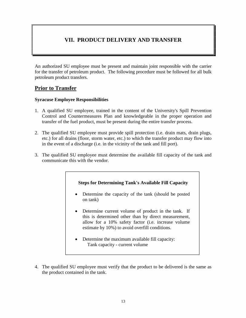
13
VII. PRODUCT DELIVERY AND TRANSFER
An authorized SU employee must be present and maintain joint responsible with the carrier for the transfer of petroleum product. The following procedure must be followed for all bulk petroleum product transfers. Prior to Transfer Syracuse Employee Responsibilities 1. A qualified SU employee, trained in the content of the University's Spill Prevention
Control and Countermeasures Plan and knowledgeable in the proper operation and transfer of the fuel product, must be present during the entire transfer process.
2. The qualified SU employee must provide spill protection (i.e. drain mats, drain plugs,
etc.) for all drains (floor, storm water, etc.) to which the transfer product may flow into in the event of a discharge (i.e. in the vicinity of the tank and fill port).
3. The qualified SU employee must determine the available fill capacity of the tank and
communicate this with the vendor.
Steps for Determining Tank's Available Fill Capacity
• Determine the capacity of the tank (should be posted on tank)
• Determine current volume of product in the tank. If
this is determined other than by direct measurement, allow for a 10% safety factor (i.e. increase volume estimate by 10%) to avoid overfill conditions.
• Determine the maximum available fill capacity:
Tank capacity - current volume 4. The qualified SU employee must verify that the product to be delivered is the same as
the product contained in the tank.
14
5. The qualified SU employee must verify that the vendor's representative is qualified, knowledgeable and trained in the proper operation and delivery of the fuel product.
6. The qualified SU employee must ensure that traffic in the immediate vicinity of the
transfer process is effectively controlled or eliminated during the transfer process. 7. The qualified SU employee should verify that the vendor's vehicle is appropriately
grounded during the transfer process. 8. The qualified SU employee must assure adequate communication with the vendor
during the transfer process (i.e. 2-way radios set at a designated frequency, etc.) 9. Once all of the above steps are completed, the qualified SU employee should then
unlock the tank's fill port. 10. The qualified SU employee must monitor the tank site during the entire fill procedure
to ensure that the tank is not over filled and/or that pipes are not leaking. Prior to Transfer Vendor Responsibilities 1. The vendor may not hook up or transfer any petroleum product unless a qualified
University representative who is trained in the proper operation and delivery of the fuel product is present during the entire transfer process.
2. The vendor may not hook up or transfer any petroleum product unless a qualified
vendor representative who is trained in the proper operation and delivery of the fuel product is present during the entire transfer process.
3. The vendor's qualified representative must verify the integrity of the tank and its
storage location. 4. The vendor's qualified representative must verify that the tank vent is open and
unobstructed. 5. The vendor's qualified representative must determine available fill capacity of the tank
and then verify it with the SU employee. 6. The vendor's qualified representative must verify with the SU employee that the
product to be delivered is the same as what is presently in the tank. 7. The vendor's qualified representative must inspect their vehicle and all equipment to be
used during the transfer procedure (i.e. vehicle drain, outlet connections, transfer hose, equipment, etc.) to assure that they are functioning properly.
15
Note: All liquid transfer equipment (hoses and piping) must contain valves which close automatically and provide a dry disconnection or other means or preventing a release of the product to the environment when transfer hoses or pipes are disconnected.
8. The vendor's qualified representative must appropriately ground the vehicle. It is the
policy of Syracuse University that vehicles must be grounded at all times during the transfer of petroleum products.
9. The vendor's qualified representative must be readily able to communicate with the SU
employee during the fill process. 10. The vendor's qualified representative must remain at the fill location during the entire
transfer process. Prior to Departure Syracuse Employee Responsibilities 1. The qualified SU employee must ensure that all of the vendor's fill equipment has been
removed from the fill port. 2. The qualified SU employee must inspect the fill area to ensure no residual product
remains in or around the fill area. If any is found the qualified SU employee must notify EHSS (X-4132) and the vendor's representative immediately.
3. The qualified SU employee must recap and lock the fill port. 4. The qualified SU employee must retrieve the drain protectors and them place back in
their appropriate storage area(s) Vendor Responsibilities 1. The vendor's qualified representative must properly disconnect all transfer hoses and
provide assurance for the capture of residual product without discharge to the environment.
2. The vendor's qualified representative must inspect the fill area to ensure no residual
product remains in or around the fill area. The vendor is responsible for delivery related spill clean up.
Note: Petroleum product transfers should be made during normal SU operating hours to help ensure appropriate response in the event of a discharge/spill.
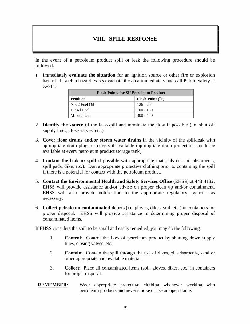
16
VIII. SPILL RESPONSE
In the event of a petroleum product spill or leak the following procedure should be followed. 1. Immediately evaluate the situation for an ignition source or other fire or explosion
hazard. If such a hazard exists evacuate the area immediately and call Public Safety at X-711.
Flash Points for SU Petroleum Product Product Flash Point (oF) No. 2 Fuel Oil 126 - 204 Diesel Fuel 100 - 130 Mineral Oil 300 - 450
2. Identify the source of the leak/spill and terminate the flow if possible (i.e. shut off
supply lines, close valves, etc.) 3. Cover floor drains and/or storm water drains in the vicinity of the spill/leak with
appropriate drain plugs or covers if available (appropriate drain protection should be available at every petroleum product storage tank).
4. Contain the leak or spill if possible with appropriate materials (i.e. oil absorbents,
spill pads, dike, etc.). Don appropriate protective clothing prior to containing the spill if there is a potential for contact with the petroleum product.
5. Contact the Environmental Health and Safety Services Office (EHSS) at 443-4132.
EHSS will provide assistance and/or advise on proper clean up and/or containment. EHSS will also provide notification to the appropriate regulatory agencies as necessary.
6. Collect petroleum contaminated debris (i.e. gloves, dikes, soil, etc.) in containers for
proper disposal. EHSS will provide assistance in determining proper disposal of contaminated items.
If EHSS considers the spill to be small and easily remedied, you may do the following: 1. Control: Control the flow of petroleum product by shutting down supply
lines, closing valves, etc. 2. Contain: Contain the spill through the use of dikes, oil adsorbents, sand or
other appropriate and available material. 3. Collect: Place all contaminated items (soil, gloves, dikes, etc.) in containers
for proper disposal. REMEMBER: Wear appropriate protective clothing whenever working with
petroleum products and never smoke or use an open flame.
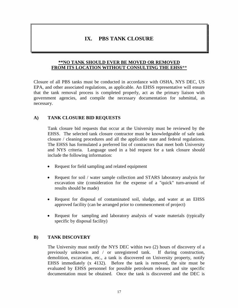
17
IX. PBS TANK CLOSURE
**NO TANK SHOULD EVER BE MOVED OR REMOVED
FROM ITS LOCATION WITHOUT CONSULTING THE EHSS** Closure of all PBS tanks must be conducted in accordance with OSHA, NYS DEC, US EPA, and other associated regulations, as applicable. An EHSS representative will ensure that the tank removal process is completed properly, act as the primary liaison with government agencies, and compile the necessary documentation for submittal, as necessary. A) TANK CLOSURE BID REQUESTS Tank closure bid requests that occur at the University must be reviewed by the EHSS. The selected tank closure contractor must be knowledgeable of safe tank closure / cleaning procedures and all the applicable state and federal regulations. The EHSS has formulated a preferred list of contractors that meet both University and NYS criteria. Language used in a bid request for a tank closure should include the following information:
• Request for field sampling and related equipment • Request for soil / water sample collection and STARS laboratory analysis for
excavation site (consideration for the expense of a "quick" turn-around of results should be made)
• Request for disposal of contaminated soil, sludge, and water at an EHSS
approved facility (can be arranged prior to commencement of project) • Request for sampling and laboratory analysis of waste materials (typically
specific by disposal facility)
B) TANK DISCOVERY The University must notify the NYS DEC within two (2) hours of discovery of a previously unknown and / or unregistered tank. If during construction, demolition, excavation, etc., a tank is discovered on University property, notify EHSS immediately (x 4132). Before the tank is removed, the site must be evaluated by EHSS personnel for possible petroleum releases and site specific documentation must be obtained. Once the tank is discovered and the DEC is
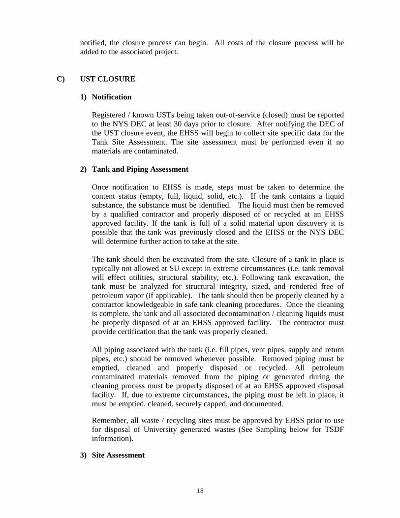
18
notified, the closure process can begin. All costs of the closure process will be added to the associated project. C) UST CLOSURE 1) Notification
Registered / known USTs being taken out-of-service (closed) must be reported to the NYS DEC at least 30 days prior to closure. After notifying the DEC of the UST closure event, the EHSS will begin to collect site specific data for the Tank Site Assessment. The site assessment must be performed even if no materials are contaminated.
2) Tank and Piping Assessment
Once notification to EHSS is made, steps must be taken to determine the content status (empty, full, liquid, solid, etc.). If the tank contains a liquid substance, the substance must be identified. The liquid must then be removed by a qualified contractor and properly disposed of or recycled at an EHSS approved facility. If the tank is full of a solid material upon discovery it is possible that the tank was previously closed and the EHSS or the NYS DEC will determine further action to take at the site. The tank should then be excavated from the site. Closure of a tank in place is typically not allowed at SU except in extreme circumstances (i.e. tank removal will effect utilities, structural stability, etc.). Following tank excavation, the tank must be analyzed for structural integrity, sized, and rendered free of petroleum vapor (if applicable). The tank should then be properly cleaned by a contractor knowledgeable in safe tank cleaning procedures. Once the cleaning is complete, the tank and all associated decontamination / cleaning liquids must be properly disposed of at an EHSS approved facility. The contractor must provide certification that the tank was properly cleaned. All piping associated with the tank (i.e. fill pipes, vent pipes, supply and return pipes, etc.) should be removed whenever possible. Removed piping must be emptied, cleaned and properly disposed or recycled. All petroleum contaminated materials removed from the piping or generated during the cleaning process must be properly disposed of at an EHSS approved disposal facility. If, due to extreme circumstances, the piping must be left in place, it must be emptied, cleaned, securely capped, and documented. Remember, all waste / recycling sites must be approved by EHSS prior to use for disposal of University generated wastes (See Sampling below for TSDF information).
3) Site Assessment
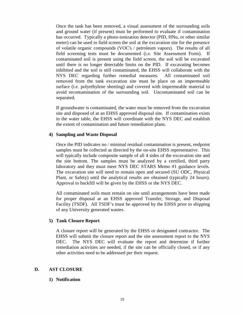
19
Once the tank has been removed, a visual assessment of the surrounding soils and ground water (if present) must be performed to evaluate if contamination has occurred. Typically a photo-ionization detector (PID, HNu, or other similar meter) can be used to field screen the soil at the excavation site for the presence of volatile organic compounds (VOC's / petroleum vapors). The results of all field screening tests must be documented (i.e. Site Assessment Form). If contaminated soil is present using the field screen, the soil will be excavated until there is no longer detectable limits on the PID. If excavating becomes inhibited and the soil is still contaminated, the EHSS will collaborate with the NYS DEC regarding further remedial measures. All contaminated soil removed from the tank excavation site must be place on an impermeable surface (i.e. polyethylene sheeting) and covered with impermeable material to avoid recontamination of the surrounding soil. Uncontaminated soil can be separated. If groundwater is contaminated, the water must be removed from the excavation site and disposed of at an EHSS approved disposal site. If contamination exists in the water table, the EHSS will coordinate with the NYS DEC and establish the extent of contamination and future remediation plans.
4) Sampling and Waste Disposal
Once the PID indicates no / minimal residual contamination is present, endpoint samples must be collected as directed by the on-site EHSS representative. This will typically include composite sample of all 4 sides of the excavation site and the site bottom. The samples must be analyzed by a certified, third party laboratory and they must meet NYS DEC STARS Memo #1 guidance levels. The excavation site will need to remain open and secured (SU ODC, Physical Plant, or Safety) until the analytical results are obtained (typically 24 hours). Approval to backfill will be given by the EHSS or the NYS DEC. All contaminated soils must remain on site until arrangements have been made for proper disposal at an EHSS approved Transfer, Storage, and Disposal Facility (TSDF). All TSDF’s must be approved by the EHSS prior to shipping of any University generated wastes.
5) Tank Closure Report
A closure report will be generated by the EHSS or designated contractor. The EHSS will submit the closure report and the site assessment report to the NYS DEC. The NYS DEC will evaluate the report and determine if further remediation activities are needed, if the site can be officially closed, or if any other activities need to be addressed per their request.
D. AST CLOSURE 1) Notification
20
Registered / known ASTs being taken out-of-service (closed) need to be reported to the NYS DEC within 30 days prior to closure. The EHSS will notify the NYS DEC and will designate when removal can begin. 2) Tank and Piping
Any liquid or sludge in the tank must be identified and properly removed from the tank. The liquid and waste materials must be collected and disposed of or recycled at an EHSS approved facility. Once the tank is empty, it must be rendered free of petroleum vapors. If the AST meets the NYS DEC standards for a new tank, it can be cleaned tested and reused. If the tank is to be disposed or recycled it must be retested for petroleum vapors and cleaned by a contractor knowledgeable in safe tank cleaning procedures. The contractor must supply certification that the tank was cleaned properly. Prior to leaving the site for disposal the tank should also be stenciled with the date of permanent closure and punctured with holes to guarantee no future usage. All piping associated with the tank (i.e. fill pipes, vent pipes, supply and return pipes, etc.) should be removed whenever possible. Removed piping must be emptied, cleaned and disposed of with the tank. All petroleum contaminated materials removed from the piping or generated during the cleaning process must be properly disposed of at an EHSS approved disposal facility. If, due to extreme circumstances, the piping must be left in place, it must be emptied, cleaned and securely capped. The project manager must document the rationale for leaving pipe in place.
3) Tank Closure Report
A closure report for all ASTs will be generated by the EHSS or designated contractor. The EHSS will submit the closure report and the site assessment report to the NYS DEC. The NYS DEC will evaluate the report and determine if the site can be officially closed or if any other activities need to be addressed per their request.
E. REGISTRATION MODIFICATION If a registered SU tank is closed, the EHSS will modify the registration to indicate the tank closure. When the new registration is received from the NYS DEC, the EHSS will redistribute it for proper placement, where applicable.
21
X. NEW AND SUBSTANTIALLY MODIFIED
PETROLEUM BULK STORAGE SYSTEMS
A. NOTIFICATION The NYS DEC requires notification a minimum of 30 days prior to the installation of a new PBS System or any substantial modifications. Furthermore, the Syracuse Fire Marshal needs to be notified at least 24 hours before any tank installation, major modification, or closure. The EHSS should be notified as soon as a modification or new system installation is considered so the EHSS can make all of the applicable contacts. B. PROJECT APPROVAL New and substantial modifications must meet or exceed standards set by the NYS DEC regulations (§ Part 612-614). The EHSS will review for approval new installations and modifications before construction. See Section II for Registration Requirements for new and substantially modified PBS systems. See Section VIII for proper spill procedures that may occur during a PBS modification.
22
XI. TEMPORARY AND PORTABLE PETROLEUM BULK STORAGE TANKS
A. TEMPORARY TANKS A temporary tank is a tank that is rendered immobile by affixing it to one location (i.e. wired, plugged in, hard piped, etc.). The EHSS must be notified of the intent to place, use, or install any temporary tanks prior to placement on University owned or operated property. No tank may be placed without prior EHSS review and approval. The EHSS will verify if the temporary tank requires NYS DEC registration and as necessary will submit applicable documentation to the NYS DEC. A temporary tank must be registered with the NYS DEC when it is at a facility with an aggregate bulk petroleum storage capacity exceeding 1,100 gallons. If the addition of a temporary tank causes a facility to exceed a 1,100 gallons aggregate bulk petroleum storage capacity, all of the tanks at that facility (permanent and temporary) will require registration in accordance with the NYS DEC regulations (§ Part 612). While in service, a registered temporary tank must have the ancillary equipment required for a NYS DEC registered tank (See Sections IV and V). The EHSS will conduct and document an initial inspection of all registered temporary tanks. In addition, a trained SU tank inspector appointed by the department responsible for use of the tank, will perform routine monthly inspections on temporary tanks used, placed, or operational for a thirty (30) day period or greater (See Section VI). Unregistered temporary tanks must also have the ancillary equipment required for NYS DEC registered tanks wherever feasible. All temporary tanks with a capacity of 55 gallons or greater, that are used or stored in areas which require oil SPCC Plans (i.e. Main Campus and Ainsley Drive facilities), must meet all applicable SPCC Plan requirements and have a product transfer / delivery procedure reviewed and approved by the EHSS. B. PORTABLE TANKS AND CONTAINERS The NYS DEC classifies a petroleum bulk storage tank as portable when it is designed to be moveable and has no connections affixing the tank to one location. Truck bed tanks and skid tanks are two examples of portable tanks. Portable petroleum storage tanks and containers do not need to be registered with the NYS DEC but must still be properly handled while at the University. Portable tanks and containers with a capacity of 55 gallons or greater that are used or stored in areas with an oil SPCC Plan (i.e. Main Campus and Ainsley Drive facilities) must be provided with adequate secondary containment. As a recommended practice, portable tanks less than (fifty-five) 55 gallons or larger tanks in areas without an oil SPCC Plan should also be provided with an adequate form of
23
secondary containment where feasible. All portable tanks must be transported in compliance with all Department of Transportation (DOT) requirements. The SU Spill Response protocol must be followed for any petroleum spill at the University (See Section VIII). If there is a petroleum spill of any quantity associated with portable tanks, containers, or temporary tanks, the EHSS must be contacted immediately. SU Safety should be contacted at X-5474 for additional Fire and Safety matters concerning temporary tanks and portable containers.
APPENDICES
APPENDIX A:
INSPECTION DOMUMENTS
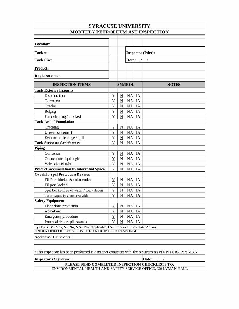
Location:
Tank #: Inspector (Print):
Tank Size:
Product:
Registration #:
NOTES
Discoloration Y N NA IACorrosion Y N NA IACracks Y N NA IABulging Y N NA IAPaint chipping / cracked Y N NA IA
Cracking Y N NA IAUneven settlement Y N NA IAEvidence of leakage / spill Y N NA IA
Tank Supports Satisfactory Y N NA IA
Corrosion Y N NA IAConnections liquid tight Y N NA IAValves liquid tight Y N NA IA
Product Accumulation In Interstitial Space Y N NA IAOverfill / Spill Protection Devices
Fill Port labeled & color coded Y N NA IAFill port locked Y N NA IASpill bucket free of water / fuel / debris Y N NA IATank capacity chart available Y N NA IA
Safety EquipmentFloor drain protection Y N NA IAAbsorbent Y N NA IAEmergency procedure Y N NA IAPotential fire or spill hazards Y N NA IA
*This inspection has been performed in a manner consistent with the requirements of 6 NYCRR Part 613.6
Date: / /PLEASE SEND COMPLETED INSPECTION CHECKLISTS TO:
ENVIRONMENTAL HEALTH AND SAFETY SERVICE OFFICE, 029 LYMAN HALL
Inspector's Signature:
Symbols: Y= Yes, N= No, NA= Not Applicable, IA= Requires Immediate ActionUNDERLINED RESPONSE IS THE ANTICIPATED RESPONSE Additional Comments:
Tank Area / Foundation
Piping
SYRACUSE UNIVERSITYMONTHLY PETROLEUM AST INSPECTION
SYMBOLTank Exterior Integrity
INSPECTION ITEMS
Date: / /
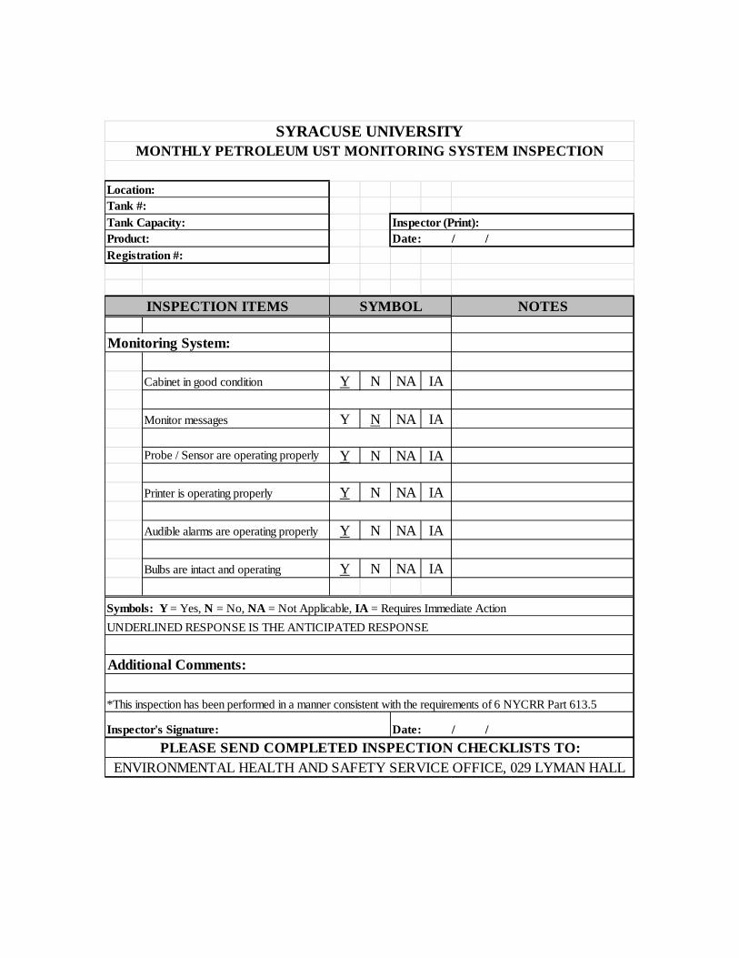
Location:Tank #: Tank Capacity:Product:
NOTES
Monitoring System:
Cabinet in good condition Y N NA IA
Monitor messages Y N NA IA
Probe / Sensor are operating properly Y N NA IA
Printer is operating properly Y N NA IA
Audible alarms are operating properly Y N NA IA
Bulbs are intact and operating Y N NA IA
Symbols: Y = Yes, N = No, NA = Not Applicable, IA = Requires Immediate Action
*This inspection has been performed in a manner consistent with the requirements of 6 NYCRR Part 613.5
SYRACUSE UNIVERSITYMONTHLY PETROLEUM UST MONITORING SYSTEM INSPECTION
SYMBOLINSPECTION ITEMS
Date: / /Inspector (Print):
Registration #:
Additional Comments:
UNDERLINED RESPONSE IS THE ANTICIPATED RESPONSE
PLEASE SEND COMPLETED INSPECTION CHECKLISTS TO:ENVIRONMENTAL HEALTH AND SAFETY SERVICE OFFICE, 029 LYMAN HALL
Inspector's Signature: Date: / /
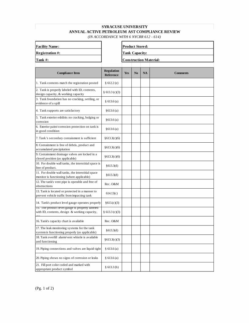
Facility Name:
Registration #:
Tank #:
Compliance ItemRegulation Reference Yes No NA Comments
1. Tank contents match the registration posted § 612.2 (e)
2. Tank is properly labeled with ID, contents, design capacity, & working capacity § 613.3 (c)(3)
3. Tank foundation has no cracking, settling, or evidence of a spill § 613.6 (a)
4. Tank supports are satisfactory §613.6 (a)
5. Tank exterior exhibits no cracking, bulging or corrosion §613.6 (a)
6. Exterior paint/corrosion protection on tank is in good condition §613.6 (a)
7. Tank 's secondary containment is sufficient §613.3(c)(6)
8. Containment is free of debris, product and accumulated precipitation §613.3(c)(6)
9. Containment drainage valves are locked in a closed position (as applicable) §613.3(c)(6)
10. For double wall tanks, the interstitial space is free of product. §613.3(d)
11. For double wall tanks, the interstitial space monitor is functioning (where applicable) §613.3(d)
12. The tank's vent pipe is operable and free of obstructions Rec. O&M
13. Tank is located or protected in a manner to prevent vehicle traffic from impacting tank
614.13(c)
14. Tank's product level gauge operates properly §613.(c)(3)15. The product level gauge is properly labeled with ID, contents, design & working capacity, etc
§ 613.3 (c)(3)
16. Tank's capacity chart is available Rec. O&M
17. The leak monitoring systems for the tank system is functioning properly (as applicable) §613.3(d)
18. Tank overfill alarm/vent whistle is available and functioning §613.3(c)(3)
19. Piping connections and valves are liquid tight § 613.6 (a)
20. Piping shows no signs of corrosion or leaks § 613.6 (a)
21. Fill port color coded and marked with appropriate product symbol § 613.3 (b)
SYRACUSE UNIVERSITYANNUAL ACTIVE PETROLEUM AST COMPLIANCE REVIEW
(IN ACCORDANCE WITH 6 NYCRR 612 - 614)
Product Stored:
Tank Capacity:
Construction Material:
(Pg. 1 of 2)
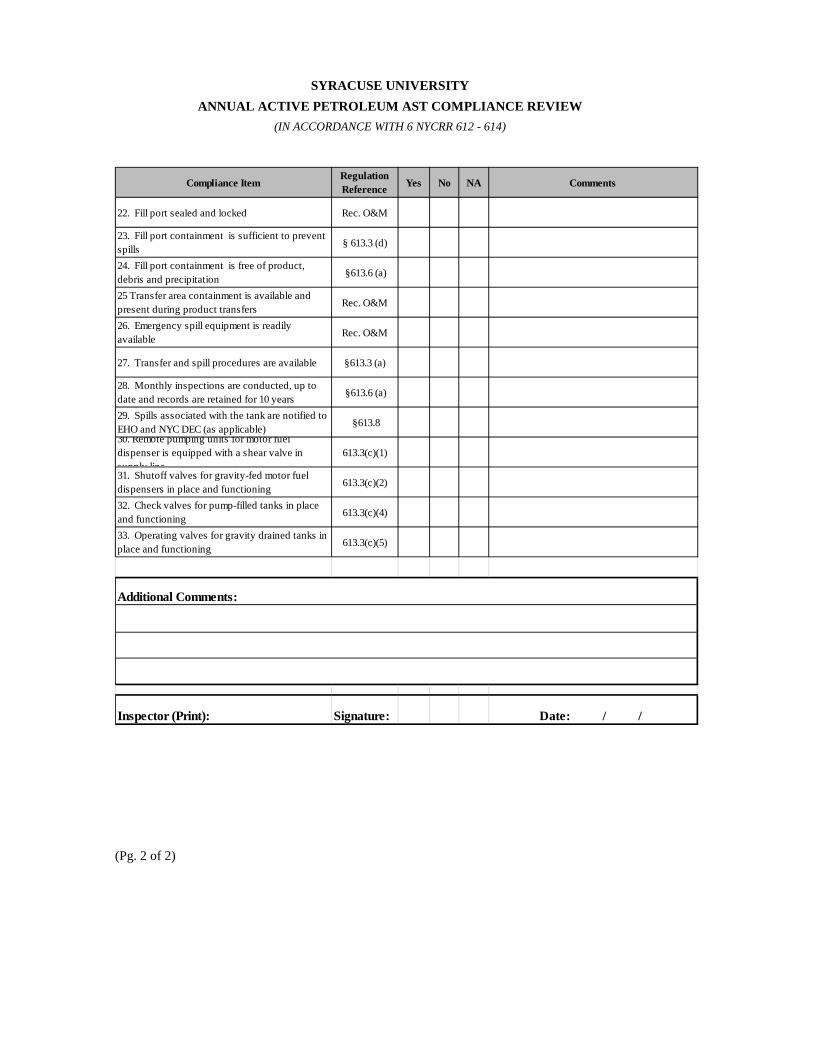
SYRACUSE UNIVERSITY ANNUAL ACTIVE PETROLEUM AST COMPLIANCE REVIEW (IN ACCORDANCE WITH 6 NYCRR 612 - 614)
Compliance ItemRegulation Reference Yes No NA Comments
22. Fill port sealed and locked Rec. O&M
23. Fill port containment is sufficient to prevent spills § 613.3 (d)
24. Fill port containment is free of product, debris and precipitation §613.6 (a)
25 Transfer area containment is available and present during product transfers Rec. O&M
26. Emergency spill equipment is readily available Rec. O&M
27. Transfer and spill procedures are available §613.3 (a)
28. Monthly inspections are conducted, up to date and records are retained for 10 years §613.6 (a)
29. Spills associated with the tank are notified to EHO and NYC DEC (as applicable) §613.830. Remote pumping units for motor fuel dispenser is equipped with a shear valve in supply line
613.3(c)(1)
31. Shutoff valves for gravity-fed motor fuel dispensers in place and functioning 613.3(c)(2)
32. Check valves for pump-filled tanks in place and functioning 613.3(c)(4)
33. Operating valves for gravity drained tanks in place and functioning 613.3(c)(5)
Inspector (Print): Signature: Date: / /
Additional Comments:
(Pg. 2 of 2)
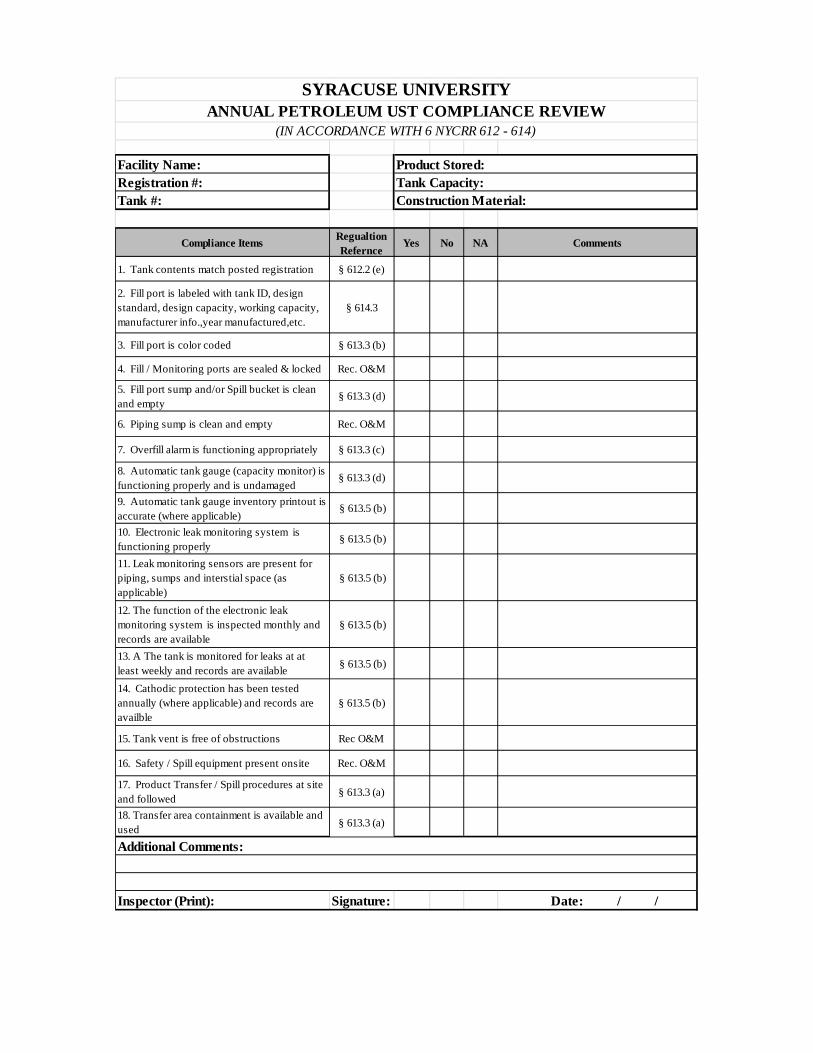
Facility Name: Registration #: Tank #:
Compliance Items Regualtion Refernce
Yes No NA Comments
1. Tank contents match posted registration § 612.2 (e)
2. Fill port is labeled with tank ID, design standard, design capacity, working capacity, manufacturer info.,year manufactured,etc.
§ 614.3
3. Fill port is color coded § 613.3 (b)
4. Fill / Monitoring ports are sealed & locked Rec. O&M
5. Fill port sump and/or Spill bucket is clean and empty
§ 613.3 (d)
6. Piping sump is clean and empty Rec. O&M
7. Overfill alarm is functioning appropriately § 613.3 (c)
8. Automatic tank gauge (capacity monitor) is functioning properly and is undamaged
§ 613.3 (d)
9. Automatic tank gauge inventory printout is accurate (where applicable)
§ 613.5 (b)
10. Electronic leak monitoring system is functioning properly
§ 613.5 (b)
11. Leak monitoring sensors are present for piping, sumps and interstial space (as applicable)
§ 613.5 (b)
12. The function of the electronic leak monitoring system is inspected monthly and records are available
§ 613.5 (b)
13. A The tank is monitored for leaks at at least weekly and records are available § 613.5 (b)
14. Cathodic protection has been tested annually (where applicable) and records are availble
§ 613.5 (b)
15. Tank vent is free of obstructions Rec O&M
16. Safety / Spill equipment present onsite Rec. O&M
17. Product Transfer / Spill procedures at site and followed § 613.3 (a)
18. Transfer area containment is available and used § 613.3 (a)
Inspector (Print): Signature: Date: / /
SYRACUSE UNIVERSITYANNUAL PETROLEUM UST COMPLIANCE REVIEW
(IN ACCORDANCE WITH 6 NYCRR 612 - 614)
Additional Comments:
Construction Material: Tank Capacity: Product Stored:
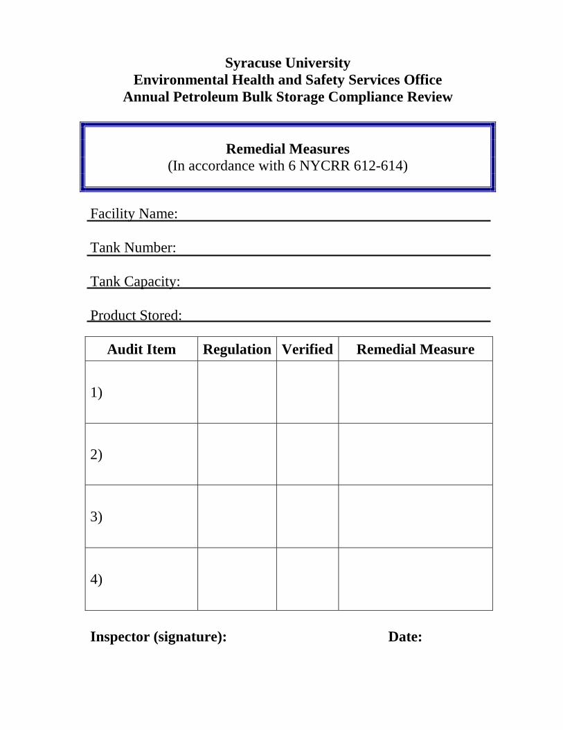
Syracuse University Environmental Health and Safety Services Office
Annual Petroleum Bulk Storage Compliance Review
Remedial Measures (In accordance with 6 NYCRR 612-614)
Facility Name: Tank Number: Tank Capacity: Product Stored:
Audit Item Regulation Verified Remedial Measure
1)
2)
3)
4)
Inspector (signature): Date:
APPENDIX B:
AMERICAN PETROLEUM INSTITUTE FILL PORT COLOR CODING AND SYMBOLS
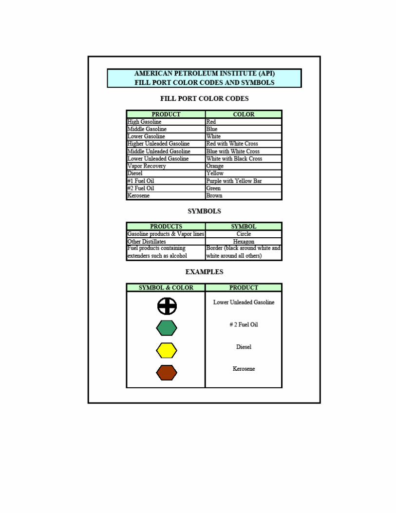
APPENDIX C:
AFTER-HOUR OIL SPILL RESPONSE PROTOCOL
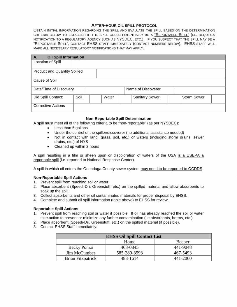
AFTER-HOUR OIL SPILL PROTOCOL OBTAIN INITIAL INFORMATION REGARDING THE SPILL AND EVALUATE THE SPILL BASED ON THE DETERMINATION CRITERIA BELOW TO ESTABLISH IF THE SPILL COULD POTENTIALLY BE A “REPORTABLE SPILL” (I.E. REQUIRES NOTIFICATION TO A REGULATORY AGENCY SUCH AS NYSDEC, ETC.). IF YOU SUSPECT THAT THE SPILL MAY BE A “REPORTABLE SPILL”, CONTACT EHSS STAFF IMMEDIATELY (CONTACT NUMBERS BELOW). EHSS STAFF WILL MAKE ALL NECESSARY REGULATORY NOTIFICATIONS THAT MAY APPLY. A. Oil Spill Information Location of Spill
Product and Quantity Spilled
Cause of Spill
Date/Time of Discovery Name of Discoverer
Did Spill Contact: Soil Water Sanitary Sewer Storm Sewer
Corrective Actions
Non-Reportable Spill Determination
A spill must meet all of the following criteria to be “non-reportable” (as per NYSDEC): • Less than 5 gallons • Under the control of the spiller/discoverer (no additional assistance needed) • Not in contact with land (grass, soil, etc.) or waters (including storm drains, sewer
drains, etc.) of NYS • Cleaned up within 2 hours
A spill resulting in a film or sheen upon or discoloration of waters of the USA is a USEPA a reportable spill (i.e. reported to National Response Center). A spill in which oil enters the Onondaga County sewer system may need to be reported to OCDDS. Non-Reportable Spill Actions 1. Prevent spill from reaching soil or water. 2. Place absorbent (Speedi-Dri, Greenstuff, etc.) on the spilled material and allow absorbents to
soak up the spill. 3. Collect absorbents and other oil contaminated materials for proper disposal by EHSS. 4. Complete and submit oil spill information (table above) to EHSS for review. Reportable Spill Actions 1. Prevent spill from reaching soil or water if possible. If oil has already reached the soil or water
take action to prevent or minimize any further contamination (i.e absorbants, berms, etc.) 2. Place absorbent (Speedi-Dri, Greenstuff, etc.) on the spilled material (if possible). 3. Contact EHSS Staff immediately:
EHSS Oil Spill Contact List
Home Beeper Becky Ponza 468-0845 441-9048
Jim McCumber 585-289-3593 467-5493 Brian Fitzpatrick 488-1614 441-2060
APPEN DIX C
Inspection Forms
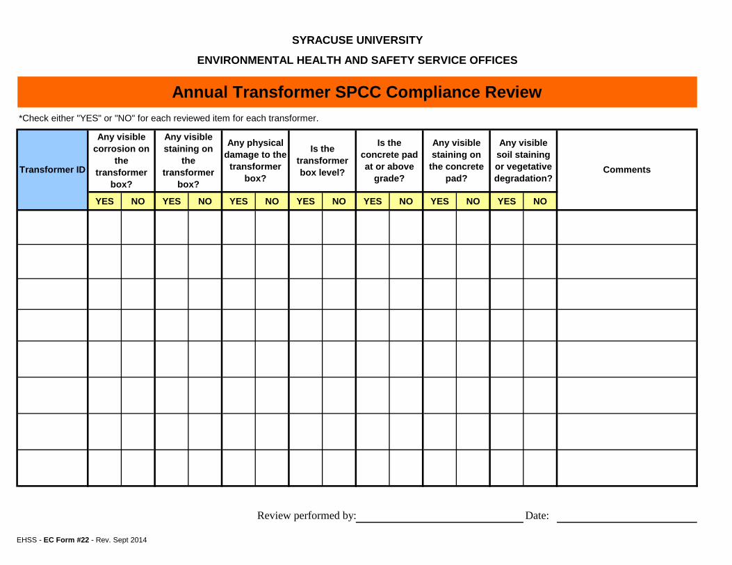
EHSS - EC Form #22 - Rev. Sept 2014
YES NO YES NO YES NO YES NO YES NO YES NO YES NO
Review performed by: Date:
Any visible staining on
the concrete pad?
Any visible soil staining or vegetative degradation?
Transformer ID
Any visible corrosion on
the transformer
box?
Any visible staining on
the transformer
box?
Any physical damage to the
transformer box?
Is the transformer box level?
Is the concrete pad at or above
grade?
SYRACUSE UNIVERSITY
ENVIRONMENTAL HEALTH AND SAFETY SERVICE OFFICES
Annual Transformer SPCC Compliance Review*Check either "YES" or "NO" for each reviewed item for each transformer.
Comments
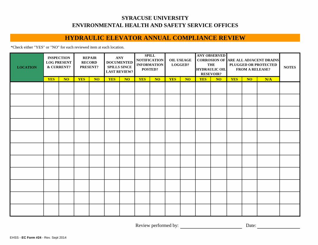
EHSS - EC Form #24 - Rev. Sept 2014
YES NO YES NO YES NO YES NO YES NO YES NO YES NO N/A
Date:Review performed by:
SYRACUSE UNIVERSITYENVIRONMENTAL HEALTH AND SAFETY SERVICE OFFICES
HYDRAULIC ELEVATOR ANNUAL COMPLIANCE REVIEW*Check either "YES" or "NO" for each reviewed item at each location.
LOCATION NOTES
ANY OBSERVED CORROSION OF
THE HYDRAULIC OIL
RESEVOIR?
ARE ALL ADJACENT DRAINS PLUGGED OR PROTECTED
FROM A RELEASE?
INSPECTION LOG PRESENT & CURRENT?
REPAIR RECORD
PRESENT?
ANY DOCUMENTED SPILLS SINCE
LAST REVIEW?
SPILL NOTIFICATION INFORMATION
POSTED?
OIL USEAGE LOGGED?
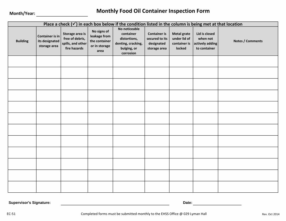
EC-51 Completed forms must be submitted monthly to the EHSS Office @ 029 Lyman Hall Rev. Oct 2014
Supervisor's Signature: Date:
Container is in its designated storage area
Monthly Food Oil Container Inspection Form
Container is secured to its
designated storage area
Metal grate under lid of container is
locked
Building
Storage area is free of debris,
spills, and other fire hazards
No signs of leakage from the container or in storage
area
No noticeable container
distortions, denting, cracking,
bulging, or corrosion
Lid is closed when not
actively adding to container
Month/Year:
Notes / Comments
Place a check () in each box below if the condition listed in the column is being met at that location