spin-on filter mf/mfd up to 300 l/min, up to 8 bar · 201 011012 spin-on filter mf/mfd up to 300...
TRANSCRIPT

201
E 7.
301.
16/0
3.12
Spin-On Filter MF/MFD up to 300 l/min, up to 8 bar
1. TECHNiCAL SPECiFiCATiONS
1.1 FiLTER HOUSiNGConstruction The filter consists of a filter head with built-in bypass valve and a screw-on filter cartridge.Standard equipment:
with bypass valve1.2 FiLTER CARTRiDGES
MG: Cartridge connection thread, to ISO 228 Sealing on inside (Note: the seal on the 0080 MA cartridge is also on the inside!)MA: Cartridge connection, UN thread sealing on the outside
1.4 SEALSNBR (= Perbunan)
1.5 iNSTALLATiON As inline filter
1.6 SPECiAL MODELS AND ACCESSORiESWithout bypass or with other bypass cracking pressures
1.7 SPARE PARTSSee Original Spare Parts List
1.8 CERTiFiCATES AND APPROVALSOn request
1.3 FiLTER SPECiFiCATiONS
Nominal pressure 8 bar Temperature range -30 °C to +100 °C Pressure setting of clogging indicator: ∆pa Type E: 0 to 16 bar Type F: 1.5 or 2 bar Type UE: 0 to -1.0 bar Type UF: -0.2 bar Type of clogging indicator VMF (return line indication) Material of filter head Aluminium Material of filter cartridge Sheet steel Cracking pressure of bypass valve 1.7 bar (standard for size 80) 2 bar (standard for size 160/180)
Symbol for hydraulic systems
MF 80
MF 160
MF 180
MFD 160
MFD 180
E 7.
301.
16/0
3.12
Seals Seals
1.9 COMPATiBiLiTY WiTH HYDRAULiC FLUiDS iSO 2943
Hydraulic oils to DIN 51524Lubrication oils DIN 51517, API,
ACEA, DIN 51515, ISO 6743Compressor oils DIN 51506Biodegradable operating fluids VDMA
24568 HETG, HEES, HEPGFire-resistant fluids HFA, HFB, HFC
and HFDOperating fluids with high water
content (>50% water content) on request

E 7.
301.
16/0
3.12
202
2. MODEL CODE (also order example)2.1 COMPLETE FiLTER
0160 MA 010 BN
Size 0080, 0160, 0180Type MG for filters with cartridge connection G (= thread to ISO 228); paper filter material only (exception: MF 80: 20 BN) MA for filters with cartridge connection U (= UN thread)Filtration rating in µm BN 003, 005, 010, 020 (for MF 80: MA = only 10 µm; MG = 20 µm) P 010Filter material BN, P
2.2 REPLACEMENT CARTRiDGE
2.3 REPLACEMENT CLOGGiNG iNDiCATOR VMF 2 F . X
Type of indicator VMF return line pressure indicatorPressure setting 2 2 bar standard for size 160/180 (see Point 1.3) 1.5 1.5 bar standard for size 80Type of clogging indicator F (see Point 2.1)Modification number X the latest version is always supplied
Filter type MF (all sizes; 1 filter cartridge) MFD (sizes 160 and 180; 2 filter cartridges)Filter material BN Betamicron® P Paper (only MF 80 and MF/MFD 160)Size of filter or cartridge MF: 80, 160, 180 MFD: 160, 180
Operating pressure A 8 bar
Type of cartridge connection G thread to ISO 228 (G ¾ on size 80; G 1¼ on size 160/180) U UN thread (1-12 UNF, 1½ x 16 UN-2B)Type and size of port
MF BN 160 A U E 10 F 1 .X /-KB
Filtration rating in µm BN 3, 5, 10, 20 P 10Type of clogging indicator A steel blanking plug in indicator port E pressure gauge pressure indicators F pressure switch for other clogging indicators UE vacuum gauge vacuum indicators see brochure no. 7.050../.. UF vacuum switchType code 0 1 - 8 see Point 2.4Modification number X the latest version is always suppliedSupplementary details B. cracking pressure of bypass (e.g. B0.2 = 0.2 bar; B0.25 = 0.25 bar) KB without bypass valve (only for size 160/180)
Type Connection Filter size80 160 180
C G ¾ MF – –E G1 ¼ – MF MFF G1 ½ – MFD MFD

203
E 7.
301.
16/0
3.12
2.4 MOUNTiNG POSiTiON OF THE CLOGGiNG iNDiCATORMF 80 MF 160/180 MFD 160/180
For MF-FilterType Mounting position of Application of Type of Specials code clogging indicator complete filter indicator0.X Without clogging indicator, blanking plug in all indicator ports –1.X Filter inlet: on left Return line filter Pressure indicator –2.X Filter inlet: on right Return line filter Pressure indicator –3.X Filter outlet: on left Suction filter Vacuum indicator Only for sizes 160 and 180, on versions: - with bypass cracking pressure 0.2 bar (.../-B0.2) - without bypass valve (.../-KB)4.X Filter outlet: on right Suction filter Vacuum indicator Only for sizes 160 and 180, on versions: - with bypass cracking pressure 0.2 bar (.../-B0.2) - without bypass valve (.../-KB)5.X Filter inlet & outlet: on left Pressure filter Pressure and – vacuum indicator6.X Filter inlet & outlet: on right Pressure filter Pressure and – vacuum indicator7.X Filter inlet: on right and left Return line filter Pressure indicator –8.X Filter outlet: on right and left Suction filter Vacuum indicator Only for sizes 160 und 180, on versions: - with bypass cracking pressure 0.2 bar (.../-B0.2) - without bypass valve (.../-KB) For MFD filtersType Mounting position of Application of Type of Specials code clogging indicator complete filter indicator0.X Without clogging indicator, blanking plug in all indicator ports –1.X Filter inlet: on right Return line filter Pressure indicator –3.X Filter outlet: on right Suction filter Vacuum indicator Only on versions: - with bypass cracking pressure 0.2 bar (.../-B0.2) - without bypass valve (.../-KB)5.X Filter inlet & outlet: on right Pressure filter Pressure and – vacuum indicator
2.5 CARTRiDGE SELECTiON TABLEFilter type MFSize 80 CartridgeMF P 80 AGC 10 ... 0080 MG 010 PMF BN 80 AUC 10 ... 0080 MA 010 BNMF BN 80 AGC 20 ... 0080 MG 020 BN
Size 160 CartridgeMF P 160 AGE 10... 0160 MG 010 PMF BN 160 AUE 3... 0160 MA 003 BNMF BN 160 AUE 5... 0160 MA 005 BNMF BN 160 AUE 10... 0160 MA 010 BNMF BN 160 AUE 20... 0160 MA 020 BN
Size 180 CartridgeMF BN 180 AUE 3... 0180 MA 003 BNMF BN 180 AUE 5... 0180 MA 005 BNMF BN 180 AUE 10... 0180 MA 010 BNMF BN 180 AUE 20... 0180 MA 020 BN
Filter type MFDSize 80 Cartridge– not available– not available– not available
Size 160 CartridgeMFD P 160 AGF 10... 0160 MG 010 PMFD BN 160 AUF 3... 0160 MA 003 BNMFD BN 160 AUF 5... 0160 MA 005 BNMFD BN 160 AUF 10... 0160 MA 010 BNMFD BN 160 AUF 20... 0160 MA 020 BN
Size 180 CartridgeMFD BN 180 AUF 3... 0180 MA 003 BNMFD BN 180 AUF 5... 0180 MA 005 BNMFD BN 180 AUF 10... 0180 MA 010 BNMFD BN 180 AUF 20... 0180 MA 020 BN
2.6 CHANGiNG THE CARTRiDGEFilter cartridge type MG:Unscrew filter cartridge (using a strap wrench, if necessary). Lubricate seal on the new cartridge. Screw in new cartridge until contact is made with the sealing surface. Then hand-tighten. Check for leakage and tighten further if necessary.
Filter cartridge type MA:Unscrew filter cartridge (using a strap wrench, if necessary). Lubricate new seal and insert it into the filter head. Screw in new cartridge until contact is made with the sealing surface. Then hand-tighten. Check for leakage and tighten further if necessary.

E 7.
301.
16/0
3.12
204
3. FiLTER CALCULATiON / SiZiNGThe total pressure drop of a filter at a certain flow rate Q is the sum of the housing ∆p and the element ∆p and is calculated as follows:∆ptotal =∆phousing+∆pelement
∆phousing = (see Point 3.1)
∆pelement = Q • SK* • viscosity 1000 30 (*see point 3.2)For ease of calculation, our Filter Sizing Program is available on request free of charge.NEW: Sizing online at www.hydac.com
3.1 ∆p-Q HOUSiNG CURVES BASED ON iSO 3968The housing curves apply to mineral oil with a density of 0.86 kg/dm³ and a kinematic viscosity of 30 mm²/s. In this case, the differential pressure changes proportionally to the density.
3.2 GRADiENT COEFFiCiENTS (SK) FOR FiLTER ELEMENTSThe gradient coefficients in mbar/(l/min) apply to mineral oils with a kinematic viscosity of 30 mm²/s. The pressure drop changes proportionally to the change in viscosity.
MF 80
BN Filtration rating 3 µm 5 µm 10 µm 20 µm80 – – 4.3 2.5160 4.3 3.6 2.0 1.1180 2.2 1.9 1.1 0.6
∆p [b
ar]
Q [l/min]
MF 160, 180
∆p [b
ar]
Q [l/min]
MFD 160, 180
∆p [b
ar]
Q [l/min] Q [l/min] Q [l/min] Q [l/min] Q [l/min]
3.3 SiZiNG GUiDELiNESFilters should be calculated on the basis of a total differential pressure with clean element and at operating temperature; for use as: Suction filter: 0.03 - 0.05 barReturn line filter: 0.3 - 0.5 barPressure filter: 0.3 - 0.5 bar However, cold start conditions must be taken into account.

205
E 7.
301.
16/0
3.12
4. DiMENSiONS
MF 80
MF 160/180
port for clogging indicator type code 1
port for clogging indicator type code 2
port for clogging indicator type code 1, 5 or 7
port for clogging indicator type code 2, 6 or 7
port for clogging indicator
type code 3, 5 or 8
port for clogging indicator
type code 4, 6 or 8
MA
:
MA
: / MG
: 145
/ MG
: 188
Ø

E 7.
301.
16/0
3.12
206
NOTEThe information in this brochure relates to the operating conditions and applications described. For applications or operating conditions not described, please contact the relevant technical department. Subject to technical modifications.
HYDAC FiLTERTECHNiK GMBH Industriegebiet D-66280 Sulzbach/Saar, Germany Tel.: 0 68 97 / 509-01 Fax: 0 68 97 / 509-300 Internet: www.hydac.com E-mail: [email protected]
MFD 160/180
SummaryFilter type Port size Port size Weight incl. Vol. of pressure inlet / Outlet Cartridge element [kg] chamber [l]MF 80 G¾ G¾, 1-12 UNF 0.9 1.00MF 160 G1¼ G1¼, 1½x16 UN-2B 2.3 2.00MF 180 G1¼ 1½x16 UN-2B 2.8 3.30MFD 160 G1½ G1¼, 1½x16 UN-2B 3.7 4.00MFD 180 G1½ 1½x16 UN-2B 4.5 6.60
port for clogging indicator type code 1 or 5
port for clogging indicator
type code 3 or 5

207
E 7.
126.
0/03
.12
Inline Filter LPFWith Integrated Thermal Bypass Valve up to 140 l/min, up to 50 bar
1. TECHNiCAL SPECiFiCATiONS
1.1 FiLTER HOUSiNGConstruction The filter housings are designed in accordance with international regulations. They consist of a filter head and a screw-in filter bowl.Standard equipment:
with integrated thermal bypass valve with bypass valveconnection for a clogging indicator1.2 FiLTER ELEMENTS
HYDAC filter elements are validated and their quality is constantly monitored according to the following standards:
ISO 2941, ISO 2942, ISO 2943, ISO 3724, ISO 3968, ISO 11170, ISO 16889
Contamination retention capacities in g Betamicron® (BN4HC)LPF/-TH 3 µm 5 µm 10 µm 20 µm161 15.2 16.8 20.2 22.9241 25.1 27.8 33.5 37.9261 38.8 43.0 51.7 58.5281 62.4 69.2 83.2 94.1
Filter elements are available with the following pressure stability values:
Betamicron® (BN4HC): 25 bar Mobilemicron (MM): 10 bar
1.3 SEALSPerbunan (= NBR)
1.4 iNSTALLATiONAs inline filter
1.5 SPECiAL MODELS AND ACCESSORiES
Seals in FPM, EPDMNo clogging indicator port
1.6 FiLTER SPECiFiCATiONS Nominal pressure 50 bar Fatigue strength At nominal pressure 106 cycles from 0 to nominal pressure Temperature range -10 °C to +100 °C Material of filter head Aluminium Material of filter bowl Aluminium Type of clogging indicator VM (differential pressure measurement up to 210 bar operating pressure) Pressure setting of the clogging indicator 5 bar (others on request) Bypass cracking pressure 3.4 bar
LPF 161 TH
LPF 241 TH
LPF 261 TH
LPF 281 TH
1.8 FiLTER CALCULATiON / SiZiNGCurves on request!
The gradient coefficients in mbar/(l/min) apply to mineral oils with a kinematic viscosity of 30 mm²/s. The pressure drop changes proportionally to the change in viscosity.
(BN4HC) 3 µm 5 µm 10 µm 20 µm161 13.4 10.4 6.5 3.5241 8.1 6.3 3.9 2.1261 5.2 4.1 2.5 1.4281 3.3 2.5 1.6 0.9Symbol for hydraulic systems
1.7 COMPATiBiLiTY WiTH HYDRAULiC FLUiDS iSO 2943
Hydraulic oils H to HLPD DIN 51524Lubrication oils DIN 51517, API,
ACEA, DIN 51515, ISO 6743Compressor oils DIN 51506Biodegradable operating fluids
VDMA 24568 HETG, HEES, HEPGFire-resistant fluids HFC and HFDOperating fluids with high water
content (>50% water content) on request
65° < T < 80° partial flow through cooler
bypass 3.4 bar
VA = clogging indicator

E 7.
126.
0/03
.12
208
Type Filter material Size Pressure range
Type of connection
Filtration rating [µm]
Type of clogging indicator*
Type code
Modification number
Supplementary details
LPF BN/HC = Betamicron® Glass fibre MM = Mobilemicron (synthetic fibre)
161 241 261 281
G = 50 bar
i = 1/16-12UN Z = customer specific (other connections on request)
BN/HC: 3,5,10,20 MM: 8, 10, 15
A = steel blanking plug in indicator port B = visual C = electrical D = visual/ electrical
1 .x = The latest version is always supplied
TH = with integrated thermal bypass It is essential to quote this code!V = FPM seal L.. = light with appropr. voltage (24, 48 110, 220 Volt)
2. MODEL CODE2.1 COMPLETE FiLTER
NOTEThe information in this brochure relates to the operating conditions and applications described. For applications or operating conditions not described, please contact the relevant technical department. Subject to technical modifications.
HYDAC FiLTERTECHNik GMBH Industriegebiet D-66280 Sulzbach/Saar Tel.: 0 68 97 / 509-01 Fax: 0 68 97 / 509-300 Internet: www.hydac.com E-Mail: [email protected]
3. DiMENSiONS
Size Type Filtration rating [µm]
Filter material
Supplementary details
0161 0241 0261 0281
RD = Return line element for pressure filter
BN4HC: 3, 5, 10, 20 MM: 8, 10, 15
BN4HC MM
B3.4 = with bypass valve (cracking press. 3.4 bar) B6 = with bypass valve (cracking press. 6 bar) kB = without bypass valve
2.2 REPLACEMENT ELEMENTType Pressure
settingType of clogging indicator*
Modification number
Supple- mentary details
VM 5 = standard 5 bar
W = no port, no indicator B = visual C = electrical D = visual/ electrical
.x = The latest version is always supplied
-V = FPM seal
2.3 REPLACEMENT CLOGGiNG iNDiCATOR
outlet
M10 x 17 deepoutlet
inlet
* for other clogging indicators see brochure no. 7.050../..
LPF Weight incl. element [kg]
Volume of pressure chamber [l]
161 3.6 0.6241 3.8 0.9261 4.2 1.4281 4.7 2.0

211
E 7.
123.
0/03
.12
Inline Filter MFXup to 130 l/min, up to 50 bar
1. TECHNiCAL SPECiFiCATiONS
1.1 FiLTER HOUSiNGConstruction The filter housings are designed in accordance with international regulations. They consist of a filter head and a screw-in filter bowl.Standard equipment:
usually 4 possible positions for a clogging indicator
with bypass valve1.2 FiLTER ELEMENTS
HYDAC filter elements are validated and their quality is constantly monitored according to the following standards:
ISO 2941ISO 2942ISO 2943ISO 3724ISO 3968ISO 16889Contamination retention capacities in g
Betamicron® (BN4HC)MFX 5 µm 10 µm 20 µm100 27.8 27.8 28.8200 47.4 47.4 49.4
Filter elements are available with the following pressure stability values:
Betamicron® (BN4HC): 10 barECOmicron® (ECON2): 10 barMobilemicron (MM): 10 bar
1.4 SEALSNBR (= Perbunan)
1.5 iNSTALLATiON As inline filter
1.6 SPECiAL MODELS AND ACCESSORiESSeals in FPM, EPDM (on request)
1.7 SPARE PARTSSee Original Spare Parts List
1.8 CERTiFiCATES AND APPROVALSOn request
1.9 COMPATiBiLiTY WiTH HYDRAULiC FLUiDS iSO 2943
Hydraulic oils H to HLPD DIN 51524Lubrication oils DIN 51517, API,
ACEA, DIN 51515, ISO 6743Compressor oils DIN 51506Biodegradable operating fluids VDMA
24568 HETG, HEES, HEPGFire-resistant fluids HFC and HFDOperating fluids with high water
content (>50% water content) on request
1.10 MAiNTENANCE iNSTRUCTiONSFilter housings must be earthed.When using electrical clogging
indicators, the electrical power supply to the system must be switched off before removing the clogging indicator connector.
1.3 FiLTER SPECiFiCATiONSNominal pressure 50 barFatigue strength (without BF clogging indicator)
At nominal pressure 106 cycles from 0 to nominal pressure
Temperature range -30 °C to +100 °C (-10 °C to +80 °C by BF clogging indicator)
Material of filter head AluminiumMaterial of filter bowl AluminiumType of clogging indicator VM (Diff. pressure indicator up to 210 bar
operating pressure) VL (Diff. pressure indicator up to 50 bar operating pressure)
Setting pressure of the clogging indicator Standard 2.5 bar, optional 1 bar (others on request)
Bypass cracking pressure Standard 3.5 bar, optional 1.7 bar (others on request)
Symbol for hydraulic systems
MFX 100 MFX 200
E 7.
123.
0/03
.12

212
E 7.
123.
0/03
.12
MFX BN/HC 100 G i 10 BF 4 . X /-B3.5
Filter type MFXFilter material of element BN/HC Betamicron® (BN4HC) ECO/N ECOmicron® (ECON2) MM MobilemicronSize of filter or element MFX: 100, 200Operating pressure G = 50 barType and size of connectionType Connection Filter size
100 200C G ¾ D G 1 E M26 x 1.5 I 1 1/16-12 UN K 1 5/16-12 UN L M33 x 2
Filtration rating in µm BN/HC, ECO/N : 5, 10, 20 MM : 8, 10, 15
Type of clogging indicator W without port (no clogging indicator) A plastic blanking plug in indicator port B visual for other clogging indicators, C electrical see brochure no. 7.050../.. D visual and electrical BF visual, mobile (only on type codes 3.X and 4.X)Type code 1-4 see point 2.5 – Mounting position of the clogging indicatorModification number X the latest version is always suppliedSupplementary details B3.5 standard: bypass cracking pressure 3.5 bar A bypass is essential B. special bypass cracking pressure (B1.7 = 1.7 bar) and must be selected! L... light with appropriate voltage (24, 48, 110, 220 Volt) only for clogging indicators LED 2 light emitting diodes up to 24 Volt type "D" V FPM seals (on request) W suitable for HFA and HFC emulsions
2. MODEL CODE (also order example)2.1 COMPLETE FiLTER
MFX ..... 100/200 G C .... BF 4.X/-B3.5 MFX ..... 100/200 G C .... W 0.X/-B3.5 MFX ..... 100/200 G C .... A 2.X/-B3.5
MFX ..... 100/200 G D .... BF 4.X/-B3.5 MFX ..... 100/200 G D .... W 0.X/-B3.5 MFX ..... 100/200 G D .... A 2.X/-B3.5
2.2 Preferred models
2.3 REPLACEMENT ELEMENT 0100 MX 010 BN4HC /-B3.5
Size 0100, 0200Type MXFiltration rating in µm BN4HC, ECON2 : 005, 010, 020 MM : 008, 010, 015Filter material BN4HC, ECON2, MMSupplementary details V, W (for description, see point 2.1) B3.5 standard: bypass opening pressure 3.5 bar A bypass valve is essential and must be B. special bypass cracking pressure (B1.7 = 1.7 bar) selected!

213
E 7.
123.
0/03
.12
2.4 REPLACEMENT CLOGGiNG iNDiCATOR VM 2.5 D . X /-L24
Type of indicator VM Diff. pressure indicator up to 210 bar operating pressure VL Diff. pressure indicator type "BF" up to 50 bar operating pressure and max. operating temperature of 80 °CPressure setting 2.5 standard 2.5 bar, others on requestType of clogging indicator (see Point 2.1)Modification number X the latest version is always suppliedSupplementary details L..., LED, V, W (for descriptions, see Point 2.1)
3. FiLTER CALCULATiON / SiZiNGThe total pressure drop of a filter at a certain flow rate Q is the sum of the housing ∆p and the element ∆p and is calculated as follows:∆ptotal =∆phousing+∆pelement
∆phousing = given in diagrams (see point 3.1)
∆pelement = Q • SK* • viscosity 1000 30 (*see point 3.2)For ease of calculation, our Filter Sizing Program is available on request free of charge.NEW: Sizing online at www.hydac.com
Type code 3.X and 4.X only possible with indicator type "BF"!
2.5 TYPE CODE: MOUNTiNG POSiTiON OF THE CLOGGiNG iNDiCATOR
MFX 100/200: G 3/4
∆p [b
ar]
Q [l/min]
0.00
0.10
0.20
0.30
0.40
0.50
0.60
0.70
0.80
0.90
1.00
0 50 100 150 200
3.2 GRADiENT COEFFiCiENTS (SK) FOR FiLTER ELEMENTSThe gradient coefficients in mbar/(l/min) apply to mineral oils with a kinematic viscosity of 30 mm²/s. The pressure drop changes proportionally to the change in viscosity.
∆p [b
ar]
Q [l/min]
BN4HC: MFX 100
∆p [b
ar]
Q [l/min]
BN4HC: MFX 200
0
0.2
0.4
0.6
0.8
1
1.2
1.4
0 10 20 30 40 50 60 70 80 90 100 110 120 130
5 µm
10 µm
20 µm
0
0.1
0.2
0.3
0.4
0.5
0.6
0.7
0.8
0 10 20 30 40 50 60 70 80 90 100 110 120 130
5 µm
10 µm
20 µm
ECON2 MM*5 µm 10 µm 20 µm 10 µm 15 µm
100 10.00 6.50 4.80 2.70 2.20200 5.90 3.80 2.80 1.60 1.30
* 8 µm values on request!
3.1 ∆p-Q HOUSiNG CURVES BASED ON iSO 3968The housing curves apply to mineral oil with a density of 0.86 kg/dm³ and a kinematic viscosity of 30 mm²/s. In this case, the differential pressure changes proportionally to the density.
∆p [b
ar]
Q [l/min]
MFX 100/200: G1
0.00
0.20
0.40
0.60
0.80
1.00
1.20
1.40
0 20 40 60 80 100 120 140 160 180 200

214
E 7.
123.
0/03
.12
4. DiMENSiONS
MFX 100/200
NOTEThe information in this brochure relates to the operating conditions and applications described. For applications or operating conditions not described, please contact the relevant technical department. Subject to technical modifications.
HYDAC FiLTERTECHNiK GMBH Industriegebiet D-66280 Sulzbach/Saar, Germany Tel.: 0 68 97 / 509-01 Fax: 0 68 97 / 509-300 Internet: www.hydac.com E-mail: [email protected]
MFX Weight incl. element [kg]
Volume of pressure chamber [l]
100 1.46 0.71200 1.74 1.12
MFX 100/200... Mounting x...G C... M10 – 13 [0.5] deep...G D... M10 – 13 [0.5] deep...G E... M10 – 13 [0.5] deep...G I... 3/8 – 16 UNC, 13 [0.5] deep...G K... 3/8 – 16 UNC, 13 [0.5] deep...G L... M 10 – 13 [0.5] deep
Torque value for housing Ma = 40 Nm

215
E 7.
567.
1/03
.12
Inline Filter LFM with Differential Pressure Relief Valveup to 120 l/min, up to 63 bar
1. TECHNiCAL SPECiFiCATiONS
1.1 FiLTER HOUSiNGConstruction The filter housings are designed in accordance with international regulations. They consist of a filter head and a screw-in filter bowl.Standard equipment:
with differential pressure controlled relief valve
connection for a clogging indicator1.2 FiLTER ELEMENTS
HYDAC filter elements are validated and their quality is constantly monitored according to the following standards:
ISO 2941ISO 2942ISO 2943ISO 3724ISO 3968ISO 11170ISO 16889Contamination retention capacities in g Betamicron® BN4HCLFM 3 µm 5 µm 10 µm 20 µm60 6.5 7.3 7.8 8.0110 13.8 15.5 16.4 16.9140 18.1 20.3 21.5 22.2
Filter elements are available with the following pressure stability values:Betamicron® (BN4HC): 20 bar
1.4 SEALSNBR (= Perbunan)
1.5 iNSTALLATiON As inline filter
1.6 SPECiAL MODELS AND ACCESSORiESPressure release / oil drain plug (SO184)
1.7 SPARE PARTSSee Original Spare Parts List
1.8 CERTiFiCATES AND APPROVALSOn request
1.9 COMPATiBiLiTY WiTH HYDRAULiC FLUiDS iSO 2943
Hydraulic oils H to HLPD DIN 51524Lubrication oils DIN 51517, API,
ACEA, DIN 51515, ISO 6743Compressor oils DIN 51506Biodegradable operating fluids VDMA
24568 HETG, HEES, HEPGFire-resistant fluids HFA, HFB, HFC
and HFDOperating fluids with high water
content (>50% water content) on request
1.10 MAiNTENANCE iNSTRUCTiONS Filter housings must be earthed.When using electrical clogging
indicators, the electrical power supply to the system must be switched off before removing the clogging indicator connector.
1.3 FiLTER SPECiFiCATiONS
Nominal pressure 63 bar Fatigue strength At nominal pressure 106 cycles from 0 to nominal pressure Temperature range -30 °C to +100 °C (LFM 140: -30 °C to -10 °C: pmax=31.5 bar) Material of filter head Aluminium Material of filter bowl Aluminium (steel for LFM 140) Type of clogging indicator VM (differential pressure measurement up to 210 bar operating pressure) Pressure setting of the clogging indicator 2 bar (others on request) Bypass cracking pressure 3.5 bar (others on request)
Symbol for hydraulic systems
LFM 60 LFM 110 LFM 140
E 7.
567.
1/03
.12

216
E 7.
567.
1/03
.12
LFM BN/HC 110 F C 10 D 1 . X /-L24
Filter type LFMFilter material of element BN/HC Betamicron® (BN4HC)Size of filter or element LFM: 60, 110, 140Operating pressure F = 63 barType and size of connectionType Port Filter size
60 110 140C G ¾
Filtration rating in µm BN/HC: 3, 5, 10, 20Type of clogging indicator Y plastic blanking plug in indicator port A steel blanking plug in indicator port B visual for other clogging indicators, C electrical see brochure no. 7.050../.. D visual and electricalType code 1Modification number X the latest version is always suppliedSupplementary details DBV5.5 opening pressure of pressure relief valve 5.5 bar L... light with appropriate voltage (24, 48, 110, 220 Volt) only for clogging LED 2 light-emitting diodes up to 24 Volt indicators type "D" SO184 pressure release/oil drain screw V FPM seals
2. MODEL CODE (also order example)2.1 COMPLETE FiLTER
0110 D 010 BN4HC /-V
Size 0060, 0110, 0140Type DFiltration rating in µm BN4HC: 003, 005, 010, 020Filter material BN4HCSupplementary details V (for descriptions, see point 2.1)
2.2 REPLACEMENT ELEMENT
2.3 REPLACEMENT CLOGGiNG iNDiCATOR VM 2 D . X /-L24
Type VM differential pressure indicator up to 210 bar oper. pressurePressure setting 2 standard 2 bar, others on requestType of clogging indicator D (see point 2.1)Modification number X the latest version is always suppliedSupplementary details L..., LED, V (for descriptions, see point 2.1)
217
E 7.
567.
1/03
.12
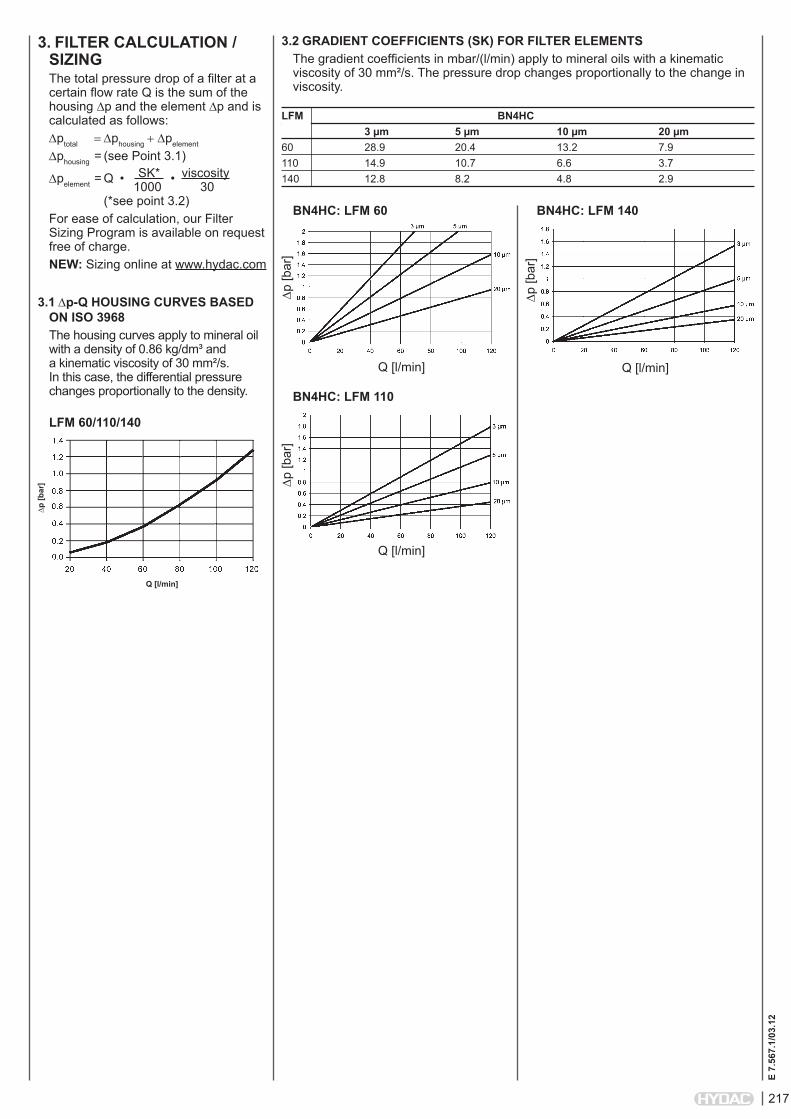
3. FiLTER CALCULATiON / SiZiNGThe total pressure drop of a filter at a certain flow rate Q is the sum of the housing ∆p and the element ∆p and is calculated as follows:∆ptotal =∆phousing+∆pelement
∆phousing = (see Point 3.1)
∆pelement = Q • SK* • viscosity 1000 30 (*see point 3.2)For ease of calculation, our Filter Sizing Program is available on request free of charge.NEW: Sizing online at www.hydac.com
3.1 ∆p-Q HOUSiNG CURVES BASED ON iSO 3968The housing curves apply to mineral oil with a density of 0.86 kg/dm³ and a kinematic viscosity of 30 mm²/s. In this case, the differential pressure changes proportionally to the density.
3.2 GRADiENT COEFFiCiENTS (SK) FOR FiLTER ELEMENTSThe gradient coefficients in mbar/(l/min) apply to mineral oils with a kinematic viscosity of 30 mm²/s. The pressure drop changes proportionally to the change in viscosity.
LFM 60/110/140
LFM BN4HC 3 µm 5 µm 10 µm 20 µm 60 28.9 20.4 13.2 7.9110 14.9 10.7 6.6 3.7140 12.8 8.2 4.8 2.9
∆p [b
ar]
Q [l/min]
BN4HC: LFM 60
∆p [b
ar]
BN4HC: LFM 110
∆p [b
ar]
Q [l/min]
BN4HC: LFM 140
∆p [b
ar]
Q [l/min]
Q [l/min]

218
E 7.
567.
1/03
.12
4. DiMENSiONS
NOTEThe information in this brochure relates to the operating conditions and applications described. For applications and operating conditions not described, please contact the relevant technical department. Subject to technical modifications.
HYDAC FiLTERTECHNiK GMBH Industriegebiet D-66280 Sulzbach/Saar, Germany Tel.: 0 68 97 / 509-01 Fax: 0 68 97 / 509-300 Internet: www.hydac.com E-mail: [email protected]
LFM Weight incl. Vol. of pressure element [kg] chamber [l]60 1.9 0.20110 2.3 0.33140 4.5 0.40
outlet G 3/4 x 16 deep
LFM
60
= 20
6.5
LFM
110
= 2
74.5
LF
M 1
40 =
318
.0inlet G 3/4 x 16 deep
tank connection M18 x 1.5 x 12 deepM6 x 9 deep
219
E 7.
556.
4/03
.12
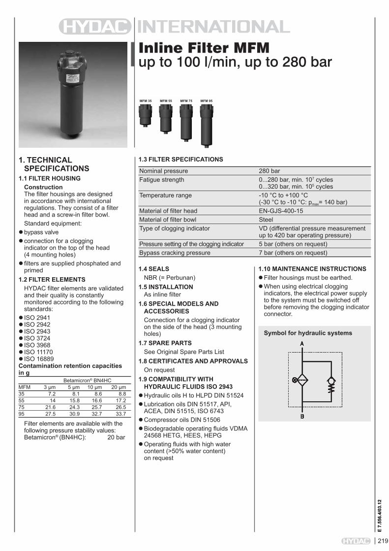
Inline Filter MFMup to 100 l/min, up to 280 bar
1. TECHNiCAL SPECiFiCATiONS
1.1 FiLTER HOUSiNGConstruction The filter housings are designed in accordance with international regulations. They consist of a filter head and a screw-in filter bowl.Standard equipment:
bypass valveconnection for a clogging
indicator on the top of the head (4 mounting holes)
filters are supplied phosphated and primed
1.2 FiLTER ELEMENTSHYDAC filter elements are validated and their quality is constantly monitored according to the following standards:
ISO 2941ISO 2942ISO 2943ISO 3724ISO 3968ISO 11170ISO 16889Contamination retention capacities in g Betamicron® BN4HCMFM 3 µm 5 µm 10 µm 20 µm35 7.2 8.1 8.6 8.855 14 15.8 16.6 17.275 21.6 24.3 25.7 26.595 27.5 30.9 32.7 33.7
Filter elements are available with the following pressure stability values:Betamicron® (BN4HC): 20 bar
1.4 SEALSNBR (= Perbunan)
1.5 iNSTALLATiON As inline filter
1.6 SPECiAL MODELS AND ACCESSORiESConnection for a clogging indicator on the side of the head (3 mounting holes)
1.7 SPARE PARTSSee Original Spare Parts List
1.8 CERTiFiCATES AND APPROVALSOn request
1.9 COMPATiBiLiTY WiTH HYDRAULiC FLUiDS iSO 2943
Hydraulic oils H to HLPD DIN 51524Lubrication oils DIN 51517, API,
ACEA, DIN 51515, ISO 6743Compressor oils DIN 51506Biodegradable operating fluids VDMA
24568 HETG, HEES, HEPGOperating fluids with high water
content (>50% water content) on request
1.10 MAiNTENANCE iNSTRUCTiONS Filter housings must be earthed.When using electrical clogging
indicators, the electrical power supply to the system must be switched off before removing the clogging indicator connector.
1.3 FiLTER SPECiFiCATiONS
Nominal pressure 280 bar Fatigue strength 0...280 bar, min. 107 cycles 0...320 bar, min. 105 cycles Temperature range -10 °C to +100 °C (-30 °C to -10 °C: pmax= 140 bar) Material of filter head EN-GJS-400-15 Material of filter bowl Steel Type of clogging indicator VD (differential pressure measurement up to 420 bar operating pressure) Pressure setting of the clogging indicator 5 bar (others on request) Bypass cracking pressure 7 bar (others on request)
Symbol for hydraulic systems
MFM 35 MFM 55 MFM 75 MFM 95
E 7.
556.
4/03
.12

220
E 7.
556.
4/03
.12
MFM BN/HC 55 O D 10 D 4 . X /-L24-B7
Filter type MFMFilter material BN/HC Betamicron® (BN4HC)Size of filter or element MFM: 35, 55, 75, 95Operating pressure O = 280 barType and size of connectionType Connection Filter size
35 55 75 95A M18 x 1.5 B G ½ E M22 x 1.5 H G ¾
Filtration rating in µm BN/HC: 3, 5, 10, 20Type of clogging indicator W without port (no clogging indicator) A plastic blanking plug in indicator port B visual for other clogging indicators, C electrical see brochure no. 7.050../.. D visual and electricalType code 3 clogging indicator port on side of head - 3 mounting holes 4 clogging indicator port on top of head - 4 mounting holesModification number X the latest version is always suppliedSupplementary details B7 standard: bypass cracking pressure 7 bar L... light with appropriate voltage (24, 48, 110, 220 Volt) only for clogging LED 2 light-emitting diodes up to 24 Volt indicators type "D" V FPM seals W suitable for HFA and HFC emulsions WAL right-angled bracket for side mounting, inlet on left (only possible for type code 4.x) WAR right-angled bracket for side mounting, inlet on right (only for type code 4.x)
2. MODEL CODE (also order example)2.1 COMPLETE FiLTER
0055 D 010 BN4HC /-V
Size 0035, 0055, 0075, 0095Type DFiltration rating in µm BN4HC: 003, 005, 010, 020Filter material BN4HCSupplementary details V (for descriptions, see point 2.1)
2.2 REPLACEMENT ELEMENT
2.3 REPLACEMENT CLOGGiNG iNDiCATOR VD 5 D . X /-L24
Type of indicator VD differential pressure indicator up to 450 bar operating pressurePressure setting 5 standard 5 bar, others on requestType of clogging indicator D (see point 2.1)Modification number X The latest version is always suppliedSupplementary details L..., LED, V, W (for descriptions, see point 2.1)

221
E 7.
556.
4/03
.12
3. FiLTER CALCULATiON / SiZiNGThe total pressure drop of a filter at a certain flow rate Q is the sum of the housing ∆p and the element ∆p and is calculated as follows:∆ptotal =∆phousing+∆pelement
∆phousing = (see Point 3.1)
∆pelement = Q • SK* • viscosity 1000 30 (*see Point 3.2)For ease of calculation, our Filter Sizing Program is available on request free of charge.NEW: Sizing online at www.hydac.com
3.1 ∆p-Q HOUSiNG CURVES BASED ON iSO 3968The housing curves apply to mineral oil with a density of 0.86 kg/dm³ and a kinematic viscosity of 30 mm²/s. In this case, the differential pressure changes proportionally to the density.
3.2 GRADiENT COEFFiCiENTS (SK) FOR FiLTER ELEMENTSThe gradient coefficients in mbar/(l/min) apply to mineral oils with a kinematic viscosity of 30 mm²/s. The pressure drop changes proportionally to the change in viscosity.
MFM - Port M18 x 1.5 / G ½
MFM BN4HC 3 µm 5 µm 10 µm 20 µm 35 23.6 19.0 14.8 9.355 13.7 11.0 8.1 4.875 9.3 7.5 5.3 3.195 7.5 6.0 4.1 2.4
∆p [b
ar]
Q [l/min]
BN4HC: MFM 35
∆p [b
ar]
BN4HC: MFM 55
∆p [b
ar]
Q [l/min]
BN4HC: MFM 75
∆p [b
ar]
Q [l/min]
MFM - Port M22 x 1.5 / G ¾
∆p [b
ar]
Q [l/min]
∆p [b
ar]
Q [l/min]
BN4HC: MFM 95
Q [l/min]

222
E 7.
556.
4/03
.12
4. DiMENSiONS
STANDARD VERSION 4.X SPECIAL VERSION 3.X
NOTEThe information in this brochure relates to the operating conditions and applications described. For applications or operating conditions not described, please contact the relevant technical department. Subject to technical modifications.
HYDAC FiLTERTECHNiK GMBH Industriegebiet D-66280 Sulzbach/Saar, Germany Tel.: 0 68 97 / 509-01 Fax: 0 68 97 / 509-300 Internet: www.hydac.com E-mail: [email protected]
MFM Weight incl. Vol. of pressure element [kg] chamber [l]35 3.7 0.2455 4.2 0.3975 4.7 0.5695 5.1 0.69
type code label attached M
FM 3
5 =
~158
Ø 34/1 deep
mounting thread M8 x 12/16 deep
MFM
55
= ~2
04
MFM
75
= ~2
57M
FM 9
5 =
~297
port
for c
logg
ing
indi
cato
r
port
for c
logg
ing
indi
cato
r
mounting thread M8 x 12/16 deep

227
E 7.
565.
1/03
.12
Pressure Filter DFM with Differential Pressure Relief Valveup to 280 l/min, up to 400 bar
1. TECHNiCAL SPECiFiCATiONS
1.1 FiLTER HOUSiNGConstruction The filter housings are designed in accordance with international regulations. They consist of a filter head and a screw-in filter bowl.Standard equipment:
differential pressure controlled relief valve
connection for a clogging indicator1.2 FiLTER ELEMENTS
HYDAC filter elements are validated and their quality is constantly monitored according to the following standards:
ISO 2941ISO 2942ISO 2943ISO 3724ISO 3968ISO 11170ISO 16889Contamination retention capacities in g Betamicron® BH4HCDFM 3 µm 5 µm 10 µm 20 µm160 12.9 12.6 13.9 15.9240 21.6 21.1 23.2 26.5280 48.1 47.1 51.8 59.1
Filter elements are available with the following pressure stability values:Betamicron® (BH4HC): 210 bar
1.4 SEALSNBR (= Perbunan)
1.5 iNSTALLATiON As inline filter
1.6 SPECiAL MODELS AND ACCESSORiESWith pressure release / oil drain plug (SO184)
1.7 SPARE PARTSSee Original Spare Parts List
1.8 CERTiFiCATES AND APPROVALSOn request
1.9 COMPATiBiLiTY WiTH HYDRAULiC FLUiDS iSO 2943
Hydraulic oils H to HLPD DIN 51524Lubrication oils DIN 51517, API,
ACEA, DIN 51515, ISO 6743Compressor oils DIN 51506Biodegradable operating fluids VDMA
24568 HETG, HEES, HEPGFire-resistant fluids HFA, HFB, HFC
and HFDOperating fluids with high water
content (>50% water content) on request
1.10 MAiNTENANCE iNSTRUCTiONS Filter housings must be earthed.When using electrical clogging
indicators, the electrical power supply to the system must be switched off before removing the clogging indicator connector.
1.3 FiLTER SPECiFiCATiONS
Nominal pressure 400 bar Fatigue strength At nominal pressure 106 cycles from 0 to nominal pressure Temperature range -30 °C to +100 °C (-30 °C to -10 °C: pmax= 200 bar) Material of filter head EN-GJS-400-15 Material of filter bowl Steel Type of clogging indicator VD (differential pressure measurement up to 420 bar operating pressure) Pressure setting of the clogging indicator 5 bar (others on request) Cracking pressure of differential 20 bar (others on request) pressure controlled relief valve NOTE: On request, BN4HC elements (pressure stability up to 20 bar) can also be used at lower cracking pressures.
Symbol for hydraulic systems
DFM 160 DFM 240 DFM 280
E 7.
565.
1/03
.12

228
E 7.
565.
1/03
.12
DFM BH/HC 240 S E 10 D 1 . X /-L24
Filter type DFMFilter material of element BH/HC Betamicron® (BH4HC)Size of filter or element DFM: 160, 240, 280Operating pressure S = 400 barType and size of connectionType Port Filter size
160 240 280E G1 ¼
Filtration rating in µm BH/HC : 3, 5, 10, 20Type of clogging indicator Y plastic blanking plug in indicator port A steel blanking plug in indicator port B visual for other clogging indicators, C electrical see brochure no. 7.050../.. D visual and electricalType code 1Modification number X the latest version is always suppliedSupplementary details L... light with appropriate voltage (24, 48, 110, 220 Volt) only for clogging LED 2 light-emitting diodes up to 24 Volt indicators type "D" SO184 pressure release/oil drain screw V FPM seals
2. MODEL CODE (also order example)2.1 COMPLETE FiLTER
0240 D 010 BH4HC /-V
Size 0160, 0240, 0280Type DFiltration rating in µm BH4HC: 003, 005, 010, 020Filter material BH4HCSupplementary details V (for descriptions, see point 2.1)
2.2 REPLACEMENT ELEMENT
2.3 REPLACEMENT CLOGGiNG iNDiCATOR VD 5 D . X /-L24
Type VD Diff. pressure indicator up to 420 bar oper. pressurePressure setting 5 standard 5 bar, others on requestType of clogging indicator D (see point 2.1)Modification number X the latest version is always suppliedSupplementary details L..., LED, V (for descriptions, see point 2.1)

229
E 7.
565.
1/03
.12
3. FiLTER CALCULATiON / SiZiNGThe total pressure drop of a filter at a certain flow rate Q is the sum of the housing ∆p and the element ∆p and is calculated as follows:∆ptotal =∆phousing+∆pelement
∆phousing = (see Point 3.1)
∆pelement = Q • SK* •viscosity 1000 30 (*see point 3.2) For ease of calculation, our Filter Sizing Program is available on request free of charge.NEW: Sizing online at www.hydac.com
3.1 ∆p-Q HOUSiNG CURVES BASED ON iSO 3968The housing curves apply to mineral oil with a density of 0.86 kg/dm³ and a kinematic viscosity of 30 mm²/s. In this case, the differential pressure changes proportionally to the density.
3.2 GRADiENT COEFFiCiENTS (SK) FOR FiLTER ELEMENTSThe gradient coefficients in mbar/(l/min) apply to mineral oils with a kinematic viscosity of 30 mm²/s. The pressure drop changes proportionally to the change in viscosity.
DFM 160/240/280
DFM BH4HC 3 µm 5 µm 10 µm 20 µm 160 16.8 10.4 5.9 4.4240 10.6 6.8 3.9 2.9280 5.7 3.4 1.8 1.6
∆p [b
ar]
Q [l/min]
BH4HC: DFM 160
∆p [b
ar]
BH4HC: DFM 240
∆p [b
ar]
Q [l/min]
BH4HC: DFM 280
Q [l/min]

230
E 7.
565.
1/03
.12
4. DiMENSiONS
NOTEThe information in this brochure relates to the operating conditions and applications described. For applications or operating conditions not described, please contact the relevant technical department. Subject to technical modifications.
HYDAC FiLTERTECHNiK GMBH Industriegebiet D-66280 Sulzbach/Saar, Germany Tel.: 0 68 97 / 509-01 Fax: 0 68 97 / 509-300 Internet: www.hydac.com E-mail: [email protected]
DFM Weight incl. element [kg]
Volume of pressure chamber [l]
160 11.0 0.6240 12.5 0.8280 17.1 1.45
hex SW32
DFM
160
: ~ 2
35
DFM
240
: ~ 2
91.5
DFM
280
: ~ 4
77
clogging indicator e.g. visual
filter inlet filter outlet
mounting 3x M8x14
tank

231
E 7.
569.
1/03
.12
Inline Filter ILF up to 120 l/min, up to 350 bar
1. TECHNiCAL SPECiFiCATiONS
1.1 FiLTER HOUSiNGConstruction The filter housings are designed in accordance with international regulations. They consist of a filter housing and a screw-in cover plate.Standard equipment:
without bypass valve (only ILF 1, ILF 3 and ILF 4)
with bypass valve (only ILF 2 and ILF 3)
1.2 FiLTER ELEMENTSHYDAC filter elements are validated and their quality is constantly monitored according to the following standards:
ISO 2941ISO 2942ISO 2943ISO 3724ISO 3968ISO 16889
Filter elements are available with the following pressure stability values:Betamicron® (BN4HC): 20 bar Betamicron® (BH4HC): 210 bar Wire mesh (W): up to 100 bar
1.4 SEALSPerbunan (= NBR)
1.5 iNSTALLATiON As inline filter
1.6 SPECiAL MODELS AND ACCESSORiES
bypass valve for ILF 3others on request
see original spare parts list1.7 SPARE PARTS
See Original Spare Parts List1.8 CERTiFiCATES AND APPROVALS
On request1.9 COMPATiBiLiTY WiTH
HYDRAULiC FLUiDS iSO 2943Hydraulic oils H to HLPD DIN 51524Lubrication oils DIN 51517, API,
ACEA, DIN 51515, ISO 6743Compressor oils DIN 51506Biodegradable operating fluids VDMA
24568 HETG, HEES, HEPGOperating fluids with high water
content (>50% water content) on request
1.10 MAiNTENANCE iNSTRUCTiONS Filter housings must be earthed.
1.3 FiLTER SPECiFiCATiONS
Nominal pressure ILF 1, 2, 3: 350 bar The permitted operating pressure will be reduced according to the max. permitted value of the threaded connection used! ILF 4: 160 bar Fatigue strength At nominal pressure 106 cycles from 0 to nominal pressure Temperature range -10 °C to +100 °C Material of filter housing and cover plate ILF 1, 2, 3: Steel 52-3 ILF 4: Aluminium Cracking pressure of bypass: ILF 2: 5.5 bar optional: ILF 3: 3 or 6 bar
Symbol for hydraulic systems
iLF 1 iLF 2
iLF 1
iLF 2
E 7.
569.
1/03
.12
iLF 3 iLF 4
iLF 3 and 4

232
E 7.
569.
1/03
.12
2.2 REPLACEMENT ELEMENT 1) HE03119932 100 -W /-VSize 0015 R2) only ILF 3 0015 D2) HE1468 only ILF 1 HE03119932 only ILF 2Filtration rating in µm BN4HC, BH4HC : 10, 20 (only ILF 3) W : 40, 100, 200 others on requestFilter material BN4HC, BH4HC, WSupplementary details B3 standard: bypass opening pressure for R elements B6 special bypass cracking pressure 6 bar (only for BN4HC elements) V (for descriptions, see Point 2.1)
1) Replacement element for ILF 4 on request! 2) Replacement element 0015 R... (bypass version) or 0015 D... (version without bypass)
NOTE: Same port size at inlet and outlet (for ILF 1 and 2) Please see Point 4 "Dimensions"!
2. MODEL CODE (also order example)2.1 COMPLETE FiLTER
NOTE: Same port size at inlet and outlet (for ILF 1 and 2) Please see Point 4 "Dimensions"!
X = only possible for female threads (Supplementary detail code: II)
X = only possible for female threads (Supplementary detail code: II)
iLF W 2 R F F 100 W 1 . X /-B5.5-iA
Filter type ILFFilter material of element W Wire mesh BN/HC Betamicron® (only ILF 3) BH/HC Betamicron® (only ILF 3)Size of filter or element ILF: 1, 2, 3, 4Operating pressure K = 160 bar (only ILF 4) R = 350 bar The permitted operating pressure will be reduced according to the max. permitted value of the threaded connection used!Type and size of port - inletType Port Filter size
1 2 3 4A M18x1.5 B G ½ XD M22x1.5 F M24x1.5 H M30x2 Type and size of port - outletType Port Filter size
1 2 3 4A M18x1.5 B G ½ XD M22x1.5 F M24x1.5 H M30x2 Filtration rating in µm BN/HC, BH/HC : 10, 20 (only ILF 3) W : 40, 801), 100, 200 others on requestType of clogging indicator W without port, no clogging indicatorType code 1 Modification number X the latest version is always suppliedSupplementary details B5.5 standard: bypass cracking pressure 5.5 bar = required info for iLF 22) B3 or B6 = required info for iLF 3 (if bypass valve is required!) V FPM sealsConnection type = Required info:inlet outlet CodeFemale Female IIFemale Male IAMale Female AIMale Male AA 1) Only for ILF 4 2) Not possible for ILF 1 and ILF 4

233
E 7.
569.
1/03
.12
4. DiMENSiONS
ILF 1
3. FiLTER CALCULATiON / SiZiNG
3.1 GRAPHS FOR COMPLETE FiLTERThe curves apply to mineral oil with a density of 0.86 kg/dm³ and a kinematic viscosity of 30mm²/s.
iLF 1
∆p [b
ar]
Q [l/min]
iLF 2
∆p [b
ar]
Q [l/min]
NF d1 d2 d3 d4 L1 L2 L3 L4 Weight incl. Vol. of pressure element [kg] chamber [l] 28 10 M18 M18 108 90 13.5 11 1.401 34 12 M22 M22 109 91 14,5 12 1.39 0.03 34 12 M24 M24 110 92 16.5 14 1.39
filter element HE 1468
Dire
ctio
n of
flow
iLF 3
∆p [b
ar]
Q [l/min]
iLF 4
∆p [b
ar]
Q [l/min]

234
E 7.
569.
1/03
.12
ILF 2
NF d1 d2 d3 d4 L1 L2 L3 L4 Weight incl. Vol. of pressure element [kg] chamber [l] 9 M18x1.5 M18x1.5 107 22 22 12 0.772 42 12 M22x1.5 M22x1.5 111 24 22 14 0.78 0.04 12 M24x1.5* M24x1.5* 111 24 22 14 0.79 12 M30x2 M30x2 115 26 24 16 0.83
dire
ctio
n of
flow
with
out b
ypas
sdirection of flow w
ith bypass
* Preferred types
235
E 7.
569.
1/03
.12
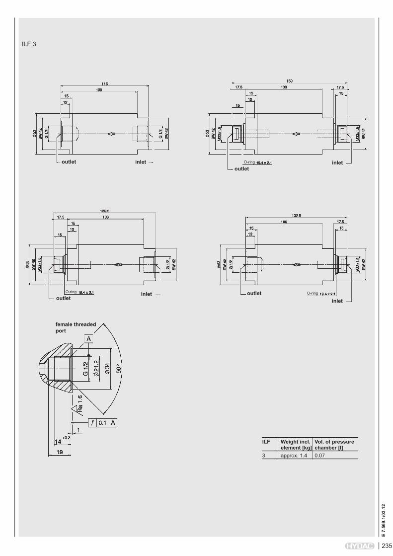
ILF 3
iLF Weight incl. Vol. of pressure element [kg] chamber [l]3 approx. 1.4 0.07
outlet inletoutlet
inletO-ring
outletinletO-ring outlet
inletO-ring
female threaded port

236
E 7.
569.
1/03
.12
NOTEThe information in this brochure relates to the operating conditions and applications described. For applications or operating conditions not described, please contact the relevant technical department. Subject to technical modifications.
HYDAC FiLTERTECHNik GMBH Industriegebiet 66280 Sulzbach/Saar, Germany Tel.: 0 68 97 / 509-01 Fax: 0 68 97 / 509-300 Internet: www.hydac.com E-mail: [email protected]
ILF 4
Outlet: M22x1.5
Inlet: M22x1.5

237
E 7.
566.
1/03
.12
Pressure Filter HFM up to 140 l/min, up to 400 bar
1. TECHNiCAL SPECiFiCATiONS
1.1 FiLTER HOUSiNGConstruction The filter housings are designed in accordance with international regulations. They consist of a filter head and a screw-in filter bowl.Standard equipment:
bypass valveconnection for a clogging
indicator on the top of the head (4 mounting holes)
1.2 FiLTER ELEMENTSHYDAC filter elements are validated and their quality is constantly monitored according to the following standards:
ISO 2941ISO 2942ISO 2943ISO 3724ISO 3968ISO 11170ISO 16889Contamination retention capacities in g Betamicron® BN4HCHFM 3 µm 5 µm 10 µm 20 µm75 21.6 24.3 25.7 26.595 27.5 30.9 32.7 33.7
Filter elements are available with the following pressure stability values:Betamicron® (BN4HC): 20 bar
1.4 SEALSNBR (= Perbunan)
1.5 iNSTALLATiON As inline filter
1.6 SPECiAL MODELS AND ACCESSORiESOn request
1.7 SPARE PARTSSee Original Spare Parts List
1.8 CERTiFiCATES AND APPROVALSOn request
1.9 COMPATiBiLiTY WiTH HYDRAULiC FLUiDS iSO 2943
Hydraulic oils H to HLPD DIN 51524Lubrication oils DIN 51517, API,
ACEA, DIN 51515, ISO 6743Compressor oils DIN 51506Biodegradable operating fluids VDMA
24568 HETG, HEES, HEPGOperating fluids with high water
content (>50% water content) on request
1.10 MAiNTENANCE iNSTRUCTiONS Filter housings must be earthed.When using electrical clogging
indicators, the electrical power supply to the system must be switched off before removing the clogging indicator connector.
1.3 FiLTER SPECiFiCATiONS
Nominal pressure 400 bar Fatigue strength At nominal pressure 106 cycles from 0 to nominal pressure Temperature range -10 °C to +100 °C (-30 °C to -10 °C: pmax= 200 bar) Material of filter head EN-GJS 400-15 Material of filter bowl Cold extruded steel Type of clogging indicator VD (differential pressure measurement up to 420 bar operating pressure) Pressure setting of the clogging indicator 5 bar (others on request) Bypass cracking pressure 7 bar (others on request)
Symbol for hydraulic systems
HFM 75 HFM 95
E 7.
566.
1/03
.12

238
E 7.
566.
1/03
.12
HFM BN/HC 75 S J 10 D 1 . X /-L24
Filter type HFMFilter material of element BN/HC Betamicron® (BN4HC)Size of filter or element HFM: 75, 95Operating pressure S = 400 barType and size of connectionType Port Filter size
75 95H G ¾ J G 1
Filtration rating in µm BN/HC: 3, 5, 10, 20Type of clogging indicator W without port (no clogging indicator) A plastic blanking plug in indicator port B visual for other clogging indicators, C electrical see brochure no. 7.050../.. D visual and electricalType code 1 Modification number X the latest version is always suppliedSupplementary details B7 standard: bypass cracking pressure 7 bar L... light with appropriate voltage (24, 48, 110, 220 Volt) only for clogging LED 2 light-emitting diodes up to 24 Volt indicators type "D" V FPM seals W suitable for HFA and HFC emulsions
2. MODEL CODE (also order example)2.1 COMPLETE FiLTER
0075 D 010 BN4HC /-V
Size 0075, 0095Type DFiltration rating in µm BN4HC: 003, 005, 010, 020Filter material BN4HCSupplementary details V (for descriptions, see point 2.1)
2.2 REPLACEMENT ELEMENT
2.3 REPLACEMENT CLOGGiNG iNDiCATOR VD 5 D . X /-L24
Type VD differential pressure indicator up to 420 bar operating pressurePressure setting 5 standard 5 bar, others on requestType of clogging indicator D (see point 2.1)Modification number X the latest version is always suppliedSupplementary details L..., LED, V, W (for descriptions, see point 2.1)

239
E 7.
566.
1/03
.12
3. FiLTER CALCULATiON / SiZiNGThe total pressure drop of a filter at a certain flow rate Q is the sum of the housing ∆p and the element ∆p and is calculated as follows:∆ptotal =∆phousing+∆pelement
∆phousing = (see Point 3.1)
∆pelement = Q • SK* •viscosity 1000 30 (*see Point 3.2)For ease of calculation, our Filter Sizing Program is available on request free of charge.NEW: Sizing online at www.hydac.com
3.1 ∆p-Q HOUSiNG CURVES BASED ON iSO 3968The housing curves apply to mineral oil with a density of 0.86 kg/dm³ and a kinematic viscosity of 30 mm²/s. In this case, the differential pressure changes proportionally to the density.
3.2 GRADiENT COEFFiCiENTS (SK) FOR FiLTER ELEMENTSThe gradient coefficients in mbar/(l/min) apply to mineral oils with a kinematic viscosity of 30 mm²/s. The pressure drop changes proportionally to the change in viscosity.
HFM
HFM BN4HC 3 µm 5 µm 10 µm 20 µm75 9.3 7.5 5.3 3.195 7.5 6.0 4.1 2.4
∆p [b
ar]
Q [l/min]
BN4HC: HFM 75
∆p [b
ar]
Q [l/min]
BN4HC: HFM 95
∆p [b
ar]
Q [l/min]

240
E 7.
566.
1/03
.12
4. DiMENSiONS
NOTEThe information in this brochure relates to the operating conditions and applications described. For applications or operating conditions not described, please contact the relevant technical department. Subject to technical modifications.
HYDAC FiLTERTECHNiK GMBH Industriegebiet D-66280 Sulzbach/Saar, Germany Tel.: 0 68 97 / 509-01 Fax: 0 68 97 / 509-300 Internet: www.hydac.com E-mail: [email protected]
mounting thread M6
HFM
95:
HFM
75:
mounting thread M8
connection for clogging indicator
HFM Weight incl. Vol. of pressure element [kg] chamber [l]75 5.6 0.5695 6.1 0.69