spin-on filters introduction - stauff one/noam-version... · spin-on filters technical data /...
TRANSCRIPT
C132 www.stauff.com
Spin-On Filters Technical Data
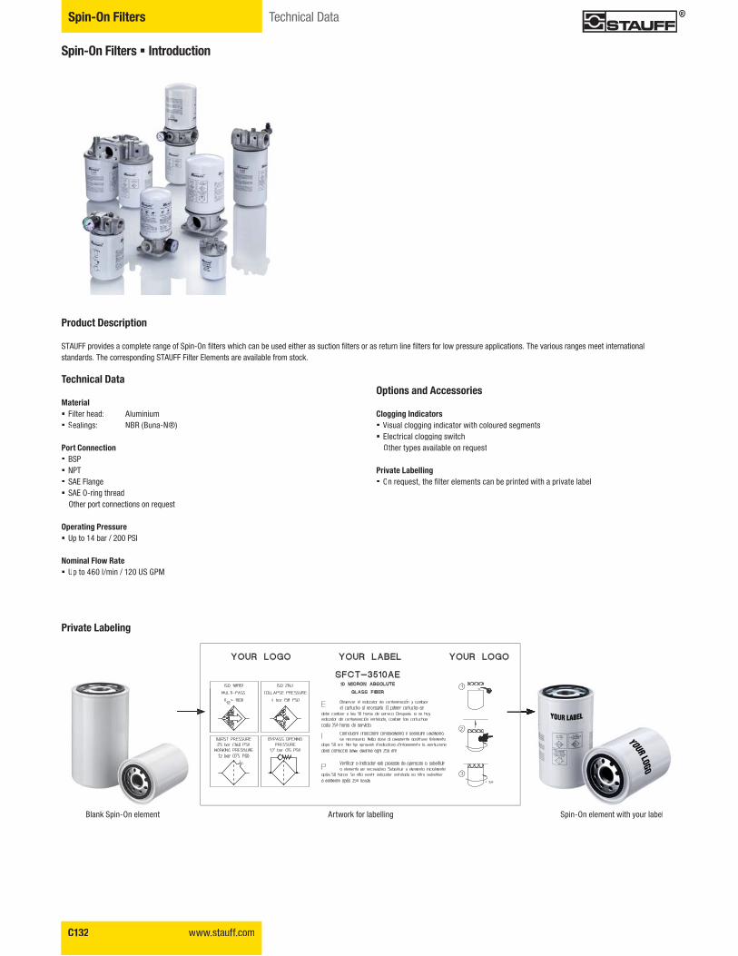
Blank Spin-On element Artwork for labelling Spin-On element with your labelS i O l t ith l b l
Spin-On Filters � Introduction
Product Description STAUFF provides a complete range of Spin-On filters which can be used either as suction filters or as return line filters for low pressure applications. The various ranges meet international standards. The corresponding STAUFF Filter Elements are available from stock.
Technical Data
Material � Filter head: Aluminium � Sealings: NBR (Buna-N®)
Port Connection� BSP� NPT� SAE Flange� SAE O-ring thread Other port connections on request
Operating Pressure� Up to 14 bar / 200 PSI
Nominal Flow Rate � Up to 460 l/min / 120 US GPM
Options and Accessories
Clogging Indicators � Visual clogging indicator with coloured segments� Electrical clogging switch
Other types available on request
Private Labelling � ������������� �������������������������������������������
Private Labeling
www.stauff.com C133
Filtr
atio
nTe
chno
logy
C
Spin-On FiltersTechnical Data
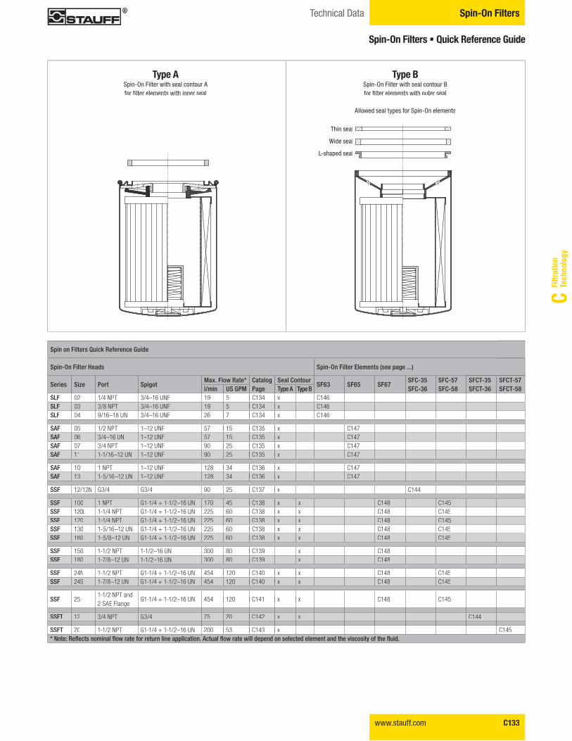
Type ASpin-On Filter with seal contour A ���� ������������������������
Spin on Filters Quick Reference Guide
Spin-On Filter Heads Spin-On Filter Elements (see page ...)
Series Size Port SpigotMax. Flow Rate* Catalog
PageSeal Contour
SF63 SF65 SF67SFC-35SFC-36
SFC-57SFC-58
SFCT-35SFCT-36
SFCT-57SFCT-58l/min US GPM Type A Type B
SLF 02 1/4 NPT 3/4–16 UNF 19 5 C134 x C146SLF 03 3/8 NPT 3/4–16 UNF 19 5 C134 x C146SLF 04 9/16–18 UN 3/4–16 UNF 26 7 C134 x C146
SAF 05 1/2 NPT 1–12 UNF 57 15 C135 x C147SAF 06 3/4–16 UN 1–12 UNF 57 15 C135 x C147SAF 07 3/4 NPT 1–12 UNF 90 25 C135 x C147SAF 11 1-1/16–12 UN 1–12 UNF 90 25 C135 x C147
SAF 10 1 NPT 1–12 UNF 128 34 C136 x C147SAF 13 1-5/16–12 UN 1–12 UNF 128 34 C136 x C147
SSF 12/12N G3/4 G3/4 90 25 C137 x C144
SSF 100 1 NPT G1-1/4 + 1-1/2–16 UN 170 45 C138 x x C148 C145SSF 120L 1-1/4 NPT G1-1/4 + 1-1/2–16 UN 225 60 C138 x x C148 C145SSF 120 1-1/4 NPT G1-1/4 + 1-1/2–16 UN 225 60 C138 x x C148 C145SSF 130 1-5/16–12 UN G1-1/4 + 1-1/2–16 UN 225 60 C138 x x C148 C145SSF 160 1-5/8–12 UN G1-1/4 + 1-1/2–16 UN 225 60 C138 x x C148 C145
SSF 150 1-1/2 NPT 1-1/2–16 UN 300 80 C139 x C148SSF 180 1-7/8–12 UN 1-1/2–16 UN 300 80 C139 x C148
SSF 24N 1-1/2 NPT G1-1/4 + 1-1/2–16 UN 454 120 C140 x x C148 C145SSF 24S 1-7/8–12 UN G1-1/4 + 1-1/2–16 UN 454 120 C140 x x C148 C145
SSF 251-1/2 NPT and 2 SAE Flange
G1-1/4 + 1-1/2–16 UN 454 120 C141 x x C148 C145
SSFT 12 3/4 NPT G3/4 75 20 C142 x x C144
SSFT 20 1-1/2 NPT G1-1/4 + 1-1/2–16 UN 200 53 C143 x C145�������������� ��� �������������������� ��� ������������ �������������������������� ��� ��������������� ��� ���������������������������
Spin-On Filters � Quick Reference Guide
Type BSpin-On Filter with seal contour B���� ������������������������
Allowed seal types for Spin-On elements
Thin seal
Wide seal
L-shaped seal
C134 www.stauff.com
Spin-On Filters Technical Data / Dimensions / Order Code
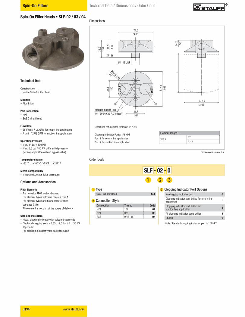
Spin-On Filter Heads � SLF-02 / 03 / 04
Technical Data
Construction � ���������������� ��������
Material � Aluminium
Port Connection� NPT� SAE O-ring thread
Flow Rate � 26 l/min / 7 US GPM for return line application� 7 l/min / 2 US GPM for suction line application
Operating Pressure � Max. 14 bar / 200 PSI � Max. 5,5 bar / 80 PSI differential pressure
(for any applicaton with no bypass valve)
Temperature Range � -32°C ... +100°C / -25°F ... +212°F
Media Compatibility � �������������������������������
Options and Accessories
Filter Elements � For use with SF63 series elements
For element types with seal contour type A�����������!�����������������������see page C146The element is not part of the scope of delivery
Clogging Indicators � Visual clogging indicator with coloured segments� Electrical clogging switch 0,35 ... 2,5 bar / 5 ... 35 PSI
adjustableFor clogging indicator types see page C152
Order Code
����� ���� �����
SF6387
3.43
� Type Spin-On Filter Head SLF
� Connection Style
SLF - 02 - 0
� Clogging Indicator Port Options
Note: Standard clogging indicator port is 1/8 NPT.
Connection !����� CodeNPT 1/4 02NPT 3/8 03SAE 9/16–18 04
No clogging indicator port 0
Clogging indicator port drilled for return line application 1
Clogging indicator port drilled for suction line application 2
All clogging indicator ports drilled 4
Special 9
Dimensions
3/4–16 UNF
Mounting holes (2x)1/4–20 UNC (9 / .38 deep)
Clearance for element removal: 15 / .59
Clogging Indicator Ports: 1/8 NPTPos. 1 for return line applicationPos. 2 for suction line application
TLO
UTLTL
ETTL
INLE
TLE
TIN
LIN
LET
77,53.05
Ø77,53.05
41,71.64
14,2
.56
28,5
1.12
10 .39
38,5
1.52
38,1
1.50
Ø24,9 (2X)
.98
L
Dimensions in mm / in
Ø77,
53.
05
www.stauff.com C135
Filtr
atio
nTe
chno
logy
C
Spin-On FiltersTechnical Data / Dimensions / Order Code
����� ���� �����
L1 SF65 short elements147
5.76
L2 SF65 long elements204
8
� Clogging Indicator Port Options
Note: Standard clogging indicator port is 1/8 NPT.
No clogging indicator port 0
Clogging indicator port drilled for return line application 1
Clogging indicator port drilled forsuction line application 2
All clogging indicator ports drilled 4
Special 9
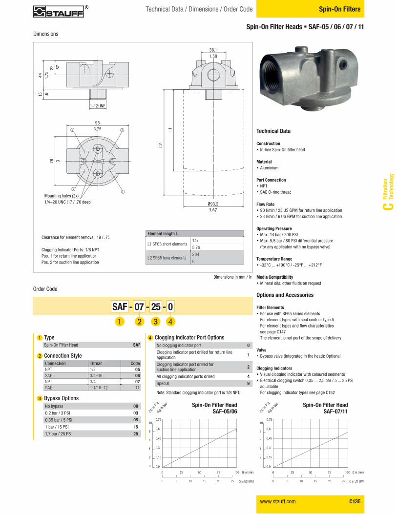
Mounting holes (2x)1/4–20 UNC (17 / .70 deep)
Clearance for element removal: 19 / .75
Clogging Indicator Ports: 1/8 NPTPos. 1 for return line applicationPos. 2 for suction line application
Spin-On Filter Heads � SAF-05 / 06 / 07 / 11
Technical Data
Construction � ���������������� ���������
Material � Aluminium
Port Connection� NPT� SAE O-ring thread
Flow Rate � 90 l/min / 25 US GPM for return line application� 23 l/min / 6 US GPM for suction line application
Operating Pressure � Max. 14 bar / 200 PSI � Max. 5,5 bar / 80 PSI differential pressure
(for any applicaton with no bypass valve)
Temperature Range � -32°C ... +100°C / -25°F ... +212°F
Media Compatibility � ��������������������������������
Options and Accessories
Filter Elements � For use with SF65 series elements
For element types with seal contour type A�����������!������������������������see page C147The element is not part of the scope of delivery
Valve � Bypass valve (integrated in the head): Optional
Clogging Indicators � Visual clogging indicator with coloured segments� Electrical clogging switch 0,35 ... 2,5 bar / 5 ... 35 PSI
adjustableFor clogging indicator types see page C152
Order Code
Dimensions
Dimensions in mm / in
SAF - 07 - 25 - 0
� Type Spin-On Filter Head SAF
� Connection Style
� Bypass Options
Connection !����� CodeNPT 1/2 05SAE 3/4–16 06NPT 3/4 07SAE 1-1/16–12 11
No bypass 00
0,2 bar / 3 PSI 03
0,35 bar / 5 PSI 05
1 bar / 15 PSI 15
1,7 bar / 25 PSI 25
1–12 UNF
38,11.50
953.75
Ø93,23.67
22 .87
L1
44 1.75
76 3
15 .6
L2
Spin-On Filter HeadSAF-05/06
Spin-On Filter HeadSAF-07/11
0,75
0,6
0,45
0,3
0,15
0,0
0,75
0,6
0,45
0,3
0,15
0,0
10
8
6
4
2
0
10
8
6
4
2
0
"p in b
ar
�p in P
SI
"p in b
ar
�p in P
SI
Q in l/min
Q in US GPM
Q in l/min
Q in US GPM
0 25 50 75 100 0 25 50 75 100
0 5 10 15 20 25 0 5 10 15 20 25
C136 www.stauff.com
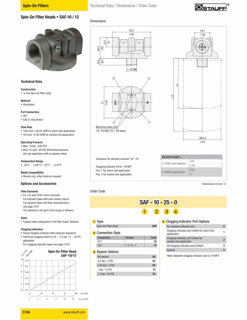
Spin-On Filter Heads � SAF-10 / 13
Technical Data
Construction � ���������������� ��������
Material � Aluminium
Port Connection� NPT� SAE O-ring thread
Flow Rate � 128 l/min / 34 US GPM for return line application� 30 l/min / 8 US GPM for suction line application
Operating Pressure� Max. 14 bar / 200 PSI� Max. 5,5 bar / 80 PSI differential pressure
(for any applicaton with no bypass valve)
Temperature Range � -32°C ... +100°C / -25°F ... +212°F
Media Compatibility � �������������������������������
Options and Accessories
Filter Elements � For use with SF65 series elements
For element types with seal contour type A�����������!�����������������������see page C147The element is not part of the scope of delivery
Valve � #!���������$���%����������� ��������&'��������
Clogging Indicators � Visual clogging indicator with coloured segments� Electrical clogging switch 0,35 ... 2,5 bar / 5 ... 35 PSI
adjustableFor clogging indicator types see page C152
Dimensions
Dimensions in mm / in
Order Code
SAF - 10 - 25 - 0
� Type Spin-On Filter Head SAF
� Connection Style
� Bypass Options
Connection !����� CodeNPT 1 10SAE 1-5/16–12 13
No bypass 00
0,2 bar / 3 PSI 03
0,35 bar / 5 PSI 05
1 bar / 15 PSI 15
1,7 bar / 25 PSI 25
1–12 UNFF
OUT
IN
38,11.50
92,73.65
Ø93,23.67
L1
23,1
.91
L2
46,5
1.83
16,5
.65
77 3.03
����� ���� �����
L1 SF65 short element147
5.76
L2 SF65 long element204
8
Mounting holes (2x))1/4–20 UNC (23 / .94 deep)
Clearance for element removal: 19 / .75
Clogging Indicator Ports: 1/8 NPTPos. 1 for return line applicationPos. 2 for suction line application
� Clogging Indicator Port Options
Note: Standard clogging indicator port is 1/8 NPT.
No clogging indicator port 0
Clogging indicator port drilled for return line application 1
Clogging indicator port drilled forsuction line application 2
All clogging indicator ports drilled 4
Special 9Spin-On Filter HeadSAF-10/13
0,75
0,6
0,45
0,3
0,15
0,0
10
8
6
4
2
0
"p in b
ar
�p in P
SI
Q in l/min
Q in US GPM
0 25 50 75 100
0 5 10 15 20 25
Spin-On Filters Technical Data / Dimensions / Order Code
www.stauff.com C137
Filtr
atio
nTe
chno
logy
C
953.74
G3/4
19,5.77
Ø983.86
43 1.69
20 .79
58,5
2.30
38 1.49
L2
L1
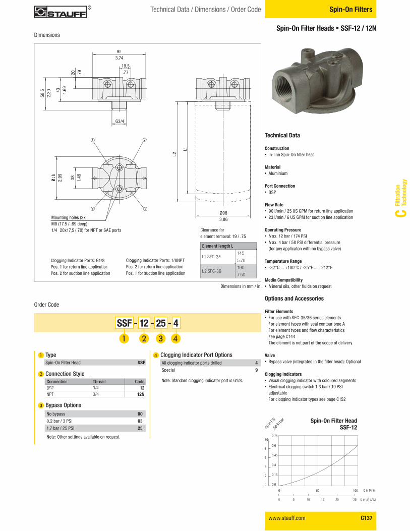
Spin-On Filter Heads � SSF-12 / 12N
Technical Data
Construction � ���������������� ��������
Material � Aluminium
Port Connection� BSP
Flow Rate � 90 l/min / 25 US GPM for return line application� 23 l/min / 6 US GPM for suction line application
Operating Pressure � Max. 12 bar / 174 PSI� Max. 4 bar / 58 PSI differential pressure
(for any applicaton with no bypass valve)
Temperature Range � -32°C ... +100°C / -25°F ... +212°F
Media Compatibility � �������������������������������
Options and Accessories
Filter Elements � For use with SFC-35/36 series elements
For element types with seal contour type A�����������!�����������������������see page C144The element is not part of the scope of delivery
Valve � #!���������$���%����������� ��������&'��������
Clogging Indicators � Visual clogging indicator with coloured segments� Electrical clogging switch 1,3 bar / 19 PSI
adjustableFor clogging indicator types see page C152
Dimensions
Order Code
SSF - 12 - 25 - 4
� Type Spin-On Filter Head SSF
� Connection Style
� Bypass Options
Connection !����� CodeBSP 3/4 12NPT 3/4 12N
No bypass 00
0,2 bar / 3 PSI 03
1,7 bar / 25 PSI 25
� Clogging Indicator Port Options
Note: Standard clogging indicator port is G1/8.
All clogging indicator ports drilled 4
Special 9
Dimensions in mm / in
����� ���� �����
L1 SFC-35145
5.70
L2 SFC-36190
7.50
Mounting holes (2x)M8 (17.5 / .69 deep)1/4–20x17,5 (.70) for NPT or SAE ports Clearance for
element removal: 19 / .75
Spin-On Filter HeadSSF-12
0,75
0,6
0,45
0,3
0,15
0,0
10
8
6
4
2
0
"p in b
ar
�p in P
SI
Q in l/min
Q in US GPM
0 50 100
0 5 10 15 20 25
2.99
Note: Other settings available on request.
Spin-On FiltersTechnical Data / Dimensions / Order Code
Clogging Indicator Ports: G1/8Pos. 1 for return line applicationPos. 2 for suction line application
Clogging Indicator Ports: 1/8NPTPos. 2 for return line applicationPos. 1 for suction line application
C138 www.stauff.com
Spin-On Filters Technical Data / Dimensions / Order Code
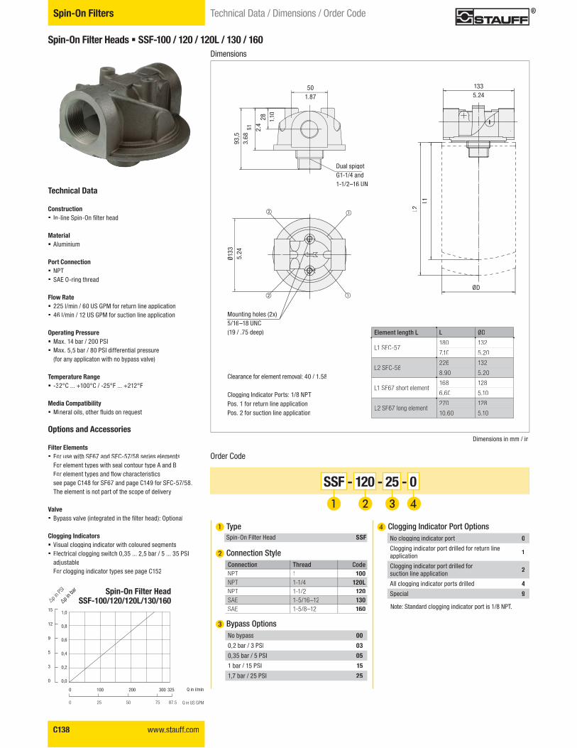
� Clogging Indicator Port Options
Note: Standard clogging indicator port is 1/8 NPT.
No clogging indicator port 0
Clogging indicator port drilled for return lineapplication 1
Clogging indicator port drilled for suction line application 2
All clogging indicator ports drilled 4
Special 9
Spin-On Filter Heads � SSF-100 / 120 / 120L / 130 / 160
Technical Data
Construction � ���������������� ��������
Material � Aluminium
Port Connection� NPT� SAE O-ring thread
Flow Rate � 225 l/min / 60 US GPM for return line application� 46 l/min / 12 US GPM for suction line application
Operating Pressure� Max. 14 bar / 200 PSI � Max. 5,5 bar / 80 PSI differential pressure
(for any applicaton with no bypass valve)
Temperature Range � -32°C ... +100°C / -25°F ... +212°F
Media Compatibility � �������������������������������
Options and Accessories
Filter Elements � For use with SF67 and SFC-57/58 series elements
For element types with seal contour type A and B �����������!�����������������������see page C148 for SF67 and page C149 for SFC-57/58.
The element is not part of the scope of delivery
Valve � #!���������$���%����������� ��������&'��������
Clogging Indicators � Visual clogging indicator with coloured segments� Electrical clogging switch 0,35 ... 2,5 bar / 5 ... 35 PSI
adjustableFor clogging indicator types see page C152
Dimensions
Dimensions in mm / in
Order Code
SSF - 120 - 25 - 0
� Type Spin-On Filter Head SSF
� Connection Style
� Bypass Options
Connection !����� CodeNPT 1 100NPT 1-1/4 120LNPT 1-1/2 120SAE 1-5/16–12 130SAE 1-5/8–12 160
No bypass 00
0,2 bar / 3 PSI 03
0,35 bar / 5 PSI 05
1 bar / 15 PSI 15
1,7 bar / 25 PSI 25
501.87
1335.24
ØD
L2
L1
28 1.10
61 2.4
93,5
3.68
Dual spigotG1-1/4 and 1-1/2–16 UN
Clearance for element removal: 40 / 1.58
Clogging Indicator Ports: 1/8 NPTPos. 1 for return line applicationPos. 2 for suction line application
Mounting holes (2x)5/16–18 UNC (19 / .75 deep)
Spin-On Filter HeadSSF-100/120/120L/130/160
1,0
0,8
0,6
0,4
0,2
0,0
15
12
9
5
3
0
"p in b
ar
�p in P
SI
Q in l/min
Q in US GPM
0 100 200 300 325
0 25 50 75 87.5
Ø133
5.24
����� ���� ����� L ØD
L1 SFC-57180 132
7.10 5.20
L2 SFC-58226 132
8.90 5.20
L1 SF67 short element168 128
6.60 5.10
L2 SF67 long element270 128
10.60 5.10
www.stauff.com C139
Filtr
atio
nTe
chno
logy
C
Spin-On FiltersTechnical Data / Dimensions / Order Code
Order Code
Dimensions in mm / in
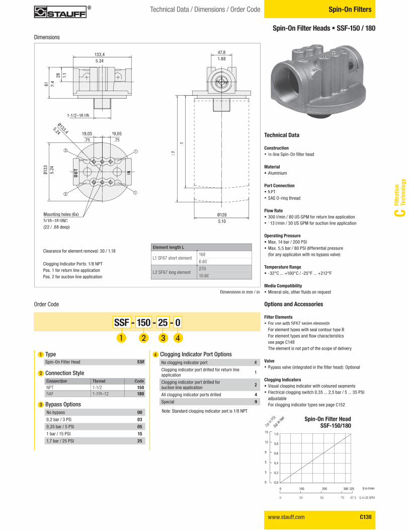
SSF - 150 - 25 - 0
� Type Spin-On Filter Head SSF
� Connection Style
� Bypass Options
Connection !����� CodeNPT 1-1/2 150SAE 1-7/8–12 180
No bypass 00
0,2 bar / 3 PSI 03
0,35 bar / 5 PSI 05
1 bar / 15 PSI 15
1,7 bar / 25 PSI 25
47,81.88
1-1/2–16 UN
19,05.75
19,05.75
28 1.1
133,45.24
61 2.4
L2
L1
OU
T
IN
Ø133,4
5.24
����� ���� �����
L1 SF67 short element168
6.60
L2 SF67 long element270
10.60
Clearance for element removal: 30 / 1.18
Clogging Indicator Ports: 1/8 NPTPos. 1 for return line applicationPos. 2 for suction line application
Mounting holes (6x)5/16–18 UNC (22 / .88 deep)
� Clogging Indicator Port Options
Note: Standard clogging indicator port is 1/8 NPT.
No clogging indicator port 0
Clogging indicator port drilled for return lineapplication 1
Clogging indicator port drilled forsuction line application 2
All clogging indicator ports drilled 4
Special 9
Ø1285.10
Ø133
5.24
Spin-On Filter Heads � SSF-150 / 180
Technical Data
Construction � ���������������� ��������
Material � Aluminium
Port Connection� NPT� SAE O-ring thread
Flow Rate � 300 l/min / 80 US GPM for return line application� 113 l/min / 30 US GPM for suction line application
Operating Pressure � Max. 14 bar / 200 PSI� Max. 5,5 bar / 80 PSI differential pressure
(for any applicaton with no bypass valve)
Temperature Range � -32°C ... +100°C / -25°F ... +212°F
Media Compatibility � �������������������������������
Options and Accessories
Filter Elements � For use with SF67 series elements
For element types with seal contour type B�����������!����������������������see page C148
The element is not part of the scope of delivery
Valve � #!���������$���%����������� ��������&'��������
Clogging Indicators � Visual clogging indicator with coloured segments� Electrical clogging switch 0,35 ... 2,5 bar / 5 ... 35 PSI
adjustableFor clogging indicator types see page C152
Spin-On Filter HeadSSF-150/180
1,0
0,8
0,6
0,4
0,2
0,0
15
12
9
5
3
0
"p in b
ar
�p in P
SI
0 100 200 300 325
0 25 50 75 87.5
Dimensions
Q in l/min
Q in US GPM
C140 www.stauff.com
Spin-On Filters Technical Data / Dimensions / Order Code
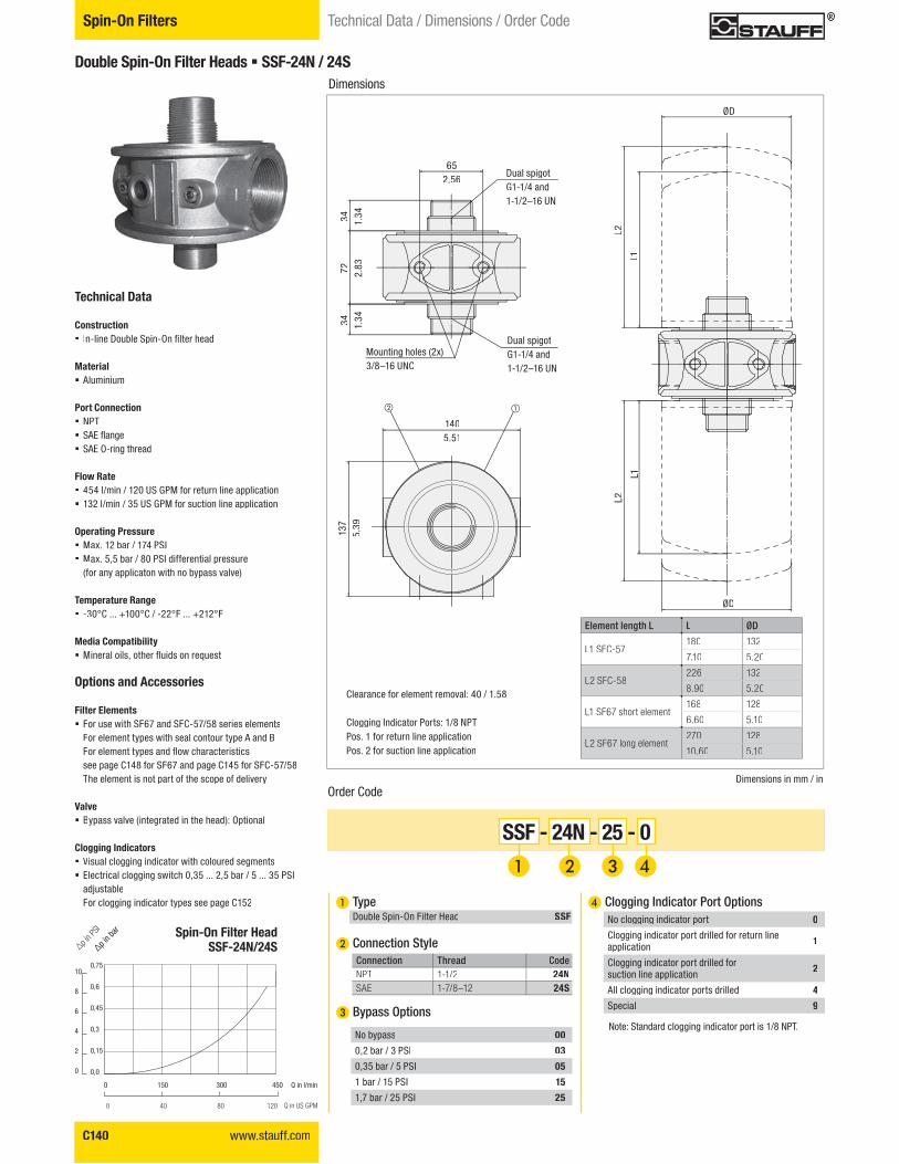
Double Spin-On Filter Heads � SSF-24N / 24S
Technical Data
Construction � ��������*�������������� ��������
Material � Aluminium
Port Connection� NPT � SAE flange� SAE O-ring thread
Flow Rate � 454 l/min / 120 US GPM for return line application� 132 l/min / 35 US GPM for suction line application
Operating Pressure� Max. 12 bar / 174 PSI � Max. 5,5 bar / 80 PSI differential pressure
(for any applicaton with no bypass valve)
Temperature Range � -30°C ... +100°C / -22°F ... +212°F
Media Compatibility � �������������������������������
Options and Accessories
Filter Elements � For use with SF67 and SFC-57/58 series elements
For element types with seal contour type A and B�����������!�����������������������see page C148 for SF67 and page C145 for SFC-57/58The element is not part of the scope of delivery
Valve � Bypass valve (integrated in the head): Optional
Clogging Indicators � Visual clogging indicator with coloured segments� Electrical clogging switch 0,35 ... 2,5 bar / 5 ... 35 PSI
adjustableFor clogging indicator types see page C152
Dimensions
Dimensions in mm / in
ØD
ØD
1405.51
652.56
L1L1
34 1.34
137
5.39
72 2.83
34 1.34
L2L2
����� ���� ����� L ØD
L1 SFC-57180 132
7.10 5.20
L2 SFC-58226 132
8.90 5.20
L1 SF67 short element168 128
6.60 5.10
L2 SF67 long element270 128
10.60 5.10
Order Code
SSF - 24N - 25 - 0
� Type Double Spin-On Filter Head SSF
� Connection Style
� Bypass Options
Connection !����� CodeNPT 1-1/2 24NSAE 1-7/8–12 24S
No bypass 00
0,2 bar / 3 PSI 03
0,35 bar / 5 PSI 05
1 bar / 15 PSI 15
1,7 bar / 25 PSI 25
Clearance for element removal: 40 / 1.58
Clogging Indicator Ports: 1/8 NPTPos. 1 for return line applicationPos. 2 for suction line application
Dual spigotG1-1/4 and1-1/2–16 UN
Dual spigotG1-1/4 and 1-1/2–16 UN
Mounting holes (2x)3/8–16 UNC
� Clogging Indicator Port Options
Note: Standard clogging indicator port is 1/8 NPT.
No clogging indicator port 0
Clogging indicator port drilled for return lineapplication 1
Clogging indicator port drilled for suction line application 2
All clogging indicator ports drilled 4
Special 9
Spin-On Filter HeadSSF-24N/24S
0,75
0,6
0,45
0,3
0,15
0,0
10
8
6
4
2
0
"p in b
ar
�p in P
SI
Q in l/min
Q in US GPM
0 150 300 450
0 40 80 120
www.stauff.com C141
Filtr
atio
nTe
chno
logy
C
Spin-On FiltersTechnical Data / Dimensions / Order Code
Dimensions
Order Code
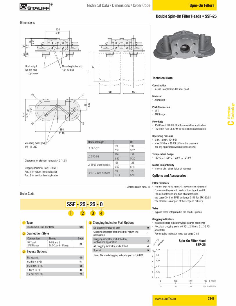
SSF - 25 - 25 - 0
� Type Double Spin-On Filter Head SSF
� Connection Style
� Bypass Options
Connection !����� CodeNPT and SAE Flange
1-1/2 and 2 SAE Code 61 Flange 25
No bypass 00
0,2 bar / 3 PSI 03
0,35 bar / 5 PSI 05
1 bar / 15 PSI 15
1,7 bar / 25 PSI 25
Dimensions in mm / in
ØDØD
Dual spigotG1-1/4 and1-1/2–16 UN
Mounting holes (4x)1/2–13 UNC
Mounting holes (3x) 3/8–16 UNC
28411.18
1505.91
36 1.42
84 3.31
32 1.26
60 2.36
56 2.20
L1
L2
134
5.28
����� ���� ����� L ØD
L1 SFC-57180 132
7.10 5.20
L2 SFC-58226 132
8.90 5.20
L1 SF67 short element168 128
6.60 5.10
L2 SF67 long element270 128
10.60 5.10
Clearance for element removal: 40 / 1.58
Clogging Indicator Port: 1/8 NPTPos. 1 for return line applicationPos. 2 for suction line application
� Clogging Indicator Port Options
Note: Standard clogging indicator port is 1/8 NPT.
No clogging indicator port 0
Clogging indicator port drilled for return lineapplication 1
Clogging indicator port drilled forsuction line application 2
All clogging indicator ports drilled 4
Special 9
Double Spin-On Filter Heads � SSF-25
Technical Data
Construction � ��������*�������������� ��������
Material � Aluminium
Port Connection� NPT � SAE flange
Flow Rate � 454 l/min / 120 US GPM for return line application� 132 l/min / 35 US GPM for suction line application
Operating Pressure� Max. 12 bar / 174 PSI� Max. 5,5 bar / 80 PSI differential pressure
(for any applicaton with no bypass valve)
Temperature Range � -30°C ... +100°C / -22°F ... +212°F
Media Compatibility � �������������������������������
Options and Accessories
Filter Elements � For use with SF67 and SFC-57/58 series elements
For element types with seal contour type A and B�����������!�����������������������see page C148 for SF67 and page C145 for SFC-57/58The element is not part of the scope of delivery
Valve � Bypass valve (integrated in the head): Optional
Clogging Indicators � Visual clogging indicator with coloured segments� Electrical clogging switch 0,35 ... 2,5 bar / 5 ... 35 PSI
adjustableFor clogging indicator types see page C152
Spin-On Filter HeadSSF-25
0,75
0,6
0,45
0,3
0,15
0,0
10
8
6
4
2
0
"p in b
ar
�p in P
SI
Q in l/min
Q in US GPM
0 150 300 450
0 40 80 120
C142 www.stauff.com
Spin-On Filters Technical Data / Dimensions / Order Code
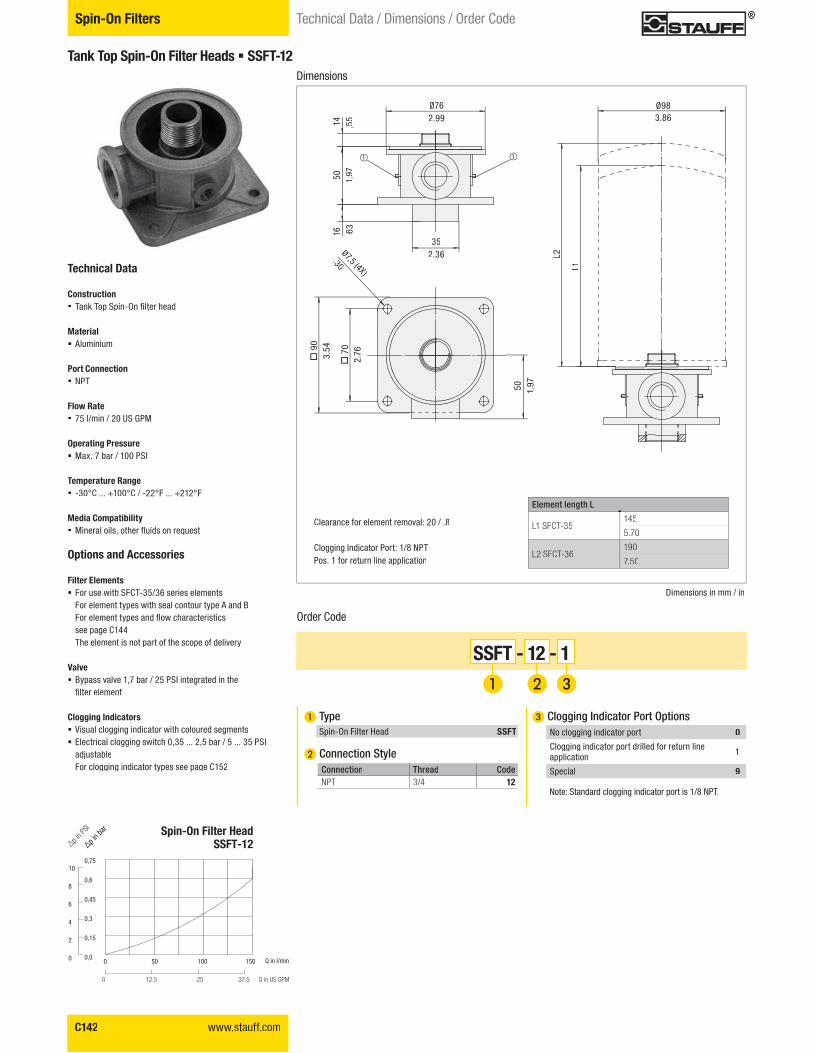
Tank Top Spin-On Filter Heads � SSFT-12
Technical Data
Construction � ;��<�;����������� ���������
Material � Aluminium
Port Connection� NPT
Flow Rate � 75 l/min / 20 US GPM
Operating Pressure� Max. 7 bar / 100 PSI
Temperature Range � -30°C ... +100°C / -22°F ... +212°F
Media Compatibility � ��������������������������������
Options and Accessories
Filter Elements � For use with SFCT-35/36 series elements
For element types with seal contour type A and B�����������!������������������������see page C144
The element is not part of the scope of delivery
Valve � Bypass valve 1,7 bar / 25 PSI integrated in the
�����������
Clogging Indicators � Visual clogging indicator with coloured segments� Electrical clogging switch 0,35 ... 2,5 bar / 5 ... 35 PSI
adjustableFor clogging indicator types see page C152
Dimensions
Order Code
SSFT - 12 - 1
� Type Spin-On Filter Head SSFT
� Connection StyleConnection !����� CodeNPT 3/4 12
� Clogging Indicator Port Options
Note: Standard clogging indicator port is 1/8 NPT.
No clogging indicator port 0
Clogging indicator port drilled for return lineapplication 1
Special 9
Dimensions in mm / in
Ø983.86
Ø762.99
352.36 L2
L1
14 .55
50 1.97
Ø7,5 (4X)
.30
�90
3.54
� 7
02.
76
50 1.97
16 .63
����� ���� �����
L1 SFCT-35145
5.70
L2 SFCT-36190
7.50
Clearance for element removal: 20 / .8
Clogging Indicator Port: 1/8 NPTPos. 1 for return line application
Spin-On Filter HeadSSFT-12
0,75
0,6
0,45
0,3
0,15
0,0
10
8
6
4
2
0
"p in b
ar
�p in P
SI
Q in l/min
Q in US GPM
0 50 100 150
0 12.5 25 37.5
www.stauff.com C143
Filtr
atio
nTe
chno
logy
C
Spin-On FiltersTechnical Data / Dimensions / Order Code
Dimensions
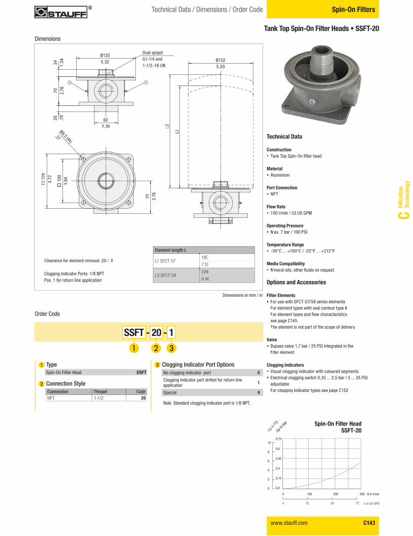
Order Code
SSFT - 20 - 1
� Type Spin-On Filter Head SSFT
� Connection StyleConnection !����� CodeNPT 1-1/2 20
� Clogging Indicator Port Options
Note: Standard clogging indicator port is 1/8 NPT.
No clogging indicator port 0
Clogging indicator port drilled for return lineapplication 1
Special 9
Dimensions in mm / in
Ø9,5 (4x)
.37
Ø1325.20
602.36
Ø1355.32
70 2.76
�10
03.
94
�12
04.
72
L2
L1
34 1.34
70 2.76
20 .78
����� ���� �����
L1 SFCT-57180
7.10
L2 SFCT-58226
8.90
Clearance for element removal: 20 / .8
Clogging Indicator Ports: 1/8 NPTPos. 1 for return line application
Dual spigotG1-1/4 and1-1/2–16 UN
Tank Top Spin-On Filter Heads � SSFT-20
Technical Data
Construction � ;��<�;����������� ��������
Material � Aluminium
Port Connection� NPT
Flow Rate � 200 l/min / 53 US GPM
Operating Pressure � Max. 7 bar / 100 PSI
Temperature Range � -30°C ... +100°C / -22°F ... +212°F
Media Compatibility � �������������������������������
Options and Accessories
Filter Elements � For use with SFCT-57/58 series elements
For element types with seal contour type A�����������!����������������������see page C145The element is not part of the scope of delivery
Valve � Bypass valve 1,7 bar / 25 PSI integrated in the
����������
Clogging Indicators � Visual clogging indicator with coloured segments� Electrical clogging switch 0,35 ... 2,5 bar / 5 ... 35 PSI
adjustableFor clogging indicator types see page C152
Spin-On Filter HeadSSFT-20
0,75
0,6
0,45
0,3
0,15
0,0
10
8
6
4
2
0
"p in b
ar
�p in P
SI
Q in l/min
Q in US GPM
0 100 200 300
0 25 50 75
C144 www.stauff.com
Spin-On Filters Technical Data / Dimensions
Order Code����� ����������"���������������� �������"�����������
Filter Paper # ���� ���$�����%�"��SFC-3510E SFC-3610E SFC-3525E SFC-3625E SFC-3503AE SFC-3603AE SFC-3510AE SFC-3610AE SFC-3525AE SFC-3625AESFCT-3510E SFCT-3610E SFCT-3525E SFCT-3625E SFCT-3525AE SFCT-3625AESFCT-3510AE SFCT-3610AE
�� ������&��'� +145 190 145 190145 190145 190 145 190
7.5 5.7 7.57.5 5.77.5 5.77.5 5.75.7
ß-Ratio ß10
��� ß10
��� ß25
���� ß25
���� ß3������ ß
3������ ß
10����� ß
10������ ß
25������ ß
25�����
Filter Area (cm2/in2)3305 4745 3305 4745 2140 3630 2140 3630 2140 3630510 735 510 735 330 560 330 560 330 560
Carton Quantity 1 1 1 1 1 1 1 1 1 1
,���� �4������&9�'�"�+0,9 1,3 0,9 1,3 0,9 1,3 0,9 1,3 0,9 1,32 2.6 2 2.6 2 2.6 2 2.6 2 2.6
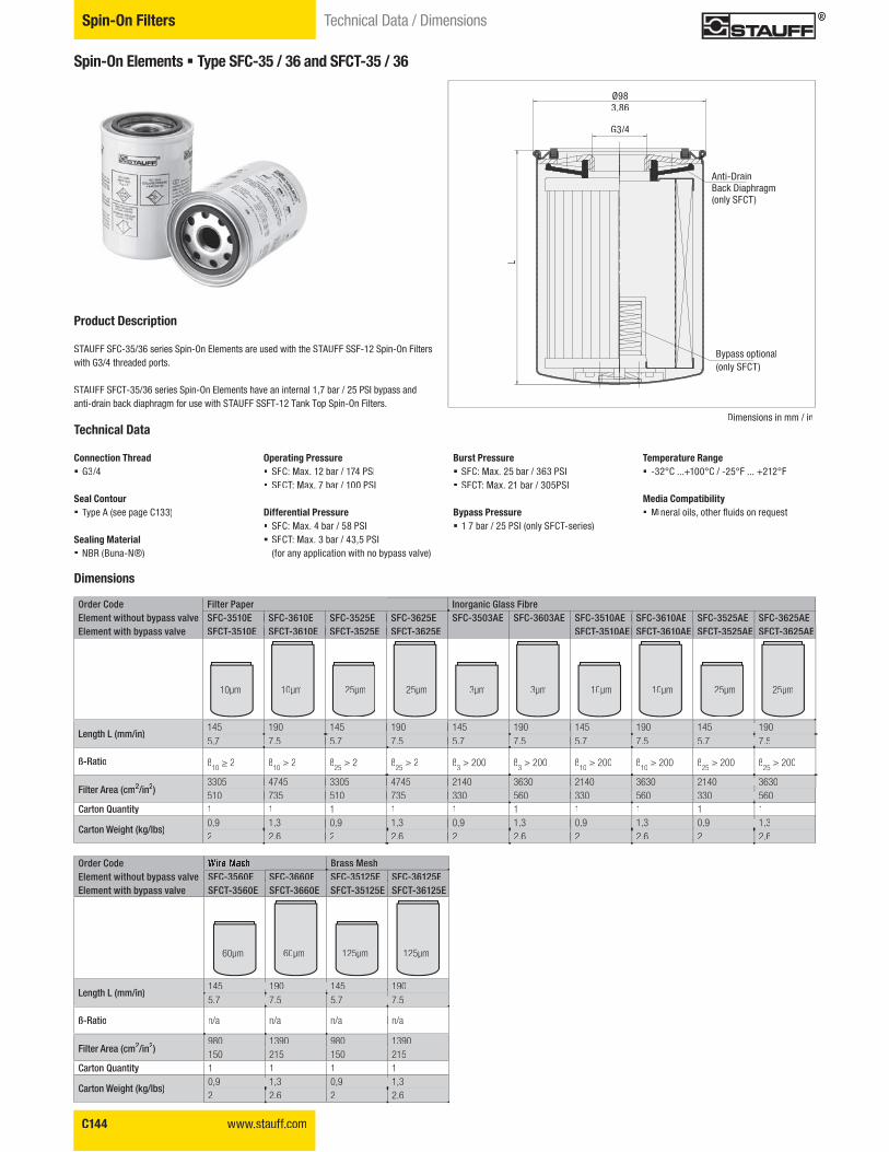
Spin-On Elements � Type SFC-35 / 36 and SFCT-35 / 36
Product Description
STAUFF SFC-35/36 series Spin-On Elements are used with the STAUFF SSF-12 Spin-On Filters with G3/4 threaded ports.
STAUFF SFCT-35/36 series Spin-On Elements have an internal 1,7 bar / 25 PSI bypass and anti-drain back diaphragm for use with STAUFF SSFT-12 Tank Top Spin-On Filters.
10μm 10μm 25μm 25μm 3μm 3μm 10μm 10μm 25μm 25μm
Dimensions
Order Code����� ����������"���������������� �������"�����������
;�����:���SFC-3560E SFC-3660E SFC-35125E SFC-36125ESFCT-3560E SFCT-3660E SFCT-35125E SFCT-36125E
�� ������&��'� +145 190 145 1905.7 7.5 5.7 7.5
ß-Ratio n/a n/an/a n/a
Filter Area (cm2/in2)980 1390 980 1390150 215 150 215
Carton Quantity 1 1 1 1
,���� �4������&9�'�"�+1,3 0,9 1,30,9
2 2.6 2 2.6
60μm 60μm 125μm 125μm
Technical Data
Connection Thread � G3/4
Seal Contour � Type A (see page C133)
Sealing Material � NBR (Buna-N®)
Operating Pressure � SFC: Max. 12 bar / 174 PSI� SFCT: Max. 7 bar / 100 PSI
Differential Pressure � SFC: Max. 4 bar / 58 PSI� SFCT: Max. 3 bar / 43,5 PSI
(for any application with no bypass valve)
Burst Pressure � SFC: Max. 25 bar / 363 PSI� SFCT: Max. 21 bar / 305PSI
Bypass Pressure � 1,7 bar / 25 PSI (only SFCT-series)
Temperature Range � -32°C ...+100°C / -25°F ... +212°F
Media Compatibility � �������������������������������
Dimensions in mm / in
L
Ø983.86
G3/4
Anti-DrainBack Diaphragm(only SFCT)
Bypass optional(only SFCT)
www.stauff.com C145
Filtr
atio
nTe
chno
logy
C
Spin-On FiltersTechnical Data / Dimensions
Order Code����� ����������"���������������� �������"�����������
Filter Paper # ���� ���$�����%�"��SFC-5710E SFC-5810E SFC-5725E SFC-5825E SFC-5703AE SFC-5803AE SFC-5710AE SFC-5810AE SFC-5725AE SFC-5825AESFCT-5710E SFCT-5810E SFCT-5725E SFCT-5825E SFCT-5703AE SFCT-5803AE SFCT-5710AE SFCT-5810AE SFCT-5725AE SFCT-5825AE
�� ������&��'� +180 226 180 226 180 226 180 226 180 2267.1 8.9 7.1 8.9 7.1 8.9 7.1 8.9 7.1 8.9
ß-Ratio ß10
���� ß10
���� ß25
��� ß25
��� ß3������ ß
3������ ß
10������ ß
10������ ß
25������ ß
25�����
Filter Area (cm2/in2)5890 4450 58905890 44507360 44507360 55605560910 700 910910 7001140 7001140 860860
Carton Quantity 1 1 1 1 1 1 1 1 1 1
,���� �4������&9�'�"�+1,85 1,4 1,851,85 1,41,85 1,41,85 1,41,4
3 4 3 4 3 4 3 4 3 4
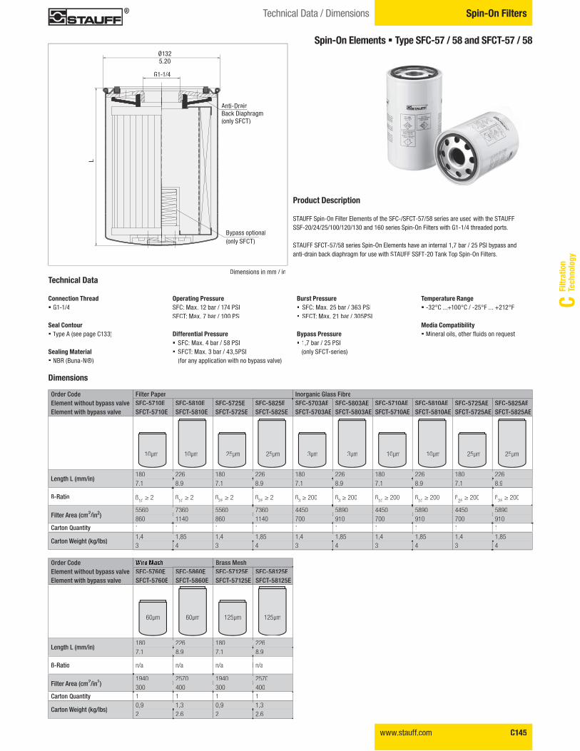
Spin-On Elements � Type SFC-57 / 58 and SFCT-57 / 58
10μm 10μm 25μm 25μm 3μm 3μm 10μm 10μm 25μm 25μm
60μm 60μm 125μm 125μm
Order Code����� ����������"���������������� �������"�����������
;�����:���SFC-5760E SFC-5860E SFC-57125E SFC-58125ESFCT-5760E SFCT-5860E SFCT-57125E SFCT-58125E
�� ������&��'� +180 226 180 2267.1 8.9 7.1 8.9
ß-Ratio n/a n/a n/a n/a
Filter Area (cm2/in2)1940 2570 1940 2570300 400 300 400
Carton Quantity 1 1 1 1
,���� �4������&9�'�"�+1,3 0,9 1,30,9
2 2.6 2 2.6
Technical Data
Connection Thread� G1-1/4
Seal Contour� Type A (see page C133)TT
Sealing Material� NBR (Buna-N®)
Operating PressureSFC: Max. 12 bar / 174 PSISFCT: Max. 7 bar / 100 PSI
Differential Pressure � SFC: Max. 4 bar / 58 PSI� SFCT: Max. 3 bar / 43,5PSI
(for any application with no bypass valve)
Burst Pressure � SFC: Max. 25 bar / 363 PSI� SFCT: Max. 21 bar / 305PSI
Bypass Pressure� 1,7 bar / 25 PSI
(only SFCT-series)
Temperature Range� -32°C ...+100°C / -25°F ... +212°F
Media Compatibility� �������������������������������
Product Description
STAUFF Spin-On Filter Elements of the SFC-/SFCT-57/58 series are used with the STAUFF SSF-20/24/25/100/120/130 and 160 series Spin-On Filters with G1-1/4 threaded ports.
STAUFF SFCT-57/58 series Spin-On Elements have an internal 1,7 bar / 25 PSI bypass and anti-drain back diaphragm for use with STAUFF SSFT-20 Tank Top Spin-On Filters.
Dimensions
Dimensions in mm / in
L
Ø1325.20
G1-1/4
Anti-DrainBack Diaphragm(only SFCT)
Bypass optional(only SFCT)
C146 www.stauff.com
Spin-On Filters Technical Data / Dimensions
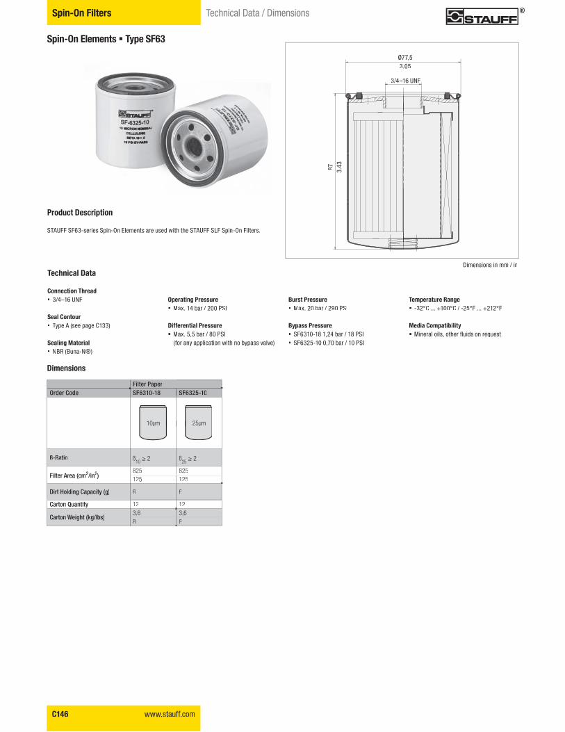
Spin-On Elements � Type SF63
Filter PaperOrder Code SF6310-18 SF6325-10
ß-Ratio ß10���� ß
25����
Filter Area (cm2/in2)825 825125 125
Dirt Holding Capacity (g) 6 6
Carton Quantity 12 12
,���� �4������&9�'�"�+3,6 3,68 8
10μm 25μm
Dimensions
Product Description
STAUFF SF63-series Spin-On Elements are used with the STAUFF SLF Spin-On Filters.
Dimensions in mm / in
Ø77,53.05
3/4–16 UNF
Technical Data
Connection Thread � 3/4–16 UNF
Seal Contour � Type A (see page C133)TT
Sealing Material � NBR (Buna-N®)
Operating Pressure � Max. 14 bar / 200 PSI
Differential Pressure � Max. 5,5 bar / 80 PSI
(for any application with no bypass valve)
Burst Pressure � Max. 20 bar / 290 PSI
Bypass Pressure � SF6310-18 1,24 bar / 18 PSI� SF6325-10 0,70 bar / 10 PSI
Temperature Range � -32°C ... +100°C / -25°F ... +212°F
Media Compatibility � �������������������������������
87 3.43
www.stauff.com C147
Filtr
atio
nTe
chno
logy
C
Spin-On FiltersTechnical Data / Dimensions
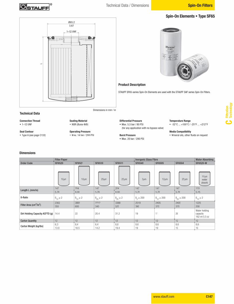
Spin-On Elements � Type SF65
Product Description
STAUFF SF65-series Spin-On Elements are used with the STAUFF SAF series Spin-On Filters.
Technical Data
Connection Thread � 1–12 UNF
Seal Contour � Type A (see page C133)TT
Sealing Material � NBR (Buna-N®)
Operating Pressure � Max. 14 bar / 200 PSI
Differential Pressure � Max. 5,5 bar / 80 PSI
(for any application with no bypass valve)
Burst Pressure � Max. 20 bar / 290 PSI
Temperature Range � -32°C ... +100°C / -25°F ... +212°F
Media Compatibility � �������������������������������
L
Ø93,23.67
Dimensions in mm / in
1–12 UNF
Dimensions
Filter Paper # ���� ���$�����%�"�� 4������"���"� �Order Code SF6520 SF6521 SF6510 SF6511 SF6549 SF6505 SF6504 SF6520-W
�� ������&��'� +147 204 147 204 147 147 147 1335.76 8.00 5.76 8.00 5.76 5.76 5.76 5.25
ß-Ratio ß10���� ß
10���� ß
25���� ß
25���� ß
3������ ß
12������ ß
25������ ß
10����
Filter Area (cm2/in2)2302 3881 2212 3388 2519 2405 2405 1225355 600 340 525 390 370 370 200
Dirt Holding Capacity ACFTD (g) 14.4 22 20.4 31.2 19 11 26Water holding capacity162 ml 5.5 oz
Carton Quantity 12 12 12 12 12 12 12 12
,���� �4������&9�'�"�+6,3 8,4 6,4 8,8 8,6 8,6 8,6 8,613.9 18.5 14.2 19.4 19 19 19 19
10μm 10μm 25μm 25μm 3μm 12μm 25μm10μm
μ μ μ μ μ μ μ waterabsorb
C148 www.stauff.com
Spin-On Filters Technical Data / Dimensions
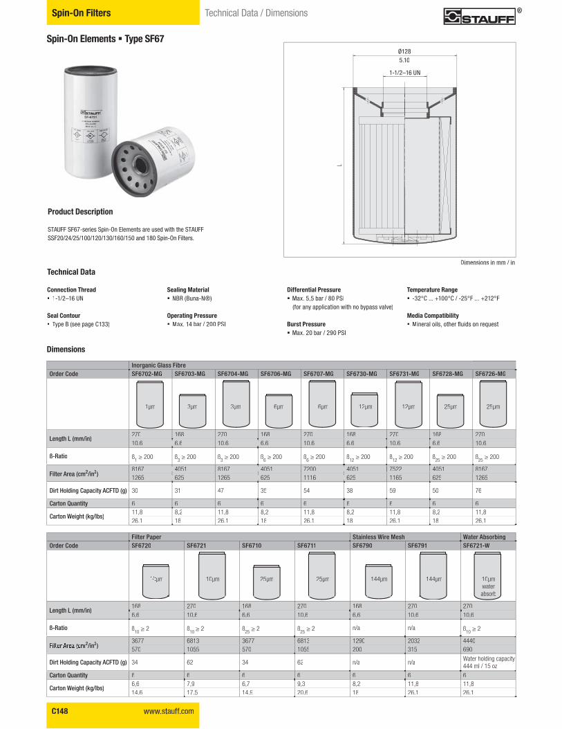
Spin-On Elements � Type SF67
Product Description
STAUFF SF67-series Spin-On Elements are used with the STAUFF SSF20/24/25/100/120/130/160/150 and 180 Spin-On Filters.
Filter Paper >��� �����4����:��� 4������"���"� �Order Code SF6720 SF6721 SF6710 SF6711 SF6790 SF6791 SF6721-W
�� ������&��'� +168 270 168 270 168 270 2706.6 10.6 6.6 10.6 6.6 10.6 10.6
ß-Ratio ß10 ��� ß10
��� ß25
���� ß25
���� n/a n/a ß10
����
2/in2)3677 6813 3677 6813 1290 2032 4440570 1055 570 1055 200 315 690
Dirt Holding Capacity ACFTD (g) 34 62 34 62 n/a n/aWater holding capacity444 ml / 15 oz
Carton Quantity 6 6 6 6 6 6 6
,���� �4������&9�'�"�+6,6 7,9 6,7 9,3 8,2 11,8 11,814.6 17.5 14.9 20.6 18 26.1 26.1
μm 10μm 25μm 25μm 144μm 144μm 10μmwaterabsorb
L
Ø1285.10
1-1/2–16 UN
# ���� ���$�����%�"��Order Code SF6702-MG SF6703-MG SF6704-MG SF6706-MG SF6707-MG SF6730-MG SF6731-MG SF6728-MG SF6726-MG
�� ������&��'� +270 168 270 168 270 168 270 168 27010.6 6.6 10.6 6.6 10.6 6.6 10.6 6.6 10.6
ß-Ratio ß1������ ß
3������ ß
3������ ß
6������ ß
6������ ß
12������ ß
12������ ß
25������ ß
25������
Filter Area (cm2/in2)8167 4051 8167 4051 7200 4051 7522 4051 81671265 625 1265 625 1116 625 1165 625 1265
Dirt Holding Capacity ACFTD (g) 30 31 47 35 54 38 59 50 76
Carton Quantity 6 6 6 6 6 6 6 6 6
,���� �4������&9�'�"�+11,8 8,2 11,8 8,2 11,8 8,2 11,8 8,2 11,826.1 18 26.1 18 26.1 18 26.1 18 26.1
1μm 3μm 3μm 6μm 6μm 12μm 12μm 25μm 25μm
Dimensions
Technical Data
Connection Thread � 1-1/2–16 UN
Seal Contour � Type B (see page C133)TT
Sealing Material � NBR (Buna-N®)
Operating Pressure � Max. 14 bar / 200 PSI
Differential Pressure � Max. 5,5 bar / 80 PSI
(for any application with no bypass valve)
Burst Pressure � Max. 20 bar / 290 PSI
Temperature Range � -32°C ... +100°C / -25°F ... +212°F
Media Compatibility � �������������������������������
Dimensions in mm / in
www.stauff.com C149
Filtr
atio
nTe
chno
logy
C
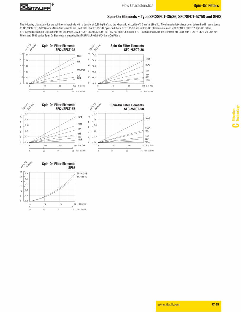
Spin-On FiltersFlow Characteristics
Spin-On Elements � Type SFC/SFCT-35/36, SFC/SFCT-57/58 and SF63
Spin-On Filter ElementsSF63
0 10 20 30
0 2.5 5 7.5
30
25
20
15
10
5
0
2,0
1,6
1,2
0,8
0,4
0,0
"p in b
ar
�p in P
SI
Q in l/min
Q in US GPM
SF3610-18SF3625-10
Spin-On Filter ElementsSFC-/SFCT-57
0 100 200 300 0 100 200 300
0 25 50 75 0 25 50 75
0,75
0,6
0,45
0,3
0,15
0,0
10
8
6
4
2
0
10
8
6
4
2
0
"p in b
ar
�p in P
SI
Q in l/min
Q in US GPM
10AE
25AE
10E
25E60E125E
Spin-On Filter ElementsSFC-/SFCT-58"p i
n bar
�p in P
SI
Q in l/min
Q in US GPM
10AE
25AE10E
25E60E125E
0,75
0,6
0,45
0,3
0,15
0,0
Spin-On Filter ElementsSFC-/SFCT-35
0 40 80 120
0 10 20 30
0,5
0,4
0,3
0,2
0,1
0,0
0,5
0,4
0,3
0,2
0,1
0,0
7.5
6
4.5
3
1.5
0
7.5
6
4.5
3
1.5
0
"p in b
ar
�p in P
SI
Q in l/min
Q in US GPM
10AE
10E
25E/25AE
60E125E
Spin-On Filter ElementsSFC-/SFCT-36
0 40 80 120
0 10 20 30
"p in b
ar
�p in P
SI
Q in l/min
Q in US GPM
10AE
25AE
10E
25E60E125E
The following characteristics are valid for mineral oils with a density of 0,85 kg/dm3 and the kinematic viscosity of 30 mm2/s (30 cSt). The characteristics have been determined in accordanceto ISO 3968. SFC-35/36 series Spin-On Elements are used with STAUFF SSF-12 Spin-On Filters, SFCT-35/36 series Spin-On Elements are used with STAUFF SSFT-12 Spin-On Filters, SFC-57/58 series Spin-On Elements are used with STAUFF SSF-20/24/25/100/120/130/160 Spin-On Filters, SFCT-57/58 series Spin-On Elements are used with STAUFF SSFT-20 Spin-On Filters and SF63 series Spin-On Elements are used with STAUFF SLF-02/03/04 Spin-On Filters.
C150 www.stauff.com
Spin-On Filters Flow Characteristics
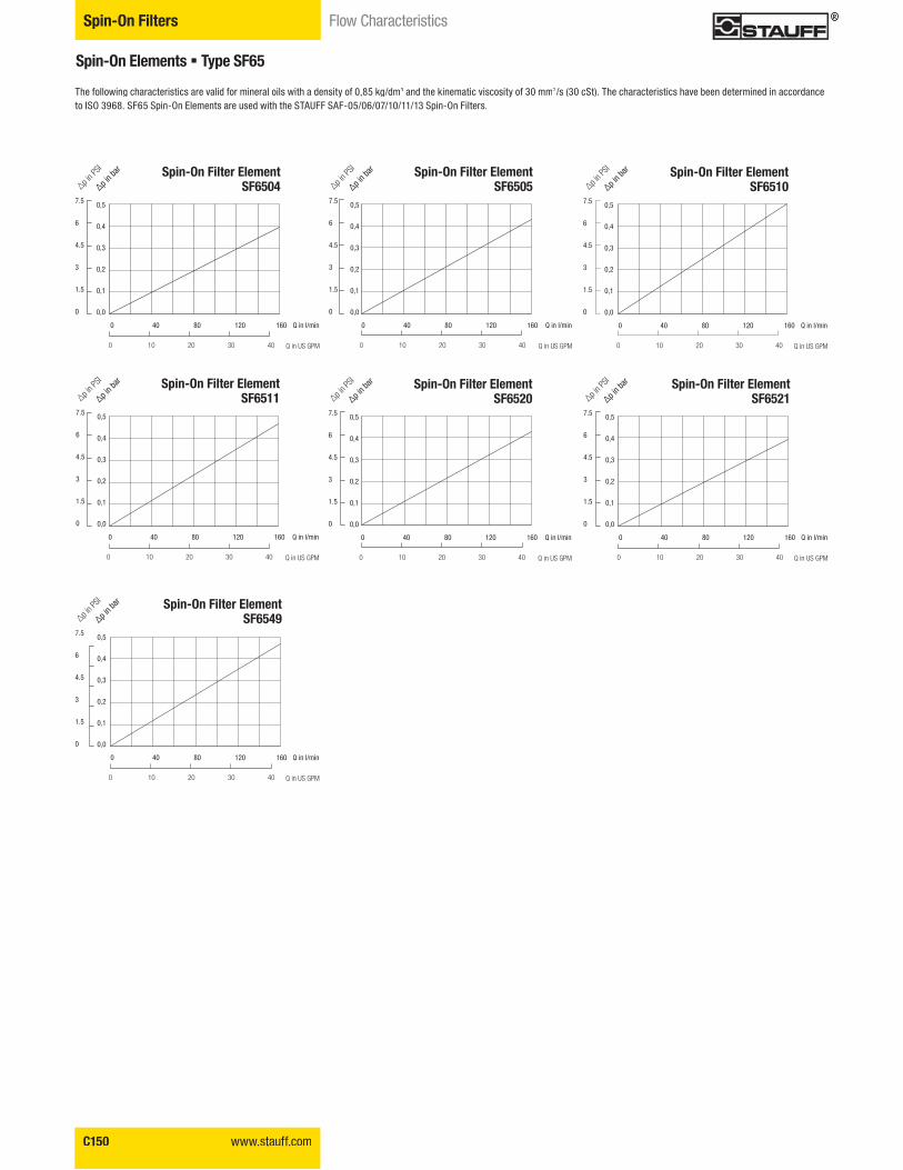
Spin-On Elements � Type SF65
Spin-On Filter ElementSF6520
0,5
0,4
0,3
0,2
0,1
0,0
7.5
6
4.5
3
1.5
0
"p in b
ar
�p in P
SI
Q in l/min
Q in US GPM
0 40 80 120 160
0 10 20 30 40
Spin-On Filter ElementSF6511
0,5
0,4
0,3
0,2
0,1
0,0
7.5
6
4.5
3
1.5
0
"p in b
ar
�p in P
SI
Q in l/min
Q in US GPM
0 40 80 120 160
0 10 20 30 40
Spin-On Filter ElementSF6505
0,5
0,4
0,3
0,2
0,1
0,0
7.5
6
4.5
3
1.5
0
"p in b
ar
�p in P
SI
Q in l/min
Q in US GPM
0 40 80 120 160
0 10 20 30 40
Spin-On Filter ElementSF6521
0,5
0,4
0,3
0,2
0,1
0,0
7.5
6
4.5
3
1.5
0
"p in b
ar
�p in P
SI
Q in l/min
Q in US GPM
0 40 80 120 160
0 10 20 30 40
Spin-On Filter ElementSF6549
0,5
0,4
0,3
0,2
0,1
0,0
7.5
6
4.5
3
1.5
0
"p in b
ar
�p in P
SI
Q in l/min
Q in US GPM
0 40 80 120 160
0 10 20 30 40
Spin-On Filter ElementSF6510
0,5
0,4
0,3
0,2
0,1
0,0
7.5
6
4.5
3
1.5
0
"p in b
ar
�p in P
SI
Q in l/min
Q in US GPM
0 40 80 120 160
0 10 20 30 40
Spin-On Filter ElementSF6504
0,5
0,4
0,3
0,2
0,1
0,0
7.5
6
4.5
3
1.5
0
"p in b
ar
�p in P
SI
Q in l/min
Q in US GPM
0 40 80 120 160
0 10 20 30 40
The following characteristics are valid for mineral oils with a density of 0,85 kg/dm3 and the kinematic viscosity of 30 mm2/s (30 cSt). The characteristics have been determined in accordanceto ISO 3968. SF65 Spin-On Elements are used with the STAUFF SAF-05/06/07/10/11/13 Spin-On Filters.
www.stauff.com C151
Filtr
atio
nTe
chno
logy
C
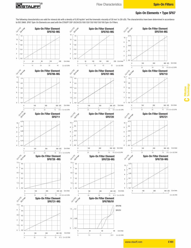
Spin-On FiltersFlow Characteristics
Spin-On Elements � Type SF67
Spin-On Filter ElementSF6711
0,75
0,6
0,45
0,3
0,15
0,0
10
8
6
4
2
0
Q in l/min
Q in US GPM
0 100 200 300 325
0 25 50 75 87.5
Spin-On Filter ElementSF6710
1,0
0,8
0,6
0,4
0,4
0,0
15
12
9
6
3
0
Q in l/min
Q in US GPM
0 100 200 300 325
0 25 50 75 87.5
Spin-On Filter ElementSF6721
0,75
0,6
0,45
0,3
0,15
0,0
10
8
6
4
2
0
Q in l/min
Q in US GPM
0 100 200 300 325
0 25 50 75 87.5
Spin-On Filter ElementSF6720
0,75
0,6
0,45
0,3
0,15
0,0
10
8
6
4
2
0
�p in P
SI
Q in l/min
Q in US GPM
0 100 200 300 325
0 25 50 75 87.5
0,5
0,4
0,3
0,2
0,1
0,0
7.5
6
4.5
3
1.5
0
0 100 200 300 325
0 25 50 75 87.5
Spin-On Filter Element SF6731-MG"p i
n bar
�p in P
SI
Q in l/min
Q in US GPM
1,0
0,8
0,6
0,4
0,4
0,0
15
12
9
6
3
0
0 100 200 300 325
0 25 50 75 87.5
Spin-On Filter Element SF6706-MG"p i
n bar
�p in P
SI
Q in l/min
Q in US GPM
Spin-On Filter Element SF6702-MG
1,0
0,8
0,6
0,4
0,2
0,0
15
12
9
5
3
0
"p in b
ar
�p in P
SI
Q in l/min
Q in US GPM
0 40 80 120 160
0 10 20 30 40
Spin-On Filter Element SF6703-MG
1,0
0,8
0,6
0,4
0,2
0,0
15
12
9
5
3
0
"p in b
ar
�p in P
SI
Q in l/min
Q in US GPM
0 50 100 150 200 250
0 15 30 45 50
0,5
0,4
0,3
0,2
0,1
0,0
7.5
6
4.5
3
1.5
0
0 100 200 300 325
0 25 50 75 87.5
Spin-On Filter Element SF6728-MG"p i
n bar
�p in P
SI
Q in l/min
Q in US GPM
0,5
0,4
0,3
0,2
0,1
0,0
7.5
6
4.5
3
1.5
0
0 100 200 300 325
0 25 50 75 87.5
Spin-On Filter Element SF6707-MG"p i
n bar
�p in P
SI
Q in l/min
Q in US GPM
0,5
0,4
0,3
0,2
0,1
0,0
7.5
6
4.5
3
1.5
0
0 100 200 300 325
0 25 50 75 87.5
Spin-On Filter ElementSF6726 -MG"p i
n bar
�p in P
SI
Q in l/min
Q in US GPM
0,75
0,6
0,45
0,3
0,15
0,0
0 100 200 300 325
Spin-On Filter ElementSF6730-MG
10
8
6
4
2
0
"p in b
ar
�p in P
SI
Q in l/min
Q in US GPM
10
8
6
4
2
0
0,75
0,6
0,45
0,3
0,15
0,0
0 100 200 300 325
0 25 50 75 87.5
Spin-On Filter ElementSF6704-MG"p i
n bar
�p in P
SI
Q in l/min
Q in US GPM
Spin-On Filter Element SF6790/91
0,1
0,05
0,0
1.5
.75
0
"p in b
ar
�p in P
SI
Q in l/min
Q in US GPM
0 30 60 90
0 7.5 15 22.5
SF6790
SF6791
"p in b
ar�p i
n PSI
"p in b
ar
�p in P
SI
"p in b
ar
"p in b
ar
�p in P
SI
The following characteristics are valid for mineral oils with a density of 0,85 kg/dm3 and the kinematic viscosity of 30 mm2/s (30 cSt). The characteristics have been determined in accordanceto ISO 3968. SF67 Spin-On Elements are used with the STAUFF SSF-20/24/25/100/120/130/160/150/180 Spin-On Filters.
C152 www.stauff.com
Spin-On Filters Clogging Indicators
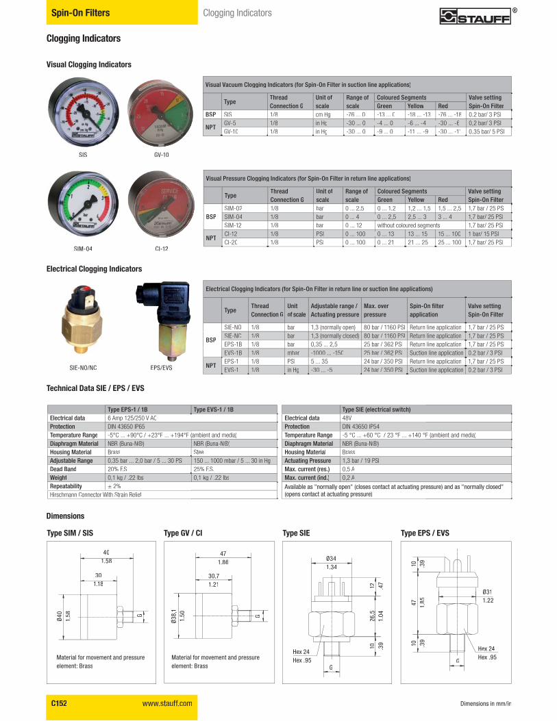
Clogging Indicators
Visual Vacuum Clogging Indicators (for Spin-On Filter in suction line applications)
Type!�����Connection G
Unit of scale
Range of scale
Coloured Segments ?���������� ��Spin-On FilterGreen Yellow Red
BSP SIS 1/8 cm Hg -76 ... 0 -13 ... 0 -18 ... -13 -76 ... -18 0,2 bar/ 3 PSI
NPTGV-5 1/8 in Hg -30 ... 0 -4 ... 0 -6 ... -4 -30 ... -6 0,2 bar/ 3 PSIGV-10 1/8 in Hg -30 ... 0 -9 ... 0 -11 ... -9 -30 ... -11 0,35 bar/ 5 PSI
Visual Pressure Clogging Indicators (for Spin-On Filter in return line applications)
Type!�����Connection G
Unit of scale
Range of scale
Coloured Segments ?���������� �Spin-On FilterGreen Yellow Red
BSPSIM-02 1/8 bar 0 ... 2,5 0 ... 1,2 1,2 ... 1,5 1,5 ... 2,5 1,7 bar / 25 PSISIM-04 1/8 bar 0 ... 4 0 ... 2,5 2,5 ... 3 3 ... 4 1,7 bar/ 25 PSISIM-12 1/8 bar 0 ... 12 without coloured segments 1,7 bar/ 25 PSI
NPTCI-12 1/8 PSI 0 ... 100 0 ... 13 13 ... 15 15 ... 100 1 bar/ 15 PSICI-20 1/8 PSI 0 ... 100 0 ... 21 21 ... 25 25 ... 100 1,7 bar/ 25 PSI
Electrical Clogging Indicators (for Spin-On Filter in return line or suction line applications)
Type!������Connection G
Unit of scale
��@����"����� ���'�Actuating pressure
:�J�������pressure
>�� KX �Z������application
?���������� �Spin-On Filter
BSP
SIE-NO 1/8 bar 1,3 (normally open) 80 bar / 1160 PSI Return line application 1,7 bar / 25 PSISIE-NC 1/8 bar 1,3 (normally closed) 80 bar / 1160 PSI Return line application 1,7 bar / 25 PSIEPS-1B 1/8 bar 0,35 ... 2,5 25 bar / 362 PSI Return line application 1,7 bar / 25 PSIEVS-1B 1/8 mbar -1000 ... -150 25 bar / 362 PSI Suction line application 0,2 bar / 3 PSI
NPTEPS-1 1/8 PSI 5 ... 35 24 bar / 350 PSI Return line application 1,7 bar / 25 PSIEVS-1 1/8 in Hg -30 ... -5 24 bar / 350 PSI Suction line application 0,2 bar / 3 PSI
Visual Clogging Indicators
Electrical Clogging Indicators
Type EPS-1 / 1B Type EVS-1 / 1BElectrical data 6 Amp 125/250 V ACProtection DIN 43650 IP65Temperature Range -5°C ... +90°C / +23°F ... +194°F (ambient and media)[���������:������� NBR (Buna-N®) NBR (Buna-N®)Housing Material Brass Steel��@����"���� �� 0,35 bar ... 2,0 bar / 5 ... 30 PSI 150 ... 1000 mbar / 5 ... 30 in HgDead Band 20% F.S. 25% F.S.4����� 0,1 kg / .22 lbs 0,1 kg / .22 lbs������"����� ± 2%Hirschmann Connector With Strain Relief
!����>#��&�����������������+Electrical data 48VProtection DIN 43650 IP54Temperature Range -5 °C ... +60 °C / 23 °F ... +140 °F (ambient and media)[���������:������� NBR (Buna-N®)Housing Material BrassActuating Pressure 1,3 bar / 19 PSIMax. current (res.) 0,5 AMax. current (ind.) 0,2 A
Available as "normally open" (closes contact at actuating pressure) and as "normally closed" (opens contact at actuating pressure)
Technical Data SIE / EPS / EVS
SIS
SIM-04
GV-10
CI-12
Type GV / CI
471.86
30,71.21
G
Ø38
,11.
50
Material for movement and pressureelement: Brass
Type SIM / SIS
401.58
301.18
G
Ø40
1.58
Material for movement and pressureelement: Brass
Dimensions
Dimensions in mm/in
Type EPS / EVS
10 .39
Hex 24Hex .95
Ø311.22
G
10 .39
47 1.85
Type SIE
12 .47
Hex 24Hex .95
Ø341.34
G
10 .39
26,5,
1.04
SIE-NO/NC EPS/EVS