spin-on fuel filter/water separators fuel... · spin-on fuel filter/water separators ... test...
TRANSCRIPT
400 SeriesSpin-on Fuel Filter/Water Separators
Contact Information:Parker Hannifin CorporationRacor DivisionP.O. Box 32083400 Finch RoadModesto, CA 95353
phone 800 344 3286 209 521 7860fax 209 529 [email protected]
www.parker.com/racorwww.parker.com/racorproducts
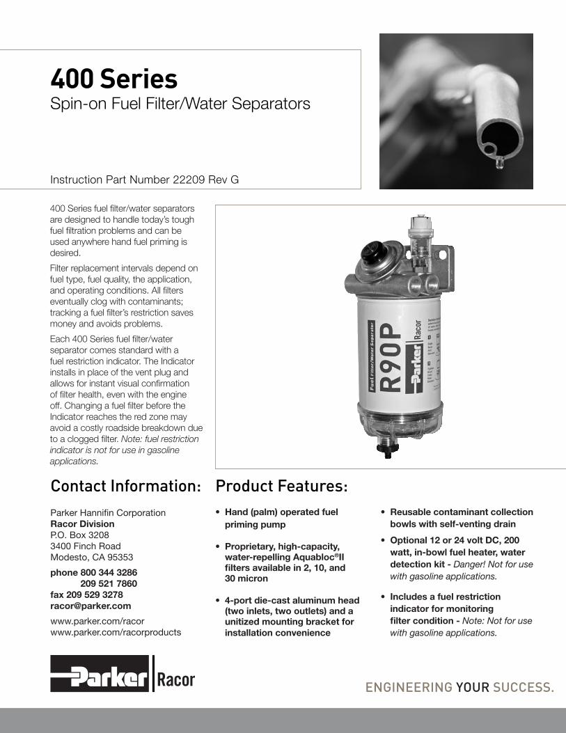
400 Series fuel filter/water separators are designed to handle today’s tough fuel filtration problems and can be used anywhere hand fuel priming is desired.
Filter replacement intervals depend on fuel type, fuel quality, the application, and operating conditions. All filters eventually clog with contaminants; tracking a fuel filter’s restriction saves money and avoids problems.
Each 400 Series fuel filter/water separator comes standard with a fuel restriction indicator. The Indicator installs in place of the vent plug and allows for instant visual confirmation of filter health, even with the engine off. Changing a fuel filter before the Indicator reaches the red zone may avoid a costly roadside breakdown due to a clogged filter. Note: fuel restriction indicator is not for use in gasoline applications.
Instruction Part Number 22209 Rev G
Product Features:• Hand (palm) operated fuel
priming pump
• Proprietary, high-capacity, water-repelling Aquabloc®II filters available in 2, 10, and 30 micron
• 4-port die-cast aluminum head (two inlets, two outlets) and a unitized mounting bracket for installation convenience
• Reusable contaminant collection bowls with self-venting drain
• Optional 12 or 24 volt DC, 200 watt, in-bowl fuel heater, water detection kit - Danger! Not for use with gasoline applications.
• Includes a fuel restriction indicator for monitoring filter condition - Note: Not for use with gasoline applications.
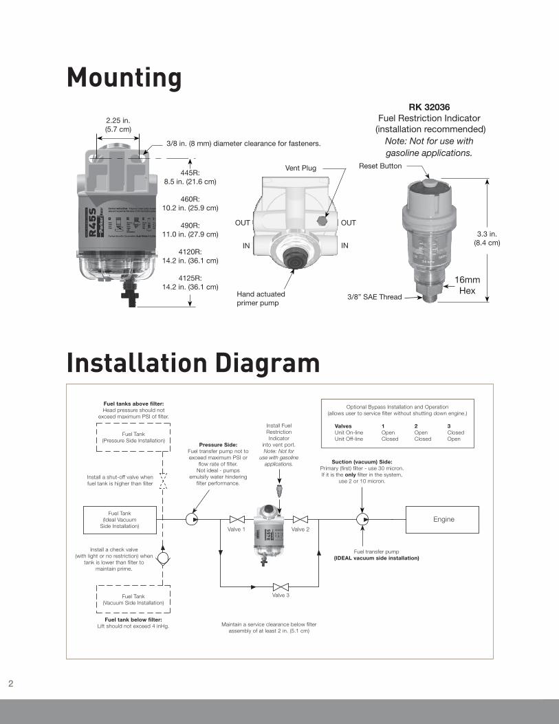
Mounting
Installation Diagram
TOP VIEW
3/8 in. (8 mm) diameter clearance for fasteners.
2.25 in.(5.7 cm)
445R:8.5 in. (21.6 cm)
460R:10.2 in. (25.9 cm)
490R:11.0 in. (27.9 cm)
4120R:14.2 in. (36.1 cm)
4125R:14.2 in. (36.1 cm)
Vent Plug
Hand actuated primer pump
OUT OUT
IN IN
3/8” SAE Thread
Reset Button
3.3 in.(8.4 cm)
RK 32036 Fuel Restriction Indicator
(installation recommended) Note: Not for use with gasoline applications.
16mm Hex
Valve 1 Valve 2
Fuel tanks above filter:Head pressure should not
exceed maximum PSI of filter.
Fuel Tank(Pressure Side Installation)
Install a shut-off valve when fuel tank is higher than filter
Fuel tank below filter:Lift should not exceed 4 inHg.
Fuel Tank(Ideal Vacuum
Side Installation)
Fuel Tank(Vacuum Side Installation)
Install a check valve (with light or no restriction) when
tank is lower than filter to maintain prime.
Pressure Side:Fuel transfer pump not to exceed maximum PSI or
flow rate of filter. Not ideal - pumps
emulsify water hindering filter performance.
Fuel transfer pump(IDEAL vacuum side installation)
Engine
Maintain a service clearance below filter assembly of at least 2 in. (5.1 cm)
Valve 3
Optional Bypass Installation and Operation(allows user to service filter without shutting down engine.)
Valves 1 2 3 Unit On-line Open Open Closed Unit Off-line Closed Closed Open
Suction (vacuum) Side: Primary (first) filter - use 30 micron.If it is the only filter in the system,
use 2 or 10 micron.
Install Fuel Restriction Indicator
into vent port.Note: Not for
use with gasoline applications.
2
Refer to Mounting and Installation
Diagram and install as follows:
1. Make sure engine is off and cool
to touch.
2. 445R, 460R and 490R: Apply thread
sealant to NPT fittings (do not use
thread tapes as particles may break
off and contribute to clogging filter).
4120R and 4125R: Apply motor oil
or diesel fuel to O-ring on UNF/SAE
fittings.
3. Thread fittings into appropriate
fuel ports and tighten snugly. Plug
unused ports (if any) with port plugs
and tighten snugly.
4. Mount filter vertically in a protected
area and away from heat sources.
Maintain at least 2.0” (5.1 cm) of
clearance below filter for draining
water and servicing filter.
5. Attach fuel lines to filter. Avoid tight
bends and rubbing areas when
routing hose.
6. Connect water probe and heater
wires (if equipped).
7. Open vent plug and operate hand
primer pump until fuel purges
from vent.
8. Close vent plug or thread Indicator
and tighten snugly with a 16mm
wrench and start engine. Correct as
necessary with engine off
Note: A fuel restriction indicator is
supplied as standard with this unit. It
is installed in place of the air vent plug,
if desired. As the filter slowly becomes
plugged with contaminants, the visual
indicator moves down towards the red
“service area” and holds this position.
To reset the restriction indicator, simply
push the button on the top down
prior to starting engine. When venting
the filter, never apply torque to the
restriction indicator body. Only use an
open 16 mm hex wrench on the brass
nut to open and close the vent hole.
Installation GuidelinesServiceFilter replacement frequency is determined by contamination level in fuels. Fuel flow to engine becomes restricted as filter gradually plugs with contaminants, resulting in noticeable power loss and/or hard starting. As a guideline, change filter every 500 hours, 10,000 miles, every other oil change, annually, or at first indication of power loss, whichever occurs first. Always carry extra replacement filters as one tankful of excessively dirty fuel can quickly plug a filter.
If a Fuel Restriction Indicator has been installed visual indication of the filter life can easily be monitored.
1. Make sure engine is off and cool to touch.
2. Close all fuel valves, if applicable, to make sure excess fuel does dot spill during servicing.
3. Disconnect water probe and heater connectors, if equipped.
4. Open vent plug on mounting head.
5. Drain unit of fuel.
6. Remove bowl and filter. Dispose of filter properly. Bowl is reusable.
7. Lubricate new filter seals with motor oil or clean fuel and install only with new filter.
8. Re-install bowl and tighten by hand only - do not use tools.
9. Connect water probe and heater connectors, if equipped.
10. Open all fuel valves, if applicable.
11. Operate hand primer pump until fuel purges from vent.
12. Close vent plug and start engine. Correct as necessary with engine off.
Draining the Collection BowlWater is heavier than fuel and will settle to bottom of bowl and appear different in color if
collected in a clear jar. In high humidity environments, check bowl frequently (daily if a poor fuel source is suspected). 400 Series bowls are equipped with a water sensor port that will accept a water probe (sold separately) and will alert operator of a high water condition in the filter.
1. Make sure engine is off and cool to touch.
2. Open vent plug or loosen restriction indicator using a 16mm wrench.
3. Drain water from filter by opening self-venting drain. Close as soon as all water has evacuated.
If drain is open too long, the entire filter may drain completely of water and fuel.
4. Follow priming instructions.
Priming1. Prime filter by operating hand
primer pump until fuel spills out of vent port. Using a 16mm open-end wrench loosen restriction indicator to bleed trapped air.
2. Close vent plug snugly. Or use a 16mm open-end wrench to tighten restriction indicator until snug (Do not tighten using the restriction indicator body, as it will be damaged).
3. Verify all other connections are tight.
4. Start engine and check for leaks. Correct as necessary with engine off.
Trouble ShootingIf filter fails to hold prime, first check
vent plug, drain valve, fittings, head,
filter, and bowl are properly tightened.
Next, check fuel line connections
and verify they are free of pinches or
unnecessary bends and check to see if
fuel tank strainer (or pick-up tube) is
clogged. If problems persist and filter
is new, call Racor Technical Support
at 800-344-3286, 8 AM to 5 PM, Pacific
Standard Time.
3
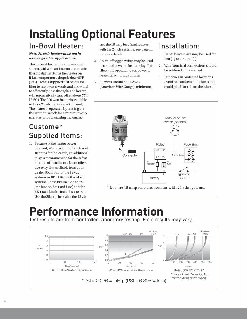
Performance InformationTest results are from controlled laboratory testing. Field results may vary.
*PSI x 2.036 = inHg. (PSI x 6.895 = kPa)
SAE J1839 Water Separation
50 100 150
100
98
96
94
92
900
Time (minutes)
%Efficient
4120 and4125490460445
8
6
4
2
0
PSI*
600500400300200100
Grams
SAE J905 SOFTC-2A Contaminant Capacity, 10 micron Aquabloc® media
SAE J905 Fuel Flow Restriction
1.0
0.6
0.4
0.2
12090603000.0
4120 and4125490460445
PSI*
Flow (GPH)
0.8
Installing Optional FeaturesIn-Bowl Heater:Note: Electric heaters must not be used in gasoline applications.
The in-bowl heater is a cold weather starting aid with an internal automatic thermostat that turns the heater on if fuel temperature drops below 45°F (7°C). Heat is supplied just below the filter to melt wax crystals and allow fuel to efficiently pass through. The heater will automatically turn off at about 75°F (24°C). The 200 watt heater is available in 12 or 24 vdc (volts, direct current). The heater is operated by turning on the ignition switch for a minimum of 5 minutes prior to starting the engine.
Customer Supplied Items:
Because of the heater power 1. demand, 20 amps for the 12 vdc and 10 amps for the 24 vdc, an additional relay is recommended for the safest method of installation. Racor offers two relay kits, available from your dealer, RK 11861 for the 12 vdc systems or RK 11862 for the 24 vdc systems. These kits include an in-line fuse holder (and fuse) and the RK 11862 kit also includes a resistor. Use the 25 amp fuse with the 12 vdc
and the 15 amp fuse (and resistor) with the 24 vdc systems. See page 11 for more details.
An on-off toggle switch may be used 2. to control power to heater relay. This allows the operator to cut power to heater relay during summer.
All wires should be 14 AWG 3. (American Wire Gauge), minimum.
Installation:Either heater wire may be used for 1. Hot (+) or Ground (-).
Wire/terminal connections should 2. be soldered and crimped.
Run wires in protected locations. 3. Avoid hot surfaces and places that could pinch or rub on the wires.
* Use the 15 amp fuse and resistor with 24 vdc systems.
Battery- + Ignition
Switch
* fuse* resistor
Relay
C4 B2
A5 E3Connector
Fuse Box
1 amp fuse
Manual on-off switch (optional)
4
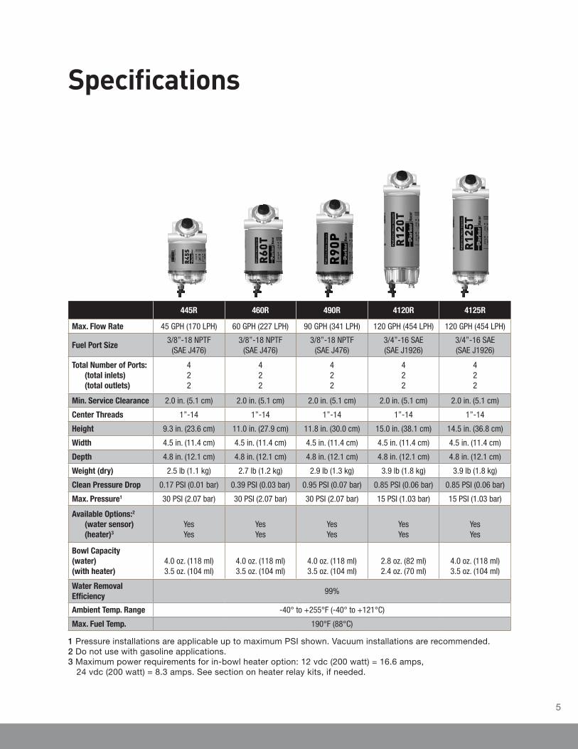
Specifications
1 Pressure installations are applicable up to maximum PSI shown. Vacuum installations are recommended. 2 Do not use with gasoline applications. 3 Maximum power requirements for in-bowl heater option: 12 vdc (200 watt) = 16.6 amps,
24 vdc (200 watt) = 8.3 amps. See section on heater relay kits, if needed.
445R 460R 490R 4120R 4125R
Max. Flow Rate 45 GPH (170 LPH) 60 GPH (227 LPH) 90 GPH (341 LPH) 120 GPH (454 LPH) 120 GPH (454 LPH)
Fuel Port Size3/8”-18 NPTF
(SAE J476)3/8”-18 NPTF
(SAE J476)3/8”-18 NPTF
(SAE J476)3/4”-16 SAE(SAE J1926)
3/4”-16 SAE(SAE J1926)
Total Number of Ports:(total inlets) (total outlets)
422
422
422
422
422
Min. Service Clearance 2.0 in. (5.1 cm) 2.0 in. (5.1 cm) 2.0 in. (5.1 cm) 2.0 in. (5.1 cm) 2.0 in. (5.1 cm)
Center Threads 1”-14 1”-14 1”-14 1”-14 1”-14
Height 9.3 in. (23.6 cm) 11.0 in. (27.9 cm) 11.8 in. (30.0 cm) 15.0 in. (38.1 cm) 14.5 in. (36.8 cm)
Width 4.5 in. (11.4 cm) 4.5 in. (11.4 cm) 4.5 in. (11.4 cm) 4.5 in. (11.4 cm) 4.5 in. (11.4 cm)
Depth 4.8 in. (12.1 cm) 4.8 in. (12.1 cm) 4.8 in. (12.1 cm) 4.8 in. (12.1 cm) 4.8 in. (12.1 cm)
Weight (dry) 2.5 lb (1.1 kg) 2.7 lb (1.2 kg) 2.9 lb (1.3 kg) 3.9 lb (1.8 kg) 3.9 lb (1.8 kg)
Clean Pressure Drop 0.17 PSI (0.01 bar) 0.39 PSI (0.03 bar) 0.95 PSI (0.07 bar) 0.85 PSI (0.06 bar) 0.85 PSI (0.06 bar)
Max. Pressure1 30 PSI (2.07 bar) 30 PSI (2.07 bar) 30 PSI (2.07 bar) 15 PSI (1.03 bar) 15 PSI (1.03 bar)
Available Options:2
(water sensor) (heater)3
YesYes
YesYes
YesYes
YesYes
YesYes
Bowl Capacity (water) (with heater)
4.0 oz. (118 ml)3.5 oz. (104 ml)
4.0 oz. (118 ml)3.5 oz. (104 ml)
4.0 oz. (118 ml)3.5 oz. (104 ml)
2.8 oz. (82 ml)2.4 oz. (70 ml)
4.0 oz. (118 ml)3.5 oz. (104 ml)
Water Removal Efficiency
99%
Ambient Temp. Range -40° to +255°F (-40° to +121°C)
Max. Fuel Temp. 190°F (88°C)
5

445R, 460R, and 490RReplacement PartsPart Number Description
1. RK 32036Fuel Restriction Indicator 3/8” SAE Threads
Note: Not for use in gasoline applications
2. RK 10110 Metal Vent Plug Kit (3/8”-24 SAE)
3. RK 22425
RK22168-05BP
Mounting Head Kit (3/8”-18 NPTF Ports)(includes head, #2, #3 and #4)
Mounting Head Kit (16 mm x 1.5 Ports)(includes head, #2, #3 and #4)
4. RK 22798 Bypass Valve Kit
5. RK 20505 Filter Gasket Kit
6. Replacement Filters
445R
R45S or R47S 2 micron
R45T 10 micron
R45P 30 micron
460R
R60S 2 micron
R60T 10 micron
R60P 30 micron
490R
R90S 2 micron
R90T 10 micron
R90P 30 micron
7. RK 22333 Bowl Gasket Kit
8. Replacement Bowl Kits (includes clear bowl, #6, #8, and #9)
RK 21113-13-11 Clear Bowl Kit
RK 22616-011 Heated Bowl Kit (Clear bowl with 12 vdc heater)
RK 22616-021 Heated Bowl Kit (Clear bowl with 24 vdc heater)
9. RK 20126 Plug Kit (1/2”-20 SAE)
10. RK 30476 Self-Venting Drain Kit
Additional Parts (not shown)
RK 223231 Heater Connector Kit
1 In-bowl heater may require a Heater Relay Kit. Maximum power requirements: 12 vdc = 16.6 amps, 24 vdc = 8.3 amps.
Note: Heater option must not be used with gasoline applications.
2
6
4
7
10
3
5
8
9
1
6
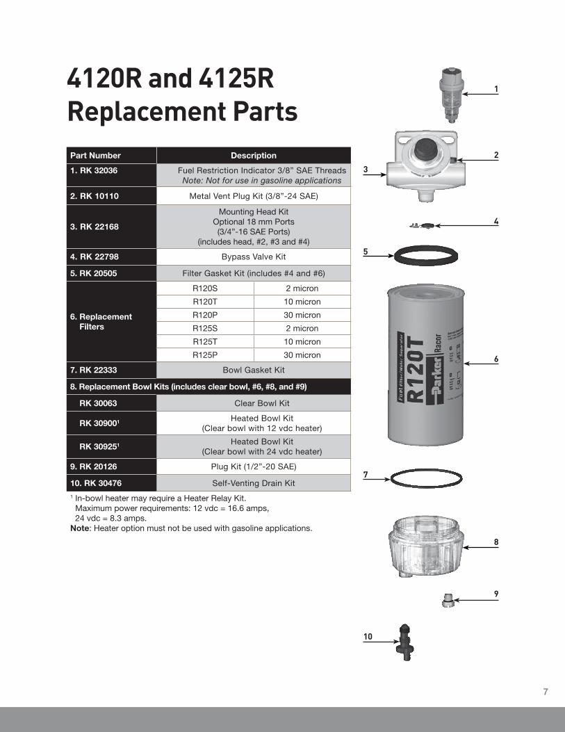
4120R and 4125RReplacement PartsPart Number Description
1. RK 32036 Fuel Restriction Indicator 3/8” SAE Threads Note: Not for use in gasoline applications
2. RK 10110 Metal Vent Plug Kit (3/8”-24 SAE)
3. RK 22168
Mounting Head Kit Optional 18 mm Ports(3/4”-16 SAE Ports)
(includes head, #2, #3 and #4)
4. RK 22798 Bypass Valve Kit
5. RK 20505 Filter Gasket Kit (includes #4 and #6)
6. Replacement Filters
R120S 2 micron
R120T 10 micron
R120P 30 micron
R125S 2 micron
R125T 10 micron
R125P 30 micron
7. RK 22333 Bowl Gasket Kit
8. Replacement Bowl Kits (includes clear bowl, #6, #8, and #9)
RK 30063 Clear Bowl Kit
RK 309001 Heated Bowl Kit (Clear bowl with 12 vdc heater)
RK 309251 Heated Bowl Kit (Clear bowl with 24 vdc heater)
9. RK 20126 Plug Kit (1/2”-20 SAE)
10. RK 30476 Self-Venting Drain Kit
1 In-bowl heater may require a Heater Relay Kit. Maximum power requirements: 12 vdc = 16.6 amps, 24 vdc = 8.3 amps.
Note: Heater option must not be used with gasoline applications.
2
6
5
9
7
10
3
4
8
1
7
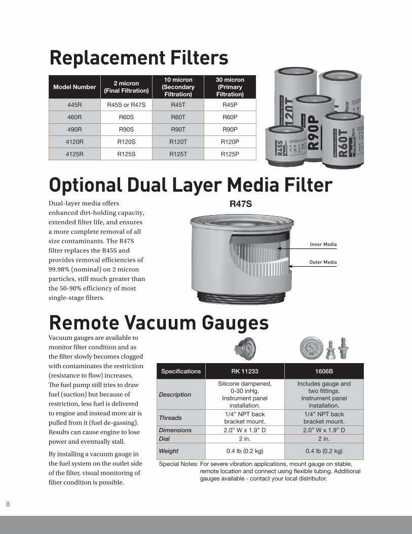
Model Number2 micron
(Final Filtration)
10 micron(Secondary Filtration)
30 micron(Primary Filtration)
445R R45S or R47S R45T R45P
460R R60S R60T R60P
490R R90S R90T R90P
4120R R120S R120T R120P
4125R R125S R125T R125P
Replacement Filters
Optional Dual Layer Media FilterDual-layer media offers
enhanced dirt-holding capacity,
extended filter life, and ensures
a more complete removal of all
size contaminants. The R47S
filter replaces the R45S and
provides removal efficiencies of
99.98% (nominal) on 2 micron
particles, still much greater than
the 50-90% efficiency of most
single-stage filters.
R47S
Inner Media
Outer Media
Remote Vacuum GaugesVacuum gauges are available to
monitor filter condition and as
the filter slowly becomes clogged
with contaminates the restriction
(resistance to flow) increases.
The fuel pump still tries to draw
fuel (suction) but because of
restriction, less fuel is delivered
to engine and instead more air is
pulled from it (fuel de-gassing).
Results can cause engine to lose
power and eventually stall.
By installing a vacuum gauge in
the fuel system on the outlet side
of the filter, visual monitoring of
filter condition is possible.
Specifications RK 11233 1606B
Description
Silicone dampened, 0-30 inHg.
Instrument panel installation.
Includes gauge and two fittings.
Instrument panel installation.
Threads1/4” NPT back bracket mount.
1/4” NPT back bracket mount.
Dimensions 2.0” W x 1.9” D 2.0” W x 1.9” DDial 2 in. 2 in.
Weight 0.4 lb (0.2 kg) 0.4 lb (0.2 kg)
Special Notes: For severe vibration applications, mount gauge on stable, remote location and connect using flexible tubing. Additional gauges available - contact your local distributor.
8
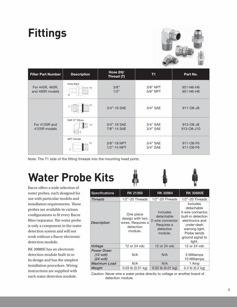
Filter Part Number DescriptionHose (H)/Thread (T)
T1 Part No.
For 445R, 460R, and 490R models
3/8”1/2”
3/8” NPT3/8” NPT
951-N6-H6951-N6-H8
For 4120R and4125R models
3/4”-16 SAE 3/4” SAE 911-O8-J8
3/4”-16 SAE7/8”-14 SAE
3/4” SAE3/4” SAE
913-O8-J8913-O8-J10
3/8”-18 NPT1/2”-14 NPT
3/4” SAE3/4” SAE
911-O8-F6911-O8-F8
Hose Barb
H
T1
T T1
SAE 37* Elbow
T
T1
NPT Female
T1
T
Note: The T1 side of the fitting threads into the mounting head ports.
Fittings
Specifications RK 21069 RK 30964 RK 30880E
Threads 1/2”-20 Threads 1/2”-20 Threads 1/2”-20 Threads
Description
One piece design with two
wires. Requires a detection module.
Includes detachable
2-wire connector. Requires a detection module.
Includes detachable
3-wire connector, built-in detection electronics and
under-dash warning light. Probe sends
ground signal to light.
Voltage 12 or 24 vdc 12 or 24 vdc 12 or 24 vdcPower Draw:
(12 volt) (24 volt)
N/A N/A 5 Milliamps10 Milliamps
Maximum Load N/A N/A 1 AmpWeight 0.03 lb (0.01 kg) 0.02 lb (0.01 kg) 0.4 lb (0.2 kg)
Caution: Never wire a water probe directly to voltage or another brand of detection module.
Water Probe KitsRacor offers a wide selection of
water probes, each designed for
use with particular models and
installation requirements. These
probes are available in various
configurations to fit every Racor
filter/separator. The water probe
is only a component in the water
detection system and will not
work without a Racor electronic
detection module.
RK 30880E has an electronic
detection module built-in to
its design and has the simplest
installation procedure. Wiring
instructions are supplied with
each water detection module.
9
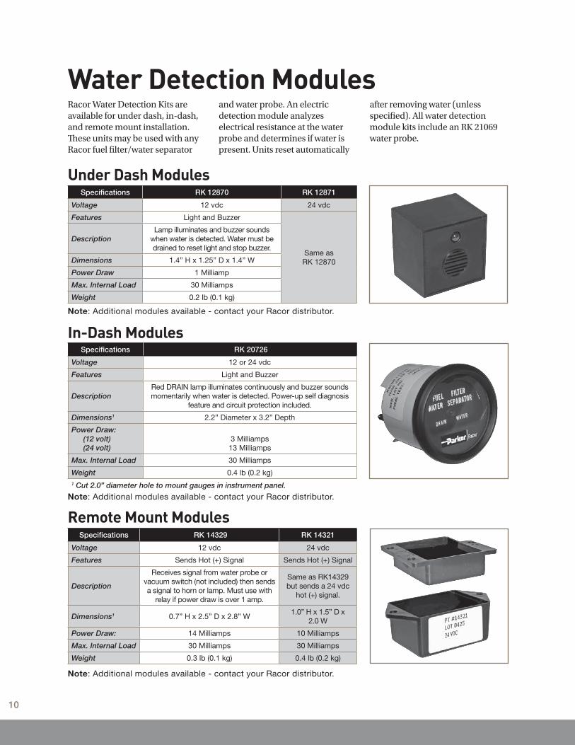
Water Detection ModulesRacor Water Detection Kits are available for under dash, in-dash, and remote mount installation. These units may be used with any Racor fuel filter/water separator
and water probe. An electric detection module analyzes electrical resistance at the water probe and determines if water is present. Units reset automatically
Under Dash ModulesSpecifications RK 12870 RK 12871
Voltage 12 vdc 24 vdc
Features Light and Buzzer
Same as RK 12870
DescriptionLamp illuminates and buzzer sounds
when water is detected. Water must be drained to reset light and stop buzzer.
Dimensions 1.4” H x 1.25” D x 1.4” W
Power Draw 1 Milliamp
Max. Internal Load 30 Milliamps
Weight 0.2 lb (0.1 kg)
Note: Additional modules available - contact your Racor distributor.
In-Dash Modules Specifications RK 20726
Voltage 12 or 24 vdc
Features Light and Buzzer
DescriptionRed DRAIN lamp illuminates continuously and buzzer sounds momentarily when water is detected. Power-up self diagnosis
feature and circuit protection included.
Dimensions1 2.2” Diameter x 3.2” Depth
Power Draw:(12 volt) (24 volt)
3 Milliamps13 Milliamps
Max. Internal Load 30 Milliamps
Weight 0.4 lb (0.2 kg)1 Cut 2.0” diameter hole to mount gauges in instrument panel.
Note: Additional modules available - contact your Racor distributor.
Remote Mount ModulesSpecifications RK 14329 RK 14321
Voltage 12 vdc 24 vdc
Features Sends Hot (+) Signal Sends Hot (+) Signal
Description
Receives signal from water probe or vacuum switch (not included) then sends a signal to horn or lamp. Must use with
relay if power draw is over 1 amp.
Same as RK14329 but sends a 24 vdc
hot (+) signal.
Dimensions1 0.7” H x 2.5” D x 2.8” W1.0” H x 1.5” D x
2.0 W
Power Draw: 14 Milliamps 10 Milliamps
Max. Internal Load 30 Milliamps 30 Milliamps
Weight 0.3 lb (0.1 kg) 0.4 lb (0.2 kg)
Note: Additional modules available - contact your Racor distributor.
after removing water (unless specified). All water detection module kits include an RK 21069 water probe.
10
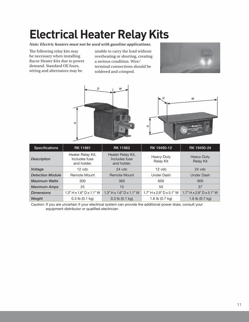
Electrical Heater Relay Kits
Specifications RK 11861 RK 11862 RK 19490-12 RK 19490-24
DescriptionHeater Relay Kit,
Includes fuseand holder.
Heater Relay Kit, Includes fuseand holder.
Heavy-DutyRelay Kit
Heavy-DutyRelay Kit
Voltage 12 vdc 24 vdc 12 vdc 24 vdc
Detection Module Remote Mount Remote Mount Under Dash Under Dash
Maximum Watts 300 360 600 900
Maximum Amps 25 15 50 37
Dimensions 1.3” H x 1.6” D x 1.1” W 1.3” H x 1.6” D x 1.1” W 1.7” H x 2.9” D x 5.1” W 1.7” H x 2.9” D x 5.1” W
Weight 0.3 lb (0.1 kg) 0.3 lb (0.1 kg) 1.6 lb (0.7 kg) 1.6 lb (0.7 kg)
Caution: If you are uncertain if your electrical system can provide the additional power draw, consult your equipment distributor or qualified electrician.
The following relay kits may be necessary when installing Racor Heater Kits due to power demand. Standard OE fuses, wiring and alternators may be
unable to carry the load without overheating or shorting, creating a serious condition. Wire/terminal connections should be soldered and crimped.
Note: Electric heaters must not be used with gasoline applications.
H
D W
H
D W
11

January 2010© 2010 Parker Hannifin Corporation
All products manufactured or distributed by Racor are subject to the following, and only the following, LIMITED EXPRESS WARRANTIES, and no others: For a period of one (1) year from and after the date of purchase of a new Racor product, Racor warrants and guarantees only to the original purchaser-user that such a product shall be free from defects of materials and workmanship in the manufacturing process. The warranty period for pumps and motors is specifically limited to ninety (90) days from date of purchase. A product claimed to be defective must be returned to the place of purchase. Racor, at its sole option, shall replace the defective product with a comparable new product or repair the defective product. This express warranty shall be inapplicable to any product not properly installed and properly used by the purchaser-user or to any product damaged or impaired by external forces.
THIS IS THE EXTENT OF WARRANTIES AVAILABLE ON THIS PRODUCT. RACOR SHALL HAVE NO LIABILITY WHATSOEVER FOR CONSEQUENTIAL DAMAGES
FLOWING FROM THE USE OF ANY DEFECTIVE PRODUCT OR BY REASON OF THE FAILURE OF ANY PRODUCT. RACOR SPECIFICALLY DISAVOWS ALL OTHER WARRANTIES, EXPRESS OR IMPLIED INCLUDING, WITHOUT LIMITATION, ALL WARRANTIES OF FITNESS FOR A PARTICULAR PURPOSE (EXCEPT FOR THOSE WHICH APPLY TO PRODUCT OR PART THEREOF THAT IS USED OR BOUGHT FOR USE PRIMARILY FOR PERSONAL, FAMILY, OR HOUSEHOLD PURPOSES), WARRANTIES OF DESCRIPTION, WARRANTIES OF MERCHANTABILITY, TRADE USAGE OR WARRANTIES OR TRADE USAGE.
Warning
Failure or improper selection or improper use of the products and/or systems described herein or related items can cause death, personal injury and property damage. This document and other information from Parker Hannifin Corporation, its subsidiaries and authorized distributors provide product
and/or system options for further investigation by users having technical expertise. It is important that you analyze all aspects of your application and review the information concerning the product or system in the current product catalog. Due to the variety of operating conditions and applications for these products or systems, the user, through its own analysis and testing, is solely responsible for making the final selection of the products and systems and assuring that all performance, safety and warning requirements of the applications are met. The products described herein, including with limitation, product features, specifications, designs, availability and pricing, are subject to change by Parker Hannifin Corporation and its subsidiaries at any time without notice.
The following statement is required pursuant to proposition 65, applicable in the State of California: ‘This product may contain a chemical known to the State of California to cause cancer or reproductive toxicity’.
Limited Warranties Statement