spiralkegelgetriebe spiral bevel · pdf fileextremely precise with very low backlash and very...
TRANSCRIPT

SpiralkegelgetriebeSpiral Bevel Gearboxes
Tech
nis
che
Dat
en /
Tec
hn
ical
Dat
aje
do
ch n
eust
er S
tan
d u
nte
r /
bu
t, la
test
up
-dat
e :
ww
w.ta
nd
ler.d
e

2
V
I
E
L
F
Ä
L
T
I
G
K
O
M
B
I
N
I
E
R
B
A
R
Alle Baureihen sind auch in Aluminium-Ausführung, korrosionsgeschützt mit vernickelterOberfläche oder mit der werkseigenen Tan-Ox®-Beschichtung lieferbar.
SpiralkegelgetriebeS
PIR
AL
KE
GE
LG
ET
RIE
BE
Seite
4 Ermittlung der Auslegungsdaten
6 Leistungsdaten für Spiralkegelgetriebe außer Schaltgetriebe
8 ... in Standardausführung haben sich durch hohen Wirkungsgrad infolge guter Verzahnungsver- hältnisse und genauer Fertigung bewährt. Sie sind geräuscharm, unempfindlich gegen Stöße, überlastbar und raumsparend.
10 ... mit Hohlwelle (Baureihe HW) werden vor allem im Sondermaschinenbau eingesetzt. Sie eignen sich zum direkten Anschluss von Wellensträngen und sorgen damit für eine Weiterleitung des Drehmo- ments bei geringem Bauraum. Auf Wunsch mit Keil- nabe (Baureihe HWK), Zahnnabe (Baureihe HWZ) oder Schrumpfscheibe (Baureihe HWS) oder auch12 mit Hohlritzel (Baureihe HRZ) erhältlich.
... mit verschiedenen Flansch-Anschlüssen13 (Baureihe F) sind an nahezu alle Drehstrom-Norm- und Servomotoren zu koppeln. Dazu ist das Ritzel als Hohlritzel zur Aufnahme des Motorzapfens ausge- bildet. Für hochdynamische Servo-Anwendungen sollte ein ServoFoxx® Getriebe ausgewählt werden.
... mit extra verstärkter, durchgehender Welle14 (Baureihe WV) dienen zum Aufbau von Hauptwellen- strängen, aus denen nur Teilmomente entnommen werden. Die verwendeten Getriebe sind dadurch wesentlich kleiner und günstiger.
... mit Schaltfunktion zur Drehrichtungsänderung16 (Baureihe S), zum Ein- und Ausschalten der Abtriebswelle (Baureihe AS) und zur schaltbaren Abtriebs-Drehrichtungsänderung in koaxialer Wellen-17 anordnung (Baureihe W).
Räderanordnungen18 • Standard18 • EA - Einwegabzweig-Getriebe19 • ZA - Zweiwegabzeig-Getriebe20 • DA - Dreiwegabzweig-Getriebe
Anordnung der Schalthebel21 • Baureihen S und W22 • Baureihe AS
Technische Daten23 • Definition der Güteklassen23 • Zulässige Radialbelastungen24 • Gewichte24 • Schmierstoffe und Füllmengen25 • Lage der Öl- Ein- und Ablassschrauben26 • Anordnung der Ölschaugläser
27 Bestellbeispiel27 Produktmerkmale
3
Spiral Bevel Gearboxes
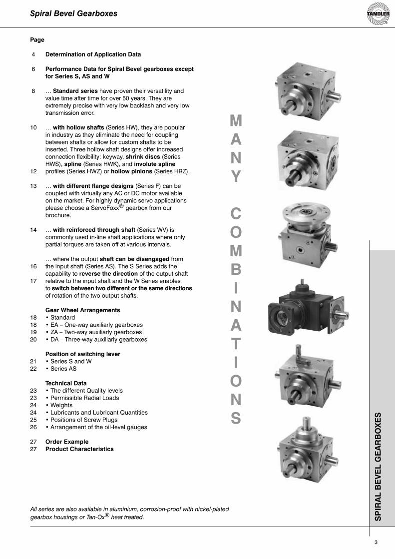
Page
4 Determination of Application Data
6 Performance Data for Spiral Bevel gearboxes except for Series S, AS and W
8 … Standard series have proven their versatility and value time after time for over 50 years. They are extremely precise with very low backlash and very low transmission error.
10 … with hollow shafts (Series HW), they are popular in industry as they eliminate the need for coupling between shafts or allow for custom shafts to be inserted. Three hollow shaft designs offer increased connection flexibility: keyway, shrink discs (Series HWS), spline (Series HWK), and involute spline12 profiles (Series HWZ) or hollow pinions (Series HRZ).
13 … with different flange designs (Series F) can be coupled with virtually any AC or DC motor available on the market. For highly dynamic servo applications please choose a ServoFoxx® gearbox from our brochure.
14 … with reinforced through shaft (Series WV) is commonly used in-line shaft applications where only partial torques are taken off at various intervals.
… where the output shaft can be disengaged from16 the input shaft (Series AS). The S Series adds the capability to reverse the direction of the output shaft17 relative to the input shaft and the W Series enables to switch between two different or the same directions of rotation of the two output shafts.
Gear Wheel Arrangements18 • Standard18 • EA – One-way auxiliarly gearboxes19 • ZA – Two-way auxiliarly gearboxes20 • DA – Three-way auxiliarly gearboxes
Position of switching lever21 • Series S and W22 • Series AS
Technical Data23 • The different Quality levels23 • Permissible Radial Loads24 • Weights24 • Lubricants and Lubricant Quantities25 • Positions of Screw Plugs26 • Arrangement of the oil-level gauges
27 Order Example27 Product Characteristics
All series are also available in aluminium, corrosion-proof with nickel-plated
gearbox housings or Tan-Ox® heat treated.
M
A
N
Y
C
O
M
B
I
N
A
T
I
O
N
S
SP
IRA
L B
EV
EL
GE
AR
BO
XE
S
4
Ermittlung der AuslegungsdatenS
PIR
AL
KE
GE
LG
ET
RIE
BE
Antriebsmaschine (c Faktor)
Stoßgrad dergetrieb. Maschine
ElektromotorLaufzeit in Std. pro Tag
Kolbenmasch., HydromotorLaufzeit in Std. pro Tag
einzylindr. Kolbenmasch.Laufzeit in Std. pro Tag
0,5 3 8 24 0,5 3 8 24 0,5 3 8 24
I 0,5 0,8 1,0 1,25 0,8 1,0 1,25 1,5 1,0 1,25 1,5 1,75
II 0,8 1,0 1,25 1,5 1,0 1,25 1,5 1,75 1,25 1,5 1,75 2,0
III 1,25 1,5 1,75 2,0 1,5 1,75 2,0 2,25 1,75 2,0 2,25 2,5
Leistung P [kW] 1 kW = 1,36 PS Abgangsdrehmoment = M2
Drehmoment M [Nm] 1 Nm = 0,102 kpm Eingangsdrehmoment = M1
Drehzahl n [min-1] 1 min-1 = 0,1047 rad/s Gesamtübersetzung = i
Zul. Radialkraft Fr [N]
M2 = M1 x iM= x ≈ 9.550 x30.000π
Pn
Pn
Betriebsfaktoren für die Getriebeauswahl
Allgemein gilt: i = =
Anmerkung: Es wird stets von einer Übersetzung gesprochen, gleich ob von schnell auf langsam oder langsam auf schnell.
Beispiel: Drehzahl n1 der Welle d1= 1500 min-1
Drehzahl n2 der Welle d2= 750 min-1
i = = = = 2:1
d.h. von n1 aus schnellere auf langsame Drehzahl
Für die Getriebeübersetzung ist im Bestellfall die Festlegung des Herstellers zu beachten, der zur Vermeidung von Irrtümern davon ausgehen muss, dass n1 an der Welle d1 und n2 an der Welle d2 vorliegt.
Bestimmung der Übersetzung
Drehzahl der Welle d1 Drehzahl der Welle d2
n1n2
n1n2
1500 750
21
Sofern man bei der Auslegung an Grenzwerte kommt (z.B. bei der Belastungsart), ist es erforderlich, die Faktoren c (nach Prof. Niemann) zu berücksichtigen.
M2 ist das von der Arbeitsmaschine aufgenommene Nenndrehmoment in Nm,c nach unten stehender Tabelle.
M2 = Drehmoment zum Vergleich mit Tabellen Seite 6 und 7
M2 = M1 x i x c
I Fast stoßfrei, z.B. Stromerzeuger, Förderschnecken, leichte Aufzüge, Elektrozüge, Lüfter, RührwerkeII Mäßige Stöße, z.B. schwere Aufzüge, Krandrehwerke, Kolbenpumpen, Grubenfüller, SeilwindenIII Schwere Stöße, z.B. Stanzen, Scheren, Walzwerks- und Hüttenmaschinen, Kollergänge, Webstühle

5
Determination of Application Data
SP
IRA
L B
EV
EL
GE
AR
BO
XE
S
Power P [kW] 1 kW = 1.36 hp Output torque = M2Torque M [Nm] 1 Nm = 0.102 kpm Input torque = M1Speed n [rpm] rpm = 0.1047 rad/s Total ratio = i
Perm. Radial Load Fr [N]
M2 = M1 x iM= x ≈ 9,550 x30,000π
Pn
Pn
Generally applicable: i = =
Note: The term ratio always applies regardless whether the speed is increasing or reducing.
Example: speed n1 of shaft d1= 1500 min-1
speed n2 of shaft d2= 750 min-1
i = = = = 2:1
i. e. relative to n1, speed reduction
When placing an order, the ratio specified by TANDLER must be observed. In order to avoid errors TANDLER will assume that n1 applies to shaft d1 and n2 applies to shaft d2.
Determination of the ratio
speed of shaft d1 speed of shaft d2
n1n2
n1n2
1500 750
21
Service Factors for the Selection of Gearboxes
If design data indicate that maximum ratings may be reached (e.g. the type of load applied), The „c“ factors (derived from Prof. Niemann) must be included in the calculation.
M2 is the nominal torque in Nm delivered to the driven machine and c isderived from the table below:
M2 = Torque as shown in tables on pages 6 and 7
I allmost shock-free, e.g. electric generators, screw conveyors, lightweight elevators, electric hoists, ventilators, agitatorsII moderate shock, e.g. heavy elevators, crane slewing gear, reciprocating pumps, shaft ventilators, cable hoists.III heavy shock, e.g. punching and cutting machines, machinery used in rolling mills and the steel and iron industry, pug mills, weaving looms.
Main Engine (c Factor)
Degree of shock of driven machine
Electric motorRunning time in h per day
Piston motor, hydraulic motorRunning time in h per day
Single-cylinder piston motorRunning time in h per day
0,5 3 8 24 0,5 3 8 24 0,5 3 8 24
I 0,5 0,8 1,0 1,25 0,8 1,0 1,25 1,5 1,0 1,25 1,5 1,75
II 0,8 1,0 1,25 1,5 1,0 1,25 1,5 1,75 1,25 1,5 1,75 2,0
III 1,25 1,5 1,75 2,0 1,5 1,75 2,0 2,25 1,75 2,0 2,25 2,5
M2 = M1 x i x c

6
Leistungsdaten für Spiralkegelgetriebe (außer Schaltgetriebe)
Zulässige Drehmomente am Abtrieb der Welle d2
SP
IRA
LK
EG
EL
GE
TR
IEB
E
Standardlagerung:mit verstärkter Lagerung (S 522/S 523):
standard bearingsreinforced bearings (S 522/S 523)
i = n1:n2 = 1:1 i = n1:n2 = 1,25:1 bis/ up to 1,5:1
i = n1:n2 = 1,75:1 bis/ up to 3:1 i = n1:n2 = 3,5:1 bis/ up to 4:1
Drehzahl / Speed n1 [min-1] Drehzahl / Speed n1 [min-1]
Drehzahl / Speed n1 [min-1] Drehzahl / Speed n1 [min-1]
Dre
hm
om
ent
/ To
rqu
e M
2 [N
m]
Dre
hm
om
ent
/ To
rqu
e M
2 [N
m]
Dre
hm
om
ent
/ To
rqu
e M
2 [N
m]
Dre
hm
om
ent
/ To
rqu
e M
2 [N
m]
7
SP
IRA
L B
EV
EL
GE
AR
BO
XE
S
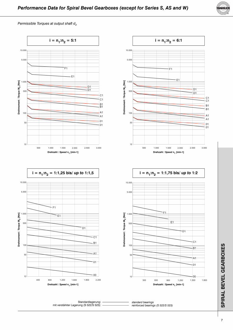
Performance Data for Spiral Bevel Gearboxes (except for Series S, AS and W)
Standardlagerung:mit verstärkter Lagerung (S 522/S 523):
standard bearingsreinforced bearings (S 522/S 523)
i = n1:n2 = 5:1 i = n1:n2 = 6:1
i = n1:n2 = 1:1,25 bis/ up to 1:1,5 i = n1:n2 = 1:1,75 bis/ up to 1:2
Permissible Torques at output shaft d2
Drehzahl / Speed n1 [min-1] Drehzahl / Speed n1 [min-1]
Drehzahl / Speed n1 [min-1] Drehzahl / Speed n1 [min-1]
Dre
hm
om
ent
/ To
rqu
e M
2 [N
m]
Dre
hm
om
ent
/ To
rqu
e M
2 [N
m]
Dre
hm
om
ent
/ To
rqu
e M
2 [N
m]
Dre
hm
om
ent
/ To
rqu
e M
2 [N
m]
8
SP
IRA
LK
EG
EL
GE
TR
IEB
E B
AU
RE
IHE
STA
ND
AR
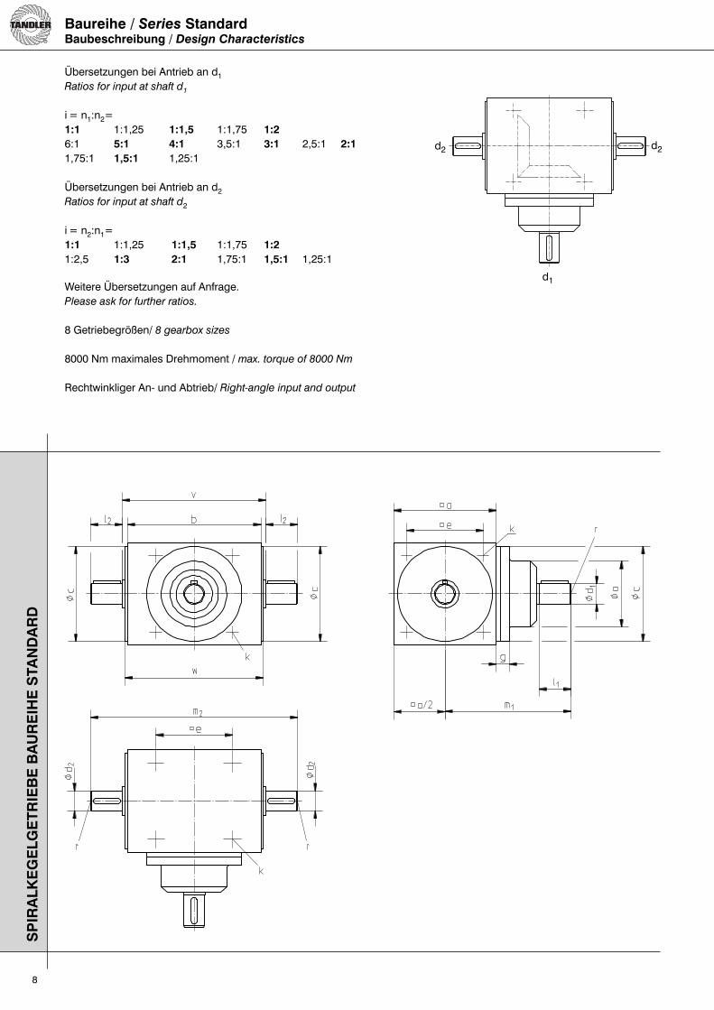
DBaureihe / Series StandardBaubeschreibung / Design Characteristics
Übersetzungen bei Antrieb an d1Ratios for input at shaft d1
i = n1:n2= 1:1 1:1,25 1:1,5 1:1,75 1:26:1 5:1 4:1 3,5:1 3:1 2,5:1 2:11,75:1 1,5:1 1,25:1
Übersetzungen bei Antrieb an d2Ratios for input at shaft d2
i = n2:n1= 1:1 1:1,25 1:1,5 1:1,75 1:21:2,5 1:3 2:1 1,75:1 1,5:1 1,25:1
Weitere Übersetzungen auf Anfrage.Please ask for further ratios.
8 Getriebegrößen/ 8 gearbox sizes
8000 Nm maximales Drehmoment / max. torque of 8000 Nm
Rechtwinkliger An- und Abtrieb/ Right-angle input and output
d1
d2 d2

9
Abmessungen / Dimensions
SP
IRA
L B
EV
EL
GE
AR
BO
XE
S S
ER
IES
STA
ND
AR
D
Verdrehspiel an Welle d2 / Backlash at shaft d2
Größe / Gearbox Size 00 - B1 C1 - F1Standard-Ausführung 6‘ 7‘Standard Design [arc min.] 6‘ 7‘Eingeengtes Verdrehspiel 4‘ 4‘Minimal Backlash [arc min.] 4‘ 4‘Abhängig vom Einsatzfall ist auch 1‘ möglich. Depending on the application 1 arc minute may also be possible.
Übersetzung/Ratio i=n1 : n2Getriebe-größe
Gearboxsize
Allgemein (außer 1:1,75 und 1:2) / In General (exept 1:1,75 and 1:2) d2
a b cj7 ek
Tiefe/depth =1,5•k
I2 m2 v w d2j6 r Paßf./KeyDIN6885
00 80 110 74 60 M 6 30 177 117 115 14 M 6 5 x 501 110 145 102 82 M 8 35 222 152 150 22 M 8 6 x 6A1 140 175 130 105 M10 45 274 184 182 32 M10 10 x 8B1 170 215 160 130 M12 60 344 224 222 42 M12 12 x 8C1 210 260 195 160 M16 85 440 270 268 55 M16 16 x 10D1 260 330 245 200 M16 100 540 340 338 65 M16 18 x 11E1 330 430 310 260 M20 120 680 440 438 75 M20 20 x 12F1 400 530 380 320 M24 150 840 540 538 90 M24 25 x 14
Getriebe-größe
Gearboxsize
1:1; 1,25:1; 1,5:1; 1,75:1; 2:1; 2,5:1; 1:1,25; 1:1,15
d1
g I1 m1 o d1j6 r Paßf./KeyDIN 6885
00 13 30 110 52 14 M 6 5x 501 14 35 135 70 22 M 8 6x 6A1 14 45 165 90 32 M10 10x 8B1 18 60 210 110 42 M12 12x 8C1 18 85 275 135 55 M16 16x10D1 23 100 340 150 65 M16 18x11E1 29 120 435 230 75 M20 20x12F1 40 150 550 270 90 M24 25x14
Getriebe-größe
Gearboxsize
3:1 d1
g I1 m1 o d1j6 r Paßf./KeyDIN 6885
00 13 25 105 52 12 M 5 4x 401 14 35 135 70 22 M 8 6x 6A1 14 45 165 90 32 M10 10x 8B1 18 55 205 100 36 M10 10x 8C1 18 65 255 135 38 M10 10x 8D1 23 85 325 135 55 M16 16x10E1 29 85 400 190 55 M16 16x10F1 40 120 520 270 75 M20 20x12
Getriebe-größe
Gearboxsize
3,5:1 d1
g I1 m1 o d1j6 r Paßf./KeyDIN 6885
00 13 25 105 52 12 M 5 4x 401 14 30 130 70 16 M 6 5x 5A1 14 32 152 80 20 M 8 6x 6B1 23 45 200 80 26 M 8 8x 7C1 18 45 235 105 32 M10 10x 8D1 28 70 310 110 42 M12 12x 8E1 29 75 390 190 50 M16 14x 9F1 40 95 495 200 60 M16 18x11
Getriebe-größe
Gearboxsize
4:1 d1
g I1 m1 o d1j6 r Paßf./KeyDIN 6885
00 13 20 100 47 9 M 4 3x 301 14 30 130 70 16 M 6 5x 5A1 14 32 152 80 20 M 8 6x 6B1 23 45 200 80 26 M 8 8x 7C1 18 45 235 105 32 M10 10x 8D1 28 70 310 110 42 M12 12x 8E1 29 75 390 190 50 M16 14x 9F1 40 95 495 200 60 M16 18x11
Getriebe-größe
Gearboxsize
5:1 d1
g I1 m1 o d1j6 r Paßf./KeyDIN 6885
00 - - - - - - -01 14 22 122 55 12 M 5 4x 4A1 14 30 150 65 16 M 6 5x 5B1 24 40 195 70 22 M 8 6x 6C1 18 45 235 95 26 M 8 8x 7D1 23 58 298 105 32 M10 10x 8E1 29 70 385 190 42 M12 12x 8F1 40 85 485 200 55 M16 16x10
Getriebe-größe
Gearboxsize
6:1 d1
g I1 m1 o d1j6 r Paßf./KeyDIN 6885
00 - - - - - - -01 14 22 122 50 10 M 4 3x 3A1 14 30 150 55 12 M 5 4x 4B1 24 30 185 70 16 M 6 5x 5C1 18 40 230 95 20 M 8 6x 6D1 23 45 285 105 26 M 8 8x 7E1 29 70 385 190 40 M12 12x 8F1 40 85 485 200 55 M16 16x10
Getriebe-größe
Gearboxsize
1:1,75 und/and 1:2 d1 d2
a b cj7 e g hk
Tiefe/depth=1,5•k
l1 l2 m1 m2 o v d1j6 r Paßf./KeyDIN6885
d2j6 r Paßf./Key
DIN6885
00 80 110 74 60 13 40 M 6 30 25 110 167 52 117 14 M 6 5x 5 12 M 5 4x 401 110 145 102 82 14 45 M 8 35 30 135 212 70 152 22 M 8 6x 6 16 M 6 5x 5A1 140 175 130 105 14 50 M10 45 42 165 268 90 184 32 M10 10x 8 24 M 8 8x 7B1 170 215 160 130 18 65 M12 60 50 210 324 110 224 42 M12 12x 8 28 M 8 8x 7C1 210 260 195 160 18 85 M16 85 60 275 390 135 270 55 M16 16x 10 38 M12 10x 8D1 260 330 245 200 23 110 M16 100 80 340 500 150 340 65 M16 18x 11 50 M16 14x 9E1 330 430 310 260 29 150 M20 120 90 435 620 230 440 75 M20 20x 12 50 M16 14x 9F1 400 530 380 320 40 200 M24 150 130 550 800 270 540 90 M24 25x 14 65 M16 18x 11
Die fettmarkierten „marktgängigen“ Getriebe haben gegenüber anderen Getrieben einen Liefertermin-Vorteil.The bold-marked "preferred" gearboxes may be delivered
quicker than other gearboxes.
10
SP
IRA
LK
EG
EL
GE
TR
IEB
E B
AU
RE
IHE
N H
W, H
WS
, HW
K, H
WZ
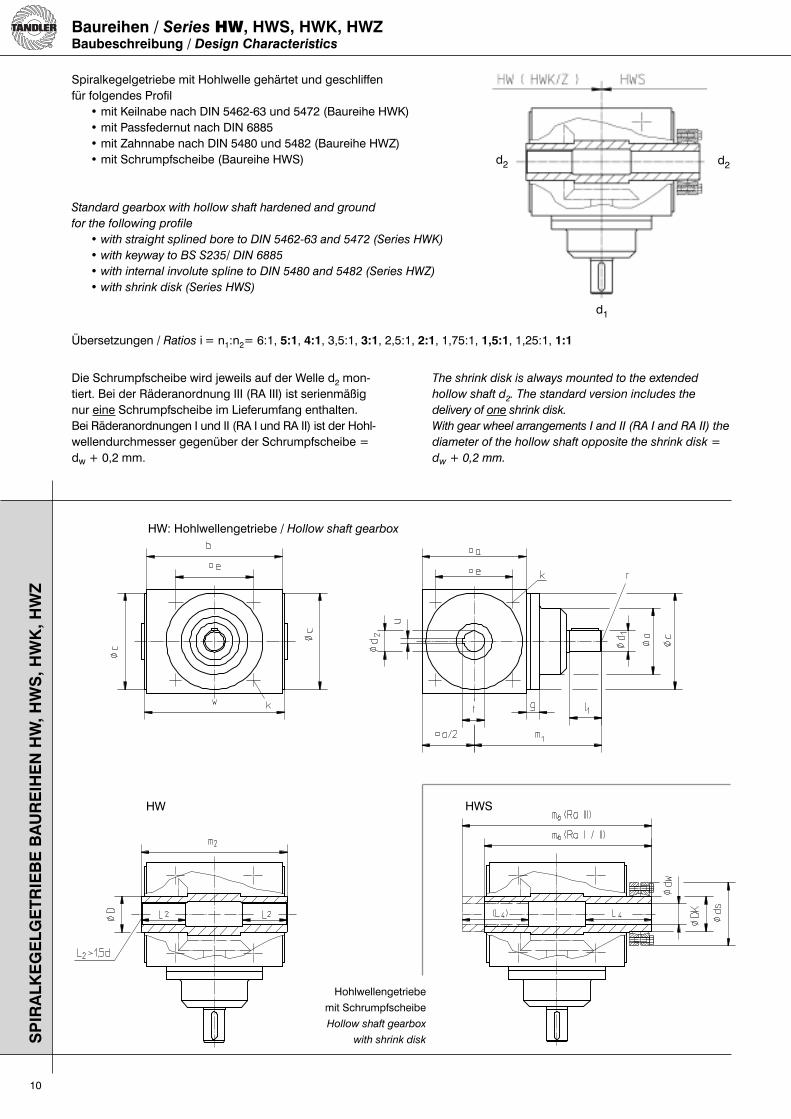
Spiralkegelgetriebe mit Hohlwelle gehärtet und geschliffenfür folgendes Profil• mit Keilnabe nach DIN 5462-63 und 5472 (Baureihe HWK)• mit Passfedernut nach DIN 6885• mit Zahnnabe nach DIN 5480 und 5482 (Baureihe HWZ)• mit Schrumpfscheibe (Baureihe HWS)
Standard gearbox with hollow shaft hardened and ground
for the following profile
• with straight splined bore to DIN 5462-63 and 5472 (Series HWK)
• with keyway to BS S235/ DIN 6885
• with internal involute spline to DIN 5480 and 5482 (Series HWZ)
• with shrink disk (Series HWS)
Baureihen / Series HW, HWS, HWK, HWZBaubeschreibung / Design Characteristics
Die Schrumpfscheibe wird jeweils auf der Welle d2 mon-tiert. Bei der Räderanordnung III (RA III) ist serienmäßig nur eine Schrumpfscheibe im Lieferumfang enthalten. Bei Räderanordnungen I und II (RA I und RA II) ist der Hohl-wellendurchmesser gegenüber der Schrumpfscheibe = dw + 0,2 mm.
The shrink disk is always mounted to the extended
hollow shaft d2. The standard version includes the
delivery of one shrink disk.
With gear wheel arrangements I and II (RA I and RA II) the
diameter of the hollow shaft opposite the shrink disk =
dw + 0,2 mm.
Hohlwellengetriebe
mit Schrumpfscheibe
Hollow shaft gearbox
with shrink disk
d1
d2 d2
HW: Hohlwellengetriebe / Hollow shaft gearbox
HW HWS
Übersetzungen / Ratios i = n1:n2= 6:1, 5:1, 4:1, 3,5:1, 3:1, 2,5:1, 2:1, 1,75:1, 1,5:1, 1,25:1, 1:1
11
SP
IRA
L B
EV
EL
GE
AR
BO
XE
S S
ER
IES
HW
, HW
S, H
WK
, HW
Z
Abmessungen / Dimensions
Übersetzung/Ratio i=n1 : n2
Getriebe-größe
GearboxSize
1:1; 1,25:1; 1,5:1; 1,75:1;2:1; 2,5:1
d1
g I1 m1 o d1j6 r Paßf./KeyDIN 6885
HW 00 13 30 110 52 14 M 6 5x 5HW 01 14 35 135 70 22 M 8 6x 6HW A1 14 45 165 90 32 M10 10x 8HW B1 18 60 210 110 42 M12 12x 8HW C1 18 85 275 135 55 M16 16x10HW D1 23 100 340 150 65 M16 18x11HW E1 29 120 435 230 75 M20 20x12HW F1 40 150 550 270 90 M24 25x14
Getriebe-größe
GearboxSize
3:1d1
g I1 m1 o d1j6 r Paßf./KeyDIN 6885
HW 00 13 25 105 52 12 M 5 4x 4HW 01 14 35 135 70 22 M 8 6x 6HW A1 14 45 165 90 32 M10 10x 8HW B1 18 55 205 100 36 M12 10x 8HW C1 18 65 255 135 38 M12 10x 8HW D1 23 85 325 135 55 M16 16x10HW E1 29 85 400 190 55 M16 16x10HW F1 40 120 520 270 75 M20 20x12
Getriebe-größe
GearboxSize
3,5:1 d1
g I1 m1 o d1j6 r Paßf./KeyDIN 6885
HW 00 13 25 105 52 12 M 5 4x 4HW 01 14 30 130 70 16 M 6 5x 5HW A1 14 32 152 80 20 M 8 6x 6HW B1 23 45 200 80 26 M 8 8x 7HW C1 18 45 235 105 32 M10 10x 8HW D1 28 70 310 110 42 M12 12x 8HW E1 29 75 390 190 50 M16 14x 9HW F1 40 95 495 200 60 M16 18x11
Getriebe-größe
Gearbox Size
4:1 d1
g I1 m1 o d1j6 r Paßf./KeyDIN 6885
HW 00 13 20 100 47 9 M 4 3x 3HW 01 14 30 130 70 16 M 6 5x 5HW A1 14 32 152 80 20 M 8 6x 6HW B1 23 45 200 80 26 M 8 8x 7HW C1 18 45 235 105 32 M10 10x 8HW D1 28 70 310 110 42 M12 12x 8HW E1 29 75 390 190 50 M16 14x 9HW F1 40 95 495 200 60 M16 18x11
Getriebe-größe
GearboxSize
5:1 d1
g I1 m1 o d1j6 r Paßf./KeyDIN 6885
HW 00 - - - - - - -HW 01 14 22 122 55 12 M 5 4x 4HW A1 14 30 150 65 16 M 6 5x 5HW B1 24 40 195 70 22 M 8 6x 6HW C1 18 45 235 95 26 M 8 8x 7HW D1 23 58 298 105 32 M10 10x 8HW E1 29 70 385 190 42 M12 12x 8HW F1 40 85 485 200 55 M16 16x10
Getriebe-größe
GearboxSize
6:1 d1
g I1 m1 o d1j6 r Paßf./KeyDIN 6885
HW 00 - - - - - - -HW 01 14 22 122 50 10 M 4 3x 3HW A1 14 30 150 55 12 M 5 4x 4HW B1 24 30 185 70 16 M 6 5x 5HW C1 18 40 230 95 20 M 8 6x 6HW D1 23 45 285 105 26 M 8 8x 7HW E1 29 70 385 190 40 M10 12x 8HW F1 - - - - - - -
Verdrehspiel an Welle d2 / Backlash at shaft d2
Größe / Gearbox Size 00 - B1 C1 - F1Standard-Ausführung 6‘ 7‘Standard Design [arc min.] 6‘ 7‘Eingeengtes Verdrehspiel 4‘ 4‘Minimal Backlash [arc min.] 4‘ 4‘Abhängig vom Einsatzfall ist auch 1‘ möglich. Depending on the application 1 arc minute may also be possible.
Getriebe-größe
Gearboxsize
Allgemein / In Generald2
HW HWK HWZ HWS
a b cj7 e
kTiefe Depth
=1,5.k
m2 t uJ9 v w D d2H7
Paßf./Key
DIN 6885 BI.3
DIN
Keilnaben/straight
splined
bore
Keile/Spline
Zahnna-benprofil/internal
involute
spline DIN 5482
DK ds dwH6 L4 m6
RA I,II
m6
RA III
HW 00 80 110 74 60 M 6 117 15,2 5 117 115 22 14 5x 3 - - - - 18 44 14 28 133,5 150
HW 01 110 145 102 82 M 8 152 23,6 6 152 150 38 22 6x 4 5463 21x25x5 6 A25x22 30 60 24 60 178,0 204
HW A1 140 175 130 105 M10 184 30,0 8 184 182 42 28 8x 5 5462 28x32x7 6 A30x27 36 72 28 70 212,5 241
HW B1 170 215 160 130 M12 224 37,4 10 224 222 55 35 10x 6 5472 36x42x8 6 A40x36 44 80 35 80 254,5 285
HW C1 210 260 195 160 M16 270 47,1 14 270 268 65 45 14x 6 5472 42x48x10 6 A50x45 55 100 45 90 305,0 340
HW D1 260 330 245 200 M16 340 57,4 16 340 338 80 55 16x 7 5463 46x54x9 8 A60x55 75 138 55 120 380,0 420
HW E1 330 430 310 260 M20 440 64,4 18 440 438 100 60 18x11 5472 58x65x14 6 A65x60 85 155 65 150 486,0 532
HW F1 400 530 380 320 M24 540 74,7 20 540 538 120 70 20x12 5472 68x78x16 6 A75x69 100 170 70 180 591,0 642
Die fettmarkierten „marktgängigen“ Getriebe haben gegenüber anderen Getrieben einen Liefertermin-Vorteil.The bold-marked "preferred" gearboxes may be delivered
quicker than other gearboxes.
12
SP
IRA
LK
EG
EL
GE
TR
IEB
E B
AU
RE
IHE
HR
Z
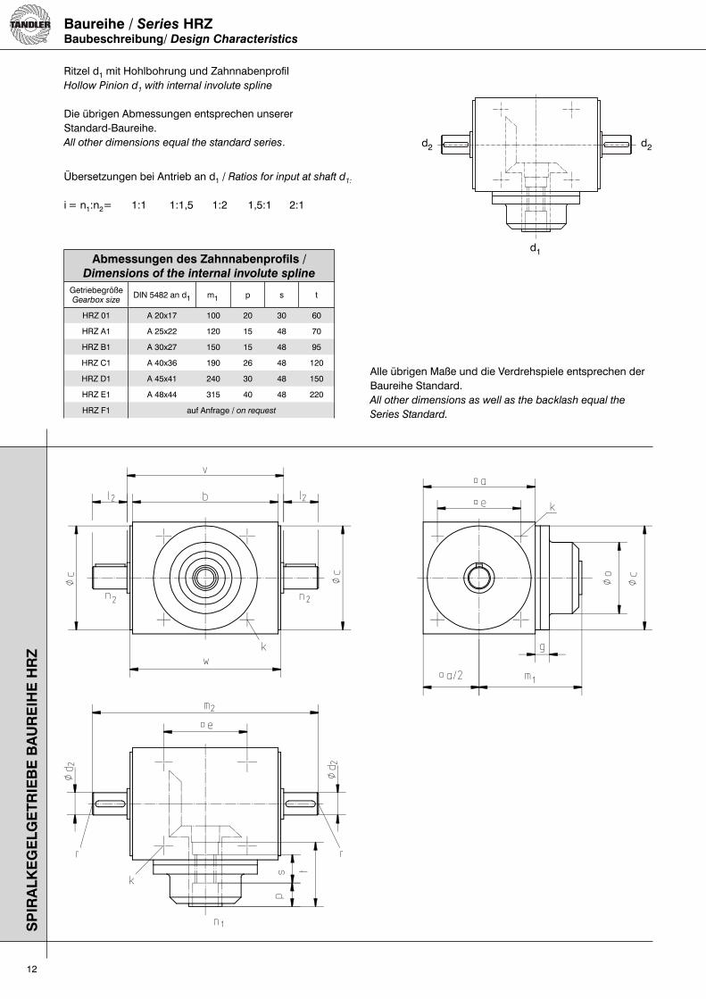
Ritzel d1 mit Hohlbohrung und ZahnnabenprofilHollow Pinion d1 with internal involute spline
Die übrigen Abmessungen entsprechen unsererStandard-Baureihe.All other dimensions equal the standard series.
Baureihe / Series HRZBaubeschreibung/ Design Characteristics
Übersetzungen bei Antrieb an d1 / Ratios for input at shaft d1:
i = n1:n2= 1:1 1:1,5 1:2 1,5:1 2:1
Abmessungen des Zahnnabenprofils /Dimensions of the internal involute spline
GetriebegrößeGearbox size
DIN 5482 an d1 m1 p s t
HRZ 01 A 20x17 100 20 30 60
HRZ A1 A 25x22 120 15 48 70
HRZ B1 A 30x27 150 15 48 95
HRZ C1 A 40x36 190 26 48 120
HRZ D1 A 45x41 240 30 48 150
HRZ E1 A 48x44 315 40 48 220
HRZ F1 auf Anfrage / on request
d2
d1
d2
Alle übrigen Maße und die Verdrehspiele entsprechen der Baureihe Standard.All other dimensions as well as the backlash equal the
Series Standard.

13
SP
IRA
LK
EG
EL
GE
TR
IEB
E B
AU
RE
IHE
F
Standardgetriebe mit Hohlritzel mit Nut und Motorflansch an d1Standard gearbox with hollow pinion with keyway and flange at d1
Baureihe / Series FBaubeschreibung / Design Characteristics
Abmessungen / Dimensions
GetriebegrößeGearbox size
Flansch (DIN 42677) / Flange (DIN 42677)Standardausführung / Standard Version
d1
b1H7 l1 Lkr m1 o S1 t uJ9 d1
H7 Paßf./KeyDIN 6885
F 00 110 30 130 92 160 9 16,3 5 14 5x 5
F 01 110 40 130 128 160 9 21,8 6 19 6x 6
F A1 130 60 165 150 200 11 31,3 8 28 8x 7
F B1 130 60 165 177 200 11 31,3 8 28 8x 7
F C1 230 80 265 197 300 13,5 41,3 10 38 10x 8
F D1 250 110 300 245 350 18,5 51,8 14 48 14x 9
Übersetzungen/Ratios i = n1:n2= 1:1; 1,25:1; 1,5:1; 1,75:1; 2:1; 2,5:1; 3:1; 3,5:1; 4:1; 5:1; 1:1,25; 1:1,5; 1:1,75; 1:2
GetriebegrößeGearbox size
d2
a b cj7 e g hk
Tiefe/Depth =1,5.kI2 m2 v w d2j6 r
Paßf./KeyDIN 6885
F 00 80 110 74 60 10 52 M 6 30 177 117 115 14 M 6 5x 5
F 01 110 145 102 82 18 73 M 8 35 222 152 150 22 M 8 6x 6
F A1 140 175 130 105 19 80 M10 45 274 184 182 32 M 10 10x 8
F B1 170 215 160 130 24 92 M12 60 344 224 222 42 M 12 12x 8
F C1 210 260 195 160 22 92 M16 85 440 270 268 55 M 16 16x10
F D1 260 330 245 200 25 115 M16 100 540 340 338 65 M 16 18x11
Weitere Flanschdurchmesser möglich. / Further flange diameters available.
Verdrehspiele siehe Seite 11. / Backlash on page 11.
d2
d2

14
SP
IRA
LK
EG
EL
GE
TR
IEB
E B
AU
RE
IHE
WV
Spiralkegelgetriebe mit verstärkter Welle an d2Spiral-bevel gearbox with reinforced shaft at d2
Übersetzung / Ratio i = n1:n2= 1:1; 1,25:1; 1,5:1; 1,75:1; 2:12,5:1; 3:1; 3,5:1, 4:1; 5:1; 6:1
Baureihe / Series WVBaubeschreibung / Design Characteristics
Zulässige Drehmomente zum Durchleiten durchdie verstärkte Welle d2
Permissible Torques for the transmission trough
the reinforced shaft d2
GetriebegrößeGearbox Size
d2j6 M2 zul.
WV 00 20 80 Nm
WV 01 35 380 Nm
WV A1 40 580 Nm
WV B1 50 1150 Nm
WV C1 60 1950 Nm
WV D1 75 3900 Nm
WV E1 85 5800 Nm
WV F1 100 9000 Nm
d2 d2
d1
gezeichnet Räderanordnung III (RA III)
Gear wheel arrangement III (RA III)

15
SP
IRA
L B
EV
EL
GE
AR
BO
XE
S S
ER
IES
WV
Abmessungen / Dimensions
Getriebe-größe
GearboxSize
1:1; 1,25:1; 1,5:1; 1,75:1; 2:1; 2,5:1 d1
g I1 m1 o d1j6 r Paßf./KeyDIN 6885
WV 00 13 30 110 52 14 M 6 5 x 5
WV 01 14 35 135 70 22 M 8 6 x 6
WV A1 14 45 165 90 32 M10 10x 8
WV B1 18 60 210 110 42 M12 12x 8
WV C1 18 85 275 135 55 M16 16x10
WV D1 23 100 340 150 65 M16 18x11
WV E1 29 120 435 230 75 M20 20x12
WV F1 40 150 550 270 90 M24 25x14
Getriebe-größe
GearboxSize
3:1 d1
g I1 m1 o d1j6 r Paßf./KeyDIN 6885
WV 00 13 25 105 52 12 M 5 4x 4
WV 01 14 35 135 70 22 M 8 6x 6
WV A1 14 45 165 90 32 M10 10x 8
WV B1 18 55 205 100 36 M12 10x 8
WV C1 18 65 255 135 38 M12 10x 8
WV D1 23 85 325 135 55 M16 16x10
WV E1 29 85 400 190 55 M16 16x10
WV F1 40 120 520 270 75 M20 20x12
Getriebe-größe
GearboxSize
3,5:1 d1
g I1 m1 o d1j6 rPaßf./KeyDIN 6885
WV 00 13 25 105 52 12 M 5 4x 4
WV 01 14 30 130 70 16 M 6 5x 5
WV A1 14 32 152 80 20 M 8 6x 6
WV B1 23 45 200 80 26 M 8 8x 7
WV C1 18 45 235 105 32 M10 10x 8
WV D1 28 70 310 110 42 M12 12x 8
WV E1 29 75 390 190 50 M16 14x 9
WV F1 40 95 495 200 60 M16 18x11
Getriebe-größe
GearboxSize
4:1 d1
g I1 m1 o d1j6 rPaßf./KeyDIN 6885
WV 00 13 20 100 47 9 M 4 3x 3
WV 01 14 30 130 70 16 M 6 5x 5
WV A1 14 32 152 80 20 M 8 6x 6
WV B1 23 45 200 80 26 M 8 8x 7
WV C1 18 45 235 105 32 M10 10x 8
WV D1 28 70 310 110 42 M12 12x 8
WV E1 29 75 390 190 50 M16 14x 9
WV F1 40 95 495 200 60 M16 18x11
Getriebe-größe
GearboxSize
5:1 d1
g I1 m1 o d1j6 rPaßf./KeyDIN 6885
WV 00 - - - - - - -
WV 01 14 22 122 55 12 M 5 4x 4
WV A1 14 30 150 65 16 M 6 5x 5
WV B1 24 40 195 70 22 M 8 6x 6
WV C1 18 45 235 95 26 M 8 8x 7
WV D1 23 58 298 105 32 M10 10x 8
WV E1 29 70 385 190 42 M12 12x 8
WV F1 40 85 485 200 55 M16 16x10
Übersetzung/Ratio i=n1 : n2
Getriebe-größe
GearboxSize
6:1 d1
g I1 m1 o d1j6 rPaßf./KeyDIN 6885
WV 00 - - - - - - -
WV 01 14 22 122 50 10 M 4 3x 3
WV A1 14 30 150 55 12 M 5 4x 4
WV B1 24 30 185 70 16 M 6 5x 5
WV C1 18 40 230 95 20 M 8 6x 6
WV D1 23 45 285 105 26 M 8 8x 7
WV E1 29 70 385 190 40 M10 12x8
WV F1 - - - - - - -
Allgemein/In General d2GetriebegrößeGearbox Size a b cj7 e
kTiefe/Depth =1,5.k
l2 m2 v w d2j6 rPaßf./KeyDIN 6885
WV 00 80 110 74 60 M 6 35 187 117 115 20 M 8 6x 6
WV 01 110 145 102 82 M 8 55 262 152 150 35 M10 10x 8
WV A1 140 175 130 105 M10 65 314 184 182 40 M12 12x 8
WV B1 170 215 160 130 M12 80 384 224 222 50 M16 14x 9
WV C1 210 260 195 160 M16 95 460 270 268 60 M16 18x11
WV D1 260 330 245 200 M16 115 570 340 338 75 M20 20x12
WV E1 330 430 310 260 M20 130 700 440 438 85 M20 22x14
WV F1 400 530 380 320 M24 160 860 540 538 100 M24 28x16
Verdrehspiel an Welle d2 / Backlash at shaft d2
Größe / Gearbox Size 00 - B1 C1 - F1Standard-Ausführung 6‘ 7‘Standard Design [arc min.] 6‘ 7‘Eingeengtes Verdrehspiel 4‘ 4‘Minimal Backlash [arc min.] 4‘ 4‘Abhängig vom Einsatzfall ist auch 1‘ möglich. Depending on the application 1 arc minute may also be possible.
Die fettmarkierten „marktgängigen“ Getriebe haben gegenüber anderen Getrieben einen Liefertermin-Vorteil.The bold-marked "preferred" gearboxes may be delivered
quicker than other gearboxes.

16
SP
IRA
LK
EG
EL
GE
TR
IEB
E B
AU
RE
IHE
S U
ND
AS
Baureihe / Series S und / and ASBaubeschreibung / Design Characteristics
Übersetzung / Ratio
i = n1:n2 = 1:1; 1,25:1; 1,5:1; 2:1Baureihe AS bis 3:1 / Series AS up to 3:1
Räderanordnungen (RA) I und III möglichGear wheel arrangements (RA) I and III possible
Die Anordnung der Schalthebel ist auf den Seiten 21 und 22 erläutert.For the position of the switching lever,
please refer to pages 21 and 22.
Abmessungen / Dimensions
Verdrehflankenspiel siehe Seite 17Backlash on page 17
Getriebe-größe
GearboxSize
Übersetzungen / Ratios i = n1:n2 = 1:1; 1,25:1; 1,5:1; 2:1 d1 d2
a b cj7 e gk
Tiefe/Depth
1,5.k
l1l2
m1 m2 n o p v wd1j6d2j6
rPaßf./KeyDIN 6885
Schaltwinkelswitch angle
S/AS 01 110 145 102 82 14 M 8 35 135 222 65 70 255 152 150 22 M 8 6x 670°
bis/up to80° von
0-Stellung/from0-position
S/AS A1 140 175 130 105 14 M10 45 165 274 65 90 300 184 182 32 M10 10x 8
S/AS B1 170 215 160 130 18 M12 60 210 344 80 110 375 224 222 42 M12 12x 8
S/AS C1 210 260 195 160 18 M16 85 275 440 80 135 460 270 268 55 M16 16x10
S/AS D1 260 330 245 200 23 M16 100 340 540 80 150 550 340 338 65 M16 18x11
S/AS E1 330 430 310 260 29 M20 120 435 680 80 230 680 440 438 75 M20 20x12
Dre
hm
om
ent
/ To
rqu
e M
2 [N
m]
Drehzahl / Speed n1 [min-1]
Schaltgetriebe
Switch Unit
Ausschaltgetriebe
Switch-off Unit
Losräder /loose wheel
0-Stellung /0-Position
Losräder /loose wheel
0-Stellung /0-Position
Die fettmarkierten „marktgängigen“ Getriebe haben gegenüber anderen Getrieben einen Liefertermin-Vorteil.The bold-marked "preferred" gearboxes may be delivered
quicker than other gearboxes.
d2 d2
d1
d2 d2
d1
17
SP
IRA
LK
EG
EL
GE
TR
IEB
E B
AU
RE
IHE
W
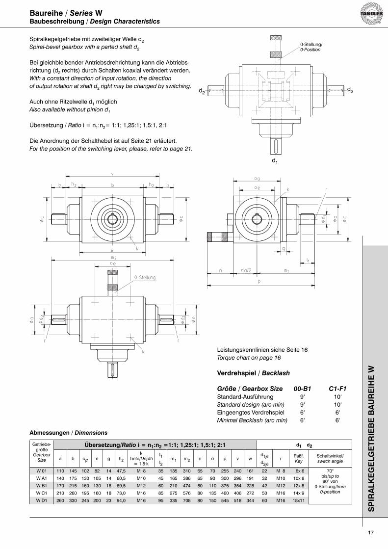
Baureihe / Series WBaubeschreibung / Design Characteristics
Spiralkegelgetriebe mit zweiteiliger Welle d2Spiral-bevel gearbox with a parted shaft d2
Bei gleichbleibender Antriebsdrehrichtung kann die Abtriebs-richtung (d2 rechts) durch Schalten koaxial verändert werden.With a constant direction of input rotation, the direction
of output rotation at shaft d2 right may be changed by switching.
Auch ohne Ritzelwelle d1 möglichAlso available without pinion d1
Übersetzung / Ratio i = n1:n2= 1:1; 1,25:1; 1,5:1, 2:1
Die Anordnung der Schalthebel ist auf Seite 21 erläutert.For the position of the switching lever, please, refer to page 21.
Abmessungen / Dimensions
Getriebe-größe
GearboxSize
Übersetzung/Ratio i = n1:n2 =1:1; 1,25:1; 1,5:1; 2:1 d1 d2
a b cj7 e g h2
kTiefe/Depth = 1,5.k
l1l2
m1 m2 n o p v wd1j6d2j6
rPaßf.Key
Schaltwinkel/switch angle
W 01 110 145 102 82 14 47,5 M 8 35 135 310 65 70 255 240 161 22 M 8 6x 6 70°bis/up to80° von
0-Stellung/from0-position
W A1 140 175 130 105 14 60,5 M10 45 165 386 65 90 300 296 191 32 M10 10x 8
W B1 170 215 160 130 18 69,5 M12 60 210 474 80 110 375 354 228 42 M12 12x 8
W C1 210 260 195 160 18 73,0 M16 85 275 576 80 135 460 406 272 50 M16 14x 9
W D1 260 330 245 200 23 94,0 M16 95 335 708 80 150 545 518 344 60 M16 18x11
Leistungskennlinien siehe Seite 16Torque chart on page 16
Verdrehspiel / Backlash
Größe / Gearbox Size 00-B1 C1-F1
Standard-Ausführung 9‘ 10‘Standard design (arc min) 9‘ 10‘Eingeengtes Verdrehspiel 6‘ 6‘Minimal Backlash (arc min) 6‘ 6‘
0-Stellung/0-Position
d2d2
d1

18
Räderanordnungen / Gear Wheel Arrangements (RA)S
PIR
AL
KE
GE
LG
ET
RIE
BE
Standard
Einweg-Abzweig-Getriebe (EA) / One-way auxiliary gearbox (EA)
Getriebe mit einem oder zwei Wellenzapfen d2 / Gearbox with one or two shafts d2
Gilt für alle Übersetzungen / Valid for all ratios.
Getriebe mit zusätzlichem Abtriebszapfen d5 / Gearbox with additional output shaft d5
Es gilt immer / Fixed Ratio: i= n1:n5 = 1:1
Gilt für alle Übersetzungen / Valid for all ratios.
Die Angabe der Drehrichtung erfolgt immer bei Ansicht der Stirnseite des Wellenzapfens.Please, always refer to the direction of rotation when looking onto the shaft head.
I II III
IV = II V = I VI = III
EA-I EA-II EA-III
EA-IV = EA-II EA-V = EA-I EA-VI = EA-III
d2
d1
d5
d2
d2
d2
d1

19
Räderanordnungen / Gear Wheel Arrangements (RA)Zweiweg-Abzweig-Getriebe (ZA) / Two-way auxiliary gearboxes (ZA)
SP
IRA
LK
EG
EL
GE
TR
IEB
E
Standardgetriebe mit zusätzlichen Abtriebszapfen d3 bzw. d4 oder d3 + d4Standard gearbox with additional output shafts d3 or d4 or d3 + d4
Übersetzung i = n1:n2 = 1:1 ist nicht möglich.Ratio i = n1:n2 = 1:1 is not possible.
Es gilt immer / Fix Ratios i = n1:n3 = n1:n4 = 1:1gilt für / valid for i = n1:n2 = 1,25:1 bis / up to i = 3:1 (5:1)
Es gilt immer / Fix Ratios i = n2:n3 = n2:n4 = 1:1gilt für / valid for i = n1:n2 = 1:1,25 bis / up to i = 1:2
d3
d2
d4
d2
ZA-I
ZA-II
ZA-III
ZA-VII
ZA-VIII
ZA-IX
ZA-IV ZA-X
ZA-I
ZA-II
ZA-III
ZA-VII
ZA-VIII
ZA-IX
ZA-IV ZA-X
d1
Die Angabe der Drehrichtung erfolgt immer bei Ansicht der Stirnseite des Wellenzapfens.Please, always refer to the direction of rotation when looking onto the shaft head.

20
DA I
DA II
DA VII
DA VIII
Dreiweg-Abzweig-Getriebe (DA) / Three-way auxiliary gearboxes (DA)
SP
IRA
LK
EG
EL
GE
TR
IEB
E
Die Angabe der Drehrichtung erfolgt immer bei Ansicht der Stirnseite des Wellenzapfens.Please, always refer to the direction of rotation when looking onto the shaft head.
gilt für / valid for
i = n1:n2 = 1,25:1 bis / up to 3:1 (5:1)wobei / and
i= n1:n3:n4:n5 = 1:1
gilt für / valid for
i = n1:n2 = 1:1,25 bis / up to 1:2wobei / and
i= n2:n3:n4 = 1:1 und / and i = n1:n5 = 1:1
d3
d5
d2
d4
d1
d2
ZA-V
ZA-VI
ZA-XI
ZA-XII
ZA-V
ZA-VI
ZA-XI
ZA-XIII
Räderanordnungen / Gear Wheel Arrangements (RA)Zweiweg-Abzweig-Getriebe (ZA) / Two-way auxiliary gearboxes (ZA)
gilt für / valid for i = n1:n2 = 1,25:1 bis / up to i = 3:1 (5:1)und / and i = n1:n3:n4 = 1:1
gilt für / valid for i = n1:n2 = 1:1,25 bis / up to i = 1:2und / and i = n2:n3:n4 = 1:1
Die Angabe der Drehrichtung erfolgt immer bei Ansicht der Stirnseite des Wellenzapfens.Please, always refer to the direction of rotation when looking onto the shaft head.

21
Anordnung der Schalthebel nach Maßblatt S 507 / Position of switching lever according to data sheet S 507 - Baureihen / Series S und / and W
Allgemein gilt: Bei der Standardausführung wird der Schalt-hebel in der gezeichneten Lage gegenüber der Ritzelwelle d1 montiert.
Für besondere Einbauverhältnisse kann der Schalthebel auch nach den folgenden Skizzen eingebaut werden. Im Bestelltext muß dann der Zusatz: Schalthebel nach Maßblatt S 507 ..... mit der gewünschten Ausführung (z.B. „U2“) angegeben werden.
For special assembly conditions the switching lever may
also be assembled as shown. In the order, please define
the position as follows: Switching lever regarding data
sheet S 507 ..... and the option desired, e.g. „U2“.
In General, the switching lever of a standard gearbox is as-
sembled at the underneath poition, opposite to the pinion d1.
Räderanordnung (RA) IGear Wheel Arrangement (RA) I
Räderanordnung (RA) IIIGear Wheel Arangement (RA) III
Räderanordnung I / Gear wheel arrangement I Räderanordnung III / Gear wheel arrangement III
S 507 N1 S 507 N1
S 507 O1 oder/or O2 S 507 O1 oder/or O2
S 507 U1 oder/or U2 S 507 U1 oder/or U2
Ausführung U1 / switch position U1
Ausführung U2 / switch position U2
Ausführung Normal „N1“ / switch position N1 Ausführung N1 / switch position N1
Ausführung Oben „O1“ / switch position O1 Ausführung O1 / switch position O1
Ausführung O2 /switch position O2
Ausführung Unten „U1“ / switch position U1
Ausführung U2 / switch position U2
SP
IRA
LK
EG
EL
GE
TR
IEB
E
Ausführung O2 /switch position O2

22
Anordnung der Schalthebel nach Maßblatt S 507 / Position of switching lever according to data sheet S 507 - Baureihe / Series AS
Allgemein gilt: Bei der Standardausführung wird der Schalt-hebel in der gezeichneten Lage gegenüber der Ritzelwelle d1 montiert.
In General, the switching lever of a standard gearbox is as-
sembled at the underneath poition, opposite to the pinion d1.
Für besondere Einbauverhältnisse kann der Schalthebel auch nach den folgenden Skizzen eingebaut werden. Im Bestelltext muß dann der Zusatz: Schalthebel nach Maß-blatt S 507 ..... mit der gewünschten Ausführung(z.B. „U2“) angegeben werden.
For special assembly conditions the switching lever may
also be assembled as shown. In the order, please define
the position as follows: Switching lever regarding data
sheet S 507 ..... and the option desired, e.g. „U2“.
Räderanordnung (RA) I oder IIGear Wheel Arrangement (RA) I or II
Räderanordnung (RA) IIIGear Wheel Arangement (RA) III
S 507 N1 S 507 N1
S 507 O1 oder/or O2 S 507 O1 oder/or O2
S 507 U1 oder/or U2 S 507 U1 oder/or U2
Räderanordnung II /Gear wheel arrangement II
Räderanordnung III /Gear wheel arrangement III
Räderanordnung II /Gear wheel arangement II
Räderanordnung I /Gear wheel arangement IAusführung Normal „N1“ /
switch position N1 Ausführung N1 / switch position N1
Ausführung Oben „O1“ / switch position O1
Ausführung O2 /switch position O2
Räderanordnung I /Gear wheel arrangement I
Räderanordnung II /Gear wheel arangement II
Ausführung O2 /switch position O2
Ausführung O1 / switch position O1
Ausführung Unten „U1“/switch position U1
Ausführung U2 /switch position U2
Räderanordnung I /Gear wheel arangement I
Räderanordnung II /Gear wheel arangement II
Ausführung U1 /switch position U1 Ausführung U2 /
switch position U2
SP
IRA
LK
EG
EL
GE
TR
IEB
E
Räderanordnung I /Gear wheel arrangement I
23
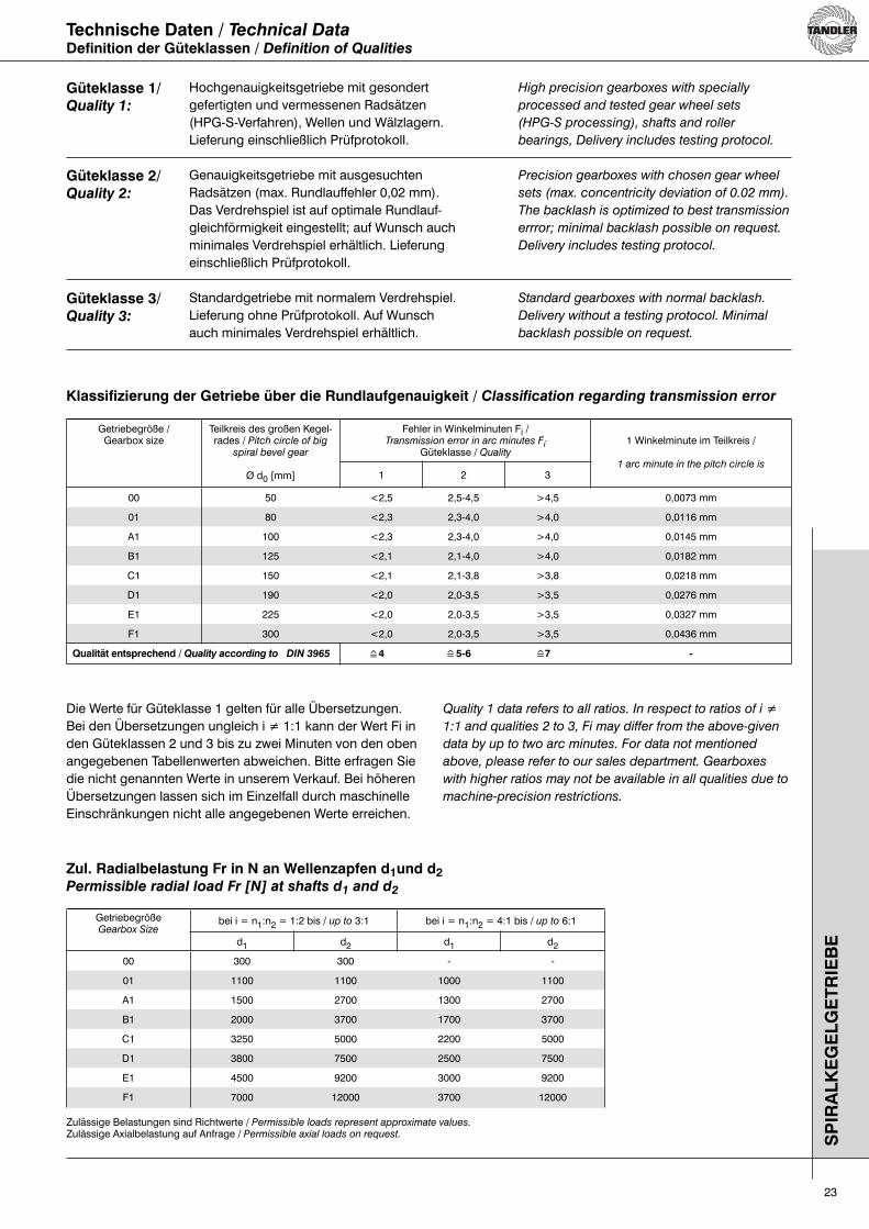
Technische Daten / Technical DataDefinition der Güteklassen / Definition of Qualities
SP
IRA
LK
EG
EL
GE
TR
IEB
E
Hochgenauigkeitsgetriebe mit gesondertgefertigten und vermessenen Radsätzen(HPG-S-Verfahren), Wellen und Wälzlagern.Lieferung einschließlich Prüfprotokoll.
Genauigkeitsgetriebe mit ausgesuchtenRadsätzen (max. Rundlauffehler 0,02 mm).Das Verdrehspiel ist auf optimale Rundlauf-gleichförmigkeit eingestellt; auf Wunsch auch minimales Verdrehspiel erhältlich. Lieferung einschließlich Prüfprotokoll.
Standardgetriebe mit normalem Verdrehspiel. Lieferung ohne Prüfprotokoll. Auf Wunschauch minimales Verdrehspiel erhältlich.
High precision gearboxes with specially
processed and tested gear wheel sets
(HPG-S processing), shafts and roller
bearings, Delivery includes testing protocol.
Precision gearboxes with chosen gear wheel
sets (max. concentricity deviation of 0.02 mm).
The backlash is optimized to best transmission
errror; minimal backlash possible on request.
Delivery includes testing protocol.
Standard gearboxes with normal backlash.
Delivery without a testing protocol. Minimal
backlash possible on request.
Klassifizierung der Getriebe über die Rundlaufgenauigkeit / Classification regarding transmission error
Getriebegröße /Gearbox size
Teilkreis des großen Kegel-rades / Pitch circle of big
spiral bevel gear
Ø d0 [mm]
Fehler in Winkelminuten Fi /Transmission error in arc minutes Fi
Güteklasse / Quality1 Winkelminute im Teilkreis /
1 arc minute in the pitch circle is1 2 3
00 50 <2,5 2,5-4,5 >4,5 0,0073 mm
01 80 <2,3 2,3-4,0 >4,0 0,0116 mm
A1 100 <2,3 2,3-4,0 >4,0 0,0145 mm
B1 125 <2,1 2,1-4,0 >4,0 0,0182 mm
C1 150 <2,1 2,1-3,8 >3,8 0,0218 mm
D1 190 <2,0 2,0-3,5 >3,5 0,0276 mm
E1 225 <2,0 2,0-3,5 >3,5 0,0327 mm
F1 300 <2,0 2,0-3,5 >3,5 0,0436 mm
Qualität entsprechend / Quality according to DIN 3965 4 5-6 7 -
Quality 1 data refers to all ratios. In respect to ratios of i ≠
1:1 and qualities 2 to 3, Fi may differ from the above-given
data by up to two arc minutes. For data not mentioned
above, please refer to our sales department. Gearboxes
with higher ratios may not be available in all qualities due to
machine-precision restrictions.
Zul. Radialbelastung Fr in N an Wellenzapfen d1und d2 Permissible radial load Fr [N] at shafts d1 and d2
GetriebegrößeGearbox Size
bei i = n1:n2 = 1:2 bis / up to 3:1 bei i = n1:n2 = 4:1 bis / up to 6:1
d1 d2 d1 d2
00 300 300 - -
01 1100 1100 1000 1100
A1 1500 2700 1300 2700
B1 2000 3700 1700 3700
C1 3250 5000 2200 5000
D1 3800 7500 2500 7500
E1 4500 9200 3000 9200
F1 7000 12000 3700 12000
Zulässige Belastungen sind Richtwerte / Permissible loads represent approximate values.Zulässige Axialbelastung auf Anfrage / Permissible axial loads on request.
Güteklasse 1/Quality 1:
Güteklasse 2/Quality 2:
Güteklasse 3/Quality 3:
Die Werte für Güteklasse 1 gelten für alle Übersetzungen. Bei den Übersetzungen ungleich i ≠ 1:1 kann der Wert Fi in den Güteklassen 2 und 3 bis zu zwei Minuten von den oben angegebenen Tabellenwerten abweichen. Bitte erfragen Sie die nicht genannten Werte in unserem Verkauf. Bei höheren Übersetzungen lassen sich im Einzelfall durch maschinelle Einschränkungen nicht alle angegebenen Werte erreichen.
=̂ =̂ =̂

24
Technische Daten / Technical DataGewichte / WeightsS
PIR
AL
KE
GE
LG
ET
RIE
BE
GetriebegrößeGearbox Size
NormalausführungStandard Version
AluausführungAluminium Version
GetriebegrößeGearbox size
GetriebegrößeGearbox size
kg kg kg kg
00 5 3 - - - -
01 11 7 S 01 12,5 W 01 15
A1 21 12 S A1 25 W A1 29,5
B1 36 23 S B1 42 W B1 50
C1 64 44 S C1 75 W C1 88
D1 124 - S D1 145 W D1 172
E1 250 - S E1 295 W E1 350
F1 455 - S F1 535 W F1 630
Die Auswahl der Schmierstoffe und deren Viskosität er-folgte unter Berücksichtigung von Bauart, Umfangsge-schwindigkeit, Zahnspiel und Betriebstemperatur derGetriebe. Die laufgeprüften Spiralkegel-Getriebe werden mit der erfor derlichen Ölfüllung, und zwar mit mineralischem CLP-ÖI nach DIN 51517 der ISO VG 46, ausgeliefert. Bei niedrigen Drehzahlen wird Getriebe-Fließfett GP 00 empfohlen und auf Kundenwunsch vorgesehen. Die Getriebe sind damit universell einsetz-bar und können überall sofort angeschlossen werden. Zur Kontrolle des Ölspiegels dient ein umsetzbares Ölauge, welches der jeweiligen Einbaulage angepasst werden kann. Da man sehr oft erst an Ort und Stelle die Einbauverhältnisse ersieht, muss im Bedarfsfall ein Monteur die entsprechende Verschluss-Schraube M 30 x 1.5 mit dem Ölschauglas austauschen bzw. umwechseln. Ölauge und Verschluss-Schraube sind mit O-Ringen abgedichtet. Je nach Betriebsbedingungen sollte die Ölfüllung nach ca. 2000 Stunden gewechselt werden. Zur Verlängerung der Ölwechselintervalle können die Getriebe auf Wunsch mit vollsynthetischem Öl ausge-liefert werden. Bei Inbetriebnahme ist sicherzustellen, dass drehende oder erwärmte Teile nicht berührt werden können.
Fettschmierung/ Grease Lubrication
0 bis 3 m/sec Umfangsgeschwindigkeit der Spiralkegelräder. 0 up to 3 m/ sec circumferential speed of
spiral bevel gear wheel.
Die Umfangsgeschwindigkeit kann mithilfe derTeilkreisdurchmesser auf Seite 23 berechnet werden.Circumferential speed may be calculated using
the pitch diameter on page 23.
Erstbefüllung/ initial fill:
Aral Aralub FDP 00 Aral Bezugsquellen/ source of supply:
www.aral-lubricants.de
The selection of lubricants and their degree of viscosity
were made taking into account the design, circumferential
speed, backlash of the teeth and operating temperature
of the gearboxes. The spiral bevel gears are delivered
after being tested and are filled with mineral CLP oil DIN
51517 from ISO VG 46. If the rotation speed is low, it is
recommended to take gearbox grease GP 00 by customer
requirement. They are universally applicable units and can
be fitted anywhere immediately. The oil level is checked by
means of a de tachable oil gauge which must be fitted to
suit the assembled position of the gearbox. Since in most
cases only an on-the-spot assessment of the assembly
arrangement is possible, your fitter, if necessary, will have
to remove one of the M 30 x 1,5 oil plugs and locate the
oil gauge in a suitable position. The oil gauge and oil
plugs are sealed with 0-rings. The oil should be changed
approximately every 2000 running hours. For longer oil
change interval the gearboxes can be delivered with fully
synthetic oil, in case of need. Installation must ensure
that no contact is possible with rotating or hot parts during
operation.
Tauchschmierung/ Splash Lubrication
Bis 15 m/ sec Umfangsgeschwindigkeit der SpiralkegelräderUp to 15 m/ sec circumferential speed of
spiral bevel gear wheel.
Über 15 m/sec wird Einspritzschmierung empfohlen.Over 15 m/sec injection lubrication is recommended.
Die Umfangsgeschwindigkeit kann mithilfe derTeilkreisdurchmesser auf Seite 23 berechnet werden.Circumferential speed may be calculated using
the pitch diameter on page 23.
Erstbefüllung/ initial fill:
Aral Degol BG 46Aral Bezugsquellen/ source of supply:
www.aral-lubricants.de
Schmierstoffe und Füllmengen/ Lubricants and Lubricant Quantities
25
Technische Daten / Technical DataFüllmengen / Lubricant Quantities
GetriebegrößeGearbox size
i = 1:1Ltr.
i 1:1Ltr.
Fett / Greasekg
00 0,10 0,10 0,20
01 0,25 0,25 0,45
A1 0,60 0,60 1,00
B1 0,75 1,10 1,60
C1 1,50 2,25 3,00
D1 3,00 4,50 6,00
E1 8,00 11,00 15,00
F1 13,00 23,00 19,00
Die Mengenangaben sind ca. Werte.Bei der Ölmenge ist das Schauglas maßgebend.
Listed quantities are approximate values.Oil-level sight glass is relevant for measuring quantity.
To ensure operational reliability the quantity of oil should not
be changed. If the oil level is too low inadequate cooling
and insufficient lubrication of the bevel pinion will occur.
If the oil level is too high, strong oil turbulence is created
with the result that churning losses and oil temperature rise
unnecessarily.
Um die Betriebssicherheit zu gewährleisten, sollte der eingefüllte Ölstand stets gehalten werden. Bei zu kleinem Ölstand tritt unzureichende Kühlung des Kegeltriebs und Mangelschmierung ein. Bei zu hohem Ölstand wird das Öl sehr stark durchgewirbelt, die Planschverluste und die Temperatur des Öles erhöhen sich dadurch unnötig.
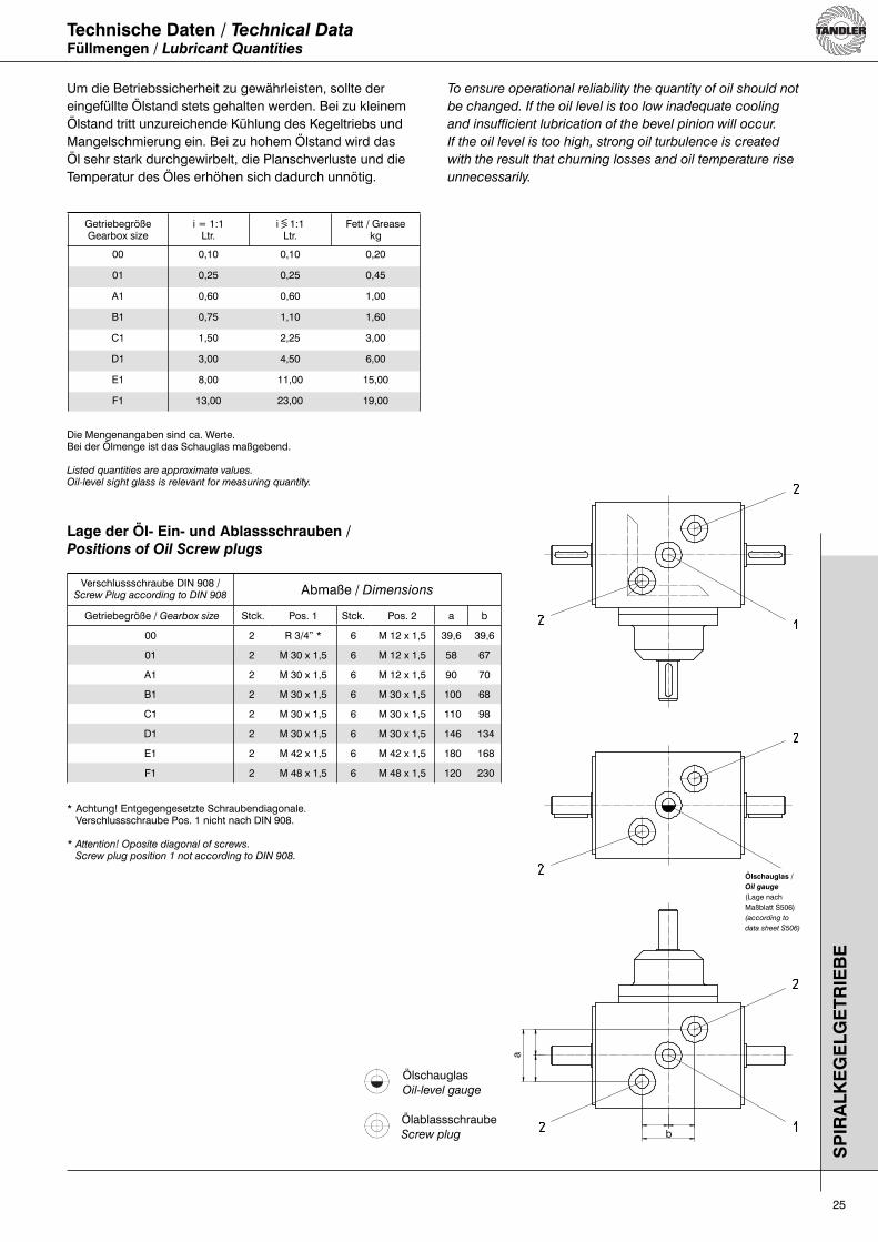
Lage der Öl- Ein- und Ablassschrauben /Positions of Oil Screw plugs
Verschlussschraube DIN 908 /Screw Plug according to DIN 908 Abmaße / Dimensions
Getriebegröße / Gearbox size Stck. Pos. 1 Stck. Pos. 2 a b
00 2 R 3/4” * 6 M 12 x 1,5 39,6 39,6
01 2 M 30 x 1,5 6 M 12 x 1,5 58 67
A1 2 M 30 x 1,5 6 M 12 x 1,5 90 70
B1 2 M 30 x 1,5 6 M 30 x 1,5 100 68
C1 2 M 30 x 1,5 6 M 30 x 1,5 110 98
D1 2 M 30 x 1,5 6 M 30 x 1,5 146 134
E1 2 M 42 x 1,5 6 M 42 x 1,5 180 168
F1 2 M 48 x 1,5 6 M 48 x 1,5 120 230
* Achtung! Entgegengesetzte Schraubendiagonale. Verschlussschraube Pos. 1 nicht nach DIN 908.
* Attention! Oposite diagonal of screws. Screw plug position 1 not according to DIN 908.
SP
IRA
LK
EG
EL
GE
TR
IEB
E
ÖlschauglasOil-level gauge
ÖlablassschraubeScrew plug
Ölschauglas /Oil gauge
(Lage nachMaßblatt S506)(according to
data sheet S506)
<>
a
b
26
Technische Daten / Technical DataAnordnung der Ölschaugläser / Arrangement of the oil-level gauges
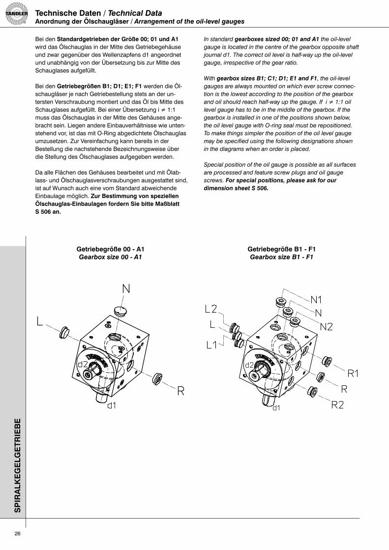
Bei den Standardgetrieben der Größe 00; 01 und A1 wird das Ölschauglas in der Mitte des Getriebegehäuse und zwar gegenüber des Wellenzapfens d1 angeordnet und unabhängig von der Übersetzung bis zur Mitte des Schauglases aufgefüllt.
Bei den Getriebegrößen B1; D1; E1; F1 werden die Öl-schaugläser je nach Getriebestellung stets an der un-tersten Verschraubung montiert und das Öl bis Mitte des Schauglases aufgefüllt. Bei einer Übersetzung i ≠ 1:1 muss das Ölschauglas in der Mitte des Gehäuses ange-bracht sein. Liegen andere Einbauverhältnisse wie unten-stehend vor, ist das mit O-Ring abgedichtete Ölschauglas umzusetzen. Zur Vereinfachung kann bereits in derBestellung die nachstehende Bezeichnungsweise über die Stellung des Ölschauglases aufgegeben werden.
Da alle Flächen des Gehäuses bearbeitet und mit Ölab-lass- und Ölschauglasverschraubungen ausgestattet sind, ist auf Wunsch auch eine vom Standard abweichende Einbaulage möglich. Zur Bestimmung von speziellen Ölschauglas-Einbaulagen fordern Sie bitte MaßblattS 506 an.
In standard gearboxes sized 00; 01 and A1 the oil-level
gauge is located in the centre of the gearbox opposite shaft
journal d1. The correct oil level is half-way up the oil-level
gauge, irrespective of the gear ratio.
With gearbox sizes B1; C1; D1; E1 and F1, the oil-level
gauges are always mounted on which ever screw connec-
tion is the lowest according to the position of the gearbox
and oil should reach half-way up the gauge. If i ≠ 1:1 oil
level gauge has to be in the middle of the gearbox. If the
gearbox is installed in one of the positions shown below,
the oil level gauge with O-ring seal must be repositioned.
To make things simpler the position of the oil level gauge
may be specified using the following designations shown
in the diagrams when an order is placed.
Special position of the oil gauge is possible as all surfaces
are processed and feature screw plugs and oil gauge
screws. For special positions, please ask for our
dimension sheet S 506.
SP
IRA
LK
EG
EL
GE
TR
IEB
E
Getriebegröße 00 - A1Gearbox size 00 - A1
Getriebegröße B1 - F1Gearbox size B1 - F1
27
Erforderliche Zusatz-Angaben bei der Bestellung:- Drehzahlen- Einbaulage (Wellen horizontal oder vertikal)- außergewöhnliche Umgebungsbedingungen
Necessary, suplementary data for your inquiry:
- speed
- Position of gears (shafts horizontal or vertical)
- Special service environment
Bestellbeispiel / Order Example
Baureihe / Series
Getriebegröße / Gearbox Size
Gesamtübersetzung / Overall Ratio i = n1:n2
Räderanordnung / Gear wheel arrangement
Sonderausführung / Special Design
HW - A1 - 2:1 - III - S...
Produktmerkmale / Product Characteristics
• Hochleistungsgetriebe mit geräuscharmem Lauf
• Hohe Genauigkeit und Rundlaufgleichförmigkeit
• Kleinst mögliche Verdrehspiele
• Spiralkegelräder aus legiertem Einsatzstahl, gehärtet und auf bestes Tragbild geläppt
• Alle Radsätze können in Palloid-, Zyklo-Palloid oder HPG-S gefertigt werden
• Hochgenauigkeitswälzlager nach TANDLER-Werks-Norm SQ47 (P5)
• High Performance Gearboxes - Quiet Operation
• High Precision and Concentricity
• Minimal Backlash
• Spiral bevel gears from Alloy Carburited Steel, Hardened and Lapped to give Best Surface Contact
• All gear sets may be processed with Palloid, Cyclo Palloid and HPG-S cutting
• High Precision Bearings to TANDLER Works Standard SQ47 (P5) SP
IRA
LK
EG
EL
GE
TR
IEB
E
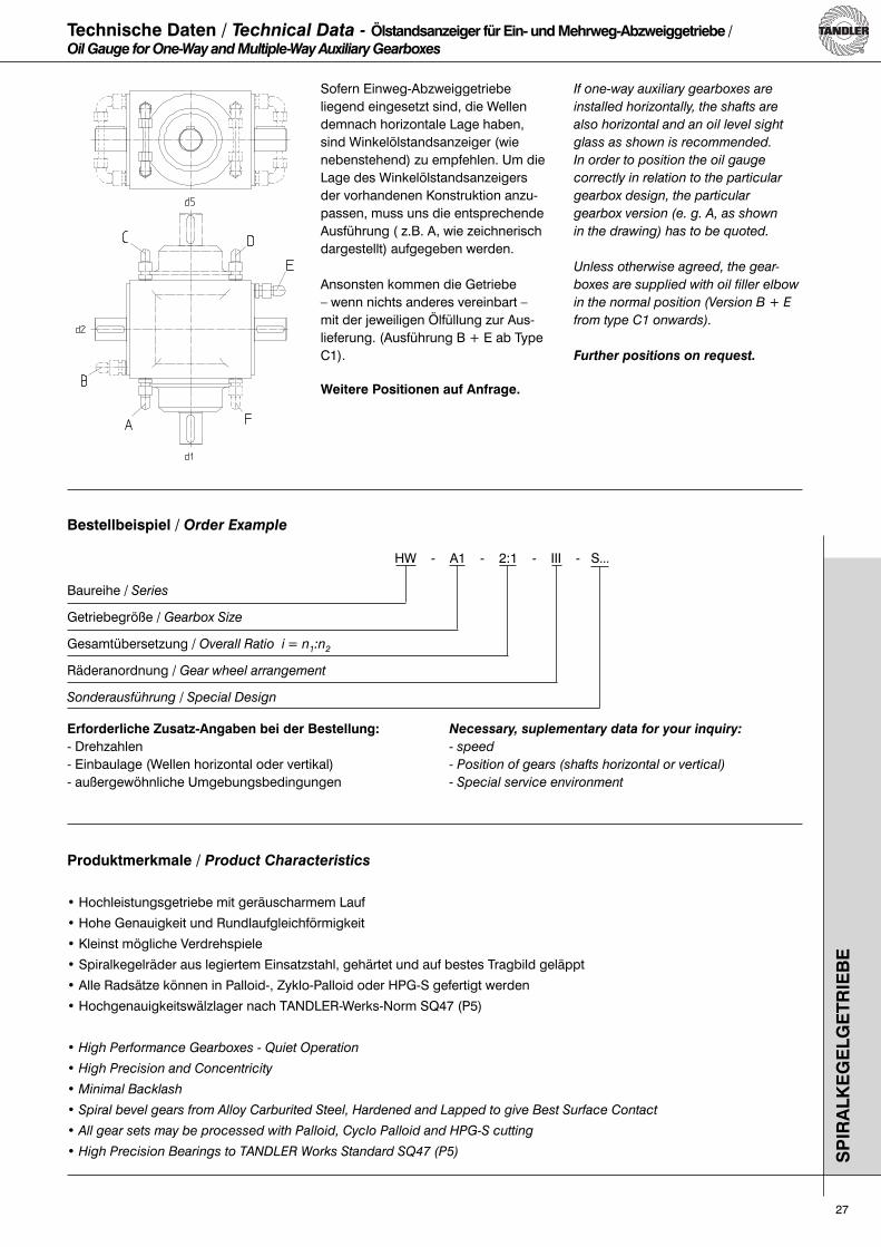
Sofern Einweg-Abzweiggetriebe liegend eingesetzt sind, die Wellen demnach horizontale Lage haben, sind Winkelölstandsanzeiger (wie nebenstehend) zu empfehlen. Um die Lage des Winkelölstandsanzeigers der vorhandenen Konstruktion anzu-passen, muss uns die entsprechende Ausführung ( z.B. A, wie zeichnerisch dargestellt) aufgegeben werden.
Ansonsten kommen die Getriebe – wenn nichts anderes vereinbart –mit der jeweiligen Ölfüllung zur Aus-lieferung. (Ausführung B + E ab Type C1).
Weitere Positionen auf Anfrage.
If one-way auxiliary gearboxes are
installed horizontally, the shafts are
also horizontal and an oil level sight
glass as shown is recommended.
In order to position the oil gauge
correctly in relation to the particular
gearbox design, the particular
gearbox version (e. g. A, as shown
in the drawing) has to be quoted.
Unless otherwise agreed, the gear-
boxes are supplied with oil filler elbow
in the normal position (Version B + E
from type C1 onwards).
Further positions on request.
Technische Daten / Technical Data - Ölstandsanzeiger für Ein- und Mehrweg-Abzweiggetriebe /Oil Gauge for One-Way and Multiple-Way Auxiliary Gearboxes

TANDLER Zahnrad- und Getriebefabrik GmbH & Co. KG
Kornstraße 297-301D-28201 BremenDeutschland / Germany
Tel.: +49 (0) 421 - 53 63 6Fax: +49 (0) 421 - 53 63 801
Technische Änderungen vorbehalten. / Technical data is subject to changes.
SpiralkegelgetriebeSpiral Bevel Gearboxes
Ges
taltu
ng
: w
ww
.bo
rrek
-desig
n.d
e
03.07