split-charge manual a4
TRANSCRIPT


Contents! What�s in the kit?
! About Split-Charge systems
! Glossary of terms
! Before Installation
! Safety considerations
! Wiring diagram
! Basic Installation
! Fitting the Dual Battery Controller
! Basic sytem operation - How it works
! Operating the Dual Battery Controller
! Typical monitor readings
! Battery basics - A simple guide
! Extended Split-Charge configurations
! Technical system operation
! Cable / Wiring losses
What’s in the kit ?
2
2
3
3
4
4
5
5
6
6
7
8
9
10
11
You should have the following parts included in this kit :
1 x Intelligent solenoid (Isolator unit)
1 x Dual battery controller (Monitor)
1 x 3.5 metre data cable26 metres RED 16mm power cable
26 metres BLACK 16mm power cable
Note - Not all components are required for a full installation. Accomodation has been made for variances in battery types and vehicle makes.
Positive battery terminals
Negative battery terminals
2 x In-line power fuses
1 x 15 Amp accessory fuse
Assorted terminations and fasteners
Assorted cable ties.
Although the supplied cable is double-insulated, protective cable sleeving is recommended for all installations (not supplied in this kit).
12

FUSE BLOWN
SOLENOID ENGAGED
TIMER ACTIVE > 13.1 Volt
INTELLIGENTSOLENOID
SPLIT CHARGING SYSTEM
SPIKE
PROTECTED
SPIKE
PROTECTED
Split Charging Systems1. Manual battery change-over switch - this requires the driver of the vehicle to switch from the main battery to the auxiliary battery or vice versa. However, the NEGATIVE of this system is that you disconnect a battery from the alternator and it may never get a full charge (Causing permanent damage to the battery).
2. Relay type systems - these typically use a small automotive relay which is not capable of handling the continuous current required to charge the auxiliary battery. These systems also tend to work off the ignition which connects both batteries immediately when the car is started. Wiring done by auto electricians is too often too thin to handle the power required in a good split-charging system.
3. Time delay systems - these are now recognized by most 4x4 specialists as a better methodology whereby the main battery gets a full charge for approximately 5 minutes before connecting both batteries in parallel. The time delay function has been introduced to protect the vehicle’s alternator, as well as enabling the main battery to recover lost charge before introducing the auxiliary battery Normally these are activated by the ignition. (ie. The sensing wire has to be connected into the vehicle’s electrical system).
• WIRING LOSS - This refers to voltage loss in an electrical conductor (e.g. from the alternator to the battery, when a thin wire is connected). The voltage loss is of such magnitude so as to create an artificially low voltage to the battery under charge. This causes a slower charge rate to the battery. In some cases a battery may take up to three times longer to charge as a result of thin wiring.
• VOLTS (V) - In the off-road market, the available power source is normally a 12 volt DC (direct current) main car battery and an additional auxiliary battery. (A car battery consists of six 2-Volt cells to get a nominal 12volt DC battery)
• AMPS (A) - Current flow is measured in amps that is being consumed by the electrical device to make it work.
• WATTS (W) - This is total power calculated by multiplying volts x amps. Mathematically a drop in volts (V) will increase the current draw amps (A) in order to provide the necessary power in watts (W) to drive the electrical device.
• AMBIENT TEMPERATURE - This is the prevailing temperature of the air surrounding the battery.• HIGH CYCLE BATTERY - High cold cranking Amp "CCA" - normally accepts fast charging and should not be fully discharged• DEEP CYCLE BATTERY - Typically can be discharged completely - but takes a long time for recharging.• LED - LIGHT EMITTING DIODE - Electronic component used to indicate and "light up".
Glossary of Terms
3
DO NOT RELY ON THE VEHICLE’S BODY TO PROVIDE A NEGATIVE ELECTRICAL EARTH PATH
Normal Motor Vehicle Charging System
Alternator
NATIONAL LUNA has in it's experience of field problems, and discussions with leading world-wide 4x4 specialists, developed a fully comprehensive split charging system, which caters for all conditions of battery charging.
This system has been specifically designed not to interfere with the motor vehicle’s electrical system.
THERE ARE A NUMBER OF SPLIT CHARGING SYSTEMS BEING OFFERED TO THE 4X4 INDUSTRY.
FUSE BLOWN
SOLENOID ENGAGED
TIMER ACTIVE > 13.1 Volt
INTELLIGENTSOLENOID
SPLIT CHARGING SYSTEM
SPIKE
PROTECTED
SPIKE
PROTECTED

Before commencing with the installation, the NEGATIVE TERMINAL of the main vehicle battery should be Only re-connect the negative terminal after the rest of the installation is complete and checked.
Battery cables between the two batteries must be securely tied down to the vehicle to prevent cháfing. Care must be taken that the battery cables are kept well clear of any moving parts or excessively hot areas of the vehicle
2that may damage them. The 16mm power cable supplied with the kit has a double insulation for extra protection.
Do not secure the cables underneath the vehicle in such a way that they may be vulnerable under severe off-road conditions. If a cable is to be tied down to the chassis, ensure that there is enough play on the cable to withstand full suspension movement. (It is often best to follow existing brake-lines and wiring along the chassis).
(preferably mounted in a suitable battery bracket).
disconnected asa safety precaution.
All batteries must be secured to the vehicle
Safety Considerations
Before InstallationBefore installation of your split-charge system, make sure that your vehicle’s electrical system is compatible:
Installing a secondary battery in your vehicle increases the work load on your vehicle’s alternator. It is important to check that your alternator can maintain sufficient voltage to charge the batteries with the additional load.
Testing your alternator.
With the engine running, measure the voltage across the terminals of your main battery using a voltmeter. Turn on the vehicle lights, air-conditioner and any other load (such as spot-lights). Measure the voltage on the battery again. If the voltage has dropped below 13.5 volts then it is recommended that the alternator performance be checked.
The voltage should be above13.5 volts.
The alternator regulator or power output may have to be upgraded by an auto-electrical technician.A regulated voltage above 14.0 volts under load is preferable for optimal auxiliary battery charging.
It is recommended to install fuses (labeled “FUSE 1” & “FUSE 2”) in the main current path. These fuses should be rated at the maximum expected current during normal operation (between 50A and 100A).
If an unexpected overload occurs, these fuses will isolate both batteries from the source of the fault. The appropriate fuse(FUSE 3) rating, depending on the load from the auxiliary battery, should be selected.
4
WARNING !The Split-Charge Kit has been designed not to interfere with the motor-vehicle’s electrical system.
There is a tendency to use the vehicle’s chassis as an electrical earth path. It is convenient to adopt this attitude as it is sometimes awkward to route a heavy-duty cable over the length of a vehicle.
Use the supplied BLACK cable to connect the MAIN and AUXILIARY negative terminals.
In the event of a poor earth connection, the current flow will find a path through the motor vehicle’s standard wiring. This wiring is not suitable for typical battery charging currents
and may result in BURNING or PERMANENT DAMAGE to other electrical equipment.
Double-check all connections and crimping!Poor connections will affect the performance of the system!
On some vehicles, removing any terminal of the main battery may affect alarms and/or engine management systems
In this case, the installation can be performed “live” - EXTREME CAUTION is advised when connecting and handling wiring.
(Refer to your vehicle’s handbook relating to battery connections).

AUX BA
RTTE
YMA
NI
R
ATTEY
B
WIRING DIAGRAM2
(16mm power cable)
FUSE 250A
Accessory / Auxiliary output
FUSE BLOWN
SOLENOID ENGAGED
TIMER ACTIVE > 13.1 Volt
INTELLIGENTSOLENOID
SPLIT CHARGING SYSTEM
SPIKE
PROTECTED
SPIKE
PROTECTED
4
1
3
2
FUSE 1100A FUSE 3
15A
5
Basic Installation
Install the 100A fuse (fuse 1) provided as close to the main battery as possible. Using the cable and lugs supplied, make a connection between the positive terminal of the main battery to one of the terminals of the fuse holder.
Connect the free terminal of the fuse holder to the terminal marked “MAIN BATTERY” on the Intelligent Solenoid unit using a short piece of cable and the lugs supplied.
Connect the remaining cable to the terminal marked “AUXILIARY BATTERY” using the lugs supplied. Connect the in-line fuse (fuse 2 - 50A) and then to the positive terminal of the auxiliary battery.
Connect the BLACK cable from the negative terminal of the main battery to the negative terminal of the auxiliary battery.
RED
RED
RED
FUSE BLOWN
SOLENOID ENGAGED
TIMER ACTIVE > 13.1 Volt
INTELLIGENTSOLENOID
SPLIT CHARGING SYSTEM
SPIKE
PROTECTED
SPIKE
PROTECTED
UPThe electronics of the Intelligent Solenoid are not encapsulated in resin to form a completely waterproof product. It is important to mount the Solenoid in an upright position to prevent moisture build-up caused by washing the engine.
There are cases where it is not practical to mount the unit upright. The unit can be mounted in a horizontal position (provided it is installed away from all sources of water contamination).
STEP 1
STEP 2
STEP 3
1
2
4
3
STEP 4 (NB - THIS MUST BE THE LAST CONNECTION MADE)
TIMER ACTIVE > 13.1 Volt
Dual Battery Controller port
Mounting the Intelligent Solenoid
( DO NOT USE THE VEHICLE CHASSIS AS AN ELECTRICAL EARTH PATH!! )
Connect the BLACK earth wire from the Intelligent Solenoid to the negative terminal of the main battery. The circuit will now be powered and will result in the (ie. ) on the unit flashing once.
If the GREEN light does not flash once only, remove the connection and reconnect. (RESET)
GREEN LIGHT
FUSE BLOWN
SOLENOID ENGAGED
TIMER ACTIVE > 13.1 Volt
INTELLIGENTSOLENOID
SPLIT CHARGING SYSTEM
SPIKE
PROTECTED
SPIKE
PROTECTED

How it Works !
6
Once the Intelligent Solenoid is installed, the Dual Battery Controller/Monitor can be connected.Route the 3.5m monitor cable (supplied) from the Intelligent Solenoid Unit to the location where the Dual Controller will be mounted.
Fitting the Dual Battery ControllerFUSE BLOWN
SOLENOID ENGAGED
TIMER ACTIVE > 13.1 Volt
INTELLIGENTSOLENOID
SPLIT CHARGING SYSTEM
SPIKE
PROTECTED
SPIKE
PROTECTED
Start the vehicle: The LED on the Intelligent Solenoid unit will start to flash.
After switching off the vehicle: The Intelligent Solenoid will monitor battery voltage. Depending on the type and capacity of the batteries installed, ambient temperature, and loads connected to the system, the rate at which the battery voltage drops will vary.
After the timer has elapsed, the solenoid will connect and the LED will come on. At this point, charge will then be allowed to flow to the auxiliary battery.
The Intelligent Solenoid will disconnect once battery voltage has dropped below 12.65 volts.
Plug one end of the cable into the port on the Intelligent solenoid unit. Make sure the cable clips into place and doesn’t pull loose.
At this point, power will be applied to the Dual Battery Controller and the displays will show the voltage levels of both main and auxiliary batteries.
The remaining plug connects to the Dual Battery Controller. The plug must be inserted at an angle in order to allow the locating pins to enter the Controller housing and be clipped in place.
1
2
The Intelligent Solenoid works by sensing the increased charge voltage on the main battery. (This allows the unit to detect when the battery is being charged.)
The Intelligent Solenoid will not allow a connection if the auxiliary battery ........has reverse polarity, is short-circuited, or does not exist.
The Intelligent Solenoid
Make sure the plug mates firmly with the matching connector on the Dual Battery Controller and doesn’t pull loose.
(If one of these batteries is not present, the appropriate display will flash and an alarm will be heard).
TIMER ACTIVE > 13.1 Volt
TIMER ACTIVE > 13.1 Volt
SOLENOID ENGAGED
SET ON
FUSE BLOWN
SOLENOID ENGAGED
TIMER ACTIVE > 13.1 Volt
INTELLIGENTSOLENOID
SPLIT CHARGING SYSTEM
SPIKE
PROTECTED
SPIKE
PROTECTED
FUSE BLOWN
Once the LED has started to flash, an internal timer starts. (Expect the LED to flash for 5 minutes).
The LED will indicate that there is an fault which has caused the internal fuse to blow.This can happen if the Solenoid contacts are accidentally short-circuited, or there is water damage to the electrical circuit.
In order to replace the internal fuse, the Intelligent solenoid will need to be removed and the housing screws removed.The fuse must be replaced with the same type and rating for correct operation.It is recommended that a service agent carry out this repair and check for any further damage.

7
The Controller is fitted with two displays (one each for main and auxiliary batteries). If either of these batteries are not installed, the Controller will warn the user of this situation with an audible alarm (if enabled) and a flashing warning on the appropriate display. The alarm will stop once battery voltage has risen above 12.0V.
A special feature of the is its ability to “over-ride” the and allow the user to force the main and auxiliary batteries to connect. This is particularly useful when a winch is used or for “jump-starting” from the auxiliary battery.
Dual Battery Controller Intelligent Solenoid
If the Timer over-ride feature is used for jump-starting, it is likely that the in-line fuses will blow. To prevent this from happening,activate the over-ride facility and allow a few minutes for charge to flow from the auxiliary battery to the main battery before attempting to start the engine. Alternatively, increase the ratings of in-line fuses (Fuse 1 & Fuse 2)
Activating / De-activating the display
Activating / De-activating the alarm
Note that a beep will occur after 3 seconds (ALARM SET), but that the button must be held for an additional 2 seconds until the display changes. (The alarm is not activated/de-activated in this sequence)
The Timer Over-Ride allows the user to send a signal to the Intelligent Solenoid, instructingthe system to connect.
To enable the timer-overide facility, press and hold the “ON” button for 3 seconds or until a short beep is heard.
When active, the “TIMER OVER-RIDE” light will flash and will remain active for 5 minutes only. Use the same procedure to de-activate the timer “over-ride”.
The user has the option to turn both displays off. If this option is selected, the Controller will still function normally and will“wake-up” if any error conditions occur.Both displays on the Dual Battery Controller are on by default. To turn the display off, press and hold the ‘SET’button until the display disappears (approx. 5 seconds). To re-enable the display, the same procedure is used.
The alarm on the Dual Controller is on by default. To de-activate the alarm, press and hold the ‘SET’ button for 3 seconds or until a short beep is heard and the ALARM light goes out. To activate the alarm, the same procedure is used.
Over-voltage / Excessive discharge (See ILLUSTRATION C)
If an over-charge condition exists (ie. above 14.65V) on either battery, the Controller will flash the top 4 green lights on the relevant display and an audible alarm will be heard (if enabled).
Similarly, if the voltage on either battery drops below 11.4V, the Controller will flash the bottom red light on the appropriate display and an audible alarm will be heard (if enabled). The same low-voltage warning will be shown if either battery is missing. (eg auxiliary battery not connected - typical with a removable battery or trailer / caravan connection). (The low-voltage alarm will stop once voltage has risen above 12.0V.)
Timer Over-ride
Factory Default settings
When the Dual Battery Controller is plugged in, the audible alarm and display will be operational by default.If these settings are changed and the Controller is subsequently unplugged, the Dual Controller will revert to the default setting once plugged in again. (Ie. Settings are not saved)
SET
ON
SET
SET ON
SET ON
MAIN battery display.
AUXILIARY battery display.
ALARM status LED
TIMER OVER-RIDE status LED
ALARM/DISPLAY BUTTON
TIMER OVER-RIDE BUTTON
21
43
1
2
3
4
5
65 6
Dual Battery Controller Operation
Some vehicle alternators have a “boost mode” function. This often occurs after starting (or when cold) where a higher charging voltage (up to 15V) may be applied to the battery for a period of time (about 10-15 minutes).
In such cases, the overvoltage alarm will activate during this period.

100% 75% 25%50% 10%
11.0
10.5
11.5
12.5
12.0
13.0
13.5
14.0
BA
TT
ER
Y V
OLT
AG
E (
V)
% BATTERY CAPACITY
FL
OA
TIN
G C
HA
RG
E
SET ONSET ON
8
Typical Monitor Readings @ 25°C
SET ON
Illustration A Illustration B
Illustration C Illustration D
Illustration E Illustration F
READING THE BATTERY MONITOR BEFORE STARTING (i.e. in the morning).The monitor will reflect the battery readings with three RED LED's and between five and six of the ORANGE LED’s lit up. This will indicate that the both batteries are in good condition and that the voltages are 12.5 volts or above.
The DUAL BATTERY MONITOR has been developed to provide the user with information on both the main car battery and the auxiliary battery. The unit will provide an LED display indicating the voltage reading on the battery and give an approximate idea of the state of charge of the battery. The most accurate reading will be obtained at 25°C.
Illustration A
Assuming that a fridge (auxiliary load) has been connected to the auxiliary battery and is still running, the reading on the auxiliary battery could read three RED LED's. This would indicate that the battery is between11.8 volts and 12.0 volts, but that one is operating in the last 25% of battery capacity. This is near the area of , and it is important to re-charge the battery as soon as possible.
EXCESSIVE DISCHARGE
Illustration B
Over-voltage alarm (Main Battery)If the Main battery voltage rises above 14.65V, the Dual Controller will alert the user of this condition by flashing the top 4 LED’s and an audible alarm will be heard (if enabled).
Low-voltage alarm : (Auxiliary battery)Should the voltage drop below 11.4 volts, the audible alarm will activate and the red alarm LED will flash. (The alarm can be switched off, since it may not always be practical to recharge the battery immediately.)
Illustration C
Illustration D Main battery low:Should the main battery voltage be significantly lower than the auxiliary battery voltage, it is possible that the battery may be damaged or it hasbeen drained by a load (ie. Alarm system, radio, lights, etc).
Illustration E Car started: (Before Intelligent Solenoid connection)The alternator will supply voltage to the main battery once the engine isstarted. At least 3 GREEN LED’s (>13.7V) should be expected. If only 1 or 2GREEN LED’s are shown, inspect your charging system for faults.One can test the alternator regulation by switching on headlamps, air-conditioner, or any other loads. A significant drop in reading indicates a faulty alternator.
Illustration F Car running: (After Intelligent Solenoid connection)Once the solenoid connects, the auxiliary battery will now receive a charge from the alternator. Both displays should reflect similar readings.It is possible that only 2 GREEN LED’s will be displayed initially. This occurswhen the auxiliary battery is flat and is accepting maximum charge.Over time, expect 3 to 4 green LED’s to be shown as the battery charges.
SET ON
SET ON SET ON
Voltages measured above 12.6V on the battery indicate that the battery is fully charged and may have a
The Dual Battery Controller follows this curve and gives a good estimate of battery capacity based on voltage.
It can be seen that the battery voltage collapses below 11.8V. At this point the battery is considered to be flat.
Note - Damaged or aged batteries may show a “fully charged” voltage, but the battery capacity could still be less than 50%!!. Typically, a rapid drop of the Dual Controller display will indicate this problem.
“floating charge”
11.8
11.4
12.1
12.5
12.3
13.0
13.2
14.2
11.6
12.0
12.4
12.2
12.6
13.7
25%
10%
45%
80%
60%
18%
35%
75%
50%
100%
FL
OA
TIN
GC
HA
RG
E
10.5 0%
Typical voltage-capacity relationship of a lead-acid battery at 25°C.

Battery Basics
The following battery information serves as a simple guide only.
9
Batteries are typically described in two ways: By application (what they are used for) and construction (how they are built).
Application examples are: Automotive, marine, solar electrical (PV), standby power, leisure (RV), etc.
Construction relates to the physical and chemical characteristics. ie. flooded, gelled, and AGM (Absorbed Glass Mat). Flooded may be standard (with removable caps - typical car battery), or the so-called "maintenance free" type.
Generally, battery life-span is related to time, temperature, number of charge/discharge cycles and most importantly, thedepth of discharge and subsequent recharge rate.
It is preferable to fit a large capacity auxiliary battery. Fitting a small battery increases the number of charge/discharge cycles for a specific application and deep discharges are more likely to occur (reducing the battery life considerably).When choosing a battery for your specific application, one should consider the following : How deep do you expect to discharge the battery?What capacity do you require? A higher capacity battery (Ampere hours) allows longer usage before the need to re-charge.
High cycle batteries (starting batteries) are commonly used to start and run engines. Engine starters need a very large starting current for a very short time. The high cycle batteries have a large number of thin plates, ensuring large surface area, this allows the high cycle battery to supply a large current for short periods and re-charge quickly.If high-cycle batteries are deep-discharged, the plates will deteriorate quickly and reduce battery life considerably.
Deep cycle batteries have thicker plates and can be discharged by as much as 80%. These type of batteries generally take much longer to re-charge than high-cycle batteries.
The National Luna battery monitor has been designed to accurately indicate the charge state of the battery and give the user the choice of using either High-cycle or Deep-cycle batteries.
This Split-Charging kit has been designed to be compatible with standard motor vehicle charging systems.
Obviously, in the world-wide market, a huge variety of batteries and technical designs exist. Exact battery characteristics may differ between battery technology, manufacturer, age and temperature.The user must select an available auxiliary battery best suited for his purpose.
More detailed battery information can be obtained from the following sources : www.batteryuniversity.com www.windsun.com www.batterycouncil.org
! For all lead-acid technologies, batteries should be fully re-charged as soon as possible after any usage.! Batteries should never be left in a “flat” state even if they are disconnected.! Re-charge the battery with the battery manufacturers recommended charge voltage. There are a number of different alternator charging voltage standards in the motor industry. These can be categorised to : 13.7V, 14.2V and 14.5V. The user should ensure that the correct battery is selected to match this charging voltage. In many cases the alternator can be adjusted / upgraded for an optimum charge voltage.
Major battery types :
Choosing a battery for your application :
High cycle vs Deep cycle :
Obtaining maximum battery life

UAX
BT
RAT
EY
XAU
RY
BATE
T
U
AX
TY
AER
BT
AMIN
BT
ATERY
10
Extended Configurations
FUSE BLOWN
SOLENOID ENGAGED
TIMER ACTIVE > 13.1 Volt
INTELLIGENTSOLENOID
SPLIT CHARGING SYSTEM
SPIKE
PROTECTED
SPIKE
PROTECTED
FUSE 2
2 2 Configuration 1 - 2 x Auxiliary batteries in parallel (16mm -25mm power cable)
FUSE 1100A
Sometimes extra capacity is required for large equipment or for extended periods between re-charging.Simply connect a second auxiliary battery in parallel with the first. The total capacity of the battery bank will now be the sum of the individual battery capacities.It is recommended to use the same size and manufacturer of thebatteries in the auxiliary bank.
Note that if FUSE 2 is used, it must be of a sufficient rating to accomodate charge current to both auxiliary batteries.
These extended configurations show additional options for installing your split-charge system.
Make sure your vehicle alternator is capable of delivering the necessary power to sustain the increase in load.For best results, use the recommended cable thickness and proper cable terminations.
2 2 Configuration 2- Extra auxiliary battery in a caravan or trailer. (25mm - 35mm cable)
2Configuration 3 - Split charge system with a winch fitted (35mm cable required)
FUSE BLOWN
SOLENOID ENGAGED
TIMER ACTIVE > 13.1 Volt
INTELLIGENTSOLENOID
SPLIT CHARGING SYSTEM
SPIKE
PROTECTED
SPIKE
PROTECTED
If a dual-battery system is fitted to a vehicle with a winch, 2it is recommended to use 35mm cable.
Ensure that proper connections are made when fitting a winch because of the high current used while winching.
It is also recommended to fit a large MAIN vehicle battery with a high “Cold Cranking Amps” (CCA) rating which can deliver high current for short durations.
FUSE BLOWN
SOLENOID ENGAGED
TIMER ACTIVE > 13.1 Volt
INTELLIGENTSOLENOID
SPLIT CHARGING SYSTEM
SPIKE
PROTECTED
SPIKE
PROTECTED
FUSE 2100A
FUSE 350A to 100ADC Couplers
FUSE 1100A
Sometimes caravans and 4x4 trailers are equipped with batteries. In order to charge these batteries, it is necessary to connect the themto the vehicle’s charging system. To do this, use a heavy duty coupler
2 2and 25mm to 35mm cable (in order to minimise voltage losses).
It is recommended to fit another in-line fuse close to the 2nd auxiliarybattery (Fuse 3) for safety.
AN
MI
B
TE
YT
R
A
AN
MI
B
TE
Y
AT
RX
AU RY
BATE
T
XU
AB
TRY
AE
T
A number of people install winch cables to the auxiliary battery. This is not recommended as the alternator supplies a large portion of current to the winch, ensuringoptimum winch speed and power.
Note that fuses are not appropriatefor this configuration because of thehigh current flow expected.
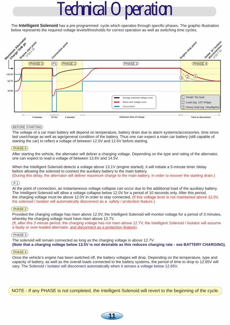
The voltage of a car main battery will depend on temperature, battery drain due to alarm systems/accessories, time sincelast use/charge as well as age/general condition of the battery. Thus one can expect a main car battery (still capable of starting the car) to reflect a voltage of between 12.0V and 12.6V before starting.
After starting the vehicle, the alternator will deliver a charging voltage. Depending on the type and rating of the alternator, one can expect to read a voltage of between 13.6V and 14.5V.
When the Intelligent Solenoid detects a voltage above 13.1V (engine started), it will initiate a 5-minute timer /delay before allowing the solenoid to connect the auxiliary battery to the main battery.
At the point of connection, an instantaneous voltage collapse can occur due to the additional load of the auxiliary battery.The Intelligent Solenoid will allow a voltage collapse below 12.0V for a period of 10 seconds only. After this period, the charging voltage must be above 12.0V in order to stay connected.
Provided the charging voltage has risen above 12.0V, the Intelligent Solenoid will monitor voltage for a period of 3 minutes, whereby the charging voltage must have risen above 12.7V.
The solenoid will remain connected as long as the charging voltage is above 12.7V.
Once the vehicle’s engine has been switched off, the battery voltages will drop. Depending on the temperature, type and capacity of battery, as well as the overall loads connected to the battery systems, the period of time to drop to 12.65V will vary.
(During this delay, the alternator will deliver maximum charge to the main battery, in order to recover the starting drain.)
(If this voltage level is not maintained above 12.0V, the solenoid / Isolator will automatically disconnect as a safety / protection feature.)
(If, after this 3 minute period, the charging voltage has not risen above 12.7V, the Intelligent Solenoid / Isolator will assumea faulty or over-loaded alternator, and disconnect as a protection feature).
(Note that a charging voltage below 13.5V is not desirable as this reduces charging rate - see BATTERY CHARGING).
The Solenoid / Isolator will disconnect automatically when it senses a voltage below 12.65V.
Technical Operation
PHASE 0
BEFORE STARTING
P 1
PHASE 2
PHASE 3
PHASE 4
The Intelligent Solenoid has a pre-programmed cycle which operates through specific phases. The graphic illustration below represents the required voltage levels/thresholds for correct operation as well as switching time cycles.
11
NOTE - If any PHASE is not completed, the Intelligent Solenoid will revert to the beginning of the cycle.
12.0V
12.7V
>13.1V
5 minutes 3 minutes10 sec
ns
i
Enge
tart
pnt
i
o
1
(>13
. V
)
C
nc
no
t
one
tio p
in
e s
p oin
t
Engin
top
PHASE 0 PHASE 2 PHASE 3 PHASE 4
123
l
Max
imu
Ate
rnat
o
m
r
C
rge
ola
ha
Vt
ge
P1
Son
o
r
leo
id/ I
lto
sa
so
n
n
dic
ne
tiocV)
(<12
.7
Worst-case voltage curve
Cut-out level
Average expected voltage curve 1
2
3
Small / No load
Load (eg. 12V fridge)
Heavy load (eg. Headlights)
Unknown time of charge Time to disconnect

TechnicalEnquiries
www.nationalluna.com
National Luna - South Africa
Tel : +27(0) 11 452-5438Fax : +27(0) 11 452-5263
e-mail : [email protected]
Cable LossesFor a typical installation, there will be voltage losses experienced with any cable used.The term “Cable losses” refers to the voltage that is “lost” over the length of the cable due to the resistance of the conductors.As voltage losses are only apparent when there is current flow, one cannot test for these losses without a load attached to the system.
To minimise voltage loss, check for the following :
2Has the correct cable been used for the installation ? (minimum of 16mm is recommended)Are the cables terminated with good connections ? (poor connections increase losses)Has the cable been kept as short as possible ? (cable resistance is proportional to its length)
Below is a table comparing cable cross sectional area (thickness) to expected voltage lost per meter of cable length.(Note that specifications may differ between different manufacturers of cables).
Keep in mind that these losses reflect the cable losses only, there will be more losses experienced wherever there are fuses, connections and terminals and that voltage loss changes with a change in current flow.
From the above information, it may seem that the losses are not significant. It is however essential to realise that a small change in voltage applied to a battery may change the charging rate dramatically.
Cable losses at DC current of 10, 20 and 40 Amps (experienced as volts per meter)
Cable cross section Voltage loss @ 10 Amps
24mm
26mm
210mm
216mm
225mm
235mm
Voltage loss @ 20 Amps Voltage loss @ 40 Amps
0.10 V/m
0.06 V/m
0.04 V/m
0.02 V/m
0.02 V/m
0.01 V/m
0.19 V/m
0.13 V/m
0.08 V/m
0.05 V/m
0.03 V/m
0.02 V/m
0.38 V/m
0.26 V/m
0.15 V/m
0.10 V/m
0.06 V/m
0.04 V/m
For the total cable loss, multiply the voltage loss per meter by the number of meters used.
It is also important to realise that the total length of your cable includes the return path.This means the total length of cable from the battery (source) to the load and back again to the battery.(i.e. If all the cable used in this kit is used, the total cable length is12 meters).
Example - An installation requires 6 meters of RED cable and 6 meters of BLACK cable. The total cable length is 2 2 12 meters. Compare the voltage losses of 4mm cable and 16mm cable when a current of 20A flows.
24mm cable - 0.19 Volts / meter x 12 meters = 2.28 volts lost.
216mm cable - 0.05 Volts / meter x 12 meters = 0.6 volts lost.
A battery connected to a 14.2 volt alternator will now only receive 11.9volts. This voltage is insufficient to charge the battery at any significantcurrent. The battery will not be fully charged.
A battery connected to a 14.2 volt alternator will now receive 13.6 voltsThis voltage is not ideal, but will allow the battery to be charged at a highrate. As the battery charges, current is reduced and less voltage is lost.