split room ac installation
TRANSCRIPT
8/2/2019 Split Room AC Installation
http://slidepdf.com/reader/full/split-room-ac-installation 1/15
8/2/2019 Split Room AC Installation
http://slidepdf.com/reader/full/split-room-ac-installation 2/15
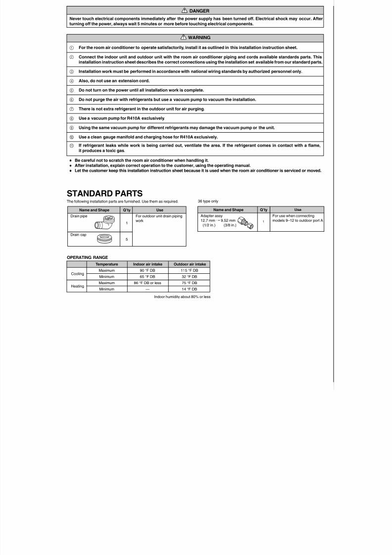
DANGER
Never touch electrical components immediately after the power supply has been turned off. Electrical shock may occur. After
turning off the power, always wait 5 minutes or more before touching electrical components.
WARNING
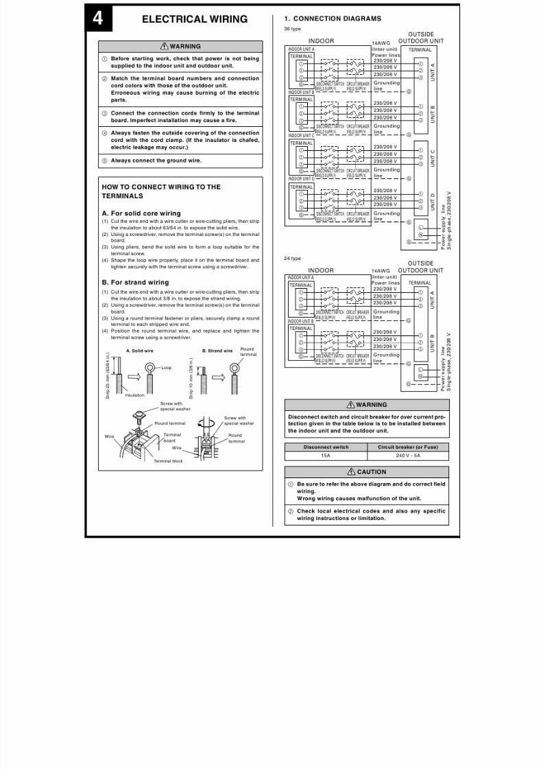
1 For the room air conditioner to operate satisfactorily, install it as outlined in this installation instruction sheet.
2 Connect the indoor unit and outdoor unit with the room air conditioner piping and cords available standards parts. This
installation instruction sheet describes the correct connections using the installation set available from our standard parts.
3 Installation work must be performed in accordance with national wiring standards by authorized personnel only.
4 Also, do not use an extension cord.
5 Do not turn on the power until all installation work is complete.
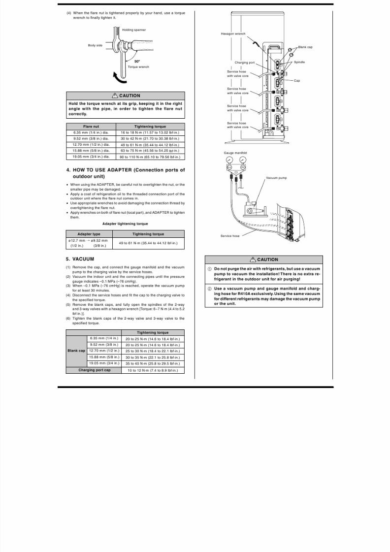
6 Do not purge the air with refrigerants but use a vacuum pump to vacuum the installation.
7 There is not extra refrigerant in the outdoor unit for air purging.
8 Use a vacuum pump for R410A exclusively.
9 Using the same vacuum pump for different refrigerants may damage the vacuum pump or the unit.
0 Use a clean gauge manifold and charging hose for R410A exclusively.
A If refrigerant leaks while work is being carried out, ventilate the area. If the refrigerant comes in contact with a flame,
it produces a toxic gas.
••••• Be careful not to scratch the room air conditioner when handling it.
••••• After installation, explain correct operation to the customer, using the operating manual.
••••• Let the customer keep this installation instruction sheet because it is used when the room air conditioner is serviced or moved.
Use
For outdoor unit drain piping
work
Q’ty
1
5
Name and Shape
Drain pipe
Drain cap
STANDARD PARTSThe following installation parts are furnished. Use them as required.
Use
For use when connecting
models 9–12 to outdoor port A
Q’ty
1
Name and Shape
Adapter assy
12.7 mm / 9.52 mm
(1/2 in.) (3/8 in.)
36 type only
OPERATING RANGE
Temperature Indoor air intake Outdoor air intake
Cooling
Maximum 90 °F DB 115 °F DB
Minimum 65 °F DB 32 °F DB
HeatingMaximum 86 °F DB or less 75 °F DB
Minimum — 14 °F DB
Indoor humidity about 80% or less
8/2/2019 Split Room AC Installation
http://slidepdf.com/reader/full/split-room-ac-installation 3/15
8/2/2019 Split Room AC Installation
http://slidepdf.com/reader/full/split-room-ac-installation 4/15
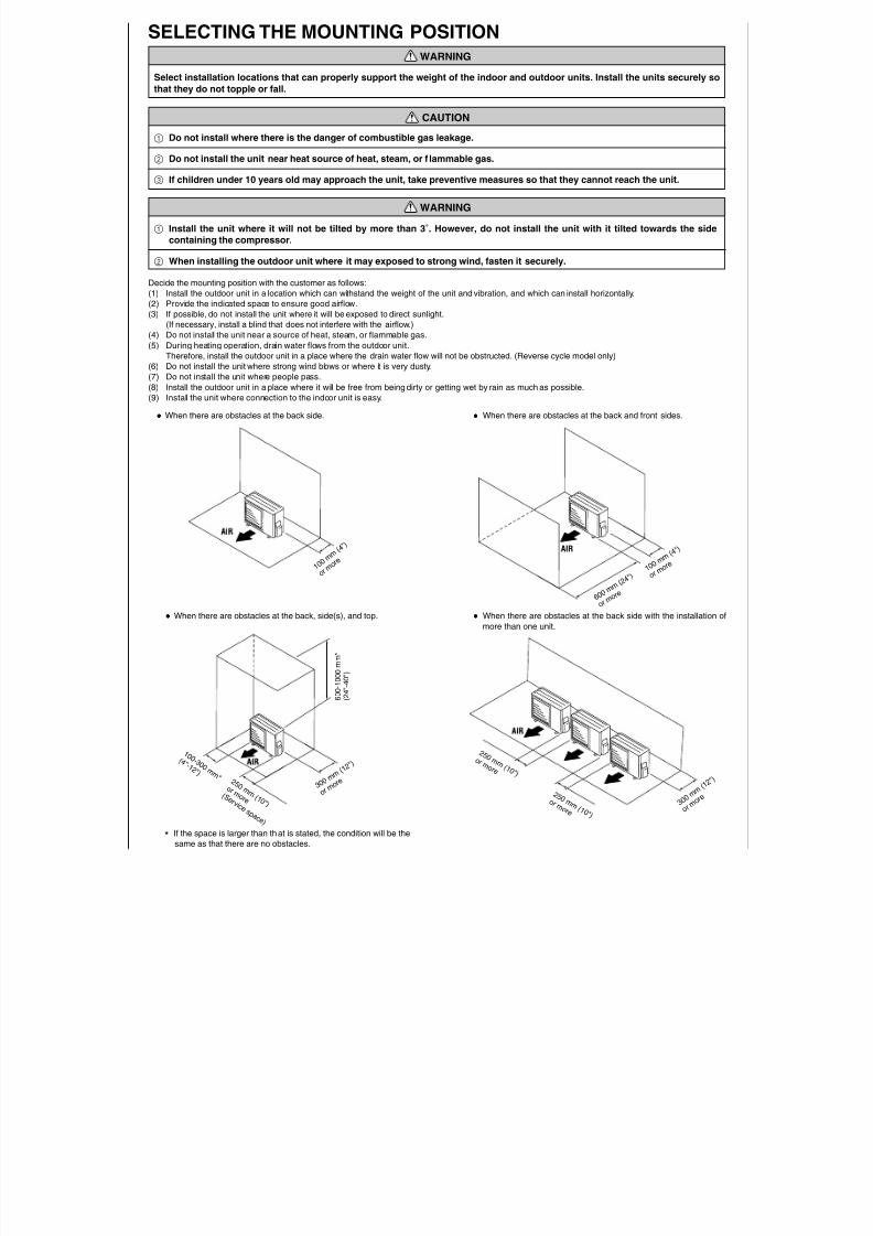
* If the space is larger than that is stated, the condition will be the
same as that there are no obstacles.
2 5 0 m m ( 1 0 " )
o r m o r e ( S e r v i c e s p a c e )
SELECTING THE MOUNTING POSITIONWARNING
Select installation locations that can properly support the weight of the indoor and outdoor units. Install the units securely sothat they do not topple or fall.
CAUTION
1 Do not install where there is the danger of combustible gas leakage.
2 Do not install the unit near heat source of heat, steam, or f lammable gas.
3 If children under 10 years old may approach the unit, take preventive measures so that they cannot reach the unit.
WARNING
1 Install the unit where it will not be tilted by more than 3˚. However, do not install the unit with it tilted towards the sidecontaining the compressor.
2 When installing the outdoor unit where it may exposed to strong wind, fasten it securely.
Decide the mounting position with the customer as follows:
(1) Install the outdoor unit in a location which can withstand the weight of the unit and vibration, and which can install horizontally.
(2) Provide the indicated space to ensure good airflow.(3) If possible, do not install the unit where it will be exposed to direct sunlight.
(If necessary, install a blind that does not interfere with the airflow.)
(4) Do not install the unit near a source of heat, steam, or flammable gas.
(5) During heating operation, drain water flows from the outdoor unit.
Therefore, install the outdoor unit in a place where the drain water flow will not be obstructed. (Reverse cycle model only)
(6) Do not install the unit where strong wind blows or where it is very dusty.
(7) Do not install the unit where people pass.
(8) Install the outdoor unit in a place where it will be free from being dirty or getting wet by rain as much as possible.
(9) Install the unit where connection to the indoor unit is easy.
••••• When there are obstacles at the back side. ••••• When there are obstacles at the back and front sides.
••••• When there are obstacles at the back side with the installation of
more than one unit.
AIR
1 0 0 m m
( 4 " )
o r m o r e
2 5 0
m m ( 1 0 " ) o r m o r e
2 5 0 m m ( 1 0 " )
o r m o r e
1 0 0 - 3 0 0 m m *
( 4 " - 1 2 " )
3 0 0 m
m ( 1 2 " )
o r m o
r e
600-1000mm*
(24"-40")
••••• When there are obstacles at the back, side(s), and top.
6 0 0 m
m ( 2 4 " )
o r m o
r e
1 0 0 m
m ( 4 " )
o r m o
r e
3 0 0 m
m ( 1 2 " )
o r m o r e
8/2/2019 Split Room AC Installation
http://slidepdf.com/reader/full/split-room-ac-installation 5/15
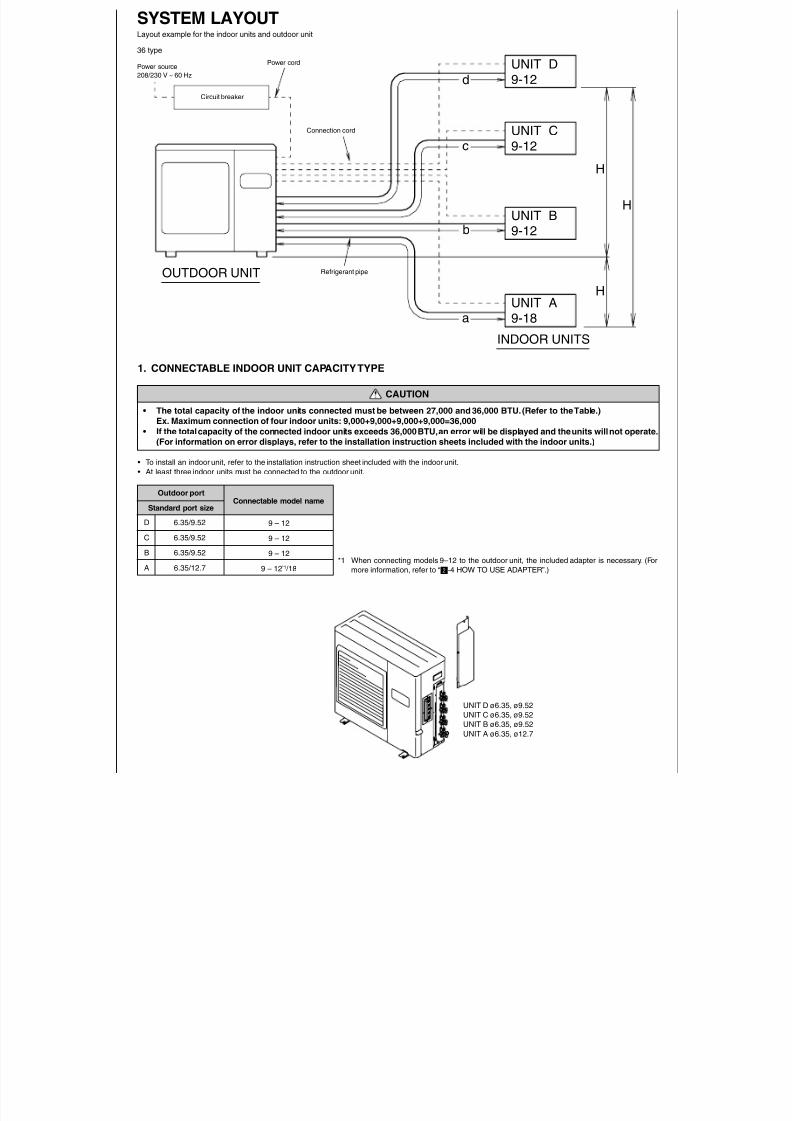
SYSTEM LAYOUTLayout example for the indoor units and outdoor unit
UNIT D
9-12
UNIT C
9-12
UNIT B
9-12
UNIT A
9-18a
b
c
d
H
H
H
Circuit breaker
OUTDOOR UNIT
Power source
208/230 V ~ 60 Hz
Power cord
Connection cord
Refrigerant pipe
36 type
INDOOR UNITS
Connectable model name
9 – 12
9 – 12
9 – 12
9 – 12*1 /18
D 6.35/9.52
C 6.35/9.52
B 6.35/9.52
A 6.35/12.7
1. CONNECTABLE INDOOR UNIT CAPACITY TYPE
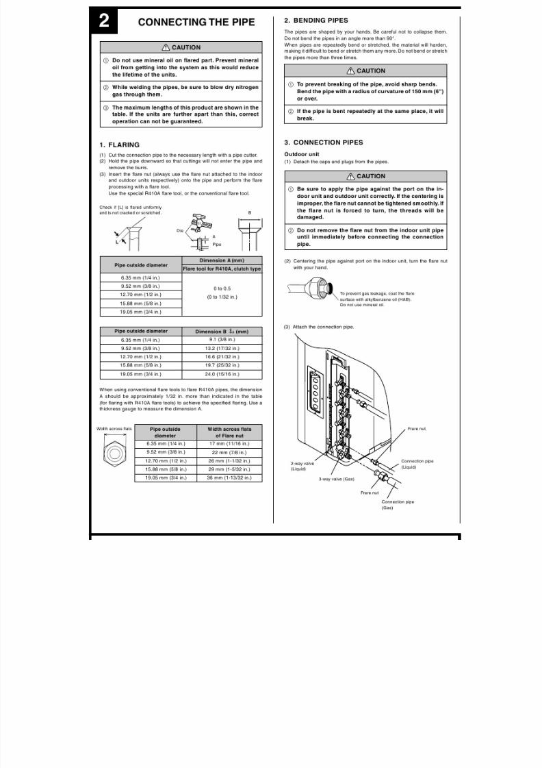
CAUTION
• The total capacity of the indoor units connected must be between 27,000 and 36,000 BTU. (Refer to the Table.)
Ex. Maximum connection of four indoor units: 9,000+9,000+9,000+9,000=36,000
• If the total capacity of the connected indoor units exceeds 36,000 BTU, an error will be displayed and the units will not operate.
(For information on error displays, refer to the installation instruction sheets included with the indoor units.)
• To install an indoor unit, refer to the installation instruction sheet included with the indoor unit.
• At least three indoor units must be connected to the outdoor unit.
*1 When connecting models 9–12 to the outdoor unit, the included adapter is necessary. (For
more information, refer to “2-4 HOW TO USE ADAPTER”.)
Outdoor port
Standard port size
UNIT D ø6.35, ø9.52
UNIT C ø6.35, ø9.52
UNIT B ø6.35, ø9.52
UNIT A ø6.35, ø12.7
8/2/2019 Split Room AC Installation
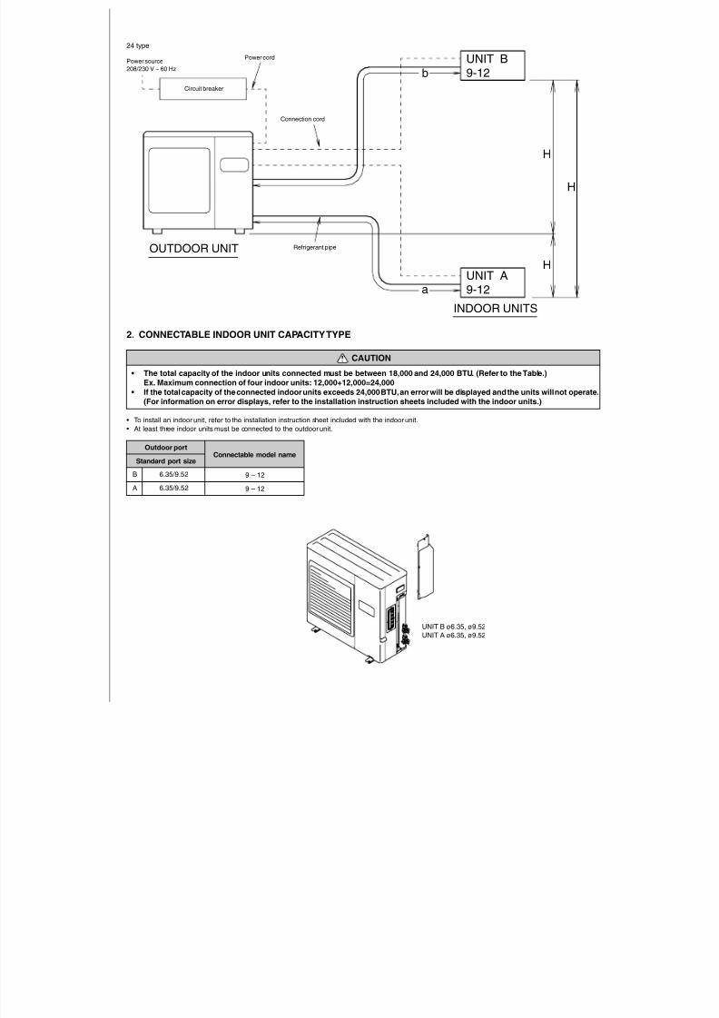
http://slidepdf.com/reader/full/split-room-ac-installation 6/15
UNIT B
9-12
UNIT A
9-12a
b
H
H
H
Circuit breaker
INDOOR UNITS
OUTDOOR UNIT
Power source
208/230 V ~ 60 Hz
Power cord
Connection cord
Refrigerant pipe
24 type
Connectable model name
9 – 12
9 – 12
B 6.35/9.52
A 6.35/9.52
2. CONNECTABLE INDOOR UNIT CAPACITY TYPE
CAUTION
• The total capacity of the indoor units connected must be between 18,000 and 24,000 BTU. (Refer to the Table.)
Ex. Maximum connection of four indoor units: 12,000+12,000=24,000
• If the total capacity of the connected indoor units exceeds 24,000 BTU, an error will be displayed and the units will not operate.
(For information on error displays, refer to the installation instruction sheets included with the indoor units.)
• To install an indoor unit, refer to the installation instruction sheet included with the indoor unit.
• At least three indoor units must be connected to the outdoor unit.
Outdoor port
Standard port size
UNIT B ø6.35, ø9.52UNIT A ø6.35, ø9.52
8/2/2019 Split Room AC Installation
http://slidepdf.com/reader/full/split-room-ac-installation 7/15
8/2/2019 Split Room AC Installation
http://slidepdf.com/reader/full/split-room-ac-installation 8/15
1
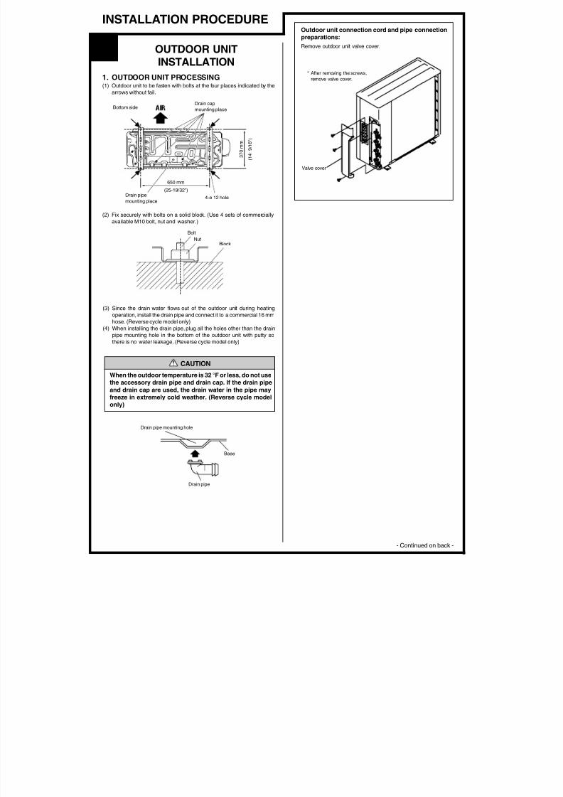
INSTALLATION PROCEDURE
OUTDOOR UNITINSTALLATION
1. OUTDOOR UNIT PROCESSING(1) Outdoor unit to be fasten with bolts at the four places indicated by the
arrows without fail.
(2) Fix securely with bolts on a solid block. (Use 4 sets of commercially
available M10 bolt, nut and washer.)
(3) Since the drain water flows out of the outdoor unit during heating
operation, install the drain pipe and connect it to a commercial 16 mm
hose. (Reverse cycle model only)
(4) When installing the drain pipe, plug all the holes other than the drain
pipe mounting hole in the bottom of the outdoor unit with putty so
there is no water leakage. (Reverse cycle model only)
Bottom sideDrain cap
mounting place
Drain pipe
mounting place
650 mm
(25-19/32")
4-ø 12 hole
370mm
(14-9/16")
Bolt
NutBlock
Valve cover
CAUTION
When the outdoor temperature is 32 °F or less, do not use
the accessory drain pipe and drain cap. If the drain pipe
and drain cap are used, the drain water in the pipe may
freeze in extremely cold weather. (Reverse cycle modelonly)
Drain pipe mounting hole
Base
Drain pipe
Outdoor unit connection cord and pipe connection
preparations:
Remove outdoor unit valve cover.
* After removing the screws,
remove valve cover.
- Continued on back -
8/2/2019 Split Room AC Installation
http://slidepdf.com/reader/full/split-room-ac-installation 9/15
8/2/2019 Split Room AC Installation
http://slidepdf.com/reader/full/split-room-ac-installation 10/15
3
8/2/2019 Split Room AC Installation
http://slidepdf.com/reader/full/split-room-ac-installation 11/15
3 POWER
WARNING
1 The rated voltage of this product is 208/230 V A.C. 60 Hz.
2 Before turning on verify that the voltage is within the187 V to 253 V range.
3 Always use a special branch circuit and install a spe-
cial receptacle to supply power to the air conditioner.
4 Use a special branch circuit breaker and receptaclematched to the capacity of the air conditioner.(Install in accordance with standard.)
5 Perform wiring work in accordance with standards sothat the air conditioner can be operated safely and posi-tively.
6 Install a leakage special branch circuit breaker in ac-cordance with the related laws and regulations andelectric company standards.
CAUTION
1 The power source capacity must be the sum of the airconditioner current and the current of other electricalappliances. When the current contracted capacity isinsufficient, change the contracted capacity.
2 When the voltage is low and the air conditioner is diffi-cult to start, contact the power company the voltageraised.
6. ADDITIONAL CHARGE
Refrigerant suitable for a total piping length of 164 ft is charged in the
outdoor unit at the factory.
When the piping is longer than 164 ft, additional charging is necessary.
For the additional amount, see the table below.
50 m 60 m 70 m
(164 ft) (197 ft) (230 ft)
None250 g 500 g 25 g/m
(8.8 oz) (17.6 oz) (0.9 oz/ft)
Total piping
length
Additional
refrigerant
CAUTION
1 After connecting the piping, check the all joints for gas
leakage with gas leak detector.
2 When inspecting gas leakage, always use the vacuum
pump for pressure. Do not use nitrogen gas.
7. GAS LEAKAGE INSPECTION
Gas
Liquid
CAUTION
1 When moving and installing the air conditioner, do not
mix gas other than the specified refrigerant (R410A)
inside the refrigerant cycle.
2 When charging the refrigerant R410A, always use an
electronic balance for refrigerant charging (to meas-
ure the refrigerant by weight).
3 When charging the refrigerant, take
into account the slight change in the
composition of the gas and liquid
phases, and always charge from the
liquid phase side whose composi-
tion is stable.
4 Add refrigerant from the charging valve after the com-
pletion of the work.
5 If the units are further apart than the maximum pipe
length, correct operation can not be guaranteed.
R410A
8/2/2019 Split Room AC Installation
http://slidepdf.com/reader/full/split-room-ac-installation 12/15
2 OUTDOOR UNIT 36 type
8/2/2019 Split Room AC Installation
http://slidepdf.com/reader/full/split-room-ac-installation 13/15
2. OUTDOOR UNIT
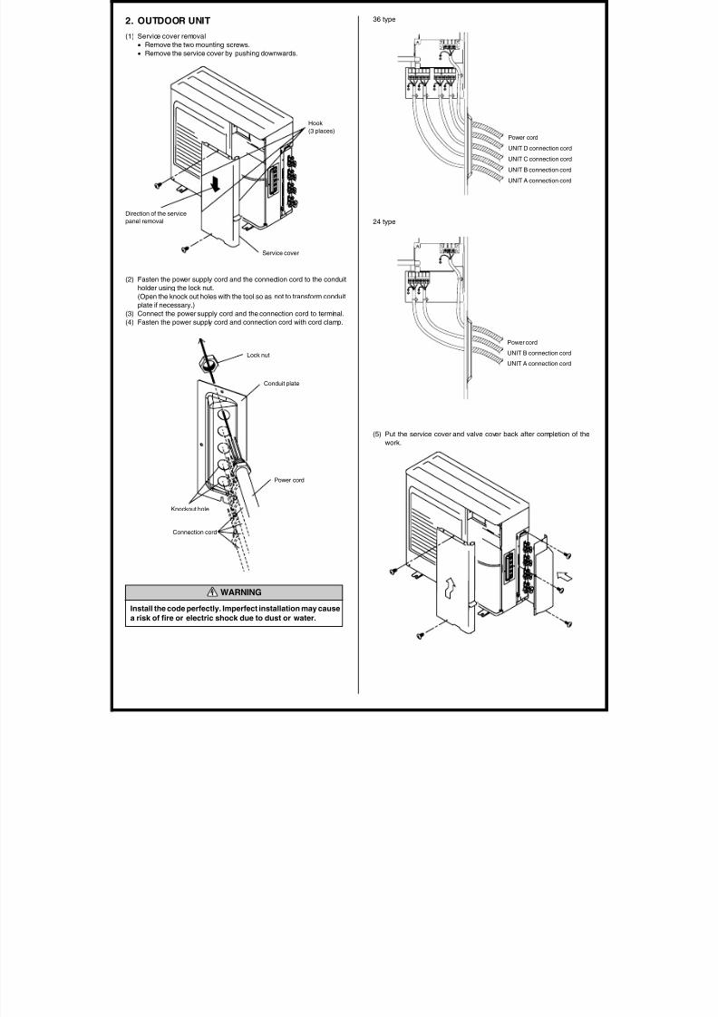
(1) Service cover removal
• Remove the two mounting screws.
• Remove the service cover by pushing downwards.
Direction of the service
panel removal
Service cover
Hook
(3 places)
(2) Fasten the power supply cord and the connection cord to the conduit
holder using the lock nut.
(Open the knock out holes with the tool so as not to transform conduit
plate if necessary.)
(3) Connect the power supply cord and the connection cord to terminal.
(4) Fasten the power supply cord and connection cord with cord clamp.
Power cord
Knockout hole
Connection cord
Lock nut
Power cord
UNIT D connection cord
UNIT C connection cord
UNIT B connection cord
UNIT A connection cord
36 type
24 type
(5) Put the service cover and valve cover back after completion of the
work.
Power cord
UNIT B connection cord
UNIT A connection cord
Conduit plate
WARNING
Install the code perfectly. Imperfect installation may cause
a risk of fire or electric shock due to dust or water.
5 TEST RUNNING
8/2/2019 Split Room AC Installation
http://slidepdf.com/reader/full/split-room-ac-installation 14/15
6 CUSTOMER GUIDANCE
Explain the following to the customer in accordance with the operating
manual:
(1) Starting and stopping method, operation switching, temperature
adjustment, timer, air flow adjustment, and other remote control unit
operations.(2) Air filter removal and cleaning.
(3) Give the operating manual and installation instruction sheet to the
customer.
5
1. Make a TEST RUN in accordance with the
installation instruction sheet for the indoor unit.
CHECK ITEMS
(1) INDOOR UNIT
(1) Is operation of each button on the remote control unit normal?
(2) Does each lamp light normally?
(3) Do the air flow-direction louver operate normally?
(4) Is the drain normal?
(5) Is there any abnormal noise and vibration during operation?
(2) OUTDOOR UNIT
(1) Is there any abnormal noise and vibration during operation?
(2) Will noise, wind, or drain water from the unit disturb the neighbors?
(3) Is there any gas leakage?
• Do not operate the air conditioner in the test running state for a long
time.
• For the operation method, refer to the operating manual and perform
operation check.
2. OUTDOOR UNIT LEDS
When a malfunction occurs in the outdoor unit, the LED on the circuit
board lights to indicate the error. Refer to the following table for the
description of each error according to the LED.
Error contents
Communication error
(Indoor unit – Outdoor unit)
Discharg pipe temperature sensor
Outdoor heat exchanger temperature sensor
Outdoor temperature sensor
2 way valve sensor
3 way valve sensor
Compressor temperature sensor
Heat sink temperature sensor
Pressure switch A abnormal
Pressure switch B abnormal
Connection indoor unit error
IPM error
Compressor rotor position cannot detectCompressor cannot operate
Outdoor fan abnormal
Communication error
(inverter - multi controller)
No error
LED
1 flash
2 flash
3 flash
4 flash
5 flash
6 flash
7 flash
8 flash
9 flash
10 flash
11 flash
12 flash
13 flash14 flash
15 flash
17 flash
lighting
TEST RUNNING
CAUTION
Always turn on the power 12 hours prior to the start of the
operation in order to ensure compressor protection
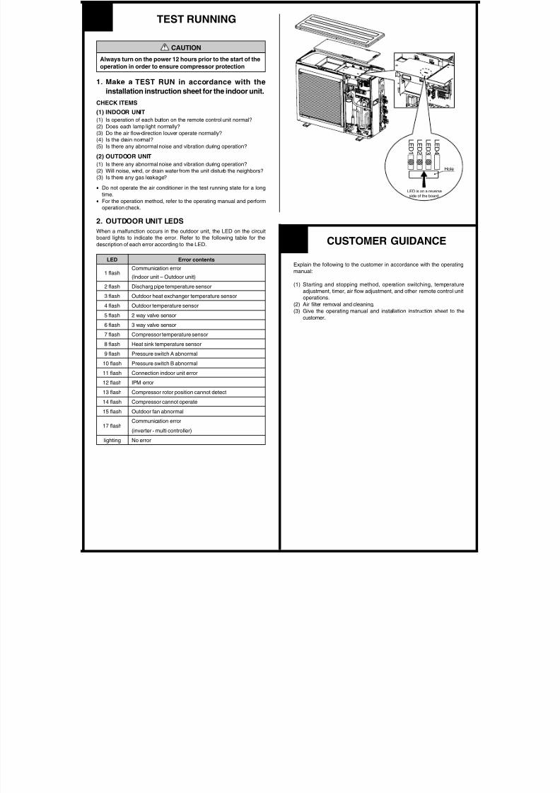
L E D4
L E D 3
L E D2
L E D1
Hole
LED is on a reverseside of the board.

8/2/2019 Split Room AC Installation
http://slidepdf.com/reader/full/split-room-ac-installation 15/15
PART NO. 9374747030