split-type, heat pump air conditioners no. ob379 service ... · pdf file3 refrigeration oil...
TRANSCRIPT
SERVICE MANUAL
CONTENTS
1. TECHNICAL CHANGES ····································22. PART NAMES AND FUNCTIONS······················63. SPECIFICATION·················································74. NOISE CRITERIA CURVES·······························95. OUTLINES AND DIMENSIONS ·······················106. WIRING DIAGRAM···········································117. REFRIGERANT SYSTEM DIAGRAM··············158. PERFORMANCE CURVES······························179. ACTUATOR CONTROL····································25
10. SERVICE FUNCTIONS·····································2611. TROUBLESHOOTING······································2612. DISASSEMBLY INSTRUCTIONS·····················4513. PARTS LIST······················································48
Wireless typeModels
No. OB379
SPLIT-TYPE, HEAT PUMP AIR CONDITIONERS
MUZ-GA25VA -MUZ-GA35VA -MUZ-GA25VAH -MUZ-GA35VAH - E1
E1
E1
E1
MUZ-GA25VA -MUZ-GA35VA -MUZ-GA25VAH -MUZ-GA35VAH - E1
E1
E1
E1
Indication ofmodel name
NOTE:This service manual describes technical data of the outdoor units.•As for indoor units MSZ-GA22VA- , MSZ-GA25VA- and MSZ-GA35VA- , refer to theservice manual OB378.
E1E1E1
HFCutilized
R410A
OB379 --1qxp 05.1.17 16:39 Page 1
2
1 TECHNICAL CHANGES
MUZ-A09YV - ➔ MUZ-GA25VA -MUZ-A09YVH - ➔ MUZ-GA25VAH - E1E1
E1E1
MUZ-A12YV - ➔ MUZ-GA35VA -MUZ-A12YVH - ➔ MUZ-GA35VAH - E1E1
E1E1
1.Indication of capacity has been changed.(BTU base ➔ kW base)2.Control method between indoor and outdoor unit has been changed.3.Power supply method has been changed (change to supply from outdoor unit).4.Terminal block for power supply has been added. 5.Power P.C. board has been changed.6.Inverter P.C. board has been changed.7.Refrigerant circuit has been changed.
• Compressor has been changed.(KNB073FBVH➔KNB065FDTH) • LEV has been removed and capillary tube has been added.• Bypass circuit for low outside temperature operation has been added.• Specification and position of muffler have been changed.• Path of outdoor heat exchanger has been changed.• 4-way valve and R.V. coil have been changed.• Stop valve has been changed.
8.Fan motor has been changed. (AC) 9.Shape of grille has been changed.
10.Shape of service panel has been changed.11.Shape of propeller has been changed.12.Quick Clean Kit has been added.13.Symbol on terminal block has been changed (to S1/S2/S3).
1.Indication of capacity has been changed.(BTU base ➔ kW base)2.Control method between indoor and outdoor unit has been changed.3.Power supply method has been changed (change to supply from outdoor unit).4.Terminal block for power supply has been added. 5.Power P.C. board has been changed.6.Inverter P.C. board has been changed.7.Refrigerant circuit has been changed.
• Compressor has been changed.(KNB092FAAH➔KNB073FDVH) • Specification and position of muffler have been changed.• Path of outdoor heat exchanger has been changed.• 4-way valve and R.V. coil have been changed.• Stop valve has been changed.
8.Fan motor has been changed.(AC➔DC)9.Shape of grille has been changed.
10.Shape of service panel has been changed.11.Shape of propeller has been changed. 12.Quick Clean Kit has been added.13.Symbol on terminal block has been changed (to S1/S2/S3).
OB379 --1qxp 05.1.17 16:39 Page 2
3
Refri
gera
tion
oil
Ref
riger
ant
New refrigerant
R410A
HFC-32: HFC-125 (50%:50%)
Pseudo-azeotropic refrigerant
Not included
A1/A1
72.6
-51.4
1.557
64
Non combustible
0
1730
From liquid phase in cylinder
Possible
Incompatible oil
Non
Non
Previous refrigerant
R22
R22 (100%)
Single refrigerant
Included
A1
86.5
-40.8
0.94
44.4
Non combustible
0.055
1700
Gas phase
Possible
Compatible oil
Light yellow
Non
Refrigerant
Composition (Ratio)
Refrigerant handling
Chlorine
Safety group (ASHRAE)
Molecular weight
Boiling point (:)
Steam pressure [25:](Mpa)
Saturated steam density [25:](Kg/K)
Combustibility
ODP w1
GWP w2
Refrigerant charge method
Additional charge on leakage
Kind
Color
Smell
w1 :Ozone Destruction Parameter : based on CFC-11w2 :Global Warmth Parameter : based on CO2
INFORMATION FOR THE AIR CONDITIONER WITH R410A REFRIGERANT• This room air conditioner adopts HFC refrigerant (R410A) which never destroys the ozone layer.• Pay particular attention to the following points, though the basic installation procedure is same as that for R22 air
conditioners.1As R410A has working pressure approximate 1.6 times as high as that of R22, some special tools and piping parts/
materials are required. Refer to the table below.2Take sufficient care not to allow water and other contaminations to enter the R410A refrigerant during storage and
installation, since it is more susceptible to contaminations than R22.3For refrigerant piping, use clean, pressure-proof parts/materials specifically designed for R410A. (Refer to 2. Refrigerant
piping.)4Composition change may occur in R410A since it is a mixed refrigerant. When charging, charge liquid refrigerant to prevent
composition change.
NOTE : The unit of pressure has been changed to MPa on the international system of units(SI unit system).The conversion factor is: 1(MPa [Gauge]) =10.2(kgf/ ff [Gauge])
New Specification Current Specification
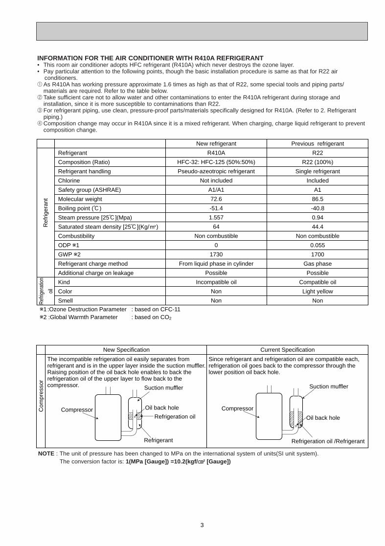
The incompatible refrigeration oil easily separates from refrigerant and is in the upper layer inside the suction muffler.Raising position of the oil back hole enables to back the refrigeration oil of the upper layer to flow back to the compressor.
Since refrigerant and refrigeration oil are compatible each, refrigeration oil goes back to the compressor through the lower position oil back hole.
Compressor
Suction muffler
Oil back hole
Refrigeration oil
Refrigerant
Compressor
Suction muffler
Oil back hole
Refrigeration oil /Refrigerant
Com
pres
sor
OB379 --1qxp 05.1.17 16:39 Page 3

4
-30 -20 -10 0 10 20 30 40 50 60-0.5
0.0
0.5
1.0
1.5
2.0
2.5
3.0
3.5
4.0(MPa [Gauge])
R410A
R22
Conversion chart of refrigerant temperature and pressure
Sat
urat
ed li
quid
pre
ssur
e
(:)
NOTE : The unit of pressure has been changed to MPa on the international system of units(SI unit system).
The conversion factor is: 1(MPa [Gauge]) =10.2(kgf/ ff [Gauge])
R410A tools Can R22 tools be used?
Gas leak detector
R410A has high pressures beyond the measurement range of existing gauges. Port diameters have been changed to prevent any other refrigerant from being charged into the unit.
Hose material and cap size have been changed to improve the pressure resistance.Dedicated for HFC refrigerant.
6.35 mm and 9.52 mm
Description
Clamp bar hole has been enlarged to reinforce the spring strength in the tool.
Provided for flaring work (to be used with R22 flare tool).Provided to prevent the back flow of oil. This adapter enables you to use vacuum pumps.It is difficult to measure R410A with a charging cylinder because the refrigerant bubbles due to high pressure and high-speed vaporization
No
No
No
Yes
Yes
New
New
New
Gauge manifold
Charge hose
Torque wrench
Flare tool
Flare gaugeVacuum pumpadapter
Electronic scale forrefrigerant charging
No : Not Substitutable for R410A Yes : Substitutable for R410A
No 12.7 mm
1.Tools dedicated for the air conditioner with R410A refrigerantThe following tools are required for R410A refrigerant. Some R22 tools can be substituted for R410A tools.The diameter of the service port on the stop valve in outdoor unit has been changed to prevent any other refrigerant being charged into the unit. Cap size has been changed from 7/16 UNF with 20 threads to 1/2 UNF with 20 threads.
2.Refrigerant piping1Specifications
Use the refrigerant pipes that meet the following specifications.
• Use a copper pipe or a copper-alloy seamless pipe with a thickness of 0.8 mm. Never use any pipe with a thickness less than 0.8mm, as the pressure resistance is insufficient.
Wallthickness
Outside diameterPipe
mm
For liquid
For gas
6.35
9.52
12.7
0.8 mm
0.8 mm
0.8 mm
Heat resisting foam plastic
Specific gravity 0.045 Thickness 8 mm
Insulation material
OB379 --1qxp 05.1.17 16:39 Page 4
5
Electronic scale for refrigerant charging
Outdoor unit
Refrigerant gas cylinderoperating valve
Refrigerant gas cylinderfor R410A with siphon
Refrigerant (liquid)
Service port
Gauge manifold valve (for R410A)
Union
Liquid pipe
Gas pipe
Stop valve
Indoor unit
Charge hose (for R410A)
R410A
Pipe diameter
mm
6.35
9.52
12.7
17
22
26
Dimension of flare nut
R22
17
22
24
2Flaring work and flare nutFlaring work for R410A pipe differs from that for R22 pipe.For details of flaring work, refer to Installation manual “FLARING WORK”.
3.Refrigerant oilApply the special refrigeration oil (accessories: packed with indoor unit) to the flare and the union seat surfaces.
4.Air purge• Do not discharge the refrigerant into the atmosphere.
Take care not to discharge refrigerant into the atmosphere during installation, reinstallation, or repairs to the refrigerant circuit.
• Use the vacuum pump for air purging for the purpose of environmental protection.
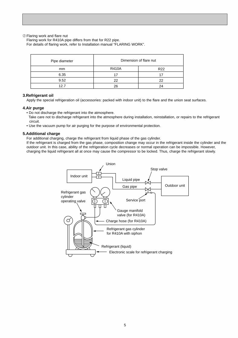
5.Additional chargeFor additional charging, charge the refrigerant from liquid phase of the gas cylinder. If the refrigerant is charged from the gas phase, composition change may occur in the refrigerant inside the cylinder and theoutdoor unit. In this case, ability of the refrigeration cycle decreases or normal operation can be impossible. However, charging the liquid refrigerant all at once may cause the compressor to be locked. Thus, charge the refrigerant slowly.
OB379 --1qxp 05.1.17 16:39 Page 5
6
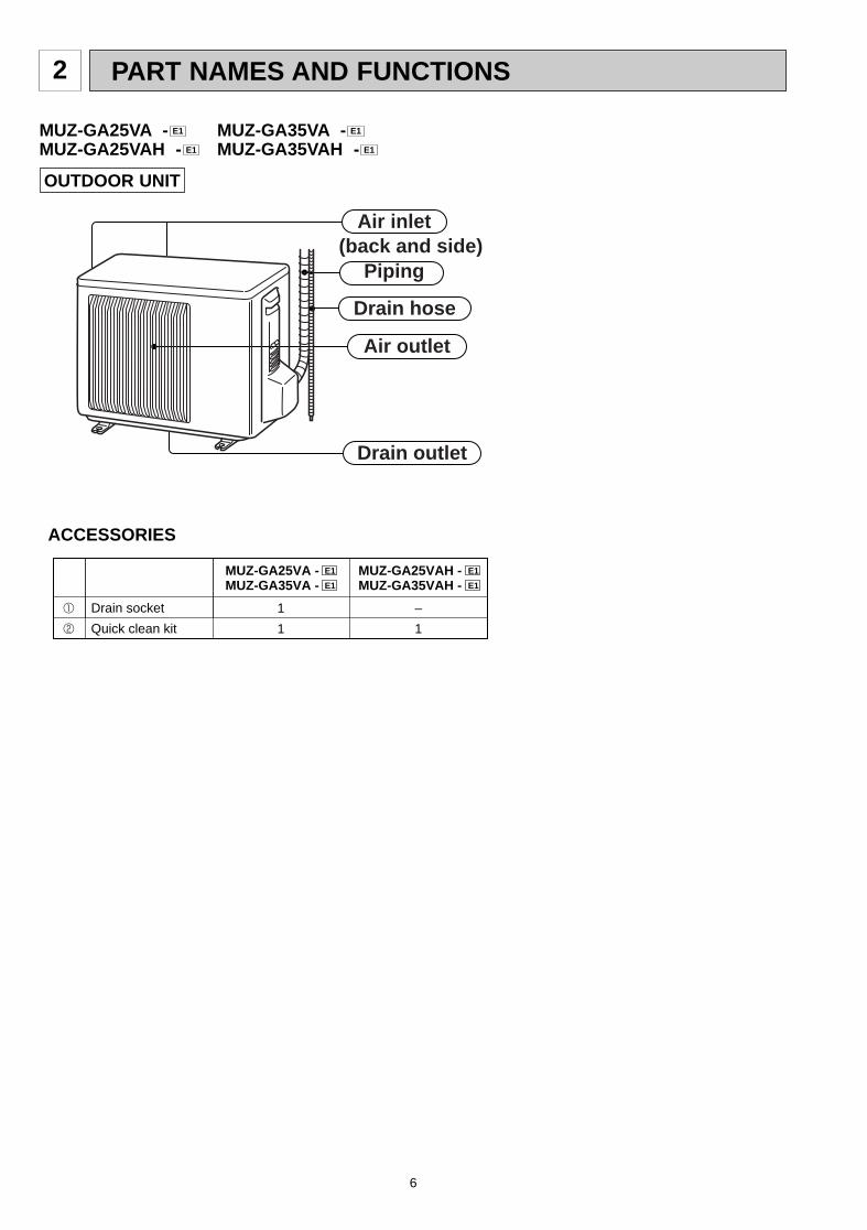
OUTDOOR UNIT
Air inlet
Air outlet
Drain outlet
Piping
Drain hose
(back and side)
ACCESSORIES
1 Drain socket 1
2 Quick clean kit 1
MUZ-GA25VA - E1
MUZ-GA35VA - E1
–
1
MUZ-GA25VAH - E1
MUZ-GA35VAH - E1
MUZ-GA25VA - MUZ-GA35VA -MUZ-GA25VAH - MUZ-GA35VAH - E1E1
E1E1
PART NAMES AND FUNCTIONS2
OB379 --1qxp 05.1.17 16:39 Page 6
7
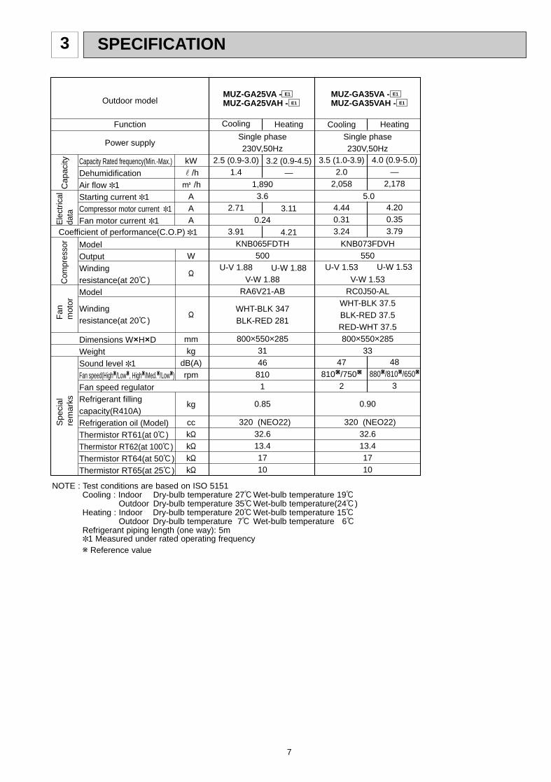
Single phase230V,50Hz
1,8903.6
0.24
KNB065FDTH500
V-W 1.88RA6V21-AB
WHT-BLK 347 BLK-RED 281
800o550o2853146
8101
0.85
320 (NEO22)32.613.41710
Cooling
2.5 (0.9-3.0)1.4
2.71
3.91
U-V 1.88
Heating
3.2 (0.9-4.5)—
3.11
4.21
U-W 1.88
MUZ-GA25VA - E1
E1 MUZ-GA25VAH -
Single phase230V,50Hz
5.0
KNB073FDVH550
V-W 1.53
RC0J50-ALWHT-BLK 37.5 BLK-RED 37.5RED-WHT 37.5800o550o285
33
0.90
320 (NEO22)32.613.41710
Cooling
3.5 (1.0-3.9)2.0
2,058
4.440.313.24
U-V 1.53
47810W/750W
2
Heating
4.0 (0.9-5.0)—
2,178
4.200.353.79
U-W 1.53
48880W/810W/650W
3
Outdoor model
Function
Power supply
Capacity Rated frequency(Min.-Max.)DehumidificationAir flow ✽1Starting current ✽1Compressor motor current ✽1Fan motor current ✽1
ModelOutputWindingresistance(at 20:)Model
Windingresistance(at 20:)
Dimensions WOHODWeightSound level ✽1Fan speed(HighW/LowW, HighW/Med.W/LowW)Fan speed regulatorRefrigerant fillingcapacity(R410A)Refrigeration oil (Model)Thermistor RT61(at 0:)Thermistor RT62(at 100:)Thermistor RT64(at 50:)Thermistor RT65(at 25:)
kWr/hK /h
AAA
✽1
W
"
"
mmkg
dB(A)rpm
kg
cck"k"k"k"
Com
pres
sor
Fan
m
otor
Spe
cial
rem
arks
Coefficient of performance(C.O.P)
Cap
acity
Ele
ctric
alda
ta
MUZ-GA35VA - E1
E1 MUZ-GA35VAH -
NOTE : Test conditions are based on ISO 5151Cooling : Indoor Dry-bulb temperature 27:Wet-bulb temperature 19:
Outdoor Dry-bulb temperature 35:Wet-bulb temperature(24:)Heating : Indoor Dry-bulb temperature 20:Wet-bulb temperature 15:
Outdoor Dry-bulb temperature 7: Wet-bulb temperature 6:Refrigerant piping length (one way): 5m✽1 Measured under rated operating frequencyw Reference value
3 SPECIFICATION
OB379 --1qxp 05.1.17 16:39 Page 7
8
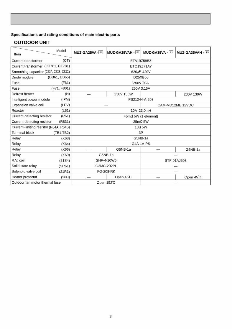
OUTDOOR UNIT
ModelItem
Current transformer
Current transformer
Smoothing capacitor
Diode module
Fuse
Fuse
Defrost heater
Intelligent power module
Expansion valve coil
Reactor
Current-detecting resistor
Current-detecting resistor
Current-limiting resistor
Terminal block
Relay
Relay
Relay
Relay
R.V. coil
Solid state relay
Solenoid valve coil
Heater protector
Outdoor fan motor thermal fuse
MUZ-GA25VA - E1
(CT)
(CT761, CT781)
(C63A, C63B, C63C)
(DB61, DB65)
(F61)
(F71, F801)
(H)
(IPM)
(LEV)
(L61)
(R61)
(R831)
(R64A, R64B)
(TB1,TB2)
(X63)
(X64)
(X66)
(X69)
(21S4)
(SR61)
(21R1)
(26H)
MUZ-GA25VAH - E1 MUZ-GA35VA - E1 MUZ-GA35VAH - E1
ETA19Z59BZ
ETQ19Z71AY
620+ 420V
D25XB60
250V 20A
250V 3.15A
PS21244-A-203
10A 23.0mH
25m" 5W
10" 5W
3P
G5NB-1a
G4A-1A-PS
—
—
—
230V 130W
G5NB-1a
Open 45:
—
—
—
230V 130W
G5NB-1a
Open 45:
45m" 5W (1 element)
CAM-MD12ME 12VDC
—
STF-01AJ503
—
—
—
—
G5NB-1a
SHF-4-10W5
G3MC-202PL
FQ-208-RK
Open 152:
Specifications and rating conditions of main electric parts
OB379 --1qxp 05.1.17 16:39 Page 8
9
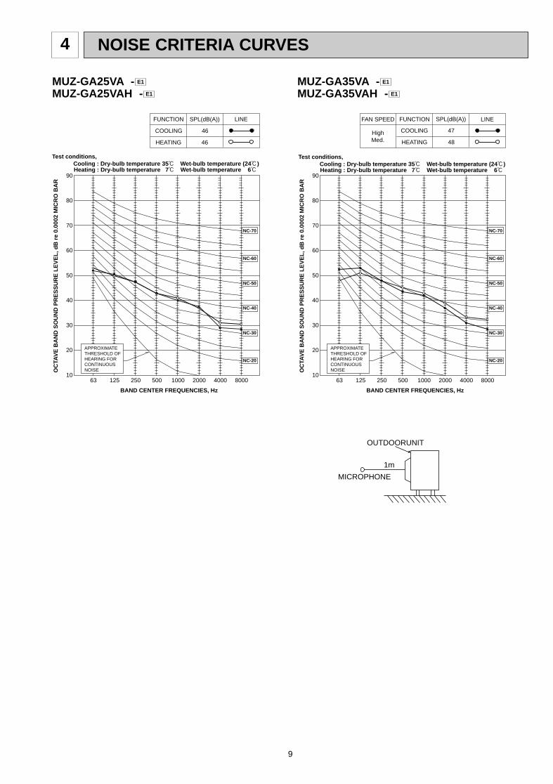
NOISE CRITERIA CURVES4
90
80
70
60
50
40
30
20
1063 125 250 500 1000 2000 4000 8000
NC-60
NC-50
NC-40
NC-30
NC-20
NC-70
OC
TAV
E B
AN
D S
OU
ND
PR
ES
SU
RE
LE
VE
L, d
B r
e 0.
0002
MIC
RO
BA
R
BAND CENTER FREQUENCIES, Hz
Test conditions, Cooling : Dry-bulb temperature 35: Wet-bulb temperature (24:)
APPROXIMATETHRESHOLD OF HEARING FORCONTINUOUSNOISE
COOLING
FUNCTION SPL(dB(A)) LINE
HEATING
46
46
Heating : Dry-bulb temperature 7: Wet-bulb temperature 6:
MUZ-GA25VA -MUZ-GA25VAH - E1
E1
90
80
70
60
50
40
30
20
1063 125 250 500 1000 2000 4000 8000
NC-60
NC-50
NC-40
NC-30
NC-20
NC-70
OC
TAV
E B
AN
D S
OU
ND
PR
ES
SU
RE
LE
VE
L, d
B r
e 0.
0002
MIC
RO
BA
R
BAND CENTER FREQUENCIES, Hz
APPROXIMATETHRESHOLD OF HEARING FORCONTINUOUSNOISE
COOLING
FUNCTION SPL(dB(A)) LINEFAN SPEED
HEATING
47
48
Test conditions, Cooling : Dry-bulb temperature 35: Wet-bulb temperature (24:) Heating : Dry-bulb temperature 7: Wet-bulb temperature 6:
OUTDOORUNIT
MICROPHONE
1m
HighMed.
MUZ-GA35VA -MUZ-GA35VAH - E1
E1
OB379 --1qxp 05.1.17 16:39 Page 9
10
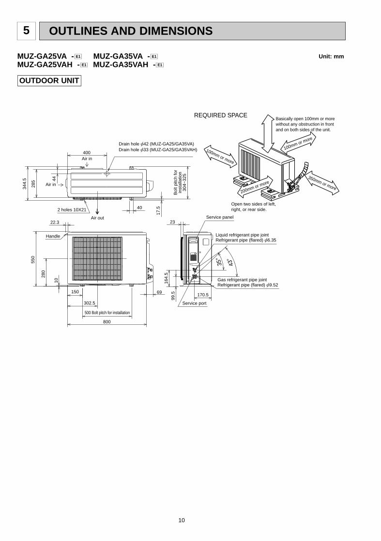
5 OUTLINES AND DIMENSIONS
10
69
800
302.5
500 Bolt pitch for installation
150
22.3
Handle
550
280
164.
5
99.5 170.5
23Service panel
Service port
285
344.
5 44
400Air in
Air out
Air in
17.5
Bol
t pitc
h fo
rin
stal
latio
n30
4~32
5
40
Liquid refrigerant pipe jointRefrigerant pipe (flared) [6.35
Gas refrigerant pipe jointRefrigerant pipe (flared) [9.52
43-
35-
2 holes 10X21
Drain hole [33 (MUZ-GA25/GA35VAH)
REQUIRED SPACEBasically open 100mm or more without any obstruction in front and on both sides of the unit.
350mm or more200mm or more
100mm or more
100mm or more
Open two sides of left, right, or rear side.
Drain hole [42 (MUZ-GA25/GA35VA)
Unit: mm
OUTDOOR UNIT
MUZ-GA25VA - MUZ-GA35VA -MUZ-GA25VAH - MUZ-GA35VAH - E1E1
E1E1
OB379 --1qxp 05.1.17 16:39 Page 10
11
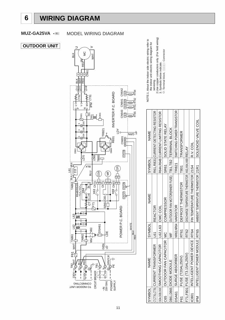
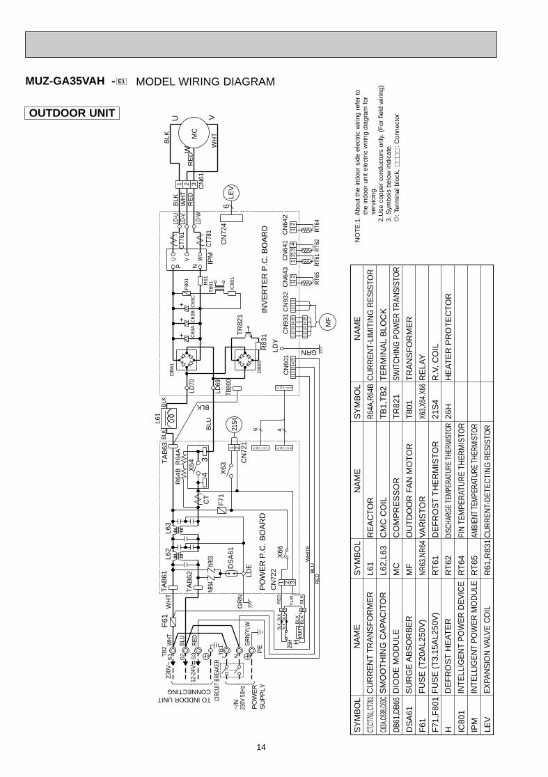
WIRING DIAGRAM6
OUTDOOR UNIT
SY
MB
OL
CT,CT
761,C
T781
C63A
,C63B
,C63C
C65
DB61
,DB6
5
DS
A61
F61
F71
,F80
1
IC80
1
IPM
SY
MB
OL
L61
L62,
L63
MC
MF
NR63
,NR6
4
RT
61
RT
62
RT
64
RT
65
SY
MB
OL
R61
,R83
1
R64A
,R64
B
SR
61
TB
1,T
B2
TR
821
T80
1
X63,
X64,
X69
21S
4
21R
1
N
AM
E
CU
RR
EN
T T
RA
NS
FO
RM
ER
SM
OO
TH
ING
CA
PA
CIT
OR
OU
TD
OO
R F
AN
CA
PA
CIT
OR
DIO
DE
MO
DU
LE
SU
RG
E A
BS
OR
BE
R
FU
SE
(T
20A
L250
V)
FU
SE
(T
3.15
AL2
50V
)
INTE
LLIG
EN
T P
OW
ER
DE
VIC
E
INTE
LLIG
EN
T P
OW
ER
MO
DU
LE
N
AM
E
RE
AC
TO
R
CM
C C
OIL
CO
MP
RE
SS
OR
OUT
DOO
R FA
N M
OTO
R(IN
NER
FUSE
)
VA
RIS
TO
R
DE
FR
OS
T T
HE
RM
IST
OR
DISC
HARG
E TE
MPER
ATUR
E TH
ERMI
STOR
FIN
TEM
PER
ATU
RE
THER
MIS
TOR
AMBI
ENT
TEM
PERA
TURE
THE
RMIS
TOR
NA
ME
CU
RR
ENT-
DET
ECTI
NG
RES
ISTO
R
CU
RR
EN
T-LI
MIT
ING
RE
SIS
TOR
SO
LID
STA
TE
RE
LAY
TE
RM
INA
L B
LOC
K
SWIT
CH
ING
PO
WER
TR
ANSI
STO
R
TR
AN
SF
OR
ME
R
RE
LAY
R.V
. CO
IL
SO
LEN
OID
VA
LVE
CO
IL
NO
TE
:1. A
bout
the
indo
or s
ide
elec
tric
wiri
ng r
efer
to
the
indo
or u
nit
elec
tric
wiri
ng d
iagr
am f
or
serv
icin
g.2.
Use
cop
per
cond
ucto
rs o
nly.
(F
or f
ield
wiri
ng)
3. S
ymbo
ls b
elow
indi
cate
./
: Ter
min
al b
lock
,
: C
onne
ctor
MODEL WIRING DIAGRAMMUZ-GA25VA - E1
PE
CIRC
UIT
BREA
KER
~/N
230V
50H
z
PO
WE
RS
UP
PLY
230V
~
12-2
4V
TO INDDOR UNITCONNECTING
WH
TR
64B
WH
T
BLU
RE
D
S2
S1
S3T
B2
R64
A
L N
GRN
/YLW
TB
1
RE
D
WH
ITE
BLU
++
+
CT
34
NR63
NR64
GR
NLD
EDS
A61
GRNLDY
X69
BLK
TAB
62X
64
L62
TAB
61F
61L6
3
T80
1
BLK
C63A
C63B
TR
821
LD70
DB
61
DB
65
LD69
TAB
63BL
K
P
WVU
N
R61
2CT
761
CT78
1IP
MC
N61
MC
U
W
WH
T
BLK
V
RE
DR
ED
BLK
WH
T1 3
LD-U
LD-W
LD-V
C63C
F80
1
IC80
1
INV
ER
TE
R P
.C. B
OA
RD
TB80
0
R83
1
CN
641
CN
642
CN
643
RT6
5
21
21
RT6
2R
T612
13
4
RT6
4
PO
WE
R P
.C. B
OA
RD
BLUL6
1
X63
F71
CN
727
CN
601
54
32
1C
N72
6C
N72
56
4
2121
S4CN
721
C65
SR
61
321 2 12 1
MF
21R1
CN92
3
CN77
1
OB379 --1qxp 05.1.17 16:39 Page 11
12
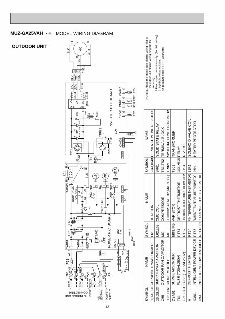
OUTDOOR UNIT
MUZ-GA25VAH - E1
SY
MB
OL
CT,CT
761,C
T781
C63A
,C63B
,C63C
C65
DB61
,DB6
5
DS
A61
F61
F71
,F80
1
H IC80
1
IPM
SY
MB
OL
L61
L62,
L63
MC
MF
NR63
,NR6
4
RT
61
RT
62
RT
64
RT
65
R61
,R83
1
SY
MB
OL
R64A
,R64
B
SR
61
TB
1,T
B2
TR
821
T80
1
X63,X
64,X6
6,X69
21S
4
21R
1
26H
N
AM
E
CU
RR
EN
T T
RA
NS
FO
RM
ER
SM
OO
TH
ING
CA
PA
CIT
OR
OU
TD
OO
R F
AN
CA
PA
CIT
OR
DIO
DE
MO
DU
LE
SU
RG
E A
BS
OR
BE
R
FU
SE
(T
20A
L250
V)
FU
SE
(T
3.15
AL2
50V
)
DE
FR
OS
T H
EA
TE
R
INTE
LLIG
EN
T P
OW
ER
DE
VIC
E
INTE
LLIG
EN
T P
OW
ER
MO
DU
LE
N
AM
E
RE
AC
TO
R
CM
C C
OIL
CO
MP
RE
SS
OR
OUT
DOO
R FA
N M
OTO
R(IN
NER
FUSE
)
VA
RIS
TO
R
DE
FR
OS
T T
HE
RM
IST
OR
DISC
HARG
E TE
MPER
ATUR
E TH
ERMI
STOR
FIN
TEM
PER
ATU
RE
THER
MIS
TOR
AMBI
ENT
TEM
PERA
TURE
THE
RMIS
TOR
CU
RR
ENT-
DET
ECTI
NG
RES
ISTO
R
NA
ME
CU
RR
EN
T-LI
MIT
ING
RE
SIS
TOR
SO
LID
STA
TE
RE
LAY
TE
RM
INA
L B
LOC
K
SWIT
CH
ING
PO
WER
TR
ANSI
STO
R
TR
AN
SF
OR
ME
R
RE
LAY
R.V
. CO
IL
SO
LEN
OID
VA
LVE
CO
IL
HE
AT
ER
PR
OT
EC
TO
R
NO
TE
:1. A
bout
the
indo
or s
ide
elec
tric
wiri
ng r
efer
to
the
indo
or u
nit
elec
tric
wiri
ng d
iagr
am f
or
serv
icin
g.2.
Use
cop
per
cond
ucto
rs o
nly.
(F
or f
ield
wiri
ng)
3. S
ymbo
ls b
elow
indi
cate
./
: Ter
min
al b
lock
,
: C
onne
ctor
MODEL WIRING DIAGRAM
PE
CIRC
UIT
BREA
KER
~/N
230V
50H
z
PO
WE
RS
UP
PLY
230V
~
12-2
4V
TO INDDOR UNITCONNECTING
RE
DB
LUW
HIT
E
GRN
/YLW
TB1
L N
R64
A
TB
2
S3
S1
S2
RE
D
BLU
WH
TR
64B
WH
T
H26H
++
+
CT
34
NR64
NR63
GR
ND
SA
61
LDE
LDY
GRN
X69
12
CN77
1
21R1
CN92
32 1
46
CN
725
CN
727
CN
726
C65
SR
61
31 2M
F
31 2X
66C
N72
21 2
YLW
BLK
BLK
BLK
BLK B
LKB
LK1 2
BLKRE
D
21
23
1CN
601
45
43
12
12
TB80
0
RT65
RT64
RT62
RT61
PO
WE
R P
.C. B
OA
RD
CN
643
CN
641
INV
ER
TE
R P
.C. B
OA
RD
CN
642
21S4
X63
CN72
11 2
IC80
1
F80
1C
63C
LD-V
LD-W
LD-U
31W
HT
BLK
RE
DR
ED
V
BLK
WH
T
W
U
MC
CN
61IP
MCT
781
CT76
12
R61
N
U V W
P
L61
BLK
R83
1
TA
B63
LD69
DB
65
DB
61
LD70
TR
821
C63
BC
63A
BLK
T80
1
L63
F61
TA
B61
L62
X64
F71
TA
B62
BLK
BLU
OB379 --1qxp 05.1.17 16:39 Page 12
13
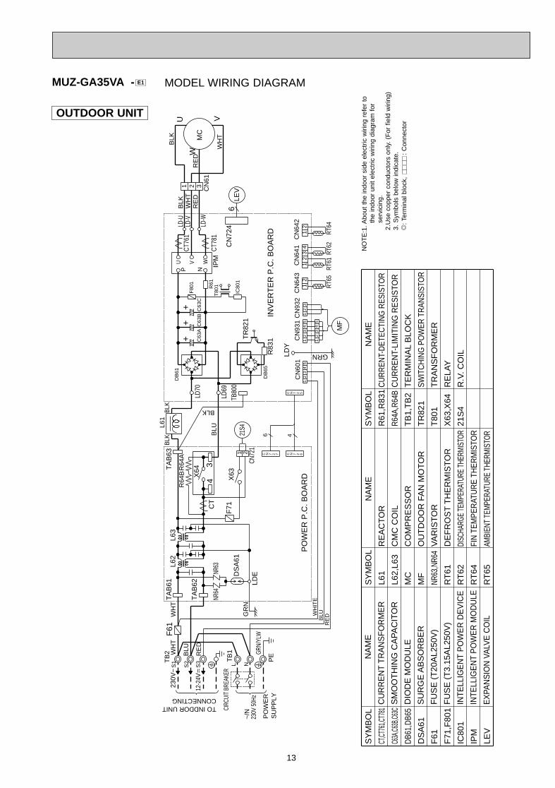
OUTDOOR UNIT
SY
MB
OL
CT,CT
761,C
T781
C63A
,C63B
,C63C
DB61
,DB6
5
DS
A61
F61
F71
,F80
1
IC80
1
IPM
LEV
SY
MB
OL
L61
L62,
L63
MC
MF
NR63
,NR6
4
RT
61
RT
62
RT
64
RT
65
SY
MB
OL
R61
,R83
1
R64A
,R64
B
TB
1,T
B2
TR
821
T80
1
X63
,X64
21S
4
N
AM
E
CU
RR
EN
T T
RA
NS
FO
RM
ER
SM
OO
TH
ING
CA
PA
CIT
OR
DIO
DE
MO
DU
LE
SU
RG
E A
BS
OR
BE
R
FU
SE
(T
20A
L250
V)
FU
SE
(T
3.15
AL2
50V
)
INTE
LLIG
EN
T P
OW
ER
DE
VIC
E
INTE
LLIG
EN
T P
OW
ER
MO
DU
LE
EX
PAN
SIO
N V
ALV
E C
OIL
N
AM
E
RE
AC
TO
R
CM
C C
OIL
CO
MP
RE
SS
OR
OU
TD
OO
R F
AN
MO
TO
R
VA
RIS
TO
R
DE
FR
OS
T T
HE
RM
IST
OR
DISC
HARG
E TE
MPER
ATUR
E TH
ERMI
STOR
FIN
TEM
PER
ATU
RE
THER
MIS
TOR
AMBI
ENT
TEM
PERA
TURE
THE
RMIS
TOR
NA
ME
CU
RR
ENT-
DET
ECTI
NG
RES
ISTO
R
CU
RR
EN
T-LI
MIT
ING
RE
SIS
TOR
TE
RM
INA
L B
LOC
K
SWIT
CH
ING
PO
WER
TR
ANSI
STO
R
TR
AN
SF
OR
ME
R
RE
LAY
R.V
. CO
IL
NO
TE
:1. A
bout
the
indo
or s
ide
elec
tric
wiri
ng r
efer
to
the
indo
or u
nit
elec
tric
wiri
ng d
iagr
am f
or
serv
icin
g.2.
Use
cop
per
cond
ucto
rs o
nly.
(F
or f
ield
wiri
ng)
3. S
ymbo
ls b
elow
indi
cate
./
: Ter
min
al b
lock
,
: C
onne
ctor
MODEL WIRING DIAGRAMMUZ-GA35VA - E1
~/N
230V
~
230V
50H
z
CIRC
UIT
BREA
KER
PE
RE
DBLUW
HIT
E
GRN
/YLW
TB
1
PO
WE
RS
UP
PLY
L N
R64
A
TB
2
S3
S1
TO INDDOR UNITCONNECTING
S2
RE
D
BLUWH
TR
64B
WH
T
++
+
NR63
LDE
GRN
46
21
23
1
CN
601
45
31
24
5
32
12
45
13
CN
931
CN
932
43
12
12
TB80
0
RT65
RT64
RT62
RT61
PO
WE
R P
.C. B
OA
RD
CN
643
CN
641
INV
ER
TE
R P
.C. B
OA
RD
CN
642
21S4
MF
X63
CN72
1
1 2IC
801
F80
1
C63
C
LD-V
LD-W
LD-U
31W
HT
BLK
RE
DR
ED
V
BLK
WH
T
W
U
MC
CN
61IP
MCT
781
CT76
12
CN
724
LEV
6
R61
N
U V W
P
L61
BLK
R83
1
TA
B63
3
LD69
DB
65
DB
61
LD70
TR
821
C63
BC
63A
BLK
T80
1
L63
NR64
DS
A61
F61
CT
LDY
TA
B61
L62
X64
4
F71
TA
B62
GR
N
BLK
BLU
C N 7 2 7 C N 7 2 6
C N 7 2 5
12-2
4V
OB379 --1qxp 05.1.17 16:39 Page 13
14
OUTDOOR UNIT
MUZ-GA35VAH - E1
SY
MB
OL
CT,CT
761,C
T781
C63A
,C63B
,C63C
DB61
,DB6
5
DS
A61
F61
F71
,F80
1
H IC80
1
IPM
LEV
SY
MB
OL
L61
L62,
L63
MC
MF
NR63
,NR6
4
RT
61
RT
62
RT
64
RT
65
R61
,R83
1
SY
MB
OL
R64A
,R64
B
TB
1,T
B2
TR
821
T80
1
X63,
X64,
X66
21S
4
26H
N
AM
E
CU
RR
EN
T T
RA
NS
FO
RM
ER
SM
OO
TH
ING
CA
PA
CIT
OR
DIO
DE
MO
DU
LE
SU
RG
E A
BS
OR
BE
R
FU
SE
(T
20A
L250
V)
FU
SE
(T
3.15
AL2
50V
)
DE
FR
OS
T H
EA
TE
R
INTE
LLIG
EN
T P
OW
ER
DE
VIC
E
INTE
LLIG
EN
T P
OW
ER
MO
DU
LE
EX
PAN
SIO
N V
ALV
E C
OIL
N
AM
E
RE
AC
TO
R
CM
C C
OIL
CO
MP
RE
SS
OR
OU
TD
OO
R F
AN
MO
TO
R
VA
RIS
TO
R
DE
FR
OS
T T
HE
RM
IST
OR
DISC
HARG
E TE
MPER
ATUR
E TH
ERMI
STOR
FIN
TEM
PER
ATU
RE
THER
MIS
TOR
AMBI
ENT
TEM
PERA
TURE
THE
RMIS
TOR
CU
RR
ENT-
DET
ECTI
NG
RES
ISTO
R
NA
ME
CU
RR
EN
T-LI
MIT
ING
RE
SIS
TOR
TE
RM
INA
L B
LOC
K
SWIT
CH
ING
PO
WER
TR
ANSI
STO
R
TR
AN
SF
OR
ME
R
RE
LAY
R.V
. CO
IL
HE
AT
ER
PR
OT
EC
TO
R
NO
TE
:1. A
bout
the
indo
or s
ide
elec
tric
wiri
ng r
efer
to
the
indo
or u
nit
elec
tric
wiri
ng d
iagr
am f
or
serv
icin
g.2.
Use
cop
per
cond
ucto
rs o
nly.
(F
or f
ield
wiri
ng)
3. S
ymbo
ls b
elow
indi
cate
./
: Ter
min
al b
lock
,
: C
onne
ctor
MODEL WIRING DIAGRAM
PE
CIRC
UIT
BREA
KER
~/N
230V
50H
z
PO
WE
RS
UP
PLY
230V
~
TO INDDOR UNITCONNECTING
RE
DB
LUW
HIT
E
GRN
/YLW
TB
1L N
R64
A
TB
2
S3
S1
S2
RED
BLU
WHT
R64
B
WH
T
H26
H
++
+
CT
43
NR64
NR63
GR
ND
SA
61
LDE
23
14
5
CN
601
LDY
GRN
MF
RT65
RT64
RT62
RT61
31
24
5
21
32
12
45
13
CN
931
CN
932
43
12
12
CN
643
CN
641
CN
642
31 2X
66C
N72
21 2
YLW
BLK
BLK
BLK
BLK B
LKB
LK1 2
BLK
RE
D
6 4
C N 7 2 7 C N 7 2 6
C N 7 2 5
TB80
0
PO
WE
R P
.C. B
OA
RD
INV
ER
TE
R P
.C. B
OA
RD
21S4
X63
CN
721
1 2IC
801
F80
1C
63C
LD-V
LD-W
LD-U
31W
HT
BLK
RE
DR
ED
V
BLK
WH
T
W
U
MC
CN
61IP
MCT
781
CT76
12
CN
724
LEV
6
R61
N
U V W
P
L61
BLK
R83
1
TA
B63
LD69
DB
65
DB
61
LD70
TR
821
C63
BC
63A
BLK
T80
1
L63
F61
TA
B61
L62
X64
F71
TA
B62
BLK
BLU
12-2
4V
OB379 --1qxp 05.1.17 16:39 Page 14
15
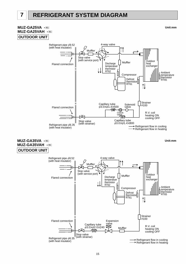
REFRIGERANT SYSTEM DIAGRAM7
OUTDOOR UNIT
Unit:mm
Outdoorheatexchanger
Flared connection
DefrostthermistorRT61
DischargetemperatuerthermistorRT62
Flared connection
Stop valve(with strainar)
Stop valve(with service port)
Refrigerant flow in cooling
Compressor
Muffler
Muffler
4-way valve
Refrigerant flow in heating
Refrigerant pipe [9.52(with heat insulator)
Refrigerant pipe [6.35(with heat insulator)
R.V. coilheating ONcooling OFF
Strainer#100
Capillary tube[3.0✕[1.4✕800
Check valve
Capillary tube[3.0✕[1.4✕500
Solenoid valve
Ambient temperature thermistorRT65
MUZ-GA25VA -MUZ-GA25VAH - E1
E1
OUTDOOR UNIT
Unit:mm
Outdoorheatexchanger
Flared connection
DefrostthermistorRT61
DischargetemperatuerthermistorRT62
Flared connection
Stop valve(with strainar)
Stop valve(with service port)
Capillary tube[3.0✕[2.0✕240
Refrigerant flow in cooling
Compressor
4-way valve
Refrigerant flow in heating
Refrigerant pipe [9.52(with heat insulator)
Refrigerant pipe [6.35(with heat insulator)
Expansionvalve
R.V. coilheating ONcooling OFF
Strainer#100
Muffler
Ambient temperature thermistorRT65
Muffler
Muffler
MUZ-GA35VA -MUZ-GA35VAH - E1
E1
OB379 --1qxp 05.1.17 16:39 Page 15
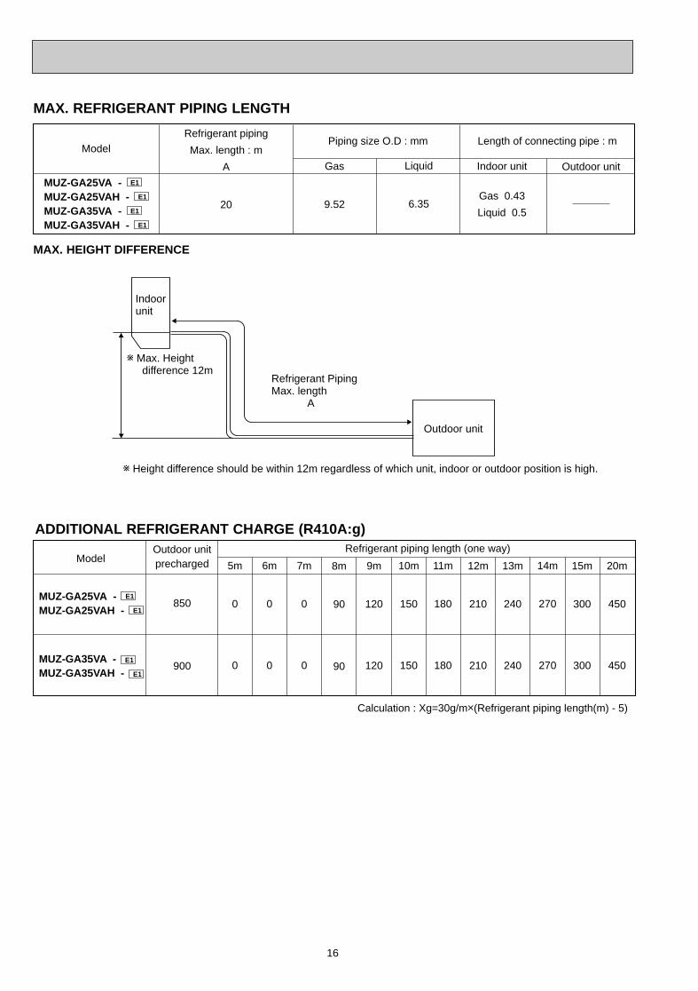
16
ADDITIONAL REFRIGERANT CHARGE (R410A:g)Outdoor unit precharged
850
900
14m
270
270
7m
0
0
6m
0
0
5m
0
0
11m
180
180
Model Refrigerant piping length (one way)
Calculation : Xg=30g/mo(Refrigerant piping length(m) - 5)
8m
90
90
9m
120
120
10m
150
150
12m
210
210
13m
240
240
15m
300
300
20m
450
450
MUZ-GA25VA - E1
MUZ-GA25VAH - E1
MUZ-GA35VA - E1 MUZ-GA35VAH - E1
Refrigerant PipingMax. length A
w Height difference should be within 12m regardless of which unit, indoor or outdoor position is high.
w Max. Heightdifference 12m
Indoorunit
Outdoor unit
MAX. HEIGHT DIFFERENCE
MAX. REFRIGERANT PIPING LENGTH
Refrigerant piping
Max. length : m
A
20
Indoor unit
Gas 0.43
Liquid 0.5
Gas
9.52
Liquid
6.35
Outdoor unit
Piping size O.D : mm Length of connecting pipe : mModel
MUZ-GA25VA - E1
MUZ-GA25VAH - E1
MUZ-GA35VA - E1
MUZ-GA35VAH - E1
OB379 --1qxp 05.1.17 16:39 Page 16

17
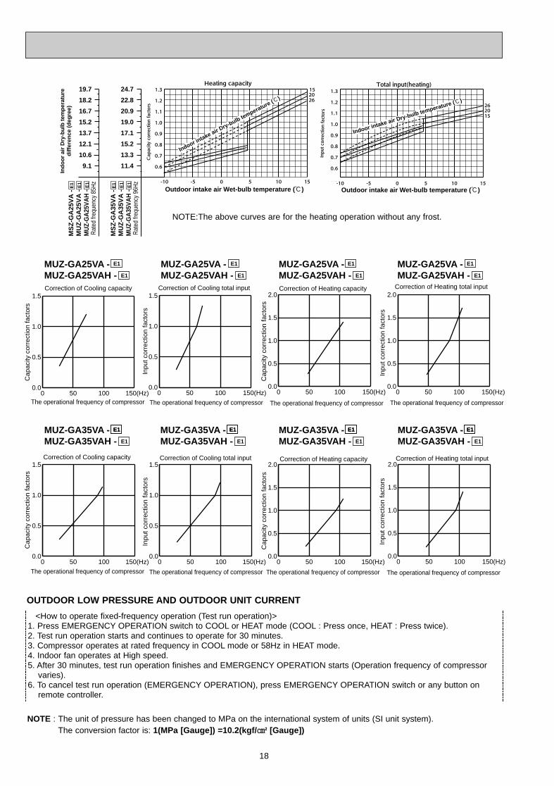
PERFORMANCE CURVES8
The standard data contained in these specifications apply only to the operation of the air conditioner under normal conditions.Since operating conditions vary according to the areas where these units are installed. The following information has beenprovided to clarify the operating characteristics of the air conditioner under the conditions indicated by the performance curve.(1) GUARANTEED VOLTAGE
207 ~ 253V, 50Hz(2) AIR FLOW
Air flow should be set at MAX.(3) MAIN READINGS
(1) Indoor intake air wet-bulb temperature : °C WB(2) Indoor outlet air wet-bulb temperature : °C WB(3) Outdoor intake air dry-bulb temperature : °C DB(4) Total input: W(5) Indoor intake air dry-bulb temperature : °C DB(6) Outdoor intake air wet-bulb temperature : °C WB(7) Total input : WIndoor air wet/dry-bulb temperature difference on the left side of the chart on next page shows the difference between theindoor intake air wet/dry-bulb temperature and the indoor outlet air wet/dry-bulb temperature for your reference at service.
}}
Cooling
Heating
How to measure the indoor air wet-bulb / dry-bulb temperature difference1. Attach at least 2 sets of wet and dry-bulb thermometers to the indoor air intake as shown in the figure, and at least 2 sets
of wet and dry-bulb thermometers to the indoor air outlet. The thermometers must be attached to the position where airspeed is high.
2. Attach at least 2 sets of wet and dry-bulb thermometers to the outdoor air intake.Cover the thermometers to prevent direct rays of the sun.
3. Check that the air filter is cleaned.4. Open windows and doors of room.5. Press the EMERGENCY OPERATION switch once (twice) to start the EMERGENCY COOL (HEAT) MODE.6. When system stabilizes after more than 15 minutes, measure temperature and take an average temperature.7. 10 minutes later, measure temperature again and check that the temperature does not change.
MUZ-GA25VA - MUZ-GA35VA -MUZ-GA25VAH - MUZ-GA35VAH - E1E1
E1E1
INDOOR UNIT OUTDOOR UNIT
Wet and dry-bulbthermometers
Wet and dry-bulbthermometers
Ind
oo
r ai
r W
et-b
ulb
tem
per
atu
red
iffe
ren
ce (
deg
ree)
Indoor intake air Wet-bulb temperature (:)
Outdoor intake air Dry-bulb temperature (:)
Indoor intake air Wet-bulb temperature (:)
Outdoor intake air Dry-bulb temperature (:)
MS
Z-G
A25
VA
- E
1
MU
Z-G
A25
VA
- E
1
MU
Z-G
A25
VA
H -
E1
6.4
5.8
5.3
4.9
4.4
3.9
9.1
8.3
7.6
6.8
6.1
5.5
MS
Z-G
A35
VA
- E
1
MU
Z-G
A35
VA
- E
1
MU
Z-G
A35
VA
H -
E1
Rat
ed fr
eque
ncy
65H
z
Rat
ed fr
eque
ncy
88H
z
OB379 --1qxp 05.1.17 16:39 Page 17
18
<How to operate fixed-frequency operation (Test run operation)> 1. Press EMERGENCY OPERATION switch to COOL or HEAT mode (COOL : Press once, HEAT : Press twice).2. Test run operation starts and continues to operate for 30 minutes.3. Compressor operates at rated frequency in COOL mode or 58Hz in HEAT mode.4. Indoor fan operates at High speed.5. After 30 minutes, test run operation finishes and EMERGENCY OPERATION starts (Operation frequency of compressor
varies).6. To cancel test run operation (EMERGENCY OPERATION), press EMERGENCY OPERATION switch or any button on
remote controller.
OUTDOOR LOW PRESSURE AND OUTDOOR UNIT CURRENT
NOTE : The unit of pressure has been changed to MPa on the international system of units (SI unit system).The conversion factor is: 1(MPa [Gauge]) =10.2(kgf/ ff [Gauge])
Correction of Cooling total input
Inpu
t cor
rect
ion
fact
ors
The operational frequency of compressor
Correction of Cooling capacity
Cap
acity
cor
rect
ion
fact
ors
The operational frequency of compressor
Correction of Cooling capacity
Cap
acity
cor
rect
ion
fact
ors
The operational frequency of compressor
Correction of Cooling total input
Inpu
t cor
rect
ion
fact
ors
The operational frequency of compressor
Correction of Heating total input
The operational frequency of compressor
Correction of Heating capacity
Cap
acity
cor
rect
ion
fact
ors
The operational frequency of compressor
Correction of Heating total input
Inpu
t cor
rect
ion
fact
ors
The operational frequency of compressor
Correction of Heating capacity
Cap
acity
cor
rect
ion
fact
ors
The operational frequency of compressor
Inpu
t cor
rect
ion
fact
ors
MUZ-GA25VA -MUZ-GA25VAH -
E1
E1
MUZ-GA25VA -MUZ-GA25VAH -
E1
E1
MUZ-GA25VA -MUZ-GA25VAH -
E1
E1
MUZ-GA25VA -MUZ-GA25VAH -
E1
E1
E1MUZ-GA35VA -MUZ-GA35VAH -
E1
E1
MUZ-GA35VA -MUZ-GA35VAH -
E1E1
E1
MUZ-GA35VA -MUZ-GA35VAH -
E1E1
E1
MUZ-GA35VA -MUZ-GA35VAH -
E1E1
E1
0 50 100 150(Hz)0.0
0.5
1.0
1.5
0 50 100 150(Hz)0.0
0.5
1.0
1.5
0 50 100 150(Hz)0.0
0.5
1.0
1.5
2.0
0 50 100 150(Hz)0.0
0.5
1.0
1.5
2.0
0 50 100 150(Hz)0.0
0.5
1.0
1.5
0 50 100 150(Hz)0.0
0.5
1.0
1.5
0 50 100 150(Hz)0.0
0.5
1.0
1.5
2.0
0 50 100 150(Hz)0.0
0.5
1.0
1.5
2.0
19.7
18.2
16.7
15.2
13.7
12.1
10.6
9.1
24.7
22.8
20.9
19.0
17.1
15.2
13.3
11.4
Ind
oo
r ai
r D
ry-b
ulb
tem
per
atu
red
iffe
ren
ce (
deg
ree)
Indoor intake air D
ry-bulb temperature (:)
Outdoor intake air Wet-bulb temperature (:) Outdoor intake air Wet-bulb temperature (:)
Indoor intake air Dry-bulb temperature (:)
Rat
ed fr
eque
ncy
85H
z
Rat
ed fr
eque
ncy
96H
z
MS
Z-G
A35
VA
- E
1
MU
Z-G
A35
VA
- E
1
MU
Z-G
A35
VA
H -
E1
MS
Z-G
A25
VA
- E
1
MU
Z-G
A25
VA
- E
1
MU
Z-G
A25
VA
H -
E1
NOTE:The above curves are for the heating operation without any frost.
OB379 --1qxp 05.1.17 16:39 Page 18
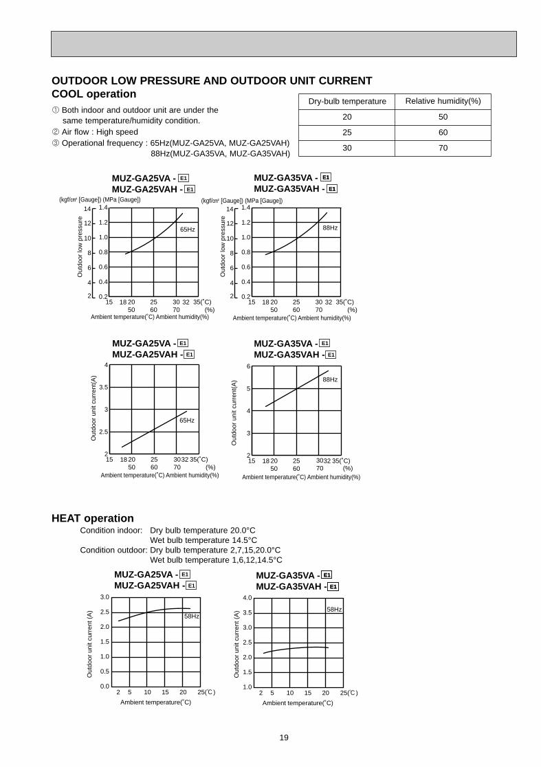
19
2 Air flow : High speed3 Operational frequency : 65Hz(MUZ-GA25VA, MUZ-GA25VAH)
88Hz(MUZ-GA35VA, MUZ-GA35VAH)
(kgf/F [Gauge]) (MPa [Gauge])
18 3215 2050
2560
3070 (%)
35(˚C)0.2
0.4
0.6
0.8
1.0
1.265Hz
2
4
6
8
10
12
14 1.4
Ambient temperature(˚C) Ambient humidity(%)
Out
door
low
pre
ssur
e
MUZ-GA25VA -MUZ-GA25VAH -
E1
E1
15 2050
2560
3070 (%)
35(˚C)2
2.5
3
3.5
4
65Hz
3218
Out
door
uni
t cur
rent
(A)
Ambient temperature(˚C) Ambient humidity(%)
(kgf/F [Gauge]) (MPa [Gauge])
Ambient temperature(˚C) Ambient humidity(%)
Ambient temperature(˚C) Ambient humidity(%)
18 3215 2050
2560
3070 (%)
35(˚C)0.2
0.4
0.6
0.8
1.0
1.288Hz
1.4
15 2050
2560
3070 (%)
35(˚C)2
3
4
5
6
88Hz
3218
Out
door
low
pre
ssur
e
Out
door
uni
t cur
rent
(A)
MUZ-GA25VA -MUZ-GA25VAH -
E1
E1
2
4
6
8
10
12
14
MUZ-GA35VA -MUZ-GA35VAH -
E1
E1
E1
E1
MUZ-GA35VA -MUZ-GA35VAH -
E1
E1
OUTDOOR LOW PRESSURE AND OUTDOOR UNIT CURRENTCOOL operation1 Both indoor and outdoor unit are under the
same temperature/humidity condition.
Dry-bulb temperature Relative humidity(%)
20 50
25 60
30 70
HEAT operationCondition indoor: Dry bulb temperature 20.0°C
Wet bulb temperature 14.5°CCondition outdoor: Dry bulb temperature 2,7,15,20.0°C
Wet bulb temperature 1,6,12,14.5°C
Out
door
uni
t cur
rent
(A
)
Out
door
uni
t cur
rent
(A
)
Ambient temperature(˚C) Ambient temperature(˚C)
MUZ-GA25VA -MUZ-GA25VAH -
E1
E1
MUZ-GA35VA -MUZ-GA35VAH -
E1
E1
E1
E1
3.0
2.5
2.0
1.5
1.0
0.5
0.02 5 10 15 20 25(:)
58Hz
4.0
3.5
3.0
2.5
2.0
1.5
1.02 5 10 15 20 25(:)
58Hz
OB379 --1qxp 05.1.17 16:39 Page 19
20
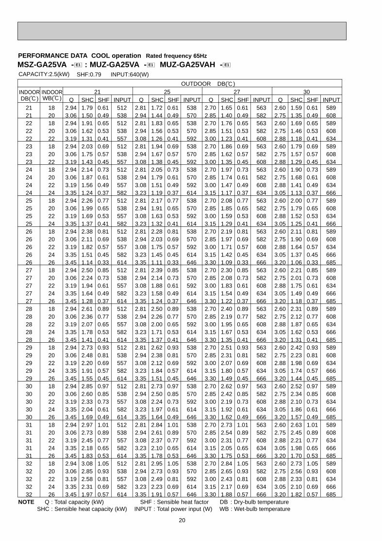
MSZ-GA25VA - : MUZ-GA25VA - MUZ-GA25VAH - E1E1E1
21 18 2.94 1.79 0.61 512 2.81 1.72 0.61 538 2.70 1.65 0.61 563 2.60 1.59 0.61 58921 20 3.06 1.50 0.49 538 2.94 1.44 0.49 570 2.85 1.40 0.49 582 2.75 1.35 0.49 60822 18 2.94 1.91 0.65 512 2.81 1.83 0.65 538 2.70 1.76 0.65 563 2.60 1.69 0.65 58922 20 3.06 1.62 0.53 538 2.94 1.56 0.53 570 2.85 1.51 0.53 582 2.75 1.46 0.53 60822 22 3.19 1.31 0.41 557 3.08 1.26 0.41 592 3.00 1.23 0.41 608 2.88 1.18 0.41 63423 18 2.94 2.03 0.69 512 2.81 1.94 0.69 538 2.70 1.86 0.69 563 2.60 1.79 0.69 58923 20 3.06 1.75 0.57 538 2.94 1.67 0.57 570 2.85 1.62 0.57 582 2.75 1.57 0.57 60823 22 3.19 1.43 0.45 557 3.08 1.38 0.45 592 3.00 1.35 0.45 608 2.88 1.29 0.45 63424 18 2.94 2.14 0.73 512 2.81 2.05 0.73 538 2.70 1.97 0.73 563 2.60 1.90 0.73 58924 20 3.06 1.87 0.61 538 2.94 1.79 0.61 570 2.85 1.74 0.61 582 2.75 1.68 0.61 60824 22 3.19 1.56 0.49 557 3.08 1.51 0.49 592 3.00 1.47 0.49 608 2.88 1.41 0.49 63424 24 3.35 1.24 0.37 582 3.23 1.19 0.37 614 3.15 1.17 0.37 634 3.05 1.13 0.37 66625 18 2.94 2.26 0.77 512 2.81 2.17 0.77 538 2.70 2.08 0.77 563 2.60 2.00 0.77 58925 20 3.06 1.99 0.65 538 2.94 1.91 0.65 570 2.85 1.85 0.65 582 2.75 1.79 0.65 60825 22 3.19 1.69 0.53 557 3.08 1.63 0.53 592 3.00 1.59 0.53 608 2.88 1.52 0.53 63425 24 3.35 1.37 0.41 582 3.23 1.32 0.41 614 3.15 1.29 0.41 634 3.05 1.25 0.41 66626 18 2.94 2.38 0.81 512 2.81 2.28 0.81 538 2.70 2.19 0.81 563 2.60 2.11 0.81 58926 20 3.06 2.11 0.69 538 2.94 2.03 0.69 570 2.85 1.97 0.69 582 2.75 1.90 0.69 60826 22 3.19 1.82 0.57 557 3.08 1.75 0.57 592 3.00 1.71 0.57 608 2.88 1.64 0.57 63426 24 3.35 1.51 0.45 582 3.23 1.45 0.45 614 3.15 1.42 0.45 634 3.05 1.37 0.45 66626 26 3.45 1.14 0.33 614 3.35 1.11 0.33 646 3.30 1.09 0.33 666 3.20 1.06 0.33 68527 18 2.94 2.50 0.85 512 2.81 2.39 0.85 538 2.70 2.30 0.85 563 2.60 2.21 0.85 58927 20 3.06 2.24 0.73 538 2.94 2.14 0.73 570 2.85 2.08 0.73 582 2.75 2.01 0.73 60827 22 3.19 1.94 0.61 557 3.08 1.88 0.61 592 3.00 1.83 0.61 608 2.88 1.75 0.61 63427 24 3.35 1.64 0.49 582 3.23 1.58 0.49 614 3.15 1.54 0.49 634 3.05 1.49 0.49 66627 26 3.45 1.28 0.37 614 3.35 1.24 0.37 646 3.30 1.22 0.37 666 3.20 1.18 0.37 68528 18 2.94 2.61 0.89 512 2.81 2.50 0.89 538 2.70 2.40 0.89 563 2.60 2.31 0.89 58928 20 3.06 2.36 0.77 538 2.94 2.26 0.77 570 2.85 2.19 0.77 582 2.75 2.12 0.77 60828 22 3.19 2.07 0.65 557 3.08 2.00 0.65 592 3.00 1.95 0.65 608 2.88 1.87 0.65 63428 24 3.35 1.78 0.53 582 3.23 1.71 0.53 614 3.15 1.67 0.53 634 3.05 1.62 0.53 66628 26 3.45 1.41 0.41 614 3.35 1.37 0.41 646 3.30 1.35 0.41 666 3.20 1.31 0.41 68529 18 2.94 2.73 0.93 512 2.81 2.62 0.93 538 2.70 2.51 0.93 563 2.60 2.42 0.93 58929 20 3.06 2.48 0.81 538 2.94 2.38 0.81 570 2.85 2.31 0.81 582 2.75 2.23 0.81 60829 22 3.19 2.20 0.69 557 3.08 2.12 0.69 592 3.00 2.07 0.69 608 2.88 1.98 0.69 63429 24 3.35 1.91 0.57 582 3.23 1.84 0.57 614 3.15 1.80 0.57 634 3.05 1.74 0.57 66629 26 3.45 1.55 0.45 614 3.35 1.51 0.45 646 3.30 1.49 0.45 666 3.20 1.44 0.45 68530 18 2.94 2.85 0.97 512 2.81 2.73 0.97 538 2.70 2.62 0.97 563 2.60 2.52 0.97 58930 20 3.06 2.60 0.85 538 2.94 2.50 0.85 570 2.85 2.42 0.85 582 2.75 2.34 0.85 60830 22 3.19 2.33 0.73 557 3.08 2.24 0.73 592 3.00 2.19 0.73 608 2.88 2.10 0.73 63430 24 3.35 2.04 0.61 582 3.23 1.97 0.61 614 3.15 1.92 0.61 634 3.05 1.86 0.61 66630 26 3.45 1.69 0.49 614 3.35 1.64 0.49 646 3.30 1.62 0.49 666 3.20 1.57 0.49 68531 18 2.94 2.97 1.01 512 2.81 2.84 1.01 538 2.70 2.73 1.01 563 2.60 2.63 1.01 58931 20 3.06 2.73 0.89 538 2.94 2.61 0.89 570 2.85 2.54 0.89 582 2.75 2.45 0.89 60831 22 3.19 2.45 0.77 557 3.08 2.37 0.77 592 3.00 2.31 0.77 608 2.88 2.21 0.77 63431 24 3.35 2.18 0.65 582 3.23 2.10 0.65 614 3.15 2.05 0.65 634 3.05 1.98 0.65 66631 26 3.45 1.83 0.53 614 3.35 1.78 0.53 646 3.30 1.75 0.53 666 3.20 1.70 0.53 68532 18 2.94 3.08 1.05 512 2.81 2.95 1.05 538 2.70 2.84 1.05 563 2.60 2.73 1.05 58932 20 3.06 2.85 0.93 538 2.94 2.73 0.93 570 2.85 2.65 0.93 582 2.75 2.56 0.93 60832 22 3.19 2.58 0.81 557 3.08 2.49 0.81 592 3.00 2.43 0.81 608 2.88 2.33 0.81 63432 24 3.35 2.31 0.69 582 3.23 2.23 0.69 614 3.15 2.17 0.69 634 3.05 2.10 0.69 66632 26 3.45 1.97 0.57 614 3.35 1.91 0.57 646 3.30 1.88 0.57 666 3.20 1.82 0.57 685
INDOOR INDOOR
CAPACITY:2.5(kW) INPUT:640(W)SHF:0.79
21OUTDOOR DB(:)
25 27 30WB(:) Q SHC SHF Q SHC SHF Q SHC SHF Q SHC SHFINPUT INPUT INPUT INPUTDB(:)
PERFORMANCE DATA COOL operation Rated frequency 65Hz
NOTE Q : Total capacity (kW) SHF : Sensible heat factor DB : Dry-bulb temperatureSHC : Sensible heat capacity (kW) INPUT : Total power input (W) WB : Wet-bulb temperature
OB379 --1qxp 05.1.17 16:39 Page 20
21
21 18 2.45 1.49 0.61 627 2.25 1.37 0.61 666 2.08 1.27 0.61 69121 20 2.58 1.26 0.49 653 2.40 1.18 0.49 685 2.23 1.09 0.49 72322 18 2.45 1.59 0.65 627 2.25 1.46 0.65 666 2.08 1.35 0.65 69122 20 2.58 1.36 0.53 653 2.40 1.27 0.53 685 2.23 1.18 0.53 72322 22 2.73 1.12 0.41 678 2.55 1.05 0.41 717 2.38 0.97 0.41 74223 18 2.45 1.69 0.69 627 2.25 1.55 0.69 666 2.08 1.43 0.69 69123 20 2.58 1.47 0.57 653 2.40 1.37 0.57 685 2.23 1.27 0.57 72323 22 2.73 1.23 0.45 678 2.55 1.15 0.45 717 2.38 1.07 0.45 74224 18 2.45 1.79 0.73 627 2.25 1.64 0.73 666 2.08 1.51 0.73 69124 20 2.58 1.57 0.61 653 2.40 1.46 0.61 685 2.23 1.36 0.61 72324 22 2.73 1.34 0.49 678 2.55 1.25 0.49 717 2.38 1.16 0.49 74224 24 2.88 1.06 0.37 704 2.70 1.00 0.37 736 2.55 0.94 0.37 76825 18 2.45 1.89 0.77 627 2.25 1.73 0.77 666 2.08 1.60 0.77 69125 20 2.58 1.67 0.65 653 2.40 1.56 0.65 685 2.23 1.45 0.65 72325 22 2.73 1.44 0.53 678 2.55 1.35 0.53 717 2.38 1.26 0.53 74225 24 2.88 1.18 0.41 704 2.70 1.11 0.41 736 2.55 1.05 0.41 76826 18 2.45 1.98 0.81 627 2.25 1.82 0.81 666 2.08 1.68 0.81 69126 20 2.58 1.78 0.69 653 2.40 1.66 0.69 685 2.23 1.54 0.69 72326 22 2.73 1.55 0.57 678 2.55 1.45 0.57 717 2.38 1.35 0.57 74226 24 2.88 1.29 0.45 704 2.70 1.22 0.45 736 2.55 1.15 0.45 76826 26 3.03 1.00 0.33 730 2.85 0.94 0.33 762 2.68 0.88 0.33 79427 18 2.45 2.08 0.85 627 2.25 1.91 0.85 666 2.08 1.76 0.85 69127 20 2.58 1.88 0.73 653 2.40 1.75 0.73 685 2.23 1.62 0.73 72327 22 2.73 1.66 0.61 678 2.55 1.56 0.61 717 2.38 1.45 0.61 74227 24 2.88 1.41 0.49 704 2.70 1.32 0.49 736 2.55 1.25 0.49 76827 26 3.03 1.12 0.37 730 2.85 1.05 0.37 762 2.68 0.99 0.37 79428 18 2.45 2.18 0.89 627 2.25 2.00 0.89 666 2.08 1.85 0.89 69128 20 2.58 1.98 0.77 653 2.40 1.85 0.77 685 2.23 1.71 0.77 72328 22 2.73 1.77 0.65 678 2.55 1.66 0.65 717 2.38 1.54 0.65 74228 24 2.88 1.52 0.53 704 2.70 1.43 0.53 736 2.55 1.35 0.53 76828 26 3.03 1.24 0.41 730 2.85 1.17 0.41 762 2.68 1.10 0.41 79429 18 2.45 2.28 0.93 627 2.25 2.09 0.93 666 2.08 1.93 0.93 69129 20 2.58 2.09 0.81 653 2.40 1.94 0.81 685 2.23 1.80 0.81 72329 22 2.73 1.88 0.69 678 2.55 1.76 0.69 717 2.38 1.64 0.69 74229 24 2.88 1.64 0.57 704 2.70 1.54 0.57 736 2.55 1.45 0.57 76829 26 3.03 1.36 0.45 730 2.85 1.28 0.45 762 2.68 1.20 0.45 79430 18 2.45 2.38 0.97 627 2.25 2.18 0.97 666 2.08 2.01 0.97 69130 20 2.58 2.19 0.85 653 2.40 2.04 0.85 685 2.23 1.89 0.85 72330 22 2.73 1.99 0.73 678 2.55 1.86 0.73 717 2.38 1.73 0.73 74230 24 2.88 1.75 0.61 704 2.70 1.65 0.61 736 2.55 1.56 0.61 76830 26 3.03 1.48 0.49 730 2.85 1.40 0.49 762 2.68 1.31 0.49 79431 18 2.45 2.47 1.01 627 2.25 2.27 1.01 666 2.08 2.10 1.01 69131 20 2.58 2.29 0.89 653 2.40 2.14 0.89 685 2.23 1.98 0.89 72331 22 2.73 2.10 0.77 678 2.55 1.96 0.77 717 2.38 1.83 0.77 74231 24 2.88 1.87 0.65 704 2.70 1.76 0.65 736 2.55 1.66 0.65 76831 26 3.03 1.60 0.53 730 2.85 1.51 0.53 762 2.68 1.42 0.53 79432 18 2.45 2.57 1.05 627 2.25 2.36 1.05 666 2.08 2.18 1.05 69132 20 2.58 2.39 0.93 653 2.40 2.23 0.93 685 2.23 2.07 0.93 72332 22 2.73 2.21 0.81 678 2.55 2.07 0.81 717 2.38 1.92 0.81 74232 24 2.88 1.98 0.69 704 2.70 1.86 0.69 736 2.55 1.76 0.69 76832 26 3.03 1.72 0.57 730 2.85 1.62 0.57 762 2.68 1.52 0.57 794
35 40 46
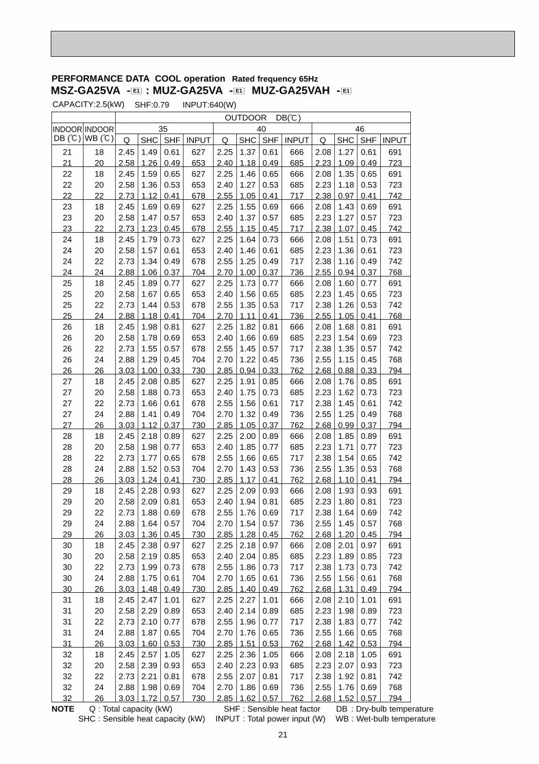
CAPACITY:2.5(kW) INPUT:640(W)SHF:0.79
OUTDOOR DB(:)INDOOR INDOORDB (:) WB (:) Q SHC SHF INPUT Q SHC SHF INPUT Q SHC SHF INPUT
PERFORMANCE DATA COOL operation Rated frequency 65Hz
NOTE Q : Total capacity (kW) SHF : Sensible heat factor DB : Dry-bulb temperatureSHC : Sensible heat capacity (kW) INPUT : Total power input (W) WB : Wet-bulb temperature
MSZ-GA25VA - : MUZ-GA25VA - MUZ-GA25VAH - E1E1E1
OB379 --1qxp 05.1.17 16:39 Page 21
22
21 18 4.11 2.39 0.58 864 3.94 2.28 0.58 907 3.78 2.19 0.58 950 3.64 2.11 0.58 99421 20 4.29 1.97 0.46 907 4.11 1.89 0.46 961 3.99 1.84 0.46 983 3.85 1.77 0.46 102622 18 4.11 2.55 0.62 864 3.94 2.44 0.62 907 3.78 2.34 0.62 950 3.64 2.26 0.62 99422 20 4.29 2.14 0.50 907 4.11 2.06 0.50 961 3.99 2.00 0.50 983 3.85 1.93 0.50 102622 22 4.46 1.70 0.38 940 4.31 1.64 0.38 999 4.20 1.60 0.38 1026 4.03 1.53 0.38 106923 18 4.11 2.71 0.66 864 3.94 2.60 0.66 907 3.78 2.49 0.66 950 3.64 2.40 0.66 99423 20 4.29 2.32 0.54 907 4.11 2.22 0.54 961 3.99 2.15 0.54 983 3.85 2.08 0.54 102623 22 4.46 1.87 0.42 940 4.31 1.81 0.42 999 4.20 1.76 0.42 1026 4.03 1.69 0.42 106924 18 4.11 2.88 0.70 864 3.94 2.76 0.70 907 3.78 2.65 0.70 950 3.64 2.55 0.70 99424 20 4.29 2.49 0.58 907 4.11 2.39 0.58 961 3.99 2.31 0.58 983 3.85 2.23 0.58 102624 22 4.46 2.05 0.46 940 4.31 1.98 0.46 999 4.20 1.93 0.46 1026 4.03 1.85 0.46 106924 24 4.69 1.59 0.34 983 4.52 1.54 0.34 1037 4.41 1.50 0.34 1069 4.27 1.45 0.34 112325 18 4.11 3.04 0.74 864 3.94 2.91 0.74 907 3.78 2.80 0.74 950 3.64 2.69 0.74 99425 20 4.29 2.66 0.62 907 4.11 2.55 0.62 961 3.99 2.47 0.62 983 3.85 2.39 0.62 102625 22 4.46 2.23 0.50 940 4.31 2.15 0.50 999 4.20 2.10 0.50 1026 4.03 2.01 0.50 106925 24 4.69 1.78 0.38 983 4.52 1.72 0.38 1037 4.41 1.68 0.38 1069 4.27 1.62 0.38 112326 18 4.11 3.21 0.78 864 3.94 3.07 0.78 907 3.78 2.95 0.78 950 3.64 2.84 0.78 99426 20 4.29 2.83 0.66 907 4.11 2.71 0.66 961 3.99 2.63 0.66 983 3.85 2.54 0.66 102626 22 4.46 2.41 0.54 940 4.31 2.32 0.54 999 4.20 2.27 0.54 1026 4.03 2.17 0.54 106926 24 4.69 1.97 0.42 983 4.52 1.90 0.42 1037 4.41 1.85 0.42 1069 4.27 1.79 0.42 112326 26 4.83 1.45 0.30 1037 4.69 1.41 0.30 1091 4.62 1.39 0.30 1123 4.48 1.34 0.30 115627 18 4.11 3.37 0.82 864 3.94 3.23 0.82 907 3.78 3.10 0.82 950 3.64 2.98 0.82 99427 20 4.29 3.00 0.70 907 4.11 2.88 0.70 961 3.99 2.79 0.70 983 3.85 2.70 0.70 102627 22 4.46 2.59 0.58 940 4.31 2.50 0.58 999 4.20 2.44 0.58 1026 4.03 2.33 0.58 106927 24 4.69 2.16 0.46 983 4.52 2.08 0.46 1037 4.41 2.03 0.46 1069 4.27 1.96 0.46 112327 26 4.83 1.64 0.34 1037 4.69 1.59 0.34 1091 4.62 1.57 0.34 1123 4.48 1.52 0.34 115628 18 4.11 3.54 0.86 864 3.94 3.39 0.86 907 3.78 3.25 0.86 950 3.64 3.13 0.86 99428 20 4.29 3.17 0.74 907 4.11 3.04 0.74 961 3.99 2.95 0.74 983 3.85 2.85 0.74 102628 22 4.46 2.77 0.62 940 4.31 2.67 0.62 999 4.20 2.60 0.62 1026 4.03 2.50 0.62 106928 24 4.69 2.35 0.50 983 4.52 2.26 0.50 1037 4.41 2.21 0.50 1069 4.27 2.14 0.50 112328 26 4.83 1.84 0.38 1037 4.69 1.78 0.38 1091 4.62 1.76 0.38 1123 4.48 1.70 0.38 115629 18 4.11 3.70 0.90 864 3.94 3.54 0.90 907 3.78 3.40 0.90 950 3.64 3.28 0.90 99429 20 4.29 3.34 0.78 907 4.11 3.21 0.78 961 3.99 3.11 0.78 983 3.85 3.00 0.78 102629 22 4.46 2.95 0.66 940 4.31 2.84 0.66 999 4.20 2.77 0.66 1026 4.03 2.66 0.66 106929 24 4.69 2.53 0.54 983 4.52 2.44 0.54 1037 4.41 2.38 0.54 1069 4.27 2.31 0.54 112329 26 4.83 2.03 0.42 1037 4.69 1.97 0.42 1091 4.62 1.94 0.42 1123 4.48 1.88 0.42 115630 18 4.11 3.87 0.94 864 3.94 3.70 0.94 907 3.78 3.55 0.94 950 3.64 3.42 0.94 99430 20 4.29 3.52 0.82 907 4.11 3.37 0.82 961 3.99 3.27 0.82 983 3.85 3.16 0.82 102630 22 4.46 3.12 0.70 940 4.31 3.01 0.70 999 4.20 2.94 0.70 1026 4.03 2.82 0.70 106930 24 4.69 2.72 0.58 983 4.52 2.62 0.58 1037 4.41 2.56 0.58 1069 4.27 2.48 0.58 112330 26 4.83 2.22 0.46 1037 4.69 2.16 0.46 1091 4.62 2.13 0.46 1123 4.48 2.06 0.46 115631 18 4.11 4.03 0.98 864 3.94 3.86 0.98 907 3.78 3.70 0.98 950 3.64 3.57 0.98 99431 20 4.29 3.69 0.86 907 4.11 3.54 0.86 961 3.99 3.43 0.86 983 3.85 3.31 0.86 102631 22 4.46 3.30 0.74 940 4.31 3.19 0.74 999 4.20 3.11 0.74 1026 4.03 2.98 0.74 106931 24 4.69 2.91 0.62 983 4.52 2.80 0.62 1037 4.41 2.73 0.62 1069 4.27 2.65 0.62 112331 26 4.83 2.42 0.50 1037 4.69 2.35 0.50 1091 4.62 2.31 0.50 1123 4.48 2.24 0.50 115632 18 4.11 4.19 1.02 864 3.94 4.02 1.02 907 3.78 3.86 1.02 950 3.64 3.71 1.02 99432 20 4.29 3.86 0.90 907 4.11 3.70 0.90 961 3.99 3.59 0.90 983 3.85 3.47 0.90 102632 22 4.46 3.48 0.78 940 4.31 3.36 0.78 999 4.20 3.28 0.78 1026 4.03 3.14 0.78 106932 24 4.69 3.10 0.66 983 4.52 2.98 0.66 1037 4.41 2.91 0.66 1069 4.27 2.82 0.66 112332 26 4.83 2.61 0.54 1037 4.69 2.53 0.54 1091 4.62 2.49 0.54 1123 4.48 2.42 0.54 1156
INDOOR INDOOR
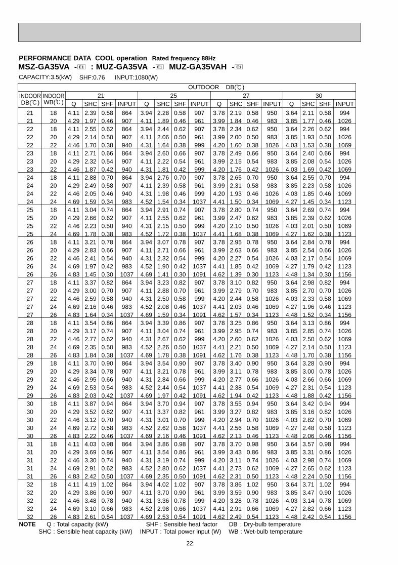
CAPACITY:3.5(kW) INPUT:1080(W)SHF:0.76
21OUTDOOR DB(:)
25 27 30WB(:) Q SHC SHF Q SHC SHF Q SHC SHF Q SHC SHFINPUT INPUT INPUT INPUTDB(:)
PERFORMANCE DATA COOL operation Rated frequency 88Hz
NOTE Q : Total capacity (kW) SHF : Sensible heat factor DB : Dry-bulb temperatureSHC : Sensible heat capacity (kW) INPUT : Total power input (W) WB : Wet-bulb temperature
MSZ-GA35VA - : MUZ-GA35VA - MUZ-GA35VAH - E1E1E1
OB379 --1qxp 05.1.17 16:39 Page 22
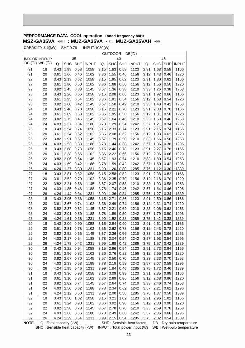
23
21 18 3.43 1.99 0.58 1058 3.15 1.83 0.58 1123 2.91 1.68 0.58 116621 20 3.61 1.66 0.46 1102 3.36 1.55 0.46 1156 3.12 1.43 0.46 122022 18 3.43 2.13 0.62 1058 3.15 1.95 0.62 1123 2.91 1.80 0.62 116622 20 3.61 1.80 0.50 1102 3.36 1.68 0.50 1156 3.12 1.56 0.50 122022 22 3.82 1.45 0.38 1145 3.57 1.36 0.38 1210 3.33 1.26 0.38 125323 18 3.43 2.26 0.66 1058 3.15 2.08 0.66 1123 2.91 1.92 0.66 116623 20 3.61 1.95 0.54 1102 3.36 1.81 0.54 1156 3.12 1.68 0.54 122023 22 3.82 1.60 0.42 1145 3.57 1.50 0.42 1210 3.33 1.40 0.42 125324 18 3.43 2.40 0.70 1058 3.15 2.21 0.70 1123 2.91 2.03 0.70 116624 20 3.61 2.09 0.58 1102 3.36 1.95 0.58 1156 3.12 1.81 0.58 122024 22 3.82 1.75 0.46 1145 3.57 1.64 0.46 1210 3.33 1.53 0.46 125324 24 4.03 1.37 0.34 1188 3.78 1.29 0.34 1242 3.57 1.21 0.34 129625 18 3.43 2.54 0.74 1058 3.15 2.33 0.74 1123 2.91 2.15 0.74 116625 20 3.61 2.24 0.62 1102 3.36 2.08 0.62 1156 3.12 1.93 0.62 122025 22 3.82 1.91 0.50 1145 3.57 1.79 0.50 1210 3.33 1.66 0.50 125325 24 4.03 1.53 0.38 1188 3.78 1.44 0.38 1242 3.57 1.36 0.38 129626 18 3.43 2.68 0.78 1058 3.15 2.46 0.78 1123 2.91 2.27 0.78 116626 20 3.61 2.38 0.66 1102 3.36 2.22 0.66 1156 3.12 2.06 0.66 122026 22 3.82 2.06 0.54 1145 3.57 1.93 0.54 1210 3.33 1.80 0.54 125326 24 4.03 1.69 0.42 1188 3.78 1.59 0.42 1242 3.57 1.50 0.42 129626 26 4.24 1.27 0.30 1231 3.99 1.20 0.30 1285 3.75 1.12 0.30 133927 18 3.43 2.81 0.82 1058 3.15 2.58 0.82 1123 2.91 2.38 0.82 116627 20 3.61 2.52 0.70 1102 3.36 2.35 0.70 1156 3.12 2.18 0.70 122027 22 3.82 2.21 0.58 1145 3.57 2.07 0.58 1210 3.33 1.93 0.58 125327 24 4.03 1.85 0.46 1188 3.78 1.74 0.46 1242 3.57 1.64 0.46 129627 26 4.24 1.44 0.34 1231 3.99 1.36 0.34 1285 3.75 1.27 0.34 133928 18 3.43 2.95 0.86 1058 3.15 2.71 0.86 1123 2.91 2.50 0.86 116628 20 3.61 2.67 0.74 1102 3.36 2.49 0.74 1156 3.12 2.31 0.74 122028 22 3.82 2.37 0.62 1145 3.57 2.21 0.62 1210 3.33 2.06 0.62 125328 24 4.03 2.01 0.50 1188 3.78 1.89 0.50 1242 3.57 1.79 0.50 129628 26 4.24 1.61 0.38 1231 3.99 1.52 0.38 1285 3.75 1.42 0.38 133929 18 3.43 3.09 0.90 1058 3.15 2.84 0.90 1123 2.91 2.61 0.90 116629 20 3.61 2.81 0.78 1102 3.36 2.62 0.78 1156 3.12 2.43 0.78 122029 22 3.82 2.52 0.66 1145 3.57 2.36 0.66 1210 3.33 2.19 0.66 125329 24 4.03 2.17 0.54 1188 3.78 2.04 0.54 1242 3.57 1.93 0.54 129629 26 4.24 1.78 0.42 1231 3.99 1.68 0.42 1285 3.75 1.57 0.42 133930 18 3.43 3.22 0.94 1058 3.15 2.96 0.94 1123 2.91 2.73 0.94 116630 20 3.61 2.96 0.82 1102 3.36 2.76 0.82 1156 3.12 2.55 0.82 122030 22 3.82 2.67 0.70 1145 3.57 2.50 0.70 1210 3.33 2.33 0.70 125330 24 4.03 2.33 0.58 1188 3.78 2.19 0.58 1242 3.57 2.07 0.58 129630 26 4.24 1.95 0.46 1231 3.99 1.84 0.46 1285 3.75 1.72 0.46 133931 18 3.43 3.36 0.98 1058 3.15 3.09 0.98 1123 2.91 2.85 0.98 116631 20 3.61 3.10 0.86 1102 3.36 2.89 0.86 1156 3.12 2.68 0.86 122031 22 3.82 2.82 0.74 1145 3.57 2.64 0.74 1210 3.33 2.46 0.74 125331 24 4.03 2.50 0.62 1188 3.78 2.34 0.62 1242 3.57 2.21 0.62 129631 26 4.24 2.12 0.50 1231 3.99 2.00 0.50 1285 3.75 1.87 0.50 133932 18 3.43 3.50 1.02 1058 3.15 3.21 1.02 1123 2.91 2.96 1.02 116632 20 3.61 3.24 0.90 1102 3.36 3.02 0.90 1156 3.12 2.80 0.90 122032 22 3.82 2.98 0.78 1145 3.57 2.78 0.78 1210 3.33 2.59 0.78 125332 24 4.03 2.66 0.66 1188 3.78 2.49 0.66 1242 3.57 2.36 0.66 129632 26 4.24 2.29 0.54 1231 3.99 2.15 0.54 1285 3.75 2.02 0.54 1339
35 40 46
CAPACITY:3.5(kW) INPUT:1080(W)SHF:0.76
OUTDOOR DB(:)INDOOR INDOORDB (:) WB (:) Q SHC SHF INPUT Q SHC SHF INPUT Q SHC SHF INPUT
PERFORMANCE DATA COOL operation Rated frequency 88Hz
NOTE Q : Total capacity (kW) SHF : Sensible heat factor DB : Dry-bulb temperatureSHC : Sensible heat capacity (kW) INPUT : Total power input (W) WB : Wet-bulb temperature
MSZ-GA35VA - : MUZ-GA35VA - MUZ-GA35VAH - E1E1E1
OB379 --1qxp 05.1.17 16:39 Page 23
24
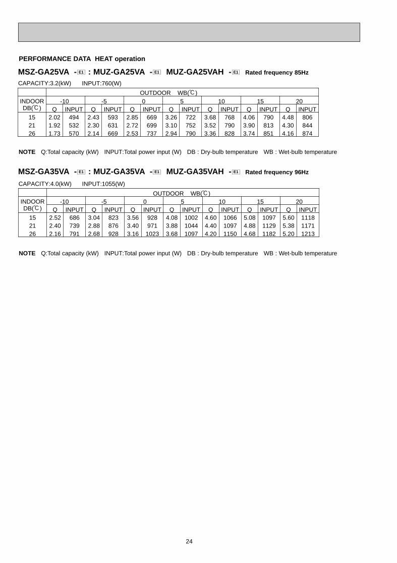
PERFORMANCE DATA HEAT operation
CAPACITY:3.2(kW) INPUT:760(W)
OUTDOOR WB(:)INDOOR -10 -5 0 5 10 15 20DB(:) Q INPUT Q INPUT Q INPUT Q INPUT Q INPUT Q INPUT Q INPUT
15 2.02 494 2.43 593 2.85 669 3.26 722 3.68 768 4.06 790 4.48 80621 1.92 532 2.30 631 2.72 699 3.10 752 3.52 790 3.90 813 4.30 84426 1.73 570 2.14 669 2.53 737 2.94 790 3.36 828 3.74 851 4.16 874
CAPACITY:4.0(kW) INPUT:1055(W)
OUTDOOR WB(:)INDOOR -10 -5 0 5 10 15 20DB(:) Q INPUT Q INPUT Q INPUT Q INPUT Q INPUT Q INPUT Q INPUT
15 2.52 686 3.04 823 3.56 928 4.08 1002 4.60 1066 5.08 1097 5.60 111821 2.40 739 2.88 876 3.40 971 3.88 1044 4.40 1097 4.88 1129 5.38 117126 2.16 791 2.68 928 3.16 1023 3.68 1097 4.20 1150 4.68 1182 5.20 1213
MSZ-GA25VA - : MUZ-GA25VA - MUZ-GA25VAH - Rated frequency 85HzE1E1E1
MSZ-GA35VA - : MUZ-GA35VA - MUZ-GA35VAH - Rated frequency 96HzE1E1E1
NOTE Q:Total capacity (kW) INPUT:Total power input (W) DB : Dry-bulb temperature WB : Wet-bulb temperature
NOTE Q:Total capacity (kW) INPUT:Total power input (W) DB : Dry-bulb temperature WB : Wet-bulb temperature
OB379 --1qxp 05.1.17 16:39 Page 24
25
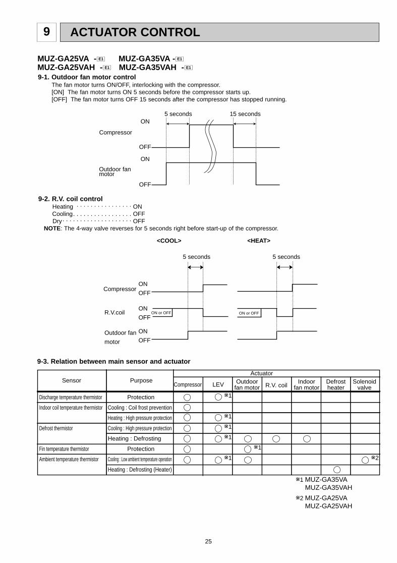
ACTUATOR CONTROL9
MUZ-GA25VA - MUZ-GA35VA -MUZ-GA25VAH - MUZ-GA35VAH - E1E1
E1E1
Discharge temperature thermistor
Indoor coil temperature thermistor
Defrost thermistor
Fin temperature thermistor
Ambient temperature thermistor
Purpose
Protection
Cooling : Coil frost prevention
Heating : High pressure protection
Cooling : High pressure protection
Heating : Defrosting
Protection
Cooling : Low ambient temperature operation
Heating : Defrosting (Heater)
Compressor LEV Outdoor fan motor
Indoor fan motor
Defrostheater
SolenoidvalveR.V. coil
SensorActuator
w1
w1
w1
w1
w1 w2
w1
w1 MUZ-GA35VA MUZ-GA35VAH
w2 MUZ-GA25VA MUZ-GA25VAH
9-3. Relation between main sensor and actuator
9-2. R.V. coil controlHeating . . . . . . . . . . . . . . . . ONCooling. . . . . . . . . . . . . . . . . OFFDry. . . . . . . . . . . . . . . . . . . . OFF
NOTE: The 4-way valve reverses for 5 seconds right before start-up of the compressor.
ON
OFF
ON
OFF
Outdoor fanmotor
Compressor
5 seconds 15 seconds
ON
OFFCompressor
Outdoor fan
motor
R.V.coilON
OFF
ON
OFF
<COOL>
5 seconds
<HEAT>
5 seconds
ON or OFF ON or OFF
9-1. Outdoor fan motor controlThe fan motor turns ON/OFF, interlocking with the compressor.[ON] The fan motor turns ON 5 seconds before the compressor starts up.[OFF] The fan motor turns OFF 15 seconds after the compressor has stopped running.
OB379 --1qxp 05.1.17 16:39 Page 25
26
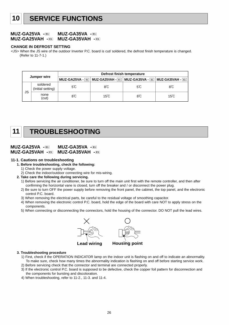
10 SERVICE FUNCTIONS
CHANGE IN DEFROST SETTING<JS> When the JS wire of the outdoor Inverter P.C. board is cut/ soldered, the defrost finish temperature is changed.
(Refer to 11-7-1.)
Jumper wireDefrost finish temperature
JSnone(cut)
soldered(Initial setting)
E1 MUZ-GA35VA -
8:
5:
MUZ-GA25VAH - E1 E1 MUZ-GA35VAH -MUZ-GA25VA - E1
15:
8:
8:
5:
15:
8:
MUZ-GA25VA - MUZ-GA35VA -MUZ-GA25VAH - MUZ-GA35VAH - E1E1
E1E1
11 TROUBLESHOOTING
3. Troubleshooting procedure1) First, check if the OPERATION INDICATOR lamp on the indoor unit is flashing on and off to indicate an abnormality.
To make sure, check how many times the abnormality indication is flashing on and off before starting service work.2) Before servicing check that the connector and terminal are connected properly.3) If the electronic control P.C. board is supposed to be defective, check the copper foil pattern for disconnection and
the components for bursting and discoloration.4) When troubleshooting, refer to 11-2., 11-3. and 11-4.
11-1. Cautions on troubleshooting1. Before troubleshooting, check the following:
1) Check the power supply voltage.2) Check the indoor/outdoor connecting wire for mis-wiring.
2. Take care the following during servicing.1) Before servicing the air conditioner, be sure to turn off the main unit first with the remote controller, and then after
confirming the horizontal vane is closed, turn off the breaker and / or disconnect the power plug.2) Be sure to turn OFF the power supply before removing the front panel, the cabinet, the top panel, and the electronic
control P.C. board.3) When removing the electrical parts, be careful to the residual voltage of smoothing capacitor. 4) When removing the electronic control P.C. board, hold the edge of the board with care NOT to apply stress on the
components.5) When connecting or disconnecting the connectors, hold the housing of the connector. DO NOT pull the lead wires.
Housing pointLead wiring
MUZ-GA25VA - MUZ-GA35VA -MUZ-GA25VAH - MUZ-GA35VAH - E1E1
E1E1
OB379 --1qxp 05.1.17 16:39 Page 26
27
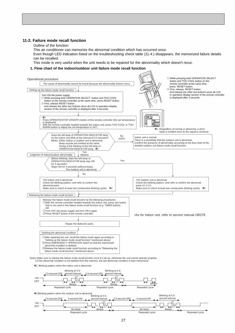
Outline of the functionThis air conditioner can memorize the abnormal condition which has occurred once.Even though LED indication listed on the troubleshooting check table (11-4.) disappears, the memorized failure detailscan be recalled.This mode is very useful when the unit needs to be repaired for the abnormality which doesn't recur.
11-2. Failure mode recall function
1. Flow chart of the indoor/outdoor unit failure mode recall function
Operational procedure
Yes(Blinks)
No(OFF)
Yes
No
Releasing the failure mode recall function
W1. Regardless of normal or abnormal, a short beep is emitted once as the signal is received.
Note1.Make sure to release the failure mode recall function once it's set up, otherwise the unit cannot operate properly. 2.If the abnormal condition is not deleted from the memory, the last abnormal condition is kept memorized.
W2. Blinking pattern when the indoor unit is abnormal:
W3.Blinking pattern when the outdoor unit is abnormal:
ONOFF
BeepsRepeated cycle Repeated cycle
ONOFF
No beep BeepsRepeated cycle
2.5-second OFFBlinking at 0.5-second interval
2.5-second OFF 3-second ONBlinking at 0.5-second interval
BeepsRepeated cycle
2.5-second OFFBlinking at 0.5-second interval
No beep BeepsRepeated cycle
2.5-second OFF 3-second ONBlinking at 0.5-second interval
Repeated cycle
Beeps
Does the left lamp of OPERATION INDICATOR lamp on the indoor unit blink at the interval of 0.5 seconds?Blinks: Either indoor or outdoor unit is abnormal. Beep sounds are emitted at the same timing of the blinking of the left lamp of OPERATION INDICATOR lamp. W2
The cause of abnormality cannot be found because the abnormality doesn't recur.
Setting up the failure mode recall function
Before blinking, does the left lamp of OPERATION INDICATOR lamp stay ON for 3 seconds?Stays ON for 3 seconds (without beep): The outdoor unit is abnormal.
The indoor unit is abnormal.Check the blinking pattern, and refer to confirm theabnormal point.Make sure to check at least two consecutive blinking cycles. W2
Turn ON the power supply.1 While pressing both OPERATION SELECT button and TOO COOL button on the remote controller at the same time, press RESET button.2 First, release RESET button. And release the other two buttons since all LCD in operation display section of the remote controller is displayed after 3 seconds.
Deleting the abnormal condition
1After repairing the unit, recall the failure mode again according to "Setting up the failure mode recall function" mentioned above.2Press EMERGENCY OPERATION switch so that the memorized abnormal condition is deleted.3Release the failure mode recall function according to "Releasing the failure mode recall function" mentioned above.
Repair the defective parts.
Release the failure mode recall function by the following procedures.1With the remote controller headed towards the indoor unit, press any button that is not used in this failure mode recall function (e.g. TIMER button) . OR1Turn OFF the power supply and turn ON it again.2Press RESET button of the remote controller.
Judgment of indoor/outdoor abnormality
W1Press OPERATE/STOP (ON/OFF) button of the remote controller (the set temperature is displayed).With the remote controller headed towards the indoor unit, press TOO COOL or TOOWARM button to adjust the set temperature to 24:.
The outdoor unit is abnormal.Check the blinking pattern, and refer to confirm the abnormalpoint (11-2.3.).Make sure to check at least two consecutive blinking cycles. W3
1 While pressing both OPERATION SELECT button and TOO COOL button on the
remote controller at the same time, press RESET button.2 First, release RESET button. And release the other two buttons since all LCD in operation display section of the remote controller is displayed after 3 seconds.
Indoor unit is normal. There is a possibility that the outdoor unit is abnormal.Confirm the presence of abnormality according to the flow chart of the detailed outdoor unit failure mode recall function.
•As for indoor unit, refer to service manual OB378.
OB379 --1qxp 05.1.17 16:39 Page 27
28
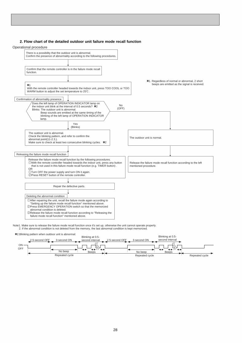
2. Flow chart of the detailed outdoor unit failure mode recall function
Operational procedure
Note1. Make sure to release the failure mode recall function once it's set up, otherwise the unit cannot operate properly. 2. If the abnormal condition is not deleted from the memory, the last abnormal condition is kept memorized.
W2.Blinking pattern when outdoor unit is abnormal:
Yes(Blinks)
No(OFF)
ONOFF
No beep BeepsRepeated cycle
2.5-second OFF 3-second ONBlinking at 0.5-second interval
No beep BeepsRepeated cycle
2.5-second OFF 3-second ONBlinking at 0.5-second interval
Repeated cycle
W1. Regardless of normal or abnormal, 2 short beeps are emitted as the signal is received.
Does the left lamp of OPERATION INDICATOR lamp onthe indoor unit blink at the interval of 0.5 seconds? W2Blinks: The outdoor unit is abnormal.
Beep sounds are emitted at the same timing of theblinking of the left lamp of OPERATION INDICATOR
lamp.
Deleting the abnormal condition
1After repairing the unit, recall the failure mode again according to "Setting up the failure mode recall function" mentioned above.2Press EMERGENCY OPERATION switch so that the memorized abnormal condition is deleted.3Release the failure mode recall function according to "Releasing the failure mode recall function" mentioned above.
Repair the defective parts.
Confirmation of abnormality presence
W1With the remote controller headed towards the indoor unit, press TOO COOL or TOOWARM button to adjust the set temperature to 25:.
The outdoor unit is normal.
Releasing the failure mode recall function
Release the failure mode recall function by the following procedures.1With the remote controller headed towards the indoor unit, press any button that is not used in this failure mode recall function (e.g. TIMER button) .OR1Turn OFF the power supply and turn ON it again.2Press RESET button of the remote controller.
The outdoor unit is abnormal.Check the blinking pattern, and refer to confirm theabnormal point(11-2.3.).Make sure to check at least two consecutive blinking cycles. W2
Release the failure mode recall function according to the left mentioned procedure.
Confirm that the remote controller is in the failure mode recallfunction.
There is a possibility that the outdoor unit is abnormal.Confirm the presence of abnormality according to the following procedures.
OB379 --1qxp 05.1.17 16:39 Page 28
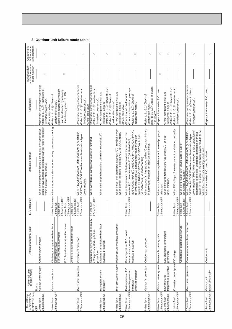
29
3. Outdoor unit failure mode tableO
FF
2-tim
e fla
sh2.
5 se
cond
s O
FF
3-tim
e fla
sh2.
5 se
cond
s O
FF
4-tim
e fla
sh2.
5 se
cond
s O
FF
5-tim
e fla
sh2.
5 se
cond
s O
FF
6-tim
e fla
sh2.
5 se
cond
s O
FF
7-tim
e fla
sh2.
5 se
cond
s O
FF
8-tim
e fla
sh2.
5 se
cond
s O
FF
9-tim
e fla
sh2.
5 se
cond
s O
FF
10-t
ime
flash
2.5
seco
nds
OF
F
11-t
ime
flash
2.5
seco
nds
OF
F
12-t
ime
flash
2.5
seco
nds
OF
F
14-t
ime
flash
2.5
seco
nds
OF
F N
orm
alO
utdo
or p
ower
sys
tem
Out
door
ther
mis
tors
Ove
rcur
rent
pro
tect
ion
Ref
riger
ant s
yste
m
prot
ectio
n
Hig
h pr
essu
re p
rote
ctio
n
Fin
tem
pera
ture
/ P.C
. bo
ard
tem
pera
ture
ther
mis
tor
over
heat
pro
tect
ion
Out
door
fan
prot
ectio
n
Out
door
con
trol
sys
tem
Low
dis
char
ge
tem
pera
ture
pro
tect
ion
Con
vert
er c
ontr
ol s
yste
m
Ove
rcur
rent
pro
tect
ion
Out
door
uni
t(O
ther
abn
orm
ality
)
Out
door
pow
er s
yste
m
Dis
char
ge te
mpe
ratu
re th
erm
isto
r D
efro
st th
erm
isto
r F
in te
mpe
ratu
re th
erm
isto
r
P.C
. boa
rd te
mpe
ratu
re th
erm
isto
r
Am
bien
t tem
pera
ture
ther
mis
tor
Ove
rcur
rent
pro
tect
ion
Com
pres
sor
sync
hron
ous
abno
rmal
ity(
Com
pres
sor
star
t-up
failu
re
prot
ectio
n)D
isch
arge
tem
pera
ture
ther
mis
tor
over
heat
pro
tect
ion
Hig
h pr
essu
re o
verh
eat p
rote
ctio
n
Fin
tem
pera
ture
/ P.C
. boa
rdte
mpe
ratu
re th
erm
isto
rov
erhe
at p
rote
ctio
n
Out
door
fan
prot
ectio
n
Non
vola
tile
mem
ory
data
Low
dis
char
ge te
mpe
ratu
re
prot
ectio
n
DC
vol
tage
Com
pres
sor
each
pha
se c
urre
nt
Com
pres
sor
open
-pha
se p
rote
ctio
n
Out
door
uni
t
1-tim
e fla
sh e
very
2.5
seco
nds
3-tim
e fla
sh2.
5 se
cond
s O
FF
4-tim
e fla
sh2.
5 se
cond
s O
FF
2-tim
e fla
sh2.
5 se
cond
s O
FF
11-t
ime
flash
2.5
seco
nds
OF
F
12-t
ime
flash
2.5
seco
nds
OF
F
7-tim
e fla
sh
2.5
seco
nds
OF
F
5-tim
e fla
sh2.
5 se
cond
s O
FF
8-tim
e fla
sh2.
5 se
cond
s O
FF
9-tim
e fla
sh2.
5 se
cond
s O
FF
10-t
ime
flash
2.5
seco
nds
OF
F
W
hen
it co
nsec
utiv
ely
occu
rs 3
tim
es th
at th
e co
mpr
esso
r st
ops
for
over
curr
ent p
rote
ctio
n or
sta
rt-u
p fa
ilure
pro
tect
ion
with
in 1
min
ute
afte
r st
art-
up.
Whe
n th
erm
isto
rs s
hort
or
open
dur
ing
com
pres
sor
runn
ing.
Whe
n 14
A(M
UZ
-GA
25V
A, M
UZ
-GA
25V
AH
)/ 2
4A(M
UZ
-G
A35
VA
, MU
Z-G
A35
VA
H)
curr
ent f
low
into
inte
llige
nt
pow
er m
odul
e.
Whe
n w
avef
orm
of c
ompr
esso
r cu
rren
t is
dist
orte
d.
Whe
n di
scha
rge
tem
pera
ture
ther
mis
tor
exce
eds1
16:
.
Whe
n in
door
coi
l the
rmis
tor
exce
eds
70:
in H
EA
T m
ode.
Whe
n de
fros
t the
rmis
tor
exce
eds
70:
in C
OO
L m
ode.
Whe
n te
mpe
ratu
re o
f fin
tem
pera
ture
ther
mis
tor
on th
ein
vert
er P
.C. b
oard
exc
eeds
82 :
(MU
Z-G
A25
VA
, M
UZ
-GA
25V
AH
)/ 8
3:(M
UZ
-GA
35V
A, M
UZ
-GA
35V
AH
),or
tem
pera
ture
of P
.C. b
oard
tem
pera
ture
ther
mis
tor
exce
eds
81 :
(MU
Z-G
A25
VA
, MU
Z-G
A25
VA
H)/
85:
(MU
Z-G
A35
VA
, MU
Z-G
A35
VA
H).
W
hen
outd
oor
fan
has
stop
ped
with
in 3
0 se
cond
s 3-
times
in a
row
afte
r ou
tdoo
r fa
n st
art-
up, u
nit s
tops
.
Whe
n no
nvol
atile
mem
ory
data
can
not b
e re
ad p
rope
rly,
unit
stop
s.W
hen
disc
harg
e te
mpe
ratu
re h
as b
een
50:
or
less
fo
r 20
min
utes
.
Whe
n D
C v
olta
ge o
f inv
erte
r ca
nnot
be
dete
cted
nor
mal
ly.
Whe
n co
mpr
esso
r ea
ch p
hase
cur
rent
can
not
be
dete
cted
nor
mal
ly.
Whe
n 14
A(M
UZ
-GA
25V
A, M
UZ
-GA
25V
AH
)/ 2
4A(M
UZ
-G
A35
VA
, MU
Z-G
A35
VA
H)
curr
ent f
low
into
inte
llige
nt
pow
er m
odul
e (I
PM
). W
hen
the
open
-pha
se o
pera
tion
of
com
pres
sor
is d
etec
ted.
Whe
n th
e in
terp
hase
sho
rt o
ut
occu
rs in
the
outp
ut o
f the
inte
llige
nt p
ower
mod
ule
(IP
M).
Whe
n th
e co
mpr
esso
r w
indi
ng s
hort
s ou
t.W
hen
the
inve
rter
P.C
. boa
rd is
failu
re.
•R
econ
nect
com
pres
sor
conn
ecto
r.•R
efer
to 1
1-6.A
"How
to c
heck
i
nver
ter/
com
pres
sor"
.•C
heck
sto
p va
lve.
•Ref
er to
11-
6.G
"Che
ck o
f o
utdo
or th
erm
isto
rs".
❈D
efec
tive
outd
oor
ther
mis
tors
can
be id
entif
ied
by c
heck
ing
th
e bl
inki
ng p
atte
rn o
f LE
D.
•Rec
onne
ct c
ompr
esso
r co
nnec
tor.
•Ref
er to
11-
6.A
"How
to c
heck
i
nver
ter/
com
pres
sor"
.•C
heck
sto
p va
lve.
•Rec
onne
ct c
ompr
esso
r co
nnec
tor.
•Ref
er to
11-
6.A
"How
to c
heck
i
nver
ter/
com
pres
sor"
.•C
heck
ref
riger
ant c
ircui
t and
ref
riger
ant a
mou
nt.
•Ref
er to
11-
6.L
"Che
ck o
f LE
V".
•Ref
er to
11-
6.G
"Che
ck o
f o
utdo
or th
erm
isto
rs".
•Che
ck r
efrig
eran
t circ
uit a
nd r
efrig
eran
t am
ount
.•C
heck
sto
p va
lve.
•Che
ck a
roun
d ou
tdoo
r un
it.•C
heck
out
door
uni
t air
pass
age.
•Ref
er to
11-
6.I
"Che
ck o
f o
utdo
or fa
n m
otor
".
•Ref
er to
11-
6.I
"Che
ck o
f o
utdo
or fa
n m
otor
.R
efer
to 1
1-6.N
"Che
ck o
f inv
erte
r P
.C. b
oard
".•R
epla
ce th
e in
vert
er P
.C. b
oard
.
•Che
ck r
efrig
eran
t circ
uit a
nd r
efrig
eran
t am
ount
.•R
efer
to 1
1-6.L
"Che
ck o
f LE
V".
•Ref
er to
11-
6.A
"How
to c
heck
i
nver
ter/
com
pres
sor"
.
•Rec
onne
ct c
ompr
esso
r co
nnec
tor.
•Ref
er to
11-
6. A
"How
to c
heck
i
nver
ter/
com
pres
sor"
.
•Rep
lace
the
inve
rter
P.C
. boa
rd.
The
left
lam
p of
OP
ER
ATI
ON
IN
DIC
ATO
R la
mp
Abn
orm
al p
oint
(Fai
lure
mod
e)D
etai
ls o
f abn
orm
al p
oint
Det
ectio
n m
etho
dC
heck
poi
ntIn
door
/out
door
unit
failu
re m
ode
reca
ll fu
nctio
n
Out
door
uni
tfa
ilure
mod
ere
call
func
tion
LED
indi
catio
n
OB379 --1qxp 05.1.17 16:39 Page 29
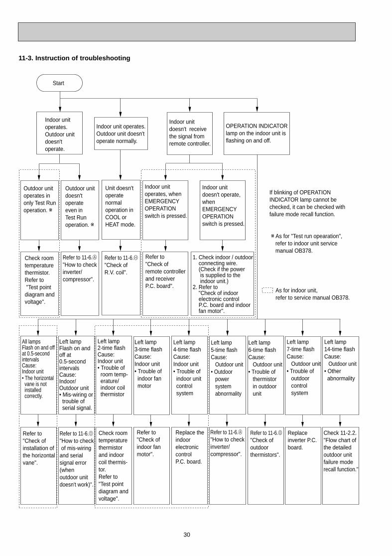
30
Start
Indoor unit operates.Outdoor unit doesn't operate.
Indoor unit doesn't receive the signal from remote controller.
OPERATION INDICATORlamp on the indoor unit is flashing on and off.
Outdoor unit operates in only Test Run operation. w
Outdoor unit doesn't operate even in Test Run operation. w
Indoor unit operates, when EMERGENCY OPERATION switch is pressed.
Indoor unit doesn't operate, when EMERGENCY OPERATION switch is pressed.
Check room temperature thermistor.Refer to "Test point diagram and voltage".
Refer to 11-6.A"How to check inverter/compressor".
Refer to "Check of remote controller and receiver P.C. board".
1. Check indoor / outdoor connecting wire. (Check if the power is supplied to the indoor unit.)2. Refer to "Check of indoor electronic control P.C. board and indoor fan motor".
Unit doesn't operate normaloperation in COOL or HEAT mode.
Refer to 11-6.H "Check of R.V. coil".
Left lampFlash on and off at 0.5-secondintervalsCause: Indoor/Outdoor unit• Mis-wiring or trouble of serial signal.
Left lamp2-time flash Cause:Indoor unit• Trouble of room temp- erature/ indoor coil thermistor
Left lamp3-time flash Cause:Indoor unit• Trouble of indoor fan motor
Left lamp5-time flash Cause: Outdoor unit• Outdoor power system abnormality
Left lamp6-time flash Cause: Outdoor unit• Trouble of thermistor in outdoor unit
Left lamp7-time flash Cause: Outdoor unit• Trouble of outdoor control system
Refer to 11-6.o
"How to check of mis-wiringand serial signal error (when outdoor unit doesn't work)".
All lamps Flash on and off at 0.5-second intervals Cause:Indoor unit• The horizontal vane is not installed correctly.
Refer to"Check of installation of the horizontalvane".
Check room temperature thermistor and indoor coil thermis-tor.Refer to "Test point diagram and voltage".
Refer to "Check of indoor fan motor".
Refer to 11-6.A "How to checkinverter/ compressor".
Refer to 11-6.G "Check of outdoor thermistors".
Replace inverter P.C. board.
Left lamp14-time flash Cause: Outdoor unit• Other abnormality
Check 11-2.2."Flow chart of the detailed outdoor unit failure mode recall function."
Left lamp4-time flash Cause:Indoor unit• Trouble of indoor unit control system
Replace the indoor electronic control P.C. board.
As for indoor unit,refer to service manual OB378.
Indoor unit operates.Outdoor unit doesn'toperate normally.
If blinking of OPERATION INDICATOR lamp cannot bechecked, it can be checked with failure mode recall function.
w As for "Test run opearation", refer to indoor unit service manual OB378.
11-3. Instruction of troubleshooting
OB379 --1qxp 05.1.17 16:39 Page 30

31
ON
OFF2.5-second OFF 2.5-second OFF
NOTE 1. The location of LED is illustrated at the right figure. Refer to 11-7.1.2. LED lights up during normal operation.
The flashing frequency shows the number of times the LED blinks after every 2.5-second OFF.(Example) When the flashing frequency is “2”.
Abnormal point/ ConditionWhen it consecutively occurs 3times that the compressor stops for overcurrent protection or start-up failure protection within 1minute start-up.
When discharge temperature thermistor, fin temperature thermistor, defrost thermistor, P.C. board temperature thermistor or ambient temperature thermistor shorts or opens during compressor running, compressor stops.When nonvolatile memory data cannot be read properly, compressor stops.
(When the left lamp of OPERATION INDICATOR lamp of indoor unit lights up or flashes 7-time.)
When 14A(MUZ-GA25VA, MUZ-GA25VAH)/ 24A(MUZ-GA35VA, MUZ-GA35VAH) current flows into intelligent power module, compressor stops and restarts 3 minutes later.
When discharge temperature thermistor exceeds 116:, compressor stops. Compressor can restart if discharge temperature thermistor reads 100: or less 3 minutes later.
When temperature of fin temperature thermistor on the heat sink exceeds 82:(MUZ-GA25VA, MUZ-GA25VAH)/ 83:(MUZ-GA35VA, MUZ-GA35VAH) or temperature of P.C. board temperature thermistor exceeds 81:(MUZ-GA25VA, MUZ-GA25VAH)/ 85:(MUZ-GA35VA, MUZ-GA35VAH), compressor stops and restarts 3 minutes later.When indoor coil thermistor exceeds 70: in HEAT mode. When the defrost thermistor exceeds 70: in COOL mode.
When current from power outlet exceeds 5.2A(MUZ-GA25VA, MUZ-GA25VAH)/ 6.1A(MUZ-GA35VA, MUZ-GA35VAH), compressor frequency lowers.
When indoor coil thermistor exceeds 55: in HEAT mode, compressor frequency lowers.
When indoor coil thermistor reads 8: or less in COOL mode, compressor frequency lowers.
When discharge temperature thermistor exceeds 111:,compressor frequency lowers.
When discharge temperature has been 50: or less for 20 minutes.
No.
1
2
3
6
7
8
9
14
15
16
17
18
Symptom LED indication Detection method Check point
Outdoor unit does not operate
'Outdoor unit stops and restarts 3 minutes later' is repeated
Outdoor unit operates
Outdoor unit operates
1-time flash every 2.5 seconds
NOTE: For abnormality location, refer to 'Indoor troubleshooting check table'. Refer to service manual OB371.
2-time flash 2.5 seconds OFF
3-time flash2.5 seconds OFF
4-time flash2.5 seconds OFF
5-time flash2.5 seconds OFF
1-time flash2.5 seconds OFF
3-time flash 2.5 seconds OFF
4-time flash2.5 seconds OFF
7-time flash2.5 seconds OFF
Outdoor power system
Outdoor thermistors
Outdoor control system
Overcurrent protection
Discharge temperature overheatprotection
Fin temperature /P.C. board temperature thermistor overheat protection
High pressure protection
Frequency drop by current protection
Frequency drop by high pressure protection Frequency drop by defrosting in COOL mode
Frequency drop by discharge temperature protection
Low discharge temperature protection
· Check stop valve.· Reconnect connector of compressor.· Refer to 11-6.A "How to check
inverter/ compressor".· Refer to 11-6.C "Check of intelligent
power module".
· Refer to 11-6.G "Check of outdoor thermistors".
· Check stop valve.· Reconnect connector of compressor.· Refer to 11-6.A "How to check inverter/compressor".· Refer to 11-6.C "Check of intelligent power module".
Replace inverter P.C. board.
· Check refrigerant circuit and refrigerant amount.
· Refer to 11-6.L "Check of LEV".
· Check around outdoor unit.· Check outdoor unit air passage.· Refer to 11-6.I "Check of outdoor
fan motor".
· Check refrigerant circuit and refrigerant amount.
· Check stop valve.
The unit is normal, but check the following.· Check if indoor filters are clogged. · Check if refrigerant is short.· Check if indoor/outdoor unit air
circulation is short cycled.
· Refer to 11-6.L "Check of LEV".· Check refrigerant circuit and
refrigerant amount.
Inverter P.C. board (Parts side)
LEDFlashing
Refer to 11-6.O "How to check mis-wiring and serial signal error.
When the communication failure between the indoor and outdoor unit for 3 minutes.
serial signal
8-time flash2.5 seconds OFF
Compressor synchronous abnormality
When the waveform of compressor current is distorted. · Reconnect connector of compressor.· Refer to 11-6.A "How to check inverter/compressor".· Refer to 11-6.C "Check of intelligent power module".
8-time flash2.5 seconds OFF
PAM protection
PAM:Pulse Amplitude Modulation
When the overcurrent flows into IGBT(Insulated Gate Bipolar transistor : TR821) or when the bus-bar voltage reaches 320V or more, PAM stops and restarts.
This is not malfunction.PAM protection will be activated inthe following cases;1Instantaneous power voltage drop (Short time power failure)2When the power supply voltage is high.
9-time flash2.5 seconds OFF
Inverter check mode
When the connector of compressor is disconnected, inverter check mode starts.
Check if the connector of thecompressor is correctly connected.Refer to 11-6.A "How to checkinverter/ compressor".
4
10
19
10-time flash2.5 seconds OFF
Outdoor fan
6-time flash2.5 seconds OFF
When outdoor fan has stopped within 30 seconds 3-times a row after outdoor fan start-up, unit stops.
· Refer to 11-6.I "Check of outdoor fan motor.
· Refer to 11-6.N "Check of inverter P.C. board.
11
12
13
12-time flash2.5 seconds OFF
Compressor each phase current
When compressor each phase current cannot be detected normally
· Refer to 11-6.A "How to check inverter/compresssor".
13-time flash2.5 seconds OFF
DC voltage When DC voltage of inverter cannot be detected normally. · Check for short time power failure by such as lightning strike.
· Refer to 11-6.A "How to check inverter/compresssor".
· Check refrigerant circuit and refrigerant amount.
· Refer to 11-6.L "Check of LEV".
· Refer to 11-6.G "Check of outdoor thermistors".
Refer to 11-2.2. Flow chart of the detailed outdoor unit failure mode recall function.
When outdoor unit is failure. Outdoor unit (Other abnormality)5
14-time flash2.5 seconds OFF
0.5-second ON 0.5-second ON
11-4. Troubleshooting check table
OB379 --2qxp 05.1.17 16:38 Page 31
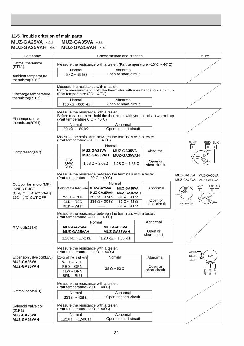
32
11-5. Trouble criterion of main parts
Part name FigureCheck method and criterion
Outdoor fan motor(MF)INNER FUSE (Only MUZ-GA25VA/H)152i : CUT OFF0
5
R.V. coil(21S4)
Expansion valve coil(LEV)MUZ-GA35VAMUZ-GA35VAH
Measure the resistance between the terminals with a tester.(Part temperature –20˚C ~ 40˚C)
WHT – BLKBLK – REDRED – WHT
Abnormal
Open orshort-circuit
Normal
Measure the resistance between the terminals with a tester.(Part temperature –20˚C ~ 40˚C)
Normal
1.26 k" ~ 1.62 k" 1.20 k" ~ 1.55 k"
WHT – REDRED – ORNYLW – BRNBRN – BLU
Abnormal
Open orshort-circuit
Abnormal
Open orshort-circuit
Normal
38 " ~ 50 "
Measure the resistance with a tester.(Part temperature : –20˚C ~ 40˚C)
Measure the resistance with a tester. (Part temperature –10˚C ~ 40˚C)
Color of the lead wire
Color of the lead wire
Discharge temperaturethermistor(RT62)
Measure the resistance with a tester. Before measurement, hold the thermistor with your hands to warm it up.(Part temperature 0˚C ~ 40˚C)
Normal150 k" ~ 600 k"
30 k" ~ 180 k"
AbnormalOpen or short-circuit
Normal5 k" ~ 55 k"
AbnormalOpen or short-circuit
Defrost thermistor(RT61)
Fin temperaturethermistor(RT64)
Measure the resistance with a tester. Before measurement, hold the thermistor with your hands to warm it up.(Part temperature 0˚C ~ 40˚C)
Normal AbnormalOpen or short-circuit
Ambient temperaturethermistor(RT65)
292 " ~ 374 "236 " ~ 304 "
31 " ~ 41 "31 " ~ 41 "31 " ~ 41 "
Measure the resistance between the terminals with a tester. (Part temperature –20˚C ~ 40˚C)
Compressor(MC)
Defrost heater(H)
Measure the resistance with a tester. (Part temperature -20˚C ~ 40˚C)
Normal333 " ~ 428 "
AbnormalOpen or short-circuit
Normal1,220 " ~ 1,580 "
AbnormalOpen or short-circuit
Measure the resistance with a tester. (Part temperature -20˚C ~ 40˚C)
MUZ-GA25VAMUZ-GA25VAH
U-VU-WV-W
Abnormal
Open orshort-circuit
Normal
1.28 " ~ 1.66 "1.58 " ~ 2.03"
MUZ-GA35VAMUZ-GA35VAH
MUZ-GA25VAMUZ-GA25VAH
MUZ-GA35VAMUZ-GA35VAH
MUZ-GA25VAMUZ-GA25VAH
MUZ-GA35VAMUZ-GA35VAH
MUZ-GA25VAMUZ-GA25VAH
2 3
W
UV
1
WHT RED BLK
2 3
W
UV
1
WHT RED BLK
WHTREDBLK
FUSE
Solenoid valve coil(21R1)MUZ-GA25VAMUZ-GA25VAH
MUZ-GA35VAMUZ-GA35VAH
LEV
WHT6
RED1
ORN4
YLW
5
BR
N2
BLU
3
MUZ-GA25VA - MUZ-GA35VA -MUZ-GA25VAH - MUZ-GA35VAH - E1E1
E1E1
OB379 --2qxp 05.1.17 16:38 Page 32
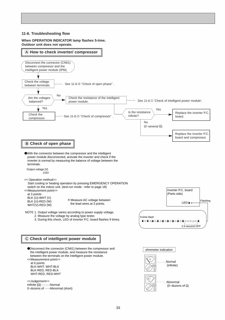
33
●With the connector between the compressor and the intelligent power module disconnected, activate the inverter and check if the inverter is normal by measuring the balance of voltage between the terminals.
<< Operation method>> Start cooling or heating operation by pressing EMERGENCY OPERATION
switch on the indoor unit. (test-run mode : refer to page 18)<<Measurement point>>
at 3 pointsBLK (U)-WHT (V)BLK (U)-RED (W) WHT(V)-RED (W)
NOTE 1. Output voltage varies according to power supply voltage. 2. Measure the voltage by analog type tester. 3. During this check, LED of inverter P.C. board flashes 9 times.
●Disconnect the connector (CN61) between the compressor and the intelligent power module, and measure the resistance between the terminals on the intelligent power module.
<<Measurement point>> at 6 points BLK-WHT, WHT-BLK BLK-RED, RED-BLK WHT-RED, RED-WHT <<Judgement>>Infinite ["]···········Normal 0~dozens of ······Abnormal (short)
Output voltage [V] 115V
w Measure AC voltage between the lead wires at 3 points.
ohmmeter indication
Normal (infinite)
Abnormal (0~dozens of ")X1
"
X1
"
LED
Inverter P.C. board(Parts side)
9-time flash
2.5-second OFF
Flashing
Check of open phaseB
Check of intelligent power moduleC
How to check inverter/ compressorA
When OPERATION INDICATOR lamp flashes 5-time.Outdoor unit does not operate.
Check the voltagebetween terminals.
Check thecompressor.
Disconnect the connector (CN61)between compressor and the intelligent power module (IPM).
Check the resistance of the intelligentpower module.
See 11-6.D “Check of compressor” .
No
See 11-6.B “Check of open phase” .
See 11-6.C 'Check of intelligent power module'.
Is the resistanceinfinite?
YesReplace the inverter P.C.board.
No (0~several ")
Yes
Are the voltagesbalanced?
Replace the inverter P.C.board and compressor.
11-6. Troubleshooting flow
OB379 --2qxp 05.1.17 16:38 Page 33
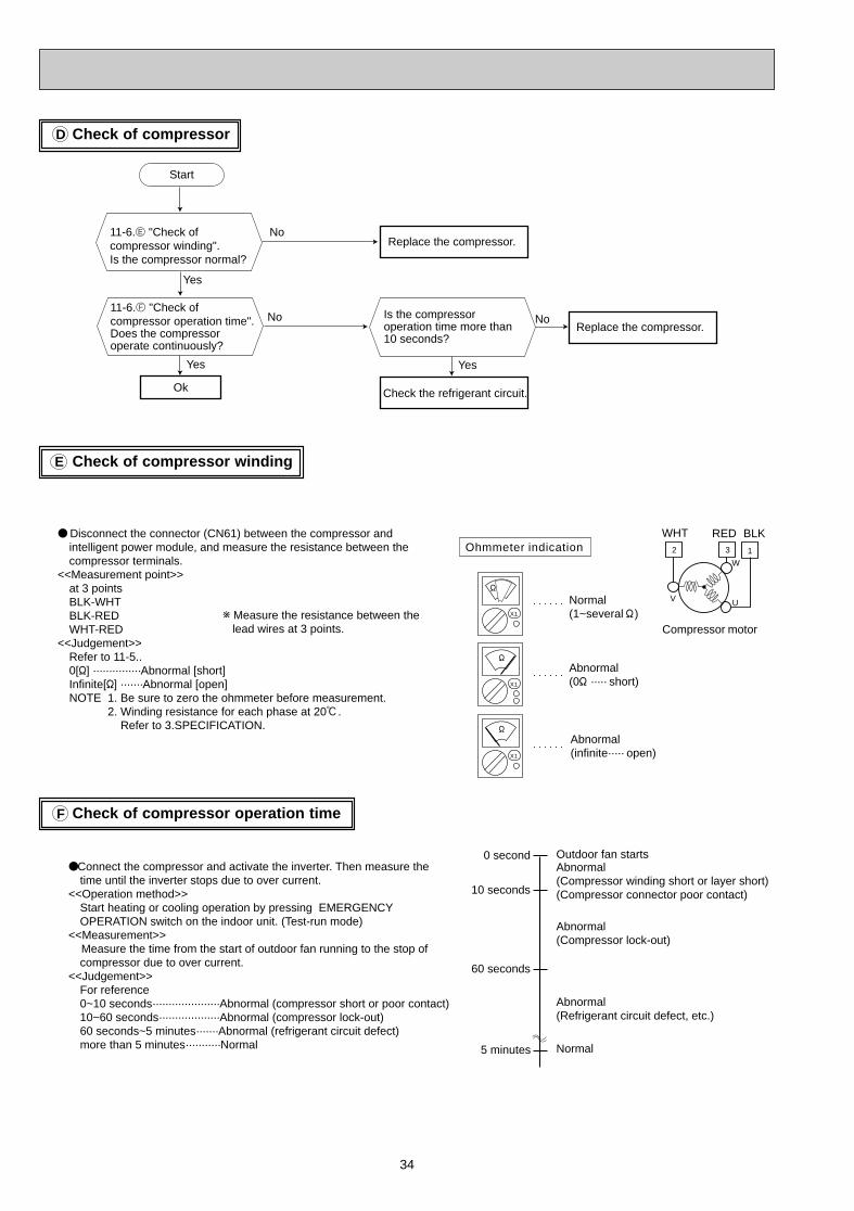
34
Check of compressorD
Check of compressor windingE
Check of compressor operation timeF
● Disconnect the connector (CN61) between the compressor and intelligent power module, and measure the resistance between the compressor terminals.
<<Measurement point>>at 3 points BLK-WHTBLK-REDWHT-RED
<<Judgement>>Refer to 11-5..0["] ···············Abnormal [short]Infinite["] ·······Abnormal [open]NOTE 1. Be sure to zero the ohmmeter before measurement. 2. Winding resistance for each phase at 20:. Refer to 3.SPECIFICATION.
●Connect the compressor and activate the inverter. Then measure the time until the inverter stops due to over current.
<<Operation method>>Start heating or cooling operation by pressing EMERGENCY OPERATION switch on the indoor unit. (Test-run mode)
<<Measurement>> Measure the time from the start of outdoor fan running to the stop of
compressor due to over current.<<Judgement>>
For reference0~10 seconds·····················Abnormal (compressor short or poor contact)10~60 seconds···················Abnormal (compressor lock-out)60 seconds~5 minutes·······Abnormal (refrigerant circuit defect)more than 5 minutes···········Normal
w Measure the resistance between the lead wires at 3 points.
Outdoor fan startsAbnormal (Compressor winding short or layer short)(Compressor connector poor contact)
Abnormal(Compressor lock-out)
Abnormal(Refrigerant circuit defect, etc.)
Normal
0 second
10 seconds
60 seconds
5 minutes
Normal(1~several " )
Abnormal(0" ····· short)
Abnormal(infinite····· open)
Ohmmeter indication
Start
Ok
Replace the compressor.11-6.E "Check of compressor winding".Is the compressor normal?
No
Replace the compressor.No
Yes
X1
"
X1
"
X1
"
2 3
W
UV
1
WHT
Compressor motor
RED BLK
Yes
11-6.F "Check of compressor operation time". Does the compressor operate continuously?
Is the compressor operation time more than 10 seconds?
No
Check the refrigerant circuit.
Yes
OB379 --2qxp 05.1.17 16:38 Page 34
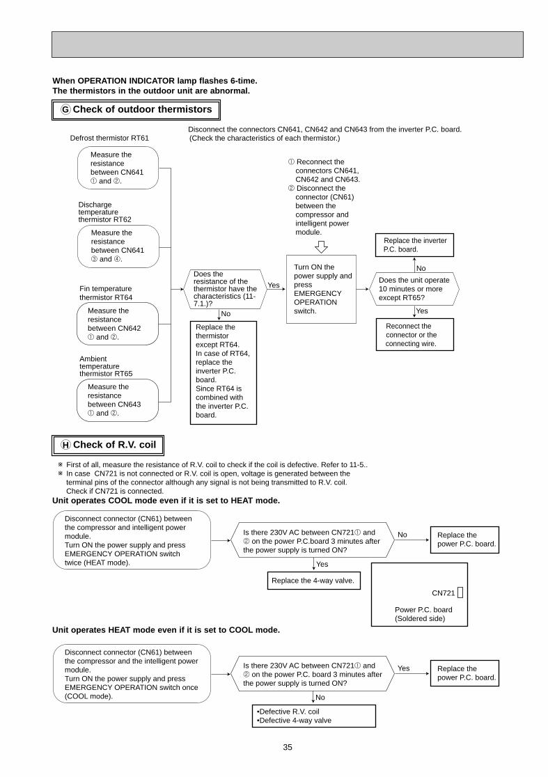
35
Check of outdoor thermistorsG
When OPERATION INDICATOR lamp flashes 6-time.The thermistors in the outdoor unit are abnormal.
Measure the resistance between CN641 1 and 2.
Measure the resistance between CN642 1 and 2.
No
Yes
Replace the thermistor except RT64.In case of RT64, replace the inverter P.C. board.Since RT64 is combined with the inverter P.C. board.
Replace the inverter P.C. board.
Disconnect the connectors CN641, CN642 and CN643 from the inverter P.C. board.(Check the characteristics of each thermistor.)
1 Reconnect the connectors CN641, CN642 and CN643.
2 Disconnect the connector (CN61) between the compressor and intelligent power module.
Defrost thermistor RT61
Measure the resistance between CN641 3 and 4.
Turn ON the power supply and press EMERGENCY OPERATION switch.
Discharge temperature thermistor RT62
Fin temperature thermistor RT64
Does the resistance of the thermistor have the characteristics (11-7.1.)?
No
Yes
Does the unit operate 10 minutes or more except RT65?
Reconnect the connector or the
connecting wire.
Measure the resistance between CN643 1 and 2.
Ambient temperature thermistor RT65
Check of R.V . coilH
Disconnect connector (CN61) between the compressor and intelligent power module.Turn ON the power supply and press EMERGENCY OPERATION switch twice (HEAT mode).
Is there 230V AC between CN7211 and 2 on the power P.C.board 3 minutes after the power supply is turned ON?
Yes
No Replace the power P.C. board.
Replace the 4-way valve.
Disconnect connector (CN61) between the compressor and the intelligent power module.Turn ON the power supply and press EMERGENCY OPERATION switch once (COOL mode).
Is there 230V AC between CN7211 and 2 on the power P.C. board 3 minutes after the power supply is turned ON?
No
Yes Replace the power P.C. board.
•Defective R.V. coil•Defective 4-way valve
w First of all, measure the resistance of R.V. coil to check if the coil is defective. Refer to 11-5..w In case CN721 is not connected or R.V. coil is open, voltage is generated between the terminal pins of the connector although any signal is not being transmitted to R.V. coil. Check if CN721 is connected.
CN721
Power P.C. board(Soldered side)
Unit operates COOL mode even if it is set to HEA T mode.
Unit operates HEA T mode even if it is set to COOL mode.
OB379 --2qxp 05.1.17 16:38 Page 35
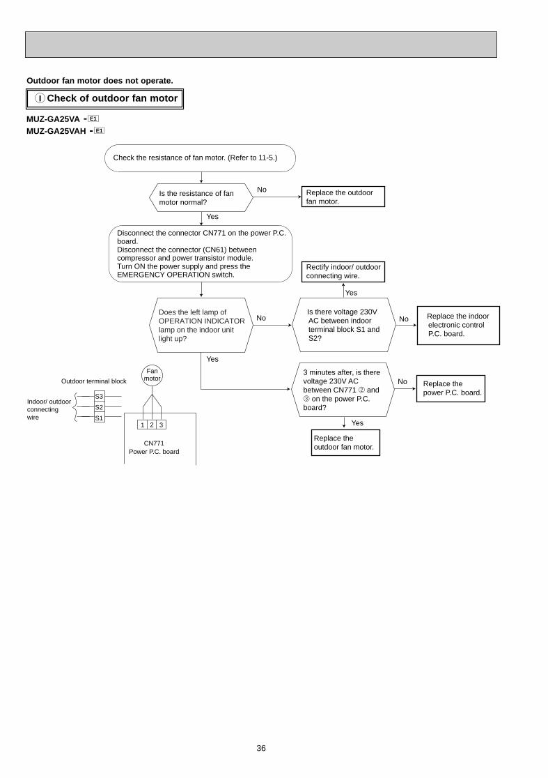
36
Check of outdoor fan motorI
Outdoor fan motor does not operate.
Is there voltage 230V AC between indoor terminal block S1 and S2?
Replace the outdoor fan motor.
Does the left lamp of OPERATION INDICATOR lamp on the indoor unit light up?
Is the resistance of fan motor normal?
3 minutes after, is there voltage 230V AC between CN771 2 and 3 on the power P.C. board?
Disconnect the connector CN771 on the power P.C. board.Disconnect the connector (CN61) between compressor and power transistor module.Turn ON the power supply and press the EMERGENCY OPERATION switch.
Yes
Yes
Yes
No
No
CN771Power P.C. board
1 2 3
FanmotorOutdoor terminal block
S3
S2
S1
Check the resistance of fan motor. (Refer to 11-5.)
Replace the power P.C. board.
Rectify indoor/ outdoor connecting wire.
No
Replace the indoor electronic control P.C. board.
Replace the outdoorfan motor.
No
Yes
Indoor/ outdoorconnectingwire
MUZ-GA25VA -MUZ-GA25VAH - E1
E1
OB379 --2qxp 05.1.17 16:38 Page 36
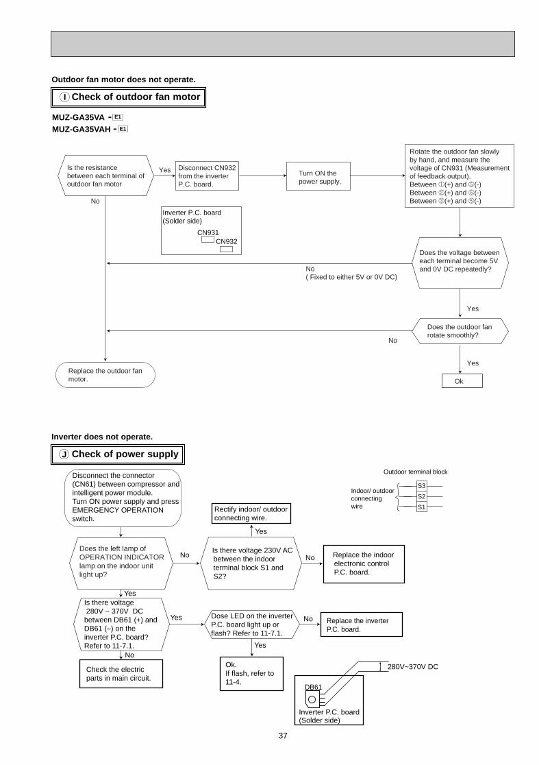
37
Check of power supplyJ
Inverter does not operate.
Check of outdoor fan motorI
Outdoor fan motor does not operate.
Does the voltage betweeneach terminal become 5Vand 0V DC repeatedly?
Does the outdoor fanrotate smoothly?
Ok
No
Yes
Yes
No( Fixed to either 5V or 0V DC)
Yes
No
Rotate the outdoor fan slowlyby hand, and measure thevoltage of CN931 (Measurementof feedback output).Between 1(+) and 5(-)Between 2(+) and 5(-)Between 3(+) and 5(-)
Is the resistancebetween each terminal ofoutdoor fan motor
Disconnect CN932from the inverter P.C. board.
Replace the outdoor fanmotor.
CN931CN932
Inverter P.C. board(Solder side)
Turn ON the power supply.
Disconnect the connector(CN61) between compressor and intelligent power module.Turn ON power supply and press EMERGENCY OPERATION switch.
Check the electric parts in main circuit.
Ok.If flash, refer to 11-4.
Is there voltage 280V ~ 370V DC between DB61 (+) and DB61 (–) on the inverter P.C. board?Refer to 11-7.1.
Dose LED on the inverter P.C. board light up or flash? Refer to 11-7.1.
Outdoor terminal block
S3
S2
S1
Yes
Yes
Yes
No
No
Replace the indoor electronic control P.C. board.
No
Yes
No
Indoor/ outdoorconnectingwire
Replace the inverter P.C. board.
DB61
280V~370V DC
Inverter P.C. board(Solder side)
Is there voltage 230V AC between the indoor terminal block S1 and S2?
Rectify indoor/ outdoor connecting wire.
Does the left lamp of OPERATION INDICATOR lamp on the indoor unit light up?
MUZ-GA35VA -MUZ-GA35VAH - E1
E1
OB379 --2qxp 05.1.17 16:38 Page 37
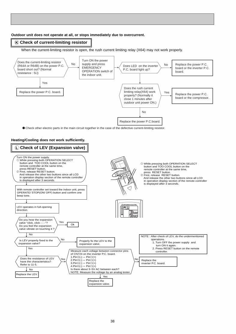
38
Outdoor unit does not operate at all, or stops immediately due to overcurrent.
Check of LEV (Expansion valve)
Check of current-limiting resistorK
● Check other electric parts in the main circuit together in the case of the defective current-limiting resistor.
Turn ON the powersupply and pressEMERGENCYOPERATION switch ofthe indoor unit.
Replace the power P.C.board or the compressor.
Replace the power P.C.board or the inverter P.C.board.
Does LED on the inverter P.C. board light up?
Does the rush currentlimiting relay(X64) workproperly? (Normally itclose 1 minutes afteroutdoor unit power ON.)
Yes
No No
No
Yes
Does the current-limiting resistor(R64A or R64B) on the power P.C.board short out? (Normalresistance : 5')
Replace the power P.C.board.
Replace the power P.C. board.
L
Heating/Cooling does not work sufficiently .
Replace the LEV.
With remote controller set toward the indoor unit, press OPERATE/ STOP(ON/ OFF) button and confirm one beep tone.
LEV operates in full-opening direction.
Is LEV properly fixed to the expansion valve?
Ok
Do you hear the expansion valve "click, click·······"?Do you feel the expansion valve vibrate on touching it ?
Does the resistance of LEV have the characteristics?Refer to 11-5.
Measure each voltage between connector pins of CN724 on the inverter P.C. board.1.Pin3(-) Pin1(+)2.Pin4(-) Pin1(+)3.Pin5(-) Pin1(+)4.Pin6(-) Pin1(+)Is there about 3~5V AC between each?NOTE: Measure the voltage by an analog tester.
No
Yes
Yes
Yes
No
Replace the expansion valve.
Yes
No
NoProperly fix the LEV to the expansion valve.
Replace the inverter P.C. board.
NOTE : After check of LEV, do the undermentioned operations.
1. Turn OFF the power supply and turn ON it again.
2. Press RESET button on the remote controller.
Turn ON the power supply.1 While pressing both OPERATION SELECT button and TOO COOL button on the
remote controller at the same time, press RESET button.2 First, release RESET button. And release the other two buttons since all LCD in operation display section of the remote controller is displayed after 3 seconds.
1 While pressing both OPERATION SELECT button and TOO COOL button on the
remote controller at the same time, press RESET button.2 First, release RESET button. And release the other two buttons since all LCD in operation display section of the remote controller is displayed after 3 seconds.
When the current-limiting resistor is open, the rush current limiting relay (X64) may not work properly.
OB379 --2qxp 05.1.17 16:38 Page 38
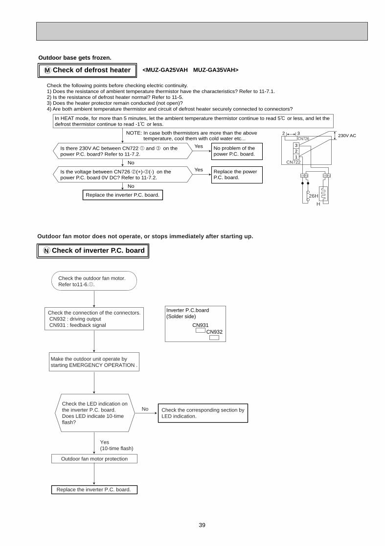
39
Check of defrost heaterM
Replace the inverter P.C. board.
Is there 230V AC between CN722 1 and 3 on the power P.C. board? Refer to 11-7.2.
Yes
No
No problem of the power P.C. board.
Is the voltage between CN726 2(+)-3(-) on the power P.C. board 0V DC? Refer to 11-7.2.
Yes
No
Replace the power P.C. board.
NOTE: In case both thermistors are more than the above temperature, cool them with cold water etc...
In HEAT mode, for more than 5 minutes, let the ambient temperature thermistor continue to read 5: or less, and let the defrost thermistor continue to read -1: or less.
321
230V AC
Check the following points before checking electric continuity.1) Does the resistance of ambient temperature thermistor have the characteristics? Refer to 11-7.1.2) Is the resistance of defrost heater normal? Refer to 11-5.3) Does the heater protector remain conducted (not open)?4) Are both ambient temperature thermistor and circuit of defrost heater securely connected to connectors?
26H
CN726
CN722
H
2121
2 3
Outdoor base gets frozen.
<MUZ-GA25VAH MUZ-GA35VAH>
Check of inverter P .C. boardN
Outdoor fan motor does not operate, or stops immediately after starting up.
Yes(10-time flash)
Check the LED indication onthe inverter P.C. board.Does LED indicate 10-timeflash?
No
Replace the inverter P.C. board.
CN931CN932
Inverter P.C.board(Solder side)
Outdoor fan motor protection
Check the corresponding section byLED indication.
Make the outdoor unit operate bystarting EMERGENCY OPERATION .
Check the connection of the connectors. CN932 : driving output CN931 : feedback signal
Check the outdoor fan motor. Refer to11-6.I.
OB379 --2qxp 05.1.17 16:38 Page 39

40
How to check mis-wiring and serial signal error (when outdoor unit does not work)O
When OPERATION INDICATOR lamp flashes ON and OFF in every 0.5-second.Outdoor unit doesn’t operate.
Is serial signal error indicated 6 minutes later?
No
· Turn OFF inverter-controlled lighting equipment.
· Turn OFF the power supply and then turn ON it again.
· Press EMERGENCY OPERATION switch.
· Reinstall either the unit or the light each other away.
· Attach a filter on receiving section of the indoor unit.
Yes
B
A
Is there rated voltage of230V AC in the powersupply?
In 3 minutes after turning ON thepower supply of the outdoor unit, doesthe LED on the inverter P.C. boardrepeat quick blinking "3.6-second-OFFand 0.8-second-ON"?Be sure to check above in 3 minutesafter turning ON. After 3 minutes, LEDblinks 6 times. When the inverter P.C.board is normal, LED also blinks 6times after 3 minutes.
Is there any mis-wiring, poor contact,or wire disconnectionof theindoor/outdoorconnecting wire?
W1. Mis-wiring may damage indoor electronic control P.C. board during the operation. Be sure to confirm the wiring is correct before the operation starts.
(Lighting)
No
Yes
No
Yes
Yes
No
Yes
No
Yes
No
W2 Be careful to the residual voltage of smoothing capacitor.
Be sure to release the failure-moderecall function after checking.
No
No
Yes
No
YesSerial signal error display
Yes
Yes
No
Yes
As for indoor unit, refer to service manual OB378.
Inverter P.C.board(Parts side)
LED
Blinking
Turn OFF the power supply.
Turn ON the power supply.
Is there 230V AC betweenoutdoor terminal block S1 andS2?
Does the left lamp of OPERATION INDICATOR lamp light up? <Confirmation of the power to the indoor unit>
Press EMERGENCY OPERATION switch.
Check the powersupply.
Is the self-check of the indoor unit displayed 6minutes after?
The left lamp of OPERATION INDICATOR lamp blinks quickly.
A
Turn OFF the power supply.Check once more if the indoor/outdoorconnecting wire is not mis-wiring.Short-circuit outdoor terminal block S2 andS3.W1
B
Turn ON the power supply of the outdoor unit.
Check the wiring.
Make them sure.
Remove the short-circuit betweenoutdoor terminal block S2 and S3.Is there amplitude of 10 to 20V DCbetween outdoor terminal block S2and S3? <Confirmation of serialsignal>
Is there 230V AC between outdoorterminal block S1 and S2?<Confirmation of power voltage>
Replace the indoor electronic control P.C. board.
Replace the inverterP.C. board.W2
Is there any error of theindoor/outdoor connecting wire,such as the damage of the wire,intermediate connection, poorcontact to the terminal block?
Is there any error of theindoor/outdoor connecting wire,such as the damage of the wire,intermediate connection, poorcontact to the terminal block?
Replace theindoor/outdoorconnecting.
Replace theindoor/outdoorconnecting.
OB379 --2qxp 05.1.17 16:38 Page 40
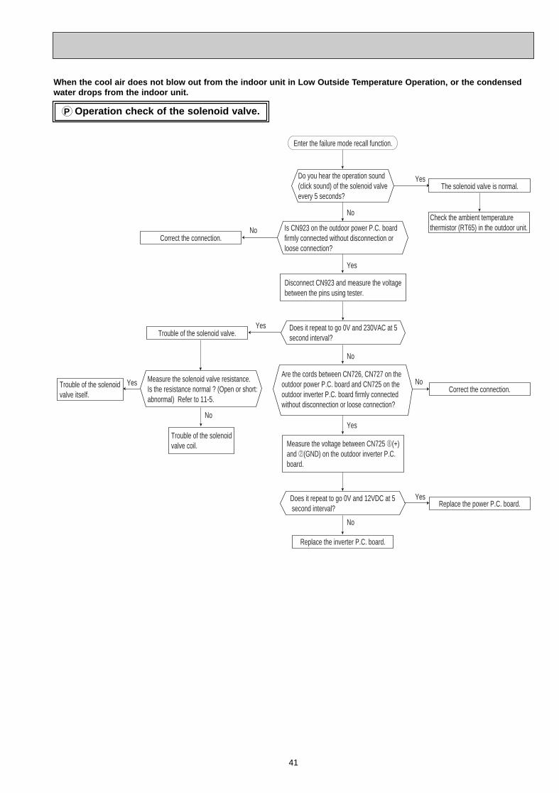
41
Operation check of the solenoid valve.P
Do you hear the operation sound(click sound) of the solenoid valveevery 5 seconds?
Disconnect CN923 and measure the voltagebetween the pins using tester.
Trouble of the solenoidvalve coil.
Are the cords between CN726, CN727 on theoutdoor power P.C. board and CN725 on theoutdoor inverter P.C. board firmly connectedwithout disconnection or loose connection?
Yes
No
Yes
No
Yes
Yes
No
No
Yes
No
No
Yes
Enter the failure mode recall function.
The solenoid valve is normal.
Check the ambient temperaturethermistor (RT65) in the outdoor unit.
Correct the connection.
Trouble of the solenoidvalve itself.
Trouble of the solenoid valve.
Is CN923 on the outdoor power P.C. boardfirmly connected without disconnection orloose connection?
Does it repeat to go 0V and 230VAC at 5second interval?
Correct the connection.
Measure the voltage between CN725 8(+)and 2(GND) on the outdoor inverter P.C.board.
Does it repeat to go 0V and 12VDC at 5 second interval?
Measure the solenoid valve resistance.Is the resistance normal ? (Open or short: abnormal) Refer to 11-5.
Replace the inverter P.C. board.
Replace the power P.C. board.
When the cool air does not blow out from the indoor unit in Low Outside T emperature Operation, or the condensedwater drops from the indoor unit.
OB379 --2qxp 05.1.17 16:38 Page 41
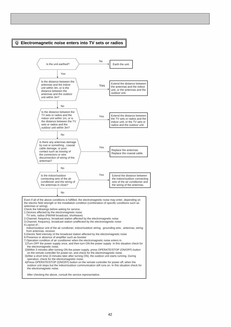
Electromagnetic noise enters into TV sets or radios
42
Q
Replace the antennas.Replace the coaxial cable.
No
No
No
Yes
Yes
No
No
Yes
Yes
Yes
Is the distance between theantennas and the indoorunit within 3m, or is thedistance between theantennas and the outdoorunit within 3m?
Is the distance between theTV sets or radios and theindoor unit within 1m, or isthe distance between the TVsets or radios and theoutdoor unit within 3m?
Is there any antennas damageby rust or something , coaxialcable damage, or poorcontact such as loosing ofthe connectors or wiredisconnection of wiring of theantennas?
Is the indoor/outdoorconnecting wire of the airconditioner and the wiring ofthe antennas in close?
Even if all of the above conditions is fulfilled, the electromagnetic noise may enter, depending on the electric field strength or the installation condition (combination of specific conditions such as antennas or wiring).Check the followings before asking for service.1.Devices affected by the electromagnetic noise TV sets, radios (FM/AM broadcast, shortwave)2.Channel, frequency, broadcast station affected by the electromagnetic noise3.Channel, frequency, broadcast station unaffected by the electromagnetic noise4.Layout of ; indoor/outdoor unit of the air condioner, indoor/outdoor wiring, grounding wire, antennas, wiring from antennas, receiver5.Electric field intensity of the broadcast station affected by the electromagnetic noise6.Presence or absence of amplifier such as booster7.Operation condition of air conditioner when the electromagnetic noise enters in. 1)Turn OFF the power supply once, and then turn ON the power supply. In this situation check for the electromagnetic noise. 2)Within 3 minutes after turning ON the power supply, press OPERATE/STOP (ON/OFF) button on the remote controller for power-on, and check for the electromagnetic noise. 3)After a short time (3 minutes later after turning ON), the outdoor unit starts running. During operation, check for the electromagnetic noise. 4)Press OPERATE/STOP (ON/OFF) button on the remote controller for power off, when the outdoor unit stops but the indoor/outdoor communication still runs on. In this situation check for the electromagnetic noise.
After checking the above, consult the service representative.
Is the unit earthed? Earth the unit.
Extend the distance betweenthe antennas and the indoorunit, or the antennas and theoutdoor unit.
Extend the distance betweenthe TV sets or radios and theindoor unit, or the TV sets orradios and the outdoor unit.
Extend the distance betweenthe indoor/outdoor connectingwire of the air conditioner andthe wiring of the antennas.
OB379 --2qxp 05.1.17 16:38 Page 42
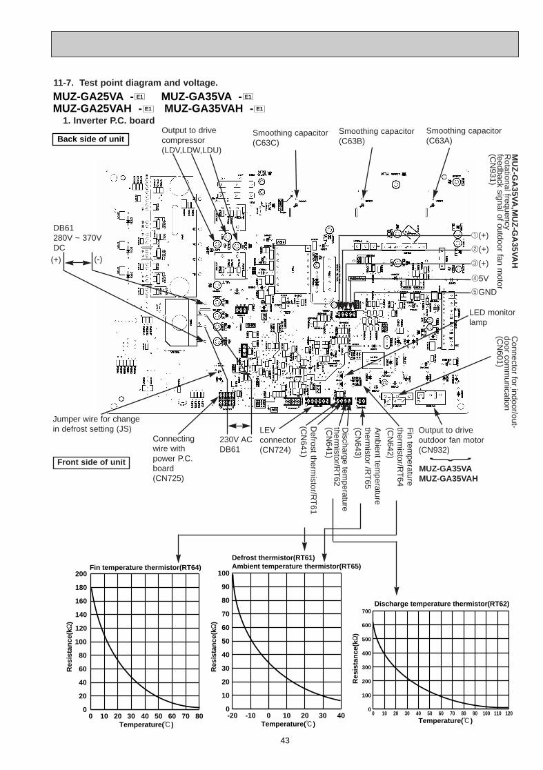
43
MUZ-GA25VA - MUZ-GA35VA -MUZ-GA25VAH - MUZ-GA35VAH - E1E1
E1E1
Back side of unit
-20 -10 0 10 20 30 400
10
20
30
40
50
60
70
80
90
100
Temperature(:)
Ambient temperature thermistor(RT65)Defrost thermistor(RT61)
Temperature(:)
Discharge temperature thermistor(RT62)
0 10 20 30 40 50 60 70 80 90 100 110 1200
100
200
300
400
500
600
700
0 10 20 30 40 50 60 70 800
20
40
60
80
100
120
140
160
180
200
Temperature(:)
Fin temperature thermistor(RT64)
Res
ista
nce
(k"
)
Res
ista
nce
(k"
)
Res
ista
nce
(k"
)
Output to driveoutdoor fan motor(CN932)
Fin tem
peraturetherm
istor/RT
64(C
N642)
Am
bient temperature
thermistor /R
T65
(CN
643)
Discharge tem
peraturetherm
istor/RT
62(C
N641)
Defrost therm
istor/RT
61(C
N641)
LEVconnector(CN724)
230V ACDB61
Connectingwire withpower P.C.board(CN725)
Jumper wire for change in defrost setting (JS)
Front side of unit
DB61280V ~ 370VDC
Smoothing capacitor(C63C)
Smoothing capacitor(C63A)
Smoothing capacitor(C63B)
MU
Z-G
A35V
A,M
UZ
-GA
35VA
HR
otational frequencyfeedback signal of outdoor fan m
otor(C
N931)
1(+)
2(+)
3(+)
45V
5GND
Output to drivecompressor(LDV,LDW,LDU)
LED monitorlamp
Connector for indoor/out-
door comm
unication(C
N601)
(+) (-)
11-7. Test point diagram and voltage.
}
MUZ-GA35VAMUZ-GA35VAH
1. Inverter P .C. board
OB379 --2qxp 05.1.17 16:38 Page 43
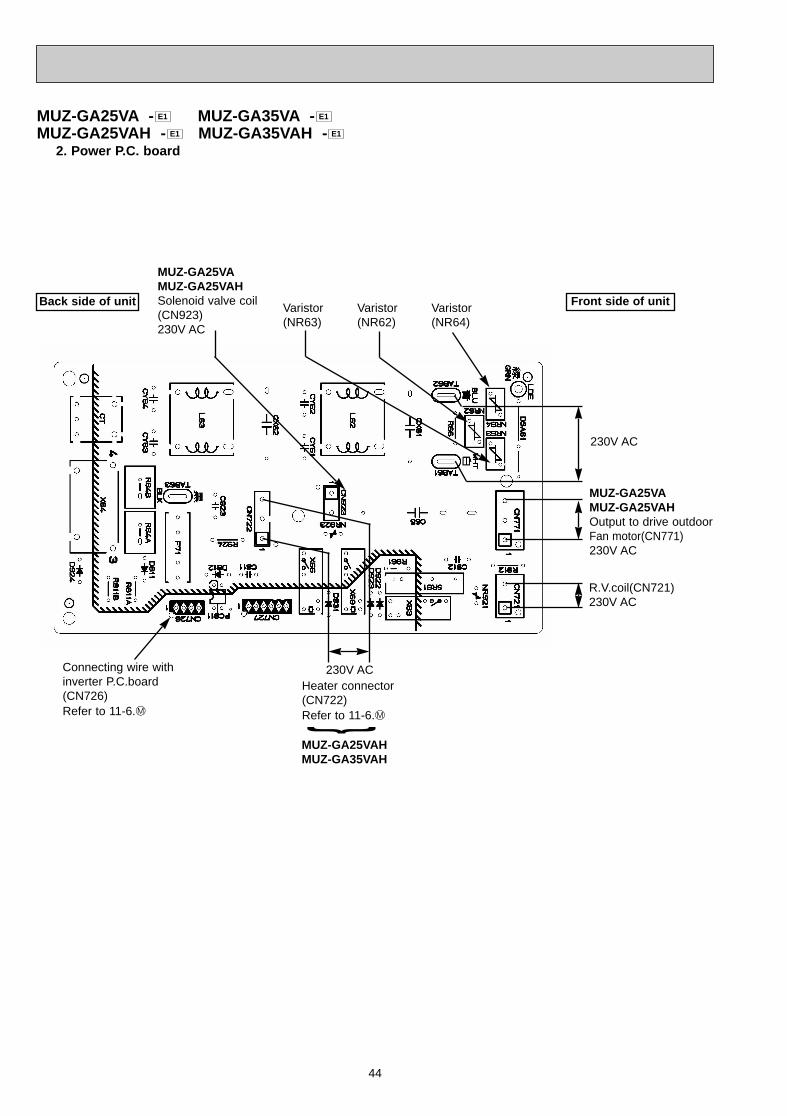
44
Heater connector(CN722) Refer to 11-6.M
R.V.coil(CN721)230V AC
230V AC
Back side of unit
MUZ-GA25VAHMUZ-GA35VAH
}
MUZ-GA25VA - MUZ-GA35VA -MUZ-GA25VAH - MUZ-GA35VAH - E1E1
E1E1
Front side of unit
Connecting wire withinverter P.C.board(CN726)Refer to 11-6.M
230V AC
MUZ-GA25VAMUZ-GA25VAHSolenoid valve coil(CN923) 230V AC
MUZ-GA25VAMUZ-GA25VAHOutput to drive outdoor Fan motor(CN771)230V AC
Varistor (NR63)
Varistor (NR62)
Varistor (NR64)
2. Power P.C. board
OB379 --2qxp 05.1.17 16:38 Page 44
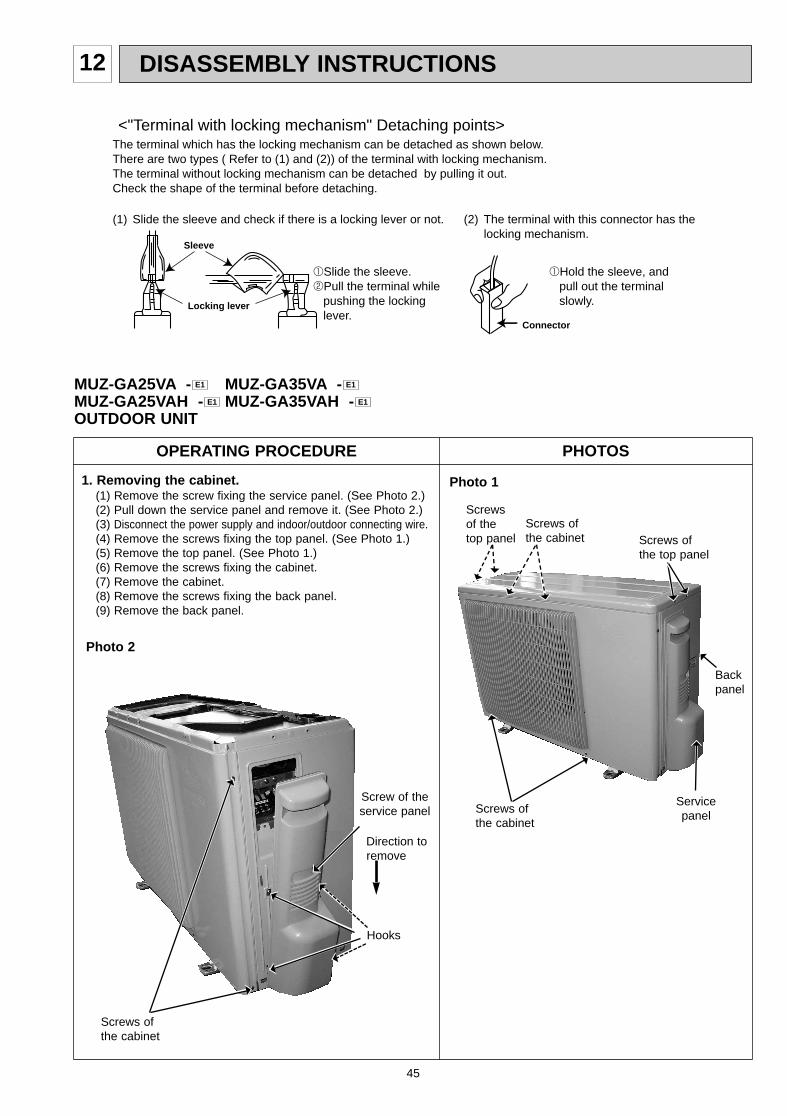
45
12 DISASSEMBLY INSTRUCTIONS
OPERATING PROCEDURE PHOTOS
Photo 11. Removing the cabinet.(1) Remove the screw fixing the service panel. (See Photo 2.)(2) Pull down the service panel and remove it. (See Photo 2.)(3) Disconnect the power supply and indoor/outdoor connecting wire.(4) Remove the screws fixing the top panel. (See Photo 1.)(5) Remove the top panel. (See Photo 1.)(6) Remove the screws fixing the cabinet.(7) Remove the cabinet.(8) Remove the screws fixing the back panel.(9) Remove the back panel.
Screws of the cabinet
(1) Slide the sleeve and check if there is a locking lever or not. (2) The terminal with this connector has the locking mechanism.
1Slide the sleeve.2Pull the terminal while pushing the locking lever.
1Hold the sleeve, and pull out the terminal slowly.
The terminal which has the locking mechanism can be detached as shown below.There are two types ( Refer to (1) and (2)) of the terminal with locking mechanism.The terminal without locking mechanism can be detached by pulling it out.Check the shape of the terminal before detaching.
<"Terminal with locking mechanism" Detaching points>
Connector
Sleeve
Locking lever
Photo 2
Screw of theservice panel
Direction toremove
Hooks
Back panel
Servicepanel
MUZ-GA25VA - MUZ-GA35VA -MUZ-GA25VAH - MUZ-GA35VAH -OUTDOOR UNIT
E1E1
E1E1
Screws of the cabinet
Screws ofthe top panel
Screws of the cabinet
Screws of the top panel
OB379 --2qxp 05.1.17 16:38 Page 45
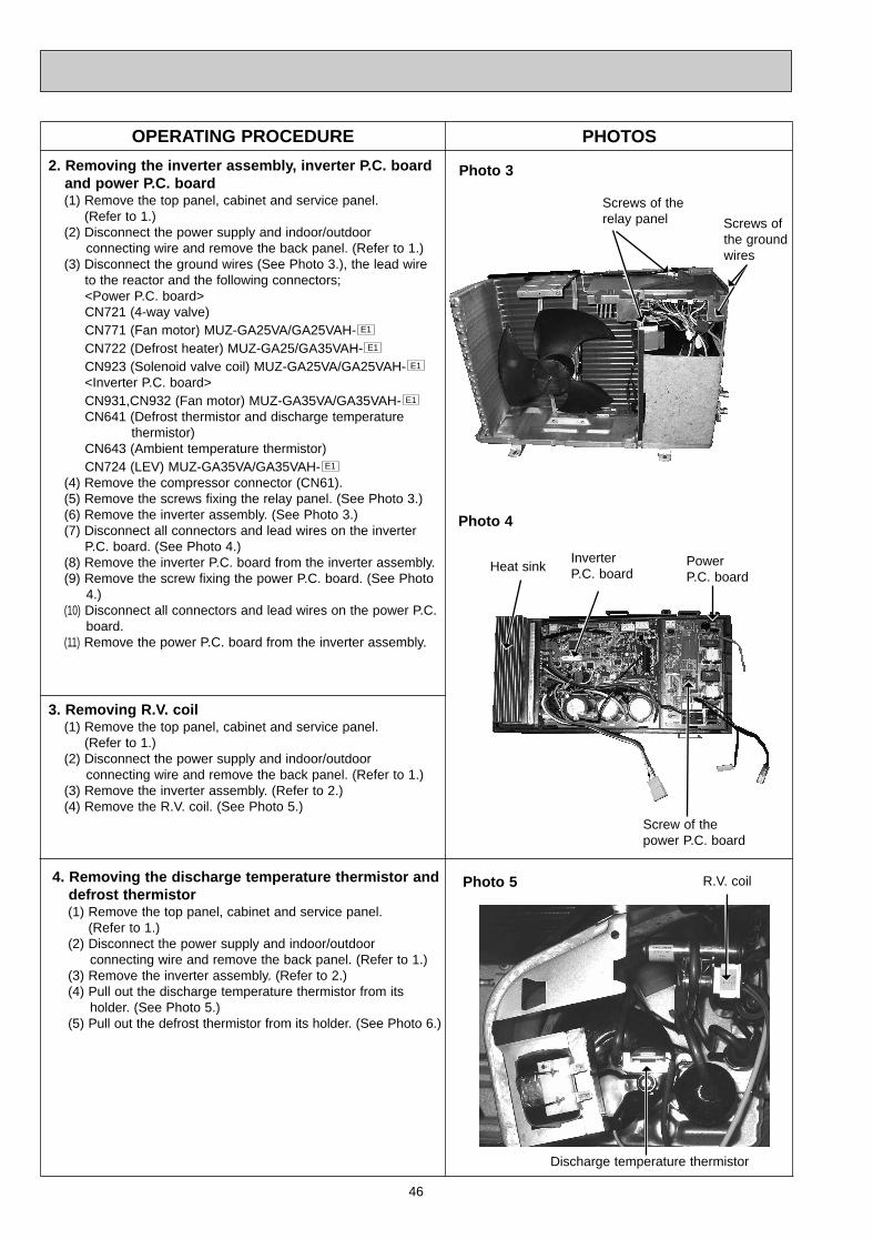
3. Removing R.V . coil (1) Remove the top panel, cabinet and service panel.
(Refer to 1.)(2) Disconnect the power supply and indoor/outdoor
connecting wire and remove the back panel. (Refer to 1.)(3) Remove the inverter assembly. (Refer to 2.)(4) Remove the R.V. coil. (See Photo 5.)
46
OPERATING PROCEDURE PHOTOS
2. Removing the inverter assembly , inverter P .C. boardand power P .C. board (1) Remove the top panel, cabinet and service panel.
(Refer to 1.)(2) Disconnect the power supply and indoor/outdoor
connecting wire and remove the back panel. (Refer to 1.)(3) Disconnect the ground wires (See Photo 3.), the lead wire
to the reactor and the following connectors;<Power P.C. board>CN721 (4-way valve)CN771 (Fan motor) MUZ-GA25VA/GA25VAH-CN722 (Defrost heater) MUZ-GA25/GA35VAH-CN923 (Solenoid valve coil) MUZ-GA25VA/GA25VAH-<Inverter P.C. board>CN931,CN932 (Fan motor) MUZ-GA35VA/GA35VAH-CN641 (Defrost thermistor and discharge temperature
thermistor)CN643 (Ambient temperature thermistor) CN724 (LEV) MUZ-GA35VA/GA35VAH-
(4) Remove the compressor connector (CN61).(5) Remove the screws fixing the relay panel. (See Photo 3.)(6) Remove the inverter assembly. (See Photo 3.)(7) Disconnect all connectors and lead wires on the inverter
P.C. board. (See Photo 4.)(8) Remove the inverter P.C. board from the inverter assembly.(9) Remove the screw fixing the power P.C. board. (See Photo
4.)(10) Disconnect all connectors and lead wires on the power P.C.
board.(11) Remove the power P.C. board from the inverter assembly.
E1
E1
E1
E1
E1
Photo 3
Photo 4
Screw of thepower P.C. board
Heat sinkInverterP.C. board
PowerP.C. board
Screws ofthe groundwires
Screws of therelay panel
4. Removing the discharge temperature thermistor anddefrost thermistor(1) Remove the top panel, cabinet and service panel.
(Refer to 1.)(2) Disconnect the power supply and indoor/outdoor
connecting wire and remove the back panel. (Refer to 1.)(3) Remove the inverter assembly. (Refer to 2.)(4) Pull out the discharge temperature thermistor from its
holder. (See Photo 5.)(5) Pull out the defrost thermistor from its holder. (See Photo 6.)
Photo 5
Discharge temperature thermistor
R.V. coil
OB379 --2qxp 05.1.17 16:38 Page 46
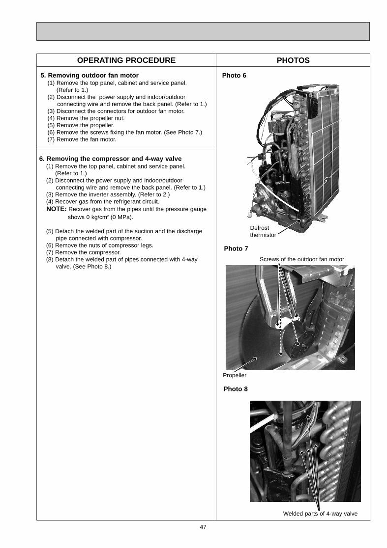
47
OPERATING PROCEDURE PHOTOS
Photo 6
Photo 7
Defrostthermistor
5. Removing outdoor fan motor(1) Remove the top panel, cabinet and service panel.
(Refer to 1.)(2) Disconnect the power supply and indoor/outdoor
connecting wire and remove the back panel. (Refer to 1.)(3) Disconnect the connectors for outdoor fan motor.(4) Remove the propeller nut.(5) Remove the propeller.(6) Remove the screws fixing the fan motor. (See Photo 7.)(7) Remove the fan motor.
Photo 8
Welded parts of 4-way valve
6. Removing the compressor and 4-way valve(1) Remove the top panel, cabinet and service panel.
(Refer to 1.)(2) Disconnect the power supply and indoor/outdoor
connecting wire and remove the back panel. (Refer to 1.)(3) Remove the inverter assembly. (Refer to 2.)(4) Recover gas from the refrigerant circuit.NOTE: Recover gas from the pipes until the pressure gauge
shows 0 kg/cm2 (0 MPa).
(5) Detach the welded part of the suction and the dischargepipe connected with compressor.
(6) Remove the nuts of compressor legs.(7) Remove the compressor.(8) Detach the welded part of pipes connected with 4-way
valve. (See Photo 8.)
Propeller
Screws of the outdoor fan motor
OB379 --2qxp 05.1.17 16:38 Page 47
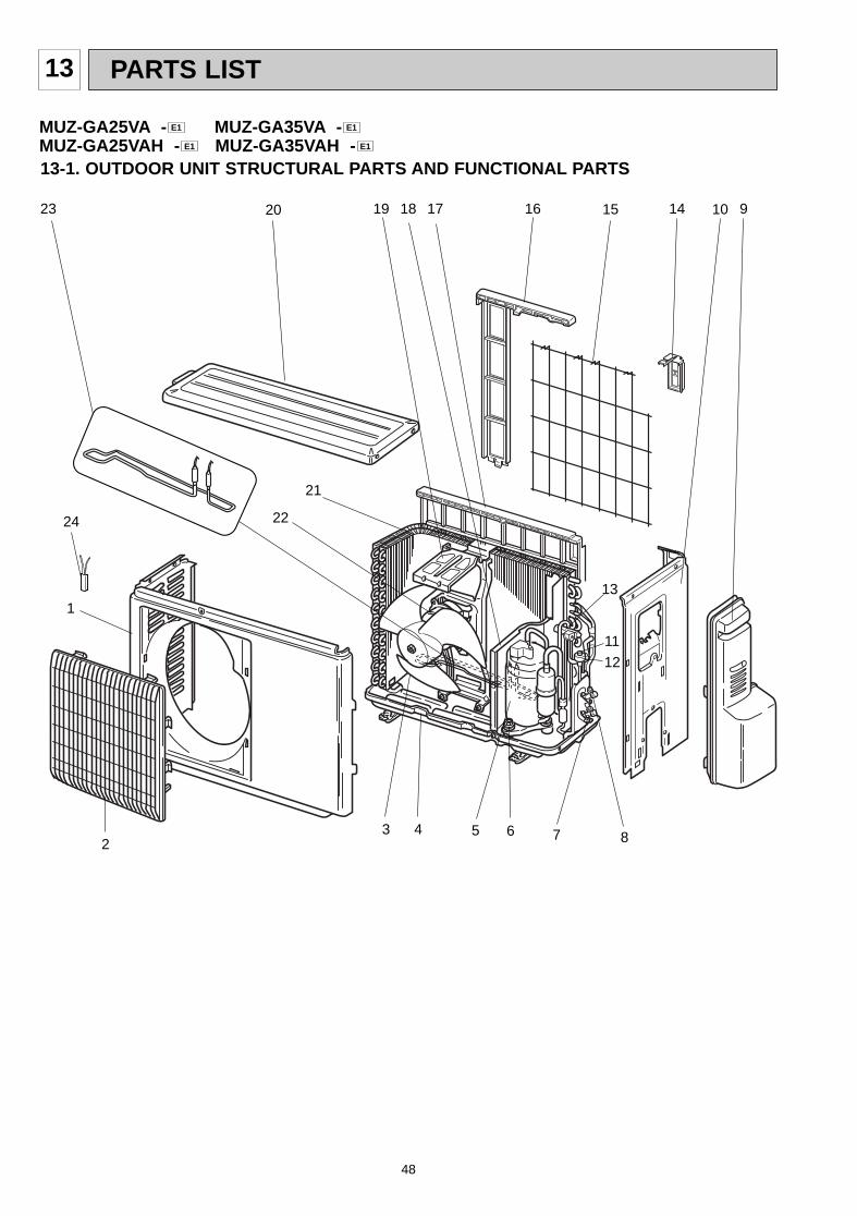
48
13 PARTS LIST
13-1. OUTDOOR UNIT STRUCTURAL PARTS AND FUNCTIONAL PARTS
1
11
12
2
1820
13
10 9
MUZ-GA25VA - MUZ-GA35VA -MUZ-GA25VAH - MUZ-GA35VAH - E1E1
E1E1
3 4 5 6 7 8
19 1723
21
2224
15 1416
OB379 --2qxp 05.1.17 16:38 Page 48
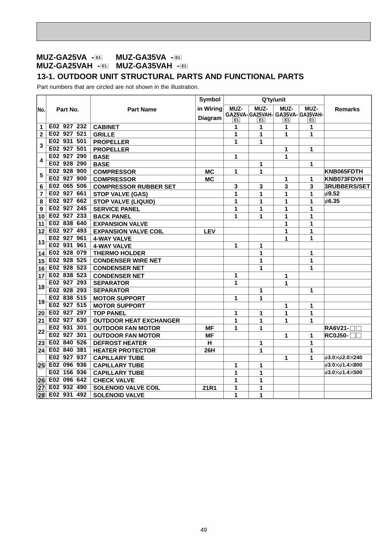
49
12
3
4
5
6789101112
13
14151617
18
19
2021
22
2324
25
262728
KNB065FDTHKNB073FDVH3RUBBERS/SET{9.52{6.35
RA6V21-RC0J50-
{3.0✕{2.0✕240{3.0✕{1.4✕800{3.0✕{1.4✕500
MCMC
LEV
MFMFH
26H
21R1
111
1
1
31111
1
11
1
111
11111
111
11
31111
1111
11
111
11
11111
11
11
131111111
11
111
1
1
11
1
1
131111111
111
1
111
1111
Symbol
in Wiring
Diagram
Q'ty/unit
RemarksPart No.No. Part Name MUZ- GA25VA-
E1
MUZ-GA35VA-
E1
MUZ-GA25VAH-
E1
MUZ-GA35VAH-
E1
CABINETGRILLEPROPELLERPROPELLERBASEBASECOMPRESSORCOMPRESSORCOMPRESSOR RUBBER SETSTOP VALVE (GAS)STOP VALVE (LIQUID)SERVICE PANELBACK PANELEXPANSION VALVEEXPANSION VALVE COIL4-WAY VALVE4-WAY VALVETHERMO HOLDERCONDENSER WIRE NETCONDENSER NETCONDENSER NETSEPARATORSEPARATORMOTOR SUPPORTMOTOR SUPPORTTOP PANELOUTDOOR HEAT EXCHANGEROUTDOOR FAN MOTOROUTDOOR FAN MOTORDEFROST HEATERHEATER PROTECTORCAPILLARY TUBECAPILLARY TUBECAPILLARY TUBECHECK VALVESOLENOID VALVE COILSOLENOID VALVE
E02 927 232E02 927 521E02 931 501E02 927 501E02 927 290E02 928 290E02 928 900E02 927 900E02 065 506E02 927 661E02 927 662E02 927 245E02 927 233E02 838 640E02 927 493E02 927 961E02 931 961E02 928 079E02 928 525E02 928 523E02 838 523E02 927 293E02 928 293E02 838 515E02 927 515E02 927 297E02 927 630E02 931 301E02 927 301E02 840 526E02 840 381E02 927 937E02 096 936E02 156 936E02 096 642E02 932 490E02 931 492
Part numbers that are circled are not shown in the illustration.
13-1. OUTDOOR UNIT STRUCTURAL PARTS AND FUNCTIONAL PARTS
MUZ-GA25VA - MUZ-GA35VA -MUZ-GA25VAH - MUZ-GA35VAH - E1E1
E1E1
OB379 --2qxp 05.1.17 16:38 Page 49
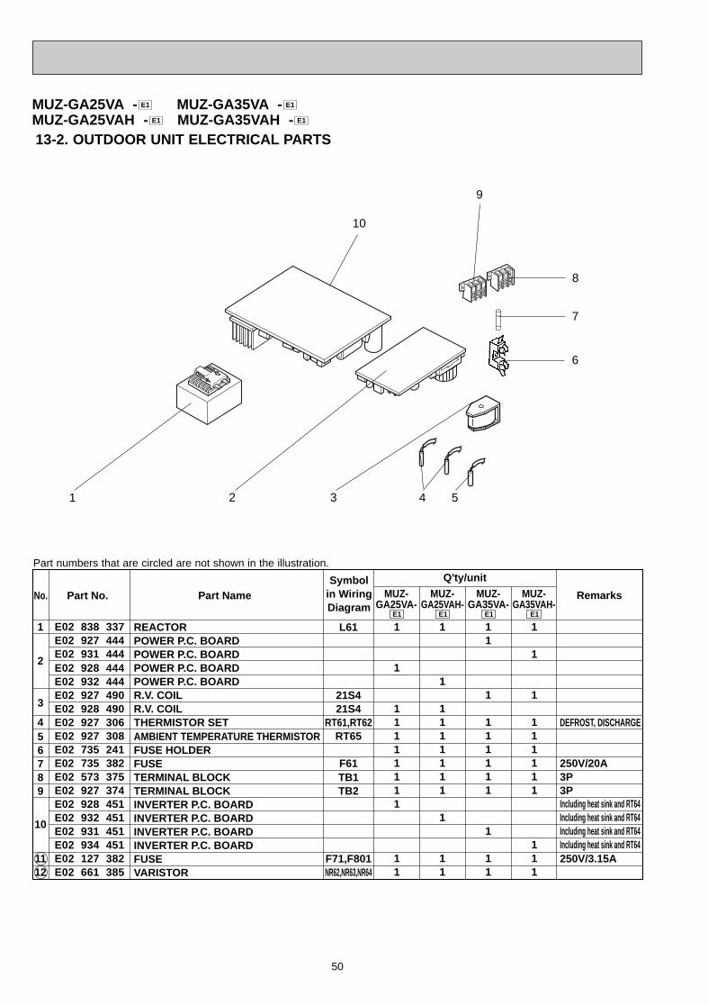
50
13-2. OUTDOOR UNIT ELECTRICAL PARTS
10
6
1 4
REACTORPOWER P.C. BOARDPOWER P.C. BOARDPOWER P.C. BOARDPOWER P.C. BOARDR.V. COILR.V. COILTHERMISTOR SETAMBIENT TEMPERATURE THERMISTORFUSE HOLDERFUSETERMINAL BLOCKTERMINAL BLOCKINVERTER P.C. BOARDINVERTER P.C. BOARDINVERTER P.C. BOARDINVERTER P.C. BOARDFUSEVARISTOR
E02 838 337E02 927 444E02 931 444E02 928 444E02 932 444E02 927 490E02 928 490E02 927 306E02 927 308E02 735 241E02 735 382E02 573 375E02 927 374E02 928 451E02 932 451E02 931 451E02 934 451E02 127 382E02 661 385
1
2
3
456789
10
1112
Symbolin WiringDiagram
Q'ty/unit
DEFROST, DISCHARGE
250V/20A3P3PIncluding heat sink and RT64Including heat sink and RT64Including heat sink and RT64Including heat sink and RT64250V/3.15A
RemarksPart No.No. Part Name
L61
21S421S4
RT61,RT62RT65
F61TB1TB2
F71,F801NR62,NR63,NR64
1
1
11111111
11
1
1
1111111
1
11
11
1
111111
1
11
1
1
1
111111
111
MUZ-GA25VA-
E1
MUZ-GA25VAH-
E1
MUZ-GA35VA-
E1
MUZ-GA35VAH-
E1
MUZ-GA25VA - MUZ-GA35VA -MUZ-GA25VAH - MUZ-GA35VAH - E1E1
E1E1
2 3 5
7
8
9
Part numbers that are circled are not shown in the illustration.
OB379 --2qxp 05.1.17 16:38 Page 50
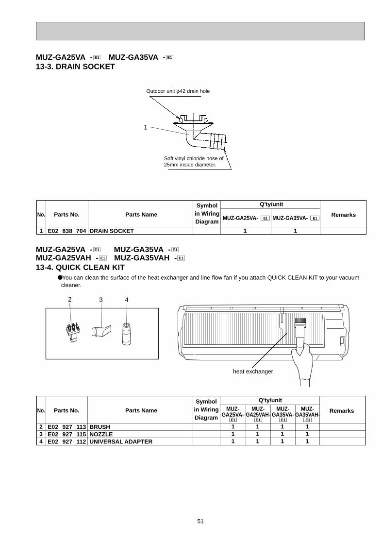
51
Outdoor unit {42 drain hole
Soft vinyl chloride hose of25mm inside diameter.
MUZ-GA25VA - MUZ-GA35VA -13-3. DRAIN SOCKET
E1E1
Symbolin WiringDiagram
Q'ty/unit
MUZ-GA25VA- RemarksParts No. Parts NameE1 MUZ-GA35VA- E1
E02 838 7041 DRAIN SOCKET
No.
1 1
1
13-4. QUICK CLEAN KIT●You can clean the surface of the heat exchanger and line flow fan if you attach QUICK CLEAN KIT to your vacuum
cleaner.
heat exchanger
Symbolin WiringDiagram
RemarksParts No. Parts Name
E02 927 113E02 927 115E02 927 112
234
BRUSHNOZZLEUNIVERSAL ADAPTER
No.
Q'ty/unit
111
111
111
111
MUZ-GA25VA-
E1
MUZ-GA25VAH-
E1
MUZ-GA35VA-
E1
MUZ-GA35VAH-
E1
2 43
MUZ-GA25VA - MUZ-GA35VA -MUZ-GA25VAH - MUZ-GA35VAH - E1E1
E1E1
OB379 --2qxp 05.1.17 16:38 Page 51

HEAD OFFICE: MITSUBISHI DENKI BLDG., 2-2-3, MARUNOUCHI, CHIYODA-KU, TOKYO100-8310, JAPAN
CC Copyright 2005 MITSUBISHI ELECTRIC ENGINEERING CO.,L TDDistributed in Jan. 2005. No. OB379 6Made in Japan
New publication, effective Jan. 2005Specifications subject to change without notice.
OB379 --2qxp 05.1.17 16:38 Page 52