sportster 33.6 kbps internal and external modems -...
TRANSCRIPT

This manual covers installation and operating instructions for the following 3Com modems:
Sportster® 33.6 kbps internal and external modems
3Com, the 3Com logo, U.S. Robotics, the USRobotics logo, and Sportster are registeredtrademarks; Connections, Total Control, Courier, RapidComm, x2, and the x2 logo are trademarksand Towne Square 2000 is a service mark of 3Com Corporation or its subsidiaries. Windows andInternet Explorer are registered trademarks of Microsoft Corp. CompuServe is a registeredtrademark of CompuServe Inc. America Online is a registered trademark of America Online Inc.Netscape Navigator is a trademark of Netscape Communications Corp. Any other trademarks, tradenames, or service marks used in this manual are the property of their respective owners.
Copyright © 1997 3Com Corporation or its subsidiaries7770 North Frontage RoadSkokie, IL 60077-2690All Rights Reserved

TABLE OF CONTENTS
ii
Before You Begin (Windows 95 Users) 1Internal Modem Installation with Windows 3.x 4
A Word about COM Ports and IRQs 4How to Use ComTest to Determine Your Modem’s Settings 6Testing an Installed Modem 9What to Do with ComTest’s Recommendation 9How to Change the Modem’s Settings 12How to Insert the Modem into the Computer 14
Internal Modem Installation with Windows 95 21Plug and Play Installation 21How to Prepare for Plug and Play Installation 21How to Insert the Modem into the Computer 23Installing the Modem Drivers 27
External Modem Installation with Windows 3.x 35How to Determine Which Serial Cable to Buy 35How to Connect the Modem to the Computer 36

TABLE OF CONTENTS
iii
External Modem Installation with Windows 95 39How to Determine Which Serial Cable to Buy 39How to Connect the Modem to the Computer 40Installing the Modem Drivers 42
Manual Modem Installation 50Software Installation and Testing 58
Software Installation and Registration Using the Setup Wizard 58Sending Your First Fax 74
Installing Other Fax/Data Software 77Type of Modem 77Initialization String 77Flow Control 77UART (External Modems Only) 78
Using Modem Station 79Why Modem Station? 79What Does Modem Station Do? 79Installing Modem Station 79Starting Modem Station 82Using Detect New Modems 84Using Terminal 86Using Modem Configurator 88

TABLE OF CONTENTS
iv
Using Modem to Computer 91Using the Extended Information Screens 96
U.S. Robotics Modem Update Wizard 103Installation 103Operation 108
Troubleshooting and Online Help Resources 116Online Help Resources 122Are You Still Having Problems? 126If You Need to Return the Modem to Us 127RapidComm Troubleshooting Tips 127A Note to Users with Older Versions of RapidComm on Their Systems 128
Glossary 129Technical Quick Reference 143
Front Panel Lights (External Modems) 144Command Summary 145DIP Switches (Modems with DIP Switches Only) 160S-Registers 162The Serial Interface 172
Regulatory Information 174Manufacturer’s Declaration of Conformity 174
Caution to the User 175

TABLE OF CONTENTS
v
IC (Canada) 175UL Listing/CUL Listing 175Connecting to the Telephone Company 175Fax Branding 176Radio and Television Interference 176For Canadian Modem Users 178Limited Warranty 181
Index 184

BEFORE YOU BEGIN
1
Your Sportster modem is a Plug and Playdevice. Windows® 95 can automaticallyidentify a Plug and Play device and determine ifyour system has the resources necessary tosupport the device. However, Plug and Playwill not work if you do not have resourcesavailable or if devices on your system are notreporting resource usage correctly. Here’show you can verify that your system has thenecessary resources before installing themodem.
1. Click the Windows 95 Start button, pointto Settings, and then click Control Panel.
2. Double-click the System icon.
3. When the “System Properties” screenappears, click the Device Manager tab.
4. Double-click Computer and the“Computer Properties” screen appears.
5. Select the option at the top of the screen toshow Interrupt Requests (IRQs).
You will see the IRQs your system is currentlyusing. If IRQs 3, 4, 5, and 7 are being used,you need to free an IRQ before you begininstallation. This process involves moving adevice from the IRQ you want to use to adifferent (and usually higher) IRQ setting.Please read the documentation for (or contactthe manufacturer of) the device that is currentlyusing the IRQ you want to use for your modemto learn more about what you should do to freethe IRQ for your modem.
Be sure to read the section titled “U.S.Robotics Modem Update Wizard” on page101 for information on upgrading your 33.6faxmodem to x2™ technology, allowingdownloads of up to 56 kbps.

BEFORE YOU BEGIN
2
Determining Your Version ofWindows 95
Follow these steps to determine your versionof Windows 95. This information will beimportant during installation.
1. Click the My Computer icon on yourdesktop with the right mouse button.
2. Click Properties.
3. In the “System Properties” screen, look atthe system information under the Generaltab (circled in the following screen image).
The number following the text “MicrosoftWindows 95” will end with “950”, “950a”,or “950b”. This indicates your version ofWindows 95. Write this number on theblank below for later reference. Then clickOK.
Windows 95 version _________________

BEFORE YOU BEGIN
3
Upgrading to x2™ TechnologyBe sure to read the section titled “U.S.Robotics Modem Update Wizard” on page101 for information on upgrading your 33.6faxmodem to x2™ technology, allowingdownloads of up to 56 kbps*.∗ IMPORTANT! All x2 products are capable of 56
kbps downloads; however, due to FCC rules which restrictpower output of the service providers' modems, currentdownload speeds are limited to 53 kbps. Actual speedsmay vary depending on line conditions. Uploads fromusers to service providers travel at speeds up to 28.8kbps. An x2-capable modem, an x2-compatible analogphone line, and an x2-capable Internet Service Provider arenecessary for these high-speed downloads.

INTERNAL MODEM INSTALLATION WITH WINDOWS®
3.X
4
You’ll need these items from yourSportster ® modem box:
modem phone cord
Connections™ CD
Plus:
a screwdriver (not included)
A Word about COM Portsand IRQsMost computer accessories — a mouse,sound card, enhanced graphics card, scanner,etc. — require a special connection throughwhich they can communicate with thecomputer. For some devices, this connection iscalled a communications (or COM) port. Mostcomputers have 1 or 2 COM ports, but theycan have up to 4. Although internal modemsdo not connect to COM ports directly, they dorequire a COM port setting, which isdetermined by the setting on the modem’sCOM jumper pins.
INTERNAL MODEM INSTALLATION WITH WINDOWS 3.X
5
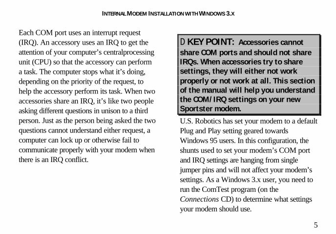
Each COM port uses an interrupt request(IRQ). An accessory uses an IRQ to get theattention of your computer’s centralprocessingunit (CPU) so that the accessory can performa task. The computer stops what it’s doing,depending on the priority of the request, tohelp the accessory perform its task. When twoaccessories share an IRQ, it’s like two peopleasking different questions in unison to a thirdperson. Just as the person being asked the twoquestions cannot understand either request, acomputer can lock up or otherwise fail tocommunicate properly with your modem whenthere is an IRQ conflict.
D KEY POINT: Accessories cannotshare COM ports and should not shareIRQs. When accessories try to sharesettings, they will either not workproperly or not work at all. This sectionof the manual will help you understandthe COM/IRQ settings on your newSportster modem.
U.S. Robotics has set your modem to a defaultPlug and Play setting geared towardsWindows 95 users. In this configuration, theshunts used to set your modem’s COM portand IRQ settings are hanging from singlejumper pins and will not affect your modem’ssettings. As a Windows 3.x user, you need torun the ComTest program (on theConnections CD) to determine what settingsyour modem should use.

INTERNAL MODEM INSTALLATION WITH WINDOWS 3.X
6
NOTE: Some communicationssoftware programs require a particularsetting for your modem (RapidComm,which shipped with your modem, doesnot). If you wish to use a program otherthan RapidComm, now is a good time toread that software’s manual todetermine what setting is required.
How to Use ComTest toDetermine Your Modem’sSettings
1. Insert the Connections CD into your CD-ROM drive.
2. In Windows’ Program Manager, click Runon the File menu. Type d:\comtest.exeand press ENTER. This starts ComTest,
the program that determines which COMports and IRQs are available for use byyour modem.
3. The screen in the next column appearswhen ComTest starts.
• If there is a modem in your computerwhich you are replacing with your newSportster modem, go to “Testing anInstalled Modem” on page 7 todetermine which COM and IRQ settingsthe older modem is using.
• If a modem is not currently installed inyour computer, click Recommendsettings for a new modem.

INTERNAL MODEM INSTALLATION WITH WINDOWS 3.X
7
Then click Next.
4. Click Internal Modem. Then click Next.
5. If you have a free setting, you will see ascreen like this.
COM2/IRQ3 is free in this example.ComTest might instead recommendCOM1/IRQ4, COM3/IRQ4, orCOM4/IRQ3 for your modem.
Write down the displayed settings in thespaces provided on the first page of thismanual. You’ll need to know these settingslater. Click Next.

INTERNAL MODEM INSTALLATION WITH WINDOWS 3.X
8
If you do not have a free setting, you willsee a screen like this.
Click Finish to exit ComTest. Go to “Whatto Do with ComTest’s Recommendation”on page 8.
6. When you see this screen, click Finish toexit ComTest.
Go to “What to Do with ComTest’sRecommendation” on page 8.

INTERNAL MODEM INSTALLATION WITH WINDOWS 3.X
9
Testing an Installed ModemIf there is a modem already installed in yourcomputer, you can determine its COM andIRQ settings by selecting the Test aninstalled modem option. Follow theinstructions on screen until you see the screenthat tells you “Testing is complete.” This screenwill also tell you which COM and IRQ settingsyour present modem is using. These are thesettings you want to use for your newSportster modem. Write the settings down inthe spaces provided on the first page of thismanual.
Turn off and unplug your computer andremove your present modem. Go to “How toChange the Modem’s Settings” on page 10.
What to Do with ComTest’sRecommendation
NOTE: If your communicationssoftware requires a modem thatComTest does not recommend, there isa good chance that the setting is beingused by another device in your system.To free that setting in your system,consult your computer’s manual. Go to“How to Change the Modem’s Settings”on page 10.
If ComTest recommended COM1/IRQ4
Write “COM1” and “IRQ4” in the spacesprovided on the first page of this manual. Go to“How to Change the Modem’s Settings” onpage 10.

INTERNAL MODEM INSTALLATION WITH WINDOWS 3.X
10
If ComTest recommended COM2/IRQ3
Write “COM2” and “IRQ3” in the spacesprovided on the first page of this manual. Go to“How to Change the Modem’s Settings” onpage 10.
If ComTest recommended COM3/IRQ4or COM4/IRQ3
Do not use either of these settings. While theCOM port part of the setting is acceptable(ComTest only recommends COM ports thatare not being used), the IRQ part of the settingis not acceptable. When ComTestrecommends either COM3/IRQ4 orCOM4/IRQ3, the IRQ in the setting is beingused by another accessory. You could use thesuggested IRQ for the modem, but you run therisk that the modem and/or the other accessorysharing the IRQ might not work properly.
If you do not have a sound card, useCOM3/IRQ5. Write “COM3” and “IRQ5”in the spaces provided on the first page ofthis manual. You will have to change thesettings on your modem. Go to “How toChange the Modem’s Settings” on page 10.
If you do have a sound card, useCOM2/IRQ3. To use this setting, you have tofirst disable your computer’s second serial port(COM2). This is a pronged socket on theback of your computer.• Go to your computer manufacturer’s
manual.• Find out how to disable the COM port.• Find out which of the sockets on the back
of your computer is the second serial port.• If you have something plugged into that
port, find out if you can plug it insomewhere else. Any accessory plugged

INTERNAL MODEM INSTALLATION WITH WINDOWS 3.X
11
into that port will not work after the porthas been disabled.
• Then return to this point in this manual tocontinue.
After disabling COM2, you can use theCOM2/IRQ3 setting.
Write “COM2” and “IRQ3” on the first pageof this manual and go to “How to Change theModem’s Settings” on page 10.
If ComTest reports that “You do nothave any available COM ports and/orIRQs”
We recommend you disable COM1 orCOM2. When you disable one of these COMports, you can use it and its default IRQ foryour modem. Go to your computermanufacturer’s manual.
• Find out which socket is COM1 and whichis COM2.
• If nothing is plugged into either port, youmay choose either of the ports to disable.Your computer manufacturer’s manual willtell you how to disable the COM port.
• If one port does not have anything pluggedinto it, note if the port is COM1 or COM2.This is the port you’ll want to disable foryour modem.
• If both ports are being used, you may beable to attach one of the plugged-inaccessories elsewhere so that you candisable its COM port. The accessory willnot work once its port is disabled.
If you’ve disabled COM1, you can now usethe COM1/IRQ4 setting. Write it down on thefirst page of this manual. Go to “How toChange the Modem’s Settings” (on this page).

INTERNAL MODEM INSTALLATION WITH WINDOWS 3.X
12
If you’ve disabled COM2, you can now usethe COM2/IRQ3 setting. Write the settingdown on the first page of this manual.
How to Change the Modem’sSettings1. Always touch an unpainted metal part of
your computer (the back is usuallyunpainted) to discharge static electricitybefore handling the modem. Static candamage your modem. Then take themodem out of its plastic bag.
2. Find the COM and IRQ jumper shunts(small black plastic pieces) on yourmodem’s jumper pins (see the followingdiagram).
3. To change the COM port and IRQ settings,you need to reposition the jumper shunts onthe COM port and IRQ pins. To do this, liftthe jumper shunts off the pins.

INTERNAL MODEM INSTALLATION WITH WINDOWS 3.X
13
TIP: Grasp the jumper shunts witha tweezers or needle-nosed pliers. DONOT grasp too firmly, as you may crushthe jumper shunts. If a jumper shuntseems stuck, gently rock it back andforth as you lift. Do not touch any otherpart of the modem or your computerwith the tweezers/pliers. A jumpershunt needs to be sitting on bothjumper pins in order to effectively setthe modem to the desired setting.
4. Move the jumper shunt to the new setting.• The COM port setting can involve one
to three shunts. The four possible COMport settings are as follows:
0 1 SEL COM 1
0 1 SEL COM 3
0 1 SELCOM 4
0 1 SELCOM 2
• Unlike most COM port settings, theIRQ setting involves only one jumpershunt. Simply move the jumper shunt tothe pins labeled with the IRQ you need.

INTERNAL MODEM INSTALLATION WITH WINDOWS 3.X
14
How to Insert the Modeminto the Computer
NOTE: Before installing yourmodem, write its serial number in thespace provided on the first page ofthis manual. (You’ll find the serialnumber underneath the bar code onthe white sticker on the modem and onthe outside of the box the modemcame in.) If you ever need to call ourcustomer support department, acustomer support representative willask you for the serial number. Thiswill help him or her identify yourmodem.
1. Turn off your computer and unplug it fromthe electrical outlet.
2. Unplug any peripheral devices (printer,monitor, keyboard, mouse, etc.) from thecomputer.
TIP: Before you unplug anything,label the cords or make a sketch of howthings are connected. This can behelpful when you plug things back inlater.
CAUTION : To avoid the risk ofelectric shock, make sure your computerand all peripheral devices are turned offand unplugged.

INTERNAL MODEM INSTALLATION WITH WINDOWS 3.X
15
3. Remove the screws from your computer’scover and then remove the cover, as shownin the following diagrams. Your computermay differ in appearance from thesediagrams, but the basic principle forremoving the cover should be the same.Contact your computer manufacturer orreview their manual if you need furtherinstructions.
4. Find an empty ISA expansion slot at leastas long as the gold edge of your modem.(ISA slots have black plastic grooves linedwith silver.) Unscrew and remove theexpansion slot cover (the long narrow pieceof metal that keeps dust from enteringthrough the opening perpendicular to theslot). Be careful not to drop the screw intothe computer. You will need it later toscrew the modem into place.

INTERNAL MODEM INSTALLATION WITH WINDOWS 3.X
16
5. Holding the modem at each corner, with thegold edge facing the slot, push the modemdown as gently as possible until it snaps intothe expansion slot. (NOTE: The drawingsshow horizontally aligned expansion slots.Some computers have vertically alignedslots. The instructions apply to both styles.)
You need to apply a little pressure to seatthe modem properly. Sometimes a gentleback-and-forth motion helps to fit the
modem all the way into the slot. If you feelresistance, the modem may not be properlylined up with the slot. Do not force it intothe slot. Remove the modem and try again.
6. Once the modem is in place, fasten it firmlyinto place using the screw that you removedin step 4.

INTERNAL MODEM INSTALLATION WITH WINDOWS 3.X
17
7. Replace the computer’s cover and fasten itwith the screws you removed in step 3.
8. If you currently have a phone plugged intothe wall jack you plan to use for themodem, disconnect the phone’s cord fromthe jack.
WARNING : The phone jack youuse must be for an ANALOG phone line(the type found in most homes). Manyoffice buildings have digital phonelines. Be sure you know which type ofline you have. The modem will bedamaged if you use a digital phone line.
9. Plug one end of the phone cord that camewith the modem into the TELCO jack atthe rear of the modem. Plug the other endof the cord into the wall jack.
10. If you wish to use a phone through the linethe modem uses (when the modem is not inuse), plug your phone’s cord into themodem’s PHONE jack.

INTERNAL MODEM INSTALLATION WITH WINDOWS 3.X
18
NOTE: You cannot use the modemand a phone at the same time if theyshare the same telephone line.
11. Plug the power cords, cables, andperipherals back into the computer and turnthe computer on.
12. Start Windows.
13. If you have your modem set toCOM1/IRQ4 or COM2/IRQ3, go to
“Software Installation and Testing” on page57. If you have your modem configured toany other setting, open Program Managerand double-click the Main icon.
14. Double-click the Control Panel icon.

INTERNAL MODEM INSTALLATION WITH WINDOWS 3.X
19
15. Double-click the Ports icon.
16. If it’s not already selected, click the COMport for your modem. Then click Settings.
17. Click Advanced.
18. In the Interrupt Request Line (IRQ)box, select the IRQ that ComTestrecommended.

INTERNAL MODEM INSTALLATION WITH WINDOWS 3.X
20
19. Click OK.
You will see a brief series of screens after thepreceding screen. Click OK on each screen
until you see a screen with a Close button.Click Close to exit Program Manager.
You are now ready to install the software onthe Connections CD-ROM (included withyour Sportster modem). Turn to “SoftwareInstallation and Testing” (page 57) for detailedinformation about installing the software,registering the modem, and trying out yourmodem by faxing U.S. Robotics.

INTERNAL MODEM INSTALLATION WITH WINDOWS®
95
21
You’ll need these items from yourSportster ® modem box:
modem phone cord
Connections™ CD
Plus:
a screwdriver (not included)
Plug and Play InstallationSince your new Sportster is a “Plug and Play”device, Windows 95 may be able to detectyour modem automatically after you plug it intoyour computer. This section will guide youthrough this “Plug and Play” installation.
How to Prepare for Plug andPlay Installation
1. Touch an unpainted metal part of yourcomputer (the back is usually unpainted) todischarge static electricity. Static candamage your modem.

INTERNAL MODEM INSTALLATION WITH WINDOWS 95
22
2. Take the modem out of its plastic bag.
3. Find the jumper shunts (small black plasticpieces) on the COM port and IRQ jumperpins on your modem. They should be inroughly the area indicated in the followingillustration.
When doing a “Plug and Play” installation,the jumper shunts should be placed so thatthey are hanging from single jumper pinsrather than on pairs of pins. Move your
jumper shunts so they are hanging as in thefollowing diagram.
NOTE: If you need to move thejumper shunts, grasp them with atweezers or a needle-nosed pliers. DONOT grasp too firmly, however, or youmay crush the jumper shunts. If ajumper shunt seems stuck, try gentlyrocking it back and forth as you lift.

INTERNAL MODEM INSTALLATION WITH WINDOWS 95
23
How to Insert the Modeminto the Computer
NOTE: Before installing yourmodem, write its serial number in thespace provided on the first page ofthis manual. (You’ll find the serialnumber underneath the bar code onthe white sticker on the modem and onthe outside of the box the modemcame in.) If you ever need to call ourcustomer support department, acustomer support representative willask you for the serial number. Thiswill help him or her identify yourSportster modem.
1. Turn off your computer and unplug it fromthe electrical outlet.
2. Unplug any peripheral devices (printer,monitor, keyboard, mouse, etc.) from thecomputer.
TIP: Before you unplug anything,label the cords or make a sketch of howthings are connected. This can behelpful when you plug things back inlater.
CAUTION : To avoid risk ofelectric shock, make sure your computerand all peripheral devices are turned offand unplugged from electrical outlets.

INTERNAL MODEM INSTALLATION WITH WINDOWS 95
24
3. Remove the screws from your computer’scover and then remove the cover, as shownin the following diagrams. Your computermay differ in appearance from thesediagrams, but the basic principle forremoving the cover should be the same.Contact your computer manufacturer orreview their manual if you need furtherinstructions.
4. Find an empty ISA expansion slot that’s atleast as long as the gold edge of yourmodem. (ISA slots are black plasticgrooves lined with silver.) Unscrew andremove the expansion slot cover (the longnarrow piece of metal that keeps dust fromentering through the opening perpendicularto the slot). Be careful not to drop thescrew into the computer. You will need itlater to screw the modem into place.
INTERNAL MODEM INSTALLATION WITH WINDOWS 95
25
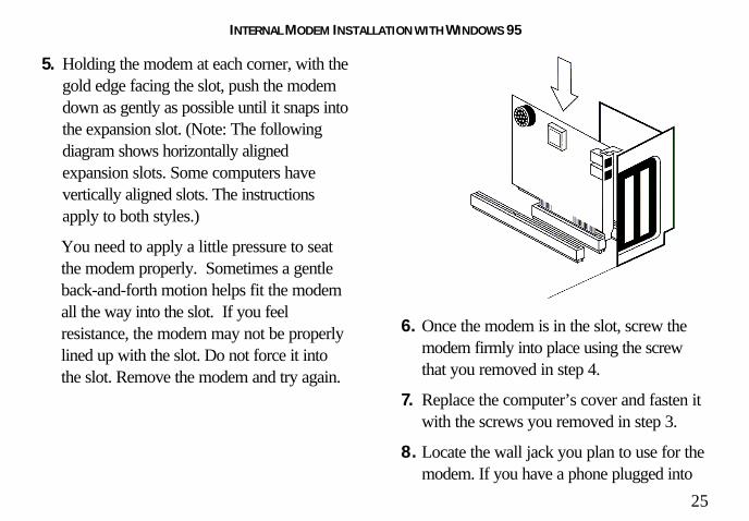
5. Holding the modem at each corner, with thegold edge facing the slot, push the modemdown as gently as possible until it snaps intothe expansion slot. (Note: The followingdiagram shows horizontally alignedexpansion slots. Some computers havevertically aligned slots. The instructionsapply to both styles.)
You need to apply a little pressure to seatthe modem properly. Sometimes a gentleback-and-forth motion helps fit the modemall the way into the slot. If you feelresistance, the modem may not be properlylined up with the slot. Do not force it intothe slot. Remove the modem and try again.
6. Once the modem is in the slot, screw themodem firmly into place using the screwthat you removed in step 4.
7. Replace the computer’s cover and fasten itwith the screws you removed in step 3.
8. Locate the wall jack you plan to use for themodem. If you have a phone plugged into

INTERNAL MODEM INSTALLATION WITH WINDOWS 95
26
this jack, disconnect the phone’s cord fromthe jack.
WARNING : The phone jack youuse must be for an ANALOG phone line(the type found in most homes). Manyoffice buildings have digital phonelines. Be sure you know which type ofline you have. The modem will bedamaged if you use a digital phone line.
9. Plug one end of the phone cord includedwith the modem into the TELCO jack atthe rear of the modem. Plug the other endof the cable into the wall jack.
10. If you wish to use a phone through the linethe modem uses (when the modem is not inuse), plug your phone’s cord into themodem’s PHONE jack.
NOTE: You cannot use the modemand a phone at the same time if theyshare the same telephone line.
11. Plug the power cords, cables, andperipherals back into the computer and turnthe computer on.

INTERNAL MODEM INSTALLATION WITH WINDOWS 95
27
Installing the ModemDrivers
NOTE: If you wrote “950b” onpage 2 of this User’s Guide, got to“Installing Modem Drivers withWindows 95 Version 950b” on page 29.Otherwise, follow these instructions.
Installing Modem Drivers withWindows 95 Versions 950 and 950a
1. When Windows 95 restarts, it shoulddetect the modem. If it does, you will seethe following screen.
Click Driver from disk provided byhardware manufacturer. Then click OK.
NOTE: If this screen does notappear, go to the section titled “ManualModem Installation” on page 49.

INTERNAL MODEM INSTALLATION WITH WINDOWS 95
28
2. When you see this screen, insert theConnections CD into your CD-ROMdrive and type D:\ to replace the A:\.(NOTE: If your CD-ROM drive has adifferent letter name, type that letter insteadof D.)
Click OK. Windows will load the modem’sdrivers.
3. Once Windows finishes loading theinformation from the CD-ROM, you shouldverify that the modem installation was asuccess. When your desktop returns, clickthe Windows Start button and point toSettings. Then click Control Panel.

INTERNAL MODEM INSTALLATION WITH WINDOWS 95
29
4. Double-click the Modems icon (circled inthe screen image below).
5. In the “Modems Properties” screen, youshould see “Sportster 33600 Fax PC Plugand Play” listed.

INTERNAL MODEM INSTALLATION WITH WINDOWS 95
30
This means the installation was a success.Click OK.
NOTE: If you do not see yourmodem listed in the precedingscreen, the Plug and Play installationwas unsuccessful. Please refer to the“Manual Modem Installation”section on page 49.
6. Next, click the Diagnostics tab at the topof the “Modems Properties” screen. Writedown the COM setting for your modem.(NOTE: Your screen may show a differentsetting than that shown in the followingscreen.) You will need to know this settingwhen you install RapidComm.
Turn to “Software Installation and Testing”(page 57) for detailed information aboutinstalling RapidComm, registering themodem, and trying out your modem byfaxing U.S. Robotics.

INTERNAL MODEM INSTALLATION WITH WINDOWS 95
31
Installing Modem Drivers withWindows 95 Version 950b
1. When Windows restarts, it should detectthe modem (see following screen image).Insert the Connections CD and clickNext.
NOTE: If this screen does notappear, go to the section titled “ManualModem Installation” on page 49.
2. When you see the following screen, clickFinish.

INTERNAL MODEM INSTALLATION WITH WINDOWS 95
32
3. Once Windows 95 has installed themodem’s drivers, you will see the followingscreen. This screen tells you whichcommunications port your modem isinstalled to. (NOTE: Your screen mayshow a different COM port.) Make a noteof the COM port setting. You will need thisinformation later when you installing thesoftware on the CD-ROM. Remove theCD from your CD-ROM drive and clickOK. Windows will restart.
4. Once Windows restarts, you should verifythat the modem installation was a success.When your desktop returns, click theWindows Start button and point toSettings. Then click Control Panel.

INTERNAL MODEM INSTALLATION WITH WINDOWS 95
33
5. Double-click the Modems icon (circled inthe screen image below).
6. In the “Modems Properties” screen, youshould see “Sportster 33600 Fax PC Plugand Play” listed.

INTERNAL MODEM INSTALLATION WITH WINDOWS 95
34
This means the installation was a success.Click OK.
NOTE: If you do not see yourmodem listed in the precedingscreen, the Plug and Play installationwas unsuccessful. Please refer to the“Manual Modem Installation”section on page 49.
7. Next, click the Diagnostics tab at the topof the “Modems Properties” screen. Writedown the COM setting for your modem.(NOTE: Your screen may show a differentsetting than that shown in the followingscreen.) You will need to know this settingwhen you install RapidComm.
Turn to “Software Installation and Testing”(page 57) for detailed information aboutinstalling RapidComm, registering themodem, and trying out your modem byfaxing U.S. Robotics.

EXTERNAL MODEM INSTALLATION WITH WINDOWS®
3.X
35
You’ll need these items from yourSportster ® modem box:
modem phone cord
Connections™ CD power adapter
Plus:
Serial modem cable. (Not included. See nextcolumn.)
How to Determine WhichSerial Cable to BuyBefore you can begin installation, you need topurchase an RS-232 serial modem cable. Thissection will help you to determine which serialmodem cable to purchase.
NOTE: Your computer’s rear panelmay not be identical to the followingdiagrams. However, you should look forconnectors that match the enlargedportions of the diagrams. If you cannotlocate the proper connector, refer toyour computer’s manual.

EXTERNAL MODEM INSTALLATION WITH WINDOWS 3.X
36
If your PC's serial connector looks like this…
you need a shielded serial modem cable with a25-pin female to 25-pin male connector.
If your PC's serial connector looks like this…
you need a shielded serial modem cable with a9-pin female to 25-pin male connector.
How to Connect the Modemto the Computer1. Turn off your computer and any attached
devices, such as a printer.
2. Connect the serial cable to the modem andto the computer. When looking for theserial port label on the back of yourcomputer, look for ports labeled COM,MODEM, RS-232, or SERIAL. DONOT select AUX, GAME, LPT, orPARALLEL.
3. Plug the power adapter into the a standardwall outlet and insert its plug into the powerjack on the modem (labeled with a poweradapter icon on the bottom of the case).

EXTERNAL MODEM INSTALLATION WITH WINDOWS 3.X
37
4. Plug one end of the phone cord into theTELCO jack (labeled with a wall plug iconon the bottom of the case) and the otherend into a phone wall jack.
WARNING : The phone jack youuse must be for an ANALOG phone line(the type found in most homes). Manyoffice buildings have digital phonelines. Be sure you know which type ofline you have. The modem will bedamaged if you use a digital phone line.
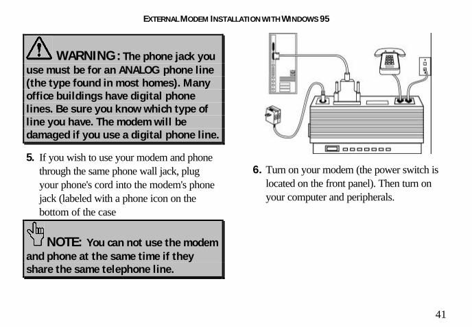
5. If you wish to use your modem and phonethrough the same phone wall jack, plugyour phone's cord into the modem's phonejack (labeled with a phone icon on thebottom of the case).
NOTE: You cannot use the modemand a phone at the same time if theyshare the same telephone line.
6. Turn your modem on. Then turn yourcomputer on.

EXTERNAL MODEM INSTALLATION WITH WINDOWS 3.X
38
You are now ready to install the softwareon the Connections CD-ROM (includedwith your Sportster modem). Turn to“Software Installation and Testing” (page57) for detailed information about installing
the software, registering the modem, andtrying out your modem by faxing U.S.Robotics.

EXTERNAL MODEM INSTALLATION WITH WINDOWS®
95
39
You’ll need these items from yourSportster ® modem box:
modem phone cord
Connections™ CD power adapter
Plus:
Serial modem cable. (Not included. See nextcolumn.)
How to Determine WhichSerial Cable to BuyBefore you can begin installation, you need topurchase an RS-232 serial modem cable. Thissection will help you to determine which serialmodem cable to purchase.
NOTE: Your computer’s rear panelmay not be identical to the followingdiagrams. However, you should look forconnectors that match the enlargedportions of the diagrams. If you cannotlocate the proper connector, refer toyour computer’s manual.

EXTERNAL MODEM INSTALLATION WITH WINDOWS 95
40
If your PC's serial connector looks like this…
you need a shielded serial modem cable with a25-pin female to 25-pin male connector.
If your PC's serial connector looks like this…
you need a shielded serial modem cable with a9-pin female to 25-pin male connector.
How to Connect the Modemto the Computer
1. Turn off your computer and any attacheddevices, such as a printer.
2. Connect the serial cable to the modem andto the computer. When looking for theserial port on the back of your computer,look for labels marked COM, MODEM,RS-232, or SERIAL. DO NOT selectAUX, GAME, LPT, or PARALLEL.
3. Plug the power adapter into a standard walloutlet and insert its plug into the power jackon the modem (labeled with a poweradapter icon on the bottom of the case).
4. Plug one end of the phone cord into theTELCO jack (labeled with a wall plug iconon the bottom of the case) and the otherend into a phone wall jack.
EXTERNAL MODEM INSTALLATION WITH WINDOWS 95
41
WARNING : The phone jack youuse must be for an ANALOG phone line(the type found in most homes). Manyoffice buildings have digital phonelines. Be sure you know which type ofline you have. The modem will bedamaged if you use a digital phone line.
5. If you wish to use your modem and phonethrough the same phone wall jack, plugyour phone's cord into the modem's phonejack (labeled with a phone icon on thebottom of the case
NOTE: You can not use the modemand phone at the same time if theyshare the same telephone line.
6. Turn on your modem (the power switch islocated on the front panel). Then turn onyour computer and peripherals.

EXTERNAL MODEM INSTALLATION WITH WINDOWS 95
42
Installing the ModemDrivers
NOTE: If you wrote “950b” onpage 2 of this User’s Guide, go to“Installing Modem Drivers withWindows 95 Version 950b” on page 44.Otherwise, follow these instructions.
Installing Modem Drivers withWindows 95 Versions 950 and 950a
1. When Windows 95 restarts, it shoulddetect the modem. If it does, you will seethe following screen.
Click Driver from disk provided byhardware manufacturer. Then click OK.

EXTERNAL MODEM INSTALLATION WITH WINDOWS 95
43
2. When you see this screen, insert theConnections CD into your CD-ROMdrive and type D:\ to replace the A:\.(NOTE: If your CD-ROM drive has adifferent letter name, type that letter insteadof D.)
Click OK. Windows will load the modem’sdrivers.
3. Once Windows 95 finishes loading theinformation from the CD-ROM, you shouldverify that the modem installation was asuccess. When your desktop returns, clickthe Windows Start button and point toSettings. Then click Control Panel.

EXTERNAL MODEM INSTALLATION WITH WINDOWS 95
44
4. Double-click the Modems icon (circled inthe screen image below).
5. In the “Modems Properties” screen, youshould see “Sportster 33600 Fax Plug andPlay” listed.
This means the installation was a success.Click OK.

EXTERNAL MODEM INSTALLATION WITH WINDOWS 95
45
NOTE: If you do not see yourmodem listed in the precedingscreen, the Plug and Play installationwas unsuccessful. Please refer to the“Manual Modem Installation”section on page 49.
6. Next, click the Diagnostics tab at the topof the “Modems Properties” screen. Writedown the COM setting for your modem.(NOTE: Your screen may show a differentsetting than that shown in the followingscreen.) You will need to know this settingwhen you install RapidComm later. Turn to “Software Installation and Testing”
(page 57) for detailed information aboutinstalling RapidComm, registering themodem, and trying out your modem byfaxing U.S. Robotics.

EXTERNAL MODEM INSTALLATION WITH WINDOWS 95
46
Installing Modem Drivers withWindows 95 Version 950b
1. When Windows restarts, it should detectthe modem (see following screen image).Insert the Connections CD and clickNext.
NOTE: If this screen does notappear, go to the section titled “ManualModem Installation” on page 49.
2. When you see the following screen, clickFinish.

EXTERNAL MODEM INSTALLATION WITH WINDOWS 95
47
3. Once Windows 95 has installed themodem’s drivers, you will see the followingscreen. This screen tells you whichcommunications port your modem isinstalled to. (NOTE: Your screen mayshow a different COM port.) Make a noteof the COM port setting. You will need thisinformation later when you installing thesoftware on the CD-ROM. Remove theCD from your CD-ROM drive and clickOK. Windows will restart.
4. Once Windows restarts, you should verifythat the modem installation was a success.When your desktop returns, click theWindows Start button and point toSettings. Then click Control Panel.

EXTERNAL MODEM INSTALLATION WITH WINDOWS 95
48
5. Double-click the Modems icon (circled inthe screen image below).
6. In the “Modems Properties” screen, youshould see “Sportster 33600 Fax Plug andPlay” listed.
This means the installation was a success.Click OK.

EXTERNAL MODEM INSTALLATION WITH WINDOWS 95
49
NOTE: If you do not see yourmodem listed in the precedingscreen, the Plug and Play installationwas unsuccessful. Please refer to the“Manual Modem Installation”section on page 49.
7. Next, click the Diagnostics tab at the topof the “Modems Properties” screen. Writedown the COM setting for your modem.(NOTE: Your screen may show a differentsetting than that shown in the followingscreen.) You will need to know this settingwhen you install RapidComm. Turn to “Software Installation and Testing”
(page 57) for detailed information aboutinstalling RapidComm, registering themodem, and trying out your modem byfaxing U.S. Robotics.

MANUAL MODEM INSTALLATION
50
Plug and Play installations are not alwayssuccessful. If you were directed to this section,Plug and Play installation failed to workproperly. Follow these instructions to manuallyinstall your new Sportster modem:
1. From the Windows 95 desktop,double-click My Computer.
2. Double-click Control Panel.
2. Double-click Add New Hardware.
4. Click Next.

MANUAL MODEM INSTALLATION
51
5. Click No and then click Next. 6. Click Modem and then click Next.

MANUAL MODEM INSTALLATION
52
7. When you see this screen, de-select theDon’t detect my modem… option if it’sselected (i.e. make sure there is not a checkmark in the box next to the selection). Thenclick Next.
8. Click Change.

MANUAL MODEM INSTALLATION
53
9. Click Have Disk. 10. When you see this screen, insert theConnections CD into your CD-ROMdrive. Type D:\ in the Copymanufacturer’s files from: field.. Thenclick OK.
NOTE: If your CD drive has a lettername other than “D”, type that letter inplace of “D”.

MANUAL MODEM INSTALLATION
54
11. When you see this screen, click U.S.Robotics, Inc. in the first column andthen click Sportster 33600 Fax PCPlug and Play (in the second column)if you installed an internal modem orSportster 33600 Fax Plug and Playif you installed an external modem.Then click OK.
NOTE: The following screen shows aninternal 33.6 modem being selected.
12. Write the COM port setting (in the top lineof the following screen) here: ____.(NOTE: The following screen showsinformation for an internal modem installedon COM 4. Your screen may showdifferent information.)
Click Next.

MANUAL MODEM INSTALLATION
55
13. When you see this screen, click Finish. 14. Now you should verify that the modeminstallation was a success. When yourdesktop returns, click the Windows Startbutton and point to Settings. Then clickControl Panel.

MANUAL MODEM INSTALLATION
56
15. Double-click the Modems icon (circled inthe screen image below).
16. In the “Modems Properties” screen, youshould see your modem listed.
NOTE: The screen below shows anexternal 33.6 modem listed. Your screenmay show different information, but youshould verify that the description is accuratefor the product you installed.

MANUAL MODEM INSTALLATION
57
This means the installation was a success.Click OK.
NOTE: If you do not see yourmodem listed in the precedingscreen, the installation wasunsuccessful. Please refer to the“Troubleshooting and Online HelpResources” section on page 113.
Turn to “Software Installation and Testing”(page 57) for detailed information aboutinstalling RapidComm, registering themodem, and trying out your modem byfaxing U.S. Robotics.

SOFTWARE INSTALLATION AND TESTING
58
Software Installation andRegistration Using theSetup WizardThis section guides you through the U.S.Robotics Setup Wizard, the Connections™
CD-ROM interface, and the installation ofRapidComm™ fax/data software. It also showsyou how to register and test your newSportster modem.
RapidComm fax/data software simplifiessending and receiving faxes directly from yourcomputer desktop. You can build your ownfax directory, send faxes to specified groups ofphone numbers, request individual cover pageswhen necessary, and send individual faxeswithout exiting your word processing program.
Additionally, RapidComm software lets youconnect to BBSs and other online dataproviders. Take advantage of this access toenter a new world of information andentertainment.
NOTE: The following instructionsapply to Windows 3.x and Windows 95users. However, only Windows 95screens are shown.
NOTE: If you have an olderversion of RapidComm softwareinstalled on your system, uninstall itbefore continuing.

SOFTWARE INSTALLATION AND TESTING
59
1. From the Windows 95 desktop, click theStart button and then click Run.
2. In the text box, type D:\setup.exe. (If yourCD-ROM drive has a letter name otherthan D, type that letter in place of D.)
3. You will briefly see a screen that looks likethis.
4. When you are asked if you wish to run theSetup Wizard, click Yes.

SOFTWARE INSTALLATION AND TESTING
60
5. This is the Setup Wizard’s “Welcome”screen. After reading the screen, clickNext.
6. When you see the following screen, selectyour modem from the list, verify that theCOM port setting is correct, and then clickNext.
NOTE: Check the COM portsetting against the setting you wrotedown during the hardware installation.

SOFTWARE INSTALLATION AND TESTING
61
7. When you see the next two screens, fill inthe blank boxes with the appropriateinformation, using the TAB key to movebetween fields. Click Next on each screenwhen you have filled in all of the necessaryinformation.

SOFTWARE INSTALLATION AND TESTING
62
8. You will see the following screen as theSetup Wizard creates a U.S. RoboticsConnections program group.
9. Next, the Setup Wizard looks for NetscapeNavigator on your system.
If the Setup Wizard does not find NetscapeNavigator, it searches for Microsoft’sInternet Explorer. If the Setup Wizard doesnot find Internet Explorer, it willautomatically install the application later inthe Setup Wizard process.
10. The next screen introduces the U.S.Robotics Registration Wizard. After youread the screen, click Next. Read througheach of the next two screens and verify orcorrect the information you typed earlier.Click Next on each screen to move on.

SOFTWARE INSTALLATION AND TESTING
63
11. When you see this screen, you are ready toregister your new modem. Click ByModem. We recommend you choose theBy Modem option because it’s a greatway to verify that your Sportster modem iscorrectly installed.
SOFTWARE INSTALLATION AND TESTING
64
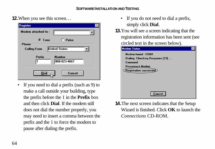
12. When you see this screen…
• If you need to dial a prefix (such as 9) tomake a call outside your building, typethe prefix before the 1 in the Prefix boxand then click Dial. If the modem stilldoes not dial the number properly, youmay need to insert a comma between theprefix and the 1 to force the modem topause after dialing the prefix.
• If you do not need to dial a prefix,simply click Dial.
13. You will see a screen indicating that theregistration information has been sent (seecircled text in the screen below).
14. The next screen indicates that the SetupWizard is finished. Click OK to launch theConnections CD-ROM.

SOFTWARE INSTALLATION AND TESTING
65
NOTE: If the Setup Wizard detectedInternet Explorer on your system during thesetup process, your computer will launchthe Connections CD-ROM when you clickOK. Continue at step 15.
If the Setup Wizard DID NOT detectInternet Explorer on your system earlier inthe setup process, it will launch the InternetExplorer installation utility after you clickOK. When you see the following screen,click Install Internet Explorer and followthe on-screen instructions to complete theinstallation of the software.
At the end of the installation process, youwill see the following screen. Click Yes.
Windows 95 users: Windows will restartand the Connections CD will launchautomatically upon restart.

SOFTWARE INSTALLATION AND TESTING
66
Windows 3.x users: Windows willrestart. When your desktop reappears, youwill see a Connections icon (shown below)in the Connections program group.Double-click the icon to launch the CD.
15. When the main Connections menuappears, click Business & Productivityon the left hand side of the screen (circledbelow).

SOFTWARE INSTALLATION AND TESTING
67
16. On the Business & Productivity menu isa RapidComm button (circled in thefollowing screen shot). RapidComm is thefax/data software you can use to send faxesdirectly from your desktop, transfer fileselectronically, or dial into a BBS. ClickRapidComm.
17. The next screen contains a menu on theright hand side of the screen. Included onthe menu is a Learn More & GetSoftware button (circled in the screenimage below). Click this button.

SOFTWARE INSTALLATION AND TESTING
68
18. The next screen displays information aboutthe RapidComm software. When you areready to install the RapidComm software,click Install (circled in the lower left handcorner of the following screen image).
NOTE: If you are using NetscapeNavigator to view your Connections CD-ROM, you may be asked to save theapplication’s installer to your computerwhen you click the Install button. Notethe installer’s file name and its locationon your computer. To run the installeror demo, find the file on your computerand double-click it. The installer willstart.

SOFTWARE INSTALLATION AND TESTING
69
19. The next screen is the first of the“RapidComm Setup” screens. When thisscreen appears, make sure the locationshown in the text box is where you wouldlike the files copied to and then clickInstall. If you wish to copy theRapidComm files to a different directory,type that location in the text box beforeclicking Install.
20. You will see this screen as files are copied.
21. When you see this screen, click either Yesor No.
• If you click Yes, every document youprint will be treated as a fax unless youchange the printer selection in theprogram from which you are printing.
• If you click No, RapidComm will not beselected as the default printer. When you

SOFTWARE INSTALLATION AND TESTING
70
want to send a fax, you must selectRapidComm as the printer in theprogram from which you are printing.
22. This screen marks the end of the
RapidComm installation. Click OK.
23. Click OK to return to Connections. ClickExit (circled in the following screen image).

SOFTWARE INSTALLATION AND TESTING
71
24. Restart Windows by clicking the WindowsStart button and pointing to Shut Down.Click Restart the Computer? on the ShutDown Windows screen. Then click Yes.
25. When your desktop appears, clickWindows Start. Point to Programs. Thenclick RapidComm.
26. The following is the first RapidCommSetup Wizard screen. After you read thescreen, click Next.

SOFTWARE INSTALLATION AND TESTING
72
27. When you see this screen, verify theinformation shown and then fill in the Databox (if you have a third phone number justfor your modem) and the Local AreaCode box. Then click Next.
28. After you verify the information on thisscreen, click Next.

SOFTWARE INSTALLATION AND TESTING
73
29. Select the correct modem in the text boxon the following screen. Then click Next.
30. When you see this screen…
• If you want the RapidComm program tolaunch with every Windows startup,select the Run RapidComm atWindows startup check box. Thenclick Finish.
• If you do not want RapidComm to startevery time you start Windows, simplyclick Finish.

SOFTWARE INSTALLATION AND TESTING
74
31. You will see this screen.
This is the main RapidComm screen. Tosend your first fax, keep this screen open.(After this initial run, RapidComm will notneed to be running in order to send a fax.)
Sending Your First FaxUsing RapidComm software, you can sendand receive faxes directly from your computerand eliminate the need for a fax machine. Onceyou learn the basics of sending faxes, you canlearn more involved fax functions, such assending documents to groups of numbers atassigned times and how to transfer data files.These more advanced functions are explainedin the electronic RapidComm manual on yourConnections CD. This chapter will walk youthrough sending your first fax.
1. Open an application in which you cancreate documents that you might want tofax (i.e. a word processing application).Create a document containing only asentence or two. Name the documenttester. Keep the document open.

SOFTWARE INSTALLATION AND TESTING
75
2. From the File menu, click Print.
3. Select RapidComm as the printer. This canbe changed in most Windows applicationsin the Print dialog box.
4. Click OK or Print (whichever button youclick in your application to indicate that youare ready to print) in the Print dialog box.
5. When you see the following screen, fill inthe necessary information in the text boxes.For testing purposes, send your “tester”
document to the 3Com fax number, 847-676-3559.
NOTE: If you need to enter aprefix (such as 9) to dial a numberoutside your building, type the prefixbefore the fax number in the Faxnumber field.
When you finish, click Send Fax.

SOFTWARE INSTALLATION AND TESTING
76
6. You will see a series of screens as the fax isbeing transmitted. When the fax has beensuccessfully transmitted, you will see ascreen that looks like this.
Congratulations —you arenow ready to start usingyour Sportster modem!
Go to the electronic RapidComm manual onyour Connections CD for more detailedinstructions on sending faxes and other thingsyou can do using your Sportster modem andRapidComm software.

INSTALLING OTHER FAX/DATA SOFTWARE
77
You do not have to use the RapidCommfax/data software included with your newSportster modem. Your modem was designedfor and tested using a wide range ofcommunications software packages. Thissection will guide you through some of thedetails you may need to know when installingother communications software packages.
Type of ModemMost communications software programs willask you to select the type of modem you areusing. Select a U.S. Robotics Sportster highspeed modem. If that selection is not listed,pick Courier Dual Standard, V.32bis, or V.34.
D KEY POINT: Refer to the manualthat came with your software for itsinstallation instructions. Thesoftware’s installation program will askyou questions about the modem you areusing.
Initialization StringFor hardware flow control, a fixed serial port rate and fullresult codes, type AT&F1 and then press ENTER.If you must use software flow control, type AT&F2 andthen press ENTER.
Flow Control• For hardware flow control (highly recommended),
select RTS/CTS
• For software flow control, select XON/XOFF.

INSTALLING OTHER FAX/DATA SOFTWARE
78
NOTE: You may need to disablethe flow control (hardware or software)that you are not using.
UART (External Modems)If you are running Windows 3.x or you haveupgraded your system from Windows 3.x toWindows 95, you can run MSD to determineyour UART setting. In DOS, type MSD at theWindows directory prompt and then pressENTER. Follow the on-screen instructions toaccess the COM port settings panel. In thisscreen you should find the UART chip used(the last item in each COM port column).Match the UART type listed in MSD with theserial rate listed in the chart below. Select this
serial rate in any communications software youuse.
Select thisIf this is your UART... serial rate
16550* 115.2 or 57.6 kbps
16450 38.4 kbps
8250 19.2 kbps
*All Sportster internal modems have a 16550 UART.
NOTE: DO NOT select a 28,800,14,400, or 12,000 bps serial port rate, ifoffered. Your modem will NOT workcorrectly with any of these settings. Fixor lock the serial port (baud) rate (ifthere is a setting referred to asautobaud, select OFF).

USING MODEM STATION
79
What Does Modem StationDo?♦ Modem Station provides a simple to use
interface that makes communicating withyour modem even easier.
♦ Modem Station allows you to point andclick your way through configuration.
♦ Modem Station can automatically detectyour modem and provide you with all thetechnical information you need, wheneveryou need it!
Why Modem Station?♦ Modem commands can be confusing and
difficult to memorize.♦ Communications software often needs
technical information about your modem.
♦ You may want to “tweak” your modem foroptimum performance.
♦ You’d rather be surfing the Internet.
Installing Modem StationIf you did not install Modem Station when youfirst installed the Connections CD, pleasefollow these instructions.
1. Insert the Connections CD into your CD-ROM drive.
2. Double-click the My Computer icon onyour desktop.
3. Double-click the CD-ROM icon.
4. Double-click the USR Tools folder.
5. Double-click the umssetup icon.

USING MODEM STATION
80
6. You will be asked whether you wish toinstall Modem Station. Click Yes.
7. Wait a few moments for the InstallationWizard to load.
8. After reading the information on the“Welcome” screen, click Next.
9. When you see this screen, click Next toaccept the default directory or clickBrowse to change directories.

USING MODEM STATION
81
10. Click Next on the following screen toaccept the default program folder. You canplace Modem Station in an existing folderby selecting one from the list.
11. When you see the following screen, clickFinish to complete the installation.
If this is the first time you’ve installedModem Station, you may be asked torestart your computer.

USING MODEM STATION
82
Starting Modem Station1. If you didn’t start Modem Station from the
Setup program, please start it now.
2. Click Windows Start button and then pointto Programs. Click U.S. RoboticsModem Station (or the folder youselected during installation).
3. Click the Modem Station icon. This bringsup the main menu.

USING MODEM STATION
83
The main menu gives you direct access tothe following options:
♦ DETECT NEW MODEMS♦ TERMINAL♦ MODEM CONFIGURATOR♦ ABOUT♦ CONTACT/SUPPORT
DETECT NEW MODEMS
This option detects US Robotics modemsinstalled on your system and shows whatCOM port they are using. Click this option ifyou are running Modem Station for the firsttime, if you are changing modems, or if yousimply need to know what port your modem isusing.
TERMINAL
Terminal allows you to send commandsdirectly to your modem and displays the
responses. You can use Terminal to dial upBBSs. In addition, you can configure yourmodem using Terminal. However, it is mucheasier to use the Modem Configurator.
MODEM CONFIGURATOR
Modem Configurator provides an easy-to-useinterface for entering hard to remembercommands. Use Modem Configurator fortroubleshooting, initial configuration, and tuningyour modem for optimum performance. Usingthe options available in Modem Configurator,you can control nearly every aspect of yourmodem’s performance. We will discussModem Configurator’s options in more detailin later sections.
ABOUT
The About option provides copyright andversion information.

USING MODEM STATION
84
CONTACT/SUPPORTThis option details how to get in touch withU.S. Robotics.
TIP: For your convenience, weprovide many on-line supportavenues. For specific questions,our fax-on-demand service is agood place to start. You candownload FAQs, software, and helpfiles from our Web sites and BBS,or receive individualized supportvia [email protected]. Type 0000 (4zeroes) in the subject line of youre-mail.
I
Using Detect New Modems1. Click Detect New Modems to bring up
the following screen.
The screen consists of four columns, one foreach possible COM port on a PC. Youcan scan a specific port(s) by selecting thecheckbox for that port.

USING MODEM STATION
85
2. Click Scan to have Modem Station checkfor installed modems. This may take a fewmoments.
3. When the scan finishes, you will see thefollowing display. Your display may differdepending on the type and number ofmodems installed.
If your modem is installed and configuredcorrectly, Modem Station will find themodem and display make and modelinformation under the assigned port. Allcurrently active ports should display “PortOK” under the heading. If a port displays a“Port Error”, it usually means that the port isdisabled in system setup.
NOTE: Different systems andBIOSes use different methods ofdisabling COM ports. As a result,we cannot provide support forenabling COM ports. Please referto your system’s documentation orcontact the manufacturer of yoursystem for further information.

USING MODEM STATION
86
If you look at the information for the port yourmodem is using, you will see three buttons.These allow you to access Terminal andModem Configurator without going back tothe main menu. Extended Information providesdetailed information about your modem,previous connections, firmware dates, etc. Thisnext section details using the Terminal option.
Using TerminalYou can access Terminal from either the Mainmenu or the Detect New Modems screen.Clicking Terminal brings up the Terminalwindow.
In addition to allowing direct entry of modemcommands, the Terminal window also allowsyou to dial into Bulletin Boards, listing services,and other online services.

USING MODEM STATION
87
NOTE: Modem Station’sTerminal window is providedprimarily for troubleshootingconvenience. If you frequently useBBSs, you will probably want touse a separate, full-featuredTerminal program like the oneprovided in our RapidCommsoftware.
On the lower part of the Terminal screen, youwill see the COM port your modem iscurrently using. To select another modem,simply click on the arrow and select thatmodem’s assigned port.
To the right of the port settings are the portspeed settings. Port speed is the speed atwhich your computer sends data to the

USING MODEM STATION
88
modem. We will discuss port speed settings indetail later in this section.
Terminal includes a basic auto dialer.
To have Terminal dial a number for you, clickDial to bring up the “Dial” screen.
You need to tell the Dialer a few things aboutyour phone system, such as whether it usestone or pulse dialing, what digit, if any, youneed to dial to get an outside line, and whetherthe dialer should wait between dialing that digitand the rest of the number. Once you providethis information, simply enter the phone numberas if you were dialing a telephone. Click DialNow to dial the number.
You can end a call by clicking Hang Up at thebottom of the screen.
When you are finished using Terminal, clickExit to return to the screen you accessed itfrom.
Using Modem ConfiguratorYou can access Modem Configurator fromeither the Main menu or the Detect NewModems screen.
Click Modem Configurator to bring up thismenu.

USING MODEM STATION
89
The Modem Configurator menu gives youaccess to the following options:
♦ DATA CONTROL♦ CONNECTION CONTROL♦ MODEM TO COMPUTER♦ CONNECTION RATES♦ DIALING/ANSWERING♦ STORED NUMBERS♦ RESTORE DEFAULTS♦ EXIT
Data Control
This is the “Data Control” screen.
The “Data Control” screen allows you toassign the following basic communicationssettings:
♦ PORT SPEED♦ PARITY♦ STOP BITS♦ WORD♦ FLOW CONTROL♦ SERIAL PORT RATE
For information on using these settings, pleaserefer to the “Glossary” at the back of thismanual.
Click Help for quick definitions of theterminology used in this screen.
In the upper left-hand corner of the screen,you will see the data control commandscurrently in use.

USING MODEM STATION
90
Once you have entered the Data Controlsettings, click Save to Modem. This storesthe settings so that you do not have to re-enterthem.
This screen also displays the default DIPswitch settings.
TECHNICAL STUFF: DIPswitches are tiny switches thatcontrol a few basic functions onsome external modems. Onmodems without DIP switches,these functions are handled bymodem commands.
Click Exit to return to the ModemConfigurator menu.
CONNECTION CONTROL
This is where you adjust your modem’sconnection and transmission settings.
Click Connection Control to bring up thisscreen.
In the upper left hand corner of this screen,you will find the current Connection Controlsettings.

USING MODEM STATION
91
Use the “Connections Control” screen toconfigure the following settings:
♦ DATA TERMINAL READY (DTR)♦ ERROR CORRECTION♦ DATA COMPRESSION♦ CARRIER DETECT
For detailed information about these settings,refer to the “Glossary” or the “Technical QuickReference” sections of this manual.
TIP: On external modems,receiving a Data Terminal Ready signalcauses the TR light to light up.
Click Help for quick definitions of terminologyused in this screen.
Once you have configured your ConnectionControl settings, click Save to Modem tosave your settings
Using Modem to ComputerThese settings control how your modem andcomputer communicate with each other. Theycontrol what you see on your terminal screenand how results are displayed.

USING MODEM STATION
92
If you look in the upper left hand corner of thedisplay, you will see the commands currently inuse.
The “Modem to Computer” screen allows youto configure the following settings:
♦ LOCAL ECHO♦ RESULT CODES♦ RESULT CODE PREFERENCES
TIP: If you type ATDT and see‘AATTDDTT’ on your screen, it ispossible that both your software andmodem have Local Echo set to ‘ON’.Turn Local Echo ‘OFF’ on EITHER themodem or the software to solve thisproblem.
For details on using the commands in thisscreen, refer to the “Glossary” or “TechnicalQuick Reference” sections of this manual.
Click Help to see quick definitions ofterminology used in this screen.
This screen also includes a chart of the waysresult codes can be displayed. Click Codes toview a chart of the display options.
Once you configure your settings, click Saveto Modem to save your choices.

USING MODEM STATION
93
CONNECTION RATES
The “Connection Rates” screen allows you toconfigure modem speeds and protocols.
WARNING! Use cautionwhen changing connectionsettings. Improper settings maycause your modem to functionincorrectly, disconnect, or fail toconnect at all.
In the upper left hand corner of the screen youwill see the current connection commands.
This screen allows you to configure thefollowing settings:
♦ MODULATIONS♦ V.34 SYMBOL RATES♦ SPEEDS
Again, once you have selected your settings,click Save to Modem to save them.
When you are finished, click Exit to return tothe Modem Configurator menu.
Please refer to the main body of the manualand the “Glossary “for detailed informationabout the terminology and settings used in thisscreen.
Click Help for quick definitions of terminologyused in this screen.

USING MODEM STATION
94
DIALING/ANSWERING
The next screen allows you to adjust how yourmodem initiates and receives calls.
Using this screen, you can configure thefollowing dial settings:
♦ WAIT FOR CARRIER♦ AUTO-ANSWER # OF RINGS♦ SPEAKER OPERATION♦ DIALING METHOD♦ SPEAKER VOLUME
TECHNICAL STUFF:“Negotiation” is the noise we hearwhen two modems connect. Themodems exchange informationabout their respective protocolsand configurations. Once theyagree on the fastest protocol theycan both handle, transmissionbegins.
STORED NUMBERS
The “Stored Numbers” screen displays thephone numbers currently stored in yourmodem’s memory.
Use this screen to edit or add numbers storedin the modem’s memory.

USING MODEM STATION
95
To store a number in your modem’s memory,simply click in one of the entry boxes. Type inthe phone number exactly as you would dial it.NOTE: Position Zero has a special feature.You can set your modem to automatically dialthis number when your computer is turned onor when it is reset.
This is very useful if you are using your modemwith a “dumb terminal” or know that you needto connect to a specific bulletin board or listingservice.
You can change stored numbers by highlightingthem and then typing the new numbers in theirplace. Once you store your numbers, you candial them by entering this command fromTerminal Mode:
ATDS0, ATDS1, ATDS2, etc.
Your U.S. Robotics modem comes with onephone number already stored in Position 0. Ifyou haven’t changed the default, typingATDS0 will automatically dial the U.S.Robotics BBS. You will want to change this ifyou are using a dumb terminal or online listingservice, of course.
Once you enter the numbers you wish to store,click Save to Modem to store them. ClickExit to return to the Main menu.
The last option, Restore Defaults, resets yourmodem to factory specifications. This option is

USING MODEM STATION
96
available from many of the screens withinModem Station. When you click RestoreDefaults, you will see a confirmation screenasking if you aresure you want to restore defaults. Click OK toproceed.
TIP: Restore Defaults will setyour modem back to factoryspecifications. It is a good place tostart when troubleshooting.
Using the ExtendedInformation ScreensThe “Extended Information” screens provideimportant and useful information about yourmodem. Unfortunately, some of thisinformation is very complex.
We devote a separate section to the ExtendedInformation screens so that we can explainwhat you’ll see (and why it is important to you)as fully as possible.
There are a series of commands used to obtaindetailed information from U.S. Roboticsmodems. Extended Information provides aconvenient way to get that importantinformation without memorizing the commands.
From the “Detect New Modems” screen, clickExtended Information.
The “Extended Information” screen providesaccess to the following information about yourmodem:
♦ ROM CHECKSUM♦ PRODUCT♦ ACTIVE PROFILE♦ STORED PROFILE

USING MODEM STATION
97
♦ CONFIGURATION PROFILE♦ LINK DIAGNOSTICS♦ VxD CONFIGURATION♦ DIAL/SECURITY
Winmodem users will have access to VxDinformation via these screens.
Courier users will have access to Dial/Securityinformation.
Click ROM Checksum to bring up thefollowing screen. Technicians use the ROM Checksum to verify
information stored in the modem’s Read OnlyMemory. You can check the ROM Checksumfrom any Terminal program by typing ATI1and pressing ENTER. For information aboutthe specific modem you are using, clickProduct to bring up the next screen.

USING MODEM STATION
98
The “Product” screen displays the make andmodel of your modem. It is the equivalent ofthe ATI3 command.
Your modem is able to store twoconfigurations or “profiles.” Only one can beactive at any time.
To see information about the profile in use,click Active Profile to bring up the nextscreen.
This screen contains information about yourmodem’s current configuration. Starting fromthe top, you will see the make and model ofyour modem. Directly below that you will seebasic commands currently in use. Below thatare the current connection settings.

USING MODEM STATION
99
The two lines below the connection settings arethe advanced commands currently in use.Below them is a display of the contents of the‘S-Registers’ for your modem. These registersare special programmable areas of yourmodem’s memory. They are used to storecommands that are too complex to be handledby the standard (or ‘AT’) commands.
Just below that you will see the last numberdialed. You can also see this information bytyping ATI4 in a Terminal program andpressing ENTER.
The next option displays the “Stored Profile”screen. This screen shows the configurationstored in your modem’s NVRAM (specialprogrammable memory). Note that any storedphone numbers are displayed on this screen aswell. This is the equivalent of the ATI5command. The information displayed is in the
same format as the “Active Profile” screen withthe addition of stored phone numbers.
The next two screens contain information thatour technical support representatives may needif you request support.
Click Configuration to bring up the first ofthese screens.

USING MODEM STATION
100
The “Configuration” screen displays thefollowing information about your modem.• Product Type displays the information
relating to the make and model of yourmodem.
• Options displays the protocols available toyour modem.
• Fax Options displays your faxcompatibility.
• Clock Frequency displays the speed of thetiny “clock” that controls the timing ofoperations within the modem.
• EPROM displays how much informationcan be stored in the EPROM (orSupervisor) chip.
• RAM displays how much memory yourmodem has for processing commands andinternal functions.
• Supervisor Date (or EPROM Date)displays the version date of the ‘firmware’
stored in the Supervisor chip. (TheSupervisor chip contains the specialsoftware used to control your modem’sfunctions.) If a support representative asksyou for your Supervisor or EPROM date,look here.
• DSP Date is the date of the ‘firmware’ thatcontrols the DSP in your modem.
• Supervisor and DSP rev (or revisions) arethe equivalent of software version numbers.
TECHNICAL STUFF: TheSupervisor chip contains the commandsthat control your modem. The DSPcontrols execution of those commands.The Supervisor chip needs orders fromthe DSP before it can carry out acommand.

USING MODEM STATION
101
• DAA Country displays the countries yourmodem is designed for. This is importantbecause phone systems andtelecommunications laws vary from countryto country.
Click Link Diagnostics to bring up the “LinkDiagnostics” screen.
The “Link Diagnostics” screen displaysstatistics about your last connection. Thisscreen is most often used as an aid indiagnosing connection failures, but it also canprovide information about connection speedsand phone line conditions.• Modulation displays the speed and type of
connection.• Carrier Frequency displays the electrical
frequency of the carrier signal.• Symbol Rate displays the speed of the
transmission.• Trellis Code, Nonlinear Encoding,
Shaping, and Precoding all refer tomethods of handling high speed datatransmission.
• The items followed by (dB), (-dB), (-dBm),and (msec) refer to variations in themodulation tones that actually carry theinformation.

USING MODEM STATION
102
The rest of the screen contains informationabout CRC errors, Block Errors (Blers),resent data, and other data. This information isvery important if you experience problemstransmitting or receiving data or if you suspectproblems with your phone service.
Only our U.S. Robotics Winmodem™
faxmodems use VxDs, or Virtual DeviceDrivers. The Winmodem product uses specialsoftware (called a ‘driver’) to manage many of
the functions handled by hardware in our othermodems. If you are using a Winmodem, theExtended Information menu will offer you theoption of clicking on VxD to view informationon the Winmodem driver. Please refer to yourWinmodem manual for detailed information onthe Winmodem drivers.Courier modem users will see a display ofcurrent Dialback/Security settings. Refer to
your Courier documentation for instructions onconfiguring these special features.
We hope that you enjoy exploring the world ofinformation and entertainment your newSportster modem will open up for you and thatModem Station will make using andconfiguring your new modem as simple aspossible.
Remember: If you have any questions orproblems, feel free to visit one of our manyonline forums.For answers to specific questions, be sure tovisit our World Wide Web support site atwww.usr.com/home/online/main.htm, or tryour BBS (847-982-5092).

U.S. ROBOTICS MODEM UPDATE WIZARD
103
Your Connections™ CD-ROM includes the U.S.Robotics Modem Update Wizard. This softwareis designed to quickly update your modem,whether to a newer version of its current code orto 3Com’s revolutionary new x2™ technology.You can update your modem in any of thefollowing 3 ways:
33.6 K to 33.6 K (update) = FREE33.6 K to 56 K (upgrade) = $FEE*
56 K to 56 K (update) = FREE* Fee for upgrades is subject to change.
NOTE: You can obtain this softwarefrom our BBS (847-982-5092) or from ourWorld Wide Web page (www.3com.com) ifyou do not have a Connections CD-ROM.
NOTE: Complete the instructions inthe Software Installation and Testingsection of this manual before installingthe Modem Update Wizard.
NOTE: These instructions pertain toWindows 3.x and Windows 95. However,only Windows 95 screen shots are shownunless the process for Windows 3.x usersdiffer significantly.
Installation1. Insert the Connections CD-ROM into your
CD-ROM drive.

U.S. ROBOTICS MODEM UPDATE WIZARD
104
2. Click the Windows Start menu and point toPrograms. Point to U.S. RoboticsConnections. Then click Connections.
NOTE: Windows 3.x users launch theCD-ROM by clicking the Connections iconin the Connections program group.
3. From the main Connections menu, clickCustomer Support (circled in the followingscreen shot).

U.S. ROBOTICS MODEM UPDATE WIZARD
105
4. When the Customer Support menu appears,click Modem Update Wizard (circled in thefollowing screen shot).
5. Next, click Learn More & Get Software(circled in the following screen shot).

U.S. ROBOTICS MODEM UPDATE WIZARD
106
6. In the following screen, click Install.
NOTE: If you use Netscape to viewthe Connections interface, you will beasked to save the setup program for theUpdate Wizard to your hard drive. Savethe utility to your hard drive and exitConnections. Run the utility to begininstallation. Then return to this page.
7. This launches the U.S. Robotics ModemUpdate Wizard Installer. The screen thatfollows is the welcome screen for the installer.After you read this screen, click Next.

U.S. ROBOTICS MODEM UPDATE WIZARD
107
8. The next screen indicates where the installerwill store the files for the Update Wizard. If theindicated location is acceptable, click Next.Otherwise, click Browse to find an acceptabledirectory.

U.S. ROBOTICS MODEM UPDATE WIZARD
108
9. You will see the following screen for a momentas the installer creates the Modem UpdateWizard program group.
10. This screen indicates that the setup iscomplete. Click OK.
Operation1. Click the Windows Start button. Point to
Programs. Then point to U.S. RoboticsModem Update Wizard. Finally, clickModem Update Wizard.
2. After you read the “Welcome” screen, clickNext.

U.S. ROBOTICS MODEM UPDATE WIZARD
109
3. This brings up the license agreement. Afterreading the license agreement, click Accept tocontinue.
4. The software will now detect any modemsinstalled on your system. When the detectionphase finishes, you will see the following screen(the modems shown on your screen maydiffer). Click the modem you wish to upgradeand then click Next to continue.

U.S. ROBOTICS MODEM UPDATE WIZARD
110
5. The program will now determine if the selectedmodem is software upgradable.
Non-Upgradable Modems
If your modem IS NOT software upgradable,the program will display the following screen.
• Click U.S. Robotics if your modem is aU.S. Robotics modem to learn more aboutyour upgrade options.
• Click Other to learn more about how topurchase a U.S. Robotics x2 modem.
Upgradable Modems
If the modem IS software upgradable, you willsee the following screen.
Click Dial U.S. Robotics (which should bethe default selection) in the pull-down menu.Click Upgrade to x2 Technology if you wish

U.S. ROBOTICS MODEM UPDATE WIZARD
111
to upgrade a 33.6 kbps modem to 56 kbpscode or click Update my modem’s code toupdate your modem with the most recentversion of its original code. Then click Next.
6. The next screen you will see is the orderinformation screen. Users who are purchasinga 56K upgrade will see a screen that includes acredit card information query. Users who areupdating their modem’s code will see apersonal information query screen. Fill in thescreen with the appropriate information andthen click Next.
7. The following screen dials the U.S. RoboticsUpdate Server. Click Tone or Pulse dialing asnecessary. If you normally dial a prefix (suchas 9) to dial out on your phone line, type thatprefix before the 1 in the Prefix box. Thenclick Dial.
NOTE: Your screen may show adifferent number in the Number field.

U.S. ROBOTICS MODEM UPDATE WIZARD
112
8. Once connected, the server will compareavailable upgrades with the current code inyour modem. If they differ, the server willautomatically initiate the download procedure.
NOTE: Users purchasing a 56Kupgrade are asked if the charge isacceptable (see the following screenimage). Unless you have already beencharged for an upgrade, click Yes tocontinue. If you have already been throughthis process once before, DO NOT clickYes . Click No and call Customer Supportat 847-982-5151. (The price of the upgradeis subject to change and includesapplicable taxes.)

U.S. ROBOTICS MODEM UPDATE WIZARD
113
NOTE: If you do not have the most upto date .inf file for your modem (the filethat helps Windows correctly identify yourmodem), you will see the following screenas the Modem Update Wizardautomatically downloads the file.

U.S. ROBOTICS MODEM UPDATE WIZARD
114
9. You will see this screen as the Wizarddownloads the file for your modem.
10. When the download is complete, the modemdisconnects from the server. The words“Downloading file…” change to “Upgrading…” or “Updating …”, depending on whetheryou are upgrading or updating your modem. Anew progress bar appears. This indicates thatyour modem’s code is being updated.
WARNING! To avoid the risk ofdamaging your modem, DO NOT turn offthe modem while it is being updated.
11. When updating is complete, the progress barwill be full and an “Update/UpgradeComplete” message appears. Click Next.

U.S. ROBOTICS MODEM UPDATE WIZARD
115
12. You will see a “Congratulations!” screen.Click Details.
13. Click OK once you verify that the process wasa success. When you return to the“Congratulations!” screen, click Finished.
Congratulations!Enjoy the benefits of your updated Sportstermodem!

TROUBLESHOOTING AND ONLINE HELP RESOURCES
113
PROBLEM DIAGNOSIS POSSIBLE SOLUTION
The computeror softwarewill notrecognize themodem.
Your modemmight not beturned on.
You may not beentering modemcommands in theproper manner.
If you are usingan externalmodem, the COMport may not beenabled.
You may have aCOM port/IRQconflict.
Make sure the modem is turned on. The power switch is on top of external modems.The CS light on the front panel should be lit. If you installed an internal modem, itshould power up when the computer is turned on.
Type in all upper case (AT) or lower case (at).
Refer to your computer’s manual for information concerning enabling COM ports(usually involves altering the bios settings, motherboard jumpers, and the operatingsystem).
WINDOWS 95 USERS: Uninstall the modem from your computer. In Device Manager,determine what COM port and IRQ settings are free on your system. Set the jumpershunts on your modem’s jumper pins to these free settings, using the diagrams below as aguide. If no IRQ setting is available, you may need to move a device off of an IRQ inorder to free it for use by your modem.
0 1 SEL COM 1
0 1 SEL COM 3
0 1 SELCOM 4
0 1 SELCOM 2
IRQ2 3 4 5 7

TROUBLESHOOTING AND ONLINE HELP RESOURCES
117
PROBLEM DIAGNOSIS POSSIBLE SOLUTION
The computer orsoftware will notrecognize themodem (cont.).
The modemdisplays doublecharacters on yourmonitor.
The modem won’tgo off hook to dialor doesn’t answerthe phone.
You may have a COMport/IRQ conflict (cont.).
Both the modem’s andsoftware’s local characterechoes are probablyturned on.
You may have pluggedyour modem’s phone cordinto a digital line.
You might have a badphone cord connection toyour modem.
You may have devicesbetween the modem andthe phone jack.
You may have a poor lineconnection.
Make sure you have the correct COM port and IRQ settings in yoursoftware and/or in the Windows Device Manager.
Disable Local Echo in your software OR on your modem (not both). Youcan turn the local echo off on the modem by typing ATE0 and thenpressing ENTER in your software’s terminal mode. To turn the local echooff in the software, refer to its documentation.
Plugging your modem’s phone cord into a digital phone line can damagethe modem. Call your phone company if you are unsure whether or notyour phone line is digital.
The phone cord should be plugged into the TELCO jack on the modemand the wall phone jack. The phone cord should be no longer than 12 feetin length. Use the phone cord included in your Sportster box if possible.
There should be no line splitters, fax machines, or other devices betweenthe modem and the wall jack.
Place the call again. Calls are routed differently each time. To verify avalid phone connection, enter RapidComm’s Terminal mode, typeATX3DT8479855092 (the 3Com BBS), and press ENTER. This stringbypasses the dial tone, allowing a connection if the modem is functioningproperly.

TROUBLESHOOTING AND ONLINE HELP RESOURCES
118
PROBLEM DIAGNOSIS POSSIBLE SOLUTIONThe modem won’tgo off hook to dialor doesn’t answerthe phone (cont.)
Both modemsexchange carriersignals but fail toestablish a link.
Your 33.6 kbpsmodem cannotachieve a 33.6 kbpsInternet connection.
If you have voice mail,your dial tone may bealtered when messages arewaiting.
Your software may nothave auto answer enabled.
You may have a poor lineconnection.
There may be line splittersor other devices betweenyour modem and thephone jack.
The phone line you arecurrently using may not beclean enough to achieve a33.6 kbps connection.
Answer your voice mail to restore your normal dial tone.
Enable the auto answer feature. In RapidComm’s Terminal mode,type ATS0=1 and press ENTER. NOTE: You need to enable autoanswer before every session unless you alter your software’sinitialization string to permanently enable auto answer.
Try placing the call again. The phone company routes callsdifferently each time. To verify a valid phone connection, enterRapidComm’s Terminal mode and type ATX3DT8479855092 andpress ENTER (the phone number is the 3Com BBS). This stringbypasses the dial tone, allowing a connection if the modem isfunctioning properly.
Remove all devices between the modem and the phone jack it is using.Make sure the phone cord you are using is no longer than 12 feet inlength. Use the phone cord included with your Sportster if possible.
Try using a different phone line. Make sure the phone line you areusing is an analog phone line. Using a digital phone line will damageyour modem.

TROUBLESHOOTING AND ONLINE HELP RESOURCES
119
PROBLEM DIAGNOSIS POSSIBLE SOLUTIONYour modem won’tconnect at 2400bps with a 2400bps modem.
Your screen keepsdisplaying randomgarbage characters.
The modem you’re tryingto connect with could bean older model thatdoesn’t support errorcontrol.
You could have a conflictwith the remote modem’ssettings for word length,parity, and stop bits.
Your software and modemmight not be set to thesame flow controlsettings.
The best flow controlsettings might not beenabled on your modem.
You can disable error control on your modem by typing AT&M0 interminal mode and pressing ENTER. Now try placing the call to theremote modem again. When finished, reset your modem to enable theerror control features. In terminal mode, type ATZ and press ENTER.Note: ATZ4 or AT&F1 are often the best reset strings, as they restorehardware flow control defaults.
Set your modem’s word length, parity, and stop bits the same as theremote modem or BBS you are calling.
Make sure the software and modem have the same flow control settings(hardware [RTS/CTS] and software [xon/xoff]).
In terminal mode, type AT&F1 and press ENTER to load the optimalsettings.

TROUBLESHOOTING AND ONLINE HELP RESOURCES
120
PROBLEM DIAGNOSIS POSSIBLE SOLUTION
Yourcommunicationssoftware isreporting manycyclic redundancycheck (CRC) errorsand low charactersper second (CPS).
You may have a badphone line.
Optimum flow controlsettings may not beenabled on your modem.
The serial port rate inyour communicationssoftware may be set toohigh for your modem’sUART or your area’sphone lines.
The remote site you aredialing into may havetrouble with the filetransfer protocol.
There may be aTerminate and StayResident (TSR) program(such as a screen saver orvirus scanner) running inthe background, disruptingdata communications.
Try placing the call again. The phone company routes calls differently eachtime.
In terminal mode, type AT&F1 and press ENTER to load the optimumhardware flow control settings.
Lower the serial port rate in your communications software to 57,600 bps,38,400 bps, or 19,200 bps. NOTE: The port rate for an x2 modem cannotbe set lower than 57,600.
Try using a different file transfer protocol. Do not use Xmodem if otherprotocols are available. Zmodem is the preferred protocol.
Disable any Terminate and Stay Resident (TSR) programs running in thebackground. If you have software running as a TSR, check the software’smanual for information about disabling its ability to operate as a TSR.

TROUBLESHOOTING AND ONLINE HELP RESOURCES
121
PROBLEM DIAGNOSIS POSSIBLE SOLUTIONYourcommunicationssoftware isreporting manycyclic redundancycheck (CRC) errorsand low charactersper second (CPS)(cont.).
Errors areconstantlyoccurring in yourV.17 faxtransmissions.
RapidComm failsto initialize themodem.
You may be trying todownload a file to acompressed area of yourhard disk.
Your modem initializationstring could be insufficientfor fax transmissions.
There may be aTerminate and StayResident (TSR) program(such as a screen saver orvirus scanner) running inthe background, disruptingdata communications.
Your baud rate may be settoo high.
You may be trying to faxa compressed file
RapidComm’s portsettings may be incorrect.
Download to an uncompressed area on your hard drive.
In terminal mode, type AT&H3&I2&R2S7=90 and press ENTER. This isan initialization string. The standard string for faxing is AT&F1S36=0.
Disable any Terminate and Stay Resident (TSR) programs running in thebackground. If you have software running as a TSR, check the software’smanual for information about disabling its ability to operate as a TSR.
Lower baud rate to 9600, 7200, or 4800.
Open the file in the application in which it was created. Select RapidCommas the printer and then print the file.
Make sure RapidComm’s port settings are correctly set for your modem.

TROUBLESHOOTING AND ONLINE HELP RESOURCES
122
Online Help ResourcesConnecting to the 3Com BBS
To connect to the 3Com Bulletin BoardSystem, follow these steps:
1. Start the RapidComm program. Thesoftware settings for the BBS are:
ANSI terminal emulationData Bits: 8Parity: NoneStop Bits: 1
2. Put RapidComm in Terminal mode byclicking on the Terminal button (see thefollowing screen image).
3. Type ATDS0 and press ENTER.
NOTE: ATDS0 automatically dials1-847-982-5092, the U.S. RoboticsBBS.
If this is your first time connecting to ourBBS, you will be asked to enter your name,

TROUBLESHOOTING AND ONLINE HELP RESOURCES
123
create a password of your choice, and to fillout a questionnaire.
The preceding screen shot is what theintroduction screen of the 3Com BBS willlook like. The BBS gives you access tocustomer and technical support documentsand the BBS library. The library containshundreds of helpful files and tips to helpsimplify using your modem.
Downloading the Technical ReferenceGuide
To download the Technical ReferenceGuide, follow these steps:
1. In the main menu, type D for Download afile.
(This is what the main menu will look like.)

TROUBLESHOOTING AND ONLINE HELP RESOURCES
124
2. A Filename to Download: text boxappears on the screen.
3. Type the name of the file you wish toreceive. You have three manual formatsfrom which to choose:
• 336_WORD.ZIP—The Guide in azipped Word for Windows v6.0format. You will need PKUNZIP.EXEto uncompress this file.
PKUNZIP.EXE is also available onthe BBS.
• 336_HELP.ZIP—The Guide in azipped Windows Help format.
• 336_ASCI.TXT—The Guide in anuncompressed ASCII format.
4. Protocol Type for Transfer. Yourselection depends on what your softwaresupports. If possible, make Zmodem yourfirst choice. Xmodem should be your lastchoice since it is very slow.
5. Depending on the software you are using,you will either be prompted where youwant the file placed, or the file will beplaced in the directory where yourcommunications software is loaded.
6. When the file transfer is complete, andyou are ready to leave the BBS, type G(for Good-bye) from the main menu.

TROUBLESHOOTING AND ONLINE HELP RESOURCES
125
U.S. Robotics offers a number of other onlinetechnical support options. Choose any one ofthe following options if you need help with orwant to learn more about your new modem.
Internet FTP
Provides free library containing the same filesas the BBS site. FTP to ftp.usr.com.
Internet on Demand
Provides automatic technical support througha library containing product information,quick reference cards, and installation help.To obtain an index of available documents,send a blank e-mail to [email protected] have a document e-mailed to you, sendthe document's number as the subject.
World Wide Web
A U.S. Robotics Home Page containing thesame information as the Internet on Demandlisting. Log on to:www.usr.com/home/online/main.htm
CompuServe
Access the same information as the InternetFTP site. The U.S. Robotics forum addressis GO USROBOTICS. Address privatemessages to 76711,707.
America Online
Connect to U.S. Robotics through AmericaOnline. Go to the Keyword field and typeUSROBOTICS to connect to various U.S.Robotics resources, such as file libraries,message boards, online customer support,and product announcements.

TROUBLESHOOTING AND ONLINE HELP RESOURCES
126
Technical Support Hotline
Technical questions about U.S. Roboticsmodems can also be answered by technicalsupport representatives.Hotline (847) 982-5151(Hours: 8:00 am - 6:00 pm CST)
Priority No-Hold Service
3Com also staffs its own 900 fee-basednumber for immediate assistance. These linesare staffed from 8 a.m. - 6 p.m. CSTMonday through Friday.No-Hold line 900-555-USR1
There is a $1.50 per minute charge which willappear on your local phone bill. You mustbe 18 or older or have parental permission.(Service not available in Canada.)
Are You Still HavingProblems?• Review this manual.• Call or visit your modem dealer. They
may be able to assist you. This is muchmore efficient and time-saving thanreturning the modem to U.S. Robotics.
• If your dealer can't help you, contact3Com Customer Support. When youcall, specify your modem serial number(found on the modem and on the outsideof the box), the software being used, and,if possible, have the contents of yourATI7 screen available.
TROUBLESHOOTING AND ONLINE HELP RESOURCES
127
If You Need to Return theModem to UsContact 3Com Customer Support. If thesupport representative determines that youneed to return the modem, you will receive anSRO (Service Repair Order) number. Youmust have an SRO number before returningthe modem to us. Ship the unit, postage paid,in a strong box made of corrugatedcardboard with plenty of packing material.DO NOT send the modem back in theoriginal box. Send ONLY the modem (NOTthe power supply, manuals, CD-ROM, etc.).Include your SRO number, name, andaddress on the shipping label as well as insidethe package. If possible, send the packagevia a courier capable of tracking the progressof the shipment.
Ship to the following address:3Com
Attn: RMASRO#
6201 W. Oakton, East DockMorton Grove, IL 60053
RapidCommTroubleshooting TipsPROBLEM: The lights in theRapidComm software’s modem lightmonitor do not correspond to the actuallights on an external modem.DIAGNOSIS: Under certain circumstances,the modem light monitor does not correctlyreport the activity of the modem. We areaware of this problem and are working torectify the situation in upcoming versions ofthe software.

TROUBLESHOOTING AND ONLINE HELP RESOURCES
128
PROBLEM: The station ID worksintermittently.DIAGNOSIS: Under certain circumstances(including receiving a fax), the station ID maynot work properly.
PROBLEM: RapidComm does not workproperly at 115.2 kbps.DIAGNOSIS: The presence of diskcompression software on your systemhampers the RapidComm software’s abilityto work properly at 115.2 kbps. Removal ofthe disk compression software from yoursystem will allow RapidComm to operate at115.2 kbps.
A Note to User’s with OlderVersions of RapidComm onTheir SystemsYou must uninstall older versions ofRapidComm from your system beforeinstalling the most recent version (containedon the CD-ROM that came with your new56K modem). Otherwise you may introduceconflicts in your system that will hamper theRapidComm software’s ability to workproperly.

GLOSSARY
129
Cross references are printed in boldface. Crossreferences with items in the CommandSummary, found in the Technical QuickReference (Section D), are printed in italics.
analog loopbackA modem self-test in which data from thekeyboard or an internal test pattern is sent tothe modem's transmitter, turned into analogform, looped back to the receiver, andconverted back into digital form.
analog signalsA variety of signals and wavelengths that canbe transmitted over communications lines suchas the sound of a voice over the phone line.
answer modeThe mode used by your modem whenanswering an incoming call from an originatingmodem. The transmit/receive frequencies arethe reverse of the originating modem, which isin originate mode.
applicationA computer program designed to perform aspecific task or set of tasks. Examples includeword processing and spreadsheet applications.
ARQAutomatic Repeat reQuest. A function thatallows your modem to detect flawed data andrequest that it be retransmitted. See MNP andV.42.

GLOSSARY
130
ASCIIAmerican Standard Code for InformationInterchange. A code used to represent letters,numbers, and special characters such as $, !,and /.
asynchronous transmissionData transmission in which the length of timebetween transmitted characters may vary.Because characters may not be transmitted atset intervals, start/stop bits are used to markthe beginning and end of each character.
auto answerSets the modem to pick up the phone linewhen it detects a certain number of rings. SeeS-register S0 in the “Technical QuickReference.”
auto dialA process where your modem dials a call foryou. The dialing process is initiated by sendingan ATDT (dial tone) or ATDP (dial pulse)command followed by the telephone number.Auto dial is used to dial voice numbers. Seecommand Dn.

GLOSSARY
131
baud rateA term used to measure the speed of an analogtransmission from one point to another.Although not technically accurate, baud rate iscommonly used to mean bit rate.
binary digitA 0 or 1, reflecting the use of the binarynumbering system. Used because the computerrecognizes either of two states, OFF or ON.Shortened form of binary digit is bit.
bit rateAlso referred to as transmission rate. Thenumber of binary digits, or bits, transmittedper second (bps). Communications channelsusing analog modems are established at set bitrates, commonly 2400, 4800, 9600, 14,400,28,800 and higher.
bits per second (bps)The bits (binary digits) per second rate.Thousands of bits per second are expressed askilobits per second (kbps).
bufferA temporary memory area used as storageduring input and output operations. Anexample is the modem's command buffer.
byteA group of binary digits stored and operatedupon as a unit. Most often the term refers to 8-bit units or characters. One kilobyte (KB) isequal to 1,024 bytes or characters; 640 KB isequal to 655,360 bytes or characters.

GLOSSARY
132
carrierThe basic signal altered or modulated by themodem in order to carry information.
characterA representation, coded in binary digits, of aletter, number, or other symbol.
characters per second (CPS)A data transfer rate generally estimated fromthe bit rate and the character length. Forexample, at 2400 bps, 8-bit characters withstart/stop bits (for a total of ten bits percharacter) will be transmitted at a rate ofapproximately 240 characters per second(cps). Some protocols, such as error-controlprotocols, employ advanced techniques suchas longer transmission frames and datacompression to increase cps.
class 1 and 2.0International standards used by faxapplication programs and faxmodems forsending and receiving faxes.
cyclic redundancy checking (CRC)An error-detection technique consisting of atest performed on each block or frame of databy both sending and receiving modems. Thesending modem inserts the results of its tests ineach data block in the form of a CRC code.The receiving modem compares its results withthe received CRC code and responds witheither a positive or negative acknowledgment.
data communicationsThe transmission or sharing of data betweencomputers via an electronic medium.

GLOSSARY
133
data compression tableA table containing values assigned for eachcharacter during a call under MNP5 datacompression. Default values in the table arecontinually altered and built during each call:The longer the table, the more efficientthroughput gained.
data modeMode used by a modem when sending andreceiving data files.
DCEData Communications (or Circuit-Terminating) Equipment, such as dial-upmodems that establish and control the data linkvia the telephone network.
defaultAny setting assumed, at startup or reset, by thecomputer's software and attached devices. Thecomputer or software will use these settingsuntil changed by the user or other software.
detect phaseIn the ITU-T V.42 error-control protocol, thefirst stage in establishing if both modemsattempting to connect have V.42 capability.
dictionaryThe term used for compression codes built bythe V.42 bis data compression algorithm.

GLOSSARY
134
digital loopbackA test that checks the modem's RS-232interface and the cable that connects theterminal or computer and the modem. Themodem receives data (in the form of digitalsignals) from the computer or terminal, andimmediately returns the data to the screen forverification.
digital signalsDiscrete, uniform signals. In this manual, theterm refers to the binary digits 0 and 1.
DTEData Terminal (or Terminating) Equipment. Acomputer that generates or is the finaldestination of data.
duplexIndicates a communications channel capable ofcarrying signals in both directions. See halfduplex, full duplex.
Electronic Industries Association (EIA)Group which defines electronic standards inthe U.S.
error controlVarious techniques that check the reliability ofcharacters (parity) or blocks of data. V.42and MNP error-control protocols use errordetection (CRC) and retransmission of flawedframes (ARQ).
facsimileA method for transmitting the image on a pagefrom one point to another. Commonly referredto as fax.

GLOSSARY
135
fax modeThe mode used by a modem to send andreceive data in facsimile format. Seedefinitions for V.17, V.27ter, V.29.
flow controlA mechanism that compensates for differencesin the flow of data into and out of a modem orother device. See commands &Hn, &In, &Rn.
frameA data communications term for a block ofdata with header and trailer informationattached. The added information usuallyincludes a frame number, block size data,error-check codes, and Start/End indicators.
full duplexSignals can flow in both directions at the sametime over one line. In microcomputercommunications, may refer to the suppressionof the online local echo.
half duplexSignals can flow in both directions, but onlyone way at a time. In microcomputercommunications, may refer to activation of theonline local echo, which causes the modem tosend a copy of the transmitted data to thescreen of the sending computer.

GLOSSARY
136
HzHertz, a frequency measurement unit usedinternationally to indicate cycles per second.
ITU-TAn international organization that definesstandards for telegraphic and telephoneequipment. For example, the Bell 212Astandard for 1200-bps communication inNorth America is observed internationally asITU-T V.22. For 2400-bps communication,most U.S. manufacturers observe V.22 bis.
LAPMLink Access Procedure for Modems. Anerror-control protocol defined in ITU-TRecommendation V.42. Like the MNPprotocols, LAPM uses cyclic redundancychecking (CRC) and retransmission ofcorrupted data (ARQ) to ensure datareliability.
local echoA modem feature that enables the modem todisplay keyboard commands and transmitteddata on the screen. See command En.

GLOSSARY
137
MNPMicrocom Networking Protocol, an error-control protocol developed by Microcom,Inc., and now in the public domain. There areseveral different MNP protocols, but the mostcommonly used one ensures error-freetransmission through error detection (CRC)and retransmission of flawed frames.
modemA device that transmits/receives computer datathrough a communications channel such asradio or telephone lines. It also changes signalsreceived from the phone line back to digitalsignals before passing them to the receivingcomputer.
nonvolatile memory (NVRAM)User-programmable random access memorywhose data is retained when power is turned
off. On the Sportster modem, it includes fourstored phone numbers and the modem settings.
off/on hookModem operations that are the equivalent ofmanually lifting a phone receiver (taking it off-hook) and replacing it (going on-hook).online fall back/fall forwardA feature that allows high-speed, error-controlmodems to monitor line quality and fall back tothe next lower speed in a defined range if linequality diminishes. As line conditions improve,the modems switch up to the next higherspeed.
originate modeThe mode used by your modem when initiatingan outgoing call to a destination modem. Thetransmit/receive frequencies are the reverse ofthe called modem, which is in answer mode.

GLOSSARY
138
parityA simple error-detection method that checksthe validity of a transmitted character.Character checking has been surpassed bymore reliable and efficient forms of errorchecking, including V.42 and MNP 2-4protocols. Either the same type of parity mustbe used by two communicating computers, orboth may omit parity.
protocolA system of rules and procedures governingcommunications between two or more devices.Protocols vary, but communicating devicesmust follow the same protocol in order toexchange data. The format of the data,readiness to receive or send, error detectionand error correction are some of theoperations that may be defined in protocols.
RAMRandom Access Memory. Memory that isavailable for use when the modem is turned on,but that clears of all information when thepower is turned off. The modem's RAM holdsthe current operational settings, a flow controlbuffer, and a command buffer.
remote digital loopbackA test that checks the phone link and a remotemodem's transmitter and receiver.
remote echoA copy of the data received by the remotesystem, returned to the sending system, anddisplayed on the screen. Remote echoing is afunction of the remote system.

GLOSSARY
139
ROMRead Only Memory. Permanent memory, notuser-programmable.
serial transmissionThe consecutive flow of data in a singlechannel. Compare to parallel transmissionswhere data flows simultaneously in multiplechannels.
start/stop bitsThe signaling bits attached to a characterbefore and after the character is transmittedduring asynchronous transmission.
terminalA device whose keyboard and display areused for sending and receiving data over acommunications link. Differs from amicrocomputer or a mainframe in that it haslittle or no internal processing capabilities.
terminal modeSoftware mode that allows directcommunication with the modem. Also knownas command mode.

GLOSSARY
140
throughputThe amount of actual user data transmitted persecond without the overhead of protocolinformation such as start/stop bits or frameheaders and trailers. Compare withcharacters per second.
V.8The ITU-T standard specification that coversthe initial handshaking process.
V.17 faxAn ITU-T standard for making facsimileconnections at 14,400 bps, 12,000 bps, 9,600bps, 7,200 bps.
V.21An ITU-T standard for modems operating inasynchronous mode at speeds up to 300 bps,full-duplex, on public switched telephonenetworks.
V.22An ITU-T standard for modemcommunications at 1200 bps, compatible withthe Bell 212A standard observed in the U.S.and Canada.

GLOSSARY
141
V.22 bisAn ITU-T standard for modemcommunications at 2400 bps. The standardincludes an automatic link negotiation fallbackto 1200 bps and compatibility with Bell212A/V.22 modems.
V.27 terAn ITU-T standard for facsimile operationsthat specifies modulation at 4800 bps, withfallback to 2400 bps.
V.29An ITU-T standard for facsimile operationsthat specifies modulation at 9600 bps, withfallback to 7200 bps.
V.32An ITU-T standard for modemcommunications at 9600 bps and 4800 bps.
V.32 modems fall back to 4800 bps when linequality is impaired.
V.32 bisAn ITU-T standard that extends the V.32connection range: 4800, 7200, 9600, 12,000,and 14,400 bps. V.32 bis modems fall back tothe next lower speed when line quality isimpaired, fall back further as necessary, andalso fall forward (switch back up) when lineconditions improve (see online fall back/fallforward).
V.34An ITU-T standard that currently allows datarates as high as 28,800 bps.
V.34+An enhancement to V.34 that enables datatransfer rates as high as 33,600 bps.

GLOSSARY
142
V.42An ITU-T standard for modemcommunications that defines a two-stageprocess of detection and negotiation forLAPM error control.
V.42 bisAn extension of ITU-T V.42 that defines aspecific data compression scheme for useduring V.42 connections.
XmodemThe first of a family of error control softwareprotocols used to transfer files betweenmodems. These protocols are in the publicdomain and are available from many bulletinboard services.
XON/XOFFStandard ASCII control characters used totell an intelligent device to stop/resumetransmitting data.
YmodemAn error-checking protocol that can sendseveral files of data at a time in 1024-byte(1K) blocks. This protocol can use eitherchecksums or CRC for error checking.
Ymodem GSimilar to Ymodem, except it includes no errorchecking, which makes it faster.
ZmodemSimilar to Xmodem and Ymodem, except itincludes batch transfer, the ability to recoverfrom a partially complete transfer, an autostartfeature, and improved efficiency.

TECHNICAL QUICK REFERENCE
143
This section includes information about:
• Front Panel Lights• Command Summary• DIP Switches• S-Registers• The Serial Interface (cable information)

TECHNICAL QUICK REFERENCE
144
Front Panel Lights (External Modems)Symbol Meaning Status
AA ........ Auto Answer.................Answer mode: ON when register S0 is set to 1 or higher (AutoAnswer), and when answering a call; OFF when modem originatesa call. Light flashes when there is an incoming call.
CD......... Carrier Detect ...............ON if modem receives a valid data signal (carrier) from a remotemodem, indicating that data transmission is possible. Always ON ifCD override is ON (&C0).
RD......... Received Data...............Flashes when modem sends result codes or passes received databits from remote.
SD ......... Send Data .....................Flashes when computer sends a data bit to the modem.
TR ......... Data Terminal Ready .....ON if modem receives a DTR signal from computer. Always ON(modem ignores DTR) if the DTR override is ON (&D0).
CS ......... Clear to Send.................ON until modem lowers CTS when Transmit Data hardware flowcontrol is enabled (&H1, &H3).
ARQ/ Error Control/FAX....... Fax Operations ..............Data Mode: Automatic Repeat Request. ON if modem is set to &M4 or &M5 and
successfully establishes an error control connection. Flashes when modemretransmits data to remote modem. Fax Mode: Flashes to indicate fax mode.

TECHNICAL QUICK REFERENCE
145
Command Summary• Type commands in either upper or lower case, not a combination. Use the
Backspace key to delete errors. (You cannot delete the original AT command sinceit is stored in the modem buffer.)
• If a command has numeric options and you don’t include a number, zero isassumed. For example, if you type ATB, the command ATB0 is assumed.
• Every command except A/ and +++ must begin with the AT prefix and be entered bypressing ENTER.
• The maximum command length is 58 characters. The modem doesn’t count the AT prefix,carriage returns, or spaces.
NOTE: All defaults are based on the &F1Hardware Flow Controltemplate loaded in NVRAM when the modem is shipped. Defaults are listed initalics.

TECHNICAL QUICK REFERENCE
146
Command Set$ Use in conjunction with D, S,
or & commands (or just AT)to display a basic commandlist; online help.
A Manual Answer: goes off hookin answer mode. Pressing anykey aborts the operations.
A/ Re-executes the last issuedcommand. Used mainly toredial. This does not requirethe AT prefix or a CarriageReturn.
Any key Aborts off-hook dial/answeroperation and hangs up.
AT Required command prefix, except with A/ and +++. Use alone to test for OK result code.
Bn U.S./ITU-T answersequence.
B0 ITU-T answersequence
B1 U.S. answer tone
Dn Dials the specified phonenumber. Includes thefollowing:
L Dials the last dialednumber.
P Pulse (rotary) dialR Originates call using
answer (reverse)frequencies.
Sn Dials the phonenumber string stored inNVRAM at position n(n = 0−3). Phone

TECHNICAL QUICK REFERENCE
147
numbers are storedwith the &Zn=scommand.
T Tone dial, (Comma) Pause, See
S8 definition; whichit’s linked to.
; (Semicolon) Return toCommand mode afterdialing.
“ Dials the letters thatfollow (in analphabetical phonenumber).
! (Exclamation point)Flashes the switchhook.
/ Delays for 125 ms.before proceeding withdial string.
W Wait for second dialtone (X2 or X4);linked to S6 register.
@ Dials, waits for quietanswer, and continues(X3 or higher).
$ Displays a list of Dialcommands.
En Sets local echo.
E0 Echo OFFE1 Modem displays
keyboard commands
Fn Sets online local echo oftransmitted data ON/OFF.
F0 Local echo ON.Modem sends a copyof data it sends to the

TECHNICAL QUICK REFERENCE
148
remote system to yourscreen.
F1 Local echo OFF.Receiving systemmay send a remoteecho of data itreceives.
Hn Controls ON/OFF hook.
H0 Hangs up (goes onhook).
H1 Goes off hook.
In Displays the followinginformation.
I0 Four-digit productcode
I1 Results of ROMchecksum
I2 Results of RAMchecksum
I3 Product typeI4 Current modem
settingsI5 Nonvolatile memory
(NVRAM) settingsI6 Link diagnosticsI7 Product configuration
Ln Controls speaker volume(internals only).
L0 Low volumeL1 Low volumeL2 Medium volumeL3 High volume
Mn Operates speaker.
M0 Speaker always OFF.

TECHNICAL QUICK REFERENCE
149
M1 Speaker ON untilCONNECT.
M2 Speaker always ON.M3 Speaker ON after dial,
until CONNECT.
On Returns online.
O0 Returns online.O1 Returns online and
retrains.
P Sets pulse dial (for phonelines that don’t supporttouch-tone dialing).
Qn Displays/suppresses resultcodes.
Q0 Displays result codes.Q1 Quiet mode; no result
codes.
Q2 Displays result codesonly in Originatemode.
Sr.b=n Sets bit .b of register r to n(0/OFF or 1/ON).
Sr=n Sets register r to n.
Sr? Displays contents of S-Register r.
S$ Displays a list of the S-Registers.
T Sets tone dial.
Vn Displays verbal/numericresult codes.
V0 Numeric codesV1 Verbal codes

TECHNICAL QUICK REFERENCE
150
Xn Sets result code displayed. Default is X4.Xn Setting
Result Codes X0 X1 X2 X3 X4
0/OK • • • • •1/CONNECT • • • • •2/RING • • • • •3/NO CARRIER • • • • •4/ERROR • • • • •5/CONNECT 1200 • • • •6/NO DIAL TONE • •7/BUSY • •8/NO ANSWER* • •9/Reserved10/CONNECT 2400 • • • •11/RINGING •13/CONNECT 9600 • • • •18/CONNECT 4800 • • • •20/CONNECT 7200 • • • •21/CONNECT 12000 • • • •25/CONNECT 14400 • • • •43/CONNECT 16800 • • • •85/CONNECT 19200 • • • •91/CONNECT 21600 • • • •99/CONNECT 24000 • • • •103/CONNECT 26400 • • • •107/CONNECT 28800 • • • •151/CONNECT 31200 • • • •155/CONNECT 33600 • • • • •

TECHNICAL QUICK REFERENCE
151
Xn (continued)Xn Result Codes (cont.) X0 X1 X2 X3 X4
Adaptive Dialing • • •Wait for 2nd Dial Tone (W) • •Wait for Answer (@) • •Fast Dial • •*Requires @ in dial string; replaces NO CARRIER

TECHNICAL QUICK REFERENCE
152
Yn Selects power-on/resetdefault configuration.
Y0 Default is profile 0setting in NVRAM
Y1 Default is profile 1setting in NVRAM
Z Resets modem.
Z0 Resets modem toNVRAM profileselected by Ycommand or dip 7.
Z1 Resets modem toNVRAM profile 0
Z2 Resets modem toNVRAM profile 1
Z3 Resets modem tofactory default profile0 (&F0)
Z4 Resets modem tofactory default profile1 (&F1)
Z5 Resets modem tofactory default profile2 (&F2)
&$ Displays a list ofampersand (&) commands.
&A Enables/disables additionalresult code subsets (seeXn).
&A0 ARQ result codesdisabled
&A1 ARQ result codesenabled
&A2 V.32 modulationindicator added

TECHNICAL QUICK REFERENCE
153
&A3 Protocol indicatorsaddedLAPM/MNP/NONE(error control) andV42bis/MNP5 (datacompression)
&Bn Manages modem’s serialport rate.
&B0 Variable, followsconnection rate
&B1 Fixed serial port rate&B2 Fixed in ARQ mode,
variable in non-ARQmode
&Cn Controls Carrier Detect(CD) signal.
&C0 CD override
&C1 Normal CDoperations
&Dn Controls Data TerminalReady (DTR) operations.
&D0 DTR override&D1 DTR toggle causes
online Commandmode
&D2 Normal DTRoperations
&D3 Resets on receipt ofDTR

TECHNICAL QUICK REFERENCE
154
&Fn Loads a read-only (non-programmable) factoryconfiguration.
&F0 Generic template&F1 Hardware flow
control template&F2 Software flow control
template
&Gn Sets Guard Tone.
&G0 No guard tone, U.S.and Canada
&G1 550 Hz guard tone,some Europeancountries, requires B0setting.
&G2 1800 Hz guard tone,U.K., requires B0setting.
&Hn Sets Transmit Data (TD)flow control (see also &Rn).
&H0 Flow control disabled&H1 Hardware flow
control, Clear toSend (CTS)
&H2 Software flow control,XON/XOFF
&H3 Hardware andsoftware flow control

TECHNICAL QUICK REFERENCE
155
&In Sets Receive Data (RD)software flow control (seealso &Rn).
&I0 Software flowcontrol disabled
&I1 XON/XOFF signals toyour modem andremote system
&I2 XON/XOFF signals toyour modem only
&Kn Enables/disables datacompression.
&K0 Data compressiondisabled
&K1 Auto enable/disable&K2 Data compression
enabled
&K3 MNP5 compressiondisabled
&Mn Sets Error Control (ARQ)for connections at 1200 bpsand higher.
&M0 Normal mode, errorcontrol disabled
&M1 Reserved&M2 Reserved&M3 Reserved&M4 Normal/ARQ&M5 ARQ mode

TECHNICAL QUICK REFERENCE
156
&Nn Sets connect speed. Ifconnection cannot beestablished at this speed,the modem will hang up.Sets ceiling connect speed if&Un is greater than 0. See&Un.
&N0 Variable rate&N1 300 bps&N2 1200 bps&N3 2400 bps&N4 4800 bps&N5 7200 bps&N6 9600 bps&N7 12,000 bps&N8 14,400 bps&N9 16,800 bps&N10 19,200 bps&N11 21,600 bps&N12 24,000 bps&N13 26,400 bps&N14 28,800 bps&N15 31,200 bps&N16 33,600 bps

TECHNICAL QUICK REFERENCE
157
&Pn Sets pulse (rotary) dialmake/break ratio.
&P0 U.S./Canada ratio,39%/61%
&P1 U.K. ratio, 33%/67%
&Rn Sets Receive Data (RD)hardware flow control,Request to Send (RTS) (seealso &Hn).
&R0 Reserved&R1 Modem ignores RTS&R2 Received Data to
computer only onRTS
&Sn Controls Data Set Ready(DSR) operations.
&S0 DSR override; alwaysON
&S1 Modem controls DSR
&Tn Begins test modes (used inconjunction with s register18).
&T0 Ends testing&T1 Analog Loopback&T2 Reserved&T3 Local Digital
Loopback&T4 Enables Remote
Digital Loopback&T5 Prohibits Remote
Digital Loopback&T6 Initiates Remote Digital
Loopback&T7 Remote Digital with
self-test and errordetector

TECHNICAL QUICK REFERENCE
158
&T8 Analog Loopback withself-test and errordetector
&Un Sets floor connect speedwhen &Un is set greaterthan 0. &Nn is the ceilingconnect speed. See &Nn.
&U0 Disabled&U1 300 bps&U2 1200 bps&U3 2400 bps&U4 4800 bps&U5 7200 bps&U6 9600 bps&U7 12,000 bps&U8 14,400 bps&U9 16,800 bps&U10 19,200 bps&U11 21,600 bps
&U12 24,000 bps&U13 26,400 bps&U14 28,800 bps&U15 31,200 bps&U16 33,600 bps
&Wn Writes currentconfiguration to NVRAMtemplates.
&W0 Modifies the NVRAM0 template (Y0)
&W1 Modifies the NVRAM1 template (Y1)

TECHNICAL QUICK REFERENCE
159
&Yn Sets break handling.
&Y0 Destructive, butdoesn’t send break
&Y1 Destructive,expedited
&Y2 Nondestructive,expedited
&Y3 Nondestructive,unexpedited
&Zn=s Writes phone number strings to NVRAM at position n(n = 0−3).
&Zn=L Writes last executed dialstring to NVRAM atposition n (n = 0−3).
&Zn? Displays the phone numberstored at position n (n = 0−3).
&ZL? Displays the last executeddial string.
#CID=n Controls Caller IDfeature.
#CID=0 Caller ID disabled.#CID=1 Caller ID enabled.#CID=2 Caller ID enabled with
extended information,including caller’s name.
+++ Escapes to online-commandmode.

TECHNICAL QUICK REFERENCE
160
DIP Switches (Modems with DIP Switches Only)Note: If a DIP switch is on, it is down. If a DIP switch is off, it is up. Defaults are in italics.DIP switches which control a modem function override related modem commands written to themodem (i.e. You cannot write AD0 to NVRAM if DIP 1 is up.).
FactorySwitch Setting Function
1 OFF Data Terminal Ready (DTR) OverrideOFF Normal DTR operations: computer must provide DTR signal for the
modem to accept commands; dropping DTR terminates a callON Modem ignores DTR (Override)
2 OFF Verbal/Numeric Result CodesOFF Verbal (word) resultsON Numeric results
3 ON Result Code DisplayOFF Suppresses result codesON Enables result codes
4 OFF Command Mode Local Echo SuppressionOFF Displays keyboard commandsON Suppresses echo
5 ON Auto Answer SuppressionOFF Modem answers on first ring, or higher if specified in NVRAMON Disables auto answer
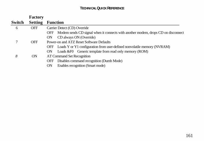
TECHNICAL QUICK REFERENCE
161
FactorySwitch Setting Function
6 OFF Carrier Detect (CD) OverrideOFF Modem sends CD signal when it connects with another modem, drops CD on disconnectON CD always ON (Override)
7 OFF Power-on and ATZ Reset Software DefaultsOFF Loads Y or Y1 configuration from user-defined nonvolatile memory (NVRAM)ON Loads &F0Generic template from read only memory (ROM)
8 ON AT Command Set RecognitionOFF Disables command recognition (Dumb Mode)ON Enables recognition (Smart mode)

TECHNICAL QUICK REFERENCE
162
S-RegistersTo change a setting, use the ATSr=n command, where r is the register and n is a decimalvalue from 0 − 255 (unless otherwise indicated).
Register Default FunctionS0 0 Sets the number of rings on which to answer in Auto Answer Mode. When set to
0, Auto Answer is disabled.
S1 0 Counts and stores the number of rings from an incoming call. (S0 must be greaterthan 0.)
S2 43 Stores the ASCII decimal code for the escape code character. Default character is+. A value of 128 – 255 disables the escape code.
S3 13 Stores the ASCII code for the Carriage Return character. Valid range is 0 –127.
S4 10 Stores the ASCII decimal code for the Line Feed character. Valid range is 0 –127.
S5 8 Stores the ASCII decimal code for the Backspace character. A value of 128−255 disables the Backspace key’s delete function.

TECHNICAL QUICK REFERENCE
163
Register Default FunctionS6 2 Sets the number of seconds the modem waits before dialing. If Xn is set to X2 or
X4, this is the time-out length if there isn't a dial tone.
S7 60 Sets the number of seconds the modem waits for a carrier. May be set for muchlonger duration if, for example, the modem is originating an international connection.
S8 2 Sets the duration, in seconds, for the pause (,) option in the Dial command.
S9 6 Sets the required duration, in tenths of a second, of the remote modem’s carriersignal before recognition by the Sportster modem.
S10 7 Sets the duration, in tenths of a second, that the modem waits to hang up after lossof carrier. This guard time allows the modem to distinguish between a linedisturbance from a true disconnect (hang up) by the remote modem.
While we don’t recommend connecting the modem to a line with call waiting, if youhave it, you may wish to adjust this setting upward to prevent the modem frommisinterpreting the second call signal as a disconnect by the remote modem.

TECHNICAL QUICK REFERENCE
164
Register Default Function S10 (cont.) A better alternative is to ask your phone company how to temporarily disable call
waiting (usually *70W). For example: ATDT *70W phone number.
Note: If you set S10 = 255, the modem will not hang up when carrier is lost.Dropping DTR hangs up the modem.
S11 70 Sets the duration and spacing, in milliseconds, for tone dialing.
S12 50 Sets the duration, in fiftieths of a second, of the guard time for the escape codesequence (+++).
S13 0 Bit-mapped register. Select the bit(s) you want on and set S13 to the total of thevalues in the Value column. For example, ATS13 = 17 enables bit 0 (value is 1) andbit 4 (value is 16).
Bit Value Result0 1 Reset when DTR drops.1 2 Reset non-MNP transmit buffer from 1.5K to 128
bytes.*2 4 Set backspace key to delete.3 8 On DTR signal, auto dial the number stored in
NVRAM at position 0.

TECHNICAL QUICK REFERENCE
165
Register Default Function S13 (cont.) Bit Value Result
4 16 At power on/reset, Auto Dial the number stored inNVRAM at position 0.
5 32 Reserved6 64 Disable quick retrains.7 128 Disconnect on escape code.
* The 1.5K-byte non-ARQ buffer allows data transfer with Xmodem- and Ymodem-type file transfer protocolswithout using flow control.The 128-byte option lets remote users with slower modems keep data you’re sending from scrolling off theirscreens. When remote users send your computer an XOFF (Ctrl-S) and you stop transmitting, the data in transitfrom your modem’s buffer doesn’t exceed the size of their screen.This is also very helpful in situations when a remote modem/printer application is losing characters.
S15 0 Bit-mapped register setup. To set the register, see instructions for S13.
Bit Value Result0 1 Disable ARQ/MNP for V.22.1 2 Disable ARQ/MNP for V.22bis.2 4 Disable ARQ/MNP V.32/V.32bis/V.32terbo.3 8 Disable MNP handshake.4 16 Disable MNP level 4.5 32 Disable MNP level 3.

TECHNICAL QUICK REFERENCE
166
Register Default Function S15 (cont.) Bit Value Result
6 64 MNP incompatibility.7 128 Disable V.42 operation.To disable V.42 detect phase, select the total of the values for bits 3and 7.
S16 0 Bit-mapped register setup. To set the register, see instructions for S13.Bit Value Result0 1 Reserved1 2 Reserved2 4 Touch tone test.4 8 Use internal test pattern.
S18 0 Test timer for &T loopback testing. Sets the time in seconds of testing before themodem automatically times out and terminates the test. When set to 0, the timer isdisabled. Valid range is 1-255.
S19 0 Sets the duration, in minutes, for the inactivity timer. The timer activates when thereis no data activity on the phone line; at time-out the modem hangs up. S19 = 0disables the timer.
S21 10 Sets the length, in 10-millisecond units, of breaks sent from the modem to the computer; applies to MNPor V.42 mode only.

TECHNICAL QUICK REFERENCE
167
Register Default FunctionS22 17 Stores the ASCII decimal code for the XON character.
S23 19 Stores the ASCII decimal code for the XOFF character.
S25 20 Sets the duration, in hundredths of a second, that DTR must be dropped so that themodem doesn’t interpret a random glitch as a DTR loss. (Most users will want touse the default; this register is useful for setting compatibility with older systemsrunning under older operating software.)
S27 0 Bit-mapped register setup. To set the register, see instructions for S13.
Bit Value Result0 1 Enables ITU-T V.21 modulation at 300 bps for overseas calls; in
V.21 mode, the modem answers both overseas and domestic(U.S. and Canada) calls, but only originates V.21 calls. (DefaultBell 103)
1 2 Enables unencoded (non-trellis coded) modulation in V.32 mode.2 4 Disables V.32 modulation.3 8 Disables 2100 Hz answer tone to allow two V.42 modems to
connect faster.4 16 Enables V.23 fallback mode.5 32 Disables V.32bis mode.6 64 Disable V.42 selective reject.

TECHNICAL QUICK REFERENCE
168
Register Default FunctionS27 (cont.) Bit Value Result
7 128 Software compatibility mode. This setting disables thecodes and displays the 9600 code instead. The actualrate of the call can be viewed on the ATI6 screen.Used for unusual software incompatibilities. Somesoftware may not accept 7200, 12,000, and 14,400bps or greater result codes.
S28 0 Eliminates the V.32 answer tones for a faster connection.
8 Default item, all times are in tenths of seconds.
255 Disables all connections except V.32 at 9600 bps.
S29 20 Sets the duration, in tenths of a second, of the V.21 answer mode fallback timer.
S30 - Reserved
S31 - Reserved
S32 2 Bit-mapped register setup. To set the register, see the instructions for S13.
Bit Value Result0 1 V.8 Call Indicate enabled.1 2 Enables V.8 mode.

TECHNICAL QUICK REFERENCE
169
Register Default FunctionS32 (cont.) Bit Value Result
2 4 Reserved.3 8 Disable V.34 modulation.4 16 Disable V.34+ modulation.5-7 32-128 Reserved.
S33 0 Bit-mapped register setup. To set the register, see the instructions for S13.
Bit Value Result0 1 Disable 2400 symbol rate.1 2 Disable 2743 symbol rate.2 4 Disable 2800 symbol rate.3 8 Disable 3000 symbol rate.4 16 Disable 3200 symbol rate.5 32 Disable 3429 symbol rate.6 64 Reserved7 128 Disable shaping.
S34 0 Bit-mapped register setup. To set registers, see instructions for S13.
Bit Value Result0 1 Disable 8S-2D trellis encoding.1 2 Disable 16S-4D trellis encoding.

TECHNICAL QUICK REFERENCE
170
Register Default FunctionS34 (cont.) Bit Value Result
2 4 Disable 32S-2D trellis encoding.3 8 Disable 64S-4D trellis encoding.4 16 Disable non-linear coding.5 32 Disable TX level deviation.6 64 Disable Pre-emphasis.7 128 Disable Pre-coding.
S35 0 Bit-mapped register setup. To set registers, see instructions for S13.Bit Value Result0-2 1-7 Limit back channel rate.
1 = 28800 max.2 = 26400 max.3 = 24000 max.4 = 21600 max.5 = 19200 max.6 = 16800 max.7 = 14400 max.
3 8 Force RBS operation4-7 12-128 Reserved.

TECHNICAL QUICK REFERENCE
171
Register Default FunctionS38 0 Sets an optional delay, in seconds, before a forced hang-up and clearing of the
Transmit buffer when DTR drops during an ARQ call. This allows time for aremote modem to acknowledge receipt of all transmitted data before it isdisconnected. The modem immediately hangs up when DTR drops. This optiononly applies to connections terminated by dropping DTR. If the modem receives theATH command, it ignores S38 and immediately hangs up.
S39-S40 Reserved
S41 0 Bit-mapped register setup. To set registers, see instructions for S13.
Bit Value Result0 1 Distinctive ring enabled.1-7 2-128 Reserved

TECHNICAL QUICK REFERENCE
172
The Serial InterfaceThe serial interface is a standard developed by the Electronic Industries Association(EIA). It defines the signals and voltages used when data is exchanged between acomputer and a modem or serial printer.
The entire standard covers many more functions than are used in most datacommunications applications. Data is transmitted between the devices over a shieldedserial cable with a 25-pin male (DB-25) connector to the modem and a 25-pin, 9-pin, 8-pin, or custom-built connector to the computer.
FCC regulations require the use of a shielded cable when connecting a modem to acomputer to ensure minimal interference with radio and television.
Pin assignments are factory-set in the Sportster modem to match the standard DB-25assignments in the following table. DB-9 connectors for IBM/AT-compatiblecomputers should be wired at the computer end of the cable as shown in the DB-9column.

TECHNICAL QUICK REFERENCE
173
Serial Interface Pin DefinitionsSignal Source
DB-25 DB-9 Circuit Function Computer/Modem
1 — AA Chassis Ground Both2 3 BA Transmitted Data Computer3 2 BB Received Data Modem4 7 CA Request to Send Computer5 8 CB Clear to Send Modem6 6 CC Data Set Ready Modem7 5 AB Signal Ground Both8 1 CF Carrier Detect Modem12 — SCF Speed Indicate Modem20 4 CD Data Terminal Ready Computer22 9 CE Ring Indicate Modem

REGULATORY INFORMATION
174
Manufacturer’s Declarationof Conformity3Com7770 North Frontage RoadSkokie, Illinois 60077-2690U.S.A.
declares that the product U.S. RoboticsSportster 33600 Faxmodem conforms to theFCC’s specifications:
Part 15:Operation is subject to the following twoconditions:(1) this device may not cause harmful
electromagnetic interference, and(2) this device must accept any interference
received including interference that maycause undesired operations.
Part 68:This equipment complies with FCC Rules Part68. Located on the bottom of the modem isthe FCC Registration Number and RingerEquivalence Number (REN). You mustprovide this information to the telephonecompany when requested.
The REN is used to determine the number ofdevices you may legally connect to yourtelephone line. In most areas, the sum of theREN of all devices connected to one line mustnot exceed five (5.0). You should contactyour telephone company to determine themaximum REN for your calling area.
This equipment uses the following USOC jacks:RJ11C.
This equipment may not be used on coin serviceprovided by the telephone company.

REGULATORY INFORMATION
175
Connection to party lines is subject to statetariffs.
An FCC compliant telephone cord andmodular plug are provided with this equipment,which is designed to connect to the telephonenetwork or premises wiring using a Part 68compliant compatible jack. See installationinstructions for details.
Caution to the UserThe user is cautioned that any changes ormodifications not expressly approved by theparty responsible for compliance could voidthe user’s authority to operate the equipment.
IC (Canada)This digital apparatus does not exceed theClass B limits for radio noise emissions fromdigital apparatus set out in the interference-causing equipment standard entitled DigitalApparatus, ICES-003 of Industry Canada.
Cet appareil numérique respecte les limites debruits radioélectriques applicables auxappareils numériques de Classe B préscritesdans la norme sur le matériel brouilleur:Appareils Numériques, NMB-003 édictéepar l'Industrie Canada.
UL Listing/CUL ListingThis information technology equipment is UL-Listed and CUL-Listed for use with UL-Listedpersonal computers that have installationinstructions detailing user installation of cardcage accessories.
Connecting to the Telephone CompanyIt is not necessary to notify the telephonecompany before installing the modem.However, the telephone company mayrequest the telephone number(s) to which theSportster modem is connected and the FCCinformation printed on this page.

REGULATORY INFORMATION
176
Be sure that the telephone line you areconnecting the modem to is a standardanalog line and not a digital (PBX), party, orcoin telephone line.
If the modem is malfunctioning, it may affectthe telephone lines. In this case, disconnectthe modem until the source of the difficulty istraced.
Fax BrandingThe Telephone Consumer Protection Act of1991 makes it unlawful for any person to use acomputer or other electronic device, includingfax machines, to send any message unless suchmessage clearly contains in a margin at the topor bottom of each transmitted page or on thefirst page of the transmission, the date and timeit is sent, an identification of the business orother entity, or other individual sending themessage, and the telephone number of the
sending machine or of such business, otherentity, or individual. (The telephone numberprovided may not be a 900 number or anyother number for which charges exceed localor long-distance transmission charges.)
In order to program this information into yourSportster modem, refer to the RapidCommmanual on the CD-ROM that shipped withyour modem. If you’re using a differentcommunications software program, refer to itsmanual.
Radio and Television InterferenceThis equipment generates and uses radiofrequency energy and if not installed and usedproperly, in strict accordance with themanufacturer’s instructions, may causeinterference to radio and television reception.The modem has been tested and found tocomply with the limits for a Class B computing

REGULATORY INFORMATION
177
device in accordance with the specifications inPart 15 of FCC rules, which are designed toprovide reasonable protection against suchinterference in a residential installation.
However, there is no guarantee thatinterference will not occur in a particularinstallation. If this device does causeinterference to radio or television reception,which you can determine by monitoringreception when the modem is installed andwhen it is removed from the computer, try tocorrect the problem with one or more of thefollowing measures:
• Re-orient the receiving antenna (fortelevisions with antenna reception only) orcable input device.
• Relocate the computer with respect to thereceiver.
• Relocate the computer and/or the receiverso that they are on separate branch circuits.
If necessary, consult your dealer or anexperienced radio/television technician foradditional suggestions. You may find thefollowing booklet, prepared by the FederalCommunications Commission, helpful:
How to Identify and Resolve Radio-TV Interference ProblemsStock No. 004-000-0345-4U.S. Government Printing OfficeWashington, DC 20402
In accordance with Part 15 of the FCC rules,the user is cautioned that any changes ormodifications to the equipment described inthis manual that are not expressly approved by3Com could void the user’s authority tooperate the equipment.

REGULATORY INFORMATION
178
For Canadian Modem UsersNOTICE: The Industry Canada (IC) labelidentifies certified equipment. This certificationmeans the equipment meets certaintelecommunications network protective,operational, and safetyrequirements as prescribed in the appropriateTerminal Equipment Technical Requirementsdocument(s). The Department does notguarantee the equipment will operate to theuser’s satisfaction.
Before installing this equipment, users shouldensure that it is permissible to be connected tothe facilities of the local telecommunicationscompany. The equipment must also beinstalled using an acceptable method ofconnection. In some cases, the company’sinside wiring associated with a single-line,individual service may be extended by means
of a certified connector assembly (telephoneextension cord.) The customer should beaware that compliance with the aboveconditions may not prevent degradation ofservice in some situations. Currently,telecommunication companies do not allowusers to connect their equipment to jacksexcept in precise situations that are spelled outin tariffing arrangements with those companies.
Repairs to certified equipment should becoordinated by a representative designated bythe supplier. Any repairs or alterations madeby the user to this equipment, or equipmentmalfunctions, may give the telecommunicationscompany cause to request the user todisconnect the equipment.
For your own protection, make sure that theelectrical ground connections of the powerutility, telephone lines, and internal metallic

REGULATORY INFORMATION
179
water pipe system, if present, are connectedtogether. This precaution may be particularlyimportant in rural areas.
CAUTION: Do NOT attempt to make suchconnections yourself. Instead, contact anelectric inspection authority or electrician, asappropriate.
NOTICE: The Ringer Equivalence Number(REN) assigned to each terminal deviceprovides an indication of the maximum numberof terminals allowed to be connected to atelephone interface. The termination on aninterface may consist of any combination ofdevices subject only to the requirement that thesum of the Ringer Equivalence Numbers of allthe devices does not exceed 5.
The Ringer Equivalence Number is located onthe bottom of the modem’s case (external
modems) or on the modem’s circuit board(internal modems).WARRANTY AND REPAIR SERVICECENTER:
Keating Technologies25 Royal Crest Court, Suite 200Markham, ONT L3R 9X4
AVIS: L'étiquette de Industrie Canadaidentifie le matériel homologué. Cette étiquettecertifie que le matériel est conforme à certainesnormes de protection, d'exploitation et desécurité des réseaux de télécommunications.Le Ministére n’assure toutefois pas que lematériel fonctionnera à la satisfaction del’utilisateur.
Avant d’installer ce matériel, l’utilisateur doits’assurer qu’il est permis de le raccorder auxinstallations de l’enterprise locale de

REGULATORY INFORMATION
180
télécommunication. Le matériel doit égalementêtre installé en suivant une méthode acceptéede raccordment. L’abonné ne doit pas oublierqu’il est possible que la conformité auxconditions énoncées ci-dessus n’empêche pasle dégradation du service dans certainessituations.
Les réparations de matériel homologué doiventêtre effectuées par un centre d’entretiencanadien autorisé désigné par le fournissuer.La compagnie de télécommunications peutdemander à l’utilasateur de débrancher unappareil à la suite de réparations ou demodifications effectuées par l’utilasateur ou àcause de mauvais fonctionnement.
Pour sa propre protection, l’utilisateur doits’assurer que tous les fils de mise à la terre dela source d’énergie électrique, des lignestéléphoniques et des canalisations d’eau
métalliques, s’il y en a, sont raccordéensemble. Cette précaution estparticulièrement importante dans les régionsrurales.
Avertissment: L’utilisateur ne doit pas tenterde faire ces raccordements lui même; il doitavoir recours à un service d’inspection desinstallations électriques, ou á un électricien,selon le cas.
NOTICE: L’Indice d’Equivalence de laSonnerie (IES) de chaque appareil donne uneindication du nombre maximal de terminaux quipeut être branché à l’interface téléphonique.La termination d’une interface peut consisterde n’importe qu’elle combinaison d’appareilssur le réseau, seulement si la somme des IESde tous les appareils n’excède pas 5.

REGULATORY INFORMATION
181
L'Indice d'Equivalence de la Sonnerie (IES)est situé au revers du modem (modemsexternes), ou sur le circuit imprimé (modemsinternes).
Centre de guarantie et de service après-vente:
Keating Technologies25 Royal Crest Court, Suite 200Markham, ONT L3R 9X4
Limited Warranty
U.S. Robotics Access Corp., a subsidiaryof 3Com Corporation, warrants to theoriginal end-user purchaser that thisproduct will be free from defects inmaterials and workmanship for a period offive years from the date of purchase. Duringthe limited warranty period, and upon proofof purchase, the product will be repaired orreplaced (with the same or a similar model,
which may be a refurbished model) at3Com’s option, without charge for eitherparts or labor. This limited warranty shallnot apply if the product is modified,tampered with, misused, or subjected toabnormal working conditions (including, butnot limited to, lightning and water damage).
THIS LIMITED WARRANTY DOESNOT GUARANTEE YOUUNINTERRUPTED SERVICE. REPAIROR REPLACEMENT AS PROVIDEDUNDER THIS LIMITED WARRANTYIS THE EXCLUSIVE REMEDY OF THEPURCHASER. THIS LIMITEDWARRANTY IS IN LIEU OF ALLOTHER WARRANTIES, EXPRESS ORIMPLIED, INCLUDING, BUT NOTLIMITED TO, ANY IMPLIEDWARRANTY OF

REGULATORY INFORMATION
182
MERCHANTABILITY OR FITNESSFOR A PARTICULAR USE ORPURPOSE. U.S. ROBOTICS SHALL INNO EVENT BE LIABLE FOR ANYSPECIAL, INDIRECT, INCIDENTAL,PUNITIVE, OR CONSEQUENTIALDAMAGES OF ANY KIND ORCHARACTER, INCLUDING,WITHOUT LIMITATION, LOSS OFREVENUE OR PROFITS, FAILURE TOREALIZE SAVINGS OR OTHERBENEFITS, LOSS OF DATA OR USE,DAMAGE TO EQUIPMENT, ANDCLAIMS AGAINST THE PURCHASERBY ANY THIRD PERSON, EVEN IFU.S. ROBOTICS HAS BEEN ADVISEDOF THE POSSIBILITY OF SUCHDAMAGES.This limited warranty gives you specificlegal rights. You may have others, which
vary from state to state. Some states do notallow limitations on duration of an impliedwarranty, or the exclusion or limitation ofincidental or consequential damages, so theabove exclusion or limitation may not applyto you.
To obtain service under this limited warranty,contact the 3Com Technical SupportDepartment at 847-982-5151 or by mail at3Com, 7770 N. Frontage Road, Attn.:Technical Support Dept., Skokie, Illinois60077-2690. You will be given a ServiceRepair Order (“SRO”) number to help 3Comkeep track of your limited warranty request.Once you have received your SRO number,take or send the product, postage prepaid andinsured, to 3Com, Attn: RMA, [your SRO#],6201 W. Oakton, East Dock, Morton Grove,IL 60053. Pack the modem in a strong

REGULATORY INFORMATION
183
corrugated cardboard box with plenty ofpacking material. DO NOT send the modemback in its original box. DO NOT sendanything but the modem (do not send back thepower supply, CD-ROM, documentation,etc.). If possible, send the modem via a couriercapable of tracking the progress of theshipment. Include proof of the date ofpurchase. IMPORTANT: If you send yourunit, pack it securely, and be sure that yourSRO number is visible on the outside of thepackage.

Index
184
AAmerica Online, U.S. Robotics online supportand, 122American Standard Code for Information
Interchange. See ASCIIanalog loopback, 127analog phone lines, vs. digital, 15, 24, 35, 39analog signals, 127answer mode, 127AOL. See America Online, U.S. Roboticsonline support andARQ. See Automatic Repeat reQuestASCII (American Standard Code forInformation Interchange), 127asynchronous transmission, 127AT commands, 140-152auto answer, 128auto answer (AA) light, 138auto dial, 138
Automatic Repeat reQuest (ARQ) light, 138
Bbaud rate, 130BBS, U.S. Robotics, 119-120binary digit, 128bit rate, 128bits per second (bps), 128buffer, 128byte, 128
Ccarrier, 129carrier detect (CD) light, 138character, 129characters per second (cps), 129
low, errors and, 117

Index
185
class 1 and 2.0 faxing standards, 129clear to send (CS) light, 138COM ports
conflicts, 113-114and Plug and play installations, 4, 19-20
command summary, 140-152communications software
and flow control, 116-117installing other fax/data software, 75-76installing RapidComm software, 57-74UART, 76
CompuServe, U.S. Robotics online supportand, 122
Connections CD-ROMModem Station, 77-100Modem Update Wizard, 101-112software installation, 57-74
CRC. See Cyclic Redundancy Checking
Cyclic Redundancy Checking (CRC), 117-118, 129
Ddata compression table, 129data mode, 130data terminal (terminating) equipment (DTE),130data terminal ready (TR) light, 138default settings, 130detect phase, 130dictionary, 130digital loopback, 130digital signals, 130DIP switches, 153-154drivers, modem
installing, 25-32, 40-47, 49-56DTE. See data terminal (terminating) equipment

Index
186
duplex, 130
EEIA. See Electronic Industries AssociationElectronic Industries Association (EIA), 131error control, 131
disabling, 116error control/ (ARQ/) light, 138external modems
and faxing, 72-74hardware installation
Windows 3.x, 33-36Windows 95, 37-48
and serial cable, 33-34, 37-38
Ffacsimile (fax), 131fax mode, 131
fax operations (FAX) light, 138faxing with RapidComm software, 72-74flow control, 75-76, 116-117, 131frame, 131front panel lights, summary, 138FTP, U.S. Robotics online support and, 122full duplex, 131
Gglossary, 127-136
Hhalf duplex, 131hertz (Hz), 132

Index
187
Iinternal modems
faxing with, 72-74hardware installation
Windows 3.x, 3-18Windows 95, 19-32
and Plug and Play installation, 4, 19-20International Telegraph and TelephoneConsultative Committee (ITU-T), 132IRQs, 3-12
conflicts, 113-114ISA expansion slots, 14, 22ITU-T. See International Telegraph and
Telephone Consultative Committee
Jjumper pins, 4, 11-12, 20jumper shunts, 4, 11-12, 20
LLAPM. See Link Access Procedure forModemsLink Access Procedure for Modems (LAPM),132local echo, 132
turning off, 114
MMicrocom Networking Protocol (MNP), 132MNP. See Microcom Networking ProtocolModem Station, 77-99
installing, 77-79using, 80-99
Modem Update Wizard, 101-112installing, 101-105using, 106-112

Index
188
Nnonvolatile memory (NVRAM), 132NVRAM. See nonvolatile memory
Ooff/on hook, 132online fallback/fall forward, 133online help resources, 119-126originate mode, 133
Pparity, 116, 119, 133Plug and Play installation, 4, 19-20protocol, 133
RRAM (random access memory), 133random access memory. See RAMRapidComm software
faxing with, 72-74installing, 57-74troubleshooting, 124-125
read only memory (ROM), 134received data (RD) light, 138remote digital loopback, 133remote echo, 133
Ss-registers, 155-164send data (SD) light, 138serial cable, purchasing, 33-34, 37-38serial interface, 165-166
pin definitions, 166

Index
189
serial number, modem, 15, 23serial (COM) ports, 3-12, 19-20, 34, 38
conflicts, 113-114serial transmission, 134shunts, jumper, 4, 10-12, 20start/stop bits, 116, 119, 134
TTechnical Reference Guide, downloading, 120-121terminal mode, 114-119, 134Terminate and Stay Resident programs, errorsand, 117-118throughput, 134troubleshooting, 113-125
RapidComm software, 124-125TSR. See Terminate and Stay Residentprograms
UUART, 76upgrading/updating modems, 101-112U.S. Robotics
BBS, 119-120online help resources, 119-126Technical Reference Guide,downloading, 120-121Technical Support Hotline, 123
VV.17 fax transmissions, errors and, 118

Index
190
WWindows 95
determining your version, 2World Wide Web (WWW), U.S. Roboticsonline support and, 122
Xx2 technology, 2, 101-112Xmodem, 136xon/xoff, 136
YYmodem, 136Ymodem G, 136
ZZmodem, 136